a fast dense stereo matching algorithm with an application to 3d
TRANSCRIPT
A Fast Dense Stereo Matching Algorithm with an Application to 3DOccupancy Mapping using Quadrocopters
Radouane Ait-Jellal and Andreas Zell
Abstract— In this paper, we propose a fast algorithm forcomputing stereo correspondences and correcting the mis-matches. The correspondences are computed using stereo blockmatching and refined with a depth-aware method. We compute16 disparities at the same time using SSE instructions. Weevaluated our method on the Middlebury benchmark andobtained promosing results for practical realtime applications.The use of SSE instructions allows us to reduce the timeneeded to process the Tsukuba stereo pair to 8 milliseconds(125 fps) on a Core i5 CPU with 2x3.3 GHz. Our disparityrefinement method has corrected 40% of the wrong matcheswith an additional computational time of 5.2% (0.41ms). Thealgorithm has been used to build 3D occupancy grid maps fromstereo images. We used the datasets provided by the EuRoCRobotic Challenge. The reconstruction was accurate enough toperform realtime safe navigation.
I. INTRODUCTIONIn binocular stereo, we are given two images captured
by a pair of stereo cameras, left camera and right camera,such that one right camera is shifted (along the x-axis)with respect to the other camera with given distance Bcalled baseline. The task is to find for each point of thereference image its corresponding pixel on the target image.In the standard stereo correspondence form, the search forcorrespondence of a pixel p(x, y) on the reference image isrestricted to a 1D search along the horizontal line havingthe same y-coordinate on the target image. A commonlymade assumption in stereo is to consider the intensity beingconsistent. In other words, it is assumed that the intensity ofa pixel on the reference image is equal to the intensity ofits corresponding pixel on the target image. Despite being aclassical problem of early vision, stereo matching is a diffi-cult problem because of half-occlusions, textureless regions,repetitive patterns, sensor noise and depth discontinuities.Half-occlusions occur when a point is seen only by onecamera. Asking to determine the correspondence for half-occluded points is an ill-structured problem. The best thingto do in this case is to clearly identity them. On texturelessregions, constraints made upon intensity consistency are notdiscriminative. There is a need to carefully use informationfrom other parts of the image to enhance the results onthese textureless regions. The existence of repetitive pat-terns could introduce ambiguities. Developing algorithmsthat try to handle all of the afore-mentioned challengesdoes lead to impractically slow algorithms. For applicationslike environment mapping using stereo cameras mounted on
R. Ait-Jellal is with the Chair of Cognitive Systems, headed byProf. A. Zell, Computer Science Department, University of Tubingen,Sand 1, D-72076 Tubingen, Germany {radouane.ait-jellal,[email protected]}
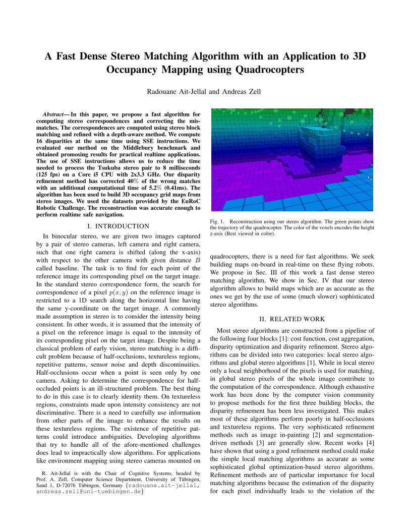
Fig. 1. Reconstruction using our stereo algorithm. The green points showthe trajectory of the quadrocopter. The color of the voxels encodes the heightz-axis (Best viewed in color).
quadrocopters, there is a need for fast algorithms. We seekbuilding maps on-board in real-time on these flying robots.We propose in Sec. III of this work a fast dense stereomatching algorithm. We show in Sec. IV that our stereoalgorithm allows to build maps which are as accurate as theones we get by the use of some (much slower) sophisticatedstereo algorithms.
II. RELATED WORK
Most stereo algorithms are constructed from a pipeline ofthe following four blocks [1]: cost function, cost aggregation,disparity optimization and disparity refinement. Stereo algo-rithms can be divided into two categories: local stereo algo-rithms and global stereo algorithms [1]. While in local stereoonly a local neighborhood of the pixels is used for matching,in global stereo pixels of the whole image contribute tothe computation of the correspondence. Although exhaustivework has been done by the computer vision communityto propose methods for the first three building blocks, thedisparity refinement has been less investigated. This makesmost of these algorithms perform poorly in half-occlusionsand textureless regions. The very sophisticated refinementmethods such as image in-painting [2] and segmentation-driven methods [3] are generally slow. Recent works [4]have shown that using a good refinement method could makethe simple local matching algorithms as accurate as somesophisticated global optimization-based stereo algorithms.Refinement methods are of particular importance for localmatching algorithms because the estimation of the disparityfor each pixel individually leads to the violation of the

smoothness constraint of the objects.The global optimization based stereo algorithms [5] [6]
[7] model the correspondence problem as a Markov randomfield (MRF) problem. They design an energy function torepresent the global cost associated with the selection of adisparity for all of the pixels in the image. The proposedmethods differ in the way the energy function is designed.Nevertheless, the energy function for all these algorithmscontains a data term and a smoothness term. The data termmeasures how the selected disparity fits the data. This isdone by warping the reference image using as displacementvector map, the candidate disparity map. In the ideal casethis will exactly generate an image similar to the targetimage. In practice we optimize the error between them.The smoothness term insures the coherence of the disparitymap. The classical least-squares methods for solving suchenergy minimization problems are impractical due to the datadimension. Approximating the minimal energy by the useof graph cuts [7] makes global stereo algorithms efficientenough and suitable for some off-line applications.
Local stereo algorithms [4] [8] [9] as opposed to globalstereo can be implemented very efficiently. Moreover, theyare suitable for parallel computing either using softwareinstructions such as SSE or by using special hardware suchas GPUs and FPGAs. It is not always true that local stereomatching algorithms are faster than global matching algo-rithms. Trying to improve the accuracy of correlation basedlocal stereo, the researchers have proposed different types ofcost functions [10] and aggregation methods [11]. The basicblock matching algorithm assumes the disparities to be thesame within the correlation window [9]. This assumption isviolated at the depth discontinuities. Correlation windows ofsmaller sizes could reduce the errors. Unfortunately, makingthe window sizes smaller can also significantly decrease thesignal to noise ratio. This yields unstable disparity values.[12] proposed the variables correlation windows in which thedisparity is not computed for the pixel at the center of thewindows as usual but in predefined positions. The disparityassociated to the windows in which the lowest cost is found isthen selected.[13] combined correlation windows of differentsizes. Adapting the size and the shape of the correlationwindows individually [8] [9] for each pixel is the way toget the best results, but this could slow down the algorithmextremely [9]. The shape of the correlation windows canbe adapted by weighting the contribution of the differentpixels to the final aggregated cost. The more the disparityof a neighboring pixel is similar to the disparity of centralpixel, the larger the weight should be. Color similarity is acommon way for estimating the weights [8]. With regard tothe design of cost functions, several methods [10] have beenproposed by the computer vision community. These methodsinclude the sum of absolute differences SAD, the sum ofsquared differences SSD and the normalized cross correlationNCC. Variants of these methods exist like zero-mean sum ofabsolute differences ZSAD. Compared to NCC and SSD,SAD does require only simple +/- arithmetic operations. Asa result it can be computed very efficiently. In our algorithm
we have chosen SAD not only because it is efficient but alsobecause it is more robust against noise than the SSD.
There is a third category of stereo algorithms lying be-tween global stereo and local stereo. These hybrid stereoalgorithms are known as semi-global matching algorithmsSGM. Hirschmller [14] was the first to propose this kind ofalgorithms. [15] has proposed a variant of SGM. Semi-globalmatching algorithms are fast but, they are still considerablyslower than the efficient block matching algorithms.
III. THE STEREO ALGORITHM
A. Initial disparities computation
We compute the correspondences using the sum of ab-solute differences (SAD) cost function. We aggregate theSAD over a local window of fixed size. In order to keepthe algorithm faster we have chosen neither to use multiplecorrelation windows nor to adapt the window shape and size.To make the system robust against noise we compute theSAD not on the intensities directly but on their derivativesalong the x-axis. We use the Sobel operator to compute thesederivatives. This way, we build a disparity space image DSI[16]. The DSI stores for each pixel of the reference imagethe similarity costs on the target image for the differentdisparities. The input pixels are coded as 8 bit charactersand the computation of the costs for the different disparitiescan be done independently. This allows us to process 16disparities at the same time using Streaming SIMD Exten-sions (SSE). The processors supporting SSE are providedwith internal registers of 128 bits size. We load the registerswith 16 pixels (128 bits) to be processed. Then we unpackthe 128 bits register into two 128 bits registers such thateach pixel is coded with 16 bits and the 8 high-order bits setto zero. We then send a signal to the processor arithmeticunit to perform the computation. Having the pixels codedin 16 bits is required in order not to overrun the buffersize. The accumulated sums of the absulte differences arestored in 128 bits variables. The use of SSE instructionsmakes the computation of the cost aggregation task veryefficient. Cost aggregation is the most time consuming task ofalmost any correlation based local algorithm. Thus, makingit efficient makes the overall algorithm fast. One of thetraditional techniques to speed up the computation for blockmatching stereo is to use integral images. This makes thecomputation of the cost independent of the window sizeand very usefull when we have to deal with large windows.However, a relatively small window of size 5x5 has best fitour needs and we estimate that we do not need to use theintegral images. The aggregated cost at the pixel p(x, y) isgiven by Eq. 1.
Costsad(d) =∑i,j∈W
|OI1(x+ i, y + j)− OI2(x+ i− d, y + j)| (1)
Where W is the correlation window, OI1(x+ i, y + j) isthe gradient at the position (x+ i, y+ j) on the first image.We perform the simple winner-takes-all strategy to select the

most likely disparity d. The selected disparity d∗ is given bythe Eq. 2.
d∗ = argmdin(Costsad(d)) (2)
B. Mismatches detection and correction
We compute two disparity maps, one with the left imageas reference image and the second disparity map with theright image as reference image. We then proceed witha left-right consistency check for removing the suspectedmismatches. We compare the disparity of a pixel in onedisparity map with its re-projection in the other disparitymap. If the difference is larger than a given threshold thenthe pixel is set to be an outlier. This occurs particularly inregions where the pixel is occluded in the second view andin textureless areas. The result is a disparity map, whichgenerally contains a substantial amount of missing disparities(holes). We illustrate the case of half-occlusions in Fig. 2.The scene is composed of three boxes. The orange box lieson the front and occludes some parts of the green box forthe left-side camera. These occluded parts are shown in greenon the line. The orange box does also occlude some partsof the blue box for the right-side camera. These parts areshown in blue on the line. We use a simple and efficientmethod for filling the holes. It is obvious that the requiredaction is to fill the holes with the background disparities. Thebackground disparities correspond to the small disparities. Inour method we scan the horizontal lines of the disparity mapindependently, and for each line we first identify the holes.Then we compute for each hole the averaged disparity ona local neighborhood on valid pixels on the left and on theright of the hole. We compare these averaged disparities anddecide accordingly which disparities to use to fill the hole.We fit a line on the hole border with smallest disparity andwe compute the missing values by extrapolation. The linefitting process is illustrated in the Fig. 2.
The mismatches correction method described above doesnot require any time consuming preprocessing such assegmentation and plane fitting as proposed by [7]. Ourmethod differs from method [17] used for Depth-ImageBased Rendering (DIBR) and 3D Television in the way thatwe fit horizontal lines to extrapolate the missing values andthey used a constant disparity value for the missing pixels.This method has been abandoned by the DIBR communitybecause it can have visual artifacts for which the humaneye is very sensitive. They preferably opt for more advancedand accordingly complex and time consuming refinementmethods such as image in-painting. We believe that formobile robots the use of our fast hole filling is reasonablygood. Our method differs from the common method basedon interpolation in the sense that interpolation methods blurthe edges at the depth discontinuities. Despite being simple,intuitive and very efficient it has strongly improved theoverall accuracy on the Middlebury benchmark. However,we should notice that this hole filling method can fail whenthere are wide regions of invalid disparities. In that case,the propagated valid disparities might differ from the correct
Fig. 2. Occlusion happens at depth discontinuities. The orange box isin the front and occludes some parts of the other boxes. For filling theinvalid disparities we perform line fitting process based on valid neighboringdisparities and propagate the disparities to the occluded regions.
values. This is why we fill the hole only when the width ofthe gap is smaller than a threshold. In our experiments weset this threshold to be equal to 1/8 of the image width.
C. Edge preserving filter
Generally, objects of the scene are smooth over givenareas and can have depth discontinuities near edges. Thedisparities that we get from the previous steps might containsome unrealistic disparity changes within smooth parts ofthe object. A common post-processing method to enhance thedisparity map is to filter the noise with a smoothing filter. Wefilter the disparity map with the symmetric nearest neighborSSN non-linear filter, which makes the disparity map smoothwhile it does not blur the disparity map at the discontinuities.We found that SSN performs better than the median filter.
IV. 3D RECONSTRUCTION
Building a volumetric occupancy map of the environmentis a very important task for mobile robotics. It allows therobot to be aware of its environment and helps the robotto perform a wide range of tasks, such as safe navigationby avoiding obstacles and exploration. Laser range findersare the commonly used sensors for map building becausethey are very accurate. Unfortunately, the use of laser rangefinders has many drawbacks. Most laser scanners are tooheavy to be carried by Micro-Ariel Vehicles (MAV). Theyare active sensors with a dedicated light source, requiringadditional power for lighting the scene. And due to themechanical scanning system used for moving the beam theyproduce scans at lower frame rates than cameras. Stateof the art laser scanners that attempt to reduce some ofthese drawbacks are quite expensive. Alternative sensorswhich do not have the afore-mentioned drawbacks are stereocameras and RGBD cameras. The Kinect-style RGBD cam-eras provide good range estimates in indoor environments,but they fail when the amount of infrared light is largeand thus are not suitable in sunlight. Stereo cameras arebecoming the sensor of choice to fulfill the afore-mentioned

requirements. Nevertheless, most sophisticated stereo algo-rithms are computationally expensive. This has made thesimple block matching algorithms like the one we proposedwidely used algorithms in real applications. Even the Kinectsensor computes the depth estimation using a block matchingalgorithm implemented on FPGA. The rise of small singleboard computers like the Intel NUC with SSE support andlow power consumption (15 Watt) makes the use of stereoalgorithm for computing the depth on-board flying robots areasonably good choice. In the following we describe howwe build a 3D map using our stereo algorithm. We have usedour stereo algorithm to build volumetric occupancy grid mapsfrom stereo pairs captured by a stereo system mounted ona quadrocopter. We assume that the 6DoF camera poses areknown. We use the Robust Octomap which is an improvedversion of the original Octomap [18]. The Robust Octomap[19] has been designed to specially fit with stereo. TheOctomap based map building system models the environmentby dividing the volume into voxels organizing these voxelsin an Octree structure. The map is updated by integrating thedepth measurements (point clouds) in a probabilistic manner.We have intentionally chosen the application of buildinga map using Octomap because in such applications it istolerated to use less accurate depth measurements as longas the end point is detected within the correct voxel. Thisdoes not apply for the end points which are located near thevoxels boundaries. In this case, slight depth errors could leadto errors in the map.
Unlike many stereo algorithms that do not fill the invalidpixels, our algorithm produces dense environment maps byintegrating fewer measurements. Those algorithms need toview the scene from other poses in order to get validdisparities for the missing points. To insert measurementsfrom our stereo camera we need to generate point cloudsfrom the disparity maps computed by the stereo algorithm.Since the ambiguity of stereo estimates grows quadraticallywith respect to the depth, in [19] they proposed a map updatemethod which deals with this problem. We refer to [19] formore details. In order to compute the disparity map from thestereo images we first need to rectify the stereo images. Theintrinsic cameras parameters including the cameras matricesand the lens distortion coefficients were estimated using theKalibr [20] calibration method. Kalibr uses special patternsfor calibration. These patterns allow for a more preciseestimation of the corner positions and this way provide amore accurate estimation of the cameras parameters whencompared to other methods [21]. Based on these parameterswe compute the rectification transforms using the OpenCVimplementation of the method [22]. To rectify the stereo pairswe remap the input images with the computed rectificationtransforms. The rectification step transforms the real stereosystem to a virtual system in which the cameras are perfectlyaligned and have the same focal length. Note that we needto compute the rectification maps only once and reuse themto rectify all the other stereo pairs. The steps for building anoccupancy map are as follows:
• Rectify the stereo images to restrict the search for thecorrespondences from 2D to 1D.
• Perform dense stereo matching using our algorithmdescribed in Sec. III for computing the disparity map.
• Generate point clouds by re-projecting the points of thereference image to 3D.
• Insert the point clouds (with known 6DoF poses) intothe global map by probabilistically updating the voxelslying between each 3D point of the point cloud and thecamera center.
The reconstruction is evaluated by computing the correla-tion error of our results with respect to the ground truth. TheMatthews correlation coefficient MCC is used a measure forthis purpose.
V. RESULTS
We performed two sets of experiments. First, we testedour dense stereo algorithm using the Middlebury benchmark.Second, we evaluated the reconstruction results using thestereo datasets and the online evaluation tool provided bythe EuRoC Challenge (http://www.euroc-project.eu/).
A. Evaluation of the dense stereo algorithm
We used a window size of 5×5 and set the error thresholdto 0.5 on the benchmark table. The average percent of badpixels on the four stereo pairs (Tsukuba, Venus, Teddy andCones) is 19.7%. Our algorithm is ranked better than theglobal optimization based algorithms graph cut [23] andConstant time belief propagation [6]. We get these goodresults compared to GC and CSBP particularly because theCones stereo pair includes a substantial amount of occludedpixels. This stereo pair includes large occlusions (See Fig.3) which were recovered successfully by our refinementmethod. Like the other algorithms we got the worst resultson the Teddy stereo pair.
We have made our experiments on an Intel Core i5 2×3.3GHz computer with 4GB RAM. We used a correlationwindow of size 5×5 pixels and a post-processing filter ofsize 5x5. The run-times of the different steps are shown inTable II. As one can expect when block matching is used, therun-time grows linearly with respect to the input image sizesand disparity ranges. Although our hole filling method doesrequire only about 5% of matching time, it has corrected40% of the missing disparity values. Reducing this way theaverage of the bad pixels from 32.70% to 19.70%. The finalstep of our algorithm is the filtering of the disparity mapusing an edge preserving filter. To achieve this task we useda median filter with a window size of 5x5. Fig. 4 showsthe percentage of bad pixels before and after the refinement.We used a median filter instead of our the symmetric nearestneighbor (SSN) filter because our implementation of the SSNwas not optimized and made the overall stereo algorithmslower. However, we found that
Although our algorithm is less accurate than the globaloptimization based algorithm TSGO and GC+Occ, our al-gorithm is much faster. While these iterative algorithmsperform the matching in several hundreds of milliseconds our

TABLE IPERFORMANCE EVALUATION ON THE MIDDLEBURY DATASET
Algorithm Avg rank Percentage of bad pixels on all image regionsTsukuba Venus Teddy Cones Average all images
TSGO [5] 33.4 10.0 7.8 16.4 10.2 11.2AdaptingBP [24] 46.3 9.3 5.1 16.7 13.2 13.6
GC+Occ [25] 94.2 7.1 11.3 30.1 19.2 17.4Our method 102.4 16.5 6.5 25.8 19.7 19.7
GC [23] 112.5 9.8 15.0 38.5 25.5 21.6CSBP [6] 122.9 23.8 9.2 27.8 24.7 21.9
RINCensus [26] 123.8 29.5 8.5 24.5 22.5 20.0
Fig. 3. Cones dataset and its occlusion map.
Tsukuba Venus Teddy Cones0
5
10
15
20
25
30
35
40
45
Perc
enta
ge o
f bad p
ixels
With refinement
Without refinement
Fig. 4. Percentage of bad pixels before the refinement (grey) and after therefinement (green).
TABLE IIRUNNING TIME IN MILLISECONDS
Dataset Match &Consistcheck
Hole filling Filtering Max disp Total time
Tsukuba 5.80 0.41 1.31 16 7.52Venus 10.19 0.64 2.41 32 13.24Teddy 15.50 0.76 1.86 64 18.12Cones 14.98 1.27 2.12 64 18.37
Fig. 5. Our results on the Middlebury benchmark. The left column showsthe disparity maps before filling the holes. The second column showsthe results after filling the missing disparities. The last column shows thedisparity maps after filtering with the median filter.
algorithm performs the matching in less than 20 millisecondsfor any stereo pair of the Benchmark. The Fig. 6 shows thecomparison of the running times between our algorithm andthe global stereo algorithms GC and CSBP and the Semi-global stereo algorithm ELAS [15]. The running times forour algorithm, ELAS and CSBP were reported for an IntelCore i5 with 2×3.3 GHz CPU. An OpenCL implementationof the CSBP was used. The running time for GC is reportedfor an Intel Pentium 4 with 2 GHz. Please notice that they-axis has a logarithmic scale.

Our algorithm ELAS+LR CSBP GC+Occ10
0
101
102
103
Runnin
g tim
e in m
sTsukuba
Venus
Teddy
Cones
Fig. 6. Running time comparison. The y-axis has a logarithmic scale.
Fig. 7. Snapshots of the scene to be reconstructed
B. Evaluation of the 3D reconstruction
We used the stereo datasets provided by the EuRoCchallenge. These stereo datasets are captured using a quadro-copter. EuRoC provides three stereo datasets of the samescene with an increasing degree of difficulty. EuRoC pro-vides the true 6DoF poses for all the stereo pairs. We usedthe robot operating system (ROS) to make this experiment.The accuracy of the reconstruction is evaluated using theMatthews correlation coefficient MCC. We speed-up thereconstruction by integrating new measurements only if thedifference between the current pose and the previous poseshas reached a given threshold. As expected, we got the bestaccuracy (MCC=0.81) for the dataset 1. We have done thereconstruction using the ELAS SGM algorithm [15] andobtained maps which are comparable to the ones that we haveobtained with our algorithm. We believe that this is due tothe fact that our algorithm is accurate enough to find in mostcases the voxel which contains the end point of the ray. Fig.7 shows some pictures of the scene to be reconstructed. Wevisualize the reconstructed Octomap using ROS-Rviz. Fig.8 shows some screen-shots of the final map reconstructedusing our stereo algorithm. The color encodes the height (z-axis). The violet color corresponds to lowest altitude and thered color corresponds to highest altitude.
(a)
(b)
Fig. 8. Reconstruction using our stereo algorithm. The green points on (b)show the trajectory of the quadrocopter.
VI. CONCLUSION
We proposed a fast stereo algorithm which fits nicely forthe task of mapping using quadrocopters. The key advantageof our algorithm is its efficiency. It is suitable to use it whenreal-time stereo processing is required on a medium levelembeded PC on a MAV.
REFERENCES
[1] D. Scharstein and R. Szeliski, “A taxonomy and evaluation of densetwo-frame stereo correspondence algorithms,” IJCV, vol. 47, no. 1-3,pp. 7–42, 2002.
[2] L. Wang, J. Jin, R. Yang, and M. Gong, “Stereoscopic inpainting: Jointcolor and depth completion from stereo image,” CVPR, 2008.
[3] D. Lima1, V. Giovani, A. Victorino1, and J. Ferreira, “A disparitymap refinement to enhance weakly-textured urban environment data,”ICAR, 2013.
[4] Z. Ma, K. He, Y. Wei, J. Sun, and E. Wu, “Constant time weightedmedian filtering for stereo matching and beyond,” ICCV, 2013.
[5] M. Mozerov and J. van Weijer, “Accurate stereo matching by two stepglobal optimization,” TIP, 2014.
[6] Q. Yang, W. L., and N. Ahuja, “A constant-space belief propagationalgorithm for stereo matching,” CVPR, 2010.
[7] M. Bleyer and M. Gelautz, “A layered stereo algorithm using imagesegmentation and global visibility constraints,” Asian Conf. on Com-put. Vis ACCV, pp. 25–38, 2011.
[8] K.-J. Yoon and I.-S. Kweon, “Adaptive support-weight approach forcorrespondence search,” IEEE TPAMI, vol. 28, no. 4, pp. 650–656,2006.
[9] T. Kanade and M. Okutomi, “A stereo matching algorithm with anadaptive window: Theory and experiment,” TPAMI, vol. 16, no. 9, pp.920–932, 1994.
[10] H. Hirschmueller and D. Scharstein, “Evaluation of stereo matchingcosts on images with radiometric differences,” IEEE TPAMI, vol. 31,no. 9, pp. 1582–1599, 2009.
[11] M. Dongbo, L. Jiangbo, and N.-D. Minh, “A revisit to cost aggre-gation in stereo matching: How far can we reduce its computationalredundancy,” ICCV, 2011.
[12] O. Veksler, “Fast variable window for stereo correspondence usingintegral images,” CVPR, pp. 556–561, 2003.
[13] S. Adhyapak, N. Kehtarnavaz, and M. Nadin, “Stereo matching viaselective multiple windows,” Journal of Electronic Imaging, vol. 16,no. 1, 2007.
[14] H. Hirschmueller, “Stereo processing by semi-global matching andmutual information,” IEEE TPAMI, vol. 30, no. 2, pp. 328–341, 2008.
[15] A. Geiger, M. Roser, and R. Urtasun, “Efficient large-scale stereomatching,” Asian Conf. on Comput. Vis ACCV, pp. 25–38, 2010.
[16] S.-S. Intille and A.-F. Bobick, “Disparity-space images and largeocclusion stereo,” ICCV, 2013.
[17] P. Lai-Man, Z. Shihang, X. Xuyuan, and Z. Yuesheng, “A new multi-directional extrapolation hole-filling method for dibr,” ICIP, 2011.
[18] K. Wurm, A. Hornung, M. Bennewitz, C. Stachniss, and B. W., “Oc-tomap: A probabilistic, flexible, and compact 3d map representationfor robotic systems,” ICRA, 2010.
[19] K. Schauwecker and A. Zell, “Robust and efficient volumetric oc-cupancy mapping with an application to stereo vision,” ICRA, pp.6102–6107, 2014.
[20] P. Furgale, J. Rehder, and R. Siegwart, “Unified temporal and spatialcalibration for multi-sensor systems,” In Proceedings of the IEEE/RSJInternational Conference on Intelligent Robots and Systems IROS,2013.
[21] Z. Zhang, “A flexible new technique for camera calibration,” IEEETPAMI, vol. 22, no. 11, pp. 1330–1334, 2000.
[22] R. Hartley, “Theory and practice of projective rectification,” IJCV,vol. 25, no. 2, pp. 115–127, 1999.
[23] R. Boykov, Veksler, and Zabih, “Graph cuts using alpha-beta swaps,”PAMI, 2001.
[24] A. Klaus, M. Sormann, and K. K., “Segment-based stereo matchingusing belief propagation and a self-adapting dissimilarity measure,”ICPR, pp. 15–18, 2006.
[25] V. Kolmogorov and R. Boykov, “Computing visual correspondencewith occlusions using graph cuts,” ICCV, 2001.
[26] M. Ma, “Modified census transform based on the related informationof neighborhood for stereo matching algorithm,” Computer Engineer-ing and Applications, 2014.