a drone-based communication system for strategic …
TRANSCRIPT
A DRONE-BASED COMMUNICATION SYSTEM
FOR STRATEGIC AND PUBLIC PROTECTION AND
DISASTER RELIEF (PPDR) APPLICATIONS
A Project Report
submitted by
NEERAJ SHARMA
in partial fulfilment of the requirements
for the award of the degree of
MASTER OF TECHNOLOGY
DEPARTMENT OF ELECTRICAL ENGINEERINGINDIAN INSTITUTE OF TECHNOLOGY MADRAS.
08 MAY 2019


THESIS CERTIFICATE
This is to certify that the thesis titled A Drone-Based Communication System For
Strategic And Public Protection And Disaster Relief (PPDR) Applications, sub-
mitted by NEERAJ SHARMA, to the Indian Institute of Technology, Madras, for the
award of the degree of MTech, is a bona fide record of the research work done by him
under our supervision. The contents of this thesis, in full or in parts, have not been
submitted to any other Institute or University for the award of any degree or diploma.
Prof. 1Research GuideProfessor R. David KoilpillaiDept of Electrical EngineeringIIT-Madras, 600 036
Date: 05 May 2019 Place: Chennai


ACKNOWLEDGEMENTS
I would like to take this opportunity to express my gratitude to our research guide Prof
R. David Koilpillai for constant and continued support all through the project. His
encouragement and guidance helped me put the subject in a presentable shape. I also
thank Dr Devendra Jalihal , Head of Dept of Electrical Engineering , IIT Madras for
his valuable advice for the betterment of the project.This helped me to setup a working
prototype of this emergency communication system and carry out its field test deploy-
ment. I would like to also express my acknowledgement to Dr Suresh Christopher
(ex Chairman, DRDO currently faculty at IITM) for his invaluable insights and DRDO
team at R & D Establishment,Pune for the support of tethered drones in this project. I
would also like to extend our gratitude to the start-up team UBIFLY Technology aka
E-Plane company being run by Suhridh Sundaram, Ashutosh Kumar, Pranjal Mehta and
Siddharth Ramesh for providing with drone-lift to execute my project. Last but not the
least my labmates for their handy support during the field trails.
i

ABSTRACT
KEYWORDS: PPDR, Dead Zone, Spectrum Sensing.
Being in the Corps of Signals for almost a decade, which is the telecommunication
arm of the Indian Army, and having served in varied operational terrains in different
parts of the country, I have experienced many challenges in providing communication
to the deployed units. Few of these challenges relate to providing communication in
areas with little or no network infrastructure, thickly wooded terrain, etc.
This project work focuses on addressing these voids. I have tried to propose a solu-
tion to provide effective communication in the respective scenarios. In doing so, I have
incorporated Drones (Unmanned Aerial Vehicle) to create an ad-hoc communication
support system which can be quickly deployed in inaccessible areas, these areas can be
ones which are, although, near well-established communication infrastructure but due
to dead zone deployment (wherein the transmitter/receiver are so placed that they lack
either forward or backward connectivity or in many cases both of them) lacks adequate
connectivity from it or ones that lack communication infrastructure altogether.
In the first scenario, we have an area of operation in dead ground where communi-
cation is to be provided using the existing communication infrastructure from a nearby
area. In the second scenario, communication is to be provided in a remote, isolated
area where no communication exists in near vicinity.
This proposed setup has applications outside the military strategic domain wherein,
during many unforeseen emergency situations (viz natural calamities, train accidents
forest fires or any large scale congregation), there is a sharp and sudden rise in cellular
communication traffic due to ensuing commotion and influx of people. The existing in-
frastructure is either unable to take on this huge increase in load and gets choked up or
has been damaged and therefore unable to provide service.In such a situation, it can be
suitably adapted to be used by disaster response forces to operate for their coordination
of Personnel Protection and Disaster Relief (PPDR) tasks to bring situation under
control and prevent any further loss of life or material.
iii
Any credits, I happily share with you, but I take full responsibility for any flaws that
might have crept in. We would sincerely welcome the comments and suggestions of
everyone in light of which I may further this work into a full-fledged system.
Key Note
This project is a joint effort of two students namely EE17M002 Pranav Kumar Opal
and EE17M003 Neeraj Sharma and covers two different scenarios for its application.
However this report covers the part of project dealing with GSM for communication
(for second scenario) . The WiFi cloud portion(for first scenario) of the over all project
is covered in the report submitted by EE17M002 Pranav Kumar Opal.
iv
TABLE OF CONTENTS
ACKNOWLEDGEMENTS i
ABSTRACT iii
LIST OF TABLES ix
LIST OF FIGURES xi
ABBREVIATIONS xiii
1 INTRODUCTION 1
1.1 General . . . . . . . . . . . . . . . . . . . . . . . . . . . . . . . . 1
1.2 Problem Statement . . . . . . . . . . . . . . . . . . . . . . . . . . 1
1.2.1 Main features of the proposed PPDR system . . . . . . . . 2
1.2.2 Additional Scenarios To Employ The Same Setup with CertainModifications/ Customization . . . . . . . . . . . . . . . . 2
1.3 Solution to the Problem Statement . . . . . . . . . . . . . . . . . . 3
2 LITERATURE SURVEY 5
2.1 General . . . . . . . . . . . . . . . . . . . . . . . . . . . . . . . . 5
2.2 Personnel Protection and Disaster Relief (PPDR) Networks . . . . 5
2.3 Software Defined Radio . . . . . . . . . . . . . . . . . . . . . . . . 7
2.3.1 General . . . . . . . . . . . . . . . . . . . . . . . . . . . . 7
2.3.2 Advantages/Disadvantages of SDR Technoogy . . . . . . . 9
2.3.3 Existing SDR Platforms . . . . . . . . . . . . . . . . . . . 9
2.4 Single Board Computer (SBC) . . . . . . . . . . . . . . . . . . . . 13
2.5 GSM Networks . . . . . . . . . . . . . . . . . . . . . . . . . . . . 15
2.5.1 General . . . . . . . . . . . . . . . . . . . . . . . . . . . . 15
2.5.2 GSM System Overview . . . . . . . . . . . . . . . . . . . 17
2.5.3 GSM Network Architecture . . . . . . . . . . . . . . . . . 18
v

2.6 Open source GSM Implementation . . . . . . . . . . . . . . . . . . 18
2.7 IEEE 802.11 standard (Wi-Fi and WLAN) . . . . . . . . . . . . . . 20
3 PROVIDING COMMUNICATION IN AREAS WITH NO COMMUNI-CATION INFRASTRUCTURE IN THE VICINITY (SCENARIO 2) 23
3.1 Modules . . . . . . . . . . . . . . . . . . . . . . . . . . . . . . . . 23
3.1.1 BladeRF . . . . . . . . . . . . . . . . . . . . . . . . . . . 23
3.1.2 ODROID-XU4 . . . . . . . . . . . . . . . . . . . . . . . . 24
3.1.3 Micro SD Card . . . . . . . . . . . . . . . . . . . . . . . . 27
3.1.4 SD Card Reader . . . . . . . . . . . . . . . . . . . . . . . 27
3.1.5 Power Supply . . . . . . . . . . . . . . . . . . . . . . . . . 27
3.2 Experimental Set Up For Experiment 2A (Without Using Drone) . . 28
3.2.1 Setting Up Odroid-XU4 . . . . . . . . . . . . . . . . . . . 28
3.2.2 Setting Up BladeRF . . . . . . . . . . . . . . . . . . . . . 28
3.2.3 Setting Up Parameters For Yate and YateBTS . . . . . . . . 31
3.2.4 Connecting the Mobile Handsets To The Network . . . . . . 31
3.3 Experimental Set Up For Experiment 2B (Using Drone) . . . . . . . 32
3.4 Experiment 2A/2B . . . . . . . . . . . . . . . . . . . . . . . . . . 32
4 PERFORMANCE ANALYSIS 33
4.1 General . . . . . . . . . . . . . . . . . . . . . . . . . . . . . . . . 33
4.2 Performance metrics . . . . . . . . . . . . . . . . . . . . . . . . . 34
4.3 Performance Metrics Explained . . . . . . . . . . . . . . . . . . . 35
4.3.1 Range . . . . . . . . . . . . . . . . . . . . . . . . . . . . . 35
4.3.2 Signal Strength of the Transmitter . . . . . . . . . . . . . . 35
4.3.3 RSSI (Received Signal Strength Indicator in dBm) . . . . . 35
4.3.4 RSRP (Reference Signal Received Power in dBm ) . . . . . 35
4.3.5 RSRQ (Reference Signal Received Quality in dB ) . . . . . 35
4.3.6 ASU ( Arbitrary Signal Unit) . . . . . . . . . . . . . . . . . 36
4.3.7 Link Speed . . . . . . . . . . . . . . . . . . . . . . . . . . 36
4.4 EXPERIMENT 2A: PROVIDING COMMUNICATION IN AREAS WITHNO COMMUNICATION INFRASTRUCTURE IN NEAR VICINITYUSING A STATIC PLATFORM (SCENARIO 2) . . . . . . . . . . 36
4.4.1 General . . . . . . . . . . . . . . . . . . . . . . . . . . . . 36
vi
4.4.2 Experimental Readings . . . . . . . . . . . . . . . . . . . . 37
4.5 EXPERIMENT 2B: PROVIDING COMMUNICATION IN AREAS WITHNO COMMUNICATION INFRASTRUCTURE IN NEAR VICINITYUSING A DRONE PLATFORM (SCENARIO 2) . . . . . . . . . . 39
4.5.1 General . . . . . . . . . . . . . . . . . . . . . . . . . . . . 39
4.5.2 Experimental Readings . . . . . . . . . . . . . . . . . . . . 40
5 CONCLUSION 43
A WEIGHTS OF VARIOUS HARDWARE USED IN THE PROJECT 45
B LIST OF INSTALLATION COMMANDS FOR YATE AND YATE BTS 47
C PAPER SUBMITTED FOR TENCON 2019 49
D PAPER SUBMITTED FOR DARE TO DREAM - DRDO INNOVATIONCONTEST 55
E COMPARISON BETWEEN FIXED WING DRONE AND ROTARY QUAD-COPTER 63

LIST OF TABLES
2.1 GSM Specifications . . . . . . . . . . . . . . . . . . . . . . . . . . 18
3.1 BladeRF x40 Specifications . . . . . . . . . . . . . . . . . . . . . . 24
3.2 Odroid-XU4 Specifications . . . . . . . . . . . . . . . . . . . . . 26
4.1 Experiment 2A . . . . . . . . . . . . . . . . . . . . . . . . . . . . 38
4.2 Measurements of Experiment 2A . . . . . . . . . . . . . . . . . . . 38
4.3 Experiment 2B . . . . . . . . . . . . . . . . . . . . . . . . . . . . 40
4.4 Measurements of Experiment 2B . . . . . . . . . . . . . . . . . . . 40
ix


LIST OF FIGURES
2.1 SDR Platform. . . . . . . . . . . . . . . . . . . . . . . . . . . . . . 7
2.2 USRP . . . . . . . . . . . . . . . . . . . . . . . . . . . . . . . . . 9
2.3 KUAR . . . . . . . . . . . . . . . . . . . . . . . . . . . . . . . . . 10
2.4 NICT SDR . . . . . . . . . . . . . . . . . . . . . . . . . . . . . . 11
2.5 Berkeley CRP . . . . . . . . . . . . . . . . . . . . . . . . . . . . . 12
2.6 MARS . . . . . . . . . . . . . . . . . . . . . . . . . . . . . . . . . 12
2.7 BladeRF . . . . . . . . . . . . . . . . . . . . . . . . . . . . . . . . 13
2.8 SBC . . . . . . . . . . . . . . . . . . . . . . . . . . . . . . . . . . 13
2.9 Raspberry Pi . . . . . . . . . . . . . . . . . . . . . . . . . . . . . . 15
2.10 Odroid-XU4 . . . . . . . . . . . . . . . . . . . . . . . . . . . . . . 16
2.11 GSM Networks . . . . . . . . . . . . . . . . . . . . . . . . . . . . 16
2.12 GSM Architecture . . . . . . . . . . . . . . . . . . . . . . . . . . . 19
2.13 WiFi . . . . . . . . . . . . . . . . . . . . . . . . . . . . . . . . . . 21
2.14 WiFi Variants . . . . . . . . . . . . . . . . . . . . . . . . . . . . . 22
3.1 BladeRF. . . . . . . . . . . . . . . . . . . . . . . . . . . . . . . . 24
3.2 Odroid-XU4. . . . . . . . . . . . . . . . . . . . . . . . . . . . . . 25
3.3 Odroid-XU4 Block Diagram. . . . . . . . . . . . . . . . . . . . . . 26
3.4 Power Supply SetUp. . . . . . . . . . . . . . . . . . . . . . . . . . 27
3.5 Experiment 2 SetUp. . . . . . . . . . . . . . . . . . . . . . . . . . 32
4.1 Final Lab SetUp. . . . . . . . . . . . . . . . . . . . . . . . . . . . 33
4.2 Drone SetUp. . . . . . . . . . . . . . . . . . . . . . . . . . . . . . 34
4.3 Concept For Experiment 2A. . . . . . . . . . . . . . . . . . . . . . 37
4.4 SetUp For Experiment 2A. . . . . . . . . . . . . . . . . . . . . . . 37
4.5 Concept For Experiment 2B. . . . . . . . . . . . . . . . . . . . . . 39
4.6 SetUp For Experiment 2B. . . . . . . . . . . . . . . . . . . . . . . 39
xi

ABBREVIATIONS
2G 2nd Generation Cellular System
3G 3rd Generation Cellular System
AP Access Point
ARPU Average Revenue Per User
ATSC Advanced Television Systems Committee
AuC Authentication Centre
AV Audio Visual
BEE Berkley Emulation Engine
BSC Base Station Controller
BSS Base Station Subsystem
BTS Base Transceiver Station
CMRTS Captive Mobile Radio Trunking System
CPU Central Processing Unit
CRP Cognitive Radio Platform
DOT Department of Telecommunication
EIR Equipment Identity Register
FDD Frequency Division Duplex
FDMA Frequency Division Multiple Access
FPGA Field Programmable Gate Array
GPRS General Packet Radio Service
GPS Global Positioning System
GSM Global System for Mobile Communication
HDL Hardware Description Language
HLR Home Location Register
IEEE Institute of Electrical and Electronics Engineers
IITM Indian Institute of Technology Madras
IOT Internet of Everything
IRiS Implementing Radio in Software
xiii

KUAR Kansas University Agile Radio
LAN Local Area Network
LCD Liquid Crystal Display
LE Logic Elements
LTE Long Term Evolution
MARS Maynooth Adaptable Radio System
ME Mobile Equipment
MS Mobile Station
MSC Mobile Switching Centre
NAT Network Address Translation
NICT National Institute of Information and Communications Technology
OFDM Orthogonal Frequency Division Multiplex
OS Operating System
OSS Operations and Support Subsystem
PC Personal Computer
PCI Peripheral Component Interconnect
PPDR Personnel Protection and Disaster Relief
RAM Random Access Memory
ROM Read Only Memory
SBC Single Board Computer
SDR Software Defined Radio
SIM Subscriber Identity Module
SS7 Signalling System No 7
TDD Time Division Duplex
TDMA Time Division Multiple Access
UE User Equipment
UPnP Universal Plug and Play
USRP Universal Software Radio Peripheral
VLR Visitor Location Register
VOIP Voice Over Internet Protocol
WAN Wireless Access Network
WCDMA Wideband Code Division Multiplex
WI-FI Wireless Fidelity
xiv
WLAN Wireless Local Area Network
WPC Wireless Planning and Coordination
YATE Yet Another Telephony Engine
xv
CHAPTER 1
INTRODUCTION
1.1 General
Our military forces, during operations are deployed in some places devoid of any com-
munication which affects their efficiency on ground due to inadequate coordination
means. Also, many unforeseen emergency situations (viz natural calamities, train ac-
cidents, forest fires or any large scale public congregation) warrant immediate action
by first responders ( Public Protection and Disaster Relief-PPDR or Military person-
nel ) to bring the situation under control to prevent any further loss of life or material.
During such occasions, there is a sudden increase in cellular traffic leading to its even-
tual choking/breakdown of system. This paper proposes to offer a temporary, easy and
fast-to-setup GSM and Wi-fi based communication system that addresses this commu-
nication void to allow our forces (PPDR or Military) to carry out their intended tasks
efficiently amidst a broken/no communication infrastructure in place.
1.2 Problem Statement
The circumstances mentioned above and similar incidents warrant immediate action by
PPDR forces and lack of an effective communication setup for coordination can prove
to be counterproductive leading to wastage of efforts in terms of men and material and
leading to chaos.
This situation leads to an inescapable requirement of developing an effective “Public
Protection and Disaster Relief (PPDR) Communication System” which can be deployed
at the incident site in a much quicker time frame and augment the efforts of rescue and
relief by the varied agencies involved in PPDR.
1.2.1 Main features of the proposed PPDR system
The main features are:-
(a) Drone based platform mounted mini-Base station to provide extended coverage of
communication.
(b) Capability to support limited voice and data traffic between users.
(c) Capability of connecting to an existing terrestrial network to allow exchange of
information with the controlling headquarters on a selective basis.
(d) Adequate redundancy, availability and backup in terms of power support.
(e) Authentication mechanism for only authorised users to connect to the network.
1.2.2 Additional Scenarios To Employ The Same Setup with Cer-
tain Modifications/ Customization
The system can be effectively employed in the following scenarios:-
(a) A similar setup with robust authentication and encryption mechanism incorporated
for special teams of Armed forces carrying out stealth operations in jungle terrain
/border area where either the range is limited due to foliage or no communication
infrastructure exists. Addition of HD cameras and sensors atop drone would also
provide video surveillance feed besides the voice/data communication for better
situational awareness.
(b) Drone with a video feed capability can help locate and rescue survivors trapped in
forest fire or allied inhospitable terrain and also help establish a voice communi-
cation with the relief workers in order to help the victims better.
(c) A network of such drones can establish an adhoc wide spread communication cum
surveillance network in places where establishment of the infrastructure from
scratch can be time consuming and uneconomical as the need is temporary and
short lived. This can come in especially handy at places of large public gathering
like stadiums, concert arenas, rally grounds etc where crowds congregate in large
numbers for a limited duration.
2
1.3 Solution to the Problem Statement
Based on the problem statement, we can divide the area of operation into two parts:-
(a) Scenario 1: Providing communication in areas of dead ground with communica-
tion infrastructure in vicinity. Dead ground refers to a bowl like area where direct
communication link from nearby gets affected due to surrounding physical fea-
tures thereby leading to a void.
(b) Scenario 2: Providing communication in areas with no communication infrastruc-
ture at all in vicinity.
3


CHAPTER 2
LITERATURE SURVEY
2.1 General
For a better and comprehensive understanding of the concepts involved in envisaging
and designing the solutions for the problem statement explained above, a comprehen-
sivelitreture survey was carried out covering the following topics and areas:-
(a) Personnel Protection and Disaster Relief (PPDR) networks,
(b) Software Defined Radio,
(c) Single Board Computer (SBC),
(d) GSM networks (Including Open Source GSM implementation),
(e) IEEE 802.11 standard (Wi-Fi).
2.2 Personnel Protection and Disaster Relief (PPDR)
Networks
(a) Communication plays an important role in rescue and relief operations during emer-
gency or disaster situations, especially in a country like India which is highly
prone to natural disasters like floods, earthquakes, coastal cyclones and also, man-
made disasters like railway accidents, terrorist attacks etc. The effectiveness and
efficiency of public protection and law enforcement pivots on robust and reliable
communication networks.
(b) PPDR agencies, to include police departments, fire departments, paramedics, para-
military forces and many others, need resilient communication networks for their
day-to-day, emergency and disaster relief operations.
(c) Currently, Indian PPDR agencies rely on narrowband digital trunking technology
like TETRA and P25 systems or old analog systems for their communication in
the field, which are primarily meant for voice communication. The PPDR com-
munication networks are designed and run by independent state agencies. The
PPDR agencies are issued license by Department of Telecommunications (DoT)
under Captive Mobile Radio Trunking Service (CMRTS) category. Accordingly
spectrum is allocated by Wireless Planning & Coordination Wing (WPC Wing)
of DoT in the 300 MHz, 400 MHz or 800 MHz bands.
(d) The current framework has resulted in fragmented spectrum assignments with inef-
ficient use of precious and prime sub-1GHz frequency. Despite consuming large
amounts of costly spectrum, it does not meet the evolving needs of the pub-
lic safety and emergency communication such as access to instant messaging,
high-quality images and video, mapping and location services, remote control of
robots, and other applications. Moreover, it has been observed that PPDR agen-
cies have their individual networks in place, which work in silos. This results
in inability to have seamless communication and information sharing among the
PPDR agencies. This is due to the fact that their networks are either not interoper-
able or they are just not compatible with each other. This deprives the agencies of
instant cross-agency coordination and exchange of mission-critical information
which eventually results in ineffective mitigation of safety and disaster situation.
(e) To overcome the limitations of current PPDR communication networks, next gener-
ation PPDR communication networks should be deployed with enhanced broad-
band capabilities, unified framework and comprehensive policy.
(f) The key challenges with the existing fragmented model of PPDR communication
network identified are listed below:-
(i) Narrowband PPDR networks can support only voice communication.
(ii) Non-interoperable networks due to which PPDR agencies face a challenge to
have seamless information sharing with other agencies.
(iii) Limited budget to roll out state of the art digital network based on mission
critical technologies.
6

(iv) Extremely high spectrum license fees for captive users which is up to 10
times the license fees in developed countries.
(v) Long time frame for getting necessary DoT licenses which is minimum 9
months to an average 12 to 18 months to get a CMRTS and spectrum license.
(vi) The PPDR networks in the country are still evolving from analogue to Digital
trunking.
2.3 Software Defined Radio
2.3.1 General
Figure 2.1: SDR Platform.
(a) The software defined radio (SDR) receiver uses software to perform many of the
basic functions of the receiver. Using software, it is easy to reconfigure and use
the software on many platforms.
(b) The SDR technology is able to provide some significant advantages over traditional
hardware based radio designs. Using the power of digital processing, software
defined radios are being used in many different applications in many different
areas.
7

(c) The basic concept of the SDR is that the radio can be totally configured or defined
by the software so that a common platform can be used across a number of wire-
less systems and at the same time change the configuration of the radio for the
function required at a given time. There is also the possibility that it can then
be re-configured as upgrades as the standards evolve, or if it is required to meet
another function, or if the scope of its operation is changed.
(d) The SDR concept is applicable in many areas :-
(i) Mobile communications. SDRs are very useful in areas such as mobile com-
munications. By upgrading the software it is possible to apply changes to
any standards and even add new waveforms purely by upgrading the soft-
ware and without the need for changes to the hardware. The software up-
dates can even be done remotely, thereby providing considerable savings in
cost.
(ii) Research & development. SDR is very useful in many research projects.
The radios can be configured to provide the exact receiver and transmitter
requirements for any application without the need for a total hardware de-
sign from scratch.
(iii) Military. The military have made much use of SDR technology enabling
them to re-use hardware and update signal waveforms as needed.
(iv) Amateur radio operations have successfully employed SDR technology, us-
ing it to provide improved performance and flexibility.
(v) There are very many other applications that can make use of SDR technology,
enabling the radio to be exactly tailored to the requirements using software
adjustments.
(e) As processing power becomes cheaper, SDR based radios are being increasingly
used for high end applications and also moving into lower end radios as well.
(f) One of the major advantages of SDR technology is that it can be configured to
exactly meet the requirements of the user (small changes to the software can
make the radio fit the requirements exactly). Also with open source software like
the GNU software, it is becoming easy to implement.
8
2.3.2 Advantages/Disadvantages of SDR Technoogy
(a) Some of the salient advantages of SDR technology are as follows:-
(i) It is possible to achieve high levels of performance.
(ii) Performance can be changed by updating the software (it will not be
possible to update hardware dependent attributes though).
(iii) It is possible to reconfigure radios by updating software.
(iv) The same hardware platform can be used for different radios.
(b) Disdvantages of SDR technology are as follows:-
(i) Analogue to digital converters limit top frequencies that can be used by
the digital section.
(ii) For very simple radios the basic platform may be too expensive.
2.3.3 Existing SDR Platforms
There are a large number of experimental SDR platforms that have been devel-
oped to support individual research projects. The various experimental SDR plat-
forms have made different choices in how they have addressed the issues of flex-
ibility, partitioning, and application. Some of the popular ones are as follows:-
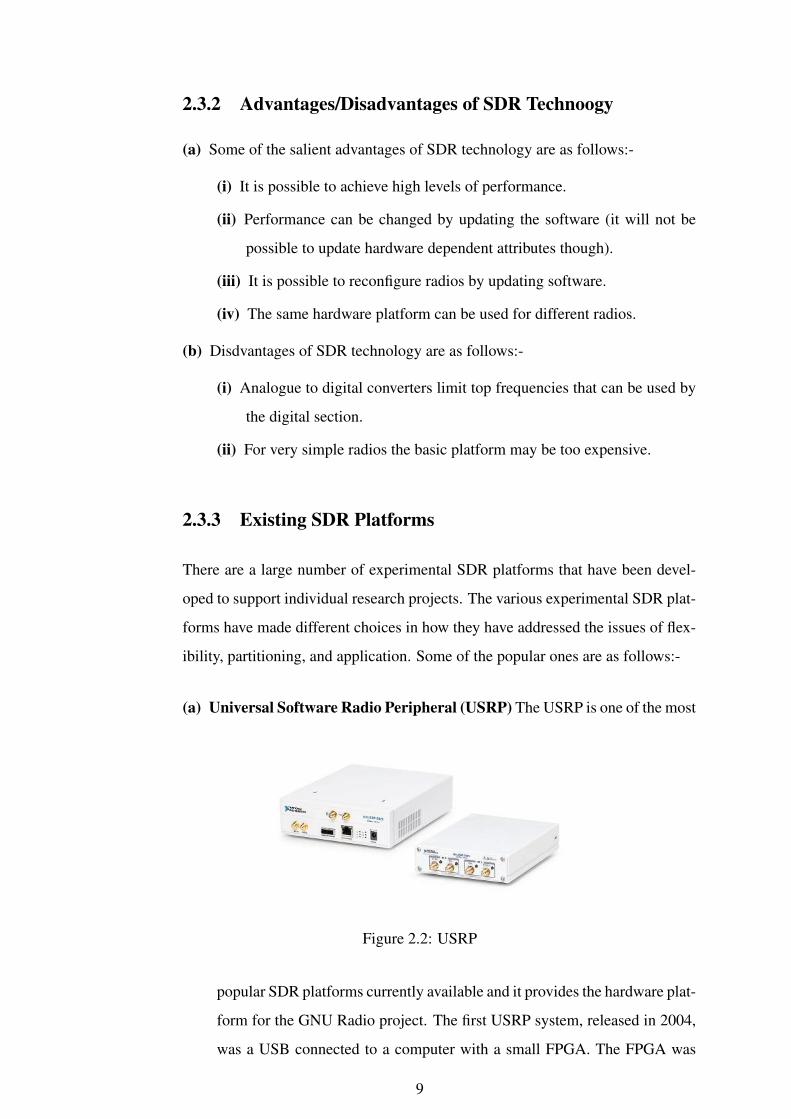
(a) Universal Software Radio Peripheral (USRP) The USRP is one of the most
Figure 2.2: USRP
popular SDR platforms currently available and it provides the hardware plat-
form for the GNU Radio project. The first USRP system, released in 2004,
was a USB connected to a computer with a small FPGA. The FPGA was
9
not only used primarily for routing information but also allowed some lim-
ited signal processing. The USRP could realistically support about 3 MHz
of bandwidth primarily due to the performance restrictions of the USB in-
terface. The second generation platform was released in September 2008
and utilizes gigabit Ethernet to allow support for 25 MHz of bandwidth.The
system includes a capable Xilinx Spartan3 device which allows for local
processing. The radio-frequency performance of the USRP is limited and is
more directed toward experimentation rather than matching any communi-
cations standard.
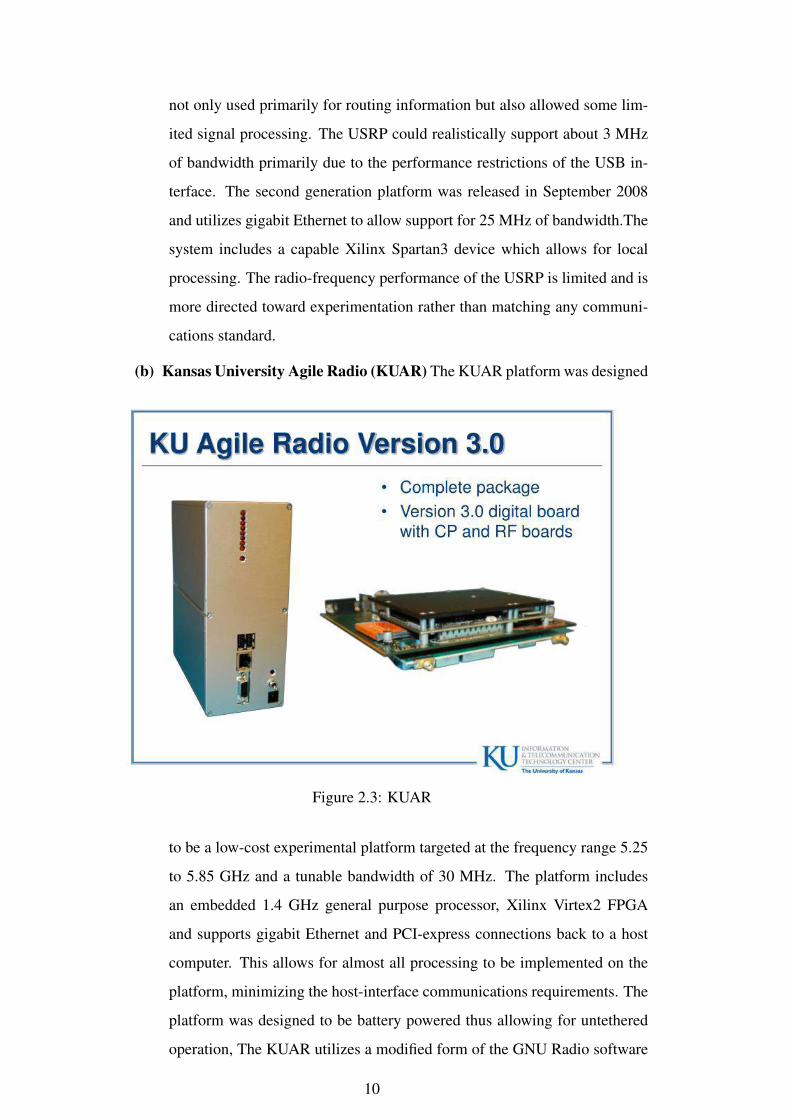
(b) Kansas University Agile Radio (KUAR) The KUAR platform was designed
Figure 2.3: KUAR
to be a low-cost experimental platform targeted at the frequency range 5.25
to 5.85 GHz and a tunable bandwidth of 30 MHz. The platform includes
an embedded 1.4 GHz general purpose processor, Xilinx Virtex2 FPGA
and supports gigabit Ethernet and PCI-express connections back to a host
computer. This allows for almost all processing to be implemented on the
platform, minimizing the host-interface communications requirements. The
platform was designed to be battery powered thus allowing for untethered
operation, The KUAR utilizes a modified form of the GNU Radio software
10

framework to complete the hardware platform.
(c) NICT SDR Platform The Japanese National Institute of Information and
Figure 2.4: NICT SDR
Communications Technology (NICT) constructed a SDR platform for trial
of next generation mobile networks. The platform has two embedded pro-
cessors, four Xilinx Virtex2 FPGA, and RF modules that could support 1.9
to 2.4 and 5.0 to 5.3 GHz. The signal processing was partitioned between
the CPU and the FPGA, with the CPU taking responsibility for the higher
layers. An objective of this platform was to explore selection algorithms
to manage handover between existing standards. To this end, a number of
commercial standards were implemented, for example, 802.11a/b/g, digital
terrestrial broadcasting (Japanese format), WCDMA, and a general OFDM
communication scheme.
(d) Berkeley Cognitive Radio Platform This platform is based around the Berke-
ley emulation engine (BEE2) which is a platform that contains five high-
powered Virtex2 FPGAs and can connect up to eighteen daughterboards. In
the Cognitive Radio Platform, radio daughterboards have been designed to
support up to 25 MHz of bandwidth in an 85 MHz range in the 2.4 GHz ISM
Band. The RF modules have highly sensitive receivers and to avoid self-
generated noise operate either concurrently at different frequencies (FDD)
or at the same frequency in time-division duplex (TDD) mode. This cogni-
tive radio platform requires only a low-bandwidth connection to a support-
ing PC as all signal processing is performed on the platform.
(e) Maynooth Adaptable Radio System The Maynooth adaptable radio system
11
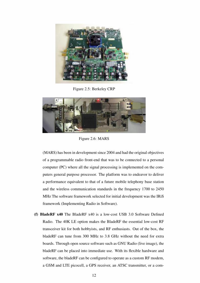
Figure 2.5: Berkeley CRP
Figure 2.6: MARS
(MARS) has been in development since 2004 and had the original objectives
of a programmable radio front-end that was to be connected to a personal
computer (PC) where all the signal processing is implemented on the com-
puters general purpose processor. The platform was to endeavor to deliver
a performance equivalent to that of a future mobile telephony base station
and the wireless communication standards in the frequency 1700 to 2450
MHz The software framework selected for initial development was the IRiS
framework (Implementing Radio in Software).
(f) BladeRF x40 The BladeRF x40 is a low-cost USB 3.0 Software Defined
Radio. The 40K LE option makes the BladeRF the essential low-cost RF
transceiver kit for both hobbyists, and RF enthusiasts. Out of the box, the
bladeRF can tune from 300 MHz to 3.8 GHz without the need for extra
boards. Through open source software such as GNU Radio (live image), the
bladeRF can be placed into immediate use. With its flexible hardware and
software, the bladeRF can be configured to operate as a custom RF modem,
a GSM and LTE picocell, a GPS receiver, an ATSC transmitter, or a com-
12

Figure 2.7: BladeRF
bination Bluetooth/Wi-Fi client, without the need for any expansion cards.
All of the bladeRF host software, firmware, and HDL is open source, and
available on GitHub.
It was decided to use BladeRF x40 as the SDR as part of our project.
2.4 Single Board Computer (SBC)
Figure 2.8: SBC
(a) A single-board computer (SBC) is built on a single circuit board and contains func-
tional computer components including the microprocessor, input/output (I/O) and
13

memory. SBC computers typically provide a fan-less, low-power computing so-
lution and a low profile architecture. Right from the mobile phone in your pockets
to high end gaming consoles, including tablets, PCs, iPod, etc, everything is ba-
sically a single board computer.
(b) There is a difference between traditional computers and single board computers.
Full-fledged computers (like PCs and Mac) have a motherboard. On the moth-
erboard, we will essentially find a processor (like the Intel R© CoreTM, AMD R©
AthlonTM, etc.), and other circuitry associated with that. We will also find slots
for other peripherals like RAM, ROM, Hard Disk, LAN Card, CPU Fan, Heat
Sink, LCD monitor, etc. These peripherals need to be attached to the mother-
board separately in order to make the PC/Mac fully functional.
(c) However, Single board computers consist of everything on a single board itself. On
the board, we have a processor and all other necessary peripherals and circuitry as
well. We have onboard RAM, ROM, flash storage, AV ports, Ethernet port, etc.
This means that one board is sufficient to act as a full-fledged computer. They can
boot into an operating system (OS) like Linux, Android, etc. and operate like any
other computer. Being lightweight and specific, they have found huge application
in smartphones, tablets and other consumer products with specific application
based requirements.
(d) These single board computers are not as powerful as the current day PCs, laptops
or Mac, and hence do not dissipate much heat. In addition to that, the processors
are designed in order to generate less heat and consume less power.
(e) There are several reasons one might opt to use a single board computer as mentioned
below:-
(i) Portability It being one of the major features. One can carry around a small
computer like smartphone in the pocket everywhere one goes. These devices
are pretty intuitive to use as well.
(ii) Power They consume less power and energy as compared to traditional com-
puters.
(iii) Cost The most attractive feature is being cost effective. This makes them
suitable for developer applications as well for development of new apps,
14
testing, debugging, hardware development,etc.
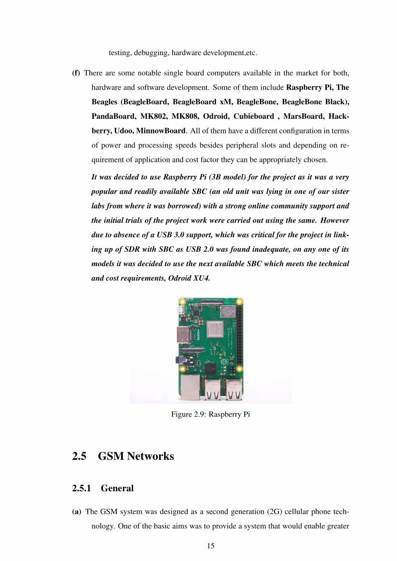
(f) There are some notable single board computers available in the market for both,
hardware and software development. Some of them include Raspberry Pi, The
Beagles (BeagleBoard, BeagleBoard xM, BeagleBone, BeagleBone Black),
PandaBoard, MK802, MK808, Odroid, Cubieboard , MarsBoard, Hack-
berry, Udoo, MinnowBoard. All of them have a different configuration in terms
of power and processing speeds besides peripheral slots and depending on re-
quirement of application and cost factor they can be appropriately chosen.
It was decided to use Raspberry Pi (3B model) for the project as it was a very
popular and readily available SBC (an old unit was lying in one of our sister
labs from where it was borrowed) with a strong online community support and
the initial trials of the project work were carried out using the same. However
due to absence of a USB 3.0 support, which was critical for the project in link-
ing up of SDR with SBC as USB 2.0 was found inadequate, on any one of its
models it was decided to use the next available SBC which meets the technical
and cost requirements, Odroid XU4.
Figure 2.9: Raspberry Pi
2.5 GSM Networks
2.5.1 General
(a) The GSM system was designed as a second generation (2G) cellular phone tech-
nology. One of the basic aims was to provide a system that would enable greater
15
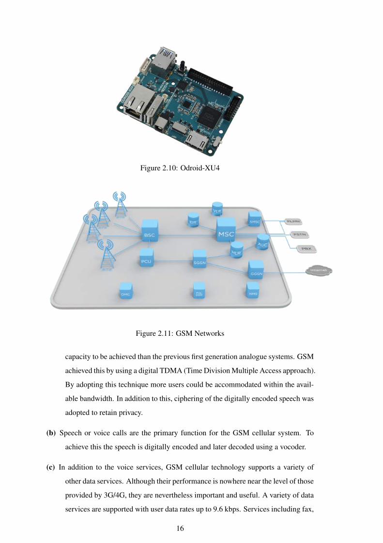
Figure 2.10: Odroid-XU4
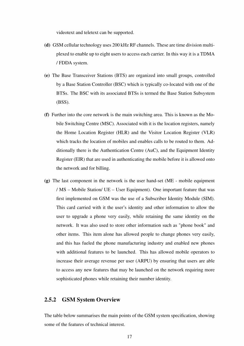
Figure 2.11: GSM Networks
capacity to be achieved than the previous first generation analogue systems. GSM
achieved this by using a digital TDMA (Time Division Multiple Access approach).
By adopting this technique more users could be accommodated within the avail-
able bandwidth. In addition to this, ciphering of the digitally encoded speech was
adopted to retain privacy.
(b) Speech or voice calls are the primary function for the GSM cellular system. To
achieve this the speech is digitally encoded and later decoded using a vocoder.
(c) In addition to the voice services, GSM cellular technology supports a variety of
other data services. Although their performance is nowhere near the level of those
provided by 3G/4G, they are nevertheless important and useful. A variety of data
services are supported with user data rates up to 9.6 kbps. Services including fax,
16
videotext and teletext can be supported.
(d) GSM cellular technology uses 200 kHz RF channels. These are time division multi-
plexed to enable up to eight users to access each carrier. In this way it is a TDMA
/ FDDA system.
(e) The Base Transceiver Stations (BTS) are organized into small groups, controlled
by a Base Station Controller (BSC) which is typically co-located with one of the
BTSs. The BSC with its associated BTSs is termed the Base Station Subsystem
(BSS).
(f) Further into the core network is the main switching area. This is known as the Mo-
bile Switching Centre (MSC). Associated with it is the location registers, namely
the Home Location Register (HLR) and the Visitor Location Register (VLR)
which tracks the location of mobiles and enables calls to be routed to them. Ad-
ditionally there is the Authentication Centre (AuC), and the Equipment Identity
Register (EIR) that are used in authenticating the mobile before it is allowed onto
the network and for billing.
(g) The last component in the network is the user hand-set (ME - mobile equipment
/ MS – Mobile Station/ UE – User Equipment). One important feature that was
first implemented on GSM was the use of a Subscriber Identity Module (SIM).
This card carried with it the user’s identity and other information to allow the
user to upgrade a phone very easily, while retaining the same identity on the
network. It was also used to store other information such as "phone book" and
other items. This item alone has allowed people to change phones very easily,
and this has fueled the phone manufacturing industry and enabled new phones
with additional features to be launched. This has allowed mobile operators to
increase their average revenue per user (ARPU) by ensuring that users are able
to access any new features that may be launched on the network requiring more
sophisticated phones while retaining their number identity.
2.5.2 GSM System Overview
The table below summarises the main points of the GSM system specification, showing
some of the features of technical interest.
17

Specifications Details
Multiple access technology FDMA / TDMADuplex technique FDDUplink frequency band 890-915 MHz(basic 900 MHz band only)Downlink frequency band 933-960 MHz(basic 900 MHz band only)Channel spacing 200KHzModulation GMSKSpeech coding Various - original was RPE-LTP/13Speech channels per RF channel 8Channel data rate 270.833KbpsFrame duration 4.615
Table 2.1: GSM Specifications
2.5.3 GSM Network Architecture
It can be grouped into four main areas:
(a) Network and Switching Subsystem (NSS)
(b) Base-Station Subsystem (BSS)
(c) Mobile station (MS)
(d) Operation and Support Subsystem (OSS)
2.6 Open source GSM Implementation
(a) A number of commercial and open source software options are available online for
GSM network implementation to establish a small GSM network with a limited
range by configuring the various sub-systems of GSM architecture, as explained
above, in the software domain and integrating an omnidirectional / directive radio
for necessary transmission and reception.
(b) Some of the available different options that were read and examined are as follows:-
(i) OpenBTS (Open Base Transceiver Station)
(ii) OsmocomBB.
(iii) YateBTS.
18
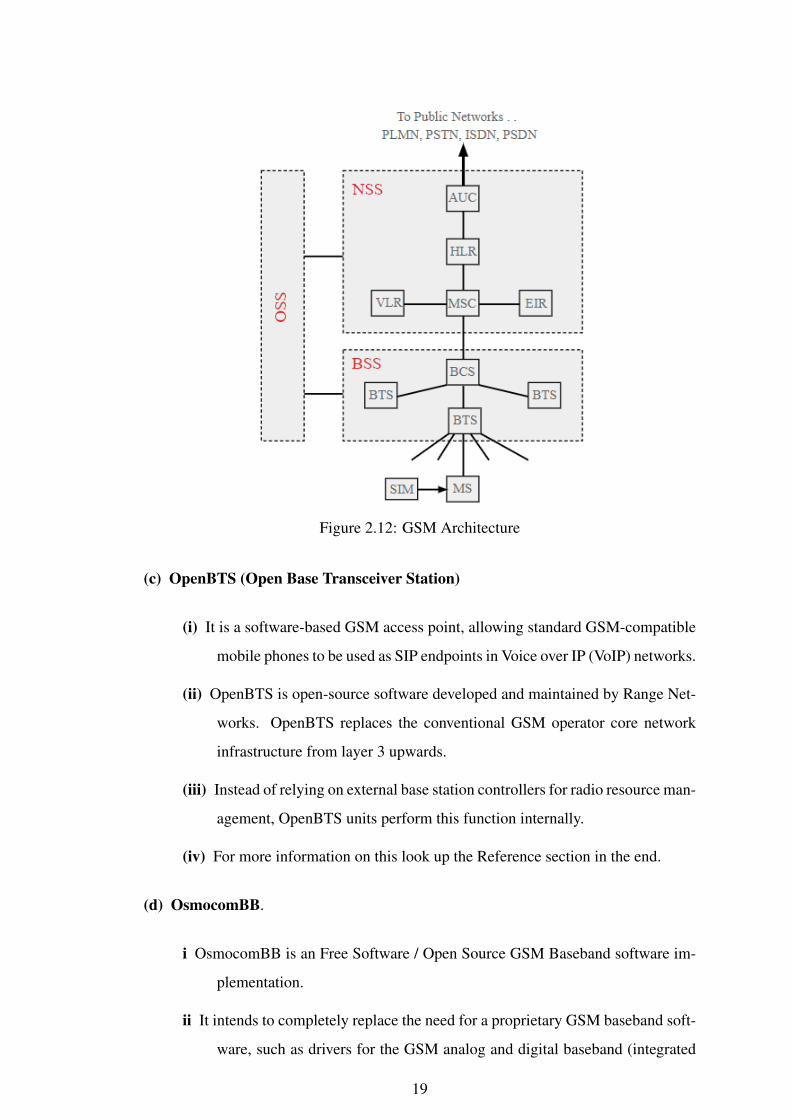
Figure 2.12: GSM Architecture
(c) OpenBTS (Open Base Transceiver Station)
(i) It is a software-based GSM access point, allowing standard GSM-compatible
mobile phones to be used as SIP endpoints in Voice over IP (VoIP) networks.
(ii) OpenBTS is open-source software developed and maintained by Range Net-
works. OpenBTS replaces the conventional GSM operator core network
infrastructure from layer 3 upwards.
(iii) Instead of relying on external base station controllers for radio resource man-
agement, OpenBTS units perform this function internally.
(iv) For more information on this look up the Reference section in the end.
(d) OsmocomBB.
i OsmocomBB is an Free Software / Open Source GSM Baseband software im-
plementation.
ii It intends to completely replace the need for a proprietary GSM baseband soft-
ware, such as drivers for the GSM analog and digital baseband (integrated
19

and external) peripherals, GSM phone-side protocol stack, from layer 1 up
to layer 3.
iii For more information on this look up the Reference section in the end.
(e) YateBTS.
(i) It is a software implementation of a GSM/GPRS radio access network
based on Yate .
(ii) It is compatible with both GSM/GPRS SS7 MAP and LTE IMS core net-
works integrated in our YateUCN unified core network server.
(iii) YateBTS offers a unique approach, different from that of traditional radio ac-
cess networks, with increased flexibility, scalability and is easily upgradable
with new features. It has two parts, MBTS (Lower layer) that handles GSM
aspects and connects to radio transceiver using socket interface, Network
layer that carries out the network support and connectivity.
(iv) YATE (Yet Another Telephony Engine) supports Voice, data, video and IM.
It is written in C++ and licensed under GNU GP License.
(v) For more information on this look up the reference section in the end.
It was decided to use Yate/YateBTS as the open source software implementa-
tion on Odroid XU4 (SBC) as part of our project as it has an open and active
online community forum and implementation codes are more comprehensive
and easier to understand. The code for implementation was directly written on
Linux after loading the necessary files/updates through interface commands as
explained in later chapters.
2.7 IEEE 802.11 standard (Wi-Fi and WLAN)
(a) IEEE 802.11 refers to the set of standards that define communication for wireless
LANs (wireless local area networks, or WLANs). The technology behind 802.11
is branded to consumers as Wi-Fi.
(b) IEEE 802.11 is overseen by the IEEE, IEEE LAN/MAN Standards Committee
(IEEE 802). The current version of the standard is IEEE 802.11-2007.
20

Figure 2.13: WiFi
(c) IEEE 802.11 is the set of technical guidelines for implementing Wi-Fi. Selling
products under this trademark is overseen by an industry trade association by the
name of the Wi-Fi Alliance. There is only one standard (IEEE 802.11-2007) but
many amendments. Commonly known amendments include 802.11a, 802.11b,
802.11g, and 802.11n. By releasing updated variants, the overall technology has
been able to keep pace with the ever growing requirements for more data and
higher speeds, etc.
(d) Wi-Fi wireless connectivity is an established part of everyday life. All smartphones
have it incorporated into the phone enabling low cost connectivity to be provided.
In addition to this, computers, laptops, tablets, cameras and many other devices
use Wi-Fi including many Internet of Things (IoT) sensors and nodes.
(e) There are two types of WLAN network that can be formed using a WiFi system:-
(i) Infrastructure networks The infrastructure application is aimed at office ar-
eas or to provide a "hotspot". The WLAN equipment can be installed in-
stead of a wired system, and can provide considerable cost savings, espe-
cially when used in established offices. A backbone wired network is still
required and is connected to a server. The wireless network is then split up
into a number of cells, each serviced by or Access Point (AP) which acts as
a controller for the cell. Each Access Point may have a range of between
30 and 300 metres dependent upon the environment and the location of the
Access Point.
(ii) Ad-hoc networks These are formed when a number of computers and pe-
ripherals are brought together. They may be needed when several people
21
come together and need to share data or if they need to access a shared
printer without the need for having to use wire connections. In this situa-
tion the users only communicate with each other and not with a larger wired
network. As a result there is no Access Point and special algorithms within
the protocols are used to enable one of the peripherals to take over the role
of master to control the network with the others acting as slaves.
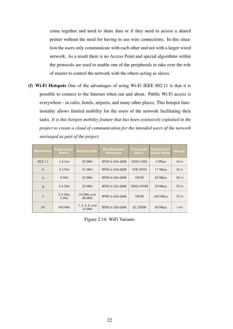
(f) Wi-Fi Hotspots One of the advantages of using Wi-Fi IEEE 802.11 is that it is
possible to connect to the Internet when out and about. Public Wi-Fi access is
everywhere - in cafes, hotels, airports, and many other places. This hotspot func-
tionality allows limited mobility for the users of the network facilitating their
tasks. It is this hotspot mobility feature that has been extensively exploited in the
project to create a cloud of communication for the intended users of the network
envisaged as part of the project.
Figure 2.14: WiFi Variants
22
CHAPTER 3
PROVIDING COMMUNICATION IN AREAS WITH
NO COMMUNICATION INFRASTRUCTURE IN THE
VICINITY (SCENARIO 2)
3.1 Modules
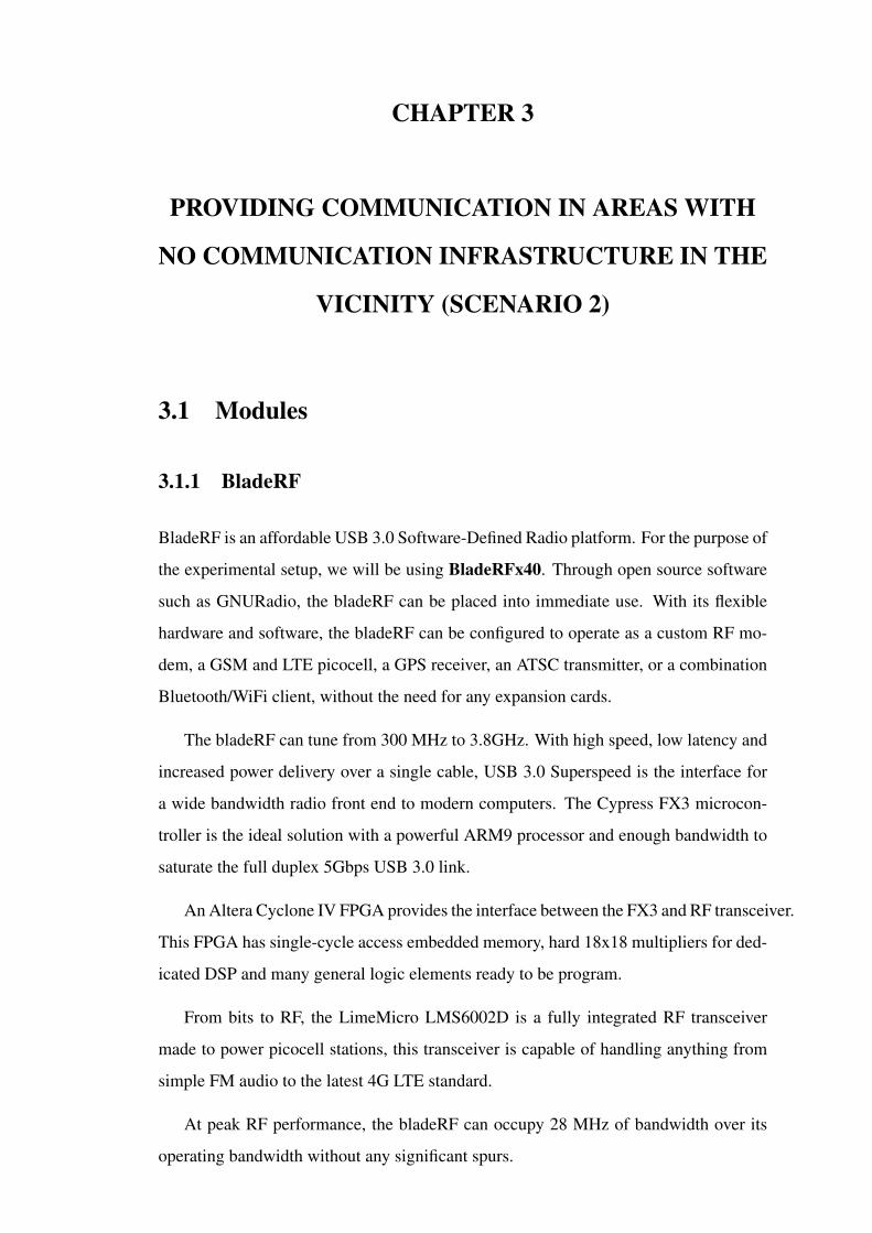
3.1.1 BladeRF
BladeRF is an affordable USB 3.0 Software-Defined Radio platform. For the purpose of
the experimental setup, we will be using BladeRFx40. Through open source software
such as GNURadio, the bladeRF can be placed into immediate use. With its flexible
hardware and software, the bladeRF can be configured to operate as a custom RF mo-
dem, a GSM and LTE picocell, a GPS receiver, an ATSC transmitter, or a combination
Bluetooth/WiFi client, without the need for any expansion cards.
The bladeRF can tune from 300 MHz to 3.8GHz. With high speed, low latency and
increased power delivery over a single cable, USB 3.0 Superspeed is the interface for
a wide bandwidth radio front end to modern computers. The Cypress FX3 microcon-
troller is the ideal solution with a powerful ARM9 processor and enough bandwidth to
saturate the full duplex 5Gbps USB 3.0 link.
An Altera Cyclone IV FPGA provides the interface between the FX3 and RF transceiver.
This FPGA has single-cycle access embedded memory, hard 18x18 multipliers for ded-
icated DSP and many general logic elements ready to be program.
From bits to RF, the LimeMicro LMS6002D is a fully integrated RF transceiver
made to power picocell stations, this transceiver is capable of handling anything from
simple FM audio to the latest 4G LTE standard.
At peak RF performance, the bladeRF can occupy 28 MHz of bandwidth over its
operating bandwidth without any significant spurs.
S.No. Details
1 Frequency Range 300 MHz to 3.8 GHz2 USB 3.0 superspeed SDR3 Integrated Lime Micro LMS6002D4 FPGA Altera Cyclone IV5 Power Supply 5V ,3 Amps DC input6 Independent Rx and TxSignals Paths7 Expansion Port with 32 I/O Pins • JTAG connectors • SMB Con-
nectors for MIMO configurations • Triggered multi-device samplingsynchronization
8 Antennas Omnidirectional Duct Antennas( 700 to 2600 MHz)9 Weight 80 grams10 Dimensions 8.7 x 13.8 x 1.8 inches)11 Upto 28 MHz of instantaneous BW • Software select-able filter option
from 1.5 MHz to 28 MHz
Table 3.1: BladeRF x40 Specifications
The technical specifications of BladeRF x40 are as follows:-
Figure 3.1: BladeRF.
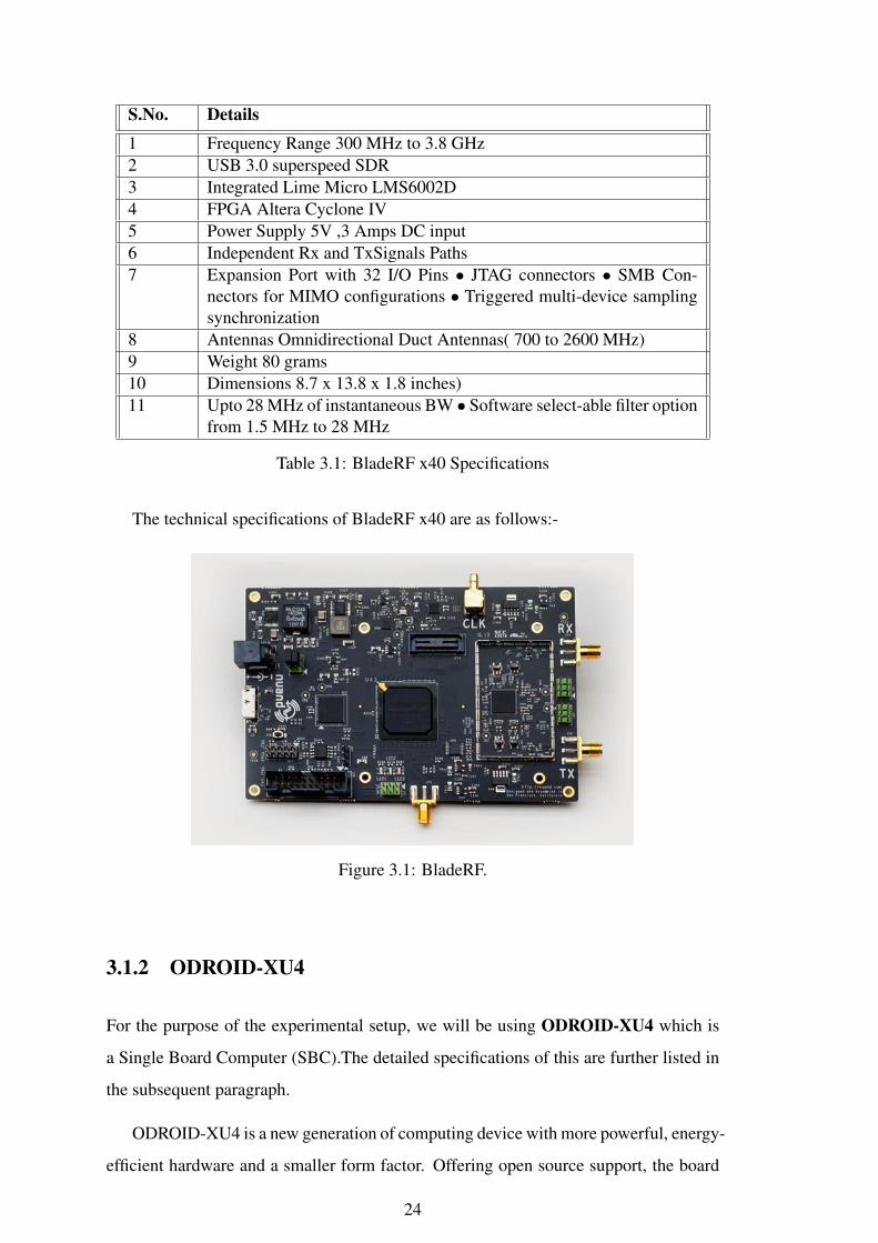
3.1.2 ODROID-XU4
For the purpose of the experimental setup, we will be using ODROID-XU4 which is
a Single Board Computer (SBC).The detailed specifications of this are further listed in
the subsequent paragraph.
ODROID-XU4 is a new generation of computing device with more powerful, energy-
efficient hardware and a smaller form factor. Offering open source support, the board
24

can run various flavors of Linux, including the latest Ubuntu 16.04.
Figure 3.2: Odroid-XU4.
25
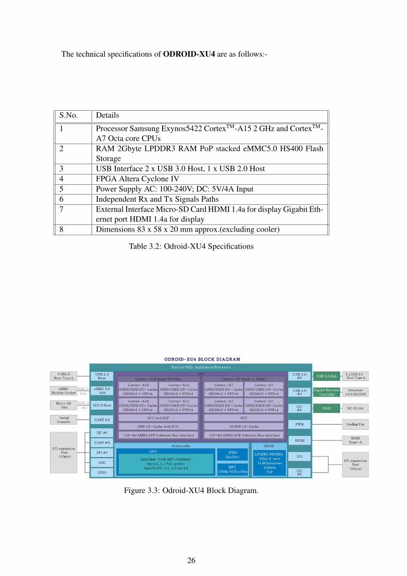
The technical specifications of ODROID-XU4 are as follows:-
S.No. Details
1 Processor Samsung Exynos5422 CortexTM-A15 2 GHz and CortexTM-A7 Octa core CPUs
2 RAM 2Gbyte LPDDR3 RAM PoP stacked eMMC5.0 HS400 FlashStorage
3 USB Interface 2 x USB 3.0 Host, 1 x USB 2.0 Host4 FPGA Altera Cyclone IV5 Power Supply AC: 100-240V; DC: 5V/4A Input6 Independent Rx and Tx Signals Paths7 External Interface Micro-SD Card HDMI 1.4a for display Gigabit Eth-
ernet port HDMI 1.4a for display8 Dimensions 83 x 58 x 20 mm approx.(excluding cooler)
Table 3.2: Odroid-XU4 Specifications
Figure 3.3: Odroid-XU4 Block Diagram.
26

3.1.3 Micro SD Card
For the purpose of the experimental setup, we will be using Sony 32 GB,Class
10SD card.
3.1.4 SD Card Reader
For the purpose of the experimental setup, we will be using Zebronics ZEB- 201CRcard
reader.
3.1.5 Power Supply
For the purpose of the experimental setup, we will be using 3 Cells,12 V, 1300mAh
battery.
Figure 3.4: Power Supply SetUp.
27

3.2 Experimental Set Up For Experiment 2A (Without
Using Drone)
The procedure to program specific experimental settings to execute the extension of
GSM network signals and involves the following steps:-
3.2.1 Setting Up Odroid-XU4
Setting Up Odroid XU4 To set up the Odroid system , we need to do the following
steps:-
Step 1. Go to https://wiki.odroid.com/odroid-xu4/os_images/linux/
ubuntu_4.14/ubuntu_4.14 and further download the operating system
image for XU4 from https://odroid.in/ubuntu_18.04lts/XU3_XU4_
MC1_HC1_HC2/ onto any desktop/laptop.
Step 2. Download Balena Etcher software on to desktop/laptop for flashing the
above downloaded OS image on to a card SD card.
Step 3. Insert an SD card to the desktop/laptop using the card reader and run the Balena
etcher sofware for flashing the OS image onto the SD card.
Step 4. Unmount the flashed SD card from the system and insert it to the SD card slot
of the Odroid XU4 system.
Step 5. Boot Up the system and update the system.
3.2.2 Setting Up BladeRF
To set up the BladeRF for Yate and YateBTS , we need to do the following steps:- Go to
home directory and create a folder “project” and a subfolder to it namely patch. In the
patch subfolder download the missing patch yatebts-gcc6-gcc7.patch from
the link https://gist.github.com/qingxp9/a250697ad9486897c3cbe20834bd6d44
In the project folder create a shell script “bladeInstall” with the commands as given be-
low:
28

#!/bin/bash
sudo apt update
sudo apt upgrade
sudo apt install git apache2 php
sudo apt install bladerf bladerf-firmware-fx3 bladerf-fpga-hostedx40 libbladerf1 automake libbladerf-dev
#sudo bladeRF-cli -i
sudo apt install subversion autoconf libusb-1.0-0-dev libgsm1-dev
sudo apt install g++ gcc
sudo apt install make
cd /usr/src/
sudo rm -rf /usr/src/yate*
sudo rm -rf /usr/local/etc/yate*
sudo svn checkout http://voip.null.ro/svn/yate/trunk yate
cd /usr/src/yate/
sudo svn up
sudo ./autogen.sh
sudo ./configure
sudo make -j4
sudo make install-noapi
sudo ldconfig
cd /usr/src/
sudo svn checkout http://voip.null.ro/svn/yatebts/trunk yatebts
cd /usr/src/yatebts
sudo svn up
sudo ./autogen.sh
sudo ./configure
ver=$(gcc --version|grep "gcc"|awk ’{print $NF}’|cut -f1 -d’.’)
if [ $ver -gt 5 ]; then
echo "GCC version $ver is higher than 5.0."
read -p "Input path to patch file" patchPath
if [ -s "$patchPath" ]; then
if [[ $(sudo svn patch --strip 1 --dry-run "$patchPath") ]]; then
sudo svn patch --strip 1 "$patchPath"
29

else
echo Check patch file. Restart script.
exit 1;
fi
else
echo Invalid Path. Restart the script.
exit 1;
fi
fi
sudo make install
sudo ldconfig
if [ -d /usr/local/share/yate/nipc_web ];then
echo NIPC_WEB Folder created.
else
sudo mkdir -p /usr/local/share/yate/nipc_web
echo NIPC_WEB Folder created.
fi
if [ -d /var/www/html/ ];then
echo html Folder created.
else
sudo mkdir -p /var/www/html
echo html Folder created.
fi
sudo ln -sf /usr/local/share/yate/nipc_web /var/www/html/nipc
sudo chmod -R a+w /usr/local/etc/yate/
sudo chmod 777 /usr/src/yate
sudo chmod 777 /usr/src/yatebts
echo "Install completed"
Open the terminal and got to the directory where the shell script as given above has
been created. Give the shell script executable permissions using sudo chmod u+x
bladeInstall and then run the following command sudo bladeInstall to
install the setup. Restart the system once installation is complete.
30

3.2.3 Setting Up Parameters For Yate and YateBTS
To set up the Yate and YateBTS parameter, connect the bladeRF to the Odroid system
using USB3.0 cable on to the USB 3.0 port of Odroid XU4. Further we need to do
the following steps:- Open the file usrlocal/etc/yate/ybts.conf and set the
following parameters:
Radio.Band=900
Radio.C0=91
Identity.MCC=001
Identity.MNC=01
Radio.PowerManager.MaxAttenDB=10
Radio.PowerManager.MinAttenDB=0
MinimumRxRSSI=-105
Radio.RSSITarget=-26
Open the file usrlocal/etc/yate/ybts.conf and set the following parameters:
country_code=91
regexp=.*
3.2.4 Connecting the Mobile Handsets To The Network
To connect the mobile handsets to the network, we need to do the following steps:-
Step 1. Open the terminal and run the command sudo yate -s. This will start the
yateBTS and it will create a GSM network.
Step 2. Open the network setting of the mobile handset and change the automatic se-
lection of the network to manual. It will show the list of the available networks.
Step 3. Select the network of the YateBTS. Once done the mobile will get registered
on the network and an SMS will be received on the mobile giving out the new
registered mobile number. This number can then be used for calling or forwarding
SMS on to other mobile numbers in the same network.
31

3.3 Experimental Set Up For Experiment 2B (Using Drone)
It includes the procedure wherein the setup of the Experiment 2A is mounted on a drone
and the similar experiment as Experiment No 2A is carried out while drone is hovering
over an area to execute the extension of GSM network signals. The flight/hovering of
drone though forms an important part of the setup , however will not be analysed for its
control/manouvre as part of this experiment.
3.4 Experiment 2A/2B
(a) Once the handset is connected to the GSM network, start moving the handset away
from the YateBTS and note reading of the RSSI, ASU, Power in the Network Cell
Info Lite application (downloaded earlier in the handset) at regular intervals and
observe the change in the values.
(b) The connected mobile sets can be used to make calls, send SMS as done using
regular phones in commercial GSM networks.
Figure 3.5: Experiment 2 SetUp.
32
CHAPTER 4
PERFORMANCE ANALYSIS
4.1 General
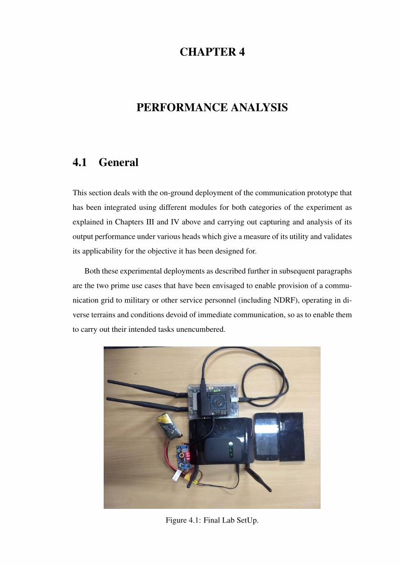
This section deals with the on-ground deployment of the communication prototype that
has been integrated using different modules for both categories of the experiment as
explained in Chapters III and IV above and carrying out capturing and analysis of its
output performance under various heads which give a measure of its utility and validates
its applicability for the objective it has been designed for.
Both these experimental deployments as described further in subsequent paragraphs
are the two prime use cases that have been envisaged to enable provision of a commu-
nication grid to military or other service personnel (including NDRF), operating in di-
verse terrains and conditions devoid of immediate communication, so as to enable them
to carry out their intended tasks unencumbered.
Figure 4.1: Final Lab SetUp.
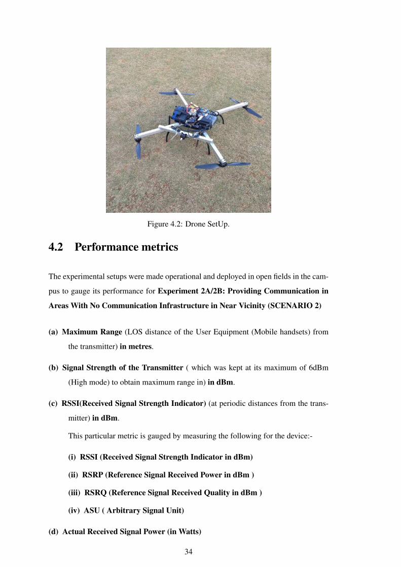
Figure 4.2: Drone SetUp.
4.2 Performance metrics
The experimental setups were made operational and deployed in open fields in the cam-
pus to gauge its performance for Experiment 2A/2B: Providing Communication in
Areas With No Communication Infrastructure in Near Vicinity (SCENARIO 2)
(a) Maximum Range (LOS distance of the User Equipment (Mobile handsets) from
the transmitter) in metres.
(b) Signal Strength of the Transmitter ( which was kept at its maximum of 6dBm
(High mode) to obtain maximum range in) in dBm.
(c) RSSI(Received Signal Strength Indicator) (at periodic distances from the trans-
mitter) in dBm.
This particular metric is gauged by measuring the following for the device:-
(i) RSSI (Received Signal Strength Indicator in dBm)
(ii) RSRP (Reference Signal Received Power in dBm )
(iii) RSRQ (Reference Signal Received Quality in dBm )
(iv) ASU ( Arbitrary Signal Unit)
(d) Actual Received Signal Power (in Watts)
34

4.3 Performance Metrics Explained
4.3.1 Range
It refers to the maximum straight line LOS distance (in metre) between the transmitter
and the UE for the established call to remain intelligible and without interruption.
4.3.2 Signal Strength of the Transmitter
The power of the transmitter (D-Link DIR-615 Wireless N-300 Router and Nuand
BladeRF x40) has been set to their maximum permitted value for the experiment and
are transmitting at 20dBm and 6 dBm respectively. Therefore this metric remains con-
stant for both experiments.
4.3.3 RSSI (Received Signal Strength Indicator in dBm)
RSSI is a measurement of the power present in a received radio signal.It is usually in-
visible to a user of a receiving device.However, because signal strength can vary greatly
and affect functionality in wireless networking, devices often make this measurement
available to users.
4.3.4 RSRP (Reference Signal Received Power in dBm )
RSRP is a measurement of the received power level in an LTE network. This measures
the power received from a single reference signal
4.3.5 RSRQ (Reference Signal Received Quality in dB )
RSRQ can be defined as RSRQ=[[N*RSRP]/RSSI] ,where N is . Also, RSRQ(dB)
= RSRP(dBm)-RSSI(dBm)
RSRQ is a calculated value from RSRP and RSSI is measure of signal and inter-
ference. As RSRQ is a ration of two signal powers with same same unit i.e. dBm so
RSRQ uses dB as a measurement unit.
35

4.3.6 ASU ( Arbitrary Signal Unit)
Arbitrary Strength Unit (ASU) is an integer value proportional to the received sig-
nal strength measured by the mobile phone. In GSM networks, ASU maps to RSSI
vide the following calculation: dBm = 2xASU-113, ASU in the range of
0.31 and 99.
4.3.7 Link Speed
It measures the quality of the link through the rate of data exchange between the trans-
mitter and the UE .
4.4 EXPERIMENT 2A: PROVIDING COMMUNICA-
TION IN AREAS WITH NO COMMUNICATION
INFRASTRUCTURE IN NEAR VICINITY USING
A STATIC PLATFORM (SCENARIO 2)
Figure 4.3: Concept For Experiment 2A.
36

Figure 4.4: SetUp For Experiment 2A.
4.4.1 General
The setup for this experiment, as explained in paragraph 4.2 above, was initially es-
tablished at the roof top of Engineering Design (ED) Department building in one cor-
ner overlooking the “Chemplast cricket grounds” and subsequently on the roof top of
Biotechnology Department Building overlooking the fields of Hockey, Football and
Cricket grounds. This provided a clear view and LOS for the measurements to be car-
ried out. The setup is as illustrated below followed by pictures of the site/setup to
appreciate the general layout.
4.4.2 Experimental Readings
The experimental reading of Experiment 2A are as follows:-
S.No. Details Readings
1 Date 29 Apr 20192 TOD 0700-1000h3 Temp 32 Degree C4 Duration 3 hours5 General Location Biotechnology Building Roof top and
Hockey, Football and Cricket grounds6 Tramsmitter Signal
Strength6dBm
Table 4.1: Experiment 2A
37
S.No. Loc of Spot Distance RSSI(dBm)
LinkSpeed(Mbps)
CallQuality(MOS1-5)
1 Roof Top 1 -51 31 52 Football Field Half Line 110 -95 9 53 Cricket Ground # 1 Spot 113 -94.3 9 54 Football Field D/Top 135 -104 4 45 Cricket Ground # 2 Spot 143 -100.3 6 46 Football Field Goal Line 154 -104 4 47 Hockey Fielf Half Line 156 -106 3 38 Cricket Ground # 3 Spot 164 -105.4 3 39 Hockey Field Goal Line 187 -110 2 210 Cricket Ground Boundary
Line193 -107 3 2
11 Cricket Ground BeyondBoundary Line
203 -103 4 3
12 Cricket Ground BoundaryLine At Fence
213 -105.7 3 2
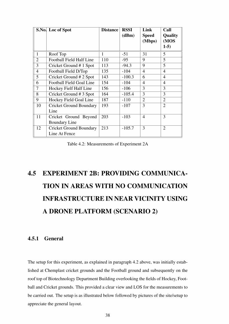
Table 4.2: Measurements of Experiment 2A
4.5 EXPERIMENT 2B: PROVIDING COMMUNICA-
TION IN AREAS WITH NO COMMUNICATION
INFRASTRUCTURE IN NEAR VICINITY USING
A DRONE PLATFORM (SCENARIO 2)
4.5.1 General
The setup for this experiment, as explained in paragraph 4.2 above, was initially estab-
lished at Chemplast cricket grounds and the Football ground and subsequently on the
roof top of Biotechnology Department Building overlooking the fields of Hockey, Foot-
ball and Cricket grounds. This provided a clear view and LOS for the measurements to
be carried out. The setup is as illustrated below followed by pictures of the site/setup to
appreciate the general layout.
38

Figure 4.5: Concept For Experiment 2B.
Figure 4.6: SetUp For Experiment 2B.
4.5.2 Experimental Readings
The experimental reading of Experiment 2B are as follows:-
Key Notes Experiment 2A & 2B
(a) The spikes in between a gradual decrease in signal strength with increasing distance
is on account of measureme nts done in 3 different fields having different LOS
conditions from the transmitter located on roof top of Biotech.
(b) The experimental readings tabled above are the most recent ones that were taken.
(c) The readings on each spot are actually an average of minimum 3 readings taken in
39

S.No. Details Readings
1 Date 30 Apr 20192 TOD 0700-1000h3 Temp 31 Degree C4 Duration 3 hours5 General Location Biotechnology Building Roof top and
Hockey, Football and Cricket grounds6 Tramsmitter Signal
Strength6dBm
Table 4.3: Experiment 2B
S.No. Loc of Spot Distance RSSI(dBm)
LinkSpeed(Mbps)
CallQuality(MOS1-5)
1 Roof Top 1 -53 30 52 Football Field Half Line 110 -96 9 53 Cricket Ground # 1 Spot 113 -97 8 54 Football Field D/Top 135 -105 4 45 Cricket Ground # 2 Spot 143 -106 3 36 Football Field Goal Line 154 -107 3 37 Hockey Fielf Half Line 156 -107 3 38 Cricket Ground # 3 Spot 164 -110 2 29 Hockey Field Goal Line 187 -112 1 110 Cricket Ground Boundary
Line193 -111 1 1
11 Cricket Ground BeyondBoundary Line
203 -110 2 2
12 Cricket Ground BoundaryLine At Fence
213 -111 1 1
Table 4.4: Measurements of Experiment 2B
and around that spot.
(d) A number of such like experiments were done for taking down the readings and
those are generally in the same range with minor variations.
40
CHAPTER 5
CONCLUSION
1 The setup envisaged, prototyped and demonstrated as part of the project A DRONE-
BASED COMMUNICATION SYSTEM FOR STRATEGIC AND PPDR AP-
PLICATION is the first step towards finding a working solution for addressing
the critical requirement of robust and reliable communication for the forces re-
sponding to a mission-critical and time-critical task of tactical or humanitarian
interest.
2 A sound, robust and adaptable communication grid is the mainstay for any operat-
ing forces in any kind of operation; failing which the intended results are not
commensurate to the efforts. Therefore such systems which address this core
need must be given due consideration and further evolved. It is imperative that
repeated trials of the system be carried out to understand and address its short-
comings and transform it into a fool-proof system.
3 In the project report and demonstration only limited capabilities have been show-
cased, however with proper industry involvement and backing, a more useful
and value-added system can be commercially developed, to meet domain specific
needs, incorporating many additional features of scaling in capacity and qual-
ity, HD video and audio capturing, enhanced VOIP capabilities, encryption and
self-destruct mechanisms.
4 There are certain limitations with the present setup as it is a base-model architecture
at the cheapest cost available viz
(a) The present GSM software engine YateBTS only supports two concurrent
calls ie four users, although more number of users can still be connected to
avail SMS service.
(b) The present battery pack provides limited power to handle the two experi-
mental setups and therefore is a limiting factor.
(c) A tether-less drone also has a limited flying time which affects the system
and its range, however a tethered drone does not have this problem and can
extend the operational time although it suffers from mobility issues.
(d) The limited power output of the SDR and the router coupled with omnidi-
rectional antennas limit the range which can be overcome by using a power
amplifier and more directive antennas depending on the requirement.
5 The issues mentioned in paragraphs above need to be tackled systematically by the
industry partner involved in developing a more effective and useful communica-
tion system that will come in handy to the operating forces and meet their specific
requirements without compromising on qualitative issues.
6 Aerial platforms based systems have tremendous advantages over static platforms
especially on grounds of mobility and portability. Drones are the next generation
platforms to be used for all kinds of services viz transport, delivery, weapons,
medical, communication etc and therefore need to be suitably developed to force-
multiply the service it needs to cater to. A stable platform makes a huge impact
on the quality of service and therefore is equally important.
6.7 A sound communication grid will enable the respective forces operating on ground,
be it military or non-military, to meet their intended objective in a more coordi-
nated manner and in a shorter time-frame. In most emergency situations it can
prove to be critical in minimizing the casualties of men and material alongside
collateral damage. Therefore such communication systems need to be given due
significance towards further and holistic development.
42
APPENDIX A
WEIGHTS OF VARIOUS HARDWARE USED IN THE
PROJECT
(a) JioFi Dongle 100gms.
(b) D-Link DIR 615 Router 210gms.
(c) ODROID-XU4 90gms.
(d) BladeRF 270gms.
(e) Battery Eliminator Circuit 42 gms.
(f) Bty (1300mAH) 125gms.
(g) Bty (6200mAH) 430gms.

APPENDIX B
LIST OF INSTALLATION COMMANDS FOR YATE
AND YATE BTS
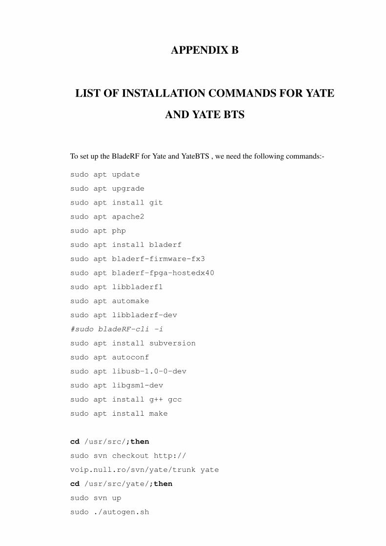
To set up the BladeRF for Yate and YateBTS , we need the following commands:-
sudo apt update
sudo apt upgrade
sudo apt install git
sudo apt apache2
sudo apt php
sudo apt install bladerf
sudo apt bladerf-firmware-fx3
sudo apt bladerf-fpga-hostedx40
sudo apt libbladerf1
sudo apt automake
sudo apt libbladerf-dev
#sudo bladeRF-cli -i
sudo apt install subversion
sudo apt autoconf
sudo apt libusb-1.0-0-dev
sudo apt libgsm1-dev
sudo apt install g++ gcc
sudo apt install make
cd /usr/src/;then
sudo svn checkout http://
voip.null.ro/svn/yate/trunk yate
cd /usr/src/yate/;then
sudo svn up
sudo ./autogen.sh

sudo ./configure
sudo make -j4
sudo make install-noapi
sudo ldconfig
cd /usr/src/;then
sudo svn checkout http://
voip.null.ro/svn/yatebts/trunk yatebts
cd /usr/src/yatebts;then
sudo svn up
sudo ./autogen.sh
sudo ./configure
sudo make install
sudo ldconfig
cd /var/www/html/;then
sudo ln -s /usr/local/share/
yate/nipc_web nipc
sudo chmod -R a+w /usr/local/etc/yate/
46

APPENDIX C
PAPER SUBMITTED FOR TENCON 2019

IMPLEMENTATION OF A DRONE-BASEDCOMMUNICATION SYSTEM FOR
STRATEGIC AND PPDR APPLICATIONSNeeraj Sharma, Pranav Kumar Opal, R. David Koilpillai
Elec Engg Dept,IITM,Chennai 600036Email: [email protected], [email protected], [email protected]
Abstract—Our military forces, during operations aredeployed in some places devoid of any communicationwhich affects their efficiency on ground due to inadequatecoordination means. Also, many unforeseen emergencysituations (viz natural calamities, train accidents, forestfires or any large scale public congregation) warrantimmediate action by first responders ( Public Protectionand Disaster Relief-PPDR or Military personnel ) to bringthe situation under control to prevent any further lossof life or material. During such occasions, there is asudden increase in cellular traffic leading to its eventualchoking/breakdown of system. This paper proposes to offera temporary, easy and fast-to-setup GSM and Wi-fi basedcommunication system that addresses this communicationvoid to allow our forces (PPDR or Military) to carryout their intended tasks efficiently amidst a broken/nocommunication infrastructure in place.
I. INTRODUCTION
Fig. 1: Light-Weight SDR based Basestation.
In this work, we have demonstrated how Drones(Unmanned Aerial Vehicle) can create an ad-hoc com-munication support system that can be quickly deployedin inaccessible areas. These areas can be ones whichare, although, near well-established communication in-frastructure but due to dead zone deployment of forces(wherein either their transmitter or receiver or both areso placed that they lack either forward or backward con-nectivity or in many cases both of them) lacks adequateconnectivity from it or are areas that lack communicationinfrastructure altogether.
Fig. 2: Drone D-Point0 (Audaxus)Wingspan-2m.
In the first scenario, we have an area of operationof forces in dead ground where communication is tobe provided using the existing communication infras-tructure from a nearby area. In the second scenario,communication is to be provided in a remote, isolatedarea where no communication exists in near vicinity.Theadditional provision of spectrum sensing, incorporatedin the system, to detect free frequency bands to es-tablish interference-free communication for our setupalso serves an additional strategic advantage of detectingoccupied frequency bands as a measure of electronicsurveillance/sensing of enemy forces.
This proposed setup has applications outside themilitary strategic domain also, especially in areasaffected by natural or man-made calamities where thecommunication infrastructure has been damaged. It canbe suitably adapted to be used by disaster response forcesto operate for their coordination of Personnel Protectionand Disaster Relief (PPDR) tasks.
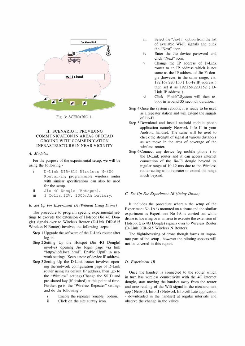
Fig. 3: SCENARIO 1.
II. SCENARIO 1: PROVIDINGCOMMUNICATION IN AREAS OF DEAD
GROUND WITH COMMUNICATIONINFRASTRUCTURE IN NEAR VICINITY
A. Modules
For the purpose of the experimental setup, we will beusing the following:-
i D-Link DIR-615 Wireless N-300Router,(any programmable wireless routerwith similar specifications can also be usedfor the setup.
ii Jio 4G Dongle (Hotspot).iii 3 Cells,12V, 1300mAh battery.
B. Set Up For Experiment 1A (Without Using Drone)
The procedure to program specific experimental set-tings to execute the extension of Hotspot (Jio 4G Don-gle) signals over to Wireless Router (D-Link DIR-615Wireless N Router) involves the following steps:-
Step 1 Upgrade the software of the D-Link router afterlog-in.
Step 2 Setting Up the Hotspot (Jio 4G Dongle)involves opening Jio login page via link“http://jiofi.local.html”. Enable UpnP in net-work settings. Keep a note of device IP address.
Step 3 Setting Up the D-Link router involves open-ing the network configuration page of D-Linkrouter using its default IP address.Then ,go tothe “Wireless” settings.Change the SSID andpre-shared key (if desired) at this point of time.Further, go to the “Wireless Repeater” settingsand do the following :-
i Enable the repeater ”enable” option.ii Click on the site survey icon.
iii Select the “Jio-Fi” option from the listof available Wi-Fi signals and clickthe “Next” icon.
iv Enter the Jio device password andclick “Next” icon.
v Change the IP address of D-Linkrouter to an IP address which is notsame as the IP address of Jio-Fi don-gle ,however, in the same range, viz,192.168.220.150 ( Jio-Fi IP address )then set it as 192.168.220.152 ( D-Link IP address ).
vi Click “Finish”.System will then re-boot in around 35 seconds duration.
Step 4 Once the system reboots, it is ready to be usedas a repeater station and will extend the signalsof Jio-Fi.
Step 5 Download and install android mobile phoneapplication namely Network Info II in yourAndroid handset. The same will be used tocheck the strength of signal at various distancesas we move in the area of coverage of thewireless router.
Step 6 Connect any device (eg mobile phone ) tothe D-Link router and it can access internetconnection of the Jio-Fi dongle beyond itsregular range of 10-12 mts due to the Wirelessrouter acting as its repeater to extend the rangemuch beyond.
C. Set Up For Experiment 1B (Using Drone)
It includes the procedure wherein the setup of theExperiment No 1A is mounted on a drone and the similarexperiment as Experiment No 1A is carried out whiledrone is hovering over an area to execute the extension ofHotspot (Jio 4G Dongle) signals over to Wireless Router(D-Link DIR-615 Wireless N Router).
The flight/hovering of drone though forms an impor-tant part of the setup , however the piloting aspects willnot be covered in this report.
D. Experiment 1B
Once the handset is connected to the router whichin turn has wireless connectivity with the 4G internetdongle, start moving the handset away from the routerand note reading of the Wifi signal in the measurementapp ( Network Info II / Network Info cell Lite application- downloaded in the handset) at regular intervals andobserve the change in the values.

Fig. 4: SCENARIO 2.
III. SCENARIO 2: PROVIDINGCOMMUNICATION IN AREAS WITH NO
COMMUNICATION INFRASTRUCTURE INNEAR VICINITY
A. Modules
For the purpose of the experimental setup, we will beusing
i BladeRF is an affordable USB 3.0 Software-Defined Radio platform. For the experimentalsetup, we use BladeRFx40.
ii We use ODROID XU4 which is an SingleBoard Computer (SBC).
iii A Sony 32 GB,Class 10SD card is used.Any SD card meeting these specifications canbe used for the setup.
iv We use Zebronics ZEB-201CR cardreader.
v 3 Cells,12V, 1300mAh battery.
B. Set Up For Experiment 2A (In Lab)
The procedure to program specific experimental set-tings to execute the extension of GSM network signalsand involves the following steps:- Setting Up OdroidXU4 To set up the Odroid system, we need to do thefollowing steps:-
Step 1 Go to https://wiki.odroid.com/odroid-xu4/osimages/linux/ubuntu 4.14/ubuntu 4.14 andfurther download the operating system imagefor XU4 from https://odroid.in/ubuntu 18.04lts/XU3 XU4 MC1 HC1 HC2/ onto anydesktop/laptop.
Step 2 Download Balena Etcher software on todesktop/laptop for flashing the above down-loaded OS image on to a card sd card.
Step 3 Insert an SD card to the desktop/laptop usingthe card reader and run the Balena etcher
sofware for flashing the OS image ontothe SDcard.
Step 4 Unmount the flashed SDcard from the systemand insert it to the SD card slot of the OdroidXU4 system.
Step 5 Boot Up the system and update the system.
C. Setting Up BladeRF
To set up the BladeRF for Yate and YateBTS , weneed the following commands:-
sudo apt updatesudo apt upgradesudo apt install gitsudo apt apache2sudo apt phpsudo apt install bladerfsudo apt bladerf-firmware-fx3sudo apt bladerf-fpga-hostedx40sudo apt libbladerf1sudo apt automakesudo apt libbladerf-dev#sudo bladeRF-cli -isudo apt install subversionsudo apt autoconfsudo apt libusb-1.0-0-devsudo apt libgsm1-devsudo apt install g++ gccsudo apt install make
cd /usr/src/;thensudo svn checkout http://voip.null.ro/svn/yate/trunk yatecd /usr/src/yate/;thensudo svn upsudo ./autogen.shsudo ./configuresudo make -j4sudo make install-noapisudo ldconfig
cd /usr/src/;thensudo svn checkout http://voip.null.ro/svn/yatebts/trunk yatebtscd /usr/src/yatebts;thensudo svn upsudo ./autogen.shsudo ./configuresudo make installsudo ldconfig
cd /var/www/html/;thensudo ln -s /usr/local/share/yate/nipc_web nipcsudo chmod -R a+w /usr/local/etc/yate/
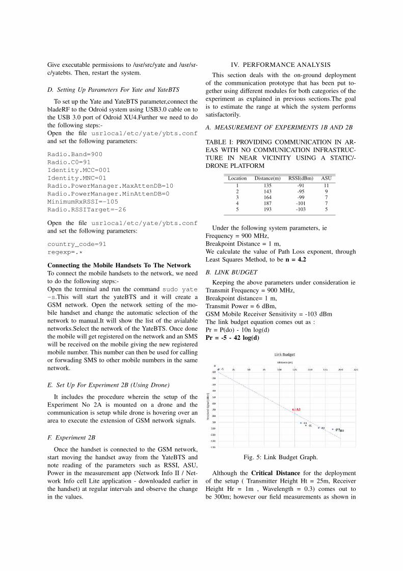
Give executable permissions to /usr/src/yate and /usr/sr-c/yatebts. Then, restart the system.
D. Setting Up Parameters For Yate and YateBTS
To set up the Yate and YateBTS parameter,connect thebladeRF to the Odroid system using USB3.0 cable on tothe USB 3.0 port of Odroid XU4.Further we need to dothe following steps:-Open the file usrlocal/etc/yate/ybts.confand set the following parameters:
Radio.Band=900Radio.C0=91Identity.MCC=001Identity.MNC=01Radio.PowerManager.MaxAttenDB=10Radio.PowerManager.MinAttenDB=0MinimumRxRSSI=-105Radio.RSSITarget=-26
Open the file usrlocal/etc/yate/ybts.confand set the following parameters:
country_code=91regexp=.*
Connecting the Mobile Handsets To The NetworkTo connect the mobile handsets to the network, we needto do the following steps:-Open the terminal and run the command sudo yate-s.This will start the yateBTS and it will create aGSM network. Open the network setting of the mo-bile handset and change the automatic selection of thenetwork to manual.It will show the list of the avialablenetworks.Select the network of the YateBTS. Once donethe mobile will get registered on the network and an SMSwill be received on the mobile giving the new registeredmobile number. This number can then be used for callingor forwading SMS to other mobile numbers in the samenetwork.
E. Set Up For Experiment 2B (Using Drone)
It includes the procedure wherein the setup of theExperiment No 2A is mounted on a drone and thecommunication is setup while drone is hovering over anarea to execute the extension of GSM network signals.
F. Experiment 2B
Once the handset is connected to the GSM network,start moving the handset away from the YateBTS andnote reading of the parameters such as RSSI, ASU,Power in the measurement app (Network Info II / Net-work Info cell Lite application - downloaded earlier inthe handset) at regular intervals and observe the changein the values.
IV. PERFORMANCE ANALYSIS
This section deals with the on-ground deploymentof the communication prototype that has been put to-gether using different modules for both categories of theexperiment as explained in previous sections.The goalis to estimate the range at which the system performssatisfactorily.
A. MEASUREMENT OF EXPERIMENTS 1B AND 2B
TABLE I: PROVIDING COMMUNICATION IN AR-EAS WITH NO COMMUNICATION INFRASTRUC-TURE IN NEAR VICINITY USING A STATIC/-DRONE PLATFORM
Location Distance(m) RSSI(dBm) ASU1 135 -91 112 143 -95 93 164 -99 74 187 -101 75 193 -103 5
Under the following system parameters, ieFrequency = 900 MHz,Breakpoint Distance = 1 m,We calculate the value of Path Loss exponent, throughLeast Squares Method, to be n = 4.2
B. LINK BUDGET
Keeping the above parameters under consideration ieTransmit Frequency = 900 MHz,Breakpoint distance= 1 m,Transmit Power = 6 dBm,GSM Mobile Receiver Sensitivity = -103 dBmThe link budget equation comes out as :Pr = P(do) - 10n log(d)Pr = -5 - 42 log(d)
Fig. 5: Link Budget Graph.
Although the Critical Distance for the deploymentof the setup ( Transmitter Height Ht = 25m, ReceiverHeight Hr = 1m , Wavelength = 0.3) comes out tobe 300m; however our field measurements as shown in
Table I above indicate that the signal power falls offproportional to fourth power of distance even within thisspan most likely due to ground reflections which have aconsiderate effect.
V. CONCLUSION
The setup envisaged, prototyped and demonstrated aspart of the project A DRONE-BASED COMMUNI-CATION SYSTEM FOR STRATEGIC AND PPDRAPPLICATIONS is the first step towards finding aworking solution for addressing the critical requirementof robust and reliable communication for the forcesresponding to a mission-critical and time-critical task oftactical or humanitarian interest. A sound, robust andadaptable communication grid is the mainstay for anyoperating forces in any kind of operation; failing whichthe intended results are not commensurate to the efforts.Therefore such systems which address this core needmust be given due consideration and devloped further.It is imperative that repeated trials of the system becarried out to understand and address its shortcomingsand transform it into a fool-proof system. In this paperthe concept and demonstration of functionality have beenshowcased. However with industry involvement,a moreuseful and value-added system can be commerciallydeveloped, to meet domain specific needs, incorporatingmany additional features of scaling in capacity andquality, HD video and audio capturing, enhanced VOIPcapabilities, encryption and self-destruct mechanisms.There are certain limitations, as follows, with the presentsetup as it is a base-model architecture at the cheapestcost available.
(a) The present GSM software engine YateBTSonly supports two concurrent calls ie fourcallers, although more number of users can stillbe connected to send SMS.
(b) The present battery pack provides limitedpower to handle the two experimental setupsand therefore is a limiting factor.
(c) A tether-less drone also has a limited flyingtime which affects the system and its range,however a tethered drone does not have thisproblem and can extend the operational timealthough it suffers from mobility issues.
(d) The limited power output of the SDR and therouter coupled with omnidirectional antennaslimit the range which can be overcome by usinga power amplifier and more directive antennasdepending on the requirement.
ACKNOWLEDGMENT
The authors would like to thank Dr Devendra Jalihal,Electrical Engineering Department, IIT Madras for hisconstant and continued guidance on every step to help ussetup a working prototype of this emergency communi-cation system and carry out its field test deployment.We
would like to also express our acknowledgement to DrS Christopher (ex Chairman, DRDO currently faculty atIITM) for his invaluable insights and DRDO team at R &D Establishment,Pune for the support of tethered dronesin this project.We would also like to extend our gratitudeto the start-up UBIFLY Technology aka E-Plane com-pany being run by Suhridh Sundaram, Ashutosh Kumar,Pranjal Mehta and Siddharth Ramesh for providing withdrone-lift to execute our project.
REFERENCES
[1] Yong Zeng, Rui Zeng, and Teng Joon Lim ( National Universityof Singapore ) Wireless Communication with Unmanned AerialVehciles: Opportuinities and Challenges, IEEE CommunicationMagzine.
[2] Technical requirements for Mission Critical Broadband PPDRCommunications, APT report Document AWG15/OUT-09 dt 29Aug 2013.
[3] Next Generation PPDR Communication Networks, TRAIConsultation paper dated 09 Oct 2017.
[4] Next Generation PPDR Communication Networks, TRAIRecommendations dated 04 Jun 2018.
[5] K.Guevara, M.Rodriguez, N.Gallo, G.Velasco, K.Vasudev, andI.Guvenc ( Department of Electical and Computer Engineer-ing, Flourida International University, Maimi, 10555 W FlaglerStreet,USA ) UAV-Based GSM Network for Public Safety Com-munications, IEEE SoutheastCon 2015,Apr 9-12,2015-FortLauderdale,Flourida.
[6] Yeswanth Guddeti, Raghav Subbaraman (IIT Madras), MoeinAaron Schulman and Dinesh Bharadia (UC San Diego)SweepSense : Sensing 5 GHZ in 5 Miliseconds with Low-CostRadios, IEEE SoutheastCon 2015,Apr 9-12,2015-Fort Laud-erdale,Flourida.

APPENDIX D
PAPER SUBMITTED FOR DARE TO DREAM -
DRDO INNOVATION CONTEST

EYES AND EARS IN THE SKY
DRONE BASED ADHOC COGNITIVE COMMUNICATION CUM SURVEILLANCE SYSTEM
(ACCSS )
YOUR FIRST SHOT
1. “To keep safe from the enemy, you need eyes and ears everywhere”, this
proposition forms the basis of this Drone-based Adhoc Cognitive Communication
cum Surveillance system (ACCSS) called “Eyes and Ears in the Sky” that will enable
real-time intelligent scanning of the radio spectrum to allow constant radio and
visual monitoring of the objective area and alongside provide seamless
connectivity within the patrolling party on ground to suitably react to a developing
situation, based on the various sensor feeds received.
SUMMARY
2. Perimeter security through constant surveillance is of paramount importance in
the current scenario of perpetual threat near the disputed borders. Remote
monitoring needs to be supplemented with patrol teams positioned on ground to
react appropriately to neutralize the detected threat.
Communication and Sensor Cloud
Backhaul Satellite / Direct connectivity (On a Need basis)
MS 1 MS 2
MS 3
Drone with mounted cognitive sensors and communication node
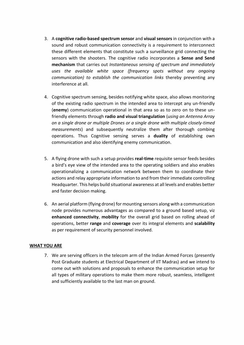
3. A cognitive radio-based spectrum sensor and visual sensors in conjunction with a
sound and robust communication connectivity is a requirement to interconnect
these different elements that constitute such a surveillance grid connecting the
sensors with the shooters. The cognitive radio incorporates a Sense and Send
mechanism that carries out Instantaneous sensing of spectrum and immediately
uses the available white space (frequency spots without any ongoing
communication) to establish the communication links thereby preventing any
interference at all.
4. Cognitive spectrum sensing, besides notifying white space, also allows monitoring
of the existing radio spectrum in the intended area to intercept any un-friendly
(enemy) communication operational in that area so as to zero on to these un-
friendly elements through radio and visual triangulation (using an Antenna Array
on a single drone or multiple Drones or a single drone with multiple closely-timed
measurements) and subsequently neutralize them after thorough combing
operations. Thus Cognitive sensing serves a duality of establishing own
communication and also identifying enemy communication.
5. A flying drone with such a setup provides real-time requisite sensor feeds besides
a bird’s eye view of the intended area to the operating soldiers and also enables
operationalizing a communication network between them to coordinate their
actions and relay appropriate information to and from their immediate controlling
Headquarter. This helps build situational awareness at all levels and enables better
and faster decision making.
6. An aerial platform (flying drone) for mounting sensors along with a communication
node provides numerous advantages as compared to a ground based setup, viz
enhanced connectivity, mobility for the overall grid based on rolling ahead of
operations, better range and coverage over its integral elements and scalability
as per requirement of security personnel involved.
WHAT YOU ARE
7. We are serving officers in the telecom arm of the Indian Armed Forces (presently
Post Graduate students at Electrical Department of IIT Madras) and we intend to
come out with solutions and proposals to enhance the communication setup for
all types of military operations to make them more robust, seamless, intelligent
and sufficiently available to the last man on ground.

PLAN OF ACTION
8. An area of operation is chosen based on tactical interest and the drone is made
airborne over that area from a nearby vantage point. This mobile aerial platform
is mounted with cognitive spectrum-scanning Sensor (based on “SweepSense”1
technology that allows low cost, rapid Wide Band scanning of desired spectrum) ,
Night Vision capable HD cameras and other allied sensors (IR- Infra Red, Motion ,
Chemical based etc) that detects enemy signature and passes on this live
information along with coordinates to the patrolling team which starts zeroing on
to this area to neutralize and sanitize the developing threat.
9. “SweepSense” is a new cognitive spectrum sensing technology which is capable of
carrying out low-cost, quick scanning of the wide spectrum to capture any burst of
communication anywhere on it. It scans 5 GHz wide spectrum in about 5
milliseconds and takes nearly 200 RF spectrum “snapshots” per second allowing it
to detect any use of spectrum in this wide range. It is currently the fastest scanning
rate among all known methods. It can detect presence of a frequency hopped radio
also.
10. The enemy signature comprises the following:-
(a) Detection of un-friendly communication on specific frequency spots as a result
of comprehensive Wide Band radio scanning by Spectrum sensor gives out
information about presence of elements other than own forces in the vicinity.
(b) On-board Radio triangulation enables estimation of general direction and area
of presence of enemy elements for the ground troops to pursue and zero on.
(c) Visual feed provides real time bird’s eye view of the intended area of action
and help builds up situational awareness as the operation progresses.
(d) Additional sensors like IR (Infra-Red), Motion etc will add value to the overall
picture for the ground troops and the commander.
11. As the patrolling party moves on ground they connect on to the communication
cloud, created on white space, by the drone and this provides inter-connectivity
between all patrolling soldiers allowing them to coordinate their move and
execute their plan besides access to the direct feed from the available mounted
sensors on their handsets for updated situational awareness.
12. This communication network also allows the patrolling party leader to connect up
and share information with their controlling Headquarter for further orders on the
operation. The backhaul relay link can be established through a satellite link-up
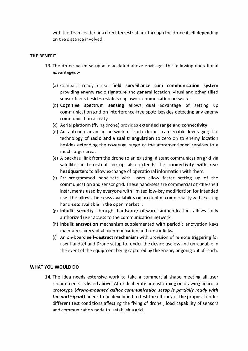
with the Team leader or a direct terrestrial-link through the drone itself depending
on the distance involved.
THE BENEFIT
13. The drone-based setup as elucidated above envisages the following operational
advantages :-
(a) Compact ready-to-use field surveillance cum communication system
providing enemy radio signature and general location, visual and other allied
sensor feeds besides establishing own communication network.
(b) Cognitive spectrum sensing allows dual advantage of setting up
communication grid on interference-free spots besides detecting any enemy
communication activity.
(c) Aerial platform (flying drone) provides extended range and connectivity.
(d) An antenna array or network of such drones can enable leveraging the
technology of radio and visual triangulation to zero on to enemy location
besides extending the coverage range of the aforementioned services to a
much larger area.
(e) A backhaul link from the drone to an existing, distant communication grid via
satellite or terrestrial link-up also extends the connectivity with rear
headquarters to allow exchange of operational information with them.
(f) Pre-programmed hand-sets with users allow faster setting up of the
communication and sensor grid. These hand-sets are commercial off-the-shelf
instruments used by everyone with limited low-key modification for intended
use. This allows their easy availability on account of commonality with existing
hand-sets available in the open market. .
(g) Inbuilt security through hardware/software authentication allows only
authorized user access to the communication network.
(h) Inbuilt encryption mechanism supplemented with periodic encryption keys
maintain secrecy of all communication and sensor links.
(i) An on-board self-destruct mechanism with provision of remote triggering for
user handset and Drone setup to render the device useless and unreadable in
the event of the equipment being captured by the enemy or going out of reach.
WHAT YOU WOULD DO
14. The idea needs extensive work to take a commercial shape meeting all user
requirements as listed above. After deliberate brainstorming on drawing board, a
prototype (drone-mounted adhoc communication setup is partially ready with
the participant) needs to be developed to test the efficacy of the proposal under
different test conditions affecting the flying of drone , load capability of sensors
and communication node to establish a grid.
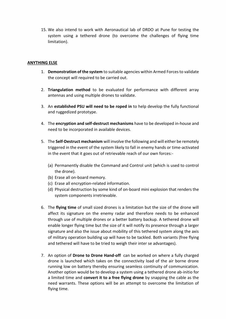
15. We also intend to work with Aeronautical lab of DRDO at Pune for testing the
system using a tethered drone (to overcome the challenges of flying time
limitation).
ANYTHING ELSE
1. Demonstration of the system to suitable agencies within Armed Forces to validate
the concept will required to be carried out.
2. Triangulation method to be evaluated for performance with different array antennas and using multiple drones to validate.
3. An established PSU will need to be roped in to help develop the fully functional
and ruggedized prototype.
4. The encryption and self-destruct mechanisms have to be developed in-house and
need to be incorporated in available devices.
5. The Self-Destruct mechanism will involve the following and will either be remotely
triggered in the event of the system likely to fall in enemy hands or time-activated
in the event that it goes out of retrievable reach of our own forces:-
(a) Permanently disable the Command and Control unit (which is used to control
the drone).
(b) Erase all on-board memory.
(c) Erase all encryption-related information.
(d) Physical destruction by some kind of on-board mini explosion that renders the
system components irretrievable.
6. The flying time of small sized drones is a limitation but the size of the drone will
affect its signature on the enemy radar and therefore needs to be enhanced
through use of multiple drones or a better battery backup. A tethered drone will
enable longer flying time but the size of it will notify its presence through a larger
signature and also the issue about mobility of this tethered system along the axis
of military operation building up will have to be tackled. Both variants (free flying
and tethered will have to be tried to weigh their inter se advantages).
7. An option of Drone to Drone Hand-off can be worked on where a fully charged drone is launched which takes on the connectivity load of the air borne drone running low on battery thereby ensuring seamless continuity of communication. Another option would be to develop a system using a tethered drone ab-initio for a limited time and convert it to a free flying drone by snapping the cable as the need warrants. These options will be an attempt to overcome the limitation of flying time.

8. This very system, without military-specific modifications of encryption and
secrecy, has strong application for PPDR (Personnel Protection and Disaster Relief) services to establish own spread out communication grid to coordinate their operations in the wake of a natural disaster when existing terrestrial communication breaks down. This robust grid can be life-critical in their rescue work.
REFERENCES
1. “SweepSense : Sensing 5 GHz in 5 Milliseconds with Low-Cost Radios” by
Yeswanth Guddeti , Raghav Subbaraman†, Moein Khazraee , Aaron Schulman,
and Dinesh Bharadia
UC San Diego †IIT Madras


APPENDIX E
COMPARISON BETWEEN FIXED WING DRONE
AND ROTARY QUADCOPTER

COMPARISON BETWEEN FIXED WING DRONE AND ROTARY QUADCOPTER
SNo Comparision Parameter Remarks
1. HoveringBy staying put in the air (means hovering),a quadcopter allows to take photographs or keep an electric eye out for trouble.
A quadcopter is better in this regard.
2. Take-OffQuadcopters have an advantage over fixed-wing drones in that there’s no wind-up to the pitch. Even small fixed-wing drones need, if not a runway, to be thrown by hand. And once in the air, if you want to inspect, say, a construction site or telephone pole, it’s easier for a quadcopter to shoot upward.Fixed wing aircraft require a larger take off and landing zone for flight.This can also lead to more time required for setup, takeoff, and landing.
A quadcopter is better in this regard.
3. Greater ManeuverabilityQuadcopter can perform vertical takeoffs and landings. They also require less space to take flight, can hover mid-flight, and maneuver up and around objects for easy inspection, mapping, and modeling. This makes them ideal for area mapping due to the number of flight legs often required to get sufficient overlap to make high quality maps.Fixed wing aircraft are not as well suited for area mapping. This is because many turns are needed to fly a grid pattern and get sufficient overlap of a target area. Fixed wing vehicles require larger area for turning, and do not possess the maneuverability of a quadcopter.
A quadcopter is better in this regard.
4. More CompactQuadcopters vehicles don’t require the surface area or wingspan that fixed wing aircraft do because they use multiple propellers to maneuver. They are designed to fold down and pack up into smaller cases ,making them easier to transport. Even the larger hexacopters and octocopters fold down to a portable size.
A quadcopter is better in this regard.
5. Ease of UseMulti-rotor aircraft are easier to fly for both humans and autopilots.Quick to maneuver, and capable of making movements in any direction, copters have a shorter learning curve for beginners taking flight for the first time.Fixed wing aircraft are harder to fly, both for humans and autopilots, especially in an evolving sense-and-avoid landscape.
A quadcopter is better in this regard.
6. PayloadTo transport something over long distances quickly, fixed-wing drones are more efficient where in they consumes less fuel for more speed.Quadcopters generally support more weight due to their design,however,it will then need a larger drone which would entail more expensive drone.
Depands on the requirement.
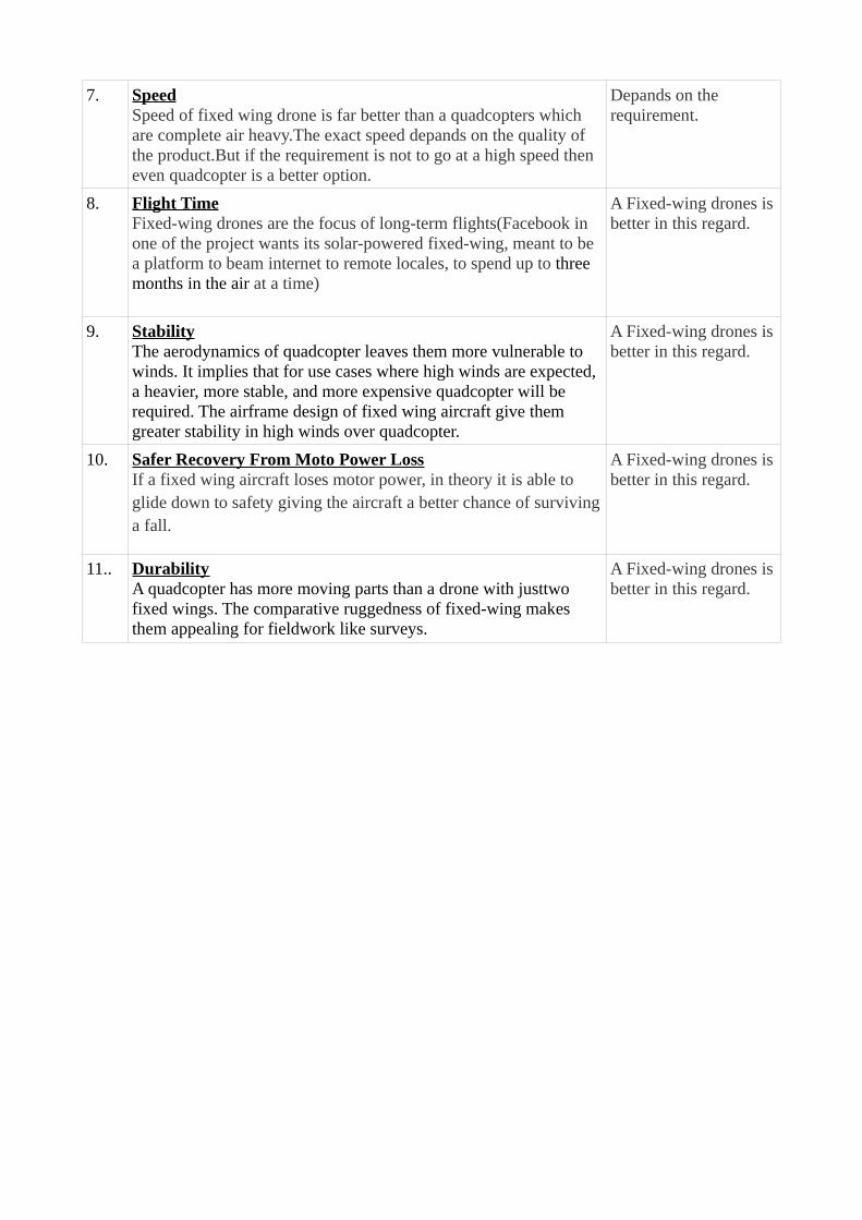
7. SpeedSpeed of fixed wing drone is far better than a quadcopters which are complete air heavy.The exact speed depands on the quality of the product.But if the requirement is not to go at a high speed then even quadcopter is a better option.
Depands on the requirement.
8. Flight TimeFixed-wing drones are the focus of long-term flights(Facebook in one of the project wants its solar-powered fixed-wing, meant to be a platform to beam internet to remote locales, to spend up to three months in the air at a time)
A Fixed-wing drones isbetter in this regard.
9. StabilityThe aerodynamics of quadcopter leaves them more vulnerable to winds. It implies that for use cases where high winds are expected, a heavier, more stable, and more expensive quadcopter will be required. The airframe design of fixed wing aircraft give them greater stability in high winds over quadcopter.
A Fixed-wing drones isbetter in this regard.
10. Safer Recovery From Moto Power LossIf a fixed wing aircraft loses motor power, in theory it is able to glide down to safety giving the aircraft a better chance of survivinga fall.
A Fixed-wing drones isbetter in this regard.
11.. DurabilityA quadcopter has more moving parts than a drone with justtwo fixed wings. The comparative ruggedness of fixed-wing makes them appealing for fieldwork like surveys.
A Fixed-wing drones isbetter in this regard.

.
64
LIST OF REFRENCES
1. Yong Zeng, Rui Zeng, and Teng Joon Lim ( National University of Singapore) Wireless Communication with Unmanned Aerial Vehciles: Opportuinitiesand Challenges IEEE Communication Magzine. 18 May 2016, Page 36-42
2. Technical requirements for Mission Critical Broadband PPDR Communica-tionsAPT report Document, AWG15/OUT-09 dt 29 Aug 2013.
3. Next Generation PPDR Communication Networks TRAI Consultation dated09 Oct 2017.
4. Next Generation PPDR Communication Networks TRAI Recommendationsdated 04 Jun 2018.
5. K. Guevara, M. Rodriguez, N. Gallo, G. Velasco, K. Vasudev, and I. Guvenc ( De-partment of Electical and Computer Engineering, Flourida International Univer-sity, Maimi, 10555 W Flagler Street,USA )UAV-Based GSM Network for Pub-lic Safety Communications IEEE SoutheastCon,Fort Lauderdale,Flourida,Apr9-12, 2015.
6. Yeswanth Guddeti, Raghav Subbaraman (IIT Madras), Moein Aaron Schulmanand Dinesh Bharadia (UC San Diego)SweepSense : Sensing 5 GHz in 5 Milisec-onds with Low-Cost Radios 16th USENIX Symposium on Networked SystemsDesign and Implementation (NSDI ’19). February 26–28, 2019, Boston, MA,USA.
7. Stephen J. Shellhammer ( Qualcomm Inc.5775 Morehouse Drive San Diego, CA92121 )Spectrum Sensing In IEEE 802.22 28 Jul 2010.
8. Péter Hell, Miklós Mezei and Péter János Varga Kandó Kálmán (Faculty of Elec-trical Engineering, Óbuda University, Budapest, Hungary) Drone communica-tions analysis IEEE 15th International Symposium on Applied Machine Intelli-gence and Informatics, January 26-28, 2017, Herl’any, Slovakia
9. Syed Ahsan Raza Naqvi, Syed Ali Hassan, Haris Pervaiz, and Qiang Ni Drone-Aided Communication as a Key Enabler for 5G and Resilient Public SafetyNetworks IEEE Communications Magazine, Volume 56, Issue 1, dt 12 Jan 2018,Page 36-42
10. Satoshi Fujii, Kohei Hiranaka, Seichio Miyagi, Motoki Kyan,Shouichi Tanifuji,Tansuriyavong Suriyon, Zacharie Mbaitiga. Noriaki Yoshikawa, Kensaku Ki-noshita. Integration of drones’ communication into an ITSnetwork ICIIBMS2017, Track1: Signal Processing, Computer Networks and Telecommunications,Okinawa, Japan..
65