a-dec 541 and 545 delivery system mount on preference ... 541 installation guide.pdf · a-dec 541...
TRANSCRIPT

A-dec 541 and 545 Delivery System Mount on Preference Collection 5580I N S T A L L A T I O N G U I D E
86.0003.00 Rev E
Introduction
This document contains instructions for installing a 541/545 delivery system mount on a Preference Collection 5580 cabinet subbase. These instructions are intended for instances where the delivery system mount cannot be attached directly to the floor.
This guide contains the following sections:
• Recommended tools
• Things to do before you begin
• Installation steps
○ Installation with factory installed mounting hardware (page 4)
○ Retrofit installation without factory installed mounting hardware (page 5)
Recommended Tools
• Hex key set
• Torque wrench
NOTE To mount a 541/545 system on a Preference Collection 5580 not containing subbase cutouts (see Figure 3), order a new style subbase front and qty (8) 012-004-00 pop rivets. Affected Preference Collection 5580 cabinets are those shipped before October 3, 2005.
Figure 1. A-dec 500 Cabinet-Mounted 541/545 Delivery System

A-dec 541 and 545 Delivery System Mount on Preference Collection 5580 Installation Guide
2 86.0003.00 Rev E
Before You Begin
1. Check with local building and code authorities about installation requirements. These differ from state to state and internationally.
2. Check that the manual air shut-off valve is installed.
3. Install the 5580 cabinet. Refer to the Preference Collection 5580.69 and 5580.96 Treatment Console Installation Guide (P/N 86.0199.00).
4. Locate all parts, tools, and hardware for this installation.
5. Some older cabinets may need new mounting holes drilled in the bottom panel for the four decorative screws that secure the upper support bracket assemblies. If necessary, drill these additional holes before beginning the installation. Holes should be 3/8" (9.5 mm) in diameter and 2" (51 mm) from the edges of the panel. See Figure 2 for the mounting hole locations on an older-style bottom panel. (Figure 3 on the next page shows the newer-style bottom panel.)
CAUTION The 5580 subbase must be anchored to the floor to prevent tipping or injury. Refer to Anchoring the Preference Collection Sub-Base Installation Guide (P/N 86.0159.00) for anchoring instructions.
WARNING Failure to anchor the cabinet to the floor can lead to product damage and result in serious injury or death.
Figure 2. Drill New Mounting Holes (If Necessary)
(A) Current Hole and Decorative Screws; (B) Drilling Locations for New Holes
Bottom Panel
B
A
Cabinet Wall

A-dec 541 and 545 Delivery System Mount on Preference Collection 5580 Installation Guide
86.0003.00 Rev E 3
Parts Identification
Refer to Figure 3 to identify parts used in the installation of the 541/545 mount. Parts are shown exploded for clarity.
Figure 3. Detail of the 541/545 Mount on a 5580 Cabinet Sub-Base
A
B
C
H
E
F
J
D
G
L
M
Subbase Cutouts
(A) (4) Decorative Screws; (B) Bottom Panel; (C) Upper Rail; (D) Upper Support Bracket; (E) Subbase; (F) Subbase Front; (G) (4) Socket Head Screws; (H) Anchor Plate; (J) Clips; (K) (10) 1/4-20 x 3/8" Socket Head Patch Screws; (L) Adjustment Brackets; (M) 541/545 Mount; (N) Washers
K
N

A-dec 541 and 545 Delivery System Mount on Preference Collection 5580 Installation Guide
4 86.0003.00 Rev E
Installation Steps
Proceed to the installation steps for the type of installation:
• 5580 cabinets with the 541/545 mounting option factory installed. See Cabinets with Factory-Installed Mounting Hardware below.
• 5580 cabinets without the 541/545 mounting option pre-installed See Cabinets Without Factory-Installed Mounting Hardware on page 5.
Cabinets with Factory-Installed Mounting Hardware
1. Loosen the six (1/4-20 x 3/8" socket head patch) adjustment bracket screws. See Figure 4. This allows the adjustment brackets to slide up as needed when the 541/545 mount is inserted under the cabinet.
2. Slide the 541/545 mount under the cabinet. See Figure 4.
3. Partially tighten the six (1/4-20 x 3/8" socket head patch) adjustment bracket screws.
4. Position the anchor plate on the two adjustment brackets. See Figure 5.
5. Secure the anchor plate using four socket head patch screws and washers included in the kit.
Only partially tighten the screws to allow the 541/545 floor mount to move freely while positioning so that good contact with the floor can be made.
6. Check that the 541/545 mount is flush with the floor.
Figure 4. Loosen the Adjustment Bracket Screws
(A) Socket Head Patch Screws; (B) Adjustment Brackets; (C) 541/545 Mount
Figure 5. Position the Anchor Plate on the Adjustment Brackets
(A) Anchor Plate; (B) Adjustment Brackets
A
B
C
B
A
B
B

A-dec 541 and 545 Delivery System Mount on Preference Collection 5580 Installation Guide
86.0003.00 Rev E 5
7. Tighten the 541/545 mount screws to 15 ft lb. See Figure 6.
8. Verify that the 541/545 mount did not lift up when the anchor plate was installed. The mount should still be flush with the floor.
9. Completely tighten the six 1/4-20 x 3/8" socket head patch screws on the adjustment brackets. See Figure 3.
Install the 541/545 Delivery System
Follow the steps in the A-dec 500 12 O’Clock System Installation Guide (P/N 86.0466.00) to install the 541/545 delivery system.
Test the System
When installation is complete, recheck that the 541/545 mount is flush with the floor and that all screws are fully tightened.
Cabinets Without Factory-Installed Mounting Hardware
Remove the Subbase Clips
1. Loosen the decorative screws securing the subbase clips to the cabinet’s bottom panel. See Figure 7.
2. Remove and discard the clips.
3. Leave the screws in the panel for mounting the upper support bracket assemblies.
Figure 6. Attach the Anchor Plate and 541/545 Mount
(A) 541/545 Mount Screws; (B) Anchor Plate; (C) 541/545 Mount; (D) Adjustment Brackets; (E) Socket Head Patch Screws; (F) Washers
Figure 7. Remove the Subbase Clips
B
A
CD
E
F
Decorative Screw
Clip
A-dec 541 and 545 Delivery System Mount on Preference Collection 5580 Installation Guide
6 86.0003.00 Rev E
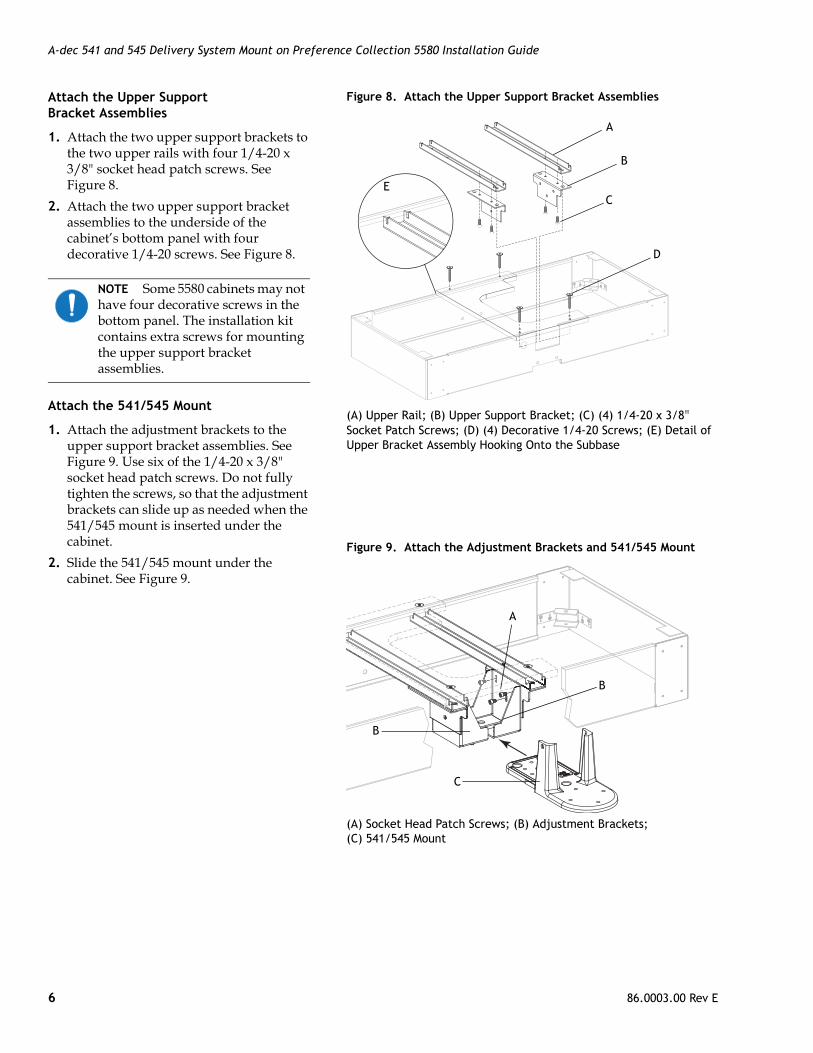
Attach the Upper Support Bracket Assemblies
1. Attach the two upper support brackets to the two upper rails with four 1/4-20 x 3/8" socket head patch screws. See Figure 8.
2. Attach the two upper support bracket assemblies to the underside of the cabinet’s bottom panel with four decorative 1/4-20 screws. See Figure 8.
Attach the 541/545 Mount
1. Attach the adjustment brackets to the upper support bracket assemblies. See Figure 9. Use six of the 1/4-20 x 3/8" socket head patch screws. Do not fully tighten the screws, so that the adjustment brackets can slide up as needed when the 541/545 mount is inserted under the cabinet.
2. Slide the 541/545 mount under the cabinet. See Figure 9.
NOTE Some 5580 cabinets may not have four decorative screws in the bottom panel. The installation kit contains extra screws for mounting the upper support bracket assemblies.
Figure 8. Attach the Upper Support Bracket Assemblies
(A) Upper Rail; (B) Upper Support Bracket; (C) (4) 1/4-20 x 3/8" Socket Patch Screws; (D) (4) Decorative 1/4-20 Screws; (E) Detail of Upper Bracket Assembly Hooking Onto the Subbase
Figure 9. Attach the Adjustment Brackets and 541/545 Mount
(A) Socket Head Patch Screws; (B) Adjustment Brackets; (C) 541/545 Mount
A
E
B
C
D
A
B
C
B

A-dec 541 and 545 Delivery System Mount on Preference Collection 5580 Installation Guide
86.0003.00 Rev E 7
3. Position the anchor plate on the two adjustment brackets. See Figure 10.
4. Secure the anchor plate using four socket head patch screws included in kit.
Only partially tighten the screws to allow the 541/545 floor mount to move freely while positioning so good contact with the floor can be made.
5. Check that the 541/545 mount is flush with the floor.
6. Tighten the 541/545 mount screws to secure the mount. Torque the screws to 15 ft lb.
7. Verify that the 541/545 mount did not lift up when the anchor plate was installed. The mount should still be flush with the floor.
8. Completely tighten the six socket head patch screws on the adjustment brackets. See Figure 11.
Install the 541/545 Delivery System
Follow the steps in the A-dec 500 12 O’Clock System Installation Guide (P/N 86.0466.00) to install the 541/545 delivery system.
Test the System
When installation is complete, recheck that the 541/545 mount is flush with the floor and that all screws are fully tightened.
Figure 10. Position the Anchor Plate on the Adjustment Brackets
(A) Anchor Plate; (B) Adjustment Brackets
Figure 11. Attach the Anchor Plate and the 541/545 Mount
(A) 541/545 Mount Screws; (B) Anchor Plate; (C) 541/545 Mount; (D) Adjustment Brackets; (E) Socket Head Patch Screws; (F) Washers
A
B
B
B
A
CD
E
F

A-dec 541 and 545 Delivery System Mount on Preference Collection 5580 Installation Guide
A-dec Headquarters2601 Crestview DriveNewberg, OR 97132 USATel:1.800.547.1883 Within USA/CanadaTel:1.503.538.7478 Outside USA/CanadaFax:1.503.538.0276
www.a-dec.com / www.a-dec.biz
A-dec Inc. makes no warranty of any kind with regard to the content in this document including, but not limited to, the implied warranties of merchantability and fitness for a particular purpose.
ÍvÈ.ÇÂ#È.00&Î86.0003.00 Rev E
Copyright 2013 A-dec Inc.All rights reserved.
IGgrphpor4
Regulatory Information
Regulatory information is provided with A-dec equipment as mandated by agency requirements. This information is delivered in the equipment’s Instructions for Use or the separate Regulatory Information and Specifications document. If you need this information, please go to the Document Library at www.a-dec.com.