a-96.250.811 / 270721 operator’s manual - swan
TRANSCRIPT

Operator’s ManualFirmware V6.31 and higher
AMI Silitrace
A-96.250.811 / 270721
© 2017, Swan Analytische Instrumente AG, Switzerland, all rights reserved.
The information contained in this document is subject to change without notice.
Customer SupportSwan and its representatives maintain a fully trained staff of technical specialists around the world. For any technical question, contact your nearest Swan representative, or the manufacturer:
Swan Analytische Instrumente AGStudbachstrasse 138340 HinwilSwitzerland
Internet: www.swan.chE-mail: [email protected]
Document Status
Title: AMI Silitrace Operator’s Manual
ID: A-96.250.811
Revision Issue
00 Oct. 2015 First Edition
01 Aug. 2016 Update to FW Release 6.20, Mainboard Rev. 2.5
02 Mar. 2017 Update to FW Release 6.30 (adds multi-channel capability)
A-96.250.811 / 270721
AMI Silitrace
3
Table of Contents
1. Safety Instructions . . . . . . . . . . . . . . . . . . . . . . . . . . . . . . . . . . . . . . . . . . . . . 61.1. Warning Notices . . . . . . . . . . . . . . . . . . . . . . . . . . . . . . . . . . . . . . . . . . . . . . . . 71.2. General Safety Regulations . . . . . . . . . . . . . . . . . . . . . . . . . . . . . . . . . . . . . . . 92. Product Description . . . . . . . . . . . . . . . . . . . . . . . . . . . . . . . . . . . . . . . . . . . . 102.1. Description of the System . . . . . . . . . . . . . . . . . . . . . . . . . . . . . . . . . . . . . . . . . 102.2. Instrument Specification . . . . . . . . . . . . . . . . . . . . . . . . . . . . . . . . . . . . . . . . . . 142.3. Instrument Overview . . . . . . . . . . . . . . . . . . . . . . . . . . . . . . . . . . . . . . . . . . . . . 163. Installation . . . . . . . . . . . . . . . . . . . . . . . . . . . . . . . . . . . . . . . . . . . . . . . . . . . . 173.1. Installation Checklist . . . . . . . . . . . . . . . . . . . . . . . . . . . . . . . . . . . . . . . . . . . . . 173.2. Mounting the Instrument Panel . . . . . . . . . . . . . . . . . . . . . . . . . . . . . . . . . . . . . 183.3. Connecting Sample and Waste. . . . . . . . . . . . . . . . . . . . . . . . . . . . . . . . . . . . . 193.3.1 AMI Silitrace. . . . . . . . . . . . . . . . . . . . . . . . . . . . . . . . . . . . . . . . . . . . . . . . . . 193.3.2 AMI Silitrace Dual-Stream . . . . . . . . . . . . . . . . . . . . . . . . . . . . . . . . . . . . . . . 203.4. Degassing Membrane (Option) . . . . . . . . . . . . . . . . . . . . . . . . . . . . . . . . . . . . . 213.4.1 Contents of the Installation Kit . . . . . . . . . . . . . . . . . . . . . . . . . . . . . . . . . . . . 213.4.2 Additionally Required Items . . . . . . . . . . . . . . . . . . . . . . . . . . . . . . . . . . . . . . 213.4.3 Installation . . . . . . . . . . . . . . . . . . . . . . . . . . . . . . . . . . . . . . . . . . . . . . . . . . . 223.5. Electrical Connections. . . . . . . . . . . . . . . . . . . . . . . . . . . . . . . . . . . . . . . . . . . . 243.5.1 Connection Diagram . . . . . . . . . . . . . . . . . . . . . . . . . . . . . . . . . . . . . . . . . . . 263.5.2 Power Supply. . . . . . . . . . . . . . . . . . . . . . . . . . . . . . . . . . . . . . . . . . . . . . . . . 273.6. Relay Contacts . . . . . . . . . . . . . . . . . . . . . . . . . . . . . . . . . . . . . . . . . . . . . . . . . 283.6.1 Input . . . . . . . . . . . . . . . . . . . . . . . . . . . . . . . . . . . . . . . . . . . . . . . . . . . . . . . . 283.6.2 Alarm Relay . . . . . . . . . . . . . . . . . . . . . . . . . . . . . . . . . . . . . . . . . . . . . . . . . . 283.6.3 Relay 1 and 2. . . . . . . . . . . . . . . . . . . . . . . . . . . . . . . . . . . . . . . . . . . . . . . . . 293.7. Signal Outputs. . . . . . . . . . . . . . . . . . . . . . . . . . . . . . . . . . . . . . . . . . . . . . . . . . 313.7.1 Signal Output 1 and 2 (current outputs). . . . . . . . . . . . . . . . . . . . . . . . . . . . . 313.8. Interface Options . . . . . . . . . . . . . . . . . . . . . . . . . . . . . . . . . . . . . . . . . . . . . . . . 313.8.1 Signal Output 3 . . . . . . . . . . . . . . . . . . . . . . . . . . . . . . . . . . . . . . . . . . . . . . . 323.8.2 Profibus, Modbus Interface . . . . . . . . . . . . . . . . . . . . . . . . . . . . . . . . . . . . . . 323.8.3 HART Interface . . . . . . . . . . . . . . . . . . . . . . . . . . . . . . . . . . . . . . . . . . . . . . . 333.8.4 USB Interface. . . . . . . . . . . . . . . . . . . . . . . . . . . . . . . . . . . . . . . . . . . . . . . . . 33

A-96.250.811 / 270721
AMI Silitrace
4
4. Instrument Setup . . . . . . . . . . . . . . . . . . . . . . . . . . . . . . . . . . . . . . . . . . . . . . . 344.1. Start-up Procedure. . . . . . . . . . . . . . . . . . . . . . . . . . . . . . . . . . . . . . . . . . . . . . . 344.2 Prepare Reagents . . . . . . . . . . . . . . . . . . . . . . . . . . . . . . . . . . . . . . . . . . . . . . . 364.3. Prepare Standard. . . . . . . . . . . . . . . . . . . . . . . . . . . . . . . . . . . . . . . . . . . . . . . . 364.4. Switch on Power . . . . . . . . . . . . . . . . . . . . . . . . . . . . . . . . . . . . . . . . . . . . . . . . 384.5. Adjust Sample Flow . . . . . . . . . . . . . . . . . . . . . . . . . . . . . . . . . . . . . . . . . . . . . . 384.6. Activate the Peristaltic pump . . . . . . . . . . . . . . . . . . . . . . . . . . . . . . . . . . . . . . . 404.7. Programming . . . . . . . . . . . . . . . . . . . . . . . . . . . . . . . . . . . . . . . . . . . . . . . . . . . 414.7.1 AMI Sample Sequencer (Option) . . . . . . . . . . . . . . . . . . . . . . . . . . . . . . . . . . 414.8. Final Tests . . . . . . . . . . . . . . . . . . . . . . . . . . . . . . . . . . . . . . . . . . . . . . . . . . . . . 425. Operation . . . . . . . . . . . . . . . . . . . . . . . . . . . . . . . . . . . . . . . . . . . . . . . . . . . . . 455.1. Keys . . . . . . . . . . . . . . . . . . . . . . . . . . . . . . . . . . . . . . . . . . . . . . . . . . . . . . . . . . 455.2. Display . . . . . . . . . . . . . . . . . . . . . . . . . . . . . . . . . . . . . . . . . . . . . . . . . . . . . . . . 465.3. Software Structure . . . . . . . . . . . . . . . . . . . . . . . . . . . . . . . . . . . . . . . . . . . . . . . 485.4. Changing Parameters and values . . . . . . . . . . . . . . . . . . . . . . . . . . . . . . . . . . . 495.5. Grab Sample Measurement . . . . . . . . . . . . . . . . . . . . . . . . . . . . . . . . . . . . . . . . 506. Maintenance . . . . . . . . . . . . . . . . . . . . . . . . . . . . . . . . . . . . . . . . . . . . . . . . . . . 526.1. Maintenance Table. . . . . . . . . . . . . . . . . . . . . . . . . . . . . . . . . . . . . . . . . . . . . . . 526.2. Stop of Operation for Maintenance . . . . . . . . . . . . . . . . . . . . . . . . . . . . . . . . . . 526.3. Refill or Replace Reagents . . . . . . . . . . . . . . . . . . . . . . . . . . . . . . . . . . . . . . . . 536.4. Calibration . . . . . . . . . . . . . . . . . . . . . . . . . . . . . . . . . . . . . . . . . . . . . . . . . . . . . 566.5. Verification . . . . . . . . . . . . . . . . . . . . . . . . . . . . . . . . . . . . . . . . . . . . . . . . . . . . . 576.6. Zero . . . . . . . . . . . . . . . . . . . . . . . . . . . . . . . . . . . . . . . . . . . . . . . . . . . . . . . . . . 586.7. Replace the Pump Tubes. . . . . . . . . . . . . . . . . . . . . . . . . . . . . . . . . . . . . . . . . . 596.8. Fill System . . . . . . . . . . . . . . . . . . . . . . . . . . . . . . . . . . . . . . . . . . . . . . . . . . . . . 616.9. Clean the Photometer . . . . . . . . . . . . . . . . . . . . . . . . . . . . . . . . . . . . . . . . . . . . 626.10. Longer Stop of Operation. . . . . . . . . . . . . . . . . . . . . . . . . . . . . . . . . . . . . . . . . . 627. Troubleshooting. . . . . . . . . . . . . . . . . . . . . . . . . . . . . . . . . . . . . . . . . . . . . . . . 637.1. Error List. . . . . . . . . . . . . . . . . . . . . . . . . . . . . . . . . . . . . . . . . . . . . . . . . . . . . . . 637.2. Replace the reaction chamber . . . . . . . . . . . . . . . . . . . . . . . . . . . . . . . . . . . . . . 687.3. Replace the 6-Way Valve. . . . . . . . . . . . . . . . . . . . . . . . . . . . . . . . . . . . . . . . . . 707.4. Replace the Cuvette. . . . . . . . . . . . . . . . . . . . . . . . . . . . . . . . . . . . . . . . . . . . . . 727.5. Replace the Reagent Tubes . . . . . . . . . . . . . . . . . . . . . . . . . . . . . . . . . . . . . . . 737.6. Cleaning the solenoid valve . . . . . . . . . . . . . . . . . . . . . . . . . . . . . . . . . . . . . . . . 757.7. Opening the peristaltic pump housing . . . . . . . . . . . . . . . . . . . . . . . . . . . . . . . . 777.8. Replacing Fuses . . . . . . . . . . . . . . . . . . . . . . . . . . . . . . . . . . . . . . . . . . . . . . . . 78

A-96.250.811 / 270721
AMI Silitrace
5
8. Program Overview. . . . . . . . . . . . . . . . . . . . . . . . . . . . . . . . . . . . . . . . . . . . . . 798.1. Messages (Main Menu 1) . . . . . . . . . . . . . . . . . . . . . . . . . . . . . . . . . . . . . . . . . 798.2. Diagnostics (Main Menu 2) . . . . . . . . . . . . . . . . . . . . . . . . . . . . . . . . . . . . . . . . 808.3. Maintenance (Main Menu 3) . . . . . . . . . . . . . . . . . . . . . . . . . . . . . . . . . . . . . . . 818.4. Operation (Main Menu 4) . . . . . . . . . . . . . . . . . . . . . . . . . . . . . . . . . . . . . . . . . 828.5. Installation (Main Menu 5) . . . . . . . . . . . . . . . . . . . . . . . . . . . . . . . . . . . . . . . . . 839. Program List and Explanations . . . . . . . . . . . . . . . . . . . . . . . . . . . . . . . . . . . 85
1 Messages. . . . . . . . . . . . . . . . . . . . . . . . . . . . . . . . . . . . . . . . . . . . . . . . . . . . 852 Diagnostics. . . . . . . . . . . . . . . . . . . . . . . . . . . . . . . . . . . . . . . . . . . . . . . . . . . 853 Maintenance. . . . . . . . . . . . . . . . . . . . . . . . . . . . . . . . . . . . . . . . . . . . . . . . . . 894 Operation . . . . . . . . . . . . . . . . . . . . . . . . . . . . . . . . . . . . . . . . . . . . . . . . . . . . 915 Installation . . . . . . . . . . . . . . . . . . . . . . . . . . . . . . . . . . . . . . . . . . . . . . . . . . . 92
10. Safety Data sheets . . . . . . . . . . . . . . . . . . . . . . . . . . . . . . . . . . . . . . . . . . . . . 10911. Default Values . . . . . . . . . . . . . . . . . . . . . . . . . . . . . . . . . . . . . . . . . . . . . . . . . 11012. Index . . . . . . . . . . . . . . . . . . . . . . . . . . . . . . . . . . . . . . . . . . . . . . . . . . . . . . . . . 11313. Notes . . . . . . . . . . . . . . . . . . . . . . . . . . . . . . . . . . . . . . . . . . . . . . . . . . . . . . . . 115
A-96.250.811 / 270721
AMI SilitraceSafety Instructions
6
Operator’s ManualThis document describes the main steps for instrument setup, operation and maintenance.
1. Safety Instructions
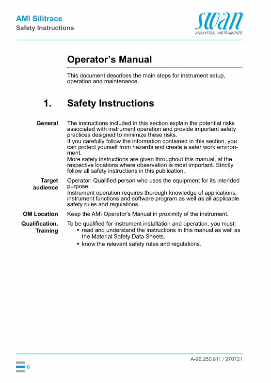
General The instructions included in this section explain the potential risks associated with instrument operation and provide important safety practices designed to minimize these risks.If you carefully follow the information contained in this section, you can protect yourself from hazards and create a safer work environ-ment.More safety instructions are given throughout this manual, at the respective locations where observation is most important. Strictly follow all safety instructions in this publication.
Targetaudience
Operator: Qualified person who uses the equipment for its intended purpose.Instrument operation requires thorough knowledge of applications, instrument functions and software program as well as all applicable safety rules and regulations.
OM Location Keep the AMI Operator’s Manual in proximity of the instrument.Qualification,
TrainingTo be qualified for instrument installation and operation, you must: read and understand the instructions in this manual as well as
the Material Safety Data Sheets. know the relevant safety rules and regulations.

A-96.250.811 / 270721
AMI SilitraceSafety Instructions
7
1.1. Warning NoticesThe symbols used for safety-related notices have the following meaning:
DANGER
Your life or physical wellbeing are in serious danger if such warn-ings are ignored. Follow the prevention instructions carefully.
WARNING
Severe injuries or damage to the equipment can occur if such warnings are ignored. Follow the prevention instructions carefully.
CAUTION
Damage to the equipment, minor injury, malfunctions or incorrect process values can be the consequence if such warnings are ig-nored. Follow the prevention instructions carefully.
MandatorySigns
The mandatory signs in this manual have the following meaning:
Safety goggles
Safety gloves
A-96.250.811 / 270721
AMI SilitraceSafety Instructions
8
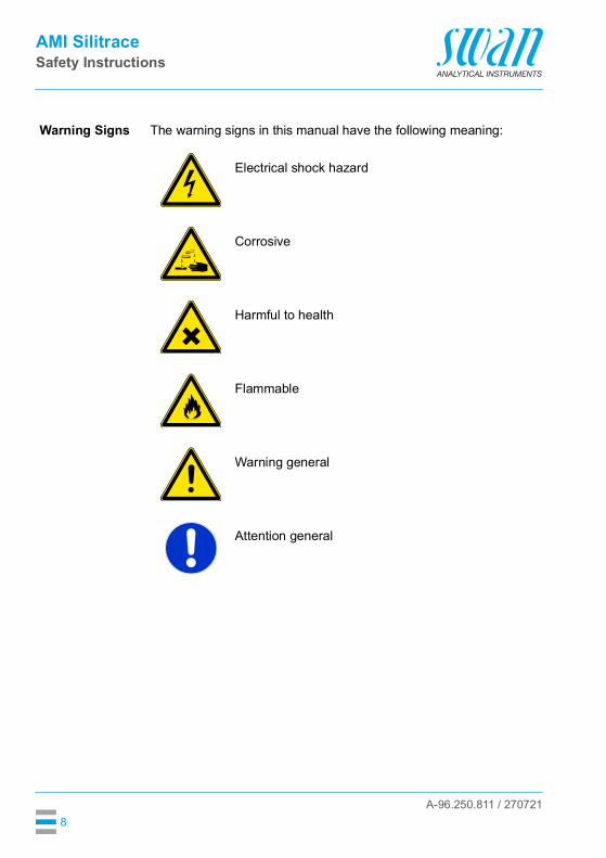
Warning Signs The warning signs in this manual have the following meaning:
Electrical shock hazard
Corrosive
Harmful to health
Flammable
Warning general
Attention general

A-96.250.811 / 270721
AMI SilitraceSafety Instructions
9
1.2. General Safety RegulationsLegal
RequirementsThe user is responsible for proper system operation. All precautions must be followed to ensure safe operation of the instrument.
Spare Partsand
Disposables
Use only official SWAN spare parts and disposables. If other parts are used during the normal warranty period, the manufacturer’s war-ranty is voided.
Modifications Modifications and instrument upgrades shall only be carried out by an authorized Service Technician. SWAN will not accept responsibili-ty for any claim resulting from unauthorized modification or alter-ation.
WARNING
Electrical shock hazardIf proper operation is no longer possible, the instrument must be disconnected from all power lines, and measures must be taken to prevent inadvertent operation. To prevent from electrical shock, always make sure that the
ground wire is connected. Service shall be performed by authorized personnel only. Whenever electronic service is required, disconnect instrument
power and power of devices connected to.– relay 1,– relay 2,– alarm relay
WARNING
For safe instrument installation and operation you must read and understand the instructions in this manual.
WARNING
Only SWAN trained and authorized personnel shall perform the tasks described in this document.

A-96.250.811 / 270721
AMI SilitraceProduct Description
10
2. Product Description
2.1. Description of the SystemApplication
rangeThe AMI Silitrace is a complete monitoring system for the automatic, continuous measurement of the dissolved silica content in water steam cycles or demineralizer plants.
Photometricdetection
of silica
The determination of silica is done by the photometric analysis of molybdate blue at 815 nm.Silica and ortho-phosphates react at low pH with ammonium molyb-date to the yellow colored molybdosilic acid respectively molybdo-phosphoric acid. The molybdophosphoric acid is destroyed with oxalic acid before the molybdosilic acid is reduced with iron-(II)-am-monium-sulfate to the heteropolyblue complex.Especially the reaction speed of the first reaction step to the molyb-dosilic acid is relatively slow. It is the most time consuming part of the whole reaction. As the reaction speed increases with increasing tem-perature, it is time saving to heat up the sample. The AMI Silitrace therefore uses a thermostatic reaction chamber with a constant tem-perature of 45 °C.At 45 °C the complete reaction only needs 150 s (2.5 min). Because the reaction time plays an important role in the color development, the pump speed is adjusted constantly. Due to the automatic heating and reaction time regulation a very high precision is achieved.
Instrumentvariants
The AMI Silitrace is available in two variants: AMI Silitrace AMI Silitrace Dual-Stream
Both instruments are identical except that the AMI Silitrace Dual-Stream includes a channel selector valve.
Degassingmembrane
(option)
Membrane degassing module for the treatment of samples with high gas content or gas-saturated samples. It minimizes bubble formation during heating of the sample in the photometer, which could interfere with the measurement. Requires an external vacuum pump (not in-cluded).
SampleSequencer
If measurement of more than two sample streams is required, the AMI Silitrace can be connected to a Sample Sequencer, which al-lows to measure up to six sample streams.
Automaticcalibration and
verification
A calibration, verification or zero measurement can be performed automatically according to a programmed time schedule or started manually.

A-96.250.811 / 270721
AMI SilitraceProduct Description
11
Grab sample Easy-to-use grab sample function.Signal
OutputsTwo signal outputs programmable for measured values (freely scalable, linear, bilinear, log) or as continuous control output (control parameters programmable).Current loop: 0/4–20 mAMaximal burden: 510 OhmThird signal output available as an option. The third signal output can be operated as a current source or as a current sink (selectable via switch).
Relays Two potential-free contacts programmable as limit switches for mea-suring values, controllers or timer for system cleaning with automatic hold function. Both contacts can be used as normally open or nor-mally closed.Maximum load: 1 A/250 VAC
Alarm Relay One potential free contact.Alternatively: Open during normal operation, closed on error and loss of
power. Closed during normal operation, open on error and loss of
power.Summary alarm indication for programmable alarm values and in-strument faults.
Input One input for potential-free contact to freeze the measuring value or to interrupt control in automated installations (hold function or re-mote-off)
Communica-tion Interface
(optional)
USB Interface for logger download Third signal output (can be used in parallel to the USB interface) RS485 with Fieldbus protocol Modbus or Profibus DP HART interface
SafetyFeatures
No data loss after power failure. All data is saved in non-volatile memory.Over voltage protection of in- and outputs.Galvanic separation of measuring inputs from signal outputs.
A-96.250.811 / 270721
AMI SilitraceProduct Description
12
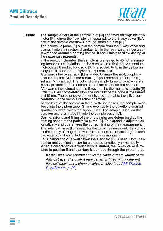
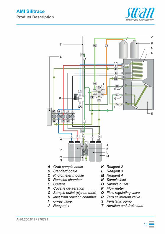
Fluidic The sample enters at the sample inlet [N] and flows through the flow meter [P], where the flow rate is measured, to the 6-way valve [I]. A part of the sample overflows into the sample outlet [O].The peristaltic pump [S] sucks the sample from the 6-way valve and pumps it into the reaction chamber [D]. In the reaction chamber a coil is wrapped around a heating device. It has 4 inlets to allow dosing of the necessary reagents.In the reaction chamber the sample is preheated to 45 °C, eliminat-ing temperature deviations of the sample. In a first step Ammonium-molybdate [J] and sulfuric acid [K] are added, to form the yellowish molybdosilic acid and molybdophosphoric acid.Afterwards the oxalic acid [L] is added to mask the molybdophos-phoric complex. At last the reducing agent ammonium ferrous (II) sulfate [M] is added. The color of the sample turns to blue. As silica is only present in trace amounts, the blue color can not be seen.Afterwards the colored sample flows into the thermostatic cuvette [E] until it is filled completely. Now the intensity of the color is measured at 815 nm. The color development is proportional to the silica con-centration in the sample.reaction chamber.As the level of the sample in the cuvette increases, the sample over-flows into the siphon tube [G] and eventually the cuvette is drained spontaneously through the siphon tube. The sample is led via the aeration and drain tube [T] into the sample outlet [O]. Dosing, mixing and filling of the photometer are determined by the rotating speed of the peristaltic pump [S]. This speed is adjusted au-tomatically and guarantees the correct timing of the measurement.The solenoid valve [R] is used for the zero measurement. It switches off the supply of reagent 1, which is responsible for coloring the sam-ple. A zero can be started automatically or manually.For a calibration or a verification the standard [B] is used. Both, cali-bration and verification can be started automatically or manually. When a calibration or a verification is started, the 6-way valve is ro-tated to position 5 and standard is pumped through the photometer.
Note: The fluidic scheme shows the single-stream variant of the AMI Silitrace. The dual-stream variant is fitted with a different flow cell block and a channel selector valve (see AMI Silitrace Dual-Stream, p. 39).
A-96.250.811 / 270721
AMI SilitraceProduct Description
13
ABCDEFGHIJ
Grab sample bottleStandard bottlePhotometer moduleReaction chamberCuvetteCuvette de-aerationSample outlet (siphon tube)Inlet from reaction chamber6-way valveReagent 1
KLMNOPQRST
Reagent 2Reagent 3Reagent 4Sample inletSample outletFlow meterFlow regulating valveZero calibration valvePeristaltic pumpAeration and drain tube
17
6
54
3
2
12
1
12
05 13
05
1A
1B
1B
2
2
34
1
1A
2
2 3 4
3 4
3 4
04
04
11
11
0102
04
11
12
43
03
04
02
01
03
03
B
A
CD
E
F
G
H
I
JKLM
NO
P
Q
R
S
T

A-96.250.811 / 270721
AMI SilitraceProduct Description
14
2.2. Instrument Specification
Power Supply Voltage:
Power consumption:
100–240 VAC (± 10%)50/60 Hz (± 5%)DC version not availablemax. 50 VA
Transmitterspecifications
Electronics housing
Ambient temperature:Storage and transport:Humidity:Display:
Aluminum with a protection degree of IP 66 / NEMA 4X-10 to +50 °C-30 to +85 °C10–90% rel., non condensingbacklit LCD, 75 x 45 mm
Samplerequirements
Flow rate:Temperature:Inlet pressure:Outlet pressure:
min. 3 l /h5 to 50 °C0.15 to 2 barpressure free
On-site The analyzer site must permit connections to:requirements Sample inlet:
Sample outlet:
Ambient temperature
Serto PVDF 6 mm (1/8”), for tubing 4x6 mmTube 15 x 20 mm(1/2”) hose nozzle which must end in a pressure free waste of sufficient capacity5 to 50 °C
Silicameasurement
Measuring rangeReproducibility:Cycle time:
0.5 to 1’000 ppb± 0.5 ppb or ± 5%, whichever is greater3 min

A-96.250.811 / 270721
AMI SilitraceProduct Description
15
Dimensions Panel:Dimensions:Screws:Weight:
stainless steel400x850x150 mm8 mm16.0 kg
13 m
m /
0.51
"4
x di
a. 1
0 m
m /
0.39
"
850
mm
/ 33
.46"
824
mm
/ 32
.44"
374 mm / 14.72"
400 mm / 15.75"
Exit Enter
AMI Silitrace

A-96.250.811 / 270721
AMI SilitraceProduct Description
16
2.3. Instrument Overview
ABCD
EFGH
PanelStandard bottleGrab sample bottleSolenoid valve for zero calibrationPhotometer module6-way valveFlow regulating valveFlow cell
IJKLMNOPQ
Flow meterSample inletSample outletReagent 4Reagent 3Reagent 2Reagent 1Peristaltic pumpTransmitter
A
BC
D
E
F
I
H
K
L
G
J
N
M
O
P
Q
A-96.250.811 / 270721
AMI SilitraceInstallation
17
3. Installation
3.1. Installation Checklist
On site requirements
100–240 VAC (±10%), 50/60 Hz (±5%)Power consumption: 50 VA maximum.Protective earth connection required.Sample line with sufficient sample flow and pressure (see Instrument Specification, p. 14).
Installation Mounting the Instrument Panel, p. 18.Connecting Sample and Waste, p. 19.
Electrical wiring
Connect all external devices like limit switches, current loops and pumps. Electrical Connections, p. 24.Connect power cord, see Power Supply, p. 27.
Start-up Proceed according to Start-up Procedure, p. 34.
A-96.250.811 / 270721
AMI SilitraceInstallation
18
3.2. Mounting the Instrument PanelThe first part of this chapter describes the preparing and placing of the instrument for use. The instrument must only be installed by trained personnel. Mount the instrument in vertical position. For ease of operation mount it so that the display is at eye
level. For the installation, a kit containing the following installation
material is available:– 4 Screws 8x60 mm– 4 Dowels– 4 Washers 8.4/24 mm
Mountingrequirements
The instrument is only intended for indoor installation. See Dimensions, p. 15.
A-96.250.811 / 270721
AMI SilitraceInstallation
19
3.3. Connecting Sample and Waste
3.3.1 AMI Silitrace
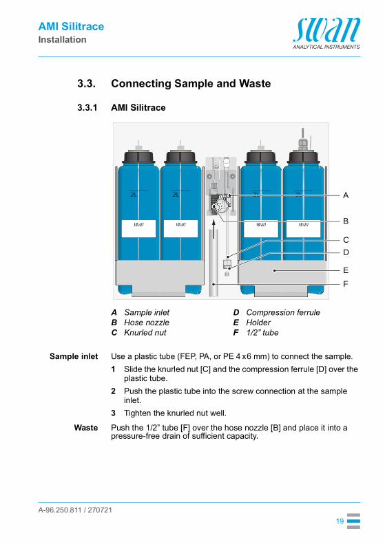
Sample inlet Use a plastic tube (FEP, PA, or PE 4 x6 mm) to connect the sample.1 Slide the knurled nut [C] and the compression ferrule [D] over the
plastic tube.2 Push the plastic tube into the screw connection at the sample
inlet.3 Tighten the knurled nut well.
Waste Push the 1/2” tube [F] over the hose nozzle [B] and place it into a pressure-free drain of sufficient capacity.
ABC
Sample inletHose nozzleKnurled nut
DEF
Compression ferruleHolder1/2” tube
A
B
D
EF
C
A-96.250.811 / 270721
AMI SilitraceInstallation
20
3.3.2 AMI Silitrace Dual-Stream
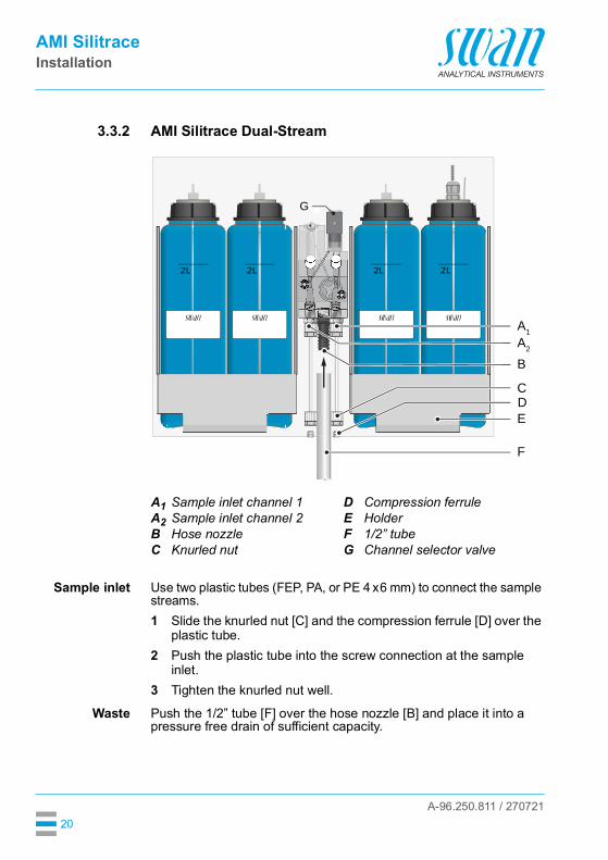
Sample inlet Use two plastic tubes (FEP, PA, or PE 4 x6 mm) to connect the sample streams.1 Slide the knurled nut [C] and the compression ferrule [D] over the
plastic tube.2 Push the plastic tube into the screw connection at the sample
inlet.3 Tighten the knurled nut well.
Waste Push the 1/2” tube [F] over the hose nozzle [B] and place it into a pressure free drain of sufficient capacity.
A1A2BC
Sample inlet channel 1Sample inlet channel 2Hose nozzleKnurled nut
DEFG
Compression ferruleHolder1/2” tubeChannel selector valve
A1
DE
G
C
F
BA2

A-96.250.811 / 270721
AMI SilitraceInstallation
21
3.4. Degassing Membrane (Option)
3.4.1 Scope of SupplyThe option includes the following items: Degassing membrane mounted on steel panel [B] with blind
plug [A] on the left port. Additional sample tube [C] 2-meter tube [D] for connection of the degassing membrane to
the vacuum pump
3.4.2 Additionally Required ItemsVacuum pump In addition to the items included in the delivery, a suitable vacuum
pump must be procured by the customer. The vacuum pump must guarantee a vacuum of at least -0.3 bar.The degassing membrane has been successfully tested with the following vacuum pump:
It is possible to use a different vacuum pump, but the characteristics should be similar to those of the tested pump.
Vacuummanometer
Optionally, it is possible to connect a manometer to the port on the left side of the degassing membrane. The port has an M6 female thread and is sealed with a blind plug when delivered.The vacuum manometer must be procured by the customer if required.
C DA B
Manufacturer:Type:
KnFLaboport N86KT.18
A-96.250.811 / 270721
AMI SilitraceInstallation
22
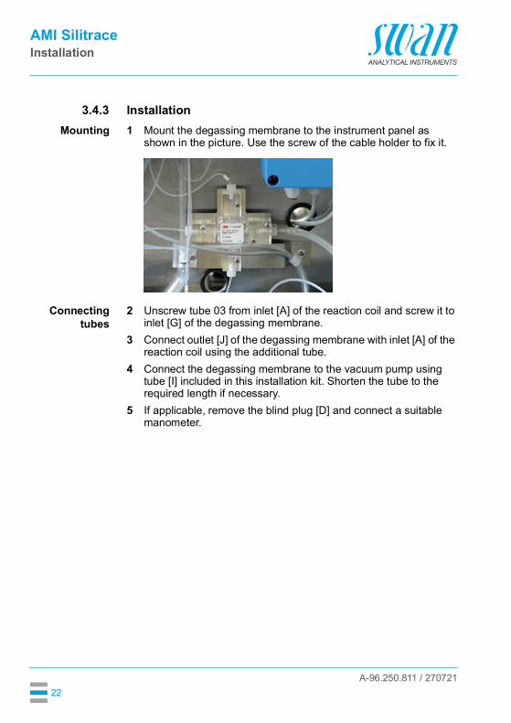
3.4.3 InstallationMounting 1 Mount the degassing membrane to the instrument panel as
shown in the picture. Use the screw of the cable holder to fix it.
Connectingtubes
2 Unscrew tube 03 from inlet [A] of the reaction coil and screw it to inlet [G] of the degassing membrane.
3 Connect outlet [J] of the degassing membrane with inlet [A] of the reaction coil using the additional tube.
4 Connect the degassing membrane to the vacuum pump using tube [I] included in this installation kit. Shorten the tube to the required length if necessary.
5 If applicable, remove the blind plug [D] and connect a suitable manometer.

A-96.250.811 / 270721
AMI SilitraceInstallation
23
Connectionoverview
ABCD
EF
Inlet of reaction coilAdditional sample tubePeristaltic pumpBlind plug / possibility to connect a manometerTube 02Tube 03
GHIJ
K
Inlet of degassing membraneDegassing membraneTube from vacuum pumpOutlet of degassing membranePhotometer
AB
C
E
F
D
H
G
I
K
J

A-96.250.811 / 270721
AMI SilitraceInstallation
24
3.5. Electrical Connections
WARNING
Risk of electrical shock.Do not perform any work on electrical components if the transmit-ter is switched on. Failure to follow safety instructions could result in serious injury or death. Always turn off AC power before manipulating electric parts. Grounding requirements: Only operate the instrument from a
power outlet which has a ground connection. Make sure the power specification of the instrument corre-
sponds to the power on site.
Cablethicknesses
In order to comply with IP66, use the following cable thicknesses:
Note: Protect unused cable glands
Wire For power and relays: Use max. 1.5 mm2 / AWG 14 stranded wire with end sleeves.
For signal outputs and input: Use 0.25 mm2 / AWG 23 stranded wire with end sleeves.
ABC
PG 11 cable gland: cable Øouter 5–10 mmPG 7 cable gland: cable Øouter 3–6.5 mmPG 9 cable gland: cable Øouter 4–8 mm
A B C
A-96.250.811 / 270721
AMI SilitraceInstallation
25
WARNING
External Voltage.External supplied devices connected to relay 1 or 2 or to the alarm relay can cause electrical shocks Make sure that the devices connected to the following contacts
are disconnected from the power before resuming installation.– relay 1– relay 2– alarm relay
WARNING
To prevent from electrical shock, do not connect the instrument to the power unless the ground wire (PE) is connected. Do not connect unless specifically instructed to do so.
WARNING
The mains of the AMI Transmitter must be secured by a main switch and appropriate fuse or circuit breaker.

A-96.250.811 / 270721
AMI SilitraceInstallation
26
3.5.1 Connection Diagram
CAUTION
Use only the terminals shown in this diagram, and only for the mentioned purpose. Use of any other terminals will cause short circuits with possible corresponding consequences to material and personnel.

A-96.250.811 / 270721
AMI SilitraceInstallation
27
3.5.2 Power Supply
WARNING
Risk of electrical shockDo not perform any work on electrical components if the transmit-ter is switched on. Failure to follow safety instructions could result in serious injury or death. Always turn off AC power before manipulating electric parts. Installation and maintenance of electrical parts must be per-
formed by professionals.
Note: The protective earth wire (ground) has to be connected to the grounding terminal.
Installationrequirements
The installation must meet the following requirements. Mains cable to comply with standards IEC 60227 or IEC
60245; flammable rating FV1 Mains equipped with an external switch or circuit-breaker
– near the instrument– easily accessible to the operator– marked as interrupter for AMI Silitrace
ABCD
Power supply connectorNeutral conductor, Terminal 2Phase conductor, Terminal 1Protective earth PE
A
B
C
D

A-96.250.811 / 270721
AMI SilitraceInstallation
28
3.6. Relay Contacts
3.6.1 InputNote: Use only potential-free (dry) contacts.The total resistance (sum of cable resistance and resistance of the relay contact) must be less than 50 Ω.
Terminals 16/42For programming see “Program List and Explanation” 5.3.4, p. 106.
3.6.2 Alarm RelayNote: Max. load 1 A/250 VAC
Alarm output for system errors. Error codes see Error List, p. 63.
Note: With certain alarms and certain settings of the AMI transmitter the alarm relay does not switch. The error, however, is shown on the display.
1) usual use
Terminals Description Relay connectionNC1)
Normally Closed
10/11 Active (opened) during normal operation.Inactive (closed) on error and loss of power.
NONormallyOpen
12/11 Active (closed) during normal operation.Inactive (opened) on error and loss of power.
10
12
11
0V
1)
10
12
11
0V
A-96.250.811 / 270721
AMI SilitraceInstallation
29
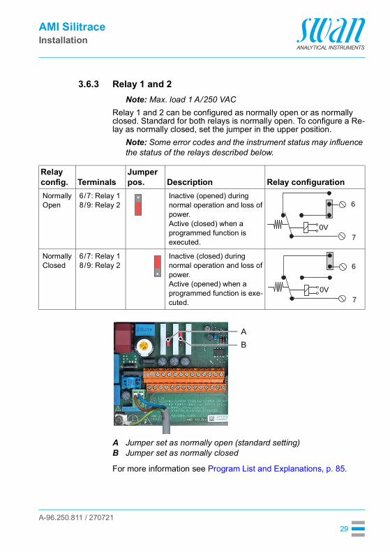
3.6.3 Relay 1 and 2Note: Max. load 1 A/250 VAC
Relay 1 and 2 can be configured as normally open or as normally closed. Standard for both relays is normally open. To configure a Re-lay as normally closed, set the jumper in the upper position.
Note: Some error codes and the instrument status may influence the status of the relays described below.
For more information see Program List and Explanations, p. 85.
Relay config. Terminals
Jumper pos. Description Relay configuration
NormallyOpen
6/7: Relay 18/9: Relay 2
Inactive (opened) during normal operation and loss of power.Active (closed) when a programmed function is executed.
NormallyClosed
6/7: Relay 18/9: Relay 2
Inactive (closed) during normal operation and loss of power.Active (opened) when a programmed function is exe-cuted.
6
0V7
6
0V7
AB
Jumper set as normally open (standard setting)Jumper set as normally closed
AB

A-96.250.811 / 270721
AMI SilitraceInstallation
30
CAUTION
Risk of damage of the relays in the AMI Transmitter due to heavy inductive load.Heavy inductive or directly controlled loads (solenoid valves, dos-ing pumps) may destroy the relay contacts. To switch inductive loads >0.1 A use an AMI relay box avail-
able as an option or suitable external power relays.
Inductive load Small inductive loads (max 0.1 A) as for example the coil of a power relay can be switched directly. To avoid noise voltage in the AMI Transmitter it is mandatory to connect a snubber circuit in paral-lel to the load. A snubber circuit is not necessary if an AMI relaybox is used.
Resistive load Resistive loads (max. 1 A) and control signals for PLC, impulse pumps and so on can be connected without further measures
Actuators Actuators, like motor valves, are using both relays: One relay contact is used for opening, the other for closing the valve, i.e. with the 2 relay contacts available, only one motor valve can be con-trolled. Motors with loads bigger than 0.1 A must be controlled via external power relays or an AMI relay box.
ABCDE
AC or DC power supplyAMI TransmitterExternal power relaySnubberPower relay coil
AB C
D E
ABC
AMI TransmitterPLC or controlled pulse pumpLogic
A B
C
ABC
AC or DC power supplyAMI TransmitterActuator
M
AB C
A-96.250.811 / 270721
AMI SilitraceInstallation
31
3.7. Signal Outputs
3.7.1 Signal Output 1 and 2 (current outputs)Note: Max. burden 510 Ω.If signals are sent to two different receivers, use signal isolator (loop isolator).
Signal output 1: Terminals 14 (+) and 13 (-)Signal output 2: Terminals 15 (+) and 13 (-)For programming see Program List and Explanations, p. 85, Menu Installation.
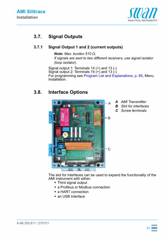
3.8. Interface Options
The slot for interfaces can be used to expand the functionality of the AMI instrument with either: Third signal output a Profibus or Modbus connection a HART connection an USB Interface
ABC
AMI TransmitterSlot for interfacesScrew terminals
A
B
C
A-96.250.811 / 270721
AMI SilitraceInstallation
32
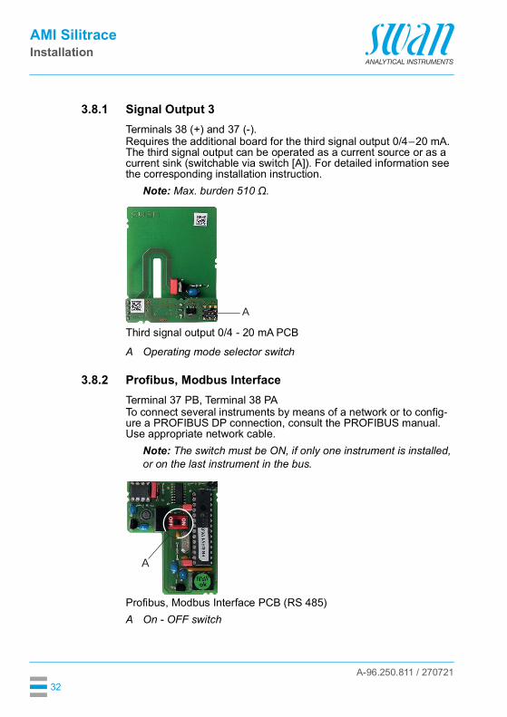
3.8.1 Signal Output 3Terminals 38 (+) and 37 (-).Requires the additional board for the third signal output 0/4–20 mA. The third signal output can be operated as a current source or as a current sink (switchable via switch [A]). For detailed information see the corresponding installation instruction.
Note: Max. burden 510 Ω.
Third signal output 0/4 - 20 mA PCB
3.8.2 Profibus, Modbus InterfaceTerminal 37 PB, Terminal 38 PATo connect several instruments by means of a network or to config-ure a PROFIBUS DP connection, consult the PROFIBUS manual. Use appropriate network cable.
Note: The switch must be ON, if only one instrument is installed, or on the last instrument in the bus.
Profibus, Modbus Interface PCB (RS 485)
A Operating mode selector switch
A
A On - OFF switch
ON
OFF
A

A-96.250.811 / 270721
AMI SilitraceInstallation
33
3.8.3 HART InterfaceTerminals 38 (+) and 37 (-).The HART interface PCB allows for communication via the HART protocol. For detailed information, consult the HART manual.
HART Interface PCB
3.8.4 USB InterfaceThe USB Interface is used to store Logger data and for Firmware up-load. For detailed information see the corresponding installation in-struction.The optional third signal output 0/4 – 20 mA PCB [B] can be plugged onto the USB interface and used in parallel.
USB Interface
A USB interface PCBB Third signal output 0/4 - 20 mA PCB
A
B

A-96.250.811 / 270721
AMI SilitraceInstrument Setup
34
4. Instrument Setup
4.1. Start-up ProcedureThe following table lists all necessary steps for a successful commis-sioning of the AMI Silitrace. Additionally, the expected result and cor-rective actions are specified for each step. It is important to verify the result of each step before proceeding with the next step. We recommend to work exactly in the order given in the table.
Prerequisites Analyzer has been mounted, connected to the sample and waste line and connected to power (see Installation, p. 17).
Optional: AMI Sample Sequencer has been installed (see manual of the AMI Sample Sequencer).
Step Expected result Corrective actionPrepare Reagents 36,Prepare Standard 36
n/a n/a
Switch on Power 38 The AMI transmitter starts up.
The main screen is displayed.
Check electrical wiring. Check fuses.
If present, switch on the vacuum pump of the degassing membrane.
n/a n/a
Adjust Sample Flow 38 (approx. 5–10 l/h)
The flow is indicated on the main screen.
Check sample line. Check wiring of flow
sensor.
Activate the Peristaltic Pump 40, Fill System 40
The tubes are filled. The liquid moves with a
speed of approximately 1 cm every 5 s.
Tighten connections to the pump tubes.
Check if occlusion frames are snapped properly.
Check if occlusion frames and pump tubes are aligned in a 90° angle to the rotor.
Programming 41 n/a n/a

A-96.250.811 / 270721
AMI SilitraceInstrument Setup
35
Resolve all pending errors No errors are displayed apart from E008 “SilTrace temp low”.
As soon as the reaction chamber has reached its operating temperature, E008 automatically disappears.
If there are other pending errors, resolve them according to the Error List 63.
Visual check of the reac-tion chamber 42
No air bubbles in the reaction chamber.
Tighten all tube connections.
Check photometer raw value 43
The photometer’s raw value follows a fill/empty pattern.
While the photometer is being filled, an unstable raw value is normal.
Once the cuvette is completely filled, the raw value must remain stable.
Cuvette blocked. Cuvette not snapped
completely.
Check P2P period 43 P2P period is different from “0 Sec”.
Wait until the system is free from air bubbles.
Wait until the cuvette has been emptied twice.
Perform a zero calibration 58
The raw value is close to 2.2 V.
Clean cuvette / flush system with ammonia solution 62.
Perform a cuvette factor determination 90.
Check if the zero calibration valve is switching.
Perform a standard cali-bration 56
The calibration factor is between 0.5 and 2.0.
Check programmed concentration of standard.
Repeat calibration with fresh standard solution.
Step Expected result Corrective action
A-96.250.811 / 270721
AMI SilitraceInstrument Setup
36
4.2 Prepare ReagentsPrepare reagents according to Refill or Replace Reagents, p. 53.Insert the suction lances into the containers. Make sure that the numbers on the suction lances correspond to the numbers on the containers.
4.3. Prepare StandardThe following standard solutions are available: 100 ppb standard in a 250 ml bottle 100 ppm stock solution in a 100 ml bottle
Standard100 ppb
Ready for use.
Stock solution100 ppm
From the stock solution you can produce your own standard. Stan-dards from 10 to 1000 ppb can be used for the AMI Silitrace.SWAN does not recommend to mix your own standard!By default the instrument is programmed for a standard of 100 ppb.
Note: If you prepare a standard different from 100 ppb, program the standard concentration in menu <Installation>/<Sensors>/<Meas. Parameters>/<Cal./Verif.>/<Standard>.
Make the following dilution to obtain a standard of 100 ppb:1 Put a 250 ml bottle on to a balance, set balance to 0 g.2 Fill in 250 µg stock solution 100 ppm.3 Fill up to 250 g with demineralized water.4 Mark the bottle with the correct concentration.5 Program the instrument accordingly, see 5.1.1.1.1, p. 92.
A-96.250.811 / 270721
AMI SilitraceInstrument Setup
37
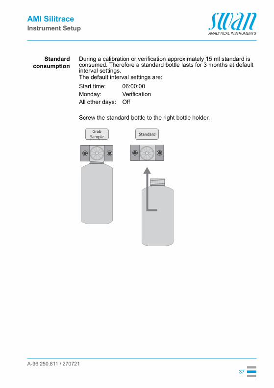
Standardconsumption
During a calibration or verification approximately 15 ml standard is consumed. Therefore a standard bottle lasts for 3 months at default interval settings.The default interval settings are:
Screw the standard bottle to the right bottle holder.
Start time: 06:00:00Monday: VerificationAll other days: Off
StandardGrab
Sample

A-96.250.811 / 270721
AMI SilitraceInstrument Setup
38
4.4. Switch on PowerOpen the sample tap and switch on the instrument.
After switching on, the instrument starts to warm up the reaction chamber. During the warm-up phase, the display shows <INIT> and alarm E008 is active.
Note: The duration of the warm-up phase depends on the ambient temperature at the operating site.
After the reaction chamber has reached its operating temperature, the instrument changes to <RUN> and is ready for operation.
4.5. Adjust Sample FlowAMI Silitrace
1 Open the flow regulating valve [A].2 Adjust the sample flow to 5–10 l/h
INITR1
R2 ppb0.00.0 °C5.0 l/h
AB
Flow regulating valveOverflowA
B
A-96.250.811 / 270721
AMI SilitraceInstrument Setup
39
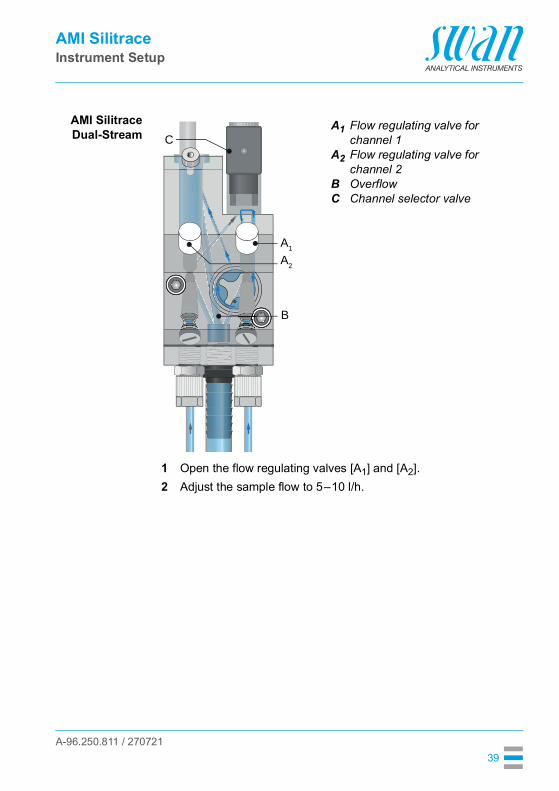
AMI SilitraceDual-Stream
1 Open the flow regulating valves [A1] and [A2].2 Adjust the sample flow to 5–10 l/h.
A1
A2
BC
Flow regulating valve for channel 1Flow regulating valve for channel 2OverflowChannel selector valve
B
C
A1
A2

A-96.250.811 / 270721
AMI SilitraceInstrument Setup
40
4.6. Activate the Peristaltic pumpThe occlusion frames of the peristaltic pump are opened during transport and storage. This prevents the pump tubes from sticking to-gether at the pressure points.
1 Turn the occlusion frames [B] clockwise until they snap in to acti-vate the peristaltic pump.Note: Make sure the occlusion frames and pump tubes are aligned in a 90° angle to the rotor.
Fill System Select <Maintenance>/<Service>/<Fill system>. This activates the reagent pump and fills all tubes from the container to the cuvette out-let.
ABCD
Turn to lockOcclusion frameRotorPump tube
A
B
DC

A-96.250.811 / 270721
AMI SilitraceInstrument Setup
41
4.7. ProgrammingProgram all parameters for external devices (interface, recorders, etc.). and for instrument operation (limits, alarms).See Program List and Explanations, p. 85.
If an AMI Sample Sequencer is installed, make the following settings: Settings in the <Installation>/<Sequence> menu of the
AMI Sample Sequencer:– Select mode “AMI”.
Settings in the <Installation>/<Sensors>/<Multi-Channel> menu of the AMI analyzer:– Set the number of available channels.– Set the channel selection mode
For detailed descriptions of the channel selection modes, see the following sections:Mode Internal, p. 94Mode Fieldbus, p. 94Mode External, p. 95
A-96.250.811 / 270721
AMI SilitraceInstrument Setup
42
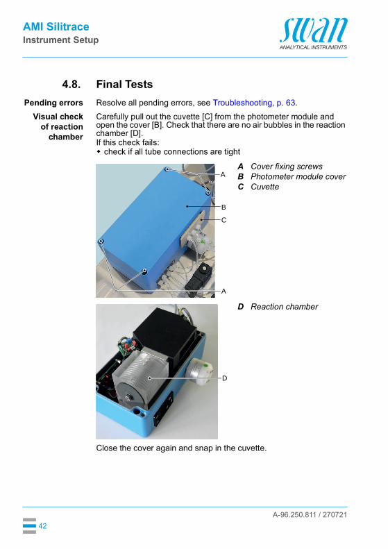
4.8. Final TestsPending errors Resolve all pending errors, see Troubleshooting, p. 63.
Visual checkof reaction
chamber
Carefully pull out the cuvette [C] from the photometer module and open the cover [B]. Check that there are no air bubbles in the reaction chamber [D]. If this check fails: check if all tube connections are tight
Close the cover again and snap in the cuvette.
ABC
Cover fixing screwsPhotometer module coverCuvette
D Reaction chamber
A
B
C
A
D
A-96.250.811 / 270721
AMI SilitraceInstrument Setup
43
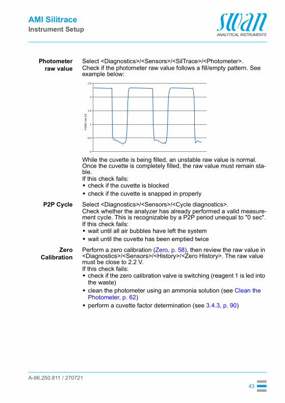
Photometerraw value
Select <Diagnostics>/<Sensors>/<SilTrace>/<Photometer>.Check if the photometer raw value follows a fill/empty pattern. See example below:
While the cuvette is being filled, an unstable raw value is normal. Once the cuvette is completely filled, the raw value must remain sta-ble.If this check fails: check if the cuvette is blocked check if the cuvette is snapped in properly
P2P Cycle Select <Diagnostics>/<Sensors>/<Cycle diagnostics>.Check whether the analyzer has already performed a valid measure-ment cycle. This is recognizable by a P2P period unequal to "0 sec".If this check fails: wait until all air bubbles have left the system wait until the cuvette has been emptied twice
ZeroCalibration
Perform a zero calibration (Zero, p. 58), then review the raw value in <Diagnostics>/<Sensors>/<History>/<Zero History>. The raw value must be close to 2.2 V.If this check fails: check if the zero calibration valve is switching (reagent 1 is led into
the waste) clean the photometer using an ammonia solution (see Clean the
Photometer, p. 62) perform a cuvette factor determination (see 3.4.3, p. 90)
0
0.5
1
FOM
E ra
w [V
]
1.5
2
2.5

A-96.250.811 / 270721
AMI SilitraceInstrument Setup
44
StandardCalibration
Perform a standard calibration (Calibration, p. 56), then review the calibration factor in <Diagnostics>/<Sensors>/<Cal. History>. The calibration factor must be between 0.5 and 2.0.If this check fails: Check if the programmed concentration matches the reference
value of the standard solution Repeat the calibration with a new standard solution

A-96.250.811 / 270721
AMI SilitraceOperation
45
5. Operation
5.1. Keys
ProgramAccess, Exit
A to exit a menu or command (rejecting any changes)to move back to the previous menu level
B to move DOWN in a menu list and to decrease digitsC to move UP in a menu list and to increase digits
to switch between display 1 and 2D to open a selected sub-menu
to accept an entry
Exit Enter
B C DA
25.4°C
RUN
9 l/h
14:10:45R1 1.4 ppbR2
1
InstallationOperation
DiagnosticsMessages
Maintenance
Main MenuEnter
Exit

A-96.250.811 / 270721
AMI SilitraceOperation
46
5.2. Display
Relay status, symbols
A INIT Warming up the reaction chamber
RUN normal operation
HOLD input closed or cal delay: Instrument on hold (shows status of signal outputs).
OFF input closed: control/limit is interrupted (shows status of signal outputs).
GRAB A grab sample measurement is in progress.
B ERROR Error Fatal Error
C Reagent low, indicates remaining reagents in % (17% = 340 ml)
D Keys locked, transmitter control via Profibus
E Time
F Process value with time stamp
G Reaction chamber temperature
H Sample flow
I Relay status
upper/lower limit not yet reachedupper/lower limit reachedcontrol upw./downw. no action
control upw./downw. active, dark bar indicates control intensity
motor valve closedmotor valve: open, dark bar indicates approx. positiontimertimer: timing active (hand rotating)channel selection (Dual-Stream variant) or controlled via Profibus
RUN 15:20:18
R1
R2
45.1 °C5 l/h
ppb4.7
A B D
FGH
I
EC
15:10:52
A-96.250.811 / 270721
AMI SilitraceOperation
47
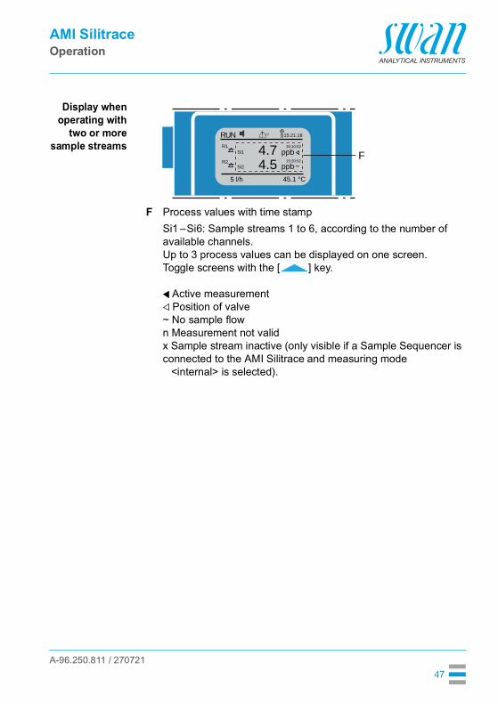
Display whenoperating with
two or moresample streams
F Process values with time stampSi1 –Si6: Sample streams 1 to 6, according to the number of available channels.Up to 3 process values can be displayed on one screen. Toggle screens with the [ ] key.
Active measurementPosition of valve
~ No sample flown Measurement not validx Sample stream inactive (only visible if a Sample Sequencer is connected to the AMI Silitrace and measuring mode
<internal> is selected).
RUN 15:21:18
15:10:52
15:20:52
R1Si1
Si2R2
45.1 °C5 l/h
ppb~4.5ppb4.7 F

A-96.250.811 / 270721
AMI SilitraceOperation
48
5.3. Software Structure
Menu Messages 1Reveals pending errors as well as an event history (time and state of events that have occurred at an earlier point of time). It contains user relevant data.
Menu Diagnostics 2Provides user relevant instrument and sample data.
Menu Maintenance 3For instrument calibration, relay and signal output simulation, and to set the instrument time. It is used by the service personnel.
Menu Operation 4User relevant parameters that might need to be modified during daily routine. Normally password protected and used by the process-operator.Subset of menu 5 - Installation, but process-related.
Menu Installation 5For initial instrument set up by SWAN authorized person, to set all instrument parameters. Can be protected by means of password.
1
Messages
OperationMaintenanceDiagnostics
Main Menu
Installation
1.1
Pending ErrorsMessages
Maintenance ListMessage List
2.1
InterfaceI/O StateSample
IdentificationSensors
Diagnostics
3.1
CalibrationVerification
Maintenance
ServiceZero
Simulation
4.1
LoggerRelay ContactsSensors
OperationGrab Sample
5.1
Interface
Relay Contacts
SensorsSignal Outputs
Installation

A-96.250.811 / 270721
AMI SilitraceOperation
49
5.4. Changing Parameters and valuesChanging
parametersThe following example shows how to change the logger interval:
Changingvalues
1 Select the parameter you want to change.
2 Press [Enter]
3 Press [ ] or [ ] key to highlight the required parameter.
4 Press [Enter] to confirm the selec-tion or [Exit] to keep the previous pa-rameter).
The selected parameter is highlighted but not saved yet.
5 Press [Exit].
Yes is highlighted.6 Press [Enter] to save the new pa-
rameter. The system reboots, the new
parameter is set.
5.1.2SensorsSensor type FOME
Temperature NT5KStandards
Disinf. Free chlorine
4.4.1LoggerLog interval 30 minClear logger no
4.1.3Logger
Clear logger noLog interval 30min
1 Hour
Interval.5 min
30 min10 min
4.1.3LoggerLog interval 10 minClear logger no
4.1.3LoggerLog intervalClear logger no
No
Save ?Yes
1 Select the value you want to change.
2 Press [Enter].3 Set required value with [ ] or
[ ] key.
4 Press [Enter] to confirm the new val-ue.
5 Press [Exit]. Yes is highlighted.
6 Press [Enter] to save the new value.
5.3.1.1.1
Alarm High 1.00 ppmAlarm Si 1
Alarm Low 0.0 ppbHysteresis 5.0 ppbDelay 5 Sec
5.3.1.1.1Alarm Si 1
Alarm Low 0.0 ppbHysteresis 5.0 ppbDelay 5 Sec
Alarm High 0.70 ppm

A-96.250.811 / 270721
AMI SilitraceOperation
50
5.5. Grab Sample MeasurementNote: • The grab sample function is not suitable for quality assurance
of the instrument.• Older versions of the AMI Silitrace have only one holder for the
standard bottle, but no holder for a grab sample bottle. With such instruments, connect an additional tube to port 2 of the 6-way valve.
Select Menu 4.1 (<Operation>/<Grab Sample>) and follow the instructions on the display.Relay status during grab sample measurement: Signal outputs are on hold All limits are switched off
1 Close the flow regulating valve.2 Fill the sample into the grab sample
bottle and screw it to the left bottle holder.
3 Press [Enter].
4.1.5
Grab Sample bottle
Grab Sample
to marked holder
Connect the
<Enter> to continue
StandardGrab
Sample
A-96.250.811 / 270721
AMI SilitraceOperation
51
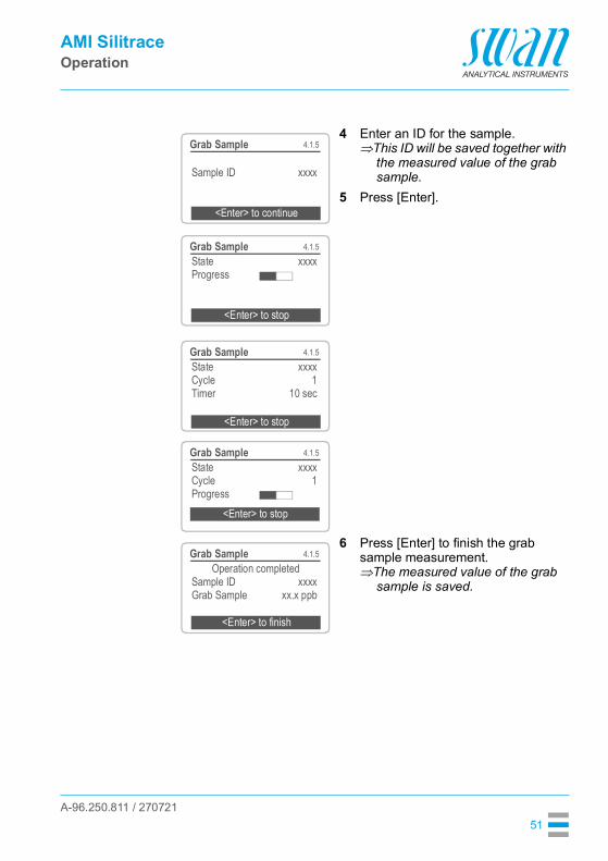
4 Enter an ID for the sample.This ID will be saved together with
the measured value of the grab sample.
5 Press [Enter].
6 Press [Enter] to finish the grab sample measurement.The measured value of the grab
sample is saved.
4.1.5Grab Sample
Sample ID xxxx
<Enter> to continue
4.1.5Grab SampleState xxxxProgress
<Enter> to stop
4.1.5Grab SampleState xxxxCycle 1Timer 10 sec
<Enter> to stop
4.1.5Grab SampleState xxxxCycle 1Progress
<Enter> to stop
4.1.5Grab SampleOperation completed
Sample ID xxxxGrab Sample xx.x ppb
<Enter> to finish
A-96.250.811 / 270721
AMI SilitraceMaintenance
52
6. Maintenance
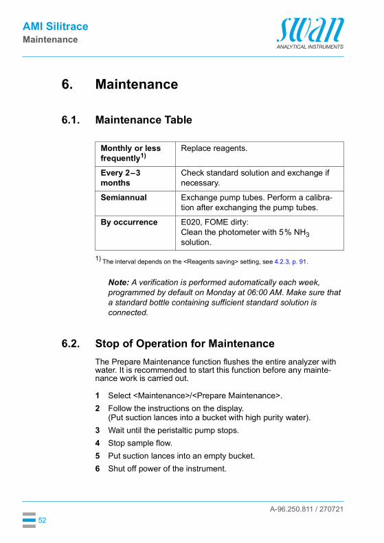
6.1. Maintenance Table
1) The interval depends on the <Reagents saving> setting, see 4.2.3, p. 91.
Note: A verification is performed automatically each week, programmed by default on Monday at 06:00 AM. Make sure that a standard bottle containing sufficient standard solution is connected.
6.2. Stop of Operation for MaintenanceThe Prepare Maintenance function flushes the entire analyzer with water. It is recommended to start this function before any mainte-nance work is carried out.
1 Select <Maintenance>/<Prepare Maintenance>.2 Follow the instructions on the display.
(Put suction lances into a bucket with high purity water).3 Wait until the peristaltic pump stops.4 Stop sample flow.5 Put suction lances into an empty bucket.6 Shut off power of the instrument.
Monthly or less frequently1)
Replace reagents.
Every 2–3 months
Check standard solution and exchange if necessary.
Semiannual Exchange pump tubes. Perform a calibra-tion after exchanging the pump tubes.
By occurrence E020, FOME dirty:Clean the photometer with 5% NH3 solution.

A-96.250.811 / 270721
AMI SilitraceMaintenance
53
6.3. Refill or Replace ReagentsThe liquid level in container 4 is monitored. The following messages are displayed:
WARNINGHealth hazard For safe handling of the reagents you must read and under-
stand the Material Safety Data Sheets (MSDS). Only persons trained in handling dangerous chemicals are
allowed to prepare the reagents.Canister setup
Reagentconsumption
Each 2 liter reagent canister will last for approximately 1 month of operation if reagent saving is switched off or up to three months if reagent saving is switched on (see 4.2.3, p. 91).
Note: Excessive use of the flush/fill function or frequent flow interruptions will shorten this period.
Container almost empty
Maintenance E065 - Reagents low and the remaining reagent volume in % (starting at 17 % = 340 ml).
Container empty Error E022 - Reagent empty
A
B
CDEFGHI
Suction lance without level detector (containers 1–3)Suction lance with level detector (container 4)Level detector2 L markReagent container 1Reagent container 2Reagent container 3Reagent container 4Holder
A
B
C
ED
F
G
IH

A-96.250.811 / 270721
AMI SilitraceMaintenance
54
Contents of thereagent set
Reagent 1: Bags 1a and 1b for Canister 1ammonium molybdate and sodium hydroxyde
Reagent 2: Bottle 2 for Canister 2sulfuric acid 25%
Reagent 3: Bag 3 for Canister 3oxalic acid dihydrate
Reagent 4: Bag 4a and bottle 4b for Canister 4ammonium ferrous sulfate hexahydrate sulfuric acid 25% containing detergent
Reagent filters (12x)
WARNINGSulfuric acid is corrosive and causes severe burns. Read the Material Safety Data Sheets (MSDS) first. Only persons trained in handling dangerous chemicals are
allowed to prepare the reagents In case of contact with eyes, rinse immediately with plenty of water
eyelid wide open, summon medical advice. In case of accident or if you feel unwell, summon medical advice immediately.
Note: Never prepare this reagent from concentrated sulfuric acid packed in glass bottles!
Warning
Reagent 3:H302: Harmful if swallowed H312: Harmful in contact with skin
Warning
Reagent 4a:H315: Causes skin irritationH319: Causes serious eye irritationH335: May cause respiratory irritation
Danger
Reagent 1b, Reagent 2, Reagent 4b:H314: Causes severe skin burns and eye damage
A-96.250.811 / 270721
AMI SilitraceMaintenance
55
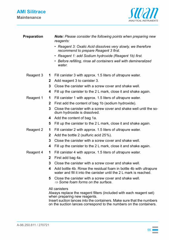
Preparation Note: Please consider the following points when preparing new reagents:• Reagent 3: Oxalic Acid dissolves very slowly, we therefore
recommend to prepare Reagent 3 first.• Reagent 1: add Sodium hydroxide (Reagent 1b) first.• Before refilling, rinse all containers well with demineralized
water.
Reagent 3 1 Fill canister 3 with approx. 1.5 liters of ultrapure water.2 Add reagent 3 to canister 3.3 Close the canister with a screw cover and shake well.4 Fill up the canister to the 2 L mark, close it and shake again.
Reagent 1 1 Fill canister 1 with approx. 1.5 liters of ultrapure water.2 First add the content of bag 1b (sodium hydroxide).3 Close the canister with a screw cover and shake well until the so-
dium hydroxide is dissolved.4 Add the content of bag 1a.5 Fill up the canister to the 2 L mark, close it and shake again.
Reagent 2 1 Fill canister 2 with approx. 1.5 liters of ultrapure water.2 Add the bottle 2 (sulfuric acid 25%).3 Close the canister with a screw cover and shake well.4 Fill up the canister to the 2 L mark, close it and shake again.
Reagent 4 1 Fill canister 4 with approx. 1.5 liters of ultrapure water.2 First add bag 4a.3 Close the canister with a screw cover and shake well.4 Add bottle 4b. Rinse the residual foam in bottle 4b with ultrapure
water and fill it into the canister until the 2 L mark is reached.5 Close the canister with a screw cover and shake well.
Some foam forms on the surface.
All canistersAlways replace the reagent filters (included with each reagent set) when preparing new reagents.Insert suction lances into the containers. Make sure that the numbers on the suction lances correspond to the numbers on the containers.

A-96.250.811 / 270721
AMI SilitraceMaintenance
56
6.4. CalibrationSelect Menu 3.1 <Maintenance>/<Calibration> and follow the in-structions on the display.Relay status during calibration: Signal outputs are on hold All limits are switched off
Press [Enter] to save the value in the calibration history or leave the menu with [Exit].
4.1.5
standard bottle
Calibration
to marked holder
Connect the
<Enter> to continue
3.1.1CalibrationState xxxxProgress
<Enter> to stop
3.1.1CalibrationState SynchronizeCycle 1Timer 10 sec
<Enter> to stop
3.1.1CalibrationState MeasureCycle 1Progress
<Enter> to stop
3.1.1CalibrationOperation completed
Factor xxxx
<Enter> to save

A-96.250.811 / 270721
AMI SilitraceMaintenance
57
6.5. VerificationSelect Menu 3.2 <Maintenance>/<Verification> and follow the in-structions on the display.Relay status during verification: Signal outputs are on hold All limits are switched off
Press [Enter] to save the value in the verification history or leave the menu with [Exit].
4.1.5
standard bottle
Verification
to marked holder
Connect the
<Enter> to continue
3.2.1VerificationState xxxxProgress
<Enter> to stop
3.2.1VerificationState SynchronizeCycle 1Timer 10 sec
<Enter> to stop
3.2.1VerificationState MeasureCycle 1Progress
<Enter> to stop
3.2.1VerificationOperation completed
Current value xxx ppbReference value xxx ppb
<Enter> to saveDeviation xx.x%
A-96.250.811 / 270721
AMI SilitraceMaintenance
58
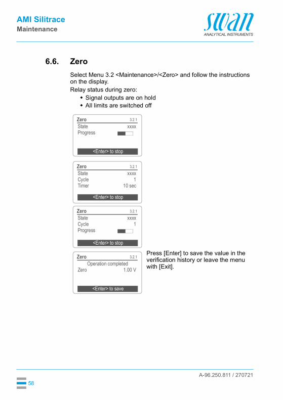
6.6. ZeroSelect Menu 3.2 <Maintenance>/<Zero> and follow the instructions on the display.Relay status during zero: Signal outputs are on hold All limits are switched off
Press [Enter] to save the value in the verification history or leave the menu with [Exit].
3.2.1ZeroState xxxxProgress
<Enter> to stop
3.2.1ZeroState xxxxCycle 1Timer 10 sec
<Enter> to stop
3.2.1ZeroState xxxxCycle 1Progress
<Enter> to stop
3.2.1ZeroOperation completed
Zero 1.00 V
<Enter> to save
A-96.250.811 / 270721
AMI SilitraceMaintenance
59
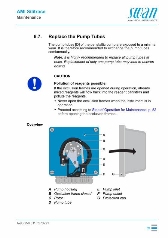
6.7. Replace the Pump TubesThe pump tubes [D] of the peristaltic pump are exposed to a minimal wear. It is therefore recommended to exchange the pump tubes semiannually.
Note: it is highly recommended to replace all pump tubes at once. Replacement of only one pump tube may lead to uneven dosing.
CAUTION
Pollution of reagents possible.If the occlusion frames are opened during operation, already mixed reagents will flow back into the reagent canisters and pollute the reagents. Never open the occlusion frames when the instrument is in
operation. Proceed according to Stop of Operation for Maintenance, p. 52
before opening the occlusion frames.
Overview
ABCD
Pump housingOcclusion frame closedRotorPump tube
EFG
Pump inletPump outletProtection cap
A
B
D
C
E
F G

A-96.250.811 / 270721
AMI SilitraceMaintenance
60
Dismountpump tubes
The pump tubes can easily be dismounted and mounted. Proceed as follows:
1 Switch off the instrument according to instructions in Stop of Op-eration for Maintenance, p. 52.
2 Remove the protection cap.3 Open the occlusion frames [B] by turning them counterclockwise.4 Remove the pump tubes [D] from the rotor [C] by pulling the com-
plete occlusion frames [B] out of the holder.5 Disconnect the reagent tubes from the old pump tubes and con-
nect them to the new pump tubes6 Install the new pump tubes by pushing the occlusion frames onto
the holder.7 Lock the occlusion frames. Check that the occlusion frames and
the tubes are aligned perpendicular to the axis of the rotor.Note: The tube nearest to the housing (sample tube) has a diameter of 2.8 mm. All other tubes have a diameter of 0.64 mm.
8 Insert the suction lances into the corresponding containers.9 Start the <Fill system> function.
ABCDEF
Pump housingOcclusion frame openRotorPump tubePump inletPump outlet
AB
DC
EF
Ø =
2.8
mm
Ø =
0.6
4 m
m
Ø =
0.6
4 m
m
Ø =
0.6
4 m
m
Ø =
0.6
4 m
m

A-96.250.811 / 270721
AMI SilitraceMaintenance
61
6.8. Fill SystemFill the reagent tubing: at first start-up after refilling the reagent containers after replacing the pump tubes
Navigate to menu <Maintenance /Service/Fill system>.Press [Enter].
The peristaltic pump is activated for 1.5 minutes.
Press [Exit] 4 times to return to the operating display mode.
3.2.2
Fill SystemService
Prepare Maintenance
3.2.2.5Fill System
Progress
<Enter> to stop
3.2.2.5Fill System
Progress
Done
A-96.250.811 / 270721
AMI SilitraceMaintenance
62
6.9. Clean the PhotometerTo clean the photometer, flush it with 5% ammonia solution.
CAUTION
If the optional degassing membrane is installed, it must be bypassed during flushing with ammonia solution. Otherwise, the membrane will be damaged.
1 Fill a beaker with 5% ammonia solution.2 Place all suction lances in the beaker.3 Navigate to menu <Maintenance>/<Service>/<Fill system>.4 Press [Enter].
6.10. Longer Stop of Operation
1 Proceed according to chapter Stop of Operation for Maintenance, p. 52.
2 Relax the occlusion frames of the Peristaltic pump.See Replace the Pump Tubes, p. 59.
A-96.250.811 / 270721
AMI SilitraceTroubleshooting
63
7. Troubleshooting
7.1. Error List
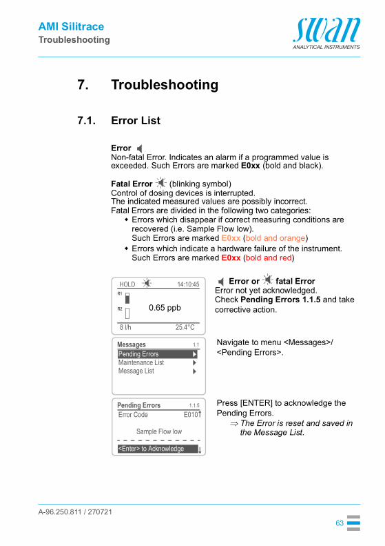
Error Non-fatal Error. Indicates an alarm if a programmed value is exceeded. Such Errors are marked E0xx (bold and black).
Fatal Error (blinking symbol)Control of dosing devices is interrupted.The indicated measured values are possibly incorrect.Fatal Errors are divided in the following two categories: Errors which disappear if correct measuring conditions are
recovered (i.e. Sample Flow low).Such Errors are marked E0xx (bold and orange)
Errors which indicate a hardware failure of the instrument.Such Errors are marked E0xx (bold and red)
Error or fatal ErrorError not yet acknowledged.Check Pending Errors 1.1.5 and take corrective action.
Navigate to menu <Messages>/<Pending Errors>.
Press [ENTER] to acknowledge the Pending Errors.
The Error is reset and saved in the Message List.
25.4°C
HOLD
8 l/h
14:10:45R1
0.65 ppbR2
1.1
Message ListMaintenance ListPending ErrorsMessages
1.1.5Pending ErrorsError Code E010
Sample Flow low
<Enter> to Acknowledge
A-96.250.811 / 270721
AMI SilitraceTroubleshooting
64
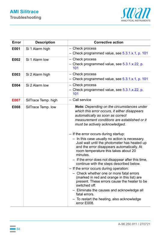
Error Description Corrective actionE001 Si 1 Alarm high – Check process
– Check programmed value, see 5.3.1.x.1, p. 101
E002 Si 1 Alarm low – Check process– Check programmed value, see 5.3.1.x.22, p.
101
E003 Si 2 Alarm high – Check process– Check programmed value, see 5.3.1.x.1, p. 101
E004 Si 2 Alarm low – Check process– Check programmed value, see 5.3.1.x.22, p.
101
E007 SilTrace Temp. high – Call service
E008 SilTrace Temp. low Note: Depending on the circumstances under which this error occurs, it either disappears automatically as soon as correct measurement conditions are established or it must be actively acknowledged.
– If the error occurs during startup:– In this case usually no action is necessary.
Just wait until the photometer has heated up and the error disappears automatically. At room temperature this takes about 20 minutes.
– If the error does not disappear after this time, continue with the steps described below.
– If the error occurs during operation:– Check whether one or more fatal errors
(marked in red and orange in this list) are present. These errors cause the heater to be switched off.
– Eliminate the causes and acknowledge all fatal errors.
– To restart the heating, also acknowledge error E008.
A-96.250.811 / 270721
AMI SilitraceTroubleshooting
65
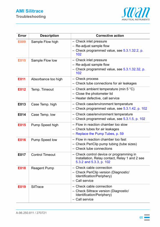
E009 Sample Flow high – Check inlet pressure– Re-adjust sample flow– Check programmed value, see 5.3.1.32.2, p.
102
E010 Sample Flow low – Check inlet pressure– Re-adjust sample flow– Check programmed value, see 5.3.1.32.32, p.
102
E011 Absorbance too high – Check process– Check tube connections for air leakages
E012 Temp. Timeout – Check ambient temperature (min 5 °C)– Close the photometer lid– Heater defective, call service
E013 Case Temp. high – Check case/environment temperature– Check programmed value, see 5.3.1.42, p. 102
E014 Case Temp. low – Check case/environment temperature– Check programmed value, see 5.3.1.5, p. 102
E015 Pump Speed high – Flow in reaction chamber too slow– Check tubes for air leakages– Replace the Pump Tubes, p. 59
E016 Pump Speed low – Flow in reaction chamber too fast– Check PeriClip pump tubing (tube sizes)– Check tube connections
E017 Control Timeout – Check control device or programming in Installation, Relay contact, Relay 1 and 2 see 5.3.2 and 5.3.3, p. 102
E018 Reagent Pump – Check cable connection– Check PeriClip version (Diagnostic/
Identification/Periphery)– Call service
E019 SilTrace – Check cable connection– Check Siltrace version (Diagnostic/
Identification/Periphery)– Call service
Error Description Corrective action

A-96.250.811 / 270721
AMI SilitraceTroubleshooting
66
E020 Photometer dirty – Cuvette dirty– Clean cuvette lenses with a tissue– Replace the Cuvette, p. 72.
E021 Signal Timeout – Unsuccessful peak detection can be caused by:1) interrupted light path2) no water/too much air in the
reaction chamber– Check if reaction chamber is clogged, replace it
if necessary, see Replace the reaction chamber, p. 68.
– Check position of the cuvette (make sure that it is pushed into the slot as far as it will go)
– Check tube connections
E022 Reagent empty – Refill reagents, see Refill or Replace Reagents, p. 53.
E023 Sequencer – Check Sample Sequencer connection.– Make sure that the Sample Sequencer is set to
the mode “AMI” (menu <Installation>/<Sequence>/<Mode>).
– This error message also appears during programming of the Sample Sequencer when the <Installation> menu is entered.
E024 Input active – No action necessary.– This message is displayed if “Fault = Yes” is
programmed, see 5.3.4, p. 106.
E025 Rovalve (6-way valve) – Check cable connection, see Electrical Connections, p. 24.
– Replace the 6-Way Valve, p. 70.
E026 IC LM75 – Call service
E028 Signal output open – Check wiring on signal outputs 1 and 2
E030 EEProm Frontend – Call service
E031 Cal. Recout – Call service
E032 Wrong Frontend – Call service
Error Description Corrective action

A-96.250.811 / 270721
AMI SilitraceTroubleshooting
67
E033 Sample Flow 1 low (multi-channel instru-ments)
– Check inlet pressure– Re-adjust sample flow– Check programmed value, see 5.3.1.32.2, p.
102
E034 Sample Flow 2 low (multi-channel instru-ments)
– Check inlet pressure– Re-adjust sample flow– Check programmed value, see 5.3.1.32.2, p.
102
E035 Sample Flow 3 low (multi-channel instru-ments)
– Check inlet pressure– Re-adjust sample flow– Check programmed value, see 5.3.1.32.2, p.
102
E036 Sample Flow 4 low (multi-channel instru-ments)
– Check inlet pressure– Re-adjust sample flow– Check programmed value, see 5.3.1.32.2, p.
102
E037 Sample Flow 5 low (multi-channel instru-ments)
– Check inlet pressure– Re-adjust sample flow– Check programmed value, see 5.3.1.32.2, p.
102
E038 Sample Flow 6 low (multi-channel instru-ments)
– Check inlet pressure– Re-adjust sample flow– Check programmed value, see 5.3.1.32.2, p.
102
E049 Power-on – None, normal status
E050 Power-down – None, normal status
Error Description Corrective action

A-96.250.811 / 270721
AMI SilitraceTroubleshooting
68
7.2. Replace the reaction chamberReplacing the reaction chamber may be necessary if:Error 12, <Temp. time out> is shown.Error 21, <Signal time out> is shown.
To replace the reaction chamber proceed as follows:1 Shut down the Instrument according to Stop of Operation for
Maintenance, p. 52.2 Pull the cuvette [C] out of the photometer unit.3 Remove all tube connections from the connection panel [D].4 Unscrew and remove the 4 cover fixing screws [A].5 Remove the cover [B] from the photometer unit.
6 Loosen the fixing screw [G] of the reaction chamber.
ABCD
Cover fixing screwsPhotometer module coverCuvetteConnection panel
EFGH
Cuvette housingReaction chamberFixing screwInsulating disc
A
B
C
D
A
E
F
GH

A-96.250.811 / 270721
AMI SilitraceTroubleshooting
69
7 Remove the reaction chamber from the photometer housing.
Install the newreactionchamber
1 Insert the new reaction chamber into the photometer housing and tighten the fixing screw [G].
2 Put the cover [B] onto the photometer unit and tighten the 4 cover fixing screws [A].
3 Push the cuvette into the slot of the cuvette housing.4 Connect all tubes to the connection panel according to the dia-
gram below.
03
1B
2
043
4

A-96.250.811 / 270721
AMI SilitraceTroubleshooting
70
7.3. Replace the 6-Way Valve
CAUTION
Never loosen the 4 allen screws [D] visible on the 6-way valve body.
Remove the6-way valve
Replacing the 6-way valve may be necessary if:Error 25 <Rovalve> is shown.
To remove the 6-way valve from the housing proceed as follows:
1 Shut down the Instrument according to Stop of Operation for Maintenance, p. 52.
2 Disconnect all tubes from the 6-way valve.3 Disconnect all blind plugs from the 6-way valve.4 Unscrew the valve fixing screws [B] with the allen key [C].5 Remove the 6-way valve.
ABCD
6-way valve bodyValve fixing screwAllen key 2.5 mmValve body fixing screwA
B
C
D

A-96.250.811 / 270721
AMI SilitraceTroubleshooting
71
Install the6-way valve
Seal all unused Inputs with the enclosed blind plugs [A]. Proceed as follows:
1 Make sure that the valve shaft with driving pin [D] is aligned with the driving slot [F].
2 Install the 6-way valve so that the valve shaft with driving pin fits into the driving slot of the motor shaft and the positioning screw [E] fits into the guiding hole [G].
3 Attach the 6-way valve with the fixing screws [C] to the valve housing, use the enclosed 2.5 mm Allen key.
4 Fit all tubes to the corresponding outputs/inputs of the 6-way valve [B], see Replace the Reagent Tubes, p. 73.
5 Screw the blind plugs into the unused inputs of the 6-way valve.6 Switch on the instrument and select <Maintenance>/<Service>/
<Fill System>.7 Check all tube connections for leakage.
ABCD
Blind plug6-way valveFixing screwValve shaft with driving pin
EFG
Positioning screwDriving slotGuiding hole
BA C D E F G

A-96.250.811 / 270721
AMI SilitraceTroubleshooting
72
7.4. Replace the CuvetteReplacing the cuvette may be necessary if:Error 20 <FOME Dirty> is shown.
To exchange the cuvette proceed as follows:1 Shut down the Instrument according to Stop of Operation for
Maintenance, p. 52.2 Remove all tubes from the cuvette.3 Pull the cuvette out of the photometer module.4 Push the new cuvette as far as it will go into the slot of the pho-
tometer module.5 Connect all tubes to the cuvette, see Replace the Reagent
Tubes, p. 73.6 Switch on the instrument and select <Maintenance>/<Service>/
<Fill System>.7 Perform a cuvette factor determination, see 3.4.3, p. 90.
AB
Photometer moduleCuvette
AB
Photometer moduleCuvette
A
B
A
B

A-96.250.811 / 270721
AMI SilitraceTroubleshooting
73
7.5. Replace the Reagent TubesTube numbering
11
12
04
12
17
6
54
3
2
1
05
05
1A
2
1
1A
2 3 402 11
3 4
0201
01
11
12
13
A
03
1B2
34
04
03
0443
04
03 2 3 4
1B
B
D
E
S
T
JKLM
I
A-96.250.811 / 270721
AMI SilitraceTroubleshooting
74
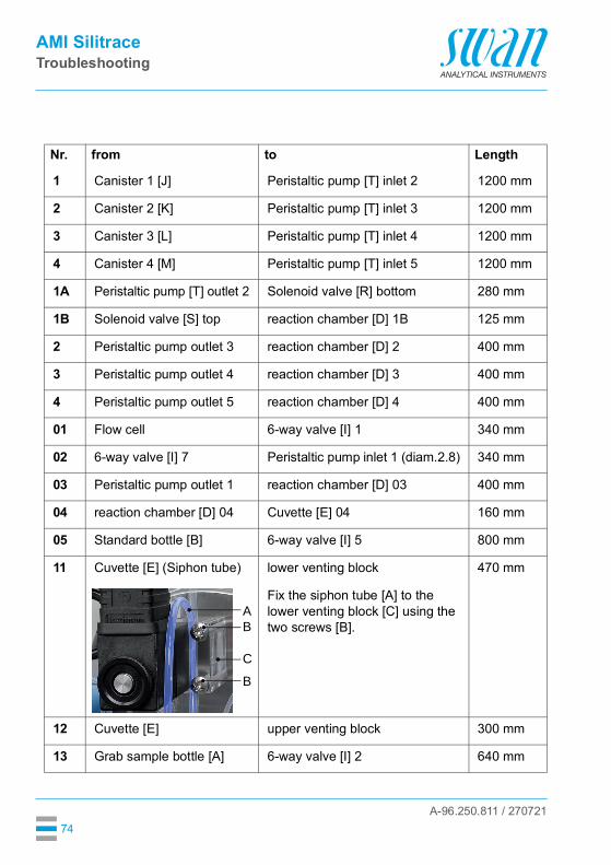
Nr. from to Length
1 Canister 1 [J] Peristaltic pump [T] inlet 2 1200 mm
2 Canister 2 [K] Peristaltic pump [T] inlet 3 1200 mm
3 Canister 3 [L] Peristaltic pump [T] inlet 4 1200 mm
4 Canister 4 [M] Peristaltic pump [T] inlet 5 1200 mm
1A Peristaltic pump [T] outlet 2 Solenoid valve [R] bottom 280 mm
1B Solenoid valve [S] top reaction chamber [D] 1B 125 mm
2 Peristaltic pump outlet 3 reaction chamber [D] 2 400 mm
3 Peristaltic pump outlet 4 reaction chamber [D] 3 400 mm
4 Peristaltic pump outlet 5 reaction chamber [D] 4 400 mm
01 Flow cell 6-way valve [I] 1 340 mm
02 6-way valve [I] 7 Peristaltic pump inlet 1 (diam.2.8) 340 mm
03 Peristaltic pump outlet 1 reaction chamber [D] 03 400 mm
04 reaction chamber [D] 04 Cuvette [E] 04 160 mm
05 Standard bottle [B] 6-way valve [I] 5 800 mm
11 Cuvette [E] (Siphon tube) lower venting block 470 mm
Fix the siphon tube [A] to the lower venting block [C] using the two screws [B].
12 Cuvette [E] upper venting block 300 mm
13 Grab sample bottle [A] 6-way valve [I] 2 640 mm
AB
C
B

A-96.250.811 / 270721
AMI SilitraceTroubleshooting
75
7.6. Cleaning the solenoid valveDisassemblethe solenoid
valve
The solenoid valve should be disassembled if it does not switch anymore or if it is clogged.
1 Switch off the instrument according to instructions in Stop of Op-eration for Maintenance, p. 52.
2 Loosen the nut (A).
3 Remove the solenoid coil (B) from the valve body (C).
4 Loosen the fixing screws of the valve body with a 2.5 mm Allen key (D).
A
B
C
D

A-96.250.811 / 270721
AMI SilitraceTroubleshooting
76
Assemble Assemble the solenoid valve in reverse order.
Note: The O-rings inside the valve body may stick on the flow cell and fall down if the valve body is removed.
5 Remove the valve body from the flow cell.
6 Remove the base plate (G) with a screw driver size 0 (F).
The membrane (H) is now visible.
7 Clean base plate (G) and mem-brane (H) with clean water.
E
F
G
H
A-96.250.811 / 270721
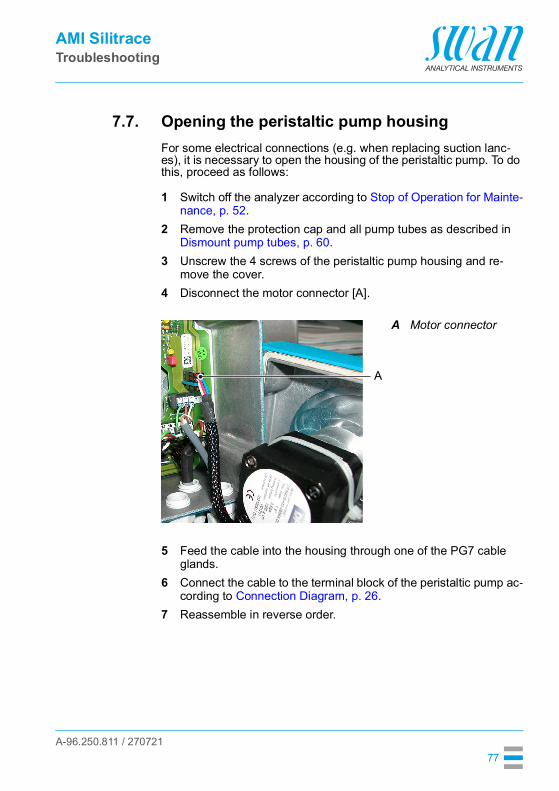
AMI SilitraceTroubleshooting
77
7.7. Opening the peristaltic pump housingFor some electrical connections (e.g. when replacing suction lanc-es), it is necessary to open the housing of the peristaltic pump. To do this, proceed as follows:
1 Switch off the analyzer according to Stop of Operation for Mainte-nance, p. 52.
2 Remove the protection cap and all pump tubes as described in Dismount pump tubes, p. 60.
3 Unscrew the 4 screws of the peristaltic pump housing and re-move the cover.
4 Disconnect the motor connector [A].
5 Feed the cable into the housing through one of the PG7 cable glands.
6 Connect the cable to the terminal block of the peristaltic pump ac-cording to Connection Diagram, p. 26.
7 Reassemble in reverse order.
A Motor connector
A

A-96.250.811 / 270721
AMI SilitraceTroubleshooting
78
7.8. Replacing Fuses
WARNING
External Voltage.External supplied devices connected to relay 1 or 2 or to the alarm relay can cause electrical shocks. Make sure that the devices connected to the following contacts
are disconnected from the power before resuming installation.– relay 1– relay 2– alarm relay
When a fuse has blown, find out the cause and fix it before replacing it with a new one.Use tweezers or needle-nosed pliers to remove the defective fuse. Use original fuses provided by SWAN only.
ABCDEFG
1.6 AT/250V Instrument power supply1.0 AT/250V Relay 11.0 AT/250V Relay 21.0 AT/250V Alarm relay1.0 AF/125V Signal output 21.0 AF/125V Signal output 11.0 AF/125V Signal output 3
A B C D E F G
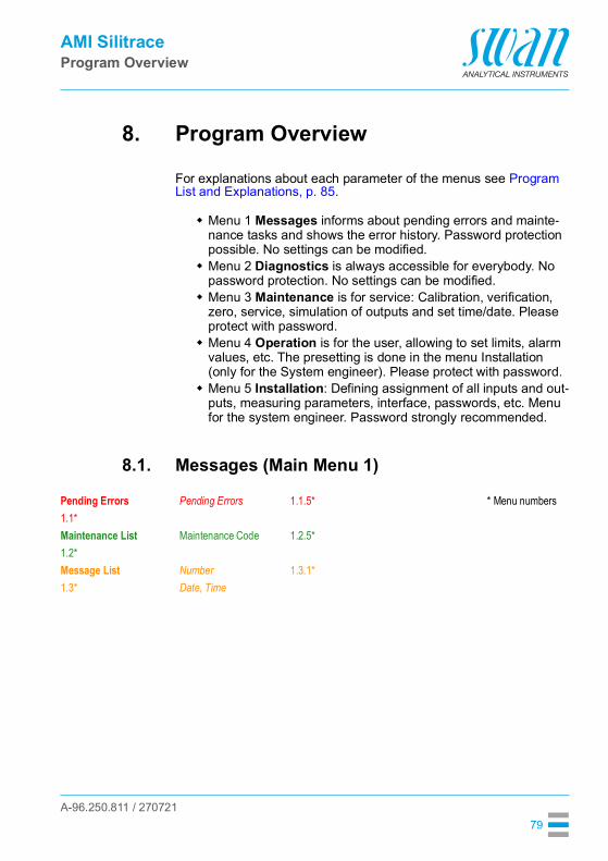
A-96.250.811 / 270721
AMI SilitraceProgram Overview
79
8. Program Overview
For explanations about each parameter of the menus see Program List and Explanations, p. 85.
Menu 1 Messages informs about pending errors and mainte-nance tasks and shows the error history. Password protection possible. No settings can be modified.
Menu 2 Diagnostics is always accessible for everybody. No password protection. No settings can be modified.
Menu 3 Maintenance is for service: Calibration, verification, zero, service, simulation of outputs and set time/date. Please protect with password.
Menu 4 Operation is for the user, allowing to set limits, alarm values, etc. The presetting is done in the menu Installation (only for the System engineer). Please protect with password.
Menu 5 Installation: Defining assignment of all inputs and out-puts, measuring parameters, interface, passwords, etc. Menu for the system engineer. Password strongly recommended.
8.1. Messages (Main Menu 1)
Pending Errors Pending Errors 1.1.5* * Menu numbers1.1*Maintenance List Maintenance Code 1.2.5*1.2*Message List Number 1.3.1*1.3* Date, Time

A-96.250.811 / 270721
AMI SilitraceProgram Overview
80
8.2. Diagnostics (Main Menu 2)Identification Designation AMI Silitrace * Menu numbers 2.1* Version V6.31-10/17
Peripherals PeriClip2.1.3* RoValve
SiliTraceFactory Test Instrument 2.1.3.1*2.1.4* MotherboardOperating Time Years / Days / Hours / Minutes / Seconds 2.1.4.1*2.1.5*
Sensors SilTrace Temp. 2.2* 2.2.1* PWM
Photometer Current value 2.2.1.3.1*2.2.1.3* (Raw value)
AbsorbanceFOME Mean
Case Temp. 2.2.2.1*2.2.2* State Machine 2.2.2.2*History Zero History Number 2.2.3.1.1*2.2.3* 2.2.3.1* Date, Time
ZeroCal. History Number 2.2.3.2.1*2.2.3.2* Date, Time
FactorVer. History Number 2.2.3.3.1*2.2.3.3* Date, Time
Meas. ValueReference valueDeviation
Grab Sample Number 2.2.3.4.1*Date, TimeSample IDSample

A-96.250.811 / 270721
AMI SilitraceProgram Overview
81
8.3. Maintenance (Main Menu 3)
Cycle diagnostics P2P period 2.2.4.1* * Menu numbers2.2.4* P2P counter
Pump speedAdjust cycle
Sample Sample ID 2.3.1* 2.3* Sample flow Sample flow 2.3.2.1*
2.3.2* (Raw value)I/O State Alarm Relay 2.4.1*2.4* Relay 1 and 2 2.4.2*
InputSignal Output 1 and 2
Interface Protocol 2.5.1* (only with RS4852.5* Baud rate interface)
Calibration3.1*Verification3.2*Zero3.3*Service Fill System Progress3.4* 3.4.1*
Prepare maintenance Progress3.4.2*Cuvette factor det. Progress3.4.3*
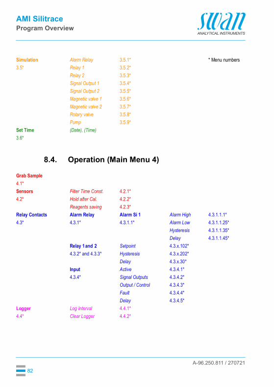
A-96.250.811 / 270721
AMI SilitraceProgram Overview
82
8.4. Operation (Main Menu 4)
Simulation Alarm Relay 3.5.1* * Menu numbers3.5* Relay 1 3.5.2*
Relay 2 3.5.3*Signal Output 1 3.5.4*Signal Output 2 3.5.5*Magnetic valve 1 3.5.6*Magnetic valve 2 3.5.7*Rotary valve 3.5.8*Pump 3.5.9*
Set Time (Date), (Time)3.6*
Grab Sample4.1*Sensors Filter Time Const. 4.2.1*4.2* Hold after Cal. 4.2.2*
Reagents saving 4.2.3*Relay Contacts Alarm Relay Alarm Si 1 Alarm High 4.3.1.1.1*4.3* 4.3.1* 4.3.1.1* Alarm Low 4.3.1.1.25*
Hysteresis 4.3.1.1.35*Delay 4.3.1.1.45*
Relay 1and 2 Setpoint 4.3.x.102*4.3.2* and 4.3.3* Hysteresis 4.3.x.202*
Delay 4.3.x.30*Input Active 4.3.4.1*4.3.4* Signal Outputs 4.3.4.2*
Output / Control 4.3.4.3*Fault 4.3.4.4*Delay 4.3.4.5*
Logger Log Interval 4.4.1*4.4* Clear Logger 4.4.2*

A-96.250.811 / 270721
AMI SilitraceProgram Overview
83
8.5. Installation (Main Menu 5)
Sensors Meas parameters Cal./Verif. Standard 5.1.1.1.1*5.1* 5.1.1 5.1.1.1* Parameters Start time
5.1.1.1.2* MondayTuesdayWednesdayThursdayFridaySaturdaySunday
Background Background 5.1.1.2.1*5.1.1.2*Auto-Zero Auto-Zero 5.1.1.3.1*5.1.1.3* Start time 5.1.1.3.2*Cuvette Factor5.1.1.4*
Multi-Channel Channels 5.1.2.1*Channel Selection 5.1.2.2*Switching time 5.1.2.3*
Signal Outputs Signal Output 1and 2 Parameter 5.2.1.1 - 5.2.2.1* 5.2* 5.2.1* - 5.2.2* Current Loop 5.2.1.2 - 5.2.2.2*
Function 5.2.1.3 - 5.2.2.3*Scaling Range Low 5.2.x.40.10/10*5.2.x.40 Range High 5.2.x.40.20/20*
Relay Contacts Alarm Relay Alarm Si 1 Alarm High 5.3.1.1.1* 5.3* 5.3.1* 5.3.1.1* Alarm Low 5.3.1.1.25
Hysteresis 5.3.1.1.35Delay 5.3.1.1.45
Sample Flow Flow Alarm 5.3.1.2.1*5.3.1.2* Alarm High 5.3.1.2.2*
Alarm Low 55.3.1.2.35*Case Temp. high 5.3.1.3*Case Temp. low 5.3.1.4*
Relay 1 and 2 Function 5.3.2.1–5.3.3.1*5.3.2* and 5.3.3* Parameter 5.3.2.20–5.3.3.20*

A-96.250.811 / 270721
AMI SilitraceProgram Overview
84
Setpoint 5.3.2.302–5.3.3.302*
* Menu numbers
Hysteresis 5.3.2.402–5.3.3.402*
Delay 5.3.2.50–5.3.3.50*
Input Active 5.3.4.1*5.3.4* Signal Outputs 5.3.4.2*
Output/Control 5.3.4.3*Fault 5.3.4.4*Delay 5.3.4.5*
Miscellaneous Language 5.4.1*5.4* Set defaults 5.4.2*
Load Firmware 5.4.3*Password Messages 5.4.4.1*5.4.4* Maintenance 5.4.4.2*
Operation 5.4.4.3*Installation 5.4.4.4*
Sample ID 5.4.5*Line break detection 5.4.6*Auto-Save 5.4.7*
Interface Protocol 5.5.1* (only with RS4855.5* Device Address 5.5.21* interface)
Baud Rate 5.5.31*Parity 5.5.41*
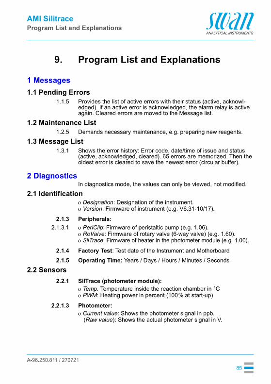
A-96.250.811 / 270721
AMI SilitraceProgram List and Explanations
85
9. Program List and Explanations
1 Messages1.1 Pending Errors
1.1.5 Provides the list of active errors with their status (active, acknowl-edged). If an active error is acknowledged, the alarm relay is active again. Cleared errors are moved to the Message list.
1.2 Maintenance List1.2.5 Demands necessary maintenance, e.g. preparing new reagents.
1.3 Message List1.3.1 Shows the error history: Error code, date/time of issue and status
(active, acknowledged, cleared). 65 errors are memorized. Then the oldest error is cleared to save the newest error (circular buffer).
2 DiagnosticsIn diagnostics mode, the values can only be viewed, not modified.
2.1 IdentificationDesignation: Designation of the instrument.Version: Firmware of instrument (e.g. V6.31-10/17).
2.1.3 Peripherals:2.1.3.1 PeriClip: Firmware of peristaltic pump (e.g. 1.06).
RoValve: Firmware of rotary valve (6-way valve) (e.g. 1.60).SilTrace: Firmware of heater in the photometer module (e.g. 1.00).
2.1.4 Factory Test: Test date of the Instrument and Motherboard2.1.5 Operating Time: Years / Days / Hours / Minutes / Seconds
2.2 Sensors2.2.1 SilTrace (photometer module):
Temp. Temperature inside the reaction chamber in °CPWM: Heating power in percent (100% at start-up)
2.2.1.3 Photometer:Current value: Shows the photometer signal in ppb.
(Raw value): Shows the actual photometer signal in V.

A-96.250.811 / 270721
AMI SilitraceProgram List and Explanations
86
FOME Mean: Raw signal in V, measured during T2 (pump stopped) to calculate the concentration.
2.2.2 Miscellaneous:Case Temp: Shows the current temperature in °C inside the
transmitter.State Machine: Shows the current process of the instrument.
Absorbance: A = -log10 zeroFOME mean
WARMUP The instrument is heating up after start-up or recov-ery from a fatal error.
WAITRDY The instrument has a fatal error i.e. pump and heater off. The instrument will stay in this state until the fatal error is acknowledged or self cleared.
WAITFLOW The instrument has a sample flow low (E010) alarm. In this case, the pump stops but the heater stays on. It remains in this state until the sample flow is re-established.
FLUSH Before and after performing a zero, a calibration, a verification or a grab sample measurement and after recovering from an alarm, the instrument is flushing.
Measurement cycleFIND PEAK Step 1 of measurement (pump on):
The instrument is in measuring mode, waiting for the peak.
WAIT T1 Step 2 of measurement (pump on):The instrument is in measuring mode, peak found and filling the photometer de-aeration tube and the siphon tube. See Fluidic, p. 12.
WAIT T2 Step 3 of measurement (pump off):The instrument is in measuring mode, waiting for stabilization. FOME mean is recorded. After this state, the instrument goes back to FIND PEAK.
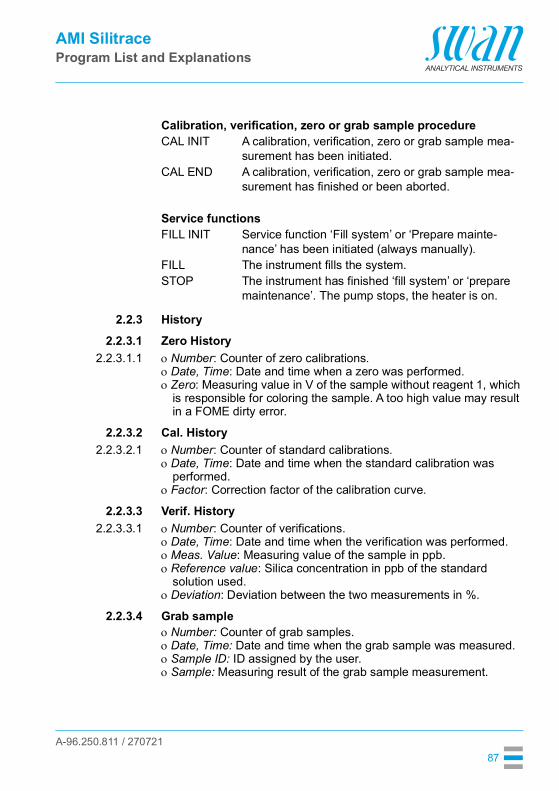
A-96.250.811 / 270721
AMI SilitraceProgram List and Explanations
87
2.2.3 History2.2.3.1 Zero History
2.2.3.1.1 Number: Counter of zero calibrations.Date, Time: Date and time when a zero was performed.Zero: Measuring value in V of the sample without reagent 1, which
is responsible for coloring the sample. A too high value may result in a FOME dirty error.
2.2.3.2 Cal. History2.2.3.2.1 Number: Counter of standard calibrations.
Date, Time: Date and time when the standard calibration was performed.
Factor: Correction factor of the calibration curve.
2.2.3.3 Verif. History2.2.3.3.1 Number: Counter of verifications.
Date, Time: Date and time when the verification was performed.Meas. Value: Measuring value of the sample in ppb.Reference value: Silica concentration in ppb of the standard
solution used.Deviation: Deviation between the two measurements in %.
2.2.3.4 Grab sampleNumber: Counter of grab samples.Date, Time: Date and time when the grab sample was measured.Sample ID: ID assigned by the user.Sample: Measuring result of the grab sample measurement.
Calibration, verification, zero or grab sample procedureCAL INIT A calibration, verification, zero or grab sample mea-
surement has been initiated.CAL END A calibration, verification, zero or grab sample mea-
surement has finished or been aborted.
Service functionsFILL INIT Service function ‘Fill system’ or ‘Prepare mainte-
nance’ has been initiated (always manually).FILL The instrument fills the system.STOP The instrument has finished ‘fill system’ or ‘prepare
maintenance’. The pump stops, the heater is on.
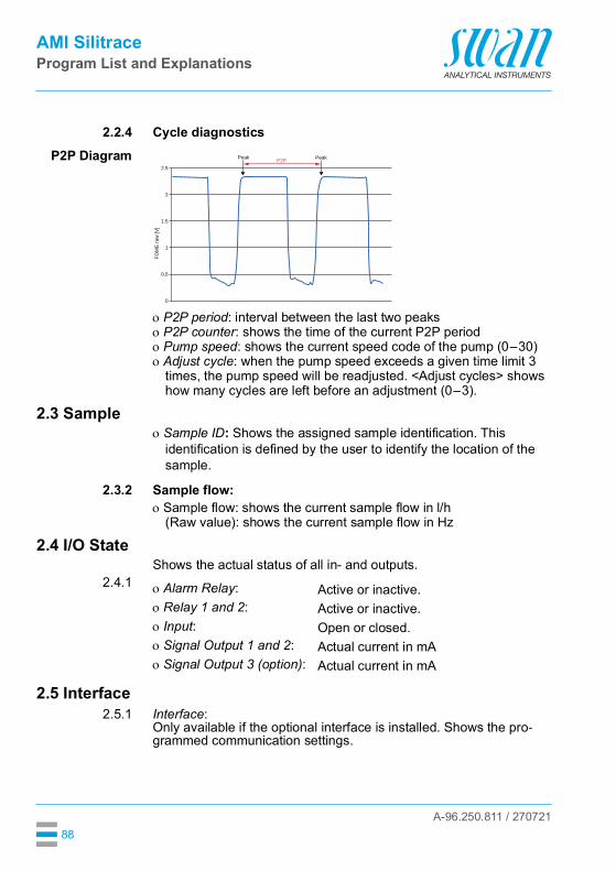
A-96.250.811 / 270721
AMI SilitraceProgram List and Explanations
88
2.2.4 Cycle diagnosticsP2P Diagram
P2P period: interval between the last two peaksP2P counter: shows the time of the current P2P periodPump speed: shows the current speed code of the pump (0–30)Adjust cycle: when the pump speed exceeds a given time limit 3
times, the pump speed will be readjusted. <Adjust cycles> shows how many cycles are left before an adjustment (0–3).
2.3 SampleSample ID: Shows the assigned sample identification. This
identification is defined by the user to identify the location of the sample.
2.3.2 Sample flow:Sample flow: shows the current sample flow in l/h
(Raw value): shows the current sample flow in Hz
2.4 I/O StateShows the actual status of all in- and outputs.
2.4.1
2.5 Interface2.5.1 Interface:
Only available if the optional interface is installed. Shows the pro-grammed communication settings.
0
0.5
1
FOM
E ra
w [V
]
1.5
2
2.5
Peak P2P Peak
Alarm Relay: Active or inactive.Relay 1 and 2: Active or inactive.Input: Open or closed.Signal Output 1 and 2: Actual current in mASignal Output 3 (option): Actual current in mA
A-96.250.811 / 270721
AMI SilitraceProgram List and Explanations
89
3 Maintenance3.1 Calibration
3.1.5 During calibration, a solution of known silica concentration (standard) is measured and the measuring value is compared with the refer-ence value of the standard (set in 5.1.1.1, p. 92). The instrument then sets the calibration factor to adjust the photometer sensitivity.It is recommended to perform a calibration: at first start-up after replacing the pump tubes after replacing the cuvette
All calibrations are saved in the calibration history.
3.2 Verification3.2.5 During verification, a solution of known silica concentration (stan-
dard) is measured and the mesuring value is compared with the ref-erence value of the standard. The deviation is expressed in percent. Unlike a calibration, a verification does not change the calibration factor.It is recommended to check the performance of the system by an au-tomatic weekly verification (default setting).All verifications are saved in the Verification History.
3.3 Zero3.3.5 To determine the electronic offset and light intensity of the photome-
ter, the sample is measured without adding the color forming reagent 1.It is recommended to program an automatic daily zero calibration (default setting).
3.4 Service3.4.1 Fill system
3.4.1.5 Activates the reagent pump and fills all tubes from the container to the cuvette outlet.
3.4.2 Prepare MaintenanceAll tubes are rinsed and emptied when starting this function.
Note: Follow the instructions on the screen carefully, otherwise the reagents in the canisters will be polluted with already mixed reagents.

A-96.250.811 / 270721
AMI SilitraceProgram List and Explanations
90
3.4.3 Cuvette factor determinationThe cuvette factor is unique for each combination of photometer and cuvette. It is set at the factory and stored in a protected memory area (i. e. it is not deleted by a complete reset or an upgrade of the firm-ware).If the cuvette or photometer is replaced, the cuvette factor must be determined again.
3.5 SimulationTo simulate a value or a relay state, select the alarm relay relay 1 and 2 signal output 1 and 2
with the [ ] or [ ] key.Press the [Enter] key.Change the value or state of the selected item with the [ ] or [ ] key.
The value is simulated by the relay/signal output.
* Magnetic valve 1: Zero calibration valveMagnetic valve 2: Channel selector valve (AMI Silitrace Dual-Stream)
At the absence of any key activities, the instrument will switch back to normal mode after 20 min. If you quit the menu, all simulated val-ues will be reset.
3.6 Set TimeAdjust date and time.
3.5.13.5.23.5.33.5.43.5.53.5.63.5.73.5.83.5.9
Alarm Relay:Relay 1:Relay 2:Signal Output 1:Signal Output 2:Magnetic valve 1*:Magnetic valve 2*:Rotary valve:Pump:
Active or inactive.Active or inactive.Active or inactiveActual current in mAActual current in mAActive or inactiveActive or inactivePosition 1 to 6Active or inactive

A-96.250.811 / 270721
AMI SilitraceProgram List and Explanations
91
4 Operation4.1 Grab Sample
4.1.5 Starts a grab sample measurement. See Grab Sample Measure-ment, p. 50.
4.2 Sensors4.2.1 Filter Time Constant: Used to damp noisy signals. The higher the fil-
ter time constant, the slower the system reacts to changes of the measured value.Range: 5–300 Sec
4.2.2 Hold after Cal: Delay permitting the instrument to stabilize again after calibration. During calibration- plus hold-time, the signal outputs are frozen (held on last valid value), alarm values, limits are not active.Range: 0–6‘000 Sec
4.2.3 Reagents saving: Increases the duration of the T2 state (pump off) to save reagents.Range: No, Minimum, Medium, MaximumOn a single-channel instrument, the reagent saving mode has the following effect on the measuring cycle and the reagent lifetime:
On a multi-channel instrument, the reagent saving effect depends on the switching time (see 5.1.2.3, p. 95). The faster the channels are switched, the smaller the reagent saving effect is. The following table shows the reagent saving effect for different switching times if <Reagents saving> is set to <Maximum>. <Medi-um> and <Minimum> correspond to 66% and 33% of the reagent sav-ing effect.
Option Measuring cycle Reagent lifetimeNo 2.8 min approx. 28 dMinimum 5.3 min approx. 50 dMedium 7.8 min approx. 75 dMaximum 10.3 min approx. 100 d
Switching time Measuring cycle Reagent lifetime15 min 3.0 min approx. 28 d20 min 3.8 min approx. 35 d30 min 5.5 min approx. 50 d40 min 7.2 min approx. 70 d50 min 8.8 min approx. 85 d60 min 10.3 min approx. 100 d
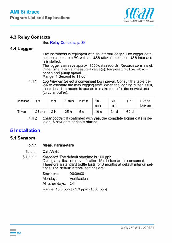
A-96.250.811 / 270721
AMI SilitraceProgram List and Explanations
92
4.3 Relay ContactsSee Relay Contacts, p. 28
4.4 LoggerThe instrument is equipped with an internal logger. The logger data can be copied to a PC with an USB stick if the option USB interface is installed.The logger can save approx. 1500 data records. Records consists of: Date, time, alarms, measured value(s), temperature, flow, absor-bance and pump speed.Range: 1 Second to 1 hour
4.4.1 Log Interval: Select a convenient log interval. Consult the table be-low to estimate the max logging time. When the logging buffer is full, the oldest data record is erased to make room for the newest one (circular buffer).
4.4.2 Clear Logger: If confirmed with yes, the complete logger data is de-leted. A new data series is started.
5 Installation5.1 Sensors
5.1.1 Meas. Parameters5.1.1.1 Cal./Verif.
5.1.1.1.1 Standard: The default standard is 100 ppb.During a calibration or verification 15 ml standard is consumed. Therefore a standard bottle lasts for 3 months at default interval set-tings. The default interval settings are:
Range: 10.0 ppb to 1.0 ppm (1000 ppb)
Interval 1 s 5 s 1 min 5 min 10 min
30 min
1 h Event Driven
Time 25 min 2 h 25 h 5 d 10 d 31 d 62 d
Start time: 06:00:00Monday: VerificationAll other days: Off

A-96.250.811 / 270721
AMI SilitraceProgram List and Explanations
93
5.1.1.1.2 Parameters5.1.1.1.2.1 Start time: Program the daily start time of a verification or calibration.
Default setting is 06:00:005.1.1.1.2.2 Monday: Program a verification, a calibration or Off for this day. A veri-
fication or calibration will be started at the programed <start time>.5.1.1.1.2.3 Tuesday: Same as Monday.5.1.1.1.2.4 Wednesday: Same as Monday.5.1.1.1.2.5 Thursday: Same as Monday.5.1.1.1.2.6 Friday: Same as Monday.5.1.1.1.2.7 Saturday: Same as Monday.5.1.1.1.2.8 Sunday: Same as Monday.
Note: If there is an overlap between a programmed zero calibration and a programmed calibration/verification, the zero calibration is prioritized and the calibration/verification is skipped.
5.1.1.2 Reag, Background5.1.1.2.1 Reag. Background: Enter the known basic pollution of the reagents.
The entered value will be subtracted form the measuring value.5.1.1.3 Auto-Zero
5.1.1.3.1 Auto-Zero: Activate or deactivate automatic daily zero calibration.Note: The zero calibration is essential for correct measurement. Swan therefore strongly recommends to have the Auto-Zero option activated. If this option is deactivated, the zero calibration must be started manually or via fieldbus at regular intervals.
5.1.1.3.2 Start time: Enter the start time of an auto zero measurement.5.1.1.4 Cuvette Factor: Shows the current cuvette factor.
5.1.2 Multi-Channel5.1.2.1 Channels: If a Sample Sequencer is connected, set the number of
active channels (up to 6). Otherwise, set this parameter to 1 or 2 ac-cording to the instrument variant.
5.1.2.2 Channel Selection: The following three operating modes can be set: Internal Fieldbus External

A-96.250.811 / 270721
AMI SilitraceProgram List and Explanations
94
Mode Internal In the Mode Internal, the AMI Silitrace works as a master.AMI Silitrace Dual-StreamThe instrument automatically switches between channel 1 and 2.Sample SequencerThe AMI Silitrace sequentially measures each single sample stream of the Sample Sequencer. Via an external PLC it can be defined which sample streams should not be measured. In the example be-low, only the sample streams 2, 4 and 6 are measured, whereas the samples streams 1, 3 and 5 are switched off. Sample streams which are switched off are marked with an “x” behind the measuring value on the AMI Silitrace display.
Mode Fieldbus The AMI Silitrace is controlled via fieldbus.
CH1
SEQUENCER
Proc
esso
r
CH2CH3CH4CH5
6 In
puts
from
PLC
1 m
A si
nk, 5
V o
pen
CH6
GND
9
1011121314
15
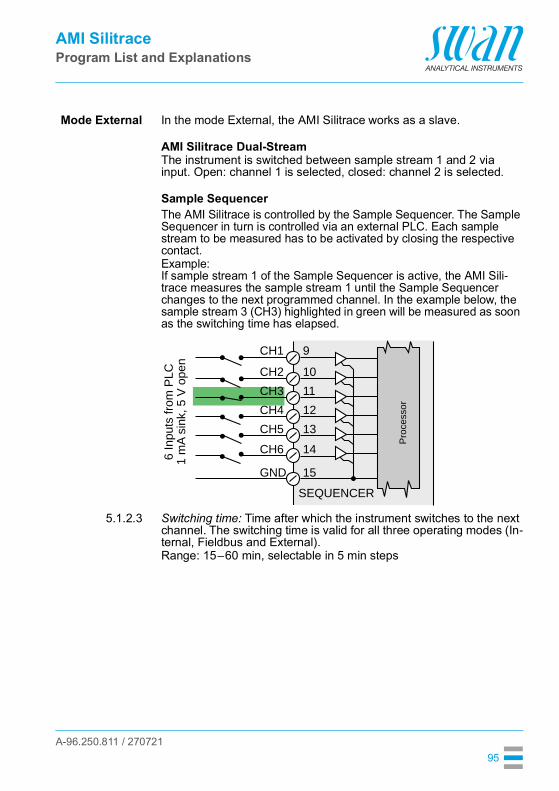
A-96.250.811 / 270721
AMI SilitraceProgram List and Explanations
95
Mode External In the mode External, the AMI Silitrace works as a slave.
AMI Silitrace Dual-StreamThe instrument is switched between sample stream 1 and 2 via input. Open: channel 1 is selected, closed: channel 2 is selected.
Sample SequencerThe AMI Silitrace is controlled by the Sample Sequencer. The Sample Sequencer in turn is controlled via an external PLC. Each sample stream to be measured has to be activated by closing the respective contact.Example:If sample stream 1 of the Sample Sequencer is active, the AMI Sili-trace measures the sample stream 1 until the Sample Sequencer changes to the next programmed channel. In the example below, the sample stream 3 (CH3) highlighted in green will be measured as soon as the switching time has elapsed.
5.1.2.3 Switching time: Time after which the instrument switches to the next channel. The switching time is valid for all three operating modes (In-ternal, Fieldbus and External).Range: 15–60 min, selectable in 5 min steps
CH1
SEQUENCER
Proc
esso
r
CH2CH3CH4CH5
6 In
puts
from
PLC
CH6
GND
9
1011121314
15
1 m
A si
nk, 5
V o
pen
A-96.250.811 / 270721
AMI SilitraceProgram List and Explanations
96
5.2 Signal OutputsNote: The navigation in the menu <Signal Output 1> and <Signal Output 2> is identical. For reason of simplicity only the menu numbers of Signal Output 1 are used in the following.
5.2.1 and 5.2.2 Signal Output 1 and 2: Assign process value, the current loop range and a function to each signal output.
5.2.1.1 Parameter: Assign one of the process values to the signal output.Available values: Sample Flow Si1 Si2 (AMI Silitrace Dual-Stream)
5.2.1.2 Current Loop: Select the current range of the signal output. Make sure the connected device works with the same current range.Available ranges: 0–20 mA or 4–20 mA
5.2.1.3 Function: Define if the signal output is used to transmit a process val-ue or to drive a control unit. Available functions are: Linear, bilinear or logarithmic for process values.
See As process values, p. 97 Control upwards or control downwards for controllers.
See As control output, p. 99
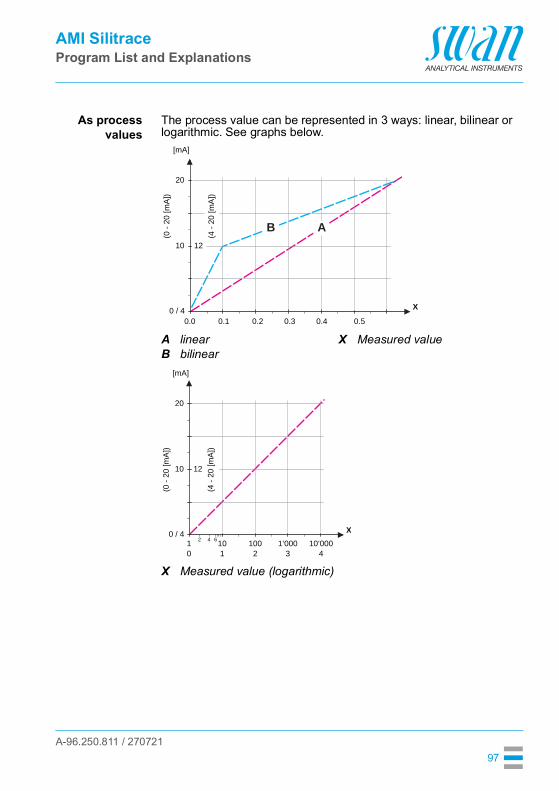
A-96.250.811 / 270721
AMI SilitraceProgram List and Explanations
97
As processvalues
The process value can be represented in 3 ways: linear, bilinear or logarithmic. See graphs below.
AB
linearbilinear
X Measured value
X Measured value (logarithmic)
20
0.0 0.1 0.2 0.3 0.4 0.5
10 12
(0 -
20 [m
A])
0 / 4
(4 -
20 [m
A])
[mA]
X
AB
20
10 1 2 3 4
10 100 1’000 10’000
10 12
(0 -
20 [m
A])
0 / 442 6
(4 -
20 [m
A])
[mA]
X
A-96.250.811 / 270721
AMI SilitraceProgram List and Explanations
98
5.2.1.40 Scaling: Enter beginning and end point (Range low & high) of the linear or logarithmic scale. In addition, the midpoint for the bilinear scale.
Parameter Sample flow:5.2.1.40.10 Range low: 0–50 l/h5.2.1.40.20 Range high: 0–50 l/h
Parameter Si1:5.2.1.40.11 Range low: 0.0 ppb to 1.00 ppm5.2.1.40.21 Range high: 0.0 ppb to 1.00 ppm
Parameter Si2:5.2.1.40.12 Range low: 0.0 ppb to 1.00 ppm5.2.1.40.22 Range high: 0.0 ppb to 1.00 ppm

A-96.250.811 / 270721
AMI SilitraceProgram List and Explanations
99
As controloutput
Signal outputs can be used for driving control units. We distinguish different kinds of controls: P-controller: The controller action is proportional to the devia-
tion from the setpoint. The controller is characterized by the P-Band. In the steady-state, the setpoint will never be reached. The deviation is called steady-state error.Parameters: setpoint, P-Band
PI-controller: The combination of a P-controller with anI-controller will minimize the steady-state error. If the reset time is set to zero, the I-controller is switched off.Parameters: setpoint, P-Band, reset time.
PD-controller: The combination of a P-controller with a D-controller will minimize the response time to a fast change of the process value. If the derivative time is set to zero, the D-controller is switched off.Parameters: setpoint, P-Band, derivative time.
PID-controller: The combination of a P-, an I - and a D-control-ler allows a proper control of the process.Parameters: setpoint, P-Band, reset time, derivative time.
Ziegler-Nichols method for the optimization of a PID controller:Parameters: Setpoint, P-Band, Reset time, Derivative time
The point of intersection of the tangent with the respective axis will result in the parameters a and L.Consult the manual of the control unit for connecting and program-ming details. Choose control upwards or downwards.
ABX
Response to maximum control outputTangent on the inflection pointTime
XpTnTv
= 1.2/a= 2L= L/2
X
Y
B A
L
a
A-96.250.811 / 270721
AMI SilitraceProgram List and Explanations
100
If Control upwards or Control downwards is active:5.2.1.43 Control Parameters
5.2.1.43.10 Setpoint: User-defined process value (Measured value or flow)5.2.1.43.20 P-Band: Range below (upwards control) or above (downwards con-
trol) the set-point, within the dosing intensity is reduced from 100% to 0% to reach the set-point without overshooting.
5.2.1.43 Control Parameters: if Parameters = Sample flow5.2.1.43.10 Setpoint: 0–50 l/h5.2.1.43.20 P-Band: 0–50 l/h
5.2.1.43 Control Parameters: if Parameters = Si1 or Si25.2.1.43.12 Setpoint: 0.0 ppb to 1.00 ppm5.2.1.43.22 P-Band: 0.0 ppb to 1.00 ppm5.2.1.43.3 Reset time: The reset time is the time till the step response of a sin-
gle I-controller will reach the same value as it will be suddenly reached by a P-controller.Range: 0–9’000 sec
5.2.1.43.4 Derivative time: The derivative time is the time till the ramp response of a single P-controller will reach the same value as it will be sudden-ly reached by a D-controller.Range: 0–9’000 sec
5.2.1.43.5 Control timeout: If a controller action (dosing intensity) is constantly over 90% during a defined period of time and the process value does not come closer to the setpoint, the dosing process will be stopped for safety reasons.Range: 0–720 min
5.2.4 Signal Sequencer: Only visible if a Sample Sequencer is connected.Assign process value, the current loop range and a function to the signal output.
5.2.4.1 Parameter: Only the parameter “Si Sequencer” is available.5.2.4.2 Current Loop: Select the current range of the signal output. Make
sure the connected device works with the same current range.Available ranges: 0–20 mA or 4–20 mA
5.2.4.3 Scaling: Define the scaling of the signal output used to transmit a process value. Available functions are:Linear, bilinear or logarithmic for process values.See As process values, p. 97.

A-96.250.811 / 270721
AMI SilitraceProgram List and Explanations
101
5.3 Relay Contacts5.3.1 Alarm Relay: The alarm relay is used as cumulative error indicator.
Under normal operating conditions the contact is active.The contact is inactive at: Power loss Detection of system faults like defective sensors or electronic
parts High case temperature Process values out of programmed ranges.
Program alarm levels for the following parameters: Si1 Si2 (multi-channel instruments) Sample Flow Case Temperature high Case Temperature low
5.3.1.1/5.3.1.2 Alarm Si1 and Si25.3.1.x.1 Alarm High: If the measured value rises above the alarm high value,
the alarm relay is activated and E001/E003, is displayed in the mes-sage list.Range: 0.0 ppb to 1.00 ppm
5.3.1.x.22 Alarm Low: If the measured value falls below the alarm low value, the alarm relay is activated and E002/E004 is displayed in the mes-sage list.Range: 0.0 ppb to 1.00 ppm
5.3.1.x.32 Hysteresis: Within the hyst. range, the relay does not switch. This prevents damage of relays contacts when the measured value fluctu-ates around the alarm value.Range: 0.0 ppb to 1.00 ppm
5.3.1.x.42 Delay: Duration, the activation of the alarm relay is retarded after the measuring value has risen above/fallen below the programmed alarm. Range: 0–28‘800 Sec
5.3.1.32 Sample Flow: Define at which sample flow a flow alarm should be issued.
5.3.1.32.1 Flow Alarm: Program if the alarm relay should be activated if there is a flow alarm. Choose between yes or no. The flow alarm will always be indicated in the display, pending error list, saved in the message list and the logger.Available values: Yes or no
Note: Sufficient flow is essential for a correct measurement.We recommend to program yes.

A-96.250.811 / 270721
AMI SilitraceProgram List and Explanations
102
5.3.1.32.2 Alarm High: If the measuring values rises above the programmed value E009 will be issued.Range: 0–50 l/h
5.3.1.32.32 Alarm Low: If the measuring values falls below the programmed val-ue E010 will be issued.Range: 0–50 l/h
5.3.1.42 Case Temp. high: Set the alarm high value for temperature of electronics housing. If the value rises above the programmed value E013 is issued.Range: 30–75 °C
5.3.1.5 Case Temp. low: Set the alarm low value for temperature of electronics housing. If the value falls below the programmed value E014 is issued.Range: -10–20 °C
5.3.2 and 5.3.3 Relay 1 and 2: The contacts can be set as normally open or normal-ly closed with a jumper. See Relay 1 and 2, p. 29.The function of relay contacts 1 or 2 are defined by the user
Note: The navigation in the menu <Relay 1> and <Relay 2> is identical. For reason of simplicity only the menu numbers of Relay 1 are used in the following.
1 First select the functions as:- Limit upper/lower, - Control upwards/downwards, - Timer - Fieldbus- Channel Selection (AMI Silitrace Dual-Stream)
2 Then enter the necessary data depending on the selected func-tion.
When the relays are used as upper or lower limit switches, program the following:
5.3.2.20 Parameter: select a process value: Sample flow Si1 Si2 (AMI Silitrace Dual-Stream)
5.3.2.300 Setpoint: If the measured value rises above respectively falls below the set-point, the relay is activated.Range: 0.0 ppb to 1.00 ppm
5.3.2.400 Hysteresis: within the hysteresis range, the relay does not switch. This prevents damage of relay contacts when the measured value fluctuates around the alarm value.Range: 0.0 ppb to 1.00 ppm
5.3.2.1 Function = Limit upper/lower:

A-96.250.811 / 270721
AMI SilitraceProgram List and Explanations
103
5.3.2.50 Delay: Duration, the activation of the alarm relay is retarded after the measuring value has risen above/fallen below the programmed alarm.Range. 0–600 sec
The relays may be used to drive control units such as solenoid valves, membrane dosing pumps or motor valves. When driving a motor valve both relays are needed, relay 1 to open and relay 2 to close the valve.
5.3.2.22 Parameter: Choose on of the following process values. Sample flow Si1 Si2 (AMI Silitrace Dual-Stream)
5.3.2.32 Settings: Choose the respective actuator: Time proportional Frequency Motor valve
Examples of metering devices that are driven time proportional are solenoid valves, peristaltic pumps.Dosing is controlled by the operating time.
5.3.2.32.20 Cycle time: duration of one control cycle (on/off change).Range: 0–600 sec.
5.3.2.32.30 Response time: Minimal time the metering device needs to react. Range: 0–240 sec.
5.3.2.32.4 Control ParametersRange for each Parameter same as 5.2.1.43, p. 100
Examples of metering devices that are pulse frequency driven are the classic membrane pumps with a potential free triggering input. Dosing is controlled by the repetition speed of dosing shots.
5.3.2.32.21 Pulse frequency: Max. pulses per minute the device is able to re-spond to. Range: 20–300/min.
5.3.2.32.31 Control ParametersRange for each Parameter same as 5.2.1.43, p. 100
Dosing is controlled by the position of a motor driven mixing valve.5.3.2.32.22 Run time: Time needed to open a completely closed valve
Range: 5–300 sec.
5.3.2.1 Function = Control upwards/downwards:
5.3.2.32.1 Actuator = Time proportional
5.3.2.32.1 Actuator = Frequency
5.3.2.32.1 Actuator = Motor valve

A-96.250.811 / 270721
AMI SilitraceProgram List and Explanations
104
5.3.2.32.32 Neutral zone: Minimal response time in % of the runtime. If the re-quested dosing output is smaller than the response time, no change will take place.Range: 1–20%
5.3.2.32.4 Control ParametersRange for each Parameter same as 5.2.1.43, p. 100
The relay will be activated repetitively depending on the programmed time scheme.
5.3.2.24 Mode: Operating mode (interval, daily, weekly)
5.3.2.340 Interval: The interval can be programmed within a rangeof 1–1’440 min.
5.3.2.44 Run Time: Enter the time the relay stays activated.Range: 5–32’400 sec.
5.3.2.54 Delay: during run time plus the delay time the signal and control out-puts are held in the operating mode programmed below.Range: 0–6’000 sec.
5.3.2.6 Signal Outputs: Select operating mode of the signal output:
5.3.2.7 Output/Control: Select operating mode of the controller output:
The relay contact can be activated daily, at any time of a day.5.3.2.341 Start time: to set the start time proceed as follows:
1 Press [Enter], to set the hours.2 Set the hour with the [ ] or [ ] keys.3 Press [Enter], to set the minutes.
5.3.2.1 Function = Timer:
5.3.2.24 Interval
Cont.: Signal outputs continue to issue the measured value.Hold: Signal outputs hold the last valid measured value.
Measurement is interrupted. Errors, except fatal errors, are not issued.
Off: Signal outputs are switched off (set to 0 or 4 mA).Errors, except fatal errors, are not issued.
Cont.: Controller continues normally.Hold: Controller continues based on the last valid value.Off: Controller is switched off.
5.3.2.24 daily

A-96.250.811 / 270721
AMI SilitraceProgram List and Explanations
105
4 Set the minutes with the [ ] or [ ] keys.5 Press [Enter], to set the seconds.6 Set the seconds with the [ ] or [ ] keys.
Range: 00:00:00–23:59:595.3.2.44 Run Time: see Interval5.3.2.54 Delay: see Interval5.3.2.6 Signal Outputs: see Interval5.3.2.7 Output/Control: see Interval
The relay contact can be activated at one or several days, of a week. The daily starting time is valid for all days.
5.3.2.342 Calendar:5.3.2.342.1 Start time: The programmed start time is valid for each of the pro-
grammed days. To set the start time see 5.3.2.341, p. 104.Range: 00:00:00–23:59:59
5.3.2.342.2 Monday: Possible settings, on or offto
5.3.2.342.8 Sunday: Possible settings, on or off5.3.2.44 Run Time: see Interval5.3.2.54 Delay: see Interval5.3.2.6 Signal Outputs: see Interval5.3.2.7 Output/Control: see Interval
The relay will be switched via the Profibus input. No further parame-ters are needed.
AMI Silitrace Dual-Stream:Relay 2 can be used to indicate which channel is selected. No further parameters are needed.
5.3.2.24 weekly
5.3.2.1 Function = Fieldbus:
5.3.2.1 Function = Channel Selection:
Relay 2 inactive Channel 1 is selectedRelay 2 active: Channel 2 is selected
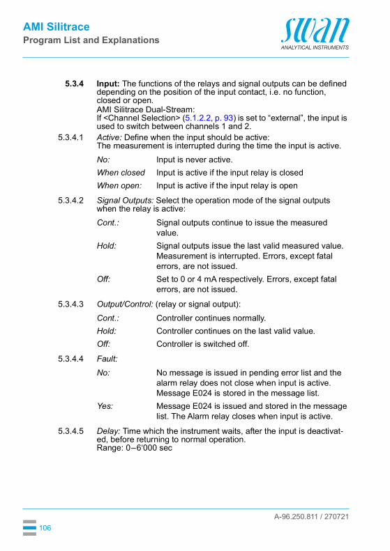
A-96.250.811 / 270721
AMI SilitraceProgram List and Explanations
106
5.3.4 Input: The functions of the relays and signal outputs can be defined depending on the position of the input contact, i.e. no function, closed or open.AMI Silitrace Dual-Stream:If <Channel Selection> (5.1.2.2, p. 93) is set to “external”, the input is used to switch between channels 1 and 2.
5.3.4.1 Active: Define when the input should be active:The measurement is interrupted during the time the input is active.
5.3.4.2 Signal Outputs: Select the operation mode of the signal outputs when the relay is active:
5.3.4.3 Output/Control: (relay or signal output):
5.3.4.4 Fault:
5.3.4.5 Delay: Time which the instrument waits, after the input is deactivat-ed, before returning to normal operation.Range: 0–6‘000 sec
No: Input is never active.When closed Input is active if the input relay is closedWhen open: Input is active if the input relay is open
Cont.: Signal outputs continue to issue the measured value.
Hold: Signal outputs issue the last valid measured value.Measurement is interrupted. Errors, except fatal errors, are not issued.
Off: Set to 0 or 4 mA respectively. Errors, except fatal errors, are not issued.
Cont.: Controller continues normally.Hold: Controller continues on the last valid value.Off: Controller is switched off.
No: No message is issued in pending error list and the alarm relay does not close when input is active. Message E024 is stored in the message list.
Yes: Message E024 is issued and stored in the message list. The Alarm relay closes when input is active.
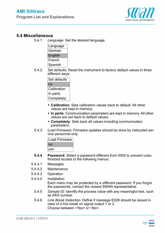
A-96.250.811 / 270721
AMI SilitraceProgram List and Explanations
107
5.4 Miscellaneous5.4.1 Language: Set the desired language.
5.4.2 Set defaults: Reset the instrument to factory default values in three different ways:
Calibration: Sets calibration values back to default. All other values are kept in memory.
In parts: Communication parameters are kept in memory. All other values are set back to default values.
Completely: Sets back all values including communication parameters.
5.4.3 Load Firmware: Firmware updates should be done by instructed ser-vice personnel only.
5.4.4 Password: Select a password different from 0000 to prevent unau-thorized access to the following menus:
5.4.4.1 Messages5.4.4.2 Maintenance5.4.4.3 Operation5.4.4.4 Installation
Each menu may be protected by a different password. If you forgot the passwords, contact the closest SWAN representative.
5.4.5 Sample ID: Identify the process value with any meaningful text, such as KKS number.
5.4.6 Line Break Detection: Define if message E028 should be issued in case of a line break on signal output 1 or 2.Choose between <Yes> or <No>.
LanguageGermanEnglishFrenchSpanish
Set defaultsnoCalibrationIn partsCompletely
Load Firmwarenoyes

A-96.250.811 / 270721
AMI SilitraceProgram List and Explanations
108
5.4.7 Auto-Save: The result of a manually started procedure (e.g. grab sample measurement) is displayed on the screen for 20 minutes. If no key is pressed during this time, the instrument automatically re-turns to the main screen.The Auto-Save setting determines whether the result is automatically saved or discarded after these 20 minutes.Choose between <Yes> or <No>.
The setting applies to the following procedures: grab sample measurement (zero) calibration verification cuvette factor determination
5.5 InterfaceSelect one of the following communication protocols. Depending on your selection, different parameters must be defined.
5.5.1 Protocol: Profibus5.5.20 Device address: Range: 0–1265.5.30 ID-Nr.: Range: Analyzer; Manufacturer; Multivariable5.5.40 Local operation: Range: Enabled, Disabled
5.5.1 Protocol: Modbus RTU5.5.21 Device address: Range: 0–1265.5.31 Baud Rate: Range: 1200–115 200 Baud5.5.41 Parity: Range: none, even, odd
5.5.1 Protocol: USB stick:Only visible if an USB interface is installed. No further settings are possible.
5.5.1 Protocol: HART5.5.24 Device address: Range: 0–63
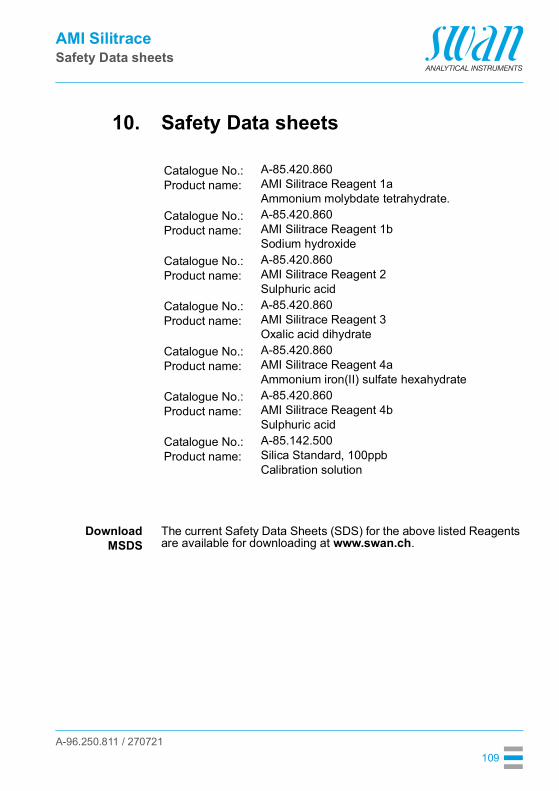
A-96.250.811 / 270721
AMI SilitraceSafety Data sheets
109
10. Safety Data sheets
DownloadMSDS
The current Safety Data Sheets (SDS) for the above listed Reagents are available for downloading at www.swan.ch.
Catalogue No.:Product name:
A-85.420.860AMI Silitrace Reagent 1aAmmonium molybdate tetrahydrate.
Catalogue No.:Product name:
A-85.420.860AMI Silitrace Reagent 1bSodium hydroxide
Catalogue No.:Product name:
A-85.420.860AMI Silitrace Reagent 2Sulphuric acid
Catalogue No.:Product name:
A-85.420.860AMI Silitrace Reagent 3Oxalic acid dihydrate
Catalogue No.:Product name:
A-85.420.860AMI Silitrace Reagent 4aAmmonium iron(II) sulfate hexahydrate
Catalogue No.:Product name:
A-85.420.860AMI Silitrace Reagent 4bSulphuric acid
Catalogue No.:Product name:
A-85.142.500Silica Standard, 100ppbCalibration solution

A-96.250.811 / 270721
AMI SilitraceDefault Values
110
11. Default ValuesOperation:
Sensors: Filter Time Const.: ........................................................................10 sHold after Cal.:............................................................................720 sReagents saving............................................................................. no
Relay Contacts Alarm Relay .....................................................same as in InstallationRelay 1 and 2 ..................................................same as in InstallationInput.................................................................same as in Installation
Logger: Logger Interval:............................................................... event drivenClear Logger:.................................................................................. no
Installation:Sensors Meas. Parameters; Cal/Verif:................................................. 100 ppb
Meas. Parameters; Parameters; Start time: ......................... 06:00:00Meas. Parameters; Parameters; Monday:.........................VerificationMeas. Parameters; Parameters; Tuesday: .....................................OffMeas. Parameters; Parameters; Wednesday:................................OffMeas. Parameters; Parameters; Thursday:....................................OffMeas. Parameters; Parameters; Friday:.........................................OffMeas. Parameters; Parameters; Saturday: ....................................OffMeas. Parameters; Parameters; Sunday: ......................................OffMeas. Parameters; Background: ............................................ 0.0 ppbMeas. Parameters; Auto Zero; Auto Zero: ................................. activeMeas. Parameters; Auto Zero; Start time: ............................ 00:30:00Multi-Channel; Channels .................................................................. 1Multi-Channel; Channel Selection ...........................................internalMulti-Channel; Switching time ..................................................20 min
Signal Output1 and 2
Parameter:..................................................................................... Si1Current loop:........................................................................ 4–20 mAFunction:.....................................................................................linearScaling: Range low:................................................................ 0.0 ppbScaling: Range high: ........................................................... 0.50 ppm
Alarm Relay: Alarm Si1:Alarm high: ............................................................................ 1.0 ppmAlarm low:............................................................................... 0.0 ppbHysteresis:.............................................................................. 5.0 ppbDelay: ...................................................................................... 30 SecSample Flow; Flow Alarm: .............................................................YesSample Flow; Alarm High ........................................................50.0 l/hSample Temp; Alarm Low:.........................................................3.0 l/h

A-96.250.811 / 270721
AMI SilitraceDefault Values
111
Case temp. high:........................................................................ 65 °CCase temp. low: ........................................................................... 0 °C
Relay 1 and 2 Function: .............................................................................limit upperParameter: .....................................................................................Si1Setpoint:............................................................................... 1.00 ppmHysteresis: .............................................................................. 5.0 ppbDelay............................................................................................ 30 sIf Function = Control upw. or dnw:Parameter: .....................................................................................Si1Settings: Actuator: ............................................................. Frequency
Settings: Pulse Frequency: ................................................120/minSettings: Control Parameters: Setpoint: ........................... 1.00 ppmSettings: Control Parameters: P-band:................................ 5.0 ppb
Parameter: ..................................................................... Sample flowSettings: Actuator: ............................................................. Frequency
Settings: Pulse Frequency: ................................................120/minSettings: Control Parameters: Setpoint: ..............................50.0 l/hSettings: Control Parameters: P-band:.....................................1 l/h
Common settings:Settings: Control Parameters: Reset time: ................................. 0 sSettings: Control Parameters: Derivative Time: ......................... 0 sSettings: Control Parameters: Control Timeout:..................... 0 min
Settings: Actuator:................................................... Time proportionalCycle time: ............................................................................... 60 sResponse time: ....................................................................... 10 s
Settings: Actuator............................................................. Motor valveRun time: ................................................................................. 60 sNeutral zone: .............................................................................5%
If Function = Timer:Mode:...................................................................................... Interval
Interval:................................................................................... 1 minMode: ..........................................................................................daily
Start time: .......................................................................... 00.00.00Mode:....................................................................................... weekly
Calendar; Start time: ......................................................... 00.00.00Calendar; Monday to Sunday:.................................................... Off
Run time: ..................................................................................... 10 sDelay:............................................................................................. 5 sSignal output:............................................................................... contOutput/Control: ............................................................................ cont
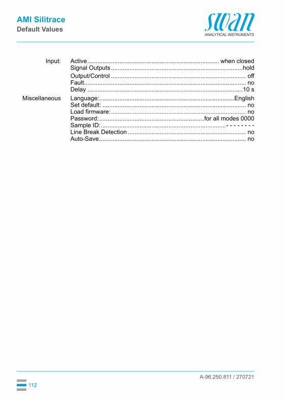
A-96.250.811 / 270721
AMI SilitraceDefault Values
112
Input: Active.............................................................................. when closedSignal Outputs ..............................................................................holdOutput/Control ................................................................................ offFault................................................................................................ noDelay ............................................................................................10 s
Miscellaneous Language:................................................................................EnglishSet default: ..................................................................................... noLoad firmware:................................................................................ noPassword:.............................................................. for all modes 0000Sample ID:..........................................................................- - - - - - - -Line Break Detection ...................................................................... noAuto-Save....................................................................................... no
AMI SilitraceIndex
A-96.250.811 / 270721113
12. Index
AAlarm Relay . . . . . . . . . . . . 11, 28Application Range . . . . . . . . . . 10
BBackground . . . . . . . . . . . . . . 93
CCable thicknesses . . . . . . . . . . 24Calendar . . . . . . . . . . . . . . . 105Changing parameters . . . . . . . . 49Changing values . . . . . . . . . . . 49Cuvette factor . . . . . . . . . . . 72, 90
DDefault Values . . . . . . . . . . . 110Disassemble the solenoid valve . . 75
EError List . . . . . . . . . . . . . . . . 63
FFill system . . . . . . . . . . . . . . . 89
GGrab Sample . . . . . . . . . . . . . 50
HHART . . . . . . . . . . . . . . . . . 33History
Cal. History . . . . . . . . . . . 87Ver. History . . . . . . . . . . . 87Zero History . . . . . . . . . . . 87
IInput . . . . . . . . . . . . . . . . 11, 28
Instrument Overview . . . . . . . . . 16Interface
HART . . . . . . . . . . . . . . . 33Modbus . . . . . . . . . . . . . . 32Profibus . . . . . . . . . . . . . . 32USB . . . . . . . . . . . . . . . . 33
LLonger Stop of Operation. . . . . . . 62
MMeasuring Principle . . . . . . . . . . 10Modbus . . . . . . . . . . . . . . . . . 32Mode External . . . . . . . . . . . . . 95Mode Fieldbus . . . . . . . . . . . . . 94Mode Internal . . . . . . . . . . . . . 94Mounting . . . . . . . . . . . . . . . . 18
OOn-site requirements . . . . . . . . . 14
PP2P
counter. . . . . . . . . . . . . . . 88Diagram . . . . . . . . . . . . . . 88period . . . . . . . . . . . . . . . 88
Power Supply . . . . . . . . . . 14, 27Prepare Maintenance . . . . . . . . . 89Profibus . . . . . . . . . . . . . . . . . 33
RReagent consumption. . . . . . . . . 53Relays. . . . . . . . . . . . . . . . . . 11
SSafety Features . . . . . . . . . . . . 11
AMI SilitraceIndex
A-96.250.811 / 270721114
Sample Flow . . . . . . . . . . . . . . 38Sample requirements . . . . . . . . . 14Setup . . . . . . . . . . . . . . . . . . 34Signal Outputs . . . . . . . . . . 11, 31Silica measurement . . . . . . . . . . 14SilTrace . . . . . . . . . . . . . . . . . 85Software . . . . . . . . . . . . . . . . 48Standard consumption . . . . . . . . 37State Machine . . . . . . . . . . . . . 86System, Description of . . . . . . . . 10
TTechnical Data . . . . . . . . . . . . 16Terminals . . . . . . . 26, 28–29, 32Tube numbering . . . . . . . . . . . 73
UUSB Interface . . . . . . . . . . . . . 33
WWire . . . . . . . . . . . . . . . . . . 24
A-96.250.811 / 270721
AMI SilitraceNotes
115
13. Notes

AMI Silitrace
A-96.250.811 / 270721
Pot
able
Wat
er
Phar
mac
eutic
al W
a et r
Water Steam Cycles
C terHig
ooling Wa
h Purity Water
Waste
tW
aer & Ef uents
Pool &
Sanitary
Swan Analytical Instruments ∙ CH-8340 Hinwil www.swan.ch ∙ [email protected]
Swan Products - Analytical Instruments for:
Swan is represented worldwide by subsidiary companies and distributors and cooperateswith independent representatives all over the world. For contact information, please scanthe QR code.