a-96.250.511 / 091120 operator’s manual - swan
TRANSCRIPT

Operator’s ManualFirmware V6.26 and higher
AMI Turbiwell
A-96.250.511 / 241121

© 2020, Swan Analytische Instrumente AG, Switzerland, all rights reserved.
The information contained in this document is subject to change without notice.
Customer SupportSwan and its representatives maintain a fully trained staff of technical specialists around the world. For any technical question, contact your nearest Swan representative, or the manufacturer:
Swan Analytische Instrumente AGStudbachstrasse 138340 HinwilSwitzerland
Internet: www.swan.chE-mail: [email protected]
Document Status
Title: AMI Turbiwell Operator’s Manual
ID: A-96.250.511
Revision Issue02 July 2009 including auto-drain
03 Jan 2010 incl. W/LED, initial demonstration of performance
04 Jan. 2012 Flow measurement with deltaT flow sensorCalibration functionality implemented
05 Feb. 2013 Update to FW release 5.30Initial demonstration of performance removed.
06 Aug. 2013 Matching function added, mainboard v 2.4
07 Jan. 2014 Wet verification added
08 March 2016 Mainboard V2.5, firmware 6.00
09 July 2020 Mainboard V2.6

A-96.250.511 / 241121
AMI Turbiwell
3
Table of Contents
1. Safety Instructions . . . . . . . . . . . . . . . . . . . . . . . . . . . . . . . . . . . . . . . . . . . . . 51.1. Warning Notices . . . . . . . . . . . . . . . . . . . . . . . . . . . . . . . . . . . . . . . . . . . . . . . . 61.2. General Safety Regulations . . . . . . . . . . . . . . . . . . . . . . . . . . . . . . . . . . . . . . . 81.3. Restrictions for use . . . . . . . . . . . . . . . . . . . . . . . . . . . . . . . . . . . . . . . . . . . . . . 92. Product Description . . . . . . . . . . . . . . . . . . . . . . . . . . . . . . . . . . . . . . . . . . . . 102.1. Instrument Specification . . . . . . . . . . . . . . . . . . . . . . . . . . . . . . . . . . . . . . . . . . 142.2. Instrument Overview . . . . . . . . . . . . . . . . . . . . . . . . . . . . . . . . . . . . . . . . . . . . . 193. Installation . . . . . . . . . . . . . . . . . . . . . . . . . . . . . . . . . . . . . . . . . . . . . . . . . . . . 203.1. Installation Checklist . . . . . . . . . . . . . . . . . . . . . . . . . . . . . . . . . . . . . . . . . . . . . 203.2. Mounting of Instrument Panel . . . . . . . . . . . . . . . . . . . . . . . . . . . . . . . . . . . . . . 213.3. Installation of Sample Degasser Option . . . . . . . . . . . . . . . . . . . . . . . . . . . . . . 233.4. Installation of deltaT Option. . . . . . . . . . . . . . . . . . . . . . . . . . . . . . . . . . . . . . . . 273.5. Installation of Flowcontroller Option . . . . . . . . . . . . . . . . . . . . . . . . . . . . . . . . . 293.6. Connect Sample and Waste . . . . . . . . . . . . . . . . . . . . . . . . . . . . . . . . . . . . . . . 333.7. Electrical Connections. . . . . . . . . . . . . . . . . . . . . . . . . . . . . . . . . . . . . . . . . . . . 363.7.1 Connection Diagram . . . . . . . . . . . . . . . . . . . . . . . . . . . . . . . . . . . . . . . . . . . 383.7.2 Power Supply. . . . . . . . . . . . . . . . . . . . . . . . . . . . . . . . . . . . . . . . . . . . . . . . . 393.8. Relay Contacts . . . . . . . . . . . . . . . . . . . . . . . . . . . . . . . . . . . . . . . . . . . . . . . . . 403.8.1 Input . . . . . . . . . . . . . . . . . . . . . . . . . . . . . . . . . . . . . . . . . . . . . . . . . . . . . . . . 403.8.2 Alarm Relay . . . . . . . . . . . . . . . . . . . . . . . . . . . . . . . . . . . . . . . . . . . . . . . . . . 403.8.3 Relay 1 and 2. . . . . . . . . . . . . . . . . . . . . . . . . . . . . . . . . . . . . . . . . . . . . . . . . 413.9. Signal Outputs. . . . . . . . . . . . . . . . . . . . . . . . . . . . . . . . . . . . . . . . . . . . . . . . . . 433.9.1 Signal Output 1 and 2 (current outputs). . . . . . . . . . . . . . . . . . . . . . . . . . . . . 433.10. Interface Options . . . . . . . . . . . . . . . . . . . . . . . . . . . . . . . . . . . . . . . . . . . . . . . . 433.10.1 Signal Output 3 . . . . . . . . . . . . . . . . . . . . . . . . . . . . . . . . . . . . . . . . . . . . . . . 443.10.2 Profibus, Modbus Interface . . . . . . . . . . . . . . . . . . . . . . . . . . . . . . . . . . . . . . 443.10.3 HART Interface . . . . . . . . . . . . . . . . . . . . . . . . . . . . . . . . . . . . . . . . . . . . . . . 453.10.4 USB Interface. . . . . . . . . . . . . . . . . . . . . . . . . . . . . . . . . . . . . . . . . . . . . . . . . 454. Instrument Setup. . . . . . . . . . . . . . . . . . . . . . . . . . . . . . . . . . . . . . . . . . . . . . . 464.1. Adjusting the deltaT Flow Sensor (Option) . . . . . . . . . . . . . . . . . . . . . . . . . . . . 464.2. Calibration, Matching and Verification. . . . . . . . . . . . . . . . . . . . . . . . . . . . . . . . 474.3. ppm Calculation, e.g. “Oil in water” . . . . . . . . . . . . . . . . . . . . . . . . . . . . . . . . . . 485. Operation . . . . . . . . . . . . . . . . . . . . . . . . . . . . . . . . . . . . . . . . . . . . . . . . . . . . . 515.1. Function of the Keys . . . . . . . . . . . . . . . . . . . . . . . . . . . . . . . . . . . . . . . . . . . . . 515.2. Measured Values and Symbols on the Display. . . . . . . . . . . . . . . . . . . . . . . . . 525.3. Software Structure. . . . . . . . . . . . . . . . . . . . . . . . . . . . . . . . . . . . . . . . . . . . . . . 535.4. Changing Parameters and Values . . . . . . . . . . . . . . . . . . . . . . . . . . . . . . . . . . 54

A-96.250.511 / 241121
AMI Turbiwell
4
6. Maintenance . . . . . . . . . . . . . . . . . . . . . . . . . . . . . . . . . . . . . . . . . . . . . . . . . . . 556.1. Maintenance Schedule. . . . . . . . . . . . . . . . . . . . . . . . . . . . . . . . . . . . . . . . . . . . 556.2. Cleaning the Measuring Chamber . . . . . . . . . . . . . . . . . . . . . . . . . . . . . . . . . . . 566.3. Cleaning the Degasser. . . . . . . . . . . . . . . . . . . . . . . . . . . . . . . . . . . . . . . . . . . . 586.4. Calibration . . . . . . . . . . . . . . . . . . . . . . . . . . . . . . . . . . . . . . . . . . . . . . . . . . . . . 596.5. Verification . . . . . . . . . . . . . . . . . . . . . . . . . . . . . . . . . . . . . . . . . . . . . . . . . . . . . 646.5.1 Swan Verification Kit. . . . . . . . . . . . . . . . . . . . . . . . . . . . . . . . . . . . . . . . . . . . 646.5.2 Wet Verification. . . . . . . . . . . . . . . . . . . . . . . . . . . . . . . . . . . . . . . . . . . . . . . . 726.6. Longer Stop of Operation. . . . . . . . . . . . . . . . . . . . . . . . . . . . . . . . . . . . . . . . . . 747. Troubleshooting. . . . . . . . . . . . . . . . . . . . . . . . . . . . . . . . . . . . . . . . . . . . . . . . 757.1. Calibration Errors . . . . . . . . . . . . . . . . . . . . . . . . . . . . . . . . . . . . . . . . . . . . . . . . 757.2. Matching Errors . . . . . . . . . . . . . . . . . . . . . . . . . . . . . . . . . . . . . . . . . . . . . . . . . 757.3. Verification Errors. . . . . . . . . . . . . . . . . . . . . . . . . . . . . . . . . . . . . . . . . . . . . . . . 757.4. Error List. . . . . . . . . . . . . . . . . . . . . . . . . . . . . . . . . . . . . . . . . . . . . . . . . . . . . . . 767.5. Replacing Fuses . . . . . . . . . . . . . . . . . . . . . . . . . . . . . . . . . . . . . . . . . . . . . . . . 798. Program Overview . . . . . . . . . . . . . . . . . . . . . . . . . . . . . . . . . . . . . . . . . . . . . . 808.1. Messages (Main Menu 1). . . . . . . . . . . . . . . . . . . . . . . . . . . . . . . . . . . . . . . . . . 808.2. Diagnostics (Main Menu 2) . . . . . . . . . . . . . . . . . . . . . . . . . . . . . . . . . . . . . . . . 818.3. Maintenance (Main Menu 3) . . . . . . . . . . . . . . . . . . . . . . . . . . . . . . . . . . . . . . . 828.4. Operation (Main Menu 4) . . . . . . . . . . . . . . . . . . . . . . . . . . . . . . . . . . . . . . . . . . 838.5. Installation (Main Menu 5) . . . . . . . . . . . . . . . . . . . . . . . . . . . . . . . . . . . . . . . . . 849. Program List and Explanations . . . . . . . . . . . . . . . . . . . . . . . . . . . . . . . . . . . 86
1 Messages . . . . . . . . . . . . . . . . . . . . . . . . . . . . . . . . . . . . . . . . . . . . . . . . . . . . 862 Diagnostics . . . . . . . . . . . . . . . . . . . . . . . . . . . . . . . . . . . . . . . . . . . . . . . . . . . 863 Maintenance . . . . . . . . . . . . . . . . . . . . . . . . . . . . . . . . . . . . . . . . . . . . . . . . . . 884 Operation . . . . . . . . . . . . . . . . . . . . . . . . . . . . . . . . . . . . . . . . . . . . . . . . . . . . 925 Installation . . . . . . . . . . . . . . . . . . . . . . . . . . . . . . . . . . . . . . . . . . . . . . . . . . . . 93
10. Default Values . . . . . . . . . . . . . . . . . . . . . . . . . . . . . . . . . . . . . . . . . . . . . . . . . 10411. Index . . . . . . . . . . . . . . . . . . . . . . . . . . . . . . . . . . . . . . . . . . . . . . . . . . . . . . . . . 10612. Notes . . . . . . . . . . . . . . . . . . . . . . . . . . . . . . . . . . . . . . . . . . . . . . . . . . . . . . . . . 108

A-96.250.511 / 241121
AMI TurbiwellSafety Instructions
5
Operator’s ManualThis document describes the main steps for instrument setup, opera-tion and maintenance.
1. Safety Instructions
General The instructions included in this section explain the potential risks associated with instrument operation and provide important safety practices designed to minimize these risks.If you carefully follow the information contained in this section, you can protect yourself from hazards and create a safer work environ-ment.More safety instructions are given throughout this manual, at the re-spective locations where observation is most important. Strictly fol-low all safety instructions in this publication.
Targetaudience
Operator: Qualified person who uses the equipment for its intended purpose.Instrument operation requires thorough knowledge of applications, instrument functions and software program as well as all applicable safety rules and regulations.
OM Location Keep the AMI Operator’s Manual in proximity of the instrument.Qualification,
TrainingTo be qualified for instrument installation and operation, you must: read and understand the instructions in this manual as well as
the Material Safety Data Sheets. know the relevant safety rules and regulations.

A-96.250.511 / 241121
AMI TurbiwellSafety Instructions
6
1.1. Warning NoticesThe symbols used for safety-related notices have the following meaning:
DANGER
Your life or physical wellbeing are in serious danger if such warn-ings are ignored. Follow the prevention instructions carefully.
WARNING
Severe injuries or damage to the equipment can occur if such warnings are ignored. Follow the prevention instructions carefully.
CAUTION
Damage to the equipment, minor injury, malfunctions or incorrect process values can be the consequence if such warnings are ig-nored. Follow the prevention instructions carefully.
MandatorySigns
The mandatory signs in this manual have the following meaning:
Safety goggles
Safety gloves

A-96.250.511 / 241121
AMI TurbiwellSafety Instructions
7
Warning Signs The warning signs in this manual have the following meaning:
Electrical shock hazard
Corrosive
Harmful to health
Flammable
Warning general
Attention general

A-96.250.511 / 241121
AMI TurbiwellSafety Instructions
8
1.2. General Safety RegulationsLegal
RequirementsThe user is responsible for proper system operation. All precautions must be followed to ensure safe operation of the instrument.
Spare Partsand
Disposables
Use only official SWAN spare parts and disposables. If other parts are used during the normal warranty period, the manufacturer’s war-ranty is voided.
Modifications Modifications and instrument upgrades shall only be carried out by an authorized Service Technician. SWAN will not accept responsibili-ty for any claim resulting from unauthorized modification or alter-ation.
WARNING
Electrical Shock HazardIf proper operation is no longer possible, the instrument must be disconnected from all power lines, and measures must be taken to prevent inadvertent operation. To prevent from electrical shock, always make sure that the
ground wire is connected. Service shall be performed by authorized personnel only. Whenever electronic service is required, disconnect instrument
power and power of devices connected to.– relay 1,– relay 2,– alarm relay
WARNING
For safe instrument installation and operation you must read and understand the instructions in this manual.
WARNING
Only SWAN trained and authorized personnel shall perform the tasks described in this document.

A-96.250.511 / 241121
AMI TurbiwellSafety Instructions
9
1.3. Restrictions for useSample Re-quirements
Flow rate: 20–60 l/h Temperature: 1–45 °C. Swan recommends that the sample temperature is no
more than 20 °C above the ambient temperature. The outlet has to be pressure-free against atmosphere. Sample degasser: Only to be used for turbidity below 1 FNU/
NTU. Flow rate of sample inlet at degasser: 10–12 l/h. Maximum turbidity of the sample:
– Turbiwell 7027 and Power: 200 FNU– Turbiwell W/LED: 100 NTU
CAUTION
Wrong measured values due to dirty optical components.Touching the optical components in the cover of the measuring cell may result in wrong measured values.Cleaning and re-calibration at SWAN is necessary. Never touch the optical components.

A-96.250.511 / 241121
AMI TurbiwellProduct Description
10
2. Product Description
Application The AMI Turbiwell is used to measure turbidity in potable water, sur-face water, effluents and water steam cycles.The turbidimeter is also suitable for the measurement of other liquids of which the turbidity correlates with the concentration of a suspend-ed solid or an emulsified liquid, e.g. oil in water. See chapter ppm Calculation, e.g. “Oil in water”, p. 48 for details.
AvailableModels
The instrument is available in three different models: AMI Turbiwell 7027: with an IR LED according to ISO 7027 AMI Turbiwell W/LED: with white light LED (approved, alterna-
tive method to US EPA 180.1) AMI Turbiwell Power: variant on steel panel with IR LED
according to ISO 7027
Configurationsand Options
The AMI Turbiwell 7027 and the AMI Turbiwell W/LED are available in the following configurations: Automatic or manual drain valve Sample degasser (option) deltaT flow sensor (option) Flowcontroller (option) On small panel with remote transmitter
The AMI Turbiwell Power is equipped with a flow meter as standard and available in the following configurations: Automatic or manual drain valve
SignalOutputs
Two signal outputs programmable for measured values (freely scalable, linear or bilinear) or as continuous control output (control parameters programmable).Current loop: 0/4–20 mAMaximal burden: 510 ΩThird signal output available as an option. The third signal output can be operated as a current source or as a current sink (selectable via switch).
Relay Two potential-free contacts programmable as limit switches for mea-sured values, controllers or timer for system cleaning with automatic hold function. Both contacts can be used as normally open or nor-mally closed.Maximum load: 1 A / 250 VAC

A-96.250.511 / 241121
AMI TurbiwellProduct Description
11
Alarm Relay One potential free contact.Alternatively: Open during normal operation, closed on error and loss of
power. Closed during normal operation, open on error and loss of
power.Summary alarm indication for programmable alarm values and in-strument faults.
Input For potential-free contact to freeze the measured value or to interrupt control in automated installations (hold function or remote-off).
SafetyFeatures
No data loss after power failure. All data is saved in non-volatile memory. Overvoltage protection of inputs and outputs. Galvanic sep-aration of measuring inputs from signal outputs.
Communica-tion Interface
(optional)
USB Interface for logger download. RS485 with Fieldbus protocol Modbus or Profibus DP HART interface

A-96.250.511 / 241121
AMI TurbiwellProduct Description
12
MeasuringPrinciple
Nephelometric system: A water sample colored by dissolved sub-stances is a homogeneous system that only attenuates radiation passing through the sample. A water sample containing undissolved substances attenuates radiation and, additionally, the insoluble parti-cles scatter the radiation unequally in all directions.To obtain the turbidity value of the sample, the diffuse radiation is de-termined at an angle of 90°.The AMI Turbiwell uses a non-contact turbidimeter to avoid fouling of optical surfaces.The light beam of the LED (light emitting diode) impinges the water surface and is refracted. At an angle of 90°, the detector measures the incoming, scattered light.
The barrier avoids measurement errors due to light reflections.Depending on the model, the LED emits light with a wavelength of 860 nm (near infrared LED) according to ISO 7027 or in the range from 400 to 600 nm (white LED) as an approved alternative method to US EPA 180.1.
On-lineOperation
The sample enters at the sample inlet [G]. The constant head [H] guarantees a constant sample flow into the measuring chamber [J], and air bubbles are removed. Excess sample overflows directly into waste 1 [I]. The sample flows into the measuring chamber, fills it, and then flows via overflow [F] into waste 1. The LED beam impinges con-tinuously on the calm surface.
ABC
LEDSampleLight beam
DEF
BarrierDetectorDrain
C DA B E F

A-96.250.511 / 241121
AMI TurbiwellProduct Description
13
If the optional sample degasser is used, the sample first flows through this device before entering the measuring chamber.The drain valve [K] is used to empty the measuring chamber for maintenance work like cleaning the measuring chamber or perform-ing a verification.
Verification For the verification, three different verification kits (low turbidity, high turbidity, liquid) can be used. The kits are available as an option.
Calibration The AMI Turbiwell is factory-calibrated, therefore it is not necessary to perform a calibration in the field. The emission intensity of the LED is monitored by an external photodiode. A loss of intensity due to ag-ing will be automatically compensated.To meet the requirements of some public authorities it is possible to calibrate the instrument with a formazine standard.
AEGH
LEDDetectorSample inletConstant head
IJK
Waste 1Measuring chamberManual drain valve waste 2
G
H
I I
J
K K
J
E
FA

A-96.250.511 / 241121
AMI TurbiwellProduct Description
14
2.1. Instrument Specification
Note: • If the maximum sample temperature of 45 °C is exceeded for a
short time, the instrument will not be damaged.• Swan recommends that the sample temperature is no more
than 20 °C above ambient temperature. With increasing temperature difference condensation will form to a higher extent, but the measurement will not be affected. However, it is possible that a temperature difference significantly higher than 20 °C will cause condensation directly on the optics, which can lead to incorrect measurements.
Power Supply AC variant:
DC variant:Power consumption:
100–240 VAC (±10%)50/60 Hz (±5%)10–36 VDCmax. 35 VA
TransmitterSpecifications
Housing:
Range of operation:Storage and transport:Humidity:Display:
aluminum housing with a protection degree of IP 66 / NEMA 4X-10 to +50 °C-30 to +85 °C10–90% rel., non condensingbacklit LCD, 75 x 45 mm
SampleRequirements
Flow rate:
Sample temperature:
Inlet pressure:Outlet pressure:
approx. 20–60 l/h (flow rate through mea-suring chamber: approx. 10–15 l/h)1–45 °C (sample temperature max. 20 °C over ambient temperature)1–10 bar with flow controller optionpressure free
On-site The analyzer site must permit connections to:Requirements Sample inlet:
Sample outlet:Nozzle diam. 10 mm2 drains diam. 16 mm, tubing 15 x 20 mm, which must end in a pressure free waste of sufficient capacity.

A-96.250.511 / 241121
AMI TurbiwellProduct Description
15
TurbidimeterSpecifications
Measuring range: 0.000–200.0 FNU, Turbiwell 70270.000–200.0 FNU, Turbiwell Power0.000–100.0 NTU, Turbiwell W/LED
Precision: ±(0.003 FNU +1% of reading)
Accuracy (based on formazine):
Range 0–40 FNU:±(0.01 FNU +2% of reading)Range >40 FNU:±5% of reading
Response time:Chamber volume:Calibration:Light emitting diode:
t90 typically 3 min0.75 lFactory-calibrated with formazine- IR LED (860 nm) or- white light LED (400–600 nm)

A-96.250.511 / 241121
AMI TurbiwellProduct Description
16
DimensionsTurbiwell 7027and Turbiwell
W/LED
Panel: Dimensions:Screws:Weight:
PVC400x850x200 mm6 pieces, 5 or 6 mm diameter11.0 kg
Exit Enter
AMI Turbiwell
30 mm / 1.18"
13 m
m /
0.51
"
6 x
dia.
6.5
mm
/ 0.
26"
412
mm
/ 16
.22"
850
mm
/ 33
.46"
824
mm
/ 32
.44"
374 mm / 14.72"
400 mm / 15.75"

A-96.250.511 / 241121
AMI TurbiwellProduct Description
17
DimensionsSwansensor
Turbiwell
Turbidity meter mounted on small PVC plate for use with separate transmitter.Dimensions:Screws:Weight:
400x420 mm4 pieces, 5 or 6 mm diameter3.5 kg
13 m
m /
0.51
"
4 x
dia.
6.5
mm
/ 0.
26"
420
mm
/ 16
.54"
394
mm
/ 15
.51"
374 mm / 14.72"
400 mm / 15.75"
30 mm / 1.18"

A-96.250.511 / 241121
AMI TurbiwellProduct Description
18
DimensionsTurbiwell
Power
Panel:Dimensions:Screws:Weight:
stainless steel400x850x150 mm4 pieces, 8 mm diameter14.0 kg
13 m
m /
0.51
"4
x di
a. 1
0 m
m /
0.39
"
850
mm
/ 33
.46"
824
mm
/ 32
.44"
374 mm / 14.72"
400 mm / 15.75"
Exit Enter
AMI Turbiwell

A-96.250.511 / 241121
AMI TurbiwellProduct Description
19
2.2. Instrument Overview
ABC
D
PanelTransmitterCover with optical measurement systemMeasuring chamber
EFGH
Quick fastener screwWaste 1Drain valvedeltaT flow sensor (option)
A
B
C
D
E
FGH

A-96.250.511 / 241121
AMI TurbiwellInstallation
20
3. Installation
3.1. Installation Checklist
On-site requirements
AC variant: 100–240 VAC (10%), 50/60 Hz (5%)DC variant: 10–36 VDCPower consumption: 35 VA maximum.Protective earth connection required.Sample line with sufficient sample flow and pressure (see Instrument Specification, p. 14).
Installation Mount the instrument in vertical position.Display should be at eye level.Connect the sample inlet and waste lines.Adjust the measuring chamber to horizontal position with the adjust-ing screw. Check with spirit level.
Electrical Wiring Do not switch on the Instrument until all electrical connections have been made.Connect all external devices like limit switches, current loops and pumps, see Connection Diagram, p. 38.Connect power cord.
Power-up Turn on the sample flow and wait until the measuring chamber is completely filled.Switch on power.
Instrument Setup
Program all parameters for external devices (interface, etc.).Program all parameters for instrument operation (limits, alarms).
Run-in time Let the instrument operate for 24 h without interruption at normal sample conditions to rinse out any pollution from manufacturing and transport.
Matching Each verikit has to be matched with the current calibration values before it can be used for a verification.
Verification Never perform before the run-in time is over and before the mea-sured value is stable.Can be performed to verify the device functions.

A-96.250.511 / 241121
AMI TurbiwellInstallation
21
3.2. Mounting of Instrument PanelThe first part of this chapter describes the preparing and placing of the system for use. The instrument must only be installed by trained personnel. Mount the instrument in vertical position. For ease of operation mount it so that the display is at eye
level.
Installation ofPVC panel
For the installation a kit containing the following installation material is available:– 6 screws 6x60 mm– 6 dowels– 6 washers 6.4/12 mm
Installation ofsteel panel
For the installation a kit containing the following installation material is available:– 4 screws 8x60 mm– 4 dowels– 4 washers 8.4/24 mm
Mountingrequirements
The instrument is only intended for indoor installation. For dimen-sions, see Instrument Specification, p. 14.
Installationnote
For easy mounting or unmounting of parts behind the measuring chamber [B], the measuring chamber can be swiveled out. To swivel out the measuring chamber, push the locking pin [A] upwards and pull the measuring chamber forward.
AB

A-96.250.511 / 241121
AMI TurbiwellInstallation
22
CAUTION
Inaccurate measured valuesIf the AMI Turbiwell is not exactly aligned in horizontal and verti-cal direction, this can lead to inaccurate measured values. Exactly align the panel in horizontal and vertical direction Use a spirit level to align the panel.
After the panel has been installed and aligned exactly, adjust the Tur-biwell measuring chamber as follows:
1 Put a spirit level onto the measuring chamber [C].2 Turn the adjusting screw [B] clockwise or counter-clockwise until
the measuring chamber is aligned exactly horizontal.
AB
PanelAdjusting screw
CD
Measuring chamberSpirit level
AMI Turbiwell AMI Turbiwell
BA C D

A-96.250.511 / 241121
AMI TurbiwellInstallation
23
3.3. Installation of Sample Degasser OptionOverview
ABCDEFG
Star knobCoverCylinder pin (diam. 6 mm)BracketFixing screws (4 pcs)Plates (12 pcs)Counter nut
HIJKLM
Base plateConsoleSample inletHole 5 mmOutlet to measuring chamberOverflow to waste
A
BCDE
F
GHIJKLM

A-96.250.511 / 241121
AMI TurbiwellInstallation
24
Installation
1 Screw the brackets [D] to the panel with the enclosed M6 x 16 screws
2 Roughly align the brackets and slightly tighten the screws.3 Insert the guide pins [C] into the bores of the brackets.4 Screw the console [I] to the panel with the M4 x 16 screws [K].
CDIK
Guide pinBracketConsoleHole 5 mm
C
D
IK
A-96.250.511 / 241121
AMI TurbiwellInstallation
25
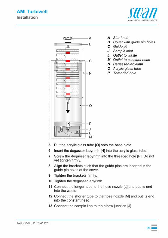
5 Put the acrylic glass tube [O] onto the base plate.6 Insert the degasser labyrinth [N] into the acrylic glass tube.7 Screw the degasser labyrinth into the threaded hole [P]. Do not
yet tighten firmly.8 Align the brackets such that the guide pins are inserted in the
guide pin holes of the cover.9 Tighten the brackets firmly.10 Tighten the degasser labyrinth.11 Connect the longer tube to the hose nozzle [L] and put its end
into the waste.12 Connect the shorter tube to the hose nozzle [M] and put its end
into the constant head.13 Connect the sample line to the elbow junction [J].
ABCJLMNOP
Star knobCover with guide pin holesGuide pinSample inletOutlet to wasteOutlet to constant headDegasser labyrinthAcrylic glass tubeThreaded hole
A
B
C
N
O
PJLM

A-96.250.511 / 241121
AMI TurbiwellInstallation
26
14 Replace the elbow hose nozzle [Q] on the constant head with the enclosed blind screw [R].
Q Elbow hose nozzle R Blind screw
R
Q

A-96.250.511 / 241121
AMI TurbiwellInstallation
27
3.4. Installation of deltaT OptionOverview
Installation Install the deltaT sensor in vertical position with the sample inlet [A] looking downwards.
1 Push the locking pin [D] upward to unlock the measuring chamber.
2 Swivel the measuring chamber [G] out.3 Remove the sample inlet tube from the elbow hose nozzle [E].4 Unscrew and remove the screw [J].5 Remove the locking plate [I].
ABCDE
Sample inletdeltaT sensorSample outletLocking pinElbow hose nozzle
FGHIJ
Manual drain valveMeasuring chamberPanelLocking plateScrew
C DAB E E I JF G H

A-96.250.511 / 241121
AMI TurbiwellInstallation
28
6 Turn the elbow hose nozzle [E] upwards clockwise.7 Install the locking plate [I]8 Tighten the screw [J].9 Screw the deltaT sensor [B] to the panel in vertical position.10 Connect the tube supplied with the installation kit to the sample
outlet [C] of the deltaT sensor and to the sample inlet (elbow hose nozzle [E]) of the constant head.
11 Connect the sample inlet tube to sample inlet [A] of the deltaT sensor.
12 Push the locking pin upward and swivel the measuring chamber back.
13 Make sure that the measuring chamber rests in locked position.
ElectricalConnection
WARNING
Electrical shock hazardBefore opening the AMI Transmitter switch power off.
14 Use one of the PG7 cable glands to feed the cable of the sensor into the AMI transmitter housing.
15 Connect the cable to the terminals according to the Connection Diagram, p. 38.

A-96.250.511 / 241121
AMI TurbiwellInstallation
29
3.5. Installation of Flowcontroller OptionPreparations 1 Push the locking pin [D] upward to unlock the measuring
chamber.2 Swivel the measuring chamber [G] out.3 Remove the sample inlet tube from the elbow hose nozzle [A].4 Unscrew and remove the screw [J].5 Remove the locking plate [I].6 Unscrew the elbow hose nozzle [A] from the constant head.
ADG
Elbow hose nozzleLocking pinMeasuring chamber
IJ
Locking plateScrew
A GD I J

A-96.250.511 / 241121
AMI TurbiwellInstallation
30
7 Unscrew the elbow fitting [E] from the inlet of the Flowcontroller.
8 Remove the teflon tape from the threads of fittings [A] and [E] and wrap them with new teflon tape.
9 Screw the elbow fitting [E] to the inlet of the constant head and the elbow hose nozzle [A] to the inlet of the flow controller.
10 Install the locking plate [I].11 Tighten the screw [J].
CE
FlowcontrollerElbow fitting
EC

A-96.250.511 / 241121
AMI TurbiwellInstallation
31
Overview
Installation 12 Screw the Flowcontroller [C] to the panel.13 Connect the tube supplied with the installation kit to the sample
outlet of the Flowcontroller and to the sample inlet [E] of the con-stant head.
14 Connect the sample inlet tube to sample inlet [A] of the Flowcon-troller. Depending on the inlet pressure, secure the tube to the el-bow hose nozzle [A] with a clamp.
15 Push the locking pin upward and swivel the measuring chamber back.
16 Make sure that the measuring chamber rests in locked position.
ABCD
Sample inlet of FlowcontrollerCapillaryFlowcontrollerLocking pin
EFGH
Elbow fittingManual drain valveMeasuring chamberPanel
CBA D E F G H

A-96.250.511 / 241121
AMI TurbiwellInstallation
32
ElectricalConnection
WARNING
Electrical shock hazardBefore opening the AMI Transmitter switch power off.
17 Use one of the PG7 cable glands to feed the cable of the sensor into the AMI transmitter housing.
18 Connect the cable to the terminals according to the Connection Diagram, p. 38.
Exchangingthe capillary
The capillary determines the flow resistance and the maximum flow rate. With the pressure regulator at the inlet side of the capillary the flow rate can be adjusted within the given range, see diagram below.The standard capillary is an FEP tube with an inner diameter of 1 mm and a length of 500 mm. If you have a low sample pressure or you need a high sample flow, a shorter capillary with 186 mm length can be used.
00
5
10
15
20
25
30
35
40
0.5 1 bar
l/h
1.5 2 2.5 3 3.5
186
500

A-96.250.511 / 241121
AMI TurbiwellInstallation
33
3.6. Connect Sample and WasteSample inlet The AMI Turbiwell can be ordered in different configurations. Use
plastic tubes with inner diameter 10 mm for: connection to the constant head connection to the deltaT flow meter connection to the Flowcontroller
Use plastic tubes with outer diameter 6 mm for connection to the de-gasser.
Waste Use 1/2” tubes and connect them to the hose nozzles of the drain [B] and waste [C] and place them into an atmospheric drain of sufficient capacity.
Basicconfiguration
A
BC
Constant head sample inletDrainWaste
A B C

A-96.250.511 / 241121
AMI TurbiwellInstallation
34
deltaT sensor
Flowcontroller
D
BC
deltaT sensor sample inlet DrainWaste
D B C
EF
BC
CapillaryFlowcontroller sample inlet DrainWaste
FE B C

A-96.250.511 / 241121
AMI TurbiwellInstallation
35
Degasser GBC
Degasser sample inletDrainWaste
BG C

A-96.250.511 / 241121
AMI TurbiwellInstallation
36
3.7. Electrical Connections
WARNING
Electrical hazard. Always turn off power before manipulating electric parts. Grounding requirements: Only operate the instrument from a
power outlet which has a ground connection. Make sure the power specification of the instrument corre-
sponds to the power on site.
Cablethicknesses
In order to comply with IP66, use the following cable thicknesses
Note: Protect unused cable glands
Wire For Power and Relays: Use max. 1.5 mm2 / AWG 14 stranded wire with end sleeves.
For Signal Outputs and Input: Use 0.25 mm2 / AWG 23 stranded wire with end sleeves.
ABC
PG 11 cable gland: cable Øouter 5–10 mmPG 7 cable gland: cable Øouter 3–6.5 mmPG 9 cable gland: cable Øouter 4–8 mm
A B C

A-96.250.511 / 241121
AMI TurbiwellInstallation
37
WARNING
External Voltage.Externally supplied devices connected to relay 1 or 2 or to the alarm relay can cause electrical shocks Make sure that the devices connected to the following contacts
are disconnected from the power before resuming installation.– relay 1– relay 2– alarm relay
WARNING
To prevent from electrical shock, do not connect the instrument to the power unless the ground wire (PE) is connected.
WARNING
The mains of the AMI Transmitter must be secured by a main switch and appropriate fuse or circuit breaker.

A-96.250.511 / 241121
AMI TurbiwellInstallation
38
3.7.1 Connection Diagram
CAUTION
Use only the terminals shown in this diagram, and only for the mentioned purpose. Use of any other terminals will cause short circuits with possible corresponding consequences to material and personnel.

A-96.250.511 / 241121
AMI TurbiwellInstallation
39
3.7.2 Power Supply
WARNING
Risk of electrical shockInstallation and maintenance of electrical parts must be per-formed by professionals. Always turn off power before manipulat-ing electric parts.
Note: The protective earth wire (ground) has to be connected to the grounding terminal.
Installationrequirements
The installation must meet the following requirements. Mains cable to comply with standards IEC 60227 or IEC
60245; flammable rating FV1 Mains equipped with an external switch or circuit-breaker
– near the instrument– easily accessible to the operator– marked as interrupter for AMI Turbiwell
ABCD
Power supply connectorNeutral/(-) conductor, Terminal 2Phase/(+) conductor, Terminal 1Protective earth PE
A
B
C
D

A-96.250.511 / 241121
AMI TurbiwellInstallation
40
3.8. Relay Contacts
3.8.1 InputNote: Use only potential-free (dry) contacts.The total resistance (sum of cable resistance and resistance of the relay contact) must be less than 50 Ω.
Terminals 16/42If signal output is set to hold, measurement is interrupted if input is active.For programming see menu 5.3.4, p. 101.
3.8.2 Alarm RelayNote: Max. load 1 A (time-lag) / 250 VAC
Alarm output for system errors.Error codes see Error List, p. 76
Note: With certain alarms and certain settings of the AMI transmitter the alarm relay does not switch. The error, however, is shown on the display.
1) usual use
Terminals Description Relay connection
NC1)
Nor-mally Closed
10/11 Active (opened) during normal operation.Inactive (closed) on error and loss of power.
NONormallyOpen
12/11 Active (closed) during normal operation.Inactive (opened) on error and loss of power.
10
12
11
0V
1)
10
12
11
0V

A-96.250.511 / 241121
AMI TurbiwellInstallation
41
3.8.3 Relay 1 and 2Note: Max. load 1 A/250 VAC
Relay 1 and 2 can be configured as normally open or as normally closed. Standard for both relays is normally open. To configure a Re-lay as normally closed, set the jumper in the upper position.
Note: Some error codes and the instrument status may influence the status of the relays described below.
For programming see Menu Installation 5.3.2 & 5.3.3, p. 97.
Relay config. Terminals
Jumper pos. Description Relay configuration
NormallyOpen
6/7: Relay 18/9: Relay 2
Inactive (opened) during normal operation and loss of power.Active (closed) when a programmed function is executed.
NormallyClosed
6/7: Relay 18/9: Relay 2
Inactive (closed) during normal operation and loss of power.Active (opened) when a programmed function is executed.
6
0V7
6
0V7
AB
Jumper set as normally open (standard setting)Jumper set as normally closed
AB

A-96.250.511 / 241121
AMI TurbiwellInstallation
42
CAUTION
Risk of damage of the relays in the AMI Transmitter due to heavy inductive load.Heavy inductive or directly controlled loads (solenoid valves, dos-ing pumps) may destroy the relay contacts. To switch inductive loads > 0.1 A use an AMI relay box
available as an option or suitable external power relays.
Inductive load Small inductive loads (max 0.1 A) as for example the coil of a power relay can be switched directly. To avoid noise voltage in the AMI Transmitter it is mandatory to connect a snubber circuit in paral-lel to the load. A snubber is not necessary if an AMI relaybox is used.
Resistive load Resistive loads (max. 1 A) and control signals for PLC, impulse pumps and so on can be connected without further measures
Actuators Actuators, like motor valves, are using both relays: One relay contact is used for opening, the other for closing the valve, i.e. with the 2 re-lay contacts available, only one motor valve can be controlled. Mo-tors with loads bigger than 0.1 A must be controlled via external power relays or an AMI relay box.
ABCDE
AC or DC power supplyAMI TransmitterExternal power relaySnubberPower relay coil
AB C
D E
ABC
AMI TransmitterPLC or controlled pulse pumpLogic
A B
C
ABC
AC or DC power supplyAMI TransmitterActuator
M
AB C

A-96.250.511 / 241121
AMI TurbiwellInstallation
43
3.9. Signal Outputs
3.9.1 Signal Output 1 and 2 (current outputs)Note: Max. burden 510 ΩIf signals are sent to two different receivers, use signal isolator (loop isolator).
Signal output 1: Terminals 14 (+) and 13 (-)Signal output 2: Terminals 15 (+) and 13 (-)For programming see Program List and Explanations, p. 86, Menu Installation.
3.10. Interface Options
The slot for interfaces can be used to expand the functionality of the AMI instrument with either: a Profibus or Modbus connection a HART connection an USB Interface
ABC
AMI TransmitterSlot for interfacesScrew terminals
A
B
C

A-96.250.511 / 241121
AMI TurbiwellInstallation
44
3.10.1 Signal Output 3The AMI Turbiwell can display a maximum of two measured values: the measured turbidity and the sample flow, if a flow sensor is installed.
Therefore, there is no need to install the optional third signal output.
3.10.2 Profibus, Modbus InterfaceTerminal 37 PB, Terminal 38 PATo connect several instruments by means of a network or to config-ure a PROFIBUS DP connection, consult the PROFIBUS manual. Use appropriate network cable.
Note: The switch must be ON, if only one instrument is installed, or on the last instrument in the bus.
Profibus, Modbus Interface PCB (RS 485)A On - OFF switch
ON
OFF
A

A-96.250.511 / 241121
AMI TurbiwellInstallation
45
3.10.3 HART InterfaceTerminals 38 (+) and 37 (-).The HART interface PCB allows for communication via the HART protocol. For detailed information, consult the HART manual.
HART Interface PCB
3.10.4 USB InterfaceThe USB Interface is used to store Logger data and for Firmware up-load. For detailed information see the corresponding installation in-struction.
USB Interface

A-96.250.511 / 241121
AMI TurbiwellInstrument Setup
46
4. Instrument SetupOpen sample
flowOpen the sample flow and wait until the measuring chamber is full and the sample flows via overflow into the waste.Switch on power.First, the analyzer performs a self test, displays the firmware version and then starts normal operation.
Programming Program all parameters for external devices (interface, etc.). Set all parameters for instrument operation (limits, alarms).
Run-in period If the turbidity value is very low (<1 FNU/NTU) rinsing may take sev-eral hours (~24 h). Rinse until a constant value is displayed.
4.1. Adjusting the deltaT Flow Sensor (Option)The accuracy of the flow measurement depends on the ambient tem-perature of the installation location. The deltaT flow sensor is factory calibrated at 20 °C (±20 % accuracy). If the temperature is higher or lower, the deltaT flow sensor can be adjusted.To adjust the deltaT sensor proceed as follows:
Run in After installation let the sensor run in for at least 1h.Determine the
flow rate1 Put the sample outlet of the instrument into a measuring cup with
a sufficient volume for 10 min.2 To get the flow rate in l/h, calculate the amount of water con-
tained in the measuring cup with factor 6. The flow rate in l/h results from the multiplication of the
amount of water after 10 min by 6.
Adjust slope 1 Navigate to <Installation>/<Sensors>/<Flow>, choose <Slope> and press [Enter].
2 If the calculated flow rate is higher than the displayed flow rate in-crease the Slope value.
3 If the calculated flow rate is lower than the displayed flow rate de-crease the Slope value.
4 Press [Exit] and save with [Enter].5 Compare the calculated flow rate with the displayed flow rate.
If the flow rates are roughly equal, the adjustment is finished.6 Else repeat steps 1 to 5.

A-96.250.511 / 241121
AMI TurbiwellInstrument Setup
47
4.2. Calibration, Matching and VerificationCalibration If required by the local regulatory authority, a calibration can be car-
ried out at the customer's site. This calibration is performed with a specified formazine standard, see Calibration, p. 59 for details. The zero point defined during factory calibration is not changed by this calibration, but only the slope of the calibration line. The calibration is accepted if the deviation is less than 25% of the factory calibration.The long-term stability of the AMI Turbiwell can be verified with a ver-ification kit that must be matched against the current calibration.
Matching Matching a verikit is necessary to measure and store the specific tur-bidity of a verikit. Each subsequent verification using the respective verikit is based on this value.With a verikit that has been matched, you can carry out a periodic verification. The deviation must be within 10% of the reference val-ue.
Verification Perform a verification with a verikit (see Swan Verification Kit, p. 64) or a wet verification (see Wet Verification, p. 72) after run-in time to check the instrument performance.

A-96.250.511 / 241121
AMI TurbiwellInstrument Setup
48
4.3. ppm Calculation, e.g. “Oil in water”Note: If ppm is chosen, the matching and verification functions are not available.
General The AMI Turbiwell is also suitable for the measurement of other liq-uids of which the turbidity correlates with the concentration of a sus-pended solid or an emulsified liquid. In such applications, the turbidity is normally displayed in ppm. A submenu allows the user to perform a calibration of such processes.The calibration line is defined by 2 points: zero point and a scale point (slope). For the determination of the zero point, a sample with-out the opacifier (x = 0) must be supplied to the AMI Turbiwell. The average value over a defined time period is automatically saved as the zero point.For the determination of the slope, the AMI Turbiwell must be sup-plied with a sample with a known concentration of turbidity material (opacifier). The concentration of the opacifier must be entered into the transmitter (i.e. 2.5 ppm). The average value over a defined time is automatically saved as slope (scale point).The calibration line is calculated from this data.
Note: Two restrictions regarding this calibration method must be considered:• The reading is only valid if the zero does not change. This
means that the background turbidity which is caused by different properties or different suspended solids must be constant!
• In general, the correlation of the displayed value (ppm) and content of the opacifier is only approximately linear in a limited range. Due to that fact the sensitivity is strongly dependent on the chosen concentration (scale point). If the scale point is chosen so that it is close to a limit value or a control point (i.e. setpoint), the error caused by non-linearity in this range can be minimized.
It must also be taken into consideration that the turbidity of a sample does not only depend on the concentration of the suspended solid or emulsified liquid, but also on the drop size, respectively, particle size distribution function. This property of the sample should not differ substantially.

A-96.250.511 / 241121
AMI TurbiwellInstrument Setup
49
Considerations Considerations for a reliable measurement: The sample must always have the same grade of homogeniza-
tion to receive quantitative results. Adequate homogenization can be achieved with a centrifugal or a gear pump.
The distance and the time period from sampling to measure-ment should be short enough to ensure that the drop size does not essentially change.
It is not possible to avoid the accumulation of a thin layer of oil on the walls of pipes, fittings and measuring chamber when measuring samples with permanent oil content. If the oil con-centration in the sample decreases, part of the oil layer is re-moved. This is a very slow process so it can take a long time until the actual concentration is displayed correctly. In the case of measurements with varying concentrations, an (automatic) cleaning of the sampling system is recommended, especially when low concentrations need to be determined with a high ac-curacy.
The solubility of most oils in water is very low but depending on the type of oil, several ppm are dissolved in water. This dis-solved oil cannot be detected by turbidimeters. The value of the dissolved part of the oil must be added to the undissolved part to determine a limit value correctly.
The sensitivity varies in different oils. A typical comparative value for 1 ppm of oil is 0.5 FNU/NTU.
Activate ppmcalculation
To activate <ppm calculation>, navigate to menu <Installation>/<Sensors>/<Dimension>. Choose ppm, press [Enter], press [Exit].Choose <Yes> and press [Enter] to save.

A-96.250.511 / 241121
AMI TurbiwellInstrument Setup
50
Processcalibration
The following must be considered before starting calibration: Drain the measuring chamber and clean it if necessary. For the calibration, oil-free process water and oil is needed.
The calibration solutions are prepared in a vessel with a vol-ume of approx.10 liters.
Homogenize the solution with a circulating pump or a motor-ized stirrer before and during the calibration.
Connect the outlet of the vessel with the sample inlet of the AMI Turbiwell.
Adjust the sample flow to approx. 20 liters per hour by a control valve.
The signal must be stable while the sample is flowing. To check the stability, navigate to menu 2.2.1 <Diagnostic>/<Sensors>/<Turbidity> and observe the raw signal.
To start with calibration navigate to menu 3.1, <Maintenance>/<Process Cal. ppm>. There you can choose between Detect Zero:
The zero value determination is carried out with oil-free pro-cess water.
Specify slope:A sample with a known oil concentration is used to determine the slope. The entered process value is used as the setpoint of the calibration sample.

A-96.250.511 / 241121
AMI TurbiwellOperation
51
5. Operation
5.1. Function of the Keys
ProgramAccess, Exit
A to exit a menu or command (rejecting any changes) to move back to the previous menu level
B to move DOWN in a menu list and to decrease digits
C to move UP in a menu list and to increase digits
D to open a selected sub-menu to accept an entry
Exit Enter
B C DA
35.8 l/h
RUN 14:10:45R1
2.53 FNUR2
1
InstallationOperation
DiagnosticsMessages
Maintenance
Main MenuEnter
Exit

A-96.250.511 / 241121
AMI TurbiwellOperation
52
5.2. Measured Values and Symbols on the Display
Relay status, symbols
A RUN normal operationHOLD input closed or cal delay: Instrument on hold (shows
status of signal outputs).OFF input closed: Control/limit is interrupted (shows status
of signal outputs).B ERROR Error Fatal Error
C Transmitter control via ProfibusD TimeE Process valueF Sample FlowG Relay Status
upper/lower limit not yet reachedupper/lower limit reachedcontrol upw./downw. no action
control upw./downw. active, dark bar indicates control intensity
motor valve closedmotor valve: open, dark bar indicates approx. positiontimertimer: timing active (hand rotating)
RUN 15:20:18
R1
R2
35.8 l/h
FNU2.53
A B C
E
FG
D

A-96.250.511 / 241121
AMI TurbiwellOperation
53
5.3. Software Structure
1
Messages
OperationMaintenanceDiagnostics
Main Menu
Menu 4: OperationSubset of menu 5 - installation, but process-related. User relevant parameters that might need to be modi-fied during daily routine. Normally password protected and used by the process-operator.
Menu 1: MessagesReveals pending errors as well as an event history (time and state of events that have occurred at an ear-lier point of time) and maintenance requests. It contains user relevant data.
Menu 2: DiagnosticsProvides user relevant instrument and sample data.
Menu 5: InstallationFor initial instrument set up by SWAN authorized per-sons, to set all instrument parameters. Can be pro-tected by means of a password.
Menu 3: MaintenanceFor instrument calibration, service, relay and signal output simulation and to set the instrument time. It is used by the service personnel.
Installation
1.1
Message List
Messages
2.1
InterfaceI/O StateSample
IdentificationSensors
Diagnostics
4.1
LoggerRelay ContactsSensorsOperation
5.1
InterfaceMiscellaneousRelay Contacts
SensorsSignal Outputs
Installation
Pending ErrorsMaintenance List
3,1
Verification
Calibration
Maintenance
Simulation
Matching
Set Time 01.01.05 16:30:00

A-96.250.511 / 241121
AMI TurbiwellOperation
54
5.4. Changing Parameters and ValuesChanging
parametersThe following example shows how to change the logger interval:
Changingvalues
1 Select the parameter you want to change.
2 Press [Enter]
3 Press [ ] or [ ] key to highlight the required parameter.
4 Press [Enter] to confirm the selec-tion or [Exit] to keep the previous parameter).
The selected parameter is highlighted but not saved yet.
5 Press [Exit].
Yes is highlighted.6 Press [Enter] to save the new pa-
rameter. The system reboots, the new
parameter is set.
5.1.2SensorsSensor type FOME
Temperature NT5KStandards
Disinf. Free chlorine
4.4.1LoggerLog interval 30 minClear logger no
4.1.3Logger
Clear logger noLog interval 30min
1 Hour
Interval.5 min
30 min10 min
4.1.3LoggerLog interval 10 minClear logger no
4.1.3LoggerLog intervalClear logger no
No
Save ?Yes
1 Select the value you want to change.
2 Press [Enter].3 Set required value with [ ] or
[ ] key.
4 Press [Enter] to confirm the new value.
5 Press [Exit]. Yes is highlighted.
6 Press [Enter] to save the new val-ue.
5.3.1.1.1
Alarm High 200.0 FNUAlarm
Alarm Low 0.000 FNUHysteresis 10.0 FNUDelay 5 Sec
5.3.1.1.1Alarm
Alarm Low 0.000 FNUHysteresis 10.0 FNUDelay 5 Sec
Alarm High 180.0 FNU

A-96.250.511 / 241121
AMI TurbiwellMaintenance
55
6. Maintenance
6.1. Maintenance ScheduleThe AMI Turbiwell is factory-calibrated using a primary standard(formazine) prior to shipment. The instrument does not require any further calibration before use. A verification is recommended quarter-ly using the Swan Verification Kit, a secondary standard, instead of calibration with a primary standard.Recalibration with a primary standard is only necessary if verification of the turbidity meter fails or after significant maintenance or repair work.Preventive maintenance frequency depends on water quality, on the application, and on national regulations.
Turbidity below 1 FNU/NTU:
Turbidity above 1 FNU/NTU:
Every week Check sample supply for dirt.Check sample flow.
Monthly Check measuring chamber for dirt. If necessary, clean it with a brush and/or drain the measuring chamber. If there is a growth of algae, disinfect the sample degasser and measuring chamber with concentrated NaOCl. Use a pipette to dose the disinfectant.
Quarterly Perform a verification.Yearly Dismount the sample degasser and clean it with a brush.
Daily to every week
Check sample supply for dirt.Check sample flow.
Weekly to Monthly
Rinse the measuring chamber.If the sample contains algae, disinfect the measuring chamber with concentrated NaOCl. Use a pipette.
Quarterly Perform a verification.

A-96.250.511 / 241121
AMI TurbiwellMaintenance
56
6.2. Cleaning the Measuring Chamber
CAUTION
Wrong measured values due to dirty optical componentsTouching the optical components in the cover of the measuring cell may result in wrong measured values.Cleaning and re-calibration at SWAN is necessary. Never touch the optical components during maintenance work.
Signal outputsand relays
During the cleaning routine, no turbidity or flow alarms are issued. The measured value is kept at the last valid value and the relays are frozen. If programmed, the controller continues based on the last val-id value.
Cleaning
1 Select <Maintenance>/<Clean meas. chamber>. The instrument counts down 1200 seconds during which the
measuring chamber can be checked and cleaned. The routine can be terminated at any time by pressing [Enter]. The counter can be restarted by pressing an arrow key.
2 Stop sample flow.3 Release the two quick fastener screws [C].
The cover automatically slides up.
ABCDE
Drain valveMeasuring chamberQuick fastener screwCoverPanel
A B C D E

A-96.250.511 / 241121
AMI TurbiwellMaintenance
57
4 Move the cover completely backwards.5 If the measuring chamber is strongly polluted, remove algae etc.
from the barrier and measuring chamber walls with a soft brush.6 Open the drain valve to flush out the polluted water.7 Remove calcareous depositions using a common household de-
liming agent in standard concentration. For that, fill up the mea-suring chamber, add the deliming agent.
8 Wait several minutes, then remove the calcareous depositions with a soft brush.
9 Open the drain valve to flush out the polluted water.10 Close the drain valve, start sample flow and wait until the mea-
suring chamber has been filled.11 Open the drain valve to flush again.12 If necessary repeat steps 9 and 10.13 Move the cover right to the front.14 Press the cover down and fix it with the quick fastener screws.
Note: Before exiting the routine or before the 1200 seconds have elapsed, completely fill and close the measuring chamber and open the flow regulating valve.
Run-in Period After cleaning, wait approximately 1 h (depending on the sample flow) until a stable value is displayed.

A-96.250.511 / 241121
AMI TurbiwellMaintenance
58
6.3. Cleaning the DegasserNote: Use a soft brush and a mild detergent. Eliminate calcareous depositions with a common household deliming agent in standard concentration.
Cleaning To clean the degasser proceed as follows:
1 Stop sample flow.2 Wait until the sample degasser is empty.3 Turn the star knob [A] counter-clockwise to unscrew and remove
the degasser labyrinth form the base plate [G].4 Remove the acrylic glass tube [F].5 Loosen the counter nut [E] and remove both, counter nut and nut.6 Remove the plates [C] from the guide rod.7 Clean the plates and the acrylic glass tube with a soft brush and
mild detergent.8 Eliminate calcareous depositions using a common household de-
liming agent in standard concentration.9 Rinse the plates and acrylic glass tube with clean water.10 Assemble alternately a plate with a white and a red distance
holder to the guide rod. Start with a white plate.
ABCDEFG
Star knobCover with guide pin holesPlateDegasser labyrinthCounter nutAcrylic glass tubeBase plate
AB
G
C
D
E
F

A-96.250.511 / 241121
AMI TurbiwellMaintenance
59
11 Wipe the sample degasser bottom plate with a soft tissue. Make sure that the gasket is clean.
12 Put the acrylic glass tube onto the base plate.13 Insert the degasser labyrinth into the acrylic glass tube.14 Tighten the degasser labyrinth finger tight with the star knob 15 Open the sample flow.16 Check for leakage.
6.4. CalibrationThe AMI Turbiwell is calibrated at the factory using formazine and the curve is permanently stored in the transmitter. In addition, the emission intensity of the LED is monitored by an external photodi-ode. This automatically compensates for an age-related loss of in-tensity. A recalibration of the AMI Turbiwell is therefore not necessary.However, some state regulations require a periodic recalibration of turbidity measuring instruments. Therefore, a calibration procedure is described below. To find out whether a periodic recalibration is re-quired, contact your local regulatory authority.
Note: The zero point defined during factory calibration is not changed, but only the slope of the calibration line.
The calibration is performed with a 20 FNU/NTU formazine standard. To make the formazine standard, the following aids are required: Deionized water with a turbidity < 0.1 FNU/NTU Formazine standard 4000 NTU produced according to
EPA 180.1, ASTM 2130B or ISO 7027 The following laboratory equipment

A-96.250.511 / 241121
AMI TurbiwellMaintenance
60
Prepare the20 NTU
formazinestandard
1 Put the pipette into the fast-release pipette pump.2 Make sure that the pump piston is pushed in completely.3 Turn the pump wheel until the formazine standard 4000 NTU
reaches the 5 ml level of the pipette.4 Put the pipette into the volumetric flask and press the fast release
lever until the pipette is empty.5 Fill the volumetric flask with 1 liter of deionized dilution water.
WARNING
Health hazardFormazine is harmful to the environment. At no means recirculate it into the water system.
AB
CD
Pipette 5 mlFast-release pipette pumpRubber stopperVolumetric flask
A B C D

A-96.250.511 / 241121
AMI TurbiwellMaintenance
61
Performcalibration
In the maintenance menu, choose calibration and follow the instruc-tions on the screen.
1 Navigate to menu <Maintenance>/<Calibration> and press [Enter].
2 Stop sample flow.3 Open the measuring chamber.
4 Seal the overflow [E] with the rubber stopper [F].See Seal the overflow, p. 63.
5 Open the drain valve [D] until the measuring chamber is empty. If equipped with automatic
drainage, the drain valve opens and closes automatically.
6 Then close the drain valve again.7 First fill the overflow chamber [C]
with the formazine standard.8 Then fill the measuring chamber [B]
until the formazine standard over-flows via constant head [G].
9 Close the measuring chamber.10 Press [Enter] to start calibration.
After the calibration has been finished, the current value and the calculated factor are displayed. If the calculated factor is within the limit of 0.75–1.25 the calibration is accepted.
3.32
VerificationMaintenance
Set Time 01.01.05 16:30:00
Matching
SimulationCalibration
3.32.5
- Stop sample flowCalibration
- Open meas. chamber
<Enter> to continue
3.32.5
- Plug drain 1 with aCalibration
rubber stopper
<Enter> to continue
3.32.5
- Open Drainage ValveCalibration
- Empty meas. chamber
<Enter> to continue
- Drainage valve open?
3.32.5
- Close Drainage Valve
- Close meas. chamber
Calibration
- Drainage valve closed?
<Enter> to continue
- Fill with Formazine
3.32.5
Current Value 10.1 FNUCalibration
Factor (0.75 - 1.25) 0.92
<Enter> to continue

A-96.250.511 / 241121
AMI TurbiwellMaintenance
62
Possible error messages, see Troubleshooting, p. 75.
You are prompted to choose between:[Keep existing] and[Save new].
11 Open the measuring chamber.12 Open the drain valve.13 Remove the rubber stopper.14 Rinse the measuring chamber with
sample.
15 Close the measuring chamber.16 Close the drain valve.17 Press [Enter].
You are asked whether you want to match the Verikit. Without a matched Verikit it is not possible to perform a ver-ification. It is also possible to match a Verikit later, see Matching, p. 64.
18 Start sample flow.
3.32.4
Factor existing 1.00
Save new
Calibration
Factor new 0.92Keep existing
3.32.5
- Open meas. chamber
- Rinse meas. chamber
Calibration
- Drainage valve open?- Remove rubber stopper
<Enter> to continue
3.32.5
- Close meas. chamberCalibration
- Close Drainage Valve- Drainage valve closed?
<Enter> to continue
3.32.4
- Match Verikit?Calibration
NoYes
3.32.5
- Start sample flowCalibration
<Enter> to finish

A-96.250.511 / 241121
AMI TurbiwellMaintenance
63
Seal theoverflow
ABC
CoverMeasuring chamberOverflow chamber
DEF
Drain valveOverflow (drain 1)Rubber stopper
ABCDEFG
CoverMeasuring chamberOverflow chamberDrain valveOverflow (Drain 1)Rubber stopperConstant head
A B C D FE
A
EF
BCG
D

A-96.250.511 / 241121
AMI TurbiwellMaintenance
64
6.5. VerificationDue to the technology and design of the instrument, a calibration is not required. However, a periodic check of the instrument perfor-mance can be performed. The check can be performed either with a Swan Verification Kit or with a wet verification. To find out which methods are approved, contact your local regulatory authority.
6.5.1 Swan Verification KitThere are two different types of Swan Verification Kits: Solid verification kits consisting of a glass prism with a defined
turbidity value:– 7027 High– 7027 Low– W/LED High– W/LED Low
Liquid verification kit: A small cuvette that can be filled with an aqueous suspension or emulsion.
Note: For solid verification kits, a recertification is recommended every two years.
The procedure is essentially the same for both types of verification kits. If a liquid verification kit is used, also follow the instructions for filling in section Verification Kit Turbiwell Liquid, p. 69.
Matching Each verification kit has to be matched with the latest calibration be-fore it can be used for a verification. The <Matching> function can be started in menu <Maintenance>/<Matching>.Up to 10 Verikits can be matched for one AMI Turbiwell. An existing Verikit can be overwritten but not deleted.
Note: It is very important that the drainage valve is closed during the matching process. Otherwise wrong measured values caused by residual light will result. • Instruments equipped with automatic drainage: No action
necessary. The drainage valve opens and closes automatically.• Instruments with a manual drainage valve: Close the drainage
valve before matching.

A-96.250.511 / 241121
AMI TurbiwellMaintenance
65
The signal outputs are frozen during matching. When the matching is finished, the signal outputs remain frozen for the time programmed in <hold after cal.>. During this time the display shows HOLD.For possible error messages, see Troubleshooting, p. 75.
1 Navigate to menu <Maintenance>/ <Matching>.
2 Select <Solid Verikit> or <Liquid Verikit>.
3 Verikit “New” is highlighted.4 Select “[Enter] to continue” using the
[ ] key and press [Enter]. VERIKIT # is highlighted
If there are already matched Verikits, you can choose the desired Verikit from a list and jump to step 8. Otherwise con-tinue with step 5.
5 Press [Enter]. A cursor appears.
6 Enter the 1st character with the [ ] or [ ] key.
7 After each character press [Enter] to proceed with the next character. A maximum of 10 characters is
possible. For each character you want to step over, press [Enter].
3.2
VerificationMaintenance
Set Time 01.01.05 16:30:00
CalibrationSimulation
Matching
3.2.1Matching
Liquid VerikitSolid Verikit
3.2.1Matching
<Enter> to continue
VERIKIT # New
3.2.1Matching
<Enter> to continue
VERIKIT # Assign Value 5.00 FNU
_VERIKIT #
002New
001
3.2.1Matching
<Enter> to continue
VERIKIT # Assign Value 5.00 FNU
_

A-96.250.511 / 241121
AMI TurbiwellMaintenance
66
8 Select “Assign Value” with the [ ] key and press [Enter].
9 Set the required value using the [ ] and [ ] keys.–Solid verikit: Enter the value print-
ed on the label of the verikit.–Liquid verikit: Enter the FNU/NTU
value of the standard.10 Stop the sample flow.11 Open the measuring chamber.12 Open the drain valve [D].13 Wait until the measuring chamber is
empty.14 Then close the drain valve again.15 Install the Verikit, see Installation of
the Verikit, p. 68.16 Close the measuring chamber.17 Press [Enter].
The matching process is running.
Note: With a Liquid Verikit, only the assigned value is displayed.
18 After successful matching, press [Enter].
19 Open the measuring chamber.20 Remove the Verikit.21 Close the measuring chamber.22 Start the sample flow.23 Press [Enter] to finish.
3.2.1Matching
<Enter> to continue
Assign Value 5.00 FNUVERIKIT # s1
3.2.5
- Close inlet valve
- Empty meas. chamber
Matching
- Open meas. chamber- Drainage valve open?
<Enter> to continue
3.2.5
- Drainage valve closed?Matching
- Mount test unit- Close meas. chamber
<Enter> to continue
3.2.5
Actual value 21.6 FNUMatching
Assign. value 24 FNUDeviation -9.9%
<Enter> to continue
3.2.5
- Open meas. chamber
- Open inlet valve
Matching
- Remove Test unit- Close meas. chamber
<Enter> to finish

A-96.250.511 / 241121
AMI TurbiwellMaintenance
67
Verification
For possible error messages see Troubleshooting, p. 75.
1 Navigate to menu <Maintenance>/<Verification> and press [Enter].
2 Select SWAN Verikit and press [Enter].
3 Choose a Verikit from the list.4 Press [Enter].
5 Stop sample flow.6 Open the measuring chamber.7 Open the drain valve if the instru-
ment is not equipped with an auto-matic drain valve.
8 Wait until the measuring chamber is empty.
9 Close the drain valve.10 Install the verification kit (see
Installation of the Verikit, p. 68).11 Close the measuring chamber.
12 Wait until the verification is finished.
13 Open the measuring chamber.
14 Remove the verification kit.15 Close measuring chamber.16 Start sample flow.
The Verification results are stored in the Verification history, see 87.
3.1.2Verification
Other methodSWAN Verikit
3.1.1Verification
<Enter> to continue
VERIKIT # ______VERIKIT #001002003
3.1.5
- Close inlet valve
- Empty meas. chamber
Verification
- Open meas. chamber- Drainage valve open?
<Enter> to continue
3.1.5
- Drainage valve closed?Verification
- Mount test unit- Close meas. chamber
<Enter> to continue
3.1.5
Actual value 21.7 FNUVerification
Reference value 21.6 FNUDeviation 0.1%
<Enter> to save
3.1.5
- Open meas. chamber
- Open inlet valve
Verification
- Remove Test unit- Close meas. chamber
<Enter> to finish
A-96.250.511 / 241121
AMI TurbiwellMaintenance
68
Installation ofthe Verikit
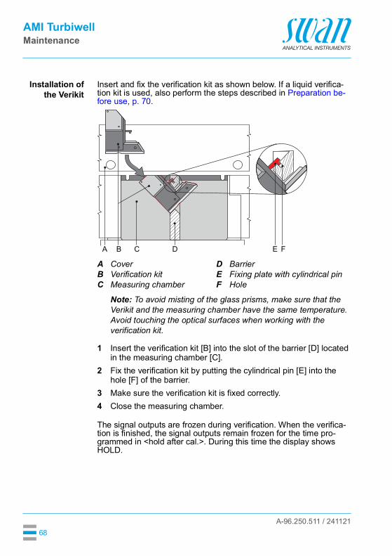
Insert and fix the verification kit as shown below. If a liquid verifica-tion kit is used, also perform the steps described in Preparation be-fore use, p. 70.
Note: To avoid misting of the glass prisms, make sure that the Verikit and the measuring chamber have the same temperature. Avoid touching the optical surfaces when working with the verification kit.
1 Insert the verification kit [B] into the slot of the barrier [D] located in the measuring chamber [C].
2 Fix the verification kit by putting the cylindrical pin [E] into the hole [F] of the barrier.
3 Make sure the verification kit is fixed correctly.4 Close the measuring chamber.
The signal outputs are frozen during verification. When the verifica-tion is finished, the signal outputs remain frozen for the time pro-grammed in <hold after cal.>. During this time the display shows HOLD.
ABC
CoverVerification kitMeasuring chamber
DEF
BarrierFixing plate with cylindrical pinHole
C D E FA B

A-96.250.511 / 241121
AMI TurbiwellMaintenance
69
VerificationKit Turbiwell
Liquid
The Verification Kit Turbiwell Liquid can be filled with any aqueous suspension or emulsion, provided that the suspension or emulsion is compatible with the materials used.
Note: The Verification Kit Turbiwell Liquid is suitable for verification, but not for calibration!
WARNING
Please observe the necessary safety precautions when handling hazardous chemicals. Read the Safety Data Sheets carefully!
Filling To fill the Verification Kit Turbiwell Liquid, proceed as follows:1 Unscrew both screw plugs [A].2 Fill 13.5 to 14 g of the standard into the cuvette through one of
the openings.Note: The cuvette must not be completely filled with liquid, otherwise it may be damaged by overpressure if the temperature rises.
3 Close the cuvette with the two screw plugs.4 Perform the steps specified in Preparation before use, p. 70.5 Perform the matching procedure, see Matching, p. 64.
Housing: PETWindows: PMMAScrew plugs: PVDF
ABC
Screw plugsCuvetteWindow (light beam in)
DE
Window (light beam out)Window (light beam out)
A B DC E

A-96.250.511 / 241121
AMI TurbiwellMaintenance
70
Preparationbefore use
Before inserting the verification kit into the measuring chamber, per-form the following steps:
1 Shake to obtain a homogeneous mixture.2 Place the cuvette as shown below. Tap against the cuvette to let
all air rise to the top.
3 Turn the cuvette counterclockwise.4 Make sure that all air is in position [H]. There must be no air bub-
bles on the windows [C] and [E].
5 Proceed with sections Installation of the Verikit, p. 68 andVerification, p. 67.
Refilling Before filling with a new standard, fill the cuvette with water and shake well to remove all residues. After each refill, the matching pro-cedure (see Matching, p. 64) must be repeated.
F Air bubble G Standard
CE
Window (light beam in)Window (light beam out)
GH
StandardAir bubble
F G
H GC E

A-96.250.511 / 241121
AMI TurbiwellMaintenance
71
Cleaning theVerification Kit
CAUTION
Damage to optical surfacesNever use organic agents i. e. alcohol to clean the optical surfac-es of the verification kit. Use a dry cleaning cloth for lenses to clean the optical surfaces
[A]. If necessary, moisten with demineralized water. If the verification kit is wet, dry it with warm air of max. 50 °C.
Solidverification kit
Solid verification kit: If the verification is still out of range after clean-ing, send the verification kit back to the manufacturer for cleaning and recertification.
Liquidverification kit
AB
Acrylic glass prismsHousing
A
B
AB
Acrylic glass windowsHousing
A
B

A-96.250.511 / 241121
AMI TurbiwellMaintenance
72
6.5.2 Wet VerificationWet verification can be used instead of verification with a Verikit. It is performed with a standard with a known turbidity filled into the mea-suring chamber instead of the sample.
Note: When performing a wet verification do not use a standard below 1 FNU/NTU.
1 Navigate to menu <Maintenance>/<Verification> and press [Enter].
2 Choose <Other method> and press [Enter].
3 Stop sample flow.
4 Open the measuring chamber.5 Open the drain valve if the instru-
ment is not equipped with an auto-matic drain valve.
6 Wait until the measuring chamber is empty.
7 Seal the overflow [E] with the rubber stopper [F].See Seal the overflow, p. 63.
8 Close the drainage valve.9 Fill the measuring chamber with the
standard.10 Close the measuring chamber.11 Press [Enter].
3.1
Matching
Maintenance
Set Time 01.01.05 16:30:00
CalibrationSimulation
Verification
3.1.2VerificationSwan VerikitOther method
3.1.2.5
- Close inlet valve.
- Empty meas. chamber
Other method
- Open meas. chamber- Open drainage valve
<Enter> to continue
3.1.2.5
- Plug drain 1 with aOther method
rubber stopper.
<Enter> to continue
3.1.2.5
- Close Drainage ValveOther method
- Fill with standard- Close meas. chamber
<Enter> to continue

A-96.250.511 / 241121
AMI TurbiwellMaintenance
73
12 Enter the turbidity of the standard as the reference value.
13 Press [Enter].
The verification is running.
14 Press [Enter] to save.
15 Open the drainage valve.16 Empty the measuring chamber.17 Remove the rubber stopper.
18 Close the drainage valve.19 Open the inlet valve.20 Press [Enter] to finish.
3.1.2.5
Reference value 14.0 FNUOther method
<Enter> to continue
Actual value 21.7 FNU
Progress
Reference value 21.6 FNUDeviation 0.1%
3.1.2.5Other method
Actual value 21.7 FNUReference value 21.6 FNUDeviation 0.1%
<Enter> to save
3.1.2.5Other method
- Open Drainage Valve.- Empty meas. chamber.- Remove rubber stopper.
<Enter> to continue
3.1.2.5Other method
- Close Drainage Valve.- Open inlet valve.
<Enter> to finish
3.1.2.5Other method

A-96.250.511 / 241121
AMI TurbiwellMaintenance
74
6.6. Longer Stop of OperationDo not switch off the instrument if your operation is suspended for less than a week. Power consumption is very low and the turbidime-ter remains ready for use.If water hardness is very high, lime deposition may precipitate.
1 Stop sample flow.2 Switch off power.3 Empty measuring chamber by opening the drain valve. (With
automatic drain valve option, select <Maintenance>/<Drainage>/<Manual operation>/<Motor valve>/<open> menu item).
4 If necessary clean the measuring chamber (see Cleaning the Measuring Chamber, p. 56).

A-96.250.511 / 241121
AMI TurbiwellTroubleshooting
75
7. Troubleshooting
7.1. Calibration ErrorsError message: Deviation too big!! Please check manual.
7.2. Matching ErrorsError message: Deviation too big!! Please check manual.
7.3. Verification ErrorsError message: Deviation too big!! Please check manual.
Possible cause Corrective ActionWrong formazine stan-dard.
Check formazine standard. If necessary prepare a new formazine standard, see Prepare the 20 NTU formazine standard, p. 60.
Measuring chamber dirty. Clean measuring chamber, see Cleaning the Measuring Chamber, p. 56.
Possible cause Corrective ActionCalibration Perform a new calibration, see
Calibration, p. 59.Verification kit dirty. Clean the verification kit, see
Calibration, p. 59.
Possible cause Corrective ActionVerification kit dirty. Clean the verification kit, see
Calibration, p. 59.Verification kit reference value.
Perform a new matching, see Matching, p. 64.Check if the correct Verikit is used.
Wrong Verikit in use. Check if the correct Verikit is used.

A-96.250.511 / 241121
AMI TurbiwellTroubleshooting
76
7.4. Error List
Error Non-fatal Error. Indicates an alarm if a programmed value is exceeded.Such Errors are marked E0xx (bold and black).
Fatal Error (blinking symbol)Control of dosing devices is interrupted.The indicated measured values are possibly incorrect.Fatal Errors are divided in the following two categories: Errors which disappear if correct measuring conditions are re-
covered (i.e. Sample Flow low).Such Errors are marked E0xx (bold and orange)
Errors which indicate a hardware failure of the instrument.Such Errors are marked E0xx (bold and red)
Error or fatal ErrorError not yet acknowledged.Check Pending Errors 1.1.5 and take corrective action.
Navigate to <Messages>/<Pending Errors>
Press [ENTER] to acknowledge the Pending Errors.
The Error is reset and saved in the Message List.
12 l/h
HOLD 14:10:45R1
0.04 FNUR2
1.1
Message List
Pending ErrorsMaintenance List
Messages
1.1.5Pending ErrorsError Code E002
Alarm low
<Enter> to Acknowledge

A-96.250.511 / 241121
AMI TurbiwellTroubleshooting
77
Error Description Corrective actionE001 Alarm high – check process
– check programmed value 5.3.1.1.1, p. 97
E002 Alarm low – check process– check programmed value 5.3.1.1.25, p.
97
E005 Range – turbidity out of range– disappears if measuring chamber is
filled
E009 Sample Flow high – check sample flow– check programmed value 5.3.1.2.2, p.
97
E010 Sample Flow low – establish sample flow– clean instrument– check programmed value 5.3.1.2.31, p.
97
E013 Case Temp. high – check case/environment temperature– check programmed value 5.3.1.4, p. 97
E014 Case Temp. low – check case/environment temperature– check programmed value 5.3.1.5, p. 97
E017 Control Timeout – check control device or programming in Installation, Relay contact, Relay 1 & 2 5.3.2 & 5.3.3, p. 97
E018 Turbi disconnected – shut off power– check wiring
E020 Lamp off – close measuring chamber cover
E024 Input active – See If Fault Yes is programmed in Menu 5.3.4, p. 101
E026 IC LM75 – call service
E028 Signal output open – check wiring on signal outputs 1 and 2
E030 EEProm Frontend – call service

A-96.250.511 / 241121
AMI TurbiwellTroubleshooting
78
E031 Calibration Recout – call service
E032 Wrong Frontend – call service
E033 Power-on – none, normal status
E034 Power-down – none, normal status
Error Description Corrective action

A-96.250.511 / 241121
AMI TurbiwellTroubleshooting
79
7.5. Replacing Fuses
WARNING
External Voltage.Externally supplied devices connected to relay 1 or 2 or to the alarm relay can cause electrical shocks Make sure that the devices connected to the following contacts
are disconnected from the power before resuming installation.– relay 1– relay 2– alarm relay
Find and repair the cause for the short circuit before replacing the fuse.Use tweezers or needle-nosed pliers to remove the defective fuse.Use original fuses provided by SWAN only.
A
BCDEFG
AC variant: 1.6 AT/250 V Instrument power supplyDC variant: 3.15 AT/250 V Instrument power supply1.0 AT/250V Relay 11.0 AT/250V Relay 21.0 AT/250V Alarm relay1.0 AF/125V Signal output 21.0 AF/125V Signal output 11.0 AF/125V Signal output 3
A B C D E F G

A-96.250.511 / 241121
AMI TurbiwellProgram Overview
80
8. Program Overview
For explanations about each parameter of the menus see Program List and Explanations, S. 86.
Menu 1 Messages: informs about pending errors and mainte-nance tasks and shows the error history. Password protection possible. No settings can be modified.
Menu 2 Diagnostics: is always accessible for everybody. No password protection. No settings can be modified.
Menu 3 Maintenance: is for service: Calibration, simulation of outputs and set time/date. Please protect with password.
Menu 4 Operation: is for the user, allowing to set limits, alarm values, etc. The presetting is done in the menu Installation (only for the System engineer). Please protect with password.
Menu 5 Installation: Defining assignment of all inputs and out-puts, measuring parameters, interface, passwords, etc. Menu for the system engineer. Password strongly recommended.
8.1. Messages (Main Menu 1)
8.2. Diagnostics (Main Menu 2)
Pending Errors Pending Errors 1.1.5* * Menu numbers1.1*Message List Number 1.2.1*1.2* Date, TimeMaintenance List Maintenance List 1.3.5*1.3*
Identification Designation AMI Turbiwell2.1* Version V6.26-10/21
Version TURBI 1.35Factory Test2.1.4*Operating Time2.1.5*

A-96.250.511 / 241121
AMI TurbiwellProgram Overview
81
Sensors Turbidity Turbidity FNU/NTU * Menu numbers2.2* 2.2.1* (Raw value)
QuotientScale Factor 1Offset FNU/NTU
Miscellaneous Case Temp. 2.2.2.1*2.2.2*History Cal. History Number 2.2.3.1.1*2.2.3* 2.2.3.1* Date, Time
Factor cal.Factor active
Ver. History Number 2.2.3.2.1*2.2.3.2* Date, Time
Verikit #Meas. ValueDeviation
VERI-KIT History Number 2.2.3.3.1*2.2.3.3* Date, Time
Verikit #Assign. ValueMeas. Value
Process Cal. ppm Zero deviation 2.2.3.1* If Dimension ppm2.2.3* Slope is selected
Sample Sample ID 2.3.1*2.3* Sample Flow
delta T 1delta T 1
I/O State Alarm Relay 2.4.1*2.4* Relay 1/2 2.4.2*
InputSignal Output 1/2
Interface Protocol 2.5.1* (only with RS4852.5* Baud rate interface)

A-96.250.511 / 241121
AMI TurbiwellProgram Overview
82
8.3. Maintenance (Main Menu 3)If FNU or NTU is selected as unit:
If ppm is selected as unit:
Regardless of the unit selected:
Verification SWAN VERIKIT # 3.1.1* * Menu numbers3.1* Other Method 3.1.2*Matching Solid Verikit SWAN VERIKIT # 3.2.1.1*3.2* 3.2.1* Follow screen instructions
Liquid Verikit SWAN VERIKIT # 3.2.1.2*3.2.2* Follow screen instructions
Calibration Calibration Progress3.32* 3.32.1*
Process Cal. ppm Detect Zero 3.1.1*3.1* Specify Slope 3.1.2*
Simulation Alarm Relay 3.4.1*3.4* Relay 1 3.4.2*
Relay 2 3.4.3*Signal Output 1 3.4.4*Signal Output 2 3.4.5*
Set Time (Date), (Time)3.5*Drainage Manual operation Motor valve3.6* 3.6.1* 3.6.1.1
Parameters Mode 3.6.2.1*3.6.2* Start Time 3.6.2.2*
Duration 3.6.2.3*Delay 3.6.2.4*Signal outputs 3.6.2.5*Output/Control 3.6.2.6*
Clean meas. chamber3.7*

A-96.250.511 / 241121
AMI TurbiwellProgram Overview
83
8.4. Operation (Main Menu 4)
Sensors Filter Time Const. 4.1.1*4.1* Hold after Cal. 4.1.2*Relay Contacts Alarm Relay Alarm Alarm High 4.2.1.1.1*4.2* 4.2.1* 4.2.1.1* Alarm Low 4.2.1.1.25*
Hysteresis 4.2.1.1.35*Delay 4.2.1.1.45*
Relay 1&2 Setpoint 4.2.x.100*4.2.2* & 4.2.3* Hysteresis 4.2.x.200*
Delay 4.2.x.30*Input Active 4.2.4.1*4.2.4* Signal Outputs 4.2.4.2*
Output / Control 4.2.4.3*Fault 4.2.4.4*Delay 4.2.4.5*
Logger Log Interval 4.3.1*4.3* Clear Logger 4.3.2*

A-96.250.511 / 241121
AMI TurbiwellProgram Overview
84
8.5. Installation (Main Menu 5)
Sensors Sensor type 5.1.1* * Menu numbers5.1* Dimension 5.1.2*
Flow Flow measurement 5.1.3.1*5.1.3* Slope 5.1.3.2*Offset 5.1.4
Signal Outputs Signal Output 1 & 2 Parameter 5.2.1.1 & 5.2.2.1*5.2* 5.2.1* & 5.2.2* Current Loop 5.2.1.2 & 5.2.2.2*
Function 5.2.1.3 & 5.2.2.3*Scaling Range Low 5.2.x.40.10*5.2.x.40 Range High 5.2.x.40.20*
Relay Contacts Alarm Relay Alarm Alarm High 5.3.1.1.1*5.3* 5.3.1* 5.3.1.1* Alarm Low 5.3.1.1.25
Hysteresis 5.3.1.1.35Delay 5.3.1.1.45
Sample Flow Flow Alarm 5.3.1.2.1*5.3.1.2* Alarm High 5.3.1.2.2*
Alarm Low 5.3.1.2.36*Case Temp. high 5.3.1.4*Case Temp. low 5.3.1.5*
Relay 1 & 2 Function 5.3.2.1 & 5.3.3.1*5.3.2* & 5.3.3* Parameter 5.3.2.20 & 5.3.3.20*
Setpoint 5.3.2.300 & 5.3.3.300*Hysteresis 5.3.2.400 & 5.3.3.400*Delay 5.3.2.50 & 5.3.3.50*
Input Active 5.3.4.1*5.3.4* Signal Outputs 5.3.4.2*
Output/Control 5.3.4.3*Fault 5.3.4.4*Delay 5.3.4.5*

A-96.250.511 / 241121
AMI TurbiwellProgram Overview
85
Miscellaneous Language 5.4.1* * Menu numbers5.4* Set defaults 5.4.2*
Load Firmware 5.4.3*Password Messages 5.4.4.1*5.4.4* Maintenance 5.4.4.2*
Operation 5.4.4.3*Installation 5.4.4.4*
Sample ID 5.4.5*Line break detection 5.4.6
Interface Protocol 5.5.1* (only with RS4855.5* Device Address 5.5.21* interface)
Baud Rate 5.5.31*Parity 5.5.41*

A-96.250.511 / 241121
AMI TurbiwellProgram List and Explanations
86
9. Program List and Explanations
1 Messages1.1 Pending Errors
Provides the list of active errors with their status (active, acknowl-edged). If an active error is acknowledged, the alarm relay is active again. Cleared errors are moved to the message list.
1.2 Message ListShows the error history: Error code, date and time of issue, and sta-tus (active, acknowledged, cleared).64 errors are memorized. Then the oldest error is cleared to save the newest error (circular buffer).
1.3 Maintenance ListProvides the list of necessary maintenance. Cleared maintenance messages are moved to the Message list.
2 DiagnosticsIn diagnostics mode, the values can only be viewed, not modified.
2.1 Identification2.1.1 Designation: Designation of the instrument.2.1.2 Version: Firmware of the instrument (e.g. V6.26-10/21).2.1.3 Version TURBI, e.g. 1.35.2.1.4 Factory test: Test date of the instrument, motherboard and front-end
QC test.2.1.5 Operating time: years, days, hours, minutes, seconds.
2.2 Sensors2.2.1 Turbidity:
Turbidity: in FNU/NTU.Raw value: Turbidity in counts.Quotient: Division of detector signal by reference signal.
2.2.2 Miscellaneous2.2.2.1 Case Temp.: Current temperature in °C of electronics housing.

A-96.250.511 / 241121
AMI TurbiwellProgram List and Explanations
87
2.2.3 History2.2.3.1 Cal. History: Only for diagnostic purposes. Review the values of the
last calibrations. Max. 64 data records are memorized.2.2.3.1.1 Number: Calibration counter.
Date, Time: Date and time of the calibration.Factor cal.: Factor of the last calibration.Factor active: Current factor in use for the measurement.
2.2.3.2 Ver. history: Only for diagnostic purposes. Review the values of the last verifications. Max. 64 data records are memorized.
2.2.3.2.1 Number: Verification counter.Date, Time: Date and time of the verification.Verikit #: Name of the verikit.Meas value: The measured value of the verification.Deviation: Shows the deviation in % from the reference value. The reference value is measured and stored during the “Matching”.
2.2.3.3 VERI-KIT History:2.2.3.3.1 Number: Matching counter.
Date, Time: Date and time of the matching.Verikit #: Name of the verikit.Assign. Value: The value on the label of the Verikit which was entered during Matching.Meas. Value: The measured value is stored as reference value for the verification.
2.2.3 Process Cal. ppm2.2.3.1 Zero: 1st calibration point. Background of sample without component
in FNU/NTU.Slope: Factor in FNU, NTU or ppm.
2.3 Sample2.3.1 Sample ID: Shows the identification assigned to a sample. This iden-
tification is defined by the user to identify the location of the sample.Sample flow: Flow in l/h (if Q-Flow or Q-Hflow is selected).If deltaT flow is selected, additionally:deltaT 1: Temperature measured at sample inlet of deltaT sensordeltaT 2: Temperature measured at sample outlet of deltaT sensor
Available if ppm is chosen, see menu 5.1.2, p. 93

A-96.250.511 / 241121
AMI TurbiwellProgram List and Explanations
88
2.4 I/O State2.4.1- 2.4.2 Shows the actual status of all in- and outputs.
2.5 InterfaceOnly available if optional interface is installed. Review programmed communication settings.
3 Maintenance3.1 Verification
3.1.1 SWAN Verikit: Press [Enter] to select the Verikit you need for the ver-ification. Further details see Verification, p. 64.
3.1.2 Other method: Other method is a wet verification with a standard with a known turbidity filled into the measuring chamber instead of the sample. Further details see Wet Verification, p. 72.
3.2 Matching3.2.1 Solid Verikit
3.2.1.1 SWAN Verikit #: Press [Enter] to select the Verikt you want to match or enter a new Verikit for matching. Further details see Matching, p. 64.
3.2.2 Liquid Verikit3.2.2.1 SWAN Verikit #: Press [Enter] to select the Verikt you want to match
or enter a new Verikit for matching. Further details see Matching, p. 64.
3.3 Calibration
3.32.5 Calibration: After selecting Calibration press [Enter] and follow the in-structions on the screen. Further details see Calibration, p. 59
Alarm Relay: Active or inactiveRelay 1 and 2: Active or inactiveInput: Open or closedSignal Output 1 and 2: Actual current in mASignal Output 3: if option is installed
Available if FNU or NTU is chosen, see menu 5.1.2, p. 93.

A-96.250.511 / 241121
AMI TurbiwellProgram List and Explanations
89
3.4 SimulationTo simulate a value or a relay state, select the alarm relay, relay 1 and 2 signal output 1 and 2
with the [ ] or [ ] key.Press the <Enter> key.Change the value or state of the selected item with the [ ] or [ ] key. Press the <Enter> key.
The value is simulated by the relay/signal output.
At the absence of any key activities, the instrument will switch back to normal mode after 20 min. If you quit the menu, all simulated val-ues will be reset.
3.5 Set TimeAdjust date and time.
3.6 DrainageThe following settings are only valid for instruments equipped with an automated drain valve (auto-drain).
3.6.1 Manual operation3.6.1.1 Motor valve: Opening or closing of the drain valve.
Note: Manual operation can be used anytime regardless of the draining mode selected in menu 3.6.2.1. During a manually started draining cycle the following applies:• The measurement is continued normally and alarms are
issued.• The signal outputs are set to "Hold" and the controller outputs
to "Off". The settings under 3.6.2.5 and 3.6.2.6 do not apply.
3.6.2 Parameters3.6.2.1 Mode: possible modes are: interval, daily, weekly, off, Input, Field-
bus.
Alarm Relay: Active or inactiveRelay 1 and 2: Active or inactiveSignal Output 1 and 2: Actual current in mASignal Output 3: If option is installed actual current in mA

A-96.250.511 / 241121
AMI TurbiwellProgram List and Explanations
90
3.6.1.20 Interval: The draining interval can be programmed within a range of 1–23 h.
3.6.2.3 Duration: Enter the duration of the draining valve being opened. Range: 5–300 sec.
3.6.2.4 Delay: During duration plus the delay time the signal and control out-puts are held in the operating mode.Range: 0–1’800 sec.
3.6.2.5 Signal Outputs: Select operating mode of the signal output:
3.6.2.6 Output/Control: Select operating mode of the controller output:
The start of a draining cycle can be set to any time of day.3.6.1.21 Start time: to set the start time proceed as follows:
1 Press [Enter], to set the hours.2 Set the hour with the [ ] or [ ] keys.3 Press [Enter], to set the minutes.4 Set the minutes with the [ ] or [ ] keys.5 Press [Enter], to set the seconds.6 Set the seconds with the [ ] or [ ] keys.Range: 00:00:00–23:59:59
3.6.2.3 Duration: see Interval3.6.2.4 Delay: see Interval3.6.2.5 Signal Outputs: see interval.3.6.2.6 Output/Control: see interval.
The start of a draining cycle can be programmed for one or more days of the week. The programmed start time is valid for all selected days.
3.6.2.1 Interval
Hold: Signal outputs hold the last valid measured value.Measurement is interrupted. Errors, except fatal errors, are not issued.
Off: Signal outputs are switched off (set to 0 or 4 mA).Errors, except fatal errors, are not issued.
Hold: Controller continues based on the last valid value.Off: Controller is switched off.
3.6.2.1 daily
3.6.2.1 weekly

A-96.250.511 / 241121
AMI TurbiwellProgram List and Explanations
91
3.6.2.22 Calendar:3.6.2.22.1 Start time: The programmed start time is valid for each of the pro-
grammed days.3.6.2.22.2 Monday: Possible settings, on or off
to3.6.2.22.8 Sunday: Possible settings, on or off
3.6.2.3 Duration: see Interval3.6.2.4 Delay: see Interval3.6.2.5 Signal Outputs: see interval.3.6.2.6 Output/Control: see interval.
The automatic draining is switched off.
The draining is controlled via input.3.6.2.3 Duration: see Interval3.6.2.4 Delay: see Interval3.6.2.5 Signal Outputs: see interval.3.6.2.6 Output/Control: see interval.
The draining is controlled via Fieldbus.3.6.2.3 Duration: see Interval3.6.2.4 Delay: see Interval3.6.2.5 Signal Outputs: see interval.3.6.2.6 Output/Control: see interval.
3.7 Clean meas. chamberCounts down 1200 seconds in which the measuring chamber can be inspected and cleaned.During this time, no turbidity or flow alarms are issued. The mea-sured value is kept at the last valid value and the relays are frozen. If programmed, the controller continues based on the last valid value.The routine can be terminated at any time by pressing [Enter]. The counter can be restarted by pressing an arrow key.
Note: Before exiting the routine or before the 1200 seconds have elapsed, completely fill and close the measuring chamber and open the flow regulating valve.
3.6.2.1 Off
3.6.2.1 Input
3.6.2.1 Fieldbus

A-96.250.511 / 241121
AMI TurbiwellProgram List and Explanations
92
3.1 Process Cal. ppm
3.1.1 Detect Zero: 1st calibration point. Determination of the zero point in a sample without component to be calibrated.
3.1.2 Specify Slope: 2nd calibration point. A sample with known concentra-tion of component to be calibrated is used to determine the slope.Range: 0.0–999.9 ppm
Note: See chapter ppm Calculation, e.g. “Oil in water”, p. 48 for further details.
4 Operation4.1 Sensors
4.1.1 Filter time constant: Used to damp noisy signals. The higher the filter time constant, the slower the system reacts to changes of the mea-sured value. Range: 5–300 sec
4.1.2 Hold after cal: To allow the instrument to stabilize again after calibra-tion. During cal. and hold time the signal outputs are frozen, alarms and limits are not active. Range: 0–6000 sec
4.2 Relay ContactsSee chapter 5 Installation.
4.3 LoggerThe instrument is equipped with an internal logger. The logger data can be copied to a PC with an USB stick if option USB interface is installed.The logger can save approx. 1500 data records. Records consists of: Date, time, alarms, measured value, flow, raw value, signal, refer-ence, case temperature.
4.3.1 Log Interval: Select a convenient log interval. Consult the table be-low to estimate the max logging time. When the login buffer is full, the oldest data record is erased to make room for the newest one. (circular buffer).
4.3.2 Clear logger: If confirmed with yes, all data is erased and a new data series is started.
Available if ppm is chosen, see menu 5.1.2, p. 93
Interval 1 s 5 s 1 min 5 min 10 min 30 min 1 h
Time 25 min 2 h 25 h 5 d 10 d 31 d 62 d

A-96.250.511 / 241121
AMI TurbiwellProgram List and Explanations
93
5 Installation5.1 Sensors
5.1.1 Sensor type: Display of the used sensor type (e.g. Well IR)5.1.2 Dimension: Choose the measurement unit (FNU, NTU or ppm)5.1.3 Flow: Select a flow measurement method.
5.1.3.1 Flow measurement: Select the type of flow sensor if a flow sensor is installed. Possible flow sensors:
5.3.1.2 Slope: Only available if deltaT flow has been selected. Increase or decrease the slope to adjust the sample flow, see Adjusting the del-taT Flow Sensor (Option), p. 46.
5.1.4 Offset: A manual offset of the measured value can be set.Range: -1.000 to +1.000 FNU/NTU
5.2 Signal OutputsNote: The navigation in the menu <Signal Output 1> and <Signal Output 2> is equal. For reason of simplicity only the menu numbers of Signal Output 1 are used in the following.
5.2.1 & 5.2.2 Signal Output 1 & 2: Assign process value, the current loop range and a function to each signal output.
5.2.1.1 Parameter: Assign one of the process values to the signal output.Available values: Meas. value, Sample flow.
5.2.1.2 Current Loop: Select the current range of the signal output.Make sure the connected device works with the same current range.Available ranges: 0–20 [mA] or 4–20 [mA]
5.2.1.3 Function: Define if the signal output is used to transmit a process value or to drive a control unit. Available functions are: Linear, bilinear or logarithmic for process values.
See As process values, p. 94 Control upwards or control downwards for controllers.
See As control output, p. 95
Flow measurement Q-Flow / Q-HFlow deltaTNoneQ-FlowQ-HFlowdeltaT

A-96.250.511 / 241121
AMI TurbiwellProgram List and Explanations
94
As processvalues
The process value can be represented in 3 ways: linear, bilinear or logarithmic. See graphs below.
5.2.1.40 Scaling: Enter beginning and end point (Range low & high) of the linear or logarithmic scale. In addition, the midpoint for the bilinear scale.
Parameter Meas. value5.2.1.40.10 Range low: 0.000 FNU/NTU5.2.1.40.20 Range high: 250 FNU/NTU
Parameter Sample Flow5.2.1.40.11 Range low: 0.0 l /h5.2.1.40.21 Range high: 100.0 l /h
AB
linearbilinear
X Measured value
X Measured value (logarithmic)
20
0.0 0.1 0.2 0.3 0.4 0.5
10 12
(0 -
20 [m
A])
0 / 4
(4 -
20 [m
A])
[mA]
X
AB
20
10 1 2 3 4
10 100 1’000 10’000
10 12
(0 -
20 [m
A])
0 / 442 6
(4 -
20 [m
A])
[mA]
X

A-96.250.511 / 241121
AMI TurbiwellProgram List and Explanations
95
As controloutput
Signal outputs can be used for driving control units. We distinguish different kinds of controls: P-controller: The controller action is proportional to the devia-
tion from the setpoint. The controller is characterized by the P-Band. In the steady-state, the setpoint will never be reached. The deviation is called steady-state error.Parameters: setpoint, P-Band
PI-controller: The combination of a P-controller with anI-controller will minimize the steady-state error. If the reset time is set to zero, the I-controller is switched off.Parameters: setpoint, P-Band, reset time.
PD-controller: The combination of a P-controller with a D-controller will minimize the response time to a fast change of the process value. If the derivative time is set to zero, the D-controller is switched off.Parameters: setpoint, P-Band, derivative time.
PID-controller: The combination of a P-, an I - and a D-control-ler allows a proper control of the process.Parameters: setpoint, P-Band, reset time, derivative time.
Ziegler-Nichols method for the optimization of a PID controller:Parameters: Setpoint, P-Band, Reset time, Derivative time, Control Timeout
The point of intersection of the tangent with the respective axis will result in the parameters a and L.Consult the manual of the control unit for connecting and program-ming details. Choose control upwards or downwards.
ABX
Response to maximum control outputTangent on the inflection pointTime
XpTnTv
= 1.2/a= 2L= L/2
X
Y
B A
L
a

A-96.250.511 / 241121
AMI TurbiwellProgram List and Explanations
96
Control upwards or downwards5.2.1.43 Control Parameters: Meas. value
5.2.1.43.10 Setpoint: User-defined process value (Measured value or flow)Range: 0–250 FNU/NTU
5.2.1.43.20 P-Band: Range below (upwards control) or above (downwards control) the set-point, within the dosing intensity is reduced from 100% to 0% to reach the set-point without overshooting.Range: 0–250 FNU/NTU
5.2.1.43 Control Parameters: Sample flow5.2.1.43.11 Setpoint: User-defined process value (Measured value or flow)
Range: 0–100.0 l/h5.2.1.43.21 P-Band: Range below (upwards control) or above (downwards
control) the set-point, within the dosing intensity is reduced from 100% to 0% to reach the set-point without overshooting.Range: 0–100.0 l/h
5.2.1.43.3 Reset time: The reset time is the time till the step response of a single I-controller will reach the same value as it will be suddenly reached by a P-controller.Range: 0–9’000 sec
5.2.1.43.4 Derivative time: The derivative time is the time till the ramp response of a single P-controller will reach the same value as it will be suddenly reached by a D-controller.Range: 0–9’000 sec
5.2.1.43.5 Control timeout: If a controller action (dosing intensity) is constantly over 90% during a defined period of time and the process value does not come closer to the setpoint, the dosing process will be stopped for safety reasons.Range: 0–720 min
5.3 Relay Contacts5.3.1 Alarm Relay: The alarm relay is used as cumulative error indicator.
Under normal operating conditions the contact is active.The contact is inactive at: power loss detection of system faults like defective sensors or electronic
parts high case temperature lack of reagents process values out of programmed ranges.
Program alarm levels, hysteresis values and delay times for the following parameters:Meas. value, Sample Flow

A-96.250.511 / 241121
AMI TurbiwellProgram List and Explanations
97
5.3.1.1 Alarm5.3.1.1.1 Alarm High: If the measured value rises above the alarm high value,
the alarm relay is activated and E001, is displayed in the message list. Range: 0–250 FNU/NTU
5.3.1.1.25 Alarm Low: If the measured value falls below the alarm low value, the alarm relay is activated and E002 is displayed in the message list.Range: 0–250 FNU/NTU
5.3.1.1.35 Hysteresis: Within the hyst. range, the relay does not switch. This prevents damage of relays contacts when the measured value fluctuates around the alarm value.Range. 0–250 FNU/NTU
5.3.1.1.45 Delay: Duration, the activation of the alarm relay is retarded after the measured value has risen above/fallen below the programmed alarm.Range: 0–28‘800 Sec
5.3.1.2 Sample Flow: Define at which sample flow a flow alarm should be issued.
5.3.1.2.1 Flow Alarm: Program if the alarm relay should be activated if there is a flow alarm. Choose between yes or no. The flow alarm will always be indicated in the display, pending error list, saved in the message list and the logger.Available values: Yes or no
Note: Sufficient flow is essential for a correct measurement.We recommend to program yes.
5.3.1.2.2 Alarm High: If the measured values rises above the programmed value E009 will be issued.Range: 0–100 l/h
5.3.1.2.31 Alarm Low: If the measured values falls below the programmed value E010 will be issued.Range: 0–100 l/h
5.3.1.4 Case Temp. high: Set the alarm high value for temperature of electronics housing. If the value rises above the programmed value E013 is issued.Range: 40–75 °C
5.3.1.5 Case Temp. low: Set the alarm low value for temperature of electronics housing. If the value falls below the programmed value E014 is issued.Range: -10 to +10 °C
5.3.2 & 5.3.3 Relay 1 and 2: The contacts can be set as normally open or normal-ly closed with a jumper. See Relay 1 and 2, p. 41.The function of relay contacts 1 and 2 is defined by the user.

A-96.250.511 / 241121
AMI TurbiwellProgram List and Explanations
98
Note: The navigation in the menu <Relay 1> and <Relay 2> is equal. For reason of simplicity only the menu numbers of Relay 1 are used in the following.
1 First select the functions as:- Limit upper/lower, - Control upwards/downwards, - Timer- Fieldbus,
2 Then enter the necessary data depending on the selected func-tion.
When the relays are used as upper or lower limit switches, program the following:
5.3.2.20 Parameter: select a process valueAvailable values: Meas. value, Sample flow.
5.3.2.300 Setpoint: If the measured value rises above respectively falls below the set-point, the relay is activated.Range: 0–250 FNU/NTU
5.3.2.400 Hysteresis: within the hysteresis range, the relay does not switch. This prevents damage of relay contacts when the measured value fluctuates around the alarm value.Range: 0–250 FNU/NTU
5.3.2.50 Delay: Duration, the activation of the alarm relay is retarded after the measured value has risen above/fallen below the programmed alarm.Range. 0–7200 Sec
The relays may be used to drive control units such as solenoid valves, membrane dosing pumps or motor valves. When driving a motor valve both relays are needed, relay 1 to open and relay 2 to close the valve.
5.3.2.22 Parameter: select a process value (Meas. value)5.3.2.32 Choose the respective actuator:
Time proportional Frequency Motor valve
Examples of metering devices that are driven time proportional are solenoid valves, peristaltic pumps.Dosing is controlled by the operating time.
5.3.2.1 Function = Limit upper/lower:
5.3.2.1 Function = Control upwards/downwards:
Actuator = Time proportional

A-96.250.511 / 241121
AMI TurbiwellProgram List and Explanations
99
5.3.2.32.20 Cycle time: duration of one control cycle (on/off change).Range: 0–600 sec.
5.3.2.32.30 Response time: Minimal time the metering device needs to react. Range: 0–240 sec.
5.3.2.32.4 Control Parameters:Range for each Parameter same as 5.2.1.43, p. 96
Examples of metering devices that are pulse frequency driven are the classic membrane pumps with a potential free triggering input. Dosing is controlled by the repetition speed of dosing shots.
5.3.2.32.21 Pulse frequency: Max. pulses per minute the device is able to re-spond to. Range: 20–300/min.
5.3.2.32.31 Control Parameters:Range for each Parameter same as 5.2.1.43, p. 96
Dosing is controlled by the position of a motor driven mixing valve.5.3.2.32.22 Run time: Time needed to open a completely closed valve
Range: 5–300 Sec.5.3.2.32.32 Neutral zone: Minimal response time in % of the runtime. If the re-
quested dosing output is smaller than the response time, no change will take place.Range: 1–20 %
5.3.2.32.4 Control Parameters:Range for each Parameter same as 5.2.1.43, p. 96
The relay will be activated repetitively depending on the programmed time scheme.
5.3.2.24 Mode: Operating mode (interval, daily, weekly)
5.3.2.340 Interval: The interval can be programmed within a rangeof 1–1’440 min.
5.3.2.44 Run Time: Enter the time the relay stays active.Range: 5–32’400 Sec.
5.3.2.54 Delay: during run time plus the delay time the signal and control out-puts are held in the operating mode programmed below.Range: 0–6’000 Sec.
Actuator = Frequency
Actuator = Motor valve
5.3.2.1 Function = Timer:
5.3.2.24 Interval

A-96.250.511 / 241121
AMI TurbiwellProgram List and Explanations
100
5.3.2.6 Signal Outputs: Select operating mode of the signal output:
5.3.2.7 Output/Control: Select operating mode of the controller output:
The relay contact can be activated daily, at any time of a day.5.3.2.341 Start time: to set the start time proceed as follows:
1 Press [Enter], to set the hours.2 Set the hour with the [ ] or [ ] keys.3 Press [Enter], to set the minutes.4 Set the minutes with the [ ] or [ ] keys.5 Press [Enter], to set the seconds.6 Set the seconds with the [ ] or [ ] keys.
Range: 00:00:00–23:59:595.3.2.44 Run Time: see Interval5.3.2.54 Delay: see Interval5.3.2.6 Signal Outputs: see Interval5.3.2.7 Output/Control: see Interval
The relay contact can be activated at one or several days, of a week. The daily starting time is valid for all days.
5.3.2.342 Calendar:5.3.2.342.1 Start time: The programmed start time is valid for each of the pro-
grammed days. To set the start time see 5.3.2.341, p. 100.Range: 00:00:00–23:59:59
Cont.: Signal outputs continue to issue the measured value.Hold: Signal outputs hold the last valid measured value.
Measurement is interrupted. Errors, except fatal errors, are not issued.
Off: Signal outputs are switched off (set to 0 or 4 mA).Errors, except fatal errors, are not issued.
Cont.: Controller continues normally.Hold: Controller continues based on the last valid value.Off: Controller is switched off.
5.3.2.24 daily
5.3.2.24 weekly

A-96.250.511 / 241121
AMI TurbiwellProgram List and Explanations
101
5.3.2.342.2 Monday: Possible settings, on or offto
5.3.2.342.8 Sunday: Possible settings, on or off5.3.2.44 Run Time: see Interval5.3.2.54 Delay: see Interval5.3.2.6 Signal Outputs: see Interval5.3.2.7 Output/Control: see Interval
The relay will be switched via the Profibus input. No further parame-ters are needed.
5.3.4 Input: The functions of the relays and signal outputs can be defined depending on the position of the input contact, i.e. no function, closed or open.
5.3.4.1 Active: Define when the input should be active:
5.3.4.2 Signal Outputs: Select the operation mode of the signal outputs when the relay is active:
5.3.4.3 Output/Control: (relay or signal output):
5.3.4.4 Fault:
5.3.2.1 Function = Fieldbus
No: Input is never active.When closed Input is active if the input relay is closedWhen open: Input is active if the input relay is open
Continuous: Signal outputs continue to issue the measured value.
Hold: Signal outputs hold the last valid measured value.Measurement is interrupted. Errors, except fatal errors, are not issued.
Off: Set to 0 or 4 [mA] respectively. Errors, except fatal errors, are not issued.
Continuous: Controller continues normally.Hold: Controller continues based on the last valid value.Off: Controller is switched off.
No: No message is issued in pending error list and the alarm relay does not close when input is active. Message E024 is stored in the message list.
Yes: Message E024 is issued and stored in the message list. The Alarm relay closes when input is active.

A-96.250.511 / 241121
AMI TurbiwellProgram List and Explanations
102
5.3.4.5 Delay: Time which the instrument waits, after the input is deactivated, before returning to normal operation.Range: 0–6‘000 Sec
5.4 Miscellaneous5.4.1 Language: Set the desired language.
Available settings: German/English/French/Spanish5.4.2 Set defaults: Reset the instrument to factory default values in three
different ways: Calibration: Sets calibration values back to default. All other
values are kept in memory. In parts: Communication parameters are kept in memory. All
other values are set back to default values. Completely: Sets back all values including communication pa-
rameters. All matched Verikits are deleted.5.4.3 Load Firmware: Firmware updates should be done by instructed
service personnel only.5.4.4 Password: Select a password different from 0000 to prevent
unauthorized access to the menus “Messages”, “Maintenance”, “Operation” and “Installation”.Each menu may be protected by a different password.If you forgot the passwords, contact the closest SWAN representative.
5.4.5 Sample ID: Identify the process value with any meaning full text, such as KKS number.
5.4.6 Line Break Detection: Define if message E028 should be issued in case of a line break on signal output 1 or 2.Choose between <Yes> or <No>.

A-96.250.511 / 241121
AMI TurbiwellProgram List and Explanations
103
5.5 InterfaceSelect one of the following communication protocols. Depending on your selection, different parameters must be defined.
5.5.1 Protocol: Profibus5.5.20 Device address: Range: 0–1265.5.30 ID-Nr.: Range: Analyzer; Manufacturer; Multivariable5.5.40 Local operation: Range: Enabled, Disabled
5.5.1 Protocol: Modbus RTU5.5.21 Device address: Range: 0–1265.5.31 Baud rate: Range: 1200–115 200 Baud5.5.41 Parity: Range: none, even, odd
5.5.1 Protocol: USB stickOnly visible if an USB interface is installed. No further settings are possible.
5.5.1 Protocol: HARTDevice address: Range: 0–63

A-96.250.511 / 241121
AMI TurbiwellDefault Values
104
10. Default Values
OperationSensors Filter Time Const.: ........................................................................30 s
Hold after Cal.:............................................................................300 sAlarm Relay .........................................................................same as in InstallationRelay 1 & 2 .........................................................................same as in Installation
Input .........................................................................same as in InstallationLogger Logger Interval:........................................................................ 30 min
Clear Logger:.................................................................................. no
InstallationSensor Dimension:...................................................................................FNU
Flow; Flow measurement: ..........................................................NoneSignal Output
1 & 2Parameter:.......................................................................Meas. valueCurrent loop:........................................................................4 –20 mAFunction:.....................................................................................linearScaling: Range low:...................................................... 0.0 FNU/NTUScaling: Range high: .................................................. 10.0 FNU/NTU
Alarm Relay Alarm high: .................................................................. 200 FNU/NTUAlarm low:................................................................. 0.000 FNU/NTUHysteresis:..................................................................... 10 FNU/NTUDelay: .............................................................................................5 sSample Flow: Flow Alarm: .............................................................yesSample Flow: Alarm High: ...................................................... 40.0 l /hSample Flow: Alarm Low: ......................................................... 6.0 l/hCase temp. high: ....................................................................... 65 °CCase temp. low:........................................................................... 0 °C
Relay 1 & 2 Function:............................................................................. limit upperParameter:.......................................................................Meas. valueSetpoint: ......................................................................100 FNU/NTUHysteresis:.................................................................. 5.00 FNU/NTUDelay: .............................................................................................5 sIf Function = Control upw. or dnw:Parameter: Meas. valueSettings: Actuator: Frequency
Settings: Pulse Frequency: .................................................120/minSettings: Control Parameters: Setpoint:................... 100 FNU/NTUSettings: Control Parameters: P-band: ................... 5.00 FNU/NTUSettings: Control Parameters: Reset time:..................................0 s

A-96.250.511 / 241121
AMI TurbiwellDefault Values
105
Settings: Control Parameters: Derivative Time: ......................... 0 sSettings: Control Parameters: Control Timeout:..................... 0 min
Settings: Actuator:................................................... Time proportionalCycle time: ............................................................................... 60 sResponse time: ....................................................................... 10 s
Settings: Actuator............................................................. Motor valveRun time: ................................................................................. 60 sNeutral zone: ............................................................................. 5%
If Function = Timer:Mode:...................................................................................... Interval
Interval:................................................................................... 1 minMode: ..........................................................................................daily
Start time: .......................................................................... 00.00.00Mode:....................................................................................... weekly
Calendar; Start time: ......................................................... 00.00.00Calendar; Monday to Sunday:.................................................... Off
Run time: ..................................................................................... 10 sDelay:............................................................................................. 5 sSignal output:............................................................................... contOutput/Control: ............................................................................ cont
Input Active .............................................................................. when closedSignal Outputs ............................................................................. holdOutput/Control ................................................................................ offFault................................................................................................ noDelay............................................................................................ 10 s
Miscellaneous Language:............................................................................... EnglishSet default:...................................................................................... noLoad firmware: ................................................................................ noPassword: ..............................................................for all modes 0000Sample ID: ..........................................................................- - - - - - - -Line break detection ....................................................................... no

AMI TurbiwellIndex
A-96.250.511 / 241121106
11. Index
AAlarm Relay . . . . . . . . . . . . 9, 38Application . . . . . . . . . . . . . . . 8Available Models . . . . . . . . . . . 8
CCable thicknesses . . . . . . . . . . . 34Calendar . . . . . . . . . . . . . . . . 98Calibration . . . . . . . . . . . . . . . 11Changing values. . . . . . . . . . . . 52clean the degasser . . . . . . . . . . 56clean the sample chamber . . . . . . 54Cleaning Module
Calendar. . . . . . . . . . . . . . 89Configurations and Options . . . . . 8
DData logger . . . . . . . . . . . . . . . 90Default Values . . . . . . . . . . . . 102Degasser . . . . . . . . . . . . . . . . 21Dimensions. . . . . . . . . . . . . . . 14Display . . . . . . . . . . . . . . . . . 50
EElectrical wiring . . . . . . . . . . . . 18Error List . . . . . . . . . . . . . . . . 74
FFilter time constant . . . . . . . . . . 90formazine standard . . . . . . . 57–58
HHART . . . . . . . . . . . . . . . . . . 43
IInput . . . . . . . . . . . . . . . . . 9, 38
Instrument Setup . . . . . . . . . . . 18Interface . . . . . . . . . . . . . . . . 41
HART . . . . . . . . . . . . . . . 43Modbus . . . . . . . . . . . . . . 42Profibus. . . . . . . . . . . . . . 42USB . . . . . . . . . . . . . . . . 43
MMeasuring Principle . . . . . . . . . 10Modbus . . . . . . . . . . . . . . . . 42Mounting requirements . . . . . . . 19
NNephelometric system . . . . . . . . 10
OOn-site requirements. . . . . . 12, 18
PPower Supply . . . . . . . . . . 12, 37Power-up . . . . . . . . . . . . . . . 18Profibus . . . . . . . . . . . . . . . . 43Program Access . . . . . . . . . . . 49
Rre-calibration . . . . . . . . . . . . . 57Relay . . . . . . . . . . . . . . . . . . . 8Relay Contacts . . . . . . . . . . . . 90Relay status . . . . . . . . . . . . . . 50Run-in period . . . . . . . . . . . . . 18
SSample and waste
basic connection. . . . . . . . . 31with degasser . . . . . . . . . . 33with deltaT sensor. . . . . . . . 32

AMI TurbiwellIndex
A-96.250.511 / 241121107
Sample inlet . . . . . . . . . . . . . . 31Sample requirements . . . . . . . . 12Sensors . . . . . . . . . . . . . . . . 90Signal Outputs . . . . . . . . . . 8, 41
TTerminals . . . . . . . . 36, 38–39, 42Turbidimeter Specifications . . . . . 13
UUSB Interface . . . . . . . . . . . . . 43
VVerification . . . . . . . . . . . . 11, 18verification kit. . . . . . . . . . . . . . 66
WWire . . . . . . . . . . . . . . . . . . . 34

A-96.250.511 / 241121
AMI TurbiwellNotes
108
12. Notes

A-96.250.511 / 241121
AMI TurbiwellNotes
109

AMI Turbiwell
A-96.250.511 / 241121
Pot
able
Wat
er
Phar
mac
eutic
al W
a et r
Water Steam Cycles
C terHig
ooling Wa
h Purity Water
Waste
tW
aer & Ef uents
Pool &
Sanitary
Swan Analytical Instruments ∙ CH-8340 Hinwil www.swan.ch ∙ [email protected]
Swan Products - Analytical Instruments for:
Swan is represented worldwide by subsidiary companies and distributors and cooperates with independent representatives all over the world. For contact in-formation, please scan the QR code.