a 3-rrrs parallel structure for measuring robot … · a 3-rrrs parallel structure for measuring...
TRANSCRIPT
A 3-RRRS PARALLEL STRUCTURE FOR MEASURING ROBOT PATH
Glicerinho Danter Lopes Soares Júnior, [email protected] João Carlos Mendes Carvalho, e-mail, [email protected] Rogério Sales Gonçalves, [email protected] UFU, Universidade Federal de Uberlândia, Curso de Engenharia Mecatrônica, Campus Santa Mônica, Bairro Santa Mônica, CEP 38400-902, Uberlândia, Minas Gerais Abstract. Multibody systems consist on a kinematic chain composed of links that can be rigid or flexible, interconnected by joints. The multibody systems are of great importance and are used in various applications such as in aerospace and automotive, machine tools, mechanisms, sea exploration, medicine and robotics. A robotic structure can be defined as a multibody system. Despite the research carried, there is still no system capable of verifying the trajectory described by its end-effector, during its evolution in the workspace. This paper attempts to develop an electro-mechanical system using as the base the parallel structure 3-RRRS, where the passive revolute joints are coupled to potentiometers, whose signals are acquired by a data acquisition board, connected to a computer. These signals are properly processed and converted, through the geometric model of parallel structure 3-RRRS, in the position and orientation of the mobile platform. This mobile platform can be connected to the end-effector robot to verify the robot path, comparing the position and orientation commanded to the robot with those obtained by the measurement structure 3-RRRS. Thus, in this paper are presented the direct geometric models, the Jacobian matrix, analysis of geometric errors, the influence of each revolute joint errors on the quality of measurement and data acquisition. Finally experimental tests are conducted in a commercial measurement three-dimensional structure. Keywords: Multibody Systems, Robotic Structures, 3-RRRS Parallel Structure, Measure.
1. INTRODUCTION
Robotic structures may be defined as multibody systems, composed of segments, rigid or flexible, interconnected by
joints. Multibody systems can be classified as serial kinematic chain, in which segments are connected in series one by one from the base to the end-effector, parallel kinematic chain, in which exist two or more serial kinematic chains connecting the base to the end-effector, and hybrid kinematic chain, which is the combination of the above (Tsai, 1999; Gonçalves, 2009).
Robotic structures have many applications in various fields such as aviation, maritime exploration, medical and automotive. Few literature studies describe equipment for verification of robot trajectories. Oliveira and Carvalho (2002) perform the measurement of robot path with a modified parallel structure based on Stewart platform to realize the indirect measurement of position and orientation. Several other studies apply the measure of displacement, but in systems with micro-positioning. Fan and Chen (1999) developed a system to measure micro-displacement employing four laser Doppler scales and two quadrant photo detectors to detect the positions and the rotations of an optical reflection device. Wu and Chuang (2004) developed a compact roll angular displacement measurement system based on measuring the phase difference between the reference and measurement lasers beams. Kim et al. (2002) use a six degree-of-freedom (d.o.f.) displacement measurement system using detection of the movement of rays reflected from various cooperative targets that relies upon optical triangulation and optical beam deflection method. Other works show applications to measure only rotation, like Zangl et al. (2007), that propose the study on the use of an array of lateral hall elements for the implementation of a three-axial Joystick, that can measure rotation about one axis and measure or detect positions of the tilt along the remaining horizontal axes.
In this way, this paper proposes the development of an electromechanical system using the parallel structure 3-RRRS able to perform measurements of paths providing the position and orientation of the moving platform or end-effector.
2. 3-RRRS PARALLEL STRUCTURE
The parallel structure 3-RRRS has a triangular base and a triangular moving platform. Connecting the base vertices
and the moving platform vertices are RRRS serial chains (from a passive revolute joint at the base, the segments are connected serially by two other passive revolute joints and connected to the end-effector by a spherical joint), Fig. 1(a). In this first model, all structure was assembled using parts from the kit Lego Mindstorm NXT. The use of these parts is justified by its tolerance manufacturing, ensuring dimensional homogeneity of the elements, and easy of assembly, besides the low weight of the parts. The Lego pieces flexibility was neglected. The sketch of the 3-RRRS structure is shown in Fig. 1 (a) and layout of the structure built with pieces of kit Lego is shown in Fig. 1 (b). X, Y and Z are the axes of the inertial frame at the origin O fixed at the base center and x, y and z are the axes of frame at the origin A fixed at the moving platform center, Ai are the vertices of the moving platform in which the leg i is connected, dj represents the length of the segment posterior joint j and the notation ij represents the j-th joint of i-th leg.
ABCM Symposium Series in Mechatronics - Vol. 5 Copyright © 2012 by ABCM
Section VII - Robotics Page 988

(a) (b)
Figure 1. a) Sketch of 3-RRRS structure; b) 3-RRRS structure assembled with pieces of kit Lego.
By moving the mobile platform of the structure 3-RRRS variations occur in the angles of joints, using potentiometers attached to each passive revolute joint, Fig. 1 (b), can be measured these angles and, from the direct geometric model, to obtain the position and orientation of the moving platform.
2.1. Angles measurement system
The read of the each passive revolute joint angles of 3-RRRS was realized indirectly through read the voltage in the
potentiometers coupled in the passive revolute joints, were used precision potentiometers Baotou 3590S-103, 10kΩ - 10 turns in series with a 390Ω resistor, connected with a source model HP 6653A 50V/30A. The read voltage was performed by a data acquisition card NI USB-6211 16 bit - 250kS/s and LabView software to interface with the data acquisition card and the signal processing. The configuration series of the potentiometer with the resistor increases significantly the system sensitivity in the desired range. Figure 2 shows the voltage on the potentiometer by its resistance, using the 390Ω resistor and can be noted that in the half of the first lap of the potentiometer the voltage reaches 56% of the voltage provided by the source, making more precise measurements and minimizing the effects of external noise on the signal.
Figure 2. Voltage on the potentiometer by its resistance The calibration of the potentiometers was done during the assembly of the structure, after each potentiometer being
coupled to its respective passive revolute joint. With a protractor with 1 degree resolution, was done the calibration of the potentiometer, with an increase of one degree along your angle work, using the data acquisition card NI USB-6211.
After the acquisition, through the LabView software, the signal passes through a low pass filter 2nd order Butterworth, implemented digitally, and is converted from voltage to degrees using the equation of the series circuit. The program allows save the desired number of measurement and using Matlab software from the direct geometric model implemented is possible obtain the moving platform position and orientation.
ABCM Symposium Series in Mechatronics - Vol. 5 Copyright © 2012 by ABCM
Section VII - Robotics Page 989

2.2. Forward geometric model of 3-RRRS structure
From the structure configuration, i.e. the angles of each passive revolute joint, is possible determine the moving
platform position and orientation using Homogeneous Transformation Matrices (HTM). The sequence of linear transformations performed from the inertial frame in a serial chain structure (leg) to a vertex
of the moving platform is shown in Fig. 3. Where xij, yij and zij represent generalizations of the linear transformations that occurred in the change of inertial frame to the joint j of leg i, the notation “ ´ ” means a change in the orientation of reference; qij represents the angle of joint j of leg i and xi, yi and zi indicate the orientation of the vertex Ai.
Figure 3. Linear transformations from the inertial frame to the moving platform. Equation (1) presents the transformations to perform the change of inertial frame to the point Ai, as shown in Fig. 3.
풑풂 = 풑
푐 푞푠 푞
00
– 푠 푞푐 푞
00
0010
0001
1000
0100
0010
00푑1
1000
00−10
0100
0001
푐 푞푠 푞
00
– 푠 푞푐 푞
00
0010
0001
1000
0100
0010
푑001
푐 푞푠 푞
00
– 푠 푞푐 푞
00
0010
0001
1000
0100
0010
푑001
(1)
Where pai is a HTM that contains the position and orientation of the vertex i of the moving platform, pi1 represents
the HTM of inertial frame to the reference in the joint i1, c and s represent the cosine and sine, respectively, of the angles qij and rb is the radius of base. Equation (2) shows the HTM to the vertices of the base, the joints 1 of the legs 1, 2 and 3.
풑 =
1000
0100
0010
0푟푏01
, 풑 =
1000
0100
0010
– 푟푏 푠 120º푟푏 푐 120º
01
e 풑 =
1000
0100
0010
−푟푏 푠−120º푟푏 푐 −120º
01
(2)
From the position of the vertices of the end-effector, given by HTM pa1, pa2 and pa3, and the condition that the
reference moving platform is located at the center of triangular platform is possible obtain the position of the moving platform pa, Eq (3).
풑풂 =1 0 00 1 00 0 1
000∗ 풑풂 풑풂 풑풂 ∗
0001
(3)
Equation (4) provides the y axis, located in the reference fixed at the moving platform center, from the condition of
that it points to the vertex A1.
ABCM Symposium Series in Mechatronics - Vol. 5 Copyright © 2012 by ABCM
Section VII - Robotics Page 990
풚 = 풑풂 풑풂
‖풑풂 풑풂‖ (4)
Equation (5) gives the x axis from the condition of that it is parallel to segment 풑풂 풑풂 . 풙 = 풑풂 풑풂
‖풑풂 풑풂 ‖ (5)
Equation (6) gives the z axis perpendicular to the axes x and y. 풛 = 풙 x 풚 (6) The orientation matrix of the moving platform, Ra, is composed by the orientation of the axes of reference attached
to the moving platform, Eq (7). 푹풂 = [풙 풚 풛] (7) The matrix containing the position and orientation of the end-effector, pA, is the combination of the matrix of
orientation Ra and of the position vector pa, Eq (8). 풑푨 = 푹풂 풑풂
0 1 (8)
Similarly to the direct geometric model, the inverse geometric model was obtained using HTM.
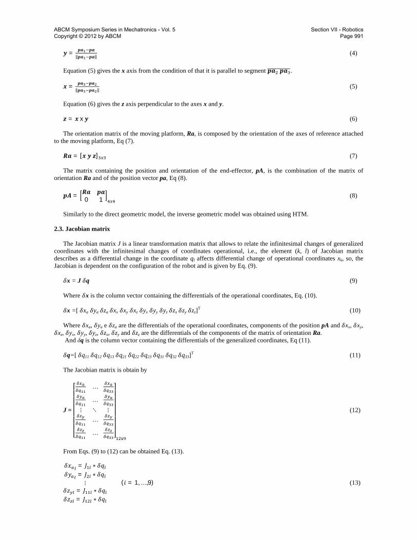
2.3. Jacobian matrix The Jacobian matrix J is a linear transformation matrix that allows to relate the infinitesimal changes of generalized
coordinates with the infinitesimal changes of coordinates operational, i.e., the element (k, l) of Jacobian matrix describes as a differential change in the coordinate ql affects differential change of operational coordinates xk, so, the Jacobian is dependent on the configuration of the robot and is given by Eq. (9).
훿x = J 훿q (9) Where 훿x is the column vector containing the differentials of the operational coordinates, Eq. (10). 훿x =[ 훿xa 훿ya 훿za 훿xx 훿xy 훿xz 훿yx 훿yy 훿yz 훿zx 훿zy 훿zz]T (10) Where 훿xa, 훿ya e 훿za are the differentials of the operational coordinates, components of the position pA and 훿xx, 훿xy,
훿xz, 훿yx, 훿yy, 훿yz, 훿zx, 훿zy and 훿zz are the differentials of the components of the matrix of orientation Ra. And δq is the column vector containing the differentials of the generalized coordinates, Eq (11). 훿q=[ 훿q11 훿q12 훿q13 훿q21 훿q22 훿q23 훿q31 훿q32 훿q33]T (11) The Jacobian matrix is obtain by
J =
⎣⎢⎢⎢⎢⎢⎢⎡ …
…⋮ ⋱ ⋮
…
… ⎦⎥⎥⎥⎥⎥⎥⎤
(12)
From Eqs. (9) to (12) can be obtained Eq. (13). 훿푥 = 퐽 ∗ 훿푞훿푦 = 퐽 ∗ 훿푞
⋮훿푧 = 퐽 ∗ 훿푞훿푧 = 퐽 ∗ 훿푞
(푖 = 1, … ,9) (13)
ABCM Symposium Series in Mechatronics - Vol. 5 Copyright © 2012 by ABCM
Section VII - Robotics Page 991
That can calculate the contribution of error due to l-th joint. Thus, the position geometric error in the read of the
vector pA due to l-th joint, epl, is given by Eq. (14). 푒 = (훿푥 ) + (훿푦 ) + (훿푧 ) = 훿푞 ∗ 퐽 + 퐽 + 퐽 = 훿푞 ∗ 휇 (14) Where the parameter µpl represents the index of position sensitivity due to the l-th joint. The absolute error in measuring the position, according to Alves (1996), is given by Eq. (15). 푒 = (훿푥) + (훿푦) + (훿푧) = (푥 − 푥 ) + (푦 − 푦 ) + (푧 − 푧 ) (15) Where xa, ya and za are the default values and x’a, y’a and z’a are values of position achieved by the structure in a
known configuration. Similar to the position geometric error, the contribution of orientation geometric error due to l-th joint, eol, is given
by Eq. (16).
푒 = (훿푥 ) + 훿푥 + ⋯+ 훿푧 + (훿푧 ) = 훿푞 ∗ 퐽 + ⋯+ 퐽 = 훿푞 ∗ 휇 (16) And the absolute error on measurement of the orientation is given by Eq. (17).
푒 = (푥 ′ − 푥 ) + 푥 ′ − 푥 + ⋯+ 푧 ′ − 푧 + (푧 ′ − 푧 ) (17) The Jacobian matrix of the 3-RRRS structure was solved using the Matlab software.
2.3. Analysis of geometric errors Known equations of the forward geometric model the estimation of the errors present in the position and orientation
of the vector pA, assuming that the structure is rigid were carried out. To determine the errors introduced by the mechanical structure and the signal acquisition system was used a
computer model, where two values are obtained, one corresponding to a path inside the workspace of the structure in a configuration set to true and another value with an estimated error inserted computationally.
The error analysis was performed using an error value estimated from the components of the measurement system. The potentiometers used, due the calibration, have resolution of 1º; to the acquisition system, oscillations of 1mV in the signal acquired of the potentiometers, due to external noise, cause variations of up to 0.25 °, depending on the angle at which be in the potentiometer. To perform the analysis of geometric errors was used an error of 1º in each passive revolute joint.
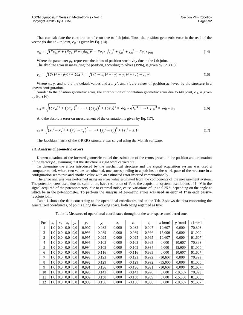
Table 1 shows the data concerning to the operational coordinates and in the Tab. 2 shows the data concerning the generalized coordinates, of points along the working space, both being regarded as true.
Table 1. Measures of operational coordinates throughout the workspace considered true.
Pos. xx xy xz yx yy yz zx zy zz x [mm] y [mm] z [mm]
1 1,0 0,0 0,0 0,0 0,997 0,082 0,000 -0,082 0,997 10,607 0,000 70,393 2 1,0 0,0 0,0 0,0 0,996 0,089 0,000 -0,089 0,996 15,000 0,000 81,000 3 1,0 0,0 0,0 0,0 0,995 0,095 0,000 -0,095 0,995 10,607 0,000 91,607 4 1,0 0,0 0,0 0,0 0,995 0,102 0,000 -0,102 0,995 0,000 10,607 70,393 5 1,0 0,0 0,0 0,0 0,994 0,109 0,000 -0,109 0,994 0,000 15,000 81,000 6 1,0 0,0 0,0 0,0 0,993 0,116 0,000 -0,116 0,993 0,000 10,607 91,607 7 1,0 0,0 0,0 0,0 0,992 0,123 0,000 -0,123 0,992 -10,607 0,000 70,393 8 1,0 0,0 0,0 0,0 0,992 0,129 0,000 -0,129 0,992 -15,000 0,000 81,000 9 1,0 0,0 0,0 0,0 0,991 0,136 0,000 -0,136 0,991 -10,607 0,000 91,607 10 1,0 0,0 0,0 0,0 0,990 0,143 0,000 -0,143 0,990 0,000 -10,607 70,393 11 1,0 0,0 0,0 0,0 0,989 0,150 0,000 -0,150 0,989 0,000 -15,000 81,000 12 1,0 0,0 0,0 0,0 0,988 0,156 0,000 -0,156 0,988 0,000 -10,607 91,607
ABCM Symposium Series in Mechatronics - Vol. 5 Copyright © 2012 by ABCM
Section VII - Robotics Page 992

Table 2. Measures of generalized coordinates throughout the workspace considered true.
Pos. q11 [°] q12 [°] q13 [°] q21 [°] q22 [°] q23 [°] q31 [°] q32 [°] q33 [°]
1 279,78 -7,32 -59,88 25,73 -9,98 -41,24 144,17 -0,65 -83,19 2 283,70 -23,29 -36,08 24,28 -32,43 0,00 141,15 -12,96 -74,41 3 279,78 -44,58 0,00 25,75 -39,33 0,00 144,15 -27,78 -47,14 4 270,00 -4,61 -81,48 37,88 -6,45 -52,14 142,12 -6,45 -52,14 5 270,00 -17,47 -72,20 40,72 -27,88 -14,17 139,28 -27,88 -14,17 6 270,00 -33,61 -39,74 37,89 -40,61 0,00 142,11 -40,61 0,00 7 260,23 -8,62 -58,14 35,88 -0,07 -83,73 154,23 -9,32 -42,05 8 256,32 -25,16 -32,82 38,90 -12,36 -75,14 155,68 -32,15 0,00 9 260,24 -44,98 0,00 35,90 -27,03 -48,30 154,21 -39,08 0,00 10 270,00 -19,26 -24,67 20,82 -0,65 -76,24 159,18 -0,65 -76,24 11 270,00 -34,26 0,00 16,59 -13,14 -63,97 163,41 -13,14 -63,97 12 270,00 -41,06 0,00 20,85 -29,07 -37,73 159,15 -29,07 -37,73
Similar to the Tabs. 1 and 2, Tabs. 3 and 4 present the data concerning the operational and generalized coordinates,
respectively, of points throughout the workspace, with the errors inserted.
Table 3. Measures of operational coordinates throughout the workspace with inserted error.
Pos. xx xy xz yx yy yz zx zy zz x [mm] y [mm] z [mm] 1 1,0 0,0 0,0 0,0 0,991 0,131 -0,001 -0,131 0,990 10,294 0,616 70,174 2 1,0 0,0 0,0 0,0 0,990 0,135 -0,001 -0,135 0,990 14,727 0,746 80,791 3 1,0 0,0 0,0 0,0 0,990 0,134 0,000 -0,134 0,990 10,295 0,917 91,381 4 1,0 0,0 0,0 0,0 0,988 0,152 0,000 -0,152 0,988 -0,296 11,299 70,175 5 1,0 0,0 0,0 0,0 0,988 0,156 0,000 -0,156 0,988 -0,269 15,899 80,820 6 1,0 0,0 0,0 0,0 0,987 0,157 0,000 -0,157 0,987 -0,294 11,635 91,448 7 1,0 0,0 0,0 0,0 0,985 0,171 0,002 -0,171 0,985 -11,008 0,742 70,172 8 1,0 0,0 0,0 0,0 0,985 0,173 0,001 -0,173 0,985 -15,439 0,925 80,786 9 1,0 0,0 0,0 0,0 0,984 0,174 0,001 -0,174 0,985 -11,006 1,039 91,379 10 1,0 0,0 0,0 0,0 0,981 0,190 0,000 -0,190 0,981 -0,419 -9,903 70,154 11 1,0 0,0 0,0 0,0 0,980 0,193 0,000 -0,193 0,980 -0,444 -14,187 80,755 12 1,0 0,0 0,0 0,0 0,980 0,197 0,000 -0,197 0,980 -0,418 -9,693 91,401
Table 4. Measures of generalized coordinates throughout the workspace with inserted error.
Pos. q11 [°] q12 [°] q13 [°] q21 [°] q22 [°] q23 [°] q31 [°] q32 [°] q33 [°]
1 278,785 -8,32 -58,88 26,73 -8,98 -42,24 143,17 0,35 -84,19 2 282,703 -24,29 -35,08 25,28 -31,43 -1,00 140,15 -11,96 -75,41 3 278,78 -45,58 1,00 26,75 -38,33 -1,00 143,15 -26,78 -48,14 4 269 -5,61 -80,48 38,88 -5,45 -53,14 141,12 -5,45 -53,14 5 269 -18,47 -71,20 41,72 -26,88 -15,17 138,28 -26,88 -15,17 6 269 -34,61 -38,74 38,89 -39,61 -1,00 141,11 -39,61 -1,00 7 259,231 -9,62 -57,14 36,88 0,93 -84,73 153,23 -8,32 -43,05 8 255,32 -26,16 -31,82 39,90 -11,36 -76,14 154,68 -31,15 -1,00 9 259,238 -45,98 1,00 36,90 -26,03 -49,30 153,21 -38,08 -1,00 10 269 -20,26 -23,67 21,82 0,35 -77,24 158,18 0,35 -77,24 11 269 -35,26 1,00 17,59 -12,14 -64,97 162,41 -12,14 -64,97 12 269 -42,06 1,00 21,85 -28,07 -38,73 158,15 -28,07 -38,73
From Equation (14) and the data of Tabs. 1 to 4 is possible estimate the geometric errors epl and the sensitivity index
µpl that the structure shows when get a read of position in the workspace. The geometric errors and the index of sensitivity due to the passive revolute joints are shown in Tab. 5.
ABCM Symposium Series in Mechatronics - Vol. 5 Copyright © 2012 by ABCM
Section VII - Robotics Page 993
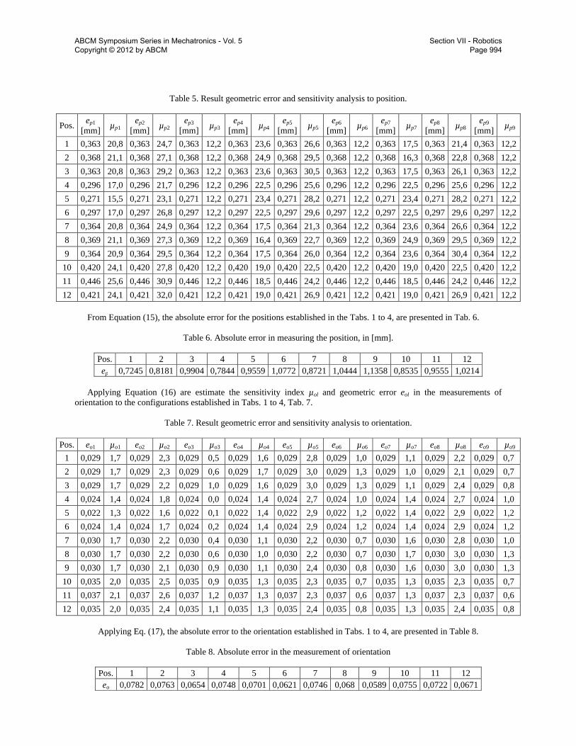
Table 5. Result geometric error and sensitivity analysis to position.
Pos. ep1 [mm] µp1
ep2 [mm] µp2
ep3 [mm] µp3
ep4 [mm] µp4
ep5 [mm] µp5
ep6 [mm] µp6
ep7 [mm] µp7
ep8 [mm] µp8
ep9 [mm] µp9
1 0,363 20,8 0,363 24,7 0,363 12,2 0,363 23,6 0,363 26,6 0,363 12,2 0,363 17,5 0,363 21,4 0,363 12,2 2 0,368 21,1 0,368 27,1 0,368 12,2 0,368 24,9 0,368 29,5 0,368 12,2 0,368 16,3 0,368 22,8 0,368 12,2 3 0,363 20,8 0,363 29,2 0,363 12,2 0,363 23,6 0,363 30,5 0,363 12,2 0,363 17,5 0,363 26,1 0,363 12,2 4 0,296 17,0 0,296 21,7 0,296 12,2 0,296 22,5 0,296 25,6 0,296 12,2 0,296 22,5 0,296 25,6 0,296 12,2 5 0,271 15,5 0,271 23,1 0,271 12,2 0,271 23,4 0,271 28,2 0,271 12,2 0,271 23,4 0,271 28,2 0,271 12,2 6 0,297 17,0 0,297 26,8 0,297 12,2 0,297 22,5 0,297 29,6 0,297 12,2 0,297 22,5 0,297 29,6 0,297 12,2 7 0,364 20,8 0,364 24,9 0,364 12,2 0,364 17,5 0,364 21,3 0,364 12,2 0,364 23,6 0,364 26,6 0,364 12,2 8 0,369 21,1 0,369 27,3 0,369 12,2 0,369 16,4 0,369 22,7 0,369 12,2 0,369 24,9 0,369 29,5 0,369 12,2 9 0,364 20,9 0,364 29,5 0,364 12,2 0,364 17,5 0,364 26,0 0,364 12,2 0,364 23,6 0,364 30,4 0,364 12,2 10 0,420 24,1 0,420 27,8 0,420 12,2 0,420 19,0 0,420 22,5 0,420 12,2 0,420 19,0 0,420 22,5 0,420 12,2 11 0,446 25,6 0,446 30,9 0,446 12,2 0,446 18,5 0,446 24,2 0,446 12,2 0,446 18,5 0,446 24,2 0,446 12,2 12 0,421 24,1 0,421 32,0 0,421 12,2 0,421 19,0 0,421 26,9 0,421 12,2 0,421 19,0 0,421 26,9 0,421 12,2
From Equation (15), the absolute error for the positions established in the Tabs. 1 to 4, are presented in Tab. 6.
Table 6. Absolute error in measuring the position, in [mm].
Pos. 1 2 3 4 5 6 7 8 9 10 11 12 ep 0,7245 0,8181 0,9904 0,7844 0,9559 1,0772 0,8721 1,0444 1,1358 0,8535 0,9555 1,0214
Applying Equation (16) are estimate the sensitivity index µol and geometric error eol in the measurements of
orientation to the configurations established in Tabs. 1 to 4, Tab. 7.
Table 7. Result geometric error and sensitivity analysis to orientation.
Pos. eo1 µo1 eo2 µo2 eo3 µo3 eo4 µo4 eo5 µo5 eo6 µo6 eo7 µo7 eo8 µo8 eo9 µo9 1 0,029 1,7 0,029 2,3 0,029 0,5 0,029 1,6 0,029 2,8 0,029 1,0 0,029 1,1 0,029 2,2 0,029 0,7 2 0,029 1,7 0,029 2,3 0,029 0,6 0,029 1,7 0,029 3,0 0,029 1,3 0,029 1,0 0,029 2,1 0,029 0,7 3 0,029 1,7 0,029 2,2 0,029 1,0 0,029 1,6 0,029 3,0 0,029 1,3 0,029 1,1 0,029 2,4 0,029 0,8 4 0,024 1,4 0,024 1,8 0,024 0,0 0,024 1,4 0,024 2,7 0,024 1,0 0,024 1,4 0,024 2,7 0,024 1,0 5 0,022 1,3 0,022 1,6 0,022 0,1 0,022 1,4 0,022 2,9 0,022 1,2 0,022 1,4 0,022 2,9 0,022 1,2 6 0,024 1,4 0,024 1,7 0,024 0,2 0,024 1,4 0,024 2,9 0,024 1,2 0,024 1,4 0,024 2,9 0,024 1,2 7 0,030 1,7 0,030 2,2 0,030 0,4 0,030 1,1 0,030 2,2 0,030 0,7 0,030 1,6 0,030 2,8 0,030 1,0 8 0,030 1,7 0,030 2,2 0,030 0,6 0,030 1,0 0,030 2,2 0,030 0,7 0,030 1,7 0,030 3,0 0,030 1,3 9 0,030 1,7 0,030 2,1 0,030 0,9 0,030 1,1 0,030 2,4 0,030 0,8 0,030 1,6 0,030 3,0 0,030 1,3 10 0,035 2,0 0,035 2,5 0,035 0,9 0,035 1,3 0,035 2,3 0,035 0,7 0,035 1,3 0,035 2,3 0,035 0,7 11 0,037 2,1 0,037 2,6 0,037 1,2 0,037 1,3 0,037 2,3 0,037 0,6 0,037 1,3 0,037 2,3 0,037 0,6 12 0,035 2,0 0,035 2,4 0,035 1,1 0,035 1,3 0,035 2,4 0,035 0,8 0,035 1,3 0,035 2,4 0,035 0,8
Applying Eq. (17), the absolute error to the orientation established in Tabs. 1 to 4, are presented in Table 8.
Table 8. Absolute error in the measurement of orientation
Pos. 1 2 3 4 5 6 7 8 9 10 11 12 eo 0,0782 0,0763 0,0654 0,0748 0,0701 0,0621 0,0746 0,068 0,0589 0,0755 0,0722 0,0671
ABCM Symposium Series in Mechatronics - Vol. 5 Copyright © 2012 by ABCM
Section VII - Robotics Page 994
From the analysis of the sensitivity index in both the measurements of position and orientation, Tabs 5 and 7, it is
clear that the second joint in all legs, the joint i2, are those that most influence the quality measures and the third joint in all legs, the joint i3, are the least influences.
Based the error analysis the proposed structure 3-RRRS can be used to measure the displacements of trajectories to order of centimeters with maximum error of 1,1358mm, Tab. 6.
The absolute errors in orientation measurements should be analyzed carefully, since they indicate errors in the vector orientation of the coordinate axes of the end-effector of the 3-RRRS structure, so, small errors imply significant angular displacement. After checking through MatLab software of the rotation axis, it was found that the error in the orientation of the moving platform to the settings established by Tabs. 1 to 4, reached 4º.
3. EXPERIMENTAL TEST OF 3-RRRS STRUCTURE
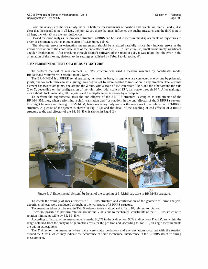
To perform the test of measurement 3-RRRS structure was used a measure machine by coordinates model
BR-M443M Mitutoyo with resolution of 0,5µm. The BR-M443M is a PPPRR serial structure, i.e., from its base, its segments are connected one by one by prismatic
joints, one for each Cartesian axis, giving three degrees of freedom, related to translation in any direction. The terminal element has two rotate joints, one around the Z axis, with a scale of 15º, can rotate 360 °, and the other around the axis X or Y, depending on the configuration of the joint prior, with scale of 15 º, can rotate through 90 °. After making a move should lock, manually, all the joints and the displacement is shown by a computer.
To perform the experimental tests the end-effector of the 3-RRRS structure is coupled to end-effector of the BR-M443M, thus, when performing a shift, translation and / or rotation, in the end-effector of the 3-RRRS structure, this might be measured through BR-M443M, being necessary only transfer the measures to the referential of 3-RRRS structure. A picture of the system is shown in Fig. 6 (a) and the detail of the coupling of end-effector of 3-RRRS structure to the end-effector of the BR-M443M is shown in Fig. 6 (b).
(a) (b)
Figure 6. a) Experimental System; b) Detail of the coupling of 3-RRRS structure to BR-M433 structure. To check the validity of measurements of 3-RRRS structure and confirmation of the geometrical error analysis,
experimental tests were conducted throughout the workspace of 3-RRRS structure. The measures taken can be seen in Tab. 9, referent to translation, and in Tab. 10, referent to rotation. It was not possible to perform rotation around the Y axis due to mechanical constraints of the 3-RRRS structure to
rotation minima possible by BR-M443M. According to Tab. 9, of the measurements made, 96,7% in the X direction, 90% in directions Y and Z, are within the
range obtained from the analysis of geometric errors for the position and, according to Tab. 10, all angle measurements are within expectations.
The Y direction has measures where there were major deviations and any deviations occurred with the rotation around the X axis, which may indicate the occurrence of some mechanical interference in the 3-RRRS structure during measurement.
ABCM Symposium Series in Mechatronics - Vol. 5 Copyright © 2012 by ABCM
Section VII - Robotics Page 995
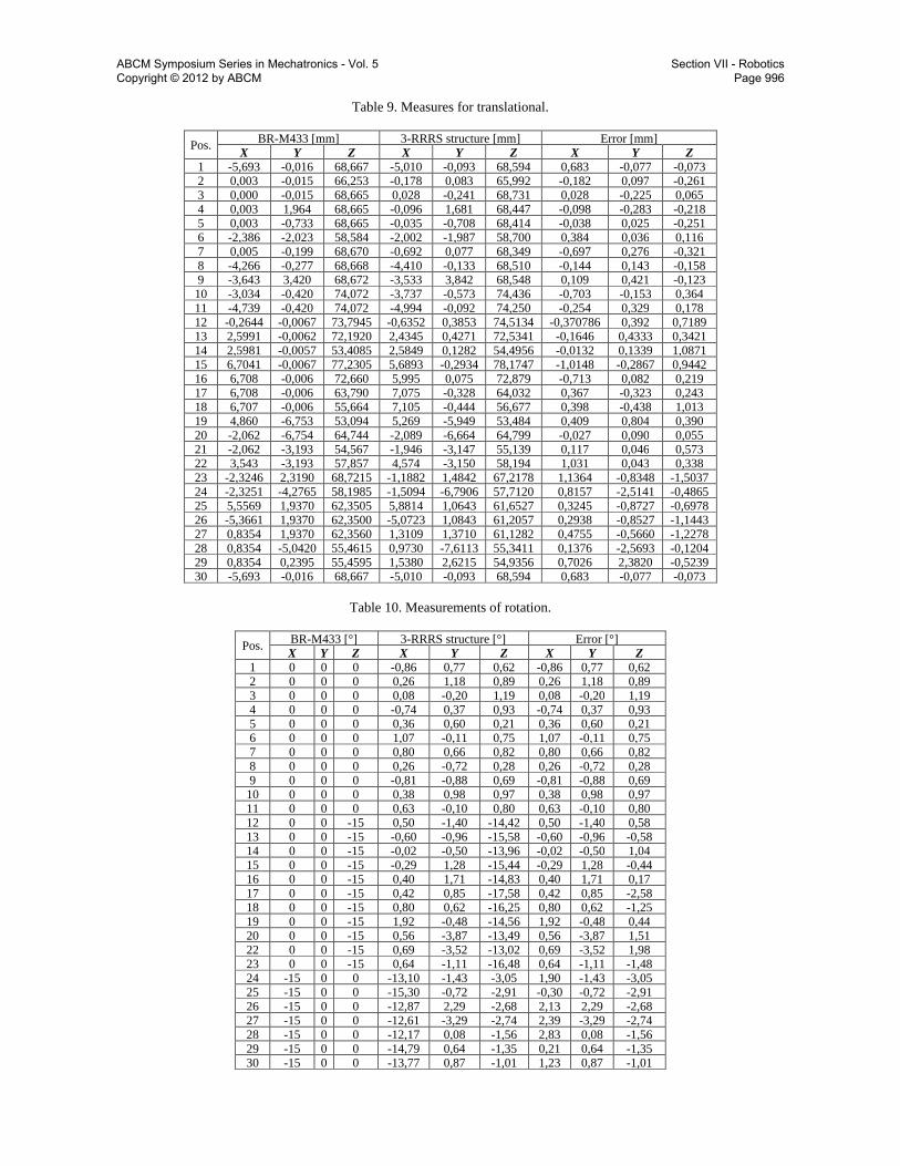
Table 9. Measures for translational.
Pos. BR-M433 [mm] 3-RRRS structure [mm] Error [mm]
X Y Z X Y Z X Y Z 1 -5,693 -0,016 68,667 -5,010 -0,093 68,594 0,683 -0,077 -0,073 2 0,003 -0,015 66,253 -0,178 0,083 65,992 -0,182 0,097 -0,261 3 0,000 -0,015 68,665 0,028 -0,241 68,731 0,028 -0,225 0,065 4 0,003 1,964 68,665 -0,096 1,681 68,447 -0,098 -0,283 -0,218 5 0,003 -0,733 68,665 -0,035 -0,708 68,414 -0,038 0,025 -0,251 6 -2,386 -2,023 58,584 -2,002 -1,987 58,700 0,384 0,036 0,116 7 0,005 -0,199 68,670 -0,692 0,077 68,349 -0,697 0,276 -0,321 8 -4,266 -0,277 68,668 -4,410 -0,133 68,510 -0,144 0,143 -0,158 9 -3,643 3,420 68,672 -3,533 3,842 68,548 0,109 0,421 -0,123 10 -3,034 -0,420 74,072 -3,737 -0,573 74,436 -0,703 -0,153 0,364 11 -4,739 -0,420 74,072 -4,994 -0,092 74,250 -0,254 0,329 0,178 12 -0,2644 -0,0067 73,7945 -0,6352 0,3853 74,5134 -0,370786 0,392 0,7189 13 2,5991 -0,0062 72,1920 2,4345 0,4271 72,5341 -0,1646 0,4333 0,3421 14 2,5981 -0,0057 53,4085 2,5849 0,1282 54,4956 -0,0132 0,1339 1,0871 15 6,7041 -0,0067 77,2305 5,6893 -0,2934 78,1747 -1,0148 -0,2867 0,9442 16 6,708 -0,006 72,660 5,995 0,075 72,879 -0,713 0,082 0,219 17 6,708 -0,006 63,790 7,075 -0,328 64,032 0,367 -0,323 0,243 18 6,707 -0,006 55,664 7,105 -0,444 56,677 0,398 -0,438 1,013 19 4,860 -6,753 53,094 5,269 -5,949 53,484 0,409 0,804 0,390 20 -2,062 -6,754 64,744 -2,089 -6,664 64,799 -0,027 0,090 0,055 21 -2,062 -3,193 54,567 -1,946 -3,147 55,139 0,117 0,046 0,573 22 3,543 -3,193 57,857 4,574 -3,150 58,194 1,031 0,043 0,338 23 -2,3246 2,3190 68,7215 -1,1882 1,4842 67,2178 1,1364 -0,8348 -1,5037 24 -2,3251 -4,2765 58,1985 -1,5094 -6,7906 57,7120 0,8157 -2,5141 -0,4865 25 5,5569 1,9370 62,3505 5,8814 1,0643 61,6527 0,3245 -0,8727 -0,6978 26 -5,3661 1,9370 62,3500 -5,0723 1,0843 61,2057 0,2938 -0,8527 -1,1443 27 0,8354 1,9370 62,3560 1,3109 1,3710 61,1282 0,4755 -0,5660 -1,2278 28 0,8354 -5,0420 55,4615 0,9730 -7,6113 55,3411 0,1376 -2,5693 -0,1204 29 0,8354 0,2395 55,4595 1,5380 2,6215 54,9356 0,7026 2,3820 -0,5239 30 -5,693 -0,016 68,667 -5,010 -0,093 68,594 0,683 -0,077 -0,073
Table 10. Measurements of rotation.
Pos. BR-M433 [°] 3-RRRS structure [°] Error [°]
X Y Z X Y Z X Y Z 1 0 0 0 -0,86 0,77 0,62 -0,86 0,77 0,62 2 0 0 0 0,26 1,18 0,89 0,26 1,18 0,89 3 0 0 0 0,08 -0,20 1,19 0,08 -0,20 1,19 4 0 0 0 -0,74 0,37 0,93 -0,74 0,37 0,93 5 0 0 0 0,36 0,60 0,21 0,36 0,60 0,21 6 0 0 0 1,07 -0,11 0,75 1,07 -0,11 0,75 7 0 0 0 0,80 0,66 0,82 0,80 0,66 0,82 8 0 0 0 0,26 -0,72 0,28 0,26 -0,72 0,28 9 0 0 0 -0,81 -0,88 0,69 -0,81 -0,88 0,69
10 0 0 0 0,38 0,98 0,97 0,38 0,98 0,97 11 0 0 0 0,63 -0,10 0,80 0,63 -0,10 0,80 12 0 0 -15 0,50 -1,40 -14,42 0,50 -1,40 0,58 13 0 0 -15 -0,60 -0,96 -15,58 -0,60 -0,96 -0,58 14 0 0 -15 -0,02 -0,50 -13,96 -0,02 -0,50 1,04 15 0 0 -15 -0,29 1,28 -15,44 -0,29 1,28 -0,44 16 0 0 -15 0,40 1,71 -14,83 0,40 1,71 0,17 17 0 0 -15 0,42 0,85 -17,58 0,42 0,85 -2,58 18 0 0 -15 0,80 0,62 -16,25 0,80 0,62 -1,25 19 0 0 -15 1,92 -0,48 -14,56 1,92 -0,48 0,44 20 0 0 -15 0,56 -3,87 -13,49 0,56 -3,87 1,51 22 0 0 -15 0,69 -3,52 -13,02 0,69 -3,52 1,98 23 0 0 -15 0,64 -1,11 -16,48 0,64 -1,11 -1,48 24 -15 0 0 -13,10 -1,43 -3,05 1,90 -1,43 -3,05 25 -15 0 0 -15,30 -0,72 -2,91 -0,30 -0,72 -2,91 26 -15 0 0 -12,87 2,29 -2,68 2,13 2,29 -2,68 27 -15 0 0 -12,61 -3,29 -2,74 2,39 -3,29 -2,74 28 -15 0 0 -12,17 0,08 -1,56 2,83 0,08 -1,56 29 -15 0 0 -14,79 0,64 -1,35 0,21 0,64 -1,35 30 -15 0 0 -13,77 0,87 -1,01 1,23 0,87 -1,01
ABCM Symposium Series in Mechatronics - Vol. 5 Copyright © 2012 by ABCM
Section VII - Robotics Page 996
4. CONCLUSION
In this paper was developed an electro-mechanical system using as the base the parallel structure 3-RRRS for
measuring robot path. First the structure proposed to measuring robot path was presented. After the geometric model, Jacobian matrix and
the analysis of geometric errors were performed. The experimental tests were realized using a measure machine by coordinates model BR-M443M Mitutoyo with
resolution of 0,5µm. The results show, that according to the analysis of errors and the components used, the proposed structure can be used to verify the position and orientation of a trajectory defined by a given robotic structure.
For future works will be carried out tests on an industrial robot with 6 degrees of freedom and the construction of an improved structure with the use of more accurate sensors.
5. ACKNOWLEDGEMENTS
The authors are thankful to Dimensional Metrology Laboratory of UFU/FEMEC, CNPq, CAPES and FAPEMIG for the partial financing support of this research work.
6. REFERENCES
Alves, A. S. , 1996, “Metrologia Geométrica”, Lisboa, Fundação Calouste Gulbenkian, 269 p. Kim, J.-A., Bae, E. W., Kim, S. H. and Kwak, Y. K., 2002, “Design methods for six-degree-of-freedom displacement
measurement systems using cooperative targets”, Journal of the International Societies for Precision Engineering and Nanotechnology, Vol. 26, pp. 99-104.
Fan, K.-C. and Chen, M.-J., 2000, “A 6-degree-of-freedom measurement system for the accuracy of X-Y stages”, Journal of Elsevier Science Inc., Precision Engineering, Vol. 24, pp. 15-23.
Gonçalves, R. S., 2009, "Estudo de rigidez de cadeias cinemáticas fechadas”, Thesis, Federal University of Uberlândia, Brazil.
Oliveira Jr., A. A. and Carvalho, J. C. M., 2002, “A Modified Stewart Platform for Measuring Robot Path”, MUSME 2002, The International Symposium On Multibody System and Mechatronics, Mexico.
Tsai, L.W., 1999, “Robot Analysis: The Mechanics of Serial and Parallel Manipulators”, John Wiley & Sons, New York, pp.260-297.
Zangl, H., Bretterklieber, T., Steiner, G. and Riedmuller, K., 2007, “Feasibility Study for a Three-Axial joystick based on an Array of Lateral Hall Elements”, IEEE SENSORS 2007 Conference.
Wu, C.-M. and Chuang, Y.-T., 2004, “Roll angular displacement measurement system with microradian accuracy”, Journal of Elsevier Science Inc., Sensors and Actuators, Vol. A 116, pp. 145-149.
7. RESPONSIBILITY NOTICE
The authors are the only responsible for the printed material included in this paper.
ABCM Symposium Series in Mechatronics - Vol. 5 Copyright © 2012 by ABCM
Section VII - Robotics Page 997