the 3-ppps parallel robot with u-shape base, a 6-dof
TRANSCRIPT
HAL Id: hal-01782286https://hal.archives-ouvertes.fr/hal-01782286
Submitted on 1 May 2018
HAL is a multi-disciplinary open accessarchive for the deposit and dissemination of sci-entific research documents, whether they are pub-lished or not. The documents may come fromteaching and research institutions in France orabroad, or from public or private research centers.
L’archive ouverte pluridisciplinaire HAL, estdestinée au dépôt et à la diffusion de documentsscientifiques de niveau recherche, publiés ou non,émanant des établissements d’enseignement et derecherche français ou étrangers, des laboratoirespublics ou privés.
The 3-PPPS parallel robot with U-shape Base, a 6-DOFparallel robot with simple kinematics
Damien Chablat, Luc Baron, Ranjan Jha, Luc Rolland
To cite this version:Damien Chablat, Luc Baron, Ranjan Jha, Luc Rolland. The 3-PPPS parallel robot with U-shapeBase, a 6-DOF parallel robot with simple kinematics. Advances in Robot Kinematics 2018, 2018,978-3-319-93187-6. �10.1007/978-3-319-93188-3_23�. �hal-01782286�
The 3-PPPS parallel robot with U-shape Base, a
6-DOF parallel robot with simple kinematics
Damien Chablat1, Luc Baron2, Ranjan Jha3, and Luc Rolland4
1 CNRS, LS2N, UMR 6004, 1 rue de la Noe, 44321 Nantes, France,[email protected]
2 Mechanical Engineering Department, Ecole Polytechnique de Montreal, H3C 3A7Quebec, Canada
[email protected] Biomedical Instrumentation Unit, CSIR-Central Scientific Instruments
Organisation, [email protected]
4 School of Engineering and Computing, University of the West of Scotland, Paisley,Scotland, UK
Abstract. One of the main problems associated with the use of 6 DOFparallel robots remains the solving of their kinematic models. This israrely possible to analytically solve their models thereby justifying theapplication of numerical methods. These methods are difficult to imple-ment in an industrial controller and can cause solution bifurcations closeto singularities resulting in following an unplanned trajectory. Recently,a 3-PPPS robot with U-shaped base was introduced where an analyticalkinematic model can be derived. Previously, quaternion parameters wereused to represent the orientation of the mobile platform. To allow forsimpler model handling, this article introduces the use of Euler angleswhich have a physical meaning for the users. Compact writing of thedirect and inverse kinematic model is thus obtained. Using algebraic andcylindrical decomposition for the workspace, this provides a simpler rep-resentation of the largest domain without singularity around the “home”configuration.
Keywords: 6 DOF Parallel robot, Singularity, Kinematic model
1 Introduction
The first all-electric robot, namely the Stanford Arm, was created in 1969 by Vic-tor David Scheinman in the Stanford Artificial Intelligence Laboratory (SAIL).By using 6-axis, (five revolute joints and one prismatic joint), this design permitsa closed-form kinematics solution which could easily be calculated despite thelimitations of the first computers. [1]. These robots are classified as serial robotssince all the bodies and joints form a serial chain. Thirty years later, the majorityof industrial robots still have a simple architecture derived from this robot [2].Also, for many years, serial robots have been designed with two distinct units:
2 Damien Chablat et al.
the robotic arm to position the end-effector and then the wrist to orient theend-effector, meaning (i) three articulations for translation and (ii) three pivotjoints with concurrent axes for rotation. We can then summarize their kinematicscharacteristics as (i) a trivial direct kinematic model, (ii) an inverse kinematicmodel with only eight easily identifiable solutions (elbow up, elbow down. shoul-der left, shoulder right) and (iii) a regular workspace (spherical, cylindrical orcubic). The main problem with serial robots is their lack of rigidity which issolved by more mass resulting in less accelerations. If the parallel robots cansolve this problem, they bring new challenges like (i) the complexity of theirkinematic models, (ii) the presence of singularities inside their workspace andespecially (iii) a low ratio between the workspace and the size of the robot [3].Seeking a compromise led to the creation of (i) hybrid robots, and (ii) paral-lel robots with several actuators per kinematics chain (not fully parallel). TheTripteron is the parallel robot with three degrees of freedom having the simplestkinematic model which is as a simple Cartesian serial robot of the PPP type [4].For spatial parallel robots, finding architectures with simple kinematic modelsremains an open problem. The purpose of this article is to use the 3-PPPS robotwith a U-shaped base where the Euler angles are implemented for the orientationof the mobile plate-form [9].
The outline of this paper is as follows. First, we introduce the 3-PPPS parallelrobot design parameters with simplifications which permit to study its jointspace and workspace in a three dimensional space. In the next section, we willdefine the inverse and the direct kinematic models. In the later section, westudy its singular configuration to provide the definition of an aspect includedthe “home” pose of the robot.
2 Parameters and kinematics of the 3-PPPS parallel
robot with U-shape base
The results of the first work done at Monash University on the 3-PPPS in-troduced the MEPaM robot [5]. In the first design, the first actuators of thekinematics chains are located in orthogonal directions. For each leg, the threeprismatic joints are placed orthogonally. With this design, it has been shownthat the robot admits up to six solutions to the direct kinematic problem andit is able to follow non-singular assembly mode-changing trajectories. Anotherinvariant is that the parallel singularity postures depend only on the orientationof the end-effector. Thus it is possible to study the workspace in a 3 dimen-sional space only. For the MEPaM manipulator, using a variable change, thejoint space can also be studied in a 3 dimensional space. These properties al-low us to calculate and display the domains without singularities of this robot.Another architecture was introduced where the two first actuated joints are lo-cated on the faces of a prism [5]. From the kinematic point of view, this designis simpler than the MEPaM, but the joint space needs to be analyzed in a fivedimensional space. Recently a novel design was proposed where the actuatedprismatic joints were located in a U-shaped base, as shown in Figure 1 [9]. To
The 3-PPPS parallel robot 3
A1
P
B1
C1
A2
B2
C2
A3
B3
C3
ρ1x
ρ1z
ρ1y
ρ3x
ρ2x
ρ3z
ρ2z
ρ3y
ρ2y
x
y
z
xy
z
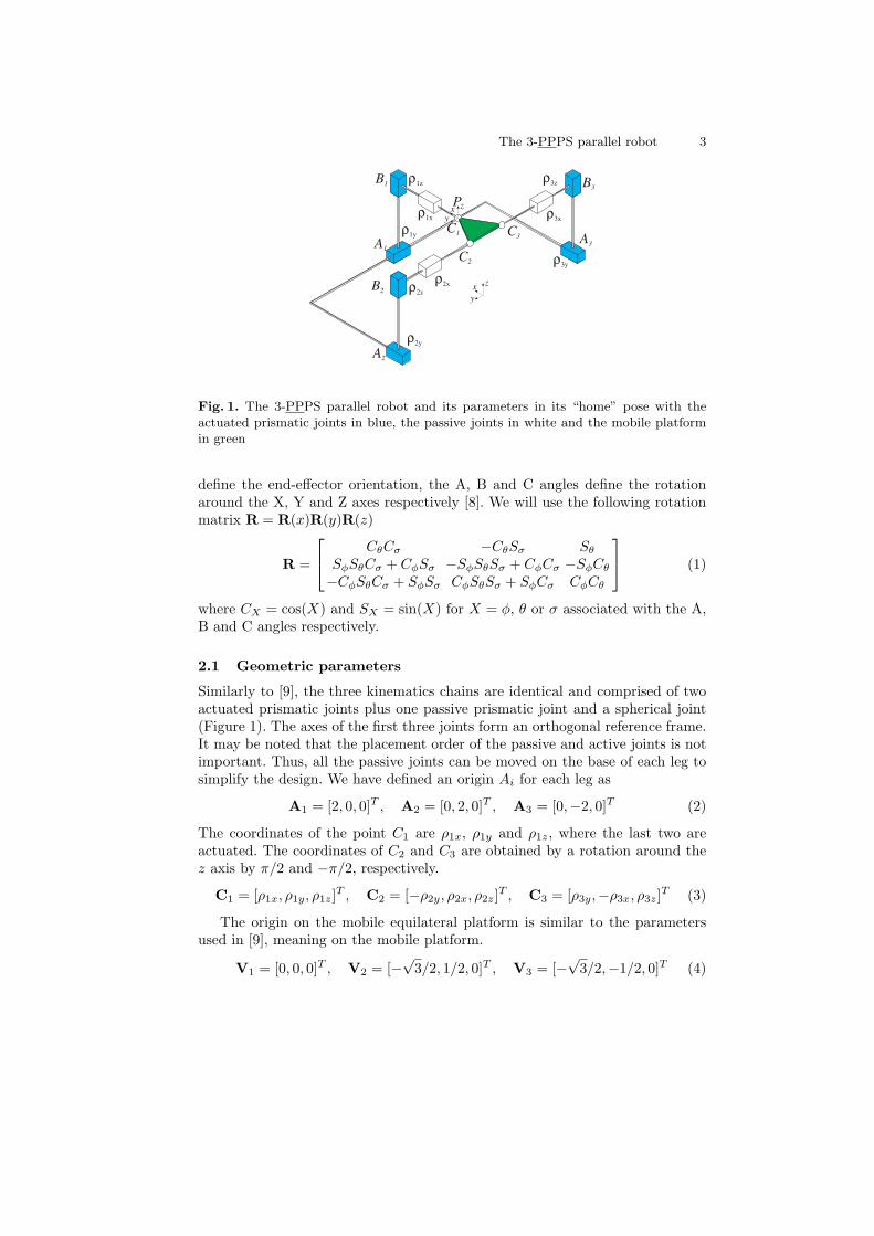
Fig. 1. The 3-PPPS parallel robot and its parameters in its “home” pose with theactuated prismatic joints in blue, the passive joints in white and the mobile platformin green
define the end-effector orientation, the A, B and C angles define the rotationaround the X, Y and Z axes respectively [8]. We will use the following rotationmatrix R = R(x)R(y)R(z)
R =
CθCσ −CθSσ Sθ
SφSθCσ + CφSσ −SφSθSσ + CφCσ −SφCθ
−CφSθCσ + SφSσ CφSθSσ + SφCσ CφCθ
(1)
where CX = cos(X) and SX = sin(X) for X = φ, θ or σ associated with the A,B and C angles respectively.
2.1 Geometric parameters
Similarly to [9], the three kinematics chains are identical and comprised of twoactuated prismatic joints plus one passive prismatic joint and a spherical joint(Figure 1). The axes of the first three joints form an orthogonal reference frame.It may be noted that the placement order of the passive and active joints is notimportant. Thus, all the passive joints can be moved on the base of each leg tosimplify the design. We have defined an origin Ai for each leg as
A1 = [2, 0, 0]T , A2 = [0, 2, 0]T , A3 = [0,−2, 0]T (2)
The coordinates of the point C1 are ρ1x, ρ1y and ρ1z, where the last two areactuated. The coordinates of C2 and C3 are obtained by a rotation around thez axis by π/2 and −π/2, respectively.
C1 = [ρ1x, ρ1y, ρ1z]T , C2 = [−ρ2y, ρ2x, ρ2z]
T , C3 = [ρ3y,−ρ3x, ρ3z]T (3)
The origin on the mobile equilateral platform is similar to the parametersused in [9], meaning on the mobile platform.
V1 = [0, 0, 0]T , V2 = [−√3/2, 1/2, 0]T , V3 = [−
√3/2,−1/2, 0]T (4)
4 Damien Chablat et al.
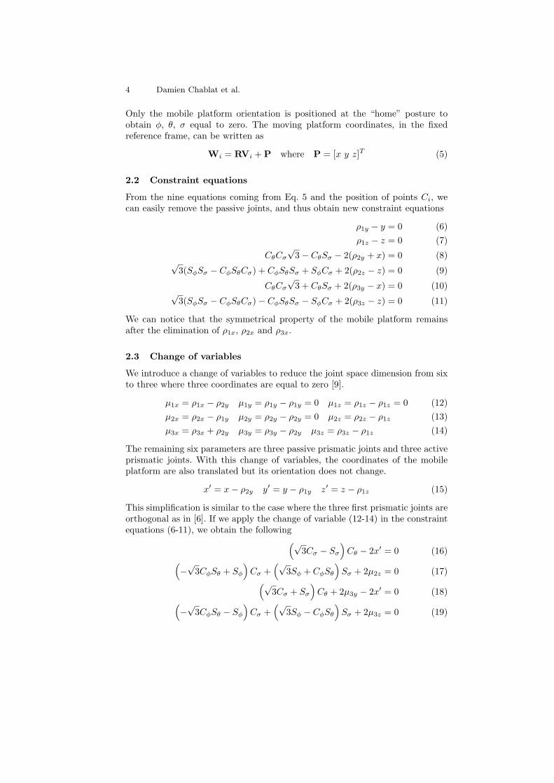
Only the mobile platform orientation is positioned at the “home” posture toobtain φ, θ, σ equal to zero. The moving platform coordinates, in the fixedreference frame, can be written as
Wi = RVi +P where P = [x y z]T (5)
2.2 Constraint equations
From the nine equations coming from Eq. 5 and the position of points Ci, wecan easily remove the passive joints, and thus obtain new constraint equations
ρ1y − y = 0 (6)
ρ1z − z = 0 (7)
CθCσ
√3− CθSσ − 2(ρ2y + x) = 0 (8)
√3(SφSσ − CφSθCσ) + CφSθSσ + SφCσ + 2(ρ2z − z) = 0 (9)
CθCσ
√3 + CθSσ + 2(ρ3y − x) = 0 (10)
√3(SφSσ − CφSθCσ)− CφSθSσ − SφCσ + 2(ρ3z − z) = 0 (11)
We can notice that the symmetrical property of the mobile platform remainsafter the elimination of ρ1x, ρ2x and ρ3x.
2.3 Change of variables
We introduce a change of variables to reduce the joint space dimension from sixto three where three coordinates are equal to zero [9].
µ1x = ρ1x − ρ2y µ1y = ρ1y − ρ1y = 0 µ1z = ρ1z − ρ1z = 0 (12)
µ2x = ρ2x − ρ1y µ2y = ρ2y − ρ2y = 0 µ2z = ρ2z − ρ1z (13)
µ3x = ρ3x + ρ2y µ3y = ρ3y − ρ2y µ3z = ρ3z − ρ1z (14)
The remaining six parameters are three passive prismatic joints and three activeprismatic joints. With this change of variables, the coordinates of the mobileplatform are also translated but its orientation does not change.
x′ = x− ρ2y y′ = y − ρ1y z′ = z − ρ1z (15)
This simplification is similar to the case where the three first prismatic joints areorthogonal as in [6]. If we apply the change of variable (12-14) in the constraintequations (6-11), we obtain the following
(√3Cσ − Sσ
)
Cθ − 2x′ = 0 (16)(
−√3CφSθ + Sφ
)
Cσ +(√
3Sφ + CφSθ
)
Sσ + 2µ2z = 0 (17)(√
3Cσ + Sσ
)
Cθ + 2µ3y − 2x′ = 0 (18)(
−√3CφSθ − Sφ
)
Cσ +(√
3Sφ − CφSθ
)
Sσ + 2µ3z = 0 (19)

The 3-PPPS parallel robot 5
3 Inverse and direct kinematics of the 3-PPPS parallel
robot
Finding the solutions of the direct geometric model of a parallel robot is oftena difficult problem, especially for robots with six degrees of freedom. If in [9]for the mechanism studied, a compact form was found, the use of Euler anglescould lead to more complex expressions. With the Siropa library, it is possible toobtain the kinematic models by using the Grobner based elimination method bychanging the constraint equation in an algebraic form. A classical approach canbe used to transform the trigonometric equations to algebraic ones as in [10].
3.1 Inverse kinematic model
Thanks to the choice of the origin on the mobile platform which is fixed at C1,it is straightforward to find the joint positions of the first kinematics chain :
ρ1y = y and ρ1z = z (20)
For the two other kinematics chain, the result keeps the symmetric property andbecomes
ρ2y =Cθ
(
Cσ
√3− Sσ
)
2− x (21)
ρ2z =
√3 (CφSθCσ − SφSσ)− CφSθSσ − SφCσ
2+ z (22)
ρ3y = −Cθ
(
Cσ
√3 + Sσ
)
2+ x (23)
ρ3z =
√3 (CφSθCσ − SφSσ) + CφSθSσ + SφCσ
2+ z (24)
The computational cost to solve the inverse kinematics handles six trigonometricfunctions (sine and cosine), the square of three, 14 multiplications/divisions and11 additions/subtractions if we used the code generation of Maple with theoptimization function to create intermediary variables.
3.2 Direct kinematic model
The computation of the position does not depend on the choice of parametersfor the orientation. For the position, we have the similar results than in [9].
x =µ2z
2µ3y − µ2zµ3yµ3z − µ3y/2
(µ2z − µ3z + 1) (µ2z − µ3z − 1)(25)
±√
(µ2z2 − µ2zµ3z + µ3z
2 − 3/4) (µ2z2 − 2µ2zµ3z + µ3y
2 + µ3z2 − 1)
(µ2z − µ3z + 1) (µ2z − µ3z − 1)
6 Damien Chablat et al.
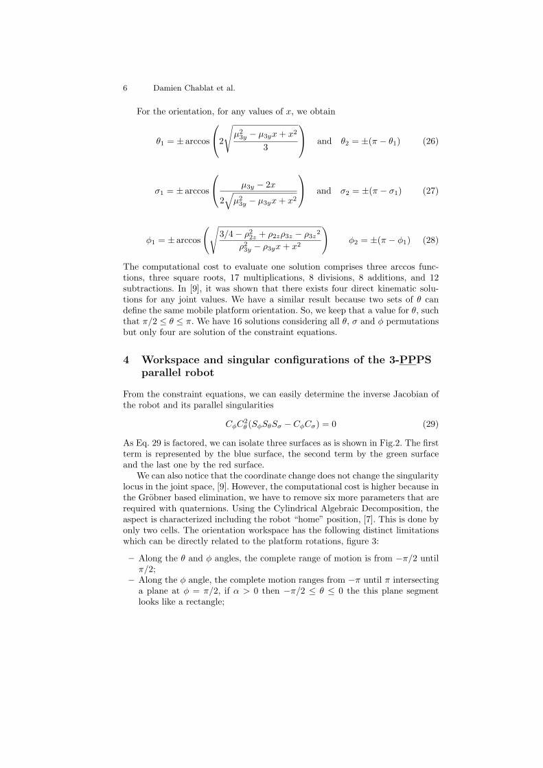
For the orientation, for any values of x, we obtain
θ1 = ± arccos
2
√
µ2
3y − µ3yx+ x2
3
and θ2 = ±(π − θ1) (26)
σ1 = ± arccos
µ3y − 2x
2√
µ2
3y − µ3yx+ x2
and σ2 = ±(π − σ1) (27)
φ1 = ± arccos
(√
3/4− ρ22z + ρ2zρ3z − ρ3z2
ρ23y − ρ3yx+ x2
)
φ2 = ±(π − φ1) (28)
The computational cost to evaluate one solution comprises three arccos func-tions, three square roots, 17 multiplications, 8 divisions, 8 additions, and 12subtractions. In [9], it was shown that there exists four direct kinematic solu-tions for any joint values. We have a similar result because two sets of θ candefine the same mobile platform orientation. So, we keep that a value for θ, suchthat π/2 ≤ θ ≤ π. We have 16 solutions considering all θ, σ and φ permutationsbut only four are solution of the constraint equations.
4 Workspace and singular configurations of the 3-PPPS
parallel robot
From the constraint equations, we can easily determine the inverse Jacobian ofthe robot and its parallel singularities
CφC2
θ (SφSθSσ − CφCσ) = 0 (29)
As Eq. 29 is factored, we can isolate three surfaces as is shown in Fig.2. The firstterm is represented by the blue surface, the second term by the green surfaceand the last one by the red surface.
We can also notice that the coordinate change does not change the singularitylocus in the joint space, [9]. However, the computational cost is higher because inthe Grobner based elimination, we have to remove six more parameters that arerequired with quaternions. Using the Cylindrical Algebraic Decomposition, theaspect is characterized including the robot “home” position, [7]. This is done byonly two cells. The orientation workspace has the following distinct limitationswhich can be directly related to the platform rotations, figure 3:
– Along the θ and φ angles, the complete range of motion is from −π/2 untilπ/2;
– Along the φ angle, the complete motion ranges from −π until π intersectinga plane at φ = π/2, if α > 0 then −π/2 ≤ θ ≤ 0 the this plane segmentlooks like a rectangle;

The 3-PPPS parallel robot 7
Fig. 2. The three singularity surface of the3-PPPS parallel robot
Fig. 3. The aspect of the 3-PPPS parallelrobot around the “home” pose
– On the other side, accordingly, intersecting a plane at φ = −π/2, if α < 0then 0 ≤ θ ≤ pi/2 meaning a symmetrical rectangle appears. These twosymmetrical rectangles will evolve towards the other side as φ is changedfrom π/2 to−π/2. In the middle, intersecting a plane at φ = 0, the workspaceis a square with sides at −π/2 and π/2.
Hence, the θ range divides itself differently if α is positive or negative withtraveling symmetrical rectangles. This results from the selected symmetries andaxis positions. These traveling or sliding rectangles actually produce two inter-esting saddle points on the workspace limit where α = 0 and θ = 0. Hence,the graph solution is geometrically confirming the displacement limitations thatcan be intuitively understood from manipulator observation. These workspacedistinct limits come from the passive prismatic joints.
5 Conclusions
In this article, we introduced kinematics modeling where the orientation rep-resentation of the 3-PPPS mobile platform implemented the Euler angles asit is often represented on many machine tools followed by a significant variablechange. We can see that the equations of the direct and inverse kinematics modelremain very compact. An estimate of the calculation cost is presented. Since theequations are quadratic, it is possible to obtain an analytical expression whichis not possible for most parallel robots with 6 degrees of freedom. A representa-tion of the aspect encompassing the “home” position is given. Conversely to the5-axis Orthoglide [11] or 4-axis Kanuk [12], the 3-PPPS parallel robot is using 6identical linear or prismatic actuators as a Gough-Stewart platform. Inside eachkinematic chain, the passive and active joint order can be changed to obtain, forexample, the passive joint fixed into the base without altering the singularity

8 Damien Chablat et al.
and aspect results. Future works will be done to characterize the stiffness modelas well as to know the influence of the joint limits in the spherical joints.
References
1. Paul, Richard P, Robot manipulators: mathematics, programming, and control: thecomputer control of robot manipulators, Richar Paul, 1981.
2. Bruno, Siciliano and Oussama, Khatib. 2007. Springer Handbook of Robotics.Springer-Verlag New York, Inc., Secaucus, NJ, USA.
3. Merlet, J. P., “Parallel robots”, Springer Science & Business Media, 2006.4. Kong, X. and Gosselin, C.M., 2002, “Type synthesis of linear translational par-
allel manipulators,” in Lenarcic, J. and Thomas, F. (editors), Advances in Robot
Kinematic, Kluwer Academic Publishers, June, pp. 453–462.5. Chen, C., Gayral, T., Caro, S., Chablat, D., Moroz, G., “A Six-Dof Epicyclic-Parallel
Manipulator,” Journal of Mechanisms and Robotics, American Society of Mechan-ical Engineers, Vol. 4 (4), pp.041011-1-8, 2012.
6. Caro, S., Wenger, P. and Chablat, D., “Non-Singular Assembly Mode ChangingTrajectories of a 6-DOF Parallel Robot,” ASME Design Engineering Technical Con-ferences & Computers and Information in Engineering Conference IDETC/CIE,Chicago, August 12-15, USA, 2012.
7. Manubens M., Moroz G., Chablat D., Wenger P., Rouillier F., Cusp Points in theParameter Space of Degenerate 3-RPR Planar Parallel Manipulators, ASME Jour-nal of Mechanisms and Robotics, Vol. 10(1), 2012.
8. Lamikiz A. , Lopez de Lacalle L. N. , Ocerin O., Dıez D., and Maidagan E., “TheDenavit and Hartenberg approach applied to evaluate the consequences in the tooltip position of geometrical errors in five-axis milling centres,” Int J Adv ManufTechnol (2008) 37:122139.
9. Chablat D., Baron L., Jha R., “Kinematics and Workspace Analysis of a 3PPPSParallel Robot with U-Shaped Base,” International Design Engineering TechnicalConferences & Computers and Information in Engineering Conference, 2017.
10. Moroz G., Rouiller F., Chablat D., Wenger P., On the determination of cusp pointsof 3-RPR parallel manipulators, Mechanism and Machine Theory, Vol. 45(11), pp.1555-1567, 2010.
11. Caro S., Chablat D., Lemoine P., Wenger P., Kinematic Analysis and TrajectoryPlanning of the Orthoglide 5-Axis, Proceedings of the ASME 2015 , InternationalDesign Engineering Technical Conferences & Computers and Information in Engi-neering Conference, Aug 2015, Boston, United States, 2015.
12. Rolland L. The Manta and the Kanuk: Novel 4-DOF Parallel Mechanisms forIndustrial Handling. In proceedings of the ASME, Dynamic Systems and ControlDivision - 1999, vol 67, pp 831 - 844, Conference IMECE’99, Nashville, novembre14-19, 1999.