9th international radar symposium india - 2013 (irsi - 13 ... · performance analysis of various...
TRANSCRIPT

Performance Analysis of Various Constant
False Alarm Receivers in non
backgroundSibilkumar TB
1,, Badarinath R
Electronics & Radar Development EstablishmentDefence Research & C V Raman Nagar, Bangalore
Abstract:- Constant False Alarm R
in non-homogeneous environment
essential requirement of modern
radars. This paper compares various CFAR
techniques and proposes a new approach for
selecting the best CFAR method for
based radar which has multiple receive beams
in both elevation and azimuth within a single
burst. The CFAR selection scheme provides an
improved performance as compared to
applying uniform algorithms across the entire
RADAR’s volume coverage. False alarm
control performance of different
schemes is exhaustively studied across various
papers. This paper extends towards how thes
CFAR techniques can be effectively util
Multi-Mission radar, which is having multiple
beams in a single dwell.
I. INTRODUCTION
In order to achieve the best possible update
rate, the latest active phased array radars are
configured with wide transmit beam and
multiple receive beams, both in elevation a
azimuth angle. The detection of signal becomes
complex and time consuming in case of
having multiple beams in both elevation
azimuth, because its returns are non
(added with noise-plus-clutter) in lower
elevation angle and near range. But
regions are clear compared to low elevation,
the absence of Electronic Counter
(ECMs) and atmospheric clutters. In this type
Performance Analysis of Various Constant
False Alarm Receivers in non-homogeneous
background for Multi-Mission RadarBadarinath R
2, Mohana kumari M
3, Dr. A Vengadarajan
Electronics & Radar Development Establishment Defence Research & Development Organisation C V Raman Nagar, Bangalore – 560 093, India.
Email: [email protected]
Rate (CFAR)
homogeneous environment is an
modern military
. This paper compares various CFAR
techniques and proposes a new approach for
method for ground
radar which has multiple receive beams
elevation and azimuth within a single
on scheme provides an
improved performance as compared to
across the entire
. False alarm
control performance of different CFAR
is exhaustively studied across various
towards how these
CFAR techniques can be effectively utilized in
having multiple
best possible update
active phased array radars are
wide transmit beam and
in elevation and
. The detection of signal becomes
in case of a radar
elevation and
returns are non-stationary
clutter) in lower
ut the other
compared to low elevation, in
ounter Measures
. In this type
of scenario if the radar depends only on
conventional type of CFAR
complete obliteration of the
can lead to overloading of the t
makes Yes/No decisions for a valid echo
reduce this problem, radar detectio
can be chosen based on the scenario of
operation as well as processing
elevations.
The radar environment is sectored into
low-angle/altitude and high altitude regions.
Clutter is more in low angle and low altitude
regions. In high altitude, the possibility of
weather clutter is unavoidable. Different CFAR
schemes are analyzed for non
conditions like clutter edge and mu
conditions .Best usable scheme
for different sectors / beams.
Figure -1: Radar Environment
II. Typical CFAR detector
CFAR detection is performed at eac
resolution cell in the range-
a sliding window along each row of the matrix
Performance Analysis of Various Constant
homogeneous
adar Dr. A Vengadarajan
4
of scenario if the radar depends only on
CFARs, that can lead to
of the radar display or
ing of the tracker which
ons for a valid echo. To
reduce this problem, radar detection processing
chosen based on the scenario of
as processing range and
The radar environment is sectored into two
altitude and high altitude regions.
Clutter is more in low angle and low altitude
gh altitude, the possibility of
weather clutter is unavoidable. Different CFAR
schemes are analyzed for non-homogeneous
dge and multi-target
est usable schemes are proposed
beams.
Radar Environment
Typical CFAR detector
CFAR detection is performed at each
-Doppler map using
a sliding window along each row of the matrix
9th International Radar Symposium India - 2013 (IRSI - 13)
NIMHANS Convention Centre, Bangalore INDIA 1 10-14 December 2013
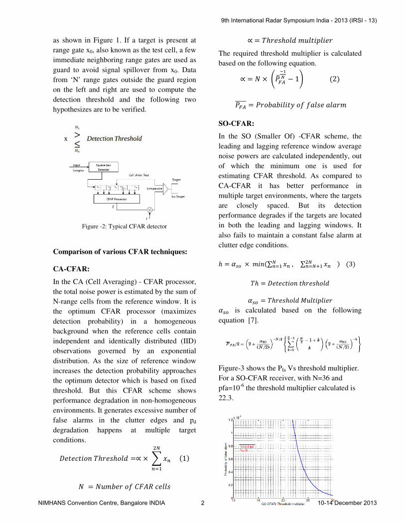
as shown in Figure 1. If a target is present at
range gate x0, also known as the test cell, a few
immediate neighboring range gates are used as
guard to avoid signal spillover from x0. Data
from ‘N’ range gates outside the guard region
on the left and right are used to compute the
detection threshold and the following two
hypothesizes are to be verified.
Figure -2: Typical CFAR detector
Comparison of various CFAR techniques:
CA-CFAR:
In the CA (Cell Averaging) - CFAR processor,
the total noise power is estimated by the sum of
N-range cells from the reference window. It is
the optimum CFAR processor (maximizes
detection probability) in a homogeneous
background when the reference cells contain
independent and identically distributed (IID)
observations governed by an exponential
distribution. As the size of reference window
increases the detection probability approaches
the optimum detector which is based on fixed
threshold. But this CFAR scheme shows
performance degradation in non-homogeneous
environments. It generates excessive number of
false alarms in the clutter edges and pd
degradation happens at multiple target
conditions.
��������� ℎ���ℎ� � =∝ × � �� �1���
���
� = ������ � !"#$ �� �
∝ = ℎ���ℎ� � �� ��% ���
The required threshold multiplier is calculated
based on the following equation.
∝ = � × &'()*+,- − 1/ �2�
')*((((( = '���1�� ��2 � 1 �� 1 1��
SO-CFAR:
In the SO (Smaller Of) -CFAR scheme, the
leading and lagging reference window average
noise powers are calculated independently, out
of which the minimum one is used for
estimating CFAR threshold. As compared to
CA-CFAR it has better performance in
multiple target environments, where the targets
are closely spaced. But its detection
performance degrades if the targets are located
in both the leading and lagging windows. It
also fails to maintain a constant false alarm at
clutter edge conditions.
ℎ = 3�� × ����∑ �� , ���� ∑ �� �����6� � �3� ℎ = ��������� �ℎ���ℎ� �
389 = ℎ���ℎ� � :� ��% ��� 389 is calculated based on the following
equation [7].
Figure-3 shows the Pfa Vs threshold multiplier.
For a SO-CFAR receiver, with N=36 and
pfa=10-6
the threshold multiplier calculated is
22.3.
9th International Radar Symposium India - 2013 (IRSI - 13)
NIMHANS Convention Centre, Bangalore INDIA 2 10-14 December 2013

Figure -3: 389 ;� ' 1
GO-CFAR:
The GO (Greater Of) -CFAR procedure is
specifically aimed at reducing the number of
false alarms at clutter edges. The total noise
power is calculated from the greater of two
separate noise averages are calculated from the
leading and lagging window. Though GO-
CFAR performs well in clutter edge conditions,
it is incapable to resolve closely spaced targets.
It also introduces additional loss of detection
compared with the CA-CFAR processor in the
homogeneous environment. However the loss
is found to be less and is generally quite
acceptable.
ℎ = 3<= × �1� >� �� , �
���� �� ��
���6�? �4�
3AB = ℎ���ℎ� � :� ��% ���
The threshold multiplier is calculated based on
the following equation [7].
Figure-4 shows the Pfa Vs threshold
multiplier. For a GO-CFAR receiver, with
N=36 and pfa=10-6
the threshold multiplier
calculated is 15.5
Figure -4: 3AB ;� ' 1
OS CFAR
For an Order-Statistics CFAR receiver,
threshold is obtained from one of the ordered
samples of the reference window. The range
samples are first ordered according to their
magnitudes, and the noise sample is taken to be
the kth
largest sample, the required threshold
multiplier 3BC is calculated based on the
following equation [7].
Figure-5 shows the pfa Vs threshold
multiplier. For a OS-CFAR receiver, with
N=36 and pfa=10-6
the threshold multiplier
calculated is 13.86.
Figure -5: 389 ;� ' 1
Variability Index CFAR (VI-CFAR)
VI-CFAR is a composite of CA-CFAR, SO-
CFAR and GO-CFAR The background
estimation algorithm dynamically selects the
appropriate of these three by utilizing the
variability index (VI) and Mean ratio (MR)
statistics [8]. VI-CFAR has satisfactory
performance in homogeneous background. For
homogeneous environment its performance
approaches that of CA-CFAR, offering low
loss CFAR operation. It provides robustness
against non-homogeneities.
III. Simulation Results
Figure 6 shows the SNR vs probability
of detection plot for CA, SO, GO, OS and VI
CFAR receivers in homogeneous environment.
It shows almost similar performance in
9th International Radar Symposium India - 2013 (IRSI - 13)
NIMHANS Convention Centre, Bangalore INDIA 3 10-14 December 2013
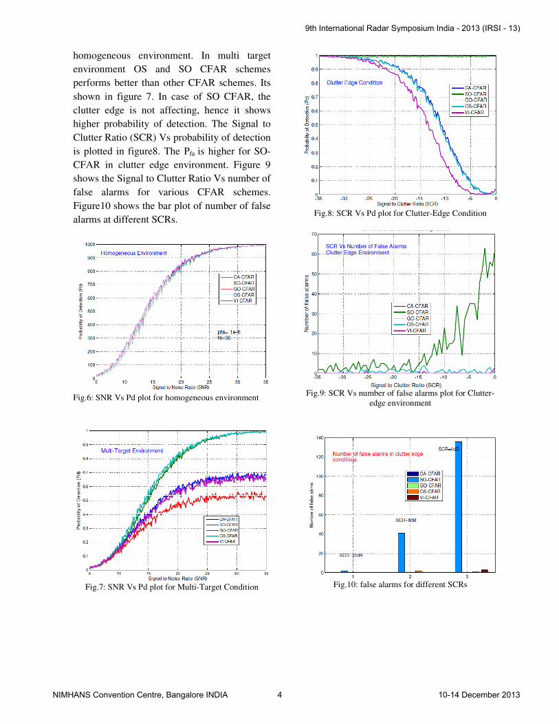
homogeneous environment. In multi target
environment OS and SO CFAR schemes
performs better than other CFAR schemes. Its
shown in figure 7. In case of SO CFAR, the
clutter edge is not affecting, hence it shows
higher probability of detection. The Signal to
Clutter Ratio (SCR) Vs probability of detection
is plotted in figure8. The Pfa is higher for SO-
CFAR in clutter edge environment. Figure 9
shows the Signal to Clutter Ratio Vs number of
false alarms for various CFAR schemes.
Figure10 shows the bar plot of number of false
alarms at different SCRs.
Fig.6: SNR Vs Pd plot for homogeneous environment
Fig.7: SNR Vs Pd plot for Multi-Target Condition
Fig.8: SCR Vs Pd plot for Clutter-Edge Condition
Fig.9: SCR Vs number of false alarms plot for Clutter-
edge environment
Fig.10: false alarms for different SCRs
9th International Radar Symposium India - 2013 (IRSI - 13)
NIMHANS Convention Centre, Bangalore INDIA 4 10-14 December 2013
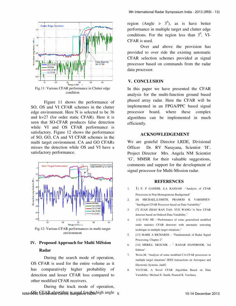
Fig.11: Various CFAR performance in Clutter edge
condition
Figure 11 shows the performance of
SO, OS and VI CFAR schemes in the clutter
edge environment. Here N is selected to be 36
and k=27 (for order static CFAR). Here it is
seen that SO-CFAR produces false detection
while VI and OS CFAR performance is
satisfactory. Figure 12 shows the performance
of SO, GO, CA and VI CFAR schemes in the
multi target environment. CA and GO CFARs
misses the detection while OS and VI have a
satisfactory performance.
Fig.12: Various CFAR performances in multi-target
environment
IV. Proposed Approach for Multi MiSsion
Radar
During the search mode of operation,
OS CFAR is used for the entire volume as it
has comparatively higher probability of
detection and lesser CFAR loss compared to
other modified CFAR receivers.
During the track mode of operation,
OS- CFAR algorithm is used for the high angle
region (Angle > 30), as is have better
performance in multiple target and clutter edge
conditions. For the region less than 30, VI-
CFAR is used.
Over and above the provision has
provided to over ride the existing automatic
CFAR selection schemes provided at signal
processor based on commands from the radar
data processor.
V. CONCLUSION
In this paper we have presented the CFAR
analysis for the multi-function ground based
phased array radar. Here the CFAR will be
implemented in an FPGA/PPC based signal
processor board, where these complex
algorithms can be implemented in much
efficiently.
ACKNOWLEDGEMENT
We are grateful Director LRDE, Divisional
Officer Dr. RV Narayana, Scientist ‘H’,
Project Director Mrs. Angela NM Scientist
‘G’, MMSR for their valuable suggestions,
comments and support for the development of
signal processor for Multi-Mission radar.
REFERENCES
1. 1] P. P GANDHI, S.A KASSAM –“Analysis of CFAR
Processors in Non Homogeneous Background”
2. [6] MICHAEL.E.SMITH, PRAMOD K VARSHNEY-
“Intelligent CFAR Processor based on Data Variability”
3. [7] JUAN ZHAO RAN TAO, YUE WANG-“A New CFAR
detector based on Ordered Data Variability.”
4. [12] YOU HE –“Performance of some generalized modified
order statistics CFAR detectors with automatic sensoring
technique in multiple target situations.”
5. [13] MARK A RICHARDS – “Fundamentals of Radar Signal
Processing, Chapter-2”
6. [14] MERILL SKOLNIK - " RADAR HANDBOOK, 3rd
Edition"
7. Weiss,M, “Analysis of some modified CA-CFAR processors in
multiple target situations”.IEEE transactions on Aerospace and
Electronic Systems. Jan82
8. VI-CFAR: A Novel CFAR Algorithm Based on Data
Variability: Michael E. Smith, Pramod K. Varshney
9th International Radar Symposium India - 2013 (IRSI - 13)
NIMHANS Convention Centre, Bangalore INDIA 5 10-14 December 2013

BIO DATA OF AUTHORS
Mr. Badarinath. R has obtained his B.E in
Electronis and communication from
IE(India), Kolkatta. He is presently working
as scientist ‘C’ in Electronics and Radar
development establishment in area of radar
signal processing. His area of interest
include radar signal processing.
Mrs Mohana Kumari P received B-Tech in
ECE from JNTU college of Engineering
Ananthapur and M-Tech in Digital
Communication from RV College of
Engineering. She is working as a scientist in
the field of Radar Signal Processing at
LRDE, DRDO.
Dr. Vengadarajan: Graduated from Madurai
Kamaraj University in 1985. He completed
M.Tech in 1992 and Ph.D in 2003 from IIT
Kharagpur. Joined CABS, DRDO in 1986
and presently working as a scientist ‘F’ on
Array and Radar signal processing at LRDE,
DRDO. His other area of interest are
Synthetic aperture Radar and space time
adaptive processing.
Mr. Sibilkumar TB received B Tech in
E&CE from College of Egg,Trivandrum,
Kerala, India in 2003. He had worked as a
lecturer in Cochin University College of
Engg, Alappuzha and LBS Engg. College,
Kasaragod. Presently he is working as a
scientist in LRDE, DRDO, Bangalore. His
main research interests are Radar Digital
Receivers and Radar Signal Processing.
9th International Radar Symposium India - 2013 (IRSI - 13)
NIMHANS Convention Centre, Bangalore INDIA 6 10-14 December 2013