9k series service manual - locksmith security … 9k series service manual.pdfcontents iv 9k series...
TRANSCRIPT

CREDITS/COPYRIGHT
©2000-2002 Best Lock Corporation dba Best Access Systems. All rights reserved. Printed in the United States of America.
Information in this document is subject to change without notice and does not represent a commitment on the part of Best Access Systems. The software described in this document are furnished under a license agreement or nondisclosure agreement.
This publication is intended to be an accurate description and set of instructions pertaining to its subject matter. However, as with any publication of this complexity, errors or omissions are possible. Please call your BEST distributor or Best Access Systems at (317) 849-2250 if you see any errors or have any questions. No part of this manual and/or databases may be reproduced or transmitted in any form or by any means, electronic or mechanical, including photocopying, recording, or information storage and retrieval systems, for any purpose, without the express written permission of Best Access Systems.
This document is distributed as is, without warranty of any kind, either express or implied, respecting the contents of this book, including but not limited to implied warranties for the publication’s quality, performance, merchantability, or fitness for any particular purpose. Neither Best Access Systems, nor its dealers or distributors shall be liable to the user or any other person or entity with respect to any liability, loss, or damage caused or alleged to be caused directly or indirectly by this publication.
The Life Safety Code is a registered trademark of the National Fire Protection Association.
Written and designed by Best Access Systems and Avalon Group, Inc., Indianapolis, Indiana.
T56082 Rev B 1798144 ER-7991-6 May 2002
9K Series Service
CONTENTS
FIGURES VII
GETTING STARTED 1–1
Introduction 1–1
Certifications and standards 1–1
Documentation package 1–2
Technical support 1–2
Support services 1–2Telephone technical support 1–2Training seminars 1–3
FUNCTIONS AND PARTS LISTS 2–1
Function descriptions 2–2
Single-keyed functions 2–2Double-keyed functions 2–4Non-keyed functions 2–6Special functions 2–7Functions by ANSI designation 2–9
Standard functions 2–10
AB function chassis—entrance lock (ANSI F109) 2–10C function chassis—corridor lock (ANSI F88) 2–11D function chassis—storeroom lock (ANSI F86) 2–12E function chassis—service station lock (ANSI F92) 2–13G function chassis—storeroom lock (ANSI F91) 2–14H function chassis—hotel guest room lock with
indicator (ANSI F93) 2–15HJ function chassis—hotel guest room lock without indicator 2–15L function chassis—privacy lock (ANSI F76) 2–16
Manual iii
Contents
iv
N function chassis—passage lock (ANSI F75) 2–17NX function chassis—exit lock (ANSI F89) 2–18P function chassis—patio lock (ANSI F77) 2–19R function chassis—classroom lock (ANSI F84) 2–20S function chassis—communicating lock (ANSI F80) 2–21T function chassis—dormitory lock (ANSI F90) 2–22W function chassis—utility or institutional lock (ANSI F87) 2–23Y function chassis—exit lock 2–24
Non-standard functions 2–25
A function chassis—entrance lock (ANSI F81) 2–25B function chassis—office lock (ANSI F82) 2–26DR function chassis—special lock 2–27DZ function chassis—closet or storeroom lock 2–28EA function chassis—entrance or office lock 2–29IN function chassis—intruder lock 2–30LL function chassis—hospital privacy lock 2–31M function chassis—communicating lock (ANSI F78) 2–32Q function chassis—exit lock (ANSI F83) 2–33RD function chassis—special lock 2–34RZ function chassis—closet or storeroom lock 2–35XD function chassis—special lock 2–36XR function chassis—special lock 2–37YD function chassis—exit lock 2–38YR function chassis—special lock 2–39Z function chassis—closet lock 2–40
Function conversion 2–41
Trim parts 2–44
Standard strikes and strike boxes 2–44Non-standard strikes 2–44Roses, rose liners, and rose spacers 2–45Standard levers and components 2–47Non-IC levers and components 2–49Dummy trim 2–51Latches 2–52Installation tools 2–53
SERVICE AND MAINTENANCE 3–1
Maintenance tools 3–2
Maintenance tools parts list 3–2
Replacing Parts 3–3
Replacing the lever 3–3Replacing the inside rose and rose liner 3–4Replacing the outside rose and liner assembly 3–5Replacing the button assembly 3–7Replacing the lever keeper spring 3–9Replacing the lever return spring 3–10
9K Series Service Manual
Contents
9K Series Service
Replacing the key release cam assembly 3–14Replacing the spring drive plate 3–15Replacing the sleeve assembly 3–16
Lubricating the cores 3–18
Aligning the chassis and trim 3–19
Cam positioning instructions 3–20
Positioning the cam for C function locks 3–20Positioning the cam for G and IN function locks 3–21
Emergency key instructions for H and HJ function locks 3–22
Troubleshooting 3–23
INSTALLATION INSTRUCTIONS A–1
INDEX B–1
Manual v
Contents
vi
9K Series Service Manual
9K Series Service
FIGURES
FUNCTIONS AND PARTS LISTS
Understanding function drawings 2–2
AB function exploded diagram 2–10
C function exploded diagram 2–11
D function exploded diagram 2–12
E function exploded diagram 2–13
G function exploded diagram 2–14
H/HJ function exploded diagram 2–15
L function exploded diagram 2–16
N function exploded diagram 2–17
NX function exploded diagram 2–18
P function exploded diagram 2–19
R function exploded diagram 2–20
S function exploded diagram 2–21
T function exploded diagram 2–22
W function exploded diagram 2–23
Y function exploded diagram 2–24
A function exploded diagram 2–25
B function exploded diagram 2–26
DR function exploded diagram 2–27
DZ function exploded diagram 2–28
EA function exploded diagram 2–29
IN function exploded diagram 2–30
LL function exploded diagram 2–31
M function exploded diagram 2–32
Manual vii
Figures
viii
Q function exploded diagram 2–33
RD function exploded diagram 2–34
RZ function exploded diagram 2–35
XD function exploded diagram 2–36
XR function exploded diagram 2–37
YD function exploded diagram 2–38
YR function exploded diagram 2–39
Z function exploded diagram 2–40
Standard strikes and strike boxes 2–44
Understanding strike lip measurement 2–44
Roses, rose liners, and rose spacers 2–45
Standard levers 2–47
Standard lever components 2–48
Non-IC levers 2–49
Non-IC lever components 2–50
Dummy trim parts 2–51
Latches 2–52
Installation tools 2–53
Boring jig kit 2–54
SERVICE AND MAINTENANCE
Maintenance tools 3–2
Removing the keyed lever 3–3
Removing the plain lever or button lever 3–3
Replacing the lever (keyed lever shown) 3–4
Removing the inside rose with the spanner wrench 3–4
Removing the two through-bolts 3–5
Replacing the inside rose and rose liner 3–5
Removing the outside rose and liner assembly 3–6
Replacing the outside rose and liner assembly 3–6
Removing the button assembly 3–7
Inserting the button assembly into the sleeve 3–8
Bending the button assembly tab 3–8
Removing the lever keeper spring 3–9
Positioning the lever keeper spring 3–9
Lever keeper spring in position 3–10
Separating the hub and sleeve assembly from the chassis 3–11
Removing the thrust plate 3–11
Removing the lever return spring 3–11
9K Series Service Manual
Figures
9K Series Service
Positioning the lever return spring 3–12
Inserting the lever return spring 3–12
Installing the thrust plate 3–13
Positioning the retractor assembly 3–13
Installing the retractor assembly 3–14
Removing the key release cam assembly 3–14
Installing the key release cam assembly 3–15
Removing the spring drive plate 3–15
Positioning the sleeve 3–16
Installing the spring drive plate 3–16
Removing the sleeve assembly from the hub 3–17
Replacing the sleeve assembly 3–17
Positioning the sleeve 3–18
Engaging the retractor in the latch 3–19
Correct position of the C function inside locking cam 3–20
Correct position of the G and IN function locking cam 3–21
Intermediate position of the G and IN function locking cam 3–21
Inserting the emergency key 3–22
Manual ix
Figures
x
9K Series Service Manual
1
9K Series Service
GETTING STARTED
INTRODUCTIONThe 9K Series Service Manual contains essential information to help you maintain your 9K Series Lock.
CERTIFICATIONS AND STANDARDS■ The locks comply with ANSI A156.2, Series 4000
Grade 1 standards.
■ The locks are listed by Underwriter’s Laboratories for use on 3 Hr., A label single swinging doors (4´ x 10´), or pairs of doors 8´ wide and 10´ high.
■ The chassis conforms to ANSI A115.2.
■ The 8KS3 strike fits the standard door frame cutout as specified in ANSI A115.2.
■ The #14 and #15 lever handles conform to California Administrative Code Title 19 and Title 24.
■ The #14, #15, and #16 lever handles conform to the Illinois Accessibility Standard.
Manual 1–1
Getting Started
DOCUMENTATION PACKAGE The following documentation is available to help you with the installation, start-up, and maintenance of your 9K Series Lock.
The installation and assembly instructions also can be ordered separately:
The templates required for lock installations also can be ordered separately:
TECHNICAL SUPPORT
Supportservices
When you have a question about the 9K Series Lock, your first resource for help is the 9K Series Service Manual. If you cannot find a satisfactory answer, contact your local BEST Representative.
Telephonetechnical
support
A factory-trained Certified Product Specialist (CPS) is available in your area whenever you need help. Before you call, however, please make sure you are where the 9K Series Lock is, and that you are prepared to give the following information:
■ what happened and what you were doing when the question arose
■ what you have done so far to answer the question.
Document Title Doc. No.Installation Instructions for 9K Series Locks T56075
Single and Double Dummy Trim Assembly Instruc-tions for 9K1DT/2DT
T56076
Document Title Doc. No.K08 Template for Door and Frame Preparation for 63, 73, 83, 93K Locks
T56052
K09 Template for Door and Frame Preparation for 63, 73, 83, 93K Locks
T56053
K10 Template for Door and Frame Preparation for 64, 84, 94K Locks
T56054
K11 Template for Door and Frame Preparation for 64, 84, 94K
T56055
K12 Template for Door Frame Preparationfor 65, 85, 95K
T56056
K13 Template for Door Frame Preparationfor 65, 85, 95K
T56057
K18 Template for 8K/9K Dummy Trim T56059
K21 Template for Strike Specification for Cylindrical Locks
T56060
1–2 9K Series Service Manual
Getting Started
Best Access Systems Representatives provide telephone technical support for all 9K Series products. You may locate the representative nearest you by calling (317) 849-2250 Monday through Friday, between 7:00 a.m. and 4:00 p.m. eastern standard time; or visit the web page, www.BestAccess.com.
Trainingseminars
BEST holds training sessions for its customers. The seminars are specifically designed for BEST end-users who have a registered BEST masterkeyed system and registered BEST security equipment. If you are interested, you may contact your local BEST representative for details.
9K Series Service Manual 1–3
Getting Started
1–4 9K Series Service Manual
2
9K Series Service
FUNCTIONS AND PARTS LISTS
The following pages contain function descriptions for all 9K Series Locks. This chapter also includes exploded diagrams that show all field serviceable mechanical parts, diagrams of trim and other miscellaneous parts, and function conversion information.
For information about the DEU and DEL functions, see the W Series Service Manual.
Manual 2–1
Functions and Parts Lists
FUNCTION DESCRIPTIONSThis section includes function descriptions grouped by the following function types:
■ single-keyed (page 2–2)
■ double-keyed (page 2–4)
■ non-keyed (page 2–6)
■ special (page 2–7)
■ ANSI designation (page 2–9).
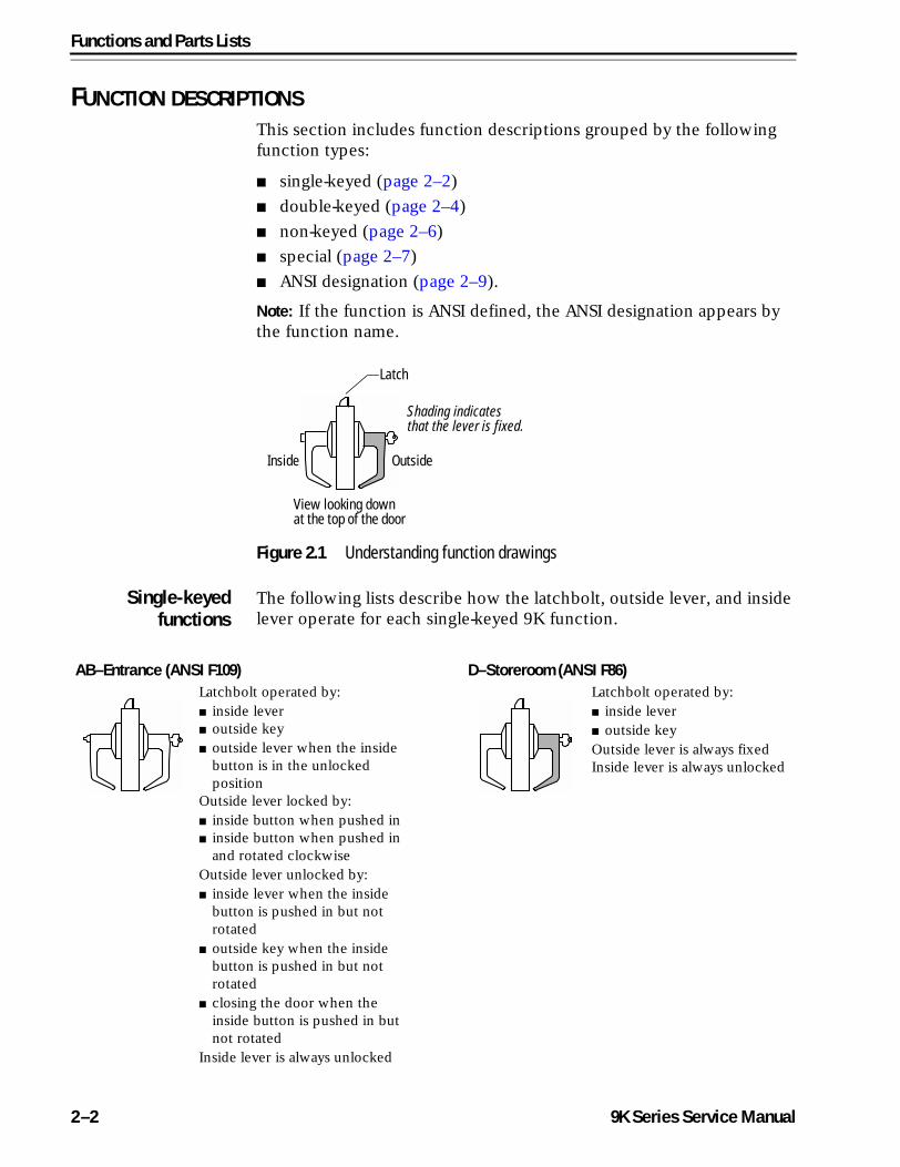
Note: If the function is ANSI defined, the ANSI designation appears by the function name.
Single-keyedfunctions
The following lists describe how the latchbolt, outside lever, and inside lever operate for each single-keyed 9K function.
Figure 2.1 Understanding function drawings
OutsideInside
Latch
Shading indicates that the lever is fixed.
View looking down at the top of the door
AB–Entrance (ANSI F109) D–Storeroom (ANSI F86)Latchbolt operated by:■ inside lever■ outside key■ outside lever when the inside
button is in the unlocked position
Outside lever locked by:■ inside button when pushed in■ inside button when pushed in
and rotated clockwiseOutside lever unlocked by:■ inside lever when the inside
button is pushed in but not rotated
■ outside key when the inside button is pushed in but not rotated
■ closing the door when the inside button is pushed in but not rotated
Inside lever is always unlocked
Latchbolt operated by:■ inside lever■ outside keyOutside lever is always fixedInside lever is always unlocked
2–2 9K Series Service Manual
Functions and Parts Lists
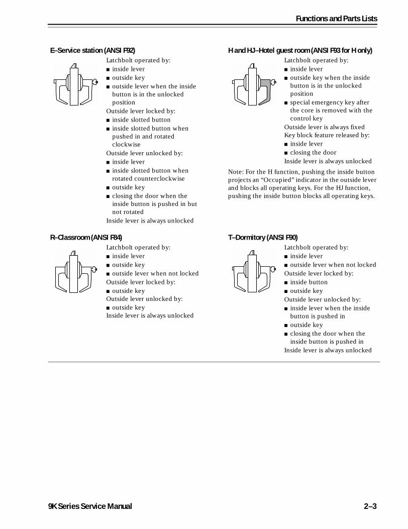
E–Service station (ANSI F92) H and HJ–Hotel guest room (ANSI F93 for H only)Latchbolt operated by:■ inside lever■ outside key■ outside lever when the inside
button is in the unlocked position
Outside lever locked by:■ inside slotted button■ inside slotted button when
pushed in and rotated clockwise
Outside lever unlocked by:■ inside lever■ inside slotted button when
rotated counterclockwise■ outside key■ closing the door when the
inside button is pushed in but not rotated
Inside lever is always unlocked
Latchbolt operated by:■ inside lever■ outside key when the inside
button is in the unlocked position
■ special emergency key after the core is removed with the control key
Outside lever is always fixedKey block feature released by:■ inside lever■ closing the doorInside lever is always unlocked
Note: For the H function, pushing the inside button projects an “Occupied” indicator in the outside lever and blocks all operating keys. For the HJ function, pushing the inside button blocks all operating keys.
R–Classroom (ANSI F84) T–Dormitory (ANSI F90)Latchbolt operated by:■ inside lever■ outside key■ outside lever when not lockedOutside lever locked by:■ outside keyOutside lever unlocked by:■ outside keyInside lever is always unlocked
Latchbolt operated by:■ inside lever■ outside lever when not locked Outside lever locked by:■ inside button■ outside keyOutside lever unlocked by:■ inside lever when the inside
button is pushed in■ outside key■ closing the door when the
inside button is pushed inInside lever is always unlocked
9K Series Service Manual 2–3
Functions and Parts Lists
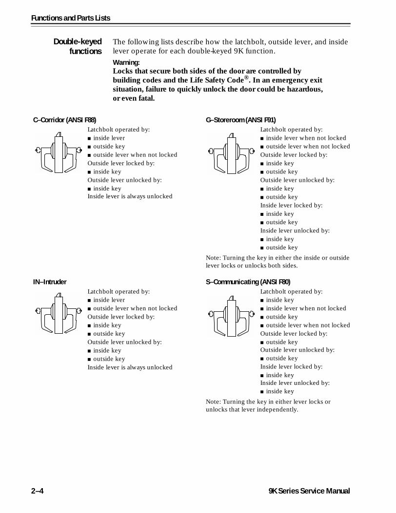
Double-keyedfunctions
The following lists describe how the latchbolt, outside lever, and inside lever operate for each double-keyed 9K function.
Warning: Locks that secure both sides of the door are controlled by building codes and the Life Safety Code®. In an emergency exit situation, failure to quickly unlock the door could be hazardous, or even fatal.
C–Corridor (ANSI F88) G–Storeroom (ANSI F91)Latchbolt operated by:■ inside lever■ outside key■ outside lever when not lockedOutside lever locked by:■ inside keyOutside lever unlocked by:■ inside keyInside lever is always unlocked
Latchbolt operated by:■ inside lever when not locked■ outside lever when not lockedOutside lever locked by:■ inside key■ outside keyOutside lever unlocked by:■ inside key■ outside keyInside lever locked by:■ inside key■ outside keyInside lever unlocked by:■ inside key■ outside key
Note: Turning the key in either the inside or outside lever locks or unlocks both sides.
IN–Intruder S–Communicating (ANSI F80)Latchbolt operated by:■ inside lever■ outside lever when not lockedOutside lever locked by:■ inside key■ outside keyOutside lever unlocked by:■ inside key■ outside keyInside lever is always unlocked
Latchbolt operated by:■ inside key■ inside lever when not locked■ outside key■ outside lever when not lockedOutside lever locked by:■ outside keyOutside lever unlocked by:■ outside keyInside lever locked by:■ inside keyInside lever unlocked by:■ inside key
Note: Turning the key in either lever locks or unlocks that lever independently.
2–4 9K Series Service Manual
Functions and Parts Lists
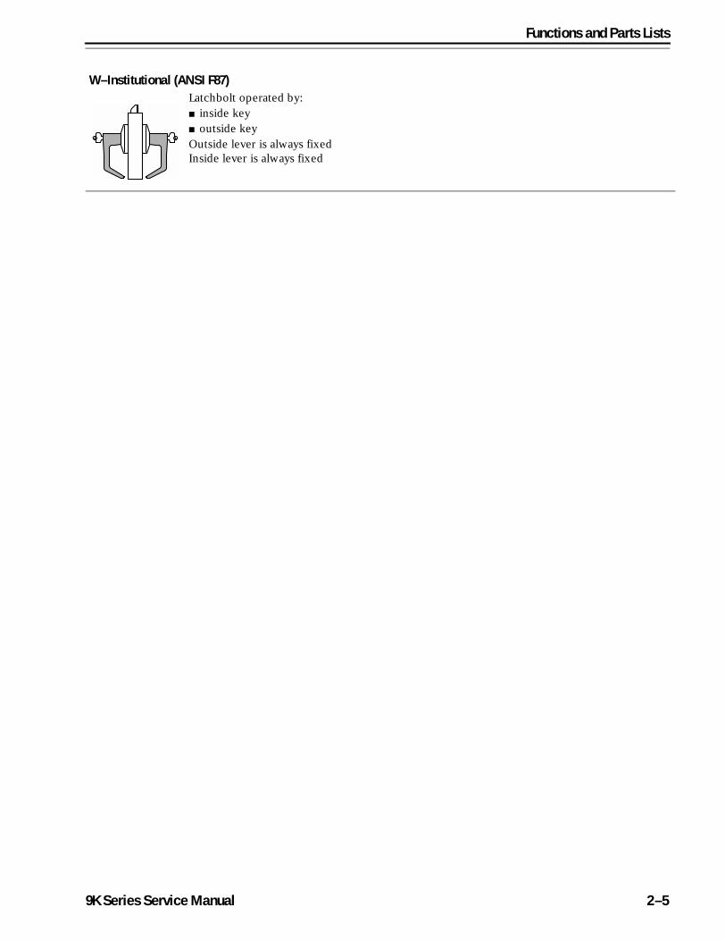
W–Institutional (ANSI F87)Latchbolt operated by:■ inside key■ outside key Outside lever is always fixedInside lever is always fixed
9K Series Service Manual 2–5
Functions and Parts Lists
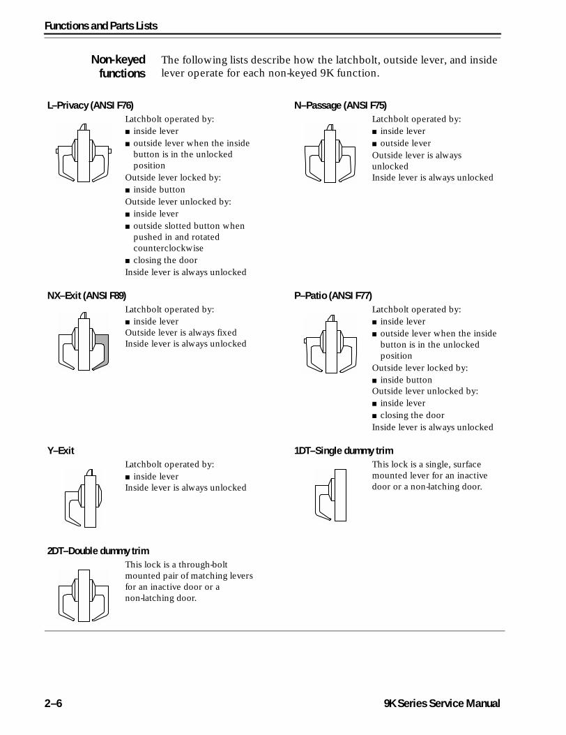
Non-keyedfunctions
The following lists describe how the latchbolt, outside lever, and inside lever operate for each non-keyed 9K function.
L–Privacy (ANSI F76) N–Passage (ANSI F75)Latchbolt operated by:■ inside lever■ outside lever when the inside
button is in the unlocked position
Outside lever locked by:■ inside buttonOutside lever unlocked by:■ inside lever■ outside slotted button when
pushed in and rotated counterclockwise
■ closing the doorInside lever is always unlocked
Latchbolt operated by:■ inside lever ■ outside lever Outside lever is always unlockedInside lever is always unlocked
NX–Exit (ANSI F89) P–Patio (ANSI F77)Latchbolt operated by:■ inside leverOutside lever is always fixedInside lever is always unlocked
Latchbolt operated by:■ inside lever■ outside lever when the inside
button is in the unlocked position
Outside lever locked by:■ inside buttonOutside lever unlocked by:■ inside lever■ closing the doorInside lever is always unlocked
Y–Exit 1DT–Single dummy trimLatchbolt operated by:■ inside leverInside lever is always unlocked
This lock is a single, surface mounted lever for an inactive door or a non-latching door.
2DT–Double dummy trimThis lock is a through-bolt mounted pair of matching levers for an inactive door or a non-latching door.
2–6 9K Series Service Manual
Functions and Parts Lists
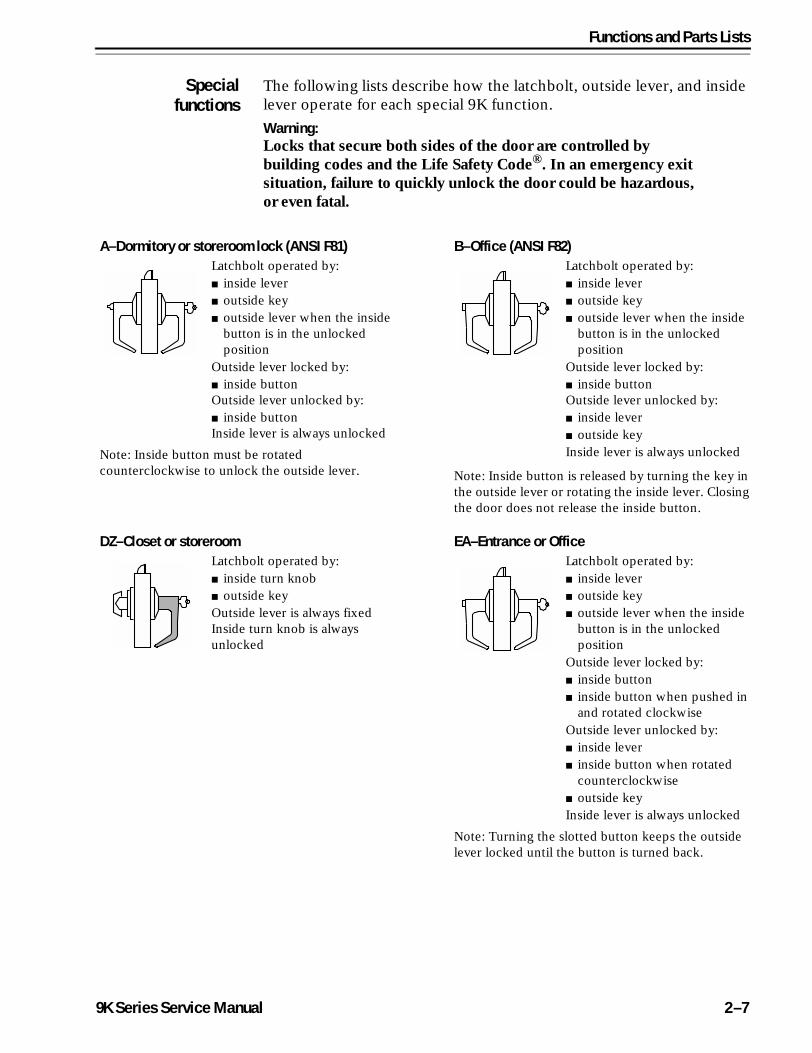
Specialfunctions
The following lists describe how the latchbolt, outside lever, and inside lever operate for each special 9K function.
Warning: Locks that secure both sides of the door are controlled by building codes and the Life Safety Code®. In an emergency exit situation, failure to quickly unlock the door could be hazardous, or even fatal.
A–Dormitory or storeroom lock (ANSI F81) B–Office (ANSI F82)Latchbolt operated by:■ inside lever■ outside key■ outside lever when the inside
button is in the unlocked position
Outside lever locked by:■ inside buttonOutside lever unlocked by:■ inside buttonInside lever is always unlocked
Latchbolt operated by:■ inside lever■ outside key■ outside lever when the inside
button is in the unlocked position
Outside lever locked by:■ inside buttonOutside lever unlocked by:■ inside lever■ outside keyInside lever is always unlockedNote: Inside button must be rotated
counterclockwise to unlock the outside lever. Note: Inside button is released by turning the key in the outside lever or rotating the inside lever. Closing the door does not release the inside button.
DZ–Closet or storeroom EA–Entrance or OfficeLatchbolt operated by:■ inside turn knob■ outside keyOutside lever is always fixedInside turn knob is always unlocked
Latchbolt operated by:■ inside lever■ outside key■ outside lever when the inside
button is in the unlocked position
Outside lever locked by:■ inside button■ inside button when pushed in
and rotated clockwiseOutside lever unlocked by:■ inside lever■ inside button when rotated
counterclockwise■ outside keyInside lever is always unlocked
Note: Turning the slotted button keeps the outside lever locked until the button is turned back.
9K Series Service Manual 2–7
Functions and Parts Lists
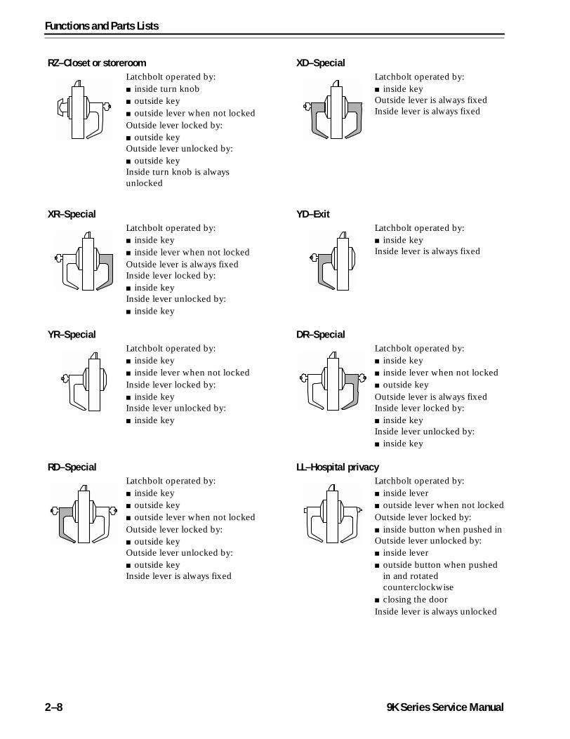
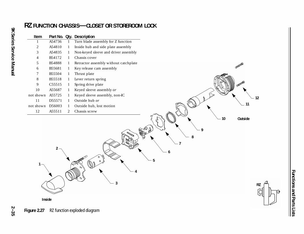
RZ–Closet or storeroom XD–SpecialLatchbolt operated by:■ inside turn knob■ outside key■ outside lever when not lockedOutside lever locked by:■ outside keyOutside lever unlocked by:■ outside keyInside turn knob is always unlocked
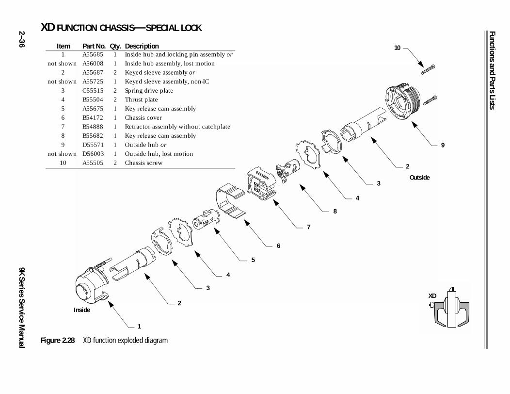
Latchbolt operated by:■ inside keyOutside lever is always fixedInside lever is always fixed
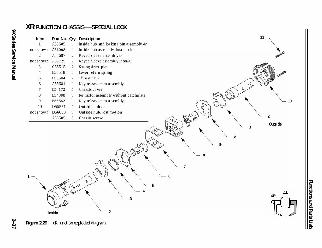
XR–Special YD–ExitLatchbolt operated by:■ inside key■ inside lever when not lockedOutside lever is always fixedInside lever locked by:■ inside keyInside lever unlocked by:■ inside key
Latchbolt operated by:■ inside keyInside lever is always fixed
YR–Special DR–SpecialLatchbolt operated by:■ inside key■ inside lever when not lockedInside lever locked by:■ inside keyInside lever unlocked by:■ inside key
Latchbolt operated by:■ inside key■ inside lever when not locked■ outside keyOutside lever is always fixedInside lever locked by:■ inside keyInside lever unlocked by:■ inside key
RD–Special LL–Hospital privacyLatchbolt operated by:■ inside key■ outside key■ outside lever when not lockedOutside lever locked by:■ outside keyOutside lever unlocked by:■ outside keyInside lever is always fixed
Latchbolt operated by:■ inside lever■ outside lever when not lockedOutside lever locked by:■ inside button when pushed inOutside lever unlocked by:■ inside lever■ outside button when pushed
in and rotated counterclockwise
■ closing the doorInside lever is always unlocked
2–8 9K Series Service Manual
Functions and Parts Lists
Functionsby ANSI
designation
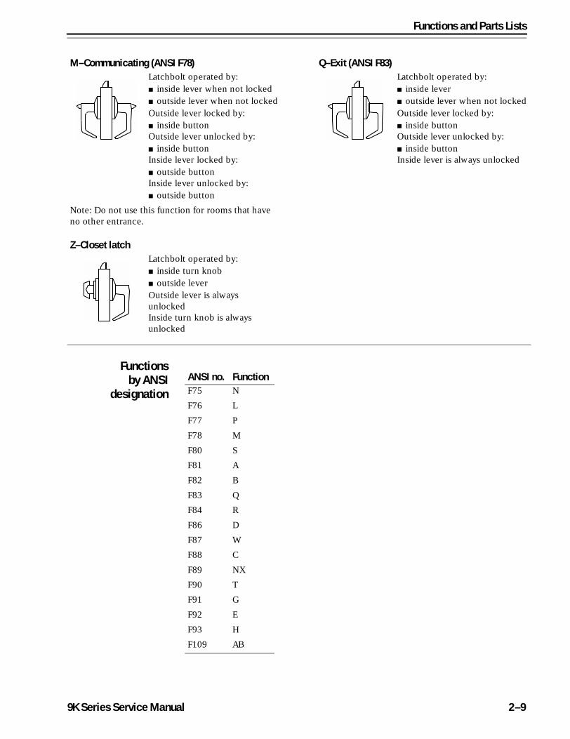
M–Communicating (ANSI F78) Q–Exit (ANSI F83)Latchbolt operated by:■ inside lever when not locked ■ outside lever when not lockedOutside lever locked by:■ inside buttonOutside lever unlocked by:■ inside buttonInside lever locked by:■ outside buttonInside lever unlocked by:■ outside button
Latchbolt operated by:■ inside lever■ outside lever when not lockedOutside lever locked by:■ inside buttonOutside lever unlocked by:■ inside buttonInside lever is always unlocked
Note: Do not use this function for rooms that have no other entrance.
Z–Closet latchLatchbolt operated by:■ inside turn knob ■ outside leverOutside lever is always unlockedInside turn knob is always unlocked
ANSI no. FunctionF75 N
F76 L
F77 P
F78 M
F80 S
F81 A
F82 B
F83 Q
F84 R
F86 D
F87 W
F88 C
F89 NX
F90 T
F91 G
F92 E
F93 H
F109 AB
9K Series Service Manual 2–9
Functions and Parts Lists
2 STANDARD FUNCTIONS
5
4
9
11
10
12
Outside
AB
–1
09K Series Service M
anual
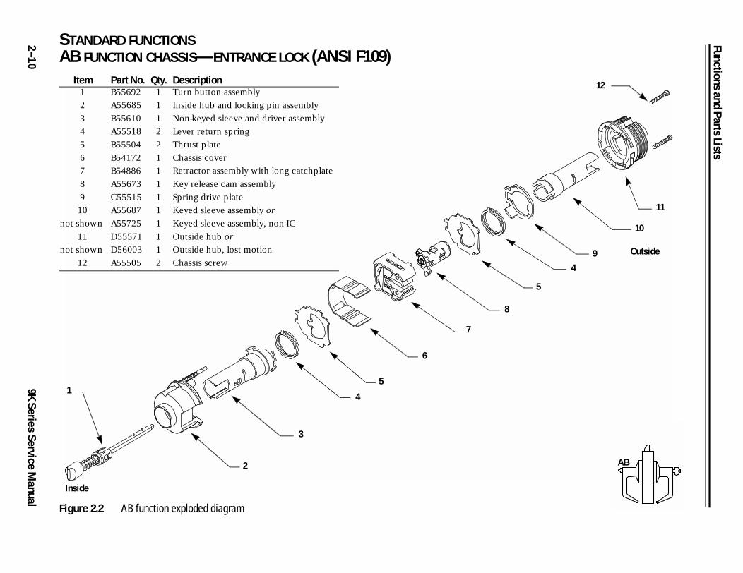
AB FUNCTION CHASSIS—ENTRANCE LOCK (ANSI F109)
Figure 2.2 AB function exploded diagram
1
2
3
4
5
6
7
8
Item Part No. Qty. Description1 B55692 1 Turn button assembly
2 A55685 1 Inside hub and locking pin assembly
3 B55610 1 Non-keyed sleeve and driver assembly
4 A55518 2 Lever return spring
5 B55504 2 Thrust plate
6 B54172 1 Chassis cover
7 B54886 1 Retractor assembly with long catchplate
8 A55673 1 Key release cam assembly
9 C55515 1 Spring drive plate
10
not shown
A55687
A55725
1
1
Keyed sleeve assembly or
Keyed sleeve assembly, non-IC
11
not shown
D55571
D56003
1
1
Outside hub or
Outside hub, lost motion
12 A55505 2 Chassis screw
Inside
Functions and Parts Lists
9K Series Service Manual
2–11
4
3
11
10
12
Outside
C
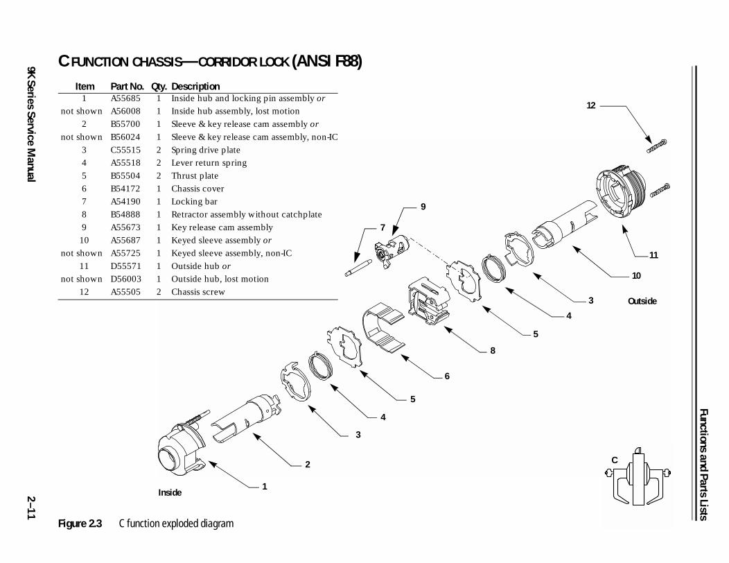
C FUNCTION CHASSIS—CORRIDOR LOCK (ANSI F88)
Figure 2.3 C function exploded diagram
Item Part No. Qty. Description1
not shown
A55685
A56008
1
1
Inside hub and locking pin assembly or
Inside hub assembly, lost motion
2
not shown
B55700
B56024
1
1
Sleeve & key release cam assembly or
Sleeve & key release cam assembly, non-IC
3 C55515 2 Spring drive plate
4 A55518 2 Lever return spring
5 B55504 2 Thrust plate
6 B54172 1 Chassis cover
7 A54190 1 Locking bar
8 B54888 1 Retractor assembly without catchplate
9 A55673 1 Key release cam assembly
10
not shown
A55687
A55725
1
1
Keyed sleeve assembly or
Keyed sleeve assembly, non-IC
11
not shown
D55571
D56003
1
1
Outside hub or
Outside hub, lost motion
12 A55505 2 Chassis screw
6
5
4
3
9
7
8
1
2
5
Inside
Functions and Parts Lists
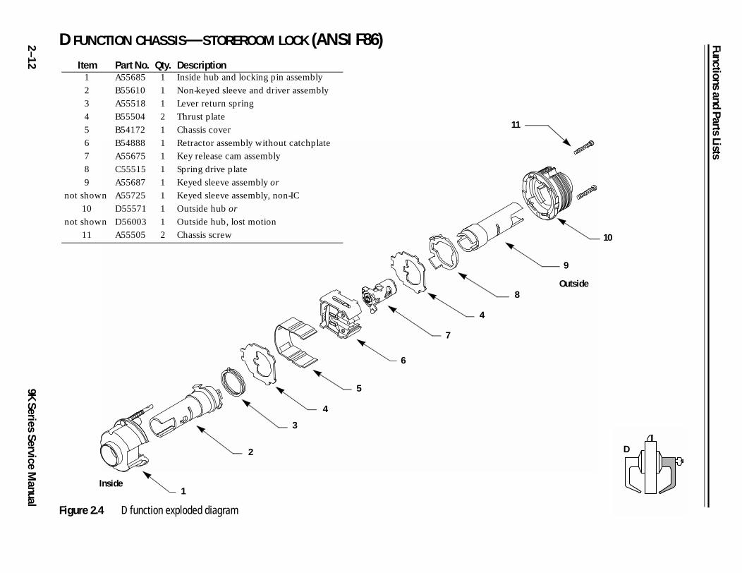
2 D FUNCTION CHASSIS—STOREROOM LOCK (ANSI F86)
10
9
Outside
D
–1
29K Series Service M
anual
Figure 2.4 D function exploded diagram
8
11
Item Part No. Qty. Description1 A55685 1 Inside hub and locking pin assembly
2 B55610 1 Non-keyed sleeve and driver assembly
3 A55518 1 Lever return spring
4 B55504 2 Thrust plate
5 B54172 1 Chassis cover
6 B54888 1 Retractor assembly without catchplate
7 A55675 1 Key release cam assembly
8 C55515 1 Spring drive plate
9
not shown
A55687
A55725
1
1
Keyed sleeve assembly or
Keyed sleeve assembly, non-IC
10
not shown
D55571
D56003
1
1
Outside hub or
Outside hub, lost motion
11 A55505 2 Chassis screw
3
4
5
6
4
Inside
7
2
1
Functions and Parts Lists
9K Series Service Manual
2–13
5
4
9
11
10
12
Outside
E
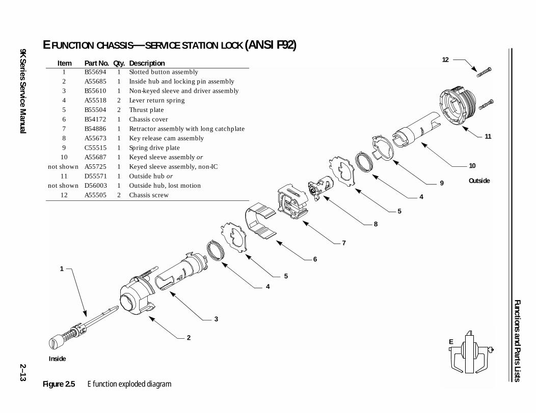
E FUNCTION CHASSIS—SERVICE STATION LOCK (ANSI F92)
Figure 2.5 E function exploded diagram
1
2
3
4
5
6
7
8
Item Part No. Qty. Description1 B55694 1 Slotted button assembly
2 A55685 1 Inside hub and locking pin assembly
3 B55610 1 Non-keyed sleeve and driver assembly
4 A55518 2 Lever return spring
5 B55504 2 Thrust plate
6 B54172 1 Chassis cover
7 B54886 1 Retractor assembly with long catchplate
8 A55673 1 Key release cam assembly
9 C55515 1 Spring drive plate
10
not shown
A55687
A55725
1
1
Keyed sleeve assembly or
Keyed sleeve assembly, non-IC
11
not shown
D55571
D56003
1
1
Outside hub or
Outside hub, lost motion
12 A55505 2 Chassis screw
Inside
Functions and Parts Lists
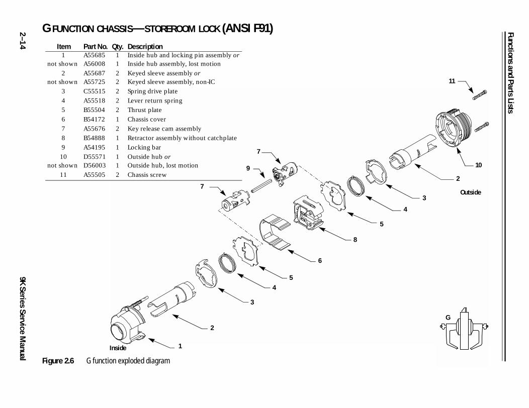
2 G FUNCTION CHASSIS—STOREROOM LOCK (ANSI F91)
5
4
3
10
2
11
Outside
G
–1
49K Series Service M
anual Figure 2.6 G function exploded diagram
1
2
3
45
6
8
7
9
7
Item Part No. Qty. Description1
not shownA55685A56008
11
Inside hub and locking pin assembly orInside hub assembly, lost motion
2not shown
A55687A55725
22
Keyed sleeve assembly orKeyed sleeve assembly, non-IC
3 C55515 2 Spring drive plate
4 A55518 2 Lever return spring
5 B55504 2 Thrust plate
6 B54172 1 Chassis cover
7 A55676 2 Key release cam assembly
8 B54888 1 Retractor assembly without catchplate
9 A54195 1 Locking bar
10not shown
D55571D56003
11
Outside hub orOutside hub, lost motion
11 A55505 2 Chassis screw
Inside
Functions and Parts Lists
9K Series Service Manual
2–15
9
11
10
12
Outside
H, HJ
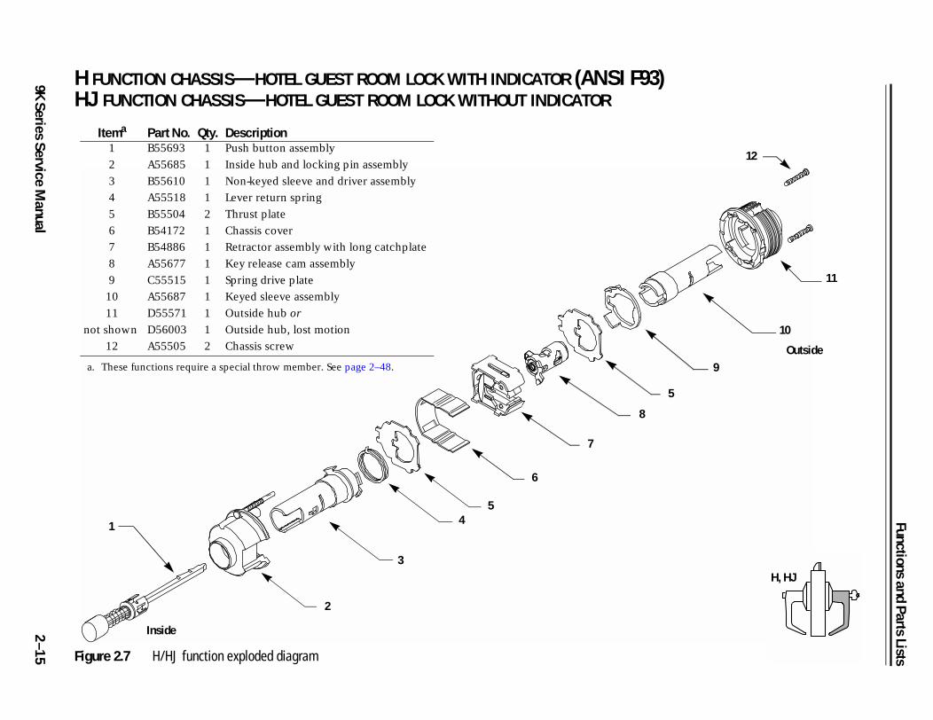
H FUNCTION CHASSIS—HOTEL GUEST ROOM LOCK WITH INDICATOR (ANSI F93)HJ FUNCTION CHASSIS—HOTEL GUEST ROOM LOCK WITHOUT INDICATOR
Figure 2.7 H/HJ function exploded diagram
1
2
3
45
6
7
8
5
Itema
a. These functions require a special throw member. See page 2–48.
Part No. Qty. Description1 B55693 1 Push button assembly
2 A55685 1 Inside hub and locking pin assembly
3 B55610 1 Non-keyed sleeve and driver assembly
4 A55518 1 Lever return spring
5 B55504 2 Thrust plate
6 B54172 1 Chassis cover
7 B54886 1 Retractor assembly with long catchplate
8 A55677 1 Key release cam assembly
9 C55515 1 Spring drive plate
10 A55687 1 Keyed sleeve assembly
11
not shown
D55571
D56003
1
1
Outside hub or
Outside hub, lost motion
12 A55505 2 Chassis screw
Inside
Functions and Parts Lists
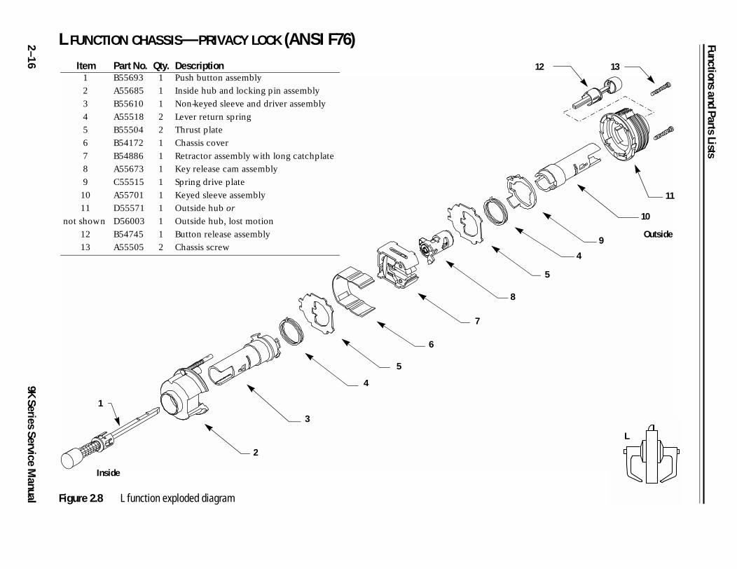
2 L FUNCTION CHASSIS—PRIVACY LOCK (ANSI F76)
5
4
9
11
10
1312
Outside
L
–1
69K Series Service M
anual Figure 2.8 L function exploded diagram
1
2
3
4
5
6
7
8
Item Part No. Qty. Description1 B55693 1 Push button assembly
2 A55685 1 Inside hub and locking pin assembly
3 B55610 1 Non-keyed sleeve and driver assembly
4 A55518 2 Lever return spring
5 B55504 2 Thrust plate
6 B54172 1 Chassis cover
7 B54886 1 Retractor assembly with long catchplate
8 A55673 1 Key release cam assembly
9 C55515 1 Spring drive plate
10 A55701 1 Keyed sleeve assembly
11
not shown
D55571
D56003
1
1
Outside hub or
Outside hub, lost motion
12 B54745 1 Button release assembly
13 A55505 2 Chassis screw
Inside
Functions and Parts Lists
9K Series Service Manual
2–17
7
e
N
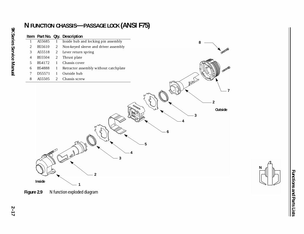
N FUNCTION CHASSIS—PASSAGE LOCK (ANSI F75)
Figure 2.9 N function exploded diagram
1
2
34
5
6
43
2
8
Item Part No. Qty. Description1 A55685 1 Inside hub and locking pin assembly
2 B55610 2 Non-keyed sleeve and driver assembly
3 A55518 2 Lever return spring
4 B55504 2 Thrust plate
5 B54172 1 Chassis cover
6 B54888 1 Retractor assembly without catchplate
7 D55571 1 Outside hub
8 A55505 2 Chassis screw
Inside
Outsid
Functions and Parts Lists
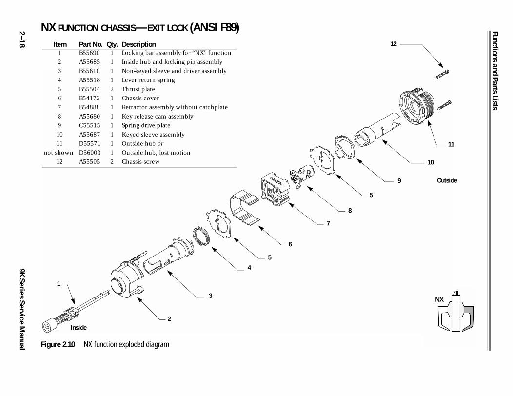
2 NX FUNCTION CHASSIS—EXIT LOCK (ANSI F89)
5
9
11
10
12
Outside
NX
–1
89K Series Service M
anual Figure 2.10 NX function exploded diagram
1
2
3
4
5
6
7
8
Item Part No. Qty. Description1 B55690 1 Locking bar assembly for “NX” function
2 A55685 1 Inside hub and locking pin assembly
3 B55610 1 Non-keyed sleeve and driver assembly
4 A55518 1 Lever return spring
5 B55504 2 Thrust plate
6 B54172 1 Chassis cover
7 B54888 1 Retractor assembly without catchplate
8 A55680 1 Key release cam assembly
9 C55515 1 Spring drive plate
10 A55687 1 Keyed sleeve assembly
11
not shown
D55571
D56003
1
1
Outside hub or
Outside hub, lost motion
12 A55505 2 Chassis screw
Inside
Functions and Parts Lists
9K Series Service Manual
2–19
4
9
11
12
10
Outside
P
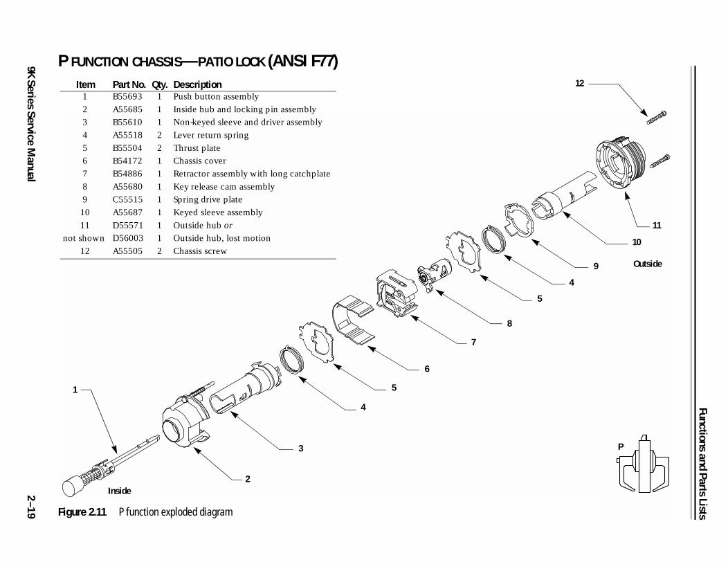
P FUNCTION CHASSIS—PATIO LOCK (ANSI F77)
Figure 2.11 P function exploded diagram
1
2
3
4
5
6
7
8
5
Item Part No. Qty. Description1 B55693 1 Push button assembly
2 A55685 1 Inside hub and locking pin assembly
3 B55610 1 Non-keyed sleeve and driver assembly
4 A55518 2 Lever return spring
5 B55504 2 Thrust plate
6 B54172 1 Chassis cover
7 B54886 1 Retractor assembly with long catchplate
8 A55680 1 Key release cam assembly
9 C55515 1 Spring drive plate
10 A55687 1 Keyed sleeve assembly
11
not shown
D55571
D56003
1
1
Outside hub or
Outside hub, lost motion
12 A55505 2 Chassis screw
Inside
Functions and Parts Lists
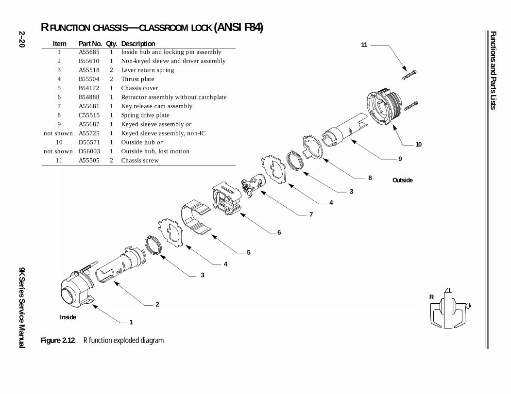
2 R FUNCTION CHASSIS—CLASSROOM LOCK (ANSI F84)
8
10
9
1
Outside
R
–2
09K Series Service M
anual Figure 2.12 R function exploded diagram
1
2
3
4
5
6
7
4
3
1Item Part No. Qty. Description1 A55685 1 Inside hub and locking pin assembly
2 B55610 1 Non-keyed sleeve and driver assembly
3 A55518 2 Lever return spring
4 B55504 2 Thrust plate
5 B54172 1 Chassis cover
6 B54888 1 Retractor assembly without catchplate
7 A55681 1 Key release cam assembly
8 C55515 1 Spring drive plate
9
not shown
A55687
A55725
1
1
Keyed sleeve assembly or
Keyed sleeve assembly, non-IC
10
not shown
D55571
D56003
1
1
Outside hub or
Outside hub, lost motion
11 A55505 2 Chassis screw
Inside
Functions and Parts Lists
9K Series Service Manual
2–21
4
3
9
2
10
Outside
S
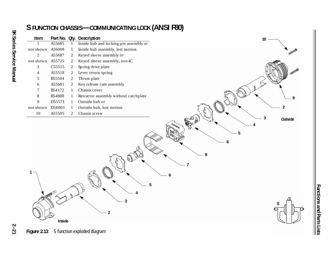
S FUNCTION CHASSIS—COMMUNICATING LOCK (ANSI F80)
Figure 2.13 S function exploded diagram
1
2
3
5
6
7
8
6
5
4
Item Part No. Qty. Description1
not shown
A55685
A56008
1
1
Inside hub and locking pin assembly or
Inside hub assembly, lost motion
2
not shown
A55687
A55725
2
2
Keyed sleeve assembly or
Keyed sleeve assembly, non-IC
3 C55515 2 Spring drive plate
4 A55518 2 Lever return spring
5 B55504 2 Thrust plate
6 A55681 2 Key release cam assembly
7 B54172 1 Chassis cover
8 B54888 1 Retractor assembly without catchplate
9
not shown
D55571
D56003
1
1
Outside hub or
Outside hub, lost motion
10 A55505 2 Chassis screw
Inside

Functions and Parts Lists
2 T FUNCTION CHASSIS—DORMITORY LOCK (ANSI F90)
5
4
9
11
10
12
Outside
T
–2
29K Series Service M
anual Figure 2.14 T function exploded diagram
1
2
3
4
5
6
7
8
Item Part No. Qty. Description1 B55693 1 Push button assembly
2 A55685 1 Inside hub and locking pin assembly
3 B55610 1 Non-keyed sleeve and driver assembly
4 A55518 2 Lever return spring
5 B55504 2 Thrust plate
6 B54172 1 Chassis cover
7 B54886 1 Retractor assembly with long catchplate
8 A55681 1 Key release cam assembly
9 C55515 1 Spring drive plate
10
not shown
A55687
A55725
1
1
Keyed sleeve assembly or
Keyed sleeve assembly, non-IC
11
not shown
D55571
D56003
1
1
Outside hub or
Outside hub, lost motion
12 A55505 2 Chassis screw
Inside
Functions and Parts Lists
9K Series Service Manual
2–23
8
2
Outside
W
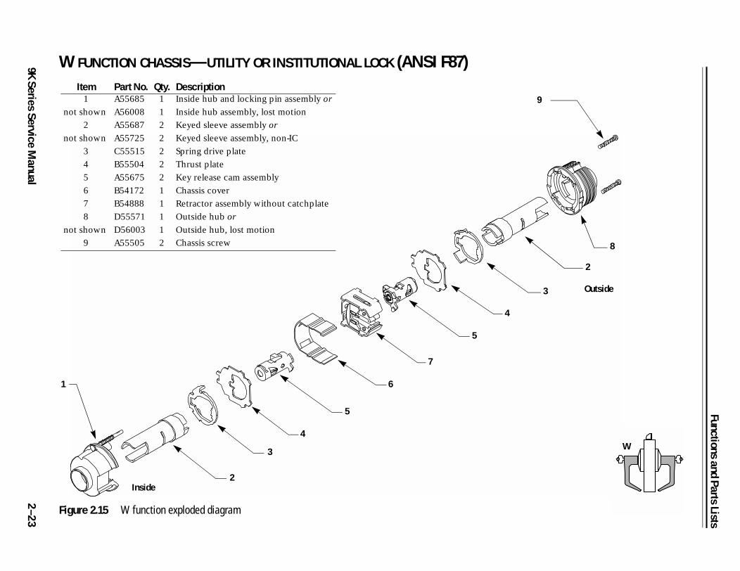
W FUNCTION CHASSIS—UTILITY OR INSTITUTIONAL LOCK (ANSI F87)
Figure 2.15 W function exploded diagram
1
2
3
4
6
7
5
4
3
9
5
Item Part No. Qty. Description1
not shown
A55685
A56008
1
1
Inside hub and locking pin assembly or
Inside hub assembly, lost motion
2
not shown
A55687
A55725
2
2
Keyed sleeve assembly or
Keyed sleeve assembly, non-IC
3 C55515 2 Spring drive plate
4 B55504 2 Thrust plate
5 A55675 2 Key release cam assembly
6 B54172 1 Chassis cover
7 B54888 1 Retractor assembly without catchplate
8
not shown
D55571
D56003
1
1
Outside hub or
Outside hub, lost motion
9 A55505 2 Chassis screw
Inside
Functions and Parts Lists
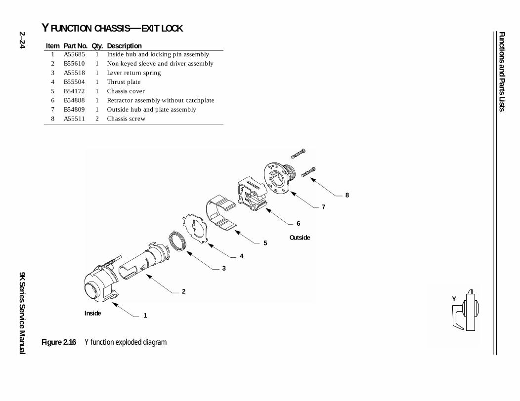
2 Y FUNCTION CHASSIS—EXIT LOCK
Y
–2
49K Series Service M
anual
Figure 2.16 Y function exploded diagram
1
2
3
4
5
6
7
8
Item Part No. Qty. Description1 A55685 1 Inside hub and locking pin assembly
2 B55610 1 Non-keyed sleeve and driver assembly
3 A55518 1 Lever return spring
4 B55504 1 Thrust plate
5 B54172 1 Chassis cover
6 B54888 1 Retractor assembly without catchplate
7 B54809 1 Outside hub and plate assembly
8 A55511 2 Chassis screw
Inside
Outside
Functions and Parts Lists
9K Series Service Manual
2–25
12
4
9
10
11
Outside
A
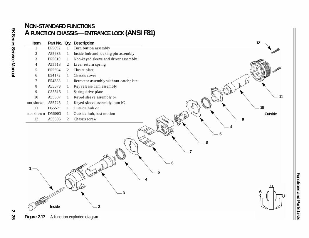
NON-STANDARD FUNCTIONSA FUNCTION CHASSIS—ENTRANCE LOCK (ANSI F81)
Figure 2.17 A function exploded diagram
Item Part No. Qty. Description1 B55692 1 Turn button assembly
2 A55685 1 Inside hub and locking pin assembly
3 B55610 1 Non-keyed sleeve and driver assembly
4 A55518 2 Lever return spring
5 B55504 2 Thrust plate
6 B54172 1 Chassis cover
7 B54888 1 Retractor assembly without catchplate
8 A55673 1 Key release cam assembly
9 C55515 1 Spring drive plate
10
not shown
A55687
A55725
1
1
Keyed sleeve assembly or
Keyed sleeve assembly, non-IC
11
not shown
D55571
D56003
1
1
Outside hub or
Outside hub, lost motion
12 A55505 2 Chassis screw
1
2
3
4
5
6
7
8
5
Inside
Functions and Parts Lists
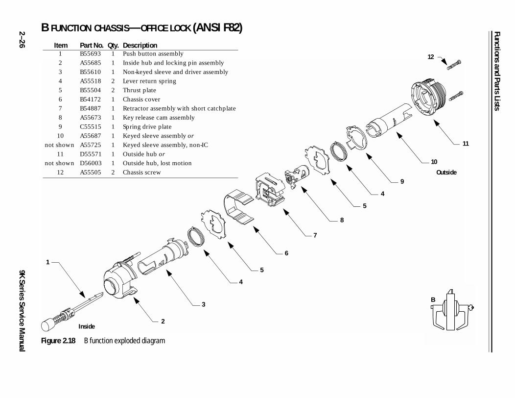
2 B FUNCTION CHASSIS—OFFICE LOCK (ANSI F82)
12
4
9
10
11
Outside
B
–2
69K Series Service M
anual
Figure 2.18 B function exploded diagram
Item Part No. Qty. Description1 B55693 1 Push button assembly
2 A55685 1 Inside hub and locking pin assembly
3 B55610 1 Non-keyed sleeve and driver assembly
4 A55518 2 Lever return spring
5 B55504 2 Thrust plate
6 B54172 1 Chassis cover
7 B54887 1 Retractor assembly with short catchplate
8 A55673 1 Key release cam assembly
9 C55515 1 Spring drive plate
10
not shown
A55687
A55725
1
1
Keyed sleeve assembly or
Keyed sleeve assembly, non-IC
11
not shown
D55571
D56003
1
1
Outside hub or
Outside hub, lost motion
12 A55505 2 Chassis screw
1
3
4
6
7
8
5
2
5
Inside
Functions and Parts Lists
9K Series Service Manual
2–27
11
3
2
10
Outside
DR
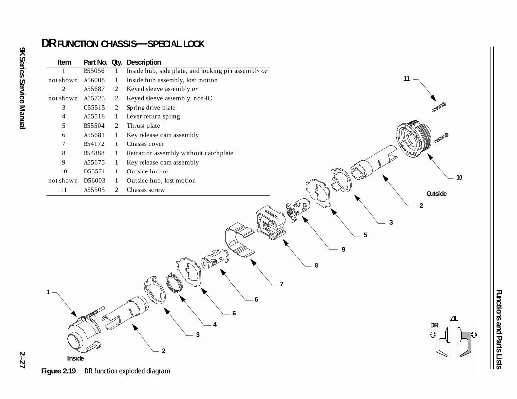
DR FUNCTION CHASSIS—SPECIAL LOCK
Figure 2.19 DR function exploded diagram
Item Part No. Qty. Description1
not shown
B55056
A56008
1
1
Inside hub, side plate, and locking pin assembly or
Inside hub assembly, lost motion
2
not shown
A55687
A55725
2
2
Keyed sleeve assembly or
Keyed sleeve assembly, non-IC
3 C55515 2 Spring drive plate
4 A55518 1 Lever return spring
5 B55504 2 Thrust plate
6 A55681 1 Key release cam assembly
7 B54172 1 Chassis cover
8 B54888 1 Retractor assembly without catchplate
9 A55675 1 Key release cam assembly
10
not shown
D55571
D56003
1
1
Outside hub or
Outside hub, lost motion
11 A55505 2 Chassis screw
1
3
4
5
7
8
9
5
2
6
Inside
Functions and Parts Lists
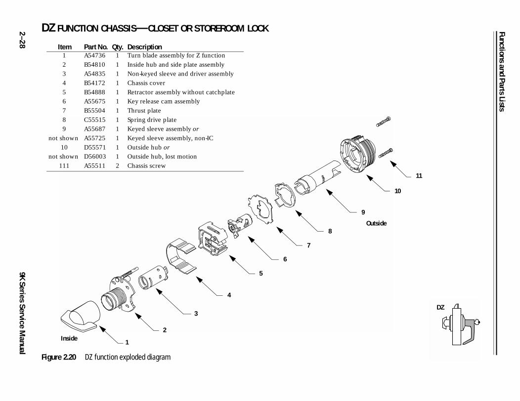
2 DZ FUNCTION CHASSIS—CLOSET OR STOREROOM LOCK
10
11
utside
DZ
–2
89K Series Service M
anual
Figure 2.20 DZ function exploded diagram
Item Part No. Qty. Description1 A54736 1 Turn blade assembly for Z function
2 B54810 1 Inside hub and side plate assembly
3 A54835 1 Non-keyed sleeve and driver assembly
4 B54172 1 Chassis cover
5 B54888 1 Retractor assembly without catchplate
6 A55675 1 Key release cam assembly
7 B55504 1 Thrust plate
8 C55515 1 Spring drive plate
9
not shown
A55687
A55725
1
1
Keyed sleeve assembly or
Keyed sleeve assembly, non-IC
10
not shown
D55571
D56003
1
1
Outside hub or
Outside hub, lost motion
111 A55511 2 Chassis screw
4
5
7
8
6
2
3
Inside
O
9
1

Functions and Parts Lists
9K Series Service Manual
2–29
12
9
10
11
Outside
EA
EA FUNCTION CHASSIS—ENTRANCE OR OFFICE LOCK
Figure 2.21 EA function exploded diagram
Item Part No. Qty. Description1 B55694 1 Slotted button assembly
2 A55685 1 Inside hub and locking pin assembly
3 B55610 1 Non-keyed sleeve and driver assembly
4 B55518 2 Lever return spring
5 B55504 2 Thrust plate
6 B54172 1 Chassis cover
7 B54887 1 Retractor assembly with short catchplate
8 A55673 1 Key release cam assembly
9 C55515 1 Spring drive plate
10
not shown
A55687
A55725
1
1
Keyed sleeve assembly or
Keyed sleeve assembly, non-IC
11
not shown
D55571
D56003
1
1
Outside hub or
Outside hub, lost motion
12 A55505 2 Chassis screw
1
3
4
5
6
7
8
5
4
2Inside
Functions and Parts Lists
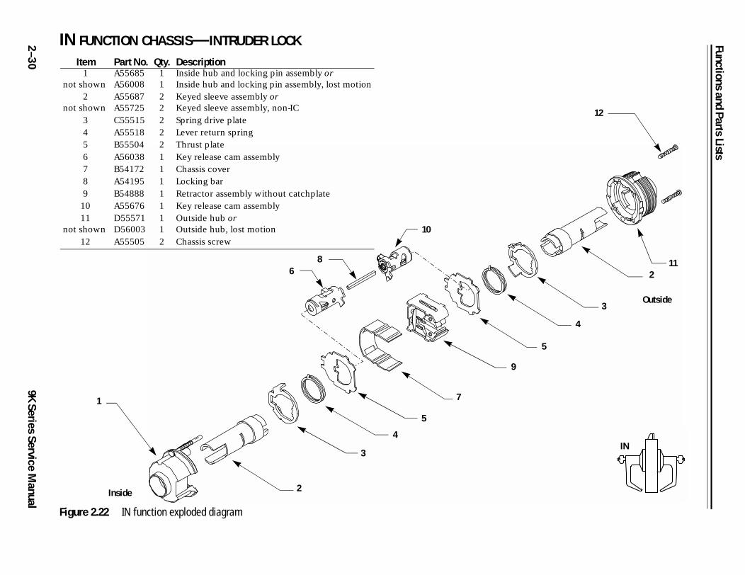
2 IN FUNCTION CHASSIS—INTRUDER LOCK
5
4
3
112
12
Outside
IN
–3
09K Series Service M
anual
Figure 2.22 IN function exploded diagram
Item Part No. Qty. Description1
not shownA55685A56008
11
Inside hub and locking pin assembly orInside hub and locking pin assembly, lost motion
2not shown
A55687A55725
22
Keyed sleeve assembly orKeyed sleeve assembly, non-IC
3 C55515 2 Spring drive plate4 A55518 2 Lever return spring5 B55504 2 Thrust plate6 A56038 1 Key release cam assembly7 B54172 1 Chassis cover8 A54195 1 Locking bar9 B54888 1 Retractor assembly without catchplate
10 A55676 1 Key release cam assembly11
not shownD55571D56003
11
Outside hub orOutside hub, lost motion
12 A55505 2 Chassis screw
1
2
3
4
5
7
9
10
86
Inside
Functions and Parts Lists
9K Series Service Manual
2–31
9
11
10
Outside
314
LL
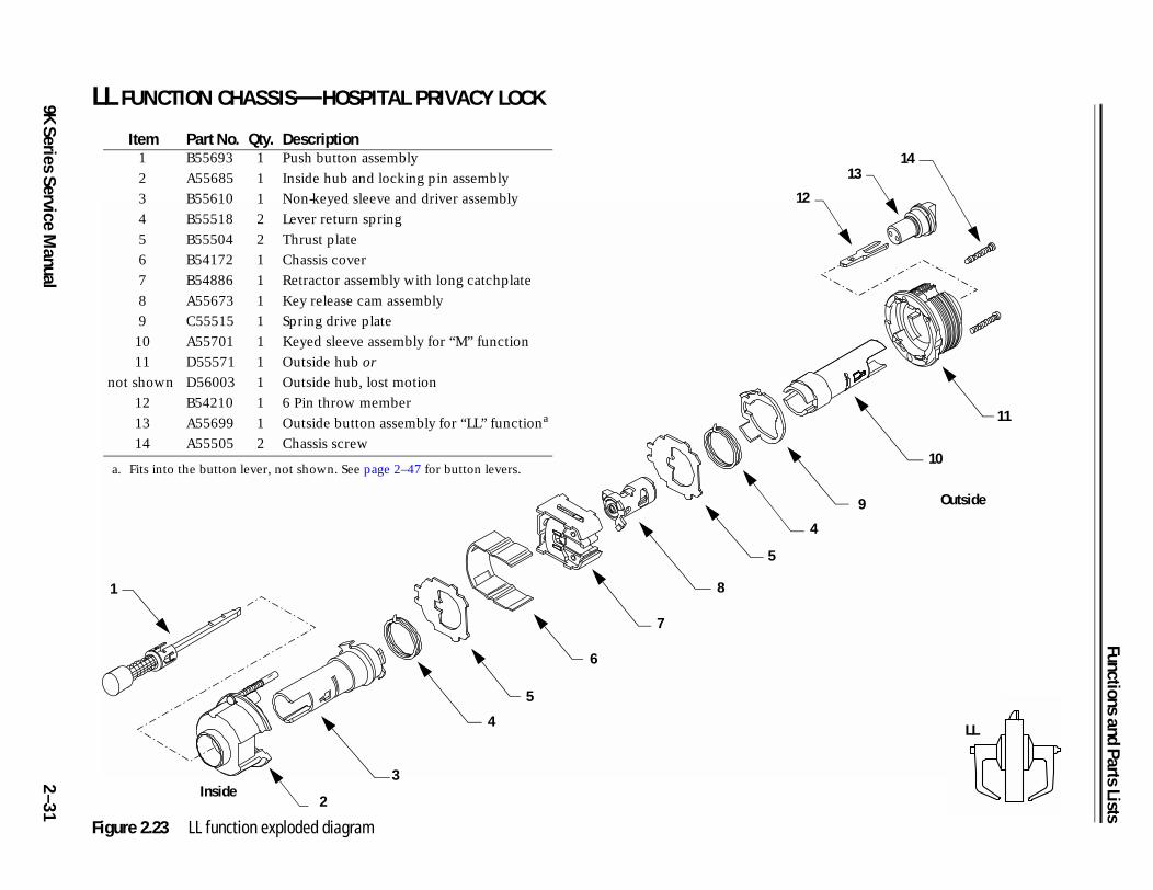
LL FUNCTION CHASSIS—HOSPITAL PRIVACY LOCK
Figure 2.23 LL function exploded diagram
Item Part No. Qty. Description1 B55693 1 Push button assembly
2 A55685 1 Inside hub and locking pin assembly
3 B55610 1 Non-keyed sleeve and driver assembly
4 B55518 2 Lever return spring
5 B55504 2 Thrust plate
6 B54172 1 Chassis cover
7 B54886 1 Retractor assembly with long catchplate
8 A55673 1 Key release cam assembly
9 C55515 1 Spring drive plate
10 A55701 1 Keyed sleeve assembly for “M” function
11
not shown
D55571
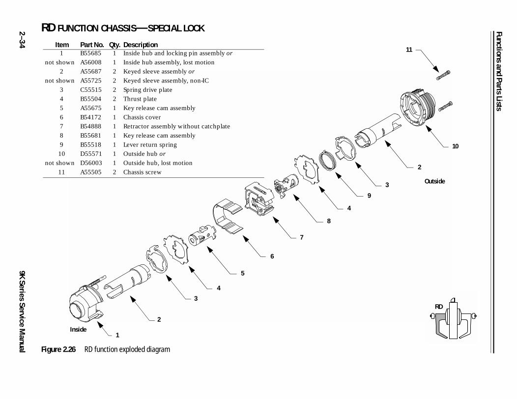
D56003
1
1
Outside hub or
Outside hub, lost motion
12 B54210 1 6 Pin throw member
13 A55699 1 Outside button assembly for “LL” functiona
14 A55505 2 Chassis screw
a. Fits into the button lever, not shown. See page 2–47 for button levers.
1
3
4
5
6
7
8
5
4
2Inside
1
12
Functions and Parts Lists
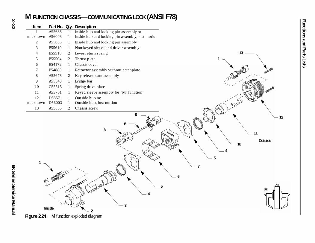
2 M FUNCTION CHASSIS—COMMUNICATING LOCK (ANSI F78)
4
10
13
11
12
Outside
M
–3
29K Series Service M
anual
Figure 2.24 M function exploded diagram
Item Part No. Qty. Description1
not shownA55685A56008
11
Inside hub and locking pin assembly orInside hub and locking pin assembly, lost motion
2 A55685 1 Inside hub and locking pin assembly
3 B55610 1 Non-keyed sleeve and driver assembly
4 B55518 2 Lever return spring
5 B55504 2 Thrust plate
6 B54172 1 Chassis cover
7 B54888 1 Retractor assembly without catchplate
8 A55678 2 Key release cam assembly
9 A55540 1 Bridge bar
10 C55515 1 Spring drive plate
11 A55701 1 Keyed sleeve assembly for “M” function
12not shown
D55571D56003
11
Outside hub orOutside hub, lost motion
13 A55505 2 Chassis screw
1
23
4
5
6
7
5
8
98
1
Inside
Functions and Parts Lists
9K Series Service Manual
2–33
12
9
10
11
Outside
Q
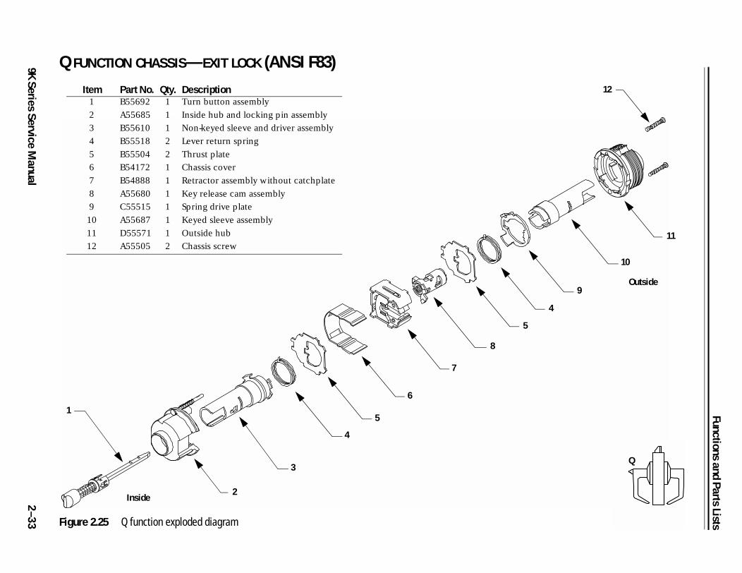
Q FUNCTION CHASSIS—EXIT LOCK (ANSI F83)
Figure 2.25 Q function exploded diagram
Item Part No. Qty. Description1 B55692 1 Turn button assembly
2 A55685 1 Inside hub and locking pin assembly
3 B55610 1 Non-keyed sleeve and driver assembly
4 B55518 2 Lever return spring
5 B55504 2 Thrust plate
6 B54172 1 Chassis cover
7 B54888 1 Retractor assembly without catchplate
8 A55680 1 Key release cam assembly
9 C55515 1 Spring drive plate
10 A55687 1 Keyed sleeve assembly
11 D55571 1 Outside hub
12 A55505 2 Chassis screw
1
3
4
5
6
7
8
5
4
2Inside
Functions and Parts Lists
2 RD FUNCTION CHASSIS—SPECIAL LOCK
11
3
2
10
Outside
9
RD
–3
49K Series Service M
anual Figure 2.26 RD function exploded diagram
Item Part No. Qty. Description1
not shown
B55685
A56008
1
1
Inside hub and locking pin assembly or
Inside hub assembly, lost motion
2
not shown
A55687
A55725
2
2
Keyed sleeve assembly or
Keyed sleeve assembly, non-IC
3 C55515 2 Spring drive plate
4 B55504 2 Thrust plate
5 A55675 1 Key release cam assembly
6 B54172 1 Chassis cover
7 B54888 1 Retractor assembly without catchplate
8 B55681 1 Key release cam assembly
9 B55518 1 Lever return spring
10
not shown
D55571
D56003
1
1
Outside hub or
Outside hub, lost motion
11 A55505 2 Chassis screw
3
4
5
6
7
8
4
2
1Inside
Functions and Parts Lists
9K Series Service Manual
2–35
11
12
Outside
RZ
RZ FUNCTION CHASSIS—CLOSET OR STOREROOM LOCK
Figure 2.27 RZ function exploded diagram
Item Part No. Qty. Description1 A54736 1 Turn blade assembly for Z function
2 A54810 1 Inside hub and side plate assembly
3 A54835 1 Non-keyed sleeve and driver assembly
4 B54172 1 Chassis cover
5 B54888 1 Retractor assembly without catchplate
6 B55681 1 Key release cam assembly
7 B55504 1 Thrust plate
8 B55518 1 Lever return spring
9 C55515 1 Spring drive plate
10
not shown
A55687
A55725
1
1
Keyed sleeve assembly or
Keyed sleeve assembly, non-IC
11
not shown
D55571
D56003
1
1
Outside hub or
Outside hub, lost motion
12 A55511 2 Chassis screw
2
4
5
6
7
8
9
10
3
Inside
1
Functions and Parts Lists
2 XD FUNCTION CHASSIS—SPECIAL LOCK
10
3
2
9
Outside
XD
–3
69K Series Service M
anual Figure 2.28 XD function exploded diagram
Item Part No. Qty. Description1
not shown
A55685
A56008
1
1
Inside hub and locking pin assembly or
Inside hub assembly, lost motion
2
not shown
A55687
A55725
2
1
Keyed sleeve assembly or
Keyed sleeve assembly, non-IC
3 C55515 2 Spring drive plate
4 B55504 2 Thrust plate
5 A55675 1 Key release cam assembly
6 B54172 1 Chassis cover
7 B54888 1 Retractor assembly without catchplate
8 B55682 1 Key release cam assembly
9
not shown
D55571
D56003
1
1
Outside hub or
Outside hub, lost motion
10 A55505 2 Chassis screw
2
3
4
5
6
7
8
4
1
Inside
Functions and Parts Lists
9K Series Service Manual
2–37
11
3
2
10
Outside
XR
XR FUNCTION CHASSIS—SPECIAL LOCK
Figure 2.29 XR function exploded diagram
Item Part No. Qty. Description1
not shown
A55685
A56008
1
1
Inside hub and locking pin assembly or
Inside hub assembly, lost motion
2
not shown
A55687
A55725
2
2
Keyed sleeve assembly or
Keyed sleeve assembly, non-IC
3 C55515 2 Spring drive plate
4 B55518 1 Lever return spring
5 B55504 2 Thrust plate
6 A55681 1 Key release cam assembly
7 B54172 1 Chassis cover
8 B54888 1 Retractor assembly without catchplate
9 B55682 1 Key release cam assembly
10
not shown
D55571
D56003
1
1
Outside hub or
Outside hub, lost motion
11 A55505 2 Chassis screw
1
3
5
6
7
8
9
5
2
4
Inside
Functions and Parts Lists
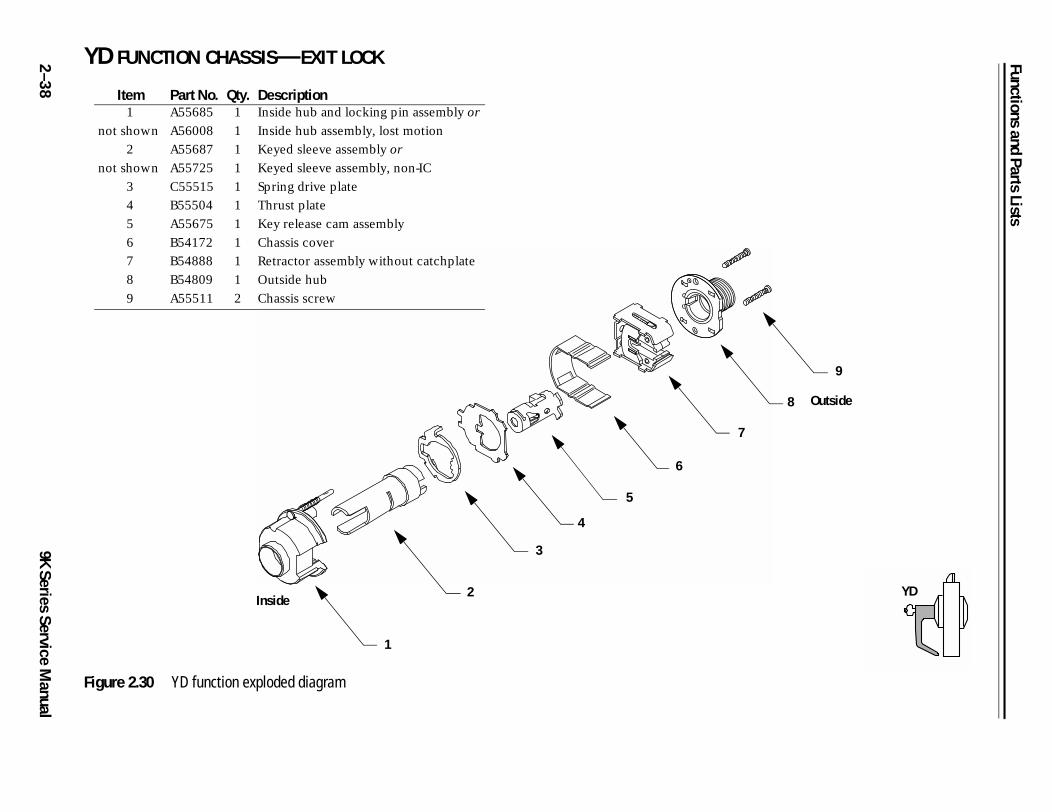
2 YD FUNCTION CHASSIS—EXIT LOCK
8
9
Outside
YD
–3
89K Series Service M
anual
Figure 2.30 YD function exploded diagram
Item Part No. Qty. Description1
not shown
A55685
A56008
1
1
Inside hub and locking pin assembly or
Inside hub assembly, lost motion
2
not shown
A55687
A55725
1
1
Keyed sleeve assembly or
Keyed sleeve assembly, non-IC
3 C55515 1 Spring drive plate
4 B55504 1 Thrust plate
5 A55675 1 Key release cam assembly
6 B54172 1 Chassis cover
7 B54888 1 Retractor assembly without catchplate
8 B54809 1 Outside hub
9 A55511 2 Chassis screw
1
2
3
4
5
6
7
Inside
Functions and Parts Lists
9K Series Service Manual
2–39
8
9
10
Outside
YR
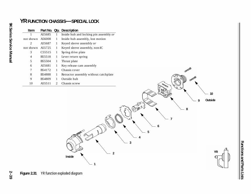
YR FUNCTION CHASSIS—SPECIAL LOCK
Figure 2.31 YR function exploded diagram
Item Part No. Qty. Description1
not shown
A55685
A56008
1
1
Inside hub and locking pin assembly or
Inside hub assembly, lost motion
2
not shown
A55687
A55725
1
1
Keyed sleeve assembly or
Keyed sleeve assembly, non-IC
3 C55515 1 Spring drive plate
4 B55518 1 Lever return spring
5 B55504 1 Thrust plate
6 A55681 1 Key release cam assembly
7 B54172 1 Chassis cover
8 B54888 1 Retractor assembly without catchplate
9 B54809 1 Outside hub
10 A55511 2 Chassis screw
1
2
3
4
6
7
5
Inside
Functions and Parts Lists
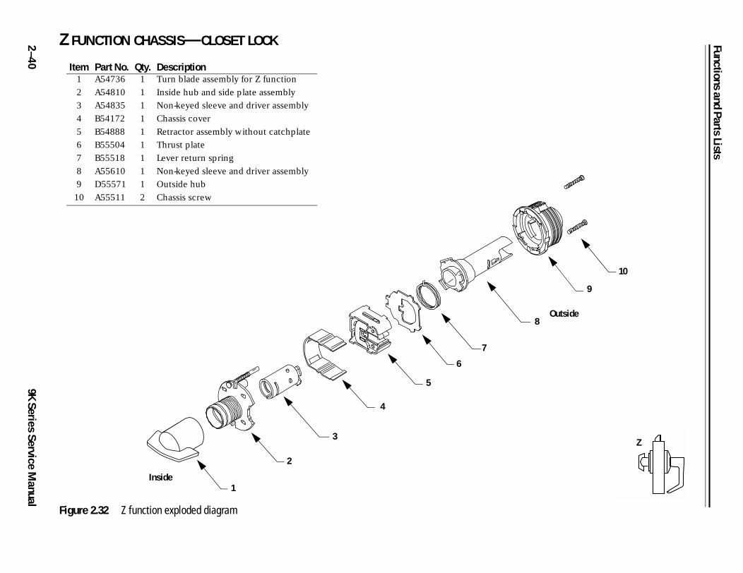
2 Z FUNCTION CHASSIS—CLOSET LOCK
10
8
9
Outside
Z
–4
09K Series Service M
anual
Figure 2.32 Z function exploded diagram
Item Part No. Qty. Description1 A54736 1 Turn blade assembly for Z function
2 A54810 1 Inside hub and side plate assembly
3 A54835 1 Non-keyed sleeve and driver assembly
4 B54172 1 Chassis cover
5 B54888 1 Retractor assembly without catchplate
6 B55504 1 Thrust plate
7 B55518 1 Lever return spring
8 A55610 1 Non-keyed sleeve and driver assembly
9 D55571 1 Outside hub
10 A55511 2 Chassis screw
2
3
4
5
6
7
Inside1
Functions and Parts Lists
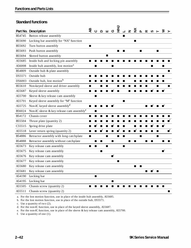
FUNCTION CONVERSIONIf you want to convert the function of an existing 9K Lock, use the following tables to determine the internal parts that you need. Unless otherwise noted, a quantity of one is used for each part.
9K Series Service Manual 2–41
Functions and Parts Lists
Standard functions
Part No. Description AB
C D E G H/H
J
L N NX
P R S T W Y
B54745 Button release assembly ■
B55690 Locking bar assembly for “NX” function ■
B55692 Turn button assembly ■
B55693 Push button assembly ■ ■ ■ ■
B55694 Slotted button assembly ■
A55685 Inside hub and locking pin assembly ■ ■ ■ ■ ■ ■ ■ ■ ■ ■ ■ ■ ■ ■ ■
A56008 Inside hub assembly, lost motiona■ ■ ■ ■
B54809 Outside hub & plate assembly ■
D55571 Outside hub ■ ■ ■ ■ ■ ■ ■ ■ ■ ■ ■ ■ ■ ■
D56003 Outside hub, lost motionb■ ■ ■ ■ ■ ■ ■ ■ ■ ■ ■ ■ ■
B55610 Non-keyed sleeve and driver assembly ■ ■ ■ ■ ■ ■ ■ ■ ■ ■ ■
A55687 Keyed sleeve assembly ■ ■ ■ ■ ■c
■ ■ ■ ■ ■ ■c
■ ■c
A55700 Sleeve & key release cam assembly ■
A55701 Keyed sleeve assembly for “M” function ■
A55725 Non-IC keyed sleeve assemblyd■ ■ ■ ■ ■
c■ ■
c■ ■
c
B56024 Non-IC sleeve & key release cam assemblye■
B54172 Chassis cover ■ ■ ■ ■ ■ ■ ■ ■ ■ ■ ■ ■ ■ ■ ■
B55504 Thrust plate (quantity 2) ■ ■ ■ ■ ■ ■ ■ ■ ■ ■ ■ ■ ■ ■ ■f
C55515 Spring drive plate ■ ■c
■ ■ ■c
■ ■ ■ ■ ■ ■c
■ ■c
A55518 Lever return spring (quantity 2) ■ ■ ■f
■ ■ ■f
■ ■ ■f
■ ■ ■ ■ ■f
B54886 Retractor assembly with long catchplate ■ ■ ■ ■ ■ ■
B54888 Retractor assembly without catchplate ■ ■ ■ ■ ■ ■ ■ ■ ■
A55673 Key release cam assembly ■ ■ ■ ■
A55675 Key release cam assembly ■ ■c
A55676 Key release cam assembly ■c
A55677 Key release cam assembly ■
A55680 Key release cam assembly ■ ■
A55681 Key release cam assembly ■ ■c
■
A54190 Locking bar ■
A54195 Locking bar ■
A55505 Chassis screw (quantity 2) ■ ■ ■ ■ ■ ■ ■ ■ ■ ■ ■ ■ ■ ■
A55511 Chassis screw (quantity 2) ■
a. For the lost motion function, use in place of the inside hub assembly, A55685.b. For the lost motion function, use in place of the outside hub, D55571.c. Use a quantity of two (2).d. For the non-IC function, use in place of the keyed sleeve assembly, A55687.e. For the non-IC function, use in place of the sleeve & key release cam assembly, A55700.f. Use a quantity of one (1).
2–42 9K Series Service Manual
Functions and Parts Lists
Z
■
■
■
■
■f
■f
■
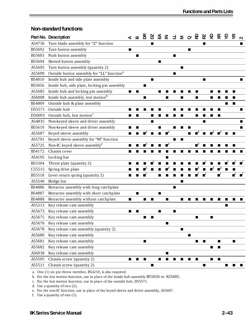
Non-standard functionsPart No. Description A B D
R
DZ
EA IN LL M Q RD RZ XD XR YD YR
A54736 Turn blade assembly for “Z” function ■ ■
B55692 Turn button assembly ■ ■
B55693 Push button assembly ■ ■
B55694 Slotted button assembly ■
A55695 Turn button assembly (quantity 2) ■
A55699 Outside button assembly for “LL” functiona■
B54810 Inside hub and side plate assembly ■ ■
B55056 Inside hub, side plate, locking pin assembly ■
A55685 Inside hub and locking pin assembly ■ ■ ■ ■ ■ ■ ■ ■ ■ ■ ■ ■
A56008 Inside hub assembly, lost motionb■ ■ ■ ■ ■ ■ ■ ■
B54809 Outside hub & plate assembly ■ ■
D55571 Outside hub ■ ■ ■ ■ ■ ■ ■ ■ ■ ■ ■ ■ ■
D56003 Outside hub, lost motionc■ ■ ■ ■ ■ ■ ■ ■ ■ ■ ■
A54835 Non-keyed sleeve and driver assembly ■ ■
B55610 Non-keyed sleeve and driver assembly ■ ■ ■ ■ ■ ■
A55687 Keyed sleeve assembly ■ ■ ■d
■ ■ ■d
■ ■d
■ ■d
■d
■ ■
A55701 Keyed sleeve assembly for “M” function ■ ■
A55725 Non-IC keyed sleeve assemblye■ ■ ■
d■ ■ ■
d■
d■ ■ ■ ■ ■
B54172 Chassis cover ■ ■ ■ ■ ■ ■ ■ ■ ■ ■ ■ ■ ■ ■ ■ ■
A54195 Locking bar ■
B55504 Thrust plate (quantity 2) ■ ■ ■ ■f
■ ■ ■ ■ ■ ■ ■f
■ ■ ■f
■f
C55515 Spring drive plate ■ ■ ■d
■ ■ ■d
■ ■ ■ ■d
■ ■d
■d
■ ■
B55518 Lever return spring (quantity 2) ■ ■ ■f
■ ■ ■ ■ ■ ■f
■f
■f
■f
A55540 Bridge bar ■
B54886 Retractor assembly with long catchplate ■
B54887 Retractor assembly with short catchplate ■ ■
B54888 Retractor assembly without catchplate ■ ■ ■ ■ ■ ■ ■ ■ ■ ■ ■ ■ ■
A55213 Key release cam assembly ■
A55673 Key release cam assembly ■ ■ ■ ■
A55675 Key release cam assembly ■ ■ ■ ■
A55676 Key release cam assembly ■
A55678 Key release cam assembly (quantity 2) ■
A55680 Key release cam assembly ■
A55681 Key release cam assembly ■ ■ ■ ■ ■
A55682 Key release cam assembly ■ ■
A56038 Key release cam assembly ■
A55505 Chassis screw (quantity 2) ■ ■ ■ ■ ■ ■ ■ ■ ■ ■ ■
A55511 Chassis screw (quantity 2) ■ ■ ■ ■
a. One (1) six pin throw member, B54210, is also required.b. For the lost motion function, use in place of the inside hub assembly B55056 or A55685.c. For the lost motion function, use in place of the outside hub, D55571.d. Use a quantity of two (2).e. For the non-IC function, use in place of the keyed sleeve and driver assembly, A55687.f. Use a quantity of one (1).
9K Series Service Manual 2–43
Functions and Parts Lists
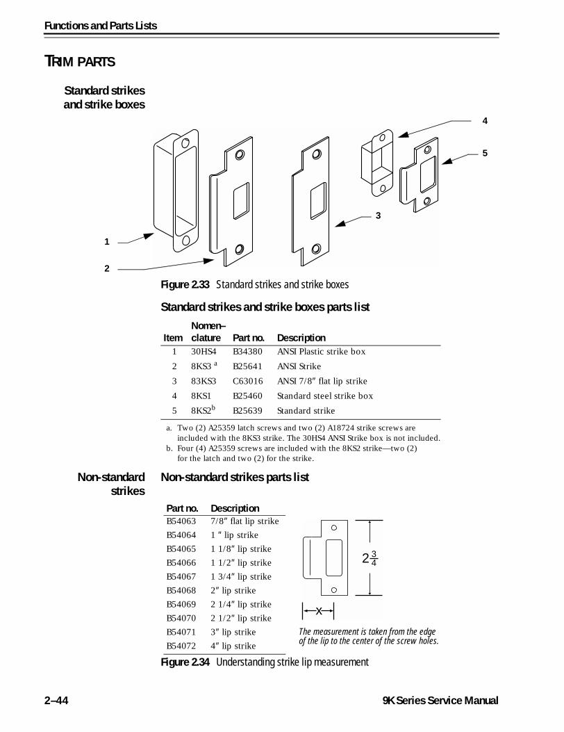
TRIM PARTS
Standard strikesand strike boxes
Standard strikes and strike boxes parts list
Non-standardstrikes
Non-standard strikes parts list
Figure 2.33 Standard strikes and strike boxes
1
2
4
5
3
ItemNomen–clature Part no. Description
1 30HS4 B34380 ANSI Plastic strike box
2 8KS3 a
a. Two (2) A25359 latch screws and two (2) A18724 strike screws are included with the 8KS3 strike. The 30HS4 ANSI Strike box is not included.
B25641 ANSI Strike
3 83KS3 C63016 ANSI 7/8″ flat lip strike
4 8KS1 B25460 Standard steel strike box
5 8KS2b
b. Four (4) A25359 screws are included with the 8KS2 strike—two (2) for the latch and two (2) for the strike.
B25639 Standard strike
Figure 2.34 Understanding strike lip measurement
x
2 34
The measurement is taken from the edge of the lip to the center of the screw holes.
Part no. DescriptionB54063 7/8″ flat lip strike
B54064 1 ″ lip strike
B54065 1 1/8″ lip strike
B54066 1 1/2″ lip strike
B54067 1 3/4″ lip strike
B54068 2″ lip strike
B54069 2 1/4″ lip strike
B54070 2 1/2″ lip strike
B54071 3″ lip strike
B54072 4″ lip strike
2–44 9K Series Service Manual
Functions and Parts Lists
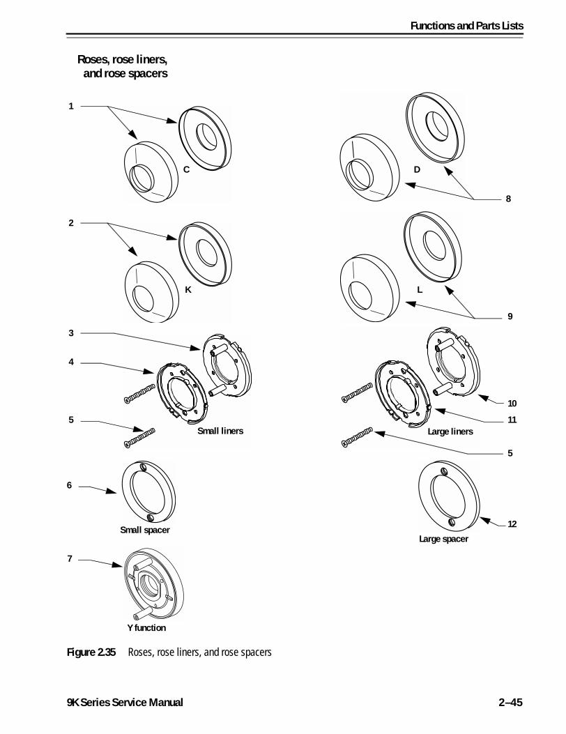
Roses, rose liners,and rose spacers
Figure 2.35 Roses, rose liners, and rose spacers
1
8
2
9
3
4
5
7
10
12
C D
K L
Small liners Large liners
Y function
Small spacerLarge spacer
6
11
5
9K Series Service Manual 2–45
Functions and Parts Lists
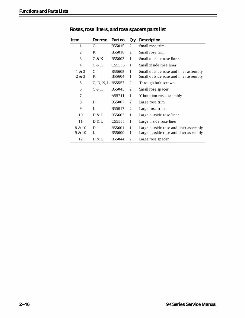
Roses, rose liners, and rose spacers parts list
Item For rose Part no. Qty. Description1 C B55015 2 Small rose trim
2 K B55018 2 Small rose trim
3 C & K B55603 1 Small outside rose liner
4 C & K C55556 1 Small inside rose liner
1 & 32 & 3
CK
B55605B55604
11
Small outside rose and liner assemblySmall outside rose and liner assembly
5 C, D, K, L B55557 2 Through-bolt screws
6 C & K B55043 2 Small rose spacer
7 A55711 1 Y function rose assembly
8 D B55007 2 Large rose trim
9 L B55017 2 Large rose trim
10 D & L B55602 1 Large outside rose liner
11 D & L C55555 1 Large inside rose liner
8 & 109 & 10
DL
B55601B55600
11
Large outside rose and liner assemblyLarge outside rose and liner assembly
12 D & L B55044 2 Large rose spacer
2–46 9K Series Service Manual
Functions and Parts Lists
Standard levers and components
Standard levers parts list
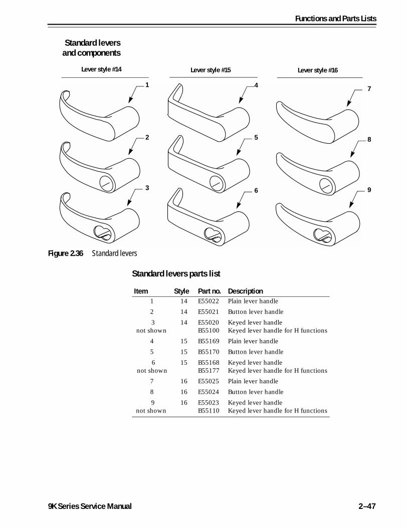
Figure 2.36 Standard levers
1
2
3
4
5
6
7
8
9
Lever style #14 Lever style #15 Lever style #16
Item Style Part no. Description1 14 E55022 Plain lever handle
2 14 E55021 Button lever handle
3not shown
14 E55020B55100
Keyed lever handleKeyed lever handle for H functions
4 15 B55169 Plain lever handle
5 15 B55170 Button lever handle
6not shown
15 B55168B55177
Keyed lever handleKeyed lever handle for H functions
7 16 E55025 Plain lever handle
8 16 E55024 Button lever handle
9not shown
16 E55023B55110
Keyed lever handleKeyed lever handle for H functions
9K Series Service Manual 2–47

Functions and Parts Lists
Standard lever components parts list
Figure 2.37 Standard lever components
1
2
3
4
5
Item Part no. Qty. Description1 B54210 1a
a. Single-keyed locks require one (1); double-keyed locks requiretwo (2).
Six pin throw memberb
b. For information about cores and keys, see the Core and Key Service Manual.
2 B54200 1a Seven pin throw memberb
3 A55697 1 “H” throw member
4 A55696 1 “HJ” throw member
5 B54182 1 Lever keeper spring
2–48 9K Series Service Manual
Functions and Parts Lists
Non-IC levers and components
Non-IC levers parts list
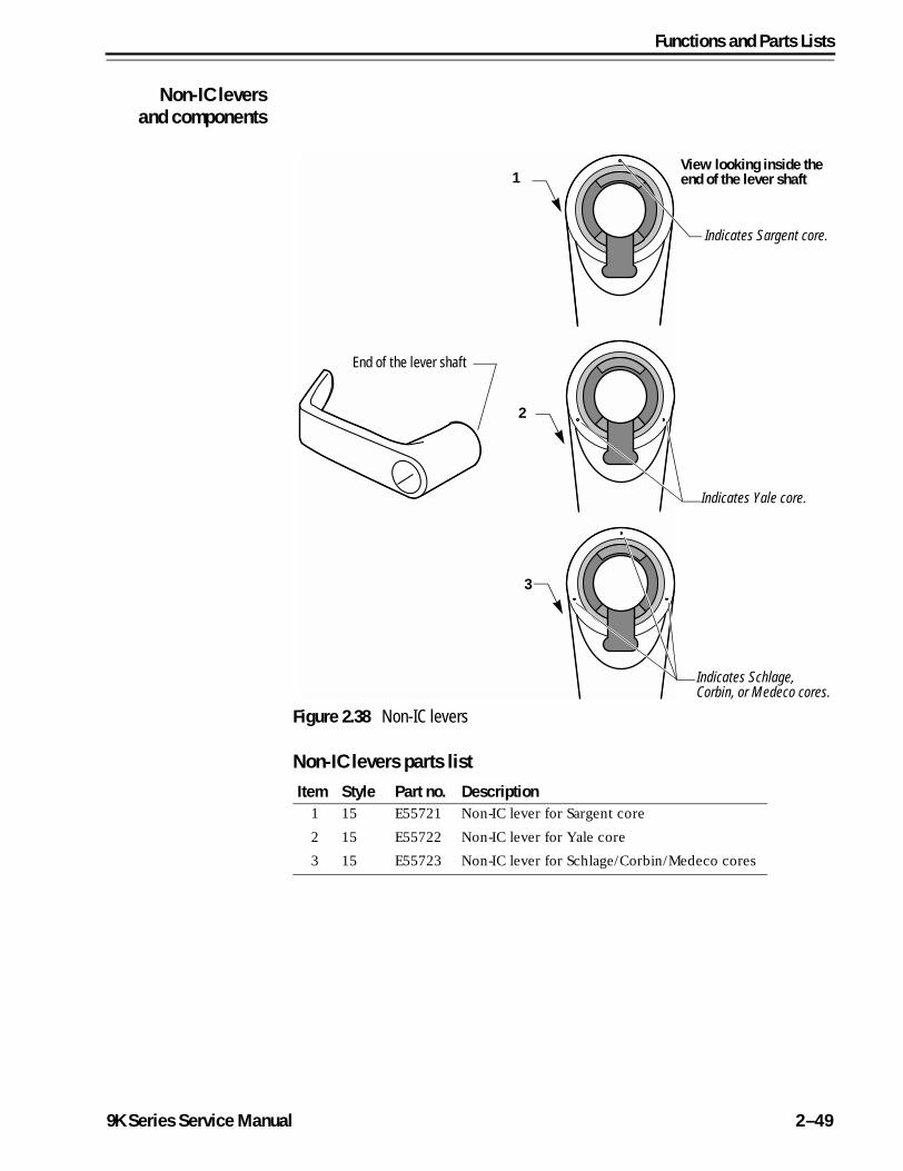
Figure 2.38 Non-IC levers
2
3
1View looking inside the end of the lever shaft
Indicates Sargent core.
End of the lever shaft
Indicates Yale core.
Indicates Schlage, Corbin, or Medeco cores.
Item Style Part no. Description1 15 E55721 Non-IC lever for Sargent core
2 15 E55722 Non-IC lever for Yale core
3 15 E55723 Non-IC lever for Schlage/Corbin/Medeco cores
9K Series Service Manual 2–49
Functions and Parts Lists
Non-IC lever components parts list
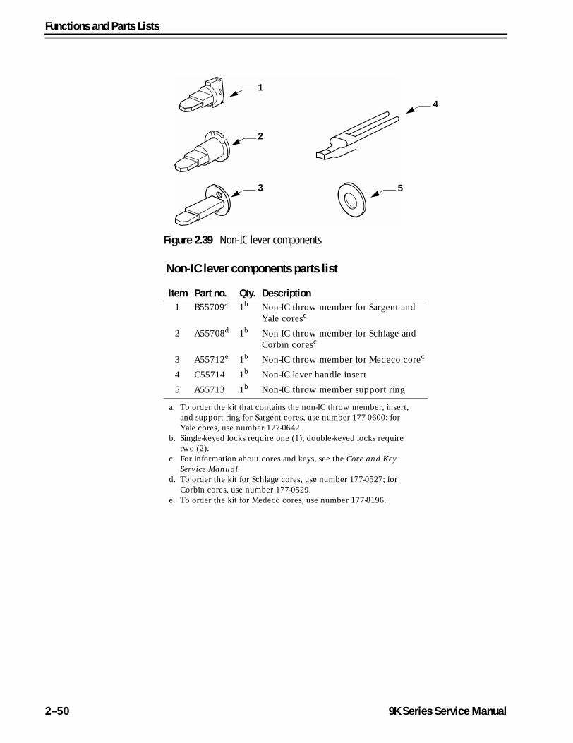
Figure 2.39 Non-IC lever components
1
2
3
4
5
Item Part no. Qty. Description1 B55709a
a. To order the kit that contains the non-IC throw member, insert, and support ring for Sargent cores, use number 177-0600; for Yale cores, use number 177-0642.
1b
b. Single-keyed locks require one (1); double-keyed locks requiretwo (2).
Non-IC throw member for Sargent and Yale coresc
c. For information about cores and keys, see the Core and Key Service Manual.
2 A55708d
d. To order the kit for Schlage cores, use number 177-0527; for Corbin cores, use number 177-0529.
1b Non-IC throw member for Schlage and Corbin coresc
3 A55712e
e. To order the kit for Medeco cores, use number 177-8196.
1b Non-IC throw member for Medeco corec
4 C55714 1b Non-IC lever handle insert
5 A55713 1b Non-IC throw member support ring
2–50 9K Series Service Manual
Functions and Parts Lists
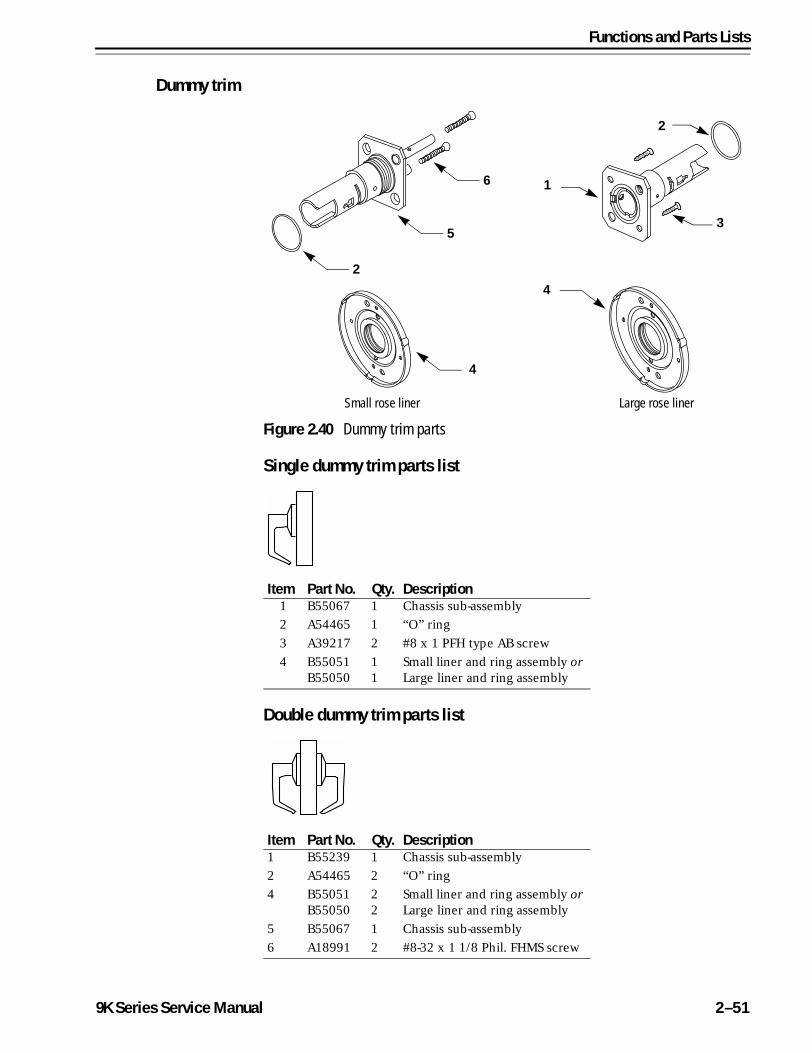
Dummy trim
Single dummy trim parts list
Double dummy trim parts list
Figure 2.40 Dummy trim parts
1
3
2
4
Large rose linerSmall rose liner
4
2
5
6
Item Part No. Qty. Description1 B55067 1 Chassis sub-assembly
2 A54465 1 “O” ring
3 A39217 2 #8 x 1 PFH type AB screw
4 B55051B55050
11
Small liner and ring assembly orLarge liner and ring assembly
Item Part No. Qty. Description1 B55239 1 Chassis sub-assembly
2 A54465 2 “O” ring
4 B55051B55050
22
Small liner and ring assembly orLarge liner and ring assembly
5 B55067 1 Chassis sub-assembly
6 A18991 2 #8-32 x 1 1/8 Phil. FHMS screw
9K Series Service Manual 2–51
Functions and Parts Lists
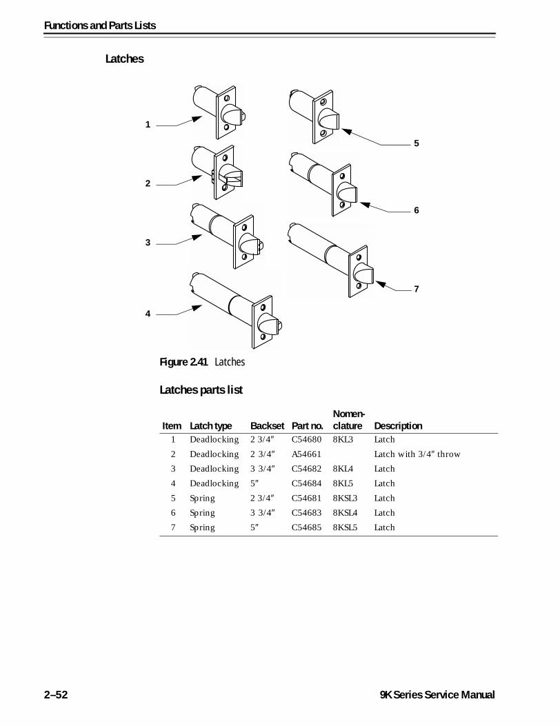
Latches
Latches parts list
Figure 2.41 Latches
1
2
3
4
5
6
7
Item Latch type Backset Part no.Nomen-clature Description
1 Deadlocking 2 3/4″ C54680 8KL3 Latch
2 Deadlocking 2 3/4″ A54661 Latch with 3/4″ throw
3 Deadlocking 3 3/4″ C54682 8KL4 Latch
4 Deadlocking 5″ C54684 8KL5 Latch
5 Spring 2 3/4″ C54681 8KSL3 Latch
6 Spring 3 3/4″ C54683 8KSL4 Latch
7 Spring 5″ C54685 8KSL5 Latch
2–52 9K Series Service Manual
Functions and Parts Lists
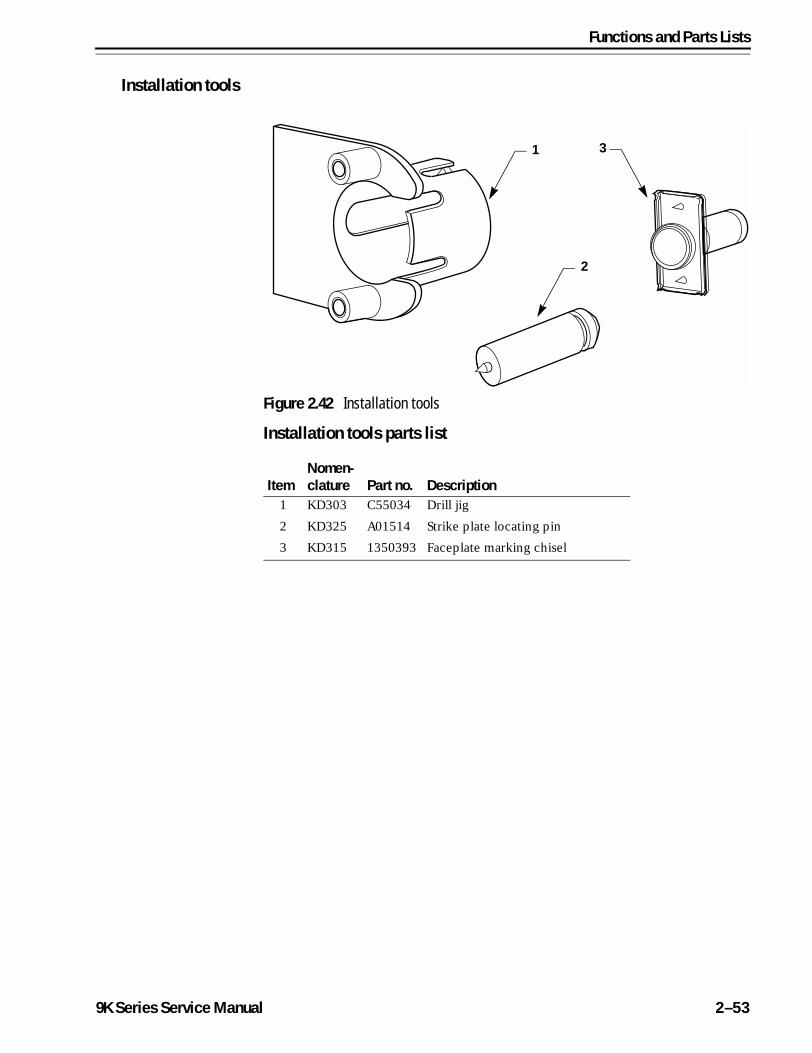
Installation tools
Installation tools parts list
Figure 2.42 Installation tools
1
2
3
ItemNomen-clature Part no. Description
1 KD303 C55034 Drill jig
2 KD325 A01514 Strike plate locating pin
3 KD315 1350393 Faceplate marking chisel
9K Series Service Manual 2–53
Functions and Parts Lists
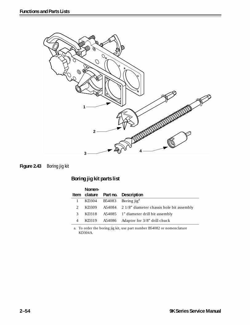
Boring jig kit parts list
Figure 2.43 Boring jig kit
1
2
3 4
ItemNomen-clature Part no. Description
1 KD304 B54083 Boring jiga
a. To order the boring jig kit, use part number B54082 or nomenclature KD304A.
2 KD309 A54084 2 1/8″ diameter chassis hole bit assembly
3 KD318 A54085 1″ diameter drill bit assembly
4 KD319 A54086 Adaptor for 3/8″ drill chuck
2–54 9K Series Service Manual
3
9K Series Service
SERVICE AND MAINTENANCE
This chapter contains instructions for removing and replacing components, servicing and maintaining components, and troubleshooting common questions.
ToSee page
Replace levers 3–3
Replace roses 3–4
Replace button assemblies 3–7
Replace the lever keeper spring 3–9
Replace the lever return spring 3–10
Replace the key release cam assembly 3–14
Replace the spring drive plate 3–15
Replace the sleeve assembly 3–16
Lubricate cores 3–18
Align chassis and trim 3–19
Position the locking cam for C function locks 3–20
Position the locking cam for G and IN function locks 3–21
Use the emergency key for H and HJ function locks 3–22
Troubleshoot common questions 3–23
Manual 3–1
Service and Maintenance
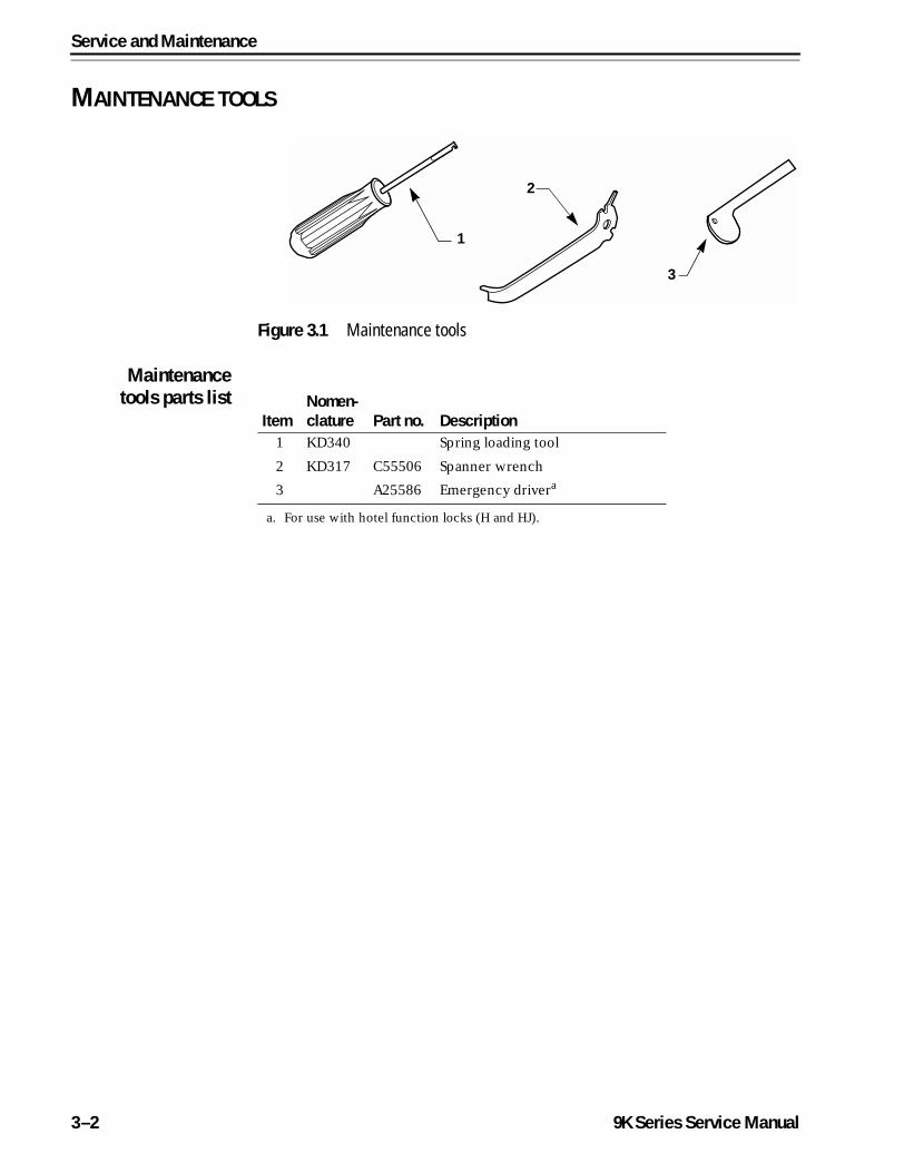
MAINTENANCE TOOLS
Maintenancetools parts list
Figure 3.1 Maintenance tools
2
3
1
ItemNomen-clature Part no. Description
1 KD340 Spring loading tool
2 KD317 C55506 Spanner wrench
3 A25586 Emergency drivera
a. For use with hotel function locks (H and HJ).
3–2 9K Series Service Manual
Service and Maintenance
REPLACING PARTS
Replacing thelever
To remove the keyed lever:1. Insert the control key into the core and rotate the key 15 degrees to
the right.
2. Remove the core and throw member from the lever.
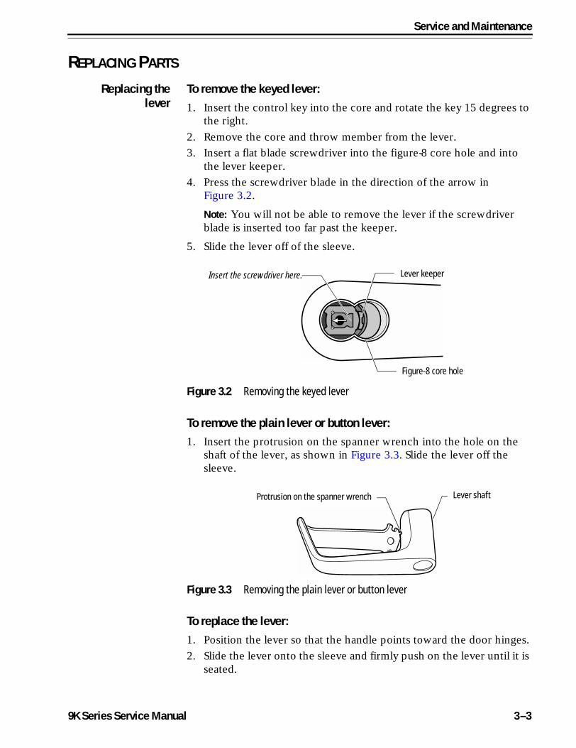
3. Insert a flat blade screwdriver into the figure-8 core hole and into the lever keeper.
4. Press the screwdriver blade in the direction of the arrow in Figure 3.2.
Note: You will not be able to remove the lever if the screwdriver blade is inserted too far past the keeper.
5. Slide the lever off of the sleeve.
To remove the plain lever or button lever:1. Insert the protrusion on the spanner wrench into the hole on the
shaft of the lever, as shown in Figure 3.3. Slide the lever off the sleeve.
To replace the lever:1. Position the lever so that the handle points toward the door hinges.
2. Slide the lever onto the sleeve and firmly push on the lever until it is seated.
Figure 3.2 Removing the keyed lever
Insert the screwdriver here.
Figure-8 core hole
Lever keeper
Figure 3.3 Removing the plain lever or button lever
Protrusion on the spanner wrench Lever shaft
9K Series Service Manual 3–3
Service and Maintenance
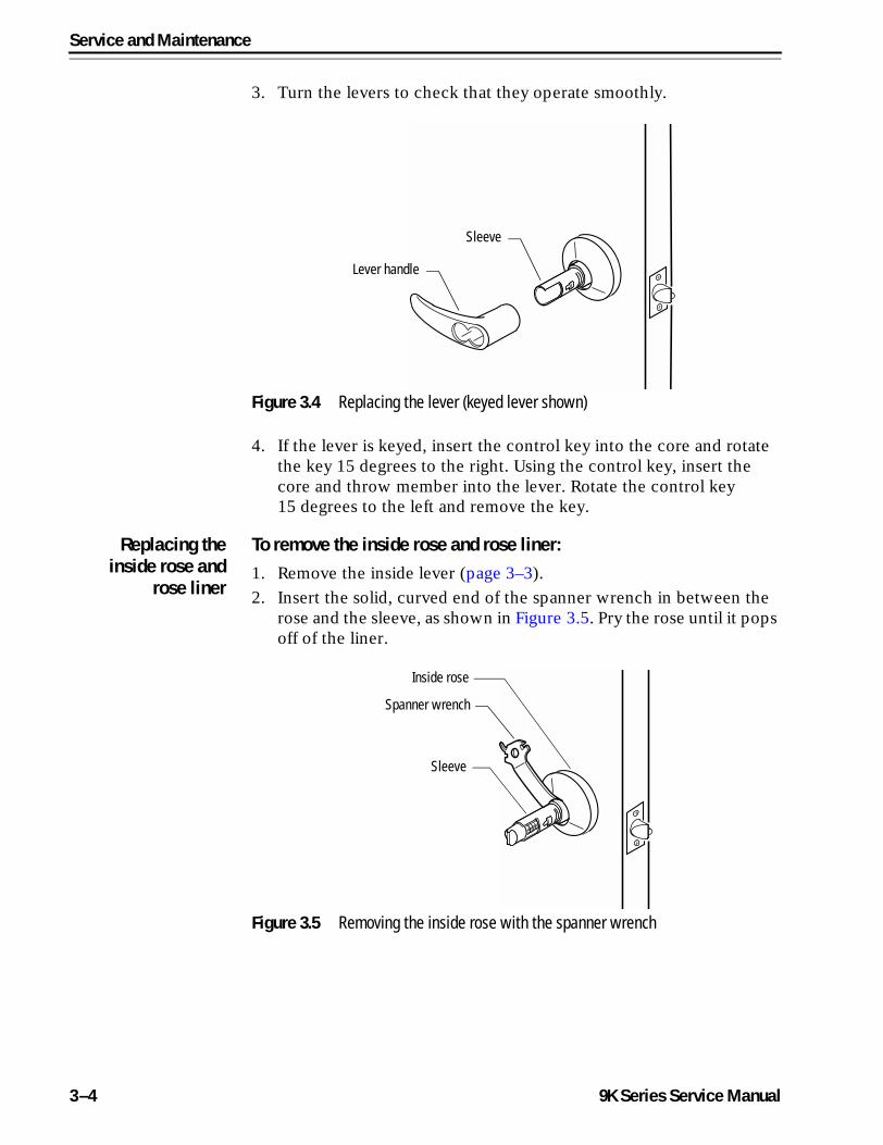
3. Turn the levers to check that they operate smoothly.
4. If the lever is keyed, insert the control key into the core and rotate the key 15 degrees to the right. Using the control key, insert the core and throw member into the lever. Rotate the control key 15 degrees to the left and remove the key.
Replacing theinside rose and
rose liner
To remove the inside rose and rose liner:1. Remove the inside lever (page 3–3).
2. Insert the solid, curved end of the spanner wrench in between the rose and the sleeve, as shown in Figure 3.5. Pry the rose until it pops off of the liner.
Figure 3.4 Replacing the lever (keyed lever shown)
Sleeve
Lever handle
Figure 3.5 Removing the inside rose with the spanner wrench
Spanner wrench
Inside rose
Sleeve
3–4 9K Series Service Manual
Service and Maintenance
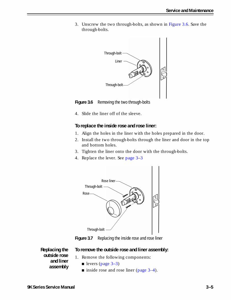
3. Unscrew the two through-bolts, as shown in Figure 3.6. Save the through-bolts.
4. Slide the liner off of the sleeve.
To replace the inside rose and rose liner:1. Align the holes in the liner with the holes prepared in the door.
2. Install the two through-bolts through the liner and door in the top and bottom holes.
3. Tighten the liner onto the door with the through-bolts.
4. Replace the lever. See page 3–3
Replacing theoutside rose
and linerassembly
To remove the outside rose and liner assembly:1. Remove the following components:
■ levers (page 3–3)
■ inside rose and rose liner (page 3–4).
Figure 3.6 Removing the two through-bolts
Through-bolt
Through-bolt
Liner
Figure 3.7 Replacing the inside rose and rose liner
Through-bolt
Through-bolt
Rose liner
Rose
9K Series Service Manual 3–5
Service and Maintenance
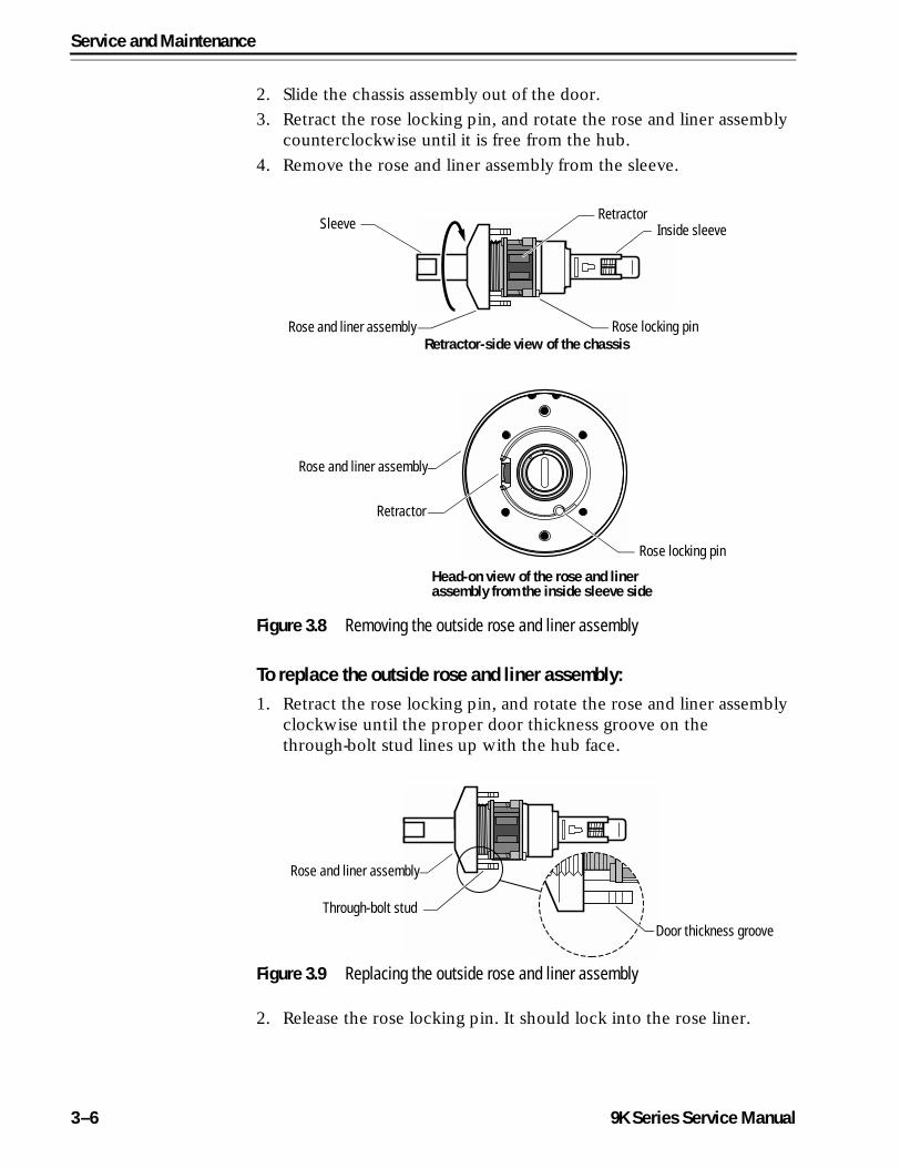
2. Slide the chassis assembly out of the door.
3. Retract the rose locking pin, and rotate the rose and liner assembly counterclockwise until it is free from the hub.
4. Remove the rose and liner assembly from the sleeve.
To replace the outside rose and liner assembly:1. Retract the rose locking pin, and rotate the rose and liner assembly
clockwise until the proper door thickness groove on the through-bolt stud lines up with the hub face.
2. Release the rose locking pin. It should lock into the rose liner.
Figure 3.8 Removing the outside rose and liner assembly
Sleeve
Rose and liner assembly Rose locking pinRetractor-side view of the chassis
RetractorInside sleeve
Head-on view of the rose and liner assembly from the inside sleeve side
Rose locking pin
Retractor
Rose and liner assembly
Figure 3.9 Replacing the outside rose and liner assembly
Rose and liner assembly
Through-bolt stud
Door thickness groove
3–6 9K Series Service Manual
Service and Maintenance
3. Install the lock chassis assembly from the outside. Make sure the latch tabs engage the chassis frame and the latch tailpiece engages the retractor.
4. Replace the following components:
■ inside rose and rose liner (page 3–5)
■ levers (page 3–3).
Replacing thebutton
assembly
To remove the button assembly:
Note: These instructions apply for all types of button assemblies.
1. Remove the following components:
■ levers (page 3–3)
■ roses and rose liners (page 3–4 or page 3–5).
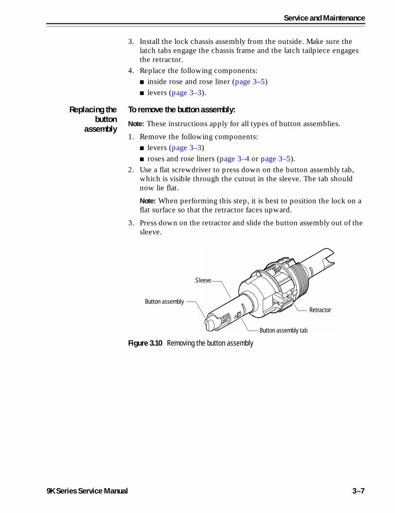
2. Use a flat screwdriver to press down on the button assembly tab, which is visible through the cutout in the sleeve. The tab should now lie flat.
Note: When performing this step, it is best to position the lock on a flat surface so that the retractor faces upward.
3. Press down on the retractor and slide the button assembly out of the sleeve.
Figure 3.10 Removing the button assembly
Button assembly tab
Sleeve
RetractorButton assembly
9K Series Service Manual 3–7
Service and Maintenance
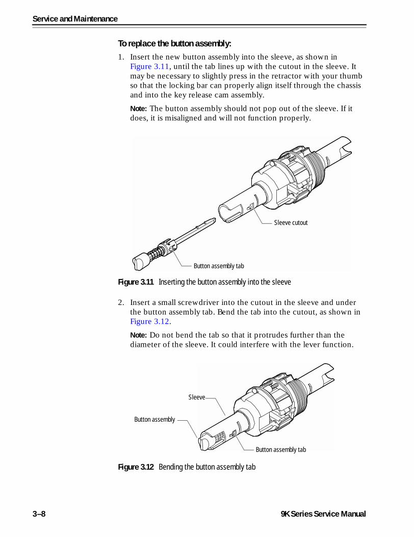
To replace the button assembly:1. Insert the new button assembly into the sleeve, as shown in
Figure 3.11, until the tab lines up with the cutout in the sleeve. It may be necessary to slightly press in the retractor with your thumb so that the locking bar can properly align itself through the chassis and into the key release cam assembly.
Note: The button assembly should not pop out of the sleeve. If it does, it is misaligned and will not function properly.
2. Insert a small screwdriver into the cutout in the sleeve and under the button assembly tab. Bend the tab into the cutout, as shown in Figure 3.12.
Note: Do not bend the tab so that it protrudes further than the diameter of the sleeve. It could interfere with the lever function.
Figure 3.11 Inserting the button assembly into the sleeve
Button assembly tab
Sleeve cutout
Figure 3.12 Bending the button assembly tab
Button assembly tab
Sleeve
Button assembly
3–8 9K Series Service Manual
Service and Maintenance
3. Replace the following components:
■ roses and rose liners (page 3–4 or page 3–5)
■ levers (page 3–3).
Replacing thelever keeper
spring
To remove the lever keeper spring:1. Remove the following components:
■ levers (page 3–3)
■ roses and rose liners (page 3–4 and page 3–5)
■ button assembly, if present (page 3–7).
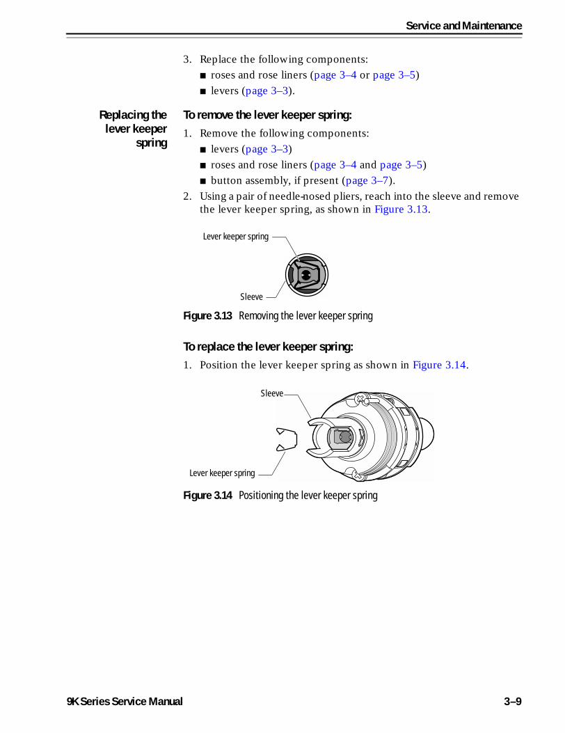
2. Using a pair of needle-nosed pliers, reach into the sleeve and remove the lever keeper spring, as shown in Figure 3.13.
To replace the lever keeper spring:1. Position the lever keeper spring as shown in Figure 3.14.
Figure 3.13 Removing the lever keeper spring
Lever keeper spring
Sleeve
Figure 3.14 Positioning the lever keeper spring
Lever keeper spring
Sleeve
9K Series Service Manual 3–9
Service and Maintenance
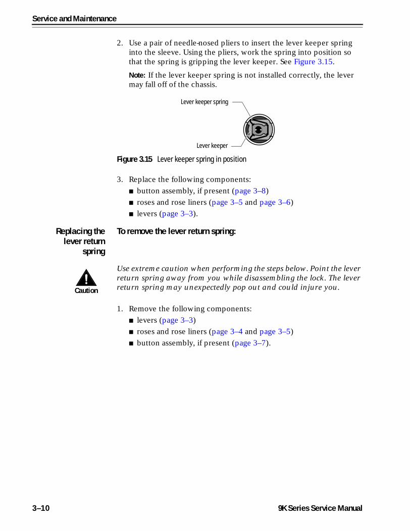
2. Use a pair of needle-nosed pliers to insert the lever keeper spring into the sleeve. Using the pliers, work the spring into position so that the spring is gripping the lever keeper. See Figure 3.15.
Note: If the lever keeper spring is not installed correctly, the lever may fall off of the chassis.
3. Replace the following components:
■ button assembly, if present (page 3–8)
■ roses and rose liners (page 3–5 and page 3–6)
■ levers (page 3–3).
Replacing thelever return
spring
To remove the lever return spring:
Caution
Use extreme caution when performing the steps below. Point the lever return spring away from you while disassembling the lock. The lever return spring may unexpectedly pop out and could injure you.
1. Remove the following components:
■ levers (page 3–3)
■ roses and rose liners (page 3–4 and page 3–5)
■ button assembly, if present (page 3–7).
Figure 3.15 Lever keeper spring in position
Lever keeper spring
Lever keeper
3–10 9K Series Service Manual
Service and Maintenance
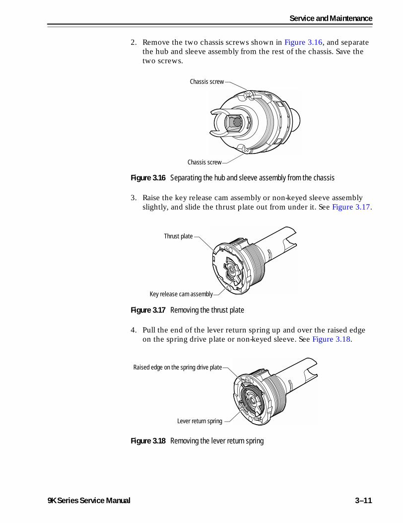
2. Remove the two chassis screws shown in Figure 3.16, and separate the hub and sleeve assembly from the rest of the chassis. Save the two screws.
3. Raise the key release cam assembly or non-keyed sleeve assembly slightly, and slide the thrust plate out from under it. See Figure 3.17.
4. Pull the end of the lever return spring up and over the raised edge on the spring drive plate or non-keyed sleeve. See Figure 3.18.
Figure 3.16 Separating the hub and sleeve assembly from the chassis
Chassis screw
Chassis screw
Figure 3.17 Removing the thrust plate
Thrust plate
Key release cam assembly
Figure 3.18 Removing the lever return spring
Lever return spring
Raised edge on the spring drive plate
9K Series Service Manual 3–11
Service and Maintenance
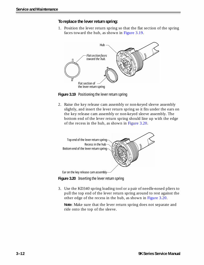
To replace the lever return spring:1. Position the lever return spring so that the flat section of the spring
faces toward the hub, as shown in Figure 3.19.
2. Raise the key release cam assembly or non-keyed sleeve assembly slightly, and insert the lever return spring so it fits under the ears on the key release cam assembly or non-keyed sleeve assembly. The bottom end of the lever return spring should line up with the edge of the recess in the hub, as shown in Figure 3.20.
3. Use the KD340 spring loading tool or a pair of needle-nosed pliers to pull the top end of the lever return spring around to rest against the other edge of the recess in the hub, as shown in Figure 3.20.
Note: Make sure that the lever return spring does not separate and ride onto the top of the sleeve.
Figure 3.19 Positioning the lever return spring
Hub
Flat section of the lever return spring
Flat section faces toward the hub.
Figure 3.20 Inserting the lever return spring
Bottom end of the lever return spring
Ear on the key release cam assembly
Top end of the lever return springRecess in the hub
3–12 9K Series Service Manual
Service and Maintenance
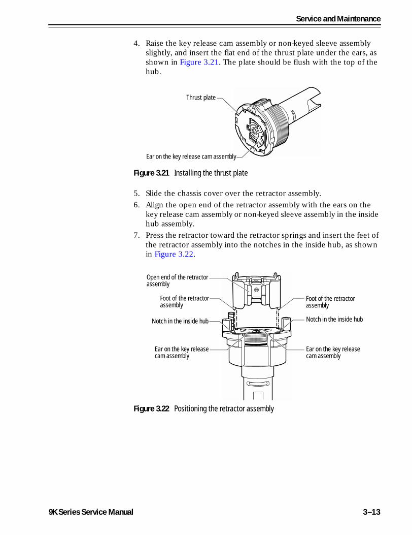
4. Raise the key release cam assembly or non-keyed sleeve assembly slightly, and insert the flat end of the thrust plate under the ears, as shown in Figure 3.21. The plate should be flush with the top of the hub.
5. Slide the chassis cover over the retractor assembly.
6. Align the open end of the retractor assembly with the ears on the key release cam assembly or non-keyed sleeve assembly in the inside hub assembly.
7. Press the retractor toward the retractor springs and insert the feet of the retractor assembly into the notches in the inside hub, as shown in Figure 3.22.
Figure 3.21 Installing the thrust plate
Thrust plate
Ear on the key release cam assembly
Figure 3.22 Positioning the retractor assembly
Foot of the retractorassembly
Notch in the inside hub
Open end of the retractorassembly
Foot of the retractor assembly
Notch in the inside hub
Ear on the key release cam assembly
Ear on the key release cam assembly
9K Series Service Manual 3–13
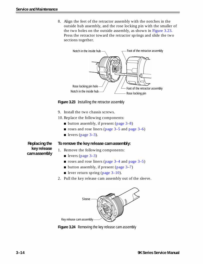
Service and Maintenance
8. Align the feet of the retractor assembly with the notches in the outside hub assembly, and the rose locking pin with the smaller of the two holes on the outside assembly, as shown in Figure 3.23. Press the retractor toward the retractor springs and slide the two sections together.
9. Install the two chassis screws.
10. Replace the following components:
■ button assembly, if present (page 3–8)
■ roses and rose liners (page 3–5 and page 3–6)
■ levers (page 3–3).
Replacing thekey release
cam assembly
To remove the key release cam assembly:1. Remove the following components:
■ levers (page 3–3)
■ roses and rose liners (page 3–4 and page 3–5)
■ button assembly, if present (page 3–7)
■ lever return spring (page 3–10).
2. Pull the key release cam assembly out of the sleeve.
Figure 3.23 Installing the retractor assembly
Rose locking pinFoot of the retractor assembly
Rose locking pin hole
Notch in the inside hub
Foot of the retractor assemblyNotch in the inside hub
Figure 3.24 Removing the key release cam assembly
Key release cam assembly
Sleeve
3–14 9K Series Service Manual
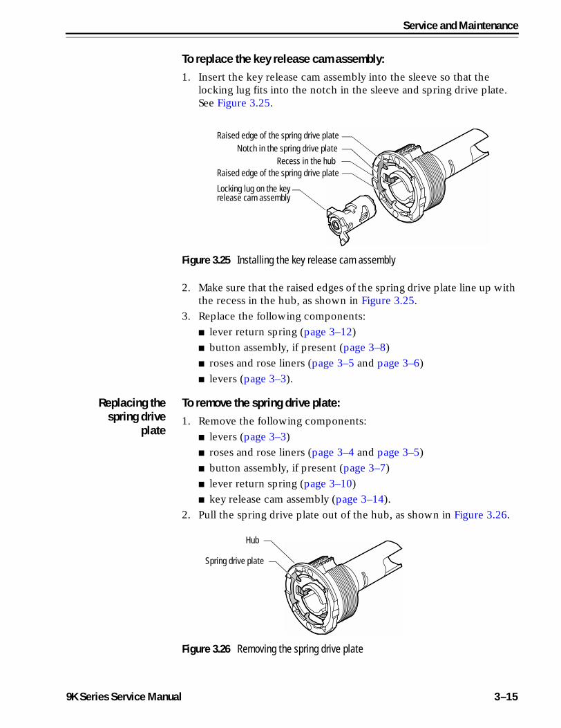
Service and Maintenance
To replace the key release cam assembly:1. Insert the key release cam assembly into the sleeve so that the
locking lug fits into the notch in the sleeve and spring drive plate. See Figure 3.25.
2. Make sure that the raised edges of the spring drive plate line up with the recess in the hub, as shown in Figure 3.25.
3. Replace the following components:
■ lever return spring (page 3–12)
■ button assembly, if present (page 3–8)
■ roses and rose liners (page 3–5 and page 3–6)
■ levers (page 3–3).
Replacing thespring drive
plate
To remove the spring drive plate:1. Remove the following components:
■ levers (page 3–3)
■ roses and rose liners (page 3–4 and page 3–5)
■ button assembly, if present (page 3–7)
■ lever return spring (page 3–10)
■ key release cam assembly (page 3–14).
2. Pull the spring drive plate out of the hub, as shown in Figure 3.26.
Figure 3.25 Installing the key release cam assembly
Locking lug on the key release cam assembly
Notch in the spring drive plateRaised edge of the spring drive plate
Raised edge of the spring drive plateRecess in the hub
Figure 3.26 Removing the spring drive plate
Spring drive plate
Hub
9K Series Service Manual 3–15
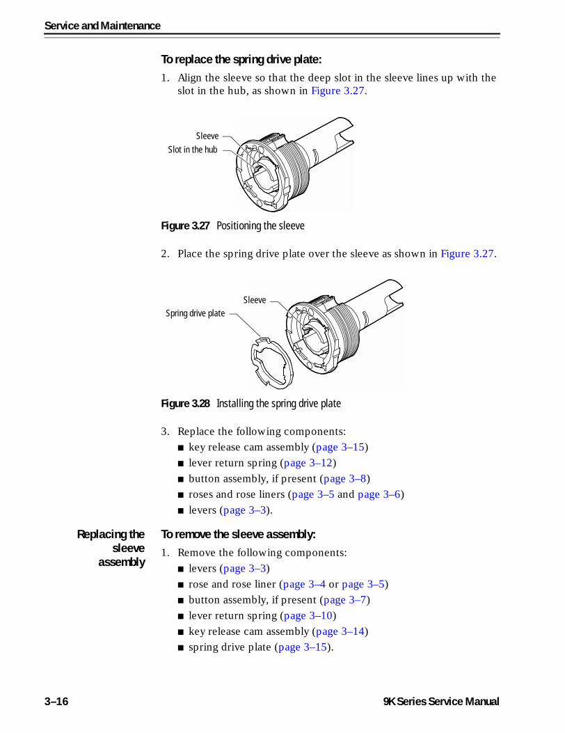
Service and Maintenance
To replace the spring drive plate:1. Align the sleeve so that the deep slot in the sleeve lines up with the
slot in the hub, as shown in Figure 3.27.
2. Place the spring drive plate over the sleeve as shown in Figure 3.27.
3. Replace the following components:
■ key release cam assembly (page 3–15)
■ lever return spring (page 3–12)
■ button assembly, if present (page 3–8)
■ roses and rose liners (page 3–5 and page 3–6)
■ levers (page 3–3).
Replacing thesleeve
assembly
To remove the sleeve assembly:1. Remove the following components:
■ levers (page 3–3)
■ rose and rose liner (page 3–4 or page 3–5)
■ button assembly, if present (page 3–7)
■ lever return spring (page 3–10)
■ key release cam assembly (page 3–14)
■ spring drive plate (page 3–15).
Figure 3.27 Positioning the sleeve
Slot in the hubSleeve
Figure 3.28 Installing the spring drive plate
Spring drive plateSleeve
3–16 9K Series Service Manual
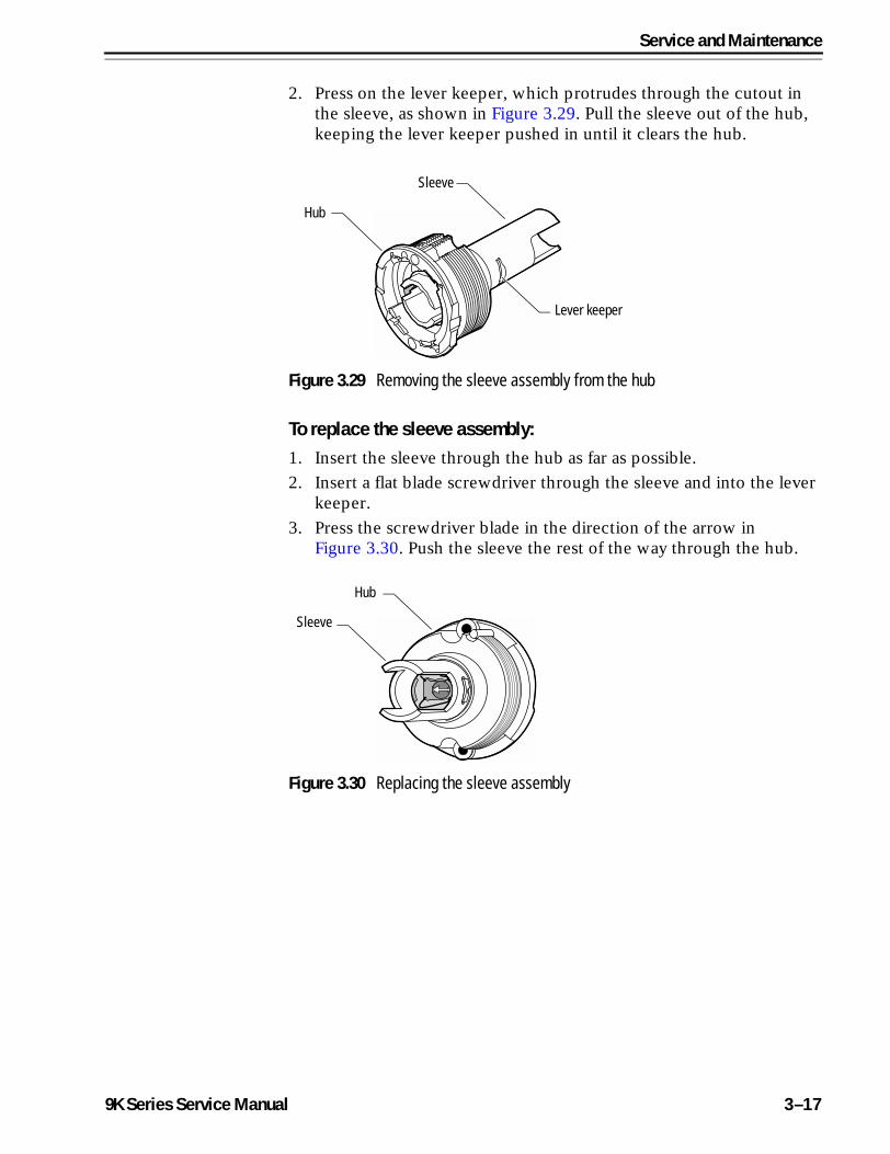
Service and Maintenance
2. Press on the lever keeper, which protrudes through the cutout in the sleeve, as shown in Figure 3.29. Pull the sleeve out of the hub, keeping the lever keeper pushed in until it clears the hub.
To replace the sleeve assembly:1. Insert the sleeve through the hub as far as possible.
2. Insert a flat blade screwdriver through the sleeve and into the lever keeper.
3. Press the screwdriver blade in the direction of the arrow in Figure 3.30. Push the sleeve the rest of the way through the hub.
Figure 3.29 Removing the sleeve assembly from the hub
Lever keeper
Sleeve
Hub
Figure 3.30 Replacing the sleeve assembly
Sleeve
Hub
9K Series Service Manual 3–17
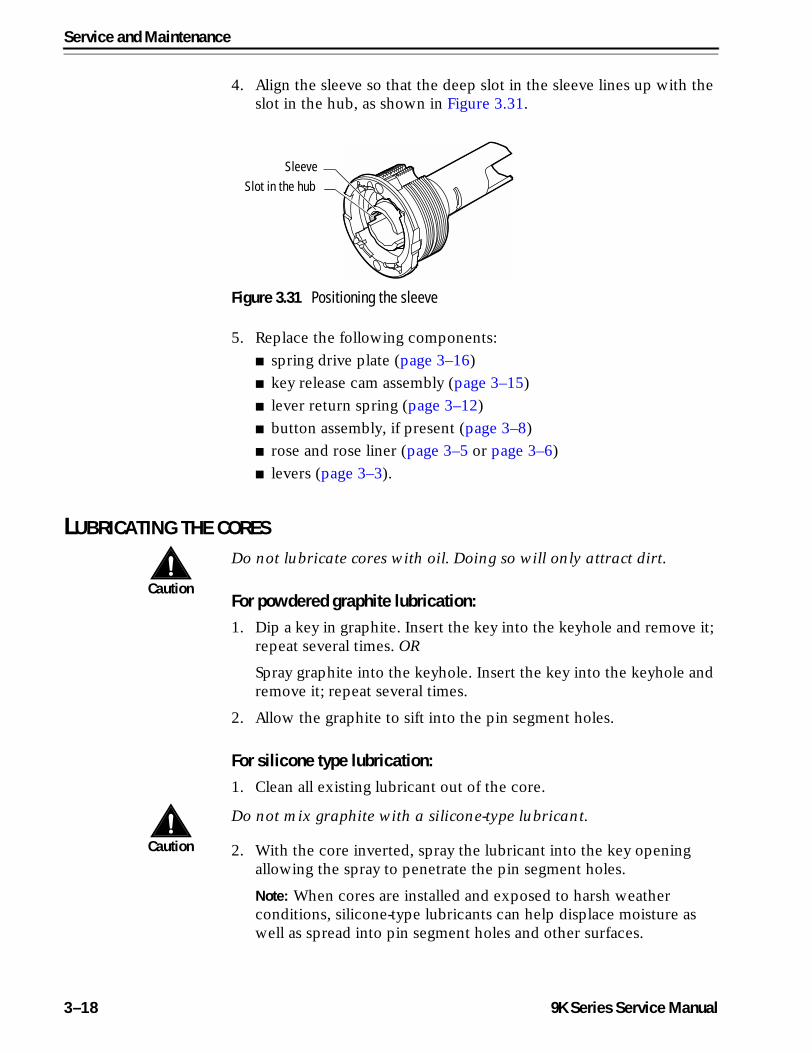
Service and Maintenance
4. Align the sleeve so that the deep slot in the sleeve lines up with the slot in the hub, as shown in Figure 3.31.
5. Replace the following components:
■ spring drive plate (page 3–16)
■ key release cam assembly (page 3–15)
■ lever return spring (page 3–12)
■ button assembly, if present (page 3–8)
■ rose and rose liner (page 3–5 or page 3–6)
■ levers (page 3–3).
LUBRICATING THE CORES
Caution
Do not lubricate cores with oil. Doing so will only attract dirt.
For powdered graphite lubrication:1. Dip a key in graphite. Insert the key into the keyhole and remove it;
repeat several times. OR
Spray graphite into the keyhole. Insert the key into the keyhole and remove it; repeat several times.
2. Allow the graphite to sift into the pin segment holes.
For silicone type lubrication:1. Clean all existing lubricant out of the core.
Caution
Do not mix graphite with a silicone-type lubricant.
2. With the core inverted, spray the lubricant into the key opening allowing the spray to penetrate the pin segment holes.
Note: When cores are installed and exposed to harsh weather conditions, silicone-type lubricants can help displace moisture as well as spread into pin segment holes and other surfaces.
Figure 3.31 Positioning the sleeve
Slot in the hubSleeve
3–18 9K Series Service Manual
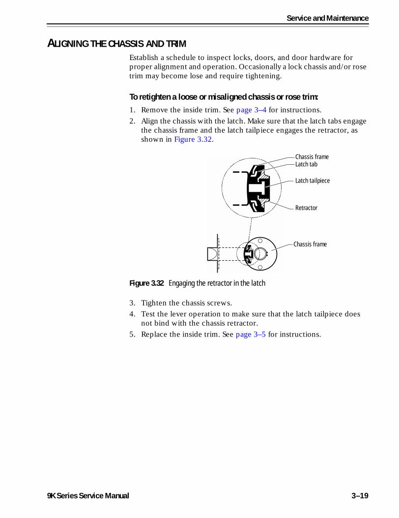
Service and Maintenance
ALIGNING THE CHASSIS AND TRIMEstablish a schedule to inspect locks, doors, and door hardware for proper alignment and operation. Occasionally a lock chassis and/or rose trim may become lose and require tightening.
To retighten a loose or misaligned chassis or rose trim:1. Remove the inside trim. See page 3–4 for instructions.
2. Align the chassis with the latch. Make sure that the latch tabs engage the chassis frame and the latch tailpiece engages the retractor, as shown in Figure 3.32.
3. Tighten the chassis screws.
4. Test the lever operation to make sure that the latch tailpiece does not bind with the chassis retractor.
5. Replace the inside trim. See page 3–5 for instructions.
Figure 3.32 Engaging the retractor in the latch
Chassis frameLatch tab
Latch tailpiece
Retractor
Chassis frame
9K Series Service Manual 3–19
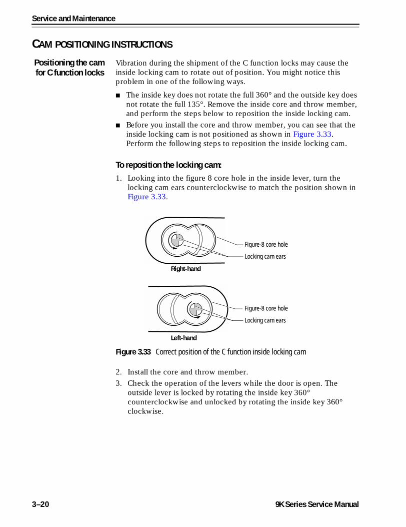
Service and Maintenance
CAM POSITIONING INSTRUCTIONS
Positioning the camfor C function locks
Vibration during the shipment of the C function locks may cause the inside locking cam to rotate out of position. You might notice this problem in one of the following ways.
■ The inside key does not rotate the full 360° and the outside key does not rotate the full 135°. Remove the inside core and throw member, and perform the steps below to reposition the inside locking cam.
■ Before you install the core and throw member, you can see that the inside locking cam is not positioned as shown in Figure 3.33. Perform the following steps to reposition the inside locking cam.
To reposition the locking cam:1. Looking into the figure 8 core hole in the inside lever, turn the
locking cam ears counterclockwise to match the position shown in Figure 3.33.
2. Install the core and throw member.
3. Check the operation of the levers while the door is open. The outside lever is locked by rotating the inside key 360° counterclockwise and unlocked by rotating the inside key 360° clockwise.
Figure 3.33 Correct position of the C function inside locking cam
Right-hand
Left-hand
Figure-8 core hole
Locking cam ears
Figure-8 core hole
Locking cam ears
3–20 9K Series Service Manual
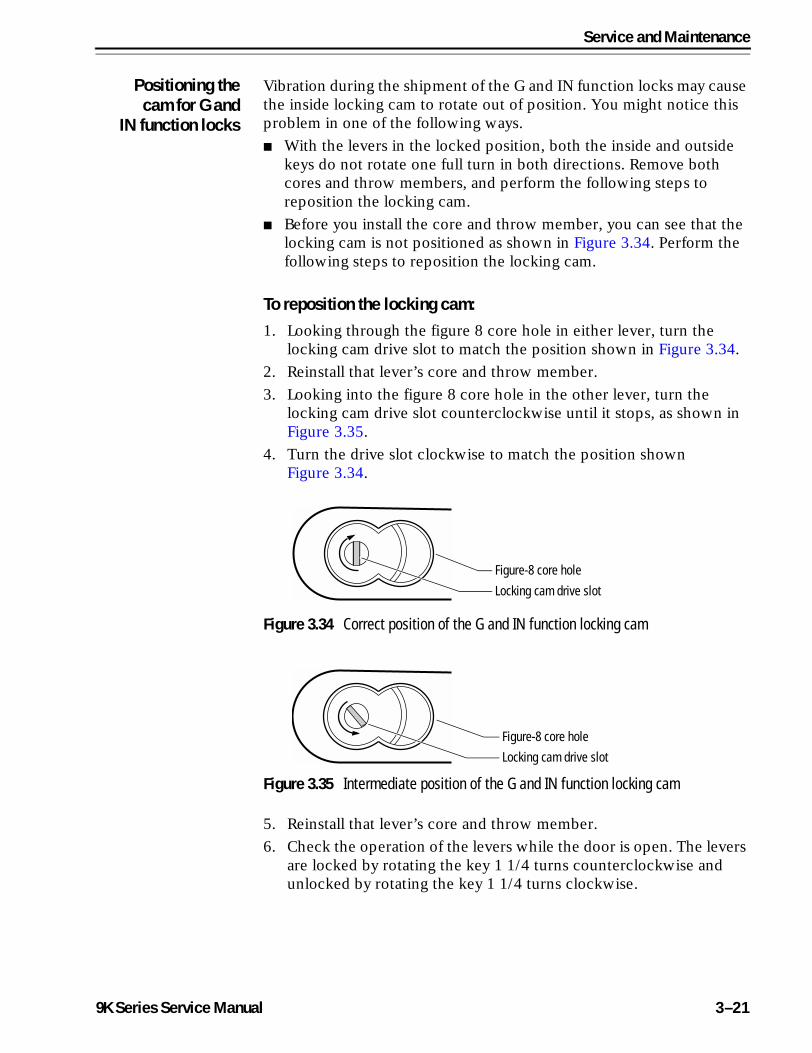
Service and Maintenance
Positioning thecam for G and
IN function locks
Vibration during the shipment of the G and IN function locks may cause the inside locking cam to rotate out of position. You might notice this problem in one of the following ways.
■ With the levers in the locked position, both the inside and outside keys do not rotate one full turn in both directions. Remove both cores and throw members, and perform the following steps to reposition the locking cam.
■ Before you install the core and throw member, you can see that the locking cam is not positioned as shown in Figure 3.34. Perform the following steps to reposition the locking cam.
To reposition the locking cam:1. Looking through the figure 8 core hole in either lever, turn the
locking cam drive slot to match the position shown in Figure 3.34.
2. Reinstall that lever’s core and throw member.
3. Looking into the figure 8 core hole in the other lever, turn the locking cam drive slot counterclockwise until it stops, as shown in Figure 3.35.
4. Turn the drive slot clockwise to match the position shown Figure 3.34.
5. Reinstall that lever’s core and throw member.
6. Check the operation of the levers while the door is open. The levers are locked by rotating the key 1 1/4 turns counterclockwise and unlocked by rotating the key 1 1/4 turns clockwise.
Figure 3.34 Correct position of the G and IN function locking cam
Figure 3.35 Intermediate position of the G and IN function locking cam
Figure-8 core hole
Locking cam drive slot
Figure-8 core hole
Locking cam drive slot
9K Series Service Manual 3–21
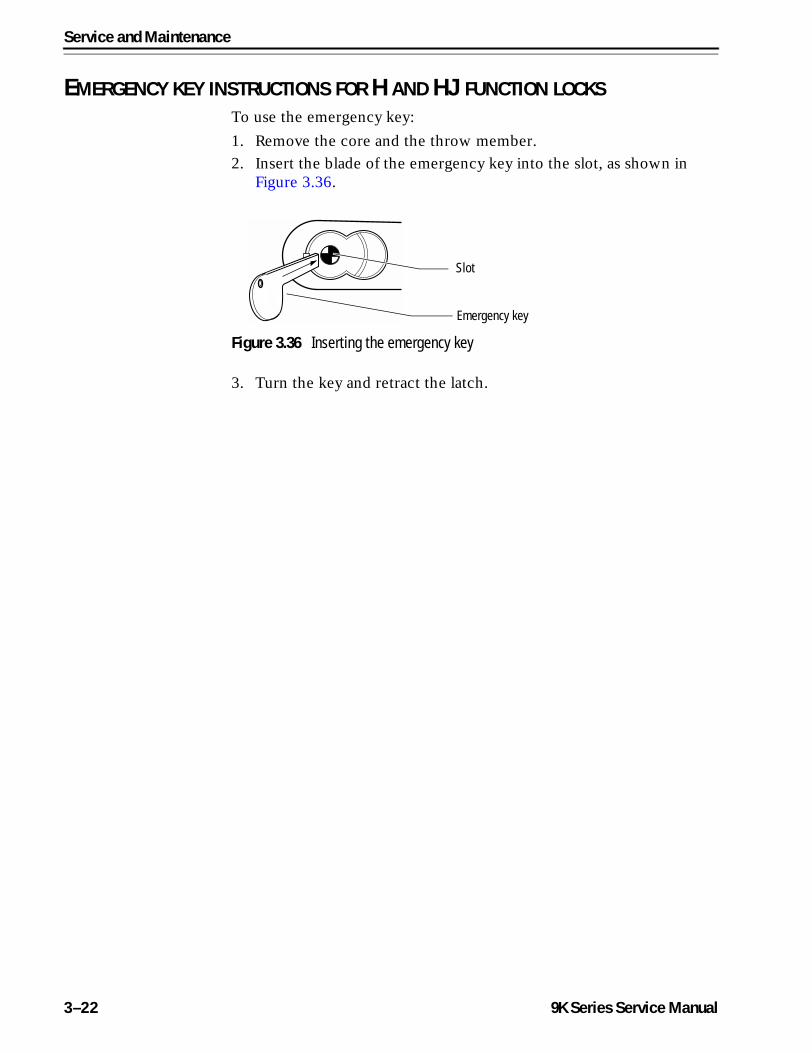
Service and Maintenance
EMERGENCY KEY INSTRUCTIONS FOR H AND HJ FUNCTION LOCKSTo use the emergency key:
1. Remove the core and the throw member.
2. Insert the blade of the emergency key into the slot, as shown in Figure 3.36.
3. Turn the key and retract the latch.
Figure 3.36 Inserting the emergency key
Slot
Emergency key
3–22 9K Series Service Manual
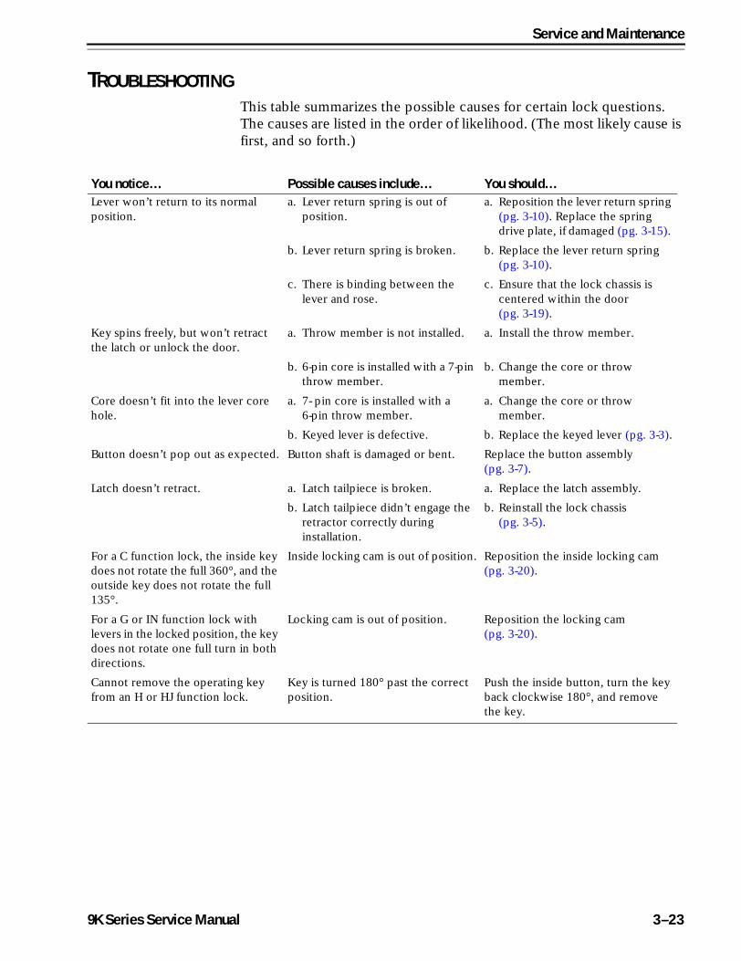
Service and Maintenance
TROUBLESHOOTINGThis table summarizes the possible causes for certain lock questions. The causes are listed in the order of likelihood. (The most likely cause is first, and so forth.)
You notice… Possible causes include… You should…Lever won’t return to its normal position.
a. Lever return spring is out of position.
a. Reposition the lever return spring (pg. 3-10). Replace the spring drive plate, if damaged (pg. 3-15).
b. Lever return spring is broken. b. Replace the lever return spring (pg. 3-10).
c. There is binding between the lever and rose.
c. Ensure that the lock chassis is centered within the door (pg. 3-19).
Key spins freely, but won’t retract the latch or unlock the door.
a. Throw member is not installed. a. Install the throw member.
b. 6-pin core is installed with a 7-pin throw member.
b. Change the core or throw member.
Core doesn’t fit into the lever core hole.
a. 7- pin core is installed with a 6-pin throw member.
a. Change the core or throw member.
b. Keyed lever is defective. b. Replace the keyed lever (pg. 3-3).
Button doesn’t pop out as expected. Button shaft is damaged or bent. Replace the button assembly (pg. 3-7).
Latch doesn’t retract. a. Latch tailpiece is broken. a. Replace the latch assembly.
b. Latch tailpiece didn’t engage the retractor correctly during installation.
b. Reinstall the lock chassis (pg. 3-5).
For a C function lock, the inside key does not rotate the full 360°, and the outside key does not rotate the full 135°.
Inside locking cam is out of position. Reposition the inside locking cam (pg. 3-20).
For a G or IN function lock with levers in the locked position, the key does not rotate one full turn in both directions.
Locking cam is out of position. Reposition the locking cam (pg. 3-20).
Cannot remove the operating key from an H or HJ function lock.
Key is turned 180° past the correct position.
Push the inside button, turn the key back clockwise 180°, and remove the key.
9K Series Service Manual 3–23
Service and Maintenance
3–24 9K Series Service Manual
A
9K Series Service
INSTALLATION INSTRUCTIONS
The following pages contain the Installation Instructions for 9K Cylindrical Locks, the Installation Instructions for 9K 1DT & 2DT Dummy Trim Assemblies, and the Installation Instructions for 9K Non-interchangeable Cores & Throw Members.
Manual A–1
Installation Instructions
A–2 9K Series Service Manual
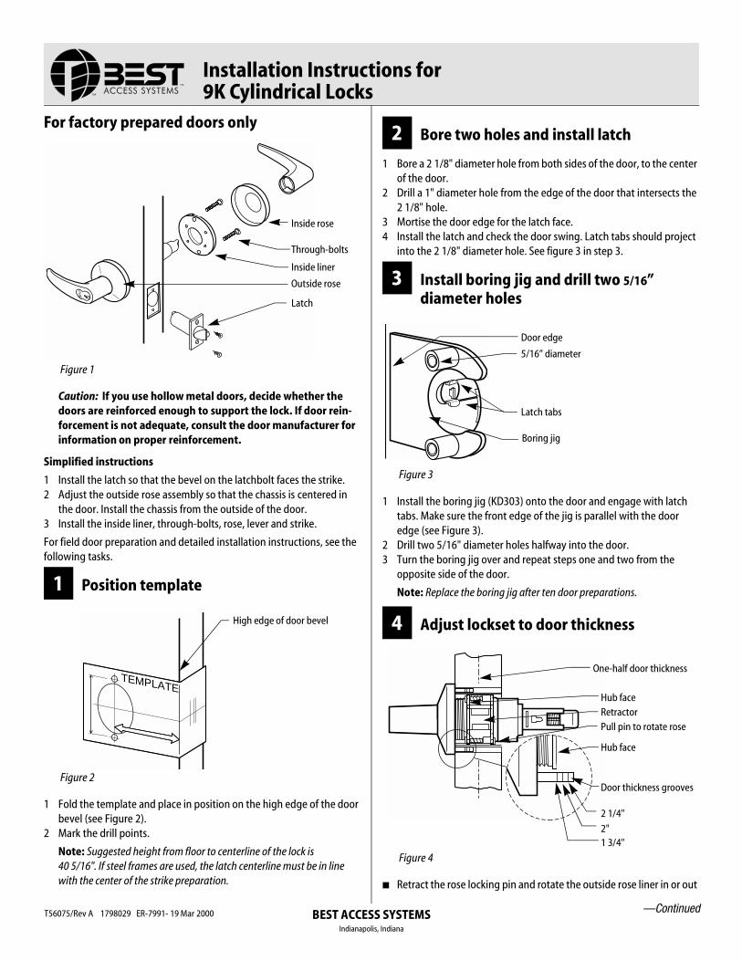
Installation Instructions for
9K Cylindrical Locks
For factory prepared doors only
Caution: If you use hollow metal doors, decide whether the doors are reinforced enough to support the lock. If door rein-forcement is not adequate, consult the door manufacturer for information on proper reinforcement.
Simplified instructions
1 Install the latch so that the bevel on the latchbolt faces the strike.2 Adjust the outside rose assembly so that the chassis is centered in
the door. Install the chassis from the outside of the door.3 Install the inside liner, through-bolts, rose, lever and strike.
For field door preparation and detailed installation instructions, see the following tasks.
1 Position template
1 Fold the template and place in position on the high edge of the door bevel (see Figure 2).
2 Mark the drill points.
Note: Suggested height from floor to centerline of the lock is 40 5/16". If steel frames are used, the latch centerline must be in line with the center of the strike preparation.
2 Bore two holes and install latch
1 Bore a 2 1/8" diameter hole from both sides of the door, to the center of the door.
2 Drill a 1" diameter hole from the edge of the door that intersects the 2 1/8" hole.
3 Mortise the door edge for the latch face.4 Install the latch and check the door swing. Latch tabs should project
into the 2 1/8" diameter hole. See figure 3 in step 3.
3 Install boring jig and drill two 5/16” diameter holes
1 Install the boring jig (KD303) onto the door and engage with latch tabs. Make sure the front edge of the jig is parallel with the door edge (see Figure 3).
2 Drill two 5/16" diameter holes halfway into the door.3 Turn the boring jig over and repeat steps one and two from the
opposite side of the door.
Note: Replace the boring jig after ten door preparations.
4 Adjust lockset to door thickness
■ Retract the rose locking pin and rotate the outside rose liner in or out
Figure 1
Figure 2
Inside rose
Inside liner
Latch
Through-bolts
Outside rose
TEMPLATE
High edge of door bevel
Figure 3
Figure 4
Door edge
5/16” diameter
Latch tabs
Boring jig
One-half door thickness
Hub faceRetractorPull pin to rotate rose
Hub face
2 1/4"
2"1 3/4"
Door thickness grooves
—Continued
BEST ACCESS SYSTEMSIndianapolis, IndianaT56075/Rev A 1798029 ER-7991- 19 Mar 2000
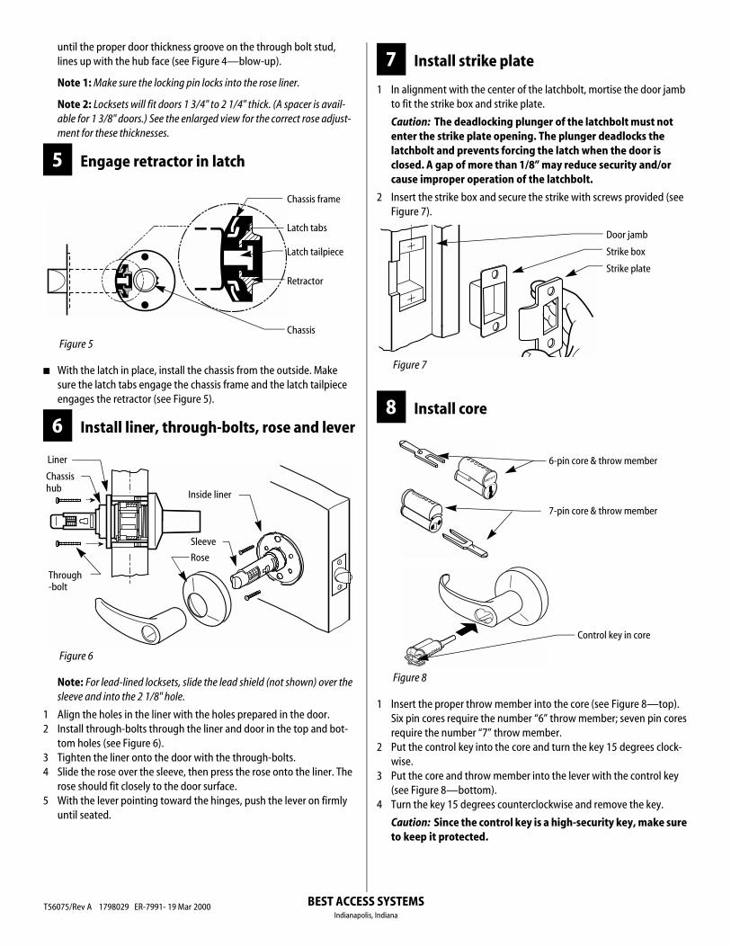
BEST ACCESS SYSTEMS
until the proper door thickness groove on the through bolt stud, lines up with the hub face (see Figure 4—blow-up).
Note 1: Make sure the locking pin locks into the rose liner.
Note 2: Locksets will fit doors 1 3/4" to 2 1/4" thick. (A spacer is avail-able for 1 3/8" doors.) See the enlarged view for the correct rose adjust-ment for these thicknesses.
5 Engage retractor in latch
■ With the latch in place, install the chassis from the outside. Make sure the latch tabs engage the chassis frame and the latch tailpiece engages the retractor (see Figure 5).
6 Install liner, through-bolts, rose and lever
Note: For lead-lined locksets, slide the lead shield (not shown) over the sleeve and into the 2 1/8" hole.
1 Align the holes in the liner with the holes prepared in the door.2 Install through-bolts through the liner and door in the top and bot-
tom holes (see Figure 6).3 Tighten the liner onto the door with the through-bolts.4 Slide the rose over the sleeve, then press the rose onto the liner. The
rose should fit closely to the door surface.5 With the lever pointing toward the hinges, push the lever on firmly
until seated.
7 Install strike plate
1 In alignment with the center of the latchbolt, mortise the door jamb to fit the strike box and strike plate.
Caution: The deadlocking plunger of the latchbolt must not enter the strike plate opening. The plunger deadlocks the latchbolt and prevents forcing the latch when the door is closed. A gap of more than 1/8” may reduce security and/or cause improper operation of the latchbolt.
2 Insert the strike box and secure the strike with screws provided (see Figure 7).
8 Install core
1 Insert the proper throw member into the core (see Figure 8—top). Six pin cores require the number “6” throw member; seven pin cores require the number “7” throw member.
2 Put the control key into the core and turn the key 15 degrees clock-wise.
3 Put the core and throw member into the lever with the control key (see Figure 8—bottom).
4 Turn the key 15 degrees counterclockwise and remove the key.
Caution: Since the control key is a high-security key, make sure to keep it protected.
Figure 5
Figure 6
Chassis frame
Latch tabs
Latch tailpiece
Retractor
Chassis
Chassis
Through
Inside liner
Sleeve
Rose
Liner
hub
-bolt
Figure 7
Figure 8
Door jamb
Strike box
Strike plate
BEST
6-pin core & throw member
7-pin core & throw member
Control key in core
Indianapolis, IndianaT56075/Rev A 1798029 ER-7991- 19 Mar 2000
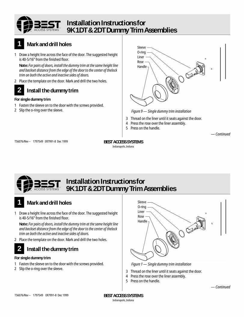
Installation Instructions for 9K 1DT & 2DT Dummy Trim Assemblies
1 Mark and drill holes
1 Draw a height line across the face of the door. The suggested height is 40-5/16” from the finished floor.
Note: For pairs of doors, install the dummy trim at the same height line and backset distance from the edge of the door to the center of thelock trim on both the active and inactive sides of doors.
2 Place the template on the door. Mark and drill the two holes.
2 Install the dummy trim
For single dummy trim
1 Fasten the sleeve on to the door with the screws provided.2 Slip the o-ring over the sleeve.
3 Thread on the liner until it seats against the door.4 Press the rose over the liner assembly.5 Press on the handle.
— Continued
Figure 9 — Single dummy trim installation
LinerRoseHandle
SleeveO-ring
BEST ACCESS SYSTEMSIndianapolis, Indiana
Installation Instructions for 9K 1DT & 2DT Dummy Trim Assemblies
T56076/Rev – 1797549 ER7991-8 Dec 1999
1 Mark and drill holes
1 Draw a height line across the face of the door. The suggested height is 40-5/16” from the finished floor.
Note: For pairs of doors, install the dummy trim at the same height line and backset distance from the edge of the door to the center of thelock trim on both the active and inactive sides of doors.
2 Place the template on the door. Mark and drill the two holes.
2 Install the dummy trim
For single dummy trim
1 Fasten the sleeve on to the door with the screws provided.2 Slip the o-ring over the sleeve.
3 Thread on the liner until it seats against the door.4 Press the rose over the liner assembly.5 Press on the handle.
— Continued
Figure 1 — Single dummy trim installation
LinerRoseHandle
SleeveO-ring
BEST ACCESS SYSTEMSIndianapolis, Indiana
T56076/Rev – 1797549 ER7991-8 Dec 1999
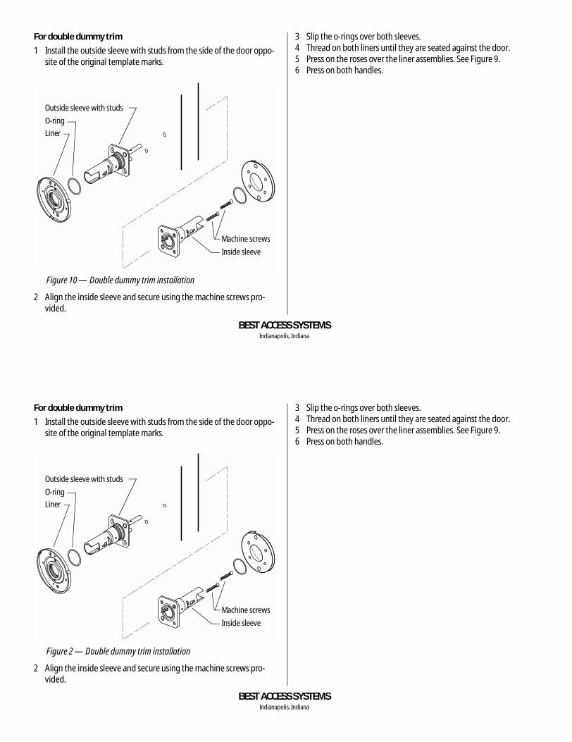
For double dummy trim
1 Install the outside sleeve with studs from the side of the door oppo-site of the original template marks.
2 Align the inside sleeve and secure using the machine screws pro-vided.
3 Slip the o-rings over both sleeves.4 Thread on both liners until they are seated against the door.5 Press on the roses over the liner assemblies. See Figure 9.6 Press on both handles.
Figure 10 — Double dummy trim installation
Outside sleeve with studs
Liner
O-ring
Machine screws
Inside sleeve
BEST ACCESS SYSTEMSIndianapolis, Indiana
For double dummy trim
1 Install the outside sleeve with studs from the side of the door oppo-site of the original template marks.
2 Align the inside sleeve and secure using the machine screws pro-vided.
3 Slip the o-rings over both sleeves.4 Thread on both liners until they are seated against the door.5 Press on the roses over the liner assemblies. See Figure 9.6 Press on both handles.
Figure 2 — Double dummy trim installation
Outside sleeve with studs
Liner
O-ring
Machine screws
Inside sleeve
BEST ACCESS SYSTEMSIndianapolis, Indiana
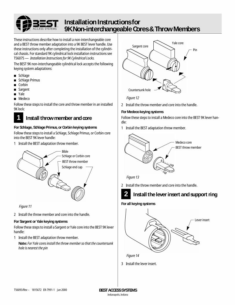
Installation Instructions for 9K Non-interchangeable Cores & Throw Members
These instructions describe how to install a non-interchangeable core and a BEST throw member adaptation into a 9K BEST lever handle. Use these instructions only after completing the installation of the cylindri-cal chassis. For standard 9K cylindrical lock installation instructions see T56075 — Installation Instructions for 9K Cylindrical Locks.
The BEST 9K non-interchangeable cylindrical lock accepts the following keying system adaptations:
■ Schlage■ Schlage Primus■ Corbin■ Sargent■ Yale■ Medeco
Follow these steps to install the core and throw member in an installed 9K lock:
1 Install throw member and core
For Schlage, Schlage Primus, or Corbin keying systems
Follow these steps to install a Schlage, Schlage Primus, or Corbin core into the BEST 9K lever handle:
1 Install the BEST adaptation throw member.
2 Install the throw member and core into the handle.
For Sargent or Yale keying systems
Follow these steps to install a Sargent or Yale core into the BEST 9K lever handle:
1 Install the BEST adaptation throw member.
Note: For Yale cores install the throw member so that the countersunk hole is nearest the pin
.
2 Install the throw member and core into the handle.
For Medeco keying systems
Follow these steps to install a Medeco core into the BEST 9K lever han-dle:
1 Install the BEST adaptation throw member.
2 Install the throw member and core into the handle.
2 Install the lever insert and support ring
For all keying systems
3 Install the lever insert.
Figure 11
BibleSchlage or Corbin core
BEST throw member
Schlage end cap
Figure 12
Figure 13
Figure 14
Yale coreSargent core
Pin
Countersunk hole
Medeco core
BEST throw member
Lever insert
BEST ACCESS SYSTEMSIndianapolis, Indiana
T56093/Rev – 1815672 ER-7991-1 Jan 2000
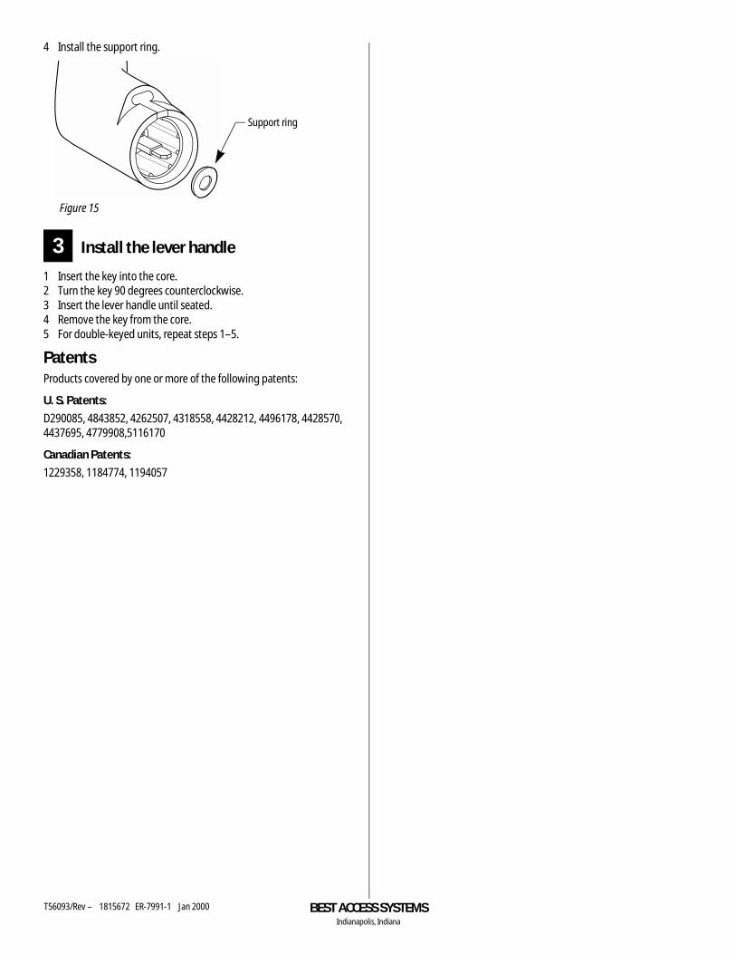
4 Install the support ring.
3 Install the lever handle
1 Insert the key into the core.2 Turn the key 90 degrees counterclockwise.3 Insert the lever handle until seated.4 Remove the key from the core.5 For double-keyed units, repeat steps 1–5.
PatentsProducts covered by one or more of the following patents:
U. S. Patents:
D290085, 4843852, 4262507, 4318558, 4428212, 4496178, 4428570, 4437695, 4779908,5116170
Canadian Patents:
1229358, 1184774, 1194057
Figure 15
Support ring
BEST ACCESS SYSTEMSIndianapolis, Indiana
T56093/Rev – 1815672 ER-7991-1 Jan 2000
B
9K Series Service
INDEX
AA chassis
function conversion for 2–43function description for 2–7part numbers and drawings for 2–25
AB chassisfunction conversion for 2–42function description for 2–2part numbers and drawings for 2–10
aligning the chassis and trim 3–19
BB chassis
function conversion for 2–43function description for 2–7part numbers and drawings for 2–26
boring jig kit 2–54bridge bar 2–32button assembly
button release assembly 2–16locking bar assembly for NX function
2–18outside button assembly for LL function
2–31push button assembly 2–15 to 2–16,
2–19, 2–22, 2–26, 2–31slotted button assembly 2–13, 2–29turn button assembly 2–10, 2–25, 2–33
button bar assemblyreinstalling 3–8removing 3–7
CC chassis
cam positioning instructions for 3–20function conversion for 2–42function description for 2–4part numbers and drawings for 2–11
cam positioning instructionsfor C chassis 3–20for G and IN chassis 3–21
certifications and standards 1–1chassis cover 2–10 to 2–40chassis screw 2–10 to 2–40cores, lubricating 3–18
DD chassis
function conversion for 2–42function description for 2–2part numbers and drawings for 2–12
diagrams, explodedsee part numbers and drawings
disassembling the lock chassis 3–11documentation package 1–2double dummy trim 2–6, 2–51DR chassis
function conversion for 2–43function description for 2–8part numbers and drawings for 2–27
drawings, of partssee part numbers and drawings
drill jig 2–53drive plate
see spring drive plate
Manual B-1
Index
DZ chassisfunction conversion for 2–43function description for 2–7part numbers and drawings for
2–28
EE chassis
function conversion for 2–42function description for 2–3part numbers and drawings for
2–13EA chassis
function conversion for 2–43function description for 2–7part numbers and drawings for
2–29emergency driver 3–2exploded diagrams
see part numbers and drawings
Ffaceplate marking chisel 2–53function description
for A chassis 2–7for AB chassis 2–2for B chassis 2–7for C chassis 2–4for D chassis 2–2for DR chassis 2–8for DZ chassis 2–7for E chassis 2–3for EA chassis 2–7for G chassis 2–4for H and HJ chassis 2–3for IN chassis 2–4for L chassis 2–6for LL chassis 2–8for M chassis 2–9for N chassis 2–6for NX chassis 2–6for P chassis 2–6for Q chassis 2–9for R chassis 2–3for RD chassis 2–8for RZ chassis 2–8for S chassis 2–4for T chassis 2–3for W chassis 2–5for XD chassis 2–8for XR chassis 2–8for Y chassis 2–6for YD chassis 2–8for YR chassis 2–8for Z chassis 2–9
GG chassis
cam positioning instructionsfor 3–21
function conversion for 2–42function description for 2–4part numbers and drawings for
2–14
HH and HJ chassis
function conversion for 2–42function description for 2–3key instructions for 3–22part numbers and drawings for
2–15hub
see inside hub assembly andoutside hub
IIN chassis
cam positioning instructionsfor 3–21
function conversion for 2–43function description for 2–4part numbers and drawings for
2–30inside hub assembly
inside hub and locking pin as-sembly 2–10 to 2–27,2–29 to 2–34, 2–36 to 2–39
inside hub and locking pin as-sembly, lost motion 2–30, 2–32
inside hub and side plate assem-bly 2–28, 2–35, 2–40
inside hub assembly, lost mo-tion 2–11, 2–14, 2–21, 2–23, 2–27, 2–34, 2–36 to 2–39
Kkey instructions for H and HJ chassis
3–22key release cam assembly
part number and drawing for2–10 to 2–16, 2–18 to 2–23, 2–25 to 2–39
reinstalling 3–15removing 3–14
LL chassis
function conversion for 2–42function description for 2–6part numbers and drawings for
2–16lever handle insert 2–50lever keeper spring 2–48, 3–9lever return spring
part number and drawing for2–10 to 2–22, 2–24 to 2–27, 2–29 to 2–35,2–37, 2–39 to 2–40
reinstalling 3–12removing 3–10
leverspart drawings for 2–47part numbers for 2–47, 2–49reinstalling 3–3removing 3–3
LL chassisfunction conversion for 2–43function description for 2–8part numbers and drawings for
2–31lock chassis
aligning 3–19disassembling 3–11reassembling 3–13reinstalling in the door 3–7removing from the door 3–6
locking bar 2–11, 2–14, 2–30lubricating cores 3–18
MM chassis
function conversion for 2–43function description for 2–9part numbers and drawings for
2–32
NN chassis
function conversion for 2–42function description for 2–6part numbers and drawings for
2–17numbers, for parts
see part numbers and drawingsNX chassis
function conversion for 2–42function description for 2–6part numbers and drawings for
2–18
B-2 9K Series Service Manual
Index
Ooutside hub
outside hub 2–10 to 2–23, 2–25 to 2–40
outside hub and plate assembly 2–24
outside hub, lost motion 2–10to 2–16, 2–18 to 2–23, 2–25 to 2–32,2–34 to 2–37
PP chassis
function conversion for 2–42function description for 2–6part numbers and drawings for
2–19part numbers and drawings
for A chassis 2–25for AB chassis 2–10for B chassis 2–26for C chassis 2–11for D chassis 2–12for double dummy trim 2–51for DR chassis 2–27for DZ chassis 2–28for E chassis 2–13for EA chassis 2–29for G chassis 2–14for H and HJ chassis 2–15for IN chassis 2–30for L chassis 2–16for latches 2–52for LL chassis 2–31for M chassis 2–32for N chassis 2–17for non-IC levers 2–49for non-standard strikes 2–44for NX chassis 2–18for P chassis 2–19for Q chassis 2–33for R chassis 2–20for RD chassis 2–34for roses, rose liners, and rose
spacers 2–45 to 2–46for RZ chassis 2–35for S chassis 2–21for single dummy trim 2–51for standard levers 2–47for standard strikes and strike
boxes 2–44for T chassis 2–22for W chassis 2–23for XD chassis 2–36for XR chassis 2–37
for Y chassis 2–24for YD chassis 2–38for YR chassis 2–39for Z chassis 2–40
QQ chassis
function conversion for 2–43function description for 2–9part numbers and drawings for
2–33
RR chassis
function conversion for 2–42function description for 2–3part numbers and drawings for
2–20RD chassis
function conversion for 2–43function description for 2–8part numbers and drawings for
2–34reassembling the lock chassis 3–13reinstalling
button bar assembly 3–8inside rose and rose liner 3–5key release cam assembly 3–15keyed lever 3–3lever keeper spring 3–9lever return spring 3–12lock chassis in the door 3–7outside rose and liner assembly
3–6sleeve assembly 3–17spring drive plate 3–16thrust plate 3–13
removingbutton bar assembly 3–7inside rose and rose liner 3–4key release cam assembly 3–14keyed lever 3–3lever keeper spring 3–9lever return spring 3–10lock chassis from the door 3–6outside rose and liner assembly
3–5plain lever or button lever 3–3sleeve assembly 3–16spring drive plate 3–15thrust plate 3–11
retractor assemblywith long catchplate 2–10,
2–13 to 2–16, 2–19,2–22 to 2–23, 2–31
with short catchplate 2–26, 2–29
without catchplate 2–11 to 2–12, 2–17 to 2–18,2–20 to 2–21, 2–24 to 2–25, 2–27 to 2–28,2–30, 2–32 to 2–40
RZ chassisfunction conversion for 2–43function description for 2–8part numbers and drawings for
2–35
SS chassis
function conversion for 2–42function description for 2–4part numbers and drawings for
2–21single dummy trim 2–6, 2–51sleeve assembly
keyed sleeve and driver assem-bly 2–18
keyed sleeve assembly 2–10 to2–16, 2–19 to 2–23,2–25 to 2–30, 2–33 to 2–39
keyed sleeve assembly for Mfunction 2–31 to 2–32
keyed sleeve assembly, non-IC2–10 to 2–14, 2–20 to 2–23, 2–25 to 2–30,2–34 to 2–39
non-keyed sleeve and driver as-sembly 2–10, 2–12 to2–13, 2–15 to 2–20,2–22, 2–24 to 2–26,2–29, 2–31 to 2–33,2–40
non-keyed sleeve and driver as-sembly 2–28, 2–35,2–40
reinstalling 3–17removing 3–16sleeve and key release cam as-
sembly 2–11sleeve and key release cam as-
sembly, non-IC 2–11spanner wrench
part number for 3–2using 3–3 to 3–4
spring drive platepart number and drawing for
2–10 to 2–16, 2–18 to 2–23, 2–25 to 2–39
9K Series Service Manual B-3
Index
reinstalling 3–16removing 3–15
spring loading tool 3–2, 3–12strike plate locating pin 2–53support, technical 1–2
TT chassis
function conversion for 2–42function description for 2–3part numbers and drawings for
2–22technical documentation package
1–2technical support 1–2throw member 2–31, 2–48, 2–50throw member support ring 2–50thrust plate
part number and drawing for2–10 to 2–40
reinstalling 3–13removing 3–11
troubleshooting questions 3–23turn blade assembly for Z function
2–28, 2–35, 2–40
WW chassis
function conversion for 2–42function description for 2–5part numbers and drawings for
2–23
XXD chassis
function conversion for 2–43function description for 2–8part numbers and drawings for
2–36XR chassis
function conversion for 2–43function description for 2–8part numbers and drawings for
2–37
YY chassis
function conversion for 2–42function description for 2–6part numbers and drawings for
2–24
YD chassisfunction conversion for 2–43function description for 2–8part numbers and drawings for
2–38YR chassis
function conversion for 2–43function description for 2–8part numbers and drawings for
2–39
ZZ chassis
function conversion for 2–43function description for 2–9part numbers and drawings for
2–40
B-4 9K Series Service Manual