95-2009 instructions for part 95-2009 95-2009 applications gm/suzuki multi kit kit features •...
TRANSCRIPT

INSTALLATION INSTRUCTIONS FOR PART 95-2009
95-2009
APPLICATIONSGM/SUZUKI MULTI KIT
KIT FEATURES
• Double DIN Radio Provision• Stacked ISO Mount Units Provision
• A) Double DIN Brackets • B) Double DIN Trim Plate • C) Spacers • D) (4) Carriage Bolts • E) (4) Kep Nuts • F) (3) Screws-(3) Speed Clips
KIT COMPONENTS
A
TOOLS REQUIRED:Utility knife • Phillips Screwdriver • Socket Set
1-800-221-0932 © COPYRIGHT 2004-2009 METRA ELECTRONICS CORPORATION
www.metraonline.com
BC
D
E F
WIRING AND ANTENNA CONNECTIONS(Sold Separately)• Wiring Harness - Please see www.metraonline.com
for specific interface applications• Antenna Adapter -• 40-GM10 - GM Antenna Adapter 1988-up • 40-CR10 - Chrysler Antenna Adapter 2002-up

BUICKCentury 1997-2005 3 Le Sabre 1995-2005 4Park Avenue 1995-2005 5Rainier 2004-2007 28Regal 1995-2004 3Rendezvous 2002-2007 6Riviera 1996-1999 7Roadmaster 1995-1996 8Skylark 1996-1998 9
CADILLACEscalade/EXT 2003-2006 10 Fleetwood/Broughham 1990-1996 11-12Eldorado 1992-1995 13Seville 1992-1995 13
CHEVROLET Avalanche 2003-2006 10Blazer 2002-2005 14Cavalier 2000-2005 15Colorado 2004-2010 16Express Van (full size) 2001-2007 17,18Impala 2000-2005 19Malibu 2001-2003 20Malibu Classic 2004 20Metro (Geo included) 1995-2001 21Monte Carlo 2000-2005 22SSR 2003-2006 23S-10 Pickup with DDIN Radio 2002-2004 14Silverado (all) 2003-2007 10Suburban 2003-2006 10Tahoe 2003-2006 10Tracker 1992-2004 24Trailblazer 2002-2009 25Venture 2000-2005 26,27
GMCCanyon 2004-2010 16Envoy 2002-2009 28Savanna 2001-2007 17,18Sierra 2003-2007 10Sonoma 2002-2004 14Yukon/Denali/XL 2003-2006 10
HONDAPassport 1998-2002 29
HUMMERH2 2003-2007 30,31ISUZUAscender 2003-2009 28Amigo 1998-2000 29I-290/I370 2007-2008 16I-280/I350 2006 16Rodeo 1998-2004 29Rodeo Sport 2001-2003 29
OLDSMOBILEAchieva 1996-1998 32Alero 1999-2004 33Aurora 1995-2003 34Bravada 1998-2001 14Bravada 2002-2004 28Cutlass 1997-1999 35Cutlass Supreme 1995-1997 35Eighty-Eight 1994-1999 36Intrigue 1998-2003 37LSS 1996-1999 38Ninety-Eight 1994-1996 36Regency 1997-1998 38Silhouette 2000-2004 26,27
PONTIACAztec 2001-2005 39Bonneville 2000-2005 40Grand Am 2001-2005 41Montana 2000-2005 26,27Sunfire 2000-2005 42
SSUZUKIAerio 2002 44Esteem 1995-2003 45Sidekick 1992-1998 24Swift 1995-2001 21Vitara 1999-2005 24Grand Vitara 1999-2002 24XL-7 2001-2002 24TTOOYYOOTTAAMatrix 2003-2004 43
TTaabb IInnssttrruuccttiioonnss
CHEVY/GM/METRO/SUZUKI/CADILLAC - FLEETWOOD/BROUGHHAM . . . . . . . . 46ISUZU/PONTIAC/TOYOTA/CADILLAC - ELDORADO/SEVILLE . . . . . . . . . . . . . 47
Kit AssemblyCADILLAC - FLEETWOOD/BROUGHHAM . . . . . . . . 48CADILLAC - ELDORADO/SEVILLE . . . . . . . . . . . . . 49DOUBLE DIN RADIO/STACKED ISO MOUNT UNITSPROVISION . . . . . . . . . . . . . . . . . . . . . . . . . . . . . . . . . .50
Final Assembly . . . . . . . . . . . . . . . . . . . . . . . . . . . . . .51
95-2009
*Note: Refer also to the instructions included with the aftermarket radio.
KNOWLEDGE IS POWEREnhance your installation and fabrication skills by enrolling in the most recognized and respected mobile electronics school in our industry.Log onto www.installerinstitute.com or call 800-354-6782 for more information and take steps toward a better tomorrow.
Vibe 2003-2008 43
VEHICLE APPLICATION CONTENTS
Dash Disassembly

95-2009 DASH DISASSEMBLY
BUICK • CENTURY 1997-2005 / REGAL 1995-2004
3
1
Unsnap the top edge of the knee bolster panel.
Disconnect the negative battery terminal to prevent an accidentalshort circuit.
3
Remove the plastic trim piece to theleft of the glove box and (1) Phillipsscrew exposed.
2
Remove (1) Phillips screw from thepanel.
4
Remove the ashtray cluster and (2)Phillips screws from each side.
5
Unclip the entire dash trim bezel andremove.
6
Open doors and unsnap end capsfrom each side of dash.
7
Unsnap and remove radio/instrumentcluster panel.
8
Remove (3) screws in order to removeradio.
9
Continue to kit assembly.

4
95-2009 DASH DISASSEMBLY
BUICK • LESABRE / PARK AVENUE 1995-1999
1
Pop out the a/c vents and remove (1)Phillips screw exposed in each ventcavity.
Disconnect the negative battery terminal to prevent an accidentalshort circuit.
3
Unsnap the climate control trim panel(from door to door) and remove (4) Phillips screws exposed.
2
Unclip the radio trim bezel and remove. 4
Remove the screws securing the fac-tory head unit and disconnect thewiring.
5
Continue to kit assembly.

5
95-2009 DASH DISASSEMBLY
BUICK • LESABRE / PARK AVENUE 2000-2005
1
Unsnap and remove trim along centerof dash. (One piece on right and oneon left of wheel)
Disconnect the negative battery terminal to prevent an accidentalshort circuit.
3
Open drivers door and unsnap andremove dash end cap.
2
Unsnap and remove radio/instrumentbezel.
4
Remove (2) screws in order to removeradio.
5
Continue to kit assembly.
6
95-2009 DASH DISASSEMBLY
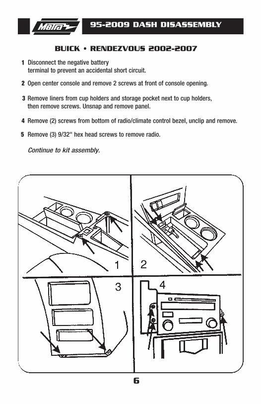
BUICK • RENDEZVOUS 2002-2007
1
Remove liners from cup holders and storage pocket next to cup holders,then remove screws. Unsnap and remove panel.
Disconnect the negative battery terminal to prevent an accidental short circuit.
3
Open center console and remove 2 screws at front of console opening.2
Remove (2) screws from bottom of radio/climate control bezel, unclip and remove.4
Remove (3) 9/32" hex head screws to remove radio.5
Continue to kit assembly.

7
95-2009 DASH DISASSEMBLY
1
Remove (1) Phillips screw and unsnap right side panel to expose (1) Phillips screwbeneath panel and remove.
Disconnect the negative battery terminal to prevent an accidental short circuit.
3
Unsnap left side panel exposing (1) Phillips screw to remove.2
Unsnap underside of overhanging dash to unsnap (6) plastic rivets and removepanel.
4
Remove (5) hex head screws now exposed under overhang.5
Unsnap bottom edge of trim bezel, then while holding overhang up, unsnap andremove trim bezel by removing any necessary harnesses.
6
Remove (3) Phillips screw to remove climate control.7
Remove (2) Phillips screws to remove rear support and (3) 9/32" hex head screwsto remove radio.
8
Continue to kit assembly.
BUICK • RIVIERA 1996-

8
95-2009 DASH DISASSEMBLY
1
Unclip panel below steering column and remove.
Disconnect the negative battery terminal to prevent an accidental short circuit.
3
Unclip dash panel sides and remove.2
Remove (2) 7mm screws above instrument cluster.4
Set parking brake, turn car on, and move shifter to the lowest gear. Tilt steering wheel down then unsnap entire instrument cluster/radio panel and remove.
5
Remove (3) 7mm screws to remove radio.6
Continue to kit assembly.
BUICK • ROADMASTER 1995-1996

9
95-2009 DASH DISASSEMBLY
1
Under glove box and drivers knee bol-ster, remove (2) plastic panels by turning (2) 1/4 turn fasteners per side.
Disconnect the negative battery terminal to prevent an accidentalshort circuit.
3
Remove (6) 9/32" screws inside glovebox.
2
Remove (4) 9/32" screws revealed.(2 per side).
4
Unsnap panel from driver's side topassenger's side.
5
Remove (3) 9/32" screws to removeradio.
6
Continue to kit assembly.
BUICK • SKYLARK 1996-1998
10
95-2009 DASH DISASSEMBLY
1
Remove (3) 9/32" screws and removeradio.
Disconnect the negative battery terminal to prevent an accidentalshort circuit.
3
Unsnap and remove dash bezel.2
Continue to kit assembly.
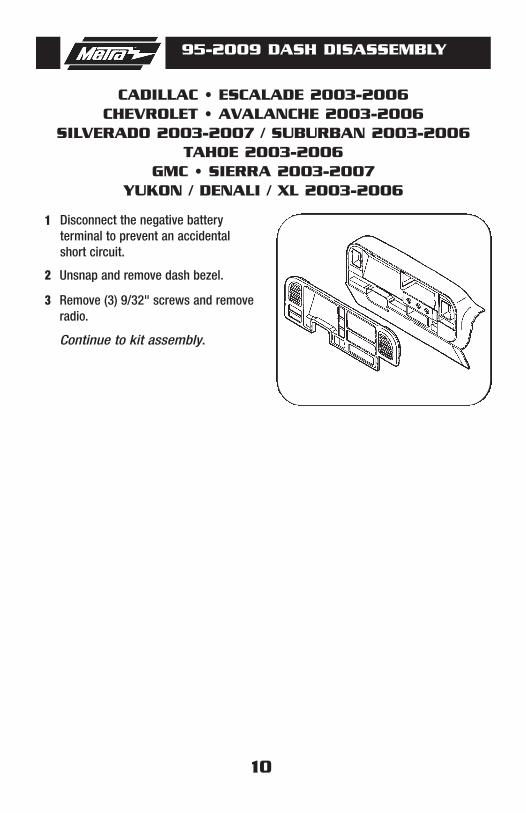
CADILLAC • ESCALADE 2003-2006CHEVROLET • AVALANCHE 2003-2006
SILVERADO 2003-2007 / SUBURBAN 2003-2006TAHOE 2003-2006
GMC • SIERRA 2003-2007YUKON / DENALI / XL 2003-2006

11
95-2009 DASH DISASSEMBLY
1
Remove (2) 7mm screws at the top of the radio/air conditioning bezel, then unclip panel and remove.
Disconnect the negative battery terminal to prevent an accidental short circuit.
3
Carefully unsnap trim panel above a/c controls.2
Remove (4) 7mm screws that hold the radio in, slide radio out, unplug the radio harnesses and remove radio.
4
Continue to kit assembly.
CADILLAC • FLEETWOODFLEETWOOD BROUGHAM 1990-1996

12
95-2009 DASH DISASSEMBLY
1 Remove (4) 10mm nuts, (2) on top of the radio and (2) on the bottom of the radio,that hold the factory mounting brackets on. save brackets and nuts for kit assembly.
CADILLAC • FLEETWOODFLEETWOOD BROUGHAM 1990-1996RADIO BRACKET DISASSEMBLY
13
95-2009 DASH DISASSEMBLY
11
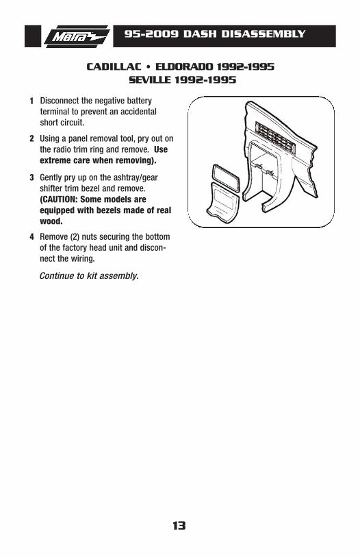
Gently pry up on the ashtray/gearshifter trim bezel and remove. (CAUTION: Some models areequipped with bezels made of realwood.
Disconnect the negative battery terminal to prevent an accidentalshort circuit.
3
Using a panel removal tool, pry out onthe radio trim ring and remove. Useextreme care when removing).
2
Remove (2) nuts securing the bottomof the factory head unit and discon-nect the wiring.
4
CADILLAC • ELDORADO 1992-1995SEVILLE 1992-1995
Continue to kit assembly.

14
95-2009 DASH DISASSEMBLY
1
Pull down on the panel and removethe 9/32" hex-head screws exposedon the bottom of the dash trim bezel.
Disconnect the negative battery terminal to prevent an accidentalshort circuit.
3
Remove (2) 9/32" hex-head screwsfrom the knee bolster panel.
2
Remove (1) Phillips screw above theinstrument cluster.
4
Unclip the dash trim bezel andremove.
5
Remove (2) 9/32" hex-head screwssecuring the factory head unit anddisconnect the wiring.
6
CHEVROLET • BLAZER 2002-2005 S-10 2002-2004 (WITH DOUBLE DIN RADIO)
GMC • SONOMA 2002-2004OLDSMOBILE • BRAVADA 1998-2001
Continue to kit assembly.

15
95-2009 DASH DISASSEMBLY
1
Open passenger door and remove panel on end of dash.
Disconnect the negative battery terminal to prevent an accidental short circuit.
3
Open drivers door and remove fuse panel on end of dash. 2
Remove (1) Phillips screw from each side exposed. 4
Remove (3) screws from top of glove box liner. 5
Remove (2) screws from the top-left corner of the glove box cavity. 6
Remove (1) Phillips screw from the defroster duct. 7
Remove the ductwork and (1) Phillips screw exposed. 8
Remove the dash pad and (3) Phillips screws exposed at the top of the radio trimbezel.
9
CHEVROLET • CAVALIER 2000-2005
Continue to kit assembly.
95-2009 DASH DISASSEMBLY
16
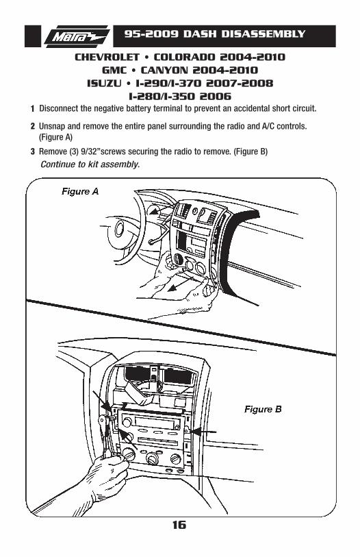
1
Remove (3) 9/32”screws securing the radio to remove. (Figure B)
Disconnect the negative battery terminal to prevent an accidental short circuit.
3
Unsnap and remove the entire panel surrounding the radio and A/C controls. (Figure A)
2
CHEVROLET • COLORADO 2004-2010GMC • CANYON 2004-2010
ISUZU • I-290/I-370 2007-2008I-280/I-350 2006
Continue to kit assembly.

17
95-2009 DASH DISASSEMBLY
1
Unsnap radio/climate/instrument panel.
Disconnect the negative battery terminal to prevent an accidental short circuit.
3
Unsnap and remove small trim panel below steering column.2
Move shift lever to first gear position.4
Rotate panel counterclockwise to lift over steering column and remove.5
Remove (3) 9/32" hex head screws to remove radio.6
Continue to kit assembly.
CHEVROLET • EXPRESS VAN 2001-2002GMC • SAVANNA 2001-2002

18
95-2009 DASH DISASSEMBLY
1
Remove (2) 10mm bolts from panel below passenger dash airbag and removepanel.
Disconnect the negative battery terminal to prevent an accidental short circuit.
3
Remove (2) 10mm bolts from below knee bolster under steering column and remove panel.
2
Remove (2) 10mm nuts from inside center pocket between power outlets.4
Unsnap and remove radio and instrument cluster panel. (May not be necessaryto completely remove radio and instrument cluster panel to access radio.)
5
Remove (3) 9/32" bolts to remove radio.6
Continue to kit assembly.
CHEVROLET • EXPRESS VAN 2003-2007GMC • SAVANNA 2003-2007

19
95-2009 DASH DISASSEMBLY
1
Remove (2) Phillips screws under theinstrument cluster.
Disconnect the negative batteryterminal to prevent an accidentalshort circuit.
3
Unclip each side of the dash trimbezel (fuse access) and remove (1)Phillips screw exposed on each side.
2
Unclip the trim panel above thepedals. (It is not necessary to removethe panel it can be left hanging).
4
Remove (2) Phillips screws from theknee panel.
5
Unclip the knee panel and remove (1)phillips screw exposed on the rightside of the steering column.
6
Unclip and remove the entire dashtrim bezel.
7
CHEVROLET • IMPALA 2000-2005
Continue to kit assembly.
20
95-2009 DASH DISASSEMBLY
1
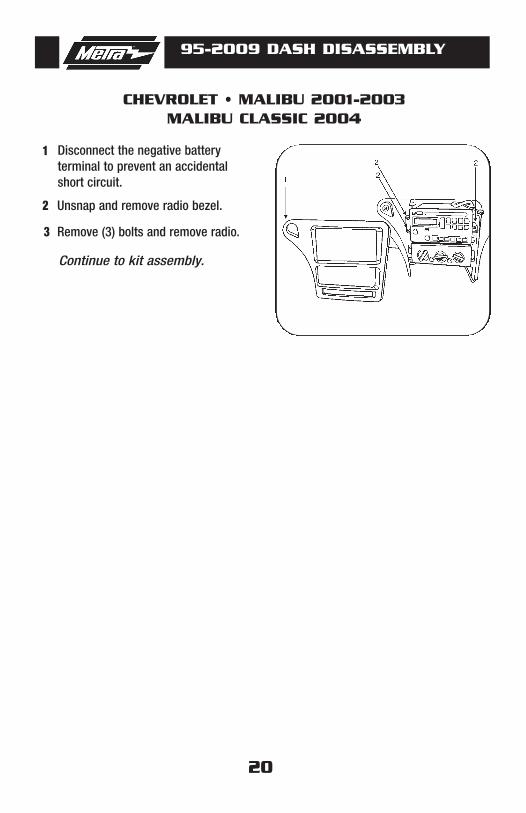
Remove (3) bolts and remove radio.
Disconnect the negative batteryterminal to prevent an accidentalshort circuit.
3
Unsnap and remove radio bezel.2
CHEVROLET • MALIBU 2001-2003MALIBU CLASSIC 2004
Continue to kit assembly.

21
95-2009 DASH DISASSEMBLY
1
Remove (2) Phillips screws above theradio opening.
Disconnect the negative batteryterminal to prevent an accidentalshort circuit.
3
Remove the ashtray and (2) Phillipsscrews exposed.
2
Unclip the radio trim bezel and disconnect the cigarette lighterwiring.
4
Remove (2) screws securing eachside of the factory head unit and (1)screw from the rear support.
5
Slide the unit out and disconnect thewiring.
6
CHEVROLET • METRO 1995-2001SUZUKI • SWIFT 1995-2001
Continue to kit assembly.

22
95-2009 DASH DISASSEMBLY
1
Remove (2) 9/32" screws from theknee panel and unclip the panel.
Disconnect the negative batteryterminal to prevent an accidentalshort circuit.
3
Unclip the trim panel above the ped-als. (It is NOT necessary to removethe panel it may be left hanging).
2
Unsnap the driver's side fuse panelcover and remove (1) 9/32" screw.
4
Open the glove box and remove (1)9/32" screw from the upper left corner.
5
Remove (3) 9/32" screws securingthe factory radio and disconnect thewiring.
6
CHEVROLET • MONTE CARLO 2000-2005
Continue to kit assembly.

23
95-2009 DASH DISASSEMBLY
1 23
1 23
1
Unclip and remove the long trim panelbelow the radio and passenger airbag. (Figure B)
Disconnect the negative batteryterminal to prevent an accidentalshort circuit.
3
Unclip and remove the (3) climatecontrol knobs. (Figure A)
2
Unclip and remove the small trimpanel to the left of the steeringwheel. (Figure C)
4
Remove the (5) 9/32” screws securingthe radio/instrument panel then unclipand remove the panel. (Figure D)
5
Remove the screws securing the factory head unit and disconnect thewiring.
6
CHEVROLET • SSR 2003-2006
Continue to kit assembly.
A
B
CD

24
95-2009 DASH DISASSEMBLY
1
Remove the ashtray and (1) screwexposed.
Disconnect the negative battery terminal to prevent an accidentalshort circuit.
3
Remove the cigarette lighter and climate control knobs.
2
Pull out on the climate control clusterand remove (2) screws exposed.
4
Unclip the radio trim bezel. 5
Remove (4) screws from the factoryhead unit, slide the unit out and dis-connect the wiring.
6
CHEVROLET • TRACKER 1992-2004SUZUKI • SIDEKICK 1992-1998 / VITARA 1999-2005
GRAND VITARA 1999-2002XL-7 2001-2002
Continue to kit assembly.
25
95-2009 DASH DISASSEMBLY
1
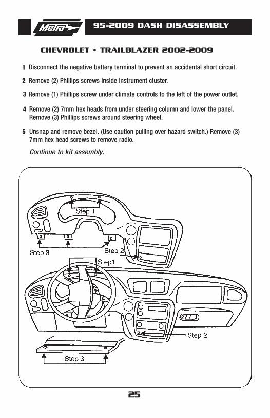
Remove (1) Phillips screw under climate controls to the left of the power outlet.
Disconnect the negative battery terminal to prevent an accidental short circuit.
3
Remove (2) Phillips screws inside instrument cluster.2
Remove (2) 7mm hex heads from under steering column and lower the panel.Remove (3) Phillips screws around steering wheel.
4
Unsnap and remove bezel. (Use caution pulling over hazard switch.) Remove (3)7mm hex head screws to remove radio.
5
Continue to kit assembly.
CHEVROLET • TRAILBLAZER 2002-2009

26
95-2009 DASH DISASSEMBLY
1
Remove (1) Phillips screw from thecigarette lighter compartment.
Disconnect the negative battery terminal to prevent an accidentalshort circuit.
3
Remove the ashtray and (1) phillipsscrew exposed in the ashtray cavity.
2
Remove (2) Phillips screws securingthe factory head unit and disconnectthe wiring.
4
CHEVROLET • VENTURE 2000OLDSMOBILE • SILHOUETTE 2000
PONTIAC • MONTANA (EXCEPT SV6) 2000
Continue to kit assembly.
27
95-2009 DASH DISASSEMBLY
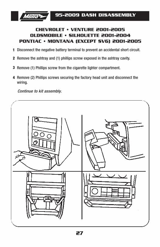
1 Disconnect the negative battery terminal to prevent an accidental short circuit.
CHEVROLET • VENTURE 2001-2005OLDSMOBILE • SILHOUETTE 2001-2004
PONTIAC • MONTANA (EXCEPT SV6) 2001-2005
Remove (1) Phillips screw from the cigarette lighter compartment. 3
Remove the ashtray and (1) phillips screw exposed in the ashtray cavity. 2
Remove (2) Phillips screws securing the factory head unit and disconnect thewiring.
4
Continue to kit assembly.
28
95-2009 DASH DISASSEMBLY
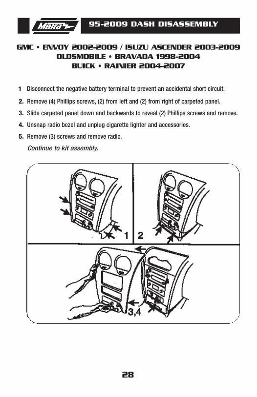
GMC • ENVOY 2002-2009 / ISUZU ASCENDER 2003-2009OLDSMOBILE • BRAVADA 1998-2004
BUICK • RAINIER 2004-2007
2. Remove (4) Phillips screws, (2) from left and (2) from right of carpeted panel.
3. Slide carpeted panel down and backwards to reveal (2) Phillips screws and remove.
4. Unsnap radio bezel and unplug cigarette lighter and accessories.
5. Remove (3) screws and remove radio.
Continue to kit assembly.
1 Disconnect the negative battery terminal to prevent an accidental short circuit.

29
95-2009 DASH DISASSEMBLY
HONDA • PASSPORT 1998-2002
ISUZU • AMIGO 1998-2000 / RODEO 1998-2004RODEO SPORT 2001-2003
1 Disconnect the negative battery terminal to prevent an accidentalshort circuit.
Remove the ashtray and (1) Phillipsscrew exposed in the ashtray cavity.Unclip and remove the trim panel surrounding the factory radio.Remove (4) Phillips screws securingthe factory radio and disconnect thewiring.
2
Continue to kit assembly.
30
95-2009 DASH DISASSEMBLY
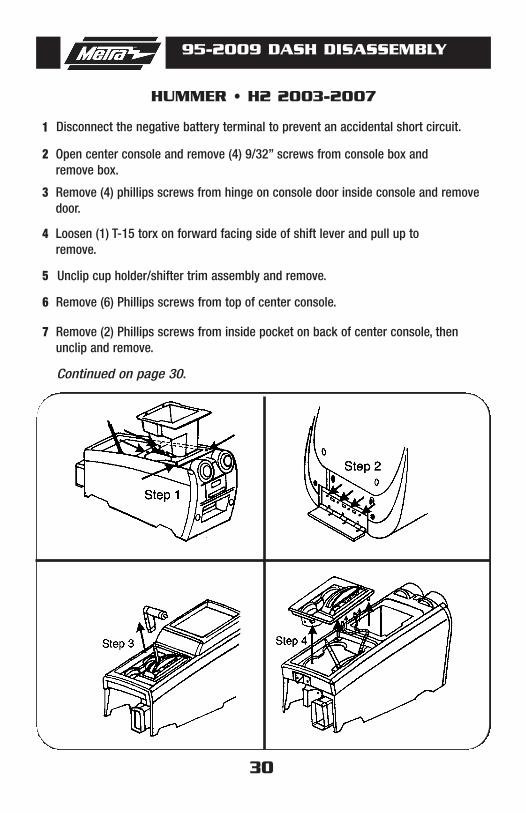
HUMMER • H2 2003-2007
1
Remove (4) phillips screws from hinge on console door inside console and removedoor.
Disconnect the negative battery terminal to prevent an accidental short circuit.
3
Open center console and remove (4) 9/32” screws from console box and remove box.
2
Loosen (1) T-15 torx on forward facing side of shift lever and pull up to remove.
4
Unclip cup holder/shifter trim assembly and remove.5
Remove (6) Phillips screws from top of center console.6
Remove (2) Phillips screws from inside pocket on back of center console, thenunclip and remove.
7
Continued on page 30.

31
95-2009 DASH DISASSEMBLY
Continue to kit assembly.
HUMMER • H2 2003-2007
8
Slide control assembly rearwards.
Remove (1) 10mm bolt to right of shift lever.
10-
Remove (2) Phillips screws from under console box on drivers side and (2) Phillips screws from under console trimtop on passenger side.
9
Remove (2) T-30 torx bolts from top of rado/climate control trim andunclip and remove.
11
Remove (3) 9/32” screws that hold the radio in.12
Continued from page 30.
32
95-2009 DASH DISASSEMBLY
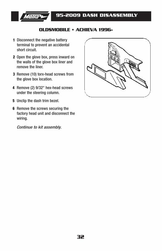
OLDSMOBILE • ACHIEVA 1996-
1
Remove (10) torx-head screws fromthe glove box location.
Disconnect the negative battery terminal to prevent an accidentalshort circuit.
3
Open the glove box, press inward onthe walls of the glove box liner andremove the liner.
2
Remove (2) 9/32" hex-head screwsunder the steering column.
4
Unclip the dash trim bezel. 5
Remove the screws securing the factory head unit and disconnect thewiring.
6
Continue to kit assembly.

33
95-2009 DASH DISASSEMBLY
OLDSMOBILE • ALERO 1999-2004
1
Unclip and remove shifter trim panel.
Disconnect the negative battery terminal to prevent an accidentalshort circuit.
3
Remove shift knob by using a smallscrewdriver to remove U-clip fromfront of shifter and pull upward.
2
Unclip and remove radio and climatecontrol panel by pulling from bottom.
4
Remove (3) 9/32" screws from radioand remove.
5
Continue to kit assembly.

34
95-2009 DASH DISASSEMBLY
OLDSMOBILE • AURORA 1995-2003
1
Remove (2) 7mm screws securing thefactory head unit and disconnect thewiring.
Disconnect the negative battery terminal to prevent an accidentalshort circuit.
3
Unclip the radio trim bezel andremove the bezel.
2
Continue to kit assembly.

35
95-2009 DASH DISASSEMBLY
OLDSMOBILE • CUTLASS 1997-1999CUTLASS SUPREME 1995-1997
1
Remove (2) ) 9/32" hex-head screwssecuring the factory head unit anddisconnect the wiring.
Disconnect the negative battery terminal to prevent an accidentalshort circuit.
3
Unclip the radio trim bezel andremove.
2
Continue to kit assembly.
36
95-2009 DASH DISASSEMBLY
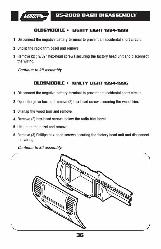
OLDSMOBILE • EIGHTY EIGHT 1994-1999
1
Remove (2) ) 9/32" hex-head screws securing the factory head unit and disconnectthe wiring.
Disconnect the negative battery terminal to prevent an accidental short circuit.
3
Unclip the radio trim bezel and remove.2
Continue to kit assembly.
1
Unsnap the wood trim and remove.
Disconnect the negative battery terminal to prevent an accidental short circuit.
3
Open the glove box and remove (2) hex-head screws securing the wood trim. 2
4
Remove (3) Phillips hex-head screws securing the factory head unit and disconnectthe wiring.
Remove (2) hex-head screws below the radio trim bezel.
6
Lift up on the bezel and remove. 5
Continue to kit assembly.
OLDSMOBILE • NINETY EIGHT 1994-1996

37
95-2009 DASH DISASSEMBLY
OLDSMOBILE • INTRIGUE 1998-2003
1
Remove the center console.
Disconnect the negative battery terminal to prevent an accidentalshort circuit.
3
Open the center console storagecompartment and remove (2) 9/32"hex-head screws exposed.
2
Unclip the radio trim bezel andremove.
4
Remove (2) 9/32" hex-head screwssecuring the factory head unit anddisconnect the wiring.
5
Continue to kit assembly.
38
95-2009 DASH DISASSEMBLY
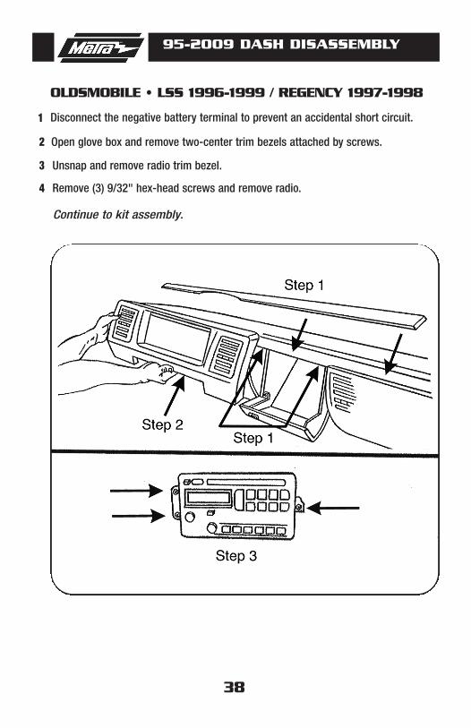
OLDSMOBILE • LSS 1996-1999 / REGENCY 1997-1998
1
Unsnap and remove radio trim bezel.
Disconnect the negative battery terminal to prevent an accidental short circuit.
3
Open glove box and remove two-center trim bezels attached by screws.2
Remove (3) 9/32" hex-head screws and remove radio.4
Continue to kit assembly.

39
95-2009 DASH DISASSEMBLY
PONTIAC • AZTEC 2001-2005
1
Remove (1) Phillips screw exposedinside bottom cup holder.
Disconnect the negative battery terminal to prevent an accidentalshort circuit.
3
Pull out cup holder inserts.2
Unsnap and remove shifter trim withcup holders.
4
Remove (2) #15 torx at bottom ofradio/climate bezel.
5
Continue to kit assembly.
40
95-2009 DASH DISASSEMBLY
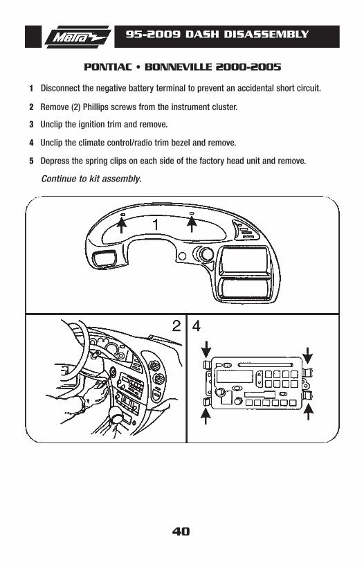
PONTIAC • BONNEVILLE 2000-2005
1
Unclip the ignition trim and remove.
Disconnect the negative battery terminal to prevent an accidental short circuit.
3
Remove (2) Phillips screws from the instrument cluster. 2
Unclip the climate control/radio trim bezel and remove. 4
Depress the spring clips on each side of the factory head unit and remove.5
Continue to kit assembly.

41
95-2009 DASH DISASSEMBLY
PONTIAC • GRAND AM 2001-2005
1 Disconnect the negative battery terminal to prevent an accidentalshort circuit.
Unsnap and remove radio trim bezel.2
Remove (3) 9/32” screws from radiobrackets and remove radio.
3
Continue to kit assembly.
42
95-2009 DASH DISASSEMBLY
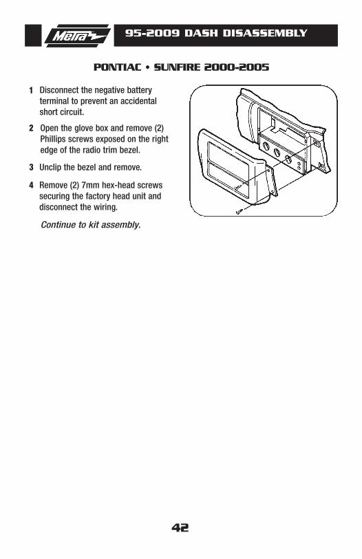
PONTIAC • SUNFIRE 2000-2005
1 Disconnect the negative battery terminal to prevent an accidentalshort circuit.
Open the glove box and remove (2)Phillips screws exposed on the rightedge of the radio trim bezel.
2
Unclip the bezel and remove. 3
Remove (2) 7mm hex-head screwssecuring the factory head unit anddisconnect the wiring.
4
Continue to kit assembly.

43
95-2009 DASH DISASSEMBLY
TOYOTA • MATRIX 2003-2004PONTIAC • VIBE 2003-2008
SCAN
SEEKTRACK
TUNE
AM FM1 FM2 DISK
1 Disconnect the negative battery terminal to prevent an accidentalshort circuit.
Unclip the bottom edge of the radiotrim panel then lift up and out toremove. (Figure A)
2
Remove (4) 10MM bolts securing thefactory radio. (Figure B)
3
Continue to kit assembly.
A
B

44
95-2009 DASH DISASSEMBLY
SUZUKI • AERIO 2002
1 Disconnect the negative battery terminal to prevent an accidentalshort circuit.
Unclip the dash trim bezel and remove. 2
Remove (4) Phillips screws securingthe factory head unit and disconnectthe wiring.
3
Continue to kit assembly.
45
95-2009 DASH DISASSEMBLY
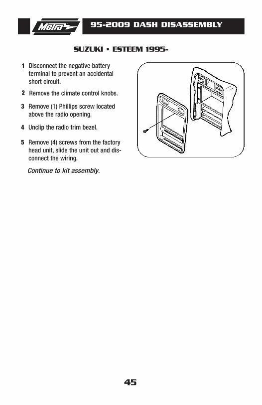
SUZUKI • ESTEEM 1995-
1 Disconnect the negative battery terminal to prevent an accidentalshort circuit.
Remove the climate control knobs. 2
Remove (1) Phillips screw locatedabove the radio opening.
3
Unclip the radio trim bezel. 4
Remove (4) screws from the factoryhead unit, slide the unit out and dis-connect the wiring.
5
Continue to kit assembly.

46
95-2009 TAB INSTRUCTIONS
CHEVY/GM/METRO/SUZUKICADILLAC-FLEETWOOD/BROUGHAM
*Note: Refer also to the instructions included with the aftermarket radio.
GM vehicles.Cut tabs highlighted on both sides ofboth brackets. (Figure A)
1
CHEVY Tracker/METRO/SUZUKI.Cut tabs highlighted on both sides ofboth brackets. (Figure B)
2
CADILLAC Fleetwood/Broughham.Cut all tabs highlighted on both sidesof both brackets. (Figure C)
3
Continued on page 46.
A
B
C

47
95-2009 TAB INSTRUCTIONS
ISUZU-PONTIAC/TOYOTA/CADILLAC-ELDORADO/SEVILLE
ISUZU Amigo/Rodeo/Rodeo Sport.Cut tabs highlighted. (Figure D)
4
TOYOTA Matrix/PONTIAC Vibe.Cut tabs highlighted. (Figure E)Cut (4) tabs highlighted on double DIN trim plate. (Figure H)
5
CADILLAC Eldorado/Seville.Cut tabs highlighted on double DINbrackets. (Figure F)Cut (1) tab highlighted on top left cornerof double DIN trim plate. (Figure G)
6
Continue to final assembly.
Continued from page 46.
*Note: Refer also to the instructions included with the aftermarket radio.
D
E
F
G
H
48
95-2009 KIT ASSEMBLY
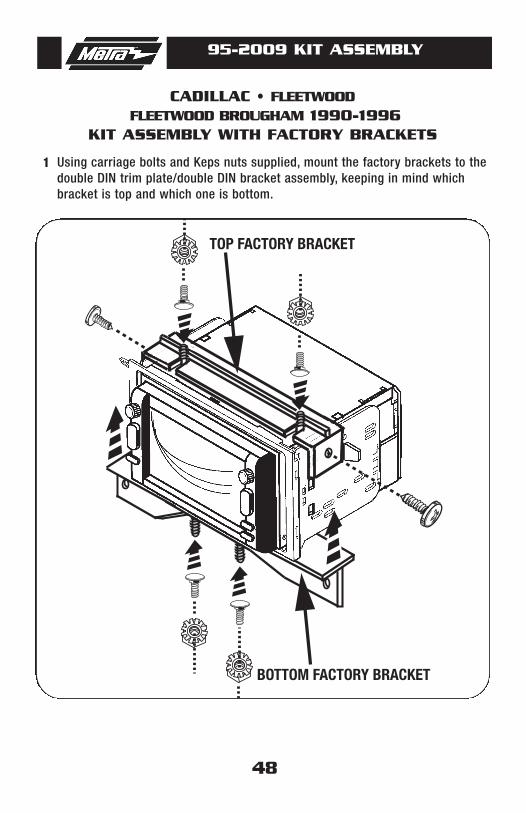
TOP FACTORY BRACKET
BOTTOM FACTORY BRACKET
1 Using carriage bolts and Keps nuts supplied, mount the factory brackets to thedouble DIN trim plate/double DIN bracket assembly, keeping in mind whichbracket is top and which one is bottom.
CADILLAC • FLEETWOODFLEETWOOD BROUGHAM 1990-1996
KIT ASSEMBLY WITH FACTORY BRACKETS

49
95-2009 KIT ASSEMBLY
1
1 Disconnect the negative battery terminal to prevent an accidental short circuit.
Align the tabs on the bottom of the double DIN trim plate with notches in sub dash.2
Secure with the (2) Carriage bolts and (2) Kep nuts provided.3
CADILLAC • ELDORADO 1992-1995SEVILLE 1992-1995
Continue to kit assembly.

50
95-2009 KIT ASSEMBLY
DOUBLE DIN RADIO PROVISIONSTACKED ISO MOUNT UNIT(S) PROVISION
Snap the Double DIN brackets to theedge of the Double DIN trim plate. (Figure A)
1
Slide the Double DIN head unit orstacked ISO head units into the brack-et/radio housing assembly and securethe Double DIN head unit or stackedISO head units to the assembly usingthe screws supplied with the radio.(Figure B)
2
Note: For the Buick Le Sabre,Oldsmobile Aurora and the PontiacBonneville the (3) speed clips andscrews provided with the kit will needto be installed into the sub dash wherethe screw holes line up on the kit.
Continue to final assembly.
*Note: Refer also to the instructions included with the aftermarket radio.
A
B
95-2009 FINAL ASSEMBLY
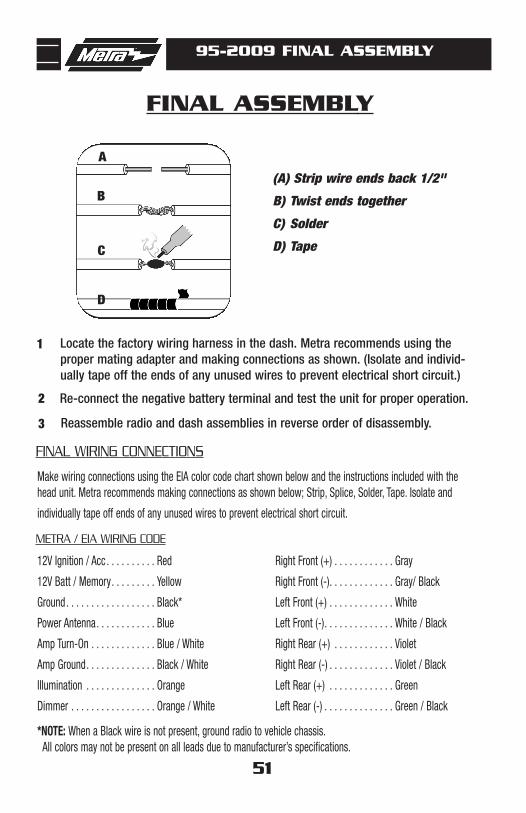
FINAL ASSEMBLY
(A) Strip wire ends back 1/2"
B) Twist ends together
C) Solder
D) Tape
A
B
C
D
Locate the factory wiring harness in the dash. Metra recommends using the proper mating adapter and making connections as shown. (Isolate and individ-ually tape off the ends of any unused wires to prevent electrical short circuit.)
Re-connect the negative battery terminal and test the unit for proper operation.
Reassemble radio and dash assemblies in reverse order of disassembly.
1
2
3
FINAL WIRING CONNECTIONS
Make wiring connections using the EIA color code chart shown below and the instructions included with thehead unit. Metra recommends making connections as shown below; Strip, Splice, Solder, Tape. Isolate and
individually tape off ends of any unused wires to prevent electrical short circuit.
METRA / EIA WIRING CODE
12V Ignition / Acc . . . . . . . . . . Red
12V Batt / Memory. . . . . . . . . Yellow
Ground. . . . . . . . . . . . . . . . . . Black*
Power Antenna. . . . . . . . . . . . Blue
Amp Turn-On . . . . . . . . . . . . . Blue / White
Amp Ground. . . . . . . . . . . . . . Black / White
Illumination . . . . . . . . . . . . . . Orange
Dimmer . . . . . . . . . . . . . . . . . Orange / White
Right Front (+) . . . . . . . . . . . . Gray
Right Front (-). . . . . . . . . . . . . Gray/ Black
Left Front (+) . . . . . . . . . . . . . White
Left Front (-). . . . . . . . . . . . . . White / Black
Right Rear (+) . . . . . . . . . . . . Violet
Right Rear (-) . . . . . . . . . . . . . Violet / Black
Left Rear (+) . . . . . . . . . . . . . Green
Left Rear (-) . . . . . . . . . . . . . . Green / Black
*NOTE: When a Black wire is not present, ground radio to vehicle chassis.All colors may not be present on all leads due to manufacturer’s specifications.
51

95-2009 INSTRUCTIONS
1-800-221-0932 REV. 04/15/09 © COPYRIGHT 2004-2009 METRA ELECTRONICS CORPORATION INST95-2009
www.metraonline.com