9000 series rack products -...
TRANSCRIPT

Compaq Confidential – Need to Know RequiredWriter: AmyL. Laffitte Project: Compaq 9000 Series Rack Products Reference Guide Comments:
Part Number: 142553-003 File Name: a-frnt.doc Last Saved On: 6/26/01 2:14 PM
9000 Series Rack ProductsReference Guide
Third Edition (July 2001)Part Number 142553-003Compaq Computer Corporation

Compaq Confidential – Need to Know RequiredWriter: AmyL. Laffitte Project: Compaq 9000 Series Rack Products Reference Guide Comments:
Part Number: 142553-003 File Name: a-frnt.doc Last Saved On: 6/26/01 2:14 PM
Notice© 2001 Compaq Computer Corporation
Compaq, the Compaq logo, and ProLiant are Registered United States Patent and Trademark Office. Allother product names mentioned herein may be trademarks of their respective companies.
Microsoft, MS-DOS, Windows, and Windows NT are trademarks of Microsoft Corporation in theUnited States and other countries.
All other product names mentioned herein may be trademarks of their respective companies.
Compaq service tool software, including associated documentation, is the property of and containsconfidential technology of Compaq Computer Corporation. Service customer is hereby licensed to usethe software only for activities directly relating to the delivery of, and only during the term of, theapplicable services delivered by Compaq or its authorized service provider. Customer may not modifyor reverse engineer, remove, or transfer the software or make the software or any resultant diagnosis orsystem management data available to other parties without Compaq’s or its service provider’s consent.Upon termination of the services, customer will, at Compaq’s or its service provider’s option, destroy orreturn the software and associated documentation in its possession.
Compaq shall not be liable for technical or editorial errors or omissions contained herein. Theinformation in this document is provided “as is” without warranty of any kind and is subject to changewithout notice. The warranties for Compaq products are set forth in the express limited warrantystatements accompanying such products. Nothing herein should be construed as constituting anadditional warranty.
Compaq 9000 Series Rack Products Reference GuideThird Edition (July 2001)Part Number 142553-003

Compaq Confidential – Need to Know RequiredWriter: AmyL. Laffitte Project: Compaq 9000 Series Rack Products Reference Guide Comments:
Part Number: 142553-003 File Name: a-frnt.doc Last Saved On: 6/26/01 2:14 PM
Contents
About This GuideText Conventions.......................................................................................................viiSymbols in Text....................................................................................................... viiiSymbols on Equipment............................................................................................ viiiRack Stability .............................................................................................................ixGetting Help ...............................................................................................................ix
Compaq Technical Support ..................................................................................xCompaq Website...................................................................................................xCompaq Authorized Reseller...............................................................................xi
Chapter 1Overview
Compaq 9000 Rack Series....................................................................................... 1-2Rack Option Accessory Kits.................................................................................... 1-3Delivery Considerations .......................................................................................... 1-4Installation Sequence ............................................................................................... 1-5
Installation Service ........................................................................................... 1-6
Chapter 2Configuration Factors
Rack Configuration Software .................................................................................. 2-1Component Placement ............................................................................................. 2-3Additional Considerations ....................................................................................... 2-3Optimum Environment ............................................................................................ 2-5
Space Requirements ......................................................................................... 2-5Power Requirements......................................................................................... 2-5Grounding Requirements.................................................................................. 2-6Temperature Requirements............................................................................... 2-7Airflow Requirements ...................................................................................... 2-8

iv Compaq 9000 Series Rack Products Reference Guide
Compaq Confidential – Need to Know RequiredWriter: AmyL. Laffitte Project: Compaq 9000 Series Rack Products Reference Guide Comments:
Part Number: 142553-003 File Name: a-frnt.doc Last Saved On: 6/26/01 2:14 PM
Chapter 3Preparing the Rack for Component Installation
Required Tools......................................................................................................... 3-2Checking the Hardware............................................................................................ 3-2Stabilizing the Rack ................................................................................................. 3-3
Standalone Racks.............................................................................................. 3-3Multiple Racks.................................................................................................. 3-5
Server/Storage vs. Switching Configurations (Model 9842) ................................... 3-5Completing the Rack Setup for Component Installation.......................................... 3-6
Opening the Rack Door .................................................................................... 3-6Removing the Rack Door.................................................................................. 3-7Removing the Sidewall Panels.......................................................................... 3-8
Chapter 4Installing Components into the Rack
Overview.................................................................................................................. 4-1General Guidelines ........................................................................................... 4-2
Installation Sequence ............................................................................................... 4-3Using the Template .................................................................................................. 4-4Inserting the Cage Nuts............................................................................................ 4-5Installing the Rails ................................................................................................... 4-6
Installing the Adjustable Fixed Rail.................................................................. 4-6Installing the Sliding Rail ................................................................................. 4-9Attaching the Sliding Bracket Rails................................................................ 4-12
Preparing the Component Chassis ......................................................................... 4-14Adjustable Fixed Rails.................................................................................... 4-14Cable Management Arm Bracket.................................................................... 4-15
Installing the Component into the Rack................................................................. 4-16Inserting the Component into the Rack........................................................... 4-17Attaching the Cable Management Arm .......................................................... 4-18Attaching the Cables ....................................................................................... 4-19Removing the Cable Access Panel.................................................................. 4-20Routing the Cables for Server/Storage Applications ...................................... 4-21Routing the Cables for Switching Applications.............................................. 4-23
Attaching Power Cables......................................................................................... 4-24
Chapter 5Options
Rack Considerations ................................................................................................ 5-2Compaq 1U Keyboard Drawer Option Kit .............................................................. 5-3
Kit Contents ...................................................................................................... 5-3Additional Hardware......................................................................................... 5-3Tool Required ................................................................................................... 5-3

About This Guide v
Compaq Confidential – Need to Know RequiredWriter: AmyL. Laffitte Project: Compaq 9000 Series Rack Products Reference Guide Comments:
Part Number: 142553-003 File Name: a-frnt.doc Last Saved On: 6/26/01 2:14 PM
Optionscontinued
Compaq 25-inch Rail Adapter Option Kit ............................................................... 5-4Kit Contents...................................................................................................... 5-4Tool Required................................................................................................... 5-4
Compaq Ballast Rack Option Kit ............................................................................ 5-5Kit Contents...................................................................................................... 5-5Tool Required................................................................................................... 5-5
Compaq Blanking Panels Rack Option Kit.............................................................. 5-6Kits Available ................................................................................................... 5-6Additional Hardware ........................................................................................ 5-6Tool Required................................................................................................... 5-6
Compaq Cable Management Bracket Rack Option Kit ........................................... 5-7Kit Contents...................................................................................................... 5-7Additional Hardware ........................................................................................ 5-7Tool Required................................................................................................... 5-7
Compaq Rack Option Baying Kit ............................................................................ 5-8Kit Contents...................................................................................................... 5-8Tool Required................................................................................................... 5-8
Compaq 9000 Rack Series Extension Option Kit .................................................... 5-9Kit Contents...................................................................................................... 5-9Additional Hardware ........................................................................................ 5-9Tool Required................................................................................................... 5-9
Compaq Fan (110V/220V) Option Kit .................................................................. 5-10Kit Contents.................................................................................................... 5-10Tool Required................................................................................................. 5-10
Compaq Ground Bonding Option Kit.................................................................... 5-11Kit Contents.................................................................................................... 5-11Additional Hardware ...................................................................................... 5-11
Compaq 9000 Series Rack Short Rear Door Option Kit........................................ 5-12Kit Contents.................................................................................................... 5-12
Compaq Side Panels Option Kit ............................................................................ 5-12Kit Contents.................................................................................................... 5-12

vi Compaq 9000 Series Rack Products Reference Guide
Compaq Confidential – Need to Know RequiredWriter: AmyL. Laffitte Project: Compaq 9000 Series Rack Products Reference Guide Comments:
Part Number: 142553-003 File Name: a-frnt.doc Last Saved On: 6/26/01 2:14 PM
Optionscontinued
Compaq 9000 Series Rack Stabilizer Option Kit ................................................... 5-13Kit Contents .................................................................................................... 5-13Additional Hardware....................................................................................... 5-13
Appendix AElectrostatic Discharge
Grounding Methods ................................................................................................ A-2
Appendix BTransportation Instructions
Transportation Methods ...........................................................................................B-1Air Transport.....................................................................................................B-2Land Transport..................................................................................................B-2Sea Transport ....................................................................................................B-2
Delivery Services .....................................................................................................B-3Inside Rack Delivery Service............................................................................B-3Expedited Rack Delivery Service .....................................................................B-4Shipping/Delivery Considerations ....................................................................B-4
Appendix CSpecifications
Model 9122 ..............................................................................................................C-1Model 9136 ..............................................................................................................C-2Model 9142 ..............................................................................................................C-2Model 9842 ..............................................................................................................C-3
Index

About This Guide vii
Compaq Confidential – Need to Know RequiredWriter: AmyL. Laffitte Project: Compaq 9000 Series Rack Products Reference Guide Comments:
Part Number: 142553-003 File Name: a-frnt.doc Last Saved On: 6/26/01 2:14 PM
About This Guide
This guide provides instructions for installation and configuration of aCompaq 9000 Series rack and associated options.
Text ConventionsThis document uses the following conventions to distinguish elements of text:
Keys Keys are shown in boldface. A plus sign (+)between two keys indicates that they should bepressed simultaneously.
USER INPUT User input is shown in a different typeface and inuppercase.
FILENAMES File names are shown in uppercase italics.
Menu Options,Command Names,Dialog Box Names
These elements are shown in initial capital letters.
COMMANDS,DIRECTORY NAMES,and DRIVE NAMES
These elements appear in uppercase.
Type When you are instructed to type information, typethe information without pressing the Enter key.
Enter When you are instructed to enter information, typethe information and then press the Enter key.

viii Compaq 9000 Series Rack Products Reference Guide
Compaq Confidential – Need to Know RequiredWriter: AmyL. Laffitte Project: Compaq 9000 Series Rack Products Reference Guide Comments:
Part Number: 142553-003 File Name: a-frnt.doc Last Saved On: 6/26/01 2:14 PM
Symbols in TextCertain symbols are used throughout this guide to draw attention to importantinformation.
WARNING: Text set off in this manner indicates that failure to follow directions
in the warning could result in bodily harm or loss of life.
CAUTION: Text set off in this manner indicates that failure to follow directions
could result in damage to equipment or loss of information.
IMPORTANT: Text set off in this manner presents clarifying information or specific
instructions.
NOTE: Text set off in this manner presents commentary, sidelights, or interesting points
of information.
Symbols on EquipmentThe following symbols are used on equipment to draw attention to potentiallyhazardous parts.
Any surface or area of the equipment marked with these symbols
indicates the presence of electrical shock hazards. Enclosed area
contains no operator serviceable parts.
WARNING: To reduce the risk of injury from electrical shock hazards,
do not open this enclosure.
Any RJ-45 receptacle marked with these symbols indicates a Network
Interface Connection.
WARNING: To reduce the risk of electrical shock, fire, or damage to
the equipment, do not plug telephone or telecommunications
connectors into this receptacle.

About This Guide ix
Compaq Confidential – Need to Know RequiredWriter: AmyL. Laffitte Project: Compaq 9000 Series Rack Products Reference Guide Comments:
Part Number: 142553-003 File Name: a-frnt.doc Last Saved On: 6/26/01 2:14 PM
Any surface or area of the equipment marked with these symbols
indicates the presence of a hot surface or hot component. If this
surface is contacted, the potential for injury exists.
WARNING: To reduce the risk of injury from a hot component, allow
the surface to cool before touching.
Power Supplies or Systems marked with these symbols
indicate the equipment is supplied by multiple sources of
power.
WARNING: To reduce the risk of injury from electrical shock,
remove all power cords to completely disconnect power from
the system.
Rack Stability
WARNING: To reduce the risk of personal injury or damage to the equipment be
sure that:
� The leveling jacks are extended to the floor.
� The full weight of the rack rests on the leveling jacks.
� In single-rack installations (standalone racks), stabilizing feet areattached to the rack.
� In multiple-rack installations, the racks are coupled.
� No more than one component is extended at a time. Otherwise, the rackis likely to become unbalanced and tip over.
Getting HelpIf you have a problem and have exhausted the information in this guide, youcan get further information and other help in the following locations.

x Compaq 9000 Series Rack Products Reference Guide
Compaq Confidential – Need to Know RequiredWriter: AmyL. Laffitte Project: Compaq 9000 Series Rack Products Reference Guide Comments:
Part Number: 142553-003 File Name: a-frnt.doc Last Saved On: 6/26/01 2:14 PM
Compaq Technical Support
You are entitled to free hardware technical telephone support for your productfor as long you own the product. A technical support specialist will help youdiagnose the problem or guide you to the next step in the warranty process.
In North America, call the Compaq Technical Phone Support Center at1-800-OK-COMPAQ1. This service is available 24 hours a day, 7 days a week.
Outside North America, call the nearest Compaq Technical Support PhoneCenter. The most current telephone numbers for worldwide Technical SupportCenters are listed on the Compaq website.
Be sure to have the following information available before you call Compaq:
� Technical support registration number (if applicable)
� Product serial number (s)
� Product model name(s) and numbers(s)
� Add-on boards or hardware
� Third-party hardware or software
� Operating system type and revision level
� Detailed, specific questions
Compaq Website
The Compaq website has information on this product as well as the latestdrivers and Flash ROM images. You can access the Compaq website:
www.compaq.com
1 For continuous quality improvement, calls may be recorded or monitored.

About This Guide xi
Compaq Confidential – Need to Know RequiredWriter: AmyL. Laffitte Project: Compaq 9000 Series Rack Products Reference Guide Comments:
Part Number: 142553-003 File Name: a-frnt.doc Last Saved On: 6/26/01 2:14 PM
Compaq Authorized Reseller
For the name of your nearest Compaq authorized reseller:
� In the United States, call 1-800-345-1518.
� In Canada, call 1-800-263-5868.
� Elsewhere, see the Compaq website for locations and telephonenumbers.

Compaq Confidential – Need to Know RequiredWriter: Amy L. Laffitte Project: Compaq 9000 Series Rack Products Reference Guide Comments: FINAL
Part Number: 142553-003 File Name: b-ch1.doc Last Saved On: 6/26/01 12:56 PM
Chapter 1Overview
As computer systems have evolved in size and complexity, managing them hasbecome a critical concern. By centralizing your equipment, the efficiency andaccessibility of your system can be increased dramatically. Usingrack-mountable products allows you to decrease the footprint required tohouse your existing hardware while still providing expansion capability.

1-2 Compaq 9000 Series Rack Products Reference Guide
Compaq Confidential – Need to Know RequiredWriter: Amy L. Laffitte Project: Compaq 9000 Series Rack Products Reference Guide Comments: FINAL
Part Number: 142553-003 File Name: b-ch1.doc Last Saved On: 6/26/01 12:56 PM
Compaq 9000 Rack SeriesThe Compaq 9000 Series of racks consists of four models—9122, 9136, 9142,and 9842. Models 9122, 9136, and 9142 are opal in color, with a perforatedfront and back door, and optional solid side panels. Model 9842 is also opal incolor, with perforated interchangeable front and rear split doors, cable accesspanel, and optional solid side panels.
All Compaq rack-mountable products are designed to fit our industry-standard19-inch wide rails. Appendix C gives detailed specifications of each model.
Figure 1-1. 9000 Series racks

Overview 1-3
Compaq Confidential – Need to Know RequiredWriter: Amy L. Laffitte Project: Compaq 9000 Series Rack Products Reference Guide Comments: FINAL
Part Number: 142553-003 File Name: b-ch1.doc Last Saved On: 6/26/01 12:56 PM
Rack Option Accessory KitsIn addition to the standard racks, Compaq also provides optional accessory kitsto complement or complete your rack solution. The following list is only asampling of the many Compaq rack options available. For further information,visit
www.compaq.com/racks
� Side Panel Option Kit—Enclosures for the sides of a rack.
� 9000 Series Rack Stabilizer Option Kit—Essential to increase stabilityof free standing racks, or use of modified side feet.
NOTE: Install Stabilizing Feet prior to other components.
� Standard Feet—For free-standing racks.
� Modified Side Feet—Allows 9000 Series racks to be stabilized fromthe front, when placed between other same-size racks and non-9000Series racks.
� Ballast Rack Option Kit—Used with the Stabilizing Feet to provideadditional rack stability when very heavy equipment is routinelyinstalled, removed, or accessed within the rack.
� Rack Option Baying Kit—Joins two or more racks together.
� Fan (110V/220V) Rack Option Kit—Enhances natural convectioncooling by increasing the airflow in the rack and pulling hot air out ofthe top of the rack.
� Ground Bonding Option Kit— Reduces the electromagnetic emissionsthat may be given off by electronic components operating within therack cabinet.
� Monitor/Utility Shelf Kit—A 1U fixed, ventilated shelf that holds amonitor or other rack component (bezels for 15-inch (38 cm) and17-inch (43.2 cm) monitors are included).
� Keyboard Drawer Kit—A 1U drawer that holds a concealed keyboard.
� Sliding Shelf Kit—Allows easy access to various rack components.
� Depth Adjustable Fixed Rail Kit—Provides rails that can be adjusted tovarious depths.
� Flat Panel Monitor Rackmount—A 2U Rackmount TFT Flat Panelmonitor.

1-4 Compaq 9000 Series Rack Products Reference Guide
Compaq Confidential – Need to Know RequiredWriter: Amy L. Laffitte Project: Compaq 9000 Series Rack Products Reference Guide Comments: FINAL
Part Number: 142553-003 File Name: b-ch1.doc Last Saved On: 6/26/01 12:56 PM
� Server Console Switch—A programmable switch panel and theconnection hardware used to switch a keyboard, a monitor, and a mouseamong multiple servers.
� Blanking Panels Option Kit—Used to fill gaps between components,which can cause changes in the airflow, adversely affecting coolingwithin the rack when the front of the rack is not completely filled.
� Networking Cable and Recessed Rail Management Kits—Used to routeand organize cables within the rack.
� Cable Management Bracket Rack Option Kit— Designed for use withall 9000 Series racks to help with cable management.
� 25-inch Rail Adapter Option Kit— Allows the inner rails on Compaq9000 Series racks to accommodate third-party rack options. Adaptersmay be stacked for requirements greater than 2U.
� Extension Option Kit— Adds 3.5 inches (8.9 cm) of depth to the rear ofthe rack.
� Shock Pallet Spares Kit— Used to transport a configured rack.
Compaq also offers several rack-mountable power products. For morecomplete information see the Compaq website:
www.compaq.com/ups
Contact your nearest Compaq authorized reseller or service provider forinformation about ordering any of these Compaq options. For the name ofyour nearest Compaq authorized reseller, see the “About This Guide” sectionof this manual.
Delivery ConsiderationsWhen preparing to receive palletized Compaq racks, consider the following:
� The dock door at the receiving site has to accommodate the height andwidth of palletized racks.
� Do not lay a rack on its side, because the sheet metal can wrench anddistort.
� Transport a rack as far into the building as possible while it is still on thepallet. Ideally, move the palletized rack into its final destination beforeremoving the rack from the pallet, or removing any of the packaging.

Overview 1-5
Compaq Confidential – Need to Know RequiredWriter: Amy L. Laffitte Project: Compaq 9000 Series Rack Products Reference Guide Comments: FINAL
Part Number: 142553-003 File Name: b-ch1.doc Last Saved On: 6/26/01 12:56 PM
Installation SequenceFollowing is the recommended sequence of events for the most efficientinstallation of your Compaq rack and components:
1. Install the Rack Builder Online software via the Compaq website.Using Rack Builder Online, plan the rack component location andinstallation sequence.
2. Select a location to unpack and set up your rack. This should be as closeas possible to the permanent site for your rack. See Chapter 2 for theamount of room space needed to unpack and build the rack.
3. Watch the Rack Installation Video (on CD) that came with your rack.
4. Remove the packaging from the rack and verify the hardware contents.
5. Stabilize the rack.
NOTE: Install Stabilizing Feet prior to other components.
6. Join two or more racks together using the Rack Option Baying Kit.
7. Remove any doors and panels from the rack as appropriate to providenecessary access for component installation.
8. Compaq recommends first installing products, such as PowerDistribution Units (PDU) or switchboxes, in sidewall locations and theninstalling products, such as Uninterruptible Power System (UPS), fromthe bottom.
9. Install the appropriate support rails and/or tray for the firstrack-mountable component.
10. Install the individual components.
11. Connect any appropriate cables to the component.
12. Attach a cable management arm, if required.
13. Install the remaining components in the appropriate sequence.
14. Complete any cabling attachments or adjustments.
15. Reinstall any doors and panels, including any blanking panels.
16. Power up and configure the system.

1-6 Compaq 9000 Series Rack Products Reference Guide
Compaq Confidential – Need to Know RequiredWriter: Amy L. Laffitte Project: Compaq 9000 Series Rack Products Reference Guide Comments: FINAL
Part Number: 142553-003 File Name: b-ch1.doc Last Saved On: 6/26/01 12:56 PM
Installation Service
In the Unites States, Compaq can make arrangements to have your rack systeminstalled by qualified guaranteed service providers. This installation servicecovers the entire hardware installation sequence, from unpacking thecomponents to routing cabling and running a test of the system.
Installation can also be provided directly by Compaq authorized serviceproviders. See “Getting Help” in the “About This Guide” section of thismanual for more information on Compaq support.

Compaq Confidential – Need to Know RequiredWriter: Amy L. Laffitte Project: Compaq 9000 Series Rack Products Reference Guide Comments: FINAL
Part Number: 142553-003 File Name: c-ch2.doc Last Saved On: 6/26/01 12:56 PM
Chapter 2Configuration Factors
Before populating your new rack, it is important to plan the placement of eachcomponent. Factors of each component, such as weight, accessibility, power,temperature, and airflow requirements, affect installation order and componentplacement in the rack.
Rack Configuration SoftwareTo help you plan your rack configuration more efficiently, Compaq providesthe browser-based tool, Rack Builder Online. The latest version is available at
www.compaq.com/racks
Rack Builder Online has two modes of operation:
� Help Me Build It Mode—includes a simple interview session to helpdetermine your rack and rack component needs. Once selections aremade, the application adds the necessary power products and rackassembly devices, such as tower-to-rack conversion kits, to complete thefinal rack assembly.
� Let Me Build It Mode—lets you select the individual devices that arerequired for your configuration.

2-2 Compaq 9000 Series Rack Products Reference Guide
Compaq Confidential – Need to Know RequiredWriter: Amy L. Laffitte Project: Compaq 9000 Series Rack Products Reference Guide Comments: FINAL
Part Number: 142553-003 File Name: c-ch2.doc Last Saved On: 6/26/01 12:56 PM
Features of the Compaq rack configuration software include:
� Multiple Rack Configuration—allows for a number of racks to beconfigured in one session. Up to six racks can be viewed and configuredon-screen at one time.
� Graphics—graphical representations of the systems are used to visuallyrepresent the “U” height that each component occupies, and are not truegraphical representations of the products/systems.
� Labeling—allows the capability to label individual racks andcomponents within a rack to aid in rack maintenance and configuration.
� Drag & Drop—graphics of devices in a multiple-rack configuration canbe “dragged and dropped” between racks.
� Reports—new reports have been added to provide rack configurationlabeling and rack suite graphics for configurations that includemultiple-racks. All reports can be previewed and saved as .doc or .rtffiles.
� Third-Party Support—you can define and add third-party products.
If you are planning a new rack, use Rack Builder Online to view your rack asyou build it. Then print out a report and use it as your shopping list. Once yourrack configuration is in place, use Rack Builder Online to assist inmaintenance and upgrades.
See the documentation accompanying the software utilities for installation anduse of the software programs.

Configuration Factors 2-3
Compaq Confidential – Need to Know RequiredWriter: Amy L. Laffitte Project: Compaq 9000 Series Rack Products Reference Guide Comments: FINAL
Part Number: 142553-003 File Name: c-ch2.doc Last Saved On: 6/26/01 12:56 PM
Component PlacementThe following rules apply to the physical placement of components in therack:
� Weight—Sort all components by weight, placing the heaviestcomponents at the bottom of the rack.
� Server Console Switch—Position the switchbox above the keyboard, ormount the switchbox behind the keyboard or on the side of the rack.
� Monitor—When using a CRT monitor with this series of racks, positionthe monitor topmost within the rack.
If you are using an optional rack-mountable flat panel monitor, select aposition to accommodate the desired viewing height (a minimum of4 “U”s above the keyboard tray).
� Balance—When connecting racks, be sure to balance the weight loadbetween racks, placing the heaviest components at the bottom. Forexample, if you have several UPS units and several servers, do not putall of the UPS units into one rack. Distribute them evenly in the bottompositions of each rack.
Additional ConsiderationsFollowing are additional items to consider, based on your specific rackconfiguration:
� Power—If an Uninterruptible Power System (UPS) is installed, do notexceed its output rating. Be sure to review the installation instructionsprovided with each component for important cautions and warnings.
� PDUs—Install PDUs before installing other components.
� Height—The height of the rack and of rack-mountable components ismeasured in U increments (1U = 1.75 inches). When you areconfiguring your rack installation, remember that the total Umeasurement of the components you want to install cannot exceed thestated U height of the rack.
� Keyboard—The rack keyboard requires prior installation of a 1UKeyboard Drawer Rack Option Kit.

2-4 Compaq 9000 Series Rack Products Reference Guide
Compaq Confidential – Need to Know RequiredWriter: Amy L. Laffitte Project: Compaq 9000 Series Rack Products Reference Guide Comments: FINAL
Part Number: 142553-003 File Name: c-ch2.doc Last Saved On: 6/26/01 12:56 PM
� Monitor—The monitor requires installation of a Monitor/Utility ShelfRack Option Kit unless you are using a Flat Panel Monitor RackmountOption Kit.
� Server Console Switch—If a switchbox is configured, use theCPU-to-Switch cable included with the server. The standard distancebetween the switchbox and the keyboard, monitor, and/or mouse canvary by 3-foot (91.4-cm), 6-foot (183-cm), 12-foot (366-cm), 20-foot(610-cm) and 40-foot (1219-cm) lengths. Optional Plenum-rated KVMcables are available in 20-foot (610-cm) and 40-foot (1219-cm) lengths.
NOTE: National Electrical Regulations governing the installation of building wiring requirethat an appropriate cable, meeting fire-safety standards, be used any time cabling isrouted:
� through an overhead drop-ceiling.
� under a computer room’s raised flooring.
� from room to room.
� from floor to floor.
Be sure that the cable jacket, or sleeving, is made of material that does not burn easilyand does not exude toxic fumes when exposed to heat. Be sure that the cable you haveselected is appropriate for your installation site. If you require United States Plenum-Rated(CL2P) cable, please contact your local Compaq authorized reseller to obtain the followingoptions:
� 149363-B21—20-foot (610-cm) plenum cable
� 149364-B21—40-foot (1219-cm) plenum cable
� Rack Option Baying Kits—The number of baying kits needed to join aseries of racks is one less than the number of racks in the suite. Eachbaying kit supplies parts to bay two cabinets on 24 inches (600 mm)center line spacing.
� Side Panels—Only one set of sidewall panels is required for each rowof bayed racks.
� Stabilizing Feet—A stand-alone rack requires stabilizing feet.

Configuration Factors 2-5
Compaq Confidential – Need to Know RequiredWriter: Amy L. Laffitte Project: Compaq 9000 Series Rack Products Reference Guide Comments: FINAL
Part Number: 142553-003 File Name: c-ch2.doc Last Saved On: 6/26/01 12:56 PM
Optimum EnvironmentSpecific requirements for space, power, temperature, and airflow must be metto provide optimum performance with minimum maintenance for your rackenvironment.
Space Requirements
Consider the following spatial needs when deciding where to place your rack:
� At least 4 feet (10 cm) of clearance is needed all the way around thepallet and above the rack to remove the packing materials.
� At least 34 inches (86.4 cm) of clearance is needed in front of the rack toallow the door to open all the way.
� At least 30 inches (75 cm) of clearance is needed in the rear of the rackto provide access to components.
� At least 15 inches (38 cm) of clearance is needed around a power supplyfor servicing.
Power Requirements
WARNING: To reduce the risk of personal injury, fire or damage to theequipment, do not overload the AC supply branch circuit that provides power tothe rack. Consult the electrical authority having jurisdiction over your facilitywiring and installation requirements.
When planning for power distribution requirements for your rackconfiguration, note the following:
� The power load must be balanced between available AC supply branchcircuits.
� The overall system AC current load must not exceed 80 percent of thebranch circuit AC current rating.

2-6 Compaq 9000 Series Rack Products Reference Guide
Compaq Confidential – Need to Know RequiredWriter: Amy L. Laffitte Project: Compaq 9000 Series Rack Products Reference Guide Comments: FINAL
Part Number: 142553-003 File Name: c-ch2.doc Last Saved On: 6/26/01 12:56 PM
� If a UPS is used, the load should not exceed 80 percent of the UPS’smarked electrical current rating.
CAUTION: To reduce the risk of damage to the equipment, verify that all ACVoltage Selector Switches are set correctly to match your local AC line voltage(115V or 230V). If the AC Voltage Selector Switch is not properly set, yourcomponents will be damaged when power is applied.
The installation of this equipment shall be in accordance with Local/Regionalelectrical regulations governing the installation of Information TechnologyEquipment by licensed electricians. This equipment is designed to operate ininstallations covered by the National Electric Code (ANSI/NFPA 70, 1993)and the code for Protection of Electronic Computer/Data ProcessingEquipment (NFPA-75, 1992).
For electrical power ratings on options, refer to the product’s rating label oruser documentation supplied with that option.
Grounding Requirements
For proper operation and safety, all powered rack-mountable components arerequired to be properly grounded in accordance with NFPA 70-1993,Article 250. All power distribution devices, branch wiring, and receptaclesmust be listed as grounding-type devices.
When using power strips for electrical distribution, make sure that groundintegrity is maintained for each connection made. Plug each component into areliably grounded outlet.
WARNING: To reduce the risk of electric shock or damage to your equipment,do not disable the power cord grounding feature. This equipment is designed tobe connected to a grounded (earthed) power outlet that is easily accessible andlocated as close as possible to the equipment. The grounding plug is animportant safety feature.

Configuration Factors 2-7
Compaq Confidential – Need to Know RequiredWriter: Amy L. Laffitte Project: Compaq 9000 Series Rack Products Reference Guide Comments: FINAL
Part Number: 142553-003 File Name: c-ch2.doc Last Saved On: 6/26/01 12:56 PM
Temperature Requirements
For safe and reliable operation of equipment, locate the system in awell-ventilated, climate-controlled environment.
The Compaq Maximum Recommended Ambient Operating Temperature(TMRA) for most server products is 35°C (95°F). Therefore, the temperature inthe room where the rack is located should not exceed 35°C (95°F).
The operating temperature inside the rack is always higher than the roomtemperature, and is dependent on the configuration of equipment in your rack.Check the TMRA for each piece of equipment before installation.
The maximum internal rack temperature for your configuration should notexceed the values in the following table:
Table 2-1Rack Internal Temperature Maximums
Equipment Included Maximum Internal Rack Temperature
Compaq Rack-Mountable servers 35°C/95°F
Compaq Rack-Mountable options 40°C/104°F
Compaq PDUs 50°C/122°F
Other manufacturers’ options See other manufacturers’ specifications
CAUTION: To reduce the risk of damage to the equipment when installingthird-party options:
� Make sure that the option equipment does not impede airflow to therack-mountable products already installed in the rack nor increase theinternal rack temperature beyond the Compaq specified maximum rating.
� Make sure that the manufacturer’s Maximum Recommended AmbientOperating Temperature for the option equipment is not exceeded when theoption equipment is installed in a Compaq rack.

2-8 Compaq 9000 Series Rack Products Reference Guide
Compaq Confidential – Need to Know RequiredWriter: Amy L. Laffitte Project: Compaq 9000 Series Rack Products Reference Guide Comments: FINAL
Part Number: 142553-003 File Name: c-ch2.doc Last Saved On: 6/26/01 12:56 PM
Airflow Requirements
Compaq rack-mountable products typically draw in cool air through the frontand exhaust warm air out through the rear of the rack. The front door of therack, therefore, must be adequately ventilated to allow ambient room air toenter the rack, and the rear door must be adequately ventilated to allow thewarm air to escape the rack. Do not block the ventilation apertures.
Fan Kits
If additional cooling is required, fan kits can be used to draw heated air fromthe rear of the rack, out through the top.
Blanking Panels
If the front of the rack is not completely filled with components, the remaininggaps between the components can cause changes in the airflow that adverselyaffect cooling within the rack. Cover these gaps with blanking panels.

Compaq Confidential – Need to Know RequiredWriter: Amy L. Laffitte Project: Compaq 9000 Series Rack Products Reference Guide Comments: FINAL
Part Number: 142553-xx3 File Name: d-ch3.doc Last Saved On: 6/26/01 12:56 PM
Chapter 3Preparing the Rack for Component
Installation
This chapter discusses the following topics:
� Required tools
� Checking the hardware
� Stabilizing the rack
� Server/storage vs. switching configurations (model 9842)
� Completing the rack setup for component installation

3-2 Compaq 9000 Series Rack Products Reference Guide
Compaq Confidential – Need to Know RequiredWriter: Amy L. Laffitte Project: Compaq 9000 Series Rack Products Reference Guide Comments: FINAL
Part Number: 142553-xx3 File Name: d-ch3.doc Last Saved On: 6/26/01 12:56 PM
Required ToolsYou will need the following tools to install your rack components:
� Flat-bladed screwdriver
� Phillips screwdrivers—#1, #2, and #3
� Torx screwdrivers—T-10, T-15, T-25, and T-30
� Adjustable wrench
� Allen wrench
� Cage nut fitting tool (included with rack-mounting hardware)
For comfort and efficiency while setting up your rack and installing thecomponents, use battery-powered screwdrivers.
Checking the HardwareAfter unpacking the rack and its components, locate the Compaq Rack KitComponents List that was shipped with your rack. Verify that you received alllisted components.
You will typically have extra fasteners after completing your rackconfiguration and component installation.
IMPORTANT: Retain the extra fasteners for future use.

Preparing the Rack for Component Installation 3-3
Compaq Confidential – Need to Know RequiredWriter: Amy L. Laffitte Project: Compaq 9000 Series Rack Products Reference Guide Comments: FINAL
Part Number: 142553-xx3 File Name: d-ch3.doc Last Saved On: 6/26/01 12:56 PM
Stabilizing the Rack
WARNING: The rack allows you to stack computer components on a verticalrather than a horizontal plane. To reduce the risk of personal injury or damageto the equipment, you must take precautions for rack stability and safety.Follow these instructions carefully and heed all cautions and warningsthroughout the installation instructions.
Standalone Racks
If you are installing a single (standalone) rack, make sure that the rack is leveland stabilizing feet have been attached, before installing the components. If anunstable rack is loaded with components, it can become unbalanced and tipover.
Leveling Feet
The leveling feet, located beside each caster on the rack, unscrew and extendto the floor, resting in leveling feet bases (gold disks) provided with your rack.These feet support the rack and help compensate for uneven surfaces.
After positioning the rack in its final location, use an adjustable wrench toextend the leveling feet into the bases until the weight of the rack is fully onthe feet and feet bases, not the casters. This stabilizes the rack for installationof your components.
CAUTION: To reduce the risk of damage to the casters, make sure that the fullweight of the rack rests on the leveling feet, and not on the casters. The castersare designed only as an aid in moving the rack into position. They are notdesigned to support the weight of the rack, and will become damaged if reliedon to support the rack.

3-4 Compaq 9000 Series Rack Products Reference Guide
Compaq Confidential – Need to Know RequiredWriter: Amy L. Laffitte Project: Compaq 9000 Series Rack Products Reference Guide Comments: FINAL
Part Number: 142553-xx3 File Name: d-ch3.doc Last Saved On: 6/26/01 12:56 PM
Stabilizing Feet
WARNING: To reduce the risk of personal injury, you must attach Compaq rackstabilizing feet to all standalone (non-bayed) racks.
� For Rack Models 9142 and 9136: Each Stabilizer Rack Option Kitcontains three full-size and two modified stabilizing feet.
� The full-size stabilizing feet are for standalone racks. Attach onestabilizing foot to the front and one to each side of the rack.
� The modified stabilizing feet are for coupled racks. Attach onemodified foot to each side of a 9000 Series rack when you place itbetween non-9000 Series racks.
� For Rack Model 9122: The Stabilizer Rack Option Kit componentscome standard with each 9122 rack model.
� For Rack Models 9842: Each Stabilizer Rack Option Kit contains threefull-size and two modified stabilizing feet. The modified side feet areprovided with the Stabilizer Rack Option Kit allowing 9842 racks to bestabilized from the front, when placed between non-9000 Series racks.Order one kit for each standalone rack. Attach one stabilizing foot tothe front and one to each side of the rack.
Stabilizing feet are not required on the back of a standalone rack.
Figure 3-1. Full-size stabilizing feet attached (top view)

Preparing the Rack for Component Installation 3-5
Compaq Confidential – Need to Know RequiredWriter: Amy L. Laffitte Project: Compaq 9000 Series Rack Products Reference Guide Comments: FINAL
Part Number: 142553-xx3 File Name: d-ch3.doc Last Saved On: 6/26/01 12:56 PM
Multiple Racks
Increasing space and stability, Compaq 9000 Series racks, of similar height,can be bayed together by installing a Rack Option Baying Kit.
Following are some tips for using multiple racks:
� Stabilizing feet are optional with bayed racks. The modified feet in thekit should be used to stabilize a 9000 Series rack from the front, whenthe 9000 Series rack is placed between other 9000 Series racks.
� The number of baying kits needed to join a series of racks is one lessthan the total number of racks in the suite.
� Position the racks and install the Rack Option Baying Kits before youpopulate the racks with components.
Server/Storage vs. SwitchingConfigurations (Model 9842)
The Compaq 9842 Rack offers interchangeable front and rear doors that allowthe rack to be used in server/storage or switching applications. The 42U rackarrives in a server/storage configuration with internal mounting rails that arefront justified, providing the customer greater room in the rear of the rack forcable management. Documentation on the Compaq 9842 Rack can be foundat
www.compaq.com

3-6 Compaq 9000 Series Rack Products Reference Guide
Compaq Confidential – Need to Know RequiredWriter: Amy L. Laffitte Project: Compaq 9000 Series Rack Products Reference Guide Comments: FINAL
Part Number: 142553-xx3 File Name: d-ch3.doc Last Saved On: 6/26/01 12:56 PM
Completing the Rack Setup forComponent Installation
To provide easier access to all sides of the rack while you are installing thevarious components, first remove the doors and any exterior panels.
Opening the Rack Door
1. Unlock the door �, press the handle release button �, and the handlepops out.
2. Lift the handle up and out to open the door �.
2
3
1
Figure 3-2. Opening rack door

Preparing the Rack for Component Installation 3-7
Compaq Confidential – Need to Know RequiredWriter: Amy L. Laffitte Project: Compaq 9000 Series Rack Products Reference Guide Comments: FINAL
Part Number: 142553-xx3 File Name: d-ch3.doc Last Saved On: 6/26/01 12:56 PM
Removing the Rack Door
1. Lift up the top hinge pin �.
2. Tilt the door out and lift to remove the bottom hinge bracket �.
3. Lift the door out � and away from the rack. Store the door in an uprightposition, taking care to protect the front panel from damage.
3
1
2
Figure 3-3. Removing rack door
To replace the door, insert the door pins back into the hinges until they clickinto place.

3-8 Compaq 9000 Series Rack Products Reference Guide
Compaq Confidential – Need to Know RequiredWriter: Amy L. Laffitte Project: Compaq 9000 Series Rack Products Reference Guide Comments: FINAL
Part Number: 142553-xx3 File Name: d-ch3.doc Last Saved On: 6/26/01 12:56 PM
Removing the Sidewall Panels
Sidewall panels are provided as standard equipment with the 22U rack. For42U and 36U racks, sidewall panels can be ordered as an option kit. If yourrack has sidewall panels, remove them before installing mounting brackets andother hardware.
To remove the sidewall panels:
1. Remove the six T-30 screws � holding the sidewall panel.
2. Pull the panel � away from the rack.
1 2
Figure 3-4. Removing a sidewall panel
Instructions for replacing the sidewall panels are given in the Side PanelOption Kit installation instructions.

Compaq Confidential – Need to Know RequiredWriter: Amy L. Laffitte Project: Compaq 9000 Series Rack Products Reference Guide Comments: FINAL
Part Number: 142553-xx3 File Name: e-ch4.doc Last Saved On: 6/26/01 12:57 PM
Chapter 4Installing Components into the Rack
IMPORTANT: It is strongly recommended that you configure your Compaq rack using theRack Builder Online software utility before beginning the installation process.
OverviewChapter 3 provided instructions to help you prepare your Compaq rack toreceive rack-mountable components. This chapter helps you prepare eachcomponent for installation. It provides general instructions for installingtypical Compaq rack-mountable components, and addresses items to consideras you set up your rack. For detailed instructions on installing specificcomponent or third-party hardware, refer to the user documentation thatshipped with the component.
See Appendix A, “Electrostatic Discharge,” before installing components intothe rack.
WARNING: To reduce the risk of personal injury or damage to the equipment,always load the heaviest item first and always load the rack from the bottom up.This makes the rack bottom-heavy and helps prevent the rack from becomingunstable. See Chapter 2, “Configuration Factors,” for more information aboutthe placement of rack-mountable components. This information is also includedin the Rack Builder Online Software.

4-2 Compaq 9000 Series Rack Products Reference Guide
Compaq Confidential – Need to Know RequiredWriter: Amy L. Laffitte Project: Compaq 9000 Series Rack Products Reference Guide Comments: FINAL
Part Number: 142553-xx3 File Name: e-ch4.doc Last Saved On: 6/26/01 12:57 PM
WARNING: To reduce the risk of personal injury, always make sure the rack isadequately stabilized before extending a component outside the rack. A rackmay become unstable if more than one component is extended for any reason.Extend only one component at a time.
CAUTION: To reduce the risk of damage to the equipment when installingthird-party options:
� Make sure the option equipment does not impede airflow to therack-mountable Compaq ProLiant ™ servers or increase the internal racktemperature beyond the Compaq specified maximum rating.
� Make sure the Manufacturer’s Maximum Recommended AmbientOperating Temperature of the option equipment is not exceeded when theoption is installed in the rack.
General Guidelines
Observe these general guidelines when loading your components:
� Use the configuration you prepared with the Rack Builder Online utilityas a guideline for installing the components.
� For safety and rack stability, load the heavier components first, and loadthe rack from the bottom up. When baying racks, be sure to balance theweight load between the racks, placing the heaviest components at thebottom. For example, if you have several UPS units and several servers,do not put all of the UPS units into one rack. Distribute them evenly inthe bottom positions of each rack.
� Allow a minimum clearance of 30 inches (76.2 cm) between the walland the rear of the rack to provide adequate access for installation andservice.

Installing Components into the Rack 4-3
Compaq Confidential – Need to Know RequiredWriter: Amy L. Laffitte Project: Compaq 9000 Series Rack Products Reference Guide Comments: FINAL
Part Number: 142553-xx3 File Name: e-ch4.doc Last Saved On: 6/26/01 12:57 PM
Installation SequenceTypical steps for installing rack-mountable components in a Compaq rackinclude the following. You should install zero U devices first, PDUs,switchboxes, and so on.
1. Use the template to measure and mark the rack for correct placement ofthe installation hardware.
2. Install the cage nuts into the rack.
3. Prepare the rails for mounting.
4. Install the rails into the rack.
5. Prepare the component chassis for mounting in the rack.
6. Insert the component into the rack and secure it.
7. Attach the cable management arm to the component.
8. Attach any cables and power cords, being sure to adhere to all cautionsand warnings contained in the individual component installationinstructions.
9. Attach the cable management arm to the rack.
10. Route the cables.

4-4 Compaq 9000 Series Rack Products Reference Guide
Compaq Confidential – Need to Know RequiredWriter: Amy L. Laffitte Project: Compaq 9000 Series Rack Products Reference Guide Comments: FINAL
Part Number: 142553-xx3 File Name: e-ch4.doc Last Saved On: 6/26/01 12:57 PM
Using the TemplateUse the template that shipped with your rack-mountable component to markthe location of the mounting hardware on the mounting rails of the rack.
1. Push back the tabs (marked �) in the top of the template and place themin the correct holes in the mounting rails.
2. Match up the hole pattern indicated on the sides of the template with thehole pattern in the mounting rails.
Make sure you begin measuring in the correct place. If a rack component isalready installed immediately below the planned position of the newcomponent, place the template on top of the previously installed componentagainst the front mounting rails.
Figure 4-1. Measuring with the template
3. Use the front of the template to mark the attachment points forrack-mounting brackets, rails, components, or cage nuts on the front ofthe rack.
4. Use the back of the template to mark the attachment points forrack-mounting brackets, rails, components, or cage nuts on the back ofthe rack.
Installing Components into the Rack 4-5
Compaq Confidential – Need to Know RequiredWriter: Amy L. Laffitte Project: Compaq 9000 Series Rack Products Reference Guide Comments: FINAL
Part Number: 142553-xx3 File Name: e-ch4.doc Last Saved On: 6/26/01 12:57 PM
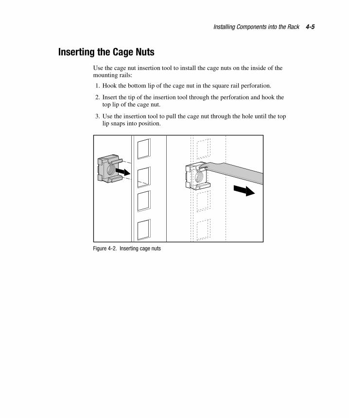
Inserting the Cage NutsUse the cage nut insertion tool to install the cage nuts on the inside of themounting rails:
1. Hook the bottom lip of the cage nut in the square rail perforation.
2. Insert the tip of the insertion tool through the perforation and hook thetop lip of the cage nut.
3. Use the insertion tool to pull the cage nut through the hole until the toplip snaps into position.
Figure 4-2. Inserting cage nuts

4-6 Compaq 9000 Series Rack Products Reference Guide
Compaq Confidential – Need to Know RequiredWriter: Amy L. Laffitte Project: Compaq 9000 Series Rack Products Reference Guide Comments: FINAL
Part Number: 142553-xx3 File Name: e-ch4.doc Last Saved On: 6/26/01 12:57 PM
Installing the RailsThere are two types of rack-mount rails:
� Adjustable fixed rails
� Sliding rails
Installing the Adjustable Fixed Rail
Components mounted with this type of rail are typically designed to slide intothe rack one time, for initial installation. The function of adjustable fixed railsis to support the component in the rack.
1. Loosen the wing nuts � and extend the brackets to the desired
length �.
2. Tighten the wing nuts slightly to stabilize the bracket during installation.
1 2
Figure 4-3. Adjusting the fixed rails

Installing Components into the Rack 4-7
Compaq Confidential – Need to Know RequiredWriter: Amy L. Laffitte Project: Compaq 9000 Series Rack Products Reference Guide Comments: FINAL
Part Number: 142553-xx3 File Name: e-ch4.doc Last Saved On: 6/26/01 12:57 PM
3. Insert at least one screw through each rack-mounting rail and into thefront of each adjustable rail.
NOTE: After installing your component, insert at least one more screw in each adjustablerail for additional support.
Figure 4-4. Fastening the fixed rail to the front of the rack
4. Insert the rear screws into the cage nuts installed earlier.
Figure 4-5. Fastening the fixed rail to the rear of the rack

4-8 Compaq 9000 Series Rack Products Reference Guide
Compaq Confidential – Need to Know RequiredWriter: Amy L. Laffitte Project: Compaq 9000 Series Rack Products Reference Guide Comments: FINAL
Part Number: 142553-xx3 File Name: e-ch4.doc Last Saved On: 6/26/01 12:57 PM
5. Retighten the wing nuts on the adjustable rails. The rails are now readyfor installation of your component.
Figure 4-6. Rack ready for component installation

Installing Components into the Rack 4-9
Compaq Confidential – Need to Know RequiredWriter: Amy L. Laffitte Project: Compaq 9000 Series Rack Products Reference Guide Comments: FINAL
Part Number: 142553-xx3 File Name: e-ch4.doc Last Saved On: 6/26/01 12:57 PM
Installing the Sliding Rail
Components mounted with this type of rail are designed for frequentaccessibility and/or maintenance.
1. Extend the component rail until the component rail release latch clicks �.
2. Hold down the latch � and completely remove the component rail fromthe sliding bracket rail assembly. The component rail will be attached tothe system chassis before inserting the unit into the rack.
21
Figure 4-7. Removing the component rail
4-10 Compaq 9000 Series Rack Products Reference Guide
Compaq Confidential – Need to Know RequiredWriter: Amy L. Laffitte Project: Compaq 9000 Series Rack Products Reference Guide Comments: FINAL
Part Number: 142553-xx3 File Name: e-ch4.doc Last Saved On: 6/26/01 12:57 PM
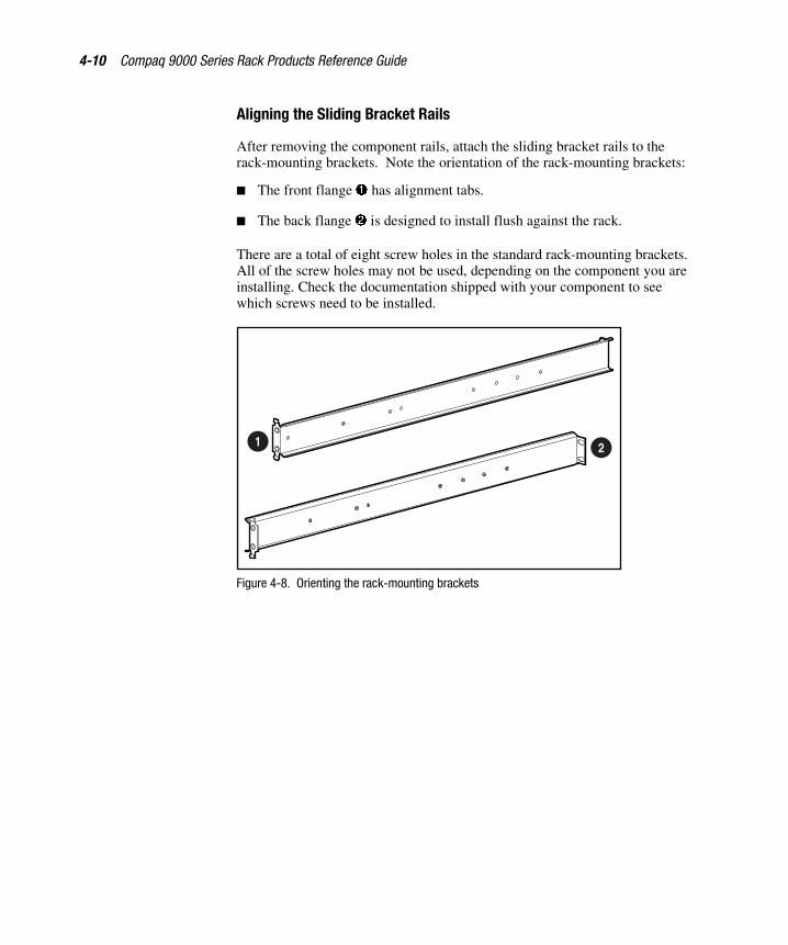
Aligning the Sliding Bracket Rails
After removing the component rails, attach the sliding bracket rails to therack-mounting brackets. Note the orientation of the rack-mounting brackets:
� The front flange � has alignment tabs.
� The back flange � is designed to install flush against the rack.
There are a total of eight screw holes in the standard rack-mounting brackets.All of the screw holes may not be used, depending on the component you areinstalling. Check the documentation shipped with your component to seewhich screws need to be installed.
1 2
Figure 4-8. Orienting the rack-mounting brackets

Installing Components into the Rack 4-11
Compaq Confidential – Need to Know RequiredWriter: Amy L. Laffitte Project: Compaq 9000 Series Rack Products Reference Guide Comments: FINAL
Part Number: 142553-xx3 File Name: e-ch4.doc Last Saved On: 6/26/01 12:57 PM
Orienting of the Sliding Bracket Rails
Note the orientation of the sliding bracket rails:
� The front of the sliding bracket rail � allows the inner slide to moveforward on ball bearings.
� The back end � has a stop for the inner slide.
While matching fronts, lay one rack-mounting bracket and one sliding bracketrail together so that the screw holes are aligned.
1
2
Figure 4-9. Orienting the sliding bracket rails

4-12 Compaq 9000 Series Rack Products Reference Guide
Compaq Confidential – Need to Know RequiredWriter: Amy L. Laffitte Project: Compaq 9000 Series Rack Products Reference Guide Comments: FINAL
Part Number: 142553-xx3 File Name: e-ch4.doc Last Saved On: 6/26/01 12:57 PM
Attaching the Sliding Bracket Rails 1. Extend the inner slide until the screw holes in the rack-mounting bracketand the sliding bracket rail are aligned �. There are two exposed holesnear the back of the sliding bracket rail and one that is accessiblethrough a slot in the inner slide. Use 8-32 x 3/8 screws to attach thesliding bracket rail to the rack-mounting bracket.
2. Adjust the inner slide until you can access another screw hole �. Insertan 8-32 x 3/8 screw.
3. Adjust the inner slide again and insert the last screw �.
1
2
3
Figure 4-10. Attaching the sliding bracket rails to the rack-mounting brackets

Installing Components into the Rack 4-13
Compaq Confidential – Need to Know RequiredWriter: Amy L. Laffitte Project: Compaq 9000 Series Rack Products Reference Guide Comments: FINAL
Part Number: 142553-xx3 File Name: e-ch4.doc Last Saved On: 6/26/01 12:57 PM
4. Attach the front of the rack-mounting bracket assembly to the inside ofthe front mounting rail of the rack using two M6 x 16 screws. The tabson the front of the rack-mounting bracket help to align it correctly withthe mounting rail.
Figure 4-11. Attaching the front of the rack-mounting bracket assembly
5. Align the rack-mounting bracket assembly with the back mounting railof the rack. Secure the back of the rack-mounting bracket to the back ofthe mounting rail with two M6 x 16 screws. Insert the screws throughthe cage nuts.
Figure 4-12. Attaching the back rack-mounting bracket assembly

4-14 Compaq 9000 Series Rack Products Reference Guide
Compaq Confidential – Need to Know RequiredWriter: Amy L. Laffitte Project: Compaq 9000 Series Rack Products Reference Guide Comments: FINAL
Part Number: 142553-xx3 File Name: e-ch4.doc Last Saved On: 6/26/01 12:57 PM
Preparing the Component ChassisBefore installing the component into the rack, you must install all therack-mountable hardware.
Adjustable Fixed Rails
If the component mounts with fixed rails, typically there is nothing additionalto install on the component chassis. The component slides into place along therails you installed in the rack.
For a sliding rail installation, you need to install rails on the component beforeyou can insert it into the rack.
1. Locate the component rails that you set aside earlier after removingthem from the sliding bracket rails.
2. Use three 8-32 x 3/8 screws to install each component rail on the side ofthe chassis.
Figure 4-13. Attaching the component rails to the chassis

Installing Components into the Rack 4-15
Compaq Confidential – Need to Know RequiredWriter: Amy L. Laffitte Project: Compaq 9000 Series Rack Products Reference Guide Comments: FINAL
Part Number: 142553-xx3 File Name: e-ch4.doc Last Saved On: 6/26/01 12:57 PM
Cable Management Arm Bracket
If the component uses a cable management arm, attach the bracket thatsupports the cable management arm to the component chassis with two6-32 x 1/4 screws.
NOTE: The cable management arm is installed after the component is installed into therack.
Figure 4-14. Attaching the cable management arm bracket to the unit

4-16 Compaq 9000 Series Rack Products Reference Guide
Compaq Confidential – Need to Know RequiredWriter: Amy L. Laffitte Project: Compaq 9000 Series Rack Products Reference Guide Comments: FINAL
Part Number: 142553-xx3 File Name: e-ch4.doc Last Saved On: 6/26/01 12:57 PM
Installing the Component into the RackThese are general instructions for installing a typical Compaq rack-mountablecomponent. See the documentation that shipped with each component forcomplete installation instructions.
After all rack-mounting hardware has been installed on the component, youcan insert it into the rack.
WARNING: Components can be very heavy. To reduce the risk ofpersonal injury or damage to the equipment:
� Remove all pluggable power supplies and modules to reducethe weight of the product before lifting it.
� Observe local occupational health and safety requirements andguidelines for manual material handling.
� Get help to lift and stabilize the product during installation orremoval, especially when the product is not fastened to therails.
� When installing the product into or removing the product fromthe rack, the product is unstable when not fastened to the rails.

Installing Components into the Rack 4-17
Compaq Confidential – Need to Know RequiredWriter: Amy L. Laffitte Project: Compaq 9000 Series Rack Products Reference Guide Comments: FINAL
Part Number: 142553-xx3 File Name: e-ch4.doc Last Saved On: 6/26/01 12:57 PM
Inserting the Component into the Rack
To insert a component into the rack:
1. Read and adhere to the previous warning. The component can be heavy.Be sure that you have an adequate number of individuals, or amechanical lifting device to help you insert the component into the rack.
2. Fully extend the sliding bracket rails.
3. With the unit well supported, lift it up and align the component rails onthe chassis with the sliding bracket rails mounted on the rack. Slide theunit into the rack until it clicks into the latches on the component rails.
4. Press in the component rail release latches on either side of the chassisand slide the unit all the way back into the rack.
5. Using the cage nuts, tighten the thumbscrews on the front of the unit tosecure it to the rack.
I0
Figure 4-15. Inserting the unit into the rack
NOTE: The first time you slide the unit into the rack, you may have to apply somepressure to loosen the ball bearings. After that, they should slide easily.

4-18 Compaq 9000 Series Rack Products Reference Guide
Compaq Confidential – Need to Know RequiredWriter: Amy L. Laffitte Project: Compaq 9000 Series Rack Products Reference Guide Comments: FINAL
Part Number: 142553-xx3 File Name: e-ch4.doc Last Saved On: 6/26/01 12:57 PM
Attaching the Cable Management Arm 1. Extend the cable management arm and bend the hinged bracket to theright.
2. Use two M6 x 12 Phillips screws to attach the cable management arm tothe bracket you installed on the chassis earlier.
Figure 4-16. Attaching the cable management arm to the bracket

Installing Components into the Rack 4-19
Compaq Confidential – Need to Know RequiredWriter: Amy L. Laffitte Project: Compaq 9000 Series Rack Products Reference Guide Comments: FINAL
Part Number: 142553-xx3 File Name: e-ch4.doc Last Saved On: 6/26/01 12:57 PM
Attaching the Cables 1. Attach any cables that need to be connected to the component.
2. To attach the power cord:
a. Remove the label covering the AC power outlet.
b. Set the input voltage selection switch to the appropriate position.
c. Attach the AC power cord to the unit.
d. Plug the AC power cord to a grounded AC outlet.
When using optional power distribution devices, make sure that groundintegrity is maintained for each connection by plugging each component into areliably grounded outlet.
WARNING: To reduce the risk of electrical shock or damage to the equipment:
� Do not disable the power cord grounding plug. The grounding plug is animportant safety feature.
� Plug the power cord into a grounded (earthed) electrical outlet that is easilyaccessible at all times.
CAUTION: Make sure that the voltage selection switch is in the proper position(115 VAC or 230 VAC). Failure to do so will result in damage to the equipment.
Figure 4-17. Attaching the AC power cord

4-20 Compaq 9000 Series Rack Products Reference Guide
Compaq Confidential – Need to Know RequiredWriter: Amy L. Laffitte Project: Compaq 9000 Series Rack Products Reference Guide Comments: FINAL
Part Number: 142553-xx3 File Name: e-ch4.doc Last Saved On: 6/26/01 12:57 PM
Removing the Cable Access Panel
The right rear door of the Compaq 9842 Rack has a separate cable accesspanel at the bottom of the door. This panel allows the user to route andmanage cables, without removing the right rear door. The Cable Access Panelcan also be removed without removing the right rear door.
To remove the cable access panel:
1. Rotate the rear right door handle to the right.
2. Pull the handle to open the door �.
3. Unscrew the two fasteners � and remove the panel from the hinge
pins �.
IMPORTANT: Retain fasteners and hinge brackets for later steps.
4. Remove the panel from the hinge bracket �. Store the access panel in anupright position, taking care to protect the rear panel from damage.
1 3
3
2
4
Figure 4-18. Removing the cable access panel

Installing Components into the Rack 4-21
Compaq Confidential – Need to Know RequiredWriter: Amy L. Laffitte Project: Compaq 9000 Series Rack Products Reference Guide Comments: FINAL
Part Number: 142553-xx3 File Name: e-ch4.doc Last Saved On: 6/26/01 12:57 PM
Routing the Cables for Server/Storage Applications
To route the cables down the cable conduit for server/storage applications:
1. Align the screw retaining plate behind the mounting rail at the rear ofthe rack.
2. Attach the cable management arm to the rail with two 10-32 x 5/8screws.
Figure 4-19. Attaching the cable management arm to the rack
NOTE: As you slide the unit in and out of the front of the rack, the cable managementarm collapses and extends so that the cables remain connected to the unit and stayuntangled.
3. Secure any cables that you attach to the component to this arm.
4. Bundle all of the cables with the cable arm extended, including thepower cable.
5. Secure the cables to the cable management arm with the fastenersprovided.
NOTE: Leave enough slack in the cables so that you can bend the cable managementarm easily.

4-22 Compaq 9000 Series Rack Products Reference Guide
Compaq Confidential – Need to Know RequiredWriter: Amy L. Laffitte Project: Compaq 9000 Series Rack Products Reference Guide Comments: FINAL
Part Number: 142553-xx3 File Name: e-ch4.doc Last Saved On: 6/26/01 12:57 PM
6. Route the bundled cables over the top of the cable management arm anddown the cable conduit.
7. Route each component cable through the desired single opening of thecable conduit.
IMPORTANT: To avoid confusion, be consistent with the order in which each componentcable is routed through the single opening of the conduit.
Figure 4-20. Routing the cables for server/storage applications
The component is now securely mounted in the rack.

Installing Components into the Rack 4-23
Compaq Confidential – Need to Know RequiredWriter: Amy L. Laffitte Project: Compaq 9000 Series Rack Products Reference Guide Comments: FINAL
Part Number: 142553-xx3 File Name: e-ch4.doc Last Saved On: 6/26/01 12:57 PM
Routing the Cables for Switching Applications
To route the cables down the conduit for switching applications:
Route each component cable through the desired single opening of the cableconduit.
Figure 4-21. Routing the cables for switching applications
IMPORTANT: To avoid confusion, be consistent with the order in which each componentcable is routed through the single opening of the conduit.

4-24 Compaq 9000 Series Rack Products Reference Guide
Compaq Confidential – Need to Know RequiredWriter: Amy L. Laffitte Project: Compaq 9000 Series Rack Products Reference Guide Comments: FINAL
Part Number: 142553-xx3 File Name: e-ch4.doc Last Saved On: 6/26/01 12:57 PM
Attaching Power CablesAfter all cables and power cords have been routed to their proper destinations,attach the power cords to a main power switch such as a properly rated powerdistribution unit.
If you are not using a power distribution unit, route the power cords directly toa properly rated and grounded AC wall or floor outlet.
WARNING: To reduce the risk of electrical shock or damage to the equipment:
� Do not disable the power cord grounding plug. The grounding plug is animportant safety feature.
� Plug the power cord into a grounded (earthed) electrical outlet that iseasily accessible at all times.
CAUTION: Make sure that the voltage selection switch is in the proper position(115 VAC or 230 VAC). Failure to do so will result in damage to the equipment.

Compaq Confidential – Need to Know RequiredWriter: Amy L. Laffitte Project: Compaq 9000 Series Rack Products Reference Guide Comments: FINAL
Part Number: 142553-xx2 File Name: f-ch5.doc Last Saved On: 6/26/01 12:58 PM
Chapter 5Options
The following options are available for use with your 9000 Series racks:
� Compaq 1U Keyboard Drawer Option Kit
� Compaq 25-inch Rail Adapter Option Kit
� Compaq Ballast Rack Option Kit
� Compaq Blanking Panels Rack Option Kit
� Compaq Cable Management Bracket Rack Option Kit
� Compaq Rack Option Baying Kit
� Compaq 9000 Rack Series Extension Option Kit
� Compaq Fan (110V/220V) Option Kit
� Compaq Ground Bonding Option Kit
� Compaq 9000 Rack Series Short Rear Door Option Kit
� Compaq Side Panel (36U/42U) Option Kit
� Compaq 9000 Rack Series Stabilizer Option Kit
� Standard Full-Size Feet
� Optional Modified Side Feet

5-2 Compaq 9000 Series Rack Products Reference Guide
Compaq Confidential – Need to Know RequiredWriter: Amy L. Laffitte Project: Compaq 9000 Series Rack Products Reference Guide Comments: FINAL
Part Number: 142553-xx2 File Name: f-ch5.doc Last Saved On: 6/26/01 12:58 PM
The following section describes the contents of these kits and specifies anyother equipment that you will need to install the kits. For completeinformation refer to the Compaq website:
www.compaq.com/racks
Rack ConsiderationsBefore beginning these procedures, make sure you understand and followthese precautions:
WARNING: To reduce the risk of personal injury or damage to the equipment besure that:
� The leveling jacks extend to the floor.
� The full weight of the rack rests on the leveling jacks.
� The stabilizing feet are attached to the rack if it is a single-rackinstallation.
� The racks are coupled in multiple-rack installations.
� Only one component is extended at a time. A rack may become unstable ifmore than one component is extended for any reason.

Options 5-3
Compaq Confidential – Need to Know RequiredWriter: Amy L. Laffitte Project: Compaq 9000 Series Rack Products Reference Guide Comments: FINAL
Part Number: 142553-xx2 File Name: f-ch5.doc Last Saved On: 6/26/01 12:58 PM
Compaq 1U Keyboard Drawer Option KitThe 1U Keyboard Drawer Option Kit is a convenient rack-mount system foreasy keyboard storage and access with any Compaq rack.
Kit Contents� Keyboard drawer (1)
� Slide brackets (2)
� Latch bracket (1)
� Beaded cable tie (extras included)
� Cable tie mount (extras included)
� Drawer cover (1)
� Rail covers (2)
� Rail cover base (2)
� Rack template card (1)
Additional Hardware
You will also need the following equipment from your original rack hardwarekit:
� Cage nuts (2)
� M6 screws (6)
Tool Required
You will also need a Phillips screwdriver.

5-4 Compaq 9000 Series Rack Products Reference Guide
Compaq Confidential – Need to Know RequiredWriter: Amy L. Laffitte Project: Compaq 9000 Series Rack Products Reference Guide Comments: FINAL
Part Number: 142553-xx2 File Name: f-ch5.doc Last Saved On: 6/26/01 12:58 PM
Compaq 25-inch Rail Adapter Option KitThe 25-inch Rail Adapter Option Kit lets you adapt the size of the inner railson Compaq 9000 Series racks to accommodate third-party rack options.
Kit Contents� Rack rail adapters (4)
� 10-32 nutbars (4)
� Self-tapping screws (8)
� 10-32 screws (16)
� Square washers (16)
This kit may contain extra pieces of hardware for your convenience.
Tool Required
You will also need a Phillips screwdriver.

Options 5-5
Compaq Confidential – Need to Know RequiredWriter: Amy L. Laffitte Project: Compaq 9000 Series Rack Products Reference Guide Comments: FINAL
Part Number: 142553-xx2 File Name: f-ch5.doc Last Saved On: 6/26/01 12:58 PM
Compaq Ballast Rack Option KitThe Ballast Rack Option Kit provides additional stability when installingCompaq 9000 Series racks.
Kit Contents� Ballast assembly (2)
� 5.5-mm (0.22 inches) self-tapping screws (10)
Tool Required
You will also need a Phillips screwdriver.

5-6 Compaq 9000 Series Rack Products Reference Guide
Compaq Confidential – Need to Know RequiredWriter: Amy L. Laffitte Project: Compaq 9000 Series Rack Products Reference Guide Comments: FINAL
Part Number: 142553-xx2 File Name: f-ch5.doc Last Saved On: 6/26/01 12:58 PM
Compaq Blanking Panels Rack Option KitThe Blanking Panels Rack Option Kit allows better airflow by allowing openareas to be covered in the rack. This option can be used with all Compaq 9000Series racks.
CAUTION: To reduce the risk of damage to internal components, blankingpanels must be installed to cover any empty space at the front of the rack.
Kits Available
Six kits are available. They contain different combinations of the various panelsizes, as follows:
� 1U, 2U, 4U, and 8U panels (one of each)
� 10 (1U) panels
� 10 (2U) panels
� 10 (3U) panels
� 10 (4U) panels
� 10 (5U) panels
These kits may contain extra pieces of hardware for your convenience.
Additional Hardware
You will also need the following components from your original rackhardware kit:
� M6 screws
� Cage nuts
� Cage nut insertion tool
Tool Required
You will also need a Phillips screwdriver.

Options 5-7
Compaq Confidential – Need to Know RequiredWriter: Amy L. Laffitte Project: Compaq 9000 Series Rack Products Reference Guide Comments: FINAL
Part Number: 142553-xx2 File Name: f-ch5.doc Last Saved On: 6/26/01 12:58 PM
Compaq Cable Management BracketRack Option Kit
The Cable Management Bracket Rack Option Kit is designed for use with all9000 Series racks to assist with cable management.
Kit Contents� Cable management brackets (10)
� Cable management clips (10)
� 5.5-mm (0.22 inches) thread-forming screws (10)
This kit may contain extra pieces of hardware for your convenience.
Additional Hardware
You will also need the following components from your original rackhardware kit:
� M6 screws
� M6 cage nuts
� Cage nut insertion tool
Tool Required
You will also need a Phillips screwdriver.

5-8 Compaq 9000 Series Rack Products Reference Guide
Compaq Confidential – Need to Know RequiredWriter: Amy L. Laffitte Project: Compaq 9000 Series Rack Products Reference Guide Comments: FINAL
Part Number: 142553-xx2 File Name: f-ch5.doc Last Saved On: 6/26/01 12:58 PM
Compaq Rack Option Baying KitThe Rack Option Baying Kit allows multiple 9000 Series racks of the samesize to be connected.
NOTE: Only racks of the same height should be bayed together. Either bracket can beused for any size 9000 rack application. Compaq suggests the 24-inch (609.6 mm)baying bracket for the Compaq 9842 Rack installation.
Kit Contents� 24-inch (609.6-mm) baying brackets (6)
� 600-mm (23.6-inch) baying brackets (6)
� T-30 flathead screws (15)
Tool Required
You will also need a Phillips screwdriver.

Options 5-9
Compaq Confidential – Need to Know RequiredWriter: Amy L. Laffitte Project: Compaq 9000 Series Rack Products Reference Guide Comments: FINAL
Part Number: 142553-xx2 File Name: f-ch5.doc Last Saved On: 6/26/01 12:58 PM
Compaq 9000 Rack Series ExtensionOption Kit
The 9000 Rack Series Extension Option Kit adds 3.5 inches (88.9 mm) ofdepth to the rear of 9000 Series racks.
Kit Contents� Door extension (1)
� T-25 5.5-mm (0.22-inch) screws (6)
� T-30 screw (1)
� Screw fasteners (5)
� Grounding strap (1)
� Serrated washer (1)
� Threaded nut (1)
� Hinge
This kit may contain extra pieces of hardware for your convenience.
Additional Hardware
You will also need the following:
� T-25 screwdriver
� T-30 screwdriver
� Adjustable wrench
Tool Required
You will also need a Phillips screwdriver.

5-10 Compaq 9000 Series Rack Products Reference Guide
Compaq Confidential – Need to Know RequiredWriter: Amy L. Laffitte Project: Compaq 9000 Series Rack Products Reference Guide Comments: FINAL
Part Number: 142553-xx2 File Name: f-ch5.doc Last Saved On: 6/26/01 12:58 PM
Compaq Fan (110V/220V) Option KitThe Fan (110V/220V) Option Kit is for use with all Compaq 9000 Series racksto enhance natural convection cooling by increasing the airflow in the rack.
Kit Contents� Fan assembly (1)
� Power cord (2)
� Cable fastener (4)
Tool Required
You will also need a T-25 torx screwdriver.

Options 5-11
Compaq Confidential – Need to Know RequiredWriter: Amy L. Laffitte Project: Compaq 9000 Series Rack Products Reference Guide Comments: FINAL
Part Number: 142553-xx2 File Name: f-ch5.doc Last Saved On: 6/26/01 12:58 PM
Compaq Ground Bonding Option KitThe Ground Bonding Option Kit reduces the level of electromagnetic radiationoutside the rack. (This radiation is produced during normal operation of theelectronic components within the rack cabinet.) The kit ties all the conductivestructural components of the rack together with conductive cables, and is thenattached to a ground bonding point on the rack’s AC power distributiondevice.
Kit Contents� 6-inch (152.4 mm) grounding strap (3)
� 14.5-inch (368.3 mm) grounding strap (6)
� Mountable wire tie (10)
� M8 nut (5)
� Internal serrated lock washer (5)
� M8 x 20 hex head screw (1)
� Paint cutter washer (2)
� T-25 5.5-mm (0.22-inch) screw (14)
This kit may contain extra pieces of hardware for your convenience.
Additional Hardware
You will also need the following:
� T-25 torx screwdriver
� Adjustable wrench

5-12 Compaq 9000 Series Rack Products Reference Guide
Compaq Confidential – Need to Know RequiredWriter: Amy L. Laffitte Project: Compaq 9000 Series Rack Products Reference Guide Comments: FINAL
Part Number: 142553-xx2 File Name: f-ch5.doc Last Saved On: 6/26/01 12:58 PM
Compaq 9000 Series Rack Short RearDoor Option Kit
The 9000 Rack Series Rack Short Rear Door Option Kit provides a4U (seven-inch) opening at the bottom rear of the 9000 Series rack.
Kit Contents� Short rear door (1)
Compaq Side Panels Option KitThe Side Panels Option Kit is an option with 36U and 42U racks, but isstandard with 22U racks.
Kit Contents� Side panel (2)
� Hangers (4)
� T-30 screws (12)
� T-30 driver (1)

Options 5-13
Compaq Confidential – Need to Know RequiredWriter: Amy L. Laffitte Project: Compaq 9000 Series Rack Products Reference Guide Comments: FINAL
Part Number: 142553-xx2 File Name: f-ch5.doc Last Saved On: 6/26/01 12:58 PM
Compaq 9000 Series Rack StabilizerOption Kit
The 9000 Series Rack Stabilizer Option Kit prevents 9000 Series racks fromtipping over. Install the stabilizer kit before adding any rack components.
Kit Contents� Full-size side feet (2)
� Full-size front foot (1)
� U bracket (1)
� Self-retaining cage nuts (4)
� Thread-forming screws (13)
� Modified side feet (2)—allow you to stabilize a 9000 Series rack fromthe front when it is placed between racks of other types
This kit may contain extra pieces of hardware for your convenience.
Additional Hardware
You will also need an adjustable wrench.

Compaq Confidential – Need to Know RequiredWriter: Amy L. Laffitte Project: Compaq 9000 Series Rack Products Reference Guide Comments: FINAL
Part Number: 142553-xx3 File Name: g-appendixa.doc Last Saved On: 6/26/01 12:59 PM
Appendix AElectrostatic Discharge
To prevent damage to the system, be aware of the precautions you need tofollow when setting up the system or handling parts. A discharge of staticelectricity from a finger or other conductor may damage system boards orother static-sensitive devices. This type of damage may reduce the lifeexpectancy of the device.
To prevent electrostatic damage, observe the following precautions:
� Avoid hand contact by transporting and storing products in static-safecontainers.
� Keep electrostatic-sensitive parts in their containers until they arrive atstatic-free workstations.
� Place parts on a grounded surface before removing them from theircontainers.
� Avoid touching pins, leads, or circuitry.
� Always be properly grounded when touching a static-sensitivecomponent or assembly.

A-2 Compaq 9000 Series Rack Products Reference Guide
Compaq Confidential – Need to Know RequiredWriter: Amy L. Laffitte Project: Compaq 9000 Series Rack Products Reference Guide Comments: FINAL
Part Number: 142553-xx3 File Name: g-appendixa.doc Last Saved On: 6/26/01 12:59 PM
Grounding MethodsThere are several methods for grounding. Use one or more of the followingmethods when handling or installing electrostatic-sensitive parts:
� Use a wrist strap connected by a ground cord to a grounded workstationor computer chassis. Wrist straps are flexible straps with a minimum of1 megohm ± 10 percent resistance in the ground cords. To provideproper ground, wear the strap snug against the skin.
� Use heel straps, toe straps, or boot straps at standing workstations. Wearthe straps on both feet when standing on conductive floors or dissipatingfloor mats.
� Use conductive field service tools.
� Use a portable field service kit with a folding static-dissipating workmat.
If you do not have any of the suggested equipment for proper grounding, havea Compaq authorized reseller install the part.
NOTE: For more information on static electricity, or assistance with product installation,contact your Compaq authorized reseller.

Compaq Confidential – Need to Know RequiredWriter: Amy L. Laffitte Project: Compaq 9000 Series Rack Products Reference Guide Comments: FINAL
Part Number: 142553-xx3 File Name: h-appendixb.doc Last Saved On: 6/26/01 12:59 PM
Appendix BTransportation Instructions
Transportation MethodsDepending on your circumstances and time schedule, there are threetransportation methods for transporting your rack:
� Air
� Land
� Sea

B-2 Compaq 9000 Series Rack Products Reference Guide
Compaq Confidential – Need to Know RequiredWriter: Amy L. Laffitte Project: Compaq 9000 Series Rack Products Reference Guide Comments: FINAL
Part Number: 142553-xx3 File Name: h-appendixb.doc Last Saved On: 6/26/01 12:59 PM
Air Transport
All 9000 Series racks can be air freighted upright on a pallet or shock pallet, orhorizontally in a crate. However, since the 42U rack has a packaged height of85.4 inches (217 cm), and the maximum height for air cargo is 86 inches(218.4 cm), only the largest cargo planes can accommodate it upright. If yourdestination does not accommodate large cargo planes, the 42U rack must beair freighted horizontally in a crate.
A passenger plane with cargo space has a height limitation of 63 inches(160 cm). Because a palletized 22U rack is below this limit, it can readily bedelivered by air. It must be shipped upright on a pallet, and double stacking isnot allowed.
CAUTION: If your rack is an integrated model, it MUST be transported upright. Ifthis is not possible, remove all components from the rack and prepare them fordelivery, or choose an alternative transportation method.
Because of the dimensions and the weight of the racks, check with carriers fortheir limitations before dispatching.
Land Transport
All Compaq racks can be shipped by common carriers. Carriers providing airride capabilities are preferred.
Ship racks upright on their pallets. Do not lay the racks horizontally or doublestack them.
Because of the dimensions and the weight of the racks, please check withcarriers for their restrictions before dispatching.
Sea Transport
Racks can be transported by sea, but it takes four to six weeks for the shipmentto arrive.
Ship racks upright on their pallets. Do not lay the racks horizontally or doublestack them.
Transportation Instructions B-3
Compaq Confidential – Need to Know RequiredWriter: Amy L. Laffitte Project: Compaq 9000 Series Rack Products Reference Guide Comments: FINAL
Part Number: 142553-xx3 File Name: h-appendixb.doc Last Saved On: 6/26/01 12:59 PM
Delivery ServicesCompaq provides two methods of delivery for customers in North America:Inside Rack Delivery Service and Expedited Rack Delivery Service. Thehighlights and limitations of each method are described in the followingsections.
If you want both Inside Rack Delivery and Expedited Rack Delivery, you mustspecify both part numbers on your purchase order.
Inside Rack Delivery Service
Inside Rack Delivery Service (Part No. 184649-001) is available for receivingsites that do not have the proper facilities for the standard dock-to-dockdelivery, or when you need delivery to a specific location within a site. Therack is transported as close as possible to the desired location. If a stairway ora non-accessible doorway is encountered, the rack is left there.
Highlights
� The palletized rack is unloaded by transportation personnel.
� Transportation personnel provide material-handling equipment.
� The rack is delivered to the desired location within the facility(see “Limitations”).
� Delivery service is for a single rack.
Limitations
� If shipping a non-integrated rack, door widths and corridors must accepta 39-inch (99 cm) x 48-inch (122 cm) pallet.
� Door heights and corridors must be at least 2 meters (78.7 inches) tallfor the 42U rack.
� A proper freight elevator must be available for deliveries to upper andlower floors.
� Transportation personnel will not remove the rack from the shippingpallet.
� Transportation personnel will not remove the pallet or packaging.

B-4 Compaq 9000 Series Rack Products Reference Guide
Compaq Confidential – Need to Know RequiredWriter: Amy L. Laffitte Project: Compaq 9000 Series Rack Products Reference Guide Comments: FINAL
Part Number: 142553-xx3 File Name: h-appendixb.doc Last Saved On: 6/26/01 12:59 PM
Expedited Rack Delivery Service
Expedited Rack Delivery Service (Part No. 184449-001) is available in therare instances when air shipment of the rack is required.
Highlights
� Special packaging, such as crating, is provided as required.
� Shipment is made by a Compaq-selected air carrier.
� Delivery service is for a single rack.
Limitations
� This service is available only in the continental United States, Alaska,and Hawaii.
� Inside rack delivery is not included.
Shipping/Delivery Considerations
The following precautions should be observed when receiving the racks andcomponents.
� A dock door is needed at the receiving site to accommodate the heightand width of the palletized racks.
� When shipping a rack, the 48-inch (122-cm) x 39-inch (99-cm) palletdoes not fit through a standard-width internal door, which is about30 inches (76.2 cm) wide.
� The palletized 42U rack is approximately 85 inches (216 cm) high anddoes not fit through a standard-height door.
� Do not lay the rack horizontally, because the sheet metal can wrenchand distort.
� Transport the rack as far into the building as possible while still on thepallet. Then remove the rack from the pallet and roll the rack on itscasters, being careful to keep the rack from tipping. Ideally, thepalletized rack should be moved to its final destination, then removedfrom the pallet.

Compaq Confidential – Need to Know RequiredWriter: Amy L. Laffitte Project: Compaq 9000 Series Rack Products Reference Guide Comments: FINAL
Part Number: 142553-xx3 File Name: i-appendixc.doc Last Saved On: 6/26/01 1:00 PM
Appendix CSpecifications
Model 9122
Table C-122U Rack Physical Characteristics
Feature U.S. Metric
Dimensions Cabinet size Height 43.0 in 1092 mm
Depth 35.8 in 909 mm
Width 23.7 in 603 mm
Height 52.3 in 1328 mm
Depth 48.0 in 1219 mm
Shipping size (withpackaging materials)
Width 32.0 in 813 mm
Weight Operating 165 lb 75 kg
Shipping 225 lb 102 kg
Color Opal

C-2 Compaq 9000 Series Rack Products Reference Guide
Compaq Confidential – Need to Know RequiredWriter: Amy L. Laffitte Project: Compaq 9000 Series Rack Products Reference Guide Comments: FINAL
Part Number: 142553-xx3 File Name: i-appendixc.doc Last Saved On: 6/26/01 1:00 PM
Model 9136
Table C-236U Rack Physical Characteristics
Feature U.S. Metric
Dimensions Cabinet size Height 68.6 in 1742 mm
Depth 35.8 in 909 mm
Width 23.7 in 603 mm
Height 75.3 in 1913 mm
Depth 48.0 in 1219 mm
Shipping size (withpackaging materials)
Width 32.0 in 813 mm
Weight Operating 176 lb 80 kg
Shipping 234 lb 106 kg
Color Opal
Model 9142
Table C-342U Rack Physical Characteristics
Feature U.S. Metric
Dimensions Cabinet size Height 78.7 in 2000 mm
Depth 35.8 in 909 mm
Width 23.7 in 603 mm
Height 85.4 in 2220 mm
Depth 48 in 1219 mm
Shipping size (withpackaging materials)
Width 32 in 813 mm
Weight Operating 253 lb 115 kg
Shipping 325 lb 148 kg
Color Opal

Specifications C-3
Compaq Confidential – Need to Know RequiredWriter: Amy L. Laffitte Project: Compaq 9000 Series Rack Products Reference Guide Comments: FINAL
Part Number: 142553-xx3 File Name: i-appendixc.doc Last Saved On: 6/26/01 1:00 PM
Model 9842
Table C-442U Rack Physical Characteristics
Feature U.S. Metric
Dimensions Total Cabinet Area Height 78.7 in 2000 mm
Depth 35.8 in 909 mm
Width 31.5 in 800 mm
Shipping (with Height 83.4 in 2118 mm
packaging materials) Depth 47.8 in 1214 mm
Width 38.8 in 985.52 mm
Weight Operating 374 lb 170 kg
Shipping 440 lb 200 kg
Color Opal
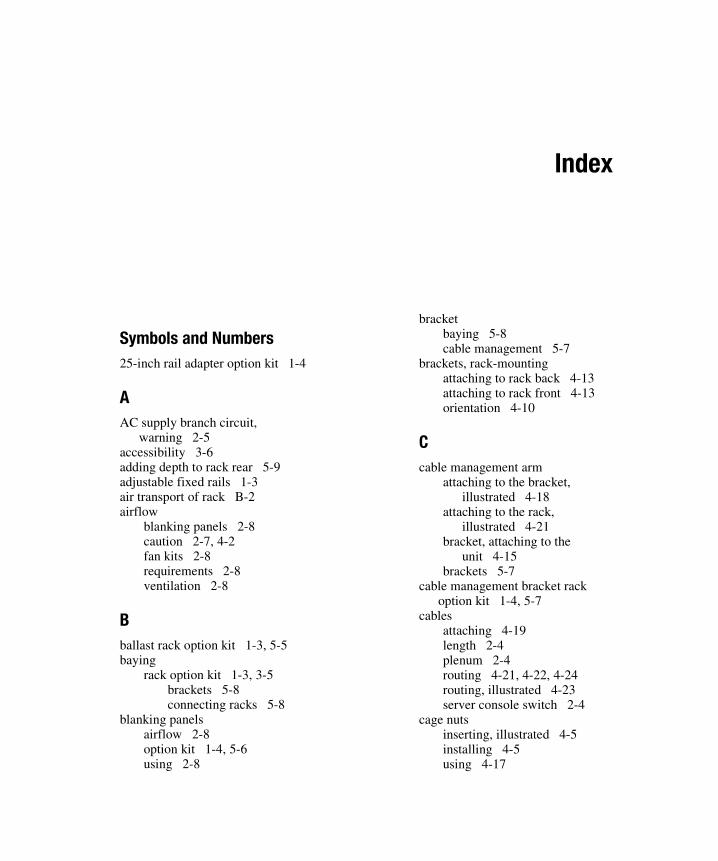
Compaq Confidential – Need to Know RequiredWriter: Amy L. Laffitte Project: Compaq 9000 Series Rack Products Reference Guide Comments: 1st draft
Part Number: 142553-003 File Name: x-index.doc Last Saved On: 6/26/01 1:00 PM
Index
Symbols and Numbers25-inch rail adapter option kit 1-4
AAC supply branch circuit,
warning 2-5accessibility 3-6adding depth to rack rear 5-9adjustable fixed rails 1-3air transport of rack B-2airflow
blanking panels 2-8caution 2-7, 4-2fan kits 2-8requirements 2-8ventilation 2-8
Bballast rack option kit 1-3, 5-5baying
rack option kit 1-3, 3-5brackets 5-8connecting racks 5-8
blanking panelsairflow 2-8option kit 1-4, 5-6using 2-8
bracketbaying 5-8cable management 5-7
brackets, rack-mountingattaching to rack back 4-13attaching to rack front 4-13orientation 4-10
Ccable management arm
attaching to the bracket,illustrated 4-18
attaching to the rack,illustrated 4-21
bracket, attaching to theunit 4-15
brackets 5-7cable management bracket rack
option kit 1-4, 5-7cables
attaching 4-19length 2-4plenum 2-4routing 4-21, 4-22, 4-24routing, illustrated 4-23server console switch 2-4
cage nutsinserting, illustrated 4-5installing 4-5using 4-17

2 Compaq 9000 Series Rack Products Reference Guide
Compaq Confidential – Need to Know RequiredWriter: Amy L. Laffitte Project: Compaq 9000 Series Rack Products Reference Guide Comments: 1st draft
Part Number: 142553-003 File Name: x-index.doc Last Saved On: 6/26/01 1:00 PM
casters, caution 3-3cautions
airflow and temperature 4-2casters 3-3proper airflow and
temperature 2-7verify AC voltage selector
switches 2-6voltage selection switch 4-19,
4-24characteristics
Model 9122 C-1Model 9136 C-2Model 9142 C-2Model 9842 C-3
clearancearound power supply 2-5between wall and rack 4-2rack back 2-5rack front 2-5to unpack 2-5
Compaqauthorized reseller xiwebsite ix
component placementby weight 2-3configuring 2-3CRT 2-3desired viewing height 2-3flat panel monitor 2-3monitor 2-3switch box 2-3
componentsinserting into rack 4-17inserting into rack,
illustrated 4-17installation 4-16installation guidelines 4-2preparing for installation 4-14removing rail, illustrated 4-9warning 4-16weight distribution/in rack 4-2
conductive cablesfor ground bonding option
kit 5-11
configurationRack Builder Online 4-2rack, planning 2-1utility 2-1
considerationsbaying racks 2-4height 2-3keyboard 2-3monitor 2-4power 2-3sidewall panels 2-4
Ddelivery
considerations B-4receiving B-4service
expedited B-4inside B-3
depth-adjustable fixed rails 1-3dimensions
Model 9122 C-1Model 9136 C-2Model 9142 C-2Model 9842 C-3
doorsopening, illustrated 3-6removing, illustrated 3-7replacing 3-7
drawer, for keyboard 1-3
Eelectromagnetic radiation,
reducing 5-11electrostatic discharge
precautions A-1preventing A-1
environment 2-5expedited delivery service B-4extension option kit 1-4, 5-9

Index 3
Compaq Confidential – Need to Know RequiredWriter: Amy L. Laffitte Project: Compaq 9000 Series Rack Products Reference Guide Comments: 1st draft
Part Number: 142553-003 File Name: x-index.doc Last Saved On: 6/26/01 1:00 PM
Ffan (110V/220V) rack option
kit 1-3, 5-10features, 9000 Series rack
Rack Builder Online 2-2feet 5-13fixed rails 4-6, 4-14
installing 4-6flat panel monitor
component placement 2-3
Ggaps 2-8ground bonding option kit 1-3,
5-11grounding
methods A-2requirements 2-6straps 5-9, 5-11
guidelines for componentinstallation 4-2
Hhardware shipped with rack 3-2height considerations 2-3
Iicons
symbols on equipment viiiinner rails
25-inch rail adapter 5-4inside delivery service B-3installation
adjustable fixed rails 4-6cable management arm 4-18cable management
bracket 4-15cage nuts 4-5components 4-17sequence of components 4-3sliding rails 4-9summary 1-5
Kkeyboard
1U drawer option kit 1-3, 5-3required parts 2-3
kit components list 3-2
Lland transport of rack B-2leveling feet 3-3
Mmanagement clips 5-7Model
9122 specifications C-19136 specifications C-29142 specifications C-29842 specifications C-3
monitorflat panel 1-3placement 2-3required parts 2-4
monitor/utility shelf 1-3multiple racks 3-5
NNational Electric Code 2-6National Electrical
Regulations 2-4nutbars 5-4
Ooptions
1U keyboard drawer optionkit 5-3
25-inch rail adapter kit 1-4,5-4
ballast rack option kit 1-3, 5-5blanking panels option kit 1-4,
5-6cable management bracket
rack option kit 1-4, 5-7

4 Compaq 9000 Series Rack Products Reference Guide
Compaq Confidential – Need to Know RequiredWriter: Amy L. Laffitte Project: Compaq 9000 Series Rack Products Reference Guide Comments: 1st draft
Part Number: 142553-003 File Name: x-index.doc Last Saved On: 6/26/01 1:00 PM
depth-adjustable rails 1-3extension option kit 1-4, 5-9fan (110V/220V) rack option
kit 1-3, 5-10flat panel monitor 1-3ground bonding option kit
1-3, 5-11monitor/utility shelf kit 1-3networking cable kit 1-4rack option baying kit 1-3, 5-8rack transporting kit 1-4recessed rail management
kit 1-4server console switch 1-4shock pallet spares kit 1-4short rear door kit 5-12side panel option kit 1-3, 5-12sliding shelf kit 1-3stabilizer option kit 1-3, 5-13switch box 1-4
Ppaint cutter washer 5-11PDUs 2-3, 4-19planning a rack configuration 2-1plenum cables 2-4power
considerations 2-3cords
attaching 4-19attaching, illustrated 4-19grounding feature, warning 2-6grounding, warning 4-19, 4-24routing 4-24
distribution See PDUsrequirements 2-5
Rrack
accessibility 3-6baying 2-4configuration utility 1-5hardware list 3-2joining 2-4
outside dimensions 2-5ready for component
installation, illustrated 4-8setup, completing 3-6shipping by air B-2shipping by land B-2shipping by sea B-2stability, warning 3-3, 4-2standalone, stabilizing 3-3transporting 1-4unpacking, space required 2-5
Rack Builder Online 1-5, 2-1, 4-2help me build it mode 2-1let me build it mode 2-1
rack configuration softwaredrag and drop 2-2features 2-1graphics 2-2labeling 2-2multiple rack
configuration 2-2reports 2-2third-party reports 2-2
rack kit components list 3-2rack-mounting brackets
attaching to rack back 4-13attaching to rack front 4-13attaching to rack,
illustrated 4-13orientation 4-10orienting, illustrated 4-10
racksjoining multiple 2-4options 5-1

Index 5
Compaq Confidential – Need to Know RequiredWriter: Amy L. Laffitte Project: Compaq 9000 Series Rack Products Reference Guide Comments: 1st draft
Part Number: 142553-003 File Name: x-index.doc Last Saved On: 6/26/01 1:00 PM
railscomponent
attaching to the chassis 4-14attaching to the chassis,
illustrated 4-14removing, illustrated 4-9
depth-adjustable 1-3fixed 4-6, 4-14
attaching to rack, illustrated 4-7sliding 4-9, 4-14sliding bracket
aligning 4-10attaching to the rack mounting
brackets, illustrated 4-12orienting 4-11orienting, illustrated 4-11
rear rack, adding depth to 5-9receiving B-4recessed rail management kit 1-4requirements
airflow 2-8blanking panels 2-8grounding 2-6power 2-5space 2-5temperature 2-7
RJ-45 receptacle viii
Ssea transport of rack B-2self-retaining cage nuts 5-13self-tapping screws 5-5serrated
lock washer 5-11washer 5-9
server console switch 1-4placement 2-3required parts 2-4
shelfmonitor/utility 1-3sliding 1-3
shippingconsiderations B-4rack by air B-2rack by land B-2rack by sea B-2
shock pallet spares kit 1-4short rear door option kit 5-12side panel option kit 1-3, 5-12sidewall panels
considerations 2-4removing, illustrated 3-8
sliding bracket rails 4-10attaching to the rack-mounting
brackets, illustrated 4-12orienting 4-11orienting, illustrated 4-11
sliding rails 4-9, 4-14installing 4-9
sliding shelf 1-3space required 2-5
between wall and rack 4-2specifications
Model 9122 C-1Model 9136 C-2Model 9142 C-2Model 9842 C-3
square washers 5-4stability of rack, warning 3-3stabilizer option kit 5-13stabilizing feet
attached, illustrated 3-4using 3-4warning 3-4
standalone racks, stabilizing 3-3switch box See server console
switchsymbols
in text viiion equipment viii

6 Compaq 9000 Series Rack Products Reference Guide
Compaq Confidential – Need to Know RequiredWriter: Amy L. Laffitte Project: Compaq 9000 Series Rack Products Reference Guide Comments: 1st draft
Part Number: 142553-003 File Name: x-index.doc Last Saved On: 6/26/01 1:00 PM
Ttechnical support xtelephone numbers xitemperature
ambient 2-7caution 4-2maximum 2-7maximum, caution 2-7operating 2-7requirements 2-7
templatemeasuring with, illustrated 4-4using 4-4
text conventions viithird-party racks,
accommodating 5-4threaded nut 5-9tools needed 3-2
UUPS 2-3
Vventilation
airflow 2-8voltage selection switch,
caution 2-6, 4-19, 4-24
Wwarnings
AC supply branch circuit 2-5components 4-16electrical shock ixinstalling options 5-2power cord grounding 4-19power cord grounding
feature 2-6power cord grounding
plug 4-24rack stability ix, 3-3, 4-2stabilizing feet 3-4
washerpaint cutter 5-11serrated 5-9serrated lock 5-11square 5-4
weight 2-3balancing between racks 2-3component placement 2-3connecting racks 2-3Model 9122 C-1Model 9136 C-2Model 9142 C-2Model 9842 C-3
wiring requirements 2-4