harmony - ec1.images-amazon.comec1.images-amazon.com/media/i3d/01/a/man-migrate/manual000024… ·...
TRANSCRIPT

Harmony
Harmony Access Point ControllerUser's Guide
Copyright© 2002 Proxim Corporation, Sunnyvale, CA. All rights reserved. This user’s guide and the software described in it are copyrighted with all rights reserved. No part of this publication may be reproduced, transmitted, transcribed, stored in a retrieval system, or translated into any language in any form by any means without the written permission of Proxim Corporation.
TrademarksHarmony, 2X, RangeLAN2, RangeLAN, the RangeLAN logo, Proxim, and the Proxim logo are trademarks of Proxim Corporation. All other trademarks are the property of their respective owners.
Limited Warranty, Disclaimer, Limitation Of LiabilityFor a period of one (1) year from the date of purchase by the retail customer, Proxim warrants the Harmony Access Point Controller Model 7560 against defects in materials and workmanship. Proxim will not honor this warranty if there has been any attempt to tamper with or remove the product’s external foil label.
This warranty does not cover and Proxim will not be liable for any damage or failure caused by misuse, abuse, acts of God, accidents, or other causes beyond Proxim’s control, or claim by any entity other than the original purchaser.
If, after inspection, Proxim determines there is a defect, Proxim will repair or replace the Harmony Access Point Controller at no cost to you. To return defective merchandise to Proxim, please call Proxim Technical Support at 1-408-731-2640 to obtain a Return Merchandise Authorization (RMA) number.
In no event shall Proxim Corporation be responsible or liable for any damages arising:
• From the use of the product
• From the loss of use, revenue or profit of the product
• As a result of any event, circumstance, action or abuse beyond the control of Proxim Corporation
Whether such damages be direct, indirect, consequential, special or otherwise and whether such damages are incurred by the person to whom this warranty extends or a third party.
Warranty Return PolicyIf you have a problem with the Harmony Access Point Controller Model 7560, please call Proxim Technical Support at 1-408-731-2640. Proxim Technical Support will assist with resolving any technical difficulties you may have with your Proxim product.
After calling Proxim Technical Support, if your product is found to be defective, you may return the product to Proxim after obtaining an RMA (Return Merchandise Authorization) number. The product must be returned in its original packaging. The RMA number should be clearly marked on the outside of the box. Proxim cannot be held responsible for any product returned without an RMA number, and no product will be accepted without an RMA number.
FCC WARNINGThis equipment has been tested and found to comply with the limits for a Class B digital device, pursuant to Part 15 of the FCC Rules. These limits are designed to provide reasonable protection against harmful interference in a residential installation. This equipment generates, uses, and can radiate radio frequency energy and, if not installed and used in accordance with the instructions, may cause harmful interference to radio communications. However, there is no guarantee that interference will not occur in a particular installation. If this equipment does cause harmful interference to radio or television reception, which can be determined by turning the equipment off and on, the user is encouraged to try to correct the interference by one or more of the following measures:
• Reorient or relocate the receiving antenna.
• Increase the separation between the equipment and the receiver.
• Connect the equipment into an outlet on a circuit different from that which the receiver is connected.
• Consult the dealer or an experienced radio/TV technician for help.
Harmony 7560 Access Point Controller User’s GuidePart # 2050.0461Rev. B

3
Table of Contents
Chapter 1 - Introduction .................................................................................. 6
The Harmony Family ....................................................................................... 7System Requirements ....................................................................................8The Product Package .....................................................................................8AP Controller LEDs .........................................................................................9
Front Panel ..............................................................................................9Back Panel ............................................................................................. 10
Chapter 2 - Installation .................................................................................. 11
Installing the AP Controller .......................................................................... 12Rack Mounting the AP Controller ............................................................ 13
Installing a Harmony 802.11a Access Point .................................................. 14Installing a Harmony 802.11b Access Point .................................................. 16Installing a Harmony OpenAir Access Point .................................................. 18
Chapter 3 - Wireless Topologies ..................................................................... 20
Harmony Tunneling Architecture .................................................................. 21Network With a Single AP Controller ............................................................. 22Network With Multiple AP Controllers ........................................................... 23Roaming Between Access Points .................................................................. 24
Roaming Across a Router ....................................................................... 25Roaming Guidelines ............................................................................... 25
Networks That Already Use RangeLAN2 ........................................................26
Chapter 4 - Configuration .............................................................................. 27
Accessing the Web Browser Interface ........................................................... 27AP Controller’s IP Address ............................................................................28
IP Address Assigned by DHCP ................................................................28Default IP Address .................................................................................29Static IP Address ....................................................................................29
Access Point Configuration .......................................................................... 31Manually Adding a New Access Point ..................................................... 31Removing an Access Point ..................................................................... 33Upgrading an Access Point ..................................................................... 34

4
Chapter 5 - Configuration Parameters ............................................................ 35
System Parameters ...................................................................................... 36System Access ....................................................................................... 37Filters .................................................................................................... 37Subnet Table ......................................................................................... 41Authorization Table ................................................................................ 43Advanced .............................................................................................. 45Security (Wired Server Address Filter) .....................................................46SNMP .................................................................................................... 47User Database Configuration .................................................................48
AP Controller Parameters ..............................................................................51System ID ...............................................................................................51AP Controller Name ................................................................................ 52Physical Address ................................................................................... 52IP Address ............................................................................................. 52
Access Point Parameters .............................................................................. 53802.11a Access Point Parameters ........................................................... 54802.11b Access Point Parameters ........................................................... 61Open Air Access Point Parameters .......................................................... 65
AP AutoConfigure Defaults ...........................................................................69802.11a AutoConfigure Default Parameters ............................................69802.11b AutoConfigure Default Parameters ............................................ 70OpenAir AutoConfigure Default Parameters .............................................71Generic AP AutoConfigure Defaults ........................................................ 72
Chapter 6 - Status ......................................................................................... 74
AP Controller Status ..................................................................................... 74Access Point Status ..................................................................................... 75Station Status .............................................................................................. 76RangeLAN2 Access Point Status ................................................................... 78
Chapter 7 - Statistics .................................................................................... 79
AP Controller Statistics ................................................................................ 79Ethernet Statistics ................................................................................. 79Filter Statistics ....................................................................................... 81Tunneling Statistics ............................................................................... 81
Access Point Statistics ................................................................................. 83Ethernet Statistics .................................................................................84Bridge Statistics ....................................................................................84Radio Statistics ...................................................................................... 85
Station Traffic Statistics ............................................................................... 87
5
Chapter 8 - Access Point Groups .................................................................... 89
Viewing AP Groups .......................................................................................90Creating a New Group .................................................................................. 91Deleting a Group ..........................................................................................92Group Configuration .................................................................................... 93
Group Description .................................................................................. 93Group Membership ................................................................................94802.11a Group Parameters .....................................................................96802.11b Group Parameters ..................................................................... 97OpenAir Group Parameters .....................................................................98Generic AP Group Parameters ................................................................98
Group Statistics ...........................................................................................99Ethernet Statistics .................................................................................99Bridge Statistics ....................................................................................99Radio Statistics .................................................................................... 100Resetting Group Statistics .................................................................... 100
Chapter 9 - Troubleshooting ........................................................................ 101
Upgrading Harmony Devices .......................................................................101Upgrading the AP Controller ..................................................................101Upgrading an Access Point ................................................................... 103
Getting Help .............................................................................................. 104Web Browser Help Screens .................................................................. 104
Common Problems and Solutions ...............................................................105
Appendix A - Technical Specifications ........................................................... 108
Parameters ................................................................................................ 108System Parameters .............................................................................. 108Filters .................................................................................................. 109SNMP Configuration ............................................................................. 109AP Controller Parameters ......................................................................110OpenAir Access Point Parameters .........................................................110802.11a Access Point Parameters .......................................................... 111802.11b Access Point Parameters .......................................................... 113
Specifications .............................................................................................114
Appendix B - Technical Support and Training ................................................. 116
Index.......................................................................................................... 117

6
Chapter 1
Introduction
Thank you for choosing Proxim’s Harmony Access Point Controller Model 7560, a member of Proxim’s Harmony wireless infrastructure family. The Harmony product line is the first wireless networking solution to support all current and future wireless LAN standards, including OpenAir, IEEE 802.11b, and 802.11a, within a single, homogeneous architecture. Harmony provides centralized management, configuration, and security for a wireless LAN.
Harmony protects your investment in a wireless infrastructure by supporting all leading and forthcoming wireless LAN protocols. IEEE 802.11b and IEEE 802.11a devices as well as RangeLAN2 and OpenAir-compatible products are all compatible with Harmony. Customers can seamlessly transition to new LAN standards by adding low-cost access points without changing the management interface or disturbing existing users.
Harmony’s SmartArchitectureTM is the first wireless management system to provide one-click, system-wide security updates and remote office infrastructure management through a single Web-based interface.
Harmony Access Points can be connected to any portion of the Ethernet network, eliminating the need for special wireless subnets common in other installations. Harmony clients can roam seamlessly anywhere there is wireless coverage, without the need for extra client software. In addition, Harmony SmartAttachTM software simplifies installation by automatically discovering and configuring new access points upon connection to the Ethernet network.
Proxim is the pioneer in wireless broadband networking. Proxim’s unmatched expertise in radio networking technology, combined with the company’s extensive experience serving the communication needs of the mobile computing user, have kept Proxim at the forefront of the wireless LAN market.

Introduction 7
The Harmony Family
The Harmony Access Point Controller Model 7560 is a member of a product family that provides a complete wireless networking solution.
• The Harmony Access Point Controller Model 7560 centralizes the management, security, and filtering capabilities of a wireless LAN. The Access Point (AP) Controller communicates with Harmony Access Points over the Ethernet network to provide wireless network access for mobile clients. The AP Controller can sup-port multiple APs, even if each AP complies with a different wireless standard.
• The Harmony Access Point is a networking bridge that operates at Layer 2 of the OSI networking model. Working in conjunction with a Harmony AP Controller, an Access Point forwards packets between its radio and the Ethernet network. Three models of the Harmony Access Point are available to support the IEEE 802.11a, IEEE 802.11b or OpenAir wireless standards: the 802.11a Access Point Model 8569/8570/8571, the 802.11b Access Point Models 8550/8551 and the OpenAir Access Point Model 7550.
• The optional Harmony Power System provides DC power to Harmony APs over the unused pins of a twisted pair Ethernet cable.
• The Harmony 802.11a CardBus Card Model 8450 is a wireless LAN adapter that fits into a 32-bit CardBus slot in a laptop computer and complies with the IEEE 802.11a standard.
• The Harmony PC Card is a wireless LAN adapter that fits into a PCMCIA Type II slot in a laptop computer. Two models are available to support the IEEE 802.11b (8430 Series) or OpenAir (7430 Series) wireless standards.
• The Harmony CompactFlash Card is a wireless LAN adapter that fits into a CompactFlash slot in a Pocket PC. Two models are available to support the IEEE 802.11b (Model 8630) or OpenAir (Model 7630) wireless standards.
• The Harmony PCI Card is a wireless LAN adapter that fits into a standard PCI expansion slot. Two models are available to support the IEEE 802.11a (Model 8150) or 802.11b (Model 8110) wireless standards.
• The Harmony OpenAir USB Adapter Model 7230 is an OpenAir-compliant wire-less LAN adapter that connects to a Windows 98/ME/2000 computer’s Universal Serial Bus (USB) port.

Introduction 8
System Requirements
To create a Harmony System with the Harmony Access Point Controller Model 7560, you must have the following minimum requirements:
• At least one Harmony Access Point Controller
• At least one Harmony Access Point
• An Ethernet (10Base-T) or Fast Ethernet (100Base-TX) LAN switch or hub
• At least one Harmony client adapter or another wireless LAN adapter
Note: The wireless adapter(s) must support the same wireless standard as the Access Point(s) on your network.
The Product Package
Each Harmony Access Point Controller comes with the following:
• One Harmony Access Point Controller Model 7560
• One AC power cord
• One rack mounting assembly kit
• One Harmony CD-ROM containing this user’s guide in Portable Document Format (PDF)
• One Harmony 7560 Access Point Controller Quick Start Guide
• One warranty registration card
If any of these items are missing or damaged, please contact your reseller or Proxim Technical Support.

Introduction 9
AP Controller LEDs
The AP Controller has several LEDs located on the front and rear panels of the unit.
Front Panel
Figure 1: AP Controller’s Front Panel
Power LEDDuring initialization, the Power LED will turn amber. During normal operation, the Power LED is green. If there is an internal problem with the unit, then the Power LED will turn red. If the Power LED turns red, try recycling power to the unit. If the LED remains red, contact Proxim Technical Support for assistance.
Network Utilization LEDsThese LEDs provide an indication of the amount of network traffic between the AP Controller and Harmony Access Points. The LEDs display this information as a percentage. When the LED on the far left is on but the rest are off, the network utilization is low, less than 20%. As the amount of traffic increases, more LEDs will turn on to indicate an increase in the percentage of network utilization. When all six LEDs are on, the network utilization is greater than 90% of the AP Controller’s total capacity. The utilization value is updated ten times per second. In addition, the LEDs indicate the peak utilization for the previous three seconds by illuminating the LED that corresponds to that utilization percentage. For example, you may notice that all six LEDs turn on momentarily and then the fourth and fifth turn off while the sixth remains on. The sixth LED is on to indicate peak utilization reached 90% within the last three seconds.
Power LED Network Utilization LEDs

Introduction 10
Back Panel
Figure 2: AP Controller’s Back Panel
100Base-T LEDThis LED, located to the right of the RJ-45 Ethernet connector, will turn green when the AP Controller is connected to a 100Base-TX network. This LED will be off if the AP Controller is connected to a 10Base-T network or if the AP Controller has no network connectivity.
Link/Activity LEDThis LED, located underneath the 100Base-T LED, will turn yellow when the AP Controller has a physical connection to the Ethernet network. However, this LED reflects activity as well as link integrity. Therefore, when a cable is attached, the LED will remain on except when there is activity, at which time the LED will blink off momentarily. If there is a problem with the link, the LED will remain off (although the LED will blink on momentarily when the unit attempts to send data through its Ethernet port). A problem with an Ethernet link is typically due to a damaged or improper Ethernet cable or a damaged port on one of the devices.

11
Chapter 2
Installation
This chapter describes how to install the Harmony Access Point Controller and the Harmony Access Points. The Harmony Access Point (AP) Controller centralizes the configuration and management of the Harmony Access Points connected to an Ethernet network. It can manage Access Points of different radio types, including those that comply with the IEEE 802.11a, IEEE 802.11b, and OpenAir wireless standards. See “Wireless Topologies” on page 20 for more information.
Note: You must install the Harmony Access Point Controller before installing any Harmony Access Points.
Installation 12
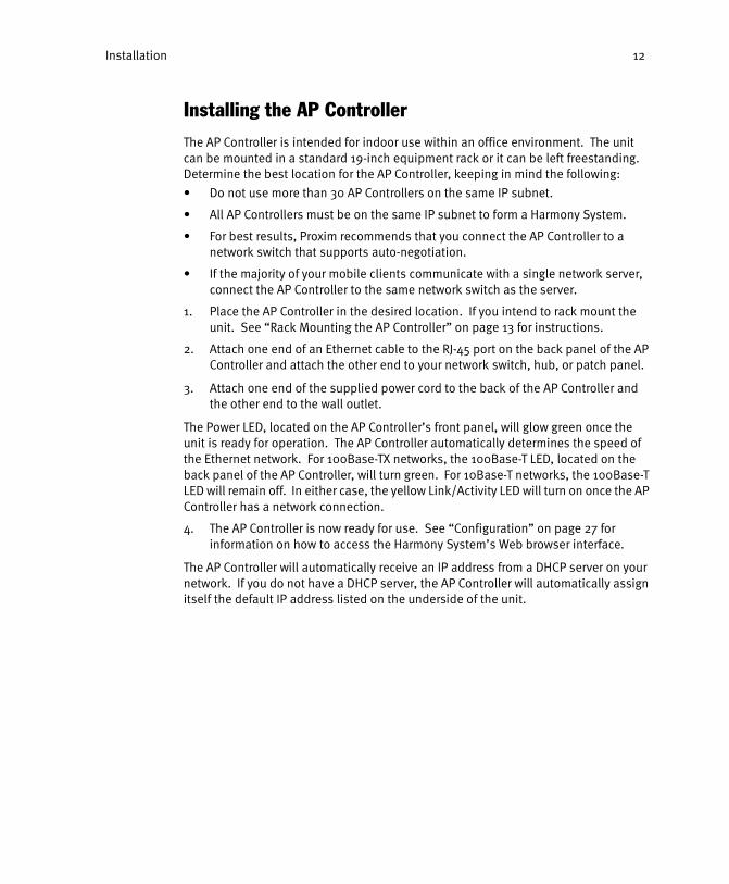
Installing the AP Controller
The AP Controller is intended for indoor use within an office environment. The unit can be mounted in a standard 19-inch equipment rack or it can be left freestanding. Determine the best location for the AP Controller, keeping in mind the following:
• Do not use more than 30 AP Controllers on the same IP subnet.
• All AP Controllers must be on the same IP subnet to form a Harmony System.
• For best results, Proxim recommends that you connect the AP Controller to a network switch that supports auto-negotiation.
• If the majority of your mobile clients communicate with a single network server, connect the AP Controller to the same network switch as the server.
1. Place the AP Controller in the desired location. If you intend to rack mount the unit. See “Rack Mounting the AP Controller” on page 13 for instructions.
2. Attach one end of an Ethernet cable to the RJ-45 port on the back panel of the AP Controller and attach the other end to your network switch, hub, or patch panel.
3. Attach one end of the supplied power cord to the back of the AP Controller and the other end to the wall outlet.
The Power LED, located on the AP Controller’s front panel, will glow green once the unit is ready for operation. The AP Controller automatically determines the speed of the Ethernet network. For 100Base-TX networks, the 100Base-T LED, located on the back panel of the AP Controller, will turn green. For 10Base-T networks, the 100Base-T LED will remain off. In either case, the yellow Link/Activity LED will turn on once the AP Controller has a network connection.
4. The AP Controller is now ready for use. See “Configuration” on page 27 for information on how to access the Harmony System’s Web browser interface.
The AP Controller will automatically receive an IP address from a DHCP server on your network. If you do not have a DHCP server, the AP Controller will automatically assign itself the default IP address listed on the underside of the unit.

Installation 13
Rack Mounting the AP Controller
The Harmony AP Controller is 1U (Unit) high and fits in most standard 19-inch equipment racks. Follow these steps if you intend to rack mount the unit:
Note: Disconnect all cables and remove the self-adhesive pads from the underside of the Harmony AP Controller before attempting to rack mount the unit.
1. Place the Harmony AP Controller right side up on a hard, flat surface with the front of the unit facing towards you.
2. Position the mounting bracket over the mounting holes on one side of the unit, as shown in Figure 3.
Figure 3: Rack Mounting Bracket Assembly
3. Insert the four screws included in the product package and tighten with a screwdriver.
Note: Use only the screws supplied with the mounting brackets. Damage caused to the unit by using incorrect screws is not covered by the warranty.
4. Repeat Steps #2 and 3 for the other side of the unit.
5. Insert the unit into the 19-inch rack and use standard screws and a screwdriver to secure it in place (screws to connect the rack mount bracket to a 19-inch equipment rack are not provided). Ensure that the ventilation holes are not obstructed.

Installation 14
Installing a Harmony 802.11a Access Point
Follow these steps to install the Harmony 802.11a Access Point after installing your Harmony Access Point Controller.
1. Determine the best location for the Harmony 802.11a Access Point. Keep in mind the following considerations:
• The length of the Ethernet cable that connects the Access Point to the network must not exceed 100 meters.
• Try to place the Access Point on a flat, sturdy surface as far from the ground as possible, such as on top of a desk or bookcase, keeping clear of metal obstruc-tions and away from direct sunlight.
• Try to centrally locate the Access Point’s antennas so that it will provide cover-age to all of the mobile devices in the area.
• If using Model 8571 with external antennas:
• Place the Access Point and antennas so that the antennas can be easily connected to the Access Point.
• Use the shortest antenna cable possible; use a longer Ethernet cable if necessary.
• Install the antennas and cabling before proceeding to Step #2.
• You may install the Access Point and the AP Controller on different IP subnets. See “Roaming Across a Router” on page 25 for details.
2. Place the Access Point in the desired location. The Access Point ships with an optional mounting kit. Refer to the Harmony 802.11a Access Point User’s Guide for instructions if you want to mount the unit on a wall or ceiling.
3. Attach one end of an Ethernet cable to the Access Point and attach the other end to the 10/100Base-TX port of a network hub, switch, router, or patch panel.
4. If you are not using the Harmony Power System to supply power to the Access Point or want to connect the Access Point to both the Power System and an AC power source, attach one end of the AC power adapter, included in the product package, to the back of the Access Point and the other end to a power outlet.
Note: Use only the power adapter supplied by Proxim in the product package. Using another power supply may damage the Access Point. If you want to use the Access Point in conjunction with the Harmony Power System, refer to the Harmony Power System User’s Guide for instructions.

Installation 15
All three LEDs on the top of the Access Point will light up when the unit is powered on. Next, the Status LED will turn amber and then solid green to indicate that the unit is operational. In addition, the Link LED on the rear panel will light to indicate that the Access Point has a network connection. The LED is lit green if connected to a 100Base-TX network and lit amber if connected to a 10Base-T network.
Note: If the Status LED remains amber, the Access Point cannot find an AP Control-ler to partner with. Refer to Chapter 9 beginning on page 101 and the Access Point’s User Guide for troubleshooting suggestions.
5. The AP Controller will automatically detect and configure the Access Point over the network. See “Configuration” on page 27 for more information on how to configure an Access Point.
Refer to the Harmony 802.11a Access Point User’s Guide for additional information.

Installation 16
Installing a Harmony 802.11b Access Point
The Harmony 802.11b Access Point can operate with or without an Access Point Controller. The instructions below assume that you intend to use the Harmony 802.11b Access Point with an Access Point Controller.
In order to communicate with an AP Controller, a Harmony 802.11b Access Point’s AP Controller Dependence parameter must be set to either Flexible or Dependent. By default, AP Controller Dependence is set to Flexible. For more information on AP Controller Dependence, refer to the Harmony 802.11b Access Point User’s Guide.
Follow these steps to install the Harmony 802.11b Access Point after installing your Harmony Access Point Controller.
1. Determine the best location for the Harmony 802.11b Access Point. Keep in mind the following considerations:
• The length of the Ethernet cable that connects the Access Point to the network must not exceed 100 meters.
• Try to place the Access Point on a flat, sturdy surface as far from the ground as possible, such as on top of a desk or bookcase, keeping clear of metal obstruc-tions and away from direct sunlight.
• Try to centrally locate the Access Point so that it will provide coverage to all of the mobile devices in the area.
• You may install the Access Point and the AP Controller on different IP subnets. See “Roaming Across a Router” on page 25 for details.
2. Place the Access Point in the desired location. An optional wall mount is available for the Access Point. Refer to the Harmony 802.11b Access Point User’s Guide for more information.
3. Attach one end of an Ethernet cable to the Access Point and attach the other end to the 10Base-T port of a network hub, switch, router, or patch panel.
Note: The Harmony 802.11b Access Point only supports 10Base-T; it does not sup-port 100Base-TX.
4. If you are not using the Harmony Power System to supply power to the Access Point or want to connect the Access Point to both the Power System and an AC power source, attach one end of the AC power adapter, included in the product package, to the back of the Access Point and the other end to a power outlet.
Note: Use only the power adapter supplied by Proxim in the product package. Using another power supply may damage the Access Point. If you want to use the Access Point in conjunction with the Harmony Power System, refer to the Harmony Power System User’s Guide for instructions.

Installation 17
All three LEDs on the top of the Access Point will light up when the unit is powered on. Next, the Status LED will turn amber and then solid green to indicate that the unit is operational. In addition, the green Link LED will turn on to indicate that the Access Point has a network connection.
Note: If the Status LED remains amber or blinks green, the Access Point cannot find an AP Controller to partner with. Refer to Chapter 9 beginning on page 101 and the Access Point’s User Guide for troubleshooting sugges-tions.
5. The AP Controller will automatically detect and configure the Access Point over the network. See “Configuration” on page 27 for more information on how to configure an Access Point.
Refer to the Harmony 802.11b Access Point User’s Guide for additional information.
Installation 18
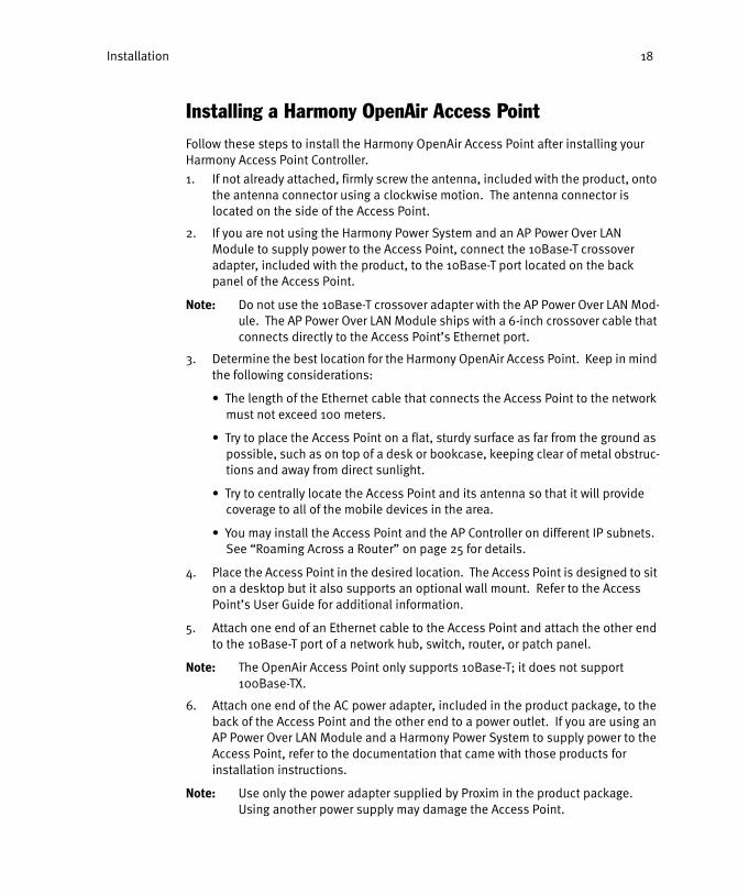
Installing a Harmony OpenAir Access Point
Follow these steps to install the Harmony OpenAir Access Point after installing your Harmony Access Point Controller.
1. If not already attached, firmly screw the antenna, included with the product, onto the antenna connector using a clockwise motion. The antenna connector is located on the side of the Access Point.
2. If you are not using the Harmony Power System and an AP Power Over LAN Module to supply power to the Access Point, connect the 10Base-T crossover adapter, included with the product, to the 10Base-T port located on the back panel of the Access Point.
Note: Do not use the 10Base-T crossover adapter with the AP Power Over LAN Mod-ule. The AP Power Over LAN Module ships with a 6-inch crossover cable that connects directly to the Access Point’s Ethernet port.
3. Determine the best location for the Harmony OpenAir Access Point. Keep in mind the following considerations:
• The length of the Ethernet cable that connects the Access Point to the network must not exceed 100 meters.
• Try to place the Access Point on a flat, sturdy surface as far from the ground as possible, such as on top of a desk or bookcase, keeping clear of metal obstruc-tions and away from direct sunlight.
• Try to centrally locate the Access Point and its antenna so that it will provide coverage to all of the mobile devices in the area.
• You may install the Access Point and the AP Controller on different IP subnets. See “Roaming Across a Router” on page 25 for details.
4. Place the Access Point in the desired location. The Access Point is designed to sit on a desktop but it also supports an optional wall mount. Refer to the Access Point’s User Guide for additional information.
5. Attach one end of an Ethernet cable to the Access Point and attach the other end to the 10Base-T port of a network hub, switch, router, or patch panel.
Note: The OpenAir Access Point only supports 10Base-T; it does not support 100Base-TX.
6. Attach one end of the AC power adapter, included in the product package, to the back of the Access Point and the other end to a power outlet. If you are using an AP Power Over LAN Module and a Harmony Power System to supply power to the Access Point, refer to the documentation that came with those products for installation instructions.
Note: Use only the power adapter supplied by Proxim in the product package. Using another power supply may damage the Access Point.
Installation 19
All three LEDs on the top of the Access Point will light up when the unit is powered on. Next, the Status LED will turn amber and then green to indicate that the unit is operational. In addition, the green Link LED will turn on to indicate that the Access Point has a network connection.
Note: If the Status LED remains amber, the Access Point cannot find an AP Control-ler to partner with. Refer to Chapter 9 beginning on page 101 and the Access Point’s User Guide for troubleshooting suggestions.
7. The AP Controller will automatically detect and configure the Access Point over the network. See “Configuration” on page 27 for more information on how to configure an Access Point.
Refer to the Harmony OpenAir Access Point User’s Guide for additional information.
20
Chapter 3
Wireless Topologies
The Harmony wireless infrastructure family provides network connectivity to mobile clients without the use of wires or cabling. Each Harmony System must include at least one Access Point Controller. The AP Controller centralizes the management and security features of a wireless LAN. In a traditional wireless LAN, each Access Point duplicates this functionality adding additional, unnecessary cost to the network infrastructure. By consolidating these functions into one or more AP Controllers, additional Access Points can easily be added to the network as it grows. As new wireless standards are introduced in the future, additional Access Points may be added at a lower cost than with a traditional Access Point infrastructure.
Each Harmony System also must include at least one Harmony Access Point. The Access Point converts radio signals into Ethernet packets and vice versa. All Access Points that are members of the System obtain their configuration settings from an AP Controller. Harmony 802.11b and OpenAir Access Points communicate exclusively with the AP Controller using a technique known as IP Tunneling. The Harmony 802.11a Access Point support two modes of operation: Tunneled and Managed. In Tunneled mode, the Harmony 802.11a Access Point acts like a Harmony 802.11b or OpenAir Access Point and communicates exclusively with the AP Controller. In Managed mode, the Harmony 802.11a Access Point communicates directly with the Ethernet network but is still centrally managed by the AP Controller.
The number of Access Points per AP Controller varies based on the type of Access Points installed and the operating mode of those Access Points. An AP Controller has a finite capacity to forward and filter packets on the network. Too many Access Points communicating with a single AP Controller may reduce system performance which is determined by the amount of traffic generated by the Ethernet network and the Access Points. For example, an AP Controller can support more 802.11a Access Points in Managed mode than in Tunneled mode because, unlike Access Points in Tunneled mode, Access Points in Managed mode communicate directly with the Ethernet network and packets do not need to be processed by the AP Controller first.
A network subnet can support up to 30 AP Controllers to form a Harmony System that can be managed using a single user interface. The number of clients that an Access Point can support depends on the type of Access Point employed and the amount of information that each client exchanges with the network; the number will vary based on the applications in use and how frequently network information is accessed.
Wireless Topologies 21
Harmony Tunneling Architecture
When an Access Point is operating in Tunneled mode (i.e., all 802.11b and OpenAir Access Points and 802.11a Access Points configured for Tunneled mode), packets exchanged between a mobile client and the Ethernet network pass through both the Access Point and the AP Controller before reaching their final destination.
The following steps describe how a mobile client sends a packet to a network server:
1. A mobile client with a Harmony client adapter installed sends a packet intended for the network server to its Access Point over the wireless medium.
2. The Access Point receives the packet from the mobile client.
3. The Access Point encapsulates the packet from the mobile client into an IP packet. This IP packet is destined for the AP Controller. This encapsulation procedure is known as IP Tunneling.
4. The Access Point sends the IP packet to the AP Controller.
5. The AP Controller receives the IP packet from the Access Point and extracts out the original packet sent by the mobile client.
6. The AP Controller examines the destination address of the original packet and forwards it to the network server.
The steps below describe how a network server sends a packet to a mobile client:
1. The network server sends a packet destined for the mobile client out onto the Ethernet network.
2. The AP Controller examines the packet on the network and recognizes that it is destined for a mobile client.
3. The AP Controller encapsulates the packet from the network server into an IP packet.
4. The AP Controller sends the IP packet to the appropriate Access Point.
5. The Access Point receives the IP packet from the AP Controller and extracts out the original packet sent by the network server.
6. The Access Point sends the original packet to the mobile client over the wireless medium.
The AP Controller determines whether to forward packets from the Ethernet to mobile clients based on its filter settings. In addition, the AP Controller will not forward to an Access Point any directed packets destined for a node that the AP Controller has learned is located on the Ethernet network. (Access Points in Managed mode perform their own filtering based on the filtering settings they receive from the AP Controller.)
Note that on some networks, the communication between AP Controller and Access Points in Tunneled mode can effectively double the amount of traffic related to mobile clients. For example, rather than have an Access Point receive a packet destined for a mobile client directly from the Ethernet, the AP Controller first receives the packet and
Wireless Topologies 22
then forwards it to the Access Point. In this case, there are two packets generated instead of one, which can increase the amount of traffic on the Ethernet backbone.
Given the above, Proxim recommends that you connect the AP Controller and the network server to the same switch to minimize the amount of data that travels on the Ethernet backbone. If the AP Controller and server are connected to the same switch, the switch’s workload will increase but the amount of network traffic will not.
Network With a Single AP Controller
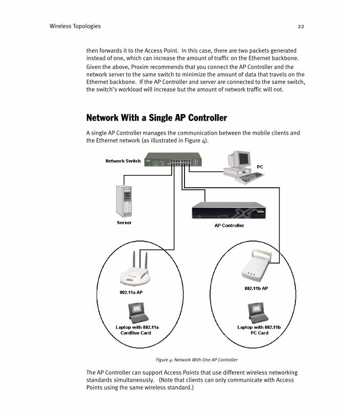
A single AP Controller manages the communication between the mobile clients and the Ethernet network (as illustrated in Figure 4).
Figure 4: Network With One AP Controller
The AP Controller can support Access Points that use different wireless networking standards simultaneously. (Note that clients can only communicate with Access Points using the same wireless standard.)
Wireless Topologies 23
Network With Multiple AP Controllers
All AP Controllers connected to the same IP subnet share the same System parameters, such as filter settings and Authorization Table entries.
Note: All AP Controllers must have the same System ID to share the same System parameters. See “System Parameters” on page 36.
When an Access Point is first connected to the network, it establishes a partnership with one of the AP Controllers. An Access Point and AP Controller do not need to be on the same switch or hub in order to communicate.
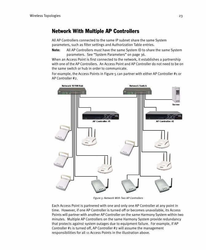
For example, the Access Points in Figure 5 can partner with either AP Controller #1 or AP Controller #2.
Figure 5: Network With Two AP Controllers
Each Access Point is partnered with one and only one AP Controller at any point in time. However, if one AP Controller is turned off or becomes unavailable, its Access Points will partner with another AP Controller on the same Harmony System within two minutes. Multiple AP Controllers on the same Harmony System provide redundancy that protects against system outages due to equipment failure. For example, if AP Controller #1 is turned off, AP Controller #2 will assume the management responsibilities for all 11 Access Points in the illustration above.

Wireless Topologies 24
The AP Controllers communicate with each other over the network to regulate the number of Access Points that are partnered with each AP Controller. As new Access Points are added to the System, they are automatically distributed among the available AP Controllers.
You may also manually configure an Access Point to communicate with a specific AP Controller using the Harmony System’s Web browser interface. All AP Controllers and Access Points that are members of the same Harmony System are included as entries within the Web browser interface.
Roaming Between Access Points
If there are multiple Access Points of the same type (that is, 802.11a, 802.11b, or OpenAir) on the network, then a mobile client may seamlessly roam from one Access Point to another, as shown in Figure 6.
Figure 6: Roaming Between Access Points

Wireless Topologies 25
Each Access Point creates its own wireless coverage area or cell. A mobile device can communicate with a particular Access Point only if it is within the Access Point’s coverage area. If the cells of multiple Access Points overlap, then the mobile client may switch from one Access Point to another as it travels throughout the facility. During the hand-off from one Access Point to another, the mobile client maintains an uninterrupted connection to the network. This is known as roaming. The mobile client determines when it will roam from one Access Point to another based on the radio protocol it follows.
Roaming Across a Router
Traditional wireless LANs do not allow mobile clients to roam between Access Points that are separated by a router. However, a Harmony wireless infrastructure lets mobile clients roam across a router; the client maintains an uninterrupted connection to the network and retains its assigned IP address that is valid on the original subnet.
This feature requires that the network administrator configure the AP Controller with a list of subnets used in the facility so the AP Controller and Access Points can communicate with each other across the router. See “Subnet Table” on page 41 for configuration instructions.
Note: All Harmony 802.11a Access Points installed on remote subnets must oper-ate in Tunneled mode to support roaming across a router.
Roaming Guidelines
• Roaming only occurs between Access Points of the same type. For example, a Harmony 802.11a client adapter can only roam between Harmony 802.11a Access Points.
• The Access Points’ cells must overlap to ensure that there are no gaps in coverage so the roaming client will always have a connection available.
• All Access Points in the same vicinity should use a unique, independent Channel. Access Points that use the same Channel should be installed as far away from each other as possible to reduce potential interference.
• Proxim strongly recommends that you perform a site survey to determine the best location for each Access Point in the facility, as described in Proxim’s technical training class. See Proxim’s web site at http://www.proxim.com/ for more infor-mation.
• An 802.11b Access Point and an OpenAir Access Point installed in the same vicin-ity will interfere with each other (both standards use the same 2.4 GHz frequency range). If you use both 802.11b and OpenAir Access Points on your network, Proxim recommends that you test for potential interference first before deploying the equipment.

Wireless Topologies 26
Networks That Already Use RangeLAN2
Harmony products are designed to coexist with RangeLAN2 installations. Proxim’s RangeLAN2 product line and the Harmony OpenAir products both use the OpenAir standard. Therefore, existing RangeLAN2 devices can interoperate with Harmony OpenAir products. For example, a RangeLAN2 PC Card can communicate with a Harmony OpenAir Access Point, and a Harmony OpenAir PC Card can communicate with a RangeLAN2 Access Point, as illustrated in Figure 7.
Figure 7: A Network Using Harmony and RangeLAN2
In Figure 7, the RangeLAN2 PC Card can roam seamlessly between all three Access Points, even though the Harmony AP Controller does not manage the RangeLAN2 Access Point. Although a Harmony AP Controller cannot manage or configure a RangeLAN2 Access Point, the Harmony System lists the RangeLAN2 Access Points detected on the network within the Web browser interface.
In mixed Harmony/RangeLAN2 networks, Proxim recommends that you manually configure each RangeLAN2 and Harmony OpenAir Access Point with a unique Channel. Also, if mobile devices will use the Harmony products to roam across a router as described earlier this chapter, all RangeLAN2 Access Points must be installed on the same IP subnet as the Harmony AP Controller(s).

27
Chapter 4
Configuration
A Harmony System provides a single user interface to configure and manage all of the AP Controllers and Access Points on your network. Once the Harmony Access Point Controller is installed, access the user interface using a Web browser such as Microsoft Internet Explorer 5 or Netscape Navigator 6.
Accessing the Web Browser Interface
1. Open a Web browser on a network computer.
2. In the Location or Address field, enter the IP address of an AP Controller on the network. For example, if the IP address of an AP Controller is 169.254.172.228, type http://169.254.172.228 and press Enter to access the Web browser interface, shown in the following example.

Configuration 28
On the left-hand side of the screen is the Harmony System’s menu tree. The management options for the selected device appear on the right-hand side of the screen. By default, the Web browser interface will display the Harmony System’s configuration options.
AP Controller’s IP Address
You can configure the AP Controller’s IP address in one of three ways:
• The AP Controller may receive a dynamic IP address from a network DHCP (Dynamic Host Configuration Protocol) server.
• The AP Controller is assigned a default IP address at the factory (169.254.x.y). This IP address is printed on the underside of the unit along with its serial num-ber and physical (or MAC) address. The AP Controller will use this IP address if a DHCP server is not present on the network.
• The AP Controller can be assigned a static IP address via the Web browser inter-face or the local configuration menu, which is accessed using an RS-232 null modem serial cable.
IP Address Assigned by DHCP
If you have a DHCP (Dynamic Host Configuration Protocol) server on the network, then the AP Controller will be automatically assigned an IP address when the unit is powered on.
To determine what IP address has been assigned to the AP Controller, review the IP address assignment list generated by the DHCP server. The DHCP server should provide a list of physical addresses and the corresponding IP addresses that it has assigned to these devices. Locate the AP Controller’s physical address on the list to identify its assigned IP address.
Note: The AP Controller’s physical address is listed on the underside of the unit along with its serial number and default IP address. The physical address is typically written as six pairs of two hexadecimal digits separated by colons (for example, 00:20:A6:34:00:12).
Once you have identified the AP Controller’s IP address, enter this address in a Web browser’s Location or Address field on a network computer to access the Harmony System’s Web browser interface.

Configuration 29
Default IP Address
If your network does not include a DHCP server, then the AP Controller will use the default IP address assigned at the factory. The default IP address is listed on the underside of the unit along with the AP Controller’s serial number and physical address. The AP Controller’s default IP address is in the 169.254.0.0 network.
If the AP Controller is using its default IP address, then you must configure a network computer with a unique IP address in the 169.254.0.0 network in order to access the Web browser interface.
For example, if the AP Controller’s default IP address is 169.254.34.54, then configure one of the network computers with an IP address of 169.254.0.1 and a subnet mask of 255.255.0.0 (assuming that 169.254.0.1 is not already assigned to another network device). If prompted, restart the network computer for the new IP address to take effect. Once the network computer has restarted, open a web browser and type the IP address of the AP Controller in the Location or Address field and press Enter to access the Web browser interface.
Static IP Address
The AP Controller also accepts a static IP address. You may manually configure the IP address, subnet mask, and default gateway used by the AP Controller within either the Web browser interface or the local configuration menu.
Use either the AP Controller’s default IP address or dynamically assigned IP address to access the Web browser interface. To access the local (out-of-band) configuration menu, follow these steps:
1. Turn on the AP Controller, if the unit is not powered up already.
2. Connect one end of a null modem cable to the serial port on the back of the AP Controller and the other end to a serial port on a PC.
Note: A null modem cable is an RS-232 serial cable that has the transmit and receive pins crossed. Most electronic stores sell null modem cables.
3. Open a terminal emulation program, such as HyperTerminal, and create a session using the following settings:
Connect: .............................Direct to COM port # (use the COM port numberthat corresponds to the port that the cable is connected to, typically COM1 or COM2)
Baud Rate: ..........................9600Data bits: ............................8Stop bits: ............................1Parity: .................................NoneFlow Control: .......................None

Configuration 30
4. Press Enter to call up the main menu, shown below.
5. Select the DHCP option.
6. Disable DHCP.
7. Select the Static TCP/IP Settings option from the main menu.
8. Select the Static IP Address option and enter an IP address.
9. Select the Static Subnet Mask option and enter a subnet mask.
10. Select the Static Default Gateway Address option and enter a default gateway address.
11. Press ESC to return to the main menu.
12. Configure a Browser User Name, if desired.
13. Configure a Browser Password, if desired.
Note: The Browser User Name and Password can also be configured from within the Web browser interface.
14. Close the terminal session.
15. Reset the Access Point Controller for these changes to take effect.

Configuration 31
Access Point Configuration
All Harmony Access Points are configured automatically by the AP Controller or manually using the Web browser interface.
Note: An AP Controller cannot configure a Harmony 802.11b Access Point whose AP Controller Dependence parameter is set to Independent.
When an Access Point is first connected to the Ethernet network, it sends out a DHCP request. If there is a DHCP server on the network, it will automatically assign the Access Point an IP address. If you do not have a DHCP server on the network, the Access Point will use its default 169.254.x.y IP address, which is printed on the underside of the unit.
Once the Access Point has an IP address assignment, it sends out a request to the available AP Controllers on the network. One of the AP Controllers responds to this request and automatically configures the Access Point for operation on the network.
The AP Controller automatically assigns the Access Point a radio Channel and configures the other networking parameters using the AP Defaults settings.
Once configured, a new Access Point should automatically appear as an entry in the Web browser interface.
Alternatively, you can manually add a new Access Point to the Harmony System from within the Web browser interface. See “Manually Adding a New Access Point” on page 31.
Note: If you assign the AP Controller a static IP address and your network does not contain a DHCP server, Harmony Access Points will not be automatically rec-ognized and configured at boot-up. You must manually add each Access Point to the Harmony System and specify an IP address for the Access Point that is valid on the subnet to which it is attached.
Refer to Chapter 5 and the user’s guide that shipped with the Access Point for information on the Access Point’s configuration parameters.
Also, if you plan to install the AP Controller and an Access Point on different IP subnets, see “Subnet Table” on page 41 for important configuration information.
Manually Adding a New Access Point
You may need to manually add a new Access Point if one of the following apply:
• You disabled the Allow New APs to Be Added Automatically parameter.
• You have assigned a static IP address to the System’s AP Controller(s) and you do not have a DHCP server on the network.
• An Access Point is not automatically detected by the Harmony System when you connect it to the network.
Note: If you have assigned the AP Controller(s) a static IP address and the network does not contain a DHCP server, then you must manually add each new Access Point to the Harmony System.

Configuration 32
Follow these steps to add an Access Point:
1. Install the Access Point as described in Chapter 2.
Note: The Access Point’s Status LED will remain amber or blink green if it is not automatically added to the Harmony System.
2. Open the Web browser interface.
3. Click the ADD AP button.
4. Enter an AP Name for the Access Point.
5. Enter the Access Point’s Physical Address, which is located on the underside of the unit. Use colons to separate each pair of hexadecimal digits. (For example, enter 00:20:A6:28:BB:AD, as shown in the following example.)
6. Select the AP Type (OpenAir, 802.11b, or 802.11a) from the drop-down menu.
7. Click the ADD AP button.
8. Click the Network tab in the upper left-hand corner of the browser screen to return to the main menu.
9. Expand the Unregistered APs folder on the left-hand side of the browser screen.
10. Click the icon that corresponds to the AP you recently added, as shown in the following example.
Configuration 33
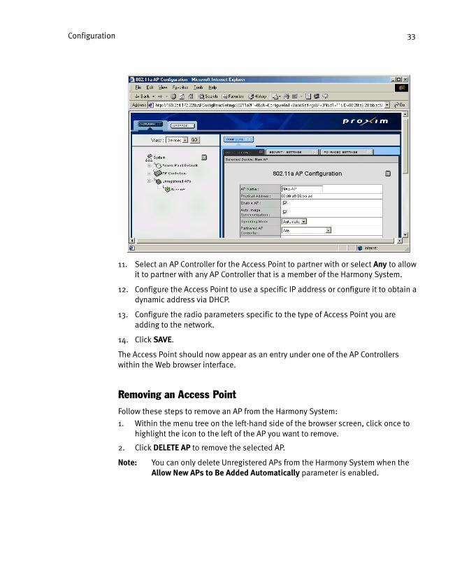
11. Select an AP Controller for the Access Point to partner with or select Any to allow it to partner with any AP Controller that is a member of the Harmony System.
12. Configure the Access Point to use a specific IP address or configure it to obtain a dynamic address via DHCP.
13. Configure the radio parameters specific to the type of Access Point you are adding to the network.
14. Click SAVE.
The Access Point should now appear as an entry under one of the AP Controllers within the Web browser interface.
Removing an Access Point
Follow these steps to remove an AP from the Harmony System:
1. Within the menu tree on the left-hand side of the browser screen, click once to highlight the icon to the left of the AP you want to remove.
2. Click DELETE AP to remove the selected AP.
Note: You can only delete Unregistered APs from the Harmony System when the Allow New APs to Be Added Automatically parameter is enabled.

Configuration 34
Upgrading an Access Point
The System’s Web browser interface provides a utility to upgrade specific Access Points that may have been unavailable when the rest of the System was upgraded.
Note: You do not need to manually upgrade Access Points if you have the Auto Image Synchronization feature enabled. See “Configuration Parameters” on page 35.
Follow these steps to upgrade a new Access Point using a firmware version that has already been uploaded to the Harmony System:
1. Click the Upgrade tab on the main Web browser screen.
2. Click Upgrade using images on this APC.
3. Click once to highlight the device you want to upgrade.
4. To select multiple devices to upgrade, hold down the CTRL key while clicking the entry for each unit. (Click the CLEAR SELECTIONS button if you decide not to upgrade the selected devices or if you want to begin the selection process again.)
5. Click UPGRADE.
6. The Harmony System will automatically upgrade the selected devices. If you select an Unregistered AP, the Harmony System will automatically upgrade the Access Point the next time the Access Point is connected to the network and rebooted.
Note: OpenAir Access Point users: see “Note to OpenAir Access Point Users” on page 103 for important information before attempting to upgrade an OpenAir Access Point.

35
Chapter 5
Configuration Parameters
The Network Menu Tree on the left-hand side of the browser screen supports two views: Devices and Groups. In the Devices view, a user can configure and/or monitor all of the Harmony System’s devices, including AP Controllers, Access Points, and Stations (mobile clients). In the Groups view, a user can manage groups of Access Points that share a common configuration.
This chapter describes the Harmony parameters that can be configured within the Web browser interface’s Devices view, which is the default setting. See “Viewing AP Groups” on page 90 for information on Groups view.
In the Devices view, the Network Menu Tree displays a number of device headings, including System, AP Controllers (APCs), Access Points (APs), Access Point Defaults, Unregistered APs, RangeLAN2 Access Points, and Stations.
Note: The Web browser interface provides only status and statistics for Stations and only status information for RangeLAN2 APs.

Configuration Parameters 36
System Parameters
System refers to the entire Harmony infrastructure composed of AP Controllers and Access Points. The System Parameters are global settings that apply to all of the AP Controllers located on a single IP subnet (assuming that all AP Controllers have the same System ID). A change to one of the System Parameters will impact all devices on the Harmony wireless network.
Note: To form a Harmony System that uses the same System Parameters, all AP Controllers must be installed on the same IP subnet and must be configured with the same System ID.
If your network configuration requires that the AP Controllers use different System Parameters (for example, you may want different AP Controllers to use different Filter settings), then configure the AP Controllers with different System IDs to create multiple Harmony Systems. Each Harmony System will have its own Web browser interface.
Note: If the AP Controllers on one System are turned off, the AP Controllers on another Harmony System will NOT assume the management responsibilities for the Access Points that were partnered with the disabled AP Controllers.
Follow these steps to configure one of the System Parameters:
1. Click the System icon on the left-hand side of the Web browser screen to view the System’s Configure screen, shown below.
2. Select the tab that corresponds to the System Parameter that you want to change. The following sections describe the configuration options in detail.

Configuration Parameters 37
System Access
The System Access parameter changes the Web browser interface’s User Name and Password.
These parameters are equivalent to the Browser User Name and Browser Password settings found in the local configuration menu.
A user is prompted to enter this User Name and Password each time he/she attempts to access the Web browser interface. In addition, the Web browser interface prompts a user to reenter the User Name and Password if the interface is left idle for more than five minutes.
The User Name cannot exceed 32 characters. The Password cannot exceed 10 characters. Both the User Name and Password are case sensitive. By default, the User Name and Password are blank, and a user does not need to provide a User Name or Password to access the Web browser interface.
When configuring a User Name and Password, note that the Password must be entered twice. Also, you must click SAVE for these changes to take effect.
Note: There can only be one active Web browser session when a User Name and Password are configured.
Filters
The System Filters let the user customize the type of traffic that is forwarded from the Ethernet network to the mobile clients on the Harmony network. None of these filters affect traffic flowing from the mobile clients to the Ethernet backbone.
The filters are divided into five headings: Protocol Type Filters, Physical Address Multicast Filter, Address Resolution Protocol, IPX Broadcast Filters, and Broadcast Bandwidth Allocation.
Note: Click SAVE at the bottom of the screen to implement any changes that you make to these settings.
Protocol Type FiltersThe Protocol Type Filters prevent directed traffic of a particular protocol type from being forwarded from the Ethernet to mobile clients on the Harmony network. These filters only affect unicast packets that are destined for a single node.
The Web browser interface provides a box for each protocol entry. When the box is checked, the Harmony System filters out the specified protocol. The packets that conform to a filtered protocol will not be forwarded to mobile clients.
Note: Do NOT place a check mark next to a Protocol Type Filter that you know mobile clients will need to receive. For example, if you use TCP/IP as a pro-tocol on your mobile clients, do not filter IP/ARP traffic.

Configuration Parameters 38
The Protocol Type Filters are:
• IP/ARP: When set to filtering, the Harmony System will not forward TCP/IP pack-ets to mobile clients.
• IPX: When set to filtering, the Harmony System will not forward IPX packets to mobile clients. IPX is typically used by Novell networks.
• NetBEUI: When set to filtering, the Harmony System will not forward NetBEUI packets to mobile clients. NetBEUI is typically used by IBM LAN Manager, Win-dows for Workgroups, and some Windows 9x/NT/2000 networks.
• DECNet: When set to filtering, the Harmony System will not forward DECNet pack-ets to mobile clients.
• AppleTalk: When set to filtering, the Harmony System will not forward AppleTalk packets to mobile clients. AppleTalk is typically used by Macintosh computers.
• Other: When set to filtering, the Harmony System will not forward any unicast packet that does not conform to one of the above protocols.
Multicast Address FilterSome hardware technologies support a form of packet delivery known as multicasting. While a unicast packet is destined for only one node on the network, a multicast packet is destined for multiple nodes. A broadcast packet is a type of multicast packet that is destined for all nodes on the network. Typically, a group of devices are configured to recognize and accept a particular multicast address. This allows multiple devices to receive the same packet, and a multicast packet is more efficient than a broadcast packet because only those devices configured to receive the packet will accept it. For Ethernet networks, a multicast address is defined as a physical address in which the last bit in the first octet is set to 1. Typically, this is represented in hexadecimal form as 01:00:00:00:00:00. However, any physical address whose second digit in the first octet is a 1, 3, 5, 7, 9, B, D, or F has the last bit set to 1 and is a multicast address.
When the Multicast Filter option is checked, the Harmony System will filter or forward multicast packets to mobile clients based on the range of multicast addresses specified by the Multicast Address and Multicast Mask. If the destination address of a multicast packet is not within the range of physical addresses defined by the Multicast Address and Multicast Mask, then the Harmony System will not forward the packet to mobile clients.

Configuration Parameters 39
ARP FilterThe TCP/IP Internet Protocol Suite uses a method known as ARP (Address Resolution Protocol) to match a device’s physical address with its assigned IP address. ARP broadcast packets are sent out to all members of the network and the device whose IP address is contained in the packet responds to the sender.
The Harmony System will forward ARP broadcasts to mobile clients by default, even if the packet is not meant for one of the mobile clients. As the number of nodes on a network backbone increases, so does the number of ARP broadcasts that are forwarded to the mobile clients. Many of these ARP broadcasts are unnecessary and can consume valuable bandwidth. On some networks, there are so many ARP broadcasts that the performance of the Harmony network can degrade due to the amount of bandwidth consumed by these messages.
When the ARP Filter option is checked, the Harmony System will filter or forward ARP broadcasts to mobile clients based on the IP network specified by the Network IP Address and Network Subnet Mask. These parameters define a range of IP addresses that are assigned to the mobile clients.
If the address contained within an ARP broadcast is not within the range of addresses defined by the Network IP Address and Network Subnet Mask, then the Harmony System will not forward the packet to mobile clients.
IPX Broadcast FiltersThe IPX Broadcast Filters prevent IPX broadcasts of the specified types from being forwarded from the Ethernet network to mobile clients on the Harmony network.
Since RIP, SAP, and LSP broadcasts are of interest to routers and not end stations, these filters can typically be turned on, saving valuable bandwidth. RIP stands for Routing Information Protocol. SAP stands for Service Advertising Protocol. LSP stands for Link State Protocol. These three broadcast types are filtered by default.
Broadcast Bandwidth AllocationBroadcast Bandwidth Allocation lets you specify the maximum percentage of the system bandwidth that can be allocated for broadcast traffic. There may be cases when you want to limit broadcast traffic. As an example, to prioritize directed packets, you might want to reserve radio bandwidth for directed packets by setting this limit to less than 100%. By default, the Broadcast Bandwidth Allocation is set to 80%.
Configuration Parameters 40
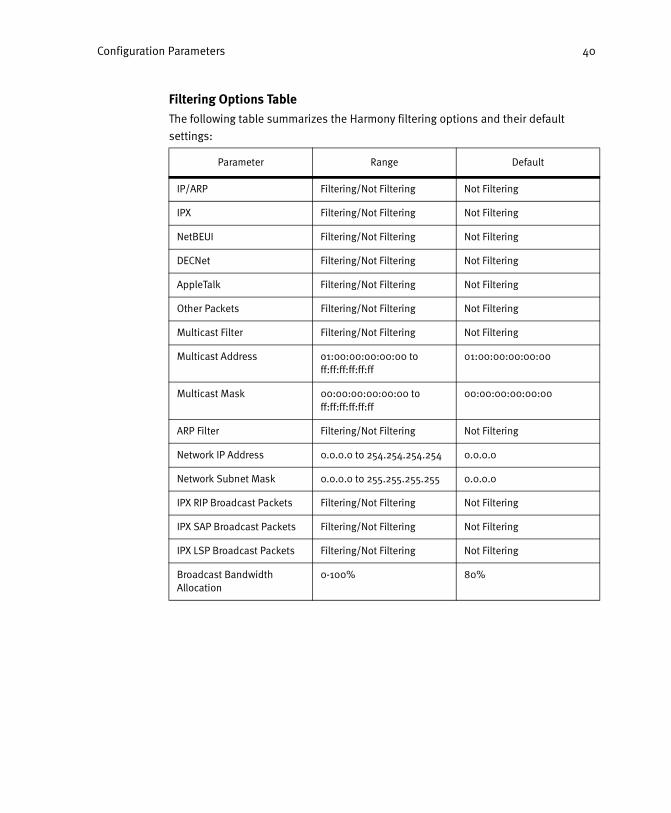
Filtering Options TableThe following table summarizes the Harmony filtering options and their default
settings:
Parameter Range Default
IP/ARP Filtering/Not Filtering Not Filtering
IPX Filtering/Not Filtering Not Filtering
NetBEUI Filtering/Not Filtering Not Filtering
DECNet Filtering/Not Filtering Not Filtering
AppleTalk Filtering/Not Filtering Not Filtering
Other Packets Filtering/Not Filtering Not Filtering
Multicast Filter Filtering/Not Filtering Not Filtering
Multicast Address o1:00:00:00:00:00 to ff:ff:ff:ff:ff:ff
01:00:00:00:00:00
Multicast Mask 00:00:00:00:00:00 to ff:ff:ff:ff:ff:ff
00:00:00:00:00:00
ARP Filter Filtering/Not Filtering Not Filtering
Network IP Address 0.0.0.0 to 254.254.254.254 0.0.0.0
Network Subnet Mask 0.0.0.0 to 255.255.255.255 0.0.0.0
IPX RIP Broadcast Packets Filtering/Not Filtering Not Filtering
IPX SAP Broadcast Packets Filtering/Not Filtering Not Filtering
IPX LSP Broadcast Packets Filtering/Not Filtering Not Filtering
Broadcast Bandwidth Allocation
0-100% 80%

Configuration Parameters 41
Subnet Table
Unlike traditional wireless infrastructures, Harmony allows roaming across routers. Mobile clients may roam between Access Points located on different IP networks, as shown in Figure 8. Figure 8 includes sample IP addresses to illustrate this concept.
Figure 8: Roaming Between Access Points on Different IP Subnets
To support roaming across subnets, the Access Points located on remote subnets must be partnered with an AP Controller on the local subnet. However, by default an Access Point on a remote subnet cannot partner with an AP Controller; the router that separates the subnets will not forward the Access Point’s broadcast packets (sent at boot-up) to the AP Controller. To work around this limitation, the System periodically sends out a local broadcast packet to each of the IP subnets listed in its Subnet Table to find Access Points. If the router that separates the subnets does not pass local broadcast traffic, then you can configure the remote Access Point’s IP address in the Subnet Table and the System will periodically send out a packet to find the specific Access Point. The Subnet Table can hold a maximum of 32 entries; for best results, remove any unused entries and use the smallest number of entries possible.
Note: The AP Controller must receive a dynamic IP address from a DHCP server or use a static IP address in order to support roaming across subnets. The AP Controller cannot use its default 169.254.x.y address with this feature.
Configuration Parameters 42
Follow these steps to configure an Access Point on a remote subnet:
1. Click the Subnet Table tab within the System’s Configure screen.
2. In the Subnet field, enter the remote subnet to which you will connect an Access Point. For example, if the local subnet is 10.0.0.0 with a 255.0.0.0 subnet mask, and the remote network is 11.0.0.0 with a 255.0.0.0 subnet mask, enter 11.0.0.0 in the field provided. (If the router that separates the two subnets does not pass local broadcast traffic, then enter the remote Access Point’s IP address in the Subnet field.)
3. In the Mask field, enter the remote subnet’s mask. For example, if the remote network is 11.0.0.0 with a 255.0.0.0 subnet mask, enter 255.0.0.0. (If the router that separates the two subnets does not pass local broadcast traffic, then enter 255.255.255.255 in the Mask field.)
4. In the Gateway field, enter the IP address of the local gateway that the AP Controller will use to communicate with the remote subnet. For example, if the local IP address of the gateway that communicates with the 11.0.0.0 network is 10.0.0.254, enter 10.0.0.254 in the field provided.
5. Click ADD and the addresses you entered in Steps #2 through 4 will be added to the Subnet Table.
6. If not already installed, connect the Access Point to the remote subnet.
7. The AP Controller will automatically detect and configure the Access Point installed in Step #5 above. This process may take up to one minute.
Note: All Harmony 802.11a Access Points installed on remote subnets must oper-ate in Tunneled mode to support roaming across subnets.
Assigning IP Addresses to Access Points on Remote SubnetsAn Access Point located on a remote subnet must be assigned a valid IP address for that subnet. For example, if the local network that contains the AP Controller is the 10.0.0.0 network and the remote network is 11.0.0.0, then the remote Access Point must be assigned a unique address on the 11.0.0.0 network to operate correctly.
If the remote subnet contains a DHCP server, then the DHCP server will assign the Access Point an IP address valid on that network. If the remote subnet does not contain a DHCP server, use the Web browser interface to specify an IP address for the Access Point that is valid on the remote subnet. However, the router that separates the two networks must be configured with an IP helper to allow the AP Controller to assign a specific IP address to a remote Access Point.
Removing an Entry from the Subnet Table1. Click once to highlight the entry you want to remove. To select multiple entries to
remove, hold down the CTRL key while clicking each entry.
2. Click REMOVE SELECTED ENTRIES.

Configuration Parameters 43
Authorization Table
The Authorization Table prohibits unauthorized access to the Ethernet network via the wireless LAN. The Authorization Table contains a list of mobile clients that can either be granted or denied access to the Ethernet LAN through the Harmony network based on a client’s physical address. (For example, if a Harmony OpenAir PC Card is missing, you can use to the Authorization Table to prevent an unauthorized individual from accessing the network with the stolen card.)
The Authorization Table can hold up to 10,000 entries. All AP Controllers on a Harmony System use the same Authorization Table. The Authorization Table has three states: Unused, Allow Access, and Deny Access.
• Unused: The AP Controller does not refer to the Authorization Table before allow-ing a mobile client to communicate with the network.
• Allow Access: The AP Controller will only allow a mobile client to communicate with the network if the client’s physical address is listed within the Authorization Table.
• Deny Access: The AP Controller will not allow a mobile client to communicate with the network if the client’s physical address is listed within the Authorization Table.
To change the Authorization Table Usage, select a new setting from the drop-down menu and click CHANGE USAGE. By default, the Authorization Table is set to Unused.
Adding a Station to the Authorization Table1. Enter the MAC address of the wireless LAN adapter installed in the mobile client
in the box labeled Physical Address.
The physical address or MAC address is a 48-bit unique identifier assigned to each networking device. It is expressed as 6 pairs of two hexadecimal digits separated by colons. When adding a Station to the Authorization Table, use colons to separate each pair of hexadecimal digits. (For example, 00:20:A6:00:66:76.)
2. Click ADD WIRELESS STATION. The Station’s physical address should now appear in the Wireless Station List.
Removing a Station from the Authorization Table1. Click once to highlight the entry you want to remove. (To select multiple entries
to remove, hold down the CTRL key while clicking each entry.)
2. Click REMOVE ITEMS.
You can also click REMOVE ALL to delete all of the entries in the Authorization Table.

Configuration Parameters 44
Importing Physical Addresses from a Text FileTo add multiple Stations to the Authorization Table at the same time, you can import a text file that contains all of the Stations’ physical addresses. The text file must list each physical address as six pairs of two hexadecimal digits separated by colons.
Use a text program such as Notepad to create the text file. The text file should have a “.txt” extension. Each physical address must appear on its own line (that is, the addresses must be separated by a carriage return). The first line of the text file must read “#AUTHORIZATION_TABLE.” The following example illustrates the format required for the text file:
#AUTHORIZATION_TABLE00:20:A6:56:34:E400:60:B3:67:01:8200:60:B3:67:00:3E00:20:A6:45:4D:23
Once you have a text file that contains the addresses you want to include in the Authorization Table, follow these steps:
1. Open the System’s Authorization Table Configuration screen.
2. Do one of the following:
• Enter the location of the text file in the field labeled Wireless Stations File.
• Click Browse to search for the file on the computer or on the network.
3. Click REPLACE TABLE.
The physical addresses contained in the text file will be added to the Authorization Table, as shown in the following example.
This will overwrite any previous entries contained within the Authorization Table.

Configuration Parameters 45
Advanced
You may configure the following parameters within the Advanced System Configuration screen.
Repeating EnabledThe Repeating Enabled parameter determines whether mobile clients can communicate with each other. An AP Controller must repeat packets between Access Points to allow two mobile clients to communicate with each other.
When set to True, the AP Controllers on the Harmony System will repeat packets between Access Points. When set to False, the AP Controllers will not repeat packets between Access Points, prohibiting communication between mobile clients.
By default, Repeating Enabled is set to False; this setting can help preserve radio bandwidth since fewer packets will be forwarded unnecessarily to mobile clients. However, if the mobile clients on your network need to communicate with each other, then configure Repeating Enabled to True.
Allow New APs to Be Added AutomaticallyBy default, the Harmony System automatically adds new Access Points to the network. If you do not want new Access Points added automatically, you can change the Allow New APs to Be Added Automatically option to False.
OpenAir ARP Cache EnabledThis parameter refers to OpenAir products only. OpenAir wireless clients support a power management mode known as doze mode. An OpenAir client in doze mode wakes up to receive directed packets (i.e., unicast packets) only; it does not wake up to receive broadcast or multicast packets. Therefore, a dozing client will not wake up to receive ARP (Address Resolution Protocol) broadcast packets, which are a component of TCP/IP communication.
When the OpenAir ARP Cache Enabled parameter is set to True, the Harmony System maintains a table of OpenAir clients and their IP addresses. The System adds the client’s information to the table the first time that the client transmits a packet to the Ethernet network. The ARP Cache Table can hold up to 1000 entries that remain in the table unless the table size is exceeded (old, unused entries are replaced first) or the Harmony System is powered off. If the System receives an ARP broadcast that contains the IP address of a dozing OpenAir client, it converts the ARP broadcast into a directed packet that the dozing client will wake up to receive (this assumes that the Harmony System already has an entry for the dozing client in its ARP Cache Table).
When the OpenAir ARP Cache Enabled parameter is set to False, the Harmony System does not maintain the ARP Cache Table and does not convert ARP broadcasts into directed packets for dozing clients. By default, OpenAir ARP Cache Enabled is set to False. You should set this parameter to True if you have OpenAir clients on your network that use power management to extend battery life.
Configuration Parameters 46
Security (Wired Server Address Filter)
Click the Security tab to view the configuration screen for the Wired Server Address Filter.
The Wired Server Address Filter prevents mobile clients from communicating over TCP/IP with any Ethernet node other than those that appear within the Server List. This feature protects Ethernet resources from unauthorized access by mobile clients. For example, if your network has a VPN server to authenticate users, you can force all wireless traffic to the VPN server by entering its IP address in the Server List.
When the Wired Server Address Filter is enabled, the Harmony System will not forward to the Ethernet network any TCP/IP packet from a mobile client not destined for one of the IP addresses in the Server List. In addition, mobile clients associated with different Access Points will not be able to communicate with each other, even if the Repeating Enabled parameter is set to True.
The Server List can hold up to 32 entries. All AP Controllers on a Harmony System use the same Server List.
Wired Server Filter UsageYou may either enable or disable the Wired Server Filter. To change the Wired Server Filter Usage, select a new setting from the drop-down menu and click CHANGE USAGE. By default, the Wired Server Filter is Disabled.
Adding a Wired Server to the Server List1. Enter the wired server’s IP address in the box labeled IP Address. When adding a
server to the Server List, use standard dotted decimal notation for the IP address. For example, if the server’s IP address is 10.0.0.1, enter 10.0.0.1 in the field provided.
2. Click ADD WIRED SERVER.
The wired server’s IP address should now appear in the Server List.
Removing an Entry from the Server List1. Click once to highlight the entry you want to remove.
2. Click REMOVE SERVER.
Alternatively, click REMOVE ALL to clear all entries from the Server List.

Configuration Parameters 47
SNMP
In addition to the Web browser interface, you can also monitor a Harmony AP Controller over the network using an SNMP (Simple Network Management Protocol) manager. The AP Controller supports the standard SNMP management base, MIB-II (RFC 1213). All AP Controllers within a Harmony System share the same SNMP configuration settings.
You can configure and view the following SNMP settings for the Harmony System:
• Enable SNMP: Place a check mark in the box provided to let an SNMP manager monitor the AP Controllers in a Harmony System. When disabled, an SNMP man-ager cannot communicate with the System’s AP Controllers. By default, support for SNMP is enabled.
• Read-Only SNMP Community: This parameter specifies a community supported by the Harmony System. Actions permitted by this community are read-only (GET and GET-NEXT). SET attempts using this community will result in rejection of the attempt with a general error response and the generation of an authentication trap (if enabled). By default, this community is set to “public.”
• Read-Only SNMP Manager IP Address: This setting specifies the IP address of the SNMP manager which is permitted to use the Read-Only SNMP Community. An address of 0.0.0.0 indicates any manager may use this community.
• Read-Write SNMP Community: This parameter specifies a community supported by the Harmony System. Actions permitted by this community are read-write (GET, GET-NEXT, and SET). By default, the community is set to “private.”
• Read-Write SNMP Manager IP Address: This setting specifies the IP address of the SNMP manager which is permitted to use the Read-Write SNMP Community. An address of 0.0.0.0 indicates any manager may use the community.
• SNMP Trap Community: This parameter specifies the community that will be used by the Harmony System when generating Trap-PDUs (Protocol Data Units) to send to an SNMP manager. By default, the community is set to “trap.”
• Trap Target Address: This parameter specifies the IP address of the SNMP man-ager to which the System’s AP Controllers will send Trap PDUs (Protocol Data Units). A value of 0.0.0.0 disables trap generation.
• Enable Authentication Traps: Place a check mark in the box provided to configure the Harmony System to send a trap to the Trap Target Address whenever a user attempts to manage an AP Controller via SNMP from an invalid community. By default, Authentication Traps are enabled.
SNMP Supported TrapsA device that is managed via SNMP occasionally sends unsolicited messages to the SNMP manager; these messages are known as traps. A trap is typically generated in response to a specific event. For example, during boot up, an SNMP-managed device sends a Cold Start trap to the SNMP manager.

Configuration Parameters 48
The following traps are supported by the Harmony System’s AP Controllers and are sent to the configured Trap Target Address when they occur:
• Cold Start: An AP Controller generates this trap when the unit is powered on or rebooted.
• Link Up: An AP Controller generates this trap when its Ethernet port initializes. Generally, a Link Up trap is sent following a reboot of an AP Controller.
Note: The MIB-II standard supports a Link Down trap as well as a Link Up trap. However, since an AP Controller has only one Ethernet interface, an AP Con-troller cannot send a Link Down trap if its Ethernet interface fails to initialize or becomes unavailable.
• Authentication/Authorization: The Harmony System generates this trap when a user attempts to manage an AP Controller via SNMP from an invalid community.
User Database Configuration
The Harmony System supports an optional security feature known as the Harmony Security Protocol. This protocol automates encryption management, assigning a unique and dynamic WEP Key to each user. The User Database is used in conjunction with this protocol to authenticate users on the wireless network; it contains the list of users that can access the network when the Harmony Security Protocol is enabled. At this time, the Harmony Security Protocol is only available with Harmony 802.11a Access Points. See “Harmony Security Protocol” on page 58 for additional information.
Each Harmony user has a User Name and Password that are entered into the database by the network administrator within the User Database Configuration screen. Each user entry in the User Database table lists the User Name, Last Name, and First Name (the Password is not displayed). Note that the User Database table will not appear if the database has no entries. The User Database can hold up to 4096 entries.
The following sections provide step-by-step instructions for how to add, edit, and manage user information.
Note: To make changes that affect the entire database (such as removing all users from the database), click the link provided on the User Database Configura-tion page to access the advanced configuration parameters.
Add UserFollow these steps to add a new user to the User Database:
1. Find the table located directly above the ADD A NEW USER button within the User Database Configuration screen.
2. Enter a user name in the User Name field. The user name can be up to 20 characters.
3. Enter the user’s last name in the Last Name field. This field supports up to 20 characters.
Configuration Parameters 49
4. Enter the user’s first name in the First Name field. This field supports up to 20 characters.
5. Enter a password for the user within the Password field. The password can be up to 32 characters; the password you enter will appear as a series of stars (“*”).
6. Enter the password a second time in the Confirm Password field.
7. Remove the check mark from the Enable box to prevent the user from having immediate access to the network once the user’s entry has been added to the User Database. New entries are enabled by default (i.e., the user can access the network once his or her entry has been added to the table).
8. Click ADD A NEW USER to create an entry in the User Database using the information you entered.
Change a User’s PasswordFollow these steps to change a configured user’s password:
1. Find the table located directly above the CHANGE THIS USER’S PASSWORD button within the User Database Configuration screen.
2. Enter the user name for the user whose password you want to change in the User Name field.
3. Enter the new password in the New Password field. The password can be up to 32 characters.
4. Enter the new password a second time in the Confirm New Password field.
5. Click CHANGE THIS USER’S PASSWORD so that the new password will take effect.
Note: The passwords you enter will appear as a series of stars (“*”).
Remove an Entry from the User DatabaseFollow these steps to remove one or more entries from the User Database:
1. Place a check mark in the Remove box for each entry that you want to remove.
2. Click SAVE to remove the entries.
Enable an Entry in the User DatabaseA user’s entry in the User Database must be enabled before the user can communicate with a Harmony Access Point that has the Harmony Security Protocol enabled. If you did not enable a user when you added him or her to the database, follow these steps to enable one or more entries in the User Database:
1. Place a check mark in the Enable box for each entry that you want to enable.
2. Click SAVE.
Configuration Parameters 50
Disable an Entry in the User DatabaseA user’s entry in the User Database must be enabled before the user can communicate with a Harmony Access Point that has the Harmony Security Protocol enabled. Follow these steps to disable one or more entries in the User Database (to prevent the user from accessing the network):
1. Remove the check mark from the Enable box for each entry that you want to disable.
2. Click SAVE.
Change a User’s First Name or Last NameFollow these steps to change a user’s First Name or Last Name:
1. Locate the entry within the User Database that you want to change.
2. Edit the user’s last name within the Last Name field, if desired. The last name can be up to 20 characters.
3. Edit the user’s first name within the First Name field, if desired. The first name can be up to 20 characters.
4. Click SAVE for your changes to take effect.
Change a User NameTo change a User Name, remove the user’s existing entry in the User Database (see “Remove an Entry from the User Database” on page 49) and then create another entry for the user using the new User Name (see “Add User” on page 48).

Configuration Parameters 51
AP Controller Parameters
You can configure each AP Controller with its own network settings.
1. On the left-hand side of the browser screen, click the plus sign (+) to the left of the AP Controllers heading.
2. Click the icon that corresponds to the AP Controller that you want to configure, as shown in the following example.
3. Edit one or more of the AP Controller Parameters.
4. Click SAVE to save these changes.
5. Recycle power on the AP Controller if you changed any of its IP parameters.
You can configure the following network settings for each AP Controller.
System ID
One or more AP Controllers with the same System ID form a single Harmony System. This identifier cannot exceed 15 characters and is case-sensitive. By default, the System ID is “Proxim.”
Note: All AP Controllers must have the same System ID to form a single Harmony System. If the System IDs do not match, the AP Controllers will not share the same System Parameters, such as Filters and Authorization Table entries.

Configuration Parameters 52
AP Controller Name
You can assign a name to the AP Controller. The name cannot exceed 21 characters. By default, the AP Controller Name is the device’s physical address.
Physical Address
An AP Controller’s physical address is assigned at the factory and cannot be changed by the end user. The physical address or MAC address is a 48-bit unique identifier assigned to each networking device. The physical address is commonly written as six pairs of two hexadecimal digits separated by colons (for example, 00:20:a6:34:00:77).
IP Address
The AP Controller can use either a dynamic or static IP address.
If you have a DHCP server on the network or want the AP Controller to use its default IP address, select the Use DHCP option. By default, an AP Controller is configured to use DHCP by default.
If you want to assign static IP parameters to the AP Controller, select the Specify IP option and enter a static IP address, subnet mask, and default gateway in the fields provided.
Note: You must recycle power on the AP Controller if you change any of its IP parameters.

Configuration Parameters 53
Access Point Parameters
The Web browser interface lists each Access Point underneath the AP Controller with which it is partnered. An Unregistered AP is an Access Point that is not currently partnered with an AP Controller. You can configure each Access Point with its own network settings following these steps:
1. On the left-hand side of the browser screen, click the plus sign (+) to the left of the AP Controllers heading.
2. Click the plus sign to the left of an AP Controller to view the list of its partnered Access Points.
3. Click the icon that corresponds to the Access Point that you want to configure, as shown in the following example.
4. Edit one or more of the Access Point Parameters.
5. Click SAVE to save these changes.
6. Recycle power on the Access Point if you changed any of its IP parameters.

Configuration Parameters 54
802.11a Access Point Parameters
The Access Point Configuration Parameters are divided into three categories:
• Basic Settings
• Security Settings
• Advanced Settings
Each category has its own configuration tab within an 802.11a AP’s Configuration screen. You can configure and view the following 802.11a Access Point Parameters.
Basic Settings
AP NameYou can assign a name to each Access Point. The AP Name cannot exceed 21 characters. The AP Controller assigns an AP Name to each Access Point that it automatically detects and configures. By default, the AP Name is the device’s physical address.
Physical AddressThe physical address or MAC address is a 48-bit unique identifier assigned to each networking device at the factory. It is expressed as 6 pairs of two hexadecimal digits separated by colons (for example, 00:20:a6:34:00:77).
Enable APWhen enabled, the Access Point operates normally and provides mobile clients with access to the Ethernet network. When disabled, the Access Point cannot partner with an AP Controller or communicate with mobile clients.
Auto Image SynchronizationWhen this option is enabled, the Harmony System automatically updates the Access Point’s Flash Code when a new version is uploaded to the System’s AP Controllers. Also, the Harmony System will compare an Access Point’s Flash Code version with the version stored on the AP Controllers each time the Access Point is turned on or rebooted. If the Access Point’s Flash Code version is older than the version stored on the AP Controllers, the Harmony System will automatically upgrade the Access Point. This feature automatically upgrades new Access Points as they are added to the Harmony System (if necessary) and any Access Points that were unregistered or turned off when a new Flash Code version was uploaded to the AP Controllers.
Operating ModeThis parameter determines how the Access Point and its partnered AP Controller communicate. There are three options for this parameter: Tunneled, Managed, and Automatic.
When set to Tunneled, the Access Point does not communicate with the Ethernet network directly; all traffic is sent to or received from the AP Controller using an encapsulation technique known as IP Tunneling. In Tunneled mode, an Access Point receives its configuration settings from the AP Controller.

Configuration Parameters 55
If you have installed an Access Point on a remote IP subnet, the Access Point must be in Tunneled mode to support roaming across a router.
When set to Managed, the Access Point acts as a networking bridge; it communicates with Ethernet nodes directly (traffic does not go through the AP Controller first). However, an Access Point in Managed mode still obtains its configuration settings from the AP Controller. Note that an Access Point in Managed mode must be installed on the same IP subnet as the Harmony System’s AP Controllers.
When set to Automatic, the AP Controller automatically determines if the Access Point should be in Tunneled or Managed mode. If the Access Point is located on a remote IP subnet, the AP Controller configures the Access Point to use Tunneled mode; otherwise the AP Controller configures the Access Point to use Managed mode.
Partnered AP ControllerEach Access Point is partnered with one of the AP Controllers on the Harmony System. If you do not wish to specify which AP Controller on the Harmony System the Access Point should partner with, then select the Any option. Otherwise, select an AP Controller from the drop-down list and the Access Point will partner with it. By default, this parameter is set to Any.
Enable 2X ModeHarmony 802.11a products support 2X mode, a high-speed operating mode that can provide data rates of up to 108 Mbps, twice the speed of standard 802.11a devices.
Note: Products sold in Europe and Japan do not support 2X mode.When 2X mode is enabled, the 802.11a Access Point does not comply with the IEEE 802.11a standard, can operate on one of three Channels, and can achieve speeds of up to 108 Mbps. When 2X mode is disabled, the 802.11a Access Point complies with the IEEE 802.11a standard, can operate on one of eight Channels, and can achieve speeds of up to 54 Mbps. Note that if you enable 2X mode, you must configure all other 802.11a devices on the network to use 2X mode as well. A device in 2X mode cannot communicate with a device in 802.11a mode.
802.11a ChannelIEEE 802.11a devices send a radio signal over a range of frequencies. The range of frequencies used by an 802.11a device is called a Channel. The IEEE 802.11a specification allocates the available frequencies in the 5 GHz band into a series of operating Channels that are identified by a Channel number and a center carrier frequency.
The Harmony System automatically assigns a Channel to each new Harmony 802.11a Access Point added to the network. You can also manually configure each Access Point’s Channel after it has been added to the Harmony System.
Note: The Channel for Access Points sold in Europe is dynamically assigned by the Harmony System and cannot be manually configured.

Configuration Parameters 56
Access Points that share the same Channel should be installed as far away from each other as possible to reduce potential interference.
The number of available Channels for a Harmony 802.11a Access Point varies by model number and region.
For United States and Canada: The Harmony 802.11a Access Point Models 8569 and 8570 can use one of eight Channels when in 802.11a-compliant mode: Channel 36 (5.18 GHz), Channel 40 (5.20 GHz), Channel 44 (5.22 GHz), Channel 48 (5.24 GHz), Channel 52 (5.26 GHz), Channel 56 (5.28 GHz), Channel 60 (5.30 GHz), and Channel 64 (5.32 GHz). These Access Point models can use one of three Channels when in 2X mode: Channel 42 (5.21 GHz), Channel 50 (5.25 GHz), and Channel 58 (5.29 GHz).
The Model 8571 Access Point can use one of three Channels when in 802.11a-compliant mode: Channel 56 (5.28 GHz), Channel 60 (5.30 GHz), and Channel 64 (5.32 GHz). This Access Point model can use only one Channel in 2X mode: Channel 58 (5.29 GHz).
Keep in mind that a 2X Channel requires twice the bandwidth of a standard 802.11a Channel. If Access Points in 802.11a mode are co-located with Access Points in 2X mode, you must manually configure the Channel assignments to minimize potential interference. For example, if a Model 8570 Access Point in 2X mode is using Channel 50, do not configure nearby Model 8570 Access Points in 802.11a mode for Channel 42, 48, 52, or 56.
For Europe:The Model 8570 Access Point can use one of eight Channels: Channel 36 (5.18 GHz), Channel 40 (5.20 GHz), Channel 44 (5.22 GHz), Channel 48 (5.24 GHz), Channel 52 (5.26 GHz), Channel 56 (5.28 GHz), Channel 60 (5.30 GHz), and Channel 64 (5.32 GHz). Access Points sold in Europe do not support 2X mode.
For Japan:The Model 8570 Access Point can use one of four Channels: Channel 34 (5.17 GHz), Channel 38 (5.19 GHz), Channel 42 (5.21 GHz), or Channel 46 (5.23 GHz). Access Points sold in Japan do not support 2X mode.
SSIDThe SSID is a string of up to 32 ASCII characters that must match on all communicating 802.11a devices within the same network. The SSID is also referred to as the ESSID or Extended Service Set ID. All Harmony 802.11a Access Points and Harmony 802.11a client adapters must have the same SSID to allow a mobile client to roam between Access Points (unless the 802.11a client is configured to use “any” SSID). By default, the Harmony 802.11a Access Point’s SSID is set to “proxim”.
Group MembershipEach Access Point can belong to one Access Point Group for management and configuration purposes. Use the drop-down list to select the 802.11a Group to which you want the Access Point to belong.
Configuration Parameters 57
IP AddressingAn Access Point can either obtain an IP address from a DHCP server or you can specify the device’s IP address, subnet mask, and default gateway. If the AP is configured to use DHCP but there is no DHCP server on the network, the AP will use its default IP address (169.254.x.y), which is printed on the underside of the unit.
Security SettingsThe Harmony 802.11a Access Point offers three security settings: No Security, Use WEP for Encryption and Authentication, and the Harmony Security Protocol.
WEP Encryption and AuthenticationThe IEEE 802.11a standard specifies an optional encryption feature, known as Wired Equivalent Privacy or WEP, that is designed to provide a wireless LAN with a security level equal to what is found on a wired Ethernet network. WEP encrypts the data portion of each packet exchanged on the 802.11a network using a 64-bit, 128-bit, or 152-bit encryption key (also known as a WEP Key). In addition, the Harmony 802.11a Access Points use WEP with Shared Key Authentication to prevent unauthorized devices from associating with an 802.11a network.
When WEP is enabled, two 802.11a devices must have the same WEP Keys and both devices must be configured to support WEP in order to communicate. If one device is configured to use WEP for Authentication and Encryption but a second device is not, then the two devices will not communicate, even if both devices have the same WEP Keys. Also, if you have multiple 802.11a Access Points installed on the Harmony System that wireless clients roam between, then you must enable WEP on all 802.11a Access Points. A 802.11a client that is using WEP cannot communicate with an Access Point that does not have Use WEP for Encryption and Authentication enabled.
WEP KeysAn 802.11a device with WEP enabled uses a WEP Key to encrypt and decrypt information. A user must manually enter the network’s WEP Keys on each 802.11a device. If the WEP Keys do not match on two radios, no data communication will take place between these devices.
Each Access Point can store up to four WEP Keys. When configuring WEP Keys, use the same WEP Key in the same order on all of the 802.11a devices on your network. You must also select one default key that the Access Point will use to encrypt data. As long as the WEP Keys are configured in the same order on each 802.11a device, then you do not need to configure all of your devices to use the same default key.
For 64-bit encryption, a WEP Key is 10 hexadecimal digits (0-9 and A-F); for 128-bit encryption, a WEP Key is 26 hexadecimal digits (0-9 and A-F); and for 152-bit encryption, a WEP Key is 32 hexadecimal digits (0-9 and A-F).

Configuration Parameters 58
Harmony Security ProtocolThe Harmony Security Protocol automates encryption management, assigning a unique and dynamic WEP Key to each user. The Harmony Security Protocol includes the following features:
• Uses 152-Bit WEP Encryption
• Generates a unique WEP Key for each user that is valid only for the current net-work session
• Periodically renews the user’s Harmony session and assigns a new WEP Key with-out requiring any end user interaction
• Incorporates the end user’s Harmony logon prompt into Microsoft Windows’ standard logon procedure on the client device
Each Harmony device plays a role in the Harmony Security Protocol: the AP Controllers maintain a database of user name and passwords to authenticate users; the Access Points block all network traffic to or from a client until after the user has been successfully authenticated by the Harmony System; and the Harmony client adapters include a software utility that incorporates the Harmony logon prompt into the standard Windows logon procedure.
When the Harmony Security Protocol is enabled, a user enters his or her Harmony User Name and Password during boot up. This information is forwarded to an Access Point Controller which checks the User Database to confirm that an entry exists for the user, that the entry is enabled, and that the user has entered the correct password. Once the user has been authenticated, the AP Controller generates a unique 152-bit WEP Key, which it securely delivers to the Access Point and wireless client. In addition, the Access Point allows network traffic to and from the wireless client once the user has been authenticated.
The dynamic WEP Key generated by the AP Controller is valid only for the specified user and only for the length of time specified by the Dynamic Key Renewal Interval, the duration of the user’s network session, or until the wireless client roams to another Access Point (whichever is shortest). When the Dynamic Key Renewal Interval expires or when a client roams, the AP Controller automatically generates a new WEP Key for the client; this process is transparent to the end user and requires no additional user interaction.
Click the link provided on the Access Point’s Security configuration screen to set the Dynamic Key Renewal Interval. This parameter is system-wide (i.e., it applies to all Access Points on the Harmony System); you can specify a time interval between 10 minutes and 600 minutes (10 hours).
Note that if you enable the Harmony Security Protocol, you do not need to configure WEP Keys (the Harmony System will generate keys for you). Also, if you have multiple 802.11a Access Points installed on the Harmony System that wireless clients roam between, then you must enable the Harmony Security Protocol on all 802.11a Access Points. A 802.11a client that is using the Harmony Security Protocol cannot communicate with an Access Point that does not have the Harmony Security Protocol enabled.

Configuration Parameters 59
Advanced Settings
Supported RatesThe IEEE 802.11a specification supports eight data rates: 54 Mbps, 48 Mbps, 36 Mbps, 24 Mbps, 18 Mbps, 12 Mbps, 9 Mbps, and 6 Mbps. Harmony’s 2X mode supports eight data rates: 108 Mbps, 96 Mbps, 72 Mbps, 48 Mbps, 36 Mbps, 24 Mbps, 18 Mbps, and 12 Mbps.
Note: Products sold in Europe and Japan do not support 2X mode.
As a mobile client moves away from an 802.11a Access Point, the data rate automatically decreases in order to maintain a usable radio connection. Therefore, a mobile client that is close to an Access Point may operate at 54 Mbps, but a client that is far away from the Access Point may operate at 6 Mbps. Operation at 6 Mbps or 12 Mbps provides greater range than operation at 54 Mbps or 108 Mbps.
By default, the Harmony 802.11a Access Point dynamically switches between all data rates for the specified radio mode (802.11a or 2X mode). However, you can also manually configure a specific data rate that the Access Point will use. Note that the 802.11a and 2X rates are paired and the value used by the Access Point depends upon whether or not 2X mode is enabled. For example, if you select the “36 / 72 Mbps” option, the 802.11a Access Point will operate at only 36 Mbps if it is in 802.11a mode and at only 72 Mbps if it is in 2X mode.
RTS/CTSThe 802.11a standard supports optional RTS/CTS communication.
Without RTS/CTS, a sending radio listens to see if another radio is already using the medium before transmitting a data packet. If the medium is free, the sending radio transmits its packet. However, there is no guarantee that another radio is not transmitting a packet at the same time, causing a collision.
When RTS/CTS occurs, the sending radio first transmits a Request to Send (RTS) packet to confirm that the medium is clear. When the receiving radio successfully receives the RTS packet, it transmits back a Clear to Send (CTS) packet to the sending radio. When the sending radio receives the CTS packet, it sends the data packet to the receiving radio.
The RTS and CTS packets contain a reservation time to notify other radios that the medium is in use for a specified period of time. This helps to minimize collisions. While RTS/CTS adds overhead to the radio network, it is particularly useful for large packets that take longer to resend after a collision occurs.
You can configure a Harmony 802.11a Access Point to always use RTS/CTS, never use RTS/CTS, or use RTS/CTS for packets over a certain size (RTS/CTS Threshold).
The RTS/CTS Threshold parameter supports a range between 256 and 2346 Bytes. If set to 256, then a sending radio will use RTS/CTS before sending any packet that is 256 Bytes or larger. If set to 2346, then a sending radio will not use RTS/CTS for any packets except those that are 2346 Bytes or larger.
By default, RTS/CTS is always off.

Configuration Parameters 60
FragmentationThe Harmony 802.11a Access Point supports an optional feature called Fragmentation. In harsh radio environments, 802.11a devices may have difficulty transmitting large packets that exceed a certain size. However, when Fragmentation is enabled, the 802.11a Access Point can break large packets up into a number of smaller packets (called “fragments”) that can be successfully transmitted to another 802.11a device. The receiving 802.11a device then reassembles the original packet once it has received all of the fragments.
You can configure a Harmony 802.11a Access Point to never use Fragmentation or to fragment only those packets that exceed a certain size (Fragmentation Threshold).
The Fragmentation Threshold parameter supports a range between 256 and 2346 Bytes. If set to 256, then a sending radio will fragment all packets 256 Bytes or larger. If set to 2346, then a sending radio will fragment only those radio packets that are 2346 Bytes or larger.
By default, Fragmentation is off.
RepeatingThe Harmony 802.11a Access Point can repeat packets between 802.11a clients that are associated with it. If your network requires that 802.11a clients communicate with each other, then enable the Access Point’s Repeating parameter. Otherwise, set Repeating to disabled if you want to prevent 802.11a wireless clients from communicating with each other.

Configuration Parameters 61
802.11b Access Point Parameters
The 802.11b Access Point Parameters are divided into three categories:
• Basic Settings
• Security Settings
• Advanced Settings
Each category has its own configuration tab within an 802.11b AP’s Configuration screen. You can configure and view the following 802.11b Access Point Parameters.
Basic Settings
AP NameYou can assign a name to each Access Point; the name cannot exceed 21 characters. The AP Controller assigns an AP Name to each Access Point that it automatically detects and configures. By default, the AP Name is the device’s physical address.
Physical AddressA Harmony 802.11b Access Point’s physical address is assigned at the factory and cannot be changed by the end user. The physical address or MAC address is a 48-bit unique identifier assigned to each networking device. The physical address is commonly written as six pairs of two hexadecimal digits separated by colons (for example, 00:60:b3:6e:00:77).
Enable APWhen enabled, the Access Point operates normally and provides mobile clients with access to the Ethernet network. When disabled, the Access Point cannot partner with an AP Controller or communicate with mobile clients.
Auto Image SynchronizationWhen this option is enabled, the Harmony System automatically updates the Access Point’s Flash Code when a new version is uploaded to the System’s AP Controllers. Also, the Harmony System will compare an Access Point’s Flash Code version with the version stored on the AP Controllers each time the Access Point is turned on or rebooted. If the Access Point’s Flash Code version is older than the version stored on the AP Controllers, the Harmony System will automatically upgrade the Access Point. This feature automatically upgrades new Access Points as they are added to the Harmony System (if necessary) and any Access Points that were unregistered or turned off when a new Flash Code version was uploaded to the AP Controllers.
Operating ModeThere are two options: Tunneled and Automatic. When set to either Tunneled or Automatic, the Access Point operates in Tunneled mode and does not communicate with the Ethernet network directly; all traffic is sent to or received from the AP Controller using an encapsulation technique known as IP Tunneling. In addition, the Access Point receives its configuration settings from the AP Controller, and it can be installed on a remote IP subnet to support roaming across a router.

Configuration Parameters 62
Partnered AP ControllerEach Access Point is partnered with one of the AP Controllers on the Harmony System. If you do not wish to specify which AP Controller on the Harmony System the Access Point should partner with, then select the Any option. Otherwise, select an AP Controller from the drop-down list and the Access Point will partner with it.
802.11b ChannelIEEE 802.11b products are direct sequence spread spectrum devices that spread a radio signal over a range of frequencies. The range of frequencies used by a direct sequence device is called a Channel.
The IEEE 802.11b specification supports up to 14 overlapping Channels for radio communication (11 Channels are supported in the United States). Of these 14 Channels, only three Channels, 1, 6, and 11, are non-overlapping and will not interfere with each other. For a pair of Channels to qualify as non-overlapping, the center frequencies of the two Channels must be separated by at least 25 MHz.
By default, an AP Controller will automatically provide a Channel assignment to a Harmony 802.11b Access Point. The Harmony System will assign Channel 6 to the first Access Point, Channel 1 to the second Access Point, Channel 11 to the third Access Point, Channel 6 to the fourth Access Point, and so on.
If necessary, you can manually configure the Channel assignment of an 802.11b Access Point. To minimize interference, use only Channels 1, 6, and 11. If you have more than three Access Points on the network, make sure that units that share the same Channel are as far away from each other as possible, based on the results of your site survey of the facility.
Note: Proxim recommends that you manually assign Channels if you have more than three Harmony 802.11b Access Points on one network.
Supported Clients802.11b products can operate at 11 Mbps, 5.5 Mbps, 2 Mbps, or 1 Mbps. This allows 802.11b devices to communicate with any existing 802.11 direct sequence devices that operate only at 1 or 2 Mbps.
By default, the Harmony 802.11b Access Point will support both 802.11b and 2 Mbps 802.11 direct sequence clients. If you want the Harmony 802.11b Access Point to only support 11 Mbps 802.11b clients, select the 11 Mbps clients only option.
SSIDThe SSID is a string of up to 32 ASCII characters that must match on all communicating 802.11b devices within the same network. The SSID is also referred to as the ESSID or Extended Service Set ID. All Harmony 802.11b Access Points and Harmony 802.11b client adapters must have the same SSID to allow a mobile client to roam between Access Points (unless the 802.11b client is configured to use “any” SSID). By default, the SSID is set to “proxim”.

Configuration Parameters 63
Group MembershipEach Access Point is a member of one Access Point Group for management and configuration purposes. Use the drop-down list to select the Group to which you want the Access Point to belong.
IP AddressingAn Access Point can either obtain an IP address from a DHCP server or you can specify the device’s IP address, subnet mask, and default gateway. If the AP is configured to use DHCP but there is no DHCP server on the network, the AP will use its default IP address (169.254.x.y), which is printed on the underside of the unit.
Security Settings
WEP EncryptionThe IEEE 802.11b standard specifies an optional encryption feature, known as Wired Equivalent Privacy or WEP, that is designed to provide a wireless LAN with a security level equal to what is found on a wired Ethernet network. WEP encrypts the data portion of each packet exchanged on the 802.11b network using either a 40-bit or 128-bit encryption algorithm. In addition, WEP is also used in conjunction with the optional Shared Key Authentication algorithm to prevent unauthorized devices from associating with an 802.11b network.
The Harmony 802.11b Access Point offers four configuration options for WEP Encryption: Do Not Use WEP, Use WEP for Authentication Only, Use WEP for Encryption Only, and Use WEP for Authentication and Encryption.
• Do Not Use WEP: The Access Point does not encrypt any data or authentication packets.
• Use WEP for Authentication Only: The Access Point uses WEP only during authen-tication; this corresponds to Shared Key Authentication. Shared Key Authentica-tion requires that two 802.11b devices must have Shared Key Authentication enabled and the same WEP Keys in order to communicate.
Note: At this time, the Harmony 802.11b client adapters do not support Shared Key Authentication unless data encryption is enabled. Therefore, do not config-ure your 802.11b Access Points to Use WEP for Authentication Only.
• Use WEP for Encryption Only: The Access Point only uses WEP to encrypt data. Two 802.11b devices must have the same WEP Keys to exchange data. For authentication purposes the Access Point uses Open System Authentication, which allows any 802.11b device to associate with an 802.11b network.
• Use WEP for Authentication and Encryption: The Access Point uses WEP during authentication and when exchanging data.
All 802.11b Access Points and client adapters on a network must have the same encryption level and use the same WEP Key(s) to communicate.
Configuration Parameters 64
WEP Key SizeThe Harmony 802.11b Access Point supports both 40 and 128-bit encryption using the Wired Equivalent Privacy (WEP) algorithm. Each Access Point can store four 40-bit and four 128-bit WEP Keys.
WEP KeysAn 802.11b device with WEP enabled uses a WEP Key to encrypt and decrypt information. A user must manually enter the network’s WEP Keys on each 802.11b device. If the WEP Keys do not match on two radios, no data communication will take place between these devices.
Each Access Point can store up to four WEP Keys. When configuring WEP Keys, use the same WEP Keys in the same order on all of the 802.11b devices on your network. You must also select one default key that the Access Point will use to encrypt data. As long as the WEP Keys are configured in the same order on each 802.11b device, then you do not need to configure all of your devices to use the same default key.
For 40-bit encryption, a WEP Key is 10 hexadecimal digits (0-9 and A-F); for 128-bit encryption, a WEP Key is 26 hexadecimal digits (0-9 and A-F).
Note: The Harmony 802.11b client adapters only support one 128-bit WEP Key at this time. Therefore, configure the Access Point to use WEP Key 1 as the default key and confirm that the Access Point’s WEP Key 1 matches the 128-bit WEP Key configured on the mobile clients.
Advanced Settings
Supported RatesThe IEEE 802.11b specification supports four data rates: 11 Mbps, 5.5 Mbps, 2 Mbps, and 1 Mbps. As a mobile client moves away from an 802.11b Access Point, the data rate automatically decreases in order to maintain a usable radio connection. Therefore, a mobile client that is close to an Access Point may operate at 11 Mbps, but a client that is far away from the Access Point may operate at 2 Mbps.
By default, the Harmony 802.11b Access Point supports all four data rates. However, you can prevent the Access Point from using a specified data rate by unchecking the appropriate box.
For example, if your application requires that the Harmony 802.11b PC Card maintains an 11 Mbps data rate, you can uncheck the 5.5 Mbps, 2 Mbps, and 1 Mbps options. The Access Point and PC Card will always attempt to operate at 11 Mbps, but this may greatly reduce the size of the coverage area provided by the Access Point. Once the PC Card moves outside the range that provides 11 Mbps operation, the PC Card will lose connectivity with the network.

Configuration Parameters 65
RTS/CTSThe 802.11b standard supports optional RTS/CTS communication.
Without RTS/CTS, a sending radio listens to see if another radio is already using the medium before transmitting a data packet. If the medium is free, the sending radio transmits its packet. However, there is no guarantee that another radio is not transmitting a packet at the same time, causing a collision.
When RTS/CTS occurs, the sending radio first transmits a Request to Send (RTS) packet to confirm that the medium is clear. When the receiving radio successfully receives the RTS packet, it transmits back a Clear to Send (CTS) packet to the sending radio. When the sending radio receives the CTS packet, it sends the data packet to the receiving radio.
The RTS and CTS packets contain a reservation time to notify other radios that the medium is in use for a specified period of time. This helps to minimize collisions. While RTS/CTS adds overhead to the radio network, it is particularly useful for large packets that take longer to resend after a collision occurs.
You can configure a Harmony 802.11b Access Point to always use RTS/CTS, never use RTS/CTS, or use RTS/CTS for packets over a certain size. For example, if the RTS/CTS Threshold is set to 1000 Bytes, then a sending radio will use RTS/CTS before transmitting any packet 1000 Bytes or larger.
The RTS/CTS Threshold parameter supports a range between 1 and 1513 Bytes (which is the largest Ethernet packet that an 802.11b radio can transmit). If set to 1, then a sending radio will use RTS/CTS before sending any packet. If set to 1513, then a sending radio will not use RTS/CTS for any packets except those that are 1513 Bytes.
Open Air Access Point Parameters
You can configure the following parameters on an OpenAir Access Point:
AP NameYou can assign a name to each Harmony OpenAir Access Point. The AP Name cannot exceed 21 characters. The AP Controller assigns an AP Name to each Access Point that it automatically detects and configures. By default, the AP Name is the device’s physical address.
Physical AddressA Harmony OpenAir Access Point’s physical address is assigned at the factory and cannot be changed by the end user. The physical address or MAC address is a 48-bit unique identifier assigned to each networking device. The physical address is commonly written as six pairs of two hexadecimal digits separated by colons (for example, 00:20:a6:34:00:77).

Configuration Parameters 66
Enable APWhen enabled, the Access Point operates normally and provides mobile clients with access to the Ethernet network. When disabled, the Access Point cannot partner with an AP Controller or communicate with mobile clients.
Auto Image SynchronizationWhen this option is enabled, the Harmony System automatically updates the Access Point’s Flash Code when a new version is uploaded to the System’s AP Controllers. Also, the Harmony System will compare an Access Point’s Flash Code version with the version stored on the AP Controllers each time the Access Point is turned on or rebooted. If the Access Point’s Flash Code version is older than the version stored on the AP Controllers, the Harmony System will automatically upgrade the Access Point. This feature automatically upgrades new Access Points as they are added to the Harmony System (if necessary) and any Access Points that were unregistered or turned off when a new Flash Code version was uploaded to the AP Controllers.
Operating ModeThere are two options: Tunneled and Automatic. When set to either Tunneled or Automatic, the Access Point operates in Tunneled mode and does not communicate with the Ethernet network directly; all traffic is sent to or received from the AP Controller using an encapsulation technique known as IP Tunneling. In addition, the Access Point receives its configuration settings from the AP Controller, and it can be installed on a remote IP subnet to support roaming across a router.
Partnered AP ControllerEach Access Point is partnered with one of the AP Controllers on the Harmony System. If you do not wish to specify which AP Controller on the Harmony System the Access Point should partner with, then select the Any option. Otherwise, select an AP Controller from the drop-down list and the Access Point will partner with it.
DomainIn order to establish radio communication, all OpenAir devices must be configured with the same Domain number. Radios on different Domains cannot communicate with each other. The Domain is a software filter that does not affect the actual radio frequency or the frequency hopping sequence. You may want to set everyone on your network to the same Domain. For larger wireless networks, use the Domain to establish roaming subnetworks throughout your building.
For example, the Engineering Department may use Domain 2 and the Sales Department may use Domain 5. Then engineers can only roam within the geographical area mapped out by OpenAir Access Points with a Domain setting of 2.

Configuration Parameters 67
The Domain is a number between 0 and 15. By default, an AP Controller will automatically assign Domain 0 to an Access Point.
Note: An OpenAir Access Point will use Domain 13, the Error Domain, until it has successfully partnered with an AP Controller.
OpenAir ChannelOpenAir products are frequency hopping spread spectrum devices that change frequencies several times each second in a pseudorandom pattern. The specific pattern of frequencies used by a frequency hopping device is called a Channel. The OpenAir specification supports 15 non-overlapping Channels for radio communication. Access Points configured for different Channels will not interfere with each other, even when operating in close proximity.
By default, an AP Controller will automatically provide a Channel assignment to a Harmony OpenAir Access Point.
The Harmony System will assign Channel 1 through 15 to the first 15 Access Points. The Harmony System will assign Channel 1 to the 16th Access Point, Channel 2 to the 17th Access Point, and so on. If necessary, you can manually configure the Channel assignment of an OpenAir Access Point. If you have more than 15 Access Points on the network, make sure that units that share the same Channel are as far away from each other as possible, based on the results of your site survey of the facility. This will minimize interference between the two radios.
Note: Proxim recommends that you manually assign Channels if you have more than 15 Harmony OpenAir Access Points on one network.
SubchannelThe Subchannel is a software code that is appended to each radio packet. It does not affect the frequency hopping sequence like a Channel does. Use a Subchannel if you need more than 15 Access Points in the same coverage area and, therefore, all the Channels are used.
For example, you can use Channel 1, Subchannel 1 for Access Point A and Channel 1, Subchannel 2 for Access Point B. The mobile clients in cell A will not communicate with the Access Point or clients in cell B and vice versa. However, both cells are still sharing the same 1.6 Mbps pipe since they are both using Channel 1.
By default, the Harmony System will assign Subchannel 1 to the first 15 Access Points, Subchannel 2 to the next 15 Access Points, and so on. There are 15 Subchannels, designated 1 through 15. If necessary, you can manually configure the Subchannel for each Access Point. In general, Access Points that share the same Channel should have different Subchannels and be installed as far away from each other as possible, based on the results of your site survey of the facility.

Configuration Parameters 68
Master NameThe optional Master Name parameter specifies an alphanumeric name to simplify the identification of each Access Point when using a mobile client’s radio diagnostic tools. The Master Name may be up to 11 characters long. The default Master Name is “MASTER”.
Security IDTo further improve the security of a radio subnetwork, each OpenAir device requires the same Security ID to establish communication.
The Security ID is used on all OpenAir products. This ID is encrypted and stored in the Harmony OpenAir Access Point itself, not in software. It cannot be accessed but you can change it. If you do change it, however, you will need to change the Security ID on all other radios with which this one was communicating. The Security ID parameter can be up to 20 characters and is an empty string by default. It is case sensitive.
MAC OptimizeThe MAC Optimize parameter can help improve throughput for small networks.
If you have zero or one mobile client communicating with an Access Point, set this parameter to Very Light. If you have between two and seven mobile clients communicating with an Access Point at the same time, set this parameter to Light. (You can have more than seven nodes synchronized to an Access Point but between two and seven communicating at the same time for the Light parameter setting.) In networks with more than seven concurrent mobile users, set the parameter to Normal.
When configured to Auto, the default setting, the Access Point automatically determines the number of units synchronized to it and adjusts this parameter accordingly. Proxim recommends that you configure all of your OpenAir Access Points to Auto so that each Access Point can change this setting as necessary.
Group MembershipEach Access Point is a member of one Access Point Group for management and configuration purposes. Use the drop-down list to select the Group to which you want the Access Point to belong.
IP AddressingAn Access Point can either obtain an IP address from a DHCP server or you can specify the device’s IP address, subnet mask, and default gateway. If the AP is configured to use DHCP but there is no DHCP server on the network, the AP will use its default IP address (169.254.x.y), which is printed on the underside of the unit.

Configuration Parameters 69
AP AutoConfigure Defaults
The Harmony System automatically assigns default parameters to new Access Points. You can edit these default values using the Web browser interface as follows:
1. Open the Web browser interface.
2. Expand the Access Point Defaults folder and click the icon that corresponds to the type of Access Point whose defaults you want to modify.
3. Edit one or more of the AP Defaults.
4. Click SAVE to save these changes.
802.11a AutoConfigure Default Parameters
The 802.11a AutoConfigure Default parameters are divided into three categories: Basic Settings, Security Settings, and Advanced Settings. See “802.11a Access Point Parameters” on page 54 for more information on these settings. The following parameters are automatically assigned to new 802.11a Access Points:
Basic Defaults• Partnered AP Controller: By default, an Access Point can partner with any Access
Point Controller on the Harmony System.
• Auto Image Synchronization: By default, this option is enabled.
• Operating Mode: By default, this option is set to Automatic mode: if the AP is on the local IP subnet, it will operate in Managed mode; if the AP is on a remote sub-net, it will operate in Tunneled mode.
• 2X Mode: By default, 2X mode is disabled. Products sold in Europe and Japan do not support 2X mode.
• SSID: By default, the SSID is set to “proxim”.
• Default 802.11a Group: Each Access Point can belong to one Access Point Group for management and configuration purposes. Use the drop-down list to select the 802.11a Group to which new 802.11a Access Points will be added by default.
Note: The configuration settings for the AP Defaults and the Default Group are linked. If you change one of the AP Defaults, then the Default Group will automatically adopt the new setting. Likewise, if you change one of the Default Group’s configuration parameters, the AP Defaults will automatically adopt the new setting.
• Subnet Mask: The Harmony System will assign the specified subnet mask to each new Access Point. If you intend to assign specific IP addresses to the APs on your network, this feature simplifies AP configuration since you do not need to manu-ally add a subnet mask to each AP’s configuration screen. This setting is only used if the Specify IP option is selected on an AP’s configuration screen.
Configuration Parameters 70
• Default Gateway: The Harmony System will assign the specified default gateway address to each new Access Point. If you intend to assign specific IP addresses to the APs on your network, this feature simplifies AP configuration since you do not need to manually add a default gateway to each AP’s configuration screen. This setting is only used if the Specify IP option is selected on an AP’s configura-tion screen.
Security Defaults• Security Level: By default, this option is set to No Security.
• WEP Key Size: By default, Key Size is set to 64-bit.
• WEP Keys: By default, the WEP Keys are blank.
Advanced Defaults• Supported Rates: By default, Access Points dynamically switch between all data
rates (Auto setting).
• RTS/CTS: By default, RTS/CTS is off.
• Fragmentation: By default, Fragmentation is off.
• Repeating: By default, Repeating is enabled.
802.11b AutoConfigure Default Parameters
The 802.11b AutoConfigure Default parameters are divided into three categories: Basic Settings, Security Settings, and Advanced Settings. See “802.11b Access Point Parameters” on page 61 for more information on these settings. The following parameters are automatically assigned to new 802.11b Access Points:
Basic Defaults• Partnered AP Controller: By default, an Access Point can partner with any Access
Point Controller on the Harmony System.
• Supported Clients: By default, 802.11b Access Points support both 2 Mbps and 11 Mbps clients.
• Auto Image Synchronization: By default, this option is enabled.
• Operating Mode: By default, this option is set to Automatic mode: the AP will operate in Tunneled mode (the only mode currently supported by 802.11b APs).
• SSID: By default, the SSID is set to “proxim”.

Configuration Parameters 71
• Default 802.11b Group: Each Access Point can belong to one Access Point Group for management and configuration purposes. Use the drop-down list to select the 802.11b Group to which new 802.11b Access Points will be added by default.
Note: The configuration settings for the AP Defaults and the Default Group are linked. If you change one of the AP Defaults, then the Default Group will automatically adopt the new setting. Likewise, if you change one of the Default Group’s configuration parameters, the AP Defaults will automatically adopt the new setting.
• Subnet Mask: The Harmony System will assign the specified subnet mask to each new Access Point. If you intend to assign specific IP addresses to the APs on your network, this feature simplifies AP configuration since you do not need to manu-ally add a subnet mask to each AP’s configuration screen. This setting is only used if the Specify IP option is selected on an AP’s configuration screen.
• Default Gateway: The Harmony System will assign the specified default gateway address to each new Access Point. If you intend to assign specific IP addresses to the APs on your network, this feature simplifies AP configuration since you do not need to manually add a default gateway to each AP’s configuration screen. This setting is only used if the Specify IP option is selected on an AP’s configura-tion screen.
Security Defaults• Security Level: By default, this option is set to Do Not Use WEP.
• WEP Key Size: By default, Key Size is set to 40-bit.
• WEP Keys: By default, the WEP Keys are blank.
Advanced Defaults• Supported Rates: By default, Access Points will support all data rates.
• RTS/CTS: By default, RTS/CTS is off.
OpenAir AutoConfigure Default Parameters
See “Open Air Access Point Parameters” on page 65 for more information on these settings. The following parameters are automatically assigned to new OpenAir Access Points:
• Partnered AP Controller: By default, an Access Point can partner with any Access Point Controller on the Harmony System.
• Domain: By default, the Domain is set to 0.
• Security ID: By default, the Security ID is blank.
• MAC Optimize: By default, this option is set to Auto.
• Auto Image Synchronization: By default, this option is enabled.

Configuration Parameters 72
• Operating Mode: By default, this option is set to Automatic mode: the AP will operate in Tunneled mode (the only mode currently supported by OpenAir APs).
• Default OpenAir Group: Each Access Point can belong to one Access Point Group for management and configuration purposes. Use the drop-down list to select the OpenAir Group to which new OpenAir Access Points will be added by default.
Note: The configuration settings for the AP Defaults and the Default Group are linked. If you change one of the AP Defaults, then the Default Group will automatically adopt the new setting. Likewise, if you change one of the Default Group’s configuration parameters, the AP Defaults will automatically adopt the new setting.
• Subnet Mask: The Harmony System will assign the specified subnet mask to each new Access Point. If you intend to assign specific IP addresses to the APs on your network, this feature simplifies AP configuration since you do not need to manu-ally add a subnet mask to each AP’s configuration screen. This setting is only used if the Specify IP option is selected on an AP’s configuration screen.
• Default Gateway: The Harmony System will assign the specified default gateway address to each new Access Point. If you intend to assign specific IP addresses to the APs on your network, this feature simplifies AP configuration since you do not need to manually add a default gateway to each AP’s configuration screen. This setting is only used if the Specify IP option is selected on an AP’s configura-tion screen.
Generic AP AutoConfigure Defaults
The Harmony System is designed to support all Harmony Access Points, even those that have not been developed yet. If you have purchased a new Harmony Access Point that your AP Controller’s firmware doesn’t currently support, you can install the new Access Point before upgrading the AP Controller to a firmware version that provides customized configuration options for the new radio type. The Harmony System installs an Access Point with an unknown radio type as a Generic AP.
Each time a new generic Access Point is added to a Harmony System, the System automatically configures the Access Point to use the Generic AP Default settings. You can configure the Harmony System to assign default values for the following generic Access Point Basic settings:
• Partnered AP Controller: Each Access Point is partnered with one of the AP Con-trollers on the Harmony System. If you do not wish to specify which AP Controller on the Harmony System that new Access Points will partner with, then select the Any option. Otherwise, select an AP Controller from the drop-down list and all new generic Access Points added to the Harmony System will partner with it.

Configuration Parameters 73
• Auto Image Synchronization: When this option is enabled, the Harmony System automatically updates the Access Point’s Flash Code when a new version is uploaded to the System’s AP Controllers. Also, the Harmony System will compare an Access Point’s Flash Code version with the version stored on the AP Control-lers each time the Access Point is turned on or rebooted. If the Access Point’s Flash Code version is older than the version stored on the AP Controllers, the Harmony System will automatically upgrade the Access Point. This feature auto-matically upgrades new Access Points as they are added to the Harmony System (if necessary) and any Access Points that were unregistered or turned off when a new Flash Code version was uploaded to the AP Controllers.
• Operating Mode: This parameter determines how the Access Point and its part-nered AP Controller communicate. For a generic Access Point, there are two options: Tunneled and Automatic. When set to either Tunneled or Automatic, the Access Point operates in Tunneled mode and does not communicate with the Ethernet network directly; all traffic is sent to or received from the AP Controller using an encapsulation technique known as IP Tunneling.
• Default Generic Group: Each Access Point can belong to one Access Point Group for management and configuration purposes. Use the drop-down list to select the Generic Group to which new Generic Access Points will be added by default.
Note: The configuration settings for the AP Defaults and the Default Group are linked. If you change one of the AP Defaults, then the Default Group will automatically adopt the new setting. Likewise, if you change one of the Default Group’s configuration parameters, the AP Defaults will automatically adopt the new setting.
• Subnet Mask: The Harmony System will assign the specified subnet mask to each new Access Point. If you intend to assign specific IP addresses to the APs on your network, this feature simplifies AP configuration since you do not need to manu-ally add a subnet mask to each AP’s configuration screen. Note that this setting is only used if you select the Specify IP option within an AP’s configuration screen.
• Default Gateway: The Harmony System will assign the specified default gateway address to each new Access Point. If you intend to assign specific IP addresses to the APs on your network, this feature simplifies AP configuration since you do not need to manually add a default gateway to each AP’s configuration screen. Note that this setting is only used if you select the Specify IP option within an AP’s configuration screen.

74
Chapter 6
Status
The browser interface displays status information for AP Controllers, Harmony Access Points, RangeLAN2 Access Points, and mobile clients (also known as Stations).
AP Controller Status
Follow these steps to view the status information for one of the AP Controllers:
1. On the left-hand side of the browser screen, click the plus sign (+) to the left of the AP Controllers heading.
2. Click the icon that corresponds to the AP Controller whose settings you want to review.
3. Click the Status tab to view the AP Controller’s settings.

Status 75
Access Point Status
Follow these steps to view the status information for one of the Access Points on the network:
1. On the left-hand side of the browser screen, click the plus sign to the left of the AP Controllers heading.
2. Click the plus sign to the left of an AP Controller to view the list of its partnered Access Points.
3. Click the icon that corresponds to the Access Point whose settings you want to review.
4. Click the Status tab to view the Access Point’s settings.
Basic Status information is available for all Access Points. Advanced Status information is available for OpenAir Access Points only.

Status 76
Station Status
Follow these steps to view the status information for one of the wireless Stations (also known as mobile clients) on the network:
1. On the left-hand side of the browser screen, click the plus sign to the left of the AP Controllers heading.
2. Click the plus sign to the left of an AP Controller to view the list of its partnered Access Points.
3. Click the plus sign to the left of an Access Point to view the list of Stations that are synchronized or associated with the selected AP.
4. Click the icon that corresponds to the Station whose settings you want to review.
The following status information is available for each Station that is synchronized or associated with a Harmony Access Point:
• Station Name: This field displays the Computer Name assigned to the mobile cli-ent. The Computer Name is a Windows Networking parameter found in the Con-trol Panel’s Network icon under the Identification tab. For some stations, the Station Name field may contain a question mark (“?”) rather than a name. In this case, the Harmony System cannot determine the Station’s Computer Name and it will display the Station’s Physical Address in the Network Menu Tree on the left-hand side of the browser screen.
Note: The Station Name will not appear for clients that are connected to an 802.11a AP operating in Managed mode.

Status 77
• Physical Address: The physical address or MAC address is a 48-bit unique identi-fier assigned to each networking device at the factory. It is expressed as 6 pairs of two hexadecimal digits separated by colons (for example, 00:20:a6:34:00:77).
• IP Address: This field displays the IP address currently assigned to the Station. For some stations, the IP Address field may contain a series of question marks (“?”) rather than an IP address. In this case, the Harmony System cannot deter-mine the Station’s IP address.
• Current AP: This field reports the IP address of the Access Point with which the Station is synchronized or associated.
• Radio Type: This field reports whether the Station has an 802.11a, 802.11b, or OpenAir radio installed.

Status 78
RangeLAN2 Access Point Status
The Web browser interface displays information about all of the RangeLAN2 Access Points detected on the network.
The RangeLAN2 Access Points are listed at the bottom of the menu tree on the left-hand side of the Web browser screen.
Follow these steps to view information about one of the RangeLAN2 Access Points connected to the network:
1. Click the plus sign to the left of the RangeLAN2 AP heading to view the list of RangeLAN2 Access Points on the network.
2. Click the icon that corresponds to the RangeLAN2 Access Point whose settings you want to review.
Note: In mixed Harmony/RangeLAN2 networks, Proxim recommends that the user manually configure each RangeLAN2 and Harmony OpenAir Access Point with a unique OpenAir Channel.
In addition, the Harmony System provides an HTML link to the RangeLAN2 Manager for each Model 7520/21 Access Point detected. Click the link labeled Click to Open AP2 Management Page and the RangeLAN2 Access Point’s Web-based management tool will open in a new browser window.
Refer to the RangeLAN2 Model 7520/7521 Access Point User’s Guide for more information on how to configure a RangeLAN2 Access Point. A Harmony AP Controller cannot manage or configure a RangeLAN2 Access Point.

79
Chapter 7
Statistics
The Web browser interface’s Statistics screen displays information about the activity of the AP Controllers, Harmony Access Points, and mobile clients (also known as Stations) that are members of the Harmony System.
AP Controller Statistics
Follow these steps to view the statistics for one of the AP Controllers:
1. On the left-hand side of the browser screen, click the plus sign (+) to the left of the AP Controllers heading.
2. Click the icon that corresponds to the AP Controller whose operating statistics you want to review.
3. Click the Statistics tab to view the AP Controller’s statistics.
An AP Controller’s Statistics are divided into three sections: Ethernet Statistics, Filter Statistics, and Tunneling Statistics.
The amount of time that has elapsed since the Statistics were last reset is shown on the bottom of each screen. You can clear the existing statistics and reset the time counter to zero by clicking the RESET STATISTICS button.
Ethernet Statistics
The Ethernet Statistics provide information concerning the number of packets sent and received by an AP Controller while communicating with the Ethernet network.
The Ethernet Statistics page reports the number of packets or bytes recorded for the following statistics:
• Successful Ethernet Transmits and Receives
• Successful Bytes Transmitted to the Ethernet
• Successful Bytes Received From the Ethernet
Statistics 80
• Successful Packets Transmitted to the Ethernet: The Ethernet Statistics screen separates the number of successful packets into unicast packets and multicast packets. Unicast packets are destined for a single network node; multicast pack-ets are destined for more than one network node.
• Successful Packets Received From the Ethernet: The Ethernet Statistics screen separates the number of successful packets into unicast packets and multicast packets. Unicast packets are destined for a single network node; multicast pack-ets are destined for more than one network node.
Transmit Statistics• Single Collision Packets: A Single Collision occurs when the AP Controller and
another Ethernet node attempt to transmit a packet at the same time. Each device will back off for a random period of time before attempting to retransmit the packet.
• Multiple Collision Packets: A Multiple Collision occurs when the AP Controller encounters more than one collision while attempting to send a single packet.
• Late Collision Packets: A Late Collision occurs when the AP Controller aborts the transmission of a packet due to a collision that takes place after the first 64 Bytes of the packet have already been sent.
• Excessive Collision Packets: An Excessive Collision occurs when the AP Controller aborts the transmission of a packet following 16 successive collisions.
• Deferred Packets: A Deferred Packet occurs when the AP Controller must wait to send a packet because it senses that another device is currently sending a packet over the Ethernet network.
• Carrier Sense Errors: A Carrier Sense Error occurs when the AP Controller cannot send a packet due to a failure to detect a carrier signal on the Ethernet.
• MAC Errors: A MAC Error occurs when the AP Controller cannot send a packet due to a lack of resources at the MAC level.
• Packet Errors: This is the sum of the Late Collision Packets, Excessive Collision Packets, and Carrier Sense Errors.
• Packet Discards: A Packet Discard occurs when the AP Controller cannot send a packet due to a lack of resources at the driver level.
Receive Statistics• Alignment Error Packets: An Alignment Error occurs when a received packet does
not end on a byte boundary. This also causes a CRC Error Packet.
• CRC Error Packets: A CRC Error occurs when a received packet fails the CRC (Cyclic Redundancy Check).
• Frame Too Long Packets: A Frame Too Long error occurs when the size of a received Ethernet packet exceeds 1518 Bytes.
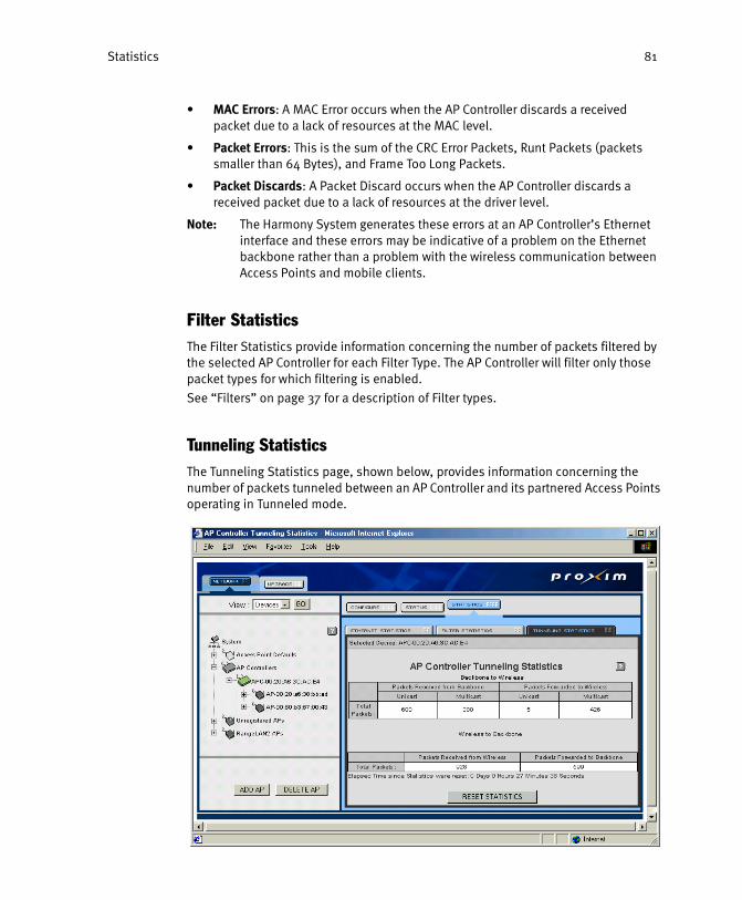
Statistics 81
• MAC Errors: A MAC Error occurs when the AP Controller discards a received packet due to a lack of resources at the MAC level.
• Packet Errors: This is the sum of the CRC Error Packets, Runt Packets (packets smaller than 64 Bytes), and Frame Too Long Packets.
• Packet Discards: A Packet Discard occurs when the AP Controller discards a received packet due to a lack of resources at the driver level.
Note: The Harmony System generates these errors at an AP Controller’s Ethernet interface and these errors may be indicative of a problem on the Ethernet backbone rather than a problem with the wireless communication between Access Points and mobile clients.
Filter Statistics
The Filter Statistics provide information concerning the number of packets filtered by the selected AP Controller for each Filter Type. The AP Controller will filter only those packet types for which filtering is enabled.
See “Filters” on page 37 for a description of Filter types.
Tunneling Statistics
The Tunneling Statistics page, shown below, provides information concerning the number of packets tunneled between an AP Controller and its partnered Access Points operating in Tunneled mode.

Statistics 82
The following statistics appear under the Tunneling Statistics heading:
• Number of Packets Received From the Ethernet Backbone: This statistic is sepa-rated into unicast and multicast packets.
• Number of Packets Received From the Ethernet Backbone That Have Been For-warded to Access Points: This statistic represents the number of tunneled pack-ets that the AP Controller has sent to its partnered Access Points. This statistic is separated into unicast and multicast packets.
• Number of Packets Received From Access Points: This statistic represents the number of tunneled packets that the AP Controller has received from its part-nered Access Points.
• Number of Packets Received From Access Points That Have Been Forwarded to the Ethernet Backbone

Statistics 83
Access Point Statistics
Follow these steps to view the statistics for one of the Access Points:
1. On the left-hand side of the browser screen, click the plus sign to the left of the AP Controllers heading.
2. Click the plus sign to the left of an AP Controller to view the list of its partnered Access Points.
3. Click the icon that corresponds to the Access Point whose statistics you want to review.
4. Click the Statistics tab to view the Access Point’s statistics, as shown in the following example.
An Access Point’s Statistics are divided into three sections: Ethernet Statistics, Bridge Statistics, and Radio Statistics.
Note that the amount of time that has elapsed since the Statistics were last reset is shown on the bottom of each screen. You can clear the existing statistics and reset the time counter to zero by clicking the RESET STATISTICS button.

Statistics 84
Ethernet Statistics
The Ethernet Statistics provide information concerning the number of packets sent and received by an Access Point over the Ethernet network.
The following statistics appear under the Ethernet Statistics heading:
• Packets Received
• Packets Transmitted
• CRC Errors: A CRC Error occurs when a received packet fails the CRC (Cyclic Redundancy Check).
• Frame Alignment Errors: An Alignment Error occurs when a received packet does not end on a byte boundary. This also causes a CRC Error packet.
• Number of Collisions
• Number of Times the Receive Buffer Is Overflown: An Access Point temporarily stores the packets it receives from the Ethernet before forwarding them to the radio network. The Access Point stores these packets in its buffer memory, which only has a limited amount of space available. The receive buffer overflows when the buffer memory is full and the Access Point receives additional packets from the Ethernet network. This may result in lost data or delayed transmissions.
Bridge Statistics
The Bridge Statistics provide information concerning the number of packets exchanged between an Access Point and an AP Controller when an Access Point is operating in Tunneled mode.
The following statistics appear under the Bridge Statistics heading:
• Packets Forwarded to AP Controller
• Packets Forwarded to Radio
• Packets Fragmented: The IP Tunneling protocol used by Access Points and AP Controllers to communicate adds additional overhead to a packet. If the addi-tional overhead added by the IP Tunneling protocol will cause the packet to exceed 1518 Bytes (the largest packet size allowed on an Ethernet network), then the Access Point will break up the packet into several smaller pieces before trans-mitting it to the AP Controller. The AP Controller reassembles the original packet once it has received all of the fragments from the Access Point.
• Packets Reassembled: If the additional overhead added by the IP Tunneling pro-tocol will cause the packet to exceed 1518 Bytes (the largest packet size allowed on an Ethernet network), then the AP Controller will break up the packet into sev-eral smaller pieces before transmitting it to the Access Point. The Access Point reassembles the original packet once it has received all of the fragments from the AP Controller.
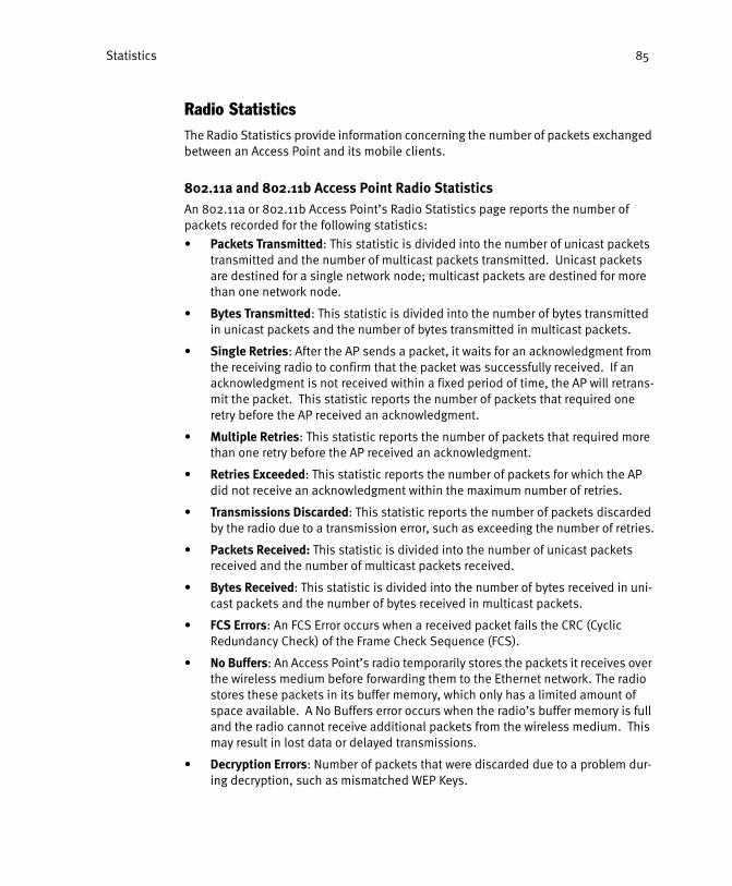
Statistics 85
Radio Statistics
The Radio Statistics provide information concerning the number of packets exchanged between an Access Point and its mobile clients.
802.11a and 802.11b Access Point Radio StatisticsAn 802.11a or 802.11b Access Point’s Radio Statistics page reports the number of packets recorded for the following statistics:
• Packets Transmitted: This statistic is divided into the number of unicast packets transmitted and the number of multicast packets transmitted. Unicast packets are destined for a single network node; multicast packets are destined for more than one network node.
• Bytes Transmitted: This statistic is divided into the number of bytes transmitted in unicast packets and the number of bytes transmitted in multicast packets.
• Single Retries: After the AP sends a packet, it waits for an acknowledgment from the receiving radio to confirm that the packet was successfully received. If an acknowledgment is not received within a fixed period of time, the AP will retrans-mit the packet. This statistic reports the number of packets that required one retry before the AP received an acknowledgment.
• Multiple Retries: This statistic reports the number of packets that required more than one retry before the AP received an acknowledgment.
• Retries Exceeded: This statistic reports the number of packets for which the AP did not receive an acknowledgment within the maximum number of retries.
• Transmissions Discarded: This statistic reports the number of packets discarded by the radio due to a transmission error, such as exceeding the number of retries.
• Packets Received: This statistic is divided into the number of unicast packets received and the number of multicast packets received.
• Bytes Received: This statistic is divided into the number of bytes received in uni-cast packets and the number of bytes received in multicast packets.
• FCS Errors: An FCS Error occurs when a received packet fails the CRC (Cyclic Redundancy Check) of the Frame Check Sequence (FCS).
• No Buffers: An Access Point’s radio temporarily stores the packets it receives over the wireless medium before forwarding them to the Ethernet network. The radio stores these packets in its buffer memory, which only has a limited amount of space available. A No Buffers error occurs when the radio’s buffer memory is full and the radio cannot receive additional packets from the wireless medium. This may result in lost data or delayed transmissions.
• Decryption Errors: Number of packets that were discarded due to a problem dur-ing decryption, such as mismatched WEP Keys.

Statistics 86
OpenAir Access Point Radio StatisticsAn OpenAir Access Point’s Radio Statistics page reports the number of packets recorded for the following statistics:
• Packets Received
• Packets Transmitted
• CTS Errors: Displays the number of Clear To Send (CTS) errors. When an OpenAir AP transmits a packet, it first sends a Request to Send (RTS) message to the packet’s recipient. The packet’s recipient then returns a CTS message to the AP. When the AP receives the CTS, it sends the packet to the recipient. However, if the AP does not receive a CTS within a fixed period of time, the AP will resend the RTS. After a fixed number of retries, the AP will record a CTS Error if a CTS has not been received.
• ACK Errors: Displays the number of Acknowledgment errors. After an Access Point sends a packet, it waits for an acknowledgment (ACK) from the recipient that the packet was successfully received. However, if the AP does not receive an ACK within a fixed period of time, the AP will resend the data. After a fixed num-ber of retries, the AP will record an ACK Error if an ACK has not been received. The number of ACK Errors should generally be very low unless microwave interference is present in the environment.
• Packets Sent BFSK: Displays the number of packets transmitted by the Access Point using the Binary Frequency Shift Keying (BFSK) radio modulation technique. When operating in BFSK, the data rate is 800 Kbps. While slower than QFSK (the AP’s standard modulation technique that provides a data rate of 1.6 Mbps), BFSK provides a more reliable means of communication in harsh radio environments or on the fringe of radio coverage. In addition, the AP will send all multicast mes-sages in BFSK mode to increase the likelihood that these packets will be success-fully received by remote nodes.
• Fragmented Packets Sent: Displays the number of radio packets fragmented by the Access Point to increase the likelihood that data will be successfully received by a Station in harsh radio environments. If the AP has determined that a packet’s recipient is having difficulty receiving a large packet, the AP will split the packet and send it as several smaller packets to be reassembled by the recipient. The number of Fragmented Packets Sent should generally be very low unless microwave interference is present in the environment.
An OpenAir Access Point’s Radio Statistics page reports the following version information:
• Country Code: The range of frequencies available to an OpenAir Access Point var-ies from country to country. Only OpenAir devices with the same country code can communicate.
• Boot Software version: This is also known as the AP’s BootROM version.
• Main Software version: This is also known as the AP’s Flash Code version.
• Radio ROM version

Statistics 87
Station Traffic Statistics
Follow these steps to view the statistics for one of the wireless Stations:
1. On the left-hand side of the browser screen, click the plus sign to the left of the AP Controllers heading.
2. Click the plus sign to the left of an AP Controller to view the list of its partnered Access Points.
3. Click the plus sign to the left of an Access Point to view the list of Stations that are synchronized or associated with the selected AP.
4. Click the icon that corresponds to the Station whose statistics you want to review.
5. Click the Statistics tab to view the Station’s statistics, as shown in the following example.
The Station Traffic Statistics provide information concerning the number of packets the Station has exchanged with its Access Point.
The following statistics appear under the Station Traffic Statistics heading:
• Number of Bytes That the Access Point Has Received From the Station
• Number of Bytes That the Access Point Has Sent to the Station

Statistics 88
• Number of Packets That the Access Point Has Received From the Station: This statistic is divided into the number of unicast packets received and the number of multicast packets received. Unicast packets are destined for a single network node; multicast packets are destined for more than one network node.
• Number of Packets That the Access Point Has Sent to the Station: This statistic displays only the number of unicast packets sent to the Station. Unicast packets are packets that are destined for a single network node.
Note: You can clear the existing statistics by clicking the RESET STATISTICS button.

89
Chapter 8
Access Point Groups
The Harmony System creates groups of Access Points that can be configured and managed collectively.
For example, all of the Access Points installed in the same wing of a building can form a single Group that can be configured and monitored independently of the other Access Points on the network.
Each Access Point is a member of one and only one Group. Each Group contains Access Points of the same radio type. Therefore, an 802.11a Access Point cannot be in the same Group as an 802.11b Access Point.
By default, the Harmony System creates an 802.11a Group, an 802.11b Group, an OpenAir Group, and a Generic Group. In addition to the default Groups, you may also create customized AP Groups.
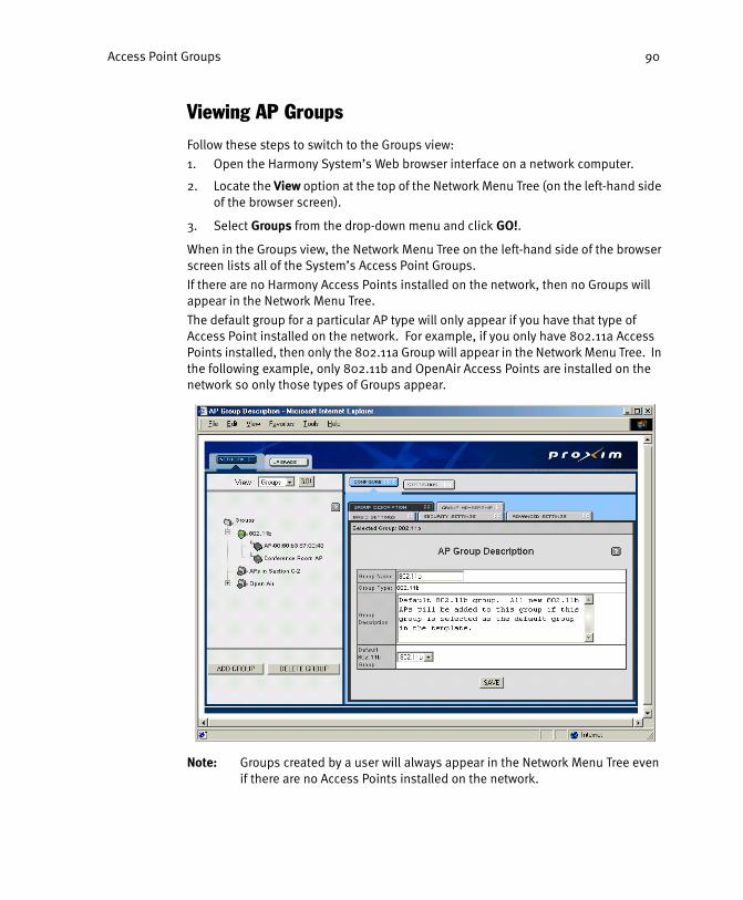
Access Point Groups 90
Viewing AP Groups
Follow these steps to switch to the Groups view:
1. Open the Harmony System’s Web browser interface on a network computer.
2. Locate the View option at the top of the Network Menu Tree (on the left-hand side of the browser screen).
3. Select Groups from the drop-down menu and click GO!.
When in the Groups view, the Network Menu Tree on the left-hand side of the browser screen lists all of the System’s Access Point Groups.
If there are no Harmony Access Points installed on the network, then no Groups will appear in the Network Menu Tree.
The default group for a particular AP type will only appear if you have that type of Access Point installed on the network. For example, if you only have 802.11a Access Points installed, then only the 802.11a Group will appear in the Network Menu Tree. In the following example, only 802.11b and OpenAir Access Points are installed on the network so only those types of Groups appear.
Note: Groups created by a user will always appear in the Network Menu Tree even if there are no Access Points installed on the network.

Access Point Groups 91
Creating a New Group
1. Open the Harmony System’s Web browser interface.
2. Under the View option on the left-hand side of the browser screen, select Groups from the drop-down menu and click GO!.
3. Click ADD GROUP at the bottom of the screen on the left-hand side of the browser window.
4. Enter a Group Name in the field provided, as shown in the following example. The Group Name cannot exceed 21 characters.
5. Select the Group Type from the drop-down list.
6. Enter a Group Description, if applicable. The Group Description can be any text up to 255 characters long.
7. Click ADD GROUP.
8. Click the Network tab in the upper left-hand corner of the browser screen to return to the main Groups screen.
9. Select the new Group on the left-hand side of the browser screen.
10. Configure the Group’s membership and other settings.
11. Click SAVE after making a change to a Group’s configuration page.
Note: Each time you save the Group’s configuration settings, the Access Points in the Group will automatically adopt these new settings (if different from their current configuration).

Access Point Groups 92
Deleting a Group
1. Within the menu tree on the left-hand side of the browser screen, click once to highlight the icon to the left of the Group you want to remove.
2. Click DELETE GROUP to remove the selected Group.
Note: When you delete a Group, the Access Points in that Group will automatically join the Default Group (depending on Group Type).

Access Point Groups 93
Group Configuration
Follow these steps to configure an AP Group:
1. If not already in the Groups view, select Groups from the drop-down menu labeled View: and click GO!.
2. Click the icon that corresponds to the Group that you want to configure.
3. Edit one or more of the Group’s description settings (found under the Group Description tab).
4. Click SAVE to implement these changes.
5. Click the Group Membership tab to add or remove an Access Point from the Group. See “Group Membership” on page 94 for details.
6. Click one of the other tabs to configure the Group’s radio settings. For an 802.11a or 802.11b AP Group, there are three radio configuration screens located under the Basic Settings, Security Settings, and Advanced Settings tab. For an OpenAir or Generic AP Group, there is one radio configuration screen located under the Basic Settings tab.
7. Change the Group’s radio parameters as necessary. For each parameter you change, place a check mark in the box to the left of the parameter name. The Harmony System will only apply the checked parameters to the Group’s members.
Note: Click REVERT to clear any changes you made to the Group’s settings and return to the configured values. However, once the changes are saved, click-ing the REVERT button will not return these settings to their previous values.
8. Click SAVE to apply the selected parameters to the Group’s members.
Group Description
You can configure and view the following settings that describe each Access Point Group on a Harmony System under the Group Description heading:
• Group Name: You can assign a name to the AP Group to identify it within the menu tree. The name cannot exceed 21 characters.
• Group Type: This field displays the type of Access Point supported by the Group, OpenAir, 802.11b or 802.11a. Once a Group has been created, you cannot change the Group Type.
• Group Description: You can provide a description of the Group in the field pro-vided. The description cannot exceed 255 characters.
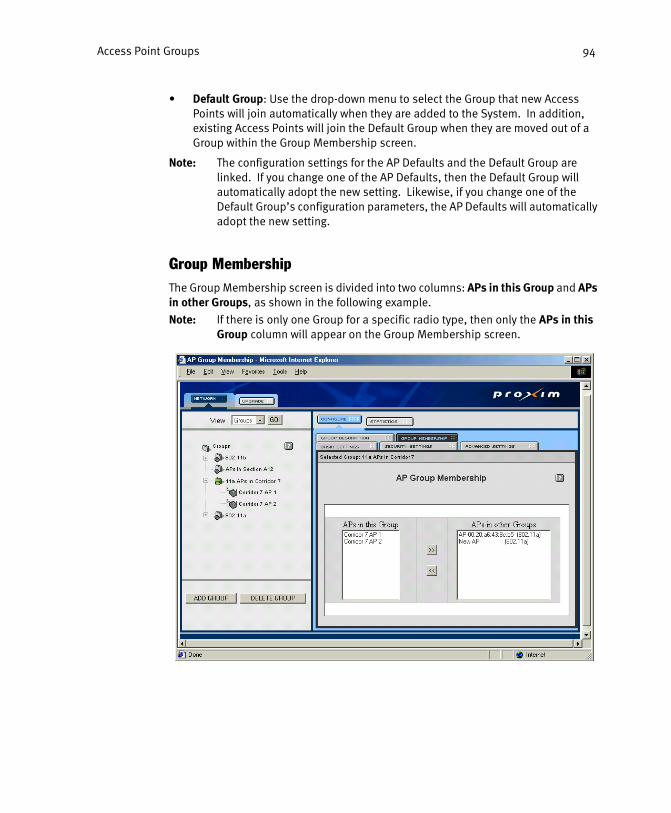
Access Point Groups 94
• Default Group: Use the drop-down menu to select the Group that new Access Points will join automatically when they are added to the System. In addition, existing Access Points will join the Default Group when they are moved out of a Group within the Group Membership screen.
Note: The configuration settings for the AP Defaults and the Default Group are linked. If you change one of the AP Defaults, then the Default Group will automatically adopt the new setting. Likewise, if you change one of the Default Group’s configuration parameters, the AP Defaults will automatically adopt the new setting.
Group Membership
The Group Membership screen is divided into two columns: APs in this Group and APs in other Groups, as shown in the following example.
Note: If there is only one Group for a specific radio type, then only the APs in this Group column will appear on the Group Membership screen.
Access Point Groups 95
The APs in this Group column lists the AP Name for all of the Access Points that are currently members of the selected Group.
The APs in other Groups column lists all of the Access Points that are members of another AP Group. The Access Point’s Group affiliation appears in parentheses next to its AP Name.
All of the Access Points of a specific radio type are listed in one of these two columns, including any Access Points that are currently Unregistered.
Moving an AP into a Group1. Within the APs in other Groups column, click once to highlight the AP that you
want to add to the selected Group.
2. To select multiple APs, hold down the CTRL key while clicking each AP’s entry in the APs in other Groups column.
3. Click the << button to move the selected Access Points into the APs in this Group column.
Note: The APs that you move into the selected Group will automatically adopt the Group’s settings.
Moving an AP out of a GroupFollow these steps to move one or more APs out of the selected Group:
1. Within the APs in this Group column, click once to highlight the AP that you want to remove from the selected Group.
2. To select multiple APs, hold down the CTRL key while clicking each AP’s entry in the APs in this Group column.
3. Click the >> button to move the selected Access Points into the APs in other Groups column. The selected Access Points will automatically join the Default Group.
Note: The APs that you move out of the selected Group will automatically adopt the Default Group’s configuration settings.

Access Point Groups 96
802.11a Group Parameters
An 802.11a AP Group’s radio parameters are divided into three categories: Basic Settings, Security Settings, and Advanced Settings.
You can configure the following parameters to apply to each member of the selected 802.11a AP Group. See “802.11a Access Point Parameters” on page 54 for more information on these parameter.
Basic Settings• Partnered AP Controller
• Auto Image Synchronization
• Operating Mode
• 2x Mode
• SSID
• Subnet Mask
• Default Gateway
Security Settings• Security Level
• WEP Key Size
• WEP Keys
Advanced Settings• Supported Rates
• RTS/CTS
• Fragmentation
• Repeating

Access Point Groups 97
802.11b Group Parameters
An 802.11b AP Group’s radio parameters are divided into three categories: Basic Settings, Security Settings, and Advanced Settings. You can configure the following parameters to apply to each member of the selected 802.11b AP Group. See “802.11b Access Point Parameters” on page 61 for more information on these parameters.
Basic Settings• Partnered AP Controller
• Supported Clients
• Auto Image Synchronization
• Operating Mode
• SSID
• Subnet Mask
• Default Gateway
Security Settings• WEP Encryption
• WEP Key Size
• WEP Keys
Advanced Settings• Supported Rates
• RTS/CTS

Access Point Groups 98
OpenAir Group Parameters
The Basic Settings tab lets you configure the operating parameters for all of the OpenAir Access Points that are members of the specified Group. You can configure the following parameters to apply to each member of the selected OpenAir AP Group. See “Open Air Access Point Parameters” on page 65 for more information on these settings.
Basic Settings• Partnered AP Controller
• Domain
• Security ID
• MAC Optimize
• Auto Image Synchronization
• Operating Mode
• Subnet Mask
• Default Gateway
Generic AP Group Parameters
The Basic Settings tab lets you configure the operating parameters for all of the Generic Access Points that are members of the specified Group. You can configure the following parameters to apply to each member of the selected Generic AP Group. See “Generic AP AutoConfigure Defaults” on page 72 for more information on these settings.
Basic Settings• Partnered AP Controller
• Auto Image Synchronization
• Operating Mode
• Subnet Mask
• Default Gateway

Access Point Groups 99
Group Statistics
Follow these steps to view the operating statistics for an Access Point Group:
1. On the left-hand side of the browser screen, click the icon that corresponds to the Group whose statistics you want to review.
2. Click the Statistics tab to view the Group’s statistics. The Group’s Statistics pages display the statistics for each Access Point that is a member of the selected Group.
Note: Any Unregistered APs that are members of the Group will not appear within the AP Group Statistics pages.
A Group’s Statistics are divided into three sections: Ethernet Statistics, Bridge Statistics, and Radio Statistics. The Ethernet Statistics page for an OpenAir Group is shown in the following example.
Ethernet Statistics
The Ethernet Statistics screen displays the statistics for each Group member on a single page. See “Ethernet Statistics” on page 84 for more information.
Bridge Statistics
The Bridge Statistics screen displays the statistics for each Group member on a single page. See “Bridge Statistics” on page 84 for more information.

Access Point Groups
Radio Statistics
The Radio Statistics screen displays the statistics for each Group member on a single page. For 802.11a and 802.11b Access Points, see “802.11a and 802.11b Access Point Radio Statistics” on page 85 for more information. For OpenAir Access Points, see “OpenAir Access Point Radio Statistics” on page 86 for more information.
Resetting Group Statistics
Follow these steps to reset the statistics for one or more of the Access Points in an AP Group:
1. For each Access Point whose statistics you want to reset, place a check mark in the box labeled Reset Statistics.
2. Click RESET SELECTED AP’S STATISTICS.
Alternatively, click RESET ALL AP’S STATISTICS to reset the statistics for all APs within the Group.

101
Chapter 9
Troubleshooting
The Harmony wireless infrastructure family is designed to be very easy to install and operate. However, if you experience difficulties, use the information in this chapter to help diagnose and solve problems. If you cannot resolve a problem, contact Proxim Technical Support, as described in “Technical Support and Training” on page 116.
Upgrading Harmony Devices
Proxim will periodically post firmware updates for the AP Controller and Access Points to the Proxim Technical Support web site at http://www.proxim.com/support/. There are two types of upgrade files: one for AP Controllers and one for Access Points.
The Web browser interface includes an Upgrade utility to load new firmware images to the Harmony AP Controllers and Access Points on your network. The Upgrade screen also lists the firmware versions currently installed on the Harmony System’s AP Controllers. If updated firmware exists for any of the Harmony products, use the Upgrade utility to send the new image file to the System’s AP Controllers.
Note: Always review any instructions included with new firmware before attempt-ing to upgrade devices on the Harmony System.
Upgrading the AP Controller
Follow these steps to upgrade the AP Controllers on the network to the latest firmware versions:
1. Obtain a new firmware file from Proxim and copy it to the hard drive on a network computer.
2. Open the Web browser interface on the network computer to which you copied the new firmware file in Step #1.
3. Click the Upgrade tab on the main Web browser screen.

Troubleshooting 102
4. Enter the location of the new firmware file in the field provided, as shown in the following example. If you do not know the path, click Browse... to search for the file on the computer’s hard drive.
5. Click Upgrade with selected file.
Note: The upgrade process may take up to five minutes.
The Harmony System will download the firmware file and review its contents. If the file contains a new firmware image for AP Controllers, the AP Controllers will upgrade themselves automatically.
Note: The AP Controllers must have at least firmware version 1.1 installed to auto-matically receive and process firmware images from other AP Controllers. You must individually upgrade each AP Controller on your network if you are upgrading the AP Controllers from firmware version 1.0 to firmware version 1.1 or 2.0.
If the file contains a new firmware image for the Access Points, the Harmony System will automatically update those Access Points that have the Auto Image Synchronization parameter enabled. Also, the Harmony System will prompt you to select the Access Points to upgrade from a list of Unregistered APs and APs that have Auto Image Synchronization disabled.

Troubleshooting 103
If you select an Unregistered AP to upgrade, the Harmony System will automatically upgrade the Access Point the next time the Access Point is connected to the network and rebooted.
Note: When upgrading a Harmony System from version 1.x to 2.0, upload the image file for the Harmony AP Controllers and confirm that the upgrade was successful before attempting to upload the image file for the Harmony Access Points. Refer to the README documentation included with the firm-ware upgrade file for details.
Upgrading an Access Point
You can also choose to upgrade specific Access Points that may have been unavailable when the rest of the System was upgraded.
Note: You do not need to manually upgrade Access Points if you have the Auto Image Synchronization feature enabled. See “Access Point Parameters” on page 53 for details.
Follow these steps to upgrade a new Access Point using a firmware version that has already been uploaded to the Harmony System:
1. Click the Upgrade tab on the main Web browser screen.
2. Click Upgrade using images on this APC.
3. Click once to highlight the device you want to upgrade. To select multiple devices to upgrade, hold down the CTRL key while clicking the entry for each unit.
Note: Click CLEAR SELECTIONS if you decide not to upgrade the selected devices or if you want to begin the selection process again.
4. Click UPGRADE.
The Harmony System will automatically upgrade the selected devices. If you select an Unregistered AP, the Harmony System will automatically upgrade the Access Point the next time the Access Point is connected to the network and rebooted.
Note to OpenAir Access Point UsersOpenAir Access Points connected to busy network segments may hang during an upgrade. In this case, you must manually recycle power to restore device operation. Upon power reset, the Access Point will automatically begin the upgrade again.
If the Access Point is installed in a location where it is difficult to manually reset the unit, determine if the unit is installed on a busy network segment before attempting an upgrade. A busy network segment is one which has more than 20 broadcast packets per second. To determine if the network is busy, monitor the Access Point’s Ethernet LED. If the LED is almost solid or blinking rapidly, do not upgrade the Access Point while it is attached to the network. Instead, temporarily install it on an isolated network with an AP Controller and upgrade it there.

Troubleshooting 104
Getting Help
If you require assistance to install your LAN, Proxim can put you in contact with a Harmony reseller in your area. The reseller is an expert in the design, installation, and maintenance of LANs and will be able to examine your needs and recommend the most cost-effective solution for your LAN whether you are installing a new LAN or adding on to an existing one. For the location of the Harmony reseller nearest you, contact Proxim at 1-800-229-1630 and ask for the Sales Department.
Web Browser Help Screens
Each management page of the Harmony System’s Web browser interface includes a Help button, labeled with a question mark (“?”).
When viewing one of the Harmony System’s management pages, click the ? button to open a Help screen in a new browser window. The Help screen provides information about the configuration options available on that management page.
For example, click the ? on an AP Controller’s Network Configuration page to see a definition for each of the AP Controller’s configuration parameters. Each Help window also includes a link to Proxim’s Technical Support Web site.

Troubleshooting 105
Common Problems and Solutions
Symptom/Question Possible Solution/Answer
The AP Controller does not automatically detect a new Access Point.
• Confirm that the Harmony System’s Allow new APs to be added automatically parameter is set to True.• Confirm that the Link LED is on. If the LED is not on, check your connection to the local Ethernet network. Also, try another Ethernet cable.• Try repowering the unit. The Access Point will try to contact an AP Controller during boot-up. If you are using the external AC power supply, you should connect the AP to the Ethernet network before turning on the unit.• If you are using a Harmony 802.11b Access Point, confirm that the AP Controller Dependence parameter is set to either Dependent or Flexible.• If none of the above solves the problem, manually add the Access Point as described in Chapter 4.
One of the Access Points on the network is listed as an Unregistered AP.
An Access Point will appear as an Unregistered AP if none of the network’s AP Controllers can communicate with it. Typically, this occurs when an AP is disabled, turned off, or not connected to the network.
There are multiple AP Controllers installed on the same IP subnet but they do not all appear in the same browser interface.
Confirm that all AP Controllers have the same System ID. All AP Controllers must have the same System ID to form a single Harmony System.
I can’t access the AP Controller’s local configuration menu.
Verify that you are using a null modem cable and that the terminal session is configured to use 9600 8N1. See page 29 in Chapter 4 for details.

Troubleshooting 106
I can’t ping or access the Web browser interface of a new AP Controller.
Confirm that the network’s DHCP server has assigned an IP address to the AP Controller. If there is no DHCP server on the network, you must configure a network computer with an IP address in the 169.254.0.0 network to communicate with the AP Controller via the AP Controller’s default IP address. Alternatively, assign the AP Controller a static IP address using the local configuration menu. See Chapter 4 beginning on page 29 for details.
I want to reset the AP Controller to factory defaults.
You can reset an AP Controller to factory defaults from within the local configuration menu (accessed over the serial port). Keep in mind the following:
• Do not attempt to reset an AP Controller to factory defaults while it is connected to the network if you have multiple AP Controllers on the network with the same System ID. All members of a Harmony System share the same configuration. If one of the AP Controllers is reset to factory defaults, it will automatically retrieve the existing System configuration from one of the other AP Controllers.• If you reset an AP Controller to factory defaults, all of the Access Points partnered with it will lose any existing configuration settings.
What is the difference between the Authorization Table, the Wired Server Address Filter, and the User Database?
All three of these features enhance the security of the Harmony System.
• The Authorization Table can allow or deny access to wireless clients based on the adapter’s physical address.• The Wired Server Address Filter prevents wireless clients from using TCP/IP to communicate with any network nodes other than those listed in the Server List.• The User Database is used in conjunction with the Harmony Security Protocol to automate encryption key management.
Symptom/Question Possible Solution/Answer

Troubleshooting 107
The Harmony System will not import physical addresses from a text file into the Authorization Table.
Confirm that the text file is in the appropriate format. The text file must list each physical address as six pairs of two hexadecimal digits separated by colons. Each physical address must appear on its own line (that is, the addresses must be separated by a carriage return). Use a text program such as Notepad to create the text file, which should have a “.txt” extension. The first line of the text file must read “#AUTHORIZATION_TABLE.”
An Access Point installed on a remote subnet is not automatically recognized by the Harmony System.
• Confirm that the remote subnet has an entry in the Harmony System’s Subnet Table.• Confirm that the configured Gateway is the IP address of the local gateway that the AP Controller will use to communicate with the remote subnet.• Determine if the router that separates the two subnets does not forward local broadcast traffic.• If the router does not forward the local broadcast packets sent by the Harmony System, then reconfigure the Subnet Table entry. Enter the remote Access Point’s IP address in the Subnet field and use 255.255.255.255 as the Mask. Enter the IP address of the local gateway in the Gateway field. See “Subnet Table” on page 41.
The Power LED on the AP Controller is red.
Try recycling power to the unit. If the LED remains red, contact Proxim Technical Support.
Symptom/Question Possible Solution/Answer

108
Appendix A
Technical Specifications
Parameters
System Parameters
Parameter Range Default
Browser User Name 0-32 characters blank
Browser Password 0-10 characters blank
Authorization Table Usage Unused, Allow Access, Deny Access
Unused
Wired Server Filter Usage Enabled, Disabled Disabled
Repeating Enabled True, False False
Allow New APs to Be Added Automatically
True, False True
OpenAir ARP Cache Enabled True, False False
User Database User Name 1-20 characters N/A
User Database Last Name 1-20 characters N/A
User Database First Name 1-20 characters N/A
User Database Password 1-32 characters N/A

109
Filters
SNMP Configuration
Parameter Range Default
IP/ARP Filtering/Not Filtering Not Filtering
IPX Filtering/Not Filtering Not Filtering
NetBEUI Filtering/Not Filtering Not Filtering
DECNet Filtering/Not Filtering Not Filtering
AppleTalk Filtering/Not Filtering Not Filtering
Other Packets Filtering/Not Filtering Not Filtering
Multicast Filter Filtering/Not Filtering Not Filtering
Multicast Address o1:00:00:00:00:00 to ff:ff:ff:ff:ff:ff
01:00:00:00:00:00
Multicast Mask o0:00:00:00:00:00 to ff:ff:ff:ff:ff:ff
00:00:00:00:00:00
ARP Filter Filtering/Not Filtering Not Filtering
Network IP Address 0.0.0.0 to 254.254.254.254 0.0.0.0
Network Subnet Mask 0.0.0.0 to 255.255.255.255 0.0.0.0
IPX RIP Broadcasts Filtering/Not Filtering Not Filtering
IPX SAP Broadcasts Filtering/Not Filtering Not Filtering
IPX LSP Broadcasts Filtering/Not Filtering Not Filtering
Broadcast Bandwidth Allocation 0-100% 80%
Parameter Range Default
SNMP Support Enabled, Disabled Enabled
Read-Only Community N/A public
Read-Write Community N/A private
Trap Community N/A trap
Trap Target Address 0.0.0.0 to 254.254.254.254 0.0.0.0 (disabled)
Authentication Traps Enabled, Disabled Enabled

110
AP Controller Parameters
OpenAir Access Point Parameters
Parameter Range Default
System ID 1-15 characters Proxim
AP Controller Name 1-21 characters unit’s physical address
IP Address Use DHCP, Specify IP Use DHCP
Parameter Range Default
AP Name 1-21 characters unit’s physical address
Enable AP Enabled, Disabled Enabled
Auto Image Synchronization Enabled, Disabled Enabled
Operating Mode Automatic, Tunneled Automatic
Partnered AP Controller N/A Any
Domain 0-15 0
Channel 1-15 Assigned by AP Controller
Subchannel 1-15 Assigned by AP Controller
Master Name 1-11 characters MASTER
Security ID 0-20 characters blank
Mac Optimize Auto, Very Light, Light, Normal
Auto
Group Membership N/A Default OpenAir Group
IP Address Use DHCP, Specify IP Use DHCP

111
802.11a Access Point Parameters
Parameter Range Default
AP Name 1-21 characters unit’s physical address
Enable AP Enabled, Disabled Enabled
Auto Image Synchronization Enabled, Disabled Enabled
Operating Mode Automatic, Managed, Tunneled Automatic
Partnered AP Controller N/A Any
Enable 2X Mode(Not available in Europe or Japan)
Enabled, Disabled Disabled
Channel (Models 8569 & 8570)
U.S. & Canada: In 802.11a mode: Channels 36, 40, 44, 48, 52, 56, 60, & 64; in 2X mode: Channels 42, 50, & 58
Europe: Channels 36, 40, 44, 48, 52, 56, 60, & 64
Japan: Channels 34, 38, 42, & 46
Assigned by AP Controller
Channel (Model 8571)
U.S. & Canada: In 802.11a mode: Channels 56, 60, & 64; in 2X mode: Channel 58
Assigned by AP Controller
SSID 1-32 characters proxim
Group Membership N/A Default 802.11a Group
IP Address Use DHCP, Specify IP Use DHCP
Security Level No Security, Use WEP for Authentication and Encryption, Use Harmony Security Protocol
No Security
WEP Key Size 64 Bit, 128 Bit, 152 Bit 64 Bit
WEP Key(s)(select one as Default Key)
10 hexadecimal digits for 64-bit encryption, 26 for 128-bit, 32 for 152-bit
blank
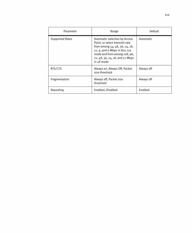
112
Supported Rates Automatic selection by Access Point, or select transmit rate from among 54, 48, 36, 24, 18, 12, 9, and 6 Mbps in 802.11a mode and from among 108, 96, 72, 48, 36, 24, 18, and 12 Mbps in 2X mode
Automatic
RTS/CTS Always on, Always Off, Packet size threshold
Always off
Fragmentation Always off, Packet size threshold
Always off
Repeating Enabled, Disabled Enabled
Parameter Range Default
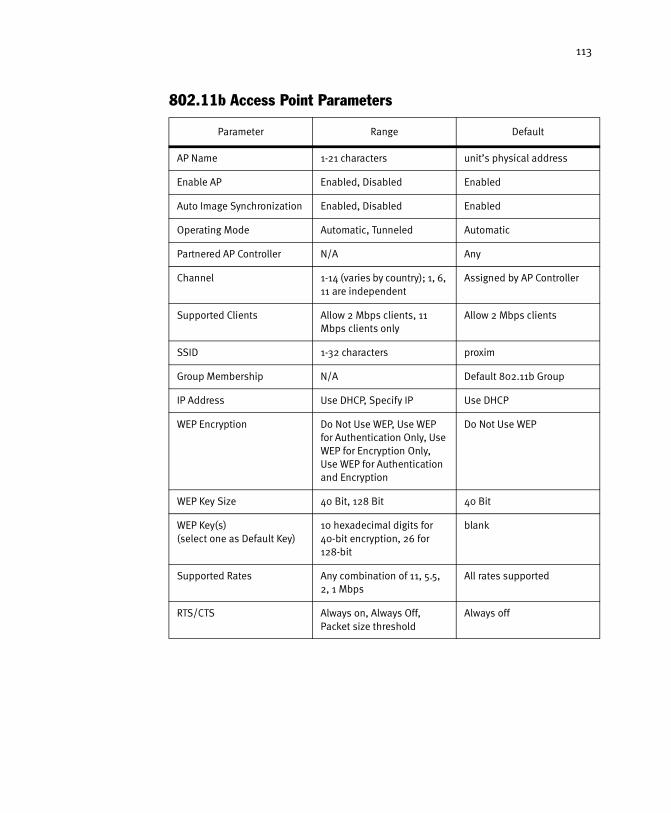
113
802.11b Access Point Parameters
Parameter Range Default
AP Name 1-21 characters unit’s physical address
Enable AP Enabled, Disabled Enabled
Auto Image Synchronization Enabled, Disabled Enabled
Operating Mode Automatic, Tunneled Automatic
Partnered AP Controller N/A Any
Channel 1-14 (varies by country); 1, 6, 11 are independent
Assigned by AP Controller
Supported Clients Allow 2 Mbps clients, 11 Mbps clients only
Allow 2 Mbps clients
SSID 1-32 characters proxim
Group Membership N/A Default 802.11b Group
IP Address Use DHCP, Specify IP Use DHCP
WEP Encryption Do Not Use WEP, Use WEP for Authentication Only, Use WEP for Encryption Only, Use WEP for Authentication and Encryption
Do Not Use WEP
WEP Key Size 40 Bit, 128 Bit 40 Bit
WEP Key(s)(select one as Default Key)
10 hexadecimal digits for 40-bit encryption, 26 for 128-bit
blank
Supported Rates Any combination of 11, 5.5, 2, 1 Mbps
All rates supported
RTS/CTS Always on, Always Off, Packet size threshold
Always off

114
Specifications
The following technical specification is for reference purposes only. Actual product’s performance and compliance with local telecommunications regulations may vary from country to country. Proxim Corporation will only ship products that are type approved in the destination country.
General
Ethernet Architecture .......................Transparent bridge when used in conjunctionwith Harmony Access Points
Redundancy .....................................Automatic fallover to any other Harmony AP Controller
Certifications....................................FCC Part 15 Class B, UL, CE
Compatibility ...................................Provides management, communication andsecurity services for Harmony Access Points(802.11a, 802.11b, and OpenAir)
Warranty ..........................................1-year parts and labor (return to factory)
LED Indicators ..................................Ethernet Link Status and Speed, Power, CPU Utilization
Network Information
Filtering ...........................................Ethernet frame type filtering
Security ...........................................Password protected web-interface;10,000-node access control list;VPN tunnel/IP firewall(s) via Wired Server AccessList; Harmony Security Protocol (802.11a)
Network Interface.............................Autosensing 10/100BaseT (RJ-45)
Network Cabling...............................Standard UTP CAT-5 or STP
Transport Medium ............................Existing switched or routed LAN (Ethernet, Token Ring, ATM, FDDI) or WAN (X.25, Frame Relay, leased line) infrastructure
AP Communication Protocol .............IP- and SNAP-based
APs per AP Controller .......................Varies; dependent on traffic utilization
AP Controllers per System ................30
Roaming...........................................Seamless client roaming among APs includingacross subnets

115
Management
Remote Management .......................HTTP; SNMP
Local Management ...........................RS-232 interface (male DB-9 connector)
Network Address Assignment...........DHCP, auto-IP assignment, or statically assigned
Automatic AP Configuration .............AP Controller configures security, filtering,network and radio parameters, includingautomatic frequency channel assignment
Firmware Upgrade ............................Via HTTP or serial connection
SNMP ...............................................Compliance MIB-II
Statistics..........................................Ethernet, AP radio and link statistics
Environmental
Temperature .....................................0ºC to +50ºC (operational)-20ºC to +65ºC (non-operational)
Relative Humidity.............................85% maximum (operational)95% maximum (non-operational)
Altitude ............................................10,000 feet (operational)40,000 feet (non-operational)
Physical
Dimensions ......................................8.156" (207 mm) L, 11" (279 mm) W, 1.75" (44 mm) H
Weight .............................................1.9 pounds (862 g)
Mounting Option ..............................Rack-mountable
Power Supply ...................................Internal 120/240 VAC, autoranging

116
Appendix B
Technical Support and Training
If you are having a problem using the Harmony Access Point Controller Model 7560 and cannot resolve it with the information in Chapter 9 beginning on page 101, gather the following information and contact Proxim Technical Support:
• What Harmony products are installed on the network?
• What were you doing when the error occurred?
• What error message did you see?
• Can you reproduce the problem?
You can reach Proxim Technical Support by phone, fax, e-mail, or mail:
Tel: 1-800-477-6946 (Toll-free in the U.S. and Canada)1-408-731-2640 (International)
Fax: 1-408-731-3676
Web: http://www.proxim.com/E-mail: [email protected]
Proxim CorporationAttn: Technical Support510 DeGuigne DriveSunnyvale, CA 94085
In addition, Proxim offers technical training courses across the United States throughout the year that are designed to teach customers how to maximize the benefits of Proxim products. These classes are taught by experienced Proxim Systems Engineers and have a technical focus. For class and registration information, visit Proxim’s Web site at http://training.proxim.com.

117
Index
AAccess Point Configuration ..................................................... 31–34, 53Access Point Groups................................................................. 89–100
Membership ..................................................................... 94–95Statistics......................................................................... 99–100
Accessing the Web Browser Interface.................................................. 27ACK Errors ................................................................................... 86Adding a Group.............................................................................. 91Advanced System Parameters ............................................................ 45Alignment Error Packets .................................................................. 80Allow New APs to Be Added Automatically............................................. 45AP AutoConfigure Defaults .......................................................... 69–73AP Controller Dependence ................................................................ 16AP Controller Name ........................................................................ 52AP Controller. See Harmony AP ControllerAP Name ........................................................................... 54, 61, 65AppleTalk Filter ............................................................................. 38ARP Filter..................................................................................... 39Authorization Table............................................................. 43–44, 106Auto Image Synchronization ................................................... 54, 61, 66
BBroadcast Bandwidth Allocation........................................................ 39Browser Password .......................................................................... 37Browser User Name......................................................................... 37Bytes Transmitted.......................................................................... 85
CCarrier Sense Errors........................................................................ 80Channel ...................................................................................... 111
802.11a............................................................................ 55–56802.11b ................................................................................ 62OpenAir ................................................................................ 67
Collisions .................................................................................... 84Computer Name ............................................................................ 76Country Code ............................................................................... 86CRC Error Packets .......................................................................... 80CRC Errors ................................................................................... 84CTS Errors.................................................................................... 86Current AP .................................................................................... 77

118
DDECNet Filter ................................................................................ 38Default IP Address ......................................................................... 29Deferred Packets ........................................................................... 80Delete a Group.............................................................................. 92Devices View ................................................................................. 35DHCP .................................................................................... 28, 52Do Not Use WEP ............................................................................ 63Domain....................................................................................... 66Doze Mode ................................................................................... 45Dynamic Key Renewal Interval........................................................... 58
E802.11a Access Point. See Harmony 802.11a Access Point802.11b Access Point. See Harmony 802.11b Access PointEnable AP.......................................................................... 54, 61, 66ESSID .................................................................................... 56, 62Excessive Collision Packets.............................................................. 80
FFCC .............................................................................................. 2Filters .................................................................................... 37–40Fragmentation .............................................................................. 60Fragmented Packets Sent ................................................................ 86Frame Alignment Errors ................................................................... 84Frame Too Long Packets .................................................................. 80
GGeneric Access Point ................................................................. 72–73
Group Parameters.................................................................... 98Group Description ......................................................................... 93Group Membership ................................................... 56, 63, 68, 94–95Group Name................................................................................. 93Group Type .................................................................................. 93
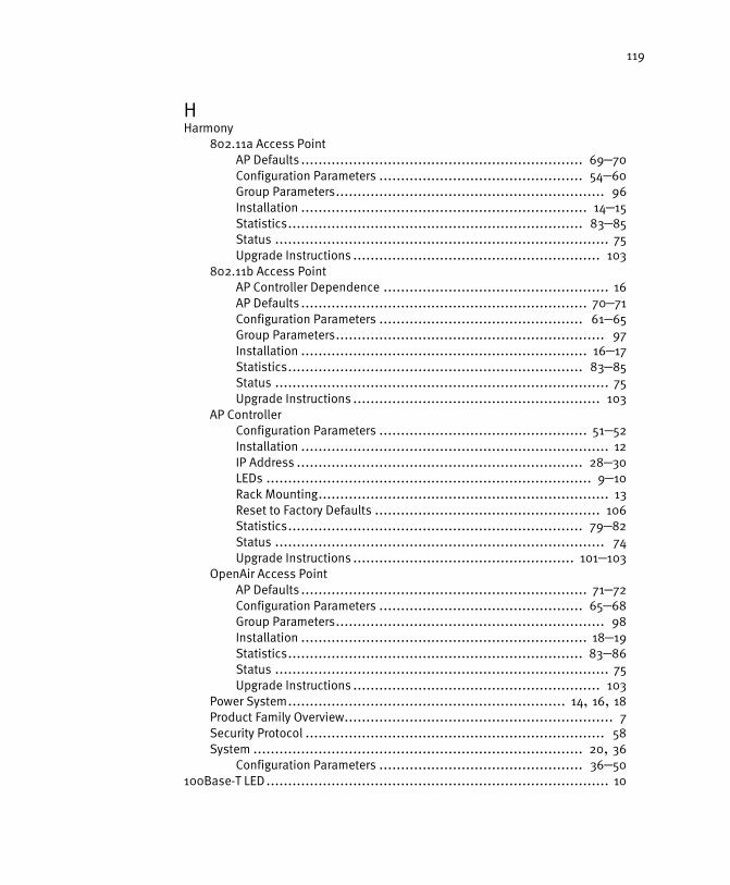
119
HHarmony
802.11a Access PointAP Defaults ................................................................. 69–70Configuration Parameters ............................................... 54–60Group Parameters.............................................................. 96Installation .................................................................. 14–15Statistics.................................................................... 83–85Status ............................................................................. 75Upgrade Instructions ......................................................... 103
802.11b Access PointAP Controller Dependence .................................................... 16AP Defaults .................................................................. 70–71Configuration Parameters ............................................... 61–65Group Parameters.............................................................. 97Installation .................................................................. 16–17Statistics.................................................................... 83–85Status ............................................................................. 75Upgrade Instructions ......................................................... 103
AP ControllerConfiguration Parameters ................................................ 51–52Installation ....................................................................... 12IP Address .................................................................. 28–30LEDs ........................................................................... 9–10Rack Mounting................................................................... 13Reset to Factory Defaults .................................................... 106Statistics.................................................................... 79–82Status ............................................................................ 74Upgrade Instructions ................................................... 101–103
OpenAir Access PointAP Defaults .................................................................. 71–72Configuration Parameters ............................................... 65–68Group Parameters.............................................................. 98Installation .................................................................. 18–19Statistics.................................................................... 83–86Status ............................................................................. 75Upgrade Instructions ......................................................... 103
Power System................................................................ 14, 16, 18Product Family Overview.............................................................. 7Security Protocol ..................................................................... 58System ............................................................................ 20, 36
Configuration Parameters ............................................... 36–50100Base-T LED ............................................................................... 10
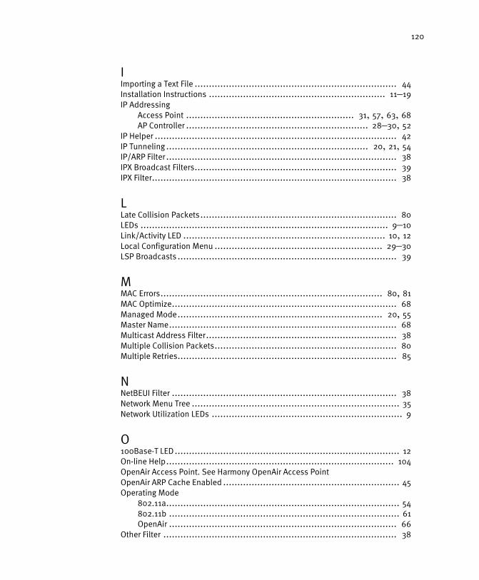
120
IImporting a Text File ....................................................................... 44Installation Instructions .............................................................. 11–19IP Addressing
Access Point ........................................................... 31, 57, 63, 68AP Controller ................................................................ 28–30, 52
IP Helper ..................................................................................... 42IP Tunneling ....................................................................... 20, 21, 54IP/ARP Filter ................................................................................. 38IPX Broadcast Filters....................................................................... 39IPX Filter...................................................................................... 38
LLate Collision Packets..................................................................... 80LEDs ....................................................................................... 9–10Link/Activity LED ....................................................................... 10, 12Local Configuration Menu ........................................................... 29–30LSP Broadcasts ............................................................................. 39
MMAC Errors.............................................................................. 80, 81MAC Optimize............................................................................... 68Managed Mode........................................................................ 20, 55Master Name................................................................................ 68Multicast Address Filter................................................................... 38Multiple Collision Packets................................................................ 80Multiple Retries............................................................................. 85
NNetBEUI Filter ............................................................................... 38Network Menu Tree ......................................................................... 35Network Utilization LEDs ................................................................... 9
O100Base-T LED ............................................................................... 12On-line Help................................................................................ 104OpenAir Access Point. See Harmony OpenAir Access PointOpenAir ARP Cache Enabled .............................................................. 45Operating Mode
802.11a.................................................................................. 54802.11b ................................................................................. 61OpenAir ................................................................................ 66
Other Filter .................................................................................. 38
121
PPacket Discards ....................................................................... 80, 81Packet Errors ........................................................................... 80, 81Packets Fragmented ....................................................................... 84Packets Reassembled..................................................................... 84Packets Received .......................................................................... 86Packets Sent BFSK ......................................................................... 86Packets Transmitted.................................................................. 85, 86Partnered AP Controller ......................................................... 55, 62, 66Password
Browser ................................................................................. 37Harmony Security Protocol ............................................... 48–50, 58
Physical Address ............................................................ 52, 54, 61, 65Power LED ................................................................................ 9, 12Product Package ............................................................................. 8Protocol Type Filters .................................................................. 37–38
RRack Mounting............................................................................... 13RangeLAN2 .................................................................................. 26RangeLAN2 Access Point
Status .................................................................................. 78Receive Buffer .............................................................................. 84Regulatory Information and Warnings ................................................... 2Repeating.................................................................................... 60Repeating Enabled.......................................................................... 45Requirements ................................................................................. 8Retries Exceeded........................................................................... 85RIP Broadcasts ............................................................................. 39Roaming ................................................................................ 24–25
Across Subnets....................................................................... 25RTS/CTS................................................................................. 59, 65
SSAP Broadcasts ............................................................................ 39Security
Wired Server Address Filter ........................................................ 46Security ID ................................................................................... 68Single Collision Packets .................................................................. 80Single Retries ............................................................................... 85SNMP .................................................................................... 47–48Specifications ............................................................................. 114

122
SSID802.11a................................................................................. 56802.11b ................................................................................ 62
Static IP Address ...................................................................... 29–30Station Name ............................................................................... 76Station Status ......................................................................... 76–77Station Traffic Statistics ............................................................. 87–88Subchannel ................................................................................. 67Subnet Table........................................................................... 41–42Supported Clients.......................................................................... 62Supported Rates
802.11a................................................................................. 59802.11b ................................................................................ 64
System Access............................................................................... 37System ID......................................................................... 36, 51, 105System. See Harmony System.
TTechnical Support......................................................................... 116Technical Training......................................................................... 116Topologies.............................................................................. 20–26Transmissions Discarded................................................................. 85Troubleshooting Suggestions .................................................... 105–107Tunneled Mode............................................... 20, 21, 25, 42, 54, 81, 84Tunneling Statistics .................................................................. 81–822X Mode ...................................................................................... 55
UUnregistered AP ...................................................................... 53, 105Upgrade Instructions ............................................................... 101–103Use Harmony Security Protocol ......................................................... 58Use WEP for Authentication Only ....................................................... 63Use WEP for Encryption and Authentication ........................................... 57User Database ........................................................................ 58, 106User Database Configuration ....................................................... 48–50User Name
Browser ................................................................................. 37Harmony Security Protocol ............................................... 48–50, 58
VView AP Groups............................................................................. 90

123
WWarranty Information........................................................................ 2WEP (Wired Equivalent Privacy) .......................................................... 57WEP Encryption............................................................................. 63WEP Key
802.11a.................................................................................. 57802.11b ................................................................................ 64
WEP Key Size................................................................................ 64Wired Equivalent Privacy (WEP) ......................................................... 63Wired Server Address Filter ........................................................ 46, 106