8th year of service to management and engineering
TRANSCRIPT

Price 25 Cents
FM NETWORKER
100
8th Year of Service to Management and Engineering

The mew
e ...Wenn/iye eiota.mai.
LOOK TO RAYTHEON
FOR ALL YOUR NEEDS
Transmitters,Speech
InputEquip -
!rent Antenna,Antenno
Network,
Tower. Frequencyand Modulation
oltage Stabilizers,Tran
Monitors,V
scriptionPloye.s
and Pickups,Re-
corders,Microphones,
Speakers,
Relays,Coaxial
Coble,Replete -
Cent lobes.AM FM IV
RIV1 11E0IAA
V% aNTENTops everything for
HIGHEST GAIN. 2.15 for 10' 6", single section* com-pared with nearest competitive gain of 1.5 for 13' 6"section.
LOWEST COST. Less than anything approaching itsperformance and features.
EASY TO INSTALL. Shipped pre -tuned to your fre-quency - no field adjustments - only one, simple,co -ax feed connection.
PERFECT RADIATION. New "waveguide" radiationprinciple for perfect circular radiation - horizontalpolarization.
NO ICING PROBLEM. Feed elements completelyenclosed by weather-proof radome - no de-icingequipment needed.
FULL POWER. A single section will handle 10KW -available in single, double and four -section assemblies.
NO OBSOLESCENCE. Add new sections for increasedgain.
LOW WIND LOADING. Simple, open, self-sup-porting structure - no protruding elements - offerslowest wind resistance.
PLUS MANY OTHER IMPORTANT FEATURESThe new Raytheon Type RFW Antenna is your idea ...built to answer countless requests for a better, less ex-pensive, trouble -free FM antenna. It's available now!Get the whole story from your Raytheon representativetoday.
'RFW - A (88 - 97 MC.) - single section 11' 6".RFW - B (97 - 108 MC.) - single section 10, 6".
RAYTHEO MANUFACTURI G COMPANWALTHAM 54, MASSACHUSETTS
industrial and Commercial Electronic Equipment, Broadcast Equipment, Tubes and Accessories
BOSTON, MASSACHUSETTSChris F. Brauneck1124 Boylston StreetKE. 6-1364
CHATTANOOGA, TENNESSEEW. B. TaylorSignal Mountain8.2487
CHICAGO 6, ILLINOIS'Warren Cozzens, Ber FarmerCOZZENE 8 FARMER,222 West Adams StreetRan. 745'
DALLAS 8, TEXASHoward 0. Cri,sey41 4 East ' 0th StreetYale 2-1;04
LOS ANGELES 1 5, CaliforniaEmile J. Rome1255 South Flower StreetRich. 7.2358
NEW YORK 17, NEW YORKHenry J. Geist60 East 42nd StreetMu. 2-7440
SEATTLE, WASHINGTONAdrian VanSonten135 Harvard NortL,Minor 3537
WASHINGTON 4, D. C.Raytheon Mfg. Co.739 Munsey BuildingRepublic 5897

ARIACS forSmooth VOLTAGE CONTROL
THE VARIAC* - the original continuously -adjustable auto -transformer - is the ideal device for controlling any a -c oper-ated equipment. VARIACS not only supply perfectly steplesscontrol of voltage from zero, but also supply output voltages17% above line voltage. VARIACS are correctly designed formany years of trouble -free operation. Data below are forsingle-phase operation. Polyphase assemblies are available.
SINGLE-PHASE DATAOUTPUT
E
RATEDAMPS.
MAX.AMPS.
OUTPUTVOLTAGE KVA CASE TYPE PRICE
1 1.5 0-10-1315
5 .170 (1) 200-8 $12.50]
115 5 7.5 0-1 t 50-135
.8621(
(2))(3)
V-5V -5MV-5MT
18.20.5050
25.00
230 2 2.5 0-2300-270 .575
(1)(2)
V -5HV-5HMV-5HMT
21.0023.0027.50
(1) V-10 33.00
115 10 15 0-115 1.725 (2) V -10M 35.500-135 (3) V- 10M T 40.00
(1) V-IOH 34.00230 4 5 0-230 1.15 (2) V-10HM 36.50
0-270 (3) V-10HMT 41.00
*The trade name VARIAC is registered at the U. S. Patent Office.VARIACS are patented under U. S. Patent No. 2,009,013 and aremanufactured and sold only by General Radio Company or its authorizedagents.
115 20 30 0-1150-135 3.45 (4) V -20M 55.00
230 8 10 0-2302.30-270 (4) V-20HM 55.00
( 7) Unmounted model.(2) Protective case around windings.(3) Protective case, terminal cover, line switch, convenience outlet and
6 -foot line cord.(4) Protective case, terminal cover and BX outlet.(5) Two gang assembly - requires type 50-P 1 Choke- $10.00
115 4080
4590
0-1150-135
5
10(4)(5)
50-A50-AG2 (5 )
140.00310.00
230 2040
3162
0-2300-270
714
(4)(5)
50-B50-B62 (5)
140.00310.00
NERAL RADIO COMPANYCambridge 39, Massachusetts
920 S. Michigan Ave., Chicago 5 950 N. Highland Ave., Los Angeles 38

Dealers &Servicemen:Read here why AM -FMprogram duplication means
new, extra PROFITS for you
BROWNING FM TUNER WITH SELF-CONTAINED POWER SUPPLY, TO OPERATE
ANY HIGH-FIDELITY AMPLIFIER AND SPEAKEROR ANY EXISTING AM RECEIVER
Now-Sell Static -Free Reception of All AM Network Programs on the
GENUINE FM BROWNING 11V-10 TUNERSINCE February 1st, all network programs
can be heard with static -free receptionover affiliated FM stations. This applies toNBC, CBS, ABC, and Mutual programs.
This means new, extra profits for dealers,servicemen, and custom set -builders who handlegenuine FM BROWNING Tuners. Here's why:
In all areas where network -affiliated FM sta-tions are operating, your customers can nowget ALL their favorite programs on BROWNINGRV -10 and RV -1 1 FM Tuners-without static,fading, or interference.
When a BROWNING FM Tuner is used with theaudio end of an AM set, it isn't necessary to
use the old set for tuning any more. There'sEXTRA CONVENIENCE.
If a BROWNING FM Tuner is used with a high -
quality amplifier and speaker, the lower priceof the straight FM tuner reduces the cost of theinstallation. There's EXTRA ECONOMY.
In either case, the result is static -free receptionof network programs, with better quality thanon AM. That's EXTRA ENTERTAINMENT.
Order a genuine FM BROWNING Tuner today!Demonstrate its finer reception of AM networkprograms. Use it to get new, extra -profit busi-ness.-Model RV -10, illustrated above. ModelRV -1 1 has 19 -in. panel for rack mounting.
SPECIALISTS IN GENUINE ARMSTRONG FM RECEIVERS SINCE 1940
Browning Labs., Inc.750 Main Street, Winchester, Mass.
In Canada, Address:
MEASUREMENT ENGINEERING, Ltd.Arnprior. Ontario
2
BROWNING LABORATORIES, Inc.750 Main St., Winchester, Mass.Please send me technical details and prices on the following Browningprecision products:
FM Tuners WWV Frequency CalibratorFM -AM Tuners Laboratory OscilloscopeFrequency Meters Capacity Relay
Name
Address
Company Connection
FM AND TELEvisioN

TELEVISIONAND
Edited by Milton B Sleeper * *
FORMERLY, FM MAGAZINE and FM RADIO -ELECTRONICS
VOL. 8 FEBRUARY, 1948 NO. 2
COPYRIGHT 1948, by Milton 8. Sleeper
CONTENTSWHAT'S NEW THIS MONTH
Set Production -A M -F M Duplication-Facsimile 4
FM IS ON ITS WAY TO REPLACE AMEverett L. Dillard 19
UNIVERSAL FM RECEIVERR. S. Hawkins and C. H. Shelton 20
SWEEP GENERATOR FOR VISUAL ALIGNMENTAlbert Welles 24
OPERATING A L.C.C. SYSTEMJohn Sitton 30
AUDIO FACILITIES, Part 1John Green 31
ITEMS FOR SERVICEMENNew Equipment and Test Instruments 34
DISCUSSION OF FM PROPAGATION TESTSMajor Edwin H. Armstrong 36
50 -KW. OUTPUT ON 88 TO 108 MC.Arthur Arigoni 37
MICROWAVE HANDBOOK, Chapter 2Samuel Freedman 40
SPECIAL DEPARTMENTSTelenotes 6Products 8 Literature 8Spot News Notes 26News Pictures 27Advertisers' Index 55
FOE COVER DESIGN AND CONTENTS OF FM ,ND ll I.l.Si DoN M AC CHNE ARE FULLYPROTECTED BY U. S. COPYRIGHTS, AND 511 NOT RI. REPRODUCED IN ANY
MANNER OR IN ANY FORM WITHOUT BRITTEN PERMISSION
* * * * * *MILTON B. SLEEPER, Editor and Publisher
RICHARD H. LEE, Advertising ManagerSTELLA DUCCAN, Production Manager
LILLIAN BENDROSS, Circulation ManagerPublished by: FM COMPANY
Publication Office: 264 Main St., Great Barrington, Mass. Tel. Great Barrington 900Advertising Department: 511 Fifth Avenue, New York 17, Tel. VA 6-2183FM Magazine is issued on the 20th of each month.Single copies 25t - Yearly subscription in the U. S. A. $3.00; foreign $4.00. Sub-scriptions should he sent to FM Company, Great Barrington, Mass., or 511 FifthAvenue, New York 17, N. Y.Contributions will he neither acknowledged nor returned unless accompanied byadequate postage, packing. and directions, nor will FM Magazine be responsible fortheir safe handling in its office or in transit. Payments are made iitinn acceptance offinal manuscripts.
ANDTELEVISION ENZI
C=lifiZO THIS MONTH'S COVERThe finest musical entertain-
ment ever broadcast by radio isnow coming over FM affiliates ofthe Continental Network. Presi-dent and prime mover in thisproject is Everett L. Dillard,whose picture appear,. on thismonth's cover. Key station in thisnet is his WASH -FM W ashing-ton, D. C. It is freely predictedthat Continental will develop intothe 5th national network. Thismay well be the case, for EverettDillard and his associates havesucceeded in meeting problemsthat would have stopped a lessable, experienced, and deter-mined group long ago. There arealready 33 affiliated stations. Mr.Dillard is also president of FMAssociation, comprised of nearly300 stations and manufacturers.
Report No.. 1 from typical13.4R4-FLITX REPROMTCER Users
BROADCASTING ENGINEER REPORTS:
"Acetate Master RecordingPlays 295 Times from a
PARA-FLUX REPRODUCER. . . without material wear"
Protecting precious records today isvitally important. Recordings mustlast as long as possible. The above re-port is a typical result of the minimumwear on records when PARA-FLUXReproducers are used. The new RMClightweight Head permitting the pres-sure of only 20 grams on the record,as well as the low mechanical imped-ance of the stylus, means longer recordlife. All PARA-FLUX REPRODUCERSare tough and durable, yet afford thehighest quality reproduction. UsingPARA-FLUX is your best assurance ofminimum record wear and maximumlife with improved tone quality.
P_IR-1-FLUX REPRODUCERwith interchangeable Heads:
t NIVFIV% . LATERAL ONI.) . . ERTH I 0 N ...
SOLD THROUGH AUTHORIZED JOBBERS
Write for Bulletin PR 1
RADIO -MUSICCOMPORATIONPORT CHESTER NEW YORK
Export: Rock. International Corporation, 13 East 40th Sirimet, New York 16, N. Y.
Entered as second-class matter, August 22. 1945, at the Post Office, Great Barrington, 3fass., under the Act of March 3,1879. Additional entry at the Post Office, Concord, N. H. Printed in the 1% S. A.
MEMBER,AUDITBUREAU OFCIRCULATIONS
3

INDUSTRY'S STANDARD OF QUALITY
DT DICAT ED TO THE CONSTANT BETTERMENT OF SOUND
1.
Important Facts about
ALTEC LANSING
A -323B
AMPLIFIERAmong enthusiasts of FM highfidelity, this Altec LansingA 323B amplifier has achieveda popularity unprecedented inAltec Lansing history.
2. Brings out the final degree ofexcellence of performance of thenew professional -quality tuners,and of the two-way multicellu-lar speaker which has becomethe standard of the broadcast-ing, recording, and motionpicture industries, the AltecLansing Duplex Speaker.Flat frequency response -1 dbfrom 20 cycles to 20,000 cycles.Less than 8% intermodulationat full 15 watts rated output.Engineered to meet all require-ments for a de luxe, custom-built home music system withequalized input for the new,high quality, magnetic phono-graph pickups; radio-phonochangeover switch, and scien-tifically designed low and highfrequency tone controls.
Complete technical informationavailable. Write to Dept. D.
1161 North Vine St., Hollywood 38, Calif.250 West 57th Street, New York 19, N. Y.
3.
4.
5.
HONORED NAME IN AUDIO
ffiONV'Ss 460%;
I. SET PRODUCTION
Z. AM -FM DUPLICATION
3. FACSIMILE STANDARDS
RMA year's end figures on home11 radio set production disclose facts of
great significance to those who are formu-lating 1948 plans.
Most striking is the breakdown of con-sole and phonograph models, for they rep-resent the real profit gravy:
FM consoles 852,256 66%AM consoles 385,926 29%TV consoles 62,256 5%
To take the figures a step farther, hereis the percentage of consoles in the FM,AM, and TV brackets:
FM consoles 73% of FM productionAM consoles 2% of AM productionTV consoles 35% of TV productionThe breakdown of sets made in each
category was:AM setsFM setsTV sets
16,342,002 92%1,175,104 7%
178,571 1%l'ercentagewise, FM and TV receiversmade a small showing, but their higherunit cost indicates that, although amount-ing to only 8% in numbers, they ac-counted for about .50% of the industry'sdollar volume!
-I 17.763 TV TABLE4.465 TV CONSOLE7,117 TV PHONO.
DEC. TOTALTV - 29,345FM- 191,974AM - 1,484599
JF
MA
JJ
M
S
ND
1,509,0001.320.0001,303,0001,639.0001.223,0001,125,0001,074,0001,181.5361,233,70131,827,3661,438,2921/384.599
AM SETS
r7- In 'tN ,T;
1"- O0 q Tb (.4aom,i4Nst N
NN^rr.4'to
4o.
.1i 45 taI 1
JFMAMJJASONDTV SETS
33.081 FM TUNER56225FM TABLE
2,799 FM CONS.97,869 FM PHONO.I
1947 TOTALTV - 176,571FM- 1,175,104AM- 16.342,002
(1YI) r- o'
,:10
8Orrr
JFMAMJJ ASONDFM AM SETS
Manufacturers and dealers can expecta substantial revision in these figures 12months from now. The following infer-ences can be drawn:
. AM set production will drop with abang in 1948, to a total that may not ex-ceed 8 million sets. FM will be at leastdouble last year's figure, probably climb-ing to 21/2 million. TV production may beup 4 times, to something over IA millionsets.
2. There will be fewer set manufac-turers in January, 1949. The going will betough for those who cannot swing overto concentrate FM and TV. The onlyreason most manufacturers will have formaking AM sets in 1948 will be td starttheir lines in the low price -bracket.
3. There will be fewer dealers a yearfrom now.. We would guess that the totalretail radio outlets will drop 20 to 25%.The reasoning behind this estimate is that50% of the dealers will not or cannot han-dle FM and TV receivers, and about halfthat number will find AM sales such slimpickings that they will drop radio com-pletely.
4. Mortality among servicemen will notbe as high, even though a relatively smallnumber will be equipped with either thetest instruments or the knowledge to han-dle FM and TV sets. There will be enoughAM sets to keep them going. Moreover,service organizations geared to FM andTV will tend increasingly to duck AMtable models. They will concentrate onsets priced at levels justifying chargesthat leave a profit above overhead expenseand labor.
With 400 FM broadcast stations onLI the air, the shift from AM to FM hasonly awaited approval of AM -FM pro-gram duplication by the American Fed-eration of Musicians. That approval wasannounced by AFM on January 30, ef-fective February 1.
Lifting of the ban will have far-reachingeffects on broadcasters and set manufac-turers alike, for it marks the beginning ofthe end of AM broadcasting in the UnitedStates. Although no agreement wasreached on live talent for television, theFM -AM settlement will have a bearing ontelevision, too.
It is much too soon to evaluate thechanges. but it is easy to see what willcause them:
1. AFM: The American Federation ofMusicians wants more employment fortheir members in broadcast stations. Work-ing against them has been the progessivecheapening of AM receivers and the re-sultant deterioration of audio quality.Also, sound recording methods have beenimproved to the point where, with increas-ing co -channel interference to cover upthe defects of reception on cheap AMsets, few listeners recognize tile differencebetween live and recorded programs.
(CONTINUED ON PAGE 16)
4 FM AND TELEVISION

Television stations get programs
by telephone lines, too
Thousands of pairs of wire in telephone cablesradiate from every central office. That is whycable pairs will be handy to link cameras andtransmitters wherever a television program mayoriginate.
Since cable pairs are designed first for voicetransmission-top frequency, about 3200 cyclesper second-the loss at picture frequencies upto 4,000,000 cycles is high, so an amplifier is in-serted about every mile. Equalizing networksare also needed to bring the losses at all fre-quencies to the same value.
Recently, the Laboratories have developed a
"video pair" in which polyethylene string andtape are used instead of paper, and which hasa shielding copper tope over all. It is being builtinto new telephone cables which go to pointswhere television programs are certain to orig-inate. Losses are so much less that amplifierscan be four miles apart.
Inside an all-weather sheath, "video" travelssafely and reliably alongside your telephonecall, a sound program, telegraph signals, pic-tures for tomorrow's papers. This service of thetelephone cable was ready when televisionneeded it because of Bell Laboratories activity.
BELL TELEPHONE LABORATORIES PIONEERED !N THE RESEARCH
OF FM RADIO AND TELEVISION. AND ARE ACTIVE IN DEVELOPING IMPROVEMENTS IN BOTH FIELDS TODAY.
February 194S formerly FM, and F.1/ Apio-EI,E("rttoN 5

77. ....... .
ATTENUATIONCURVE
shows total loss plus 10% derotingfactor to allow for resistance of jointsand deterioration with time.Four diameters available: 61/8"-3 1/4"-I1/4" and 74".
Simple New C5:14,4141-* Couplings
ANDREWeieCOAXIAL
TRANSMISSION LINEFOR FM -TV
Offering the dual advantage of easy, solderless assemblyand a constant impedance of 51.5 ohms, this new ANDREWFM -TV line is available in four diameters. Each line fullymeets official RMA standards. It also is recommended forAM installations of 5 Kw or over.
Fabricated in twenty foot lengths with brass connectorflanges silver brazed to the ends, sections are easily boltedtogether. A circular synthetic rubber "0" gasket effec-tively seals the line. Flux corrosion and pressure leaks areavoided. A bullet -shaped device positively connects innerconductors.
Close tolerances are maintained on characteristic im-
pedance in both line and fittings, assuring an essentially"flat" transmission line system.
Mechanically and electrically better than previous types,this new line has steatite insulators of exceptionally lowloss factor. Both inner and outer conductors of all foursizes are of copper having very high conductivity.
Flanged 45 and 90 degree elbow sections, and a completeline of accessories and fittings available.
Better be safe, than sorry. Avoid costly post -installationline changes. Get complete technical data, and engineer.ing advice, from ANDREW now.
CORPOR ATION3 6 3 EAST 75th STREET CHICAGO 19
Pioneer Specialists in the Manufacture of o Complete Line of Antenna Equipment
ElaiYVES
Youngstown, Ohio * Station WFMJ hasplaced an order for television equipment.totalling $250.000. with RCA. This ispart of $400,000 to be spent for televisionfacilities.
Table TV * Included in Philco's new lineof receivers is a table model with a 7 -in.tube, priced at $199.50 plus tax and in-stallation. A somewhat larger table model,with a 10 -in. tube, is $339.50.
WNBT * A new RCA television transmit-ter is being installed at the Empire StateBuilding, New York City. Power will he5 kw. on video and 2.5 kw. on audio. Thechange will he made without interruptingthe service.
Television School * Evening classes in tele-.. i,ion theory and servicing are being con-ducted by the Naylon Television School..223e Pennsylvania Avenue. S.E., Wash-ington. D. C. Director is James J. Greene.
Winnie May * One of the best-known dis-tributors in radio, and the inventor of theradio -cruise plan for entertaining dealers.has taken on the distribution of Andreatelevision receivers for northern NewJersey.
WGN-TV * Tests on the Chicago Tribune'snew station have begun with test -patterntransmission. It is expected that scheduledprograms will start some time in March.
Television Clinic * Advertising executivesare to get facts on television at YankeeNetwork's weekly meetings. under thedirection of general manager Linus Trav-ers. Session will be held in the PrincessBallroom, Hotel Somerset. Boston, Feb-ruary 12, 18, 25, and March 3.
Multiple TV Antenna * A system capable ofhandling 6 to 20 television receivers onone antenna has been announced by Amy,Aceves, and King, Inc., 11 W. 42 Street,New York. It is described as operating onall channels without the use of boosteramplifiers. Multicoupler outlets are avail-able for new buildings with wires run inconduit, or for existing buildings withwires run outside.
TYCP'S * FCC has granted TV construc-tion permits to: Jack Gross BroadcastingCo., San Diego, channel No. 8; StephensBroadcasting Co., WDSI", New Orleans,channel No. 6: and Cincinnati Times -Star, Cincinnati, channel No. 11.
Hollywood * Nassour Studios will erect atheatre and studio for producing televisionfilms at 5746 Sunset Boulevard.
6 FM AND TELEVISION

ea itoligPTRANSCRIPTION
LIBRARY SERVICE
pays offFOR STATION
LOUISVILLE, KY.
/SY
A pay offFOR YOU, TOOI
Lots more listeners in Louisville are dialing WKYW these days ... thanks
to Capitol's Trariscription Library Service. Look at the success of just two of
the shows built with Capitol Transcriptions:
HAL DERWIN SHOW-now in second place among five stations, including
three networks ... and with a Hooper of 3.4! (It's logged in mid -morning,
too, after a program with a much lower rating.)
"WESTERN TRAILS," featuring Capitol's great western and folk talent-
leads all but one big -network show!
Is WKYW happy? They sure are ...CAPITOL Happy!
WKYW has boosted listener levels with Capitol Transcriptions . . . and
so can you! Capitol gives you every imaginable aid: 1. Completely flexible
themes and dated formats for 30 hours of entertainment each week -so
that you can quickly tailor-make a show for any sponsor. 2. Dozens of
Dig -name stars - in every category of musical entertainment. 3. Special
musical themes for your shows. 4. Musical interludes. 5. Artists' voice tracks
for "live" show effect. 6. Unparalleled technical quality.
A matchless combination for lur-ing new listeners and sponsors...and the coupon is your ticketto a free hearing. Use it today!
Sunel and Vine
W 0 0SERVICEPROGRAM
FROM H°
-7
Capitol TronscriplionsSunset & VineHollywood 21. California
Please send me without cost ...I. Demonstration Transcription-to show m what makes Capitol's Service different.2. Complete details about the Library Service and its costs.
iftee demonstrationtranscription
Nome
norCon
Slat en
Sweet and No
Ciry and Stow
L
February 1948 - furincrly Fil, FM 11.Dio-EI:r.:critoxics 7

111101)11CICS&
1,111:11N133111:
So many new instruments, components, andmaterials are being brought out that spacedoes not permit us to publish illustrateddescriptions of them all. Accordingly, ratherthan selecting a few each month, we haveestablished this new department of Products& Literature so that a great number of briefdescriptions can be published. From these,you can select items which interest you, andsend for catalogs or bulletins. We'll appre-ciate it if you will mention FM and TELE-VISION in your requests.
Receiving Tube Manual: New edition of theRCA Manual, for use by designers,servicemen, and instructors, contains 256pages of data on tubes, receiver circuits,amplifiers, and new applications includinglimiters, ratio detectors, discriminators,and multivibrators. Of great value is thenew tube classification chart, giving tubecharacteristics. Separate section is de-voted to miniature tubes. Price 350. -RCA Tube Department, Harrison, N. J.
Condensers: Hermetically -sealed, high -volt-age, low -current power supply for tele-vision receivers and oscilloscopes. Oper-ates on 118 volts, 60 cycles, delivers 2,400volts D.C. Case measures 334 by Sys by5% ins. - Bulletin CPS, Condenser Prod-ucts Co., 1375 N. Branch St., Chicago.
Sepia Encyclopedia: The 6th edition of theMallory Radio Service Encyclopediacovers all prewar and postwar receivers,listing replacements for volume and tonecontrols, condensers, and vibrators, andIF peaks, tube complements, and specialservice notes. Price $2. - P. R. Mallory& Co., Inc., Indianapolis, Ind.
TV Sync Signal Generator: Delivers RMA-FCCstandard horizontal and vertical drivingsignals, composite video blanking signals,and composite sync signals for televisionstudio and film cameras, control units,and monitors, as well as factory produc-tion testing and laboratory work. Rack -mounted units are contained in a steelcabinet 834 by 22 by 184 ins. - BulletinBA, Dumont Laboratories, Inc., 42Harding Ave., Clifton, N. J.
Ceramic -Cased Resistors: Values up to 5,000ohms rated at 7 watts are wire -wound onfibre -glass core, with 2 -in, axial leads.Sealed in steatite tube 134 by 9 6 ins.Smaller 4 -watt size, with resistance up to1,000 ohms, is enclosed in tube 1 by jig in.- Bulletin C7, Clarostat Mfg. Co., Inc.,130 Clinton St., Brooklyn, N. Y.
Microphones: Series of low-priced micro-phones for communications services. Can
be used with desk stand or fitted withhang-up hook. Crystal, dynamic or carbontypes available. Bulletin A37, Electro-Voice. Inc.. Buchanan, Mich.
Time Switch: Compact, wall -mounted timeclock has simple setting for switchinglights or other equipment on and off atany desired time of day or night. Single -or double -pole contacts break 15 amps.Operates on 120 volts, 60 cycles. Lubri-cated for life. - Bulletin S-1050, SangamoElectric Co.. Springfield. Ill.
Constant Voltage Transformers: Designed forlow harmonic distortion. Added circuitcomponent neutralizes harmonics, andlimits distortion to less than 3%. Avail-able in capacities of 250, 500, and 1,000VA. Identical units can be operated inparallel for increased output. - BulletinCVH, Sola Electric Co., 4633 W. 16 St.,Chicago 50.
Radio Data Charts: Time -saving charts forthe design of coils and transformers,speaker dividing networks, transmissionlines, and various components. 93 pages,84 by 11 ins. Price $2. - Iliffe & Sons,Ltd.. Dorset House, Stamford St.. LondonS.E. 1, England.
FM -TV Tuner: Pre -calibrated unit, builtaround the Mallory -Ware Inductuner,provides continuous tuning from 44 to 216mc. covering 13 television channels, FM,and communications. Unit includes com-plete RF head. - Bulletin DL, DuMontLaboratories, Inc., 2 Main St., Passaic.N. J.
TV Test Films: Catalog of test films suitablefor checking 16- and 35 -mm. projectorsand sound reproducers used for televisionbroadcasting. Prepared by the SMPEand Motion Picture Research Council. -Society of Motion Picture Engineers, 342Madison Ave., New York 17.
VatiaCS: New Models of improved mechani-cal design and reduced weight, providecontinuously variable voltage from 115 -or 230 -volt line, with frequencies from25 to 2,400 cycles. - Bulletin NV, Gen-eral Radio Company, Cambridge 39.Mass.
Bridged T Attenuators: Series of small, 20 -step attenuators 2% ins. in diameter,and 2 ins. deep behind panel, or 016 ins.when detent is used. Attenuation charac-teristic is rated essentially flat from 30to 15,000 cycles. Non -inductively wound,and sealed against moisture. - BulletinT20, Shallcross Mfg. Co., Collingdale, Pa.
Ventilated Tower Beacon: Reduced life oflamps in tower beacons, due to collectionof moisture and excessive heat, has beenovercome in a new beacon design. Accord-ing to the manufacturer, a patented domeventilator reduces internal temperature,while moisture is drained through a portin the concave base. Increase in lamp lifeof 15 to 200% is claimed, with corre-
sponding reduction in expense of tower -climbing. - Bulletin PG, Hughey &Phillips, 326 N. LaCienega Blvd., LosAngeles 36.
Red Line Tubes: Specially designed forextremely long life and extra stability.Special girder construction holds elementssecure against shock and vibration. Lifeexpectancy is 10,000 hours. First tubesof this series are: 5691 high -mu triode,5692 medium -mu twin triode, and 5693sharp cutoff pentode. Tubes are identi-fied by red bases. - Bulletin RFM 1000,RCA Tube Dept., Harrison, N. J.
Wire -Recording Heads: Designed for use withall types of auxiliary mechanisms. Record-ing, play -back, and erasing features arecombined in a small unit suited to a va-riety of shielding and mounting arrange-ments. Specified impedances and internalconnections can be furnished to specifica-tion. - Bulletin CH, Shure Brothers, W.Huron St., Chicago 10.
Coded Spaghetti: Extruded thermoplastictubing in continuous rolls, with codedcolor strips which are integral with thematerial. Unlike colored inks appliedexternally, this type of coding cannot fadeor be defaced. - Bulletin ST, Wm. Brand& CompanV, 276 Fourth Ave.. New York10.
S -T Link: Complete equipment for operat-ing in the 940- to 960-inc. band allocatedto S -T service. Comprises transmitter, re-ceiver, monitor, antennas and supports,and transmission line. Can be installedeasily and quickly. - Bulletin GH, RadioEngineering Labs., 35-54 Thirty -SixthSt., Long Island City I, New York.
Engineering Index: A master index of morethan 15,000 articles on radio and elec-tronics published from 1925 to 1945. Titlesare cross indexed under 250 subject head-ings. Cloth bound, 320 pages, 7 by 10ins. Price $17.50. - Electronics ResearchPub. Co.. 2 W. 46 St., N. Y. 19A, N. Y.
Loudspeakers: Designed for FM sets andother applications requiring a high degreeof linearity and low distortion from 100cycles to more than 10,000 cycles. A seam-less parabolic cone is driven by a new mag-net design which concentrates the fluxdensity in the working air gap, with mini-mum leakage. The 8 -in. type is rated at12 to 15 watts. Two 12 -in. types are ratedat 15 to 20 and 25 to 30 watts. Voice -coilimpedances are 4 to 5, 6 to 8, and 6 to 8ohms, respectively. - Bulletin HS -13,Radio Music Corp., Port Chester, N. Y.
Sensitive Relays: Multiple -arm relays forAC or DC operation are available in 3different mounting styles. These are: Octalbase with removable dust cover, octalbase with hermetically sealed cover, andhermetically sealed case with solderingterminals. - Bulletin 50-91, Signal Engi-neering & Mfg. Co., 154 W. 14 St., NewYork 11.
FM AND TELEVISION

Sustained CAPACITY
Mallory Capacitors ActuallyIncrease in Capacity After 2,000* Hours
Install Mallory FP Capacitors with theknowledge that they will last in a "hotset" with temperatures up around185° F.-they will last on the shelf orin an inactive set without needing
reaging-and they will lastwithout loss of capacity.
Mallory is never satisfiedto produce parts that justget by. In all MalloryParts you will find a
generous margin in yourfavor. Mallory capacitorswill operate at 185° F.- that's 35° hotter thanR. M. A. requirements.
THE MAL LO PM!"GOOD SERVICE
FOR GOODBUSI1ESS" PL
will increase husand profits in your slu
1 unique follow-up Iimakes it easy to keep
11/
customers.
ou tie in with Malloryacceptance to developew business-ask vour
BUY MALLORY ASSURED QUALITY
Their RF impedance-their ability towithstand ripple current, are otherplus values that make Mallory
capacitors popular with radio service
men, as well as with manufacturersof radio equipment.
*2,000 HOURS OF OPERATIONAn actual test of Mallory capacitors operatedin an oven at 185°F. and 450 volts DC, plus10 volts of 120 cycle ripple, showed themstill going strong and with increased capacityat the end of 2,000 hours. Typical results:
At Start of TestCapacity Resistance
20.9 mmf 6.16 ohms20.1 mmf 6.5 ohms
After 2,000 HoursCapacity Resistance
23.5 mmf 6.5 ohms23.1 mmf 6.55 ohms
AT REGULAR PRICE LEVELS
P. H. MALLORY a COADC.
ALLORYCATACITCRS . MIIITROLSRATORS .
SWITCHES ... RESISTORS .. . RECTIFIERS ...VIBRAPACIC POWER SUPPLIES ... FILTERS
.Reg. U. S. Pot. OR.
APPROVED PRECISION PRODUCTS
1
P. R. MALLORY & CO., Inc., INDIANAPOLIS 6, INDIANA
February 1948 - formerly FM, and FM RADIO -ELECTRONICS 9

in Sensationally Rapid
Hundreds of Clare Relays are used in this Western Union Push -Button Switchinginstallation. Covers are removed from first four banks at top to show locationof Clare Relays, which play an important part in Western Union's new ultra-modern, high-speed communications program. Pictured is a rear view ofpositions on which the outgoing sides of the various circuits are terminated.
Picture in upper left shows the easily removable Clare mounting base usedin this Western Union installation. The base slips readily into place on jackmountings ... simplifies mounting, assembly, and maintenance.
CLARE RE LAYS"Custom -Built" Multiple Contact Relays for Electrical and Industrial Use
uses CLARE "Custom -Built" Relays
Push -Button Switching System
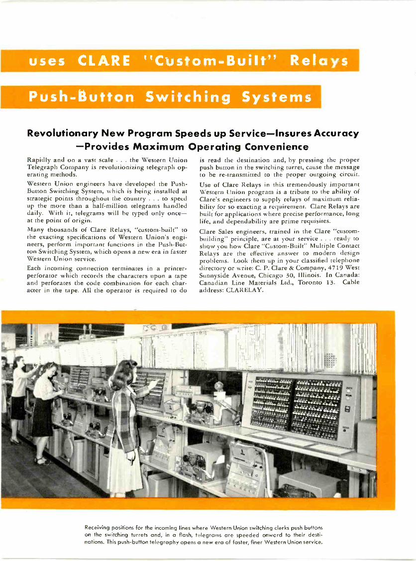
Revolutionary New Program Speeds up Service-Insures AccuracyProvides Maximum Operating Convenience
Rapidly and on a vast scale . . . the Western UnionTelegraph Company is revolutionizing telegraph op-erating methods.Western Union engineers have developed the Push -Button Switching System, which is being installed atstrategic points throughout the country . . . to speedup the more than a half -million telegrams handleddaily. With it, telegrams will be typed only once-at the point of origin.Many thousands of Clare Relays, "custom-built" tothe exacting specifications of Western Union's engi-neers, perform important functions in the Push -But-ton Switching System, which opens a new era in fasterWestern Union service.Each incoming connection terminates in a printer -perforator which records the characters upon a tapeand perforates the code combination for each char-acter in the tape. All the operator is required to do
is read the destination and, by pressing the properpush button in the switching turret, cause the messageto be re -transmitted to the proper outgoing circuit.Use of Clare Relays in this tremendously importantWestern Union program is a tribute to the ability ofClare's engineers to supply relays of maximum relia-bility for so exacting a requirement. Clare Relays arebuilt for applications where precise performance, longlife, and dependability are prime requisites.Clare Sales engineers, trained in the Clare "custom -building" principle, are at your service . . . ready toshow you how Clare "Custom -Built" Multiple ContactRelays are the effective answer to modern designproblems. Look them up in your classified telephonedirectory or write: C. P. Clare & Company, 4719 WestSunnyside Avenue, Chicago 30, Illinois. In Canada:Canadian Line Materials Ltd., Toronto 13. Cableaddress: CLARELAY.
" ' - .4014iii
«.;44e.'
aus dasmArdh4A'rigre rat4:1444:4-4E.
4.. .. . ' 44744414:;4'1
--
Receiving positions for the incoming lines where Western Union switching clerks push buttonson the switching turrets and, in a flash, telegrams are speeded onwc rd to their desti-nations. This push-button telegraphy opens a new era of faster, finer Western Union service.

This seven -tower directional array was designed to protectseveral stations operating on the same frequency. Six towersare used during the night and the seventh, with two nightpattern towers, give excellent daytime coverage. Due tothe location it was necessary to place gravel fills throughthe ice to a depth of over 30 ft. before pile foundationscould be driven to solid ground. Towers are Blaw-KnoxType CN, base insulated 225 ft. high.
BLAW-KNOX DIVISION of Blaw-Knox Company2046 FARMERS BANK BUILDING
PITTSBURGH 22, PA.
BLAW-KNOX DIVISIONOF BLAW-KNOX COMPANY
ANT likikTO/E.
12 ,1/ \ I , I IL I \ I \

for FM
Trade Mnk
COVERAGE and PERFORMANCE
you can't beat Federal's
COMPLETE "ONE -PACKAGE" STATION 13
A broadcast station that's FM by Federal all the way-frommicrophone to antenna-offers three exclusive features thatassure maximum coverage at minimum operating cost, andmaximum performance with minimum maintenance expense.
1. FEDERAL'S SQUARE -LOOP ANTENNA!The coverage of an FM station depends primarily on the effectivestrength of the radiated signal. And Federal's 8 -Element, Square -Loop Antenna gives an effective radiated power more than 8 timesthe transmitter rating. Actual installations have repeatedly provedits ability to give outstanding,coverage-and to withstand highwinds and heavy icing loads.
2. FEDERAL'S HIGH-FIDELITY TRANSMITTER!
All Federal FM transmitters feature the exclusive "Frequematic*"modulator - for outstanding fidelity and performance. Maintainscenter -frequency stability within 0.001% - reduces signal-to-noiseratio to 5600 -to -1 - uses simple all -electronic circuits with standardreceiver tubes - easy to align, simple to maintain.
3. FEDERAL ENGINEERING ALL THE WAY!Complete FM by Federal means FM at its best, with all compo-nents precision engineered to work together. Transmitter console,studio console, transcription units, power supplies - everythingfrom microphone to antenna-designed and coordinated for maxi-mum over-all performance and economy.
When planning your new FM station, remember these exclusiveadvantages. And if youwant to get on the airfast, Federal can nowmake your completeinstallation in recordtime! For further in-formation, write to Fed-eral, Dept. B620.
With this Federal 8 -ElementSquare- Loop Antenna, nowon the air at StationWMRC-FM,Greenville, South Carolina,listeners more than 200 milesaway- including cities in 6different states-report excel-lent reception. Lower photoshows WMRC's transmitterroom, with Federal 10 -Kwtransmitter, console, monitorspeaker and power supply.
Federal Telephone and Radio Corporation
r KEEPING YEARS ..is IT&T's world-wideresearch and engineering organization, of which the FederalTelecommunication Laboratories, Nutley, N. J., is a ur it.
100 KINGSLAND ROAD, CLIFTON, NEW JERSEY
In Canada:-Federal Electric Manufacturing Company, Ltd., Montreal, P.O.Export Distributors:-International Standard Electric Corp. 67 Broad St., N.Y.
FebniarY /94S forni..rly FM, and 1.11 It.k )-14:1.1:("ru()Nics 13

COMPL TETE NT
Here is a complete transmitter maintenance group-providing every measurement necessary for top-flight operationfrom microphone to antenna! Three fast, accurate precisioninstruments in one compact whole - specifically designed foryears of trouble -free performance worthy of the finest FMbroadcast equipment.
These are the -hp- instruments that comprise this group.
1. -hp- 335B Frequency and Modulation Meter.Continuous measurement of carrier frequency andmodulation swing. Low distortion audio output formeasuring and monitoring.
2. -hp- 206A Audio Signal Generator.Provides continuously variable audio frequency vol-tage having a total wave form distortion of lessthan 0.1% from 50 cps to 20 kc.
3. -hp- 330C Noise and Distortion Analyzer.Measures harmonic distortion and noise level fromdemodulated carrier or audio channels. Built -in -vac-uum -tube -voltmeter measures audio level, frequencyresponse and gain.
All instruments have identical panel sizes for convenientmounting in relay racks. Can be delivered in colors and finishesto match your equipment.
GET FULL INFORMATION...WRITE TODAY
HEWLETT-PACKARD COMPANYPAGE MILL ROAD PALO ALTO, CALIFORNIA
This -hp-Maintenance Group Makes These Essential FM BROADCAST MEASUREMENTS
Carrier Frequency: Continuously moni-tored with accuracy well withinF.C.C. limits.
Modulation Swing: Continuously meas-ured at instrument installation andat control console.
Modulation Limit: Alarm lamp flasheson instrument and console whenpre-set level is exceeded.
Aural Monitor: Demodulated signal pro-vides listening check for operator.
Harmonic Distortion: Measured from r -fcarrier or audio channel.
Noise: Measured accurately from FMcarrier or audio channel.
Frequency Response: Overall response,microphone to antenna, of individ-ual units in transmitter set-up.
Audio Transmission: Accurately meas-ures gain of audio channels.
Audio Level: Measured over range from+50db to -60 db at 600 ohm level.
Equalizer Circuits: Characteristics ofcircuits and lines can be checkedaccurately, swiftly.
Oscilloscope Connections: FacilitatesN isual studs of noise and distortion.
14 FM AND TELEVISION
BRIEF SPECIFICATIONS
Frequency Range: Any single frequency,88 to 108 mc.
Deviation Range: +3 kc to --3 kc.
Accuracy: Better than ± 1000 cps.
Modulation Range: Modulation swing100 kc. Scale calibrated 100% at 75 kc.
Audio Output: Supplied with 75 micro-second de -emphasis circuit, flat within1/2 db of standard curve, 20 cps to20 kc.
Monitoring Output: 1 milliwatt into 600ohms, balanced, at 100% modulation.
Size: Panel 101/2"x 19" Depth 13".
BRIEF SPECIFICATIONS
Frequency Range 20 cps to 20 kc, 3bands.
Output: + 15 dbm to matched resistiveloads. 10 volts available for opencircuit.
Output Impedance: 50, 150, 600 ohmscenter -tapped and balanced. 600 ohmssingle -ended.
Frequency Response: Better than 0.2 dbbeyond output meter at all levels.
Distortion: Less than 0.10/0 above 50 cps.less than 0.25% from 20 cps to 50 cps.
Hum Level: At least 70 db below outputsignal, or more than 100 db below 0level, whichever is larger.
Size: Panel 101/2"x 19". Depth 13".
p- 3356
M MonitorAccurate, Stable, Easy to Operas
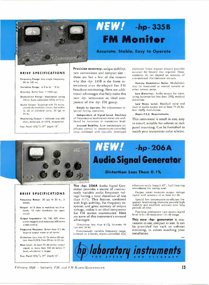
Precision accuracy, unique stability,new convenience and compact size-those are but a few of the reasonswhy this -bp- 335B is the finest in-strument ever developed for FMbroadcast monitoring. Here are addi-tional advantages that help make thisnew -bp- instrument an ideal com-ponent of the -bp- FM group.
Simple to Operate. No adjustments re-quired during operation.
Independent of Signal Level. Readingsof frequency or modulation meter are unaf-fected by variations in transmitter level.
Unusual Stcbility. Low temperature co-efficient crystal in temperature -controlledoven combined with specially developed
electronic linear counter circuits providesaccuracy far beyond that required. Meas-urements do not depend on accuracy ofconventional discriminator circuits.
Remote Modulation Meter. Modulationmay be monitored at control console orother remote point.
Low Distortion. Audio output for meas-uring purposes has less than .25% residualdistortion.
Low Noise Level. Residual noise andhum in audio output are at least 75 db be-low 100% modulation.
Meets F.C.C. Requirements.
This instrument is small in size, easyto install, suitable for cabinet or rackpanel mounting. Can be furnished tomatch your transmitter color scheme.
FRO -hp- 206
Audio Signal GeneratorDistortion Less Than 0.1%
The -hp- 206A Audio Signal Gen-erator provides a source of continu-ously variable audio frequency vol-tage having a total distortion of lessthan 0.1%. This feature, combinedwith high stability, flat frequency re-sponse, and great accuracy of outputvoltage, makes it an ideal componentfor FM station maintenance. Hereare some of this instrument's unusualadvantages:
Distortion less than 0.1% between 50cps and 20 kc.
Continuously variable frequency range,covered in 3 bands, micro -controlled dial,
effective scale length 47", ball -bearingsmoothness for tuning ease.
Output meter monitors output voltagesignal with accuracy of at least 0.2 db.
Special low temperature co -efficient fre-quency determining elements provide highstability and excellent accuracy over longperiods of time.
Precision attenuators vary output signallevel in 0.1 db steps over 1 1 1 db range.
This new -hp- generator is con-venient to use, compact in size. It canbe provided for rack or cabinetmounting, in colors matching yourinstallation.
14.1
Wort! or- q instruments441111r
February 1948 - formerly Fil, and FM RADIO -ELECTRONICS 15

Professional Directory
09anJLy & RaleyAN ORGANIZATION OF
Qualified Radio EngineersDEDICATED TO THE
SERVICE OF BROADCASTING
National Press Bldg., Washington, D. C.
Andrew CorporationConsulting Radio Engineers
363 EAST 75th STREET, CHICAGO 19Triangle 4400
TELEPHONE BRIDGEPORT 5-2055
GARO W. RAYConsulting Radio Engineers
991 Broad Street, Suite 9-11Bridgeport 3, Conn.
LABORATORY: Hilltop DriveStratford, Conn.- Phone 7-2465
Instruments and Measurement,
RATES FOR
PROFESSIONAL CARDSIN THIS DIRECTORY
$10 Per Month for This StandardSpace. Orders Are Accepted
for 1 2 Insertions Only
DALE POLLACKFREQUENCY MODULATION
development and researchtransmitters, receivers
Communications systems
352 Pequot Avenue New London, Conn.New London, 2-4824
THE WOR KSHOPASSOCIATES
INCORPORATED
Specialists inHigh -Frequency Antennas
66 Needham St., Newton Highlands, Mass.Bigelow 3330
WHAT'S NEW THIS MONTH(CONTINUED FROM PAGE 4)
Why, CBS could add the sound of audi-ence applause to recordings of concertmusic and still please the discriminatingdevotees who faithfully tune their radiostogthe Sunday Philharmonic program.
But that's not true of FM. The greatcomplaint against FM broadcasting in thepast has been: "Your live -talent programsare wonderful, but there aren't enough ofthem." FM brings out the best in livetalent, and the worst in recordings. Thus.it is the first development in broadcastingt hat offers a reason for employing musi-cians instead of platters.
BaoAncAsTEas: The AM networkbroadcaster who already owns an FMstation is now sitting pretty. He has ev-erything to gain, and nothing to lose.Some will gain enormously. Witness, forexample, the 250 -watt AM operator witha 50 -kw. FM affiliate. CP holders whoplaced transmitter orders with the manu-facturer who offered the longest delayin delivery are suddenly worried thatthey may have selected second-rate equip-ment. As for the AM holdouts, it is safe topredict that the next few months will seta new record in FM applications filedwith the FCC!
Independent FNI operators are in a dif-ferent position. Their potential audiencewill increase rapidly, because AM-FNIduplication will accelerate the sale of FMreceivers enormously. Whether or notthey gain in number of listeners is a matter of programming. Those who continueto grind out records will find their audi-ences dwindling away. Independent FMstations will not be welcomed as affiliatesof the major AM nets. So they must choosebetween building live programs of special.local interest, or joining an FM network.This puts the Continental Network in avery favorable position, not only becauseit can fill a need but because it providesprogram quality greatly superior to the5,000 -cycle lines used by AM nets. Veryinteresting developments can be expectedin the immediate future, with allout ef-forts by the established nets to head offany threats of new competition.
All this puts the independent AM op-erator who cannot get into FM at the tailof the procession of progress, where hecan only expect to be starved out withinthe next year or two.
3. THANSMITT EP MANUFACTURERS: Thenew look that has come to broadcastingpresents a very favorable picture to manu-facturers of FM transmitters and high -quality sound equipment. Already theestimate of 1.000 FM stations on the airin 1948 is being revised upward. Trans-mitters ordered but still held in ware-houses will move out quickly. Many CPholders who have been asking "how longcan we stall" are demanding "how soon
(CONTINUED ON PAGE 17)
Professional Directory
RAYMOND M. WILMOTTE Inc.
Paul A. deMars
Associate
Consulting engineersRadio & electronics
1469 Church St., N. W. Decatur 1234Washington S. D.C.
RUSSELL P. MAYCONSULTING RADIO ENGINEERS
* * *1422 F Street, N. W. Wash. 4, D.C.
Kellogg Building Republic 3984
LYNNE C. SMEBYConsulting
Radio Engineers820 13th St., N.W. EX 8073
WASHINGTON 5, D. C.
CONSULTING
RADIO ENGINEERS
DIXIE B. MCKEY
ASSOCIATES
1730 CONNECTICUT AVE. N.W.WASHINGTON 9, D.C. ADAMS 3711
NATHANFM AM WILLIAMS
,Consulting Engineer
20 Algoma Blvd.
Phone: Brkhawk 22Oshkosh, Wis.
FREQUENCY MEASURINGSERVICE
Exact Measurements at any lime
RCA COMMUNICATIONS, INC.
64 Broad Street, New York 4, N. Y.
16 FM AND TELEVISION

Professional Directory
FRANK II.
MCINTOSHConsulting Radio Engineers710 14th St. N.W Wash. 5, D. C.
MEtroisilitan 1477
Preliminary sur-veys,managementand operationalconsulting servicebased on practi-cal experiencewith AM, FM andFacsimile.
Phone: EXe,t, o.e 3929
RADIO CONSULTANTS, Inc.1010 VERMONT AVE., WASHINGTON 5, D. C.
ANDERSON &MERRYMAN
Consulting Radio Engineers715 American Bank Bldg. Tel. RAymond 0111
New Orleans 12, LouisianaSuite 1726-28, 33 W. 42nd St. Tel. Wis. 7-9391-2
New York City
Radio Engineering Consultants,
Frequency Monitoring
Commercial Radio Equip. Co.International Building Washington, D. C.603 Porter Building Kansas City, Mo.
SPEECH INPUT EQUIPMENT
U. S. Recording I').1121 Vermont Avenue
Washington 5, D. C.District 16 ill
WINFIELD SCOTT MCCACHRENAND ASSOCIATES
Consulting Radio Engineers
TELEVISION SPECIALISTS
PHILADELPHIA.
809B Windemere Ave.Drexel Hill, Pa.Sunset 2537-W
41C, BOND BUILDING
Washington, D. C.
District 6923
WHAT'S NEW THIS MONTH(CONTINUED FROM PAGE 16)
can we get on the air with FM." This isnot a matter of sudden conversion to anew point of view, but to the urgent needfor preparing to meet whatever competi-tive situation may develop.
As to audio facilities, even many of theFM stations already on the air have feltthat second-rate equipment was goodenough for platter programs. All thattakes on a different aspect as programquality becomes a factor in competitionfor listeners.
The advent of AM -FM duplication doesnot mean the end of transcriptions. butit does mean a shift to high-fidelity tran-scriptions. and replacement of a greatmany of the turntables now in use. Fromnow on, listeners will have live -talentFM as their standard of program quality.
4. RECEIVER MANUFACTURERS: TheRMA has taken the position that FMpromotion which characterizes AM setsas obsolete will hurt the set manufacturerswithout benefiting FM. That was a rea-sonable and logical attitude prior toAM -FM duplication.
Now, that picture has changed. As ofFebruary 1, there is very little reasonfor buying a straight AM model. unlessit's a portable. And new FM portableswill soon eliminate even that reason.
Of course, there may be some areaswhere listeners must still depend on AM,but not for very long. In population cen-ters, where set sales are concentrated, thestraight FM set is virtually an all -pro-gram receiver now!
Here's another factor that must notbe overlooked. Omitting the AM band ef-fects a considerable saving over the costof FM -AM designs. It is easier to attainhigh FM sensitivity when the circuits arenot complicated with AM tuning. Goinga step farther, it is possible to buildstraight FM sets to retail for $50 thatwill run rings around straight AM receiv-ers at the same price.
5. RADIO DEALERS: Two problems con-front radio dealers. First, there is the ques-tion of moving AM sets on hand, makinga wise decision about buying any more,ml getting ready to shift sales efforts
from AM to FM.Such plans must be based on individual,
local conditions. It won't he safe to steercustomers away from FM with such oldanswers as: "I wouldn't advise you toget an FM set. It isn't perfected yet, andthere aren't any decent FM programs."
Each dealer needs to make a carefulstudy of FM stations operating in hisarea, and the CP's already granted. Itwould be well to check with the CP hold-ers to find out how soon they will be onthe air. This will give timetable informa-tion for scheduling further AM set com-mitments.
(CONTINUED ON PAGE 44)
Professional Directory
McNARY & WRATHALLCONSULTING RADIO ENGINEERS
* *
983 National Press Bldg. DI. 1205Washington, D. C.
KEAR C.9 KENNEDYConsulting Radio Engineers
1703 K St. N.W. REpublic 1951
Washington, D. C.
GEORGE P. ADAIRcmixillting Engineers
Radio, Communications, Electronics
1833 M St., N.M.., Washington 6, :.
I-Apr...fire 1230
GEORGE C. DAVIS
501-514 Munsey Bldg. - District 8456
Washington 4, D. C.
WANINS 9-5310
_A. garotte Co.Consulting Enginrs
MECHANICAL-RADIO-ELECTRONICPRODUCT DEVELOPMENT & RESEARCH
Development Specialists in Circuits, Partlists, Models, Manufacturing Drawings.
143-145 W. 22ND STREET, NEW YORK 11
AMY, ACEVES & KING, INC.Specialists in th
Design and Installation of
HIGH -GAINAM, FM, and TELEVISION
ANTENNA SYSTEMSLOngacre 5-6622
11 West 42nd Street, New York 18, N. Y.
.brintry 1948 - formerly FM, and FM RADIO -ELECTRONICS 17
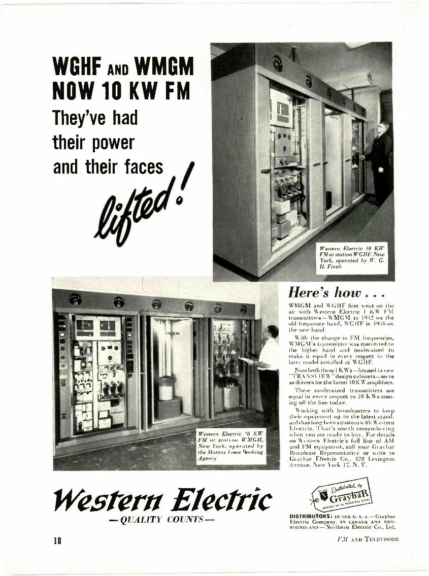
WGHF AND WMGMNOW 10 KW FMThey've had
their power
and their faces
1/
#:
Western Electric !O KWFM at station WMGM,New York, operated bythe Marcus Loew BookingAgency
Western ElectricQUALITY COUNTS -
Western Electric 10 KW 1
FM at station WGHF, NewYork, operated by W. G.H. Finch
Here's how . . .\\ \IGM and WGHF first went on theair with estern Electric 1 KW FMtransmitters -WMGM in 1912 on theold frequency band, \\'GIIF in 1916 onthe new band.
\\ ith the change in FM frequencies,\\ \ 1GM's transmitter was converted tothe higher band and modernized tomake it equal in eery respect to thelater model installed at WGHF.
Now both these 1 KWa-housed in new"TRAN SV1EW" design cabinets-serveas drivers for the latest 10 KW amplifiers.
These modernized transmitters areequal in every respect to 10 K\Vs coin-ing off the line today.
Working with broadcasters to keeptheir equipment up to the latest stand-ards has lonF been a custom with WesternElectric. 1 hat's worth rememberingwhen you are ready to buy. For detailson Western Electric's full line of AMand F\l equipment, call your GraybarBroadcast Representative or write toGray bar Electric Co., 420 LexingtonAvenue, New York 17, N.Y.
DISTRIBUTORS: IN THE U. s. GrayliarElectric Company. IN CANADA AND NEW-FOUNDLAND - Northern Electric Co., Ltd.
18 FM AND TELEVISION
FM IS ON ITS WAY TO REPLACE AM
An Explanation and a Message to the Trade from the President of the Continental Network
EVERY major enterprise must overcomeL a tremendous inertia before it canachieve wide -spread public acceptance.No matter how superior a new servicemay be compared to the older one it re-places, every major invention has en-countered this initial opposition. Thereare always the skeptics who believe thatsecurity lies in maintaining the StatusQuo. Owners of sailing fleets were solidlyopposed to the development of the steam-boat. Carriage -makers said the speedof the automobile was ungodly, andsought to make it illegal. Thomas Edisonwaged a bitter battle against the shiftfrom his DC power systems to the use ofAC. No doubt it was a similar fight whenthe wheel was proposed as a successor tothe drag.
It is perfectly natural for those whohave a firmly intrenched position in anyindustry to oppose a radical improve-ment. If it gains acceptance, large sumsmust be spent to replace the facilitiesrendered obsolete, and invariably theprocess of change opens the door to theentrance of new competitors.
FM has been no exception. For over adecade. Frequency Modulation has beenknown by technicians to be a better sys-tem of broadcasting. Yet because of theearlier obstacles which it had to over-come, and the inertia of industry to adoptits superior transmission and receptionqualities. FM did not become available tothe public on a nation-wide basis until;titer 1945. It goes without saying thatFM would today be the "standard" sys-tem of broadcasting had not a World Warintervened.
VJ-Day inaugurated the second era ofFM- development. Since then, acceptanceof FM by industry and the public alikehas slowly but surely accelerated until,in 1948. we can say "FM is here!"
Post-war FM receiver set productiondid not get under way until late in 1946- too late that year to achieve a sizabletotal. In round figures, 186.000 FM -AMsets were produced. That was but the be-ginning! 1947 was a different story. Morethan 1.175,000 FM -AM sets rolled downthe production lines.
In 1948. if the present rate is main-tained but not increased, manufacturerswill roll up a total of 4.500.000 sets.
But FM -AM set production will not re-main constant. h nill increase. An esti-
General Manager, WASH -FM, InternationalBuilding. Washington, D. C., President, FM Associa-tion, and President, Continental Network.
BY EVERETT L. DILLARD
mated production of FA1 -.01 units be-tween 4,000,000 to 5,000,000 or more isnot an over -optimistic figure for 1948. Indollar volume, the FM receiver set busi-ness will exceed $500 million, while overallinvestment in transmitting equipmentand stations will go over the $100 millionmark.
It is logical to ask the question. "Whythis estimated increase in set productionfor 1948?" To understand the answer, wemust again take a look at the 1947 figures.Last year, 17 million radio sets were man-ufactured. representing a retail value of$800 million. With radio receiver protlue-tion stopped in 1944, and a high obso-lescence factor occasioned because of theintense listening and usage of sets duringthe war years. a tremendous replacementmarket for broadcast receivers of alltypes was built up by 1945. Of the total1947 production, 1,500,000 sets wereautomobile radios. About the same num-ber were manufactured for export. Sev-eral million sets were the so-called "ex-pendable" types. By expendable is meantthe type of receiver which is junked whensomething goes wrong, since the cost ofrepair, in a high percentage of the cases,closely approaches the original cost ofthe receiver. It is easy to see that themore than 1 million FM sets produced in1947 represented a substantial percentageof the dollar volume in domestic homereceivers. One reason for this lies in thefact that 66% of the radio -phonographconsoles were FM -AM models!
Radio manufacturers are enthusiasticabout FM production in 1948. Exceptingthe expendable models and the automo-bile and export radios, the demand forAM -only sets has practically reachedsaturation. Those familiar with industryproblems realize that virtually every setretailing for more than $100 and certainlymost console sets to be manufactured in1948 will incorporate FM. While 1947saw only a few good FM table modelspriced below $100, at least five manufac-turers plan volume production of goodFM -AM table models under $50 in 1948.Furthermore, the FM set market is nownation-wide, with 400 stations alreadyon the air.
There will be a demand for FM sets inevery major city as well as the majorityof the smaller communities. FM is notonly doing a better job in the big cities.but is giving many rural listeners a typeand grade of radio service heretofore un-known to them. FM set production must
be high in 1948 to meet nation-wide de-mand. Sales are not confined to a fewmetropolitan districts. Thus, the manu-facturers and distributors can use theirnation-wide distribution. built up sinceradio began, to sell FM receivers.
Set production and public demand areclosely allied to radio station activity.The more FM stations on the air, thegreater the demand for FM receiversthroughout the country. FCC records in-dicate that 1,000 FM stations will be inoperation by the end of 1948. It was pre-dicted that 700 stations might be on theair by the end of 1947. Slightly less than400 were actually completed. That is theprincipal reason why FM set production(lid not reach the predicted .2 million markin 1947.
But it was not lack of interest that heldhack FM stations. New FM broadcastershad many probletns to overcome. Amongthese were shortages of equipment, tow-ers. antennas. building difficulties, lack ofbuilding materials, and legal delays insecuring zoning permissions. Those de-laying factors are now largely behind us.New FM stations should now be comingon the air at an average rate of about 50per month.
FM activity compared to other types ofbroadcasting can be quickly gauged by in-dustry figures for broadcasting transmit-ters sold in the first 6 months of 1947(latest available information). FM orderstotaled $3.3'25.570, while AM ordersamounted to only $.2,40i,768.
It is only logical that the majority ofAM broadcasters are now anxious to seeFM become an established medium ofsound broadcasting as quickly as possible.The reasons are obvious when it is real-ized that of 1,989 AM broadcasting sta-tions for which const met ion permits havebeen granted. 840 are local 150 -watt sta-tions, with severely restricted night timecoverage due to the added co -channelinterference, and 426 are daytime sta-tions which go off the air at sundown.
All FM stations are licensed for full-time operation. No FM station suffersfrom reduced coverage at night. Only byshifting to FM can broadcasters regainthe nighttime coverage they used to de-liver on AM before the band became socrowded, and justify the continuation oftheir high nighttime rates. Finally, thebroadcasters have come to realize thatwith medium power on FM they can givethe listeners a higher grade of service thanis possible with high power on AM.
February 1948 - formerly FM, and FM RADIO -ELECTRONICS 19

Mm - -was t
O
FIG. 1. THE BUILT-IN SPEAKER PROVIDED IN THIS FM SET CAN BE SWITCHEDOFF IF AN EXTERNAL SPEAKER AND POWER AMPLIFIER ARE USED
A UNIVERSAL FM RECEIVERNational's New Model NC -108 Emphasizes Radio Performance,
with Flexible Audio Facilities
BY R. S. HAWKINS AND C. H. SHELTON
THE National \C-108 FAI receiver wasI designed with a somewhat different
approach to the problem of meeting thewide range of listener requirements as toaudio performance and cost, taking forgranted only the universal demand forhigh sensitivity and noise rejection. Be-yond that point. the receiver affords com-plete flexibility as to the method of in-stallation and the quality of audio re-:punse.
Only in the matter of fine radio per-formance did we undertake to prejudgeindividual preference. There we were onsafe ground. Everyone wants noise -free
*Engineering Departnient, National Company,\Ialden, Mass.
reception of his local stations and as manydistant ones as possible. and without inter -station interference. But we knew thattastes in cabinet styles. wood finishes,loudspeakers. and audio quality and vol-ume are as varied as the homes in whichradio sets are installed.
Accordingly. we concentrated our ef-forts on radio performance and ease ofoperation. added a good audio end and asmall speaker. and put these elements ina very attractive cabinet of convenientlysmall dimensions, as shown in Fig. 1.
Then we went an important step far-ther. We provided a socket into which aseparate power amplifier can he plugged.and output terminals after the detector
FIG. 2. THE SAME CHASSIS IS AVAILABLE WITH A 19 -IN. PANEL FOR RACK MOUNTING
for connecting a separate amplifier, if it isdesired. Thus equipped, the use of theNC -108 is limited only by the imaginationand the resources of the individual owner.
We did make one other contribution toflexibility of application. For those whowanted a specifically professional appear-ance. the same chassis, but with a metertuning indicator, is available on a standard19 -in. panel for rack mounting, Fig. 4.
Custom Installations * with the choice ofcabinet or rack mounting. the installationof this receiver can he as simple or elabo-rate as is required. In either case, the FMreception is only limited by the antenna.That is a factor (and the point cannot beover -emphasized) beyond the control ofany set manufacturer. If a short piece ofwire fastened to the antenna binding postgives satisfactory reception, then that is agood antenna. But the listener who wantsto hear distant stations against a back-ground of absolute silence must have anantenna capable of picking up the signalsand feeding them to the receiver.
The audio amplifier and speaker builtinto this set give excellent quality withinthe limitations of a table model. How-ever. response flat within q. db from 50 to18.00(1 cycles is available at the outputterminals. Thus, with an external am-plifier and speaker. any specifications ofreproduction quality and power can bemet. Even then, the built-in speaker isuseful as a monitor, since it can he cut inor out by the toggle switch at the frontpanel.
Circuit Data * The table model, finishedin gray gloss enamel, has a type 61'5/6Wtuning indicator, while the rack model.with a black, wrinkle -finished panel, isequipped with a tuning meter. This meteris calibrated in db above 5 microvoltsfrom 0 to 80. Actually. the receiver willhandle an input above 80 db withoutoverloading.
As Fig. 3 shows, the ratio type ofdiscriminator is employed. The specialfeatures of this circuit are low backgroundnoise level between stations, good limiter -discriminator action, and good noiseredaction when FM signals are tuned in.
The following circuits and tubes areemployed:
BF amplifier 613A6Mixer 6AG5Hetercxlvne Oscillator . 6C41st IF stage 6SG72nd IF stage 6SG73rd IF stage 6SG7Ratio discriminator 61161st audio 6SJ7Monitor power amplifier . 6V6GT/GTuning indicator 61T5/6G5Rectifier 5Y3GT
The miniature type 6BA6 RF amplifiercontributes appreciably to the overallgain, and provides good sensitivity. The
20 FM AND TELEVISION

sensitivity of this receiver is approxi-mately 7 microvolts for a 30 db signal-to-noise ratio (modulation on -off) with a22.5-kc. deviation. The gain is such thatthis signal will deliver 8 volts of audio tothe high fidelity output terminals withless than 2% distortion, and full poweroutput to the monitor speaker. The RFstage also aids greatly in providing goodimage rejection. The image rejection isroughly 40 db at any frequency in therange of the receiver.
The IF amplifier operates at 10.7 me.Its pass band is 150 ke. at 3 db attenua-tion, and 600 kc. at 60 db attenuation.These characteristics provide ample se-lectivity for reduction of adjacent chan-nel interference, with sufficient passbandto obtain distortion -free reception.
The IF transformers are permeahilitvtuned, and are designed so that coupling.and therefore selectivity, are not alteredby changes in core position encounteredduring alignment. This assures uniformselectivity in production receivers. TheIF transformers are critically coupled and,due to the constancy of coupling. can healigned at center frequency simply h.%
tuning for maximum gain. The constantcoupling is obtained by using a compen-sating winding in series with each primaryand secondary. These windings are ar-ranged so that if more inductance isneeded in the primary for example, thetuning core is moved further into the coil.The core also moves nearer the secondarywinding, so that both primary inductanceand coupling increase. The increase incoupling is automatically off -set by thecompensating winding. Its inductance.remaining fixed, becomes a smaller partof the total primary inductance and.therefore, the coupling due to this wind-ing decreases. These two couplings are soproportioned that the net coupling isunaltered with normal changes in tuningcore positions made during alignment.
A permeability -tuned ratio -type dis-criminator transformer is used. The centertap on the secondary is obtained withcapacitors. so that the tuning slug enter-ing one end of the coil does not unbalancethe two halves of the secondary. It wasfound that even if the secondary weretapped to obtain equal voltages with thetuning core in its normal position, thevariations in production were greatenough that proper alignment could notalways be obtained. The tuning capacitorsare sufficiently accurate so that properalignment is assured. The discriminator isessentially linear over a range of slightlymore than ± 100 kc. The de -emphasis issuch that, taking the transmitter pre -emphasis into account, the receiverfidelity at the output terminals is flatwithin 2 db from 50 cycles to 18,000 cycles.
Receiver gain is high in that a minimumof bias is used on the RF and IF amplifierstages. In fact, the contact potential ofthese tubes and a portion of the ratiodetector load voltage (detector contact
g =-40)-
-II- HHi
f
HHL11-11
440
WI
r
WDn
,,Tt,_
ZoYutifnu
0
HI
IHIV - 9V -8V -7V -IIV -6V -5V -4V -3
FIG. 3. THIS DIAGRAM SHOWS CONNECTIONS FOR A TUNING EYE OR TUNING METER
February 1948 - formerly FM, and FM RADIO -ELECTRONICS 21

potential and rectified noise voltage withno signal) are used to provide a bias ofapproximately .75 volt. The AVC voltageis obtained from the detector and, eventhough it is tapped down, ample AVCaction is obtained.
With the ratio type limiter -discrimi-nator, it is necessary to apply AVC volt-age to the RF and IF tubes, because eventhough dynamic limiting is obtained, theratio detector in itself does not hold theaverage signal level constant. AVCvoltage is not applied to the last IF stage.however, in order to assure that sufficientpower will be obtained to drive the ratiodetector stage properly at all times. Itwas found that with AVC voltage appliedto the last IF stage, the power outputcapability dropped considerably whenappreciable AVC voltage was developed.
The radio -frequency portion of thereceiver presents some rather interestingdesign features. The tuning condenser is ofthe typical grounded -rotor type. AVCvoltage is fed to the grid of the first RFtube through a relatively large resistor,while the RF voltage is fed to the grid bymeans of a condenser in order to preventshort-circuiting the AVC voltage. Thisarrangement avoids the use of large by-pass capacitors in the tuned circuit aswould be necessary if the AVC voltagewere fed through the RF coil to the gridof the RF tube.
Impedance coupling is used betweenthe RF amplifier and mixer stages because
and mixer components are all located ina small area so that both capacitive andinductive coupling is obtained.
Controls are provided for tuning, vol-ume, tone and monitor -speaker switching.The AC power switch is associated withthe tone control. When a separate speaker
tors. The adjustments L3, L5, L7, and1,11. Fig. 3, are accessible from the topof the chassis, and IA, L6, L8, and L10from beneath.
1. Connect the "high" output lead ofan accurately -calibrated signal generatorto the stator of the mixer section of the
FIG. 4. UNDER SIDE VIEW OF CHASSIS SHOWS SIMPLICIT Y OF A STRAIGHT FM RECEIVER
and amplifier are used, the amplifier canbe plugged into the AC receptacle at therear of the receiver chassis. The switchon the receiver then controls the ACpower to both the receiver and amplifier.
FIG.5. NINE TUBES, PLUS TUNING EYE AND RECTIFIER, ARE PROVIDED IN THIS RECEIVER
of the higher gain obtained with thismethod. The 88- to 108-mc. range is rela-tively narrow. As a result, the L/C ratio.and consequently the gain, do not varygreatly over the range.
The plate -tuned oscillator is arrangedso that the rotor of the tuning capacitorcan be grounded. This type of oscillatorhas been found to be very stable. Oscil-lator voltage is injected into the mixermainly by stray coupling. The oscillator
The tone control can be used to providethe normal FM tone range, .or the highscan be attenuated, if desired.
Alignment Data * The alignment procedureshould lie carried out in the followingsteps:
IF AMPLIFIER: The intermediate fre-quency is 10.7 mc. All three IF transform-ers and the ratio detector transformerhave permeability -tuned iron -core indite -
tuning condenser CiC. and the groundlead to any grounded part of the chassis.Set the generator at 10.7 Inc.. and turn offthe modulation.
'2. Connect the DC probe of a high -impedance VTVM to the junction of ItR7and C36 (diode lead) and the commonlead to the chassis. Use the 10 -volt scale ofthe meter.
3. Plug the line cord into an AC socket,110-125 volts, 50-60 cycles.
4. Set the volume control at zero.5. Turn off the monitor speaker switch.6. Set the tone control at zero.7. Adjust the attenuator on the signal
generator for about 3 volts on the VTVM.The diode load voltage is negative withrespect to the chassis.
8. Adjust the IF inductors L3 throughL8 and 1,10 for maximum reading on thevoltmeter, retarding the attenuator tomaintain a reading of about 3 volts. Thisis necessary to assure accurate alignment.
9. Increase the generator output togive a reading of 10 volts on the VTVM.
10. Connect the DC probe of the meterto the junction of Reg and C37. Adjustthe secondary inductor L11 for a readingof 5 volts without changing the attenuatoron the signal generator.
11. Check the voltage with the probeon the junction of R27 and C36. Itshould be twice the reading obtained atR39 and C37. Readjust I,10 and L11 untilthis condition is obtained.
RF AMPLIFIER: The RF amplifier,mixer, and oscillator have trimmer con-densers Cl. C9, and C5 respectively. Foralignment, use a frequency of about 108inc. from a signal generator, crystal oscil-
(CONCLUDED ON PAGE 63)
22 TM AND TELEVISION

SERVICEMEN HAVE A NEW LOOK, TOOIt Doesn't Take a Crystal to See FM, TV, and $$ in Their Future
VES, sir, there's no doubt about it. TheI fair-haired boys of the radio industry
today are the servicemen. Everything isready to make 1948 the FM -TV Year.The broadcasters can supply the pro-grams. Manufacturers can deliver thesets. Dealers can sell them.
But whether or not the sets deliver theperformance that Mr. and Mrs. John Q.Public and the young Publics expect -well, that's up to the servicemen.
The day of handing a radio set to thecustomer and saying, "Here it is, Mister.It's your baby," is all over. Up to now.complaints about reception could be dis-posed of with a sympathetic attitude ex-pressed by, "Yeah, I know, but it's thebest you can expect. All radios sound thesame nowadays."
We're in the FM -TV Year now. Thoseold days are gone forever. The real changein the FM picture came on February I.On that day, things began to happen, andfast. Here is an example:
On February d, we gave a talk on FMand a demonstration of reception it aservice club dinner in a small townnearby. In the afternoon, we put up adipole and checked the set to be sure wecould bring in the AM network programson FM. The demonstration was a greatsuccess. When it was over, the membersasked so many questions it took us anhour to get out of the place.
The next afternoon, a dealer from thattown came in to see us. "Say," he burstout, "you made plenty of trouble for melast night. I was on the phone all morningwith calls from customers who called meeverything from a crook to a jackass."
Finally he took his hair down and ex-plained his situation frankly. He handlesone of the most active lines of receivers ina well-to-do area about 75 miles dueNorth of New York City. In the last year,he sold something over 25 FM -AM phonocombinations at $450 and up. Not onewas installed with an antenna. He said,"I don't think I could have charged themextra for a dipole installation. Probably Icould have given them antennas withoutcharge, but I didn't want to bother withputting them up. So I told them FM pro-grams aren't any good now, but theyshould buy sets with FM because it willbe perfected in another couple of years."
What had brought some of his cus-tomers down on his neck that morningwas that two or three of them had at-tended our FM demonstration the nightbefore. Hearing some of their networkfavorites on FM, without AM nighttime
BY MILTON B. SLEEPER
fading and interference, they recalled the(healer's story that "FM programs aren'tany good now," and they were indignantto the point of being thoroughly mad athaving been misled. We had made thingseven worse for the poor dealer by saying:"If you buy a good FM set, you can havethe same quality of FM reception as youare hearing now. Don't let any dealer tellyou that FM isn't perfected yet. Insist onperformance in your home such as youheard tonight before you pay for the set."
Our visitor had another worry. He saidhis serviceman hadn't tested any of thosesets on FM before they were delivered."Suppose I put up an antenna for one ofthese customers and the FM still doesn'twork? Then what'll I do? My servicemandoesn't know anything about FM, and Iwouldn't dare to have him touch one ofthose jobs!"
We couldn't help him much there ex-cept to say: "You'd better get him asweep generator and an oscilloscope fast,and let him dig himself out of this situa-tion. If you don't, you're liable to findyourself refunding a lot of money, andyou'll be in trouble with your installmentsales."
Well, what was wrong with his picture?You may say that the manufacturer wasto blame. Bringing out a product that iscompletely new from a technical stand-point, the company should have madecertain that the dealer's serviceman wasadequately instructed in handling FMreceivers. That may be so, but most salesdepartments are still not organized on anadequate postwar basis. Manufacturers'salesmen haven't caught up with the fac-tories' technical progress. They have beentoo busy selling sets.
The dealer was at fault, too. As soon ashe had FM sets on his floor, he shouldhave had his serviceman dig into theproblems of FM installation and service.He never should have displayed an FMreceiver before he was prepared to demon-strate perfect FM reception in his store.And he should have made certain thateach set he sold worked perfectly in thecustomer's home. There's enough profit ina $450 sale to cover the cost of putting upa dipole. As sales promotion, one FM re-ceiver working perfectly is worth morethan newspaper advertising that costs tentimes the price of a good installation.
Our dealer's serviceman must take hisshare of the blame, too. Ile carries thetechnical responsibility. The manufac-turer produces a product, the dealer sellsit, the serviceman makes it work and
keeps it in operation. But this servicemanwasn't on his toes. He should have pre-pared himself with information as to whathe would need to install and service FMsets before the first one was delivered.Maybe he was so busy repairing old AMsets that his boss told him to stay in theshop and not waste his time foolingaround with FM. We don't know.
Two things are certain, however. Oneis that the dealer made an awful liar out ofhimself, and his customers found it out.The other is that those very profitablesales of $450 sets are going to stop until hemakes good on the sets he's sold already.
We do know that he'll have to movefast to get a serviceman who can handleFM sets. Maybe the man he has can learnto do it. If not, the dealer will have to finda good man and hire him away from hispresent employer.
That brings us back to what we said inthe beginning: the fair-haired boys of theradio industry today are the servicemen.But we mean the postwar type of service-men - the kind who have the training tohandle technical problems created by FMand television, or those who are suffi-ciently on their toes to acquire the knowl-edge that's needed now.
This may mean taking a correspondencecourse, going to night school, or spendinga few weeks at a set manufacturer's plant.It also calls for the most careful study ofmagazines and technical literature, tokeep up with the rapid progress of newequipment.
The serviceman now has an addedfunction to perform. He is the logical oneto instruct the salesmen in such technicaldetails as they need to know. Not thatsalesmen should attempt to be technicalwhen they talk to customers, but theyneed enough background information sothey won't mislead customers or makepromises beyond the capacity of the sets.Also. the salesmen must be kept posted asto FM and TV stations that can be pickedup, exactly where the stations can befound on the tuning dial, and what newstations are under construction or beingplanned for the immediate future. Also,they need to know the network affiliationof each FM station. This is exceedinglyimportant, particularly now that net-work programs are on FM. The averageprospective customer hasn't the faintestidea what he can expect to hear, and manyhave been told that there aren't any goodFM programs. In addition, the salesmenmust be kept posted on special high -
(CONCLUDED ON PAGE 52)
February 1948 - formerly FM, and FM RADIO -ELECTRONICS 23

GENERATOR FOR VISUAL FM AND TV ALIGNMENTGenerator Covers 2 to 226 Mc., With Sweep Range of .5 to 9 Mc.
IT is axiomatic today, among those quali-fied to speak with authority, that satis-
factory and rapid alignment of wide -bandRF and IF amplifiers must be accom-plished by visual means. In days nowfortunately past, receiver manufacturersprovided instructions for non -visual align-ment. It seems a quite safe assumptionthat such were made only because of theunavailability of satisfactory wide -rangesweep signal generators essential to visualalignment. There is neither profit norsatisfaction in the exasperating, time-consuming. and fatiguing job of IF align-nent of FM sets without benefit of sweepgenerator and 'scope. And even with amultitude of repetitious and tiresome
. checks, there is no certainty that wide -band amplifier alignment, by other thanvisual means, will come within the mini-mum degree of accuracy required.
Generator Characteristics * Practically anystandard type of oscilloscope can be usedfor aligning FM and television receivers.The problem has been to find a suitablesweep signal generator priced within themeans of the average serviceman. Theinstrument illustrated here represents anew and rather unique approach to thesolution of that problem. The model 909Silver generator provides a source of RFvoltage adjustable as to magnitude andas to the extent of center -frequency devia-tion. The sweep rate is 2 X power -linefrequency. The center, or carrier, fre-quency range is adjustable from 2 to 226mc. without band -switching. althoughthere are three frequency ranges cali-brated on the 3 -in. vernier -driven dial.
Output voltage is variable from lessthan 100 microvolts up to not less than..5 volt on all bands. Sweep range is fromapproximately 40 kc. to slightly over 10mc., controllable by a panel knob cali-brated from .5 to 9mc. Saw -tooth voltageat 2 X power -line frequency is providedfor application to the horizontal amplifierof the 'scope.
Sweep Circuit* In any sweep generatordesigned for research, production test, andservice usage, it is desirable if not manda-tory that the order of frequency sweepobtained at any given adjustment of thecontrol shall be substantially the same atall center -frequency settings. This auto-matically rules out the direct frequencymodulation of any variable frequencyoscillator. That is because the very opera -
* McMurdo 'Silver Co., Inc., 1240 Main Street,Hartford 3, Conn.
BY ALBERT WELLES *
tion of applying frequency modulation toan oscillator necessitates variation ofeither the inductance, the capacitance, orboth of its frequency -determining circuit.The C or L variation which can be utilizedto produce frequency modulation is quitesmall, but in any case will be an inescapa-
modulator is quite small, and as it isnecessary to translate such small variationinto a quite large frequency change forTV work, it follows that the reactance-tube -modulated oscillator must be oper-ated at a high frequency, and with verylow circuit -tuning capacitance. This re -
FIG. 1. THE CIRCUIT OF THIS SWEEP GENERATOR PROVIDES 3 FREQUENCY RANGES, COV-ERING 2 TO 226 MC WITHOUT THE USE OF BAND -SWITCHING
ble variable with respect to the circuitelement it is intended to modify if thelatter is tunable over any appreciablerange.
Thus it has become accepted practiceill sweep generator design to use the beat-ing oscillator principle. If two oscillatorsare employed, one may be operated at afixed frequency and modulated by eithermechanical or electrical means. 'lice sec-ond oscillator may be tunable. The sum ordifference frequency. obtained through asuitable mixer, can then be taken to pro-vide carrier frequency modulation. Thissystem requires but a single scale to indi-cate the magnitude of frequency sweep.since the sweep remains constant as car-rier frequency is varied.
Frequency modulation can be appliedto an oscillator by mechanical means, asthrough the agency of a vibrating capaci-tor; or by the seemingly more desirablereactance -tube modulator. The latter ap-pears to have the dual advantages of lend-ing itself more readily to operational con-trol of sweep range, as well as insuringbetter and more easily attained linearityof sweep. Since, however, the effective Cor L variation possible to a reactance
quireritent, coupled with the ever-presentproblem of frequency stability, has taxedingenuity in the past. The advent of anew UHF dual triode of extremely lowand stable inter -electrode capacitance,together with the designer's dream of highGm, high Mu, and low Rp has made itpossible to obtain stable. linear electronicsweep of over 10 mc. in this new instru-ment.
The model 909 sweep signal generator,Fig. 1, employs but three tubes (actually6 independent electron streams), yet itprovides important advantages in greatercarrier frequency range, sweep range, out-put voltage, and frequency stability thanhave been available for FM and TN' visualalignment work in the past. It does thiswith the utmost mechanical and electricalsimplicity, and at a modest price. Cer-tainly the need for such an instrument isindicated by the rapidly increasing sales ofFM and television sets.
Arrangement * The interior view, Fig. 2,does not present the complicated assem-bly of components that might he ex-pected. However, this is a virtue both asto convenience and price. At the lower
24 FM AND TELEVISION

right is the power supply transformer,with a phenolic panel projecting upwardfrom its core mounting. Only the 6X4full -wave rectifier tube is visible on thispanel, the electrolytic filter capacitors andfilter resistor (replacing the conventionalchoke with considerable saving in space)being mounted upon the reverse side.
At the center is the very compact ca-pacitor for the variable -frequency oscilla-tor. A phenolic panel to its left carriesthe 12AT7 tube functioning as a variable -frequency oscillator and mixer. Directlyabove this tube appears the tubular con-centric air -trimmer required to set thedial calibration at the high -frequency end,with the low -frequency core -adjusting endof the ceramic VFO coil form at upperright.
At the extreme left of this panel is the12AT7 fixed-frequencyoscillator/reactance-modulator tube, with the adjustable -corecoil for this circuit immediately above it.Below the fixed -frequency oscillator tubethe molded -carbon output control poten-tiometer is visible, with the co -axial out-put cable passing diagonally beside it atthe left.
Three Bands, No Switch * Of the 3 carrierfrequency ranges, the outer scale is cali-brated in the opposite direction from the2 inner scales. This may be a little difficultto understand, in view of the absence ofband switching. and the obvious sim-plicity of the variable frequency oscillator.The 3 ranges are attained in this manner:The fixed -frequency oscillator, operatingat 114 mc., is varied at the power -linefrequency rate by the reactance modu-lator triode. The single 12AT7 dual triodeaccomplishes both these functions. Thevariable -frequency oscillator covers 112 to37 mc. It is evident that the resultingdifference -frequency range is 2 to 77 mc.This is range No. 1. calibrated upon theinner arc Of the dial. Range No. 2 is thesecond harmonic of range No. 1, presentin amplitude comparable with the fun-damental frequency by virtue of theshort excitation -cycle of both oscillatorsand through mixer -circuit conformation.Range No. 3 is where ingenuity comesinto play. It is well known that two beat-ing oscillators produce simultaneouslyboth sum and difference frequencies in theoutput of a mixer to which they arc fed.
Range No. 3, calibrated upon the outerarc of the dial and in reverse slope to thetwo inner scales, is the sum frequency ofthe two beating oscillators. Thus, the114-mc. FFO added to the range of 37 to112 mc. provided by the VFO yields auseful range of 151 through 226 mc. Thisperfectly obvious system provides 3
ranges with the superior frequency sta-bility possible only to single -range UHFoscillators.
At least 5 frequencies are present simul-taneously in the output of this sweepgenerator. They consist of the fundamen-tal frequencies of the FFO and the VFO,
the difference frequency, its second har-monic, and the sum frequency of the twooscillators. This may at first thought ap-pear undesirable. It is of no momentwhatsoever in practice, for no wide -bandFM or TV amplifier will be so wide, evenif badly misaligned, as to fail to reject thefar -separated, unwanted frequencies inthe output of the sweep generator.
Marker Oscillator * The engineer familiarwith previous sweep generator designs willnote the absence of a marker oscillator orabsorption wavemeter circuit. This is in-tentional, on the apparently sound theory
REACT.MOD.
12AT7-1
Co- 12AT 7-4'
V.F.O.37-112 MC.
105-125V.5o -eon,
POWERTRANS
6X4FULL-1NARECT.
F. E0.114 MC.
IXER
OUTPUT
F I LT ER
120-CY.
117R.SYNC.VOLTSAW -TOOTH
FIG. 2. THIS BLOCK DIAGRAM SHOWS THE4 FUNCTIONS OF THE TWO 12AT7 TUBES
that any user will have at least one signalgenerator or calibrated test oscillatorhandy. By using such instrument asmarker oscillator when one is required,the cost -penalty of having to buy a dupli-cate in the basic sweep generator is elimi-nated.
Calibration * It is evident that, eventhough the two beating oscillators in anysweep generator are of unusual excellence
in themselves, a low difference -frequencyoutput cannot possess the same percent-age of accuracy in dial calibration as thetwo oscillators individually. This is ex-emplified by the condition at 2-mc., pro-duced by beating 114 mc. against 112 me.
In this particular instrument, neithershort- nor long-time stability has provena problem. Over 8 -hour operating periods,the 2-mc. output has never been found todrift more than 3 kc. This speaks volumesfor the stability of the two UHF oscilla-tors. The only remaining problem is thatof dial calibration accuracy. This themanufacturer recognizes in recommendingthat each instrument be checked imme-diately it is put into use. Specifically, thefactory dial calibration should be checkedat most -used frequencies against a known -accurate test oscillator, and correct dialreadings for IF and RF points spotted onthe dial.
Saw -Tooth Voltage * No review of this newgenerator would be complete without ref-erence to the method of obtaining 120 -cycle saw -tooth horizontal synchronizingvoltage to produce a super -imposedmirror -image trace when an oscilloscopeis used. It is of the utmost simplicity, andcontributes the new advantage of restor-ing the horizontal base -line trace to the'scope picture against which to align thecross -over discriminator S -curves. Thisvoltage is handily present at the outputof the full -wave power supply rectifier,where it is picked off through an insulat-ing -coupling capacitor.
This instrument is not merely an inex-pensive type of sweep -signal generator,but a new tool by means of which servicework can be done with great speed andcertainty. Many new methods are de-scribed in the instruction book accom-panying the generator. As familiarity isdeveloped through practice, apparent com-plications introduced by FM and TV setsare met by simple, routine procedures.
FIG. 3. EXTREME SIMPLICITY RESULTS FROM THE NOVEL CIRCUIT OF THIS GENERATOR.ELIMINATION OF BAND -SWITCHING CONTRIBUTES SUBSTANTIALLY TO THE STABILITY
February 1948 - formerly FM, and FM RAnro-L'LEuraoNrcs, 25

SPOT NEWS NOTESIt Can Happen There: Federal Judge WalterJ. Lalluy found AFM's president inno-c,nt of violating the Lea Act in the\\ A AF case. Now Chicago's reputationas a place where anything can happenhas been made secure. There's no doubtbut what the Administration's best brainsparticipated in the prosecution. It tooksmart legal talent to conceive the loopholethat was left for a verdict of not guilty!
15,000 -Cycle Lines: Following the informalhearing at the FCC on the subject of15,000 -cycle lines. AT & T agreed tofurnish such facilities for an experimentaltest on February 19 between WASH -FMWashington, key station of the Continen-tal Network, and Major Armstrong'sstation at Alpine, N. J. One of the princi-pal questions to be determined in thistest is the level of noise on the line. We'dlike to have comments from our readerson this program: 9:00 to 10:00 P.M..February 19.
Charles V. Brown: Program manager of KFI.writing in Printer's Ink, issue of January30: "Television, once properly started.will expand at a rate to confound theconservative, shame the die-hards. andalarm the sit -tights. . . Remember, ifyou are not with television, television isgoing to he against you."
Unit of Resistance: The Absolute Ohm,adopted by the International Committeeof Weights and Measures when it met inParis in October, 1946. is about .05(''(,smaller than the International Ohm(I'. S.') now used. Actually the Interna-tional Ohm is 1.000493 Absolute Ohms.I.R.C. has announced that its resistorsof .1e; tolerance will comply with the newstandard, identified by the mark ABS.
URSI-IRE Meeting: Annual joint meetingof the American Section, InternationalScientific Radio Union, and the I.R.E.will be held May 3-5 in Washington,I). C. For further information, addressDr. Newbern Smith, secretary, NationalBureau of Standards, Washington 25,D. C.
FM Antennas: The waveguide type of broad-cast antenna developed by WorkshopAssociates (FM & TV, July '47) will bemanufactured and sold by Raytheon.under an agreement recentli"concludedbetween the two concerns.
IRE-RMA Spring Meeting: To be held atHotel Syracuse. Syracuse, N. Y., April26-28. Sessions will be devoted to tech-nical discussions on transmitters. J. J.Farrell of G.E. will be in charge of theprogram. Further details can be obtainedfrom the Institute of Radio Engineers,1E. 79 Street, New York.
26
Items and comments, personal and other-wise, about manufacturing, broadcasting,communications, and television activities
AM Grants Dropped: First wholesale can-cellations of AM grants made by FCC onJanuary 9. Permits were allowed to lapseor were withdrawn by eight applicants.These were for two 1 -kw. AM stations andsix 250 -watt stations.
Live Talent for TV Musk: Jack Poppele,testifying before the House Committeeon Labor and Education: "The self -elimination of the AFM from a field inwhich it should he a major participanthas harmed many and, we believe, helpedno one."
IRE Television Conference: To be held at theEngineering Society Headquarters Build-ing, Cincinnati, April 24, 1948. For fur-ther information, write IV. D. Mont-gomery. 1290 Coolidge Ave., Cincinnati 2.
Oscilloscope Vs. Ohmmeter: We can't goalong with those who would have service-men believe that they can align FM andtelevision sets with a signal generatorand an ohmmeter, any more than we be-lieve that radio men would agree thatthey can get their cars serviced properlyat a garage where the mechanic's onlytools are a monkey -wrench and screw-driver. The sooner the oscilloscope be-comes standard equipment for radioservice work, the better for the set manu-facturers, the servicemen, and the cus-tomers.
Alignment procedure without an os-cilloscope is so slow, and the results souncertain that the serviceman will eithertake a loss on his time or the charge willbe excessive. In either case, the customerwill probably get a poor job.
Working with an oscilloscope, the serv-iceman can make an adequate charge forhis time, and still give the customer betterwork for less money. We predict that itwill soon become as out-of-date to alignreceivers without an oscilloscope as it is tojudge the inflation of automobile tires bykicking them.
IRE Show: Biggest radio show of all timesis assured when the IRE Conventionopens at Grand Central Palace, NewYork, on March 22. Already 163 ex-hibitors have engaged the enth'e mainand second floors. Now the indefatigableWill Copp announces that 48 additionalbooths will be made available on the 3rdfloor. It is expected that last year's at-tendance of 12.000 will be considerablyexceeded.
Armstrong of Radio: Is the title of a mostinteresting and well -written article inFortune for February. Telling the storyof inventions which "qualify Armstrongfor the dual titles of the greatest Americaninventor since Edison and the most im-portant of all radio inventors," manylittle-known and long forgotten incidents
of radio's amazing history are recalled.As for the future, the article reveals forthe first time that "Armstrong is cur-rently preparing to take his (FM patent)case to court -a test whose outcomewill be awaited with burning interest bythe entire radio industry."FM in Pakistan: Although other countriesare sticking to AM for broadcasting,I'. S. manufacturers are exporting FMcommunications equipment in increasingvolume. For example, Pakistan will soonhave a 5 -station AM broadcast systemusing RCA equipment. Studio -to -trans-mitter connections, however, will employFM.
Paste Makes Waste: Motorola's returnedparts department reports an alarming in-crease in breakdowns due to the use ofsoldering paste by communications main-tenance men. We suggest that a sticker,bearing the following slogan, be put on allmobile equipment:
Paste makes waste!Use rosin -core solder.Then you'll have no further bother.
More Production: Major changes are beingmade in the Bendix Radio plant at Balti-more to accommodate full-scale televisionreceiver production. Television researchprojects are being carried out at theDetroit and Teterboro, N. J., plants,with special emphasis on projection op-tics for large -screen reception.
FM Service Data: An important improve-ment in FM receiver service data is beingincorporated in Howard Sam's Photofactfolders. All sheets on FM sets now show.visual alignment procedures for using anoscilloscope, and the VTI'M method, also.On AM, Too: Harvey Radio Laboratories,operating FM station WXHR Boston,has been granted a CP for an AM daytimestation on 740 kc.MW System Weathers Storm: When the Jan-uary ice storm carried away the mainpole line between New York and Philadel-phia. Western Union's RCA microwavesystem took over the load. A total of.100carrier telegraph channels were in opera-tion, some of which were multiplexed.This system, now being extended toWashington and Pittsburgh, operates on3,900 to 4,200 me., with double FM tohandle up to 13.52 printers in eachdirection.400 FM Stations: Will be on the air by theend of February. On January 16, therewere 382 operating, 632 authorized. and121 pending or in hearing. Total: 1135.Tariffs for 15,000 -Cycle Lines: On January19, AT & 1' filed with the FCC a scheduleof proposed tariffs for 15,000 -cycle linesbetween New York City and Washington.
FM AND TELEVISION
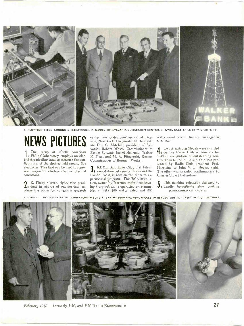
PLOTTING FIELD AROUND 5 ELECTRODES. 2. MODEL OF SYLVANIA'S RESEARCH CENTER. 3. KYDL SALT LAKE CITY STARTS TV
NEWS PICTURES1 This setup at North AmericanIt Philips' laboratory employs an elec-
trolytic plotting tank to measure the con-figuration of the electric field around fiveelectrodes. This field can be used to repre-sent magnetic, electrostatic, or thermalconditions.
E. Finley Carter, right, vice presi-L I dent in charge of engineering, ex-plains the plans for Sylvania's research
center now under construction at Bay -side, New York. His guests, left to right,are Don G. Mitchell, president of Syl-vania; Robert Moses, Commissioner ofParks; Sylvania board chairman WalterE. Poor; and M. A. Fitzgerald, QueensCommissioner of Borough Works.
9 KDYL, Salt Lake City, first televi-sion station between St. Louis and the
Pacific Coast, is now on the air with ex-perimental programs. This RCA installa-tion, owned by Intermountain Broadcast-ing Corporation, is operating on channelNo. t, with 400 watts video and e00
watts aural power. General manager isS. S. Fox_
4Two Armstrong Medals were awarded1 by the Radio Club of America for
1947 in recognition of outstanding con-tributions to the radio art. One was pre-'sented by Radio Club president Prof.Hazeltine to John V. L. Hogan, right.The other was awarded posthumously toCharles Stuart Ballaatine.
E This machine originally designed toI handle borosilicate glass cooking
(CONCLUDED ON PAGE 52)
4. JOHN V. L. HOGAN AWARDED ARMSTRONG MEDAL. 5. BAKING DISH MACHINE M >KES TV REFLECTORS. 6. LATEST IN VACUUM TUBES
February 1948 - formerly Ell, and FM RADIO -ELECTRONICS 27

This RCA Switching System consistsof a imam -on-the-air" monitorand os:il.o:cope, a waist -high :on -trot panel (enlarged view, abLve)and m xi:14 amplifier, below. Thisequipineri becomes one of thestar dard-,:ze sections of RCA'sunit -built Addeo console (tor ofpage). Any :oiribination of camera-corrro. s argil -nonitors is possib.-..- to
fit your 'articular station.

6plits6cond gledronof all television program material
FADING CONTROL
MONITOR SWITCH3 -position: program line,
either of two remotes
GAIN FOR REMOTEINPUT (#6)
REMOTE INPUTS
RELEASE BUTTONS
TALLY LIGHTSand switches for remote sync
CAMERA SWITCHES(2 rows) handle 4 inputs fromstudio and film cameras and 2remotes to permit fading, instan-Igneous switching, special effects.
TALLY LIGHTSfor six inputs
GAIN FOR REMOTEINPUT (#5)
New RCA Camera Switching Unit provides convenient,
push-button control at your video console
HERE, in one compa:t unit, is a con-trol center for your television pro-
grams. Into it can be brought as many assix video inputs-from studio cameras,film cameras, relays, and network. Oneoperator can handle the lot!
Twelve different types of switching areyour assurance of a smooth, dramaticpresentation, whatever the program.Look at the possibilities:
Your operator can Instantly switch:(1) between two local camera signals;(2) between two remote signals; (3) fromlocal to remote; (4) from remote to local;(5) from local to black screen (no sig-nal); (6) from remote t3 black (screen);(7) from black to remcte. With the spe-cial manual fader control he can, at anydesired speed: (9) fade cut local to black;( to) fade in local from black; (11) lap -dissolve between any :wo locals; (12)superimpose two locals and adjust thelevel of each. All sorts of trick effects arepossible by moving the two levers thatmake up the fader control.
RCA Studio Camera (SwitchingUnit handles up to four)
Tally lights provide an instant check onwhich input is 3eing used and whether aremote signal is being received. If re-mote sync fails for any reason, local syncautomatically tt.kes over.
The monitor in the top of the consolesection allows the operator to either viewthe on -the -air signal or preview one ofthe two remote signals.
An unusually flexible intercom switch-ing system (not shown) is included topermit private, special -group, or confer-ence communication between practicallyall personnel. All have access to programsound througri one earpiece of theirheadsets.
Here, we believe, is a switching systemthat represents the most advanced engi-neering in television station techniques.It will help you simplify television stationroutine-bring new possibilities to tele-vision programming. Be sure to get thecomplete story. Write Dept. 38-B, RadioCorporation of America, EngineeringProducts Department, Camden, N. J.
PROGRAM SOURCES
RCA's Mobil,- Studio (SwitchingUnit can handle two remotes;
TELEVISION BROADCAST EQUIPMENT
RCA Film Camera (Switching Unithandles two with 2 studio cameras)
RADIO CORPORATION of AMERICAENGINEERING PRODUCTS DEPARTMENT, CAMDEN, M.J.
In Canada: RCA VICTOR Company Limited, Montreal

FIG. 1. E. O. JOHNSON, AT THE WHEEL OF ONE OF THE SECHREST AMBULANCES, TAKES ACALL FROM THE DISPATCHER AT TRANSPORTATION COMMUNICATION SERVICE
OPERATING AN L.C.C. SYSTEMSuccess at High Point, N. C., Shows Big Field for
Limited Common Carrier Service
BY JOHN
0NE of the new fields for mobile radiocommunications, and a field that
shows great possibilities for successful de-velopment, is that of limited commoncarrier service. This is illustrated by theexperience of J. Frank Beck, owner of theBlue Bird Cab Company of High Point,N. C., and operator of TransportationCommunication Service Corporation.
High Point, a city of 39,000 population,is a furniture and hosiery manufacturingcenter. Long before taxi radio became areality, J. Frank Beck figured out that ifhe could dispatch his cabs by radio, he
* Director of Public Relations, Bendix Radio Div.,Bendix Aviation Corp., Baltimore 4, Md.
M. SITTON *
could effect a great improvement in serv-ice rendered the public, and at a sub-stantial reduction in operating cost. Thatgoes back to 1934.
It was not until 1945, however, that hewas able to test the plan in practice. Then,Bendix Radio engineers offered to set upa test system, with the idea of eventuallydesigning special 2 -way FM units fortaxicabs. The first tests were made withsurplus military aircraft units, operatingon VHF. Results showed a reduction ofN% in operating expense, compared withhis non -radio cabs. Subsequently, de-velopment work was completed on Bendixmobile equipment, and units specifically
FIG. 2. W. H. TAYLOR, DISPATCHER AT T.C.S. HEADQUARTERS STATION, RELAYS CALLSBETWEEN THE TELEPHONE LINES AND THE RADIO -EQUIPPED CARS, TAXIS, AND TRUCKS
designed for this service were put intoproduction.
Their performance was so successfulthat Beck decided to equip not only hisown cars, but to supply service to others.Under this plan, he could not only havethe benefit of radio dispatching for hisBlue Bird Cab Company, but he couldoperate his radio system at a profit byserving others.
Accordingly, he formed the Transporta-tion Communication Service Corporation,and applied to the FCC for a limited com-mon carrier license. He was assigned afrequency of 152.03 mc., with the callletters W4XLA. Under this license, cover-ing 50 mobile transmitters, he can furnishcommunications service to local indi-viduals or companies whose activities re-quire 2 -way radio, including the policeand fire departments.
His first subscriber was the J. W. Se-chrest Ambulance Service. One of theirradio -equipped ambulances is shown inFig. 1. This may seem like an unusual ap-plication of 2 -way radio, but it has provedextremely valuable in numerous instances.On one occasion, for example, a Sechrestambulance was dispatched to a rural sec-tion where two linemen had come in con-tact with high-tension wires. On arrival.the driver found that an iron lung wouldbe needed for one of the men. Knowingthat the iron lung was kept on the oppo-site side of the city, he called ahead byradio, and the equipment was in readinessat the hospital before the patient arrived!Only a few incidents of this sort were
(CONCLUDED ON PAGE 33)
FIG. 3. BENDI X MTR-3 UNIT LEAVES REARCOMPARTMENT FREE FOR LUGGAGE
30 FM AND TELEVISION

DESIGN OF STUDIO SPEECH INPUT SYSTEMSPlans Which Strike a Balance Between First Cost, Flexibility, and Maintenance Expense - Part 1
BY JOHN A. GREEN*
)0TH, efficient operation of oura modern radio stations today is effectedin a very large measure by the choice ofspeech input equipment used at the studiolocation. Better programming can be ac-complished if the equipment allows com-pletely flexible operation. and assures ahigh degree of reliability. Before a newstation is installed, or an establishedstation re -equipped, all the problemsinvolved in the complete operation shouldbe analyzed and considered very carefullywith reference to the speech input facili-ties.
It is the author's purpose to discuss insome detail typical installations of speechinput equipment suitable for the smallerstations, the larger stations, and stationswhich are operating two program sched-ules at the same time. Standard, commer-cially available equipment will be selectedto satisfy the design requirements as faras possible. In practice, it is difficult todraw the line just where one set of equip-ment will best fit, and where another ispreferable. For purposes of illustrationhere. Collins Radio units will be specified.
Gearing Equipment to Programs * Programpolicy is a major factor in the choice ofproper studio speech input equipment.Just what type of programs are planned?That is a question that the chief engineerof every new station should first ask hismanagement before lie starts any designwork on studio facilities. The chief of astation already operating has the advan-tage. in planning new facilities, of know-ing front experience what types of pro-gram material must be handled. Withthis information at hand. the wholeoperation can be laid out.
There are, of course, other factorswhich must be considered, such as thesize of the staff that will be available tooperate the station, and just how ablethis staff is likely to be. Finally, andinevitably, there is the factor of cost and.in sonic cases, a budget limitation whichcalls for simplifying the plan in order touse high -quality components, or using amore elaborate arrangement built up ofcheaper units.
In all cases, imagination must be usedin planning the installation. Imaginationis a very important tool in engineering.and when combined with sound judgmentit pays very big dividends, not only to thestation but to the engineer doing the work.There are always special operations whichmust be handled in every station. Advance
* Engineer, Collins Radio Co., Cedar Rapids, Ia.
thinking must allow for these specialswhen the equipment is originally specified.Installation of what may at the timeseem to be an extra will, in most casesprove to be economical in the end. Manyhours of rework may be saved - reworkthat usually has to be done after midnightin most instances. Many stations are re-quired to pay premium wages to the staff
be described will be related to modernstudio design practice.
The Small FM or AM Stations * Let us con-sider first the requirements of a smallAM or FM station. Fig. 1 is a typicalexample of a reasonably complete andwell -arranged plan. There is included agood size lobby, permitting the public to
CLO. I CLO.
CONTINUITYDEPT.
WOMEN
MEN
PROGRAMDIRECTOR
-70-/A-FICE
GENERALOFFICE
CLO.
CLO
OFFICE
MUSIC LIB.IISTUDIO
ACONTROL
ROOMROOM
LOBS'
AM=
STUDIOB
FIG. 1. THE FACILITIES SHOWN IN FIG. 2 ARE PLANNED FOR OFFICES AND STUDIOS SIM -LAR TO THE LAYOUT SHOWN HERE FOR A SMALL FM OR AM INSTALLATION
doing the work, phis the cost of sleep lostby everyone concerned.
Many times, all the program questionscannot be answered accurately beforeactual operation has begun. In these cases,the management must rely on the judg-ment of the chief engineer to assure thepurchase of equipment to cover whateverprogram requirements may develop. Ifthe chief engineer can foresee the majorproblems. and install equipment to meetthem, with a margin to take care of emer-gencies. lie Nv il I have performed a realservice to his company.
This paper will cover only the engineer-ing design of the speech input system. Thephysical design of the studios and thedetails of actual installation are complexsubjects by themselves, requiring separatetreatment. However, typical examples to
observe the different shows produced atthe station, with the minimum of inter-ference with the staff. The view into boththe studios as well as the control room isunobstructed. Office space is provided forthe manager, program director, salesdepartment, continuity department, andfor the general office. Sufficient closetspace is allowed for storage of stationery.sales promotion material, operationalsupplies and records. A music library.handy to both the continuity departmentand to the control room, allows storagefor transcriptions and records. Officespace is provided for the chief engineer.and connecting to this office is the workshop, a very necessary item in every sta-tion design. A well-equipped shop is a realincentive for the engineers to keep theequipment in shape, and to build new
February 1948 - formerly FM, and FM RADIO -ELECTRONICS 31

equipment, designed for specific opera-tional requirements, in less time and atless expense than it can be obtainedoutside.
Now let us assume typical operating
STUDRSA
I 1.11C.1
I MIC.26 )
chestra, a drama or so plus, of course, thestandard newscasts.
4. A few remote pickups will be in-cluded in each day's operation.
5. Provision must be made for con -
212 B2 SPEECH INPUT CONSOLE
I SPAREI PIC. 1
I MONI1SPKR.
I AIR(LIGHTS
L _ _ _ J
r STUDIO BMIC 1
SRCrA'1
ZoaraoL MalMICA I
T.T. 1 4-1-11-11-E]
T.T. 2
PROMMON.
SPKR.
AIRLICH
AUX.MON.
SPKR.
T09 TEL.
REMOTE
7 Col cry- 1
MONSPKR- - -
E C.
PRE AMP
PRE AMP
PRE AMP
PRE AMP
OPSPARE
PRE AMP 1
6PSPARE
PRE AMP 2
rri- 9 PAIR"9-1 CABLE
-CIF-
EIDUAAL7ZERAMP.
Q.nc.
6101
NETWORKISOLATION
PRE AMP
PPE AMP
El CI
9 POSITIONPUSHBUTTON
REMOTESELEC.SW.
L
El El
PROGRAMAMP
PAS'it MgtPUSH BUTTOI
SELEC. SW.
PRO MON.PHONES
MON. AMP.
each requirement, and allow for sonicspecial situations.
The 18 -hour operation requires that theequipment be reliable in performanceover a long period of time. Maintenance
MON. AMPPHONES
117N-4REPEAT COIL
OHf6s6M
OtI=14 E1)6?:1
I N
OHM -m --m
'30:
IN OUT
1 -
.. El ElOHM W OHM
Ge :M°°911=1-
BEL'20. OUT
r_..ii000m _0 0 0,600mmBRIDGING OUT
IN
ET
ElEl
61UTILITY
ISOLATIONAMP.
PRESTO218A
RECORDINGAMP
6 faNvE IL!
OLINES TO
TRANSMITTER
-ft-E)--.- CUTTERCUT TER 2
ireai`,11.15
MON. SPKR. JACKS m
of tir
t
MULTIPLE JACKS409 T-1
AMP.POWERRIPPLY
2740-2 OR2740-5
CONSOLErRELAY UNIT
:2
112 B-1SWITCH &
FUSE PANEL
RACK 1
409U- I OR409U-2
CONSOLEPOWER SUR
ao
iiggO 4
112 B-1SWITCH&
FUSE PANEL
115 V.60,1,A C SOURCE
FIG.2. WHILE THIS PLAN MAY BE MODIFIED
conditions which the equipment must heable to handle:
1. The station will operate an 18 -hourschedule each day.
R. A large part of the programs will betranscribed or recorded.
3. There will be a few studio showseach day, limited perhaps to a small or -
RACK 2
115V. 60 T.POWER LIN
a n222(a .c
as WZrjZ
600014.1
6%AUXILIARYMON AMP.
FMFp DiED
6 PR. SPARE JACKS
KEY
El JACKS (PAIR)
El GAIN CONTROL
El VOLUME INDICATOR
E REPEAT COIL
Ej KEY SWITCH
INTIFIE;ACK
PROGRAM ORAUDITION
E RSLOUD
SPEAK
El El
Fl
El E/
SALESOFFICE
CONTINUITYDEPT.
MANAGERSOFFICE
PROGRAMDIRECTOR
CH. ENG.OFFICE OR
SHOP
MUSICLIBRARY
IN ITS DETAILS. IT REPRESENTS THE REQUIREMENTS FOR A SMALL, UP-TO-DATE STATION
nection to a net work, even though opera-tion is to be independent initially.
6. Some recordings must be made eachbroadcasting day for use not only on tlnair, but for the reference library and forauditions. With these operational points.consideration must be given to just whatthe equipment must be able to do to cover
is a necessary item in every station'soperation, but this maintenance can beBone only during the six hours the sta-tion is off the air. This requires that allcomponents in the equipment be readilyaccessible for inspection, and that a mini-mum amount of tear -down is required forservicing each part of the entire equip -
32 FM AND TELEVISION

ment. Six hours can pass rapidly whilehunting trouble.
Provision must be made for at leasthigh -quality transcription turntable as-semblies, preferably equipped with uni-versal -type pick ups. This will allow thestation to use both vertical and lateraltranscriptions and records. It may be thata third transcription turntable should beprovided so that, at times during the daywhen the recorded load is high (for exam-ple, singing commercials) this extra turn-table can be used to help simplify theoperation. and to eliminate errors due toconfusion.
To produce local studio shows, prop-erly. it is necessary to choose the righttype of microphones and stands, so thatthe microphones can he used in a varietyof situations to facilitate program con-tinuity. Good monitor speakers and anample number of studio warning lightsare also important to insure trouble -freestudio productions. The monitor speakerswill allow the performers to hear what isgoing on, and the warning lights arenecessary as a guide to people walking inand out of the studios.
The network connection, in most cases,can be handled to hest advantage asanother remote connection into the studiospeech input console. That is the mannerof connection suggested for this particularlayout. Facilities for auditioning shows.
cueing records, and talking -in remotesare necessary items for every studiospeech input system. Recording on -the -air performances for reference or foraudition is another important part ofradio operation today. Good recordersshould be used. The first cost is greater,but they will soon pay for themselves inthe quality and reliability of recordingsthat can be made with them.
Fig. 4 is a block diagram prepared torepresent, or perhaps better to specify.the equipment required to do the job forthis theoretical station operation we haveset up. The equipment necessary for thebasic operation is provided, plus someequipment to handle the specials whichcome up every now and then at anystation.
Two microphones in Studio A, and onemicrophone in Studio B are normally con-nected to the console. In the control room,one microphone and two transcriptionturntables are normally connected to theconsole. An extra receptacle in each studioand in the control' room, are terminatedat the jack strip on the racks, so thatextra equipment can be connected andpatched into the system as required.There is a monitor speaker in each studio,and in the control room and lobby. Warn-ing lights are required outside each studioand the control room, so that people willnot walk in when the microphones are
open. Audio circuits throughout the com-plete installation are brought up onjacks to insure flexible operation of theentire equipment under all conditions ofprogram loading. Two rack -mountedpreamplifiers are used in the system.These permit the operation of any com-bination of additional microphones andtranscription turntables in the studios orin the control room. The outputs of thesepreamplifiers are brought into the consolein the same fashion as a remote would behandled.
A program equalizer is provided for usewith telephone circuits on remote pickups.This provides equalization of both thelow and high frequencies. An amplifier isrequired in conjunction with the equalizerto make up for the insertion loss. A secondamplifier is included as a utility amplifier,or as an isolation amplifier in the networkcircuit. Plate and filament power for theamplifiers is obtained from a rack -mountedpower supply.
All AC power for the studio installationis routed through the two circuit -breakerand fuse -panel assemblies, so that eachand every piece of equipment is sep-arately fused and protected from damageshould it or other pieces of equipment fail.
Part 2, describing the individual units forthis installation, will appear in a forth-coming issue.
COMMENT ON DUPLICATION
THE First continent we received from aset manufacturer came from Arthur
Freed, general manager of Freed RadioCorporation. This company was one of thefirst to produce FM receivers, and is stillthe only one to manufacture FM -AM setsexclusively. Just back from a coast -to -coast survey of FM dealers, Mr. Freedhad this to say:
Widespread benefits to the public andto every segment of the radio industrywill result from the network -union agree-ment to end the ban on duplicating livemusical broadcasts on Frequency Modula-tion channels.
Until yesterday's agreement was reached,retailers and distributors throughout thecountry who have absorbed more than amillion FM radio sets manufactured lastyear were generally pessimistic about theFM radio sales picture. The increase in thesales of FM radios expected by the dealersnever fully developed because of the pub-lic's disappointment with the limitedentertainment fare and the poor quality ofmusical broadcasts which FM stationswere obliged to offer. This condition wasforced on FM broadcasters because oftheir inability to duplicate important net-work shows, and their complete relianceon recorded music. Now the promises thatFM made to (healers and to the public canbe realized. Live musical shows on FMstations will provide a quality of reception
that standard broadcasts or recordingscould never achieve because they haveless than half the tonal range possible onFrequency Modulation broadcasting. Per-haps the most important factor in increas-ing FM sales will be the'opportunity nowafforded to let prospective customers hearthe difference between AM and FM recep-tion of the same program. In this way,people in metropolitan areas who say,"Oh. I get perfect reception on my AMset," will have a chance to hear how farfrom perfect is the best AM reception.
When the public has an opportunity tohear the immeasurably better musicalentertainment that live FM makes avail-able, there will be a great increase in retailactivity on FM radios. Moreover, highfidelity FM broadcasting will enable deal-ers to sell better instruments and increasetheir unit of sales. There can be no doubtthat the public will want to take advan-tage of this finer radio reception, and thatthey will be willing to pay for more expen-sive sets. For the first time, the publicwill be able to recognize a difference in thereception quality of radios offered to them.
Broadcasters, too, will benefit greatlyfrom the decision to duplicate programson AM and FM channels. At present, aconsiderable number of FM independents,many of them ex -GI's, are having diffi-culty to meet fixed charges because thepoor quality of most FM programminghas not enabled them to develop audi-ences which will attract advertising dol-
lars. Now, large numbers will be able tosecure network affiliations and audience -building programs.
Independents who cannot negotiateaffiliations with existing networks imme-diately will associate themselves, beforelong, with new radio networks which aresure to be organized. Networks, con-versely, will not be so dependent on a fewpowerful \M stations.
OPERATING AN L.C.C. SYSTEM(CONTINUED FROM PAGE 30)
necessary to convince other subscribers ofthe value of T.C.S. mobile radio.
The main transmitter is a Bendix typeMRT-1E, with a biconical antenna in-stalled on the 14 story Southern FurnitureExposition Building. The remote controlpoint, Fig. 4, is at the T.C.S. office. Allthe mobile units Bendix type MTR-3's,as illustrated in Fig. 3. This is a verycompact design, small enough to bemounted in a rear compartment withouttaking up space needed for luggage. Themaximum range of the system is 25 to 40miles.
At present, there are 49 companieslicensed as limited common carriers. Butthis is only a start. This group will in-crease rapidly in number as others realizehow effectively one radio system canhandle 2 -way communications for manydifferent kinds of local subscribers. Hereis an undertaking that should appealparticularly to radio servicemen.
February 1948 - formerly FM, and FM RADIO -ELECTRONICS 33

1. BROOK HIGH-FIDELITY AMPLIFIER. 2. UTC PROFESSIONAL AUDIO TRANSFORMERS
3. HARVEY RADIO FM TUNER AND ALTEC SPEAKER IN A CUSTOM CABINET INSTALLATION
4. 'MEISSNER FM -AM CHASSIS AND AMPLIFIER FOR CUSTOM SET -BUILDERS
6. LEFT: HARVEY RADIO'S FMSWEEP GENERATOR AND OSCIL-LOSCOPE FOR VISUAL ALIGN-
MENT OF FM RECEIVERS
7. RIGHT. PHILCO TEST UNITFOR CHECKING TELEVISION SETPERFORMANCE WITHOUT THENEED OF ACTUAL RECEPTION.IT SUPPLIES TEST GRID, SHOWN
BELOW, ON PICTURE TUBE
ITEMS FOR DEALERSAM -FM Program Duplication and
Creating a Vast New Business in
r111 111 network programs nowwbroadcast
over affiliated FM stations,and a steady expansion of television trans-mission under way, 1948 will set a newrecord of profits for dealers and service -
11 11 who undertake to capitalize on theopportunities which are being created.
Already, in areas where good FM orTV programs are available, sales curveson FM and TV sets are climbing steadily,with AM sales definitely dropping off. Thesteeper the up grade on the former, thesharper the down grade on the latter.
Conditions vary in different localities,but the trend is the same, differing only indegree.
The new business, whatever its volumein any given area, is divided into theseclasses: 1) standard FM and TV receivers,i) custom-built chassis installations withvarious combinations of phonographs,noise -suppressors, wide -range amplifiers,and high-fidelity speakers, and 3) FM andTV installations and service work.
The importance of this changing aspectof sales and service, and the trend is well
5. BENDI X FACTOMETER FOR PRE -CHECKING RECEPTION

AND SERVICEMEN
More FM and TV Stations Are
High -Profit Equipment Sales and Service
established, lies in 1) the increasinglytechnical nature of the new equipment.i) the much higher margin of profits to berealized from the larger units of sale, and3) the decreasing ratio of legitimate serv-ice charges to the original cost of theequipment repaired.
As an indication of this development,some of the new equipment and test in-struments are illustrated on these pages.Each item was selected because it playssome part in the new business created byFM and television.
Space does not permit detailed descrip-tions. However, complete technical in-formation can he obtained by addressinga postcard to the New Business Editor.FM AND TELEVISION Magazine. Give thenumbers appearing under the illustrationsof items in which you are interested.
In addition, our New Business Editorwill be glad to answer specific questionsor to be of assistance in any way in con-nection with problems concerned withFM and TV sales, servicing, and customset -building.
t k. * 14' It :s.*, ..;%30
8. RCA SWEEP SIGNAL GENERATOR FOR SERVICING FM SETS. -9. HICKOK OSCILLOSCOPE
10. FISHER DYNAMIC NOISE SUPPRESSOR AND POWER AMPLIFIER FOR CUSTOM SETS
flICTIKSCAATORY
014
.ttaZaga*z..1,.r Wiiiija,.kreere eeeee 4110G1
11. ALTEC-LANSING AMPLIFIER. 12. SIMPSON'S METER ASSEMBLY. 13. PRECISION TESTER 14. 3ELOW: KAY FM -TV INSTRUMEN1,

DISCUSSION OF FM PROPAGATION TESTSText of a Supplementary Brief Concerning Norton -Allen Testimony before the FCC- Conclusion
What Mr. Allen (lid was to analyze thehigh -band signals on the hourly medianbasis for all 7 months of the Southamp-ton tests, except the month of Noveber,so that when he averaged his figures for7 months the result reflected the signaldrop -outs for only HO of the time (Fig.1); and when he averaged the figures for5 months, not including November (Fig.4), the drop -outs were not reflected at all.
On the other hand, Mr. Allen appliedthe minute -by -minute method of analysisto the low band transmissions for all 7months, except July and August, so thathis averages reflected the drop -outs for 5of the 7 months and 3 of the 5 monthsinvolved in Figs. 1 and 4, respectively.
A comparison of two sets of recordingson two different bases of analysis makesthe resulting conclusions absolutelyworthless.
Inadequacies of Test on High Band * A 725 -wattraiismit ler does not give a strong enough
signal at 70 miles to permit accurate testsof field intensities to be made. Such asignal is so near to the noise level that evenslight drop -outs get into the noise area,and the depths of the drop -outs cannot bemeasured. Hence the recordings on suchlow power do not give the same picture asrecordings on power sufficient to keep thenormal signal well above the noise level.
The following quotation from a letterin the Commission's files, dated August15, 1946. from Slowie (dictated by Allen)to Poppole of WOR, indicates that Allenappreciated the unreliability of the lowpower signals for testing purposes:
"There are times at Southampton andat Laurel when the signal levels providedby the 1 -kw. transmitter are too low forrecording purposes. The substitution ofthe high -gain antenna for the presentdoublet will greatly increase the valueand reliability of the recordings, andanything which you can do to expeditethe change will be greatly appreciated."
The high -gain antenna was not put intoservice until October 10, 1946, and theSouthampton tests were discontinued onNovember 20, 1946. though the tests atthe other three geographical points werecontinued through May, 1947.
Thus an additional defect in the Allenreport and findings is that the recordingson the 2 hands were not comparable, thesignals on the high hand being too weakfor even reasonably accurate measure-ment of the fluctuations in signal strength.
Nor was the apparatus used by the
BY MAJOR EDWIN H. ARMSTRONG
Commission in the Southampton record-ings accurate enough to give good meas-urements, especially of the weak signalson the high band. In that apparatus therecorder armature was in the plate circuitof a vacuum tube amplifier, whose platecurrent was controlled by the AVC circuit.It is notorious that in such apparatusthere is a "bug" known as a "floatingzero," which makes it difficult or impos-sible to measure weak signals accurately.In the work at Westhampton Beach thesame type of apparatus was used at theoutset, though considerably improved bya crystal -controlled oscillator in thereceiving set; but it was found, in spiteof the transmitter power of 100 kw.. thatthe floating zero still made the recordingsof drop -outs inaccurate. The floating zerowas finally eliminated by insertion of acrystal rectifier, by which, as alreadyexplained, the rectified intermediate -frequency currents of the receiver weremade to drive the recorder armaturedirectly.
Discrepancy Between Recordings and Charts *analyzed the Commission's recordings ofthe high band transmission for the 5 -month period from June to October,1946, in an effort to measure the amountof time during which the signal was belowthe .5 -microvolt level. Because the record-ing tapes were run at only 3 ins. perhour (as compared with 6 -in. and 12 -in.per hour speeds employed at Westhamp-ton Beach), and because the analysis hadto be made in a cramped part of thescale, the mechanical job of counting thetime intervals was very difficult. I be-lieve, however, that the result that I ob-tained is accurate to within 20%.
I found - by counting the intervals(luring which the signal strength wasshown by the recordings to have beenbelow the 5 -microvolt level - that thetotal amount of time during the 5 monthswhen that condition appeared to exist wasabout 8.6% of the total time covered bythe recordings. Allowing for a 20% marginof error, the range would he from about7% to about 10%.
These figures compare with Mr. Allen'sfigure of %oths of 1% on his chart (Fig. 1).My findings, in other words, show that theaggregate duration of the drops below the5 -microvolt line for the high -band signalwas 35 to 50 times as great as Mr. Allenshowed on his Fig. 1.
By his Errata sheet 6 Mr. Allen has nowcorrected the .2% figure, changing it to
; - increasing his original figure by amere matter of 1250%.
I do not suggest to the Commission thatmy figure of 7% to 10% for time below the5 -microvolt level, as obtained by anexamination of the high -band recordingsmade at Southampton, is a figure that canbe relied on to show the extent of fadingon the high band. I (10 not think that anyfigure derived from the Commission'srecordings can be relied on, because Ibelieve that the recordings themselves areunreliable, for the various reasons de-veloped in this brief.
Errors on the Face of the Charts * it is not at allclear how Mr. Allen got from the record-ings to his final charts, since the finalcharts purport to show the overall resultsover periods of .1 and 7 months and do notdisclose any of the detailed plotting bywhich he got his hourly median and otherfigures and put them together into thecomposite picture which the charts pre-sent. Whatever errors may have beeninvolved in the intervening work cannothe determined, since only the underlyingdata and the final charts have beenavailable.
But if the charts themselves are fairspecimens of the whole job of analysis,then they indicate that the analysis andthe conclusions cannot be relied on, sincethe charts show errors on their face, andeven mathematical absurdities.
For instance, Fig. 4 shows that thelow -band recordings over a period of 5months dropped below the 5 -microvoltline for 10% of the time, i.e., fOr intervalstotaling up to of one month of testingtime. Fig. 1, on the other hand, showsthat for 7 months the low -hand signaldropped below the 5 -microvolt line for16% of the time - or for intervals total-ing up to 1.12 months of testing time.Since the 5 months were included in the7, this means that the addition of 2months increased the time intervalsbelow .1 microvolts from IA of a mouthto 1.12 months, an increase of 63' ooths ofa month.
This means that in the added 2 monthsthe time during which the signals on thelow band dropped below 5 microvolts was31% of the total testing time. This figureis not only absurdly high. but it is quite
(CONTINUED ON PAGE 63)
The Errata sheet was handed to me by Mr. Allenafter I had pointed out to him some of the errors Ihad noted. It is dated November 26, 1947, consists of3 pages, and is headed " Draft."
36 FM AND TELEVISION

FIG. 1, ABOVE: JACK MCCUL-LOUGH, LEFT, AND BILLEITEL, WITH ONE OF THENEW 3X12500A3 TRIODES.BELOW: 6 -BAY TURNSTILEON THE El MAC PLANT AT SANBRUNO, NOW SET UP FOR
TEMPORARY USE
11,155.510111IRSINF"
111ll HE
50 KW. OUTPUT ON 88 T0108 MC.An Indirect Approach to High -Power FM Transmitter
Design Produces a Practical Solution
BY ARTHUR ARIGONI
0\ April 23, 1947. KSBR. of RadioI )iablo, Inc.. first went on the air withkw. of power at 100.3 inc. The site is
probably the worst conceivable FM loca-tion ever used, as San Bruno has an alti-tude of only 8 ft. above San FranciscoBay. The (i-hay turnstile antenna, as il-lustrated in Fig. 1, has an effective heightof 80 ft. Hills 1.000 ft. high and only 3miles away stand between the transmittersite and the metropolitan San Franciscoarea 12 miles north. Even so, a satisfac-tory signal is delivered to San Franciscoand the Marin County suburbs north ofthere. Eastwards. 2,000- to 3,800 -ft. hillsseparate the interior valley communitiesof Sacramento and Stockton from thetransmitter site. In spite of these handi-caps, good signals are delivered at airlinedistances of 60 to 80 miles.
Coverage with High Power * It is apparentthat even with au antenna location asmediocre as could be found, high -power100 -me. FM can supply good signalsthroughout a broad area. High power froma better antenna location is certain tooutdo present AM coverage by a large
*Chief Engineer. Radio Diablo, Ine., San Bruno,Calif.
nmrgin. This will shortly be demonstratedwhen the KSBR transmitter is taken toits permanent site on the summit ofMount Diablo, a mountain which over-looks the entire central valley of Cali-fornia as well as the San Francisco bayarea from a 3,800 -ft. altitude. From thisideal point, fully adequate FM signals willbe made available to more than three mil-lion people.
Mount Diablo is unique in its commandof great areas of land. From its peak. 39 ofCalifornia's 58 counties can be seen, as can
MOD.SOW
1 ST I. A. 2NOTWOP.I.A.FOUR
4 XSOOF 3X2500 A33.5 5W. 13 KW
P.A.TWO
3x12500 A350 KW.
04 000 V.
FIG. 2. 60 KW. FROM 3 STAGES
Mount Lassen. Mount Whitney, and HalfDome in Yosemite. The mountain, whichstands roughly at the focal point of aterrestrial parabola. played a vital part inthe early development of northern Cali-fornia. Due to its visibility over largeareas, it bears on its top the main pointfrom which survey lines were determinedfor the entire northern part of the state.It will be in the spirit of the mountain toserve again as a pioneering landmark --this time for the dials of northern Cali-fornia's radio receivers.
Operations by a number of broadcastersin the old FM band demonstrated that lhigh -power is the way to assure listenersof sufficient signals at their receiver termi-nals. and 2) types of power tubes used atthe 42 to 30 me. were operating near theirupper useful frequency limit. The designand development of KSBR's transmitterwas undertaken by Eitel-McCullough.Inc.. manufacturers of Eimac tubes, as aproject directly related to development ofnew power tubes capable of operatingthroughout the new hand at powers inthe 50 -kw. range.
Transmitter * As shown in the block dia-gram of the KSIllt transmitter. Fig. 2, a30 -watt REI, modulator drives a 3 -kw.intermediate power amplifier consisting of4 Eimac 4X300F tetrodes. This drivesa 13 -kw. IPA with two grounded -gridEimac 3X2500A3 triodes in push-pullwhich. in turn, drives the final power am-plifier, employing two push-pull grounded -grid Eimac 3X12500A3 triodes. The IPAstages are illustrated in Figs. 3 and 4.Their experimental appearance comesfrom the fact that they were convertedfor the purpose from existing pieces oftest equipment. but final installation atopMount. Diablo will see them rebuilt and.to a certain extent, condensed in size.Examination of the general view of thetransmitter illustrated here, however, willgive some indication of the remarkablysnall size of the complete unit. especiallyby comparison with a 30 -kw. AM trans-mitter or even one of the few 50 -kw. trans-mitters to reach operational status in the01(1 42-30 Inc. FM band.
The gear which contains most of theengineering departures is the 50 -kw. finalamplifier, Fig. 10. One of the 3X12500A3triodes is shown in Fig. 6. This is the newtube that came out of the KSBR develop-ment. While it was originally intendedspecifically for the task of producing 25kw. with high efficiency at FM frequen-cies. it has proved its suitability for nu-merous other applications as well. It con-sists of 4 units of the 3X2500A3 type,assembled on a common mounting. Fila-ment and grid terminals of the units areinterconnected by low -inductance disks.Grid and filament contact fingers are in-tegral with the tube, to permit a socketconsisting of simple concentric ringsagainst which appropriate clamps hold the
February 1948 - formerly FM, and FM RADIO -ELECTRONICS 37

tube. The mounting is so designed thatindividual units can he taken out at thefactory and replaced.
Tube Design Considerations * Multiple tubes.made cruel a numher of small factory -assembled mass-produced units, have sev-eral advantages over single high -powertubes of power ratings equivalent to thetotal output of the asseinbly. :1 tube mustbe short compared with its operatingwavelength if effective use of electrodeareas is to be made. At high frequencies.this requires large electrode diameters insingle -unit, high -power tubes.
Good over-all efficiency at high fre-quencies requires the use of low operatingvoltages, hence, small inter -electrodespacings. Small diameter grid wire andlarge effective filament area are also indi-cated. While it is not impossible to sup-port a closely -spaced grid -filament struc-ture answering these qualifications, it iscertainly difficult and costly. Supportrods, insulators, and construction of thatkind are a liability not only in perform-ance but also in production.
Great weight is another disadvantage ofsingle -unit designs. Heavy -walled copperanodes and large cooling -fin assembliesare usually necessary. making a single -unit tube of 12.5 -kw. plate dissipationcapability weigh 100 to 200 lbs. Bycomparison, the 4 -unit tube has a weightof 32 pounds. This light weight of the3x12500A3, combined with the simplecontact arrangement. speeds up tubechanges tremendously and makes generalhandling very easy.
Multi -unit tubes gain their greatest ad-vantage in the fact that they eliminateany compromise with performance in pro-ducing high power at high frequencies. Inthe case of KS1312, this makes possibleperformance in the 50 -kw. stage equal tothat of the preceding amplifier, the push-pull pair of 3x2500A3 triodes whose per-formance at 12.5 kw. was already known.
FIG. 3. FIRST IPA DELIVERS 3.5 KW. WITH FOUR 4x500F TETRODES IN PUSH-PULL PARAL-LEL, AT 72 PERCENT EFFICIENCY. FIG. 4. 2ND IPA DELIVERS 13 KW. FROM TWO 3x2500A3'S
FIG. 5. THE COMPLETE 50 -KW TRANSMITTER
TABLE 1- OPERATING CONDITIONSFirst IPA
(Four 4)(500A)Second IPA
(Two 3X2300A3)Power Amplifier
(Two 3X12500A3)
D -C Plate Vetage 3507 volts 4000 4000D -C Plate Current 1.3 amps. 3.5 13.5D -C Grid Vetage -200 volts -500 -500D -C Grid Current .075 amps. 0.5 1.8D -C Screen Voltage 500 voltsD -C Screen Current .055 ma.Driving Power (Approx.) .050 kw. 3.21 12.51Useful Power Output 3.5' kw. 131 50
1Discrepancies between driving power and power output of preceding stage are due to lossesin coupling circuits.
BUILT FOR EXPERIMENTAL PURPOSES
Mechanical Design * Two 1i -in. conductorson 14 -in. centers, Fig. 7, comprise thecathode tank circuit of the 50 -kw. am-plifier. These conductors are entirelyhoused in all oval shield. Fig. 8. with IA -in. spacing from the conductor. The tankcircuit is shown ill Fig. 7 without theshield. Both the conductors and the shieldare of sheet copper.
The cathode tank circuit is tuned bymoving a shorting plate which contactsboth the shield and the tank conductors.The shorting plate is illustrated in Fig. 9.It is moved by 4 leadscrews linked to-gether by chain and driven from a panelcontrol by means of a set of bevel gears.The cathode tank circuit is about of awavelength long at resonance.
The amplifier is divided into two sepa-rate sections by a 24- by 36 -in. dur-alumin plate. /38 in. thick. which serves asan isolating shield between plate and
38 FM AND TELEVISION

cathode circuits. The cathode -tank shieldis firmly secured to the lower face of thedural shield. Bias leads into the amplifier
FIG. 6. THE El MAC 3:12600A3 TRIODE
are small, flexible coaxial cables. Theseshielded leads prevent leakage of RF fromthe plate circuit into external parts of theamplifier.
The plate tank circuit and the cathode
FIG. 10. THE FINAL AMPLIFIER UNIT
parallel at the top, the two loops feed asingle open -wire transmission line to theantenna. The coupling loops are fastened
or down to adjust the amount of couplingwith the plate circuit.
Located on the antenna transmissionline near the point of its connection to the
FIG. 9. SHORTING PLATE TUNES TANK
coupling loops is a single stub, adjustableas to length and placing. This tunes outthe reactance of the loops. _
Table 1 gives typical operating condi-tions for the 50 -kw. stage. The amplifierdelivers 50 kw. easily at 100.5 mc. and hasproduced a power output of 58 kw. with-out exceeding any tube ratings. Maximumoutput within the tube ratings has not
FIG. 7. CATHODE TANK CIRCUIT IN OUTER SHIELD, WITH SHORTING PLATE IN POSITION. FIG. 8. PLATE TANK CIRCUIT
tank circuit are quite similar. Spacingbetween conductors and the shield is 1 in.in the plate circuit, however, because theplate tank can have a higher surge im-pedence than the cathode circuit. Theplate circuit is slightly more than wave-length long at resonance when shuntedwith the output capacitance of the ampli-fier tubes. The plate -tank shorting plateis similar to the one in the cathode circuitexcept that it has a larger outer dimensionto match the larger shield. Tuning is alsoachieved with leadscrews. Fig. 8 shows theplate tank circuit.
Two loops take power from the platecircuit. They enter the plate tank circuitfrom above and project through slots inthe shorting plate into the field aroundthe platetank conductors. Connected in
at the top to a sheet of Teflon which hasits own leadscrews. and can he driven up
SCHEDULE OF PAPERS ATIRE CONVENTION, N. Y.
Following is the schedule of papers tohe presented during the I.R.E. Conven-tion, New York City, March 22 to 25:
MONDAY AFTERNOON, MARCH 22Frequency Modulation - Systems I -Navigation Aids - Antennas
TUESDAY MORNING, MARCII 23Systems II - Amplifiers - Passive Cir-cuits - Tubes I - Antennas II
TUESDAY AFTERNOON, MARCH 23Superregeneration - Transmission - Nu-clear Studies - Tubes II - Components
been checked but it would probably ex-ceed 60 kw.
& Supersonics
TUESDAY EVENING, MARCH 23Nuclear Studies
WEDNESDAY MORNING, MARCH 24Tube Applications
WEDNESDAY AFTERNOON, MARCH 24Television - Tubes III - Measurements
THURSDAY MORNING, MARCH 25Computers I - Broadcasting & Record-ing - Propagation - Tubes IV - Meas-urements II
THURSDAY AFTERNOON, MARCH 25Computers II - Microwaves - Receiv-ers - Active Circuits
February 1948 - formerly FM, and FM RADIO -ELECTRONICS 39

THE MICROWAVE HANDBOOKChapter 2: Why Microwave Equipment Departs So Radically from Conventional Radio Designs
BY SAMUEL FREEDMAN
2.1 Reactance at Microwave Frequencies * Everycircuit, no matter how simple. containsinductance, capacitance, and resistance.It is physically impossible to constructpure inductance, capacitance, or resis-tance. An inductor must also possess somecapacitance and resistance. Similarly, acapacitor must have inductance and resis-tance, and a resistor must have inductanceand capacitance. These properties existbecause of spacings, connections, and thecomposition of conducting materials.
While microwave circuits obey all themathematical laws of low -frequency ACcircuits, some amazing effects result from
(-2)
..?/rf ('
where X = reactance in ohmsf = frequency in cycles
and C = capacity in faradsThus, while the reactance of a capacitormay be very high at low frequencies, onmicrowaves the value Xc drops to a pointwhere the capacitor is virtually a shortcircuit.
The total reactance or opposition tothe flow of AC is
X = (3)Note what happens to the value of X in a
FIG. 5. RESISTANCE AND PENETRATION OF VARIOUS METALS AT MICROWAVE FREOUENCI ES
the extremely high values of microwavefrequencies. For example:
A resistor offers opposition to bothAC and DC currents. An inductor, how-ever, has relatively small resistance toDC, but a high resistance to AC, increas-ing with the frequency. This is in ac-cordance with the equation
XL = 2rf (1)where XL = reactance in ohms
f = frequency in cyclesand L = inductance in henries
From this it can be seen that, while theinductive reactance of a coil may be verysmall at low frequencies, on microwavesthe value XL increases to a point wherethe coil is virtually an AC insulator.
On the other hand, a capacitor offersmaximum resistance to DC, but a low re-sistance to AC, decreasing with the fre-quency. This is in accordance with theequation
circuit comprising an inductance of 10millihenries and a capacitance of .01 mfd.as the frequency is varied from 10 kc. to10,000 Inc.
Frequency XL (Ohms) Xc (Ohms)10 kc. 6'28 159,154
100 kc. 6.283 15,9151 mc. 62,832 1,591
10 inc. 628,320 159.1100 mc. 6,83,400 15.91
1,000 mc. 62,832,000 1.59110,000 inc. 618,39.0,00( .1591
Thus, the value of X, predominantly ca-pacitive at low frequencies, becomes pre-dominantly inductive at the upper end ofthe frequency range. It is this effectwhich creates the need for completely newconcepts of radio circuit design at micro-wave frequencies, and opens the way tonew methods and applications.
This change comes about because 1) at
the lower frequenci,. inductance andcapacitance are lumped or concentrated inindividual components, while at micro-waves they are distributed, and e) thephysical dimensions of low -frequency com-ponents are small compared to the wave-lengths employed, in contrast to micro-wave circuit elements which approach oreven exceed the operating wavelengths.
2.2 Skin Effect * Whereas DC flows in theentire cross-section of a conductor, theflow of AC tends to concentrate at theouter skin of the conductor until, atmicrowaves, a solid conductor can be re-placed by a tube of the same outside diam-eter and a wall thickness of a few millionthsof an inch.
This concentration of high -frequencycurrent toward the surface of a conductoris called skin effect. As a result of thiseffect, a conductor of large cross-sectionand low DC resistance has a relativelyhigh resistance to microwaves. However,the resistance to microwaves would bereduced considerably if the same volumeof metal were rolled into a tube with awall thickness of perhaps .00005 in.
Since it is desirable to reduce the ACresistance to the lowest figure possibleper unit length, and since the skin effectprecludes any benefit from the cross-section of a conductor, it is necessary toemploy a conducting surface layer of thehighest conductivity possible.
As far as electrical performance onmicrowaves is concerned, the compositionof the core of a conductor makes little orno difference, as long as the surface isplated with a low -resistance metal. Sincethe volume of the surface layer is small.it is common practice to use gold or silverplating on any metallic, plastic. or othercore material. Typical gold plating is inthe order of 50 milligrams per squareinch.
Five different metals are used currently.either by themselves, or plated with sil-ver or gold. These are:
ETAI.
Brass
Aluminum
Copper
Silver
Gold
ADVANTAGES
Rigid, holds toler-ance, inexpensiveLight in weight
Good conductiv-ityExcellent conduc-tivity when brightGood conductiv-ity, does not cor-rode
DISADV A STAGES
Heavy, low con-ductivity.Special alloy(miredMechanicallyweakCorrodes readily,expensiveExpensive
Fabricators are also investigating thepossibilities of plated or sprayed glass,plastic, paper, and other materials. Fig. 5is a calculated graph comparing 5 princi-
40 AND TELEVISION
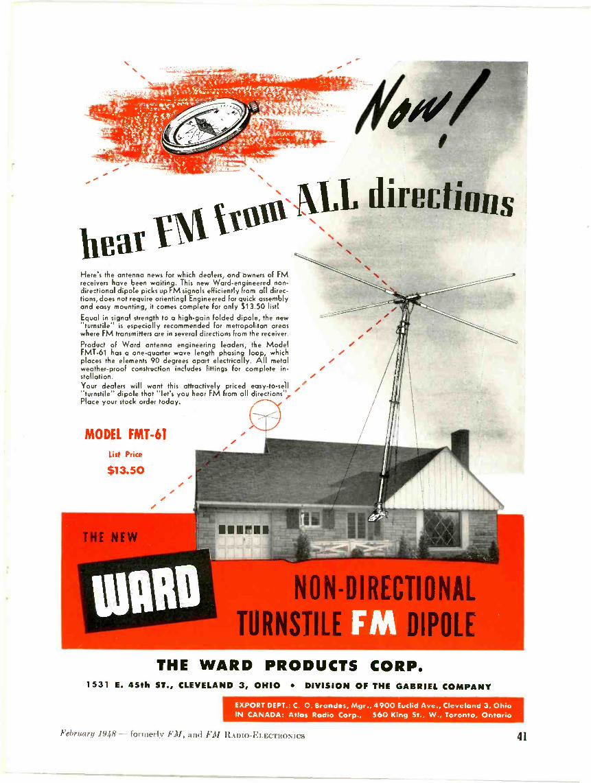
N%
%, - gjai.` =' 't.'r,Iketar -A
"i i x -,1,1?..0itilWe'V'7":75rq.-t-atcl.14. c
rottre. 110(11 f 4"9.. l 1.1.- ...:.
j .5aPIPV
11Pat YMIVALL dirPC S
Here's the antenna news for which dealers, and owners of FMreceivers have been waiting. This new Ward -engineered non -directional dipole picks up FM signals efficiently from ail direc-tions, does not require orienting! Engineered for quick assemblyand easy mounting, it comes complete for only S1 3.5C listl
Equal in signal strength to a high -gain folded dipole, 'he new"turnstile- is especially recommended for metropol tan areaswhere FM transmitters are in several directions from the receiver.
Product of Ward antenna engineering leaders, the ModelFMT-61 has a one -quarter wave length phasing loop, whichplaces the elements 90 degrees apart electrically. All metalweather-proof construction includes fittings for complete in-stallation.Your dealers will want this attractively priced easy -to -sell"turnstile- dipole that "let's you hear FM from all directions',Place your stock order today.
MODEL EMT -61
List Price
$13.50
NON -DIRECTIONAL
TURNSTII DIPOLE
THE WARD PRODUCTS CORP.1531 E. 45th ST., CLEVELAND 3, OHIO DIVISION OF THE GABRIEL COMPANY
EXPORT DEPT.: C. 0. Brondes, Mgr., 4900 Euclid Ave., Cleveland 3, OhioIN CANADA: Atlas Radio Corp., 560 King St., W., Toronto, Ontario
February 1948 - formerly FM, and FM ItAnio-ELEcTRoNics 41

pal metals or platings used as conductorsin the microwave spectrum. The graphshows frequency versus resistance anddepth of penetration. It is based on ametallic strip 1 cm. wide and 1 in. inlength. In the following table, resistancein ohms and depth of penetration inmillimeters are indicated for various met als in the order of electrical efficiency whentheir surfaces are clean and free of cor-rosion. oxidation or deposits. The figuresapply to solid metal or any material platedwith these metals.
100 Me. 1000 \Ie. 10.000 Me.OHMS OHMS
METAL DEPT li 1)7:1'1
Silver .0025 .48165 .008 .0020 .025 .00063Copper .0026 .0066 .0083 .0021 .026 .00066Gold .0032 .0082 .0103 .0026 .032 .00082Altimintain .0034 .0086 .011 .0027 .034 .00086Brass .003 .0126 .016 .0010 .050 .00126
The DC resistance of brass is abouttimes that of silver. In the above
tabulation, it is manifested in the factthat the depth of penetration is half asmuch for silver as for brass. The re-mainder of the difference is indicated inthe fact that the AC resistance of silveris half that of brass. Similar comparisonscan be made for the other metals listed.
For a given metal, the resistance in-creases in accordance with decrease inskin depth penetration. The resistanceincreases as the square root of the in-crease in frequency.
As an example. the AC resistance of sil-ver at 1.000 me. is .008 ohm. and the depthof penetration is .00 millimeter.
Increasing the frequency 100 times
be used as it is virtually an insulator, ashas been explained. It becomes necessary,therefore, to develop a broader conceptionof the significance of Maxwell's equations.The phenomena must he analyzed on thebasis of employing wave guides. It isnecessary to cease thinking of a wire or acoil altogether, and to consider that adielectric or empty space is substituted forthe wire or coil.
Since it may be difficult to think ofa current vithout a wire or some metallic
condenser means changing the charge onits plates, and thereby changing the elec-tric (E) field across the dielectric.
A magnetic (H) field must exist every-where around the sections of the wire inaccordance with Riot and Savart's Law.Maxwell stated that the same magneticfield also exists around the gap as longas the current keeps flowing in the wireand the condenser is charging or discharg-ing in accordance with the direction ofthe (AC) current flow.
45. 90* 135'
apgNGV /87. 14.
160'
ire
225' 270' 315'
T
SHORTED LINE
AZ MIN
FIG. 6. VOLTAGE AND CURRENT DISTRIBUTION OVER 1 WAVELENGTH
conductor to carry it, let us considerfirst a solid wire in which a current isflowing steadily. The magnetic lines offorce will be closed circles in planes whichare perpendicular to the axis of the wire.The work done by a unit magnetic polecarried mound the wire along the lines of
pC.A.
1/8
T
las- ---,lew.
AZ MAX.
225. 270'
OPEN LINE
Tf_4
T
315' 0.
tj3 -L-71
C.
FIG. 7. VOLTAGE AND CURRENT DISTRIBUTION OVER 1 WAVELENGTH OF AN OPEN LINE
from 1,000 to 100,000 mc. increases theresistance and decreases the depth of gene tration 10 times (square root of 100). Itthen becomes .08 ohm and .000 milli-meter depth.
2.3 Displacement Current * The conventionalradio concept has always been that avarying magnetic field is associated witha wire carrying alternating current. Con-versely a voltage is induced across theterminals of a wire which lies in, or is cutby. a changing magnetic field.
In the case of microwaves, wire cannot
magnetic force is numerically equal to thecurrent in the wire. This is in accordancewith Riot and Savart's Law.
Now, suppose that a short section ofthe wire is removed, leaving a small gap.The circuit is open. By DC conceptions.current cannot then flow. However, ACcurrent can flow in our open wire. It canflow because the voltage between the twosections is steadily increased or variedat high frequency. The gap represents acondenser. The reactance of any con-denser is very low at microwave frequen-cies. as explained previously. Charging a
OF A SHORTED LINE
A changing magnetic field is as)ciattedwith a. changing electric field in a di-electric. just as it is associated with analternating current flowing in a wire. Sofar as the magnetic field is concerned,it is the same thing to deal with an actualcurrent flowing in a wire as to deal witha changing field in a dielectric. The di-electric may he either air, polystyrene.empty space or some other medium.
It can be said, therefore, that a chang-ing magnetic field is associated wit II a
displacement current 111 a dielectric which.along with the magnetic effects of theusual AC conduction current, make tipthe total magnetic field intensity. Theconduction current exists when the wireis there to carry the energy. The displace-ment current exists when the wire is notthere to perform this function. It is thedisplacement current which makes itpossible to have energy traveling in freespace or in a waveguide.
Displacement current and conductioncurrent are indistinguishable by theirmagnetic effects. In the case of conduc-tion. there exists a conductor which hasresistance losses with length. In the caseof displacement current, there is noconductor or wire to produce such losses.Instead, the losses are divided betweenthe dielectric and the walls of the wave -guide. These values are very much lowerthan for any ordinary wire at microwavefrequencies. In microwaves, even a sim-ple hollow pipe of suitable dimensions canserve as an efficient transmission line.
Displacement current exists only in thepresence of a time -varying electric field
(CONTINUED ON PAGE 50)
42 r.h./ AND TELEVISION

iewed from any angle
...oRP builds finer metal cabinets
No matter how you look at it, you'll find many reasonswhy Karp -built cabinets, housings and enclosures willadd value to completed equipment assemblies.
We will follow your designs with fidelity, or ourdesign specialists can suggest design ideas which willenhance appearance, achieve ruggedness, save spaceor weight. Our work insures uniformity and accuracy-which mean production economy both in the fabrica-tion and in your own assembling operations.
At your service is our staff's combined "know-how"gained in 22 years of specialization. Our tool and die
Cabinetfor ship-to-sho-s
transmitter and receiver
department is so complete that we often save custom-ers special die costs. We make our own dies and do allour own finishing. We e,o all kinds of welding-includ-ing spot-welding of aluminum with electronic timingcontrols.
It's the hard -to-do type of craftsmanship that bringsout the best in our trained minds and skilled hands. Weinvite your inquiries on any sheet metal fabrication.
Any Metal Any Gauge Any SizeAny Quantity Any Finish
Write for our new Catsleg.
KARP METAL PRODUCTS CO., INC.126 - 30th STREET, BROOKLYN 32, NEW YORK
reatevin reime/nin Mieet aletalFebruary 1948 - fon 1 /ner.y and FM li.kmo-ELE("ruoNics 43

EXTRA Listening PleasureFrom Any Radio
FM RECEPTOR The thrill and incomparable beauty of FM reception is available toall with the Meissner model 8C FM receptor. A simple connection to anypresent AM radio . . . and the full scale fidelity of FM reception, unbe-lievably free from static, interference or fading, is brought to the listeneras only the quality of Meissner skill can produce it. See and hear the newMEISSNER there is nothing like it! Retail Price . . $57.50.
New FM Band, 88 to 108 Mc. Audio Fidelity, flat within plus or minus2 db. from 50 to 15,000 CPS Audio Output, 3 volts R. M. S. at minimumuseable signal input, 30% modulation. For greater signal inputs, outputvoltages as high as 15 volts R. M. S. obtained without distortion. PowerSupply, 105 to 125 volts, 50 or 60 cycle AC. Consumption, 35 watts TubeComplement, 2 type 6AG5, 2 type 6BA6, 2 type 6C4, 1 type 6AL5 and
1 type 6X5GT G
DIVISION OF MAGUIRE INDUSTRIES, INC.MT. CARMEL, ILL., U. S. A.
WHAT'S NEW THIS MONTHCONTINUED FROM PAGE 17)
The second problem involves FN1-AMsets already sold, that aren't giving I'Mreception. In most cases, this is due to fail-ure to make adequate antenna installa-tions. Thousands of expensive FM -AMpliono combinations. equipped only withbuilt-in antennas. are giving inferior FMreception. or none at all. As their ownersdiscover that they should be hearingtheir favorite network programs on FM.free from nighttime interference and fad-ing, but aren't, the dealers who sold thosesets will find themselves in hot water.
6. RADIO LISTENERS: will (11101 -
cation mean to radio listeners? Well. thetotal audience represents many differentneeds and tastes. NVhat added pleasurewill FM contribute to Mrs. Jones, whoseopera comes from Ivory Soap, or to Mrs.Brown, whose opera originates at the Met-ropolitan? Will Mr. Jones get better re-ception of nexx s and sports on FM, andwill it give Mr. Brown an extra spine -tingle when he tunes in his mystery pro-grams? And their ki(k? Will they say"Oh. boy. this is swell'" when they heartheir favorites on FNI ?
Having spent all of Sunday. February1. listening to familiar An programs on agood FM receiver, it is hard to believethat :111.ximp can find a reason for prefer-
ring AM. In fact, it seems quite definitethat FM is here to stay. FM can evenbring about a great revival of fine, livetalent programs, and set new standards ofradio entertainment. As for AM - well,remember the model '1' Ford? It. too, wasvery useful in its day!
3 Facsimile broadcasting has beenmaking steady progress toward
commercial status. With equipment de-veloped and in production, it remains onlyfor the FCC to establish operating stand-ards. It is welcome news, therefore, tolearn from an FCC notice that a hearingwill be held on March 15, 1948, in Wash-ington, I). C. before the Commission enbane for the purpose of obtaining informa-1 ion regarding facsimile broadcasting andto determine the issues involved.
Facsimile broadcasting has been per-mitted in the FM broadcast band undercertain conditions, and, in addition. fre-quencies have been allocated for use offacsimile broadcasting in the 470- to 500-mc. band. The Commission has deferredpromulgation of transmission standardsand rules concerning facsimile broadcast-ing until such time as data should becomeavailable to permit the Commission todetermine that facsimile broadcasting ona regular basis would serve the publicinterest. Intermittent facsimile broadcast-ing has been conducted recently by sev-eral stations under experimental authori-zations in the FM broadcast hand, andsufficient data may now he available toprovide information necessary for furtherconsideration of this matter.
Alden Products Company. Finch Tele-communications. Inc.. Radio Inventions.Inc.. and Faximile, Inc. have requestedthe Commission to promulgate, with cer-tain exceptions. facsimile transmissionstandards proposed by the Radio Tech-nical Planning Board, Panel 7. The stand-ards proposed would provide for the use ofboth 8.'2 -in. and 4.1 -in. recorders, operatingat the same linear rate of 105 lines per inch.
The hearing will be held to obtain fullinformation concerning:
1. Existing or proposed methods orsystems of facsimile broadcasting.
'2. The present and expected availabil-ity of facsimile transmitting and receivingequipment.
3. Any technical data obtained in ex-perimental operations conducted in fac-simile broadcasting.
4. Any non -technical data obtained inexperimental operations conducted in fac-simile broadcasting. including public de-mand for the service. public needs anddesires in facsimile programs. appropriateuses for the service, commercial feasibilityof the service, and public preference withregard to recorder widths. speed of trans-mission, and degree of definition.
3. Plans or proposals of interested per-sons which look toward the establishment
(CONTINUED ON PAGE 46)
44 FM AND TELEVISION

VA RADIO
141040BOOK,FIRST
ED111014
OM ttWI Iwo .
sitltkl° "WA10.
IOWA
1131,10114;
.101.10. tt"1,1l1.111,15 100t
11tlvats
" WO %I° )31W
Order YourCopy Today!
2postpaid in U. S.elsewhere $2.25
in the Paper Bound Edition
the Industry's Most -Needed Source of Information
The STANDARD FM HANDBOOKTHE 15 chapters of the FM HANDBOOK
were written by 14 outstanding FM engi-neers. This book, of 174 pages, 834 by 111/2ins., is equal to 300 pages of the ordinaryhandbook size. There are 218 photographs,wiring diagrams, and charts to illustrate thelatest FM equipment and circuits. Here is aresume of the chapters:
1. Background of FM: as told by MajorArmstrong to the Senate Interstate CommerceCommittee in December, 1943. Also, excerptsfrom his log in 1934, '38, and '39.
2. Theory of FM: by Rene Hemmes. This isthe most complete and understandable ex-planation of FM theory ever written. By usingcharts and diagrams, the functions of FM cir-cuits are shown clearly, without recourse tomathematics. This chapter explains all thespecial features of receiver design, includingAFC: and transmitter design, including theArmstrong dual -channel modulator.
3. Business of FM Broadcasting: by MiltonB. Sleeper. Answers questions from thoseplanning to enter FM broadcasting.
4. FM Studio Techniques: by D. W. Gellerup.Explaining fundamental differences betweenAM and FM techniques.
5. Coaxial Lines for FM Transmitters: byC. Russel Cox. A complete exposition, withworking charts and mechanical layouts.
6. Audio Distortion and Its Causes: by JerryMinter. A study of cross -modulation and itseffect on tone quality.
7. High -Fidelity Reproduction: by John K.Hilliard. Describing the operation and designof coaxial speakers and high-fidelity amplifiers.
8. Antennas for Communications Frequen-cies: by James A. Craig. Covering all types ofantennas for 30 to 44, 72 to 76, and 152 to156 mc.
9. Selective Calling Methods: by Milton B.Sleeper. Explanation includes a call -numberchart for individual and group calling.
10. Maintenance of Communications Sys-tems: by Frank Bramley. How ConnecticutState Police handles the maintenance of 332cars and 11 main stations.
11. Alignment of FM Receivers, by BernardJ. Cosman. The fast, visual method for aligningFM broadcast and communications receivers.
12. WWV Signals for Frequency Checking,by Arthur Fong. Describing a receiver forchecking circuits, meters, and modulators fromWWV transmissions.
13. Railroad Radio Installations: by ArnoldNygren. Presenting factual data on their op-eration and performance.
14. Notes on Facsimile Equipment, byFrank R. Brick. Outline of progress for com-mercial and broadcast services.
15. FCC Standards of FM Engineering Prac-tice, corrected to January 1, 1947.
NO OTHER BOOK LIKE ITThis is the first and ONLY Book ever writ-
ten on FM which covers BOTH theory andpractice. It answers questions for those en-gaged in manufacturing, broadcasting, com-munications, sales, and maintenance. What-ever your connection with the industry, you'llfind that it contains the largest amount of prac-tical useful information you have ever boughtin any one book!
ORDER YOUR COPY NOW!
FM and TELEVISION200 Main StreetGreat Barrington, Mass.
Please send me by return mail a copy of theStandard FM Handbook.
Enclosed are 9 $2.00 (paper edition)$4.00 (cloth edition)
Name
Street
CityPostpaid in U.S.A. - Add 2.50 foreign postage
February 1948 formerly FM, and Fit Aino-ELEcTRoNics 45

YOUR SALES STORY
Will Be HEARD By More "Interested
People"::: If You Put It On
WCFC in BECKLEY
People With FM Sets . . . Interested In Keeping AbreastWith The Times . Want New Products . . . New Facts About The Old
* Beckley, the "Smokeless Coal Capital," can
be one of your richest markets with the help
of WCFC, pioneer FM station in West Virginia.
WCFC programming is geared to the needs of the
community and is thus able to serve the advertiser
better. Write for rate card and complete market
data.
The SMOOTH Voice Of The "Billion Dollar" Smokeless Coal Fields
3000 WATTS 101.3 Mcs. CHANNEL 267
WCFC 305 Reservoir Road
Beckley, West Va.
(CONTINUED FROM PAGE 44)
of facsimile broadcasting on a commercialbasis.
6. Development and status of facsimilemultiplexed with aural FM broadcasting.
7. Experimental facsimile develop-ment. conducted or planned, in the 470 -to .500-mc. band.
8. Transmission standards for facsimilebroadcasting proposed by interested per-sons.
9. Information for determining whateffect. if any. the authorization of fac-simile broadcasting on a simplex basis inthe 88 to 108 m(. hand would have uponthe development of aural FM broad-casting.
10. Information for determining whethertransmission standards for facsimile broad-casting should he proposed at the presenttime and, if so, whether such standardsshould provide for use of a single -widthrecorder, or more than one width of re-corders, and what width or widths shouldhe used.
11. Informition for determining, in thelight of the evidence adduced on the fore-going issues, what rules, if any. should bepromulgated concerning facsimile broad-casting.
Interested persons desiring to commenton the matters set forth ill the above issuesmay file a brief or written statement withthe Commission on or before \[ar. 1. 1948.
FM LICENSE REQUIREMENTS
III connection with the issuance of li-censes to cover construction permits forFM broadeast stations, the Commissionhas issued the following information:
License applications may not be fileduntil 1) construction has been completedin exact accordance with the terms of theconstruction permit. and '1) equipmenttests have been completed or interim op-eration has been conducted with the equip-ment authorized in the construction twr-mit. After the application for license hasbeen filed, showing that the station is insatisfactory operating condition, programtests may be conducted in accordancewith Section 3.'217 of the FCC rules.
License applications will not he grantedunless au approved frequency and modu-lation monitor is installed. During equip-ment tests or interim operation, a fre-quency measurement of the station's trans-missions should be made with an externalstandard of known accuracy. and themonitor reading compared with the fre-quency thus measured. A commercialfrequency measuring service may beemployed, or the standard frequencytransmissions of station WNW may beused where suitable auxiliary equipmentrequired for such measurements is availa-hle. If neither of these metInxIs of check-ing frequency is feasible, the applicationfor license may request that this be waived.While the item may be waived in somecases, the station is not relieved of theresponsibility of maintaining the operat-ing frequency within the prescribed tol-erance.
The FM license application form re-quires t hat measurements of audio fre-quency operating characteristics be madeto insure that the FM engineering stand-ards are met. It is expeeted that suchmeasurements will also lie required inconnection with license renewal applica-tions, in order that the technical perform-ance of a station can be reviewed period-ically. With respect to present operation,the Commission realizes that in someinstances equipment for this purpose, andadequately trained personnel for makingsuch measurements are not immediatelyavailable.
Accordingly, consideration will be givento applications for licenses which do notsupply complete measurements to indi-cate compliance with the engineeringstandards. As much of this data shouldbe supplied as possible. however, and ap-plications must include reasons thereforwhen complete measurements are notmade. In some instances licensees havereported difficulty in meeting fully all ofthe engineering requirements at this time.due to equipment and measurementsproblems. Applications indicating suchconditions will be considered on theirindividual merits. The Commission wishes
(CONCLUDED ON PAGE 48)
46 F.1/ %NO TELEVISION
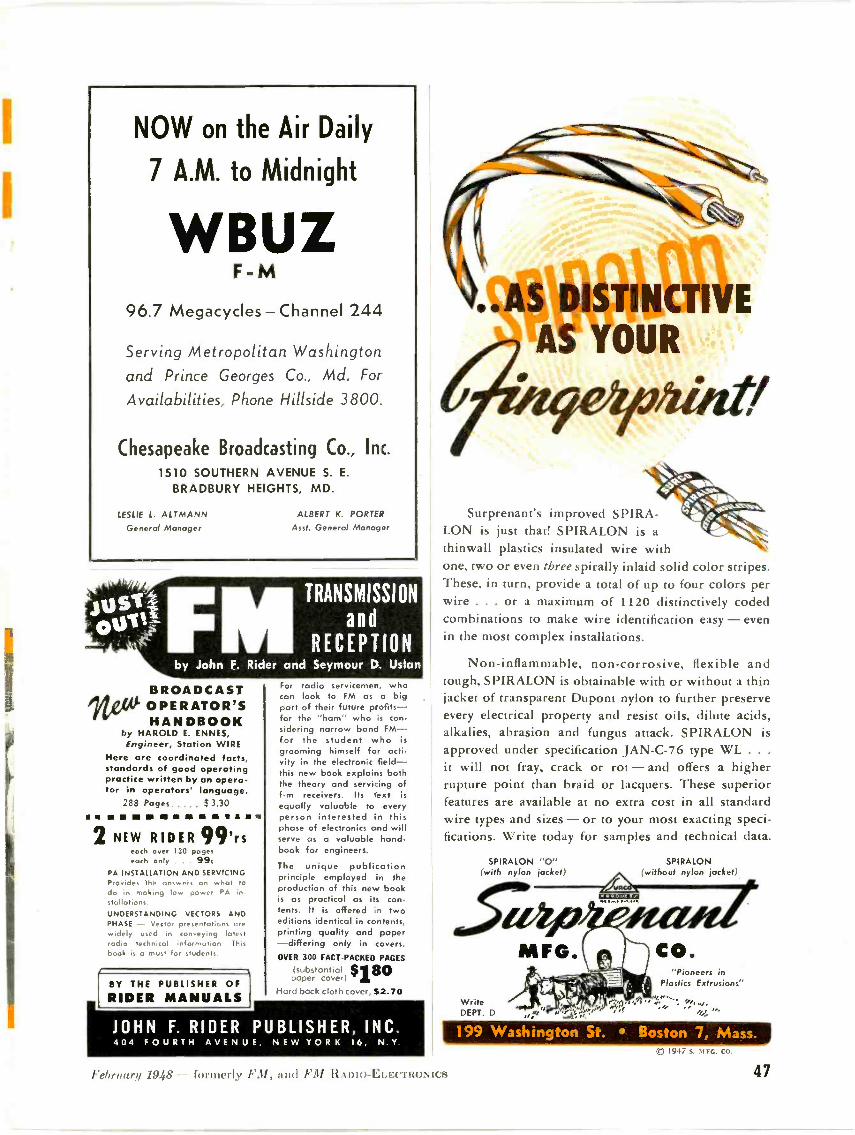
NOW on the Air Daily
7 A.M. to Midnight
WBUZF -M
96.7 Megacycles - Channel 244
Serving Metropolitan Washingtonand Prince Georges Co., Md. ForAvailabilities, Phone Hillside 3800.
Chesapeake Broadcasting Co., Inc.
1510 SOUTHERN AVENUE S. E.
BRADBURY HEIGHTS, MD.
LESLIE L. ALTMANNGeneral Manager
ALBERT K. PORTER
Aso. General Manager
BROADCAST/VW OPERATOR'S
HANDBOOKby HAROLD E. ENNES,Engineer, Station WIRE
Here are coordinated facts,standards of good operatingpractice written by an opera-tor in operators' language.
288 Pages $ 3.30
ellosimmanwayws.2 NEW RIDER 99'rs
each over 130 pageseach only . . 99c
PA INSTALLATION AND SERVICINGProvides the answers on what todo in making low power PA installations.UNDERSTANDING VECTORS ANDPHASE - Vector presentations arewidely used in conveying latestradio technical information Thisbook is a must for students.
BY THE PUBLISHER OFRIDER MANUALS
For radio servicemen, whocan look to FM as a bigpart of their future profits-for the "ham" who is con-sidering narrow band FM-for the student who isgrooming himself for acti-vity in the electronic field-this new book explains boththe theory and servicing off -m receivers. Its text isequally valuable to everyperson interested in thisphase of electronics and willserve as a valuable hand-book for engineers.
The unique publicationprinciple employed in theproduction of this new bookis as practical os its con-tents. It is offered in twoeditions identical in contents,printing quality and paper-differing only in covers.
OVER 300 FACT -PACKED PACES
(substantial 11$80paper cover)Hard back cloth ri $2.70
JOHN F. RIDER PUBLISHER, INC.404 FOURTH AVENUE, NEW YORK 16, N Y
Surprenant's improved S PIRA-LON is just that! SPIRALON is athinwall plastics insulated wire withone, two or even three spirally inlaid solid color stripes.These, in turn, provide a total of up to four colors perwire . . . or a maximum of 1120 distinctively codedcombinations to make wire identification easy - evenin the most complex installations.
Non -inflammable, non -corrosive, flexible andtough, SPIRALON is obtainable with or without a thinjacket of transparent Dupont nylon to further preserveevery electrical property and resist oils, dilute acids,alkalies, abrasion and fungus attack. SPIRALON isapproved under specification JAN -C-76 type WL . . .
it will not fray, crack or rot - and offers a higherrupture point than braid or lacquers. These superiorfeatures are available at no extra cost in all standardwire types and sizes - or to your most exacting speci-fications. Write today for samples and technical data.
SPIRALON "0" SPIRALON(with nylon jacket) (without nylon jacket)
WriteDE°T. D
MFG.f9114,\IP
1,
"Pioneers inPlastics Extrusions"
199 Washington St. Boston 7, Mass.(0 1947 g. UFn.. CO.
February 1948 - formerly 31, and FM ItAmo-ELErmoNics 47

The "Buy -Word" for"Sales -Time!"
WELD -FMOhio's First FM Station, COLUMBUS
When sponsors want their messages HEARD, they turn to thesymbol of Frequency Modulation in Central Ohio, WELD -FM. Timeon this station is "SALES -TIME" for there is never any static, fadingor other station interference . . . a powerful sales influence in
8,000 square miles of rich, result-ful market. Send NOW for yourrate card.
11e._ 1111Watts Radiated Power
Central Ohio's Bright Spot
FM LICENSE REQUIREMENTS
(CONTINUED FROM PAGE 46)
to emphasize that the EU engineeringstandards are not being changed, butonly that additional time is being pro-vided where necessary to meet thesestandards. This procedure will also per-mit more expeditious licensing of F\1stations.
With respect to the field intensity meas-urements required of Class B FM sta-tions by Section 3.216 (c) of the rules,the Commission has received inquiriesconcerning the time within which suchmeasurements must be submitted. As in-dicated by a footnote to the rule, thismaterial "shall he submitted within oneyear after the license has been issued orwithin such extension of time as the Com-mission may for good cause grant."
The Commission does not desire to im-pose an undue burden on FM licensees.However, the Commission wishes to ob-tain as much data as possible concerningFM service areas in order to provide forthe best allocation and use of the FMband. While the Commission expects tofollow a lenient policy concerning therequirement of field intensity measure-ments, it is hoped that FM licensees, par-ticularly of the larger stations, will en-deavor to supply this data as promptly asfeasible.
HARRY SADENWATER REPORTS:
"I just had to phone you about the soapoperas on FM. I've been listening to themall afternoon, and even they are wonder-ful on FM." That was Harry Sadenwaterreporting. Maybe you remember him as aradio operator on the first transatlanticflight of the NC planes in 1919.
Or perhaps you know him because hehas sold more radio broadcast stationequipment than most anyone else. At anyrate, Harry Sadenwater knows broadcastperformance and programs from listeningto them.
We were particularly impressed withhis enthusiasm over the network programson FM because he lives in the heart ofNew York City, and we have heard somany people say that reception is so
good in metropolitan areas that FMcouldn't be any better. Maybe a lot ofother people should take a tip fromHarry Sadenwater and spend an after-noon getting first hand information.
Of course, he did have some criticismsof AM studio techniques applied to FM.Specifically, "News reporters, speakers.and announcers would sound better onFM if they had a separate microphone. set back two or three feet. It's all right forthem to cuddle up to the AM mike, but itjust doesn't do on FM."
48 FM AND TELEVISION
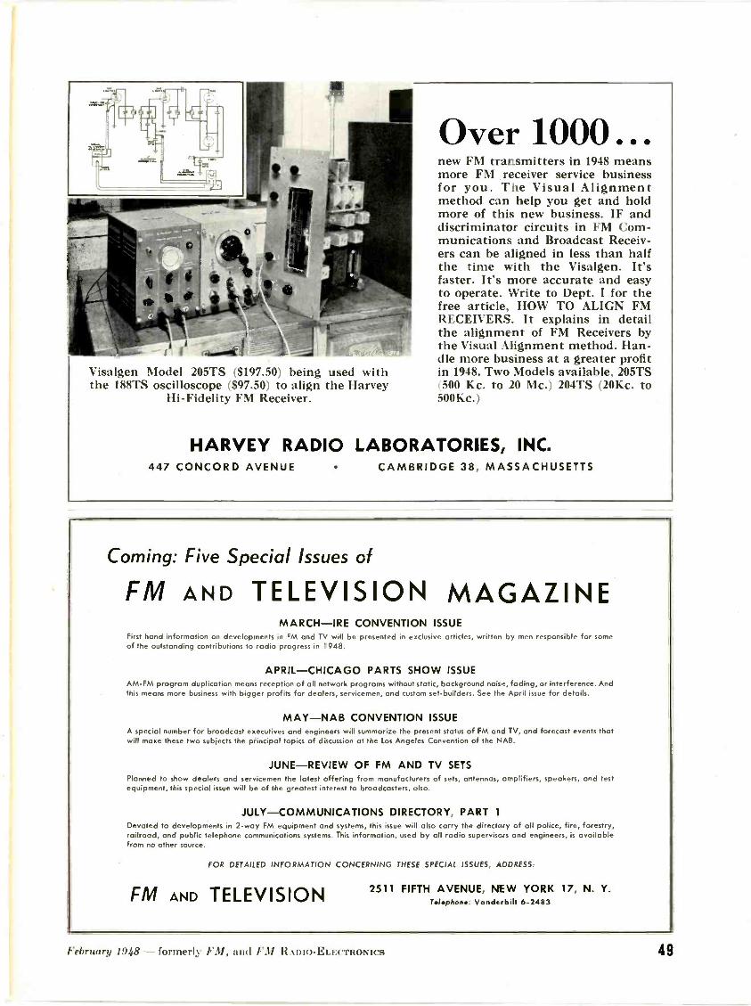
Visalgen Model 205TS ($197.50) being used withthe 188TS oscilloscope ($97.50) to align the Harvey
Hi -Fidelity FM Receiver.
Over 1000...new FM transmitters in 1948 meansmore FM receiver service businessfor you. The Visual Alignmentmethod can help you get and holdmore of this new business. IF anddiscriminator circuits in FM Com-munications and Broadcast Receiv-ers can be aligned in less than halfthe time with the Visalgen. It'sfaster. It's more accurate and easyto operate. Write to Dept. I for thefree article, HOW TO ALIGN FMRECEIVERS. It explains in detailthe alignment of FM Receivers bythe Visual Alignment method. Han-dle more business at a greater profitin 1948. Two Models available, 205TS(500 Kc. to 20 Mc.) 204TS (20Kc. to500Kc.)
HARVEY RADIO LABORATORIES, INC.447 CONCORD AVENUE CAMBRIDGE 38, MASSACHUSETTS
Coming: Five Special Issues of
FM AND TELEVISION MAGAZINEMARCH-IRE CONVENTION ISSUE
First hand information on developments in FM and TV will be presen.ed in exclusive articles, written by men responsible for someof the outstanding contributions to radio progress in 1948.
APRIL-CHICAGO PARTS SHOW ISSUEAM -FM program duplication means reception of all network programs without static, background noise, fading, or interference. Andthis means more business with bigger profits for dealers, servicemen, and custom set -builders. See the April issue for details.
MAY-NAB CONVENTION ISSUEA special number for broadcast executives and engineers will summarize the present status of FM and TV, and forecast events thatwill make these two subjects the principal topics of discussion at the Los Angeles Convention of the NAB.
JUNE-REVIEW OF FM AND TV SETSPlanned to show dealers and servicemen the latest offering from manufacturers of sets, antennas, amplifiers, speakers, and testequipment, this special issue will be of the greatest interest to broadcasters, also.
JULY-COMMUNICATIONS DIRECTORY, PART 1
Devoted to developments in 2 -way FM equipment and systems, this issue will also carry the directory of all police, fire, forestry,railroad, and public telephone communications systems. This information, used by all radio supervisors and engineers, is availablefrom no other source.
FOR DETAILED INFORMATION CONCERNING THESE SPECIAL ISSUES, ADDRESS:
FM AND TELEVISION 2511 FIFTH AVENUE, NEW YORK 17, N. Y.Telephone Vanderbilt 6-2483
February 1948 formerly FM, and FM RAmo-ELEcTRoNics 49

WASH FMWASH_ngton, D. C.
ORIGINATING STATION
FOR THE
Cont./Junta 71QtweilLFeaturing regular live -talent broadcasts by
U. S. AIR FORCE CONCERT ORCHESTRA THURS. 9-10 p.m.
U. S. ARMY BAND WED. 8-9 p.m.ROCHESTER CIVIC ORCHESTRA FRI. 8:30-9 p.m.GENE ZACHER'S DANCE ORCHESTRA FRI. 8-8:30 p.m.U. S. NAVY BAND MON. 8-9 p.m.HOTEL CARLTON CONGO -ROOM DANCE BAND TUES. 8:30-9 p.m.
On the air since 1945 with interim power
15000 watt installation nearing completion
EVERETT L. DILLARD, General Manager
WMRC-FMGREENVILLE, S. C.
Building the Largest FM Audience in theCarolinas, by Giving the Finest FM Service
With 48.6 kw. of effective radiation on 93.3 mc.,
WMRC-FM has taken the lead in providing fine programswith powerful signals over the western and centralCarolinas and east to Rocky Mount, Goldsboro, Fayette-ville, Myrtle Beach, and Charleston, and extending toBristol and Danville, Va., Knoxville and Johnson City,Tenn., and Atlanta and Athens, Ga. Daily schedule, noonto 9:00 p.m.
Textile Broadcasting Co.WMRC and WMRC-FM
MICROWAVE HANDBOOK
(CONTINUED FROM PAGE 42)
in a dielectric. The magnetic field alsovaries in such event. This differs froma steady DC conduction current whichgives rise to a non -varying magnetic field.The combination of varying electric fieldand varying magnetic field, called the elec-tromagnetic field, has a tendency to propa-gate in the dielectric instead of remaininglocalized in the vicinity of the conductor.It is this tendency to propagate, increasingwith increased frequency, that makesradio communication possible.
Thus, what at first seems like an im-possible situation, because of the highreactance of a wire conductor, is very ad-vantageously solved by use of the dis-placement rather than the conductiontechnique. This could only be possiblewith microwaves, since the equivalentcondenser gap would have prohibitive re-actance at lower radio frequencies.
2.4 Simulated Components * As explained inthe foregoing sections, microwaves involvethe use of AC frequencies much too highto permit lumped inductance or lumpedcapacitance. This becomes a problem evenbefore the microwave frequencies arereached. However, on HF or VHF, thewavelength is still appreciable comparedto physical dimensions involved, and con-ventional methods are still usable, eventhough the efficiency begins to fall off.
On microwaves, however, that problemis not only possible of solution, but thesolution represents an important advancein the radio art. The phenomena existingalong the length of a 2 -wire line or a wave -guide, between zero and one -quarter wave-length, make possible conditions thateliminate the need for coils, condensers,transformers, resistors or insulators. Manyor all of these components can be elimi-nated by taking advantage of the inver-sion, capacitive, inductive and transfor-mation effects existing along a quarter -wavelength of an overall half -wavelengthin a 2 -wire line or waveguide.
Figs. 6 and 7 show various effects orconditions existing along 2 -wire shortedor open lines, or a waveguide of suitabledimensions. AC energy can be introducedat one point and observed as indicatedat any other point. Typical effects orresults which can be developed along afractional wavelength of a transmissionline are:
1. Capacitive effects without a con-denser.
2. Inductive effects without coils orinductances.
3. A series -circuit effect without a con-denser in series with an inductance.
4. A parallel -circuit effect without aninductance shunted by a condenser.
5. A step-up transformer effect obtainedby introducing energy at a point of low
(CONCLUDED ON PAGE 51)
50 I'M AND TELEVISION

MICROWAVE HANDBOOK(CONTINUED FROM PAGE 50)
impedance and removing it at a point ofhigh impedance, with a resulting auto -transformer effect.
6. A step-down transformer effect ob-tained by suitable connection at a pointof low impedance.
7. An AC insulator effect obtained byconnecting to a point of high impedanceeven though it is a metallic connection.
8. Any value of impedance between vir-tually zero and infinity can be foundsomewhere along a quarter -wave section.It requires only a suitable connection orprobe at the correct point withinquarter -wave length.
9. Any condition can be inverted bymoving a quarter -wave away from an op-posite condition.
10. Any condition can be repeated bydouble -inversion. or moving a distance'oftwo quarter -waves from the point wherethe original condition exists.
Referring again to Figs. 6 and 7, thecircuit equivalents shown exist in either-a shorted or an open 2 -wire line. The samereasoning applies also if a waveguide is:substituted for the 2 -wire line. Eight con-ditions are spotted in the illustration. Itshould be understood that the conditionsdo not change abruptly or exist only atthose points. Between the points indi-cated there are intermediate effects. Bychanging the distances, the inductive,capacitive, or tuned -circuit effects vary.
Both the 2 -wire lines shown are 1 wave-length long. This is 39.37 ins. at 300 inc..about 4 ins. at 3,000 Inc., and only .4in. at 30.000 mc. A full set of changes canoccur in one-half that distance. There isno reason why the same techniques can-not be used on lower frequencies. exceptthat the physical dimensions become im-practicable. The line would have to be1,000 ft. long for a typical broadcast -hand frequency. The solid sine wave linein Figs. 6 and 7 is the voltage at variouspoints, while the dotted line representscurrent. Wherever the voltage is shownus minimum or the current is shown asmaximum, the impedance is minimum orvirtually zero. Wherever the voltage isshown as maximum or the current isshown as minimum. then the impedanceis maximum or virtually infinite. All theconditions are repeated every half -wavedown the line.
These can he summarized as correspond-ing to the following circuit equivalents:
CON-DITION SHORTED LINE OPEN LINEAZero°Zero A
45°nth
Minimum impedanceMinimum voltageMaximum currentVoltage & currentnearly equal
Impedance is an in-termediate valueCircuit behaves likea pure inductance
C Maximum impedance
Maximum impedanceMaximum voltageMinimum currentVoltage. current. &impedance same asfor shorted line, butopposite in phase
Circuit behaves likepure capacitanceMinimum impedance
HIGH
GAIN
on 13
Channels
COLLINS ALL -CHANNELTelevision Antenna Assures:
1. Sharp, Steady Images:Stronger signals give better re-ceptior on any set. The high gainof the COLLINS all -channel an-tenna means peak performancethat keeps customers happy.
2. Static Protection: Whenimages tear and lose sync be-cause of static interference, theonly answer is to feed strongersignals to the receiver. A COLLINSantenna is the solution whereverthere is static trouble.
3. All -Channel Reception:The multiple construction of theCOLLINS antenna gives maximumefficiency on all 13 televisionchannels, plus the FM band. Ordi-nary antennas can pick up only3 or 4 channels.
4. Low Cost: One COLLINSantenna does the work of 3 ordi-nary types, cut to different sizes.
Thus it costs less, and eliminateschanging antennas when the re-ceiver is switched from one partof the band to another.
5. No Interference: With newstatiors coming on the air, theres already interference in somesections from receiving two sta-tions on the same channel. ACOLLINS antenna, properly in-stalled and adjusted, will preventsuch interference.
6. Ease of Installation: Thelight weight and low wind resist-ance of a COLLINS antenna sim-plifies installation. Use any typeof lead, from 73 to 300 ohms,according to receiver specifica-tions.
7. Dealers, Jobbers, Manu-facturers: write for technicalinformation, prices, and deliveries.
Licensed under Amy, Aceves & King patents issued and pending
COLLINS MACHINE CO.56-22 Northern Blvd., Woodside, New York
90° NIaximuin voltageji A Minimum current
Circuit behaves likea parallel -resonantcircuit
D Same as B for open135° linefin,E Same as C for open180° line54AF Same as B for shorted225° linet.thG Same as C for shorted270° line54thH Same as D for shorted315° line%titI Same as E for shorted360° lineI ).
Minimum voltageMinimum currentCircuit behaves likea series resonant cir-cuitSame as B for shortedline
Same as C for shortedline
Same as B for openline
Same as C for openline
Same as D for openline
Same as E for openline
If the "2 -wire line or waveguide is 11.i
wavelengths for example, conditions willhe the same as at the ,1/4. wavelengthposition. The same would occur at '214,3%, etc.
The line ran lie used as a wavemeter orequivalent frequency meter by measuringthe distance between any two adjacentidentical conditions. For example. the dis-tance between two maxima or two minimawith respect to either current, voltage, orimpedance corresponds to a half -wave-length.
To be continued next month
February 1948 - formerly FM, and F.11 RADIO -ELECTRONICS 51

wghf101.9 MC.
THE FINCH FM -FACSIMILE STATION
Presenting more and more live -talent
shows for listeners within 70 miles of
New York City. Now operating on20 kw effective power. Hours of
operation: 3:00 to 12:00 m.
FREQUENCY 101.9 MC.
Studios and Transmitter: 10 E. 40th St., New York City
Telephone Lexington 2-4927
in the great
wFAA_Fm.(formerly
First FM stationBillion DollarWorth - operatingwith 14,000
97.9 Mc. WFAA-FMA RADIO SERVICE
Dallas,
NewSouthwescl!
KERA)
in the Southwest'sMarket -
ninewatts radiated
OF THE DALLAS
Texas
ERA
DallasBiggest
and Forthours daily
power.
Channel 250MORNING NEWS
16 -IN. PICTURE TUBEProduction of a 16 -in. television tube is
getting under way at RCA's Lancasterplant. It will provide an intermediate sizebetween the 10- and 14 -in. direct -viewing tubes, and projection receivers.
Unlike the smaller sizes, the new tubewill have a metal cone, with a glass face-plate and neck. This type of constructionhas been made possible by the perfectionof techniques for sealing large areas ofmetal to glass. A picture area of 125square inches is obtainable on the 16 -in.face. The new tube is now being demon-strated at Lancaster.
SERVICEMEN HAVE A NEW LOOK(CONTINUED FROM PAGE 23)
fidelity FNI network programs, such asthose put on by Continental. The service-man who takes upon himself the responsi-bility for supplying this information willaid the salesmen tremendously.
It all boils down to the fact that therearen't enough able servicemen to takecare of the FM and TV sets that are beingsold. As a result, a great many aren'tworking properly. No one knows theactual number, but it's suddenly comingto light that it is large enough to hurtsales in 1948 unless the situation is cor-rected quickly. There are more FM re-ceivers in this category than TV sets,partly because many more FM receivershave been sold, and partly because theprincipal TV manufacturers have set up in-stallation and maintenance organizations.
Whatever the total, it is so large as tocreate a demand for competent service-men far beyond the supply, to the pointwhere dealers will soon be hiring the goodones away from each other this year.
With all the network programs avail-able from hundreds of FM stations, andmore television broadcasting in moreareas, it isn't going to be any problem to.sell sets. However, the time when cus-tomers could be bluffed into acceptingless than perfect performance is past.That's why the dealers who have com-petent servicemen are going to get thebulk of the business in 1948.
NEWS PICTURES(CONTINUED FROM PAGE 27)
ware, is producing H- and 14 -in. reflec-tors of the same material for televisionprojectors. Preformed blanks are grounddown about .04 in., and polished. Thenthe concave surface is coated with alu-minum by the high -vacuum evaporationprocess. The reflectors are produced bythe McKee Glass Company, Jeanette, Pa.
C Physicists at Bell Laboratories areworking with a new tube in which
amplification up to 500 times has beenobtained shooting a stream of electrons ata diamond chip. Such tubes may be ofgreat aid in the study of the fundamentalstructure of solid matter, and its behaviorunder the impact of electrons.
52 FM AND TELEVISION

FM -AM DUPLICATION PACT' FM -AM duplication was specified bythe net works-AFM agreement in theseterms: -Recognizing the desirability ofbroadening the public opportunity tohear more music on FM broadcasts andin the expectation that FM broadcastswill provide additional employment op-portunities for musicians, the parties arehappy to announce that, in the meantime.(while final contract terms are beingworked out) FM duplication of AM pro-grams will begin on February 1. 1948.-
UNIVERSAL FM RECEIVER(CONTINUED FROM PAGE 22)
lator, or an FM station near the top ofthe band.
I. Connect the signal source to thetwo antenna terminals. Disconnect theground link. If a signal generator is used,make the connection through a 300 -ohmdummy load.
2. Plug in the line cord.3. Turn on the monitor switch.4. Set the volume control at 5.
- 5. Set the tone control at 10.6. Set the dial pointer at the exact
frequency of the test signal.7. Adjust C5 to receive the test signal.8. Adjust CI and C9 for maximum
gain as indicated by the tuning indicator.9. Recheck step 7. and repeat steps
7 and 8 to obtain maximum reading onthe tuning indicator. This completes thealignment steps.
FM PROPAGATION TESTS(CONTINUED FROM PAGE 36)
inconsistent with the other figures shownin the charts for the low band signals.
The discrepancy between Fig. 4 andFig. I with respect to the high band iseven greater, and it also involves a mathe-matical absurdity. There the comparativefigures for signal drops below 5 microvoltsis 4% of the time for 5 months and .41:;of the time for 7 months.
4% of the time in .5 months is 44.51;;of 1 month of testing time. If 4 additionalmonths be added - even if no drops below5 microvolts had occurred in those 4months - the total amount of such dropsduring the whole period would still behe 24.5% of a month. Mr. Allen, however.adds the 2 months and comes out with afigure of two -tenths of I% for the drop-outs during the whole 7 months, i.e.,1.4c;of a month. The report gives no clue as tohow this mathematical miracle was per-formed, but the effect was to lose 41.1(7, ofa month of poor signals.
After I completed my analysis. I
pointed out this error to Mr. Allen, whorecognized it at once but was unable toexplain it. After conferring with hisassociates. who apparently had plottedthe curves, he furnished me with the
(CONCLUDED ON PAGE 54)
WIDE RANGE
0111.0M.W1111.1.111.
DISPLAYS PASS BANDContinuous frequency coverage up through thecolor television bands.
IN GOOD COMPANY4,0
federal Teecommunicallow taborulorics.loc
RA/0°1"LA"LEPH"E
TE
GENIIIAlELECTRIC
COMPANY
ads
eAfTBIlle
BE LIIA0111 RADIO CORPORATION
'11-1 E m E (7,2'A. swErpA VALUABLE INSTRUMENT FOR SERVICING FM & TELEVISIONCARRIER FREQUENCY50 kilocycles to 500 megacycles and up.FREQUENCY SWEEPFrom 30 megacycles to 33 kilocycles, throughout the complete spectrum.
CONTINUOUSLY VARIABLE ATTENUATORLOW AMPLITUDE MODULATION WHILE SWEEPINGLess than 0.1 DB per megacycle.
PRECISION WA VEMETERSelf-contained, Regulated, Power Supply -117 Volt 60 Cycle operaticn-Size9" x 17" x 11"-Weight 35 Pounds.Price S395 F.O.B. Newark, New Jersey.
Mfrs. of The MICRO-PULSER, The TOLCH-TIMER, Micro -Wave components andHigh -Frequency Wavemeters, and other specialized electronic instruments.
Lnat'LLIMIT (CDDEPT. F, PINE BROOK. NEW JERSEY
February 1948 - formerly FM, and FM RAimo-ELEcritoNtcs 53

InvestigateA lden Facsimile
FM Stations use the Alden Facsimile systemas a promotional means to increase theirlistening audience and call attention totheir FM stations.
Thev choose Alden because:
I. The Alden Recorders produce the mostbeautiful pictures not only in black and whitebut in the pleasantly toned Alfax sepia papers.
2. The Alden system assures attention -gettingprograms by combining sound and the opera-tion of bulletin -size recorders in semi-publicplaces, enlarging the same program that is sentto the home and other points.
3. The Alden system with its low frequency re-quirements simplifies the operation over ordi-nary telephone lines and with existing com-munication sets, making it capable of universaladoption.
4. The Alden system is designed and pricedfor the mass market; is not restricted as toparticular FM sets and thus has the promo-tional interest of all set dealers in your area.5. The Alden equipment has basic simplicity,minimizes service through interchangeablespare parts and is thoroughly suitable for useby non -technical people.
6. The Alden system has every factor, in-cluding program possibilities, that insure thelargest saturation of recorders per area, opera-tion in marginal signal areas, and thus thegreatest possible coverage for your station.
Inrestigaie Alden Facsimileand Alfax Paper now
ALDEN PRODUCTS CO.Brockton 64F. Massachusetts
COME!
to theI.R.E.
National ConventionAND
Radio Engineering ShowMARCH 22-25, 1948
Grand Central Palace, New York CityHEAR -over 100 Technical papers,
many on F.M. and television.MEET -many old friends.SEE -167 Engineering Exhibits.
4 Day Registration is $3.00
ATHE INSTITUTE OFRADIO ENGINEERS, INC.
1 East 79th StreetNew York 21, N Y
FM PROPAGATION TESTS(CONTINUED FROM PAGE 53)
Errata sheet mentioned above. Oile ofthe corrections therein was a change ofthe .2% figure to 2.7%.
That 1250% correction, however, didnot remove the mathematical absurdity,since 4% of 5 months is still 22.5% of amonth, and 2.7% of 7 months is only18.9% of a month. Mr. Allen has stilllost 3.6% of a month even assumingthat there were no drop -outs in theadditional 2 months - an assumptionwhich a glance at the recordings will showto be unjustified.
There are other errors in the charts, butit seems hardly necessary to go further toshow the unreliability of Allen's methodsand conclusions. The apparatus at West-hampton Beach is available for inspectionand use by the members of the Commis-sion or any of its staff at any time, and forwhatever period of time may be considerednecessary. 7 Similar apparatus, which hasbeen used to make similar tests at Mt.Holly, N. J., 77 miles from the Alpinetransmitter, can also be made availablefor the inspection and use of the Com-mission or its staff, either at Mt. Hollyor at Southampton, Pa., or at any otherplace where the Commission may desireto witness tests.8
The Westhampton Beach recordings area conclusive demonstration of the effectsof fading on the upper band and therelative absence of that phenomenon onthe lower band. No attempt was made atthe hearing to dispute the Westhamptonrecordings or to deny what they showed.Allen expressly admitted on the standthat those recordings showed exactlywhat I said they showed (Tr. 736).
Norton's Testimony * As I have pointed outhefore, the Commission has had badengineering advice from its staff on therelative efficiency of the low and the highFM hands since the presentation of theNorton testimony at the 1944 hearing:At that time Mr. Norton made a basicerror which not only misled the Com-mission but which was also kept out of thepublic record for over 3 years. That errorhas now been admitted by Norton at thepresent hearing (Tr. 782-84).
Mr. Norton has now attempted toshift to the Commission the responsibilityfor overlooking what tropospheric fadingwould do to the service range on the highhand, by contending that he informed theCommission about such fading in anearlier hearing (Tr. 776). But what hefails to point out is that all that testimonywas given 7 months after the final decision
7 The Westhampton Beach recordings were repro-duced for only 2 months, because of the expense ofreproduction, but the recordings for the period sinceSeptember 6 are available for the Commission's in-spection, if desired.
Tests were made at Mt. Holly during the hearingsand showed results similar to those arrived at in theWesthampton tests.
to put FM "upstairs." and only after thetests at Deerfield had made it.
impossible to ignore the fading phenome-non. Norton also refers to two exhibitswhich he introduced at the October, 1944.hearing, but only one of them is pertinent(Ex. 433), and that contains merely aone -sentence statement, on page 4. that:"Fading may he expected to be somewhatmore severe as the radio frequency isincreased through the range from 50 to300 mc. and at the shorter distances forthe higher frequencies."
No reference was made to that vaguepronouncement at any time (luringNorton's testimony. On the contrary, atthe same hearing Norton made the flatstatement that:
"Fortunately, from the propagationstandpoint. this [the shift to the upperhand] does not involve a compromise. Forthe same power input into the transmit-ting antenna I would expect slightly largerFM service areas on frequencies between130 and 200 mc. than on 45 inc. even if allof the listeners use receiving antennaswhich are built into their receivers."
My statement to the Commission atthe hearing in the present proceeding, con-cerning the way Mr. Norton had pre-sented his ground wave calculations to theCommission, will he found to be fullyborne out by reference to the Nortontestimony at those hearings (Docket No.6651, Tr. 3772: Docket No. 8487, Tr.776).
The transfer of FM broadcasting fromthe lower to the higher frequency rangewas set in motion by the dramatic ap-pearance of Mr. Norton at the 1944hearings with the prediction. based uponalleged secret data in possession of theArmed Forces, that ionospheric disturb-ances caused by sun spots would seriouslyimpair service on frequencies up to 80 mc.,and possibly even to 120 mc.
On this subject Mr. Norton was askedby me on cross-examination (Tr. 784):
"But you were wrong?"and he replied (id):
"Oh, certainly, I think that can happenfrequently to people who make predictionson the basis of partial information. It hap-pens every day."
No one will dispute that statement.
Condusion * In my original brief in stillsproceeding I urged the Commission tomake a correct ascertainment of thescientific facts before rendering its de-cision. If, now, there be any doubt in theminds of the Commission as to the con-clusiveness of the Westhampton Beachrecordings as proof of the effects of thefading phenomenon in the 50-mc. and100-mc. areas, then it is urged that thehearings be reopened so that the unre-liability of the Allen tests and charts mayhe more fully explained to the Commis-sion.
Respectfully submitted,EDWIN H. ARMSTRONG
54 FM AND TELEVISION

ADVERTISERS INDEXAdair, George P. 17Alden Products Company 54Altec Lansing Corp. 4Amy, Aceves & King, Inc ... 17Anderson & Merryman 17Andrew Corporation 6 16
Barone, S. A., Company 17Bell Telephone Labs 5 18Blaw-Knox Company 12Boonton Radio Corp. 55Browning Laboratories, Inc 2
Capitol Transcriptions 7Chesapeake Bcstg. Co. 47Clare, C. P., & Company 10, 11Collins Machine Co. 51Collins Radio Co.. . . Inside Back CoverCommercial Radio Equip. Co. 17
Davis, George C. 17DeMars, Paul A. 16
Eitel-McCullough, Inc.
Federal Telephone & Radio Corp.... 13FM Company 45, 49
General Radio CompanyGraybar Electric Co.
1 70 -A
METER
A ruggedly constructed direct reading laboratory instrument56 specially designed to measure Q, inductance, and capacitance
values quickly and accurately. Invaluable in selecting proper lowloss components for high frequency applications.
SPECIFICATIONS:-FREQUENCY RANGE: 20-200 mc, accuracy 1%1 RANGE OF Q MEASUREMENT: 80 to 1200
18 Q CAPACITOR RANGE: 11-60 mmf; accuracy or 0.5 mmf, whichever is greater
Harvey Radio Labs, Inc. 49Hewlett-Packard Co. 14. 15
Inst. of Radio Engineers, Inc. 54
James Knights Company, The 55Jansky & Bailey 16
Karp Metal Products Co., Inc. 43Kay Electric Company 53Kear and Kennedy 17
Leftwich, William 55
Maguire Industries, Inc. 44Mallory & Co., Inc., P. R. 9May, Russell P. 16McCachren, Winfield Scott 17McIntosh, Frank H. 17McKey, Dixie B. & Assoc 16McNary and Wrathall 17
Pollack, Dale 16
Radio Consultants, Inc. . 17Radio Corp. of America 28, 29Radio Engineering Labs. Inc. Back CoverRadio Music Corp.Ray, Garo W. 16Raytheon Mfg. Co...Inside Front CoverRCA Communications, Inc. 16Rider, John F. 47
Smeby, Lynne C.. 16Surprenant Electric Co 47
U. S. Recording Co. 17
Ward Products Company 41WASH -FM 50WBEN-FM 48WCFC 46WELD 48Western Electric Co. 18WFAA-FM 52WGHF 52Williams, Nathan 16Wilmotte, Raymond M. 16WMRC-FM 50Workshop Associates, The 16
IWRITE FORCATALOG "O"
1( BOONTON11-.1.1.1.S.A.
BOONTO RADIO 4110'
Ota/ii)/(DESIGNERS AND MANUFACTURERS OF THE "0" METER
GENERATOR..BEAT FREQUENCY GENERATOR.
WILLIAMLEFTWICH
Specialist inphotographing radio sets
and equipment
Many of the illustrationsyou have admired in FMand TELEVISION weremade from photographs byWilliam Leftwich.
They are distinguished bytheir sharpness, contrast,effective lighting, and verti-cal :ines that are parallelnot distorted.
Leftwich photographs costless because they seldomneed retouching, whethertaken on location or in thestudio.
William LeftwichPhone: Bryant 9-9790
2 West 45th St., New York City
OX CHECKER FREQUENCY MODULATED SIGNALAND OTHER DIRECT READING TEST INSTRUMENTS
JK STABILIZED HEAT JKO-7Designed to accommodate crystals from 80to 3,000 kc and recommended for broadcastand frequency standard applications. Operat-ing temperature 50° C plus or minusothers also on special order. Available asdouble oven on special order. Crystals electro-statically shielded. Better thermal insulationresults in lower heater current consumptionand shorter warm-up time. Also availablewith oven control.
VISIT JAMES KNIGHTS EXHIBITBOOTH H, IRE SHOW
GRAND CENTRAL PALACE.
The JAMES KNIGHTS CO.SANDWICH, ILLINOIS
February 194S - formerly FM, and FM RADIO-ELEcTRoxics 55
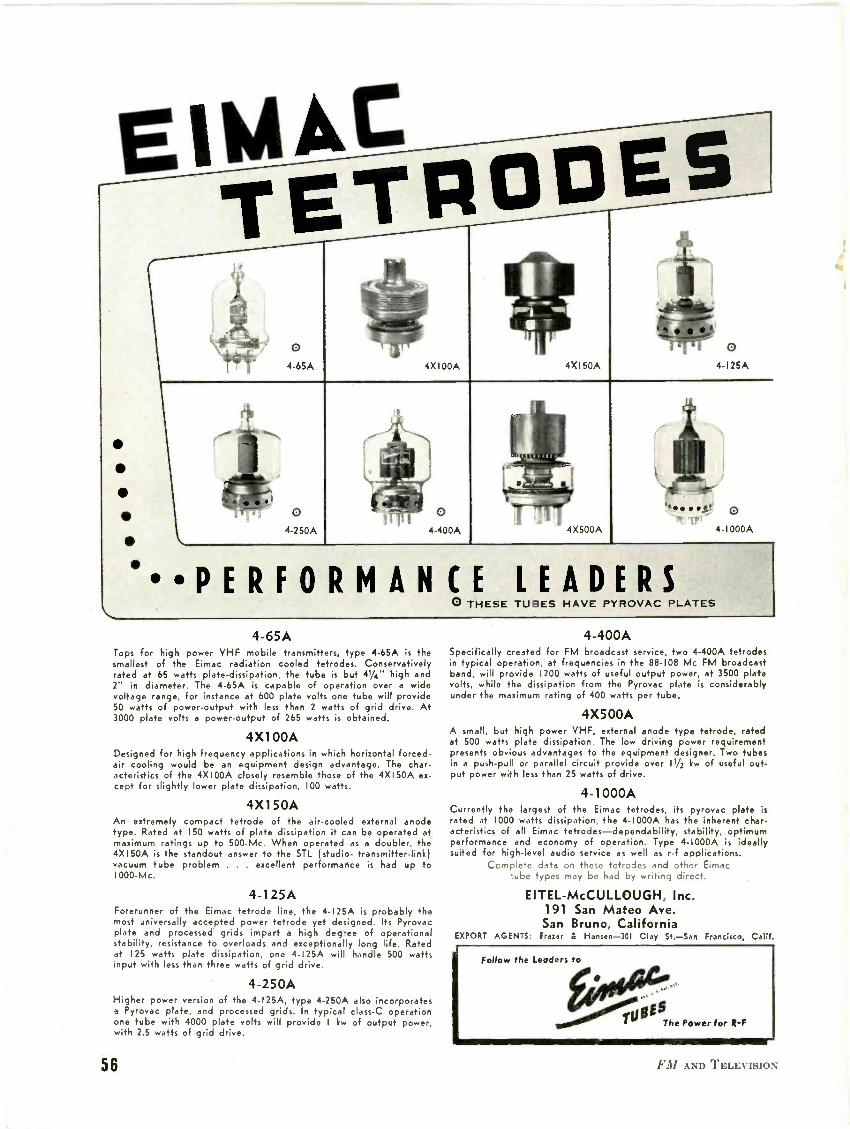
EIWIACTETR
04-65A
04-250A
4X100A
04-400A
4X150A
04-1000A
PERFORMANCE LEADERSTUBES HAVE PYROVAC PLATES
4-65ATops for high power VHF mobile transmitters, type 4-65A is thesmallest of the Eimac radiation cooled tetrodes. Conservativelyrated at 65 watts plate -dissipation, the tube is but 41/4" high and2" in diameter. The 4-65A is capable of operation over a widevoltage range, for instance at 600 plate volts one tube will provide50 watts of power -output with less than 2 watts of grid drive. At3000 plate volts a power -output of 265 watts is obtained.
4X100ADesigned for high frequency applications in which horizontal forced -air cooling would be an equipment design advantage. The char-acteristics of the 4X100A closely resemble those of the 4X150A ex-cept for slightly lower plate dissipation, 100 watts.
4X150AAn extremely compact tetrode of the air-cooled external anodetype. Rated at 150 watts of plate dissipation it can be operated atmaximum ratings up to 500 -Mc. When operated as a doubler, the4X150A is the standout answer to the STL (studio- transmitter -link)vacuum tube problem . . . excellent performance is had up to1000 -Mc.
4-125AForerunner of the Eimac tetrode line, the 4-I25A is probably themost universally accepted power tetrode yet designed. Its Pyrovacplate and processed grids impart a high degree of operationalstability, resistance to overloads and exceptionally long life. Ratedat 125 watts plate dissipation, one 4-I25A will handle 500 wattsinput with less than three watts of grid drive.
4-250AHigher power version of the 4-I25A, type 4-250A also incorporatesa Pyrovac plate, and processed grids. In typical class -C operationone tube with 4000 plate volts will provide I kw of output power,with 2.5 watts of grid drive.
4-400ASpecifically created for FM broadcast service, two 4-400A tetrodesin typical operation, at frequencies in the 88-108 Mc FM broadcastband, will provide 1200 watts of useful output power, at 3500 platevolts, while the dissipation from the Pyrovac plate is considerablyunder the maximum rating of 400 watts per tube.
4X500AA small, but high power VHF, external anode type tetrode, ratedat 500 watts plate dissipation. The low driving power requirementpresents obvious advantages to the equipment designer. Two tubesin a push-pull or parallel circuit provide over 11/2 kw of useful out-put power with less than 25 watts of drive.
4-1000ACurrently the largest of the Eimac tetrodes, its pyrovac plate israted at 1000 watts dissipation, the 4-1000A has the inherent char-acteristics of all Eimac tetrodes-dependability, stability, optimumperformance and economy of operation. Type 4-1000A is ideallysuited for high-level audio service as well as r -f applications.
Complete data on these tetrodes and other Eimactube types may be had by writing direct.
EITEL-McCULLOUGH, Inc.191 San Mateo Ave.San Bruno, California
EXPORT AGENTS: Frazer & Hansen -301 Clay St.-San Francisco, Calif.
56 1:31 AND TELEVIS.1117%;

A view of the Collins audio equipment andaccessories in KCRG-KCRK's speech rods
The master control console designed andconstructed by Collins for KCRG-KCRK
which is completely equipped
It is noteworthy that when the Cedar RapidsGazette decided to build the finest AM -FM
station that modern engineering could
produce, it chose advice and its entire
equipment from Collins-thus exploding
the idea that a prophet is not withouthonor save in his own community.
We of the Collins Radio Company are proud
to have contributed to the making of thisgrand new dual -service station, right
here in our own home town.
The Gazette's action, in awarding the contract
for all equipment to us, is characteristic ofa trend. A number of broadcasters have
done the same, preferring to rest allresponsibility in one dependable source.
Whether you plan to build a complete new
station or modernize your present station, we
urge you to consult our nearest office. We are
prepared to suplYy any or all equipment,
from studio to antenna, in AM and FM.
FOR BROADCAST QUALITY, IT'S ...
COLLINS RADIO COMPANY, Cedar Rapids, Iowa11 West 42nd Street, New York 18, N. Y. 458 South Spring Street, Los Angeles 13, California
RUMFORD PRESSCONCORD. N.
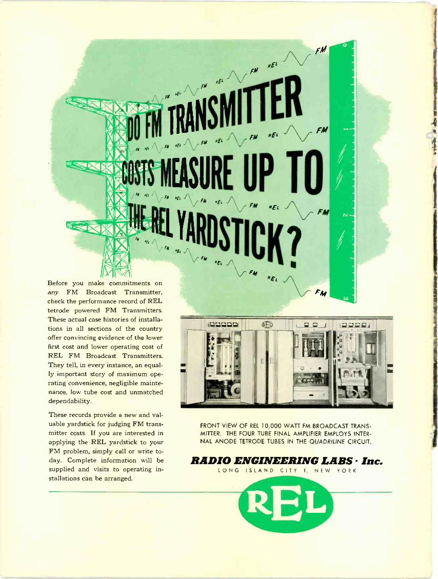
fli "E`
iM
r Pli
Before you make commitments onany FM Broadcast Transmitter,check the performance record of RELtetrode powered FM Transmitters.These actual case histories of installa-tions in all sections of the countryoffer convincing evidence of the lowerfirst cost and lower operating cost ofREL FM Broadcast Transmitters.They tell, in every instance, an equal-ly important story of maximum ope-rating convenience, negligible mainte-nance, low tube cost and unmatcheddependability.
These records provide a new and val-uable yardstick for judging FM trans-mitter costs. If you are interested inapplying the REL yardstick to yourFM problem, simply call or write to-day. Complete information will besupplied and visits to operating in-stallations can be arranged.
iTRArsirms,,m,
REl VRE,
EASURE UP TOEL 1\/ FM REL \./
'IRDSTICK?"Et
FMft EL A
\z,
FRONT VIEW OF REL 10,000 WATT FM BROADCAST TRANS-MITTER. THE FOUR TUBE FINAL AMPLIFIER EMPLOYS INTER-NAL ANODE TETRODE TUBES IN THE QUADRILINE CIRCUIT.
RADIO ENGINEERING LABS Inc.LONG ISLAND CITY 1, NEW YORK