87413621 pneumatics circuit
DESCRIPTION
pneumatic circuitTRANSCRIPT
A J AY C H A C K O
P R 11 M E 1 0 0 2
PNEUMATIC CIRCUITS
PNEUMATICS
Pneumatics system uses pressurised air to transmit
and control power. (or) Pneumatics is a type of
power transmission that uses a gas and pressure
differential to create movement.
Commonly Air is used as fluid which is freely and
safely available.
COMPONENTS OF A PNEUMATIC
SYSTEM
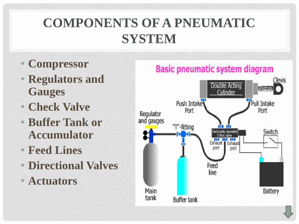
• Compressor
• Regulators and Gauges
• Check Valve
• Buffer Tank or Accumulator
• Feed Lines
• Directional Valves
• Actuators
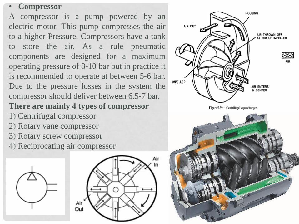
• Compressor
A compressor is a pump powered by an
electric motor. This pump compresses the air
to a higher Pressure. Compressors have a tank
to store the air. As a rule pneumatic
components are designed for a maximum
operating pressure of 8-10 bar but in practice it
is recommended to operate at between 5-6 bar.
Due to the pressure losses in the system the
compressor should deliver between 6.5-7 bar.
There are mainly 4 types of compressor
1) Centrifugal compressor
2) Rotary vane compressor
3) Rotary screw compressor
4) Reciprocating air compressor
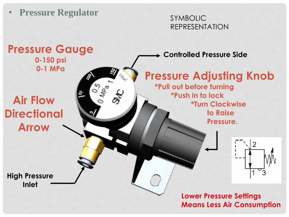
• Pressure Regulator
Pressure Adjusting Knob *Pull out before turning
*Push in to lock
*Turn Clockwise
to Raise
Pressure.
Pressure Gauge 0-150 psi
0-1 MPa
Air Flow
Directional
Arrow
Lower Pressure Settings
Means Less Air Consumption
High Pressure
Inlet
Controlled Pressure Side
SYMBOLIC
REPRESENTATION
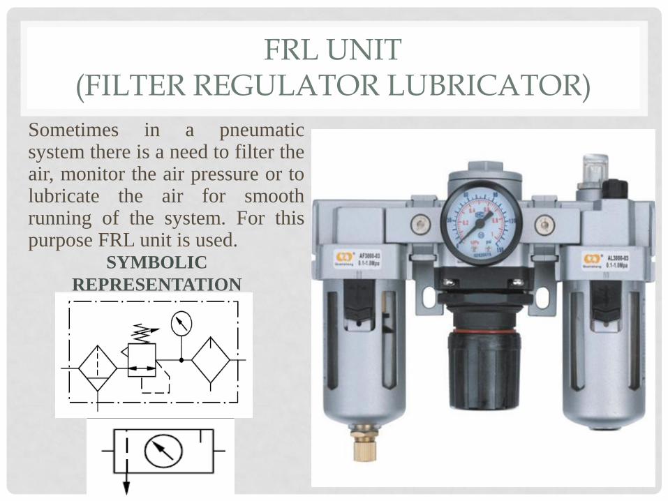
FRL UNIT (FILTER REGULATOR LUBRICATOR)
Sometimes in a pneumatic system there is a need to filter the air, monitor the air pressure or to lubricate the air for smooth running of the system. For this purpose FRL unit is used.
SYMBOLIC
REPRESENTATION
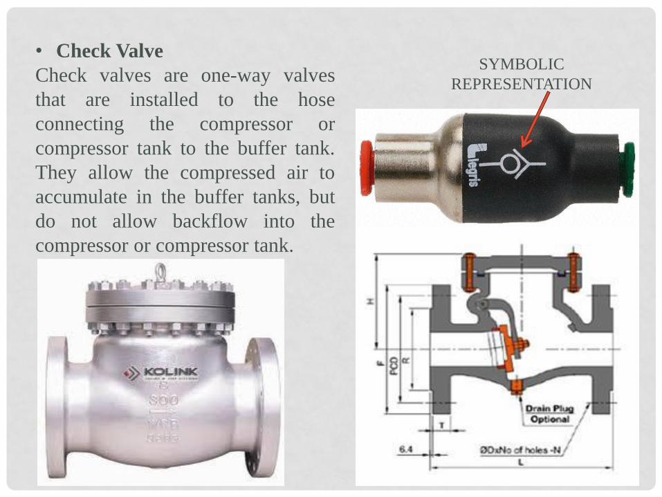
• Check Valve
Check valves are one-way valves
that are installed to the hose
connecting the compressor or
compressor tank to the buffer tank.
They allow the compressed air to
accumulate in the buffer tanks, but
do not allow backflow into the
compressor or compressor tank.
SYMBOLIC
REPRESENTATION
• Buffer Tank or Accumulator
Buffer tanks are secondary storage units for the compressed air originating
from the compressor. They store the high-Pressure compressed air for
eventual use with the pneumatic actuators. These tanks help to prevent
uneven airflow surges in the actuators; allow the compressor cycle to
maximize its shutoff timing; and allow the compressor to be kept at far
place from the actuators.
• Feed Lines
Feed lines are hoses that transfer pressurized air through the pneumatic
system. Large diameter hoses allow the pressurized air to travel quickly,
eliminating airflow backups.
The pipe diameter of the air distribution system should be selected in such a
way that the pressure loss from the pressurised reservoir to the consuming
device ideally does not exceed approx. 10 kPa (0.1 bar).
The selection of the pipe diameter is governed by:
1. Flow rate
2. Line length
3. Permissible pressure loss
4. Operating pressure
5. Number of flow control points in the line

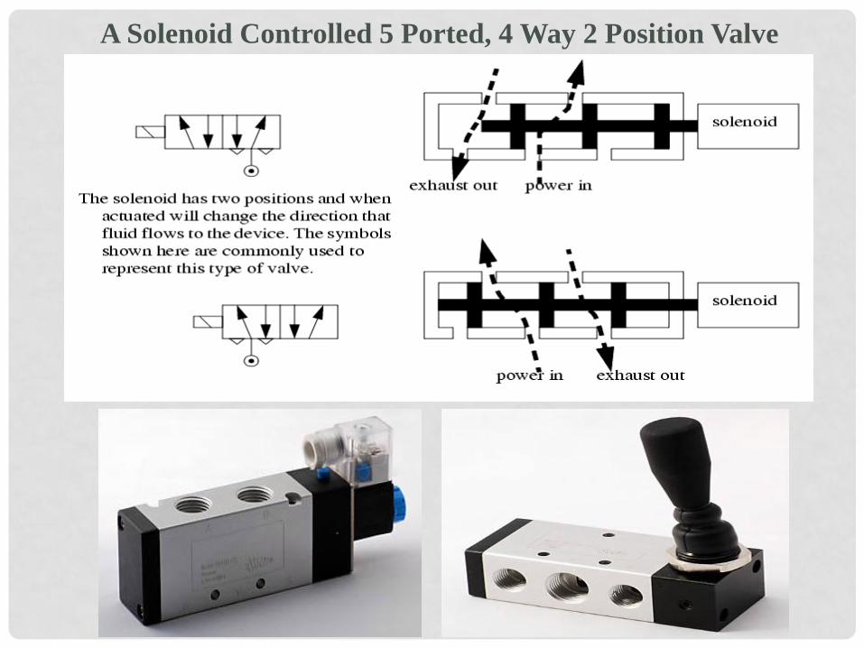
• Directional Valves
Directional valves are placed before actuators. Multiple-valve
systems are installed on projects with multiple actuators to power.
Directional valves receive input from mechanical or electrical
control sources. They re-direct, stop or release the pressurized air to
its appropriate actuators at the times desired. Directional valves can
be triggered by the action of a button, spring, lever, pedal, solenoid
or other device. The different types of DVC are spool type, poppet
type, seat type etc.
Spool Valve:
A spool moves horizontally
with in the valve body to
control the flow of fluid.
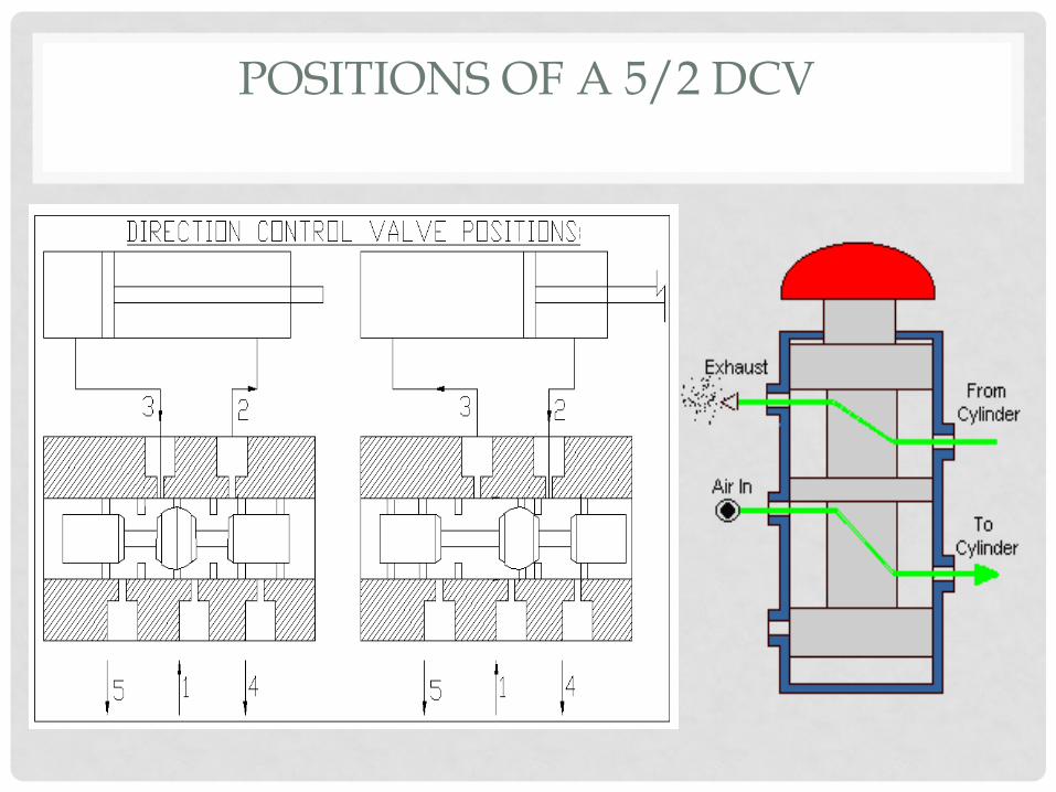
POSITIONS OF A 5/2 DCV

WORKING OF A SINGLE ACTING AND DOUBLE ACTING CYLINDER USING DCV
SINGLE ACTING CYLINDER
DOUBLE ACTING CYLINDER
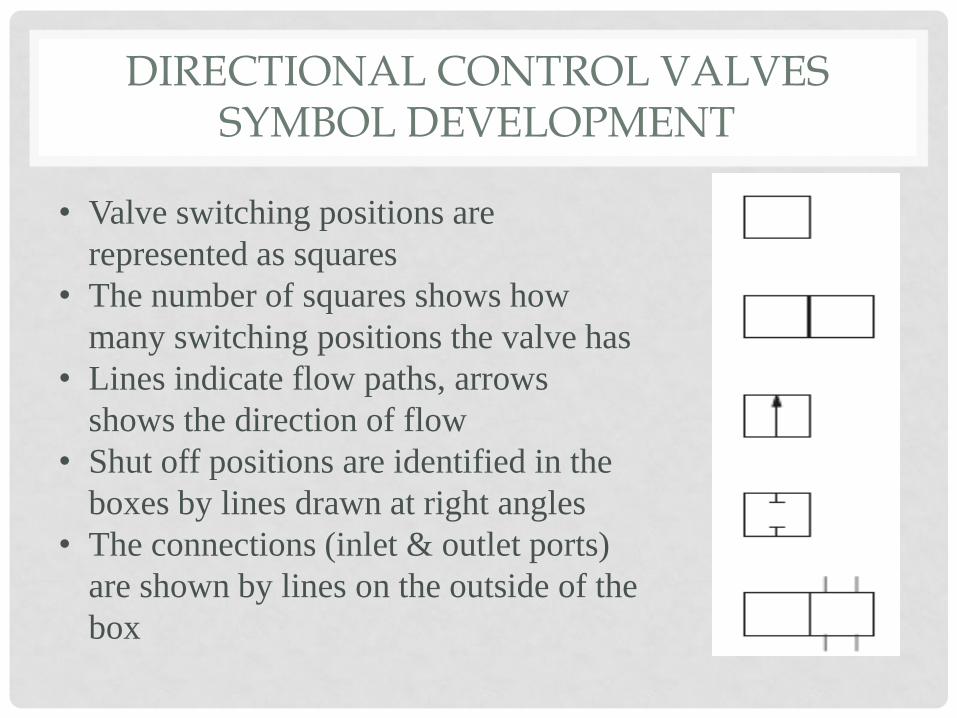
• Valve switching positions are
represented as squares
• The number of squares shows how
many switching positions the valve has
• Lines indicate flow paths, arrows
shows the direction of flow
• Shut off positions are identified in the
boxes by lines drawn at right angles
• The connections (inlet & outlet ports)
are shown by lines on the outside of the
box
DIRECTIONAL CONTROL VALVES SYMBOL DEVELOPMENT
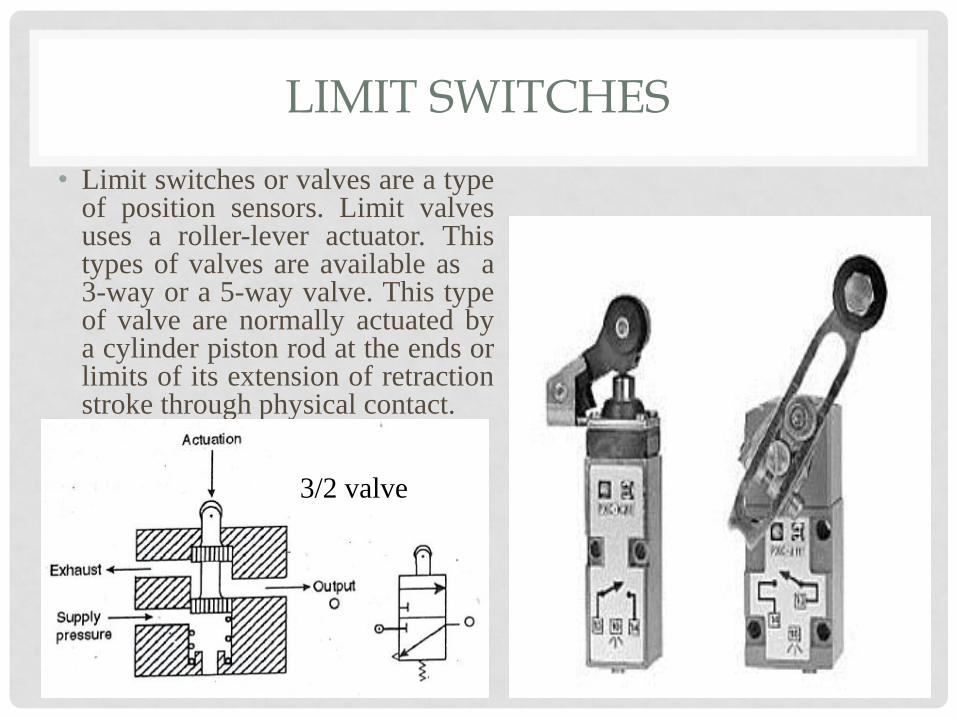
LIMIT SWITCHES
• Limit switches or valves are a type of position sensors. Limit valves uses a roller-lever actuator. This types of valves are available as a 3-way or a 5-way valve. This type of valve are normally actuated by a cylinder piston rod at the ends or limits of its extension of retraction stroke through physical contact.
3/2 valve
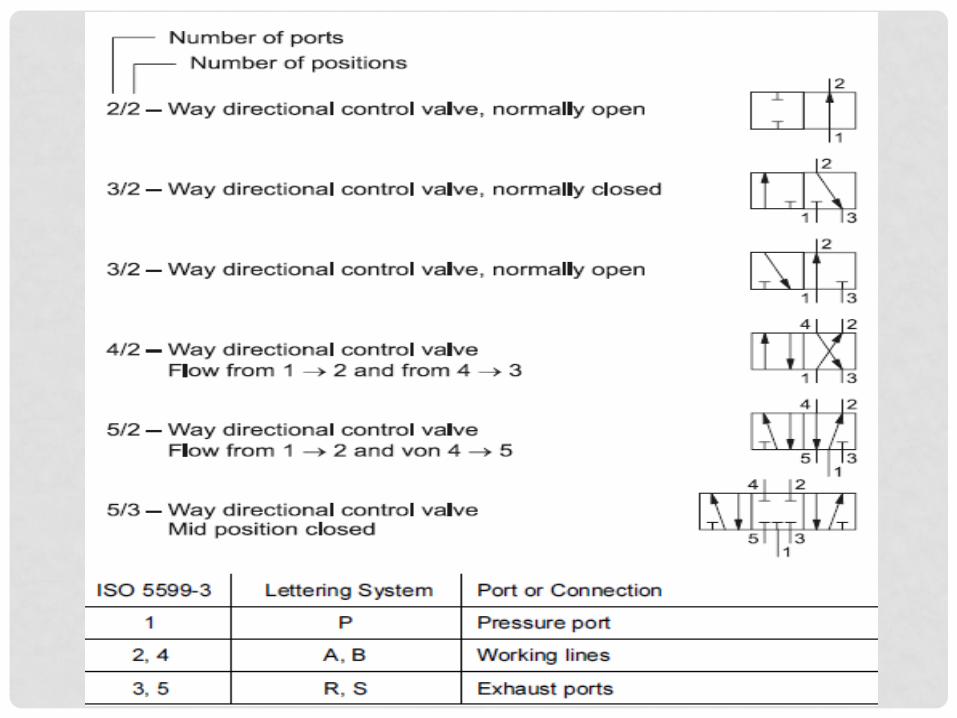
VALVE SYMBOL STRUCTURE
VALVE SYMBOL STRUCTURE
• The function of a valve is given by a pair of numerals
separated by a stroke, e.g. 3/2..
• The first numeral indicates the number of main ports.
These are inlets, outlets and exhausts but excludes signal
ports and external pilot feeds.
• The second numeral indicates the number of states the
valve can achieve.
VALVE SYMBOL STRUCTURE
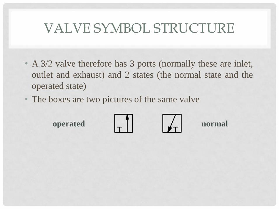
• A 3/2 valve therefore has 3 ports (normally these are inlet,
outlet and exhaust) and 2 states (the normal state and the
operated state)
• The boxes are two pictures of the same valve
normal operated

VALVE SYMBOL STRUCTURE
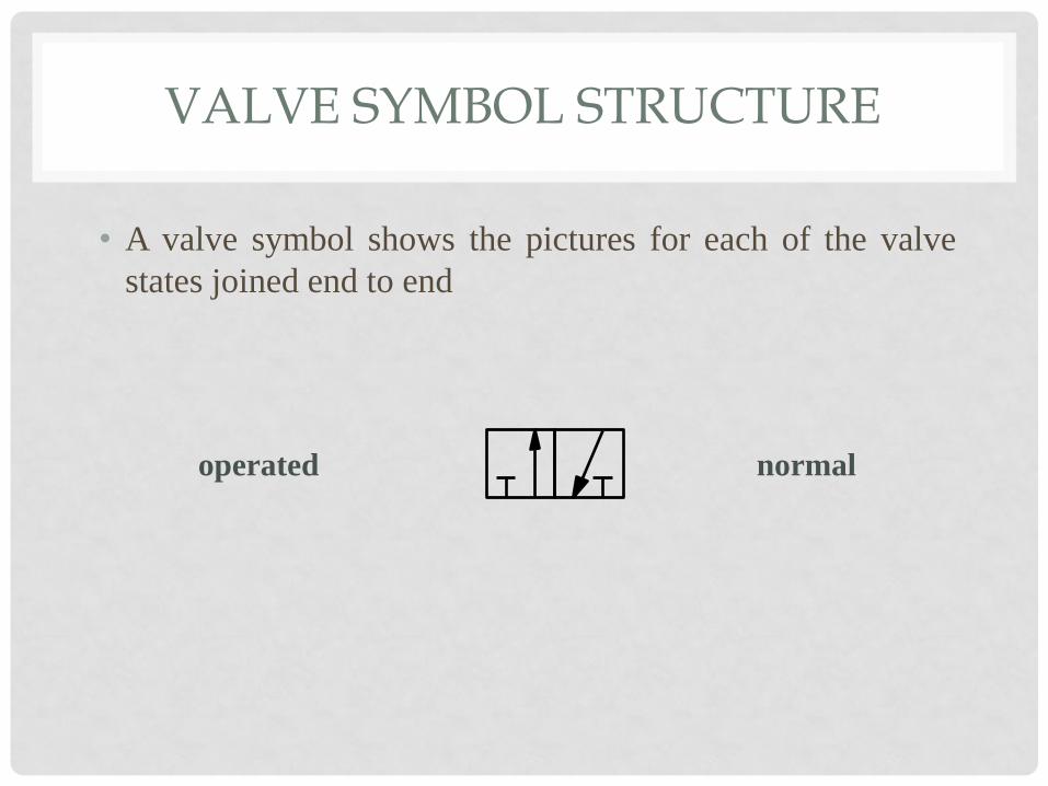
• A valve symbol shows the pictures for each of the valve
states joined end to end
normal operated
VALVE SYMBOL STRUCTURE
• A valve symbol shows the pictures for each of the valve
states joined end to end
normal operated
VALVE SYMBOL STRUCTURE
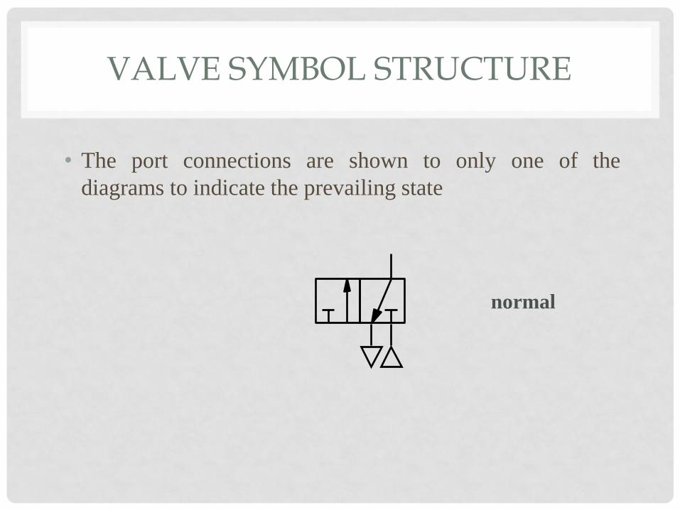
• The port connections are shown to only one of the
diagrams to indicate the prevailing state
normal
VALVE SYMBOL STRUCTURE
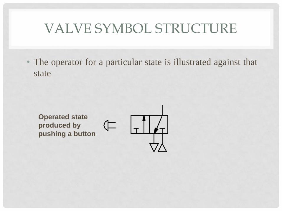
• The operator for a particular state is illustrated against that
state
Operated state
produced by
pushing a button

VALVE SYMBOL STRUCTURE
• The operator for a particular state is illustrated against that
state
Operated state
produced by
pushing a button
Normal state
produced by
a spring
VALVE SYMBOL STRUCTURE
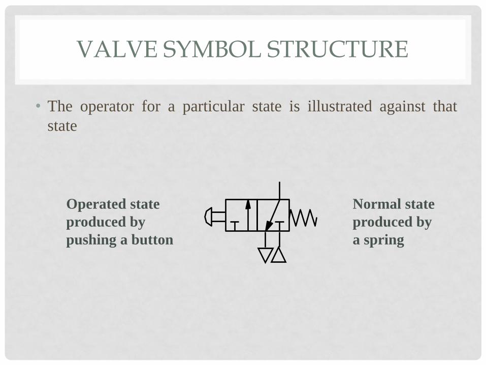
• The operator for a particular state is illustrated against that
state
Operated state
produced by
pushing a button
Normal state
produced by
a spring

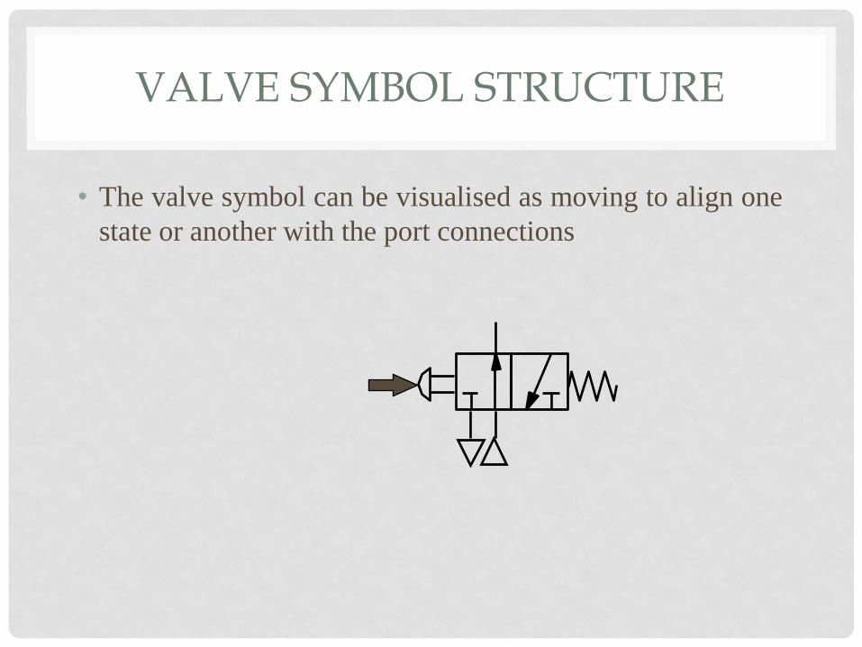
VALVE SYMBOL STRUCTURE
• The valve symbol can be visualised as moving to align one
state or another with the port connections
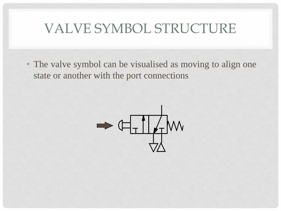
VALVE SYMBOL STRUCTURE
• The valve symbol can be visualised as moving to align one
state or another with the port connections
VALVE SYMBOL STRUCTURE
• The valve symbol can be visualised as moving to align one
state or another with the port connections
VALVE SYMBOL STRUCTURE
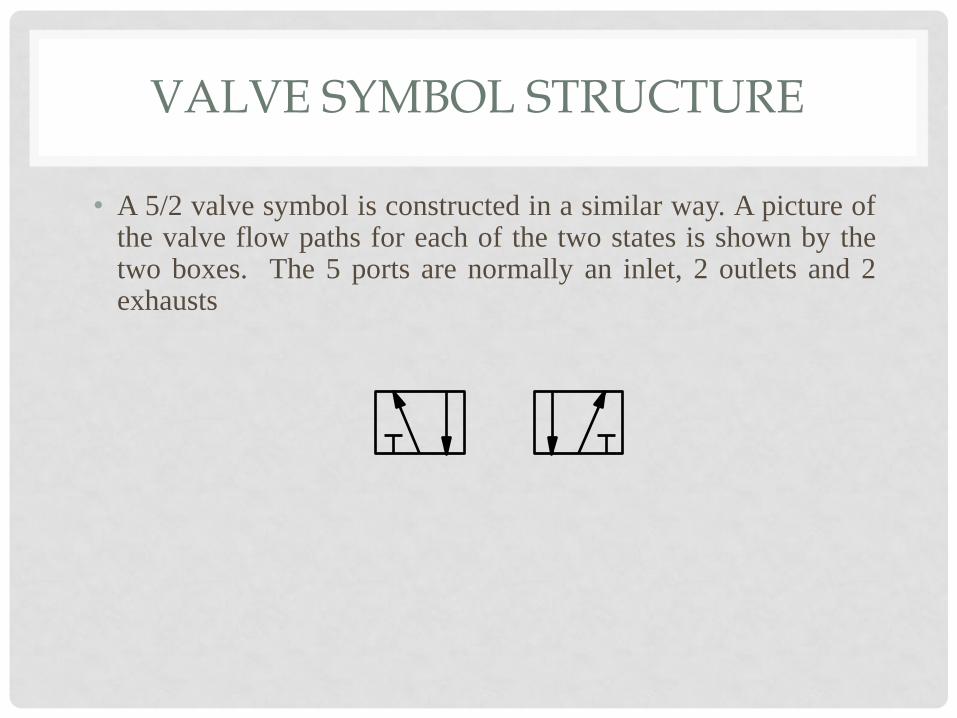
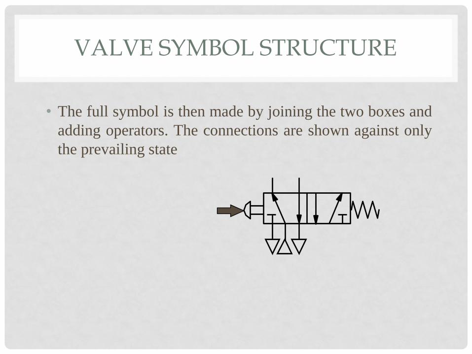
• A 5/2 valve symbol is constructed in a similar way. A picture of the valve flow paths for each of the two states is shown by the two boxes. The 5 ports are normally an inlet, 2 outlets and 2 exhausts
VALVE SYMBOL STRUCTURE
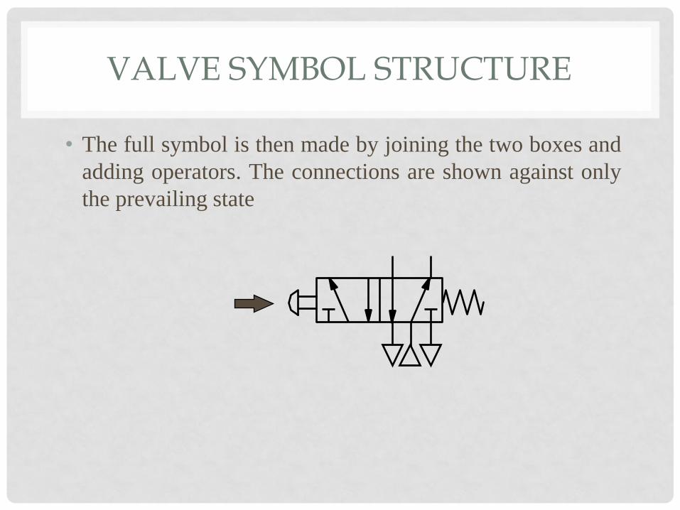
• The full symbol is then made by joining the two boxes and
adding operators. The connections are shown against only
the prevailing state
VALVE SYMBOL STRUCTURE
• The full symbol is then made by joining the two boxes and
adding operators. The connections are shown against only
the prevailing state

VALVE SYMBOL STRUCTURE
• The full symbol is then made by joining the two boxes and
adding operators. The connections are shown against only
the prevailing state
VALVE SYMBOL STRUCTURE
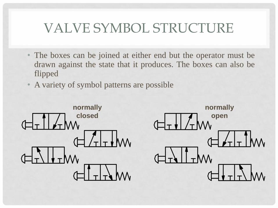
• The boxes can be joined at either end but the operator must be drawn against the state that it produces. The boxes can also be flipped
• A variety of symbol patterns are possible
normally
closed
normally
open
VALVE SYMBOL STRUCTURE
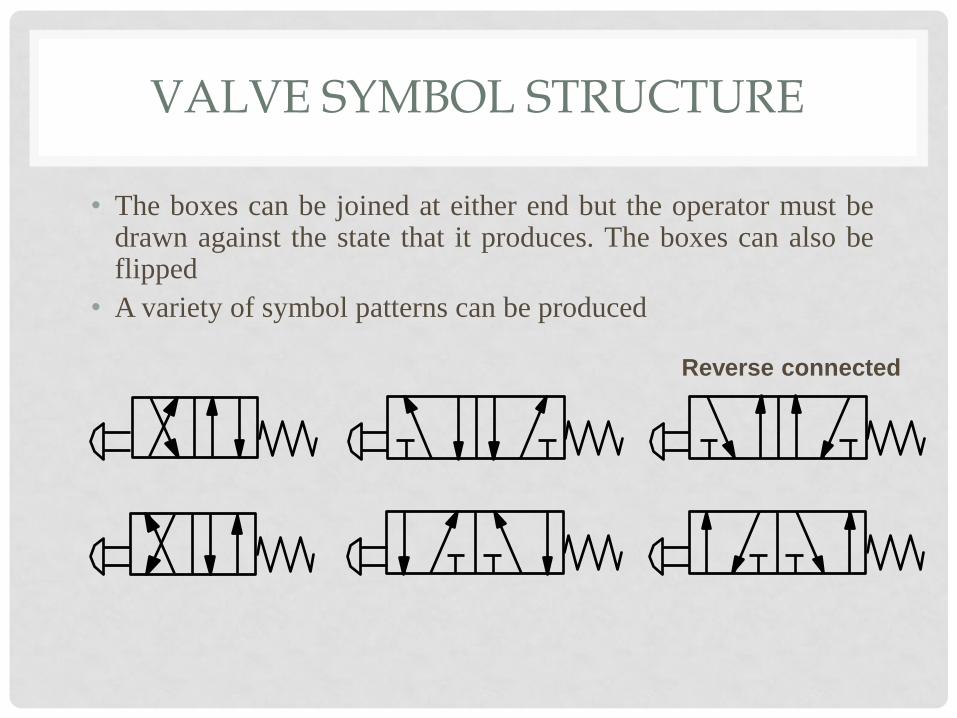
• The boxes can be joined at either end but the operator must be drawn against the state that it produces. The boxes can also be flipped
• A variety of symbol patterns can be produced
Reverse connected
VALVE FUNCTIONS
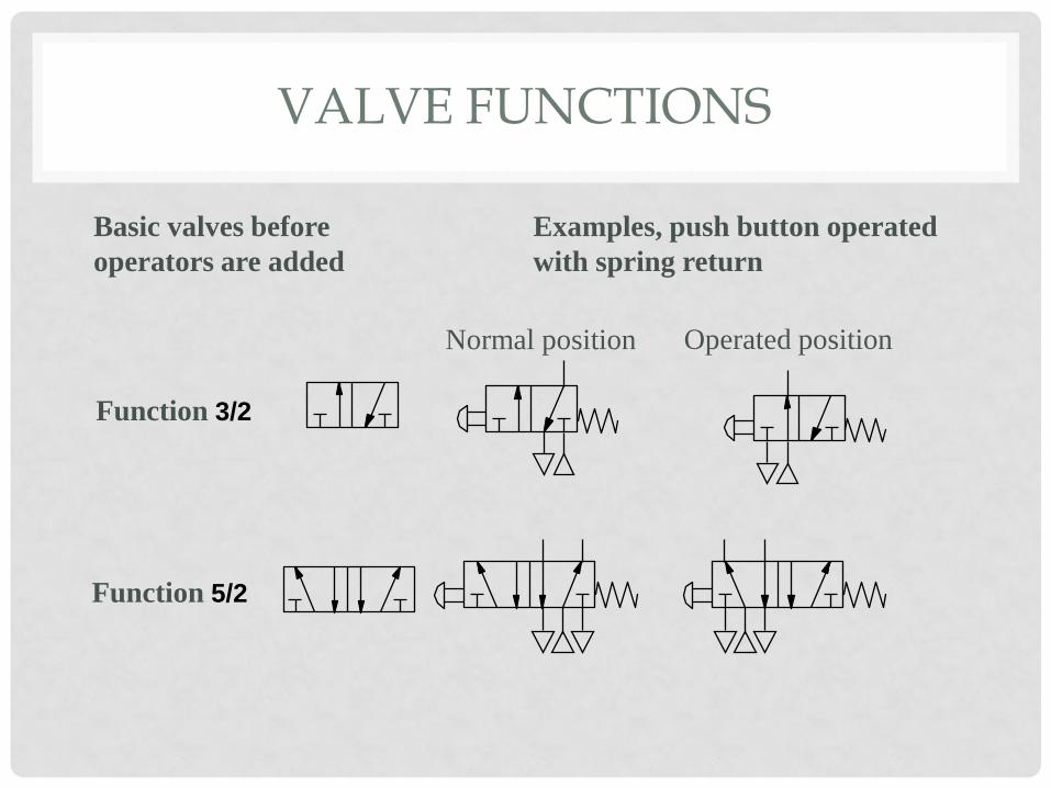
VALVE FUNCTIONS
Function 3/2
Normal position
Basic valves before
operators are added
Examples, push button operated
with spring return
Operated position
Function 5/2
OPERATORS
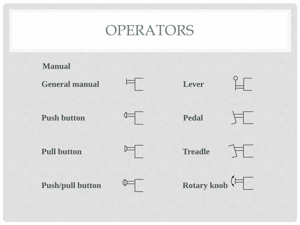
OPERATORS
General manual
Push button
Pull button
Push/pull button
Lever
Pedal
Treadle
Manual
Rotary knob

OPERATORS
Mechanical
Plunger
Spring normally
as a return
Roller
Uni-direction
or one way
trip
Pressure
Pilot pressure
Differential pressure
Detent in 3 positions

OPERATORS
Solenoid
direct
Solenoid pilot
Solenoid pilot
with manual override
and integral pilot
supply
Solenoid pilot
with manual
override and
external pilot
supply
Electrical
When no integral
or external pilot
supply is shown it
is assumed to be
integral
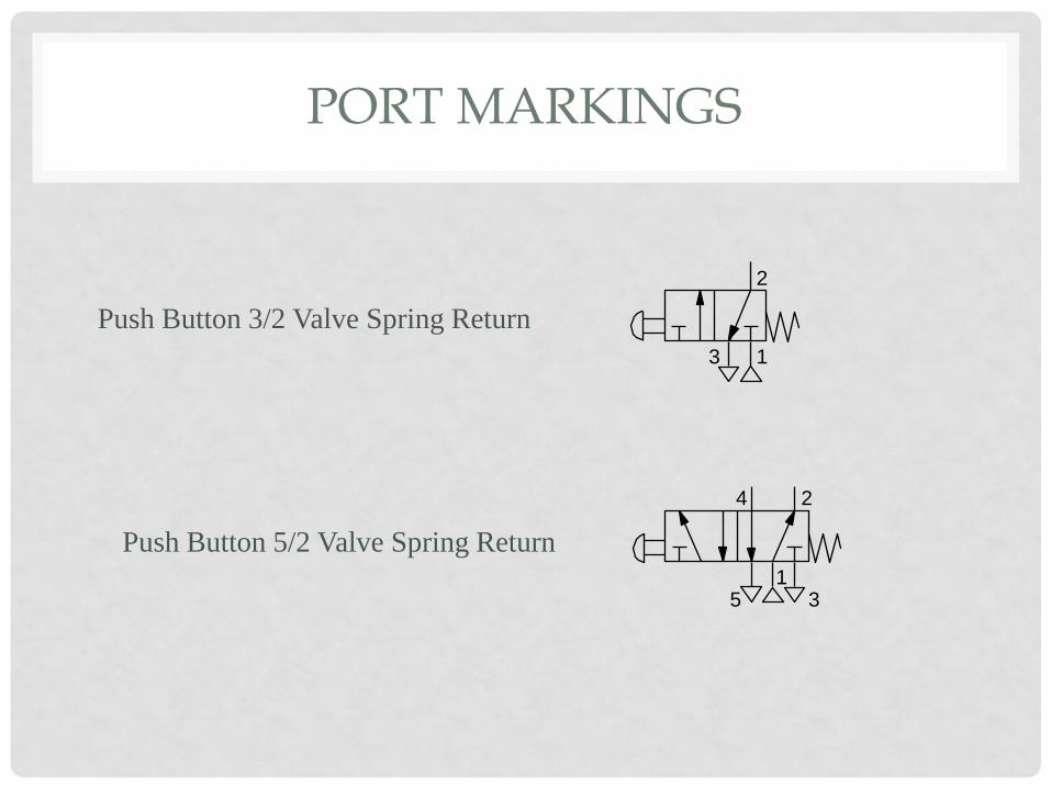
PORT MARKINGS
PORT MARKINGS
1
2 4
5 3
1
2
3
Push Button 3/2 Valve Spring Return
Push Button 5/2 Valve Spring Return

Actuators
An actuator is the component in a pneumatic system that does the work. There
are numerous types of actuators, powered by pressurized air. Plunge and
cylinder actuators are used frequently. The pressurized air is released into the
cylinder to move a piston forward as the air is forced into the chamber.
Examples of actuators at work are air-powered tools in construction and
dentistry.
Types of Actuator
Actuators may be grouped in a number of ways:
• Electromechanical
- Electromagnetic - The device has one coil which provides the field energy
and the energy to be transformed. The attractive force is unidirectional so a
return device of some type is needed, often a spring. Relays or solenoids are
used to switch - fans, head lights, horn, wipers.
- Electrodynamic - based on the (Lorenz) force generated when a current
carrying conductor (coil) is held in a magnetic field. - DC motors
• Fluid mechanical
- pneumatic. A common device is the pneumatic cylinder
- hydraulic. A common device is the hydraulic cylinder

The pneumatic cylinder has a significant role as a linear drive unit, due
to its
1. relatively low cost,
2. ease of installation,
3. simple and robust construction and
4. ready availability in various sizes and stroke lengths.
The pneumatic cylinder has the following general characteristics:
1. Diameters 2.5 to 320 mm
2. Stroke lengths 1 to 2000 mm
3. Available forces 2 to 45000 N at 6 bar
4. Piston speed 0.1 to 1.5 m/s
5. Single acting with return spring or Double acting

IMPORTANCE/ADVANTAGES OF PNEUMATIC CIRCUIT
• Pneumatics can be used for low cost industrial
applications – simple or complex.
• Welding and fabricating, press tools, automatic
machine tools, assembling, material handling, etc.
• Work function and control function is obtained by the
same power medium throughout the system
• Pneumatic circuits can be designed using number of
methods.
• Easy to expand once installed
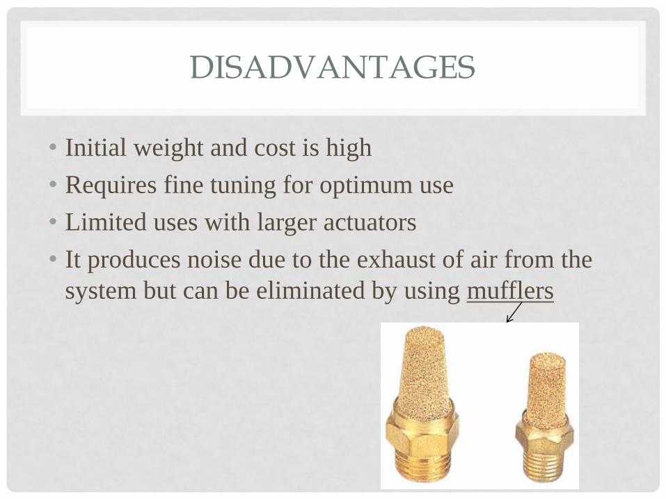
DISADVANTAGES
• Initial weight and cost is high
• Requires fine tuning for optimum use
• Limited uses with larger actuators
• It produces noise due to the exhaust of air from the
system but can be eliminated by using mufflers

CONSTRUCTION OF PNEUMATIC CIRCUITS
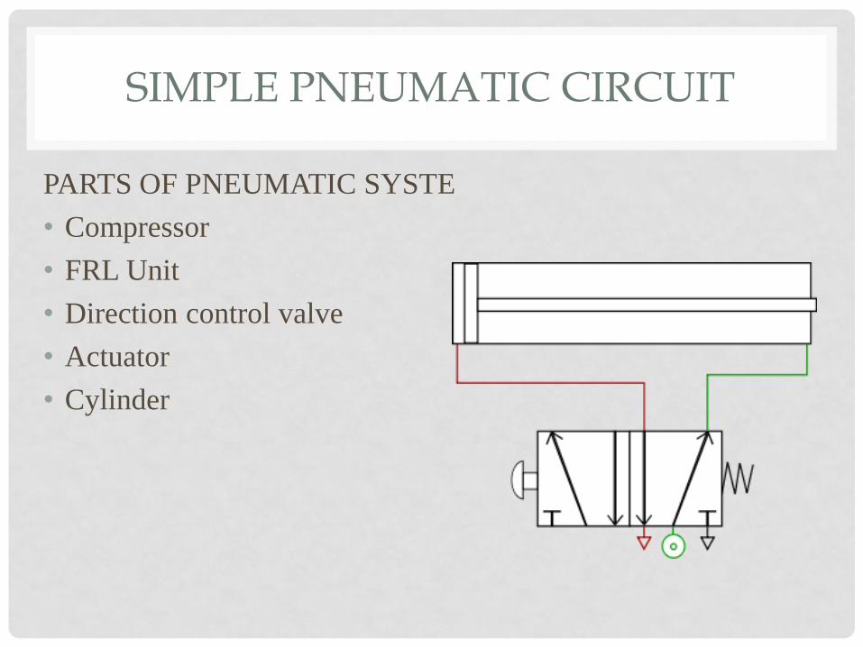
SIMPLE PNEUMATIC CIRCUIT
PARTS OF PNEUMATIC SYSTE
• Compressor
• FRL Unit
• Direction control valve
• Actuator
• Cylinder
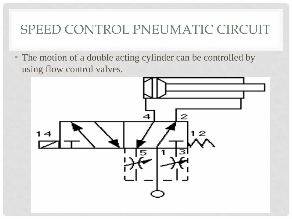
SPEED CONTROL PNEUMATIC CIRCUIT
• The motion of a double acting cylinder can be controlled by
using flow control valves.
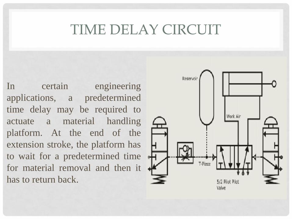
TIME DELAY CIRCUIT
In certain engineering
applications, a predetermined
time delay may be required to
actuate a material handling
platform. At the end of the
extension stroke, the platform has
to wait for a predetermined time
for material removal and then it
has to return back.
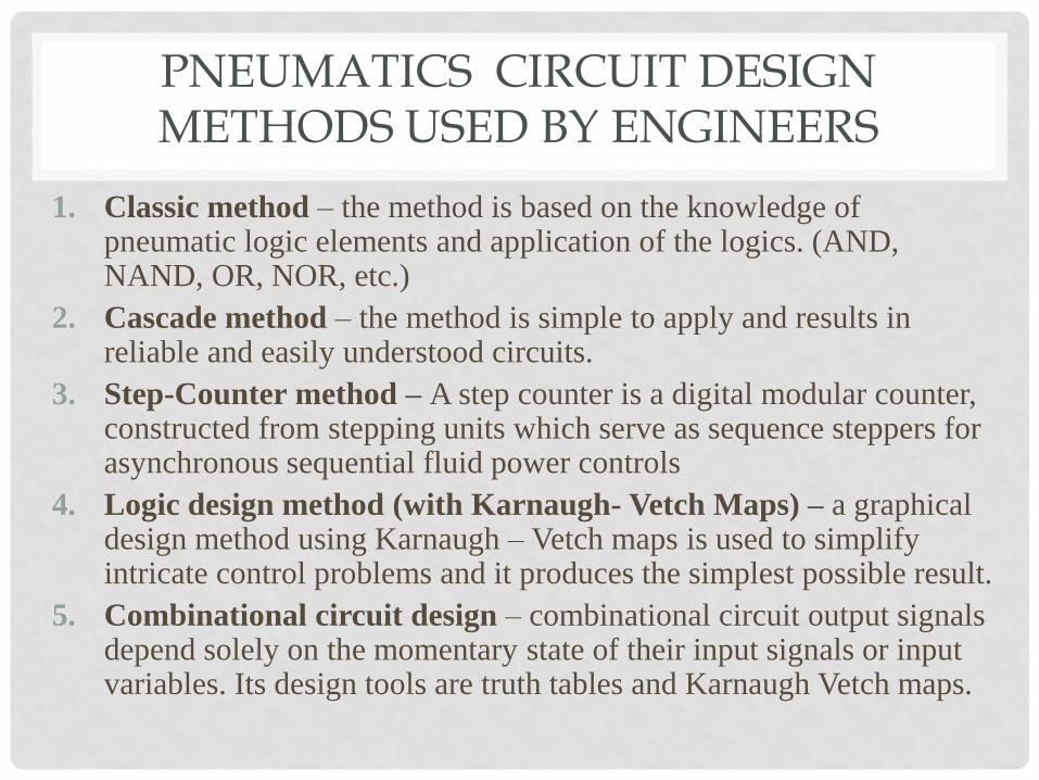
PNEUMATICS CIRCUIT DESIGN METHODS USED BY ENGINEERS
1. Classic method – the method is based on the knowledge of pneumatic logic elements and application of the logics. (AND, NAND, OR, NOR, etc.)
2. Cascade method – the method is simple to apply and results in reliable and easily understood circuits.
3. Step-Counter method – A step counter is a digital modular counter, constructed from stepping units which serve as sequence steppers for asynchronous sequential fluid power controls
4. Logic design method (with Karnaugh- Vetch Maps) – a graphical design method using Karnaugh – Vetch maps is used to simplify intricate control problems and it produces the simplest possible result.
5. Combinational circuit design – combinational circuit output signals depend solely on the momentary state of their input signals or input variables. Its design tools are truth tables and Karnaugh Vetch maps.

CLASSIC METHOD
• Each pneumatic element is a
logic element performing
various logic functions like
AND, NAND, OR, NOR etc.
• The principle of Boolean
algebra and De Morgan
theorem are employed to solve
problems in the analysis of
control logics
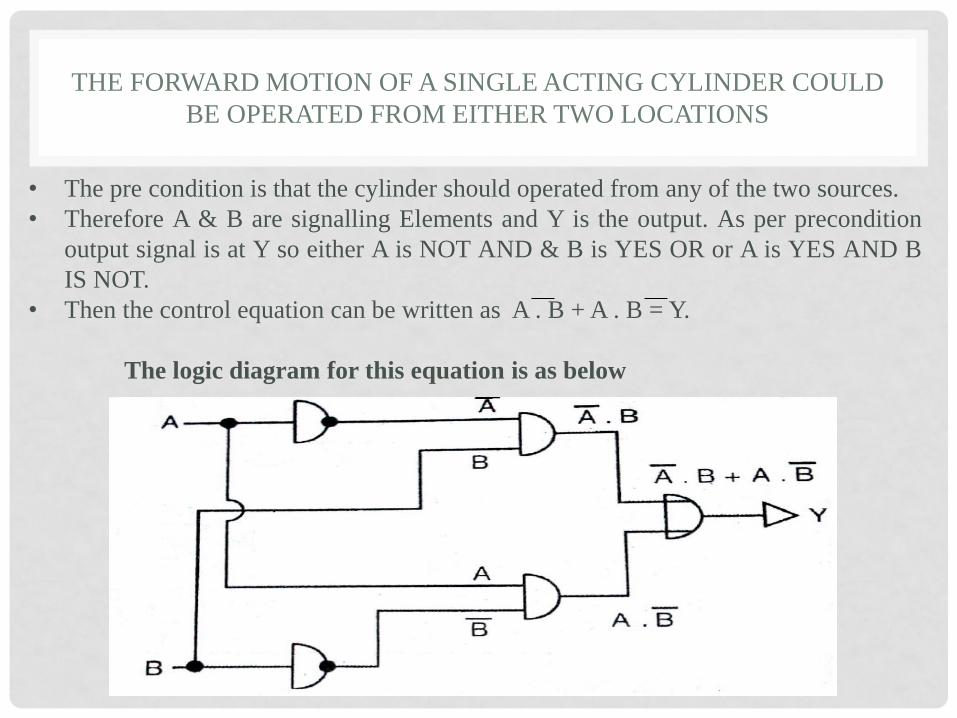
THE FORWARD MOTION OF A SINGLE ACTING CYLINDER COULD
BE OPERATED FROM EITHER TWO LOCATIONS
• The pre condition is that the cylinder should operated from any of the two sources.
• Therefore A & B are signalling Elements and Y is the output. As per precondition
output signal is at Y so either A is NOT AND & B is YES OR or A is YES AND B
IS NOT.
• Then the control equation can be written as A . B + A . B = Y.
The logic diagram for this equation is as below
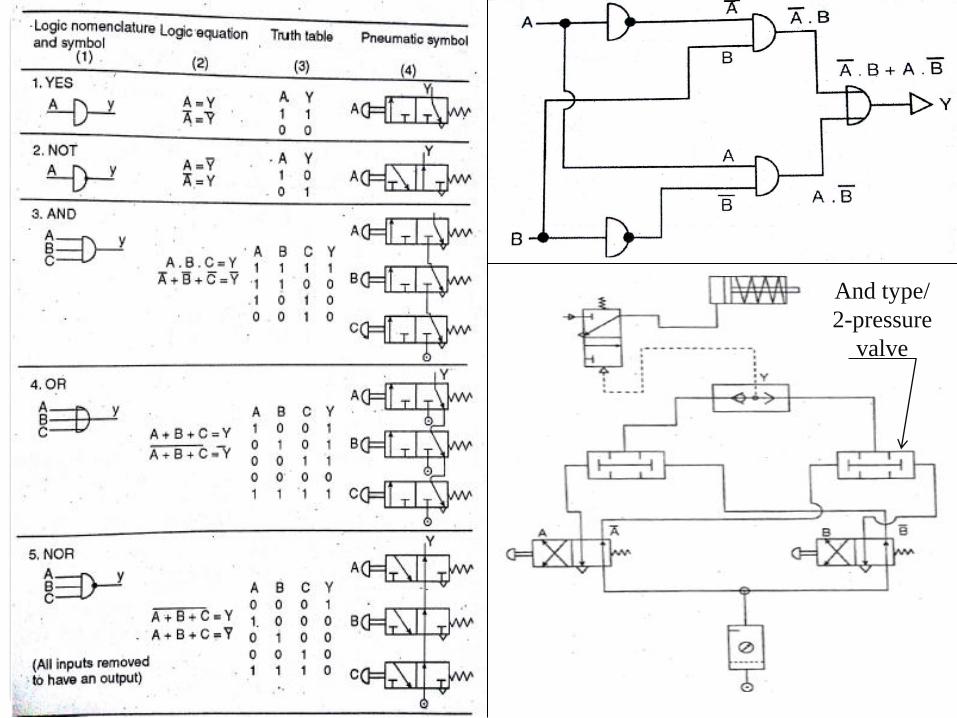
And type/
2-pressure
valve

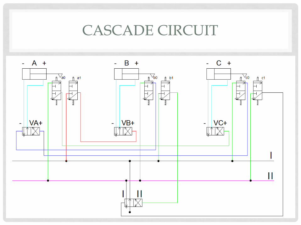
CASCADE METHOD TO DESIGN PNEUMATIC CIRCUIT OF A MATERIAL
HANDLING EQUIPMENT
• Designing a pneumatic circuit for material handling using 3
cylinders.
• Step 1 – Extension and Retraction of the system is denoted by
+ & - signs, therefore A+, A-, B+, B-, C+ & C-
• Step 2 – the sequence should be split in minimum no. of
groups without repeating. So C-,A+,B+ & B-,A-,C+
• Step 3 – Number of pressure lines are equal to the number of
groups, so 2. number of group valve is number of groups
minus one, so 1 group valve. Cylinder actuating valve are
equal to the no. of cylinders.
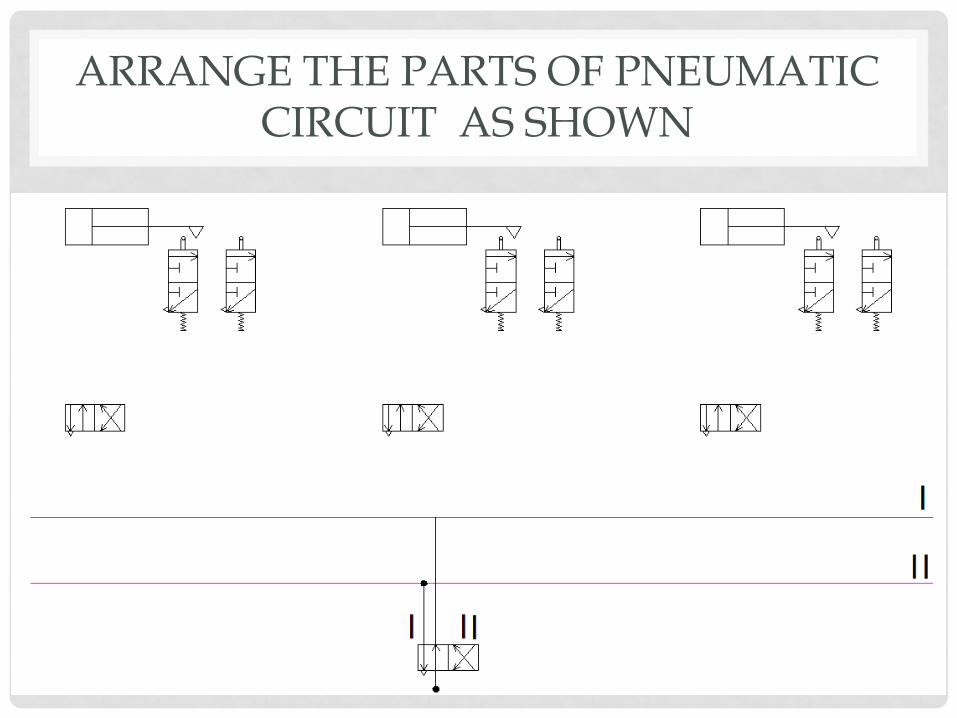
ARRANGE THE PARTS OF PNEUMATIC CIRCUIT AS SHOWN
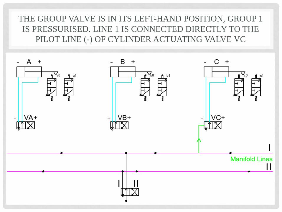
THE GROUP VALVE IS IN ITS LEFT-HAND POSITION, GROUP 1
IS PRESSURISED. LINE 1 IS CONNECTED DIRECTLY TO THE
PILOT LINE (-) OF CYLINDER ACTUATING VALVE VC
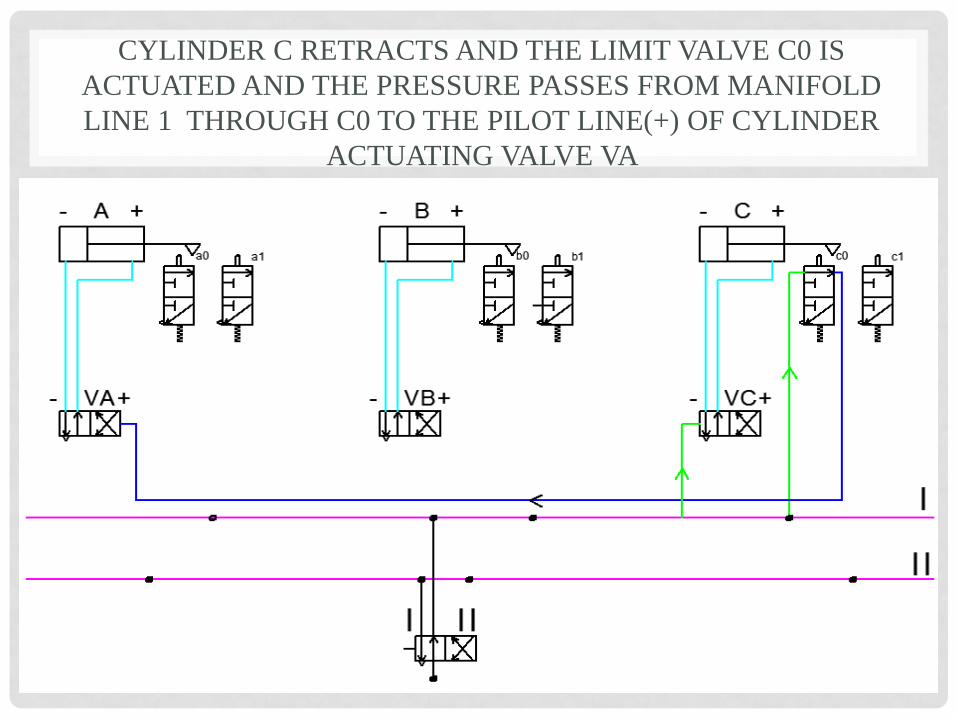
CYLINDER C RETRACTS AND THE LIMIT VALVE C0 IS
ACTUATED AND THE PRESSURE PASSES FROM MANIFOLD
LINE 1 THROUGH C0 TO THE PILOT LINE(+) OF CYLINDER
ACTUATING VALVE VA
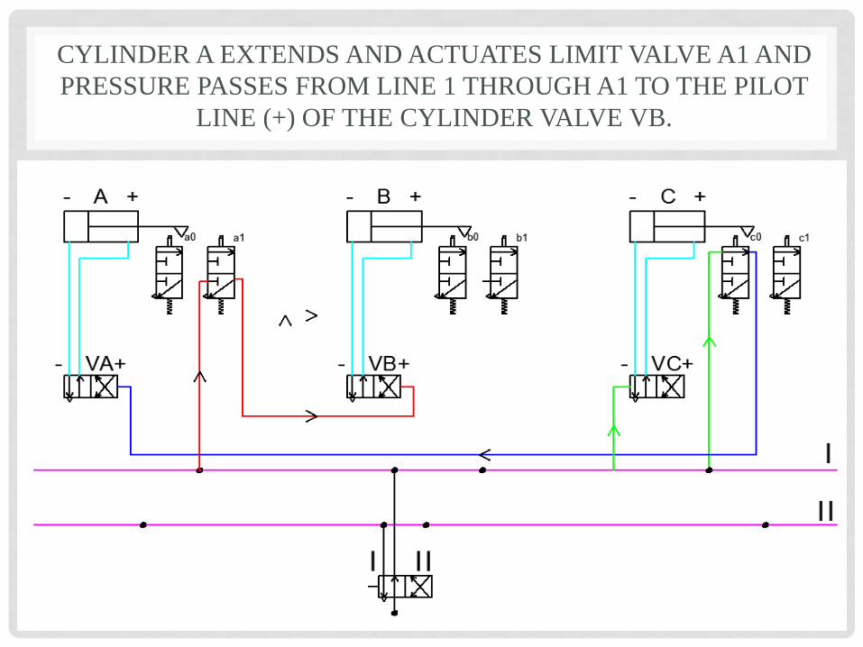
CYLINDER A EXTENDS AND ACTUATES LIMIT VALVE A1 AND
PRESSURE PASSES FROM LINE 1 THROUGH A1 TO THE PILOT
LINE (+) OF THE CYLINDER VALVE VB.
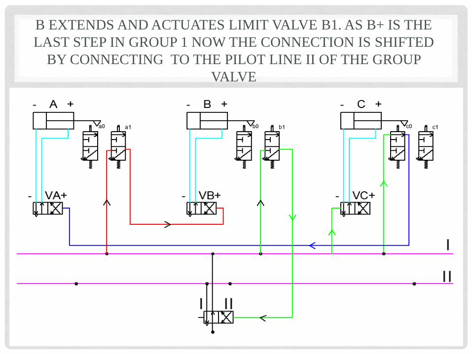
B EXTENDS AND ACTUATES LIMIT VALVE B1. AS B+ IS THE
LAST STEP IN GROUP 1 NOW THE CONNECTION IS SHIFTED
BY CONNECTING TO THE PILOT LINE II OF THE GROUP
VALVE

LINE II IS CONNECTED TO THE (-) OF CYLINDER ACTUATING
VALVE VB, SO B RETRACTS AND VALVE B0 IS ACTUATED
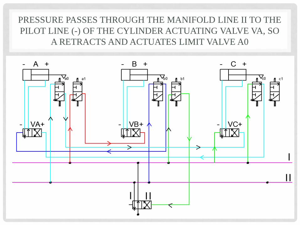
PRESSURE PASSES THROUGH THE MANIFOLD LINE II TO THE
PILOT LINE (-) OF THE CYLINDER ACTUATING VALVE VA, SO
A RETRACTS AND ACTUATES LIMIT VALVE A0
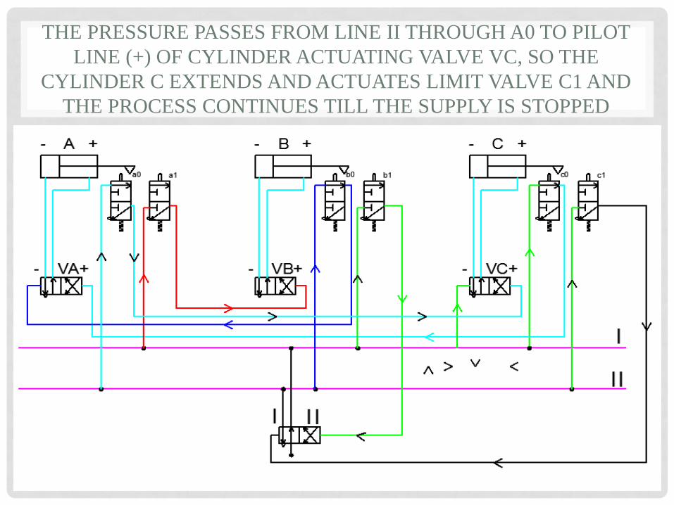
THE PRESSURE PASSES FROM LINE II THROUGH A0 TO PILOT
LINE (+) OF CYLINDER ACTUATING VALVE VC, SO THE
CYLINDER C EXTENDS AND ACTUATES LIMIT VALVE C1 AND
THE PROCESS CONTINUES TILL THE SUPPLY IS STOPPED

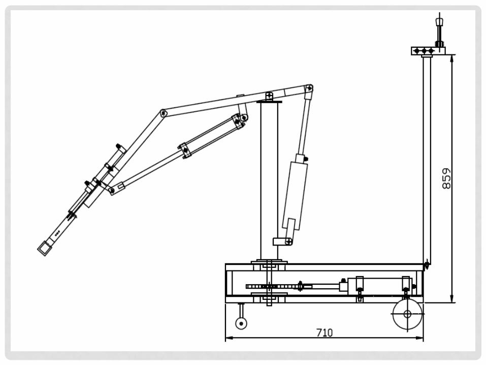
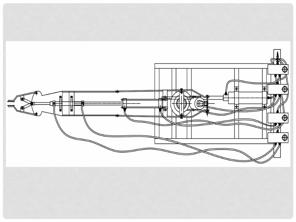
MATERIAL HANDLING EQUIPMENT
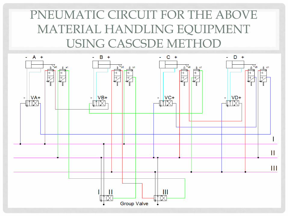
PNEUMATIC CIRCUIT FOR THE ABOVE MATERIAL HANDLING EQUIPMENT
USING CASCSDE METHOD