84 pulse converter, design and simulations with …...84 pulse converter, design and simulations...
TRANSCRIPT
6
84 Pulse Converter, Design and Simulations with Matlab
Antonio Valderrábano González1, Juan Manuel Ramirez2 and Francisco Beltrán Carbajal3
1Universidad Politécnica de la Zona Metropolitana de Guadalajara, 2Cinvestav, Unidad Guadalajara,
3Universidad Autónoma Metropolitana, Plantel Azcapotzalco, Departamento de Energía México
1. Introduction
Flexible Alternating Current Transmission System (FACTS) devices have been proposed for fast dynamic control of voltage, impedance, and phase angle in high-voltage AC lines. The application of this technology has opened new and better opportunities for an appropriate transmission and distribution control. The efforts performed all over the world to improve the power quality have originated several power conditioners, which by themselves contribute to power degradation due to switching of the semiconductor devices, and harmonic effects generated in the converters. Thus, big elements have been used as filters, pursuing to have appropriate power quality with low extra noise. Because of that, this technology has not been probed in stringent applications such as hospitals or airports, which are two of the environments to consider. The series and shunt power systems compensation are used with the purpose of improving the operating conditions; respect to the voltage, the compensation has the purpose of handling reactive power to maintain bus voltages close to their nominal values, reduce line currents, and reduce system losses. The voltage magnitude in some buses may be controlled through sophisticated and versatile devices such as the StatCom, which is the smaller and most cost effective FACTS device in many applications (Hingorani, 2007), and is a power reactive source (Acha et al., 2004; Song & Johns, 1999). By regulation of the StatCom’s output voltage magnitude, the reactive power exchanged between the StatCom and the transmission system can be controlled (CIGRE, 1998; Davalos, 2003; El-Moursi & Sharaf, 2005; Hingorani & Gyugyi, 2000;Wang, 2000). This Chapter describes how the assembling of a Voltage Source Converter (VSC) that meets the IEEE Std. 519-1992 (IEEE Recommended Practices and Requirements for Harmonic Control in Electrical Power Systems) is performed, and emphasizes its development through Matlab simulations. The low Total Harmonic Distortion (THD) that this VSC produces allows this power conditioner to be considered for its use on stringent applications or in the reactive power compensation and the power quality improvement. The reinjection principle used, makes this proposal to be considered as an affordable solution to the sinusoidal synthesization due to the reduced number of switches needed. The reinjection transformer is one of the most important elements in this configuration, and it can have a wide turn ratio’s variation without leading out the special application standards.
www.intechopen.com

Applications of MATLAB in Science and Engineering
124
The conventional PI controllers applied to maintain the output voltage of the StatCom around nominal conditions exhibit poor performance under severe disturbances, where the error signal jumps with big steps in magnitude. The strategy followed in this research, employs the error and error’s variation to break down the control action into smaller sections that can be selected according to simple rules. Simulation results evidence the proposal’s suitability validating each part of the device.
2. 84-pulses StatCom
The StatCom is a power electronic-based Synchronous Voltage Generator (SVG) able to provide fast and continuous capacitive and inductive reactive power supply. It generates a three-phase voltage, synchronized with the transmission voltage, from a DC energy source, and it is connected to the Electrical Power System (EPS) by a coupling transformer. The regulation on the magnitude of the StatCom's output voltage, gives rise to the reactive power exchange between the StatCom and the transmission system. The StatCom's basic structure illustrated on Fig. 1 consists of a step-down transformer, a three-phase voltage source converter (VSC), and a DC capacitor (CIGRE, 1998; Davalos, 2003; El-Moursi & Sharaf, 2005; Norouzi & Shard, 2003; Song & Johns, 1999).
Fig. 1. StatCom’s Basic Structure
This chapter is focused on the internal structure of the proposed VSC to get a low THD output voltage. Likewise, the main aspects to connect the StatCom to the grid are reviewed.
2.1 Reinjection configuration
There are three main strategies to build a Voltage Source Converter (VSC): (i) the multipulse; (ii) the multilevel; (iii) and the pulse width modulation (PWM) (Pan & Zhang,
www.intechopen.com

84 Pulse Converter, Design and Simulations with Matlab
125
2007; Liu et al., 2004). In the multipulse strategy, the period of the signal is broken down into equal sized parts in relation to the pulse number. The switches are triggered once per cycle at the fundamental frequency, and the amplitude on each pulse is controlled mainly by the output magnetic stage. The more pulses produces the less output Total Harmonic Distortion (THD). In the multilevel strategy, the DC source has to be broken down into parts of equal amplitude (x), given rise to a 2x-1 levels signal. Switches commute once per cycle at the fundamental frequency. The THD depends on the amount of DC sources or divisions available in the DC link. On the other hand, the PWM technique uses fast commutations to reach a low THD. The faster commutations are, the lower THD. However, it is limited due to the commutation speed of the switches and requires always an output filter coupled to the grid. This research deals with a combination of the first two strategies with emphasis on the use of multipulse configuration in order to reach the minimum total harmonic distortion. There is a difference on the twelve-pulse converter used in this work, respect to the standard twelve-pulse converter. The DC source is not common to both six-pulse modules. In this proposition, a positive multipulse signal between the main terminals of the first six-pulse converter and another positive multipulse signal with opposite phase between the main terminals of the second six-pulse converter are connected. In order to have a neutral point, the negative of the first converter is connected to the positive of the second converter, as presented on Fig. 2. Each branch in the six-pulse converters must generate electrical signals with 120° of displacement between them; the upper switch is conducting while the lower one is open and vice versa (180° voltage source operation) (Krause et al., 2002).
Fig. 2. (a) 12-pulse Traditional Scheme, (b) 12-pulse Reinjection Scheme fed by a 7 level converter.
A 30° displacement in the firing sequence of both converters must be considered.
Transformer’s turn ratios are 1:1 and 1: 3 on the YY and YΔ transformers, respectively. In
order to operate the VSC in special applications such as airports or hospitals, on this
chapter, an 84 level voltage signal is proposed, generated through a 7 level auxiliary circuit
www.intechopen.com

Applications of MATLAB in Science and Engineering
126
operating as a re-injection scheme. The auxiliary circuit is common to the three phases,
reducing the number of extra components. The topology to provide the pulse multiplication
is detailed in (Pan & Zhang, 2007; Liu et al., 2003, 2004a, 2004b; Han et al., 2005;
Voraphonpiput & Chatratana, 2004), and illustrated in Fig. 3.
Fig. 3. 84-pulse StatCom structure
2.2 Total harmonic distortion
In order to apply the seven level inverter output voltage to feed the standard twelve-pulse
converter, special care should be paid to not inject negative voltage into YV orV ; notice the
inclusion of the injection transformer between both arrays. Thus, input voltages in the six-
pulse converter may be regulated by adjusting the injection voltage iU by:
Y DC iV V U (1)
DC iV V U (2)
The injection voltage is determined by the seven level inverter switching pattern and the
injection transformer turns ratio. When voltages YV andV are used as inputs to the six-
pulse converters, a cleaner VSC output voltage comes about. Fig. 4 exhibits the strategy to
generate YUV and UV as the interaction of the seven level output and the corresponding six-
pulse signals. These signals have been obtained from an electrical simulation developed in
PLECS®, within Matlab /Simulink environment.
www.intechopen.com

84 Pulse Converter, Design and Simulations with Matlab
127
Fig. 4. Mixing seven level, six-pulse signals, and transformer ratios to attain YUV and UV .
Through the 1:1 ratio in the YY TRANSFORMER, and 1 : 3 for the Y TRANSFORMER,
adding their corresponding output signals, the 84-pulses line-to-neutral signal VU emerges,
with the harmonic spectrum in Fig. 5 (linear scale) and in Fig. 6 (logarithmic scale).
Fig. 5. 84-pulses line-to-neutral output voltage and harmonic content (linear scale)
Fig. 6. 84-pulses line-to-neutral output voltage and harmonic content (logarithmic scale)
www.intechopen.com

Applications of MATLAB in Science and Engineering
128
The StatCom’s phase voltage VU is an odd symmetric signal, so that the Fourier’s even terms become zero. Thus,
2 1
1
sin 2 1nU U
n
V t V n t
(3)
2 1 2 1 2 1
4
3 (2 1)nU n n
VV A aB
n (4)
2 1
1 12 2 cos 2 1 2 3 cos 2 1
3 6nA n n (5)
20
2 10
cos 2 142
n ii
iB Coeff n
(6)
3, 1, 1, 1, 1, 1, 1, ...
3 3 , 3 1, 3 1, 3 1, 3 1, 3 1, 3 1, ...
3, 3 2, 3 2, 3 2, 3 2, 3 2, 3 2
Coeff
(7)
being a the re-injection transformer’s turns ratio. The 84-pulse signal value (VU) depends on the injection transformer turns ratio a, which is determined in order to minimize the THD, defined by (Pan et al., 2007, IEEE Std. 519-1992)
1
2
2
2
Un
U
nVU
V
THDV
(8)
The minimization of THD yields the parameter a. In this research such calculation has been carried out in Matlab with n = 7200, and increments Δa = 0.0001. With these parameters, the
minimum THD becomes 2.358% with 0.5609a , value employed on the previous figures.
The distortion limits according to the IEEE Std. 519 indicate that the allowed THD in voltage
is 10% in dedicated systems, 5% in general systems, and 3% for special applications as
hospitals and airports .
Table 1 presents the minimum THD in the output voltage produced with several multipulse
configurations. The THD produced through this proposition allows its use even in
applications with stringent quality requirements; it exhibits less dependence to variations on
the transformer’s turns ratio a , which can have variations until 12.5% to get a maximum
THD lower than 3%. This means that a strict reinjection transformer’s turn ratio is not
needed to get a THD within a stringent condition. Fig. 7. illustrates the dependence of the
THD with respect to variations in the re-injection transformer’s turn ratio a. All these values
had been obtained using Matlab.
2.3 StatCom’s arrangement
Connecting the improved VSC to the system for reactive compensation requires several points to be taken into account. This section deals with such details using Fig. 3 as the main
www.intechopen.com

84 Pulse Converter, Design and Simulations with Matlab
129
scheme, including a coupling transformer 13.8 kV : 13.8 kV, and considering the transmission line parameters presented on Table 2, at 75°C.
Number of pulsesTHD (%)
12 15.22
24 7.38
48 3.8
60 3.159
84 2.358
Table 1. Minimum THD produced through the multipulse VSC
Fig. 7. Dependence of the THD with respect to the reinjection transformer’s turn ratio
Parameter Value
Conductor code name Grosbeak Aluminum Conductor Composite Core (ACCC)
Voltage rating (peak) 13.8kV
Resistance 0.0839 Ω/ km
Inductive Reactance 0.2574 Ω / km
Line length 50km
Load Resistance 202.5 Ω
Load Inductive Reactance 0.6H
Table 2. Transmission Line parameters used.
www.intechopen.com

Applications of MATLAB in Science and Engineering
130
If we pursue to eliminate the active power exchange between the StatCom and the system, taking into consideration the reactive power compensation, the DC voltage sources are replaced by capacitors. Secondly, it must be ensured that the StatCom’s frequency and phase angle are equal to
the system ones; these parameters will be obtained by using a novel synchronizing
arrangement able to detect instantaneously the phase angle. The seven level inverter must
switch at six times the frequency of the six-pulse converters to ensure phase and
frequency.
The digital signal processor (DSP)-control implementation must take the voltage levels
needed for the ADC (analog/digital converter) to detect the signals with appropriate
precision, and must refresh the output data before to take new samples in order to be
considered real time. It is also needed to provide isolation from the power stage.
2.3.1 Synchronization of signals
The Phase-Locked-Loop (PLL) is the synchronizing circuit responsible for the determination
of the system’s frequency and phase-angle of the fundamental positive sequence voltage of
the controlled AC bus(Aredes, & Santos Jr., 2000). The PLL utilizes the Stationary Reference
Frame in order to reduce computational costs, and helps to improve the system’s dynamic
performance (Cho & Song, 2001). Digital PLL is an algorithm able to detect the fundamental
component of the phase-voltages, synchronizing the output signal to the frequency and
phase of the input one. This algorithm does not require a zero crossing detection routine for
the input voltage or the generation of internal reference signals for the input current (Mussa
& Mohr, 2004). The PLL strategy used employs a correction value determined by the signs
of and , which is added to a 1tan function, Fig. 8.
abc -> -atan( / )
Sign Correction
value
2
+
OPTIMIZED
PLL
Fig. 8. PLL Strategy
This block synchronizes the PLL’s zero output with respect to the startup of the signal,
when the signal presents its minimum value, Fig. 9.
www.intechopen.com

84 Pulse Converter, Design and Simulations with Matlab
131
Fig. 9. , , and PLL-output
2.3.2 Firing sequence
The second block is the six-pulse generator, which is responsible to generate the pulse sequence to fire the three-phase IGBT array. It consists of an array of six-pulse spaced 60° each other. In this block, the IGBT will operate at full 180° for the on period and 180° for the off period. Any disturbance in the frequency will be captured by the synchronizing block, preventing errors. The falling border in the synchronizing block output signal is added to a series of six 60° spaced signals that would be sent to the opto-coupler block gate, which will feed each six-pulse converter. The off sequence turns out in a similar way but waiting 180° to keep the same duration on and off in each IGBT, Fig. 10.
Fig. 10. Firing sequence for the six-pulses modules
www.intechopen.com

Applications of MATLAB in Science and Engineering
132
2.3.3 Seven level generator
In order to produce the pulse sequence needed to generate the seven level inverter, six times
the frequency of the six-pulse generator should be ensured beginning at the same time. This
is achieved by monitoring the falling border in the novel PLL output signal, and using it
along with the modulus operator with the 3 argument. This signal will be the period for
the seven level generator, which will modify its state each 42 rad. Fig. 11 depicts the
asymmetric pulse sequence for such seven level inverter, along with the seven level voltage
for a complete sinusoidal cycle and a 3 zoom-in, in order to observe the detailed pulse
signals.
Fig. 11. Seven level gate signals
2.3.4 Angle’s control circuit
The reactive power exchange between the AC system and the compensator is controlled by
varying the fundamental component magnitude of the inverter voltage, above and below
the AC system level. The compensator control is achieved by small variations in the
semiconductor devices’ switching angle, so that the fundamental component of the voltage
generated by the inverter is forced to lag or lead the AC system voltage by a few degrees.
This causes active power to flow into or out of the inverter, modifying the value of the DC
capacitor voltage, and consequently the magnitude of the inverter terminal voltage, and the
resultant reactive power (Davalos, 2003). The angle’s control block diagram is described in
(Cho & Song, 2001) for a PI controller, and depicted in Fig. 12. The inputs are the line-to-line
voltages of the controlled AC bus prior to the coupling transformer. The reference voltage
VREF is chosen as the RMS value for a pure sinusoidal three phase signal, which is 1.5
times the peak of the line voltage. This value is compared to the filtered RMS StatCom
voltage output (VRMS) multiplied by the coupling transformer’s turn ratio; it may contain
an oscillating component. The output signal corresponds to the displacement angle of the
generated multipulse voltage, with respect to the controlled AC bus voltage (primary
voltage of the converter transformer). The low-pass-filter (LPF) is tuned to remove the
characteristic harmonic content in the multipulse configuration; for the twelve-pulse it
begins with the 11th harmonic. The PI controller has a limiting factor by dividing the error
www.intechopen.com

84 Pulse Converter, Design and Simulations with Matlab
133
signal by the reference voltage VREF in order to have the signal with a maximum value
of -1 when the StatCom output is equal to zero. In the following chapter special attention is
paid to the fuzzy segmented PI controller.
Fig. 12. StatCom’s power angle control
3. Control strategy
Conventional PI or PID regulators have been applied to control the StatCom’s output voltage around nominal conditions or subject to disturb like voltage unbalance (Hochgraf & Lasseter, 1998; Blazic & Papic, 2006; Li et al., 2007; Cavaliere et al., 2002). Such controllers may exhibit poor performance under other disturbances, where the error signal jumps with big steps in magnitude. In this research, it is desireable to find a controller that can deal with most of the problems detailed in (Seymour & Horsley, 2005). The strategy followed employs the error and error’s variation to break down the control action in smaller sections that can be selected according to simple rules.
3.1 Segmented PI controller
The complete system presented on Fig. 2 was tested in Matlab under several disturbances using a PI controller tunned for steady state operation. Special attention was paid to measure the error and estimate the error’s increment when the disturbances were applied. It was verified that a motor startup is a quite demanding situation to test the StatCom’s performance, so it was used to define the membership function limits. For simplicity on the controller design, crisp membership functions were used to describe seven linguistic variables similarly to the fuzzy set notation as follows:
www.intechopen.com

Applications of MATLAB in Science and Engineering
134
Linguistic Variable Meaning
NB negative big
NM negative medium
NS negative small
Z Zero
PS positive small
PM positive medium
PB positive big
Table 3. Linguistic variables used.
Fig. 13 a) displays the error signal, which varies from -1 to +1, and Fig. 13 b) displays the
variation on the error signal. This variation was estimated using Matlab ode23t solver with
variable step. The error (e) and its variation (de) are represented by lowercase as the
independent variables; they are continuous values. The uppercase represents the fuzzy set
obtained by selecting the indicated membership functions limits.
Fig. 13. Membership functions
Fuzzy control rules are usually obtained empirically. This chapter uses the rules presented
in (Pal & Mudi, 2008 ) to define the zones of the segmented PI illustrated on Table 4.
www.intechopen.com
84 Pulse Converter, Design and Simulations with Matlab
135
DES E
NB NM NS ZE PS PM PB
NB 1 1 1 2 3 3 4
NM 1 2 2 2 3 4 5
NS 1 2 3 3 4 5 6
ZE 1 2 3 4 5 6 7
PS 2 3 4 5 5 6 7
PM 3 4 5 6 6 6 7
PB 4 5 6 7 7 7 7
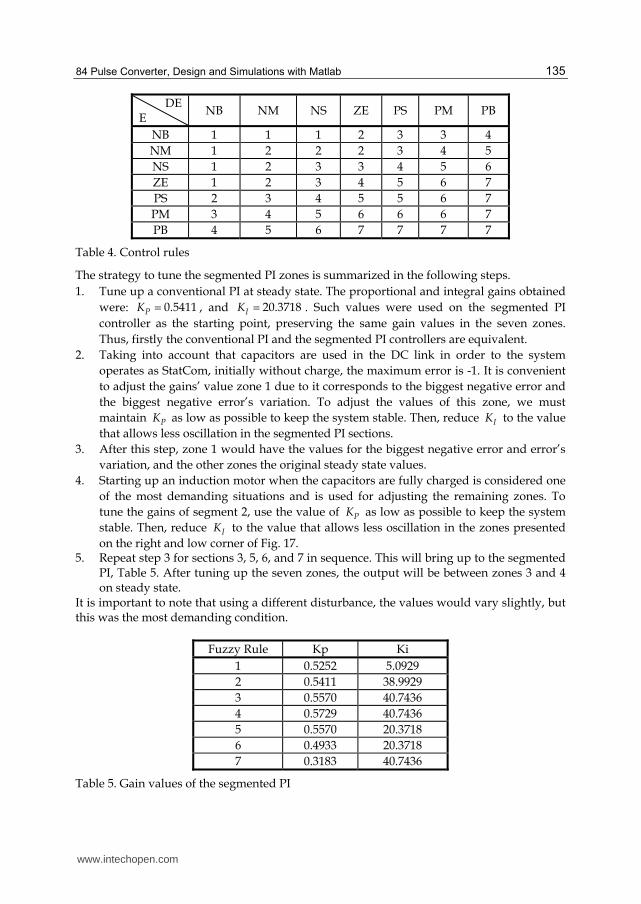
Table 4. Control rules
The strategy to tune the segmented PI zones is summarized in the following steps.
1. Tune up a conventional PI at steady state. The proportional and integral gains obtained
were: 0.5411PK , and 20.3718IK . Such values were used on the segmented PI
controller as the starting point, preserving the same gain values in the seven zones.
Thus, firstly the conventional PI and the segmented PI controllers are equivalent.
2. Taking into account that capacitors are used in the DC link in order to the system
operates as StatCom, initially without charge, the maximum error is -1. It is convenient
to adjust the gains’ value zone 1 due to it corresponds to the biggest negative error and
the biggest negative error’s variation. To adjust the values of this zone, we must
maintain PK as low as possible to keep the system stable. Then, reduce IK to the value
that allows less oscillation in the segmented PI sections.
3. After this step, zone 1 would have the values for the biggest negative error and error’s
variation, and the other zones the original steady state values.
4. Starting up an induction motor when the capacitors are fully charged is considered one
of the most demanding situations and is used for adjusting the remaining zones. To
tune the gains of segment 2, use the value of PK as low as possible to keep the system
stable. Then, reduce IK to the value that allows less oscillation in the zones presented
on the right and low corner of Fig. 17. 5. Repeat step 3 for sections 3, 5, 6, and 7 in sequence. This will bring up to the segmented
PI, Table 5. After tuning up the seven zones, the output will be between zones 3 and 4 on steady state.
It is important to note that using a different disturbance, the values would vary slightly, but this was the most demanding condition.
Fuzzy Rule Kp Ki
1 0.5252 5.0929
2 0.5411 38.9929
3 0.5570 40.7436
4 0.5729 40.7436
5 0.5570 20.3718
6 0.4933 20.3718
7 0.3183 40.7436
Table 5. Gain values of the segmented PI
www.intechopen.com

Applications of MATLAB in Science and Engineering
136
3.2 Simulation results
The StatCom model and the segmented PI controller with the values obtained from the previous section were simulated in Matlab/Simulink, using Piece-wise Linear Electrical Circuit Simulation (PLECS). PLECS was used because it is a fast simulation toolbox for electrical circuits within the Simulink environment specially designed for power electronics systems. It is also a powerful tool for any combined simulation of electrical circuits and controls (http://www.plexim.com, 2010) . The PLL-block feeds the two six-pulse generators at the fundamental frequency and it is used to bring forth the seven level pulses at six times the fundamental frequency to have them synchronized to the system and configured as the
84-pulse StatCom. The signal calculated from the segmented PI controller is utilized to
lag or lead the StatCom voltage with respect to the system. While the phase-angle lags the
bus voltage ( < 0), energy is flowing to the DC capacitor, charging it and doing the
StatCom draws capacitive current. Contrarily, inductive current is drawn while ( > 0)
(Aredes & Santos Jr., 2000). The figures 14 to 16 illustrate the system behavior when short-duration root-mean-square (rms) problems (IEEE Std 1159, 2009) are presented. A Sag or dip is a reduction of AC voltage at a given frequency lasting from 0.5 cycles to 30 cycles and magnitudes between 0.1 to 0.9 pu, it is usually caused by system faults, and is often the result of switching on loads with heavy startup currents (Seymour & Horsley, 2005; IEEE Std 1159, 2009). Fig. 14 exhibits the system behavior when a Sag of 6 cycles and 0.3 pu appears on the system. Using a conventional PI controlled StatCom the error has several oscillations as presented in Fig. 14a; Fig. 14b is the error when a segmented PI controlled StatCom is employed. The smoother and faster behavior of this new controller
Segmented PI controllerConventional PI controller
b)a)
d)c)
Fig. 14. Sag 0.3 PU
www.intechopen.com

84 Pulse Converter, Design and Simulations with Matlab
137
becomes visible. Figs. 14c-d are included to illustrate the rules corresponding to each error and error’s increment. Rules 3 and 4 on Table 5 indicate that integral gains are the same for both regions, and proportional gains vary slightly, so, having the segmented PI controller switching among these two zones would bring the system to a good performance. The conventional PI controller used the original values and this is presented as rule number 4, which was the starting point for calculating the segmented PI gains. Contrarily to a Sag, a Swell represents an increase in the AC voltage, lasting from 0.5 cycles to 30 cycles and magnitudes between 1.1 to 1.8 pu. Swells commonly arise due to high-impedance neutral connections, sudden (especially large) load reductions, and a single-phase fault on a three-phase system (Seymour & Horsley, 2005; IEEE Std 1159, 2009). Fig 15 illustrates the system under a swell of 6 cycles and 0.3 pu. It can be noticed that Fig 15a presents more oscillation than Fig. 15b. Also the steady state is reached faster using the segmented PI controlled StatCom. Again, Figs. 15c-d are included to illustrate the rules corresponding to each error and the error’s increment, using original values in rule number 4 for the conventional PI controller, and switching between rules 3 and 4 for the segmented PI controller, which is the behavior needed.
b)a)
d)
Segmented PI controller
c)
Conventional PI controller
Fig. 15. Swell 0.3 PU
An interruption is one of the most demanding problems presented at the source nodes, and occurs when the supply voltage or load current decreases to less than 0.1 pu for a period of time not exceeding 1 min. Interruptions can be the result of power system faults, equipment
www.intechopen.com
Applications of MATLAB in Science and Engineering
138
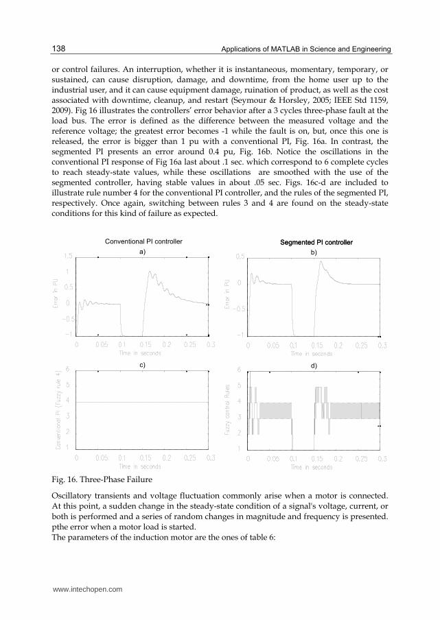
or control failures. An interruption, whether it is instantaneous, momentary, temporary, or sustained, can cause disruption, damage, and downtime, from the home user up to the industrial user, and it can cause equipment damage, ruination of product, as well as the cost associated with downtime, cleanup, and restart (Seymour & Horsley, 2005; IEEE Std 1159, 2009). Fig 16 illustrates the controllers’ error behavior after a 3 cycles three-phase fault at the load bus. The error is defined as the difference between the measured voltage and the reference voltage; the greatest error becomes -1 while the fault is on, but, once this one is released, the error is bigger than 1 pu with a conventional PI, Fig. 16a. In contrast, the segmented PI presents an error around 0.4 pu, Fig. 16b. Notice the oscillations in the conventional PI response of Fig 16a last about .1 sec. which correspond to 6 complete cycles to reach steady-state values, while these oscillations are smoothed with the use of the segmented controller, having stable values in about .05 sec. Figs. 16c-d are included to illustrate rule number 4 for the conventional PI controller, and the rules of the segmented PI, respectively. Once again, switching between rules 3 and 4 are found on the steady-state conditions for this kind of failure as expected.
Segmented PI controller
b)a)
d)
Segmented PI controller
c)
Conventional PI controller
Fig. 16. Three-Phase Failure
Oscillatory transients and voltage fluctuation commonly arise when a motor is connected.
At this point, a sudden change in the steady-state condition of a signal's voltage, current, or
both is performed and a series of random changes in magnitude and frequency is presented.
pthe error when a motor load is started.
The parameters of the induction motor are the ones of table 6:
www.intechopen.com

84 Pulse Converter, Design and Simulations with Matlab
139
Motor parameter Value
Nominal Power 2250HP (2300V)
Rs 0.029 Ohms
Lls 0.0006 Henries
Rr .022 Ohms
Llr 0.0006 Henries
Lm 0.0346 Henries
J 6.5107 Joules
Table 6. Motor parameters used on motor startup simulation
The error for the conventional PI has several big oscillations, Fig. 17a, while the segmented one exhibits very fast response to reach the steady state, and minimum oscillation, Fig. 17b. Figs. 17 c-d are also included to illustrate the rule number 4 (conventional PI controller), and the rules of the segmented PI, respectively.
b)a)
d)
Segmented PI controller
c)
Conventional PI controller
Fig. 17. Motor Start up
With these simulations it is demonstrated that when the system is stressed, the segmented
PI controller exhibits a quite appropriate response.
www.intechopen.com

Applications of MATLAB in Science and Engineering
140
4. Conclusion
This chapter presents a study about one of the most used VSC-based FACTS devices: the StatCom. A novel strategy to generate higher pulse number by combining one twelve-pulse converter with a seven level converter, in order to attain the overall 84-pulses VSC performance with the corresponding high quality voltage wave, has been presented. The associated seven level converter is built through the combination of two three level topologies with asymmetric gate pattern inverters. The explanation of the control stages is described. Through simulations, the suitability of the proposal is demonstrated. The reinjection principle, mainly applicable with Total Harmonic Distortion reduction purposes, has been demonstrated utilizing the harmonics’ calculation. With this low THD, the inverter is able to be used in special applications. The proposition allows savings in the total amount of employed switches along with a small quantity of capacitors to prevent problems of unbalancing. The segmented PI controller introduced, gives a fast and appropriate response when used for connecting the StatCom to the system on common but stressful situations. Two of the most common failures on the system have been addressed (Sag and Swell) having performance similar to conventional PI controllers. Three phase failure releases are some of the biggest problems to solve due to high peaks received on the loads; this problem is significantly reduced with the use of segmented PI controller. Induction motor startup is one of the most demanding situations for the power system, and the use of a segmented PI controller had demonstrated a very fast response to bring the motor to steady-state condition.
5. References
ABB Power Systems AB, “ABB STATCOM For flexibility in power systems”, Västerås, A02-0165E
Acha, E., Fuerte-Esquivel, C. R., Ambriz, H., Angeles, C.: FACTS. Modelling and Simulation in Power Networks. (John Wiley and Sons, LTD, 2004.)
Aredes, M., Santos Jr., G.: “A Robust Control for Multipulse StatComs,” Proceedings of IPEC 2000, Vol. 4, pp. 2163 - 2168, Tokyo, 2000.
Blazic, B.; Papic, I.; “Improved D-StatCom control for operation with unbalanced currents and voltages”, IEEE Transactions on Power Delivery, Volume: 21 , Issue: 1 2006 , pp 225 – 233
Cavaliere, C.A.C.; Watanabe, E.H.; Aredes, M.; “Multi-pulse STATCOM operation under unbalanced voltages “,IEEE Power Engineering Society Winter Meeting, 2002. Volume: 1, 2002 , pp 567 – 572
CIGRE, ”Static Synchronous Compensator”, working group 14.19, September 1998. Davalos-Marin, R.: ‘Detailed Analysis of a multi-pulse StatCom’, Cinvestav – Internal
Report. May 2003, http://www.dispositivosfacts.com.mx/dir_tesis_doc.html El-Moursi, M. S.; Sharaf, A. M. “Novel Controllers for the 48-Pulse VSC StatCom and SSSC
for Voltage Regulation and Reactive Power Compensation”, IEEE Transactions on Power Systems, Vol. 20, No. 4, November 2005, pp. 1985-1997
www.intechopen.com

84 Pulse Converter, Design and Simulations with Matlab
141
Han, B., Choo, W., Choi, J., Park, Y., Cho, Y.: “New Configuration of 36-Pulse Voltage source Converter Using Pulse-Interleaving Circuit”, Proceedings of the Eight International Conference on Electrical Machines and Systems 2005, September 27-29, 2005
Hingorani, N.G.; , "FACTS Technology - State of the Art, Current Challenges and the Future Prospects," Power Engineering Society General Meeting, 2007. IEEE , vol., no., pp.1-4, 24-28 June 2007
Hingorani, N. G., and Gyugyi, L.: ‘Understanding FACTS,’ (IEEE Press 2000). Hochgraf, C.; Lasseter, R.H.: “Statcom controls for operation with unbalanced voltages”,
IEEE Transactions on Power Delivery, Volume: 13 , Issue: 2, 1998 , pp 538 – 544 IEEE Std 519-1992: IEEE Recommended Practices and Requirements for Harmonic Control
in Electrical Power Systems, 1992. Jin-Ho Cho, Eui-Ho Song, “Stationary Reference Frame-Based Simple Active Power Filter
with Voltage Regulation”, Industrial Electronics, 2001. Proceedings. ISIE 2001. IEEE International Symposium on, Vol. 3, June 2001, pp. 2044-2048
Krause, P. C., Wasynczuk, O., and Sud, S. D.: ‘Analysis of Electric Machinery an Drive Systems, Second Edition,’ (IEEE Series on Power Engineering, pp. 487, 2002)
Kuang Li; Jinjun Liu; Zhaoan Wang; Biao Wei; “Strategies and Operating Point Optimization of STATCOM Control for Voltage Unbalance Mitigation in Three-Phase Three-Wire Systems “, IEEE Transactions on Power Delivery, Volume: 22 , Issue: 1, 2007 , pp 413 – 422
Liu, Y. H., Arrillaga, J., Watson, N. R.: “A New STATCOM Configuration Using Multi-Level DC Voltage Reinjection for High Power Application”, IEEE Transactions on Power Delivery, Vol. 19, No. 4, October 2004, pp. 1828-1834.
Liu, Y. H.; Perera, L. B.; Arrillaga J. and Watson, N. R. “Harmonic Reduction in the Double Bridge Parallel Converter by Multi-Level DC-Voltage Reinjection”, 2004 lntenational Conference on Power System Technology POWERCON 2004, 21-24 November 2004
Liu, Y. H.; Watson, N. R.; Arrillaga, J. “A New Concept for the Control of the Harmonic Content of Voltage Source Converters”, The Fifth International Conference on Power Electronics and Drive Systems, 2003, 17-20 Nov. 2003, pp. 793- 798 Vol.1
Norouzi, Amir H.; Shard, A.M. “A Novel Control Scheme for the STATCOM Stability Enhancement”, 2003 IEEE PES Transmission and Distribution Conference and Exposition, Sept. 2003
Pal, A. K., Mudi, R. K.” Self-Tuning Fuzzy PI Controller and its Application to HVAC Systems”, International Journal of Computational Cognition, vol.6, no.1, March 2008, pages 25-30.
Pan, W., Xu, Z., Zhang, J.: “Novel configuration of 60-pulse voltage source converter for StatCom application,” International Journal of Emerging Electric Power Systems, Vol 8, Issue 5, 2007, Article 7.
Piece-wise Linear Electrical Circuit Simulation, User Manual Version 3.0, http://www.plexim.com, accessed on February 2010
Samir Ahmad Mussa, Hari Bruno Mohr, “Three-phase Digital PLL for Synchronizing on Three-Phase/Switch/Level Boost Rectifier by DSP”, 35th Annual IEEE Power Electronics Specialists Conference Aachen, Germany, 2004, pp. 3659-366
Seymour, Joseph; Horsley,Terry; “The Seven Types of Power Problems”, White paper # 18, APC Legendary Reliability, 2005 American Power Conversion
www.intechopen.com

Applications of MATLAB in Science and Engineering
142
Song, Yong Hua; Johns, Allan T. “Flexible AC transmission systems FACTS”, IEE Power and Energy Series 30, 1999.
Voraphonpiput, N.; Chatratana, S. “Analysis of Quasi 24-Pulse StatCom Operation and Control Using ATP-EMTP”, TENCON 2004. 2004 IEEE Region 10 Conference, Nov. 2004 Vol. 3, pp. 359- 362
Wang, H. F.: Applications of damping torque analysis to StatCom control, Electrical Power and Energy Systems, Vol. 22, 2000, pp. 197-204.
www.intechopen.com

Applications of MATLAB in Science and EngineeringEdited by Prof. Tadeusz Michalowski
ISBN 978-953-307-708-6Hard cover, 510 pagesPublisher InTechPublished online 09, September, 2011Published in print edition September, 2011
InTech EuropeUniversity Campus STeP Ri Slavka Krautzeka 83/A 51000 Rijeka, Croatia Phone: +385 (51) 770 447 Fax: +385 (51) 686 166www.intechopen.com
InTech ChinaUnit 405, Office Block, Hotel Equatorial Shanghai No.65, Yan An Road (West), Shanghai, 200040, China
Phone: +86-21-62489820 Fax: +86-21-62489821
The book consists of 24 chapters illustrating a wide range of areas where MATLAB tools are applied. Theseareas include mathematics, physics, chemistry and chemical engineering, mechanical engineering, biological(molecular biology) and medical sciences, communication and control systems, digital signal, image and videoprocessing, system modeling and simulation. Many interesting problems have been included throughout thebook, and its contents will be beneficial for students and professionals in wide areas of interest.
How to referenceIn order to correctly reference this scholarly work, feel free to copy and paste the following:
Antonio Valderra ́bano Gonza ́lez, Juan Manuel Ramirez and Francisco Beltra ́n Carbajal (2011). 84 PulseConverter, Design and Simulations with Matlab, Applications of MATLAB in Science and Engineering, Prof.Tadeusz Michalowski (Ed.), ISBN: 978-953-307-708-6, InTech, Available from:http://www.intechopen.com/books/applications-of-matlab-in-science-and-engineering/84-pulse-converter-design-and-simulations-with-matlab

© 2011 The Author(s). Licensee IntechOpen. This chapter is distributedunder the terms of the Creative Commons Attribution-NonCommercial-ShareAlike-3.0 License, which permits use, distribution and reproduction fornon-commercial purposes, provided the original is properly cited andderivative works building on this content are distributed under the samelicense.