815-3012, 815-3024 sine wave inverter/chargers · installation guide for information. † do not...
TRANSCRIPT

TM
TM
Freedom SWSine Wave Inverter/Chargers
Owner’s Guide
FREEDOM SW 3012
FREEDOM SW 3012
FREEDOM SW 3012
FREEDOM SW 3012CLEAR FAULTRESET INVERTER
ENABLE
INVERTERENABLED
AC IN
FAULT
GENSUPPORT CHARGINGWARNING
CLEAR FAULT
RESET
INVERTER
ENABLE
INVERTER
ENABLED
AC IN
FAULT
GEN
SUPPORT
CHARGINGWARNING
Freedom SW 3012 shown.
Model Numbers815-3012, 815-3024815-2012, 815-2024
™
FSW Owners Guide.book Page i Tuesday, August 7, 2018 9:03 AM

FSW Owners Guide.book Page ii Tuesday, August 7, 2018 9:03 AM

97-0019-01-01 i
Copyright © 2014-2018 Schneider Electric. All Rights Reserved. All trademarks are owned by Schneider Electric Industries SAS or its affiliated companies.
Exclusion for DocumentationUNLESS SPECIFICALLY AGREED TO IN WRITING, SELLER(A) MAKES NO WARRANTY AS TO THE ACCURACY, SUFFICIENCY OR SUITABILITY OF ANY TECHNICAL OR OTHER INFORMATION PROVIDED IN ITS MANUALS OR OTHER DOCUMENTATION;(B) ASSUMES NO RESPONSIBILITY OR LIABILITY FOR LOSSES, DAMAGES, COSTS OR EXPENSES, WHETHER SPECIAL, DIRECT, INDIRECT, CONSEQUENTIAL OR INCIDENTAL, WHICH MIGHT ARISE OUT OF THE USE OF SUCH INFORMATION. THE USE OF ANY SUCH INFORMATION WILL BE ENTIRELY AT THE USER’S RISK; AND(C) REMINDS YOU THAT IF THIS MANUAL IS IN ANY LANGUAGE OTHER THAN ENGLISH, ALTHOUGH STEPS HAVE BEEN TAKEN TO MAINTAIN THE ACCURACY OF THE TRANSLATION, THE ACCURACY CANNOT BE GUARANTEED. APPROVED CONTENT IS CONTAINED WITH THE ENGLISH LANGUAGE VERSION WHICH IS POSTED AT WWW.XANTREX.COM.
Document Part Number97-0019-01-01
Date and RevisionAug 2018 Rev G
Product Numbers815-2012 (Freedom SW 2012), 815-2024 (Freedom SW 2024)815-3012 (Freedom SW 3012), 815-3024 (Freedom SW 3024)
Contact Information
Information About Your SystemAs soon as you open your product, record the following information and be sure to keep your proof of purchase.
To view, download, or print the latest revision, visit the website shown under Contact Information.
Telephone: 1 800 670 0707 (toll free North America)1 408 987 6030 (direct)
Web: www.xantrex.com
Serial Number _________________________________
Product Number _________________________________
Purchased From _________________________________
Purchase Date _________________________________
FSW Owners Guide.book Page i Tuesday, August 7, 2018 9:03 AM

ii Freedom SW Owner’s Guide
About This Guide
PurposeThe purpose of this Owner’s Guide is to provide explanations and procedures for operating, troubleshooting, and maintaining the Freedom SW Inverter/Charger.
ScopeThe Guide provides safety and operating guidelines as well as information on configuring the inverter/charger. It also provides information about troubleshooting the unit. It does not provide details about particular brands of batteries. You need to consult individual battery manufacturers for this information.
AudienceThe Guide is intended for users and operators of the Freedom SW Inverter/Charger.
Related InformationYou can find more information about Xantrex-branded products and services at www.xantrex.com.For information on product installation, please refer to the Freedom SW Installation Guide (Document Part Number: 97-0020-01-01).NOTE: The Installation Guide is primarily intended for qualified personnel who need to install and configure the Freedom SW Inverter/Charger. Qualified personnel have training, knowledge, and experience in:• Installing electrical equipment and PV power systems (up to 1000
volts).• Applying all applicable installation codes.• Analyzing and reducing the hazards involved in performing electrical
work.• Selecting and using Personal Protective Equipment (PPE).
FSW Owners Guide.book Page ii Tuesday, August 7, 2018 9:03 AM

97-0019-01-01 iii
Important Safety Instructions
IMPORTANT: READ AND SAVE THIS OWNER’S GUIDE FOR FUTURE REFERENCE.
This chapter contains important safety and installation instructions for the Freedom SW Inverter/Charger (Freedom SW). Each time, before using the Freedom SW, READ ALL instructions and cautionary markings on or provided with the inverter/charger, the batteries, and all appropriate sections of this guide.NOTE: The Freedom SW contains no user-serviceable parts.The following special messages may appear throughout this bulletin or on the equipment to warn of potential hazards or to call attention to information that clarifies or simplifies a procedure.
The addition of either symbol to a “Danger” or “Warning” safetylabel indicates that an electrical hazard exists which will result inpersonal injury if the instructions are not followed.
This is the safety alert symbol. It is used to alert you to potentialpersonal injury hazards. Obey all safety messages that follow thissymbol to avoid possible injury or death.
DANGER indicates an imminently hazardous situation, which, if notavoided, will result in death or serious injury.
WARNING indicates a potentially hazardous situation, which, if notavoided, can result in death or serious injury.
CAUTION indicates a potentially hazardous situation, which, if notavoided, can result in moderate or minor injury.
NOTICE indicates a potentially hazardous situation, which, if not avoided,can result in equipment damage.
IMPORTANT: These notes describe things which are important for you toknow, however, they are not as serious as a caution or warning.
FSW Owners Guide.book Page iii Tuesday, August 7, 2018 9:03 AM

iv Freedom SW Owner’s Guide
Safety Information
ELECTRICAL SHOCK HAZARD• Do not expose the Freedom SW to rain, snow, spray, or bilge water.
This inverter/charger is designed for marine applications only whenadditional drip protection is installed in certain orientations. See theinstallation guide for information.
• Do not operate the inverter/charger if it has received a sharp blow,been dropped, has cracks or openings in the enclosure including ifthe AC terminal cover has been lost, damaged, or will not close, orotherwise damaged in any other way.
• Do not disassemble the inverter/charger. Internal capacitors remaincharged after all power is disconnected.
• Disconnect both AC and DC power from the inverter/charger beforeattempting any maintenance or cleaning or working on any circuitsconnected to the inverter/charger. The INVERTER ENABLE buttonon the front panel does not function like a power switch thatenergizes or de-energizes the unit arbitrarily. When AC and DC powersources are connected and present, the unit is always energized.
• Do not operate the inverter/charger with damaged or substandardwiring. Make sure that all wiring is in good condition and is notundersized.
Failure to follow these instructions will result in death or serious injury.
FIRE AND BURN HAZARD• Do not cover or obstruct the air intake vent openings and/or install in
a zero-clearance compartment.• Do not use transformerless battery chargers in conjunction with the
inverter/charger due to overheating.
Failure to follow these instructions will result in death or serious injury.
EXPLOSION HAZARD• Charge only properly rated (such as 12 V) lead-acid (GEL, AGM,
Flooded, or lead-calcium) rechargeable batteries because otherbattery types may explode.
• Do not work in the vicinity of lead-acid batteries. Batteries generateexplosive gases during normal operation. See note #1.
• Do not install and/or operate in compartments containing flammablematerials or in locations that require ignition-protected equipment.See notes #2 and #3.
• When using Lithium-Ion batteries, ensure that the battery pack beingused includes a certified Battery Management System (BMS) withsafety controls.
Failure to follow these instructions will result in death or serious injury.
FSW Owners Guide.book Page iv Tuesday, August 7, 2018 9:03 AM
97-0019-01-01 v
NOTES:1. Follow these instructions and those published by the battery
manufacturer and the manufacturer of any equipment you intend to use in the vicinity of the battery. Review cautionary markings on these products and on the engine.
2. This inverter/charger contains components which tend to produce arcs or sparks.
3. Locations include any space containing gasoline-powered machinery, fuel tanks, as well as joints, fittings, or other connections between components of the fuel system.
Precautions When Working With Batteries
NOTES:1. Mount and place the Freedom SW Inverter/Charger unit away from
batteries in a well ventilated compartment.
2. Always have someone within range of your voice or close enough to come to your aid when you work near a lead-acid battery.
3. Always have plenty of fresh water and soap nearby in case battery acid contacts skin, clothing, or eyes.
4. If battery acid contacts skin or clothing, wash immediately with soap and water. If acid enters your eye, immediately flood it with running cold water for at least twenty minutes and get medical attention immediately.
5. Use extra caution to reduce the risk or dropping a metal tool on the battery. It could spark or short circuit the battery or other electrical parts and could cause an explosion.
6. Batteries can produce a short circuit current high enough to weld a ring or metal bracelet or the like to the battery terminal, causing a severe burn.
7. When removing a battery, always remove the negative terminal from the battery first for systems with grounded negative. If it is grounded positive, remove the positive terminal first. Make sure all loads connected to the battery and all accessories are off so you don’t cause an arc.
BURN FROM HIGH SHORT-CIRCUIT CURRENT, FIRE AND EXPLOSION FROM VENTED GASES HAZARDS
• Always wear proper, non-absorbent gloves, complete eye protection,and clothing protection. Avoid touching your eyes and wiping yourforehead while working near batteries. See note #4.
• Remove all personal metal items, like rings, bracelets, and watcheswhen working with batteries. See notes #5 and #6 below.
• Never smoke or allow a spark or flame near the engine or batteries.• Never charge a frozen battery.
Failure to follow these instructions can result in death or serious injury.
FSW Owners Guide.book Page v Tuesday, August 7, 2018 9:03 AM
vi Freedom SW Owner’s Guide
Precautions When Preparing to Charge
NOTES:• Study and follow all of the battery manufacturer's specific precautions,
such as removing or not removing cell caps while charging, whether equalization is acceptable for your battery, and recommended rates of charge.
• For flooded non-sealed batteries, add distilled water in each cell until battery acid reaches the level specified by the battery manufacturer. This helps to purge excessive gas from cells. Do not overfill. For a battery without removable cell caps, carefully follow manufacturer's instructions.
Precautions When Placing the Inverter/Charger
EXPOSURE TO CHEMICALS AND GASES HAZARD• Make sure the area around the battery is well ventilated.• Make sure the voltage of the batteries matches the output voltage of
the inverter/charger.• Be careful to keep corrosion from coming into contact with your eyes
and skin when cleaning battery terminals.
Failure to follow these instructions can result in death or serious injury.
RISK OF DAMAGE TO THE INVERTER/CHARGER• Never allow battery acid to drip on the inverter/charger when reading
gravity, or filling battery.• Never place the Freedom SW Inverter/Charger unit directly above
batteries; gases from a battery will corrode and damage the inverter/charger.
• Do not place a battery on top of the inverter/charger.
Failure to follow these instructions can damage the unit and/or damageother equipment.
FSW Owners Guide.book Page vi Tuesday, August 7, 2018 9:03 AM

97-0019-01-01 vii
RegulatoryThe Freedom SW Inverter/Charger is certified to appropriate US and Canadian standards. For more information see “Regulatory Approvals” on the Specifications section in the Owner’s Guide.The Freedom SW Inverter/Charger is intended to be used for mobile or commercial applications. This inverter/charger is designed for marine applications only when additional drip protection is installed in certain orientations. It is not intended for other applications as it may not comply with the additional safety code requirements needed for those other applications. See “Limitations On Use” below.
FCC Information to the UserThis equipment has been tested and found to comply with the limits for a Class B digital device, pursuant to part 15 of the FCC Rules. These limits are designed to provide reasonable protection against harmful interference in a residential installation. This equipment generates, uses, and can radiate radio frequency energy and, if not installed and used in accordance with the instructions, may cause harmful interference to radio communications.However, there is no guarantee that interference will not occur in a particular installation. If this equipment does cause harmful interference to radio or television reception, which can be determined by turning the equipment off and on, the user is encouraged to try to correct the interference by one or more of the following measures:• Reorient or relocate the receiving antenna.• Increase the separation between the equipment and receiver.• Connect the equipment into an outlet on a circuit different from that to
which the receiver is connected.• Consult the dealer or an experienced radio/TV technician for help.
LIMITATIONS ON USEDo not use in connection with life support systems or other medicalequipment or devices.
Failure to follow these instructions can result in death or serious injury.
Unauthorized changes or modifications to the equipment could void theuser’s authority to operate the equipment.
FSW Owners Guide.book Page vii Tuesday, August 7, 2018 9:03 AM

viii Freedom SW Owner’s Guide
End of Life DisposalThe Freedom SW is designed with environmental awareness and sustainability in mind. At the end of its useful life, the Freedom SW can be decommissioned and disassembled. Components which can be recycled must be recycled and those that cannot be recycled must be disposed of according to local, regional, or national environmental regulations.Many of the electrical components used in the Freedom SW are made of recyclable material like steel, copper, aluminum, and other alloys. These materials can be auctioned off to traditional scrap metal recycling companies who resell reusable scraps.Electronic equipment such as the circuit boards, connectors, and fuses can be broken down and recycled by specialized recycling companies whose goal is to avoid having these components end up in the landfill.For more information on disposal, contact Xantrex.
FSW Owners Guide.book Page viii Tuesday, August 7, 2018 9:03 AM

Important Safety Instructions . . . . . . . . . . . . . . . . . . . . . . . . . . . . . . . . . . . . . . . . . . . . . . . . . . . . . . . . . . . . . . . . . . . . . . . . . . . . . . . . . . . . iii
Introduction . . . . . . . . . . . . . . . . . . . . . . . . . . . . . . . . . . . . . . . . . . . . . . . . . . . . . . . . . . . . . . . . . . . . . . . . . . . . . . . . . . . . . . . . . . . . . . . . . . . .1Materials List . . . . . . . . . . . . . . . . . . . . . . . . . . . . . . . . . . . . . . . . . . . . . . . . . . . . . . . . . . . . . . . . . . . . . . . . . . . . . . . . . . . . . . . . . . .2Key Features . . . . . . . . . . . . . . . . . . . . . . . . . . . . . . . . . . . . . . . . . . . . . . . . . . . . . . . . . . . . . . . . . . . . . . . . . . . . . . . . . . . . . . . . . . .3
Key Features Explained . . . . . . . . . . . . . . . . . . . . . . . . . . . . . . . . . . . . . . . . . . . . . . . . . . . . . . . . . . . . . . . . . . . . . . . . . . . . . . .4Stacking . . . . . . . . . . . . . . . . . . . . . . . . . . . . . . . . . . . . . . . . . . . . . . . . . . . . . . . . . . . . . . . . . . . . . . . . . . . . . . . . . . . . . . . . . . .5Stack Charging . . . . . . . . . . . . . . . . . . . . . . . . . . . . . . . . . . . . . . . . . . . . . . . . . . . . . . . . . . . . . . . . . . . . . . . . . . . . . . . . . . . . . .5Generator Assist . . . . . . . . . . . . . . . . . . . . . . . . . . . . . . . . . . . . . . . . . . . . . . . . . . . . . . . . . . . . . . . . . . . . . . . . . . . . . . . . . . . . .6
Basic Protection Features . . . . . . . . . . . . . . . . . . . . . . . . . . . . . . . . . . . . . . . . . . . . . . . . . . . . . . . . . . . . . . . . . . . . . . . . . . . . . . . . . .6System Components . . . . . . . . . . . . . . . . . . . . . . . . . . . . . . . . . . . . . . . . . . . . . . . . . . . . . . . . . . . . . . . . . . . . . . . . . . . . . . . . . . . . . . . . . . . . .7
Xanbus System . . . . . . . . . . . . . . . . . . . . . . . . . . . . . . . . . . . . . . . . . . . . . . . . . . . . . . . . . . . . . . . . . . . . . . . . . . . . . . . . . . . . . . . . . .7Xanbus-enabled Products and Accessories . . . . . . . . . . . . . . . . . . . . . . . . . . . . . . . . . . . . . . . . . . . . . . . . . . . . . . . . . . . . . . . . . . . .9
Freedom SW Inverter/Charger Mechanical Features . . . . . . . . . . . . . . . . . . . . . . . . . . . . . . . . . . . . . . . . . . . . . . . . . . . . . . . . . . . . . . . . . . .10Freedom SW Front and Side Panels . . . . . . . . . . . . . . . . . . . . . . . . . . . . . . . . . . . . . . . . . . . . . . . . . . . . . . . . . . . . . . . . . . . . . . . .11Freedom SW AC and DC Side Panels . . . . . . . . . . . . . . . . . . . . . . . . . . . . . . . . . . . . . . . . . . . . . . . . . . . . . . . . . . . . . . . . . . . . . . .14Freedom SW Supplied Accessories . . . . . . . . . . . . . . . . . . . . . . . . . . . . . . . . . . . . . . . . . . . . . . . . . . . . . . . . . . . . . . . . . . . . . . . . .15
Freedom Inverter/Charger Operation . . . . . . . . . . . . . . . . . . . . . . . . . . . . . . . . . . . . . . . . . . . . . . . . . . . . . . . . . . . . . . . . . . . . . . . . . . . . . . .17Start Up Behavior . . . . . . . . . . . . . . . . . . . . . . . . . . . . . . . . . . . . . . . . . . . . . . . . . . . . . . . . . . . . . . . . . . . . . . . . . . . . . . . . . . . . . .17Inverter Operation Using the Front Panel . . . . . . . . . . . . . . . . . . . . . . . . . . . . . . . . . . . . . . . . . . . . . . . . . . . . . . . . . . . . . . . . . . . .18
Operating Limits for Inverter Operation . . . . . . . . . . . . . . . . . . . . . . . . . . . . . . . . . . . . . . . . . . . . . . . . . . . . . . . . . . . . . . . . . .20Operating Limits for Charger Operation . . . . . . . . . . . . . . . . . . . . . . . . . . . . . . . . . . . . . . . . . . . . . . . . . . . . . . . . . . . . . . . . .21
Contents
FSW Owners Guide.book Page i Tuesday, August 7, 2018 9:03 AM

Operating the Freedom SW with the SCP. . . . . . . . . . . . . . . . . . . . . . . . . . . . . . . . . . . . . . . . . . . . . . . . . . . . . . . . . . . . . . . . . . . . . . . . . . . .23Using the Xanbus SCP . . . . . . . . . . . . . . . . . . . . . . . . . . . . . . . . . . . . . . . . . . . . . . . . . . . . . . . . . . . . . . . . . . . . . . . . . . . . . . . . . . .24
System Control Panel . . . . . . . . . . . . . . . . . . . . . . . . . . . . . . . . . . . . . . . . . . . . . . . . . . . . . . . . . . . . . . . . . . . . . . . . . . . . . . . .24SCP Navigation . . . . . . . . . . . . . . . . . . . . . . . . . . . . . . . . . . . . . . . . . . . . . . . . . . . . . . . . . . . . . . . . . . . . . . . . . . . . . . . . . . . . . . . .27
Startup Screen . . . . . . . . . . . . . . . . . . . . . . . . . . . . . . . . . . . . . . . . . . . . . . . . . . . . . . . . . . . . . . . . . . . . . . . . . . . . . . . . . . . . . .27Viewing the SCP Home Screens . . . . . . . . . . . . . . . . . . . . . . . . . . . . . . . . . . . . . . . . . . . . . . . . . . . . . . . . . . . . . . . . . . . . . . .27Soft Key Navigation . . . . . . . . . . . . . . . . . . . . . . . . . . . . . . . . . . . . . . . . . . . . . . . . . . . . . . . . . . . . . . . . . . . . . . . . . . . . . . . . .29
Viewing the Firmware Revision Number . . . . . . . . . . . . . . . . . . . . . . . . . . . . . . . . . . . . . . . . . . . . . . . . . . . . . . . . . . . . . . . . . . . .31Setting the Time and Date . . . . . . . . . . . . . . . . . . . . . . . . . . . . . . . . . . . . . . . . . . . . . . . . . . . . . . . . . . . . . . . . . . . . . . . . . . . . . . . .32Using the STBY/ON Fault Clear Button . . . . . . . . . . . . . . . . . . . . . . . . . . . . . . . . . . . . . . . . . . . . . . . . . . . . . . . . . . . . . . . . . . . . .32Reading the System Status Screen . . . . . . . . . . . . . . . . . . . . . . . . . . . . . . . . . . . . . . . . . . . . . . . . . . . . . . . . . . . . . . . . . . . . . . . . . .33Reading the Freedom SW Device Setup Screen . . . . . . . . . . . . . . . . . . . . . . . . . . . . . . . . . . . . . . . . . . . . . . . . . . . . . . . . . . . . . . .35
Configuring the Freedom SW using the SCP . . . . . . . . . . . . . . . . . . . . . . . . . . . . . . . . . . . . . . . . . . . . . . . . . . . . . . . . . . . . . . . . . . . . . . . . .39System Menu Map . . . . . . . . . . . . . . . . . . . . . . . . . . . . . . . . . . . . . . . . . . . . . . . . . . . . . . . . . . . . . . . . . . . . . . . . . . . . . . . . . . . . . .39
Viewing the System Status Screen . . . . . . . . . . . . . . . . . . . . . . . . . . . . . . . . . . . . . . . . . . . . . . . . . . . . . . . . . . . . . . . . . . . . . .40Viewing the Select Device Menu . . . . . . . . . . . . . . . . . . . . . . . . . . . . . . . . . . . . . . . . . . . . . . . . . . . . . . . . . . . . . . . . . . . . . . .40Selecting the Freedom SW from the Select Device Menu . . . . . . . . . . . . . . . . . . . . . . . . . . . . . . . . . . . . . . . . . . . . . . . . . . . .41
Changing Configurable Settings From The Device Setup Menu Screen . . . . . . . . . . . . . . . . . . . . . . . . . . . . . . . . . . . . . . . . . . . .42Using Search Mode . . . . . . . . . . . . . . . . . . . . . . . . . . . . . . . . . . . . . . . . . . . . . . . . . . . . . . . . . . . . . . . . . . . . . . . . . . . . . . . . . .45Equalization Procedure . . . . . . . . . . . . . . . . . . . . . . . . . . . . . . . . . . . . . . . . . . . . . . . . . . . . . . . . . . . . . . . . . . . . . . . . . . . . . . .47
Changing Freedom SW Basic Settings . . . . . . . . . . . . . . . . . . . . . . . . . . . . . . . . . . . . . . . . . . . . . . . . . . . . . . . . . . . . . . . . . . . . . .48Changing Freedom SW Advanced Settings . . . . . . . . . . . . . . . . . . . . . . . . . . . . . . . . . . . . . . . . . . . . . . . . . . . . . . . . . . . . . . . . . . .52Inverter Settings Menu . . . . . . . . . . . . . . . . . . . . . . . . . . . . . . . . . . . . . . . . . . . . . . . . . . . . . . . . . . . . . . . . . . . . . . . . . . . . . . . . . . .56
Using the Low Battery Cut Out and LBCO Delay Settings . . . . . . . . . . . . . . . . . . . . . . . . . . . . . . . . . . . . . . . . . . . . . . . . . . .57Charger Settings Menu . . . . . . . . . . . . . . . . . . . . . . . . . . . . . . . . . . . . . . . . . . . . . . . . . . . . . . . . . . . . . . . . . . . . . . . . . . . . . . . . . .59
Battery Charger Functions . . . . . . . . . . . . . . . . . . . . . . . . . . . . . . . . . . . . . . . . . . . . . . . . . . . . . . . . . . . . . . . . . . . . . . . . . . . .61Custom Battery Settings Menu . . . . . . . . . . . . . . . . . . . . . . . . . . . . . . . . . . . . . . . . . . . . . . . . . . . . . . . . . . . . . . . . . . . . . . . . .62
FSW Owners Guide.book Page ii Tuesday, August 7, 2018 9:03 AM

ACIn Settings . . . . . . . . . . . . . . . . . . . . . . . . . . . . . . . . . . . . . . . . . . . . . . . . . . . . . . . . . . . . . . . . . . . . . . . . . . . . . . . . . . . . . . . . . .64Gen Support . . . . . . . . . . . . . . . . . . . . . . . . . . . . . . . . . . . . . . . . . . . . . . . . . . . . . . . . . . . . . . . . . . . . . . . . . . . . . . . . . . . . . . . . . . .66Stacking Configuration Menu . . . . . . . . . . . . . . . . . . . . . . . . . . . . . . . . . . . . . . . . . . . . . . . . . . . . . . . . . . . . . . . . . . . . . . . . . . . . .68
Setting the Device Name . . . . . . . . . . . . . . . . . . . . . . . . . . . . . . . . . . . . . . . . . . . . . . . . . . . . . . . . . . . . . . . . . . . . . . . . . . . . .70Setting the Device Number . . . . . . . . . . . . . . . . . . . . . . . . . . . . . . . . . . . . . . . . . . . . . . . . . . . . . . . . . . . . . . . . . . . . . . . . . . . .71
Cascading . . . . . . . . . . . . . . . . . . . . . . . . . . . . . . . . . . . . . . . . . . . . . . . . . . . . . . . . . . . . . . . . . . . . . . . . . . . . . . . . . . . . . . . . . . . . .72Resetting the Freedom SW to Default Settings . . . . . . . . . . . . . . . . . . . . . . . . . . . . . . . . . . . . . . . . . . . . . . . . . . . . . . . . . . . . . . . .73Using the Advanced Features . . . . . . . . . . . . . . . . . . . . . . . . . . . . . . . . . . . . . . . . . . . . . . . . . . . . . . . . . . . . . . . . . . . . . . . . . . . . .74
Battery Charging Reference . . . . . . . . . . . . . . . . . . . . . . . . . . . . . . . . . . . . . . . . . . . . . . . . . . . . . . . . . . . . . . . . . . . . . . . . . . . . . . . . . . . . . .76Battery Types . . . . . . . . . . . . . . . . . . . . . . . . . . . . . . . . . . . . . . . . . . . . . . . . . . . . . . . . . . . . . . . . . . . . . . . . . . . . . . . . . . . . . . . . . .76Charge Algorithm Stages . . . . . . . . . . . . . . . . . . . . . . . . . . . . . . . . . . . . . . . . . . . . . . . . . . . . . . . . . . . . . . . . . . . . . . . . . . . . . . . . .77
Three-Stage charging . . . . . . . . . . . . . . . . . . . . . . . . . . . . . . . . . . . . . . . . . . . . . . . . . . . . . . . . . . . . . . . . . . . . . . . . . . . . . . . .77Two-Stage Charging Process . . . . . . . . . . . . . . . . . . . . . . . . . . . . . . . . . . . . . . . . . . . . . . . . . . . . . . . . . . . . . . . . . . . . . . . . . .81
Equalize Charging . . . . . . . . . . . . . . . . . . . . . . . . . . . . . . . . . . . . . . . . . . . . . . . . . . . . . . . . . . . . . . . . . . . . . . . . . . . . . . . . . . . . . .83Troubleshooting. . . . . . . . . . . . . . . . . . . . . . . . . . . . . . . . . . . . . . . . . . . . . . . . . . . . . . . . . . . . . . . . . . . . . . . . . . . . . . . . . . . . . . . . . . . . . . . .85
General Troubleshooting Guidelines . . . . . . . . . . . . . . . . . . . . . . . . . . . . . . . . . . . . . . . . . . . . . . . . . . . . . . . . . . . . . . . . . . . . . . . .85Inverter Applications . . . . . . . . . . . . . . . . . . . . . . . . . . . . . . . . . . . . . . . . . . . . . . . . . . . . . . . . . . . . . . . . . . . . . . . . . . . . . . . . . . . .86
Resistive Loads . . . . . . . . . . . . . . . . . . . . . . . . . . . . . . . . . . . . . . . . . . . . . . . . . . . . . . . . . . . . . . . . . . . . . . . . . . . . . . . . . . . . .86Motor Loads . . . . . . . . . . . . . . . . . . . . . . . . . . . . . . . . . . . . . . . . . . . . . . . . . . . . . . . . . . . . . . . . . . . . . . . . . . . . . . . . . . . . . . .86Problem Loads . . . . . . . . . . . . . . . . . . . . . . . . . . . . . . . . . . . . . . . . . . . . . . . . . . . . . . . . . . . . . . . . . . . . . . . . . . . . . . . . . . . . .86
Troubleshooting the Freedom SW via the SCP . . . . . . . . . . . . . . . . . . . . . . . . . . . . . . . . . . . . . . . . . . . . . . . . . . . . . . . . . . . . . . . .88Detected Fault Types . . . . . . . . . . . . . . . . . . . . . . . . . . . . . . . . . . . . . . . . . . . . . . . . . . . . . . . . . . . . . . . . . . . . . . . . . . . . . . . .88Detected Warning Types . . . . . . . . . . . . . . . . . . . . . . . . . . . . . . . . . . . . . . . . . . . . . . . . . . . . . . . . . . . . . . . . . . . . . . . . . . . . .90
Specifications . . . . . . . . . . . . . . . . . . . . . . . . . . . . . . . . . . . . . . . . . . . . . . . . . . . . . . . . . . . . . . . . . . . . . . . . . . . . . . . . . . . . . . . . . . . . . . . .103
FSW Owners Guide.book Page iii Tuesday, August 7, 2018 9:03 AM

FSW Owners Guide.book Page iv Tuesday, August 7, 2018 9:03 AM

97-0019-01-01 1
IntroductionCongratulations on your purchase of the Freedom SW Inverter/Charger (Freedom SW). The Freedom SW has been designed to give you premium power, ease of use, and outstanding reliability.Please read this chapter to familiarize yourself with the main performance and protection features of the Freedom SW.
FSW Owners Guide.book Page 1 Tuesday, August 7, 2018 9:03 AM

2 Freedom SW Owner’s Guide
Introduction
Materials ListThe Freedom SW ships with the following items:• One Freedom SW unit• Owner’s and Installation Guides• Battery Temperature Sensor (BTS)• DC terminal covers (one red, one black) with
two sets of #6-32 screws• Two Xanbus network terminators• Two sets of 5/16”-18 nuts and washers for the DC
terminalsNOTE: If any of the items are missing, contact customer service or any authorized Xantrex dealer for replacement. See “About This Guide” on page ii.
IMPORTANT: Keep the carton and packing material in case you needto return the Freedom SW for servicing.
Figure 1 Materials List
FREEDOM SW 3012
FREEDOM SW 3012
CLEAR FA
ULT
RESET
INVERTER
ENABLE
INVERTER
ENABLED
AC IN
FAULT
GEN
SUPPORT
CHARGINGWARNING
BTS
DC terminal covers with screws
nuts and washers
Freedom SW 3012 shown
Installation and Owner’s Guides
Xanbus network terminators
FSW Owners Guide.book Page 2 Tuesday, August 7, 2018 9:03 AM
97-0019-01-01 3
Introduction
Key FeaturesThe Freedom SW Inverter/Charger is a true sine wave inverter/charger that can be used for mobile, marine and commercial applications. The Freedom SW Inverter/Chargers are designed to operate with a wide variety of generators and are capable of operating in parallel with a generator for short durations to assist with starting large loads. The Freedom SW is a convenient combination of an inverter, multistage battery charger, and transfer switch in one electronic device.• As an inverter, the Freedom SW provides true sine wave power
for your microwave, entertainment system, computer, and other loads. This power is identical to the AC source provided from the utility grid (power company).
• Some of the benefits of true sine wave power include consistent cooking in your microwave, handling of sensitive loads such as your TV set, dimmer switches, and appliances with speed controls.
• Highly versatile platform capable of series stacking for 120/240V line configurations and parallel stacking to increase power levels.
• High efficiency true sine wave output to power sensitive electrical and electronic equipment.
• Surge capacity to start difficult loads like refrigerators or A/C compressors.
• Power factor-corrected (PFC) input minimizes AC input current required for charging, increasing AC pass-through capacity.
• As a charger, it has high output, multistage charging capability minimizing charging time.
• Capable of operating from 50 Hz and 60 Hz power source by extending AC qualification frequency range. See “ACIn Settings” on page 64.IMPORTANT: Dual Line models require only the Line 1 Input to be energized in order to qualify AC. Line 2 Input does not have to be powered in a single phase system.
• Temperature-controlled, variable-speed internal cooling fans. The fans turn on when the internal temperature reaches 45 °C (113 °F) and reaches maximum speed at 70 °C (158 °F). The fan turns off when the internal temperature falls to 40 °C (104 °F).
• Designed with serviceability in mind via Authorized Service Centers (ASC).
• The Freedom SW Inverter/Charger is also Xanbus-enabled which allows network compatibility and communication with other Xanbus-enabled devices. See more information under “System Components” on page 7.
FSW Owners Guide.book Page 3 Tuesday, August 7, 2018 9:03 AM

4 Freedom SW Owner’s Guide
Introduction
Key Features ExplainedBuilt-in Charge Formulas For the unit to perform at the highest level, the batteries must be charged correctly. The Freedom SW has optimized algorithms for flooded, gel, and AGM batteries.Battery Temperature Sensor Since battery temperature is a key factor in correct charging, the charging formula must be adjusted (automatically and in real time) according to the actual battery temperature to ensure that batteries are fully charged, but not overcharged. For this reason, a battery temperature sensor is included with your Freedom SW and has temperature compensated the charge formula.Manual Equalization Over a period of time, the cells in a flooded battery can develop uneven chemical states. This can result in a weak (undercharged) cell which, in turn, can reduce the overall capacity of the battery. To improve the life and performance of a non-sealed, flooded battery, the Freedom SW’s multistage charging cycle includes a manual equalize mode that can be used, if recommended by the battery manufacturer.Dead Battery Charging Another feature that the Freedom SW includes is dead battery charging. The Freedom SW—unlike many chargers—has the ability to recharge batteries
even if the battery voltage is very low (5 volts for Freedom SW 2012 / 3012 units and 12 volts for Freedom SW 2024 / 3024 units).Load Management The Freedom SW has a built-in transfer relay that connects your inverter output or AC input from the utility grid or generator to your loads. Because the usual AC power sources such as campground outlets or small generators often have limited current availability, having the capability to manage your AC loads is extremely valuable. The Freedom SW provides a number of features to facilitate this:
• The charger is power factor corrected to use AC current as efficiently as possible. Minimizing the AC current used by the charger means more current is available for your AC loads.
• Freedom SW has a power share feature which prioritizes your AC loads by reducing the charge current in an attempt to limit the total input current to less than the breaker setting.
Occasionally, AC input sources have low voltage. To avoid loading these weak sources any further, the charger automatically reduces its AC current draw as the AC voltage approaches the minimum acceptable level.
FSW Owners Guide.book Page 4 Tuesday, August 7, 2018 9:03 AM

97-0019-01-01 5
IntroductionStackingSupports stacking of two inverter/chargers to increase capacity. This also requires the installer to select a Master and Slave in order for the inverters to stack. Two configurations of stacking are supported: Parallel stacking and Series stacking.Parallel Stacking Parallel stacking allows two inverter/chargers to operate in parallel thereby doubling the capacity in inverter mode. The two inverters communicate over the network and intelligently share the load and to balance the load between the two units. The Master Freedom SW broadcasts pulses on the Xanbus network to synchronize operation between the other paralleled unit. When AC loads are present, both units produce power, effectively sharing the load. When Search mode is enabled, only the Master unit produces the AC output. Series Stacking Two units can be configured to generate 120/240 Split-phase power for load configurations that require both 120 and 240 volts. In this configuration, the AC source must be split-phase as well.
Stack ChargingTwo Freedom SWs synchronize charging stages to ensure efficient charging of the battery bank. When a single unit transitions from bulk to absorption so do all other units. In absorption, all units must complete the absorption stage before transitioning to the next stage. Note that units do not load share when charging except during the bulk stage. The Freedom SWs stop sharing charge current just before completing the bulk stage. The units do not share charge current during the absorption and float stages.Each unit charges batteries based on the Max Charge Rate setting and active internal (temperature-based) deratings.If equalization is enabled on one or more devices capable of equalization charging, only those devices perform an equalize cycle after absorption. Other devices transition to float (if three-stage charging is selected) or transition to AC pass-through (if two-stage charging is selected).
FSW Owners Guide.book Page 5 Tuesday, August 7, 2018 9:03 AM

6 Freedom SW Owner’s Guide
Introduction
Generator AssistThe Freedom SW Series of inverter/chargers can operate in tandem with a generator (or shore power) to temporarily assist power loads with large start-up demands such as air conditioners, water pumps etc. A Xanbus AGS is not required for this feature to work when shore power is present to assist the Freedom SW but the AGS is needed if a generator were to be used in assisting the Freedom SW.When the Gen Support mode is enabled and the generator’s or shore power’s current capacity defined (in amps), the inverter will come on-line and assist the generator or shore power with starting and operating the load (drawing power from the battery). The battery bank must be well charged in order for the inverter to engage this mode. For more details, see “Gen Support” on page 66.
Basic Protection FeaturesThe Freedom SW has the following protection features:• Over temperature shutdown for critical components such
as the transformer and the power board• Battery temperature sensor (BTS) failure/battery
temperature out-of-range fault protection• DC output over voltage protection during charge mode• AC transfer relay failure detection• AC output overload and short circuit protection during
invert mode• AC backfeed1 protection• Short circuit protection for the BTS and communication
connector ports including protection from incorrectly inserting the remote panel communication cable plug into the BTS port and vice versa
The Battery Temperature Sensor (BTS) provides these protection features:• Battery over temperature charging protection preventing
battery charging at 60 °C (140 °F) or higher• Charging voltage compensation based on the temperature
of the battery where the BTS is connected
1.An AC backfeed error occurs when the AC output of the inverter/charger is con-nected or routed back to the inverter/charger’s AC input terminal or if the internaltransfer relay fails.
FSW Owners Guide.book Page 6 Tuesday, August 7, 2018 9:03 AM

97-0019-01-01 7
System ComponentsThe Freedom SW uses Xanbus, a network communications protocol developed to communicate the Freedom SW’s settings and activity to other Xanbus-enabled devices. You can configure and monitor the Freedom SW and every Xanbus-enabled device in the system using an optional Xanbus System Control Panel (SCP).Another component is the optional Xanbus Automatic Generator Start (AGS) which allows operation with a wide range of generators, supported through a dedicated generator input. Simply, the AGS automatically starts and stops your generator.The Freedom Sequence Intelligent Power Manager is a fully integrated power management system that provides automatic power and load management for use in recreational vehicles (RV) while receiving power from a generator or shore power. This device works in the background to prevent monitored AC loads from exceeding shore and generator breaker capacity.See “Xanbus-enabled Products and Accessories” on page 9 for part numbers.
Xanbus SystemThe Xanbus system includes the Freedom SW and other Xanbus-enabled devices. The Freedom SW is the device in a Xanbus system that typically provides network power—500 mA at 12 volts DC. All of the Xanbus-enabled devices, such as the Freedom SW, the SCP, and the AGS are able to communicate their settings and activity to each other. See Figure 2.
Figure 2 Typical Xanbus System Diagram
Xanbus System Control Panel
Xanbus Automatic Generator Start
System Control Panel
network terminator network terminator
Automatic Generator Start
Freedom Sequence
Freedom SW Inverter/Charger
FREEDOM SW 3012
FREEDOM SW 3012
Inverter
Reset
Enable
Inverter
AC/
On
Charge Fault
Generator
ShorePower
AC Loads
AC Panel
BATTERY
Inverter Load Panel
FSW Owners Guide.book Page 7 Tuesday, August 7, 2018 9:03 AM

8 Freedom SW Owner’s Guide
System Components
The Xanbus-enabled designation (see below) means that this product works on a Xanbus network. Xanbus-enabled products are:• Simple to operate and routine tasks are automated.• Controlled by software that eliminates analog signalling
errors.• Less susceptible to interference and line loss.• Upgradable through new software releases.
For detailed instructions and a complete list of Xanbus-enabled devices, visit www.xantrex.com.
FSW Owners Guide.book Page 8 Tuesday, August 7, 2018 9:03 AM

97-0019-01-01 9
System Components
Xanbus-enabled Products and Accessories
Freedom Sequence
SCP
AGS
25-ft cable 75-ft cable3-ft cable Inverter drip shield
Product/Accessory (Shown above) Product Number/sFreedom Sequence Intelligent Power Manager 809-0912 / 809-0913Xanbus System Control Panel (SCP) 809-0921Xanbus Automatic Generator Start (AGS) 809-09153-ft network cable (0.9 m) 809-093525-ft network cable (7.6 m) 809-094075-ft network cable (22.9 m) 809-0942Inverter drip shield 808-9004
Product/Accessory (Not Shown) Product Number/sFreedom SW On/Off Switch 808-9002GFCI receptacles (available on 12 VDC models only)
808-9003
Stacking cable 808-9005
FSW Owners Guide.book Page 9 Tuesday, August 7, 2018 9:03 AM

10 Freedom SW Owner’s Guide
Freedom SW Inverter/Charger Mechanical Features
Figure 3 Freedom SW Front and Side Panels (Freedom SW 3012 shown)
FREEDOM SW 3012
FREEDOM SW 3012
FREEDOM SW 3012
FREEDOM SW 3012CLEAR FAULTRESET INVERTER
ENABLE
INVERTERENABLED
AC IN
FAULT
GENSUPPORT CHARGINGWARNING
CLEAR FAULT
RESET
INVERTER
ENABLE
INVERTER
ENABLED
AC IN
FAULT
GEN
SUPPORT
CHARGINGWARNING
Front Panel Controls and Status LEDs
ACCompartment
Side
Cooling Fans DC Terminal Side and Ground Terminal Stud
FSW Owners Guide.book Page 10 Tuesday, August 7, 2018 9:03 AM

97-0019-01-01 11
Freedom SW Inverter/Charger Mechanical Features
Freedom SW Front and Side PanelsBefore you begin to operate the Freedom SW, review the front panel features shown in Figure 4 and described in the next table. A detailed view of the LEDs and buttons on the front panel is shown in Figure 5 and described in the table next to it.
Item Description
1 Front Panel contains the Xanbus interface ports for connecting Xanbus-enabled devices, the INVERTER ENABLE and CLEAR FAULT RESET buttons, as well as various status LEDs. See Figure 5.
2 Mounting holes are used for mounting the unit. A total of eight holes are provided on the unit.
3 Two variable-speed cooling fans are used to cool the unit. Fan speed control is based on internal temperature of critical components. The two cooling fans draw airflow into the inverter around the transformer and power compartments of the unit then exhaust through the other vents. Ensure at least 3 inches (76 mm) of clearance for proper ventilation.
Figure 4 Isometric View of the Front Panel and Fans
FREEDOM SW 3012
FREEDOM SW 3012
CLEAR FA
ULT
RESET
INVERTER
ENABLE
INVERTER
ENABLED
AC IN
FAULT
GEN
SUPPORT
CHARGINGWARNING
2
13
FSW Owners Guide.book Page 11 Tuesday, August 7, 2018 9:03 AM

12 Freedom SW Owner’s Guide
Freedom SW Inverter/Charger Mechanical Features
Figure 5 Isometric View of the Front Panel and AC/DC Side Panel
XANBUS INTERFACE STACKING
FREEDOM SW INVERTER/CHARGER
CLEAR FAULTRESET
INVERTERENABLE
INVERTERENABLED AC IN FAULT
GENSUPPORT
CHARGING WARNING
FREEDOM SW 3012
FREEDOM SW 3012CLEAR FAULTRESET INVERTER
ENABLE
INVERTERENABLED
AC IN
FAULT
GENSUPPORT CHARGINGWARNING
3
1
4
2
5679 8
Item Description1 DC terminals.2 AC wiring compartment access panel with
compartment cover on.3 FAULT LED turns on solid if a fault condition occurs
and flashes intermittently when a WARNING condition is active.
4 When AC is present and qualified, the AC IN LED will turn on solid indicating also that AC is passing through.CHARGING LED flashes intermittently when the Freedom SW is in charge mode and is producing DC output to charge your batteries.
5 INVERTER ENABLED indicates the invert mode is enabled. This is different from the inverter being “on”. When enabled the inverter can be on or off. When disabled, the inverter is always off. If AC is present and invert mode is enabled, this LED remains illuminated even though AC power is being passed through. GEN SUPPORT LED flashes intermittently when the inverter is in generator support mode and is assisting the generator.
6 INVERTER ENABLE button is used to enable or disable the inverter.
FSW Owners Guide.book Page 12 Tuesday, August 7, 2018 9:03 AM

97-0019-01-01 13
Freedom SW Inverter/Charger Mechanical Features
7 CLEAR FAULT RESET button is used to clear any active faults if pressed momentarily. If held down for more than three seconds, the unit will reset (reboot) itself.
8 STACKING port is used to connect two inverter/chargers together for stacked operation. This is required only for stacking in series.
9 XANBUS INTERFACE ports are used to connect Xanbus-enabled devices including the optional SCP and AGS.
Item Description
FSW Owners Guide.book Page 13 Tuesday, August 7, 2018 9:03 AM

14 Freedom SW Owner’s Guide
Freedom SW Inverter/Charger Mechanical Features
Freedom SW AC and DC Side PanelsThe DC side of the Freedom SW has the equipment ground lug, the positive (+) battery terminal, and the negative (-) battery terminal plus the remote network com port and battery temperature sensor com port.
Figure 6 AC and DC Side Panel
CAUTION: INCORRECT BATTERY POLARITY W
ILL CAUSE DAM
AGE TO
UNIT.
BTSREM
WIRING BOX COVER MUST BE IN PLACE DURINGOPERATION TO REDUCE RISK OF INJURY TO PERSONS.
30ACHARG
ERAC IN
PUT 1
30APASS THRUAC IN
PUT 2
30AIN
VERTERAC O
UTPU
T
ACIN
ACOUT
AC GROUNDS(BEHIND COVER)
1 2 3 5
74
8
9
1011
6
Item Description1 Remote (REM) jack provides connection for the
Freedom Sine Wave remote panel.2 Battery temperature sensor (BTS) jack provides
connection for the battery temperature sensor (supplied).3 Negative (–) DC terminal (black). Use a qualified
personnel for connecting cables.4 Positive (+) DC terminal (red). Use a qualified
personnel for connecting cables.5 AC Output circuit breaker reset button6 AC Input circuit breakers reset buttons. See “Shore
(Shr) setting” on page 29 and “AC In Breaker” on page 51.
7 AC knockouts provide access for AC cables (both input and output wiring).
8 AC Input screw-type terminal block. Use a qualified personnel for connecting wires.
9 AC Output screw-type terminal block. Use a qualified personnel for connecting wires.
10 Ground terminals along the tab at the bottom of the opening to the AC wiring compartment access panel. Use a qualified personnel for connecting wires.
11 Chassis ground lug connects the chassis of the Freedom SW to your system’s chassis grounding point. Use a qualified personnel for connecting wires.
FSW Owners Guide.book Page 14 Tuesday, August 7, 2018 9:03 AM

97-0019-01-01 15
Freedom SW Inverter/Charger Mechanical Features
Freedom SW Supplied Accessories
NOTE: If any of the supplied accessories are missing, contact customer service or any authorized dealer for replacement.
Figure 7 Supplied Accessories
1
2
3
4
Item Description1 Two DC terminal covers are supplied to prevent
accidental contact with the DC cable connectors after installation. The red cover is for the positive cabling terminal, and the black cover is for the negative cabling terminal.
2 BTS, the Battery Temperature Sensor consists of:Connector plugs into the BTS jack on the Freedom SW.Sensor cable is 25 feet (7.6 meters).Sensor can be mounted on the side of the battery case or on the negative battery terminal.NOTE: The BTS continuously measures the temperature of the battery and adjusts the charger output for a more accurate, temperature-compensated charge.
3 Two sets of nuts and washers are used to secure DC cable ends to the DC terminals.
4 Two Xanbus network terminators are used to properly terminate each of the two ends of the daisy-chained Xanbus network. For example, if the Xanbus SCP is connected to the inverter/charger, one terminator will be plugged to the SCP, one network cable will connect both devices, and one terminator will be plugged to the inverter/charger.IMPORTANT: The Xanbus SCP may perform erratically if the Xanbus network is not properly terminated.
FSW Owners Guide.book Page 15 Tuesday, August 7, 2018 9:03 AM

FSW Owners Guide.book Page 16 Tuesday, August 7, 2018 9:03 AM

97-0019-01-01 17
Freedom Inverter/Charger Operation
Start Up BehaviorWhen the Freedom SW is powered up or has been reset, all of the front panel LEDs turn on and remain on for a minimum of five seconds. During this interval, the fans are also turned on as the unit executes internal diagnostics.Out of the box from the factory, when the Freedom SW is powered up (that is, when AC and DC power sources are connected) for the first time, the inverter function is disabled by default. After powering up, the INVERTER ENABLE button (or the “Up” button on the SCP) can be used to enable or disable inverter function. See “Inverter Operation Using the Front Panel” on page 18 and “Enable/disable inverter function (EnInv/DsInv)” on page 29.Storing Inverter State Feature You can enable or disable a feature called StoreInvState which, when enabled remembers the state of the inverter function prior to a power down (that is, when AC and DC power sources are disconnected) or prior to a Standby (Power Save) mode. When the Freedom SW is powered up again or put back on
Operating mode, the inverter function reverts back to its prior state. See “To store the state of the inverter to memory:” on page 75. This feature is disabled by default. This feature is available only to Freedom SW 2024 (PN: 815-2024).Enable versus Disable When a function is enabled, it is allowed to occur but other conditions may have to be met before the function actually works. For example, the charger function on the Freedom SW may be enabled, but will not charge the battery unless qualified AC power is present. For more information, see “Enabling a function” and “Disabling a function” on page 24.
IMPORTANT: Review the “Important Safety Instructions” on page iiibefore operating the inverter/charger.
FSW Owners Guide.book Page 17 Tuesday, August 7, 2018 9:03 AM

18 Freedom SW Owner’s Guide
Freedom Inverter/Charger Operation
Inverter Operation Using the Front Panel
Once the inverter/charger is installed, you can operate it in invert mode.To operate in invert mode from the front panel:1. Press the INVERTER ENABLE button on the Freedom
SW on the front panel. The INVERTER ENABLED LED turns on and connected loads will be energized.
2. Note that if AC is present and being passed through, the INVERTER ENABLED LED will still turn on to indicate inverter mode has been enabled. However, AC will continue to be passed through to the loads until conditions exist that cause AC to be disqualified, in which case the unit will transition to invert mode and power up critical loads.
3. Connect AC input power.The charger automatically starts up when qualified AC power is connected.
To operate the inverter with the System Control Panel, refer to “Operating the Freedom SW with the SCP” on page 23.
4. Disconnect AC power from inverter input by opening the breaker or disconnect.
5. Place a load on the inverter. For example, plug a 100-watt light bulb into an outlet that the inverter is powering. Press the INVERTER ENABLE button on the Freedom SW. The INVERTER ENABLED LED turns on. The inverter should run the load using battery power.
6. To test the charger, reconnect the AC input power to allow AC to the AC input. The AC In/Charging LED should start flashing after a brief delay. Any AC loads previously powered by the inverter will also work at this time.NOTE: On dual input models, only AC Input L1 needs to be powered for the unit to operate.
7. Remove the AC input power. The inverter/charger should transfer to invert mode immediately. (The transfer relay will make a clicking sound and the INVERTER ENABLED LED will turn on.) Loads should continue to operate uninterrupted.
IMPORTANT: Review the “Important Safety Instructions” on page iiibefore operating the inverter/charger.
FSW Owners Guide.book Page 18 Tuesday, August 7, 2018 9:03 AM

97-0019-01-01 19
Freedom Inverter/Charger OperationIf any part of this test fails, determine the cause before using the unit.
8. Monitor the Freedom SW Front Panel.The indicator LEDs on the front panel show you the operating status of the Freedom SW. A description of the LEDs is provided in Table 1.If none of the front panel LEDs are on, see “Troubleshooting” on page 85.
Faults and Warnings A fault affects the operation of the unit. A manual fault requires user intervention by clearing the condition and then pressing the CLEAR FAULT RESET
Table 1 Front Panel LEDs
LED Label Color Status
Action (or Status Item)
Inverter ENABLED
Steady Green
If utility and generator AC is unavailable and operating conditions are met, the Freedom SW will produce AC voltage to power loads.
You can run your appliances from the inverter.
Gen Support
Flashing Green
The inverter is assisting a generator in powering loads.
You can run your appliances from the inverter.
AC IN Steady Green
When the Freedom SW is connected to a qualified AC source or a generator, the AC IN LED turns on.
You can run your appliances from an AC source like the utility grid or a generator.
Charging Flashing Green
Freedom SW is connected to a qualified AC source, is charging and passing power to AC loads.
Your battery bank is being replenished and AC loads are receiving power.
Fault Steady Red
A fault condition was detected on the network.
Investigate and clear the fault condition.
Warning Flashing Red
A warning is detected.
Investigate by examining warning logs on SCP.
Table 1 Front Panel LEDs
LED Label Color Status
Action (or Status Item)
FSW Owners Guide.book Page 19 Tuesday, August 7, 2018 9:03 AM
20 Freedom SW Owner’s Guide
Freedom Inverter/Charger Operation
button on the inverter/charger’s front panel. See the Xanbus System Control Panel Owner’s Guide for information on clearing faults from the SCP.A warning alerts you to a condition that could possibly affect operation of the unit.
Operating Limits for Inverter OperationTemperature The Freedom SW series of inverter/chargers will operate at rated power continuously at 30 °C with some models capable of continuous operation at much higher ambient temperature. However, the continuous power rating at elevated ambient temperature may differ between models. See “Specifications” on page 103 for full details. In higher ambient temperatures, if the loads draw full power for an extended period of time, the unit may shut down to protect itself against overheating.The Freedom SW series of inverter chargers feature a surge rating of 200% of rated power for five seconds at 25 °C. Operating the inverter/charger in conditions outside of power and temperature limits, however, will result in thermal shutdown and/or significantly decreased performance. In addition, operation in this range is outside the ratings covered by the regulatory approvals of the product.Difficulty on starting loads The inverter/charger should be able to operate all AC loads rated at or below its power rating. Some high horsepower induction motors used in pumps and other motor-operated equipment require very high surge currents to start, and the inverter/charger may have difficulty starting these loads. If you have problems starting certain loads, ensure that:• Battery connections are tight and clean.
IMPORTANT: If you are having problems with any of your loads, refer to“Inverter Applications” on page 86.
FSW Owners Guide.book Page 20 Tuesday, August 7, 2018 9:03 AM

97-0019-01-01 21
Freedom Inverter/Charger Operation• DC cabling is no longer than the recommended length.
Refer to the Freedom SW Sine Wave Inverter/Chargers Installation Guide for this information.
• AC wiring is of recommended size. Refer to the Freedom SW Sine Wave Inverter/Chargers Installation Guide for this information.
• Battery is of sufficient capacity and is fully charged.NOTE: Many 24 V inverter battery banks have a capacity between 200–400 Ah and 12 V inverter battery banks have a capacity between 400–800 Ah. Refer to the Freedom SW Sine Wave Inverter/Chargers Installation Guide for sizing requirements.
Operating Limits for Charger OperationBy default, the maximum charger output current is the rated charger output current for the particular model. Using the SCP, you can reduce the total output if you change the maximum charge rate (Max Chg Rate) on the Freedom SW Basic Settings menu or Inverter Settings menu under Advanced Settings.The charger can operate within an AC input range of 95–135 volts. The default settings are 95 and 135, which are the ACIn Lo Volt and ACIn Hi Volt respectively. The ACIn Lo Volt setting has a range of 78–115 volts and the ACIn Hi Volt setting has between 125–140 volts. AC Frequency The charger can also be configured to accept and operate from a wide AC source frequency of 40–68 Hz. Therefore, the Freedom SW can charge your batteries even when incoming AC voltage is less than ideal. The default settings are 45 and 55 Hz, which are the ACIn Lo Freq and ACIn Hi Freq settings respectively.Power sharing The Freedom SW charger uses incoming AC or shore power (see following note) to charge the batteries. The charger shares incoming AC power with AC loads on Line 1 only. The AC loads have priority, which means that the charger will reduce its output with large AC
FSW Owners Guide.book Page 21 Tuesday, August 7, 2018 9:03 AM

22 Freedom SW Owner’s Guide
Freedom Inverter/Charger Operation
loads and increase the output again when the AC load decreases. The regulatory maximum for continuous AC loads is 80% of the breaker rating (see “AC1 Breaker” on page 50) that the loads are connected to. The Freedom SW senses pass-through current going to the AC load. The difference between the pass-through (load) and 80% of the AC1 Breaker setting is the current that is available for charging the batteries.For example, if the AC input of the Freedom SW is from an AC panel with a 30-amp breaker, the AC1 Breaker setting on the SCP should be selected as 30 amps. Based on this, the charger will control the charge current so that the total current draw is equal to or less than 24 amps in this case. Should the load current be more than 24 amps, the charger output will reduce to 0 amp, but the Freedom SW will continue to supply the loads. The Freedom SW will continue to pass-through power to the loads, even if the load current exceeds the AC1 Breaker setting. In this case, it will be up to the user to remove/disconnect loads if tripping the AC input breaker supplying the Freedom SW is to be avoided.NOTE: The AC1 Breaker setting can also be changed using the Shr soft key in the SCP (see “Soft Key Navigation” on page 29). Shr stands for shore power which refers to incoming AC power in the mobile industry.
FSW Owners Guide.book Page 22 Tuesday, August 7, 2018 9:03 AM

97-0019-01-01 23
Operating the Freedom SW with the SCPThis section contains detailed information and procedures for using your Freedom SW in conjunction with the System Control Panel (SCP).If you’re using the SCP to operate or monitor the status of the unit, you may also refer to the Xanbus System Control Panel Owner’s Guide.
The SCP provides operating, configuration, and monitoring capability for your Xanbus system.The SCP:• Monitors activity throughout your onboard power system.• Displays the latest information about your inverter/
charger, battery voltage level, battery charge output, and generator start and stop activity.
• Displays the settings for each Xanbus-enabled device in the system.
• Enables you to adjust the settings for each Xanbus-enabled device in the system.
• Preserves all of its settings if system power is interrupted. After power is restored, you don’t have to reconfigure the SCP or any of the Xanbus-enabled devices connected to it.
This section provides information on operating the Freedom SW with the SCP. Please refer to the System Control Panel Owner’s Guide for complete information on using the System Control Panel.
LIMITATIONS ON USEDo not use in connection with life support systems or other medicalequipment or devices.
Failure to follow these instructions can result in death or serious injury.
FSW Owners Guide.book Page 23 Tuesday, August 7, 2018 9:03 AM

24 Freedom SW Owner’s Guide
Operating the Freedom SW with the SCP
Using the Xanbus SCPAs shown in Figure 8, the SCP has these important features:Display screen System information is shown on the display screen with an adjustable backlight.Indicator LEDs Four indicator LEDs on the front panel indicate the operating status of the Xanbus system.Push buttons Four push buttons allow you to select device menus and change or display settings. The red STBY/ON Fault Clear button toggles the SCP and Xanbus-enabled devices between Operating mode and Standby (Power Save) mode, if held down for more than five seconds. The button can also be used to clear any active faults or warnings by momentarily depressing the button.
System Control PanelThe Xanbus System Control Panel (SCP) provides configuration and monitoring capability for all Xanbus-enabled devices on the network. All changes to the configuration of the Freedom SW are made with the SCP.The front panel of the Freedom SW provides limited control, including reset; charger enable and disable; and inverter enable and disable. Enabling a function When a function is enabled, it is allowed to occur but other conditions may have to be met before the function actually works. For example, the charger function on the Freedom SW may be enabled, but will not charge the battery unless qualified AC power is present.Disabling a function When a function is disabled, it is not allowed to occur and if it is already occurring, it is terminated immediately. Regardless of other conditions, the function will not work. For example, even if AC power is present, if the charger function is disabled, the Freedom SW will not charge the battery.
FSW Owners Guide.book Page 24 Tuesday, August 7, 2018 9:03 AM

97-0019-01-01 25
Operating the Freedom SW with the SCPNOTE: All functions on the front panel can also be controlled from the SCP.
Figure 8 Xanbus System Control Panel (SCP)
21 43
10 9 8 7
5
6
Item Description
1 AC In/Charge LED indicates that qualified AC is present at the input of an inverter/charger. When the Freedom SW is connected to a qualified AC source like the utility grid or a generator, this LED on the SCP turns on.
2 Inverter On LED turns on when the Freedom SW is inverting using battery power.
3 Low Battery LED turns on when the battery voltage on the Freedom SW is low.
4 Fault LED indicates a detected condition that requires user attention and intervention. The Fault LED turns on when any Xanbus-enabled device connected to the network detected a fault. See “Detected Fault Types” on page 88 for the definitions of a fault and warning.
5 STBY/ON Fault Clear button is used to clear active faults on the system if pressed momentarily. It also toggles all Xanbus-enabled devices on the system between Operating and Standby (Power Save) mode when held down for more than five seconds. See “Inverter Operation Using the Front Panel” on page 18.
FSW Owners Guide.book Page 25 Tuesday, August 7, 2018 9:03 AM

26 Freedom SW Owner’s Guide
Operating the Freedom SW with the SCP
6 Screen displays menus, settings, and system information. Displays a menu screen title, four lines of menu items, and a line that contains small arrows that depict pointers to SCP buttons.
7 Func button:Cancels selection of a menu item.Returns you to the previous screen.Changes the functions of the Up and Down arrow buttons.
Item Description
8 (and 9)
Down (and Up) arrow buttons:Scrolls down (up) one line of text.Decreases (increases) a selected value.
When the Func button is pressed to select:“Shr” - the down (and up) arrow buttons increment (decrement) shore power breaker capacity on a Freedom SW inverter/chargera.“AGS” - the down (and up) arrow buttons switch between different AGS Start modes (Auto, Manual-On, Manual-Off).“Home” - the down (and up) arrow buttons enable or disable the inverter.See “Soft Key Navigation” on page 29 for more information.
10 Enter button:Confirms selection of a menu item.Moves you to the next screen.
a. If the Freedom Sequence power manager is installed in the power system, the shore breaker capacity on the power manager is adjusted but not the inverter/charger.
Item Description
FSW Owners Guide.book Page 26 Tuesday, August 7, 2018 9:03 AM

97-0019-01-01 27
Operating the Freedom SW with the SCP
SCP Navigation
Startup ScreenThis screen is shown when the Xanbus SCP first receives power from the Xanbus network.
Viewing the SCP Home ScreensThe top level screens on the Xanbus SCP are the startup screen, the System Status screen (Figure 10) and the device Home screen. After power is applied and the startup screen appears, the Xanbus SCP displays the System Status
screen. You can view the device Home screen for the Freedom SW and other devices in the system by pressing the up and down arrows.
System Status Screen The System Status screen appears after the startup screen. It displays aggregated status information for the entire power system. For example, a single system might have two Xanbus network-connected Freedom SWs, one Xanbus AGS module, and one Xanbus SCP all connected to a single battery bank.
Figure 9 Startup ScreenFigure 10 System Status
menu arrow that points to the Enter button. The menu arrow is called a soft key. See “Soft Key Navigation” on page 29 for more information.
Menu screen title. Every screen has one.
FSW Owners Guide.book Page 27 Tuesday, August 7, 2018 9:03 AM

28 Freedom SW Owner’s Guide
Operating the Freedom SW with the SCP
The System Status screen always features a menu arrow pointing to the Enter button. Pressing Enter takes you to the Select Device menu screen. For more information, see “Reading the System Status Screen” on page 33.
Select Device Screen As mentioned, this screen appears when the Enter button is pressed from the System Status screen. It lists all Xanbus-enabled devices including options to select System Settings and Clock.
To display the Select Device menu:◆ While viewing the System Status screen, press Enter.
Device Setup Screen The Device Setup screen is shown when a Xanbus-enabled component is selected from the Select Device screen. For example, below is an example of a Device screen for the Freedom SW 3012 inverter/charger. Device Setup menus display status information and changeable settings. Changeable settings are identified by the square brackets [ ] around values in the right-hand column.To display the Setup menu for a device:◆ Highlight the device name on the Select Device menu
screen and press Enter.-Or-From the device Home screen, press Enter.
IMPORTANT: If you are uncertain which Xanbus SCP menu screen you are viewing, you can return to the starting point—the System Status screen—by pressing the Func button repeatedly until the screen stops changing.
Figure 11 Freedom SW Select Device Screen
Select Device
System SettingsFSW3012 00XAGS 00XSCP
Press Enter button to go to the Select Device menu screen.
FSW Owners Guide.book Page 28 Tuesday, August 7, 2018 9:03 AM

97-0019-01-01 29
Operating the Freedom SW with the SCPSoft Key NavigationSoft keys are the objects on the fifth line of the System Status screen. The soft keys have arrows that point to a corresponding physical button such as the Enter, Up arrow, Down arrow, and Func buttons. They are called as such because they perform functions in conjunction with pressing the corresponding SCP button that each arrow points to.
In the next page, it will show how to navigate the soft keys to:• Enable/disable inverter function (EnInv/DsInv)• Enable/disable charger function (EnChg/DsChg)• Change shore breaker ratings (Shr) - see also “AC In
Breaker” on page 51• Select AGS trigger modes (AGS)
Figure 12 Freedom SW Device Screen
FSW3012 00: Setup
ModeBatteryLoadAC In
Invert11.8V -88.0A N/A900W 120V 7A0V 0A 0Hz
Figure 13 Soft Keys
System Status
BatteryBatLevLoadAC In
12.1V -257A 84”FInvert
120V 12A0V 0A
menu EnInv EnChg Shr
FSW Owners Guide.book Page 29 Tuesday, August 7, 2018 9:03 AM

30 Freedom SW Owner’s Guide
Operating the Freedom SW with the SCP
Figure 14 Freedom SW System Status Screen - Soft Key Navigation
System Status
BatteryBatLevLoadAC In
12.1V -257A 84”FInvert
120V 12A0V 0A
menu EnInv EnChg Shr
Enter Func
menu DsInv DsChg Shr
Enter Func
System Status
BatteryBatLevLoadAC In
12.1V -257A 84”FInvert
120V 12A0V 0A
menu EnInv EnChg Shr
Enter Func
menu PS5A AGS
Enter Func
System Status
BatteryBatLevLoadAC In
12.1V -257A 84”FInvert
120V 12A0V 0A
menu EnInv EnChg AGS
Enter Func
menu M_Off Home
Enter Func
menu M_On Home
menu Auto Home
menu PS10A AGS
menu PS15A AGS
menu PS20A AGS
menu PS25A AGS
menu PS30A AGS
menu PS5A AGS
Press the Down arrow button to Enable the Chg (Charger) (or both chargers in stack mode).
Press the Up and Down arrow buttons to change the shore power breaker ratings.
Press the Up arrow button toEnable the Inverter (or both
inverters in stack mode).
Press the Down arrow button to Disable the Chg (Charger) (or both chargers in stack mode).
Press the Up arrow button toDisable the Inverter (or both
inverters in stack mode).
Press the Func button to change the Shr (shore power breaker rating).
Press the Func button to change the AGS (AGS trigger modes).
Press the Up and Downarrow buttons to changethe AGS trigger modes.
Press the Func button to go back to Home.
FSW Owners Guide.book Page 30 Tuesday, August 7, 2018 9:03 AM

97-0019-01-01 31
Operating the Freedom SW with the SCP
Viewing the Firmware Revision NumberYou may need to view the firmware revision number (F/W Rev.) of the Freedom SW when troubleshooting the unit with authorized service personnel.To view the firmware revision number:1. From the System Status screen, press the Enter
button.The Select Device menu screen appears.
2. From the Select Device screen, press the Enter button.The System Settings menu screen appears.
3. From the System Settings screen, press the down arrow button to highlight View Device Info
4. Press Enter.The Device Info screen appears.
5. Read the displayed information.The series of numbers and letters opposite F/W Rev. is the firmware revision number.
6. Press Func (3x) to return to the System Settings menu.
To view the F/W Rev. from the System Status screen:
Select Device
System SettingsFSW3012 00XAGS 00XSCP
Device Info
FSW3012Model #Serial #F/W Rev.
815-3012100529833000
1.00.00 BN 107
System Settings
View Fault ListView Warning ListClear All Flts/WrnsView Device Info
System Status
BatteryBatLevLoadAC In
12.1V -257A 84”FInvert
120V 12A0V 0A
menu EnInv EnChg Shr
System Settings
InvertAC ChargeSystem ModeCascading [Enabled]
Device NameModel NumberSerial NumberFirmware Revision Number
1 2
3 4
5
6
FSW Owners Guide.book Page 31 Tuesday, August 7, 2018 9:03 AM

32 Freedom SW Owner’s Guide
Operating the Freedom SW with the SCP
Setting the Time and DateFreedom SW advanced features such as time-stamped events (faults, warnings, and logged historical data) require that the system be set to the correct time. The Xanbus SCP has an internal clock that controls the time for all Xanbus-enabled devices in the system. You can set the time, time format, and date on the Clock menu. The Clock menu is accessible on the Select Device menu.For more information, see refer to the Xanbus SCP Owner’s Guide.
Using the STBY/ON Fault Clear ButtonThe STBY/ON Fault Clear button has two functions. The STBY/ON Fault Clear is used to clear active faults on the system if pressed momentarily. It also toggles all Xanbus-enabled devices on the system between Operating and Standby (Power Save) mode when held down for more than five seconds.
Figure 15 Xanbus SCP STBY/ON Fault Clear Button
STBY/ON Fault Clear Button
FSW Owners Guide.book Page 32 Tuesday, August 7, 2018 9:03 AM

97-0019-01-01 33
Operating the Freedom SW with the SCP
Reading the System Status ScreenThe System Status screen displays:• Battery-related information (see Line 2)• Battery level and inverter/charger operating state (see
Line 3)• Load information (see Line 4)• AC Input information (see Line 5)
System Status
menu EnInv EnChg Shr
BatteryBatLevLoadAC In
12.1V -257A 84”FInvert
120V 10A 12A0V 0A 0A
Menu arrow indicates the Enter button. Pressing Enter displays the Select Device menu.
Line 1Line 2Line 3Line 4Line 5
Field 1 Field 2 Field 3
Field 4 Field 5Field 6 Field 8
Field 9 Field 10
Field 7
Field 11
Table 2 System Status Screen
Line 1 Label: “System Settings”
Line 2 Label: BatteryField 1: Total battery current. Negative value if the battery is discharging and positive value when charging.Field 2: Battery voltageField 3: Battery temperaturea. Also, displays the highest temperature between stacked inverters that are installed.
Line 3 Label: BatLevField 4: Displays a bar graph showing the approximate battery level. Field 5: Freedom SW inverter/charger operating state
Line 4 Label: LoadField 6: Inverter output voltage at load terminals of the inverter/charger. Voltage is reported by the Master unit if more than one inverter/charger is installed. Field 7: Master currentbField 8: Sum of all load current from both inverter and charger. Also, it displays Slave (or L2 Master) currentd.
FSW Owners Guide.book Page 33 Tuesday, August 7, 2018 9:03 AM

34 Freedom SW Owner’s Guide
Operating the Freedom SW with the SCP
Line 5 Label: AC InField 9: AC input voltage at AC In terminals of the inverter/charger. Voltage is reported by the Master unit if more than one inverter/charger is installed. Field 10: Master currentb
Field 11: Sum of all L1 AC input currentc from both inverter and charger. Sum of all load current from both inverter and charger. Also, it displays Slave (or L2 Master) currentd.
a. The unit of temperature can be changed in the SCP Config menu screen.b. When in a stacked inverter configuration.c. Only L1 AC input is taken into account. L2 AC input current is not included in the sum in Freedom SW inverter/charger models where there is L2 AC input.d. In a single unit setup, the Slave (or L2 Master) will display 0A all the time mainly because of the absence of a second unit. If two units are stacked, the Master and Slave (or L2 Master) current will display the appropriate current values.
Table 2 System Status Screen
FSW Owners Guide.book Page 34 Tuesday, August 7, 2018 9:03 AM

97-0019-01-01 35
Operating the Freedom SW with the SCP
Reading the Freedom SW Device Setup ScreenThe Freedom SW Device Setup menu screen displays real-time operational data (status information) specific to the Freedom SW. The Freedom SW status changes according to the states described in Table 4, “Freedom SW Device Setup Screen Operating States (Modes)” on page 37.The Freedom SW Device Setup menu screen has two segments. The first segment (lines 2 to 5) displays status information and appears first in the screen’s initial four lines. The second segment (lines 6 to 15) contains selectable fields when the Down arrow button is pressed (scrolling down the device setup screen). These selectable fields are configurable, meaning their values can be changed from within the setup screen or they bring up another screen (another level of configuration). For information on how to configure the Freedom SW inverter/charger, see “Configuring the Freedom SW using the SCP” on page 39.
To view the Freedom SW Setup menu screen:1. On the Select Device screen, press the Down arrow
button until the FSW3012 001 is highlighted. 2. Then, press Enter to display the FSW3012 00: Setup
screen which is the device setup menu screen.3. Press the Up and Down arrow buttons view status
information fields and move between selectable fields.
1.Typical device ID for a single installed Freedom Inverter/Charger. The second unithas a device name FSW3012 is followed by 01.
FSW3012 00: Setup
ModeBatteryLoadAC In
Invert11.8V -88.0A N/A900W 120V 7A0V 0A 0Hz
Select Device
System SettingsFSW3012 00XAGS 00XSCP
1 Scroll down using the Down arrow button.
2 Press Enter to bring up the device setup screen.
3 Press these buttons to scroll up and down the Device Setup fields.
FSW Owners Guide.book Page 35 Tuesday, August 7, 2018 9:03 AM

36 Freedom SW Owner’s Guide
Operating the Freedom SW with the SCP
FSW3012 00: Setup
ModeBatteryLoadAC In
Invert11.8V -88.0A N/A900W 120V 7A0V 0A 0Hz
FSW3012 00: Setup
ModeBatteryLoadAC InAdvanced SettingsInverterSearch ModeChargerForce Chg StateEqualizeDesired ModeClear Faults WarningsView Device InfoBasic Settings
Invert11.8V -88.0A N/A900W 120V 7A0V 0A 0Hz
[Enabled][Enabled][Enabled]
[Disabled][Standby]
Stat
usCo
nfig
urab
le S
ettin
gs
Line 1Line 2Line 3Line 4Line 5Line 6Line 7Line 8Line 9Line 10Line 11Line 12Line 13Line 14Line 15
* appears only when Enter, Up, and Down arrow buttons are pressed together.
Complete list Freedom SW Device Setup fields.
FSW3012 00: Setup
ModeBatteryLoadAC In
Invert11.9V -8.8A N/A915W 120V 7A0V 0A 60Hz
Line 1Line 2Line 3Line 4Line 5
Field 2
Field 1
Field 5
Field 3 Field 4
Field 6Field 7
Field 8 Field 9 Field 10
Table 3 Device Setup Screen Status Information
Line 1 Label: “FSW3012 00: Setup”
Line 2 Label: ModeField 1: Freedom SW operating mode or “operating state” (see Table 4 on page 37).
Line 3 Label: BatteryField 2: Total battery current. Negative value if the battery is discharging and positive value when charging.Field 3: Battery voltageField 4: Battery temperature. Displays the highest temperature when reading two inverters that are installed. Displays N/A when there is no BTS attached.
Line 4 Label: LoadField 5: Total power drawn by AC loads connected to the unit.Field 6: Inverter output voltage at load terminals of one inverter/charger unit.Field 7: Sum of all current drawn out by the AC loads.
FSW Owners Guide.book Page 36 Tuesday, August 7, 2018 9:03 AM

97-0019-01-01 37
Operating the Freedom SW with the SCP
Line 5 Label: AC InField 8: AC input voltage at AC In terminals of the inverter/charger. Field 9: Sum of all current drawn into one inverter/charger unit.Field 10: AC input frequency
STBY/ON Fault Clear button
Press momentarily to clear all faults on all devices on the network. Press and hold for five seconds to switch all devices in the network between operating and standby modes.
Enter, Up arrow, Down arrow buttons (pressed simultaneously)
Switches between Basic Settings and Advanced Settings.
Table 4 Freedom SW Device Setup Screen Operating States (Modes)
State (Mode) Displayed When...
Invert The Freedom SW is supplying power to loads by inverting power from the batteries. AC input from the utility or generator is absent or out of nominal range.
Table 3 Device Setup Screen Status Information
Qualifying AC
The Freedom SW is determining if AC input is within a usable voltage and frequency range. Qualifying AC is also displayed when the Freedom SW is awaiting application of AC power or a command to enable invert mode.
Charging The Freedom SW is charging the batteries from qualified AC input from the utility grid or a generator. The charge state is in transition to either bulk, absorption, float, or equalize. AC input is also passed through to the load while charging.
Bulk The Freedom SW is bulk charging the batteries from qualified AC input from the utility grid or a generator. AC input is also passed through to the load while bulk charging.
Absorption The Freedom SW is absorption charging the batteries from qualified AC input from the utility grid or a generator. AC input is also passed through to the load while absorption charging.
Table 4 Freedom SW Device Setup Screen Operating States (Modes)
State (Mode) Displayed When...
FSW Owners Guide.book Page 37 Tuesday, August 7, 2018 9:03 AM

38 Freedom SW Owner’s Guide
Operating the Freedom SW with the SCP
ABS Finish One Freedom SW unit has completed the absorption stage and is waiting for other Freedom SWs in the system to complete absorption. This status can occur only when there is another Freedom SW also charging the battery.
Float The Freedom SW is float charging the batteries from qualified AC input from the utility grid or a generator. The Freedom SW is set for three-stage charging. AC input is also passed through to the load while float charging.
Fault The Freedom SW has an active fault. The Fault/Warning LED on the Xanbus SCP is on.
Table 4 Freedom SW Device Setup Screen Operating States (Modes)
State (Mode) Displayed When...State (Mode) Displayed When...
Gen Support There is AC input from the generator, and the Freedom SW is supporting the generator by supplying additional power to the critical loads. See “Gen Support” on page 66.
Search Search mode is enabled and the Freedom SW is standing by, waiting to begin inverting. See “Changing Configurable Settings From The Device Setup Menu Screen” on page 42.
Passthru The AC connected to the AC1 or AC2 input is passing directly through the Freedom SW to the loads. The batteries are not being charged in this state.
Equalize Equalization has been turned on and the Freedom SW is equalizing the batteries after completing a full charge cycle.
FSW Owners Guide.book Page 38 Tuesday, August 7, 2018 9:03 AM

97-0019-01-01 39
Configuring the Freedom SW using the SCPThis section contains information about all configurable settings and procedures for the Freedom SW.It provides information on using the SCP to configure the Freedom SW settings for optimal performance. Please refer to the Xanbus System Control Panel Owner’s Guide for detailed information on how to use the SCP.
System Menu MapFigure 16 provides a map of how the SCP screens and menus are organized. The order of devices appearing on the SCP will vary, depending on the order in which they’ve been connected to the network.
Figure 16 SCP System Menu Map
System Status
BatteryBatLevLoadAC In
12.1V -257A 84”FInvert
120V 12A0V 0A
menu EnInv EnChg Shr
Power Up
Startup Screen
System Settings
Select Device
System SettingsFSW3012 00XAGS 00XSCP
FSW Inv/Chg Device Setup
AGS Device Setup
Optional device - the menuscreen will appear onlywhen the device is installed.
SCP Device Setup
FSPM Device Setup
Clock
FSW Owners Guide.book Page 39 Tuesday, August 7, 2018 9:03 AM

40 Freedom SW Owner’s Guide
Configuring the Freedom SW using the SCP
Viewing the System Status ScreenThe System Status screen displays system activity. The information appearing on the System screen varies with the status of the inverter/charger. See “Reading the System Status Screen” on page 33. Go back to “Reading the Freedom SW Device Setup Screen” on page 35 for an explanation of the different states of the inverter/charger. For example, Figure 17 shows the Freedom SW in the bulk stage of charging.
You cannot select or change any of the information on the System Status screen. If you would like to view more detailed information, press the Enter button (indicated by the menu arrow) to go to the Select Device menu.
Viewing the Select Device MenuThe Select Device menu is where you can view a list of all the Xanbus-enabled devices in your power system.At least two devices are sure to appear together with System Settings and Clock – the Freedom SW Inverter/Charger and the Xanbus SCP. Other devices such as the Xanbus AGS and the Freedom Sequence Intelligent Power Manager appear only when they are connected and installed.
Figure 17 Bulk System Screen (Example)
System Status
menu EnInv EnChg Shr
BatteryBatLevLoadAC In
12.1V -257A 84”FInvert
120V 10A 12A0V 0A 0A
Figure 18 Select Device Screen
Select Device
System SettingsFSW3012 00XAGS 00XSCP
FSW Owners Guide.book Page 40 Tuesday, August 7, 2018 9:03 AM

97-0019-01-01 41
Configuring the Freedom SW using the SCPSelecting the Freedom SW from the Select Device MenuTo view the Freedom SW Setup menu screen:◆ Follow the procedures on “To view the Freedom SW
Setup menu screen:” on page 35.
You can view and change Freedom SW settings from the Setup menu screen. The Basic Settings and Advanced Settings bring up their menu screens for which other configurable settings can be found.
Figure 19 Device Setup Menu Screen
FSW3012 00: Setup
ModeBatteryLoadAC In
Invert11.8V -88.0A N/A900W 120V 7A0V 0A 0Hz
FSW3012 00: Setup
ModeBatteryLoadAC InAdvanced SettingsInverterSearch ModeChargerForce Chg StateEqualizeDesired ModeClear Faults WarningsView Device InfoBasic Settings
Invert11.8V -88.0A N/A900W 120V 7A0V 0A 0Hz
[Enabled][Enabled][Enabled]
[Disabled][Standby]
Stat
usCo
nfig
urab
le S
ettin
gs
* appears only when Enter, Up, and Down arrow buttons are pressed together.
Complete list Freedom SW Device Setup fields.
FSW Owners Guide.book Page 41 Tuesday, August 7, 2018 9:03 AM

42 Freedom SW Owner’s Guide
Configuring the Freedom SW using the SCP
Changing Configurable Settings From The Device Setup Menu ScreenThe Freedom SW can only be configured using the Xanbus SCP. Follow the procedure in “To view the Freedom SW Setup menu screen:” on page 35 to bring up the device setup screen for the Freedom SW inverter/charger.
As discussed in “Reading the Freedom SW Device Setup Screen” on page 35 the Freedom SW Device Setup menu screen has two segments. The first segment (lines 2 to 5)
displays status information and appears first in the screen’s initial four lines. The second segment (lines 6 to 15) contains selectable fields which are configurable settings. These configurable settings are:• Advanced settings• Inverter• Search mode• Charger• Force charge• Equalize• Desired mode• Clear fault settings• View device info• Basic settingsOnly nine of these settings are displayed at a time. The Advanced Settings (Line 6) is not initially listed and only lines 7 through 15 appear. When the Advanced Settings is listed, it will appear on top of the list for configurable settings and the setup screen will display lines 6 through 14.See Table 5, “Configurable Settings” on page 44 for information on each setting.
Figure 20 Freedom SW Device Setup Menu
FSW3012 00: Setup
ModeBatteryLoadAC InAdvanced SettingsInverterSearch ModeChargerForce Chg StateEqualizeDesired ModeClear Faults WarningsView Device InfoBasic Settings
Invert11.8V -88.0A N/A915W 120V 7A0V 0A 0Hz
[Enabled][Disabled][Disabled]
[Disabled][Standby]
Stat
usCo
nfig
urab
le S
ettin
gs
NOTE: The Xanbus SCP only displays four lines of the device Setup menu at once. To view configurable settings, press the Down arrow button.
* appears only when Enter, Up, and Down arrow buttons are pressed together.
Line 1Line 2Line 3Line 4Line 5Line 6Line 7Line 8Line 9Line 10Line 11
Line 12Line 13Line 14Line 15
FSW Owners Guide.book Page 42 Tuesday, August 7, 2018 9:03 AM

97-0019-01-01 43
Configuring the Freedom SW using the SCP
To select and change a configurable setting:1. On the setup menu, press the Down arrow (or Up arrow)
button to highlight the setting you want to change.2. Press Enter to highlight the current value of the setting.3. Press the Up arrow or the Down arrow button to change
the value. Hold down the button to scroll through a large range of values quickly.The previously set value (or default value) appears with an asterisk (*) beside it.
4. Press Enter to select and confirm the value.5. If you have another setting to change, return to step 1.
-Or-If you have no more settings to change, press Func until the Xanbus SCP displays the desired screen or menu.
IMPORTANT: If you have no more settings to change, it is recommendedto leave the Setup menu in the basic settings format to help preventunintentional configuration. If the Setup menu displays Advanced Settings,press Enter + Up arrow + Down arrow at the same time. The Setup menushould then display Basic Settings as the last item on the menu.
Figure 21 Selecting and Changing a Configurable Setting
FSW3012 00: Setup
ModeBatteryLoadAC In
Invert13.4V 0.0A N/A115W 120V 12A120V 15A 60Hz
FSW3012 00: Setup
[Enabled][Enabled][Enabled]
InverterSearch ModeChargerForce Chg
FSW3012 00: Setup
InverterSearch ModeChargerForce Chg
[Enabled][Enabled][*Enabled]
FSW3012 00: Setup
InverterSearch ModeChargerForce Chg
[Enabled][Enabled][Disabled]
1 Scroll down using the Down arrow button.
2 Press Enter to change the value.
3 Use these buttons to scroll through available values.
4 Press to confirm the value.
FSW Owners Guide.book Page 43 Tuesday, August 7, 2018 9:03 AM

44 Freedom SW Owner’s Guide
Configuring the Freedom SW using the SCP
Follow procedures on “To select and change a configurable setting:” on page 43 to change the settings.
Table 5 Configurable Settings
Item DescriptionInverter Enables or disables the inverter function of the
Freedom SW. When enabled, the unit will invert power from the batteries assuming there is enough charge in the batteries.Default value is Enabled.
Search Mode Enables or disables the Search Mode function of the Freedom SW. See “Using Search Mode” on page 45 for more information.Default value is Disabled.
Charger Enables or disables the charger function of the Freedom SW. When enabled, the unit will charge the batteries when AC is available. For more information on configuring the charger settings go to “Charger Settings Menu” on page 59.Default value is Enabled.
Auto Chg Enable
Forces the Freedom SW to charge the batteries when qualified input AC is detected even when the charger function is disabled.
Equalize Initiates the battery equalization process. See “Equalization Procedure” on page 47 to enable the procedure.Default value is Disabled.
Desired Mode Switches between Operating and Standby (Power Save) modes. Default value is Operating.
Clear Faults Warning
Clears any active faults and warnings.
Basic Settings
See “Changing Freedom SW Basic Settings” on page 48 for more information.
Advanced Settings
See “Changing Freedom SW Advanced Settings” on page 52 for more information.
Table 5 Configurable Settings
FSW Owners Guide.book Page 44 Tuesday, August 7, 2018 9:03 AM

97-0019-01-01 45
Configuring the Freedom SW using the SCPUsing Search ModeWhy use Search mode? Search mode allows the inverter to selectively power only items that draw more than a certain amount of power, which can result in power savings. The Freedom SW has a no-load power draw of about 28 watts. Enabling search mode reduces this power draw to less than 8 watts. Search mode operates differently in single-unit and multi-unit installations.Single units When a single Freedom SW has search mode enabled, the inverter sends electrical search pulses through its AC output. These search pulses look for connected AC loads. The delay between search pulses is set using the Search Delay setting. After a load larger than the Search Watts setting is detected, the inverter starts producing AC output.Double units When configured for 120/240-volt series stacking, each inverter/charger operates independently in search mode and attempts to detect loads connected to its terminals only.To use search mode in parallel stacking, the Master unit must have Search Mode disabled. The Slave unit must have Search Mode enabled.
When to set up Search mode The search mode feature is only valuable if the inverter can spend a fair amount of time “sleeping” each day. Therefore, if search mode is to be used it must be adjusted properly. The initial adjustment should be made so that the inverter comes on only when needed.Certain types of loads can cause search mode to work unexpectedly. These types of loads are described in “Inverter Applications” on page 86. If these kinds of loads are in the system, follow the suggestions given to eliminate the problem.
IMPORTANT: The Slave unit continuously monitors the output of theMaster unit. If the Master unit has more than 60% of the rated load (forexample, 1800 watts on Freedom SW 3012), the Slave unit will assist theMaster and the two will share the load equally. Should the load on theMaster drop below 20% of rated load (600 watts for Freedom SW 3012), theSlave unit disengages and returns to a waiting state.
FSW Owners Guide.book Page 45 Tuesday, August 7, 2018 9:03 AM

46 Freedom SW Owner’s Guide
Configuring the Freedom SW using the SCP
If the problem loads cannot be eliminated, there are two work-around solutions:1. Disable search mode from the main Freedom SW Setup
menu, causing the inverter to always remain at full output voltage.
2. Use a search-friendly companion load whose only purpose is to be switched on to wake up the inverter to power the load that is unable to bring the inverter out of search mode.
NOTES: • Search mode, by function, cannot work with clocks and timers or
devices that need power 24 hours a day. Examples of devices withtimers include video recorders, coffee makers with brew timers,refrigerators, and freezers with defrost timers. Examples of devicesthat need power 24 hours a day include telephone answeringmachines, alarm systems, motion detection lights, and somethermostats.
• When the inverter is searching the output for loads, lights that have awattage lower than this setting may flash momentarily.
FSW Owners Guide.book Page 46 Tuesday, August 7, 2018 9:03 AM

97-0019-01-01 47
Configuring the Freedom SW using the SCP
Equalization ProcedureTo start equalizing the batteries, do one of the following:• Apply AC voltage and ensure that the inverter/charger
transfers AC and starts charging.• On the Xanbus Setup menu, highlight Equalize and
select Enable.The unit will proceed and execute a complete bulk and absorption charge before transitioning to equalize.IMPORTANT: The inverter/charger will not perform equalization if AC is not present, the charger is disabled, or the selected battery type does not support equalization. If any of these cases happen, a warning is issued
If the Freedom SW will not perform the equalization, see“Detected Warning Types and Behavior” on page 90.
EXPLOSION HAZARDEqualize charge flooded or vented batteries only. Hydrogen and oxygengases are produced when batteries are equalize charged. Provideadequate ventilation and remove all sources of ignition to preventexplosion.
Failure to follow these instructions can result in death or serious injury.
IMPORTANT: In a system where more than one device is capable ofequalizing batteries (such as stacked Freedom SWs), there is no system-wide equalization command for all devices. To equalize with two devices,each would have to be enabled individually. Alternatively, equalization canbe performed using only one device. During the equalization process, onedevice applies the equalization charge while the other devices continue tooperate in synchronized charge mode, typically in float (three-stagecharging) or no-float (two-stage charging).
FSW Owners Guide.book Page 47 Tuesday, August 7, 2018 9:03 AM

48 Freedom SW Owner’s Guide
Configuring the Freedom SW using the SCP
Changing Freedom SW Basic SettingsBasic Settings menu The Freedom SW configuration settings can be viewed in basic format (see “Selecting Basic Settings From the Device Setup Screen” on page 48). The basic settings include configuration items you may have to adjust routinely, or as part of initial setup. It provides access to basic control of the inverter/charger. To select the Basic Settings menu screen:1. On the FSW3012 00:Setup screen (Figure 22), press the
Down arrow button until Basic Settings is highlighted.
2. Then, press Enter to display the FSW3012 00: Basic screen which is the basic settings menu screen.
3. Press the Up and Down arrow buttons to move between selectable fields.
The Freedom SW basic settings include menus for configuring:• Battery type• Battery capacity• Maximum charging rate• Charging cycle• Recharging volts• AC In breaker rating• Low battery cutout valueSee Table 7, “Basic Settings” on page 50 for information on each setting.
Figure 22 Selecting Basic Settings From the Device Setup Screen
FSW3012 00: Setup
Desired ModeClear Faults WarningsView Device InfoBasic Settings
[Standby]
FSW Owners Guide.book Page 48 Tuesday, August 7, 2018 9:03 AM

97-0019-01-01 49
Configuring the Freedom SW using the SCPAn overview of the Freedom SW menu structure is shown below. The SCP displays the Freedom SW basic settings menu.
Figure 23 Menu Map of the Freedom SW Basic Settings
FSW3012 00: Setup
ModeBatteryLoadAC InInverterSearch ModeChargerForce Chg StateEqualizeDesired ModeClear Faults WarningsView Device InfoBasic Settings
Invert11.8V -88.0A N/A915W 120V 7A0V 0A 0Hz
[Enabled][Disabled][Disabled]
[Disabled][Standby]
Stat
usCo
nfig
urab
le S
ettin
gs
FSW3012 00: Dev Info
View Fault LogView Warning LogView Event Log
FSW3012 00: Basic Settings
Batt TypeBatt CapacityMax Chg RateCharge CycleReCharge VoltsAC In BreakerLow Batt Cut Out
[Flooded][440Ah][100%]
[3-Stage][12.5V][30A]
[11.0V]
[*Enabled] [Disabled][*Disabled] [Enabled][*Disabled] [Enabled][*No Float] [Float] [Bulk][Disabled][*Standby] [Operating]
[*Flooded] [Gel] [AGM] [Custom]
[*3-Stage] [2StgNoFloat]
Follow procedures on “To select and change a configurable setting:” on page 43 to change the settings.
FSW Owners Guide.book Page 49 Tuesday, August 7, 2018 9:03 AM

50 Freedom SW Owner’s Guide
Configuring the Freedom SW using the SCP
Table 6 Setting Defaults and Ranges
Model Freedom SW 2012 / 3012 Freedom SW 2024 / 3024
Item Default Min Max Default Min Max
Batt Type Flooded Flooded, Gel, AGM, Custom
Flooded Flooded, Gel, AGM, Custom
Batt Capacity2000-watt models
250Ah 50Ah 2000Ah 250Ah 50Ah 1000Ah
Batt Capacity3000-watt models
440Ah 440Ah
Max Chg Rate 100% 10% 100% 100% 10% 100%
Charge Cycle 3Stage 3Stage, 2StgNoFloat
3Stage 3Stage, 2StgNoFloat
ReCharge Volts 12.5V 11.0V 13.5V 25.0V 22.0V 27.0V
AC1 Breaker 30A 5A 30A 30A 5A 30A
Low Batt Cut Out 10.5V 10.0V 12.0V 21.0V 20.0V 24.0V
Table 7 Basic Settings
Item DescriptionBatt Type Sets the system battery chemistry and type:
Flooded, AGM, Gel, and Custom.Selecting Custom displays the Custom Settings item, which allows you to adjust the settings for each charging stage.
Batt Capacity
Selects the system battery capacity in amp hours. Setting the battery capacity to 0 resets the charging current to its default values. Zero Ah battery capacity implies there is no absorption exit current criteria and absorption only exits when the absorption timer (default 3hrs, range 1min-8hr) expires.
FSW Owners Guide.book Page 50 Tuesday, August 7, 2018 9:03 AM

97-0019-01-01 51
Configuring the Freedom SW using the SCP
Max Chg Rate Sets the percentage of the maximum DC output current that is available to the charger. The maximum DC output current for different models is:Freedom SW 2012 —100 ADCFreedom SW 3012 —150 ADCFreedom SW 2024 —50 ADCFreedom SW 3024 —75 ADCIf two Freedom SWs are charging the same battery bank, set each inverter's Max Chg Rate to 1/n of the desired charge rate (where n is the number of inverter/chargers).
Charge Cycle Sets the charging method: 3-Stage (bulk, absorption, float) or 2StgNoFloat (bulk, absorption, no float).
ReCharge Volts
Sets the recharging volts to tell the charger to initiate charging when the battery drains past the value setting.
AC In Breaker
Set the breaker limit of incoming AC.
Table 7 Basic Settings
Low Batt Cut Out
Low Battery Cut Out (LBCO) controls when the inverter stops producing AC output due to a low battery voltage condition. The inverter will stop producing AC output only after this level has been reached for the period of time set by the LBCO Delay. This setting is not temperature compensated.
Table 7 Basic Settings
FSW Owners Guide.book Page 51 Tuesday, August 7, 2018 9:03 AM

52 Freedom SW Owner’s Guide
Configuring the Freedom SW using the SCP
Changing Freedom SW Advanced SettingsAdvanced Settings menu The advanced settings option gives you access to the full range of Freedom SW settings, including everything displayed on the basic menu. As a safeguard against unintended advanced configuration, the Xanbus SCP displays the basic settings by default. To view the advanced settings, you must perform a special keypress (see “Selecting Advanced Settings From the Device Setup Screen” on page 53).
The Freedom SW advanced settings include menus for configuring:• Inverter settings (see page 56)• Charger settings (see page 59)• AC transfer limit settings (see page 64)• Generator support settings (see page 66)• Stacking operation, including customizing the default
model name of the Freedom SW, and setting its network device number. Setting the device number is important when two Freedom SWs are on the Xanbus network and sharing connections such as AC loads, utility grid, and generator. The device number is also used when configuring paralleled Freedom SWs for Master-Slave operation (see page 68)
• Restoring default settings (see page 73) and other advanced features (see page 74)
Freedom SW advanced menu screen lists status information and settings which require that you understand and plan for the changes you make. You may not have to adjust these settings as part of regular operation.
NOTE: This keypress enables the advanced settings for every device in thesystem. After performing the keypress, Advanced Settings appears in thelist and Basic Settings disappears.
FIRE AND ELECTRICAL SHOCK HAZARDFamiliarize yourself with advanced settings and the system-wide impact ofchanging those settings. The advanced settings are intended for qualifiedinstallation/service personnel only. Setting parameters incorrectly coulddamage connected equipment (such as batteries) or could severely affectthe performance of your system. Incorrect charging configuration can leadto battery damage and risk of fire.
Failure to follow these instructions can result in minor or moderateinjury.
FSW Owners Guide.book Page 52 Tuesday, August 7, 2018 9:03 AM

97-0019-01-01 53
Configuring the Freedom SW using the SCPThe SCP shows the Freedom SW basic menu by default. To view the advanced settings menu, you have to activate it by following the procedure below.To select the Advanced Settings menu screen:1. On the FSW3012 00:Setup screen (Figure 24), press the
Enter, Up arrow, Down arrow buttons simultaneously to make Advanced Settings appear in the list.
2. On the FSW3012 00:Setup screen, press the down arrow button until Advanced Settings is highlighted.
3. Then, press Enter to display the FSW3012 00: Adv screen which is the advanced settings menu screen.
4. Press the Up and Down arrow buttons to move between selectable fields.
Figure 24 Selecting Advanced Settings From the Device Setup Screen
FSW3012 00: Setup
Advanced SettingsInverterSearch ModeCharger
[Enabled][Enabled][Enabled]
IMPORTANT: The Basic Settings and Advanced Settings menu screensdo not appear at the same time. You have to perform the precedingprocedure to switch between having Basic Settings or Advanced Settingsappear on the device setup screen.
FSW Owners Guide.book Page 53 Tuesday, August 7, 2018 9:03 AM

54 Freedom SW Owner’s Guide
Configuring the Freedom SW using the SCP
An overview of the Freedom SW advanced settings menu structure is shown below and the next page.
Figure 25 Menu Map of the Freedom SW Advanced Settings 1
FSW3012 00: Chg Settings
Batt TypeCustom SettingsBatt CapacityMax Chg RateCharge CycleReCharge VoltsAbsorb TimeAuto Chg EnableDefault Batt Temp
[Flooded]
[440Ah][100%]
[3-Stage][12.5V][180min]
[Enabled][Warm]
[*Flooded] [Gel] [AGM] [Custom]
[*3-Stage] [2StgNoFloat]
[*Enabled] [Disabled][*Warm] [Hot] [Cold]
FSW3012 00: Setup
ModeBatteryLoadAC InAdvanced SettingsInverterSearch ModeChargerForce Chg StateEqualizeDesired ModeClear Faults WarningsView Device Info
Invert11.8V -88.0A N/A915W 120V 7A0V 0A 0Hz
[Enabled][Disabled][Disabled]
[Disabled][Standby]
Stat
usCo
nfig
urab
le S
ettin
gs
FSW3012 00: Dev Info
View Fault LogView Warning LogView Event Log
FSW3012 00: Adv Settings
Inverter SettingsCharger SettingsAC SettingsGEN SupportStackingRestore DefaultsAdv Features
FSW3012 00: Inv Settings
Low Batt Cut OutLBCO DelayHi Batt Cut OutSearch WattsSearch Delay
[11.0][10sec][15.5V][50W][2sec]
FSW3012 00: Cust Settings
Eqiz SupportEqiz VoltageBulk VoltageAbsorb VoltageFloat VoltageBattTempComp
[Enabled][16.0V][14.4V][14.4V][13.5V]
[-27mV/K]
[*Enabled] [Disabled][*Disabled] [Enabled][*Disabled] [Enabled][*No Float] [Float] [Bulk][Disabled][*Standby] [Operating]
1
1Appears only whenEqualize support is Enabled.
FSW Owners Guide.book Page 54 Tuesday, August 7, 2018 9:03 AM

97-0019-01-01 55
Configuring the Freedom SW using the SCP
Figure 26 Menu Map of the Freedom SW Advanced Settings 2
FSW3012 00: Setup
ModeBatteryLoadAC InAdvanced SettingsInverterSearch ModeChargerForce Chg StateEqualizeDesired ModeClear Faults WarningsView Device Info
Invert11.8V -88.0A N/A915W 120V 7A0V 0A 0Hz
[Enabled][Disabled][Disabled]
[Disabled][Standby]
Stat
usCo
nfig
urab
le S
ettin
gs
FSW3012 00: Dev Info
View Fault LogView Warning LogView Event Log
FSW3012 00: Adv Settings
Inverter SettingsCharger SettingsAC SettingsGEN SupportStackingRestore DefaultsAdv Features
FSW3012 00: ACIn Settings
ACIn BreakerACIn Lo VoltACIn Hi VoltACIn Lo FreqACIn Hi Freq
[30A][95V]
[135V][55Hz][65Hz]
[*Enabled] [Disabled][*Disabled] [Enabled][*Disabled] [Enabled][*No Float] [Float] [Bulk][Disabled][*Standby] [Operating]
FSW3012 00: GEN Support
GenSup ModeGenSup Amps
[Disabled][30A]
[*Disabled] [Enabled]
FSW3012 00: Stacking
Dev NameDev NumberStack ModeAC InBattery
[00][01]
[Master][SHORE1][Batt1]
[*Master] [Slave] [L2Master]
[*SHORE1] [SHORE2 to 5] [GEN1 to 5] [None]
FSW3012 00: Adv Features
StoreInvState [Disabled] [*Disabled] [Enabled]
FSW Owners Guide.book Page 55 Tuesday, August 7, 2018 9:03 AM

56 Freedom SW Owner’s Guide
Configuring the Freedom SW using the SCP
Inverter Settings MenuThe Inverter Settings menu contains settings that control when the Freedom SW starts and stops producing AC output.
Figure 27 Inverter Settings Menu Screen
Table 8 Setting Defaults and Ranges
Model Freedom SW 2012 / 3012 Freedom SW 2024 / 3024
Item Default Min Max Default Min Max
Low Batt Cut Out 10.5V 10.0V 12.0V 21.0V 20.0V 24.0V
LBCO Delay 10sec 0sec 600sec 10sec 0sec 600sec
Hi Batt Cut Out 16.5V 14.5V 17.0V 33.0V 29.0V 15.5V
Search Watts 50W 25W 250W 50W 25W 250W
Search Delay 2sec 1sec 25sec 2sec 1sec 25sec
FSW3012 00: Inv Settings
Low Batt Cut OutLBCO DelayHi Batt Cut OutSearch WattsSearch Delay
[11.0][10sec][15.5V][50W][2sec]
Follow procedures on “To select and change a configurable setting:” on page 43 to change the settings.
Table 9 Inverter Settings Description
Item Description
Low Batt Cut Out
Low Battery Cut Out (LBCO) controls when the inverter stops producing AC output due to a low battery voltage condition. The inverter will stop producing AC output only after this level has been reached for the period of time set by the LBCO Delay. This setting is not temperature compensated.
LBCO Delay LBCO Delay controls how long the inverter is allowed to operate at or below the Low Batt Cut Out level before turning off due to a low battery voltage condition. The inverter will stop producing AC output only after the Low Batt Cut Out level has been reached for this uninterrupted period of time.Once the inverter has shut off, the battery voltage must rise 2 volts above the Low Batt Cut Out setting (4 volts for 24-volt systems) for inverter operation to resume.
FSW Owners Guide.book Page 56 Tuesday, August 7, 2018 9:03 AM

97-0019-01-01 57
Configuring the Freedom SW using the SCP
Using the Low Battery Cut Out and LBCO Delay SettingsThe Low Batt Cut Out setting is the lowest battery voltage level acceptable for use by the inverter. When the batteries discharge to the Low Batt Cut Out setting, and are held at or below this level for the LBCO Delay time, the inverter output shuts down and transfers any available AC source (generator or grid) to the charger to bring the battery level back above the Low Batt Cut Out setting. After shutdown, the inverter does not support any AC loads, and AC loads must be powered by either a generator or utility power.
Hi Batt Cut Out
Hi Batt Cut Out sets the maximum battery voltage at which the inverter will operate. If the battery voltage exceeds this limit for more than one minute, the Freedom SW displays a fault message and shuts down. The inverter will not support AC loads when in this condition. If a qualified AC source is present, the unit passes AC through to the loads. The inverter automatically restarts when the voltage drops to 1.5 volts (12 volt system) or 3 volts (24 volt system) below the Hi Batt Cut Out setting. If battery voltage continues to rise after shutdown, an external charger may still be charging the batteries. The Freedom SW cannot control how external chargers operate.
Search Watts
Search Watts sets the Freedom SW’s search sensitivity when search mode is enabled. When a load larger than this setting is present, the inverter starts producing AC output. Enabling search mode from the Setup menu (see page 57) can minimize power draw from the battery during periods of low demand from loads. Also see “Using Search Mode” on page 45.
Table 9 Inverter Settings Description
Item Description
Search Delay
Search Delay sets the time between search pulses. When searching for loads, the Freedom SW sends out search pulses to determine if a load is present. If the Freedom SW finds a load above the Search Watts setting, the inverter turns on. Freedom SW power draw while in search mode decreases when Search Delay is increased, but the Freedom SW’s response time to active loads is slower.
Table 9 Inverter Settings Description
Item Description
FSW Owners Guide.book Page 57 Tuesday, August 7, 2018 9:03 AM

58 Freedom SW Owner’s Guide
Configuring the Freedom SW using the SCP
• If using an automatic generator starting system, it is recommended to set the Xanbus AGS voltage trigger setting higher than the Freedom SW Low Batt Cut Out voltage.
• Although not recommended, if using an automatic generator starting system with the start trigger set to the same voltage as the LBCO voltage, do not set the LBCO Delay to less than the amount of time it takes the generator to start and connect.
Otherwise – in both of the scenarios above – inverter output turns off before the generator automatically starts, causing the battery voltage to recover slightly. This may then stop the Xanbus AGS from starting the generator or result in the Freedom SW cycling on and off multiple times before the generator automatically starts.
FSW Owners Guide.book Page 58 Tuesday, August 7, 2018 9:03 AM

97-0019-01-01 59
Configuring the Freedom SW using the SCP
Charger Settings MenuThe Charger Settings menu provides options for configuring the Freedom SW to operate from your battery bank.
Figure 28 Charger Settings Menu Screen
FSW3012 00: Chg Settings
Batt TypeCustom SettingsBatt CapacityMax Chg RateCharge CycleReCharge VoltsAbsorb TimeAuto RechargeDefault Batt Temp
[Flooded]
[440Ah][100%]
[3-Stage][12.5V][180min][Enabled]
[Warm]
[*Flooded] [Gel] [AGM] [Custom]
[*3-Stage] [2StgNoFloat]
[*Enabled] [Disabled][*Warm] [Hot] [Cold]
Follow procedures on “To select and change a configurable setting:” on page 43 to change the settings.
Table 10 Setting Defaults and Ranges
Model Freedom SW 2012 / 3012 Freedom SW 2024 / 3024
Item Default Min Max Default Min Max
Batt Type Flooded Flooded, Gel, AGM, Custom
Flooded Flooded, Gel, AGM, Custom
Batt Capacity2000-watt models
250Ah 50Ah 2000Ah 250Ah 50Ah 2000Ah
Batt Capacity3000-watt models
440Ah 440Ah
Max Chg Rate 100% 10% 100% 100% 10% 100%
Charge Cycle 3Stage 3Stage, 2StgNoFloat
3Stage 3Stage, 2StgNoFloat
ReCharge Volts 12.5V 11.0V 13.5V 25.0V 22.0V 27.0V
Absorb Time 180min 1min 480min 180min 1min 480min
Auto ReCharge Enabled Enabled, Disabled
Enabled Enabled, Disabled
Default Batt Temp
Warm Hot, Warm, Cold Warm Hot, Warm, Cold
FSW Owners Guide.book Page 59 Tuesday, August 7, 2018 9:03 AM

60 Freedom SW Owner’s Guide
Configuring the Freedom SW using the SCP
Table 11 Charger Settings Menu Description
Item Description
Batt Type
Sets the system battery chemistry and type: Flooded, AGM, Gel, and Custom.Selecting Custom displays the Custom Settings item, which allows you to adjust the settings for each charging stage.
Custom Settings
Displays the Custom Battery Settings menu, where you can adjust settings specific to your battery type and installation. It is only displayed if Custom is selected as the Batt Type.
Batt Capacity
Selects the system battery capacity in amp hours. Setting the battery capacity to 0 resets the charging current to its default values. Zero Ah battery capacity implies there is no absorption exit current criteria and absorption only exits when the absorption timer (default 3hrs, range 1min-8hr) expires.
Max Chg Rate
Sets the percentage of the maximum DC output current that is available to the charger. The maximum DC output current for different models is:Freedom SW 2012 —100 ADCFreedom SW 3012 —150 ADCFreedom SW 2024 —50 ADCFreedom SW 3024 —75 ADCIf two Freedom SWs are charging the same battery bank, set each inverter's Max Chg Rate to 1/n of the desired charge rate (where n is the number of inverter/chargers).
Charge Cycle
Sets the charging method: 3Stage (bulk, absorption, float) or 2StgNoFloat (bulk, absorption, no float).
ReCharge Volts
Sets the recharging volts to tell the charger to initiate charging when the battery drains past the value setting.
Auto ReCharge
Enables or disables automatic charging. When there are two or more power sources for charging batteries, Auto ReCharge can be disabled to allow manual charging of batteries.
Table 11 Charger Settings Menu Description
Item Description
FSW Owners Guide.book Page 60 Tuesday, August 7, 2018 9:03 AM

97-0019-01-01 61
Configuring the Freedom SW using the SCPBattery Charger FunctionsWhen AC power is available, the Freedom SW can operate as a battery charger. Different battery types and chemistries require different charging voltage levels. Not charging batteries at the required levels can shorten battery life or damage the batteries. The Freedom SW is configured at the factory to work with the battery types recommended for inverter applications. If the default settings do not work for your specific installation, you can adjust the charge stage settings (as recommended by the battery manufacturer) on the Custom (Battery) Settings menu (see page 62).
Absorb Time
Sets the maximum time spent in the absorption stage, before transitioning to float or no float.NOTE: The Absorb Time setting resets to its default value of 180 minutes when the Battery Type is changed except when changing to Custom Settings. In Custom Settings, the Absorb Time setting will not reset to its default value.
Default Batt Temp
Selects the battery temperature charging compensation if a battery temperature sensor is not installed. In the absence of a battery temperature sensor, the charger uses one of three settings: Cold (5 °C/41 °F), Warm (25 °C/77 °F), or Hot (40 °C/104 °F).
Table 11 Charger Settings Menu Description
Item Description
NOTE: This information is provided for guidance only. Variations inbattery chemistry and site-specific environmental considerations meanthat you should consult your system designer or battery manufacturer forspecific recommendations for appropriate battery voltage and currentsettings.
FSW Owners Guide.book Page 61 Tuesday, August 7, 2018 9:03 AM

62 Freedom SW Owner’s Guide
Configuring the Freedom SW using the SCP
Custom Battery Settings Menu
The Custom Battery Settings menu can be viewed if Custom is selected as the Batt Type. This menu allows you to adjust charging and equalization voltage for batteries with specifications that fall outside the default settings for the battery types the Freedom SW offers. You can also adjust the temperature compensation constant for the battery temperature sensor on this menu.
EQUIPMENT DAMAGEConsult your battery manufacturer and associated documentation beforesetting a custom battery type to avoid damaging your batteries duringcharging or equalization.
Failure to follow these instructions can damage the unit and/or damageother equipment.
Figure 29 Custom Settings Menu Screen
FSW3012 00: Cust Settings
Eqiz SupportEqiz VoltageBulk VoltageBulk Termination VoltageAbsorb VoltageFloat VoltageBattTempComp
[Enabled][16.0V][11.2V][11.0V][13.5V]
[-27mV/K]
Appears only whenEqualize support is Enabled.
Follow procedures on “To select and change a configurable setting:” on page 43 to change the settings.
Table 12 Setting Defaults and Ranges
Model Freedom SW 2012 / 3012 Freedom SW 2024 / 3024
Item Default Min Max Default Min Max
Eqlz Support Enabled Enabled, Disabled
Enabled Enabled, Disabled
Eqlz Voltage 15.5V 13.5V 16.0V 31.0V 27.0V 32.0V
Bulk Voltage 14.4V 11.2V 16.0V 28.8V 22.4V 32.0V
Bulk Termination Voltage
14.2V 11.0V 15.8V 28.4V 22.0V 31.6V
Absorb Voltage 14.4V 12.0V 16.0V 28.8V 24.0V 32.0V
Float Voltage 13.5V 11.0V 16.0V 27.0V 22.0V 32.0V
Batt Temp Comp 27-mV 0-mV 45-mV 54-mV 0-mV 90-mV
IMPORTANT: All settings for configuring a custom battery type are basedon the default settings for a flooded battery type.
FSW Owners Guide.book Page 62 Tuesday, August 7, 2018 9:03 AM

97-0019-01-01 63
Configuring the Freedom SW using the SCP
Table 13 describes the items on the Custom Battery Settings menu.
Table 13 Custom Battery Settings Menu Description
Item Description
Eqlz Support
Enables or disables the ability to enter an equalization cycle. Refer to the battery manufacturer’s specifications to determine whether equalization is recommended.
Eqlz
VoltageaSelects the equalization voltage. Consult your battery manufacturer for equalization voltage setting.
Bulk Voltage
Sets the bulk voltage for a custom battery type. This setting must be 0.4 V (or 0.2) or higher than Bulk Termination Voltage for the 24-volt model (or 12-volt model). See note below.
BulkTermination Voltage
Sets the bulk termination voltage for a custom battery type. This setting must be 0.4 V (or 0.2) or lesser than Bulk Voltage for the 24-volt model (or 12-volt model). See note below.
Absorb Voltage
Sets the absorption voltage for a custom battery type.
Float Voltage
Sets the float voltage for a custom battery type. See note below.
Batt Temp Comp
Battery temperature compensation for a custom battery type. This setting is the reference that the BTS uses to adjust the charging voltage when the temperature is above or below 25 °C (77 °F).
a. The Eqlz Voltage setting is displayed when Eqlz Support is set to On.
NOTE: If a warning is received indicating that a setting is not acceptedby the SCP, gradually increase the value of the setting until the SCPaccepts it. This type of warning means that an internal minimum thresholdvalue is being crossed and therefore the setting cannot be saved.
Table 13 Custom Battery Settings Menu Description
Item Description
FSW Owners Guide.book Page 63 Tuesday, August 7, 2018 9:03 AM

64 Freedom SW Owner’s Guide
Configuring the Freedom SW using the SCP
ACIn SettingsThe ACIn Settings menu configures the voltage and frequency limits for AC Input quantification range. These are the limits at which the Freedom SW considers input voltage qualified—that is, suitable for charging batteries or powering loads. If the input voltage is not qualified according to these settings, the Freedom SW transfers from using AC input to inverting. Figure 30 ACIn Settings Menu Screen
Table 14 Setting Defaults and Ranges
Model Freedom SW 2012 / 3012 Freedom SW 2024 / 3024
Item Default Min Max Default Min Max
AC1 Breaker 30A 5A 30A 30A 5A 30A
AC1 Lo Volt 95V 78V 115V 95V 78V 115V
AC1 Hi Volt 135V 125V 140V 135V 125V 140V
AC1 Lo Freq 55Hz 44Hz 59Hz 55Hz 44Hz 59Hz
AC1 Hi Freq 65Hz 61Hz 70Hz 65Hz 61Hz 70Hz
FSW3012 00: ACIn Settings
ACIn BreakerACIn Lo VoltACIn Hi VoltACIn Lo FreqACIn Hi Freq
[30A][95V]
[135V][55Hz][65Hz]
Follow procedures on “To select and change a configurable setting:” on page 43 to change the settings.
FSW Owners Guide.book Page 64 Tuesday, August 7, 2018 9:03 AM

97-0019-01-01 65
Configuring the Freedom SW using the SCP
Table 15 ACIn Settings Menu Description
Item Description
AC1 Breaker
Sets the AC1 (Grid) breaker size, based on the size of the breaker installed on AC1. The installed breaker size must not exceed the capacity of the upstream distribution panel. The Freedom SW limits the maximum input current to this setting by derating its charging current to an equivalent of 80% of the AC breaker size. If the connected loads exceed the AC1 breaker setting, the AC breaker trips.
AC1 Lo Volt
Minimum acceptable input voltage level from the utility mains.NOTE: It is recommended to leave this setting to its default value and not to set it to the maximum allowed. Doing so might inadvertently derate charging power in jurisdictions where the nominal AC mains voltage or generator output is at 110 volts.
AC1 Hi Volt
Maximum acceptable input voltage level from the utility mains.
AC1 Lo Freq
Minimum acceptable utility mains input frequency.
AC1 Hi Freq
Maximum acceptable utility mains input frequency.
Table 15 ACIn Settings Menu Description
Item Description
FSW Owners Guide.book Page 65 Tuesday, August 7, 2018 9:03 AM

66 Freedom SW Owner’s Guide
Configuring the Freedom SW using the SCP
Gen SupportGEN Support is basically generator (and also shore power) support for the Freedom SW that allows power to be automatically drawn from the batteries to assist an AC generator or shore power to support heavy loads (for example, loads that exceed the available current from either a generator or shore power).Generators and shore power have a limited output current and it is possible to reach this limit when operating heavy loads. When heavy current demand from the load is needed, additional power from the batteries can supply the needed energy.In addition, the battery charger can reduce its charging current to the batteries so the combined charge AC current and total load current do not exceed the capacity of the generator (and shore power) or trip its output breakers or fuses.
Figure 31 GEN Support Menu Screen
NOTE: Running and start-up (peak) currents are limited to the maximumcurrent limits of the inverter.
Table 16 GEN Support Menu Description and Valuesa
Setting Description Default RangeGenSup Mode
Turns the generator or shore power support feature on and off.
Disabled Disabled, Enabled
FSW3012 00: GEN Support
GenSup ModeGenSup Amps
[Disabled][30A]
[*Disabled] [Enabled]
Follow procedures on “To select and change a configurable setting:” on page 43 to change the settings.
FSW Owners Guide.book Page 66 Tuesday, August 7, 2018 9:03 AM

97-0019-01-01 67
Configuring the Freedom SW using the SCP
The Freedom SW supports the generator or shore power when the AC load current drawn from the generator or shore power exceeds the GenSup Amps setting for one to two seconds.The system can enter this state if the battery voltage is above Low Battery CutOut (LBCO) plus 1 volt and GEN Support is enabled. GEN Support with a generator can only
work when the Xanbus AGS is installed and detected in the system to control when to turn on the generator. GEN Support with shore power, however, does not need the Xanbus AGS.GenSup
AmpsSets the generator or shore power load level at which the Freedom SW supplies power from the batteries to support the generator or shore power.
24A 4A to 24A
a. Applies to all Freedom SW models.
Table 16 GEN Support Menu Description and Valuesa
Setting Description Default Range
FSW Owners Guide.book Page 67 Tuesday, August 7, 2018 9:03 AM

68 Freedom SW Owner’s Guide
Configuring the Freedom SW using the SCP
Stacking Configuration MenuThe Stacking menu configures the Freedom SW to operate as a part of a multi-unit installation.
When installing a stacked system, every setting on the Stacking menu (except for Dev Name) must be configured for each Freedom SW in the system. The settings should be configured in the following order:• Dev Number• Stack Mode
Figure 32 Stacking Menu Screen
IMPORTANT: Accessing this menu automatically places the Freedom SWin standby mode. When entering the Stacking menu, the unit identifies itselfby flashing all front panel LEDs. After exiting the Stacking menu, theFreedom SW returns to operating mode and the front panel LEDs stopflashing.
NOTE: The same Battery number and AC In number must be used forall stacked Freedom SW units.
FSW3012 00: Stacking
Dev NameDev NumberStack ModeAC InBattery
[00][01]
[Master][SHORE1][Batt1]
[*Master] [Slave] [L2Master]
[*SHORE1] [SHORE2 to 5] [GEN1 to 5] [None]
Follow procedures on “To select and change a configurable setting:” on page 43 to change the settings.
Table 17 Stacking Menu Description and Valuesa
Item Description Default RangeDev Name
Allows the customizing of the default name for the inverter/charger. This setting is optional and does not affect operation. See “Setting the Device Name” on page 70.
FSW3012 in the case of Freedom SW 3012.
Can be changed by the user.
Dev Number
Allows setting of a unique unit number in a two-unit system. See “Setting the Device Number” on page 71.
00 00–31
FSW Owners Guide.book Page 68 Tuesday, August 7, 2018 9:03 AM

97-0019-01-01 69
Configuring the Freedom SW using the SCP
Stack Mode
Series Stacking: For this to operate, one Freedom SW must be configured to Master and the other as L2Master, otherwise a system-wide fault is asserted.
Master Master,Slave, L2Master
Parallel Stacking: For this to operate, one Freedom SW must be configured to Master and the other as Slave, otherwise a system-wide fault is asserted.
Master Master,Slave, L2Master
AC In Identifies to the system the kind of AC input the inverters are accepting.
SHORE1 SHORE1–SHORE5GEN1–GEN5NONE
Battery
Points the system to which battery bank is used.
Batt1 Batt1–Batt5
a. Applies to all Freedom SW models.
Table 17 Stacking Menu Description and Valuesa
Item Description Default Range
FSW Owners Guide.book Page 69 Tuesday, August 7, 2018 9:03 AM

70 Freedom SW Owner’s Guide
Configuring the Freedom SW using the SCP
Setting the Device NameThe Dev Name setting allows you to customize the name of the Freedom SW as it is displayed on other screens and menus.Changing the device name is not mandatory for stacking to be successful. It simply allows a user to distinguish between two inverter/chargers that are installed in the same system.The available characters are:• A to Z• a to z• 0 to 9• space
Some examples of names are: “Master”, “Slave”, “Main”, and “Secondary”.To customize the Freedom SW name:1. On the device setup menu, select Advanced Settings.
If Basic Settings appears instead of Advanced Settings on the device setup menu, display Advanced Settings by pressing Enter + Up arrow + Down arrow at the same time.
2. Select the Stacking menu.3. Select Dev Name.4. Press Enter.
The last letter of the Freedom SW name is highlighted.5. Begin customizing the device name.
• To change the character, press the up or down arrow button. Holding down the button causes the characters to scroll more quickly.
• To delete the character, press Func.• To add characters, press Enter.
6. When the correct character is shown, press Enter to select it.
7. After pressing Enter to select the last character of your customized device name, press Enter again to return to the menu.
NOTE: Increasing the number of characters in a device name may causeother text on the same line to run off the edge of the screen. Device namesshould be limited to 10 characters or less.
FSW Owners Guide.book Page 70 Tuesday, August 7, 2018 9:03 AM

97-0019-01-01 71
Configuring the Freedom SW using the SCPSetting the Device NumberSetting the device number gives a Xanbus-enabled device a unique identity when several devices of the same type are installed in the power system network. When each identical device has a unique number, the Xanbus SCP can correctly identify and display status information for each device. A device number consists of two digits ranging from 00 (default) to 31.If only one of each type of device is installed in the network, you do not need to set the device number. However, setting the device number to a value other than 00 is recommended in case you need to use the Restore Defaults command (which resets the device number to 00). After performing the command, checking that the device number has returned to 00 indicates that the command was successfully completed.To set the Freedom SW device number:1. On the Freedom SW Setup menu, select
Advanced Settings.If Basic Settings appears instead of Advanced Settings on the Setup menu, display Advanced Settings by pressing Enter + Up arrow + Down arrow simultaneously.
On the Advanced Settings menu, select Stacking and press Enter.
2. On the Stacking menu, select Dev Number.3. Press Enter to highlight the instance number.4. Use the Up and Down arrow buttons to adjust the two-
digit identifier number.5. Press Enter.
Figure 33 Setting a Device Number
FSW3012 00: Stacking
[00][01]
[1Ph Master]
Dev NameDev NumberStack Mode
FSW3012 00: Stacking
Dev NameDev NumberStack Mode
[00][*01]
[1Ph Master]
FSW3012 00: Stacking
[00][01]
[1Ph Master]
Dev NameDev NumberStack Mode
3 54
Steps 1 and 2 are not shown.
FSW Owners Guide.book Page 71 Tuesday, August 7, 2018 9:03 AM

72 Freedom SW Owner’s Guide
Configuring the Freedom SW using the SCP
CascadingThe Cascading feature is found in the System Settings menu only when two inverters are configured as a stacked pair (see “Stacking Configuration Menu” on page 68). A stacked pair has one Master unit and one Slave unit. The cascading feature allows manually entered inverter/charger settings on the Master unit to be automatically cascaded (or copied) to the Slave unit when the two units are meant to have the same settings. Cascading helps simplify the duplication of settings of one inverter into another. The feature is Enabled by default but may be Disabled to accommodate different settings for the Master and Slave units. Review with a qualified system designer before adopting different settings for the Master and Slave units.To change Cascading settings:1. From the System Status screen, press the Enter
button.The Select Device menu screen appears.
2. From the Select Device screen, press the Enter button.The System Settings menu screen appears.
3. From the System Settings screen, press the Down arrow button to highlight Cascading.
4. Press Enter and use the Up and Down arrow buttons to change selections.
5. Press Enter again to choose a selection.6. Press Func (3x) to return to the System Settings
menu.
Select Device
System SettingsFSW3012 00XAGS 00XSCP
System Status
BatteryBatLevLoadAC In
12.1V -257A 84”FInvert
120V 12A0V 0A
menu EnInv EnChg Shr
System Settings
InvertAC ChargeSystem ModeCascading [Enabled]
1 2
3Steps 4 to 6 are not shown.
FSW Owners Guide.book Page 72 Tuesday, August 7, 2018 9:03 AM

97-0019-01-01 73
Configuring the Freedom SW using the SCP
Resetting the Freedom SW to Default SettingsThe Restore Defaults command returns the Freedom SW to factory default settings. After using the Restore Defaults command, the Freedom SW is no longer configured for the power system.To restore Freedom SW default settings:1. On the Adv Settings menu, select Restore
Defaults.Warning W252 appears, asking to confirm the command.
2. To cancel the command, press Func. To continue with the Restore Defaults command, press Enter.
IMPORTANT: If a warning is already active in the system, selectingRestore Defaults brings up the Warnings list, with warning W252 at thetop. Press Enter to view W252 and continue with the restore defaultsprocess.
EQUIPMENT DAMAGEDo not restore defaults while the Freedom SW is operating. De-energizethe power system and disconnect the Freedom SW AC input beforerestoring defaults. Reconfigure the Freedom SW before reconnecting theAC input and re-energizing the power system.
Failure to follow these instructions can damage the unit and/or damageother equipment.
FSW Owners Guide.book Page 73 Tuesday, August 7, 2018 9:03 AM

74 Freedom SW Owner’s Guide
Configuring the Freedom SW using the SCP
Using the Advanced Features
Figure 34 Adv Features Menu Screen
FSW3012 00: Adv Features
StoreInvState [Disabled] [*Disabled] [Enabled]
Follow procedures on “To select and change a configurable setting:” on page 43 to change the settings.
Table 18 Adv Features Description and Valuesa
a. Applies to all Freedom SW models.
Item Description Default RangeStoreInvState
This feature is available only toFreedom SW 2024 (PN: 815-2024)
When enabled remembers the state of the inverter function prior to a power down (that is, when AC and DC power sources are disconnected) or prior to a Standby (Power Save) mode. When the Freedom SW is powered up again or put back on Operating mode, the inverter function reverts back to its prior state.
Disabled Disabled, Enabled
FSW Owners Guide.book Page 74 Tuesday, August 7, 2018 9:03 AM

97-0019-01-01 75
Configuring the Freedom SW using the SCPTo store the state of the inverter to memory:1. Press and hold the STBY/ON Fault Clear button on the
SCP for more than five seconds to switch to Standby (Power Save) mode.
2. Select Advanced Settings on the SCP. See “To select the Advanced Settings menu screen:” on page 53.
3. On the Advanced Settings menu, select Adv Features.
4. On the Advanced Features menu, select StoreInvState.
5. Press Enter and use the Up and Down arrow buttons to change the setting to Enabled.
6. Press Enter again to choose the selection.7. Press Func until you return to the System Status
screen.8. Press and hold the STBY/ON Fault Clear button on the
SCP for more than five seconds to switch back to Operating mode.
FSW Owners Guide.book Page 75 Tuesday, August 7, 2018 9:03 AM
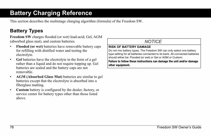
76 Freedom SW Owner’s Guide
Battery Charging ReferenceThis section describes the multistage charging algorithm (formula) of the Freedom SW.
Battery TypesFreedom SW charges flooded (or wet) lead-acid, Gel, AGM (absorbed glass mat), and custom batteries.• Flooded (or wet) batteries have removable battery caps
for refilling with distilled water and testing the electrolyte.
• Gel batteries have the electrolyte in the form of a gel rather than a liquid and do not require topping up. Gel batteries are sealed and the battery caps are not removable.
• AGM (Absorbed Glass Mat) batteries are similar to gel batteries except that the electrolyte is absorbed into a fiberglass matting.
• Custom battery is configured by the dealer, factory, or service center for battery types other than those listed above.
RISK OF BATTERY DAMAGEDo not mix battery types. The Freedom SW can only select one batterytype setting for all batteries connected to its bank. All connected batteriesshould either be: Flooded (or wet) or Gel or AGM or Custom.
Failure to follow these instructions can damage the unit and/or damageother equipment.
FSW Owners Guide.book Page 76 Tuesday, August 7, 2018 9:03 AM

97-0019-01-01 77
Battery Charging Reference
Charge Algorithm Stages
Three-Stage chargingIf three-stage charging is enabled, the Freedom SW will charge batteries in a sequence known as three-stage charging. Whenever qualified AC power is present at the inverter’s input, it passes power through to the connected load and begins charging the batteries. The charging voltage delivered to the battery depends on the battery’s:• Type setting• Temperature (by switch setting or battery temperature
sensor)• State of chargeThe three automatic stages are:• Bulk• Absorption• FloatSee Figure 35 for a graph of the three-stage charging profile.There is a fourth stage, equalization, which is initialized manually as it is only performed occasionally and only on flooded (or wet) batteries.
The charging cycle is a multistage (three-stage) process. Whenever qualified AC power is present at the inverter’s input, it passes power through to the connected load and begins charging the batteries.
Figure 35 Three-Stage Battery Charging Cycle
FSW Owners Guide.book Page 77 Tuesday, August 7, 2018 9:03 AM

78 Freedom SW Owner’s Guide
Battery Charging Reference
Bulk StageBulk charge is the first stage in the charging process and provides the batteries with a controlled, constant current. Once the battery voltage rises to the absorption voltage threshold, the charger switches to the absorption stage.
NOTE: When the charge cycle is interrupted, the charger will restart charging atthe beginning of the multistage algorithm.Exit Current Threshold can be effectively disabled by programming theamp-hour capacity to the minimum. In this case, absorption will only exitonce the Max Absorption timer expires.Charge current during equalize state (optional state not shown here) isnormally limited to 10% of the programmed amp-hour capacity setting. Ifthis setting is programmed to the maximum, the charge current duringequalize is instead limited to whatever is programmed for the maximumcurrent limit of the unit.Synchronized charge states are active when more than one chargingdevice is connected in the system via the Xanbus network.
• The first unit (Freedom SW) to enter bulk, causes all other chargers toenter bulk.
• The first Freedom SW to enter absorption causes all other FreedomSWs to enter absorption.
• The last Freedom SW ready to exit absorption triggers all FreedomSWs to exit absorption and exit charge.
Table 19 Preset Bulk Voltage Settings
Battery Type
Termination Voltage Preset Bulk Voltage12V models
24V models
12V models
24V models
Flooded 14.2 28.4 14.4 28.8Gel 14.0 28.0 14.2 28.4AGM 14.1 28.2 14.3 28.6Custom 14.4
(changeable)28.8 (changeable)
14.4 (changeable)
28.8 (changeable)
FSW Owners Guide.book Page 78 Tuesday, August 7, 2018 9:03 AM

97-0019-01-01 79
Battery Charging ReferenceAbsorption StageAbsorption charge is the second stage of battery charging and provides the batteries with a controlled, constant voltage. During this stage, the current drawn by the batteries slowly decreases. When this current falls below 2% of the battery capacity, or when the configurable Absorb Time expires, the charger switches to the Float or NoFloat stage, depending on the selected charge cycle. The timer begins when the battery voltage is above the bulk termination voltage for three minutes.
The Freedom SW transitions to the float stage if either one of the following two conditions are met:1. The charge current allowed by the batteries falls below
the exit current threshold, which is equal to 2% of the programmed battery capacity (for a 500 amp-hour battery bank, this would be 10 amps), for three minutes.
2. The Freedom SW has been in absorption for the programmed maximum absorption time limit. The default is 3 hours, but the time limit is programmable from 1 minute to 8 hours.
Table 20 Preset Absorption Voltage Settings
Battery TypePreset Absorption Voltage
12V models 24V modelsFlooded 14.4 28.8Gel 14.2 28.4AGM 14.3 28.6Custom 14.4
(changeable)28.8 (changeable)
NOTE: If there are DC loads on the batteries, the charger’s current maynever decrease to a level to initiate the next stage of charging. In this case,the charger would stay in absorption until the Absorb Time setting isreached.
NOTE: To make sure the charger does not remain in absorption for toolong, adjust Absorb Time on the Charger Settings menu. The timerbegins at the start of the absorption stage and terminates absorptioncharging if the charge current does not decrease to below 2 per cent ofthe battery capacity before the Absorb Time setting expires. The Absorb Time setting may be increased if the charge cycle continually runs the fullAbsorb Time in the absence of DC loads. This is an indication of too largea battery bank for the selected Absorb Time setting.
FSW Owners Guide.book Page 79 Tuesday, August 7, 2018 9:03 AM

80 Freedom SW Owner’s Guide
Battery Charging Reference
Float StageFloat charge maintains the batteries slightly above the self discharge voltage of the batteries. The charge current in float is the current necessary to maintain the batteries at the Float Voltage setting, limited only by the inverter's capability or other settings that limit the inverter's maximum charge rate. Float charging reduces battery gassing, minimizes watering requirements (for flooded batteries), and makes sure the batteries are in a constant state of readiness. When three-stage charging is selected, the charger automatically switches to the float stage after the batteries have received a bulk and absorption charge (see Figure 35). The batteries are maintained at the default float voltage level for the selected battery type or the voltage selected under Float Voltage on the Custom Battery Settings menu.
Table 21 Preset Float Voltage Settings
Battery TypePreset Float Voltage
12V models 24V modelsFlooded 13.5 27.0Gel 13.8 27.6AGM 13.4 26.8Custom 13.5
(changeable)27.0 (changeable)
NOTE: The battery voltage can increase above the float voltage whenusing an external charging device such as PV arrays, wind turbines, andmicro-hydro generators. Be sure to include appropriate chargemanagement equipment with all external DC sources.
FSW Owners Guide.book Page 80 Tuesday, August 7, 2018 9:03 AM

97-0019-01-01 81
Battery Charging ReferenceTwo-Stage Charging ProcessTwo-stage (or no float) mode differs from an ordinary three-stage charge mode in that it does not continuously maintain the battery at float voltage. Instead, the Freedom SW begins charging the battery in bulk mode whenever the battery voltage drops below the recharge level. While the battery voltage is above the recharge level the inverter’s AC transfer switch continues to pass power through from the utility grid to the loads, but does not actively charge the batteries. Two-stage mode increases efficiency of utility connected systems by reducing the amount of power consumed by the inverter and batteries compared to when the battery is continuously maintained at Float Voltage. This feature can extend the life of most batteries.
NOTE: If the AC input fails or drops below the lower VAC limit (as set inAC Settings), the complete multistage charge cycle (bulk, absorption,float/no float) restarts once the source AC recovers to within theacceptable range. If the batteries are already nearly full, the charge cyclewill take little time to complete.
Figure 36 Two-Stage Charging Cycle
FSW Owners Guide.book Page 81 Tuesday, August 7, 2018 9:03 AM

82 Freedom SW Owner’s Guide
Battery Charging Reference
NOTE: When the charge cycle is interrupted, the charger will restart charging atthe beginning of the multistage algorithm.Exit Current Threshold can be effectively disabled by programming theamp-hour capacity to the minimum. In this case, absorption will only exitonce the Max Absorption timer expires.Charge current during equalize state (optional state not shown here) isnormally limited to 10% of the programmed amp-hour capacity setting. Ifthis setting is programmed to the maximum, the charge current duringequalize is instead limited to whatever is programmed for the max currentlimit of the unit.Synchronized charge states are active when more than one chargingdevice is connected in the system via the Xanbus network.
• The first unit to enter bulk, causes all other chargers to enter bulk.• The first Freedom SW to enter absorption causes all other Freedom
SWs to enter absorption.• The last Freedom SW ready to exit absorption triggers all Freedom
SWs to exit absorption and exit charge.
FSW Owners Guide.book Page 82 Tuesday, August 7, 2018 9:03 AM

97-0019-01-01 83
Battery Charging Reference
Equalize ChargingMany battery manufacturers recommend periodic equalize charging to counter cell charge imbalance and capacity-robbing electrolyte stratification. Equalizing helps to improve battery performance and lifespan by encouraging more of the battery material to become active. Battery equalization is a controlled overcharging method that mixes up stratified electrolyte and reactivates unused areas of the plate material. Periodic equalizing can help to regularly restore batteries to a full and healthy state of charge.Consult the battery manufacturer's recommendation for equalize charging settings. Sealed batteries should never be equalized. Consult the battery manufacturer for optimal charging procedures when using sealed batteries. When Equalize mode is enabled, the battery is charged from bulk to absorption, and then to the equalize phase. The Freedom SW will transition from the absorption phase to equalize if:• the DC charge current is below 2% of the configured
battery capacity (for example, 8.8A for 440Ah)• the absorption time is exceeded (for example, 180 min)
After absorption, the maximum charge DC current is set to 10% of battery capacity (for example, 44A for 440Ah). See Figure 37. This constant current charge will continue until the voltage has increased to the equalize voltage at which point the battery will be regulated at the temperature-compensated equalize voltage. If the battery capacity is set to zero (Ah=0 effectively disables the exit current criteria for the absorption charge stage making the absorption stage defined by time only), the equalize charge current is fixed at maximum 100% of the charge rate.Equalization duration is fixed at one hour.
Table 22 Preset Equalization Voltage Settings
Battery TypePreset Equalization Voltage
12V models 24V modelsFlooded 16.0 32.0Gel n/a n/aAGM n/a n/aCustom 16.0
(changeable)32.0 (changeable)
FSW Owners Guide.book Page 83 Tuesday, August 7, 2018 9:03 AM

84 Freedom SW Owner’s Guide
Battery Charging Reference
Figure 37 Equalize Charging
FSW Owners Guide.book Page 84 Tuesday, August 7, 2018 9:03 AM

97-0019-01-01 85
TroubleshootingGeneral Troubleshooting GuidelinesThis section will help you narrow down the source of any problem you may encounter. Please read the following troubleshooting steps:1. Check for a warning or fault message on the Xanbus SCP
or a fault code on the inverter information panel. If a message is displayed, record it immediately.
2. As soon as possible, record the conditions at the time the problem occurred. These details should include the following information:• Loads the Freedom SW was running or attempting to
run• Battery condition at the time of failure (battery
voltage or temperature, for example), if known• Recent sequence of events (for example, charging
had just finished, utility grid had failed but the inverter did not come on)
• Any known unusual AC input factors such as low voltage or unstable generator output
• Extreme conditions which may have existed at the time (temperature or moisture, for example).
3. Attempt the solution indicated in these guidelines.4. If your inverter information panel or Xanbus SCP is not
displaying a Fault LED, check the following list to make sure that the present state of the installation allows proper operation of the unit. Read these guidelines carefully.
❐ Is the Freedom SW located in a clean, dry, adequately ventilated area?
❐ Have the AC input breakers opened? If so, your pass-through load may have exceeded the rating of one or more of the input breakers.
❐ Are the battery cables adequately sized and short enough? See the Installation Guide for more information.
❐ Is the battery in good condition and are all DC connections tight?
❐ Are the AC input and output connections and wiring in good condition?
❐ Are the configuration settings correct for your particular installation?
❐ Are the display panel and the communications cable properly connected and undamaged?
❐ Is the battery temperature sensor and its cable properly connected and undamaged?
FSW Owners Guide.book Page 85 Tuesday, August 7, 2018 9:03 AM

86 Freedom SW Owner’s Guide
Troubleshooting
5. Contact Customer Service for further assistance. Please be prepared to describe details of your system installation and provide the model and serial number of the unit. See the front and/or back of the manual for contact information.
Inverter ApplicationsThe Freedom SW performs differently depending on the AC loads connected to it. If you are having problems with any of your loads, read this section.
Resistive LoadsResistive loads are the easiest and most efficient to drive. Voltage and current are in phase, which means they are in step with one another. Resistive loads generate heat in order to accomplish their tasks. Toasters, coffee pots, and incandescent lights are typical resistive loads. It is usually impractical to run larger resistive loads—such as electric stoves and water heaters—from an inverter due to their high current requirements. Even though the inverter may be able to accommodate the load, the size of battery bank will limit inverter run time.
Motor LoadsInduction motors (AC motors without brushes) require up to six times their running current on startup. The most demanding are those that start under load (for example, compressors and pumps). Of the capacitor start motors (typical in drill presses and band saws, for example), the largest you can expect to run is one horsepower. Universal motors are generally easier to start. Check that the Locked Rotor Amps (LRA) rating of the motor load does not exceed the maximum surge current rating of the inverter. Since motor characteristics vary, only testing will determine whether a specific load can be started and how long it can be run.If a motor fails to start within a few seconds or loses power after running for a time, it should be turned off. When the inverter attempts to start a load that is greater than it can handle, the inverter may shut down from an AC overload fault.
Problem LoadsVery Small Loads If the power consumed by a device is less than the threshold of the search mode circuitry, and search mode is enabled, the inverter will not run. Most likely the solution will be to disable Search mode or lower the sense threshold.
FSW Owners Guide.book Page 86 Tuesday, August 7, 2018 9:03 AM

97-0019-01-01 87
TroubleshootingFluorescent Lights and Power Supplies Some devices cannot be detected when scanned by search mode circuitry. Small fluorescent lights are the most common example. Some computers and sophisticated electronics have power supplies that do not present a load until line voltage is available. When this occurs, each unit waits for the other to begin. To drive these loads, either a small companion load like a light bulb rated for more than the Search Watts setting must be used to bring the inverter out of search mode, or the inverter may be programmed to remain on by disabling Search mode. (See “Using Search Mode” on page 45.)Clocks You may notice that your clocks are not accurate. Some of the clocks on your appliances may reset when the Freedom SW is in search mode.Searching When the inverter is in search mode, it may fail to start some loads even though the rated wattage on the load is more than the Search Watts setting. Disable Search or apply an additional load (companion load) to make the inverter exit search mode.
FSW Owners Guide.book Page 87 Tuesday, August 7, 2018 9:03 AM

88 Freedom SW Owner’s Guide
Troubleshooting
Troubleshooting the Freedom SW via the SCPThe Freedom SW is designed with a number of protection features to provide efficient operation. If, however, you have any problems operating your inverter/charger read this troubleshooting chapter.If you cannot resolve the problem, record the information about your system. This information will help your dealer or customer service to assist you better when you contact them.
When a detected fault or warning message appears, you can acknowledge the message to clear the screen. To acknowledge a fault or warning message, press the Enter button on the SCP. This action does not clear the fault or warning condition, so you should consult “Detected Fault Messages” on page 91 and “Detected Warning Messages” on page 100 for suggested actions after you have acknowledged
the message. Refer to the Xanbus System Control Panel Owner’s Guide for more information on detected faults and warnings.
Detected Fault TypesThere are three types of detected fault messages: automatic faults, manual faults, and escalating automatic faults. Table 1 describes how they differ in their behavior and how you can respond to them when they appear on the SCP.
ELECTRICAL SHOCK HAZARDDo not disassemble the inverter/charger. The Freedom SW contains nouser-serviceable parts.Failure to follow these instructions will result in death or serious injury.
Table 1 Detected Fault Types and BehaviorsFault type BehaviorAutomatic fault
Clears automatically if the detected condition that generated the message goes away. You can also acknowledge automatic faults without waiting for them to clear automatically.
FSW Owners Guide.book Page 88 Tuesday, August 7, 2018 9:03 AM

97-0019-01-01 89
TroubleshootingTo view a fault list:1. On the Select Device menu, highlight System and press
Enter.2. On the System Settings menu, highlight View Fault List.3. Press Enter.
Manual fault Requires you to clear it by:• Selecting Clear Faults on the Freedom
SW or on the device that generated the detected fault (if the condition still exists, the fault message reappears).
• Correcting the condition that detected the fault.
Escalating automatic faults
Clears automatically if the detected fault condition goes away, just like an automatic fault. However, if an escalating automatic fault occurs several times within a defined time period, the escalating automatic fault becomes a manual fault, requiring user intervention. For example, if three detected faults occur in one minute, it will no longer clear itself but becomes a manual fault. Then, you must identify the problem, correct the condition that detected the fault, and clear the fault or reset the device.
Table 1 Detected Fault Types and BehaviorsFault type Behavior
FSW Owners Guide.book Page 89 Tuesday, August 7, 2018 9:03 AM

90 Freedom SW Owner’s Guide
Troubleshooting
Detected Warning TypesThere are two types of detected warnings: automatic and manual. When the Freedom SW detects a warning condition, it displays a warning message on the SCP.Table 2 describes how they differ in their behavior and in how you can respond to them when they appear on the SCP.To view a warning list:1. On the Select Device menu, highlight System and press
Enter.2. On the System Settings menu, highlight View Warning
List.3. Press Enter.
Table 2 Detected Warning Types and BehaviorWarning type BehaviorAutomatic warning
Clears automatically if the detected condition that generated the message goes away. You can also acknowledge automatic warnings without waiting for them to clear automatically.
Manual warning
Requires you to acknowledge it before you can proceed with configuring or operating the Freedom SW. Manual warnings are usually in the form of a Yes/No question that you may acknowledge by pressing the Enter button on the SCP for Yes and the Func button for No.Refer to the Xanbus System Control Panel Owner’s Guide for more information.
FSW Owners Guide.book Page 90 Tuesday, August 7, 2018 9:03 AM

97-0019-01-01 91
Troubleshooting
Table 3 provides a detailed description of the detected fault messages and solutions. If you are unable to resolve the problem after referring to this table, contact your dealer or Customer Service.
Table 3 Detected Fault Messages
Fault Number Message Fault Type Cause Solution
F1 AC Output under voltage
Escalating Auto Fault. Must occur 3 times in 30 seconds before becoming a manual fault.
Inverter voltage is under 100 volts.
Remove excessive load.
F2 AC Output over voltage
Escalating Auto Fault. Must occur 3 times in 30 seconds before becoming a manual fault.
Inverter voltage is over 135 volts.
Check if there is an external power source that is running parallel to the inverter’s output.
F17 Relays Welded Manual AC backfeed from welded relay.
Service required.
F18
FSW Owners Guide.book Page 91 Tuesday, August 7, 2018 9:03 AM

92 Freedom SW Owner’s Guide
Troubleshooting
F44 Battery Over Temperature
Automatic Battery temperature is over 140 °F (60 °C).Poor battery compartment ventilation.
Stop charging if necessary.Check cable connections.Check battery voltage/current and temperature. If battery is not accepting charge, it may need to be replaced.Check for excessive ambient temperature and adequate ventilation in the battery compartment.
Automatic BTS may be damaged. If the unit displays a temperature of over 212 °F (100 °C), the BTS will need to be replaced.
F46 Controller Error
Manual Unit’s control board may be damaged.
Service is required.
Table 3 Detected Fault Messages
Fault Number Message Fault Type Cause Solution
FSW Owners Guide.book Page 92 Tuesday, August 7, 2018 9:03 AM

97-0019-01-01 93
Troubleshooting
F47 DC Under Voltage (Immediate)
Automatic Immediate battery under voltage fault.
Check battery condition (short or open cells) and ensure correct voltage.Battery state charge or capacity is so low that the DC voltage collapses when inverter load is applied.Inverter load is so large that the DC voltage collapses when inverter load is applied.
F48 DC Under Voltage (Fault)
Automatic Voltage at the DC input terminals is below the Low Battery Cut Out (LBCO) setting for 10 seconds.
Check for the correct battery voltage at the inverter's DC input terminals.Check for external DC loads on the batteries.Check condition of batteries and recharge if necessary.Reduce the Low Battery Cut Out (LBCO) setting.Battery bank capacity may be inadequate for the loads in the system.
Table 3 Detected Fault Messages
Fault Number Message Fault Type Cause Solution
FSW Owners Guide.book Page 93 Tuesday, August 7, 2018 9:03 AM

94 Freedom SW Owner’s Guide
Troubleshooting
F49 DC Over Voltage
Automatic Voltage at the DC input terminals is above the High Battery Cut Out Setting
Clear the fault and attempt restart. Ensure battery voltage is 10–16 VDC at Freedom SW terminals. Check all other charging source outputs, battery cables.
F52-F56 EEPROM ERROR Manual A problem has been detected with the internal memory.
Clear the fault and check the latest configuration made or any recent configurations. If fault detection reoccurs or occurs frequently, service is required.
Table 3 Detected Fault Messages
Fault Number Message Fault Type Cause Solution
FSW Owners Guide.book Page 94 Tuesday, August 7, 2018 9:03 AM

97-0019-01-01 95
Troubleshooting
F57 FET1 Over Temperature
Automatic Ambient temperature may be too high.
Ensure adequate ventilation around the Freedom SW.Allow inverter to cool down and try restarting.
Operating too large of a load for too long while inverting.
Remove excessive inverter loads.
Inverter cooling fan may have failed.
If the temperature is above 104 °F (40 °C), the fan should be on. Hold your hand or a piece of paper to the inverter vent to check if the fan is working.Both fans should be active at the same time.
Inverter airflow intake may be blocked.
Increase the clearance around the inverter and/or unclog the airflow intake vents.
F58 FET2 Over Temperature
Automatic Same as F57. Same as F57.
Table 3 Detected Fault Messages
Fault Number Message Fault Type Cause Solution
FSW Owners Guide.book Page 95 Tuesday, August 7, 2018 9:03 AM

96 Freedom SW Owner’s Guide
Troubleshooting
F59 GOCFG process failed
Manual The unit may be running outdated firmware.
Clear the fault and check if the latest firmware is installed. If not, download and install the latest firmware from the website.
F62 Invalid Interrupt
Manual Unit’s control board may be damaged.
Service is required.
F63 Power Board Temp unreadable
Automatic Temperature sensor is damaged.
Service required.
F64 AC overload Escalating Auto Fault. Must occur 3 times in 60 seconds before becoming a manual fault.
Persistent excessive inverter current above rated current.
Avoid loads with long surge current.
F67 Watchdog Error Manual Unit’s control board may be damaged.
Service is required.
F68 Transformer Over Temperature
Automatic Same as F57. Same as F57.
Table 3 Detected Fault Messages
Fault Number Message Fault Type Cause Solution
FSW Owners Guide.book Page 96 Tuesday, August 7, 2018 9:03 AM

97-0019-01-01 97
Troubleshooting
F69 External Sync Failed
Automatic When Series stacking— the Stacking cable is not installed.
Install the Stacking cable to connect the two inverter/chargers.
F70 Unique Dev# Needed
Automatic When stacking (Series or Parallel)—if two units have the same Device Number.
Change the Device Number of one unit. See “Setting the Device Number” on page 71.
F71 Too Many Masters
Automatic When stacking (Series or Parallel)—if two units are configured as Master units.
Change one unit to a Slave unit. See Stack Mode under “Stacking Configuration Menu” on page 68 in Table 17.
F73 Transformer Temp unreadable
Automatic Temperature sensor is damaged.
Service required.
Table 3 Detected Fault Messages
Fault Number Message Fault Type Cause Solution
FSW Owners Guide.book Page 97 Tuesday, August 7, 2018 9:03 AM

98 Freedom SW Owner’s Guide
Troubleshooting
F74 Other Unit Invert Fault
Automatic When stacking (Series or Parallel)—if one of the units encounters a fault that needs to be resolved.
Clear the primary fault on the unit that caused this fault.
F75 Master Inverter Lost
Automatic When Parallel stacking—if the Slave unit cannot detect the Master unit in the Xanbus network.
Make sure that the two units are connected in the same Xanbus network. Check cable connections and ensure that the plugs are neatly inserted in the ports. Check if the Xanbus network is properly installed with network terminators.
F76 No Masters Automatic When stacking (Series or Parallel)—if all units are configured as Slave.
Assign the other unit as Master.
F77
F79 Battery Sensor Short
Automatic The BTS has been damaged.
Replace the BTS.
Table 3 Detected Fault Messages
Fault Number Message Fault Type Cause Solution
FSW Owners Guide.book Page 98 Tuesday, August 7, 2018 9:03 AM
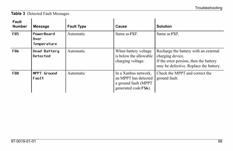
97-0019-01-01 99
Troubleshooting
F85 PowerBoard Over Temperature
Automatic Same as F57. Same as F57.
F86 Dead Battery Detected
Automatic When battery voltage is below the allowable charging voltage.
Recharge the battery with an external charging device.If the error persists, then the battery may be defective. Replace the battery.
F88 MPPT Ground Fault
Automatic In a Xanbus network, an MPPT has detected a ground fault (MPPT generated code F56).
Check the MPPT and correct the ground fault.
Table 3 Detected Fault Messages
Fault Number Message Fault Type Cause Solution
FSW Owners Guide.book Page 99 Tuesday, August 7, 2018 9:03 AM

100 Freedom SW Owner’s Guide
Troubleshooting
Table 4 provides a detailed description of the detected warning messages and solutions. If you are unable to resolve the problem after referring to this table, contact your dealer or Customer Service.
Table 4 Detected Warning Messages
Fault Number Message Cause Solution
W48 DC under voltage (Warning)
Voltage at the DC input terminals is below the Low Battery Cut Out (LBCO) setting.
Check for the correct battery voltage at the inverter's DC input terminals.Check for external DC loads on the batteries.Check condition of batteries and recharge if necessary.Reduce the Low Battery Cut Out (LBCO) setting.Battery bank capacity may be inadequate for the loads in the system.
W72 AC Out Assoc Mismatched
In a stacking configuration—the AC In settings are not the same for both units.
Change the AC In setting of both units in the stacking configuration to be the same. See “Stacking Configuration Menu” on page 68.
W87 Inconsistent Frequencies
In a stacking configuration—the AC input low and high frequency settings are not the same for both units.
Change the AC input low and hi frequency settings of both units in the stacking configuration to be the same. See “ACIn Settings” on page 64.
FSW Owners Guide.book Page 100 Tuesday, August 7, 2018 9:03 AM

97-0019-01-01 101
Troubleshooting
W92 Input Connected to 3-Phase AC
Table 4 Detected Warning Messages
Fault Number Message Cause Solution
FSW Owners Guide.book Page 101 Tuesday, August 7, 2018 9:03 AM

FSW Owners Guide.book Page 102 Tuesday, August 7, 2018 9:03 AM
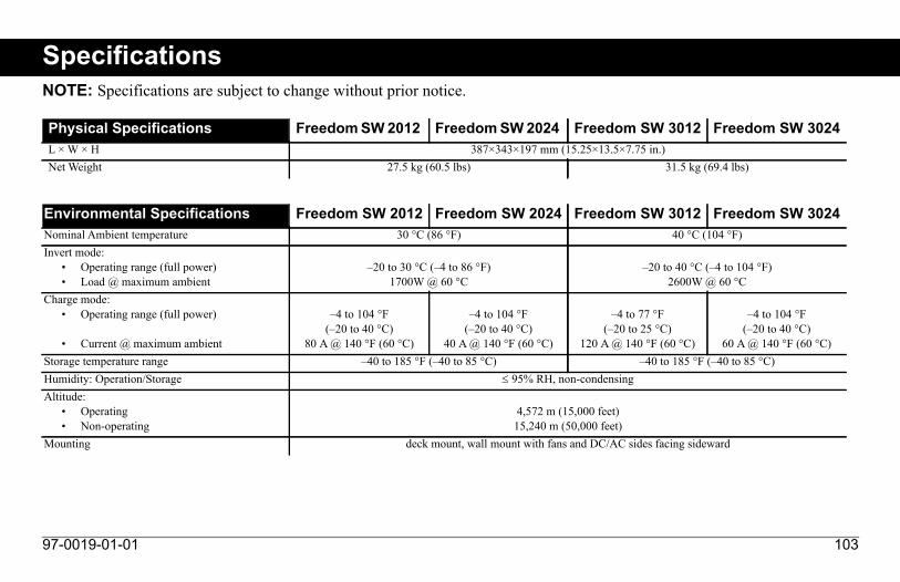
97-0019-01-01 103
SpecificationsNOTE: Specifications are subject to change without prior notice.
Physical Specifications Freedom SW 2012 Freedom SW 2024 Freedom SW 3012 Freedom SW 3024L × W × H 387×343×197 mm (15.25×13.5×7.75 in.)Net Weight 27.5 kg (60.5 lbs) 31.5 kg (69.4 lbs)
Environmental Specifications Freedom SW 2012 Freedom SW 2024 Freedom SW 3012 Freedom SW 3024Nominal Ambient temperature 30 °C (86 °F) 40 °C (104 °F)Invert mode:
• Operating range (full power)• Load @ maximum ambient
–20 to 30 °C (–4 to 86 °F)1700W @ 60 °C
–20 to 40 °C (–4 to 104 °F)2600W @ 60 °C
Charge mode: • Operating range (full power)
• Current @ maximum ambient
–4 to 104 °F(–20 to 40 °C)
80 A @ 140 °F (60 °C)
–4 to 104 °F(–20 to 40 °C)
40 A @ 140 °F (60 °C)
–4 to 77 °F(–20 to 25 °C)
120 A @ 140 °F (60 °C)
–4 to 104 °F(–20 to 40 °C)
60 A @ 140 °F (60 °C)Storage temperature range –40 to 185 °F (–40 to 85 °C) –40 to 185 °F (–40 to 85 °C)Humidity: Operation/Storage 95% RH, non-condensingAltitude:
• Operating• Non-operating
4,572 m (15,000 feet)15,240 m (50,000 feet)
Mounting deck mount, wall mount with fans and DC/AC sides facing sideward
FSW Owners Guide.book Page 103 Tuesday, August 7, 2018 9:03 AM

104 Freedom SW Owner’s Guide
Specifications
NOTE: All inverter specifications are at nominal conditions: 12 (or 24) volts DC inverting 120 volts AC, unless otherwise specified.
Inverter Specifications Freedom SW 2012 Freedom SW 2024 Freedom SW 3012 Freedom SW 3024Output wave form pure sine wave (true sine wave)Output power (continuous) 2000 W (up to 30 °C) 3000 W (up to 40 °C)Output power (5 seconds) 4000 W 6000 WOutput current 17 A 24 APeak output current 55 A 80 AOutput frequency 60 Hz ± 0.2 Hz 60 Hz ± 0.2 HzOutput voltage 120 VAC 120 VACAC output connection/s Single Split phase in/dual out,
Dual in/dual outPeak efficiency 90% 94% 90% 94%No-load current draw (Inverter On) <3 ADC <1.5 ADC <3 ADC <1.5 ADCStandby current draw (Inverter Off) <0.25 ADC <0.15 ADC <0.25 ADC <0.15 ADCInput DC voltage range 10–16 VDC 20–32 VDC 10–16 VDC 20–32 VDCLow battery voltage shutdown cut-off 10.5 V (selectable) 21.0 V (selectable) 10.5 V (selectable) 21.0 V (selectable)High battery voltage shutdown cut-off 16.5 V (selectable) 33.0 V (selectable) 16.5 V (selectable) 33.0 V (selectable)
FSW Owners Guide.book Page 104 Tuesday, August 7, 2018 9:03 AM

97-0019-01-01 105
Specifications
NOTE: All charging specifications are at nominal conditions: ambient temperature of 77 °F (25 °C), 120 VAC, 60 Hz input, unless otherwise specified.
Charger Specifications Freedom SW 2012 Freedom SW 2024 Freedom SW 3012 Freedom SW 3024Charging method Three-stage charge (Bulk, Absorption, Float)
Two-stage charge (Bulk, Absorption)The default charging method is three-stage.
Without a battery temperature sensor Three settings with the following temperature values:Cool 50 °F (10 °C)Warm 77 °F (25 °C)Hot 104 °F (40 °C)
The default setting is Warm and it can only be changed by the factory, a dealer, or a service centre.With a battery temperature sensor (included) The temperature compensation coefficients on a
12-volt battery are as follows:Flooded: 27 mV × (25 °C – BTS °C)
Gel: 27 mV × (25 °C – BTS °C)AGM: 21 mV × (25 °C – BTS °C)
The temperature compensation coefficients on a24-volt battery are as follows:
Flooded: 54 mV × (25 °C – BTS °C)Gel: 54 mV × (25 °C – BTS °C)
AGM: 42 mV × (25 °C – BTS °C)Output current (maximum) 100 ADC 50 ADC 150 ADC 75 ADCOutput voltage 12 VDC 24 VDC 12 VDC 24 VDCOutput voltage range 5–16 VDC 12–32 VDC 5–16 VDC 12–32 VDCEqualization cycle Automatic, Manual by Xanbus SCP Automatic, Manual by Xanbus SCPOptimal charging efficiency > 85% > 85%AC input power factor (at full charge rate) > 0.98 > 0.95AC input current 24A max. (including pass-thru) 24A max. (including pass-thru)AC input voltage 120 VAC 120 VACAC input voltage range 85–140 VAC 85–140 VACDead battery charge voltage > 5 VDC > 12 VDC > 5 VDC > 12 VDC
FSW Owners Guide.book Page 105 Tuesday, August 7, 2018 9:03 AM

106 Freedom SW Owner’s Guide
Specifications
NOTE: All transfer specifications are at nominal conditions: ambient temperature of 77 °F (25 °C), 120 VAC, 60 Hz input, unless otherwise specified.
Supported AC input types Single input (up to 30 amps) Split phase (up to 30 amps per line)Dual input (up to 30 amps per line)
Transfer and General Specifications All ModelsTransfer time—utility to invert < 20 msMinimum AC input voltage for transfer 85 VACMaximum AC input voltage for transfer 135 VACMinimum AC input frequency for transfer 45 HzMaximum AC input frequency for transfer 70 HzCooling Fan-cooled, temperature controlled.
Regulatory Approvals All ModelsSafety CSA 107.1,
UL 458 5th Ed. with marine supplement,ABYC E11 - Alternating Current and Direct Current Electrical Systems on Boats, and
ABYC A31 - Battery Chargers and Inverters.EMC FCC Part 15, Class B
Industry Canada ICES-003, Class B
FSW Owners Guide.book Page 106 Tuesday, August 7, 2018 9:03 AM

FSW Owners Guide.book Page i Tuesday, August 7, 2018 9:03 AM

Schneider Electric Solar Inverters USA Inc.+1 800 670 0707 +1 408 987 6030 www.xantrex.com
97-0019-01-01 Rev G Printed in China
FSW Owners Guide.book Page ii Tuesday, August 7, 2018 9:03 AM