80k - federal signal corporation
TRANSCRIPT

MAN-80KREV. 14 FEB 03
80K AMPLIFIER Sirens Sirens with P.A.
Sirens with P.A. and Switching INSTALLATION & OPERATION
FS UNITROL * 1108 RAYMOND WAY * ANAHEIM, CA 92801 * (714)871-3336 * Fax (714)871-3418WWW.UNITROL.COM

Table of Contents Check Model Number of Unit to be Installed See Pages Listed Below that Apply
Model 80K AmplifierBlowout Proof Transistors - Section I - pg. 1Intrusion Alarm - Section VIII - pg. 9Specifications - Section XI - pg. 12Two-Tone Sounds - Section IX & X - pgs.10-11
Model 80KM Kawasaki Motorcycle SirenOperation & Installation - Section II - pg. 2P.A. Kit Installation - Section IV - pg. 4
Model 180K Basic SirenOperation & Installation - Section III - pg. 3Intrusion Alarm Connections - Section VIII - pg. 9P.A. Kit Installation - Section IV - pg. 4
Model 183KStandard & Optional Features - Section IV - pg. 5Siren & Warning Light Control - Section IV - pg. 5Rear Connections - Section IV - pg. 5Horn Ring Connections- Section IV - pg. 5
Series 280 & 480 Siren/P.A. SystemOperation - Section V - pg. 6Installation - Section VI & VII - pgs. 7 & 8Intrusion Alarm Connections - Section VIII - pg. 9Two-Tone Siren Sounds - Section X - pg. 11Warning Light Connections - Section VII - pg. 8
MiscellaneousIndicator Light Replacement - Section XI - pg. 12Power Jack Plug Wiring - Section XI - pg. 12Tape Jack Plug Wiring - Section XI - pg. 12Trouble Shooting - pgs. 1 & 12Warranty and Where to Call- Section XII - pg. 13
i

SECTION I - BASIC SYSTEMModel 80K
USED WITH ALL MODELSContaining electronic components for generatingsounds, the Model 80K amplifier is the basic partof the siren and common to all models described inthis Manual. It will be found in the same cabinetwith it’s controls or in a separate cabinet remotefrom it’s controls.External Components Include:
a) Park Kill Wire- deactivates siren whengrounded.b) Power Transistors (Rear) - Electrically“hot” during Siren/P.A. operation. Contactwith metal objects will destroy them.c) Fuse (Rear) - In unlikely event of failure,do not overfuse.
PRECAUTIONS1. Although the 80K has an extremely wide operatingtemperature range (-40F to + 185F), underhoodinstallation where temperatures exceed 230F is notadvised.2. Cabinet is not waterproof.
BLOW-OUT PROOF TRANSISTOR PROTECTION1. Output transistors, blown out in normal sirens byfailures of the siren speaker or its wiring are protectedin the Unitrol 80K by automatic circuitry.
a) Short-circuited speaker or wiring stopssiren sounds. A soft “popping” noise fromthe speaker or amplifier will occur 60 timesper minute.b) Blown-out speaker (open coil) ordisconnected speaker wire causes amplifierto emit siren sounds from amplifier but notfrom speaker.c) Primary input voltage above 16Vdc willcause shutdown of tone generating stages. Nosounds will be emitted by the amplifier or sirenspeaker.
2. In all instances, amplifier operation will automaticallyresume when the external defect is repaired.
ASSEMBLY METHODS1. Amplifier can be used with control units asfollows:
a) Remote - Amplifier is installedremotely from control unit andconnected by a 4 foot or 15 footcable.b) Single-Unit - Amplifier / controlunit are plugged together andhoused in one cabinet.
Page 1

SECTION II - KAWASAKI SIREN Model 80KM
STANDARD & OPTIONAL FEATURES1. Model U80KM consists of a UMCO83 cableand Model 80K Amplifier. The cable interfacesthe amplifier with Kawasaki handlebar switchesthat control WAIL and YELP.2. Optional connections or equipment can include:
a) Air Hornb) Microphone & Cable (PA Kit)UPA1 - UMNCT-SB & UCARK
INSTALLATION1. Set slide switch on bottom of amplifier to matchpower rating of siren speaker.2. Install amplifier in left saddlebag with transistorsdown, connector up. U-brackets may be used formounting, but amplifier life will be prolonged by“floating” amplifier in 1-1/2” - 2” medium-density foam.
CONNECTIONS1. Locate Kawasaki wiring harness for siren. Removalof gas tank and / or inspection plate at left side may benecessary. Wires have insulated bullet connectors.2. Connect siren speaker to BROWN wires from 12-pinamplifier connector.3. Make balance of connections by matching Kawasakiwire colors with amplifier harness wires.
AIR HORN1. +12V applied to the amplifier’s “AIR HORN” wire(3-pin power connector) operates the air horn, +12Vcan be supplied by a separate switch or the regular hornbutton.2.Separate Switch - Install a light duty (1 to 3 ampere)Single-Pole, Single-Throw (SPST), normally open pushbutton switch.
a)Using 18 ga. (minimum ), wire connect one switchterminal (either one) to source of +12V.b) Connect other terminal to “AIR HORN” wire.
3. Horn Button - The Kawasaki horn circuit is grounded (-)which must be inverted to +12V by a relay. Using 18ga. wirefor new connections, proceed as follows:
a) Disconnect horn button wire from regular horns.b) Install a light duty (1A) Single-Pole, Single-Throw(SPST) relay (customer supplied).c) Of the relay’s two coil connections, connecteither one to battery (+). Connect other to horn wirebutton.d) Of the relay’s two contact point connections,connectone (either one) to battery (+). Connect other one to“AIR HORN” wire.
See diagram below for schematic details noting thatone coil terminal and one contact terminal both cango to the same battery (+) source.
Page 2
SECTION III - BASIC SIREN SYSTEM Model 180K
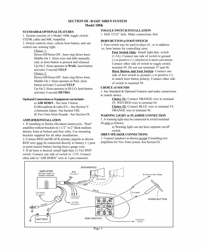
STANDARD & OPTIONAL FEATURES1. System consists of a Model 180K toggle switch,CO29K cable and 80K Amplifier.2. Switch controls siren, vehicle horn button, and cancontrol one warning light:
Choice 1:Down-Off/Siren-Off : horn ring blows horn.Middle-On 1: Siren rises and falls manuallyonly as horn button is pressed and released.Up-On 2: Siren operates in WAIL; horn buttonactivates 5-second YELP.Choice 2:Down-Off/Siren-Off : horn ring blows horn.Middle-On 1: Siren operates in Wail ; hornbutton activates 5-second YELP.Up-On 2: Siren operates in HI-LO; horn buttonactivates 5-second HETRO.
TOGGLE SWITCH INSTALLATION1. Drill 15/32” hole. Make connections first.
HORN BUTTON or FOOT SWITCH1. Foot switch may be used in place of , or in addition to, horn button for controlling siren.
Foot Switch Only- Install light-duty switch(1-3A). Connect one side of switch to ground(-) or positive (+) ,whichever is most convenient.Connect other side of switch to toggle switchterminal #9. Do not use terminals #7 and #8.Horn Button and Foot Switch- Connect oneside of foot switch to ground (-) or positive (+)to match horn button polarity. Connect other sideof switch to terminal #9.
Optional Connections or Equipment can include:a) AIR HORN - See item 3 below.b) Microphone & radio P.A. - See Section V.c) Intrusion Alarm - See Section VIII.d) Two-Tone Siren Sounds - See Section IX.
CHOICE of SOUNDS1. See Standard & Optional Features and make connectionsto match choice.
Choice #1: Connect ORANGE wire to terminal#3; WHT/RED wire to terminal #6.Choice #2: Connect BLUE wire to terminal #3;ORANGE wire to terminal #6.
AMPLIFIER INSTALLATION1. If installing in Harley-Davidson motorcycle, “float”amplifier without brackets in 1-1/2” to 2” thick mediumdensity foam at bottom and four sides. Use mountingbrackets supplied for all other installations.2. Connect RED and BLACK primary pigtails as shown.RED wire must be connected directly to battery (+) postor point nearest battery having heavy gauge wire.3. If air horn is desired, install light duty (1-3A) SPSTswitch. Connect one side of switch to +12V. Connectother side to “AIR HORN” wire in 3-pin connector.
WARNING LIGHT or FLASHER CONNECTION1. A warning light may be connected to switch terminal#6 only as follows:
a) Warning light can not have separate on/offswitch.
SIREN SPEAKER CONNECTIONS1. Connect speakers as shown except if installing twoamplifiers for Two-Tone system. See Section IX.
Page 3

Page 4
SECTION IV- PUBLIC ADDRESS KITS For Models 80KM & 180K
OPTIONAL PA KIT1. Models 80KM & 180K are shipped with cableassemblies having four wires (Yellow, Gray, Green& Purple) intended for connection of public addresskit.2. One PA kit is available (UPA1).
OPERATION1. “PA” kit requires no switching. PA announcements aremade by pressing the microphone button and talking. Sirensounds are stopped until mic button is released.
INSTALLATION1. Locate area for jack installation. Allow 1”diameter clearance space for back portion ofjack. Drill 3/8” diameter mounting hole.2. Un-plug Yellow and Gray wires in 12-pinconnector cable. Extend wires as needed andconnect with wires of same colors comingfrom jack.3. Connect Black ground wire from jack tovehicle chassis(-).4. Plug microphone into jack.5. Adjust gain potentiometer for desired output.

Page 5
Section IV Cont. MODEL 183K
STANDARD & OPTIONAL FEATURES
1. The system consists of a Model UM183K controller, a UM80K amplifier and a UCO30-4 cable, ( 4 foot version), or a UCO30-15, ( 15 foot version).
2. The UM183K controller can control the siren and warning lights.
3. A 60 amp progressive slide switch supplies 20 amps of power per switch position.
4. Horn Ring Transfera. Horn and Horn Ring connections on the rear of a unit MUST be made to permit operation of Manual siren and Yelp of Hetro Override.See siren & warning light control for correct hookup of the Horn Ring circuit.
5. Indicator lights to alert the user that there is an active circuit at a glance.
Optional Equipment can include:1. UPA2
a. UCAR-183K, P.A. cableb. UMNCT-SB, P.A. microphone
2. UDMK, Dual Mode
SIREN & WARNING LIGHT CONTROL
The progressive slide switch position 1, 2, & 3turn on warning lights. Position 3 turns on thesiren and horn ring controls.
The toggle switch controls the siren’s mode ofoperation during slide switch position 3.
OFF - No Siren.MAN - Allows the siren to operate in manual mode.AUTO - Siren & override functions automatically.
REAR CONNECTIONS
1. B1 terminals from left to right are:a. Grd - Battery Groundb. SPK - Siren Driver.c. SPK - Siren Driver.d. HORN - Spliced into the car horn circuit.e. Ring - Spliced into the car horn circuit.
2. B2 terminals from left to right are:a. +12V - Battery positive.b. 1-2-3 - Slide switch output during position 1, 2, & 3.c. 2-3 - Slide switch output only during switch positions 2 & 3.d. 3 - Slide switch output during position 3 only.e. 1- Slide switch output during position 1 only.
HORN RING CONNECTIONS
1. Cut wire apart between either the Horn Ring and the Horn Relay or between the Horn Relay and the vehicle Horn. Extend the wires to reach the rear of the control unit.
2. Connect the wires to the B1 terminals screws marked HORN and RING.
DO NOT REVERSE THE WIRES.
SECTION V - SIREN/PA SYSTEM Operating Models 280K & 480K
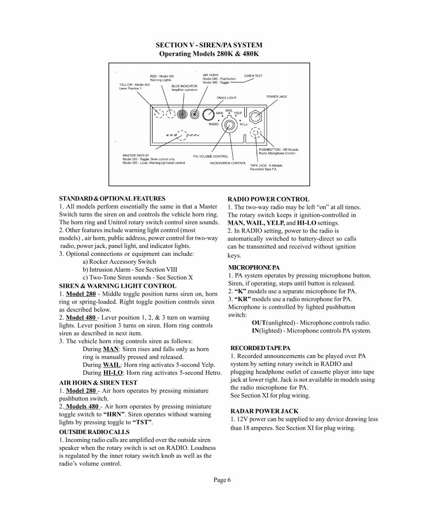
STANDARD & OPTIONAL FEATURES1. All models perform essentially the same in that a MasterSwitch turns the siren on and controls the vehicle horn ring.The horn ring and Unitrol rotary switch control siren sounds.2. Other features include warning light control (mostmodels) , air horn, public address, power control for two-way radio, power jack, panel light, and indicator lights.3. Optional connections or equipment can include:
a) Rocker Accessory Switchb) Intrusion Alarm - See Section VIIIc) Two-Tone Siren sounds - See Section X
RADIO POWER CONTROL1. The two-way radio may be left “on” at all times.The rotary switch keeps it ignition-controlled inMAN, WAIL, YELP, and HI-LO settings.2. In RADIO setting, power to the radio isautomatically switched to battery-direct so callscan be transmitted and received without ignitionkeys.
SIREN & WARNING LIGHT CONTROL1. Model 280 - Middle toggle position turns siren on, hornring or spring-loaded. Right toggle position controls sirenas described below.2. Model 480 - Lever position 1, 2, & 3 turn on warninglights. Lever position 3 turns on siren. Horn ring controlssiren as described in next item.3. The vehicle horn ring controls siren as follows:
During MAN: Siren rises and falls only as hornring is manually pressed and released.During WAIL: Horn ring activates 5-second Yelp.During HI-LO: Horn ring activates 5-second Hetro.
AIR HORN & SIREN TEST1. Model 280 - Air horn operates by pressing miniaturepushbutton switch.2. Models 480 - Air horn operates by pressing miniaturetoggle switch to “HRN”. Siren operates without warninglights by pressing toggle to “TST”.
Page 6
MICROPHONE PA1. PA system operates by pressing microphone button.Siren, if operating, stops until button is released.2. “K” models use a separate microphone for PA.3. “KR” models use a radio microphone for PA.Microphone is controlled by lighted pushbuttonswitch:
OUT(unlighted) - Microphone controls radio.IN(lighted) - Microphone controls PA system.
RECORDED TAPE PA1. Recorded announcements can be played over PAsystem by setting rotary switch in RADIO andplugging headphone outlet of cassette player into tapejack at lower right. Jack is not available in models usingthe radio microphone for PA.See Section XI for plug wiring.
RADAR POWER JACK1. 12V power can be supplied to any device drawing lessthan 18 amperes. See Section XI for plug wiring.OUTSIDE RADIO CALLS
1. Incoming radio calls are amplified over the outside sirenspeaker when the rotary switch is set on RADIO. Loudnessis regulated by the inner rotary switch knob as well as theradio’s volume control.

SECTION VI SIREN /PA SYSTEM Installing Models 280K & 480K
STANDARD EQUIPMENT1. System is housed in remote cabinetry as specified.All models include:
a) Two U-brackets.b) 12-Pin heavy-duty connector with pigtails.c) Remote cable for remote systems.
OPTIONAL EQUIPMENT1. Options may include:
a) Two amplifiers and short interconnectcable for Two-Tone siren systems. SeeSection IX.b) Rocker switches for alley lights, shotgunrack, floodlights, etc.
PIGTAIL WIRE CONNECTIONS - 12-PinConnector1. Connections of following pigtail wires is mandatory:
IGNITION: Supplies power to panel light,radio and accessory switches.HORN RING and HORNS: Supplies sirencontrol and normal vehicle horn operation.SIREN SPKR (2): Connect speaker(s) asshown unless installing two amplifiers.BLACK: Supplies system ground (-).
2. Numbered wires (“3”, “2-3”, etc.) are for warninglights.
Page 7
b) If WHITE housings do not exist or do not containblades, audio connections will be established whenradio cable is plugged into radio head.
2. Radio Control - If radio power control is desired locate theradio’s transmit and receive control wires and proceed asfollows:
a) Tie both wires together.b) Extend with 18-ga. wire and connect to BLACKhousing on microphone connector plate.
PA MICROPHONEPlug microphone into connector contained in plate onsloped underside of control unit.
SYSTEM PRIMARY WIRE SIZE1. Install circuit breaker near battery. Use following wire sizefor extending RED control unit primary wire:
Models 280K - 12 ga.Models 480K & 480KR - 8 ga.
2. Connect breaker directly to battery (+) post or to any pointnear battery having heavy (6-ga. minimum) wire. Do notconnect to alternator, ignition switch, or to any ignition -controlled source.
TWO-WAY RADIO CONNECTIONS1. Audio - If outside radio calls are desired inspectmicrophone plate on sloped underside:
a) If two WHITE housing with male bladesexist, locate radio speaker. “T” into wiresthat run between speaker and radio headwith 18ga. wire. Connect other ends toWHITE housings.

SECTION VI & VII SIREN/ PA SYSTEMS Installing Models 280K & 480K (cont.)
Page 8
FOOT SWITCH1. A foot switch may be used in addition to or in placeof the horn ring for siren controls.2. Install light-duty (1-3 amp) foot switch. Using 18ga.(minimum) wire connect one terminal to ground (-) orbattery (+), whichever is most convenient.3. Connect other terminal to “foot switch” pigtail wirein 12-pin control connector.
SECTION VII - WARNING LIGHTSNUMBERED WIRES1. The 12-pin connector of each model containsnumbered pigtail which can be used for controllingwarning lights .2. Numbers stamped on insulation correspond toMaster Switch position that supply power (+12V).WIRE SIZES1. Proper warning light operation and protectionagainst fires can be assured only when adequatewire size is used for the primary system as wellas for warning lights.
SUGGESTED CONNECTIONS1. Since there are no uniform lighting arrangements,there are no set rules for connecting wires.Instructionsappearing below are only suggestions. You may prefer,and are encouraged to experiment with other connectionsthat could better suit your requirements.
Model 280 - One Wire: 3Use wire for controlling lights.
Model 480 - Five Wires: 1, 1-2, 1-2-3, 2-3, and 3.Use 1-2-3 for rear lights or lights of secondaryimportance; 2-3 for front lights or lights of greaterimportance; 3 for additional lights.
CURRENT LIMITS1. Model 280: 15A Total. Limit of wire : 15A.2. Model 480: 60A Total. Limit each wire:
1/15 amperes1-2/15 amperes1-2-3/20 amperes2-3/20 amperes3/20 amperes
HIGHER CURRENT CAPACITY1. Higher currents may be achieved by using anumbered wire to operate a heavy-duty relayor solenoid. 30 ampere continuous-duty relayand 100 ampere solenoids are available fromautomotive distributors. They should be ratedfor continuous duty.See drawing below for connections.
SECTION VIII - INTRUSION ALARM For All Models
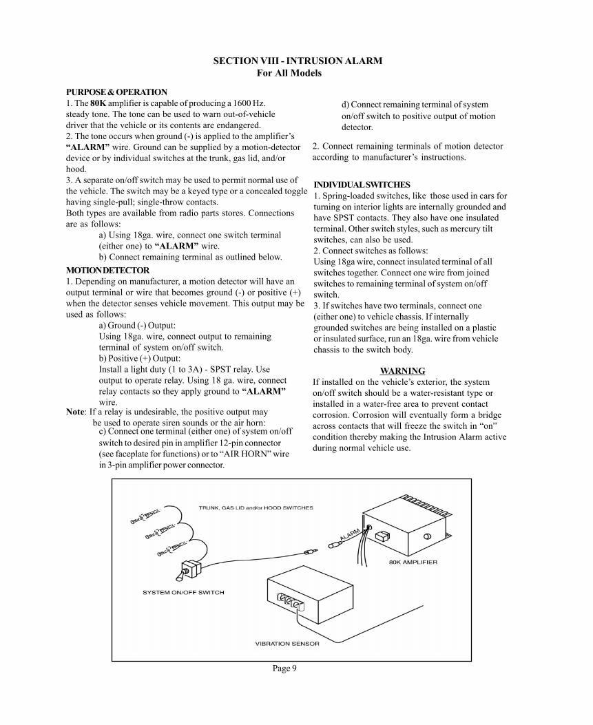
PURPOSE & OPERATION1. The 80K amplifier is capable of producing a 1600 Hz.steady tone. The tone can be used to warn out-of-vehicledriver that the vehicle or its contents are endangered.2. The tone occurs when ground (-) is applied to the amplifier’s“ALARM” wire. Ground can be supplied by a motion-detectordevice or by individual switches at the trunk, gas lid, and/orhood.3. A separate on/off switch may be used to permit normal use ofthe vehicle. The switch may be a keyed type or a concealed togglehaving single-pull; single-throw contacts.Both types are available from radio parts stores. Connectionsare as follows:
a) Using 18ga. wire, connect one switch terminal(either one) to “ALARM” wire.b) Connect remaining terminal as outlined below.
MOTION DETECTOR1. Depending on manufacturer, a motion detector will have anoutput terminal or wire that becomes ground (-) or positive (+)when the detector senses vehicle movement. This output may beused as follows:
a) Ground (-) Output:Using 18ga. wire, connect output to remainingterminal of system on/off switch.b) Positive (+) Output:Install a light duty (1 to 3A) - SPST relay. Useoutput to operate relay. Using 18 ga. wire, connectrelay contacts so they apply ground to “ALARM”wire.
Note: If a relay is undesirable, the positive output may be used to operate siren sounds or the air horn:
Page 9
c) Connect one terminal (either one) of system on/offswitch to desired pin in amplifier 12-pin connector(see faceplate for functions) or to “AIR HORN” wirein 3-pin amplifier power connector.
2. Connect remaining terminals of motion detectoraccording to manufacturer’s instructions.
INDIVIDUAL SWITCHES1. Spring-loaded switches, like those used in cars forturning on interior lights are internally grounded andhave SPST contacts. They also have one insulatedterminal. Other switch styles, such as mercury tiltswitches, can also be used.2. Connect switches as follows:Using 18ga wire, connect insulated terminal of allswitches together. Connect one wire from joinedswitches to remaining terminal of system on/offswitch.3. If switches have two terminals, connect one(either one) to vehicle chassis. If internallygrounded switches are being installed on a plasticor insulated surface, run an 18ga. wire from vehiclechassis to the switch body.
WARNINGIf installed on the vehicle’s exterior, the systemon/off switch should be a water-resistant type orinstalled in a water-free area to prevent contactcorrosion. Corrosion will eventually form a bridgeacross contacts that will freeze the switch in “on”condition thereby making the Intrusion Alarm activeduring normal vehicle use.
d) Connect remaining terminal of systemon/off switch to positive output of motiondetector.

Page 10
SECTION IX - TWO-TONE SYSTEMS For Model 180K
REQUIRED EQUIPMENT1. Control Unit- Any existing 180 system can be used.No modifications or additional switches are needed.2. Amplifiers- Two amplifiers, each housed in a separatecabinet, are required.3. Cables- A UMCO29T is needed for interconnecting thetwo amplifiers. UMCO30K (4 foot or 15 foot long) isneeded for interconnecting both amplifiers with the controlunit.UMCO29K normally supplied with control switches.4. Siren Speakers- At least one speaker must be used witheach amplifier. Two speakers may be used as indicated bydotted lines in drawing.
Note: A speaker having one horn, but two driver units(such as 200 watt speaker), is electrically the same astwo speakers.
AMPLIFIER INSTALLATION1. Install first amplifier as indicated in drawing.2. Set slide switch on bottom of amplifier chassisto match power rating of speakers to be used.3. Install amplifiers with 4 inches maximumbetween cabinets.
PRELIMINARY CONNECTIONS1. Interconnect AIR HORN wires from both 3-pinamplifier connectors using the appropriate connector.2. Interconnect ALARM wires from both amplifiers ifIntrusion Alarm (Section VIII) is desired. If not wantedtape and do not use wire.3. Connect one terminal (either one) of a siren speakerto vehicle chassis (-). Repeat for all other speakers usingsame terminal # of each speaker.4. Connect the BROWN wire from each amplifierconnector to chassis (-).5. If it is desired, wires may be cut in the UMC029T torestrict the number of sounds available in the secondamplifier.
FINAL CONNECTIONSSee drawing.
IMPORTANT: Keep RED amplifier primary wires equalin length. Connect both to a length of 10ga wires.Connectother end directly to battery (+) post or to an appropriatepower distribution terminal. Do not connect to ignitionswitch or ignition - controlled circuit.

SECTION X - TWO-TONE SYSTEMS For Models 280K & 480K
REQUIRED EQUIPMENT1. Control Unit - Any existing 280K or 480Kcontrol unit can be used. No modifications oradditional switches are required.2. Amplifiers - Two amplifiers, each housed in aseparate cabinet, are required.3. Cables - A UMCO30T cable is needed forinterconnecting the two amplifiers. UMCO30K(4’ or 15’ long) is needed for interconnectingboth amplifiers with the control unit.4. Siren Speakers - At least one speaker must beused with each amplifier. Two speakers may beused as indicated by dotted lines in drawing.
Note: A speaker having one horn, but two driverunits (such as a 200 watt speaker), is electricallythe same as two speakers.
AMPLIFIER INSTALLATION1. Install first amplifier as indicated in drawing.2. Set slide switch on bottom of amplifierchassis to match power rating of speakersto be used.3. Install amplifier with 4 inches maximumbetween cabinets.
Page 11
PRELIMINARY CONNECTIONS1. Interconnect AIR HORN wires from both 3 - pinamplifier connectors using the appropriateconnector.2. Intrusion Alarm - See Section VIII.3. Connect one terminal (either one) of one sirenspeaker to vehicle chassis (-). Connect same numberterminal of remaining speakers to vehicle chassis(-).4. Of the two SIREN SPEAKER wires comingfrom the 12-pin control unit pigtail connector,connect either one to vehicle chassis (-), and theother to the speaker.
FINAL CONNECTIONSa) see drawings.
1. The RED primary wire from the added amplifiermust connect directly to the positive (+) battery postor to an appropriate power distribution terminal.2. It is vitally important for proper siren operationthat a 12-ga (minimum) “jumper” be placed across theRED primary wires of each amplifier as indicated.

SECTION XI - GENERAL INFORMATION
AMPLIFIER SPECIFICATIONSStandby Current DrainCurrent Drain During PAMaximum siren current Drain @ 200 WattsSiren Output (Switch Adjustable)WAIL and YELP FrequenciesHI-LO & HETRO FrequenciesIntrusion Alarm FrequencyAir Horn Mid-FrequencyWAIL Repetition RateYELP Repetition RateHI-LO Repetition RateHETRO Repetition RateAudio Output with One SpeakerAudio DistortionReversed Input PolarityInput Voltage Over 16VdcSpeaker Short CircuitAmplifier Restoration After Shorting
Zero 800 Mils. 15A.58 to 200 Watts500 to 1600 Hz. 625 & 575 Hz. 1600 Hz. 1050 Hz. 11 Per Minute 240 Per Minute 60 Per Minute 900 Per Minute 25 or 50 Watts Less Than 10% Protected Protected Protected Automatic
DETERMINING WIRE SIZE1. It is essential to proper siren and warning lightoperation to use wires large enough to carry theload (amperes). Wires too small will create sirenmalfunctions and reduce warning light brillianceand can easily cause vehicle fires.2. Primary Wire Size - Refers to model number andcorresponding instructions in this Manual.3. Warning Light & Accessory Sizes - Determinewire size by adding current drain (amperes) of alllights or accessories that will be connected to anyone control wire from Unitrol.4. Warning Light Current Drain - Lamps used inwarning lights are frequently rated in terms of “watts”rather than “amperes”. Simply divide watts by vehiclevoltage (13 volts nominal). The result will be amperes.5. Motors & Relays - Most motors used in warninglight bars draw 1 ampere or less. Most relays draw 3amperes or less.6. Keep in mind that wire diameter increases as wiregauge number decreases.
POWER JACK PLUG1. A radar, cord light or any device drawing less than 18amperes can be operated from the power jack in Models280K and 480K. The jack accepts a two-contact “telephone”plug. Use 18ga. (minimum) insulated wire. Observe polarity.
TAPE JACK PLUG1. Recorded messages and music can be played over the PAsystem with Models 280K and 480K. A cord plugs into therecorder’s headphone jack at one end into the tape jack at theother end.2. Only battery-operated recorders can be used. The Unitrolpower jack cannot be used to power the recorder.3. Audio connections may be obtained by using audio plugswith 20-24 gauge wire.
Page 12
INDICATOR LIGHT REPLACEMENT1. Indicator lights in models 280K, 480K andSwitchpak are designed to be replaced as acomplete unit (the light bulb is molded into theindicator light body). The body is secured inplace by barrel pressure. No hardware is usedor required.2. To replace, proceed as follows:
a) Pull control unit chassis forward andde-solder wire from the two lamp terminals.b) Push indicator light from terminal-enduntil body passes through faceplate.c) Reverse process to install replacementlight using care not to overheat lampterminals during soldering.
NOTE : Hi - Lo is deleted in the state of CA. The toneis not recognized as a primary emergency warningtone as per Title 13.

SECTION XII - WARRANTY & TECHNICAL SUPPORT
Page 13
UNITROL products described in this Manual are warranted to be free from defects in material andworkmanship for five years from installation date.Any product found to be faulty will, at the factory’soption after inspection, be replaced or repaired and returned without charge.
The Warranty does not cover any charges which may be incurred for removing a suspected defectiveunit, returning the suspected defective unit to the factory or for installing a replacement unit.
The Warranty does not cover units that have been tampered with or on which unauthorized repairs ormodifications have been made nor does it cover units that have been abused or used beyond limitsstated in specifications.
FIVE-YEAR WARRANTY & LIMITATIONS
TECHNICAL SUPPORT
The easiest way to solve a UNITROL problem is to phone the factory. Outside California call toll-free1-800-854-3375. Inside California, call (714) 871-3336. Our office is open Monday through Friday8:00 AM to 4:30 PM Pacific Standard Time.
We recommend that any suspect unit be returned to the factory for repair whether it is in Warrantyor not. Technicians have constantly updated information and components.
Please include a brief description of the problem along with your name and phone number so we maycontact you in the event bench tests do not reveal the in-vehicle problem.
SAFETY MESSAGE TO OPERATORS OF UNITROL ELECTRONIC SIRENS AND LIGHT/SOUND SYSTEMS
WARNINGThe lives of people depend on your operation ofUNITROL products. It is important to read andfollow all instructions shipped with the products.In addition, listed below are some other importantsafety instructions and precautions you shouldfollow.
Be aware that the use of your visual and audiblesignaling devices does not give you the right to forceyour way through traffic. Your emergency lights,siren, and actions are REQUESTING theright-of-way.
Although your warning system is operating properlyit may not alert everyone. People may not hear, see,or heed your warning signal. You must recognize thisfact and continue driving cautiously.
Situations may occur which obstruct your warningsignal when natural or man-made objects arebetween your vehicle and others, such as when youraise your hood or trunk lid. If these situations occur,be especially careful.
To properly use a light system you must have agood understanding of general vehicle operation,a high proficiency in the use of safety warningequipment and thorough knowledge of State andFederal UNIFORM TRAFFIC CODES.
Qualifications
Sound HazardsYour hearing, and the hearing of others in or closeto your emergency vehicle could be damaged byloud sounds. This can occur from short exposuresto very loud sounds or from longer exposures tomoderately loud sounds. For hearing conservationguidance, refer to Federal, State or localrecommendations. OSHA Standard 1910.95offers guidance on “Permissible Noise Exposure”.
All effective sirens and horns produce loud soundswhich may, in certain situations, cause permanenthearing loss. You should minimize your exposuretimes and wear suitable hearing protection.
Sound LimitationsMaximum sound output will be severely reducedif any objects are in front of the speaker. If yourinstallation has obstructions in front of the speaker,drive even more cautiously.
Frequently inspect the speaker to ensure that it isclear of any obstruction such as mud or snow, whichwill reduce maximum sound output.
Page 14
Signaling Limitations
Driving LimitationsAt the start of your shift, you should ensure that thewarning system is securely attached to the vehicleand operating properly.
If the unique combination of emergency vehicleequipment installed in your vehicle has resultedin the light/siren controls being installed in aposition that does not allow you to operate themby touch only, OPERATE CONTROLS ONLYWHEN VEHICLE IS STOPPED.
If driving conditions require your full attention, youshould avoide operating the light/siren controlswhile the vehicle is in motion.
Continuing EducationFile these instructions in a safe place and referto them periodically. Give a copy of theseinstructions to new recruits and trainees.
Failure to follow these safety precautions mayresult in property damage, serious injury, deathto you, your passengers or to others.

SAFETY MESSAGE TO INSTALLERS OF
ELECTRONIC SIRENS
WARNINGThe lives of people depend on your safe installationand servicing of UNITROL products. It is importantto read and follow all instructions shipped with theproducts. In addition, listed below are some otherimportant safety instructions and precautions youshould follow before installation:
QualificationsTo properly install an electronic siren you musthave a good understanding of automotive electricalprocedures and systems, along with proficiencyin the installation and service of safety warningequipment.
Sound HazardsYour hearing and the hearing of others, in or closeto your emergency vehicle, could be damaged byloud sounds. This can occur from short exposure tovery loud sounds or from longer exposures tomoderately loud sounds. For hearing conservationguidance, refer to federal, state, or localrecommendations. OSHA Standard 1910.95 offersguidance on “Plermissible Noise Exposure”.
All effective sirens and horns produce loud sounds,which may, in certain situations, cause permanenthearing loss.You should minimize your exposuretimes and wear suitable hearing protection.
During InstallationDO NOT connect this system to the vehicle batteryuntil ALL other electrical connections are made,mounting of all components is complete, and youhave verified that no shorts exist.
Be sure the siren amplifier and speaker(s) in yourinstallation have compatible wattage rating.
In order for the electronic siren to function properly,the ground connection must be made to a solid chassiscomponent and not to an insulated point.
Page 15
Sound output will be severely reduced if any objectsare in front of this speaker. If maximum sound outputis required for your application, you should ensurethat the front of the speaker is clear of any obstruction.
Install the speaker(s) in a location which providesmaximum signaling effectiveness and minimizes thesound reaching the vehicle’s occupants.
Installation of two speakers requires wiring speakers inphases.
DO NOT install equipment or route wiring or cord in thedeployment path of an air bag.
Locate the control head so the vehicle, controls, andmicrophone can be operated safely.
When drilling into a vehicle structure, be sure that bothsides of the surface are clear of anything that could bedamaged.
If wiring is shorted to vehicle frame, high currentconductors can cause hazardous sparks resulting inelectrical fires or flying molten metal.
After Installation
After installation, test the electronic siren, speakersystem, and light system to ensure that it is operatingproperly.
Test all vehicle functions, including horn operationand vehicle light systems, to ensure proper operation.
After testing is complete, provide a copy of theseinstructions to the instructional staff and all operatingpersonel.
File these instructions in a safe place and refer to themwhen maintaining and/or reinstalling the product.
Failure to follow all safety precautions andinstructions may result in property damage,serious injury, or death to you or others.