8028 sip doorphone installation and user guide
DESCRIPTION
8028 SIP Doorphone Installation and User GuideTRANSCRIPT
- 2 -
Important Safety Notice
The 8028 SIP Doorphone is designed and tested to comply with EN 60950-1:2006 safety requirements.
When the Doorphone Controller is connected to wiring that exits the building, there is potential risk of lightning induced electrical surges or high voltages from fault conditions. To reduce risk, outdoor wiring should be protected by Earth grounded conduit whenever possible.
If outdoor wiring will be connected to the Doorphone Controller then the power supply provided with the Doorphone Controller must first be connected to a properly Earthed mains supply. Under no circumstances can the Doorphone Controller be disconnected from Earth ground while connected to outdoor wiring.
SupportAlgo is pleased to offer telephone or email support relating to installation issues, applications assistance, or general product inquiries.
Algo Communication Products Ltd.4500 Beedie StreetBurnaby, British ColumbiaCanada, V5J [email protected] [email protected]
Algo products are warranted against defect in workmanship for a period of 12 months after installation not to exceed 18 months from date of manufacture.
FCC ComplianceThis equipment has been tested and found to comply with the limits for a Class B digital device, pursuant to part 15 of the FCC Rules. These limits are designed to provide reasonable protection against interference in a residential installation. This equipment generates, uses, and can radiate radio frequency energy and, if not installed and used in accordance with the instructions, may cause harmful interference to radio communications. However, there is no guarantee that interference will not occur in a particular installation. If this equipment does cause harmful interference to radio or television reception, which can be determined by turning the equipment off and on, the user is encouraged to try to correct the interference by one or more of the following measures: 1) Reorient or relocate the receiving antenna, 2) Increase the separation between the equipment and receiver, 3) Connect the equipment into an outlet on a circuit different from that to which the receiver is connected, or 4) Consult the dealer or an experienced radio/TV technician for help.
- 3 -
Table of ContentsSupport . . . . . . . . . . . . . . . . . . . . . . . . . . . . . . . . . . . . . . . . . . . . . . . . . . 2FCC Compliance . . . . . . . . . . . . . . . . . . . . . . . . . . . . . . . . . . . . . . . . . . . 2Important Safety Notice . . . . . . . . . . . . . . . . . . . . . . . . . . . . . . . . . . . . . . 2
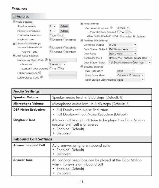
Introduction . . . . . . . . . . . . . . . . . . . . . . . . . . . . . . . . . . . . . . . 4Features . . . . . . . . . . . . . . . . . . . . . . . . . . . . . . . . . . . . . . . . . . . . . . . . . 4
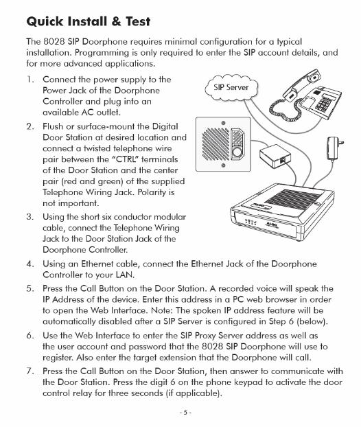
Quick Install & Test . . . . . . . . . . . . . . . . . . . . . . . . . . . . . . . . . 5
Applications . . . . . . . . . . . . . . . . . . . . . . . . . . . . . . . . . . . . . . . 6Typical Applications for Auxiliary Inputs and Outputs . . . . . . . . . . . . . . . . 6
Door or Gate Control Basics. . . . . . . . . . . . . . . . . . . . . . . . . . . 8Door Release . . . . . . . . . . . . . . . . . . . . . . . . . . . . . . . . . . . . . . . . . . . . . 8
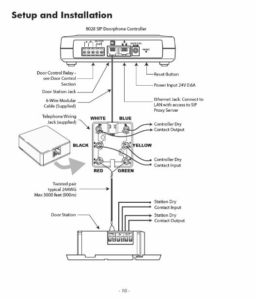
Setup and Installation . . . . . . . . . . . . . . . . . . . . . . . . . . . . . . 10
Programming and Configuration. . . . . . . . . . . . . . . . . . . . . . 11Web Interface Control Panel . . . . . . . . . . . . . . . . . . . . . . . . . . . . . . . . . 11
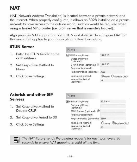
NAT. . . . . . . . . . . . . . . . . . . . . . . . . . . . . . . . . . . . . . . . . . . . . 19STUN Server . . . . . . . . . . . . . . . . . . . . . . . . . . . . . . . . . . . . . . . . . . . . . 19Asterisk and other SIP Servers . . . . . . . . . . . . . . . . . . . . . . . . . . . . . . . . 19
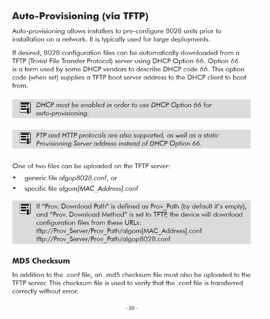
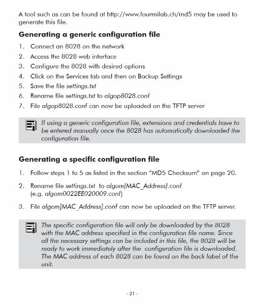
Auto-Provisioning (via TFTP) . . . . . . . . . . . . . . . . . . . . . . . . . 20MD5 Checksum . . . . . . . . . . . . . . . . . . . . . . . . . . . . . . . . . . . . . . . . . . 20Generating a generic configuration file . . . . . . . . . . . . . . . . . . . . . . . . . 21Generating a specific configuration file . . . . . . . . . . . . . . . . . . . . . . . . . 21
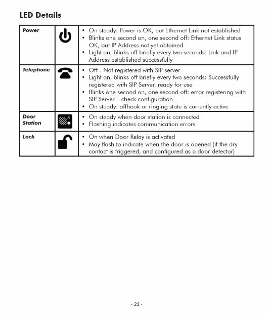
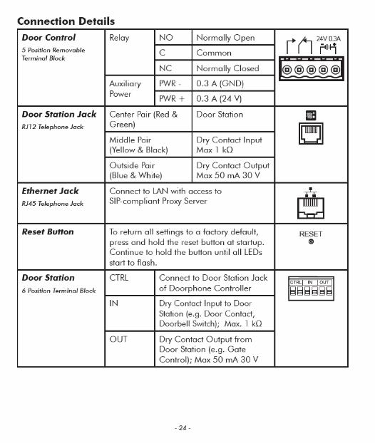
Connections and Lights . . . . . . . . . . . . . . . . . . . . . . . . . . . . . 22Auxiliary Dry Contact Outputs . . . . . . . . . . . . . . . . . . . . . . . . . . . . . . . . 22Auxiliary Dry Contact Inputs . . . . . . . . . . . . . . . . . . . . . . . . . . . . . . . . . 22LED Details . . . . . . . . . . . . . . . . . . . . . . . . . . . . . . . . . . . . . . . . . . . . . . 23Connection Details . . . . . . . . . . . . . . . . . . . . . . . . . . . . . . . . . . . . . . . . 24
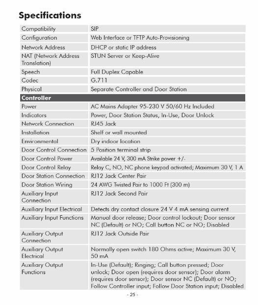
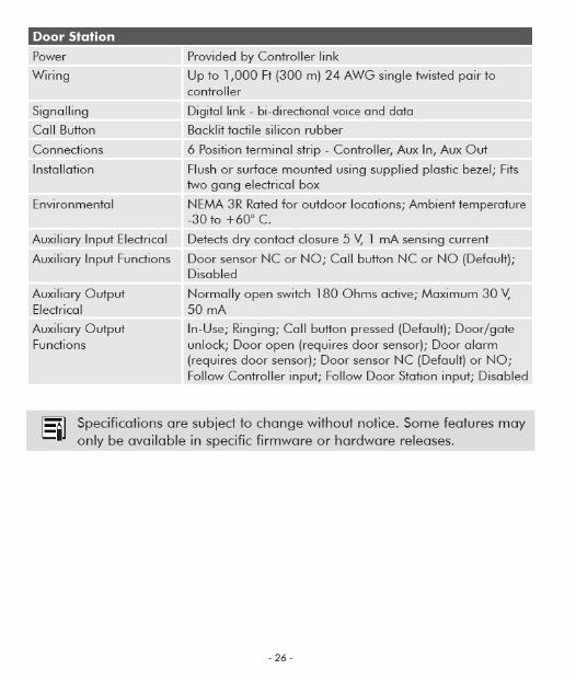
Specifications . . . . . . . . . . . . . . . . . . . . . . . . . . . . . . . . . . . . . 25
Related Doorphone Products . . . . . . . . . . . . . . . . . . . . . . . . . 28
- 6 -
ApplicationsTypical Applications for Auxiliary Inputs and Outputs
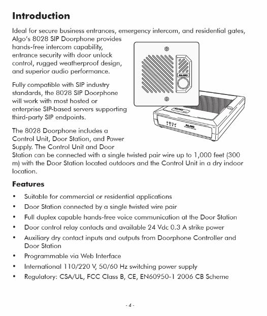
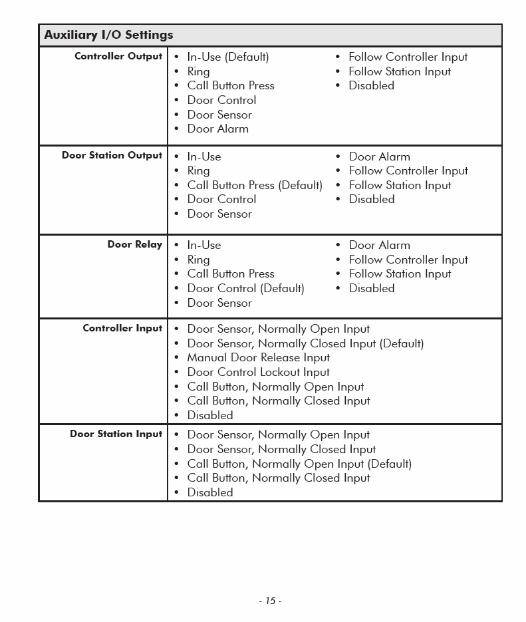
The 8028 architecture and digital link between the Door Station and Controller provides flexible options using the auxiliary inputs and outputs. These are some typical applications:
Cancel Ring When Door Opened
In a residential or warehouse installation it is not uncommon for the door to be answered in person before the phone is answered. Either Door Station or Control Unit inputs can be configured to cancel ring if the door is opened before a call is answered. This requires a normally closed or normally open contact to detect door open.
Trigger Door Bell from Door Station
When the Door Station call button is pressed, either (or both) the Door Station or Control Unit dry contact output can be configured to activate a door bell or auxiliary alerting system in addition to phone ring.
Trigger Door Station from External Button/Event
Either the Control Unit or Door Station can accept a dry contact closure to activate the Doorphone as if the call button had been pressed. This could be an external doorbell button, PIR detector, or some other system.
Cancel Door Open Relay once Door Opened
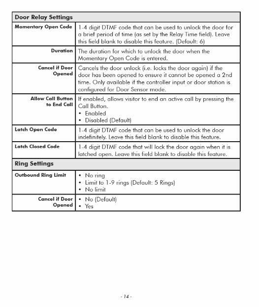
The door opening control can be set for activation (using the `Open Code’) up to 30 seconds (set by the `Relay Time’ setting) to allow sufficient time for entry. For security, the 8028 Doorphone can be configured to cancel Door Opening once the door is opened to prevent “tailgating” by unauthorized personnel.
Unlock Door Indefinitely until Canceled
The door opening control can be set to unlock indefinitely (using the `Latch Open Code’) until canceled (using the `Release Code’) that locks it again. This allows an entrance to be used repeatedly for a period of time without requiring multiple activations of the door control relay.
- 7 -
Anti-Door Tamper
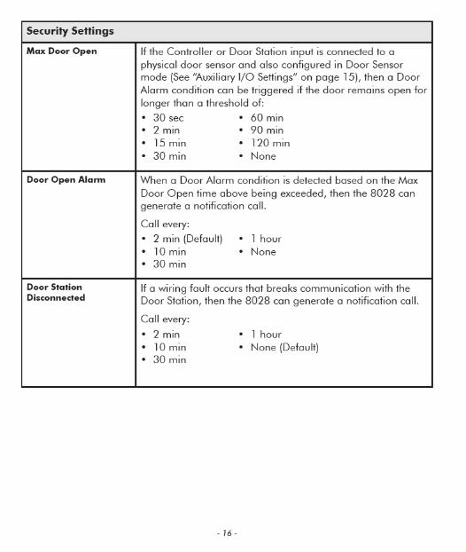
A feature of the 8028 Doorphone is to ring the telephone(s) with a warning alert in the event a door is ajar due to tampering (such as a door blocked open after being legitimately released for a visitor).
In-Use and Ring
Either the Control Unit or Door Station can be configured to provide a dry contact output during ring or in-use for channel selection (typically) of third party video monitoring systems.
- 8 -
Door or Gate Control BasicsControl contacts are provided from the Doorphone Controller and are typically used for door strike activation or gate control. For security, the door control relay is located in the Controller to avoid entry by tampering. The Door Station dry contact output (OUT) may be configured for ‘low security’ gate control requiring a low current dry contact.
Door Release
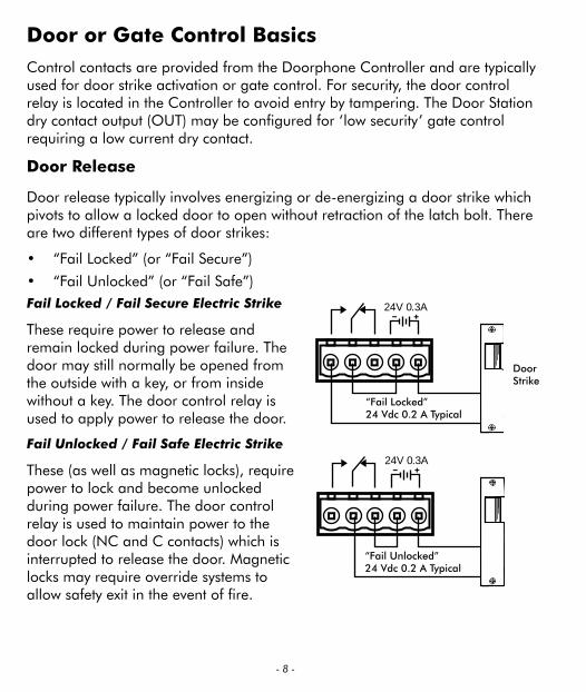
Door release typically involves energizing or de-energizing a door strike which pivots to allow a locked door to open without retraction of the latch bolt. There are two different types of door strikes:
• “Fail Locked” (or “Fail Secure”)
• “Fail Unlocked” (or “Fail Safe”)
24V 0.3A
DoorStrike
“Fail Locked”24 Vdc 0.2 A Typical
24V 0.3A
“Fail Unlocked”24 Vdc 0.2 A Typical
Fail Locked / Fail Secure Electric Strike
These require power to release and remain locked during power failure. The door may still normally be opened from the outside with a key, or from inside without a key. The door control relay is used to apply power to release the door.
Fail Unlocked / Fail Safe Electric Strike
These (as well as magnetic locks), require power to lock and become unlocked during power failure. The door control relay is used to maintain power to the door lock (NC and C contacts) which is interrupted to release the door. Magnetic locks may require override systems to allow safety exit in the event of fire.
- 11 -
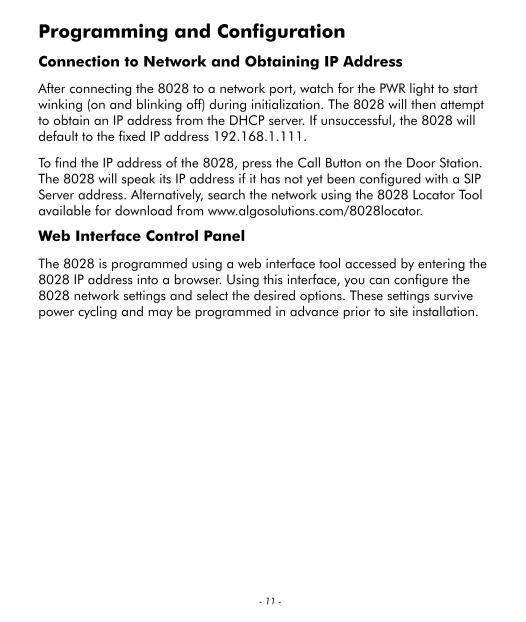
Programming and Configuration
Connection to Network and Obtaining IP Address
After connecting the 8028 to a network port, watch for the PWR light to start winking (on and blinking off) during initialization. The 8028 will then attempt to obtain an IP address from the DHCP server. If unsuccessful, the 8028 will default to the fixed IP address 192.168.1.111.
To find the IP address of the 8028, press the Call Button on the Door Station. The 8028 will speak its IP address if it has not yet been configured with a SIP Server address. Alternatively, search the network using the 8028 Locator Tool available for download from www.algosolutions.com/8028locator.
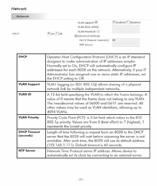
Web Interface Control Panel
The 8028 is programmed using a web interface tool accessed by entering the 8028 IP address into a browser. Using this interface, you can configure the 8028 network settings and select the desired options. These settings survive power cycling and may be programmed in advance prior to site installation.

- 27 -
Note: This page left intentionally blank.