77809 cover.cdr:coreldraw - manuals.gogenielift.commanuals.gogenielift.com/parts and service...
TRANSCRIPT

Service Manual
Z-45/25Z-45/25JIC Power
Part No. 77809
Rev C2
August 2005
Serial Number Range
Deutz models: from 21180 to 23040Ford models: from 21180 to 23189Perkins models: from 21180 to 23008

Z-45/25 • Z-45/25J Part No. 77809
March 2005
ii
Introduction
Important
Read, understand and obey the safety rules andoperating instructions in the Genie Z-45/25 andGenie Z-45/25J Operator's Manual beforeattempting any maintenance or repair procedure.
This manual provides detailed scheduledmaintenance information for the machine ownerand user. It also provides troubleshooting faultcodes and repair procedures for qualified serviceprofessionals.
Basic mechanical, hydraulic and electrical skillsare required to perform most procedures.However, several procedures require specializedskills, tools, lifting equipment and a suitableworkshop. In these instances, we stronglyrecommend that maintenance and repair beperformed at an authorized Genie dealer servicecenter.
Technical Publications
Genie Industries has endeavored to deliver thehighest degree of accuracy possible. However,continuous improvement of our products is a Geniepolicy. Therefore, product specifications aresubject to change without notice.
Readers are encouraged to notify Genie of errorsand send in suggestions for improvement. Allcommunications will be carefully considered forfuture printings of this and all other manuals.
Contact Us:
http://www.genieindustries.come-mail: [email protected]
Serial Number Information
Genie Industries offers the following ServiceManuals for these models:
Title Part No.
Z-45/25 and Z-45/25J Service Manual ................. 52709From serial number 9998 to 21179
Z-45/25 and Z-45/25J Service Manual ................. 77809Deutz models: from 21180 to 23040Ford models: from 21180 to 23189Perkins models: from 21180 to 23008
Z-45/25 and Z-45/25J Service Manual ...............107846Deutz models: from 23041 to 34010Ford models: from 23190 to 34010Perkins models: from 23009 to 34010All models: from A34011 to A47000All models: from B101
Z-45/25 and Z-45/25J Service Manual ...............219418From serial number 13A-47001
Copyright © 2003 by Genie Industries
77809 Rev C March 2005
"Genie" and "Z" are registered trademarks ofGenie Industries in the USA and many othercountries.
Printed on recycled paper
Printed in U.S.A.

Part No. 77809 Genie Z-45/25 and Genie Z-45/25J
March 2005
iii
Safety Rules
Section 1 • Safety Rules
DangerFailure to obey the instructions and safety rules inthis manual, and the Genie Z-45/25 andGenie Z-45/25J Operator's Manual will result indeath or serious injury.
Many of the hazards identified in the operator'smanual are also safety hazards when maintenanceand repair procedures are performed.
Do Not Perform MaintenanceUnless:
You are trained and qualified to performmaintenance on this machine.
You read, understand and obey:- manufacturer’s instructions and safety rules- employer’s safety rules and worksite
regulations- applicable governmental regulations
You have the appropriate tools, liftingequipment and a suitable workshop.
Genie Z-45/25 and Genie Z-45/25J Part No. 77809
March 2005
SAFETY RULES
iv
Section 1 • Safety Rules
Personal SafetyAny person working on or around a machine mustbe aware of all known safety hazards. Personalsafety and the continued safe operation of themachine should be your top priority.
Read each procedure thoroughly. Thismanual and the decals on the machineuse signal words to identify the following:
Safety alert symbol—used to alertpersonnel to potential personalinjury hazards. Obey all safetymessages that follow this symbolto avoid possible injury or death.
Used to indicate the presence ofan imminently hazardous situationwhich, if not avoided, will result indeath or serious injury.
Used to indicate the presence of apotentially hazardous situationwhich, if not avoided, could resultin death or serious injury.
With safety alert symbol—used toindicate the presence of apotentially hazardous situationwhich, if not avoided, may result inminor or moderate injury.
Without safety alert symbol—usedto indicate the presence of apotentially hazardous situationwhich, if not avoided, may result inproperty damage.
Used to indicate operation ormaintenance information.
Be sure to wear protective eye wear andother protective clothing if the situationwarrants it.
Be aware of potential crushing hazardssuch as moving parts, free swinging orunsecured components when lifting or
placing loads. Always wear approved steel-toedshoes.
Workplace SafetyBe sure to keep sparks, flames andlighted tobacco away from flammableand combustible materials like battery
gases and engine fuels. Always have an approvedfire extinguisher within easy reach.
Be sure that all tools and working areasare properly maintained and ready foruse. Keep work surfaces clean and free
of debris that could get into machine componentsand cause damage.
Be sure any forklift, overhead crane orother lifting or supporting device is fullycapable of supporting and stabilizing the
weight to be lifted. Use only chains or straps thatare in good condition and of ample capacity.
Be sure that fasteners intended for onetime use (i.e., cotter pins and self-lockingnuts) are not reused. These components
may fail if they are used a second time.
Be sure to properly dispose of old oil orother fluids. Use an approved container.Please be environmentally safe.
Be sure that your workshop or work areais properly ventilated and well lit.
Part No. 77809 Z-45/25 • Z-45/25J
August 2005
Table of Contents
v
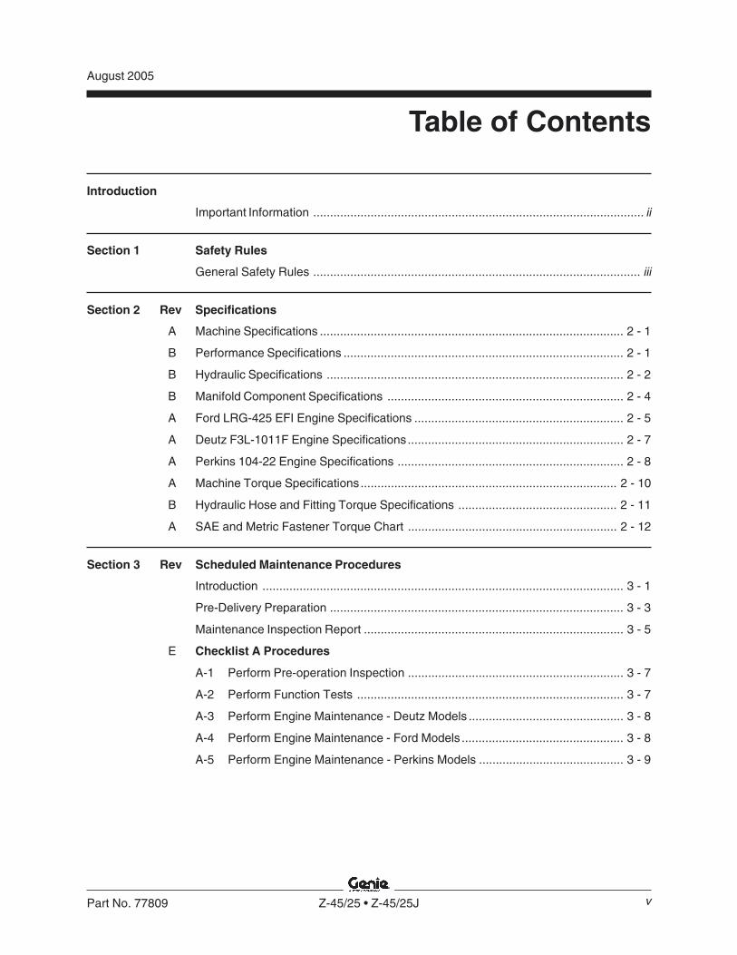
Introduction
Important Information .................................................................................................. ii
Section 1 Safety Rules
General Safety Rules ................................................................................................. iii
Section 2 Rev Specifications
A Machine Specifications .......................................................................................... 2 - 1
B Performance Specifications ................................................................................... 2 - 1
B Hydraulic Specifications ........................................................................................ 2 - 2
B Manifold Component Specifications ...................................................................... 2 - 4
A Ford LRG-425 EFI Engine Specifications .............................................................. 2 - 5
A Deutz F3L-1011F Engine Specifications................................................................ 2 - 7
A Perkins 104-22 Engine Specifications ................................................................... 2 - 8
A Machine Torque Specifications............................................................................ 2 - 10
B Hydraulic Hose and Fitting Torque Specifications ............................................... 2 - 11
A SAE and Metric Fastener Torque Chart .............................................................. 2 - 12
Section 3 Rev Scheduled Maintenance Procedures
Introduction ........................................................................................................... 3 - 1
Pre-Delivery Preparation ....................................................................................... 3 - 3
Maintenance Inspection Report ............................................................................. 3 - 5
E Checklist A Procedures
A-1 Perform Pre-operation Inspection ................................................................ 3 - 7
A-2 Perform Function Tests ............................................................................... 3 - 7
A-3 Perform Engine Maintenance - Deutz Models .............................................. 3 - 8
A-4 Perform Engine Maintenance - Ford Models ................................................ 3 - 8
A-5 Perform Engine Maintenance - Perkins Models ........................................... 3 - 9

Z-45/25 • Z-45/25J Part No. 77809
June 2005
TABLE OF CONTENTS
vi
Section 3 Rev Scheduled Maintenance Procedures, continued
A-6 Check the High Pressure Hydraulic Filter Condition Indicator ...................... 3 - 9
A-7 Test the Oscillate Axle (if equipped) .......................................................... 3 - 10
A-8 Perform 30 Day Service ............................................................................. 3 - 10
A-9 Perform Engine Maintenance - Ford and Perkins Models .......................... 3 - 11
A-10 Replace the Fuel Filters - Ford Models ...................................................... 3 - 11
A-11 Inspect the Fuel Filter/Water Separator - Diesel Models ............................ 3 - 13
A-12 Check and Adjust the Engine RPM - Perkins Models ................................ 3 - 15
A-13 Grease the Turntable Rotation Bearing and Rotate Gear .......................... 3 - 16
A-14 Perform Engine Maintenance - Ford Models .............................................. 3 - 16
A-15 Perform Engine Maintenance - Perkins Models ......................................... 3 - 17
D Checklist B Procedures
B-1 Inspect the Battery ..................................................................................... 3 - 18
B-2 Inspect the Electrical Wiring ....................................................................... 3 - 18
B-3 Test the Key Switch ................................................................................... 3 - 19
B-4 Perform Engine Maintenance - Ford Models .............................................. 3 - 20
B-5 Check the Exhaust System........................................................................ 3 - 20
B-6 Check the Oil Cooler and Cooling Fins - Deutz Models ............................. 3 - 21
B-7 Check the Lug Nut Torque (including the tires and wheels) ....................... 3 - 22
B-8 Confirm the Proper Brake Configuration .................................................... 3 - 22
B-9 Check the Oil Level in the Drive Hubs ....................................................... 3 - 23
B-10 Check and Adjust the Engine RPM - Ford and Deutz Models .................... 3 - 23
B-11 Test the Ground Control Override .............................................................. 3 - 24

Part No. 77809 Z-45/25 • Z-45/25J
June 2005
TABLE OF CONTENTS
vii
Section 3 Rev Scheduled Maintenance Procedures, continued
B-12 Check the Directional Valve Linkage ......................................................... 3 - 25
B-13 Test the Platform Self-leveling ................................................................... 3 - 25
B-14 Test the Engine Idle Select ........................................................................ 3 - 26
B-15 Test the Fuel Select Operation - Ford Models ........................................... 3 - 26
B-16 Test the Drive Brakes ................................................................................ 3 - 27
B-17 Test the Drive Speed - Stowed Position .................................................... 3 - 28
B-18 Test the Drive Speed - Raised or Extended Position ................................. 3 - 28
B-19 Test the Alarm Package (if equipped) ........................................................ 3 - 29
B-20 Perform Hydraulic Oil Analysis .................................................................. 3 - 30
B-21 Replace the Fuel Filter/Water Separator Element - Perkins Models .......... 3 - 31
B-22 Replace the Fuel Filter Element - Perkins Models ..................................... 3 - 33
B-23 Perform Engine Maintenance - Deutz Models ............................................ 3 - 34
B-24 Perform Engine Maintenance - Ford Models .............................................. 3 - 35
B-25 Perform Engine Maintenance - Perkins Models ......................................... 3 - 35
C Checklist C Procedures
C-1 Perform Engine Maintenance - Deutz Models ............................................ 3 - 36
C-2 Grease the Platform Overload Mechanism (if equipped) ........................... 3 - 36
C-3 Test the Platform Overload Mechanism (if equipped) ................................ 3 - 37
C-4 Perform Engine Maintenance - Perkins Models ......................................... 3 - 39
C-5 Perform Engine Maintenance - Ford Models .............................................. 3 - 39

Z-45/25 • Z-45/25J Part No. 77809
June 2005
Section 3 Rev Scheduled Maintenance Procedures, continued
D Checklist D Procedures
D-1 Check the Boom Wear Pads ..................................................................... 3 - 40
D-2 Check the Turntable Rotation Bearing Bolts .............................................. 3 - 40
D-3 Check the Free-wheel Configuration .......................................................... 3 - 42
D-4 Replace the Drive Hub Oil ......................................................................... 3 - 43
D-5 Check and Adjust the Air/LPG Mixture - Ford Models ................................ 3 - 44
D-6 Perform Engine Maintenance - Deutz Models ............................................ 3 - 45
D-7 Inspect for Turntable Bearing Wear ........................................................... 3 - 45
D-8 Calibrate the Platform Overload System (if equipped) ............................... 3 - 47
D-9 Replace the Hydraulic Filters ..................................................................... 3 - 48
B Checklist E Procedures
E-1 Test or Replace the Hydraulic Oil .............................................................. 3 - 50
E-2 Change the Fuel Hoses - Ford Models ...................................................... 3 - 52
E-3 Perform Engine Maintenance - Deutz Models ............................................ 3 - 53
E-4 Grease the Steer Axle Wheel Bearings, 2WD Models ............................... 3 - 53
Section 4 Rev Repair Procedures
Introduction ........................................................................................................... 4 - 1
C Platform Controls
1-1 ALC-500 Circuit Board ................................................................................. 4 - 2
1-2 Joysticks ...................................................................................................... 4 - 3
A Platform Components
2-1 Platform Leveling Slave Cylinder ................................................................. 4 - 7
2-2 Platform Rotator ........................................................................................... 4 - 8
viii
TABLE OF CONTENTS

Part No. 77809 Genie Z-45/25 and Genie Z-45/25J
March 2005
Section 4 Rev Repair Procedures, continued
B Jib Boom Components, Z-45/25J
3-1 Jib Boom.................................................................................................... 4 - 10
3-2 Jib Boom Lift Cylinder ................................................................................ 4 - 11
A Primary Boom Components
4-1 Cable Track ............................................................................................... 4 - 12
4-2 Primary Boom ............................................................................................ 4 - 16
4-3 Primary Boom Lift Cylinder ........................................................................ 4 - 18
4-4 Primary Boom Extension Cylinder ............................................................. 4 - 19
4-5 Platform Leveling Master Cylinder ............................................................. 4 - 20
A Secondary Boom Components
5-1 Secondary Boom ....................................................................................... 4 - 22
5-2 Secondary Boom Lift Cylinders .................................................................. 4 - 27
B Engines
6-1 RPM Adjustment - Ford and Deutz Models ................................................ 4 - 28
6-2 RPM Adjustment - Perkins Models ............................................................ 4 - 28
6-3 Flex Plate ................................................................................................... 4 - 28
6-4 Engine Fault Codes - Ford Models ............................................................ 4 - 29
A Hydraulic Pumps
7-1 Lift/Steer Pump .......................................................................................... 4 - 31
7-2 Drive Pump ................................................................................................ 4 - 32
ix
TABLE OF CONTENTS

Genie Z-45/25 and Genie Z-45/25J Part No. 77809
March 2005
TABLE OF CONTENTS
Section 4 Rev Repair Procedures, continued
B Manifolds
8-1 Function Manifold Components (before serial number 22050) ................... 4 - 34
8-2 Valve Adjustments - Function Manifold (before serial number 22050) ....... 4 - 38
8-3 Function Manifold Components (after serial number 22049) ...................... 4 - 40
8-4 Valve Adjustments - Function Manifold (after serial number 22049) .......... 4 - 44
8-5 Jib Boom / Platform Rotate Manifold Components(before serial number 22050) ..................................................................... 4 - 45
8-6 Jib Boom / Platform Rotate Manifold Components(after serial number 22049) ........................................................................ 4 - 46
8-7 Turntable Rotation Manifold Components .................................................. 4 - 47
8-8 Directional Valve Manifold Components .................................................... 4 - 48
8-9 Drive Manifold Components, 2WD ............................................................. 4 - 50
8-10 Valve Adjustments, 2WD Drive Manifold ................................................... 4 - 52
8-11 Drive Manifold Components, 4WD ............................................................. 4 - 54
8-12 Valve Adjustments, 4WD Drive Manifold ................................................... 4 - 56
. A Turntable Rotation Components
9-1 Turntable Rotation Assembly ..................................................................... 4 - 57
B Axle Components
10-1 Hub and Bearings, 2WD Models ................................................................ 4 - 58
10-2 Oscillate Lock-out Cylinders ...................................................................... 4 - 59
Section 5 Rev Fault Codes
Introduction ........................................................................................................... 5 - 1
B Fault Codes - Control System ............................................................................... 5 - 2
B Fault Codes - Ford Models .................................................................................... 5 - 6
x

Part No. 77809 Genie Z-45/25 and Genie Z-45/25J
March 2005
TABLE OF CONTENTS
Section 6 Rev Schematics
Introduction ........................................................................................................... 6 - 1
B Electrical Symbols Legend .................................................................................... 6 - 2
B Hydraulic Symbols Legend .................................................................................... 6 - 3
Ford LRG-425 EFI models
A Engine Harness (before serial number 22050) ...................................................... 6 - 5
A Engine Harness (after serial number 22049) ......................................................... 6 - 6
A Electrical Schematic, Z-45/25 (before serial number 22050) ................................. 6 - 7
A Electrical Schematic, Z-45/25 (after serial number 22049) .................................... 6 - 9
A Ground Control Box Terminal Strip Wiring Diagram, Z-45/25(before serial number 22050) .............................................................................. 6 - 11
A Ground Control Box Switch Panel Wiring Diagram, Z-45/25(before serial number 22050) .............................................................................. 6 - 12
A Ground Control Box Terminal Strip Wiring Diagram, Z-45/25(after serial number 22049) ................................................................................. 6 - 13
A Ground Control Box Switch Panel Wiring Diagram, Z-45/25(after serial number 22049) ................................................................................. 6 - 14
A Platform Control Box Terminal Strip Wiring Diagram, Z-45/25(before serial number 22050) .............................................................................. 6 - 15
A Platform Control Box Switch Panel Wiring Diagram, Z-45/25(before serial number 22050) .............................................................................. 6 - 16
A Platform Control Box Terminal Strip Wiring Diagram, Z-45/25(after serial number 22049) ................................................................................. 6 - 17
A Platform Control Box Switch Panel Wiring Diagram, Z-45/25(after serial number 22049) ................................................................................. 6 - 18
xi

Genie Z-45/25 and Genie Z-45/25J Part No. 77809
March 2005
TABLE OF CONTENTS
xii
Section 6 Rev Schematics, continued
Ford LRG-425 EFI models, continued
A Electrical Schematic, Z-45/25J (before serial number 22050) ............................. 6 - 19
A Electrical Schematic, Z-45/25J (after serial number 22049) ................................ 6 - 21
A Ground Control Box Terminal Strip Wiring Diagram, Z-45/25J(before serial number 22050) .............................................................................. 6 - 23
A Ground Control Box Switch Panel Wiring Diagram, Z-45/25J(before serial number 22050) .............................................................................. 6 - 24
A Ground Control Box Terminal Strip Wiring Diagram, Z-45/25J(after serial number 22049) ................................................................................. 6 - 25
A Ground Control Box Switch Panel Wiring Diagram, Z-45/25J(after serial number 22049) ................................................................................. 6 - 26
A Platform Control Box Terminal Strip Wiring Diagram, Z-45/25J(before serial number 22050) .............................................................................. 6 - 27
A Platform Control Box Switch Panel Wiring Diagram, Z-45/25J(before serial number 22050) .............................................................................. 6 - 28
A Platform Control Box Terminal Strip Wiring Diagram, Z-45/25J(after serial number 22049) ................................................................................. 6 - 29
A Platform Control Box Switch Panel Wiring Diagram, Z-45/25J(after serial number 22049) ................................................................................. 6 - 30

Part No. 77809 Genie Z-45/25 and Genie Z-45/25J
March 2005
Section 6 Rev Schematics, continued
Deutz F3L-1011F models
A Electrical Schematic, Z-45/25 (before serial number 22050) ............................... 6 - 31
A Electrical Schematic, Z-45/25 (after serial number 22049) .................................. 6 - 33
A Electrical Schematic, Z-45/25 (after serial number 22049)CE models ........................................................................................................... 6 - 35
A Ground Control Box Terminal Strip Wiring Diagram, Z-45/25(before serial number 22050) .............................................................................. 6 - 37
A Ground Control Box Switch Panel Wiring Diagram, Z-45/25(before serial number 22050) .............................................................................. 6 - 38
A Ground Control Box Terminal Strip Wiring Diagram, Z-45/25(after serial number 22049) ................................................................................. 6 - 39
A Ground Control Box Switch Panel Wiring Diagram, Z-45/25(after serial number 22049) ................................................................................. 6 - 40
A Ground Control Box Terminal Strip Wiring Diagram, Z-45/25CE Models (after serial number 22049) ............................................................... 6 - 41
A Ground Control Box Switch Panel Wiring Diagram, Z-45/25CE Models (after serial number 22049) ............................................................... 6 - 42
A Platform Control Box Terminal Strip Wiring Diagram, Z-45/25(before serial number 22050) .............................................................................. 6 - 43
A Platform Control Box Switch Panel Wiring Diagram, Z-45/25(before serial number 22050) .............................................................................. 6 - 44
A Platform Control Box Terminal Strip Wiring Diagram, Z-45/25(after serial number 22049) ................................................................................. 6 - 45
A Platform Control Box Switch Panel Wiring Diagram, Z-45/25(after serial number 22049) ................................................................................. 6 - 46
A Electrical Schematic, Z-45/25J (before serial number 22050) ............................. 6 - 47
A Electrical Schematic, Z-45/25J (after serial number 22049) ................................ 6 - 49
A Electrical Schematic, Z-45/25J (after serial number 22049)CE models ........................................................................................................... 6 - 51
TABLE OF CONTENTS
xiii

Genie Z-45/25 and Genie Z-45/25J Part No. 77809
March 2005
Section 6 Rev Schematics, continued
Deutz F3L-1011F models, continued
A Ground Control Box Terminal Strip Wiring Diagram, Z-45/25J(before serial number 22050) .............................................................................. 6 - 53
A Ground Control Box Switch Panel Wiring Diagram, Z-45/25J(before serial number 22050) .............................................................................. 6 - 54
A Ground Control Box Terminal Strip Wiring Diagram, Z-45/25J(after serial number 22049) ................................................................................. 6 - 55
A Ground Control Box Switch Panel Wiring Diagram, Z-45/25J(after serial number 22049) ................................................................................. 6 - 56
A Ground Control Box Terminal Strip Wiring Diagram, Z-45/25JCE Models (after serial number 22049) ............................................................... 6 - 57
A Ground Control Box Switch Panel Wiring Diagram, Z-45/25JCE Models (after serial number 22049) ............................................................... 6 - 58
A Platform Control Box Terminal Strip Wiring Diagram, Z-45/25J(before serial number 22050) .............................................................................. 6 - 59
A Platform Control Box Switch Panel Wiring Diagram, Z-45/25J(before serial number 22050) .............................................................................. 6 - 60
A Platform Control Box Terminal Strip Wiring Diagram, Z-45/25J(after serial number 22049) ................................................................................. 6 - 61
A Platform Control Box Switch Panel Wiring Diagram, Z-45/25J(after serial number 22049) ................................................................................. 6 - 62
TABLE OF CONTENTS
xiv
Part No. 77809 Genie Z-45/25 and Genie Z-45/25J
March 2005
TABLE OF CONTENTS
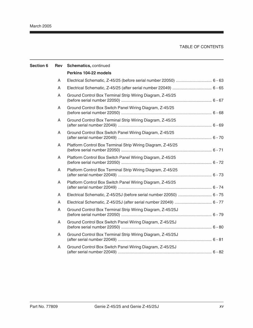
Section 6 Rev Schematics, continued
Perkins 104-22 models
A Electrical Schematic, Z-45/25 (before serial number 22050) ............................... 6 - 63
A Electrical Schematic, Z-45/25 (after serial number 22049) .................................. 6 - 65
A Ground Control Box Terminal Strip Wiring Diagram, Z-45/25(before serial number 22050) .............................................................................. 6 - 67
A Ground Control Box Switch Panel Wiring Diagram, Z-45/25(before serial number 22050) .............................................................................. 6 - 68
A Ground Control Box Terminal Strip Wiring Diagram, Z-45/25(after serial number 22049) ................................................................................. 6 - 69
A Ground Control Box Switch Panel Wiring Diagram, Z-45/25(after serial number 22049) ................................................................................. 6 - 70
A Platform Control Box Terminal Strip Wiring Diagram, Z-45/25(before serial number 22050) .............................................................................. 6 - 71
A Platform Control Box Switch Panel Wiring Diagram, Z-45/25(before serial number 22050) .............................................................................. 6 - 72
A Platform Control Box Terminal Strip Wiring Diagram, Z-45/25(after serial number 22049) ................................................................................. 6 - 73
A Platform Control Box Switch Panel Wiring Diagram, Z-45/25(after serial number 22049) ................................................................................. 6 - 74
A Electrical Schematic, Z-45/25J (before serial number 22050) ............................. 6 - 75
A Electrical Schematic, Z-45/25J (after serial number 22049) ................................ 6 - 77
A Ground Control Box Terminal Strip Wiring Diagram, Z-45/25J(before serial number 22050) .............................................................................. 6 - 79
A Ground Control Box Switch Panel Wiring Diagram, Z-45/25J(before serial number 22050) .............................................................................. 6 - 80
A Ground Control Box Terminal Strip Wiring Diagram, Z-45/25J(after serial number 22049) ................................................................................. 6 - 81
A Ground Control Box Switch Panel Wiring Diagram, Z-45/25J(after serial number 22049) ................................................................................. 6 - 82
xv

Genie Z-45/25 and Genie Z-45/25J Part No. 77809
March 2005
TABLE OF CONTENTS
Section 6 Rev Schematics, continued
Perkins 104-22 models, continued
A Platform Control Box Terminal Strip Wiring Diagram, Z-45/25J(before serial number 22050) .............................................................................. 6 - 83
A Platform Control Box Switch Panel Wiring Diagram, Z-45/25J(before serial number 22050) .............................................................................. 6 - 84
A Platform Control Box Terminal Strip Wiring Diagram, Z-45/25J(after serial number 22049) ................................................................................. 6 - 85
A Platform Control Box Switch Panel Wiring Diagram, Z-45/25J(after serial number 22049) ................................................................................. 6 - 86
Hydraulic Schematics
A Hydraulic Schematic, 2WD Models (before serial number 22050) ....................... 6 - 87
B Hydraulic Schematic, 2WD Models (after serial number 22049) .......................... 6 - 88
A Hydraulic Schematic, 4WD Models (before serial number 22050) ....................... 6 - 89
B Hydraulic Schematic, 4WD Models (after serial number 22049) .......................... 6 - 90
xvi

Part No. 77809 Genie Z-45/25 and Genie Z-45/25J 2 - 1
Section 2 • SpecificationsMarch 2005
REV B Specifications
Machine Specifications
Tires and wheels Rough terrain Industrial
Wheel lugs, 4WD 9 @ 5/8 -18
Wheel lugs, 2WDFront 9 @ 5/8 -18 9 @ 5/8 -18Rear 9 @ 5/8 -18 9 @ 5/8 -18
Lug nut torque, dry 125 ft-lbs 125 ft-lbs169.5 Nm 169.5 Nm
Lug nut torque, lubricated 94 ft-lbs 94 ft-lbs127.4 Nm 127.4 Nm
Tire ply rating 14 Tread 8Sidewall 6
Tire contact area 59 sq in 43.5 sq in149.9 sq cm 280 sq cm
Overall tire diameter 35.8 in 28 in90.9 cm 71 cm
Tire pressure (air filled tires) 45 psi 100 psi3.1 bar 6.9 bar
Fluid capacities
LPG tank 33.5 pounds15.2 kg
Hydraulic tank 24 gallons91 liters
Hydraulic system 30 gallons(including tank) 113.6 liters
Drive hubs 17 fl oz0.5 liters
For operational specifications, refer to theOperator's Manual.
Performance Specifications
Drive speed, maximum
Stowed position 4.8 mph7.7 km/h
40 ft/5.7 sec12.2 m/5.7 sec
Raised or extended position 0.3 mph0.5 km/h
40 ft/45 sec12.2 m/45 sec
Braking distance, maximum
High range on paved surface 3 to 6 ft0.9 to 1.8 m
Boom function speeds, maximumfrom platform controls
Jib boom up, Z-45/25J 28 to 32 seconds
Jib boom down, Z-45/25J 16 to 20 seconds
Primary boom up 24 to 28 seconds
Primary boom down 24 to 28 seconds
Secondary boom up 24 to 28 seconds
Secondary boom down 38 to 42 seconds
Primary boom extend 14 to 18 seconds
Primary boom retract 16 to 20 seconds
Turntable rotate, 359° 62 to 68 secondsprimary boom retracted
Platform rotate, 180° 5 to 7 secondsZ-45/25
Platform rotate, 160° 5 to 7 secondsZ-45/25J
Continuous improvement of our products is aGenie policy. Product specifications aresubject to change without notice.

2 - 2 Genie Z-45/25 and Genie Z-45/25J Part No. 77809
Section 2 • Specifications March 2005
REV BSPECIFICATIONS
Hydraulic Specifications
Hydraulic Oil Specifications
Hydraulic oil type Chevron Rykon MV equivalentISO viscosity grade Multi-viscosityViscosity index 200
Cleanliness level, minimum 15/13
Water content, maximum 200 ppm
Chevron Rykon MV oil is fully compatible andmixable with Shell Donax TG (Dexron III) oils.Genie specifications require hydraulic oils which aredesigned to give maximum protection to hydraulicsystems, have the ability to perform over a widetemperature range, and have a minimum viscosity indexrating of 150. They should provide excellent antiwear,oxidation, corrosion inhibition, seal conditioning, andfoam and aeration suppression properties.
Optional fluids
Biodegradable Petro Canada Premium ECO 46Statoil Hydra Way Bio Pa 32
BP Biohyd SE-S
Fire resistant UCON Hydrolube HP-5046Quintolubric 822
Mineral based Shell Tellus T32Shell Tellus T46
Chevron Aviation A
Use Chevron Aviation A hydraulicoil when in ambient temperaturesconsistently below 0°F / -18°C.
Use Shell Tellus T46 hydraulic oilwhen oil temperatures consistentlyexceed 205°F / 96°C.
Genie specifications requireadditional equipment and specialinstallation instructions for theapproved optional fluids. Consultthe Genie Industries ServiceDepartment before use.
Drive pump
Type: bi-directional, variabledisplacement piston pump
Flow rate @ 2500 rpm 30.3 gpm(before serial number 22050) 114.7 L/min
Flow rate @ 2500 rpm 32 gpm(after serial number 22049) 121 L/min
Drive pressure, maximum 3500 psi(before serial number 22050) 241.3 bar
Drive pressure, maximum 3750 psi(after serial number 22049) 259 bar
Charge pump
Type: gerotor
Displacement 0.85 cu in(before serial number 22050) 13.9 cc
Displacement 0.84 cu in(after serial number 22049) 13.76 cc
Flow rate @ 2500 rpm 9.2 gpm(before serial number 22050) 34.8 L/min
Flow rate @ 2500 rpm 9.1 gpm(after serial number 22049) 34.4 L/min
Charge pressure @ 2500 rpm 250 psi(before serial number 22050) 17.2 bar
Charge pressure @ 2500 rpm 315 psi(after serial number 22049) 21.7 bar
Function pump
Type: gear, pressure balanced
Displacement 0.67 cu in11 cc
Flow rate @ 2500 rpm 7.25 gpm27.4 L/min

Part No. 77809 Genie Z-45/25 and Genie Z-45/25J 2 - 3
Section 2 • SpecificationsMarch 2005
REV B
Auxiliary pump
Type: gear, fixed displacement
Displacement 1.75 gpm2.8 L/min
Auxiliary pump relief pressure 3200 psi220.6 bar
Function manifold
System relief valve pressure 3200 psi220.6 bar
Secondary boom down 1800 psirelief valve pressure 124 bar
Platform level relief valve pressure 3500 psi(after serial number 22049) 241.3 bar
Steer flow regulator 1.5 gpm5.7 L/min
Boom extend flow regulator 2 gpm7.6 L/minSteer
Jib boom / platform rotate flow regulator 0.6 gpm (before serial number 22050) 2.27 L/min
Jib boom / platform rotate flow regulator 0.4 gpm(after serial number 22049) 1.5 L/min
Drive manifold
Hot oil relief pressure 250 psi17.2 bar
Steer end drive motors (4WD models)
Displacement 1.53 cu inper revolution 25 cc
Non-steer end drive motors
Displacement per revolution, variable 0.16 to 2.8 cu in4WD (2 speed motor) 2.62 to 45.9 cc
Displacement per revolution, variable 1.1 to 2.8 cu in2WD 18.4 to 45.9 cc
Hydraulic filters
High pressure filter Beta 3 200
High pressure filter 100 psibypass pressure 6.89 bar
Medium pressure filter Beta 3 200
Medium pressure filter 50 psibypass pressure 3.4 bar
Hydraulic return filter 10 micron with 25 psi / 1.7 bar bypass
SPECIFICATIONS

2 - 4 Genie Z-45/25 and Genie Z-45/25J Part No. 77809
Section 2 • Specifications March 2005
REV A
Manifold ComponentSpecifications
Plug torque
SAE No. 2 50 in-lbs / 6 Nm
SAE No. 4 13 ft-lbs / 18 Nm
SAE No. 6 18 ft-lbs / 24 Nm
SAE No. 8 50 ft-lbs / 68 Nm
SAE No. 10 55 ft-lbs / 75 Nm
SAE No. 12 75 ft-lbs / 102 Nm
Valve coil resistance specifications(before serial number 22050)
Proportional solenoid valve, 12V DC 4 to 5Ω(schematic items A, B and KK)
3 position 4 way directional valve, 10V DC 5 to 7Ω(schematic items R, AA, CC, EE, FF and HH)
2 position 3 way solenoid valve, 10V DC 5 to 7Ω(schematic items J, K, AI, AK, AU, AV,OO and XX)
Valve coil resistance specifications(after serial number 22049)
Proportional directional solenoid valve, 10V DC 6 to 8Ω(schematic items A, C, D)
3 position 4 way directional valve, 10V DC 6 to 8Ω(schematic items B, F, H)
2 position 3 way solenoid valve, 10V DC 6 to 8Ω(schematic items E, G, AD, OO, XX, AI and AK)
SPECIFICATIONS

Part No. 77809 Genie Z-45/25 and Genie Z-45/25J 2 - 5
Section 2 • SpecificationsMarch 2005
REV A SPECIFICATIONS
Ford LRG-425 EFI Engine
Displacement 153 cu in2.5 liters
Number of cylinders 4
Bore & stroke 3.78 x 3.4 in96.01 x 86.36 mm
Horsepower
Gross intermittent @ 3600 rpm 97Continuous @ 3600 rpm 82Horsepower @ 2500 rpm 70
Firing order 1 - 3 - 4 - 2
Low idle 1600 rpm
High idle 2500 rpm
Compression ratio 9.4:1
Compression pressure (approx.)Pressure (psi) of lowest cylinder must beat least 75% of highest cylinder
Valve clearances - 0.035 to 0.055 incollapsed tappet 0.889 to 1.397 mm
Lubrication system
Oil pressure 40 to 60 psi(operating temp. @ 2000 rpm) 2.75 to 4.1 bar
Oil capacity 5 quarts(including filter) 4.7 liters
Oil viscosity requirements
Below 60°F / 15.5°C 5W-30
-10°F to 90°F / -23°C to 32°C 10W-30
Above -10°F / -23°C 10W-40 to 10W-50
Above 20°F / -6.6°C 20W-40 or 20W-50
Use oils meeting API classification SG (labeled SG/CCor SG/CD) as they offer improved wear protection.Units ship with 10W-40 SG/CC.
Oil pressure switch specifications
Torque 8-18 ft-lbs11-24 Nm
Oil pressure switch point 3-5 psi0.21-0.34 bar
Starter motor
Normal engine cranking speed 200 to 250 rpm
Current draw, normal load 140-200A
Current draw, maximum load 800A
Current draw, minimum 60-80A
Maximum circuit voltage drop 0.5V DCwhile starting (normal temperature)
Brush length, new 0.66 in16.8 mm
Brush length wear limit 0.25 in6.35 mm
Brush spring tension 64 ounces18 Newtons
Bolt torque 45 to 84 in-lbsthrough brush 5.08 to 9.5 Nm
Brush mounting 15 to 20 ft-lbsbolt torque 20 to 27 Nm
Maximum commutator 0.005 inrun-out 0.127 mm
2 - 6 Genie Z-45/25 and Genie Z-45/25J Part No. 77809
Section 2 • Specifications March 2005
REV ASPECIFICATIONS
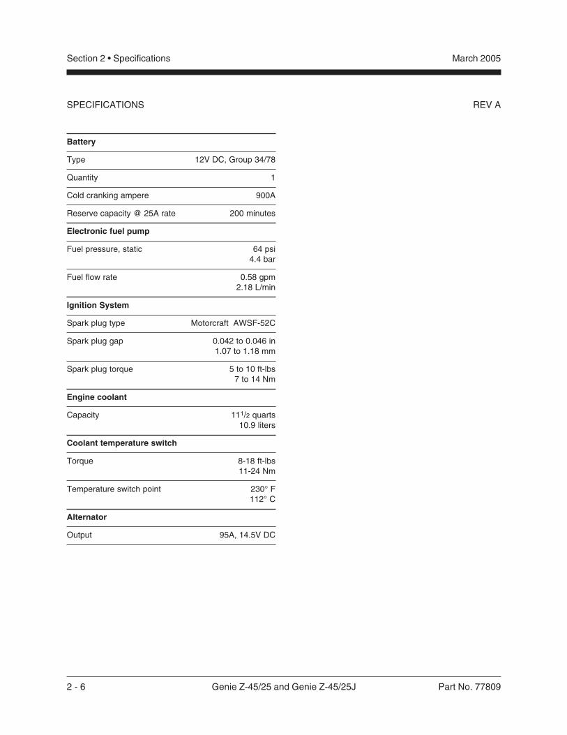
Battery
Type 12V DC, Group 34/78
Quantity 1
Cold cranking ampere 900A
Reserve capacity @ 25A rate 200 minutes
Electronic fuel pump
Fuel pressure, static 64 psi4.4 bar
Fuel flow rate 0.58 gpm2.18 L/min
Ignition System
Spark plug type Motorcraft AWSF-52C
Spark plug gap 0.042 to 0.046 in1.07 to 1.18 mm
Spark plug torque 5 to 10 ft-lbs7 to 14 Nm
Engine coolant
Capacity 111/2 quarts10.9 liters
Coolant temperature switch
Torque 8-18 ft-lbs11-24 Nm
Temperature switch point 230° F112° C
Alternator
Output 95A, 14.5V DC

Part No. 77809 Genie Z-45/25 and Genie Z-45/25J 2 - 7
Section 2 • SpecificationsMarch 2005
REV A SPECIFICATIONS
Oil temperature switch specifications
Torque 8-18 ft-lbs11-24 Nm
Temperature switch point 220° F104° C
Oil pressure switch specifications
Torque 8-18 ft-lbs11-24 Nm
Oil pressure switch point 15 psi1 bar
Fuel injection system
Injection pump make OMAP
Injection pump pressure 4351 psi300 bar
Injector opening pressure 3626 psi250 bar
Fuel requirement diesel number 2-D
Alternator output 60A, 14V DC
Starter motor
Current draw, no load 90A
Brush length, new 0.72 in18.5 mm
Brush length, minimum 0.27 in7 mm
Battery
Type 12V DC, Group 34/78
Quantity 1
Cold cranking ampere 900A
Reserve capacity @ 25A rate 200 minutes
Fan belt deflection 3/8 to 1/2 inch9 to 12 mm
Deutz F3L 1011F Engine
Displacement 125 cu in2.05 liters
Number of cylinders 3
Bore and stroke 3.58 x 4.13 inches91 x 105 mm
Horsepower
Gross intermittent @ 3000 rpm 44Continuous @ 3000 rpm 40Horsepower @ 2500 rpm 36
Firing order 1 - 2 - 3
Low idle 1400 rpm
High idle 2500 rpm
Compression ratio 18.5:1
Compression pressure 362 to 435 psi25 to 30 bar
Governor centrifugal mechanical
Valve clearance, cold
Intake 0.012 in0.3 mm
Exhaust 0.020 in0.5 mm
Lubrication system
Oil pressure 26 to 87 psi1.8 to 6 bar
Oil capacity 6.5 quarts(including filter) 6 liters
Oil viscosity requirements
Below 60°F / 15.5°C 5W-30(synthetic)
-10°F to 90°F / -23°C to 32°C 10W-40
Above -4°F / -34°C 15W-40
Engine oil should have minimum properties of APIclassification CC/SG or CD/SG grades.Units ship with 10W-40 CH-4

2 - 8 Genie Z-45/25 and Genie Z-45/25J Part No. 77809
Section 2 • Specifications March 2005
REV A
Perkins 104-22 Engine(KR model)
Displacement 135 cu in2.2 liters
Number of cylinders 4
Bore and stroke 3.31 x 3.94 inches84 x 100 mm
Horsepower
Gross intermittent @ 2800 rpm 50Net intermittent @ 2800 rpm 46.9Net continuous @ 2800 rpm 41Intermittent @ 2500 rpm 44
Firing order 1 - 3 - 4 - 2
Low idle 1600 rpm
High idle 2500 rpm
Compression ratio 22:1
Compression pressure 300 to 500 psi20.7 to 34.5 bar
Pressure (psi) of lowest cylinder mustbe within 50 psi / 3.45 bar of highest cylinder
Governor centrifugal mechanical
Valve clearance, cold
Intake 0.008 in0.2 mm
Exhaust 0.008 in0.2 mm
Lubrication system
Oil pressure @ 2500 rpm 41 psi2.8 bar
Oil capacity 8.6 quarts(including filter) 8.2 liters
Oil viscosity requirements
Below 68°F / 20°C (synthetic) 5W-20
5°F to 104°F / -15°C to 40°C 10W-30
Above 14°F / -10°C 15W-40
Engine oil should have minimum properties of APIclassification CC/SE. API classification CD/SE or CCMCD4 can be used, but is not recommended during thefirst 50 hours nor for light load applications.Units ship with CH-4
Oil pressure sending unit
Torque 8-18 ft-lbs11-24 Nm
Oil pressure switch point 4.2 psi0.3 bar
Fuel injection system
Injection pump make Zexel
Injection pressure 2133 psi147 bar
Fuel requirement #2 Diesel
Alternator output 55A @ 13.8V DC
Starter motor
Current draw, no load 90A
Brush length, new 0.7480 in19 mm
Brush length, minimum 0.5 in12.7 mm
SPECIFICATIONS

Part No. 77809 Genie Z-45/25 and Genie Z-45/25J 2 - 9
Section 2 • SpecificationsMarch 2005
REV A
Perkins Engine 104-22(KR model), continued
Battery
Type 12V DC, Group 34/78
Quantity 1
Cold cranking ampere 900A
Reserve capacity @ 25A rate 200 minutes
Fan belt deflection 3/8 in10 mm
Engine coolant
Capacity 7.7 quarts7.3 liters
Coolant temperature sending unit
Torque 8-18 ft-lbs11-24 Nm
Temperature switch point 221° F 105° C
SPECIFICATIONS

2 - 10 Genie Z-45/25 and Genie Z-45/25J Part No. 77809
Section 2 • Specifications March 2005
REV A
Machine Torque Specifications
Platform rotator
1-8 center bolt 480 ft-lbs651 Nm
3/8 -16 bolts 47 ft-lbs63.7 Nm
Drive motor and hubs
Drive hub mounting bolts, dry 200 ft-lbs271 Nm
Drive hub mounting bolts, lubricated 150 ft-lbs203 Nm
Drive motor mounting bolts, dry 75 ft-lbs102 Nm
Drive motor mounting bolts, lubricated 56 ft-lbs76 Nm
SPECIFICATIONS

Part No. 77809 Z-45/25 • Z-45/25J 2 - 11
Section 2 • SpecificationsAugust 2005
REV B SPECIFICATIONS
Hydraulic Hose and FittingTorque SpecificationsYour machine is equipped with Parker Seal-Lok®
fittings and hose ends. Genie specifications requirethat fittings and hose ends be torqued tospecification when they are removed and installedor when new hoses or fittings are installed.
SAE O-ring Boss Port(tube fitting - installed into Aluminum)
SAE Dash size Torque
-4 11 ft-lbs / 14.9 Nm
-6 23 ft-lbs / 31.2 Nm
-8 40 ft-lbs / 54.2 Nm
-10 69 ft-lbs / 93.6 Nm
-12 93 ft-lbs / 126.1 Nm
-16 139 ft-lbs / 188.5 Nm
-20 172 ft-lbs / 233.2 Nm
-24 208 ft-lbs / 282 Nm
SAE O-ring Boss Port(tube fitting - installed into Steel)
SAE Dash size Torque
-4 16 ft-lbs / 21.7 Nm
-6 35 ft-lbs / 47.5 Nm
-8 60 ft-lbs / 81.3 Nm
-10 105 ft-lbs / 142.4 Nm
-12 140 ft-lbs / 190 Nm
-16 210 ft-lbs / 284.7 Nm
-20 260 ft-lbs / 352.5 Nm
-24 315 ft-lbs / 427.1 Nm
Seal-Lok® Fittings(hose end)
SAE Dash size Torque
-4 18 ft-lbs / 25 Nm
-6 30 ft-lbs / 40 Nm
-8 40 ft-lbs / 55 Nm
-10 60 ft-lbs / 80 Nm
-12 85 ft-lbs / 115 Nm
-16 110 ft-lbs / 150 Nm
-20 140 ft-lbs / 190 Nm
-24 180 ft-lbs / 245 Nm
Seal-Lok® fittings
1 Replace the O-ring. The O-ring must bereplaced anytime the seal has been broken.The O-ring cannot be re-used if the fitting orhose end has been tightened beyond fingertight.
The O-rings used in the ParkerSeal Lok® fittings and hose endsare custom-size O-rings. They arenot standard SAE size O-rings.They are available in the O-ringfield service kit (Genie partnumber 49612).
2 Lubricate the O-ring before installation.
3 Be sure that the face seal O-ring is seated andretained properly.
4 Position the tube and nut squarely on the faceseal end of the fitting and tighten the nut fingertight.
5 Tighten the nut or fitting to the appropriatetorque per given size as shown in the table.
6 Operate all machine functions and inspect thehoses and fittings and related components toconfirm that there are no leaks.

2 - 12 Z-45/25 • Z-45/25J Part No. 77809
Section 2 • Specifications June 2005
REV A
SIZE THREAD
in-lbs N m in-lbs N m in-lbs N m in-lbs N m in-lbs N m20 100 11.3 80 9 140 15.8 110 12.4 130 14.728 90 10.1 120 13.5 120 13.5 160 18 140 15.8
f t -lbs N m f t -lbs N m f t -lbs N m f t -lbs N m f t -lbs N m18 13 17.6 17 23 18 24 25 33.9 21 28.424 14 19 19 25.7 20 27.1 27 36.6 24 32.516 23 31.2 31 42 33 44.7 44 59.6 38 51.524 26 35.2 35 47.4 37 50.1 49 66.4 43 58.314 37 50.1 49 66.4 50 67.8 70 94.7 61 82.720 41 55.5 55 74.5 60 81.3 80 108.4 68 92.113 57 77.3 75 101.6 80 108.4 110 149 93 12620 64 86.7 85 115 90 122 120 162 105 14212 80 108.4 110 149 120 162 150 203 130 17618 90 122 120 162 130 176 170 230 140 18911 110 149 150 203 160 217 210 284 180 24418 130 176 170 230 180 244 240 325 200 27110 200 271 270 366 280 379 380 515 320 43316 220 298 300 406 310 420 420 569 350 4749 320 433 430 583 450 610 610 827 510 69114 350 474 470 637 500 678 670 908 560 7598 480 650 640 867 680 922 910 1233 770 104412 530 718 710 962 750 1016 990 1342 840 11397 590 800 790 1071 970 1315 1290 1749 1090 147712 670 908 890 1206 1080 1464 1440 1952 1220 16547 840 1138 1120 1518 1360 1844 1820 2467 1530 207412 930 1260 1240 1681 1510 2047 2010 2725 1700 23046 1460 1979 1950 2643 2370 3213 3160 4284 2670 362012 1640 2223 2190 2969 2670 3620 3560 4826 3000 4067
LUBEDDRYLUBED
SAE FASTENER TORQUE CHART
Grade 5
DRYLUBED
• This chart is to be used as a guide only unless noted elsewhere in this manual •A574 High Strength Black Oxide Bolts
Grade 8
LUBED
1/4
LUBED DRY LUBED DRY
1 1/2
9/16
5/8
3/4
7/8
1
1 1/8
1 1/4
5/16
3/8
7/16
1/2
Size
(mm)in-lbs N m in-lbs N m in-lbs N m in-lbs N m in-lbs N m in-lbs N m in-lbs N m in-lbs N m
5 16 1.8 21 2.4 41 4.63 54 6.18 58 6.63 78 8.84 68 7.75 91 10.36 19 3.05 36 4.07 69 7.87 93 10.5 100 11.3 132 15 116 13.2 155 17.67 45 5.12 60 6.83 116 13.2 155 17.6 167 18.9 223 25.2 1.95 22.1 260 29.4
f t -lbs N m f t -lbs N m f t -lbs N m f t -lbs N m f t -lbs N m f t -lbs N m f t -lbs N m f t -lbs N m8 5.4 7.41 7.2 9.88 14 19.1 18.8 25.5 20.1 27.3 26.9 36.5 23.6 32 31.4 42.6
10 10.8 14.7 14.4 19.6 27.9 37.8 37.2 50.5 39.9 54.1 53.2 72.2 46.7 63.3 62.3 84.412 18.9 25.6 25.1 34.1 48.6 66 64.9 88 69.7 94.5 92.2 125 81 110 108 14714 30.1 40.8 40 54.3 77.4 105 103 140 110 150 147 200 129 175 172 23416 46.9 63.6 62.5 84.8 125 170 166 226 173 235 230 313 202 274 269 36518 64.5 87.5 86.2 117 171 233 229 311 238 323 317 430 278 377 371 50320 91 124 121 165 243 330 325 441 337 458 450 610 394 535 525 71322 124 169 166 225 331 450 442 600 458 622 612 830 536 727 715 97024 157 214 210 285 420 570 562 762 583 791 778 1055 682 925 909 1233
LUBED DRY LUBED DRYLUBED DRY LUBED DRY
LUBEDDRYLUBED
Class 12.9Class 4.6
DRYLUBED
METRIC FASTENER TORQUE CHART• This chart is to be used as a guide only unless noted elsewhere in this manual •
LUBED DRY
Class 10.9Class 8.8
DRY
10.9 12.98.84.6
SPECIFICATIONS

Part No. 77809 Genie Z-45/25 and Genie Z-45/25J 3 - 1
March 2005 Section 3 • Scheduled Maintenance Procedures
Scheduled Maintenance Procedures
Observe and Obey:
Maintenance inspections shall be completed bya person trained and qualified on themaintenance of this machine.
Scheduled maintenance inspections shall becompleted daily, quarterly, six months, annuallyand every 2 years as specified on theMaintenance Inspection Report.
Failure to perform each procedureas presented and scheduled maycause death, serious injury orsubstantial damage.
Immediately tag and remove from service adamaged or malfunctioning machine.
Repair any machine damage or malfunctionbefore operating machine.
Keep records on all inspections for three years.
Unless otherwise specified, perform eachmaintenance procedure with the machine in thefollowing configuration:
· Machine parked on a firm, level surface
· Boom in stowed position
· Turntable rotated with the boom betweenthe non-steering wheels
· Turntable secured with the turntablerotation lock
· Key switch in the off position with thekey removed
· Wheels chocked
· All external AC power supply disconnectedfrom the machine
About This Section
This section contains detailed procedures for eachscheduled maintenance inspection.
Each procedure includes a description, safetyinformation and step-by-step instructions.
Symbols Legend
Safety alert symbol—used to alertpersonnel to potential personalinjury hazards. Obey all safetymessages that follow this symbolto avoid possible injury or death.
Used to indicate the presence ofan imminently hazardous situationwhich, if not avoided, will result indeath or serious injury.
Used to indicate the presence of apotentially hazardous situationwhich, if not avoided, could resultin death or serious injury.
With safety alert symbol—used toindicate the presence of apotentially hazardous situationwhich, if not avoided, may causeminor or moderate injury.
Without safety alert symbol—usedto indicate the presence of apotentially hazardous situationwhich, if not avoided, may result inproperty damage.
Used to indicate operation ormaintenance information.
Indicates that a specific result is expected afterperforming a series of steps.
Indicates that an incorrect result has occurredafter performing a series of steps.

3 - 2 Genie Z-45/25 and Genie Z-45/25J Part No. 77809
March 2005Section 3 • Scheduled Maintenance Procedures
Maintenance Symbols Legend
The following symbols have beenused in this manual to helpcommunicate the intent of theinstructions. When one or more ofthe symbols appear at thebeginning of a maintenanceprocedure, it conveys the meaningbelow.
Indicates that tools will be required toperform this procedure.
Indicates that new parts will be requiredto perform this procedure.
Indicates that a cold engine will berequired to perform this procedure.
Indicates that a warm engine will berequired to perform this procedure.
Indicates that dealer service is requiredto perform this procedure.
Pre-delivery Preparation Report
The pre-delivery preparation report containschecklists for each type of scheduled inspection.
to use for each inspection. Store completed formsas required.
Maintenance Schedule
There are five types of maintenance inspectionsthat must be performed according to a schedule—daily, quarterly, six months, annual, and two years.The Scheduled Maintenance Procedures Sectionand the Maintenance Inspection Report have beendivided into five subsections—A, B, C, D and E.Use the following chart to determine which group(s)of procedures are required to perform a scheduledinspection.
Inspection Table or Checklist
Daily or every 8 hours A
Quarterly or every 250 hours A + B
Six months or every 500 hours A + B + C
Annual or every 1000 hours A + B + C + D
Two years or every 2000 hours A + B + C + D + E
Maintenance Inspection Report
The maintenance inspection report containschecklists for each type of scheduled inspection.
Make copies of the Maintenance Inspection Reportto use for each inspection. Store completed formsfor three years.
SCHEDULED MAINTENANCE PROCEDURES
Genie Industries USA18340 NE 76th StreetPO Box 97030Redmond, WA 98073-9730(425) 881-1800
Copyright © 2002 by Genie Industries. Genie® is a registered trademark of Genie Industries.Rev A
Genie UKThe Maltings, Wharf Road
Grantham, LincolnshireNG31- 6BH England
(44) 1476-584333
Pre-Delivery Preparation Y N R
Pre-operation inspection completed
Maintenance items completed
Function tests completed
Model
Serial number
Date
Machine owner
Inspected by (print)
Inspector signature
Inspector title
Inspector company
Instructions
Use the operator’s manual on your machine.
The Pre-delivery Preparation consists of completing thePre-operation Inspection, the Maintenance items and theFunction Tests.
Use this form to record the results. Place a check in theappropriate box after each part is completed. Follow theinstructions in the operator’s manual.
If any inspection receives an N, remove the machine fromservice, repair and re-inspect it. After repair, place a checkin the R box.
LegendY = yes, completedN = no, unable to completeR = repaired
Comments
Fundamentals
It is the responsibility of the dealer to perform thePre-delivery Preparation.
The Pre-delivery Preparation is performed prior to eachdelivery. The inspection is designed to discover if anythingis apparently wrong with a machine before it is put intoservice.
A damaged or modified machine must never be used. Ifdamage or any variation from factory delivered condition isdiscovered, the machine must be tagged and removed fromservice.
Repairs to the machine may only be made by a qualifiedservice technician, according to the manufacturer'sspecifications.
Scheduled maintenance inspections shall be performed byqualified service technicians, according to themanufacturer's specifications and the requirements listed inthe responsibilities manual.

3 - 4 Genie Z-45/25 and Genie Z-45/25J Part No. 77809
March 2005Section 3 • Scheduled Maintenance Procedures
This page intentionally left blank.

Part No. 77809 Z-45/25 • Z-45/25J 3 - 5
August 2005 Section 3 • Scheduled Maintenance Procedures
Checklist A - Rev E Y N R
A-1 Pre-operationinspection
A-2 Functions tests
A-3 Engine maintenance -Deutz models
A-4 Engine maintenance -Ford models
A-5 Engine maintenance -Perkins models
A-6 Filter condition indicator
A-7 Oscillate axle
Perform after 40 hours:
A-8 30 day service
Perform every 100 hours:
A-9 Engine maintenance -Ford and Perkinsmodels
A-10 Fuel filters -Ford models
A-11 Fuel filter/separator -Diesel models
A-12 Check engine RPM-Perkins models
A-13 Rotation bearing
Perform every 200 hours:
A-14 Engine maintenance -Ford models
A-15 Engine maintenance -Perkins models
Instructions· Make copies of both pages to use
for each inspection.
· Select the appropriate checklist(s)for the type of inspection to beperformed.
Daily or 8 hourInspection: A
Quarterly or 250 hourInspection: A+B
Six Month or 500 hourInspection: A+B+C
Annual or 1000 hoursInspection: A+B+C+D
2 Year or 2000 hourInspection: A+B+C+D+E
· Place a check in the appropriate boxafter each inspection procedure iscompleted.
· If any inspection receives an “N”, tagand remove the machine fromservice, repair and re-inspect it. Afterrepair, place a check in the “R” box.
LegendY = yes, acceptableN = no, remove from service
R = repaired
Comments
Model
Serial number
Date
Hour meter
Machine owner
Inspected by (print)
Inspector signature
Inspector title
Inspector company
Checklist B - Rev D Y N R
B-1 Battery
B-2 Electrical wiring
B-3 Key switch
B-4 Engine maintenance -Ford models
B-5 Exhaust system
B-6 Oil cooler and fins-Deutz models
B-7 Lug nut torque
B-8 Brake configuration
B-9 Drive hub oil level
B-10 Engine RPM - Fordand Deutz models
B-11 Ground control override
B-12 Directional valve
B-13 Platform leveling
B-14 Engine idle select
B-15 Fuel select -Ford models
B-16 Drive brakes
B-17 Drive speed -stowed position
B-18 Drive speed -raised position
B-19 Alarm package
B-20 Hydraulic oil analysis
B-21 Fuel filter/separator -Perkins models
B-22 Replace fuel filter -Perkins models
Perform every 400 hours:
B-23 Engine maintenance -Deutz models
B-24 Engine maintenance -Ford models
B-25 Engine maintenance -Perkins models
Maintenance Inspection Report

3 - 6 Z-45/25 • Z-45/25J Part No. 77809
August 2005Section 3 • Scheduled Maintenance Procedures
Checklist C - Rev C Y N R
C-1 Engine maintenance -Deutz models
C-2 Grease platformoverload (if equipped)
C-3 Test platform overload(if equipped)
Perform every 600 hours:
C-4 Engine maintenance -Perkins models
Perform every 800 hours:
C-5 Engine maintenance -Ford models
Checklist D - Rev D Y N R
D-1 Boom wear pads
D-2 Turntable bearing bolts
D-3 Free-wheelconfiguration
D-4 Drive hub oil
D-5 Air/LPG mixture -Ford models
D-6 Engine maintenance -Deutz models
D-7 Turntable bearing wear
D-8 Calibrate platformoverload system(if equipped)
D-9 Hydraulic filters
MAINTENANCE INSPECTION REPORT
Checklist E - Rev B Y N R
E-1 Hydraulic oil
E-2 Fuel hoses -Ford models
E-3 Engine maintenance -Deutz models
E-4 Grease steer axlewheel bearings,2WD models
Instructions· Make copies of both pages to use
for each inspection.
· Select the appropriate checklist(s)for the type of inspection to beperformed.
Daily or 8 hourInspection: A
Quarterly or 250 hourInspection: A+B
Six Month or 500 hourInspection: A+B+C
Annual or 1000 hoursInspection: A+B+C+D
2 Year or 2000 hourInspection: A+B+C+D+E
· Place a check in the appropriate boxafter each inspection procedure iscompleted.
· If any inspection receives an “N”, tagand remove the machine fromservice, repair and re-inspect it. Afterrepair, place a check in the “R” box.
LegendY = yes, acceptableN = no, remove from service
R = repaired
Comments
Model
Serial number
Date
Hour meter
Machine owner
Inspected by (print)
Inspector signature
Inspector title
Inspector company

Part No. 77809 Z-45/25 • Z-45/25J 3 - 7
August 2005 Section 3 • Scheduled Maintenance Procedures
REV E
A-1Perform Pre-operationInspectionCompleting a pre-operation inspection is essentialto safe machine operation. The pre-operationinspection is a visual inspection performed by theoperator prior to each work shift. The inspection isdesigned to discover if anything is apparently wrongwith a machine before the operator performs thefunction tests. The pre-operation inspection alsoserves to determine if routine maintenanceprocedures are required.
Complete information to perform this procedure isavailable in the Genie Z-45/25 and Genie Z-45/25JOperator's Manual on your machine.
Checklist A Procedures
A-2Perform Function TestsCompleting the function tests is essential to safemachine operation. Function tests are designed todiscover any malfunctions before the machine isput into service. A malfunctioning machine mustnever be used. If malfunctions are discovered, themachine must be tagged and removed fromservice.
Complete information to perform this procedure isavailable in the Genie Z-45/25 and Genie Z-45/25JOperator's Manual on your machine.

3 - 8 Z-45/25 • Z-45/25J Part No. 77809
August 2005Section 3 • Scheduled Maintenance Procedures
REV ECHECKLIST A PROCEDURES
A-3Perform Engine Maintenance -Deutz Models
Engine specifications require thatthis procedure be performed dailyor every 10 hours, whichevercomes first.
Proper engine maintenance, following the enginemanufacturer's maintenance schedule, is essentialto good engine performance and service life. Failureto perform the maintenance procedures can lead topoor engine performance and component damage.
Required maintenance procedures and additionalengine information are available in theDeutz FL 1011F Operation Manual(Deutz part number 0297 9683).
Deutz FL 1011F Operation ManualGenie part number 52883
To access the engine:
1 Remove the safety pin from the engine pivotplate latch.
The engine pivot plate latch islocated under the engine turntablepivot plate at the counterweightend of the machine.
2 Open the engine pivot plate latch and swing theengine pivot plate out and away from themachine.
A-4Perform Engine Maintenance -Ford Models
Engine specifications require thatthis procedure be performed dailyor every 8 hours, whichever comesfirst.
Proper engine maintenance, following the enginemanufacturer's maintenance schedule, is essentialto good engine performance and service life. Failureto perform the maintenance procedures can lead topoor engine performance and component damage.
Required maintenance procedures and additionalengine information are available in theFord LRG-425 EFI Operator Handbook(Ford part number FPP 194-302).
Ford LRG-425 EFI Operator HandbookGenie part number 84792
To access the engine:
1 Remove the safety pin from the engine pivotplate latch.
The engine pivot plate latch islocated under the engine turntablepivot plate at the counterweightend of the machine.
2 Open the engine pivot plate latch and swing theengine pivot plate out and away from themachine.

Part No. 77809 Z-45/25 • Z-45/25J 3 - 9
August 2005 Section 3 • Scheduled Maintenance Procedures
REV E CHECKLIST A PROCEDURES
A-5Perform Engine Maintenance -Perkins Models
Engine specifications require thatthis procedure be performed dailyor every 8 hours, whichever comesfirst.
Proper engine maintenance, following the enginemanufacturer's maintenance schedule, is essentialto good engine performance and service life. Failureto perform the maintenance procedures can lead topoor engine performance and component damage.
Required maintenance procedures and additionalengine information are available in thePerkins 100 Series Workshop Manual(Perkins part number TPD 1377E).
Perkins 100 Series Workshop ManualGenie part number 72352
To access the engine:
1 Remove the safety pin from the engine pivotplate latch.
The engine pivot plate latch islocated under the engine turntablepivot plate at the counterweightend of the machine.
2 Open the engine pivot plate latch and swing theengine pivot plate out and away from themachine.
A-6Check the High PressureHydraulic Filter ConditionIndicatorMaintaining the high pressure hydraulic filter ingood condition is essential to good systemperformance and safe machine operation. The filtercondition indicator will show when the hydraulic flowis bypassing a clogged filter. If the filter is notfrequently checked and replaced, impurities willremain in the hydraulic system and causecomponent damage.
1 Open the engine side turntable cover.
2 Start the engine from the ground controls.
3 Change the engine idle to high rpm (rabbitsymbol).
4 Visually inspect the filter condition indicator.
Result: The filter condition indicator should beoperating with the plunger in the green area.
Result: If the indicator displays the plunger inthe red area, this indicates that the hydraulicfilter is being bypassed and the filter should bereplaced. See D-9, Replace the HydraulicFilters.

3 - 10 Z-45/25 • Z-45/25J Part No. 77809
August 2005Section 3 • Scheduled Maintenance Procedures
REV E
A-7Test the Oscillate Axle(if equipped)
Proper axle oscillation is essential to safe machineoperation. If the axle oscillation system is notoperating correctly, the stability of the machine iscompromised and it may tip over.
1 Start the engine from the platform controls.
2 Drive the right steer tire up onto a 6 inch /15.2 cm block or curb.
Result: The three remaining tires should stay infirm contact with the ground and the chassisshould remain level at all times.
3 Drive the left steer tire up onto a 6 inch /15.2 cm block or curb.
Result: The three remaining tires should stay infirm contact with the ground and the chassisshould remain level at all times.
4 Drive both steer tires up onto a 6 inch /15.2 cm block or curb.
Result: The non-steer tires should stay in firmcontact with the ground.
If the chassis does not remainlevel during test, refer to RepairProcedure 8-8, How to Set Up theDirectional Valve Linkage.
A-8Perform 30 Day Service
The 30 day maintenance procedure is a one timesequence of procedures to be performed after thefirst 30 days or 40 hours of usage, whichevercomes first. After this interval, refer to themaintenance checklist for continued scheduledmaintenance.
1 Perform the following maintenance procedures:
• A-9 Perform Engine Maintenance -Ford and Perkins Models
• A-13 Grease the Turntable Rotation Bearingand Rotate Gear
• B-7 Check the Lug Nut Torque(including tires and wheels)
• B-9 Check the Oil Level in the Drive Hubs
• C-1 Perform Engine Maintenance -Deutz Models
• D-2 Check the Turnable Rotation BearingBolts
• D-9 Replace the Hydraulic Filters
CHECKLIST A PROCEDURES

Part No. 77809 Z-45/25 • Z-45/25J 3 - 11
August 2005 Section 3 • Scheduled Maintenance Procedures
REV E
A-9Perform Engine Maintenance -Ford and Perkins Models
Engine specifications require thatthis procedure be performed every100 hours. Perform this proceduremore often if dusty conditions existor the machine is subjected toextended low idle operation.
Proper engine maintenance, following the enginemanufacturer's maintenance schedule, is essentialto good engine performance and service life. Failureto perform the maintenance procedures can lead topoor engine performance and component damage.
Required maintenance procedures and additionalengine information are available in theFord LRG-425 EFI Operator Handbook(Ford part number FPP 194-302) OR thePerkins 100 Series Workshop Manual(Perkins part number TPD 1377E).
Ford LRG-425 EFI Operator HandbookGenie part number 84792
Perkins 100 Series Workshop ManualGenie part number 72352
To access the engine:
1 Remove the safety pin from the engine pivotplate latch.
The engine pivot plate latch islocated under the engine turntablepivot plate at the counterweightend of the machine.
2 Open the engine pivot plate latch and swing theengine pivot plate out and away from themachine.
A-10Replace the FuelFilters - Ford Models
Engine specifications require thatthis procedure be performed every100 hours.
Replacing the gasoline fuel filters is essential togood engine performance and service life. A dirty orclogged filter may cause the engine to performpoorly and continued use may cause componentdamage. Extremely dirty conditions may requirethat the filter be replaced more often.
Explosion and fire hazard. Enginefuels are combustible. Replace thefuel filter in an open, well-ventilatedarea away from heaters, sparks,flames and lighted tobacco.Always have an approved fireextinguisher within easy reach.
Perform this procedure with theengine off.
1 Put on protective clothing and eye wear.
2 Open the tank side turntable cover and locatethe fuel system components mounted to theplate under the fuel tank.
CHECKLIST A PROCEDURES

3 - 12 Z-45/25 • Z-45/25J Part No. 77809
August 2005Section 3 • Scheduled Maintenance Procedures
REV ECHECKLIST A PROCEDURES
3 Remove the fuel system plate retainingfasteners. Carefully lower the fuel system plate.
4 At the pre-filter, disconnect and plug the fuelhose that goes to the fuel tank.
5 Disconnect the fuel hose from the fuel pre-filterto the fuel pump. Remove the pre-filter.
6 Install the new fuel pre-filter and connect the fuelhose between the fuel pump and the pre-filter.
Be sure the arrow on the pre-filteris pointing towards the fuel pump.
7 Tag and disconnect the fuel hoses from thepressure regulator/filter.
Explosion and fire hazard.Electronic Fuel Injection (EFI)systems operate at a very highpressure. Fuel may be expelledunder pressure if the hoses areremoved too quickly. Loosen thefuel lines very slowly to allow thefuel pressure to dissipategradually. Wrap a cloth around fuelhoses to absorb leaking fuel beforedisconnecting them.
8 Remove the regulator/filter mounting fastenersand remove the regulator/filter from the fuelsystem mounting plate.
9 Install the new regulator/filter onto the fuelsystem mounting plate. Connect the fuel hosesto the regulator/filter.
Component damage hazard. Besure the correct regulator/filter isinstalled or component damagemay occur.
Be sure each fuel hose isconnected to the correct port of thepressure/regulator.
10 Install the fuel hose from the fuel tank to the fuelpre-filter.
11 Clean up any fuel that may have spilled duringthe installation procedure.
12 Start the machine from the ground controls.Inspect the fuel filters and hoses for leaks.
Explosion and fire hazard. If a fuelleak is discovered, keep anyadditional personnel from enteringthe area and do not operate themachine. Repair the leakimmediately.
Fuel Pump
Fuel pressureregulator/filter
Pre-Filter
“To engine”
“From tank”
“Return to tank”

Part No. 77809 Z-45/25 • Z-45/25J 3 - 13
August 2005 Section 3 • Scheduled Maintenance Procedures
REV E CHECKLIST A PROCEDURES
A-11Inspect the Fuel Filter/ WaterSeparator - Diesel Models
Engine specifications require thatthis procedure be performed every100 hours.
Proper maintenance of the fuel filter/water separatoris essential for good engine performance. Failure toperform this procedure can lead to poor engineperformance and component damage.
Explosion and fire hazard. Enginefuels are combustible. Perform thisprocedure in an open, well-ventilated area away from heaters,sparks, flames and lightedtobacco. Always have an approvedfire extinguisher within easy reach.
Perform this procedure with theengine off.
Perkins models:
1 Put on protective clothing and eye wear.
2 Open the engine side turntable cover and locatethe fuel filter/water separator next to thehydraulic return filter on the bulkhead.
3 Visually inspect the filter bowl for water buildup.
Result: If water is present in the filter bowl,continue with steps 3 through 7.
4 Loosen the vent plug located on the fuel filter/water separator head.
a vent plugb drain plugc filter bowld separator head
5 Loosen the drain plug located at the bottom ofthe bowl. Allow the water to drain into a suitablecontainer until fuel starts to come out.Immediately tighten the drain plug.
6 Tighten the vent plug.
If the fuel filter/water separator iscompletely drained, you mustprime the fuel filter/water separatorbefore starting the engine.See B-22, Replace The Fuel FilterElement - Perkins Models, forinstructions on how to prime thefuel filter/water separator.
7 Clean up any fuel that may have spilled.
b
d
a
c

3 - 14 Z-45/25 • Z-45/25J Part No. 77809
August 2005Section 3 • Scheduled Maintenance Procedures
REV ECHECKLIST A PROCEDURES
8 Start the engine from the ground controls andcheck the fuel filter/water separator and ventplug for leaks.
Explosion and fire hazard. If a fuelleak is discovered, keep anyadditional personnel from enteringthe area and do not operate themachine. Repair the leakimmediately.
Deutz models:
1 Put on protective clothing and eye wear.
2 Remove the safety pin from the engine pivotplate latch.
The engine pivot plate latch islocated under the engine turntablepivot plate at the counterweightend of the machine.
3 Open the engine pivot plate latch and swing theengine pivot plate out and away from themachine.
4 Locate the fuel filter/water separator next to theoil filter.
5 Loosen the drain plug located at the bottom ofthe filter. Allow the water to drain into a suitablecontainer until fuel starts to come out.Immediately tighten the drain plug.
Do not completely drain the filter.
a fuel filter/water separatorb drain valve
6 Clean up any fuel that may have spilled.
7 Start the engine from the ground controls andcheck the fuel filter/water separator for leaks.
Explosion and fire hazard. If a fuelleak is discovered, keep anyadditional personnel from enteringthe area and do not operate themachine. Repair the leakimmediately.
8 Swing the engine back to its original positionand close the engine pivot plate latch.
9 Install the engine pivot plate safety pin.
a
b

Part No. 77809 Z-45/25 • Z-45/25J 3 - 15
August 2005 Section 3 • Scheduled Maintenance Procedures
REV E
A-12Check and Adjust theEngine RPM - Perkins Models
Engine specifications require thatthis procedure be performed every100 hours.
Maintaining the engine rpm at the proper setting forboth low and high idle is essential to good engineperformance and service life. The machine will notoperate properly if the rpm is incorrect andcontinued use may cause component damage.
This procedure will require twopeople.
1 Connect a tachometer to the engine. Start theengine from the ground controls.
Result: Low idle should be 1600 rpm.
Skip to step 3 if the low idle rpm is correct.
2 Loosen the low idle lock nut and turn the low idleadjustment screw clockwise to increase therpm, or counterclockwise to decrease the rpm.Tighten the low idle lock nut and confirm therpm.
a solenoid bootb high idle adjustment nutc yoked low idle lock nut and adjustment
screw
3 Move the function enable toggle switch to thehigh idle (rabbit symbol) position.
Result: High idle should be 2500 rpm.
If high idle rpm is correct, disregard adjustmentstep 4.
4 Loosen the yoke lock nut, then turn the high idleadjustment nut and solenoid bootcounterclockwise to increase the rpm orclockwise to decrease the rpm. Tighten theyoke lock nut and recheck the rpm.
Be sure the solenoid fully retractswhen activating high idle.
CHECKLIST A PROCEDURES
a b c d

3 - 16 Z-45/25 • Z-45/25J Part No. 77809
August 2005Section 3 • Scheduled Maintenance Procedures
REV E
A-13Grease the Turntable RotationBearing and Rotate Gear
Genie specifications require thatthis procedure be performed every100 hours of operation. Performthis procedure more often if dustyconditions exist.
Frequent application of lubrication to the turntablebearing and rotate gear is essential to goodmachine performance and service life. Continueduse of an improperly greased bearing and gear willresult in component damage.
1 Locate the grease fitting on the front turntablecover.
2 Pump grease into the turntable rotation bearing.Rotate the turntable in increments of 4 to 5inches / 10 to 13 cm at a time and repeat thisstep until the entire bearing has been greased.
3 Apply grease to each tooth of the drive gear,located under the turntable.
Grease Specification
Chevron Ultra-duty grease, EP NLGI 2 (lithium based)or equivalent
CHECKLIST A PROCEDURES
A-14Perform Engine Maintenance -Ford Models
Ford engine specifications requirethat this procedure be performedevery 200 hours.
Proper engine maintenance, following the enginemanufacturer's maintenance schedule, is essentialto good engine performance and service life. Failureto perform the maintenance procedures can lead topoor engine performance and component damage.
Required maintenance procedures and additionalengine information are available in theFord LRG-425 EFI Operator Handbook(Ford part number FPP 194-302).
Ford LRG-425 EFI Operator HandbookGenie part number 84792
To access the engine:
1 Remove the safety pin from the engine pivotplate latch.
The engine pivot plate latch islocated under the engine turntablepivot plate at the counterweightend of the machine.
2 Open the engine pivot plate latch and swing theengine pivot plate out and away from themachine.
Part No. 77809 Z-45/25 • Z-45/25J 3 - 17
August 2005 Section 3 • Scheduled Maintenance Procedures
REV E
A-15Perform Engine Maintenance -Perkins Models
Perkins engine specificationsrequire that this procedure beperformed every 200 hours.
Proper engine maintenance, following the enginemanufacturer's maintenance schedule, is essentialto good engine performance and service life. Failureto perform the maintenance procedures can lead topoor engine performance and component damage.
Required maintenance procedures and additionalengine information are available in thePerkins 100 Series Workshop Manual(Perkins part number TPD 1377E).
Perkins 100 Series Workshop ManualGenie part number 72352
To access the engine:
1 Remove the safety pin from the engine pivotplate latch.
The engine pivot plate latch islocated under the engine turntablepivot plate at the counterweightend of the machine.
2 Open the engine pivot plate latch and swing theengine pivot plate out and away from themachine.
CHECKLIST A PROCEDURES

3 - 18 Z-45/25 • Z-45/25J Part No. 77809
June 2005Section 3 • Scheduled Maintenance Procedures
REV D
B-1Inspect the Battery
Proper battery condition is essential to good engineperformance and operational safety. Improper fluidlevels or damaged cables and connections canresult in engine component damage and hazardousconditions.
Electrocution hazard. Contact withhot or live circuits could result indeath or serious injury. Remove allrings, watches and other jewelry.
Bodily injury hazard. Batteriescontain acid. Avoid spilling orcontacting battery acid. Neutralizebattery acid spills with baking sodaand water.
1 Put on protective clothing and eye wear.
2 Be sure that the battery cable connections arefree of corrosion.
3 Be sure that the battery hold downs and cableconnections are tight.
The battery is a maintenance freebattery and does not require thereplenishing of electrolyte.
Adding terminal protectors and acorrosion preventative sealant willhelp eliminate corrosion on thebattery terminals and cables.
Checklist B Procedures
B-2Inspect the Electrical Wiring
Maintaining electrical wiring in good condition isessential to safe operation and good machineperformance. Failure to find and replace burnt,chafed, corroded or pinched wires could result inunsafe operating conditions and may causecomponent damage.
Electrocution hazard. Contact withhot or live circuits could result indeath or serious injury. Remove allrings, watches and other jewelry.
1 Open the engine side turntable cover.
2 Remove the safety pin from the engine pivotplate latch.
The engine pivot plate latch islocated under the engine turntablepivot plate at the counterweightend of the machine.
3 Open the engine pivot plate latch and swing theengine pivot plate out and away from themachine.
4 Inspect the following areas for burnt, chafed,corroded and loose wires:
· Engine wiring harness
· Hydraulic manifold wiring
Part No. 77809 Z-45/25 • Z-45/25J 3 - 19
June 2005 Section 3 • Scheduled Maintenance Procedures
REV D
5 Open the ground controls side turntable cover.
6 Inspect the following areas for burnt, chafed,corroded and loose wires:
· Inside of the ground control box
· Hydraulic manifold wiring
7 Start the engine from the ground controls andraise the boom above the turntable covers.
8 Inspect the turntable area for burnt, chafed andpinched cables.
9 Lower the boom to the stowed position and turnthe engine off.
10 Inspect the following areas for burnt, chafed,corroded, pinched and loose wires:
· Cable track on the primary boom
· Cables on the primary, and jib booms
· Jib boom/Platform rotate manifold
· Inside of the platform control box
11 Swing the engine back to its original positionand close the engine pivot plate latch.
12 Install the engine pivot plate safety pin.
B-3Test the Key SwitchProper key switch action and response is essentialto safe machine operation. The machine can beoperated from the ground or platform controls andthe activation of one or the other is accomplishedwith the key switch. Failure of the key switch toactivate the appropriate control panel could cause ahazardous operating situation.
1 Pull out the red Emergency Stop button to theon position at both the ground and platformcontrols.
2 Turn the key switch to ground control, start theengine and then turn the key switch to platformcontrol.
3 Check all machine function from the groundcontrols.
Result: All machine functions should notoperate.
4 Turn the key switch to ground control.
5 Check all machine function from the platformcontrols.
Result: All machine functions should notoperate.
6 Turn the key switch to the off position.
Result: The engine should stop and no functionsshould operate.
CHECKLIST B PROCEDURES

3 - 20 Z-45/25 • Z-45/25J Part No. 77809
June 2005Section 3 • Scheduled Maintenance Procedures
REV D
B-4Perform Engine Maintenance -Ford Models
Ford engine specifications requirethat this procedure be performedevery 250 hours.
Proper engine maintenance, following the enginemanufacturer's maintenance schedule, is essentialto good engine performance and service life. Failureto perform the maintenance procedures can lead topoor engine performance and component damage.
Required maintenance procedures and additionalengine information are available in theFord LRG-425 EFI Operator Handbook(Ford part number FPP 194-302).
Ford LRG-425 EFI Operator HandbookGenie part number 84792
To access the engine:
1 Remove the safety pin from the engine pivotplate latch.
The engine pivot plate latch islocated under the engine turntablepivot plate at the counterweightend of the machine.
2 Open the engine pivot plate latch and swing theengine pivot plate out and away from themachine.
B-5Check the Exhaust SystemMaintaining the exhaust system is essential togood engine performance and service life. Runningthe engine with a damaged or leaking exhaustsystem can cause component damage and unsafeoperating conditions.
Bodily injury hazard. Do notinspect while the engine is running.Remove the key to secure fromoperation.
Burn hazard. Beware of hot enginecomponents. Contact with hotengine components may result insevere burns.
Ford models:
1 Remove the safety pin from the engine pivotplate latch.
The engine pivot plate latch islocated under the engine turntablepivot plate at the counterweightend of the machine.
2 Open the engine pivot plate latch and swing theengine pivot plate out and away from themachine to access the exhaust system.
All models:
3 Be sure that all nuts and bolts are tight.
4 Inspect all welds for cracks.
5 Inspect for exhaust leaks; i.e., carbon builduparound seams and joints.
Ford models:
6 Swing the engine back to its original positionand close the engine pivot plate latch.
7 Install the engine pivot plate safety pin.
CHECKLIST B PROCEDURES

Part No. 77809 Z-45/25 • Z-45/25J 3 - 21
June 2005 Section 3 • Scheduled Maintenance Procedures
REV D
B-6Check the Oil Cooler andCooling Fins - Deutz Models
Maintaining the oil cooler in good condition isessential for good engine performance. Operating amachine with a damaged oil cooler may result inengine damage. Also, restricting air flow throughthe oil cooler will affect the performance of thecooling system.
Bodily injury hazard. Do notinspect while the engineis running. Remove the key tosecure from operation.
Burn hazard. Beware of hot enginecomponents. Contact with hotengine components may result insevere burns.
Oil cooler
1 Remove the safety pin from the engine pivotplate latch.
The engine pivot plate latch islocated under the engine turntablepivot plate at the counterweightend of the machine.
2 Open the engine pivot plate latch and swing theengine pivot plate out and away from themachine.
3 Remove the fasteners from the engine sidecover, then remove the cover.
4 Inspect the oil cooler for leaks and physicaldamage.
a oil coolerb cylinder head cooling finsc fan blower fins
5 Clean the oil cooler of debris and foreignmaterial.
Cooling and fan blower fins
6 Inspect the fan blower fins for physical damage.
7 Clean the fan blower fins of debris and foreignmaterial.
8 Inspect the head cooling passages and fins forphysical damage or foreign material, using aflashlight.
9 Clean the cylinder head cooling passages ofdebris and foreign material.
10 Install the engine side cover.
11 Swing the engine back to its original positionand close the engine pivot plate latch.
12 Install the engine pivot plate safety pin.
CHECKLIST B PROCEDURES
cba
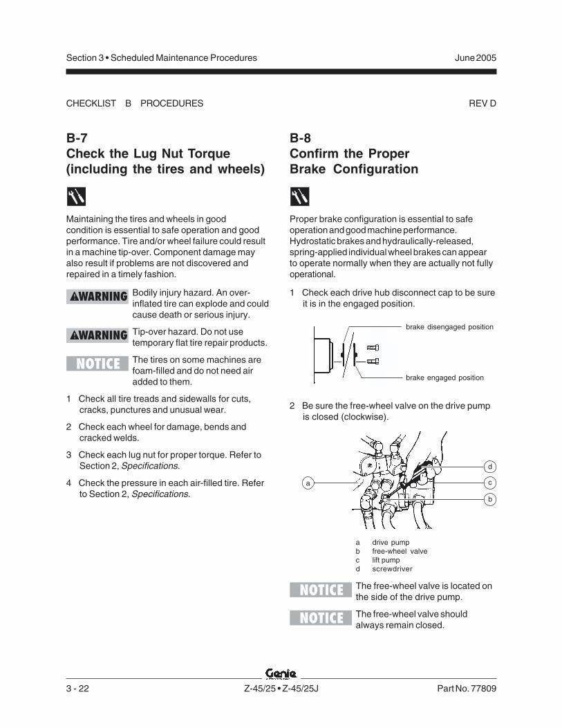
3 - 22 Z-45/25 • Z-45/25J Part No. 77809
June 2005Section 3 • Scheduled Maintenance Procedures
REV D
B-7Check the Lug Nut Torque(including the tires and wheels)
Maintaining the tires and wheels in goodcondition is essential to safe operation and goodperformance. Tire and/or wheel failure could resultin a machine tip-over. Component damage mayalso result if problems are not discovered andrepaired in a timely fashion.
Bodily injury hazard. An over-inflated tire can explode and couldcause death or serious injury.
Tip-over hazard. Do not usetemporary flat tire repair products.
The tires on some machines arefoam-filled and do not need airadded to them.
1 Check all tire treads and sidewalls for cuts,cracks, punctures and unusual wear.
2 Check each wheel for damage, bends andcracked welds.
3 Check each lug nut for proper torque. Refer toSection 2, Specifications.
4 Check the pressure in each air-filled tire. Referto Section 2, Specifications.
B-8Confirm the ProperBrake Configuration
Proper brake configuration is essential to safeoperation and good machine performance.Hydrostatic brakes and hydraulically-released,spring-applied individual wheel brakes can appearto operate normally when they are actually not fullyoperational.
1 Check each drive hub disconnect cap to be sureit is in the engaged position.
2 Be sure the free-wheel valve on the drive pumpis closed (clockwise).
a drive pumpb free-wheel valvec lift pumpd screwdriver
The free-wheel valve is located onthe side of the drive pump.
The free-wheel valve shouldalways remain closed.
CHECKLIST B PROCEDURES
a
b
c
d
brake disengaged position
brake engaged position

Part No. 77809 Z-45/25 • Z-45/25J 3 - 23
June 2005 Section 3 • Scheduled Maintenance Procedures
REV D
B-9Check the Oil Levelin the Drive Hubs
Failure to maintain proper drive hub oil levels maycause the machine to perform poorly and continueduse may cause component damage.
1 Drive the machine to rotate the hub until theplugs are located one on top and the other at90 degrees.
a drive hub plugs
2 Remove the plug located at 90 degrees andcheck the oil level.
Result: The oil level should be even with thebottom of the side plug hole.
3 If necessary, remove the top plug and add oiluntil the oil level is even with the bottom of theside plug hole.
4 Apply pipe thread sealant to the plug(s), andinstall the plug(s) in the drive hub.
5 Repeat this procedure for each drive hub.
B-10Check and Adjust theEngine RPM - Ford and DeutzModels
Maintaining the engine rpm at the proper setting forboth low and high idle is essential to good engineperformance and service life. The machine will notoperate properly if the rpm is incorrect andcontinued use may cause component damage.
Ford models:
The engine rpm is controlled by theECM and can only be adjusted byre-programming the ECM. If rpmadjustment or service is required,please contact Genie IndustriesService Department OR your localFord dealer.
Deutz models:
This procedure will require twopeople.
1 Remove the safety pin from the engine pivotplate latch.
The engine pivot plate latch islocated under the engine turntablepivot plate at the counterweightend of the machine.
2 Open the engine pivot plate latch and swing theengine pivot plate out and away from themachine.
CHECKLIST B PROCEDURES
a

3 - 24 Z-45/25 • Z-45/25J Part No. 77809
June 2005Section 3 • Scheduled Maintenance Procedures
REV D
3 Connect an rpm gauge to the engine, and thenstart the engine from the ground controls.
Result: Low idle should be 1400 rpm.
Skip to step 5 if the low idle rpm is correct.
4 Loosen the low idle lock nut, then turn the lowidle adjustment screw clockwise to increase therpm or counterclockwise to decrease the rpm.Tighten the low idle lock nut and recheck therpm.
a solenoid bootb high idle adjustment nutc yoke lock nutd yokee low idle adjustment screwf low idle lock nut
5 Move the function enable toggle switch to thehigh idle (rabbit symbol) position at the groundcontrols.
Result: High idle should be 2500 rpm.
If high idle rpm is correct, disregard adjustmentstep 6.
6 Loosen the yoke lock nut, then turn the high idleadjustment nut and solenoid bootcounterclockwise to increase the rpm orclockwise to decrease the rpm. Tighten theyoke lock nut and recheck the rpm.
Be sure the solenoid fully retractswhen activating high idle.
B-11Test the Ground ControlOverrideA properly functioning ground control override isessential to safe machine operation. The groundcontrol override function is intended to allow groundpersonnel to operate the machine from the groundcontrols whether or not the red Emergency Stopbutton on the platform controls is in the on or offposition. This function is particularly useful if theoperator at the platform controls cannot return theboom to the stowed position.
1 Push in the platform red Emergency Stop buttonto the off position.
2 Start the engine from the ground controls.
3 At the ground controls, operate each boomfunction through a partial cycle.
Result: All boom functions should operate.
CHECKLIST B PROCEDURES
f
e
c dba

Part No. 77809 Z-45/25 • Z-45/25J 3 - 25
June 2005 Section 3 • Scheduled Maintenance Procedures
REV D
B-12Check the Directional ValveLinkage
Perform this test only on modelsequipped with a oscillating axle.
Proper axle oscillation is essential to safe machineoperation. If the directional valve linkage is notoperating correctly, the stability of the machine iscompromised and it may tip over.
1 Remove the drive chassis cover and the axlecovers from the non-steer end of the drivechassis.
2 Locate the directional valve inside of the non-steer axle and inspect the linkage for thefollowing:
· Lock nut is tight against yoke
· Yoke clevis pins are installed
· Cotter pins are installed through clevis pins
· Linkage is properly attached todirectional valve
B-13Test the Platform Self-leveling
Automatic platform self-leveling throughoutthe full cycle of boom raising and lowering isessential for safe machine operation. Theplatform is maintained at level by the platformleveling slave cylinder which operates in a closedloop hydraulic circuit with the master cylinderlocated at the base of the boom.A platform self-leveling failure creates an unsafeworking condition for platform andground personnel.
1 Start the engine from the ground controls andlower the boom into the stowed position.
2 Hold the function enable toggle switch to eitherside and adjust the platform to a level positionusing the platform level toggle switch.
3 Raise and lower the primary boom througha full cycle.
Result: The platform should remain level atall times to within ±5 degrees.
CHECKLIST B PROCEDURES

3 - 26 Z-45/25 • Z-45/25J Part No. 77809
June 2005Section 3 • Scheduled Maintenance Procedures
REV D
B-14Test the Engine Idle SelectA properly operating engine idle select switchis essential to good engine performance and safemachine operation. There are two settings.
Foot switch activated low idle (turtle symbol)allows the operator to control individual boomfunctions. Drive functions will operate at low idle,but at reduced performance.
Foot switch activated high idle (rabbit symbol)should be used for normal machine operation. Thisselection activates high idle only when the footswitch is pressed down.
1 Pull out the red Emergency Stop button to theon position at both the ground and platformcontrols.
2 Start the engine from the ground controls thenmove the function enable toggle switch to thehigh idle (rabbit symbol) position and hold in theon position.
Result: The engine should change to high idle.
3 Release the function enable toggle switch.
Result: The engine should return to low idle.
4 Turn the key switch to platform controls.
5 Move the engine idle control switch to footswitch activated high idle (rabbit symbol).
Result: The engine should not change tohigh idle.
6 Press down the foot switch.
Result: The engine should change to high idle.
6 Move the engine idle control switch to footswitch activated low idle (turtle symbol).
Result: The engine should change to low idle.
B-15Test the Fuel Select Operation -Ford Models
The ability to select and switch betweengasoline and LPG fuels as needed is essential tosafe machine operation. A fuel selection can bemade when the engine is running or not.Switching malfunctions and/or the failure of theengine to start and run properly in both fuelmodes and through all idle speeds can indicate fuelsystem problems that could develop into ahazardous situation.
Perform this test after checkingthe gasoline and LPG fuel levels,and warming the engine to normaloperating temperature.
1 At the platform controls, move the fuel selectswitch to gasoline and then move the engineidle control switch to foot switch activated highidle (rabbit and foot switch symbol).
2 Start the engine from the platform controls andallow it to run at low idle.
3 Press down the foot switch to allow the engineto run at high idle.
Result: The engine should start promptly andoperate smoothly in low and high idle.
CHECKLIST B PROCEDURES

Part No. 77809 Z-45/25 • Z-45/25J 3 - 27
June 2005 Section 3 • Scheduled Maintenance Procedures
REV D
4 Release the foot switch and shut the engine offby pushing in the red Emergency Stop button into the off position.
5 Move the fuel select switch to LPG.
6 Restart the engine and allow it to run atlow idle.
7 Press down the foot switch to allow the engineto run at high idle.
Result: The engine should start promptly andoperate smoothly in low and high idle.
The engine may hesitatemomentarily and then continueto run on the selected fuel if thefuel source is switched whilethe engine is running.
B-16Test the Drive Brakes
Proper brake action is essential to safe machineoperation. The drive brake function should operatesmoothly, free of hesitation, jerking and unusualnoise. Hydrostatic brakes and hydraulically-released individual wheel brakes can appear tooperate normally when they are actually not fullyoperational.
Collision hazard. Be sure that themachine is not in free-wheel orpartial free-wheel configuration.Refer to B-8, Confirm the ProperBrake Configuration.
Select a test area that is firm, leveland free of obstructions.
1 Mark a test line on the ground for reference.
2 Start the engine from the platform controls.
3 Move the engine idle control switch tofoot switch activated high idle (rabbit andfoot switch), then lower the boom into thestowed position.
4 Choose a point on the machine; i.e., contactpatch of a tire, as a visual reference for usewhen crossing the test line.
5 Bring the machine to top drive speed beforereaching the test line. Release the drive joystickwhen your reference point on the machinecrosses the test line.
6 Measure the distance between the test line andyour machine reference point. Refer toSection 2, Specifications.
The brakes must be able to holdthe machine on any slope it is ableto climb.
CHECKLIST B PROCEDURES

3 - 28 Z-45/25 • Z-45/25J Part No. 77809
June 2005Section 3 • Scheduled Maintenance Procedures
REV D
B-17Test the Drive Speed -Stowed Position
Proper drive function movement is essential to safemachine operation. The drive function shouldrespond quickly and smoothly to operator control.Drive performance should also be free of hesitation,jerking and unusual noise over the entireproportionally controlled speed range.
Select a test area that is firm, leveland free of obstructions.
1 Create start and finish lines by marking two lineson the ground 40 feet / 12.2 m apart.
2 Start the engine from the platform controls.
3 Move the engine idle control switch tofoot switch activated high idle (rabbit and footswitch), then lower the boom into the stowedposition.
4 Choose a point on the machine; i.e., contactpatch of a tire, as a visual reference for usewhen crossing the start and finish lines.
5 Bring the machine to top drive speed beforereaching the start line. Begin timing when yourreference point on the machine crosses thestart line.
6 Continue at full speed and note the time whenthe machine reference point crosses the finishline. Refer to Section 2, Specifications.
B-18Test the Drive Speed -Raised or Extended Position
Proper drive function movement is essential to safemachine operation. The drive function shouldrespond quickly and smoothly to operator control.Drive performance should also be free of hesitation,jerking and unusual noise over the entireproportionally controlled speed range.
Select a test area that is firm, leveland free of obstructions.
1 Create start and finish lines by marking two lineson the ground 40 feet / 12.2 m apart.
2 Start the engine from the platform controls.
3 Move the engine idle select switch to foot switchactivated high idle (rabbit and foot switch).Press down the foot switch and raise the boomabove horizontal.
4 Choose a point on the machine; i.e., contactpatch of a tire, as a visual reference for usewhen crossing the start and finish lines.
5 Bring the machine to top drive speed beforereaching the start line. Begin timing when yourreference point on the machine crosses thestart line.
6 Continue at full speed and note the time whenthe machine reference point crosses the finishline.
CHECKLIST B PROCEDURES
Part No. 77809 Z-45/25 • Z-45/25J 3 - 29
June 2005 Section 3 • Scheduled Maintenance Procedures
REV D
7 Press down the foot switch and lower the boomto the stowed position.
8 Extend the boom 1 foot / 30 cm.
9 Choose a point on the machine; i.e., contactpatch of a tire, as a visual reference for usewhen crossing the start and finish lines.
10 Bring the machine to top drive speed beforereaching the start line. Begin timing when yourreference point on the machine crosses thestart line.
11 Continue at top speed and note the time whenthe machine reference point crosses the finishline. Refer to Section 2, Specifications.
B-19Test the Alarm Package(if equipped)The alarm package includes:
· Travel alarm
· Descent alarm
· Flashing beacon
Alarms and a beacon are installed to alert operatorsand ground personnel of machine proximity andmotion. The alarm package is installed on theturntable covers.
The alarms and beacon willoperate with the enginerunning or not running.
1 Turn the key switch to ground control and pullout the red Emergency Stop button to the onposition at both the ground and platformcontrols.
Result: The flashing beacon should be on andflashing.
2 Move the function enable switch to either sideand activate the primary boom toggle switch inthe down position, hold for a moment and thenrelease it.
Result: The descent alarm should sound whenthe switch is held down.
3 Move the function enable switch to either sideand activate the secondary boom toggle switchin the down position, hold for a moment andthen release it.
Result: The descent alarm should sound whenthe switch is held down.
CHECKLIST B PROCEDURES

3 - 30 Z-45/25 • Z-45/25J Part No. 77809
June 2005Section 3 • Scheduled Maintenance Procedures
REV D
4 Z-45/25J: Move the function enable switch toeither side and activate the jib boom toggleswitch in the down position, hold for a momentand then release it.
Result: The descent alarm should sound whenthe switch is held down.
5 Turn the key switch to platform control.
Result: The flashing beacon should be onand flashing.
6 Press down the foot switch. Move the primaryboom control handle to the down position, holdfor a moment and then release it.
Result: The descent alarm should sound whenthe control handle is held down.
7 Press down the foot switch. Move thesecondary boom control handle to the downposition, hold for a moment and then release it.
Result: The descent alarm should sound whenthe control handle is held down.
8 Z-45/25J: Press down the foot switch. Activatethe jib boom toggle switch in the down position,hold for a moment and then release it.
Result: The descent alarm should sound whenthe switch is held down.
9 Press down the foot switch. Move the drivecontrol handle off center, hold for a moment andthen release it. Move the drive control handle offcenter in the opposite direction, hold for amoment and then release it.
Result: The travel alarm should sound when thedrive control handle is moved off center in eitherdirection.
B-20Perform Hydraulic Oil Analysis
Replacement or testing of the hydraulic oil isessential for good machine performance andservice life. Dirty oil and a clogged suction straineror hydraulic filters may cause the machine toperform poorly and continued use may causecomponent damage. Extremely dirty conditionsmay require oil changes to be performed moreoften.
Before replacing the hydraulic oil,the oil may be tested by an oildistributor for specific levels ofcontamination to verify thatchanging the oil is necessary. Ifthe hydraulic oil is not replacedat the two year inspection, testthe oil quarterly. Replace the oilwhen it fails the test.See E-1, Test or Replace theHydraulic Oil.
CHECKLIST B PROCEDURES

Part No. 77809 Z-45/25 • Z-45/25J 3 - 31
June 2005 Section 3 • Scheduled Maintenance Procedures
REV D
B-21Replace the Fuel Filter/ WaterSeparator Element -Perkins Models
Replacing the diesel fuel filter/water separatorelement is essential for good engine performanceand service life. A dirty or clogged filter may causethe engine to perform poorly and continued usemay cause component damage. Extremely dirtyconditions may require that the filter be replacedmore often.
Explosion and fire hazard. Enginefuels are combustible. Perform thisprocedure in an open, well-ventilated area away from heaters,sparks, flames and lightedtobacco. Always have an approvedfire extinguisher within easy reach.
Perform this procedure with theengine off.
1 Open the engine side turntable cover and locatethe fuel filter/water separator on the bulkhead.
2 Disconnect and plug the fuel supply hose fromthe fuel tank to the fuel filter/water separator.
3 Loosen the vent plug located on the fuel filter/water separator head.
a vent plugb main fuel linec drain plugd filter bowle filter elementf separator head
4 Place a suitable container under the filter bowl.Loosen the drain plug located at the bottom ofthe bowl. Completely drain the fuel.
5 Rotate the filter bowl counterclockwise andremove it from the element.
6 Rotate the filter element counterclockwise andremove it from the filter head.
7 Install the bowl onto the new filter element.
8 Apply a thin layer of oil onto the element gasket.Install the filter/bowl assembly onto the filterhead. Tighten the drain plug and vent plug.
Component damage hazard. Thedrain plug and vent plug can bedamaged if they are overtightened.
CHECKLIST B PROCEDURES
d
c
f
e b
a
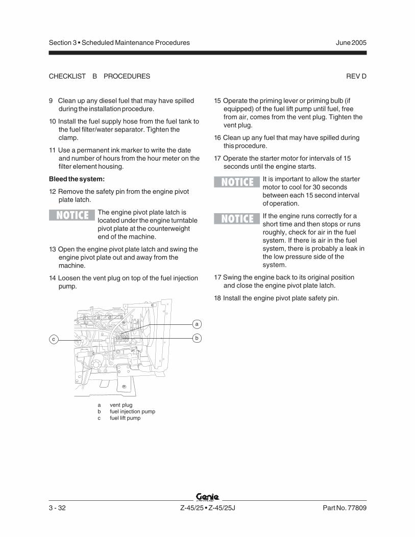
3 - 32 Z-45/25 • Z-45/25J Part No. 77809
June 2005Section 3 • Scheduled Maintenance Procedures
REV D
a
bc
9 Clean up any diesel fuel that may have spilledduring the installation procedure.
10 Install the fuel supply hose from the fuel tank tothe fuel filter/water separator. Tighten theclamp.
11 Use a permanent ink marker to write the dateand number of hours from the hour meter on thefilter element housing.
Bleed the system:
12 Remove the safety pin from the engine pivotplate latch.
The engine pivot plate latch islocated under the engine turntablepivot plate at the counterweightend of the machine.
13 Open the engine pivot plate latch and swing theengine pivot plate out and away from themachine.
14 Loosen the vent plug on top of the fuel injectionpump.
a vent plugb fuel injection pumpc fuel lift pump
15 Operate the priming lever or priming bulb (ifequipped) of the fuel lift pump until fuel, freefrom air, comes from the vent plug. Tighten thevent plug.
16 Clean up any fuel that may have spilled duringthis procedure.
17 Operate the starter motor for intervals of 15seconds until the engine starts.
It is important to allow the startermotor to cool for 30 secondsbetween each 15 second intervalof operation.
If the engine runs correctly for ashort time and then stops or runsroughly, check for air in the fuelsystem. If there is air in the fuelsystem, there is probably a leak inthe low pressure side of thesystem.
17 Swing the engine back to its original positionand close the engine pivot plate latch.
18 Install the engine pivot plate safety pin.
CHECKLIST B PROCEDURES
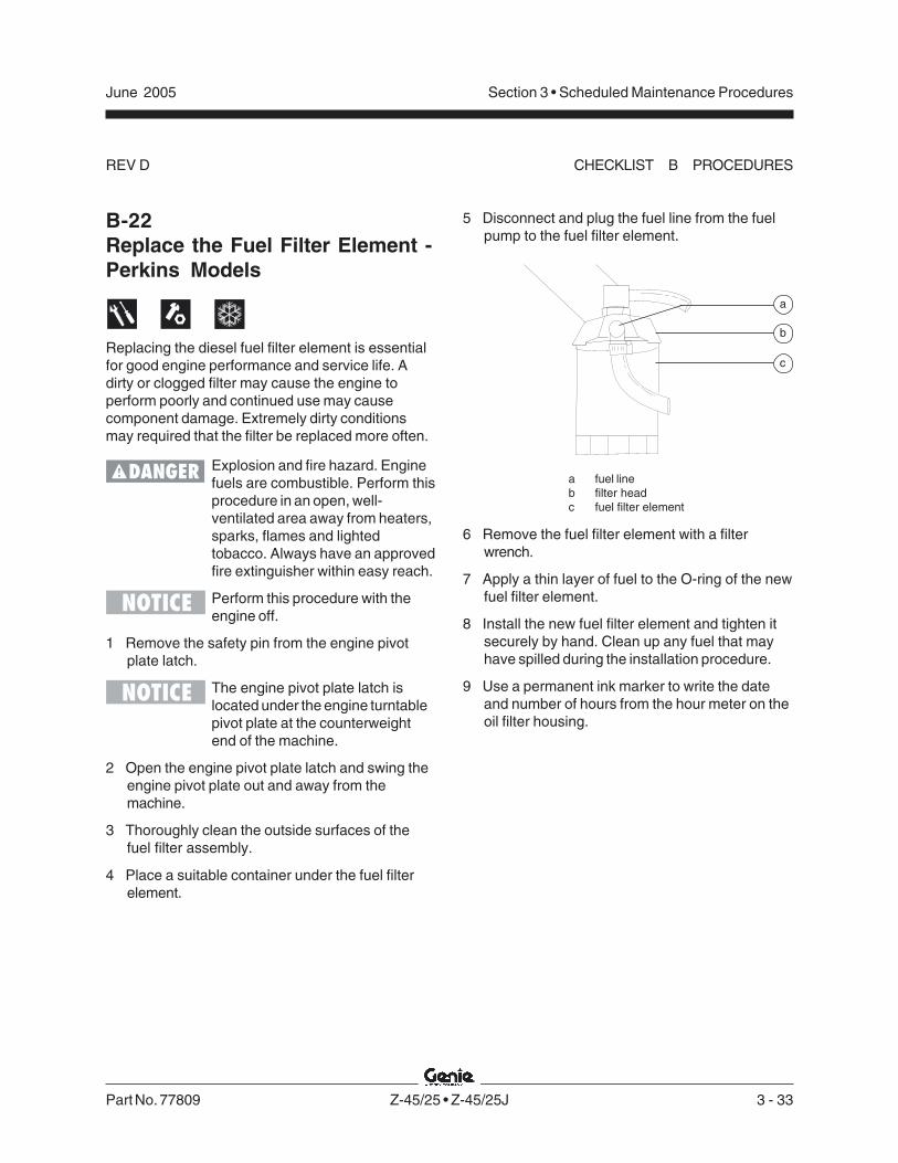
Part No. 77809 Z-45/25 • Z-45/25J 3 - 33
June 2005 Section 3 • Scheduled Maintenance Procedures
REV D
B-22Replace the Fuel Filter Element -Perkins Models
Replacing the diesel fuel filter element is essentialfor good engine performance and service life. Adirty or clogged filter may cause the engine toperform poorly and continued use may causecomponent damage. Extremely dirty conditionsmay required that the filter be replaced more often.
Explosion and fire hazard. Enginefuels are combustible. Perform thisprocedure in an open, well-ventilated area away from heaters,sparks, flames and lightedtobacco. Always have an approvedfire extinguisher within easy reach.
Perform this procedure with theengine off.
1 Remove the safety pin from the engine pivotplate latch.
The engine pivot plate latch islocated under the engine turntablepivot plate at the counterweightend of the machine.
2 Open the engine pivot plate latch and swing theengine pivot plate out and away from themachine.
3 Thoroughly clean the outside surfaces of thefuel filter assembly.
4 Place a suitable container under the fuel filterelement.
5 Disconnect and plug the fuel line from the fuelpump to the fuel filter element.
a fuel lineb filter headc fuel filter element
6 Remove the fuel filter element with a filterwrench.
7 Apply a thin layer of fuel to the O-ring of the newfuel filter element.
8 Install the new fuel filter element and tighten itsecurely by hand. Clean up any fuel that mayhave spilled during the installation procedure.
9 Use a permanent ink marker to write the dateand number of hours from the hour meter on theoil filter housing.
CHECKLIST B PROCEDURES
b
a
c

3 - 34 Z-45/25 • Z-45/25J Part No. 77809
June 2005Section 3 • Scheduled Maintenance Procedures
REV D
Bleed the fuel system:
9 Loosen the vent plug on top of the fuel injectionpump.
a vent plugb fuel injection pumpc fuel lift pump
10 Operate the priming lever or priming bulb (ifequipped) of the fuel lift pump until fuel, freefrom air, comes from the vent plug. Tighten thevent plug.
11 Clean up any fuel that may have spilled duringthis procedure.
12 Operate the starter motor for intervals of 15seconds until the engine starts.
It is important to allow the startermotor to cool for 30 secondsbetween each 15 second intervalof operation.
If the engine runs correctly for ashort time and then stops or runsroughly, check for air in the fuelsystem. If there is air in the fuelsystem, there is probably a leak inthe low pressure side of thesystem.
B-23Perform Engine Maintenance -Deutz Models
Deutz engine specifications requirethat this procedure be performedevery 400 hours.
Proper engine maintenance, following the enginemanufacturer's maintenance schedule, is essentialto good engine performance and service life. Failureto perform the maintenance procedures can lead topoor engine performance and component damage.
Required maintenance procedures and additionalengine information are available in theDeutz FL 1011F Operation Manual(Deutz part number 0297 9683).
Deutz FL 1011F Operation ManualGenie part number 52883
To access the engine:
1 Remove the safety pin from the engine pivotplate latch.
The engine pivot plate latch islocated under the engine turntablepivot plate at the counterweightend of the machine.
2 Open the engine pivot plate latch and swing theengine pivot plate out and away from themachine.
CHECKLIST B PROCEDURES
a
bc

Part No. 77809 Z-45/25 • Z-45/25J 3 - 35
June 2005 Section 3 • Scheduled Maintenance Procedures
REV D
B-24Perform Engine Maintenance -Ford Models
Ford engine specifications requirethat this procedure be performedevery 400 hours.
Proper engine maintenance, following the enginemanufacturer's maintenance schedule, is essentialto good engine performance and service life. Failureto perform the maintenance procedures can lead topoor engine performance and component damage.
Required maintenance procedures and additionalengine information are available in theFord LRG-425 EFI Operator Handbook(Ford part number FPP 194-302).
Ford LRG-425 EFI Operator HandbookGenie part number 84792
To access the engine:
1 Remove the safety pin from the engine pivotplate latch.
The engine pivot plate latch islocated under the engine turntablepivot plate at the counterweightend of the machine.
2 Open the engine pivot plate latch and swing theengine pivot plate out and away from themachine.
B-25Perform Engine Maintenance -Perkins Models
Perkins engine specificationsrequire that this procedure beperformed every 400 hours.
Proper engine maintenance, following the enginemanufacturer's maintenance schedule, is essentialto good engine performance and service life. Failureto perform the maintenance procedures can lead topoor engine performance and component damage.
Required maintenance procedures and additionalengine information are available in thePerkins 100 Series Workshop Manual(Perkins part number TPD 1377E).
Perkins 100 Series Workshop ManualGenie part number 72352
To access the engine:
1 Remove the safety pin from the engine pivotplate latch.
The engine pivot plate latch islocated under the engine turntablepivot plate at the counterweightend of the machine.
2 Open the engine pivot plate latch and swing theengine pivot plate out and away from themachine.
CHECKLIST B PROCEDURES
3 - 36 Z-45/25 • Z-45/25J Part No. 77809
June 2005Section 3 • Scheduled Maintenance Procedures
REV C
C-1Perform Engine Maintenance -Deutz Models
Deutz engine specifications requirethat this procedure be performedevery 500 hours.
Proper engine maintenance, following the enginemanufacturer's maintenance schedule, is essentialto good engine performance and service life. Failureto perform the maintenance procedures can lead topoor engine performance and component damage.
Required maintenance procedures and additionalengine information are available in theDeutz FL 1011F Operation Manual(Deutz part number 0297 9683).
Deutz FL 1011F Operation ManualGenie part number 52883
To access the engine:
1 Remove the safety pin from the engine pivotplate latch.
The engine pivot plate latch islocated under the engine turntablepivot plate at the counterweightend of the machine.
2 Open the engine pivot plate latch and swing theengine pivot plate out and away from themachine.
Checklist C Procedures
C-2Grease the Platform OverloadMechanism (if equipped)
Genie specifications requirethat this procedure be performedevery 500 hours or 6 months,whichever comes first. Performthis procedure more often if dustyconditions exist.
Application of lubrication to the platform overloadmechanism is essential to safe machine operation.Continued use of an improperly greased platformoverload mechanism could result in the system notsensing an overloaded platform condition and willresult in component damage.
1 Locate the grease fittings on each pivot pin ofthe platform overload assembly.
2 Thoroughly pump grease into each grease fittingusing a mulit-purpose grease.

Part No. 77809 Z-45/25 • Z-45/25J 3 - 37
June 2005 Section 3 • Scheduled Maintenance Procedures
REV C
C-3Test the Platform OverloadSystem (if equipped)
Genie specifications require thatthis procedure be performed every500 hours or six months.
Testing the platform overload system regularly isessential to safe machine operation. Continued useof an improperly operating platform overloadsystem could result in the system not sensing anoverloaded platform condition. Machine stablitycould be compromised resulting in the machinetipping over.
Perform this procedure with themachine on a firm, level surface.
1 Turn the key switch to platform control. Start theengine from the platform controls.
2 Level the platform.
3 Determine the maximum platform capacity.Refer to the machine serial plate.
4 Using a suitable lifting device, place anappropriate test weight equal to that of themaximum platform capacity in one of thelocations shown.
Result: The platform overload indicator lightshould be off at both the ground and platformcontrols.
5 Carefully move the test weight to eachremaining location.
Result: The platform overload indicator lightshould be off at both the ground and platformcontrols.
6 Add an additional 66 lbs / 30 kg of weight tooverload the platform.
Result: The alarm should be sounding.The platform overload indicator light should beflashing at both the ground and platformcontrols.
Result: If the alarm does not sound and theplatform overload indicator light does not comeon with the test weights in any of the platformlocations, the platform overload system needsto be calibrated. See D-8, Calibrate the PlatformOverload System.
There may be an approximate 2second delay before the overloadindicator light turns on and thealarm sounds.
CHECKLIST C PROCEDURES

3 - 38 Z-45/25 • Z-45/25J Part No. 77809
June 2005Section 3 • Scheduled Maintenance Procedures
REV C
7 Carefully move the test weights to eachremaining location in the platform.
Result: The alarm should be sounding.The platform overload indicator light should beflashing at both the ground and platformcontrols.
Result: If the alarm does not sound and theplatform overload indicator light does not comeon with the test weights in any of the platformlocations, the platform overload system needsto be calibrated. See D-8, Calibrate the PlatformOverload System.
There may be an approximate 2second delay before the overloadindicator light turns on and thealarm sounds.
8 Test all machine functions from the platformcontrols.
Result: All platform control functions should notoperate.
9 Turn the key switch to ground control.
10 Test all machine functions from the groundcontrols.
Result: All ground control functions should notoperate.
Machine functions should stilloperate with auxiliary power at theground controls.
11 Lift the test weights off the platform floor using asuitable lifting device.
Result: The platform overload indicator light andalarm should turn off at both the ground andplatform controls.
There may be an approximate 2second delay before the overloadindicator light and alarm turn off.
12 Test all machine functions from the groundcontrols.
Result: All ground control functions shouldoperate normally.
13 Turn the key switch to platform control.
14 Test all machine functions from the platformcontrols.
Result: All platform control functions shouldoperate.
If the platform overload system isnot operating properly, see D-8,Calibrate the Platform OverloadSystem.
CHECKLIST C PROCEDURES

Part No. 77809 Z-45/25 • Z-45/25J 3 - 39
June 2005 Section 3 • Scheduled Maintenance Procedures
REV C
C-4Perform Engine Maintenance -Perkins Models
Perkins engine specificationsrequire that this procedure beperformed every 600 hours.
Proper engine maintenance, following the enginemanufacturer's maintenance schedule, is essentialto good engine performance and service life. Failureto perform the maintenance procedures can lead topoor engine performance and component damage.
Required maintenance procedures and additionalengine information are available in thePerkins 100 Series Workshop Manual(Perkins part number TPD 1377E).
Perkins 100 Series Workshop ManualGenie part number 72352
To access the engine:
1 Remove the safety pin from the engine pivotplate latch.
The engine pivot plate latch islocated under the engine turntablepivot plate at the counterweightend of the machine.
2 Open the engine pivot plate latch and swing theengine pivot plate out and away from themachine.
C-5Perform Engine Maintenance -Ford Models
Ford engine specifications requirethat this procedure be performedevery 800 hours.
Proper engine maintenance, following the enginemanufacturer's maintenance schedule, is essentialto good engine performance and service life. Failureto perform the maintenance procedures can lead topoor engine performance and component damage.
Required maintenance procedures and additionalengine information are available in theFord LRG-425 EFI Operator Handbook(Ford part number FPP 194-302).
Ford LRG-425 EFI Operator HandbookGenie part number 84792
To access the engine:
1 Remove the safety pin from the engine pivotplate latch.
The engine pivot plate latch islocated under the engine turntablepivot plate at the counterweightend of the machine.
2 Open the engine pivot plate latch and swing theengine pivot plate out and away from themachine.
CHECKLIST C PROCEDURES

3 - 40 Z-45/25 • Z-45/25J Part No. 77809
June 2005Section 3 • Scheduled Maintenance Procedures
REV DChecklist D Procedures
D-1Check the BoomWear Pads
Maintaining the boom wear pads in good conditionis essential to safe machine operation. Wear padsare placed on boom tube surfaces to provide a lowfriction, replaceable wear pad between movingparts. Improperly shimmed wear pads or continueduse of worn out wear pads may result in componentdamage and unsafe operating conditions.
1 Start the engine from the ground controls.
2 Raise the end of the primary boom to acomfortable working height (chest high), thenextend the boom 1 foot / 30 cm.
3 Measure each wear pad. Replace the wear pad ifit is less than 9/16 inch / 14.3 mm. If the wearpad is not less than 9/16 inch / 14.3 mm, shimas necessary to obtain zero clearance and zerodrag.
4 Extend and retract the primary boom through theentire range of motion to check for tight spotsthat may cause binding or scraping of the boom.
Always maintain squarenessbetween the outer and innerboom tubes.
Wear pad specifications
All wear pads 9/16 inch14.3 mm
D-2Check the Turntable RotationBearing Bolts
Maintaining proper torque on the turntable bearingbolts is essential to safe machine operation.Improper bolt torque could result in an unsafeoperating condition and component damage.
1 Raise the secondary boom and place safetychocks on the lift cylinders rods. Carefully lowerthe boom onto the lift cylinder safety chocks.
Crushing hazard. Keep handsaway from cylinders and all movingparts when lowering the boom.
The lift cylinder safety chock isavailable through Genie ServiceParts.
2 Turn the engine off.
3 Remove the safety pin from the engine pivotplate latch.
The engine pivot plate latch islocated under the engine turntablepivot plate at the counterweightend of the machine.
4 Open the engine pivot plate latch and swing theengine pivot plate out and away from themachine.

Part No. 77809 Z-45/25 • Z-45/25J 3 - 41
June 2005 Section 3 • Scheduled Maintenance Procedures
REV D
5 Be sure that each turntable mounting bolt istorqued in sequence to 210 ft-lbs / 285 Nm.
Bolt torque sequence(before serial number 23332)
Bolt torque sequence(after serial number 23331)
6 Start the engine from the ground controls.
7 Raise the secondary boom and remove thesafety chocks.
8 Lower the boom to the stowed position.
9 Remove drive chassis covers from both thesteer end and the non-steer end of the machine.
10 Remove the lower chassis cover mountingfasteners from inside of the drive chassis (ifequipped).
11 Remove the lower chassis cover to access thelower turntable bearing bolts under the drivechassis.
12 Check to ensure that each lower bearingmounting bolt under the drive chassis is torquedin sequence to 210 ft-lbs / 285 Nm.
Bolt torque sequence(before serial number 23332)
Bolt torque sequence(after serial number 23331)
CHECKLIST D PROCEDURES
191510
136
18
3
11
8
2016 2 9
145
17
4
12
7
1
115
7
12
4
5
14
9216
8
3
11
6
1310

3 - 42 Z-45/25 • Z-45/25J Part No. 77809
June 2005Section 3 • Scheduled Maintenance Procedures
REV D
disengaged position
engaged position
disengaged position
engaged position
D-3Check the Free-wheelConfiguration
Proper use of the free-wheel configuration isessential to safe machine operation. Thefree-wheel configuration is used primarily for towing.A machine configured to free-wheel without operatorknowledge may cause death or serious injury andproperty damage.
Collision hazard. Select a work sitethat is firm and level.
Component damage hazard. If themachine must be towed, do notexceed 2 mph / 3.2 km/h.
Non-steer wheels: All models
1 Chock the steer wheels to prevent the machinefrom rolling.
2 Center a lifting jack of ample capacity(20,000 lbs / 10,000 kg) under the drive chassisbetween the non-steer tires.
3 Lift the wheels off the ground and then placejack stands under the drive chassis for support.
4 Disengage the drive hubs by turning over thedrive hub disconnect caps on eachnon-steer wheel hub.
5 Manually rotate each non-steer wheel.
Result: Each non-steer wheel should rotate withminimum effort.
6 Re-engage the drive hubs by turning overthe hub disconnect caps. Rotate each wheel tocheck for engagement. Lift the machine andremove the jack stands.
Collision hazard. Failure tore-engage the drive hubs maycause death or serious injury andproperty damage.
Steer wheels: 4WD models
7 Chock the non-steer wheels to prevent themachine from rolling.
8 Center a lifting jack of ample capacity(20,000 lbs / 10,000 kg) under the drive chassisbetween the steer tires.
9 Lift the wheels off the ground and then placejack stands under the drive chassis for support.
10 Disengage the drive hubs by turning over thedrive hub disconnect caps on eachsteer wheel hub.
CHECKLIST D PROCEDURES
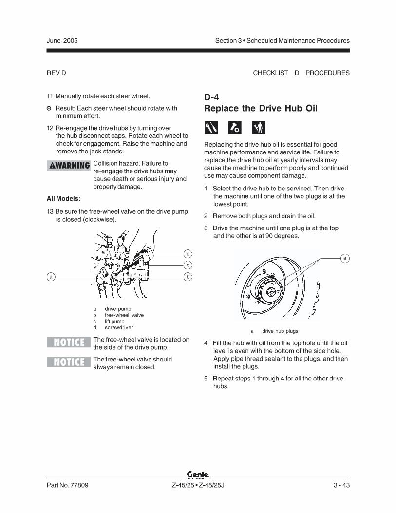
Part No. 77809 Z-45/25 • Z-45/25J 3 - 43
June 2005 Section 3 • Scheduled Maintenance Procedures
REV D
11 Manually rotate each steer wheel.
Result: Each steer wheel should rotate withminimum effort.
12 Re-engage the drive hubs by turning overthe hub disconnect caps. Rotate each wheel tocheck for engagement. Raise the machine andremove the jack stands.
Collision hazard. Failure tore-engage the drive hubs maycause death or serious injury andproperty damage.
All Models:
13 Be sure the free-wheel valve on the drive pumpis closed (clockwise).
a drive pumpb free-wheel valvec lift pumpd screwdriver
The free-wheel valve is located onthe side of the drive pump.
The free-wheel valve shouldalways remain closed.
D-4Replace the Drive Hub Oil
Replacing the drive hub oil is essential for goodmachine performance and service life. Failure toreplace the drive hub oil at yearly intervals maycause the machine to perform poorly and continueduse may cause component damage.
1 Select the drive hub to be serviced. Then drivethe machine until one of the two plugs is at thelowest point.
2 Remove both plugs and drain the oil.
3 Drive the machine until one plug is at the topand the other is at 90 degrees.
a drive hub plugs
4 Fill the hub with oil from the top hole until the oillevel is even with the bottom of the side hole.Apply pipe thread sealant to the plugs, and theninstall the plugs.
5 Repeat steps 1 through 4 for all the other drivehubs.
CHECKLIST D PROCEDURES
a b
c
da

3 - 44 Z-45/25 • Z-45/25J Part No. 77809
June 2005Section 3 • Scheduled Maintenance Procedures
REV D
D-5Check and Adjust the Air/LPGMixture - Ford Models
Maintaining the proper air-to-fuel mixture duringLPG operation is essential to good engineperformance.
Explosion and fire hazard. Enginefuels are combustible. Perform thisprocedure in an open, well-ventilated area away from heaters,sparks, flames and lightedtobacco. Always have an approvedfire extinguisher within easy reach.
The engine should be warmed tonormal operating temperaturebefore performing this procedure.
1 Move the fuel select toggle switch to LPG fueland start the engine from the ground controls.
2 Locate the high idle mixture adjustmentscrew on the LPG venturi that attaches to theair cleaner air cleaner hose.
3 Loosen the lock nut on the high idle mixtureadjustment screw.
4 Load the system by activating the primary boomretract function and moving the function enabletoggle switch to the high idle (rabbit symbol)position.
5 Adjust the high idle adjustment screw to obtainan air-to-fuel mixture ratio of 13:1 to 13.2:1,using an exhaust gas analyzer.
Preliminary setting is 1/4 inch /6.4 mm of threads showing.Measure from the top of the locknut to the top of the adjustmentscrew.
If an exhaust gas analyzer is notavailable, adjust to obtain peak oroptimum rpm.
6 Hold the adjustment screw and tighten thelock nut.
7 Return the function enable toggle switch to thecenter position.
8 Locate the low idle mixture adjustment screw onthe LPG regulator.
9 Adjust the low idle mixture adjustment screw toobtain an air-to-fuel mixture ratio of 13:1 to13.2:1.
Preliminary setting: turn low idleadjustment screw clockwise all theway in. Turn low idle adjustmentscrew counterclockwise 2 3/4turns.
CHECKLIST D PROCEDURES

Part No. 77809 Z-45/25 • Z-45/25J 3 - 45
June 2005 Section 3 • Scheduled Maintenance Procedures
REV D
D-6Perform Engine Maintenance -Deutz Models
Deutz engine specifications requirethat this procedure be performedevery 1000 hours.
Proper engine maintenance, following the enginemanufacturer's maintenance schedule, is essentialto good engine performance and service life. Failureto perform the maintenance procedures can lead topoor engine performance and component damage.
Required maintenance procedures and additionalengine information are available in theDeutz FL 1011F Operation Manual(Deutz part number 0297 9683).
Deutz FL 1011F Operation ManualGenie part number 52883
To access the engine:
1 Remove the safety pin from the engine pivotplate latch.
The engine pivot plate latch islocated under the engine turntablepivot plate at the counterweightend of the machine.
2 Open the engine pivot plate latch and swing theengine pivot plate out and away from themachine.
CHECKLIST D PROCEDURES
D-7Inspect for Turntable BearingWear
Periodic inspection of turntable bearing wear isessential to safe machine operation, good machineperformance and service life. Continued use of aworn turntable bearing could create an unsafeoperating condition, resulting in death or seriousinjury and component damage.
Perform this procedure with themachine on a firm, level surfaceand the boom in the stowedposition.
1 Grease the turntable bearing. See A-13, Greasethe Turntable Bearing and Rotate Gear.
2 Torque the turntable bearing bolts tospecification. See D-2, Check the TurntableRotation Bearing Bolts.
3 Start the machine from the ground controls andraise the primary and secondary booms to fullheight. Do not extend the primary boom.

3 - 46 Z-45/25 • Z-45/25J Part No. 77809
June 2005Section 3 • Scheduled Maintenance Procedures
REV D
4 Place a dial indicator between the drive chassisand the turntable at a point that is directlyunder, or inline with, the boom and no more than1 inch / 2.5 cm from the bearing.
To obtain an accuratemeasurement, place the dialindicator no more than 1 inch /2.5 cm from the turntable rotationbearing.
a turntableb dial indicatorc drive chassisd turntable rotation bearing
5 At the dial indicator, adjust it to "zero" theindicator.
6 Lower the secondary boom to the stowedposition and lower the primary boom to ahorizontal position. Fully extend the primaryboom.
CHECKLIST D PROCEDURES
7 Note the reading on the dial indicator.
Result: The measurement is less than0.055 inch / 1.4 mm. The bearing is good.
Result: The measurement is more than0.055 inch / 1.4 mm. The bearing is worn andneeds to be replaced.
8 Fully retract the primary boom. Raise theprimary and secondary booms to full height.Visually inspect the the dial indicator to be surethe needle returns to the "zero" position.
9 Remove the dial indicator and rotate theturntable 90°.
10 Repeat steps 4 through 9 until the rotationbearing has been checked in at least fourequally spaced areas 90° apart.
11 Lower the primary and secondary booms to thestowed position and turn the machine off.
12 Remove the dial indicator from the machine.
a
b
c
d

Part No. 77809 Z-45/25 • Z-45/25J 3 - 47
June 2005 Section 3 • Scheduled Maintenance Procedures
REV D
D-8Calibrate the Platform OverloadSystem (if equipped)
Genie specifications require thatthis procedure be performed every1000 hours of operation or yearly.
Yearly calibration of the platform overload systemis essential to safe machine operation. Continueduse of an improperly calibrated platform overloadsystem could result in the system failing to sensean overloaded platform. The stability of themachine is compromised and it could tip over.
Perform this procedure with themachine on a firm, level surface.
1 Level the platform.
2 Determine the maximum platform capacity.Refer to the machine serial plate.
3 Using a suitable lifting device, place anappropriate test weight equal to that of themaximum platform capacity at the center of theplatform floor.
Determine the limit switch trigger point:
4 Gently move the platform up and down by hand,so it bounces approximately 2.5 to 5 cm. Allowthe platform to settle.
Result: The overload indicator light and thealarm is on. Slowly tighten the load springadjustment nut by turning it clockwise just untilthe overload indicator light and alarm turns off.
The platform will need to be movedup and down and allowed to settlein between adjustments.
There may be an approximate 2second delay before the overloadindicator light turns on and thealarm sounds.
Result: The overload indicator light andalarm is off. Slowly loosen the load springadjustment nut by turning it counterclockwisejust until the overload indicator light and alarmturn on.
There may be an approximate 2second delay before the overloadindicator light turns on and thealarm sounds.
The platform will need to be movedup and down and allowed to settlein between adjustments.
CHECKLIST D PROCEDURES
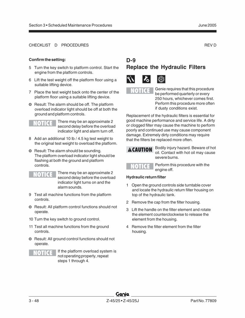
3 - 48 Z-45/25 • Z-45/25J Part No. 77809
June 2005Section 3 • Scheduled Maintenance Procedures
REV D
Confirm the setting:
5 Turn the key switch to platform control. Start theengine from the platform controls.
6 Lift the test weight off the platform floor using asuitable lifting device.
7 Place the test weight back onto the center of theplatform floor using a suitable lifting device.
Result: The alarm should be off. The platformoverload indicator light should be off at both theground and platform controls.
There may be an approximate 2second delay before the overloadindicator light and alarm turn off.
8 Add an additional 10 lb / 4.5 kg test weight tothe original test weight to overload the platform.
Result: The alarm should be sounding.The platform overload indicator light should beflashing at both the ground and platformcontrols.
There may be an approximate 2second delay before the overloadindicator light turns on and thealarm sounds.
9 Test all machine functions from the platformcontrols.
Result: All platform control functions should notoperate.
10 Turn the key switch to ground control.
11 Test all machine functions from the groundcontrols.
Result: All ground control functions should notoperate.
If the platform overload system isnot operating properly, repeatsteps 1 through 4.
CHECKLIST D PROCEDURES
D-9Replace the Hydraulic Filters
Genie requires that this procedurebe performed quarterly or every250 hours, whichever comes first.Perform this procedure more oftenif dusty conditions exist.
Replacement of the hydraulic filters is essential forgood machine performance and service life. A dirtyor clogged filter may cause the machine to performpoorly and continued use may cause componentdamage. Extremely dirty conditions may requirethat the filters be replaced more often.
Bodily injury hazard. Beware of hotoil. Contact with hot oil may causesevere burns.
Perform this procedure with theengine off.
Hydraulic return filter
1 Open the ground controls side turntable coverand locate the hydraulic return filter housing ontop of the hydraulic tank.
2 Remove the cap from the filter housing.
3 Lift the handle on the filter element and rotatethe element counterclockwise to release theelement from the housing.
4 Remove the filter element from the filterhousing.
Part No. 77809 Z-45/25 • Z-45/25J 3 - 49
June 2005 Section 3 • Scheduled Maintenance Procedures
REV D
5 Install the new filter element into the filterhousing.
6 Push the filter element down to be sure the o-ring on the element is fully seated into thehousing.
7 Rotate the filter element clockwise to lock it inplace.
8 Install the filter housing cap.
9 Use a permanent ink marker to write the dateand number of hours from the hour meter on theoil filter housing.
Medium and high pressure filters
The medium pressure filter is forthe charge pump and the highpressure filter is for all machinefunctions except the drive circuitand oscillating axle circuit.
10 Open the engine side turntable cover and locatethe medium and high pressure filters.
The medium pressure filter ismounted near the pump. The highpressure filter, with filter conditionindicator, is mounted to thebulkhead.
11 Place a suitable container under each filter.
12 Remove the filter housings by using a wrench onthe nut provided on the bottom of the housings.
13 Remove the filter elements from the housings.
14 Inspect the housing seals and replace them ifnecessary.
15 Install the new filter elements into the housingsand tighten them securely.
The medium and high pressurefilters use the same elements.
16 Clean up any oil that may have spilled during theinstallation procedure.
17 Use a permanent ink marker to write the dateand number of hours from the hour meter on theoil filter housings.
18 Start the engine from the ground controls.
19 Inspect the filter housings and relatedcomponents to be sure that there are no leaks.
CHECKLIST D PROCEDURES

3 - 50 Z-45/25 • Z-45/25J Part No. 77809
June 2005Section 3 • Scheduled Maintenance Procedures
REV B
3 Models with hydraulic tank shut-off valves:Locate the two hydraulic tank valves at thehydraulic tank through the access holeunderneath the turntable. Close the valves.
Component damage hazard. Theengine must not be started with thehydraulic tank shut-off valves inthe closed position or componentdamage will occur. If the tankvalves are closed, remove the keyfrom the key switch and tag themachine to inform personnel of thecondition.
3 Place a suitable container underneath thehydraulic tank.
4 Remove the drain plug from the hydraulic tank.
5 Completely drain the tank into a suitablecontainer. See capacity specifications.
6 Tag, disconnect and plug the two suction hosesand supply hose for the auxiliary pump from thehydraulic tank. Cap the fittings on the tank.
The hoses can be accessedthrough the access hole under theturntable.
7 Disconnect and plug the return filter hydraulichose at the return filter. Cap the fitting on thefilter housing.
E-1Test or Replace the HydraulicOil
Replacement or testing of the hydraulic oil isessential for good machine performance andservice life. Dirty oil and suction strainers maycause the machine to perform poorly and continueduse may cause component damage. Extremelydirty conditions may require oil changes to beperformed more often.
Before replacing the hydraulic oil,the oil may be tested by an oildistributor for specific levels ofcontamination to verify thatchanging the oil is necessary. Ifthe hydraulic oil is not replacedat the two year inspection, testthe oil quarterly. Replace the oilwhen it fails the test.
Perform this procedure with theboom in the stowed position.
1 Ford models: Turn the valve on the LPG tankclockwise to the off position (if equipped). Thenslowly disconnect the hose from the LPG tank.
2 Ford models: Open the clamps from the LPGtank straps and remove the LPG tank from themachine (if equipped).
Checklist E Procedures
open closed
Part No. 77809 Z-45/25 • Z-45/25J 3 - 51
June 2005 Section 3 • Scheduled Maintenance Procedures
REV B
8 Remove the ground controls side turntablecover.
9 Support the hydraulic tank with an appropriatelifting device.
10 Remove the hydraulic tank mounting fasteners.
11 Remove the hydraulic tank from the machine.
Crushing hazard. The hydraulictank could become unbalancedand fall if not properly supportedwhen removed from the machine.
12 Remove the hydraulic return filter housingmounting fasteners. Remove the hydraulicreturn filter housing from the hydraulic tank.
13 Remove the suction strainers from the tank andclean them using a mild solvent.
14 Rinse out the inside of the tank using a mildsolvent.
15 Install the suction strainers using a threadsealant on the threads.
16 Install the drain plug using a thread sealant onthe threads.
17 Install the hydraulic return filter housing onto thehydraulic tank.
18 Install the hydraulic tank onto the machine.
19 Install the two suction hoses to the suctionstrainers.
20 Install the supply hose for the auxiliary powerunit and the return filter hose.
21 Models with hydraulic tank shut-off valves:Open the two hydraulic tank valves at thehydraulic tank.
22 Fill the tank with the proper hydraulic oil for yourmachine until the level is within the top2 inches / 5 cm of the sight gauge. Do notoverfill. Refer to Section 2, Specifications.
23 Clean up any oil that may have spilled.
24 Prime the pump. Refer to Repair Procedure 7-2,How to Prime the Pump.
Always use pipe thread sealantwhen installing the suction hosefittings and the drain plug.
CHECKLIST E PROCEDURES

3 - 52 Z-45/25 • Z-45/25J Part No. 77809
June 2005Section 3 • Scheduled Maintenance Procedures
REV B
E-2Change the Fuel Hoses -Ford Models
Maintaining the fuel hoses in good condition isessential to safe operation and good engineperformance. Failure to detect a worn, cracked orleaking fuel hose may cause an unsafe operatingcondition.
Explosion and fire hazard. Enginefuels are combustible. Replace thefuel hoses in an open, well-ventilated area away from heaters,sparks, flames and lightedtobacco. Always have an approvedfire extinguisher within easy reach.
Component damage hazard. Besure the fuel hoses are routed thesame way the original hoses were.
Perform this procedure with theengine off and the key switch inthe off position.
1 Put on protective clothing and eye wear.
2 Open the tank side turntable cover and locatethe fuel system components mounted to theplate under the fuel tank.
3 Remove the fuel system plate retainingfasteners. Carefully lower the fuel system plate.
4 At the pre-filter, disconnect and drain the fueltank into a suitable container. See capacityspecifications.
5 Remove and replace all of the fuel line hosesand clamps according to the followingillustration.
Explosion and fire hazard.Electronic Fuel Injection (EFI)systems operate at a very highpressure. Fuel may be expelledunder pressure if the hoses areremoved too quickly. Loosen thefuel lines very slowly to allow thefuel pressure to dissipategradually. Wrap a cloth around fuelhoses to absorb leaking fuel beforedisconnecting them.
6 Clean up any fuel that may have spilled duringthis procedure.
7 Start the engine from the ground controls, theninspect the fuel filter and hoses for leaks.
Explosion and fire hazard. If a fuelleak is discovered, keep anyadditional personnel from enteringthe area and do not operate themachine. Repair the leakimmediately.
CHECKLIST E PROCEDURES
Fuel Pump
Fuel pressureregulator/filter
Pre-Filter
“To engine”
“From tank”
“Return to tank”

Part No. 77809 Z-45/25 • Z-45/25J 3 - 53
June 2005 Section 3 • Scheduled Maintenance Procedures
REV B
E-4Grease the Steer AxleWheel Bearings, 2WD Models
Maintaining the steer axle wheel bearings isessential for safe machine operation and servicelife. Operating the machine with loose or wornwheel bearings may cause an unsafe operatingcondition and continued use may result incomponent damage. Extremely wet or dirtyconditions or regular steam cleaning and pressurewashing of the machine may require that thisprocedure be performed more often.
1 Loosen the wheel lug nuts. Do not remove them.
2 Block the non-steer wheels, then center a liftingjack under the steer axle.
3 Raise the machine 6 inches / 15 cm and placeblocks under the drive chassis for support.
4 Remove the lug nuts. Remove the tire and wheelassembly.
5 Check for wheel bearing wear by attempting tomove the wheel hub side to side, then up anddown.
Result: There should be no side to side or upand down movement.
Skip to step 10 if there is no movement.
E-3Perform Engine Maintenance -Deutz Models
Deutz engine specifications requirethat this procedure be performedevery 3000 hours.
Proper engine maintenance, following the enginemanufacturer's maintenance schedule, is essentialto good engine performance and service life. Failureto perform the maintenance procedures can lead topoor engine performance and component damage.
Required maintenance procedures and additionalengine information are available in theDeutz FL 1011F Workshop Manual(Deutz part number: 0297 7195).
Deutz FL 1011F Workshop ManualGenie part number 52229
To access the engine:
1 Remove the safety pin from the engine pivotplate latch.
The engine pivot plate latch islocated under the engine turntablepivot plate at the counterweightend of the machine.
2 Open the engine pivot plate latch and swing theengine pivot plate out and away from themachine.
CHECKLIST E PROCEDURES

3 - 54 Z-45/25 • Z-45/25J Part No. 77809
June 2005Section 3 • Scheduled Maintenance Procedures
REV B
14 Pack both bearings with clean, fresh grease.
15 Place the large inner bearing into the rear of thehub.
16 Install a new bearing grease seal into the hub bypressing it evenly into the hub until it is flush.
17 Slide the hub onto the yoke spindle.
Component damage hazard. Donot apply excessive force ordamage to the lip of the seal mayoccur.
18 Place the outer bearing into the hub.
19 Install the washer and castle nut.
20 Tighten the slotted nut to 35 ft-lbs / 47 Nm toseat the bearings.
21 Loosen the castle nut and re-tighten to8 ft-lbs / 11 Nm.
22 Install a new cotter pin. Bend the cotter pinto lock it in.
Always use a new cotter pin wheninstalling a castle nut.
23 Install the dust cap, then the tire and wheelassembly. Torque the wheel lug nuts tospecification. Refer to Section 2, Specifications.
6 Remove the dust cap from the hub. Remove thecotter pin from the castle nut.
7 Tighten the castle nut to 35 ft-lbs / 47 Nm toseat the bearings.
8 Loosen the castle nut and re-tighten to8 ft-lbs / 11 Nm.
9 Check for wheel bearing wear by attempting tomove the wheel hub side to side, then up anddown.
Result: If there is side to side or up and downmovement, continue to step 11 and replace thewheel bearings with new ones.
When replacing a wheel bearing,both the inner and outer bearings,including the pressed-in races,must be replaced.
Result: If there is no side to side or up anddown movement, continue with step 11 andgrease the wheel bearings.
10 Remove the dust cap from the hub. Remove thecotter pin from the castle nut.
11 Remove the castle nut.
12 Pull the hub off of the spindle. The washer andouter bearing should fall loose from the hub.
13 Place the hub on a flat surface and gently prythe bearing seal out of the hub. Remove the rearbearing.
CHECKLIST E PROCEDURES

Part No. 77809 Genie Z-45/25 and Genie Z-45/25J 4 - 1
March 2005 Section 4 • Repair Procedures
Repair Procedures
Observe and Obey:Repair procedures shall be completed by aperson trained and qualified on the repair of thismachine.
Immediately tag and remove from service adamaged or malfunctioning machine.
Repair any machine damage or malfunctionbefore operating the machine.
Before Repairs Start:Read, understand and obey the safety rulesand operating instructions in the Genie Z-45/25and Genie Z-45/25J Operator’s Manual on yourmachine.
Be sure that all necessary tools and parts areavailable and ready for use.
Read each procedure completely and adhereto the instructions. Attempting shortcuts mayproduce hazardous conditions.
Unless otherwise specified, perform eachrepair procedure with the machine in thefollowing configuration:
· Machine parked on a firm, level surface
· Boom in stowed position
· Turntable rotated with the boom between the non-steer wheels
· Turntable secured with the turntable rotation lock
· Key switch in the off position with the key removed
· Wheels chocked
· All external AC power supply disconnectedfrom the machine
About This SectionMost of the procedures in this section should onlybe performed by a trained service professionalin a suitably equipped workshop. Select theappropriate repair procedure after troubleshootingthe problem.
Perform disassembly procedures to the pointwhere repairs can be completed. To re-assemble,perform the disassembly steps in reverse order.
Symbols Legend
Safety alert symbol—used to alertpersonnel to potential personalinjury hazards. Obey all safetymessages that follow this symbolto avoid possible injury or death.
Used to indicate the presence ofan imminently hazardous situationwhich, if not avoided, will result indeath or serious injury.
Used to indicate the presence of apotentially hazardous situationwhich, if not avoided, could resultin death or serious injury.
With safety alert symbol—used toindicate the presence of apotentially hazardous situationwhich, if not avoided, may causeminor or moderate injury.
Without safety alert symbol—usedto indicate the presence of apotentially hazardous situationwhich, if not avoided, may result inproperty damage.
Used to indicate operation ormaintenance information.
Indicates that a specific result is expected afterperforming a series of steps.
Indicates that an incorrect result has occurredafter performing a series of steps.

4 - 2 Genie Z-45/25 and Genie Z-45/25J Part No. 77809
March 2005Section 4 • Repair Procedures
REV C
The platform control box contains one printedcircuit board. The ALC-500 circuit board inside theplatform control box controls all proportionalmachine functions from the platform. The joystickcontrollers at the platform controls utilize HallEffect technology (non-contact) and require noadjustment. The operating parameters of thejoysticks are stored in memory at the ECM circuitboard at the platform controls. If a joystick erroroccurs or if a joystick is replaced, it will need to becalibrated before that particular machine functionwill operate. See 1-2, How to Calibrate a Joystick.
Each joystick controller should operate smoothlyand provide proportional speed control over itsentire range of motion.
For further information or assistance, consult theGenie Industries Service Department.
a ALC-500 circuit boardb drive/steer joystick controllerc secondary boom up/down
joystick controllerd primary boom up/down and
turntable rotate left/rightjoystick controller
1-1ALC-500 Circuit Board
Electrocution hazard. Contactwith electrically charged circuitscould result in death or seriousinjury. Remove all rings, watchesand other jewelry.
When the ALC-500 circuit board isreplaced, the joystick controllerswill need to be calibrated. See 1-2,How to Calibrate a Joystick.
How to Remove the ALC-500Circuit Board1 Push in the red Emergency Stop button to the off
position at both the ground and platform controls.
2 Remove the platform control box lid retainingfasteners. Open the control box lid.
3 Locate the ALC-500 circuit board mounted to theinside of the platform control box.
Electrocution hazard. Contact withelectrically charged circuits couldresult in death or serious injury.Remove all rings, watches andother jewelry.
Platform Controls
bcd
a

Part No. 77809 Genie Z-45/25 and Genie Z-45/25J 4 - 3
March 2005 Section 4 • Repair Procedures
REV C
1-2Joysticks
How to Calibrate a JoystickThe joysticks on this machine utilize digital HallEffect technology for proportional control. If ajoystick is disconnected or replaced, it must becalibrated before that particular machine functionwill operate.
The joystick must be calibratedbefore the threshold, max-out orramping can be set.
Perform this procedure with theengine off.
1 Pull out the red Emergency Stop button to theon position at both the ground and platformcontrols.
2 Turn the key switch to platform control. Do notstart the engine.
3 Select a joystick to calibrate.
4 Move the joystick full stroke in either directionand hold for 5 seconds.
5 Return the joystick to the neutral position, pausefor a moment, then move the joystick full strokein the opposite direction. Hold for 5 seconds andreturn the joystick to the neutral position.
Result: The alarm should sound indicatingsuccessful joystick calibration.
6 Repeat this procedure for each joystickcontrolled machine function including the thumbrocker steer switch.
No machine fuction should operatewhile performing the joystickcalibration procedure.
4 Attach a grounded wrist strap to the groundscrew inside the platform control box.
Component damage hazard.Electrostatic discharge (ESD) candamage printed circuit boardcomponents. Maintain firm contactwith a metal part of the machinethat is grounded at all times whenhandling printed circuit boards ORuse a grounded wrist strap.
5 Carefully disconnect the wire connectors fromthe circuit board.
6 Remove the ALC-500 circuit board mountingfasteners.
7 Carefully remove the ALC-500 circuit board fromthe platform control box.
PLATFORM CONTROLS

4 - 4 Genie Z-45/25 and Genie Z-45/25J Part No. 77809
March 2005Section 4 • Repair Procedures
REV CPLATFORM CONTROLS
How to Adjust the JoystickMax-out SettingThe max-out setting of a joystick controls themaximum speed of a joystick-controlled machinefunction. Whenever a hydraulic cylinder, drivemotor or hydraulic pump is replaced, the max-outsetting should be adjusted to maintain optimumperformance. The max-out settings on the joystickcan be changed to compensate for hydraulic pumpwear to maintain peak performance from themachine.
Perform this procedure with theboom in the stowed position.
1 Pull out the red Emergency Stop button to theon position at both the ground and platformcontrols.
2 Turn the key switch to platform control. Do notstart the engine.
3 Push in the platform controls red EmergencyStop button to the off position.
4 Do not press down the foot switch.
5 Move and hold the drive enable toggle switch inthe right position and pull out the redEmergency Stop button to the on position.
6 When the alarm sounds, release the driveenable toggle switch.
7 Momentarily activate the drive enable toggleswitch in the right direction 4 times.
Result: There should be a pause and the alarmshould sound 4 times indicating that themachine is in max-out calibration mode.
8 Start the engine from the platform controls andpress down the foot switch.
9 Start a timer and activate the machine functionthat needs to be adjusted. Record the time ittakes for that function to complete a full cycle(ie; boom up).
10 Compare the machine function time withspecifications and determine whether thefunction time needs to increase or decrease.
Refer to Section 2, Specificationsfor function speeds.
11 While the joystick is activated, adjust the max-out setting to achieve the proper function cycletime. Momentarily move the drive enable toggleswitch in the right direction to increase thefunction speed or momentarily move the driveenable toggle switch in the left direction todecrease the function speed.
Each time the drive enable toggleswitch is momentarily moved, thefunction speed will change in 2%increments.
12 Repeat steps 9 through 11 for each joystickcontrolled machine function.
13 Return the joystick to the neutral position andwait for approximately 10 seconds.
Result: The alarm should sound indicating thatthe settings have been saved in memory.
Do not operate any machinefunction during the 10 secondwaiting time.

Part No. 77809 Genie Z-45/25 and Genie Z-45/25J 4 - 5
March 2005 Section 4 • Repair Procedures
REV C PLATFORM CONTROLS
How to Adjust the JoystickRamp Rate SettingThe ramp rate setting of a joystick controls the timeat which it takes for the joystick to reach maximumoutput, when moved out of the neutral position. Theramp rate settings of a joystick can be changed tocompensate for hydraulic pump wear to maintainpeak performance from the machine.
Perform this procedure with theboom in the stowed position.
1 Pull out the red Emergency Stop button to theon position at both the ground and platformcontrols.
2 Turn the key switch to platform control. Do notstart the engine.
3 Push in the platform controls red EmergencyStop button to the off position.
4 Do not press down the foot switch.
5 Move and hold the drive enable toggle switch inthe right position and pull out the redEmergency Stop button to the on position.
6 When the alarm sounds, release the driveenable toggle switch.
7 Momentarily activate the drive enable toggleswitch in the right direction 6 times.
Result: There should be a pause and the alarmshould sound 6 times indicating that themachine is in ramp rate calibration mode.
8 Start the engine from the platform controls andpress down the foot switch.
9 Start a timer and simultaneously move thejoystick in either direction full stroke. Note howlong it takes the function to reach maximumspeed. This is the ramp rate.
10 Compare the function ramp rate time with thetable below and determine whether the ramprate time needs to increase or decrease.
11 While the joystick is activated, set the ramprate. Momentarily move the drive enable toggleswitch in the right direction to increase the timeor momentarily move the drive enable toggleswitch in the left direction to decrease the time.
Each time the drive enable toggleswitch is momentarily moved, thetime will change in 10%increments.
12 Repeat steps 9 through 11 for each joystickcontrolled machine function.
13 Return the joystick to the neutral position andwait for approximately 10 seconds.
Result: The alarm should sound indicating thatthe settings have been saved in memory.
Do not operate any machinefunction during the 10 secondwaiting time.
Ramp rate (factory settings)
Primary boom up/downaccelerate 4 secondsdecelerate 0.5 second
Secondary boom up/downaccelerate 2 secondsdecelerate 0.5 second
Turntable rotateaccelerate 2 secondsdecelerate 0.5 second
Driveaccelerate 3.3 secondsaccelerate (narrow models) 3.8 secondsdecelerate to neutral 0.5 seconddecelerate, change of direction 0.5 seconddecelerate, coasting 0.75 seconddecelerate, braking 1 seconddecelerate, shift from low to high speed 1 seconddecelerate, shift from high to low speed 2 seconds

4 - 6 Genie Z-45/25 and Genie Z-45/25J Part No. 77809
March 2005Section 4 • Repair Procedures
REV CPLATFORM CONTROLS
How to Adjust the JoystickThreshold SettingThe threshold setting of a joystick is the minimumoutput at which a function proportional valve canopen and allow the function to operate.
Perform this procedure with theboom in the stowed position.
1 Pull out the red Emergency Stop button to theon position at both the ground and platformcontrols.
2 Turn the key switch to platform control. Do notstart the engine.
3 Push in the platform controls red EmergencyStop button to the off position.
4 Do not press down the foot switch.
5 Move and hold the drive enable toggle switch inthe right position and pull out the redEmergency Stop button to the on position.
6 When the alarm sounds, release the driveenable toggle switch.
7 Momentarily activate the drive enable toggleswitch in the right direction 8 times.
Result: There should be a pause and the alarmshould sound 8 times indicating that themachine is in threshold calibration mode.
8 Start the engine from the platform controls andpress down the foot switch.
9 Select a boom function joystick to set thethreshold.
10 Slowly move the joystick off center in eitherdirection just until the function begins to move.
11 Slowly move the joystick back to the neutralposition. Just before the function stops moving,move the drive enable toggle switch to eitherside to set the threshold.
Result: The alarm should sound indicating asuccessful calibration.
12 Repeat steps 9 through 11 for each boomjoystick controlled machine function (boom up/down, boom extend/retract and turntable rotate).
13 Return the joystick to the neutral position andwait for approximately 10 seconds.
Result: The alarm should sound indicating thatthe settings have been saved in memory.
Do not operate any machinefunction during the 10 secondwaiting time.

Part No. 77809 Genie Z-45/25 and Genie Z-45/25J 4 - 7
March 2005 Section 4 • Repair Procedures
REV APlatform Components
2-1Platform Leveling Slave Cylinder
The slave cylinder and the rotator pivot are thetwo primary supports for the platform. The slavecylinder keeps the platform level through theentire range of boom motion. It operates in aclosed-circuit hydraulic loop with the mastercylinder. The slave cylinder is equipped withcounterbalance valves to prevent movement inthe event of a hydraulic line failure.
How to Remove the PlatformLeveling Slave Cylinder
Before cylinder removal isconsidered, bleed the slavecylinder to be sure there is noair in the closed loop.
When removing a hose assemblyor fitting, the O-ring on the fittingand/or hose end must be replacedand then torqued to specificationduring installation.Refer to Section 2, Hydraulic Hoseand Fitting Torque Specifications.
1 Z-45/25J: Extend the primary boom until theslave cylinder barrel-end pivot pin is accessible.
2 Raise the primary boom slightly and placeblocks under the platform for support.
3 Lower the primary boom until the platform isresting on the blocks just enough to support theplatform.
Do not rest the entire weight of theboom on the blocks.
4 Z-45/25J: Tag, disconnect and plug the hydraulichoses from the slave cylinder at the unionlocated near the jib/rotate manifold and connectthem together using a connector. Connect thehoses from the cylinder together using aconnector.
Bodily injury hazard. Sprayinghydraulic oil can penetrate andburn skin. Loosen hydraulicconnections very slowly to allowthe oil pressure to dissipategradually. Do not allow oil tosquirt or spray.
Z-45/25: Tag, disconnect and plug the hydraulichoses from the slave cylinder and connect thehoses together using a connector. Cap thefittings on the cylinder. Then pull the slavecylinder hoses out through the primaryextension boom.
Bodily injury hazard. Sprayinghydraulic oil can penetrate andburn skin. Loosen hydraulicconnections very slowly to allowthe oil pressure to dissipategradually. Do not allow oil tosquirt or spray.
5 Remove the pin retaining fastener from the slavecylinder rod-end pivot pin. Do not remove thepin.

4 - 8 Genie Z-45/25 and Genie Z-45/25J Part No. 77809
March 2005Section 4 • Repair Procedures
REV APLATFORM COMPONENTS
6 Z-45/25J: Remove the external snap rings fromthe barrel-end pivot pin.
Z-45/25: Remove the pin retaining fastener fromthe slave cylinder barrel-end pivot pin. Do notremove the pin.
7 Support the slave cylinder with a lifting device.
8 Z-45/25J: Support the jib boom bell crank with asuitable lifting device.
9 Use a soft metal drift to drive the rod-end pivotpin out.
Crushing hazard. The jib boom bellcrank could fall when the slavecylinder rod-end pivot pin isremoved if not properly supported.
Component damage hazard. Theslave cylinder rod may becomedamaged if it is allowed to fall ifnot properly supported by the liftingdevice.
10 Use a soft metal drift and drive the barrel-endpin out.
11 Carefully pull the cylinder out of the primaryboom.
How to Bleed the Slave CylinderDo not start the engine. Useauxiliary power for this procedure.
1 Raise the primary boom to a horizontal position.
2 Move the platform level toggle switch up anddown through two platform leveling cycles toremove any air that might be in the system.
2-2Platform Rotator
How to Bleed the PlatformRotator
This procedure will require twopeople. Do not start the engine.Use auxiliary power for thisprocedure.
1 Move the function enable toggle switch to eitherside and activate the platform rotate toggleswitch to the right then the left through twoplatform rotation cycles, then hold the switch tothe right position until the platform is fullyrotated to the right.
2 Connect a clear hose to the top bleed valve.Place the other end of the hose in a container tocollect any drainage. Secure the container tothe boom.
3 Open the top bleed valve on the rotator, but donot remove it.
a top bleed valveb bottom bleed valvec containerd clear hose
a
d c b
Part No. 77809 Genie Z-45/25 and Genie Z-45/25J 4 - 9
March 2005 Section 4 • Repair Procedures
REV A PLATFORM COMPONENTS
4 Move the function enable toggle switch to eitherside and hold the platform rotate toggle switchto the left position until the platform is fullyrotated to the left. Continue holding the toggleswitch until air stops coming out of the bleedvalve. Close the bleed valve.
Crushing hazard. Keep clear of theplatform during rotation.
5 Connect the clear hose to the bottom bleedvalve and open the valve. Do not remove thebleed valve.
6 Move the function enable toggle switch to eitherside and hold the platform rotate toggle switchto the right position until the platform is fullyrotated to the right. Continue holding the toggleswitch until air stops coming out of the bleedvalve. Close the bleed valve.
Crushing hazard. Keep clear of theplatform during rotation.
7 Remove the hose from the bleed valve andclean up any hydraulic oil that may have spilled.
8 Rotate the platform fully in both directions andinspect the bleed valves for leaks.

4 - 10 Genie Z-45/25 and Genie Z-45/25J Part No. 77809
March 2005Section 4 • Repair Procedures
REV A
3-1Jib Boom
How to Remove the Jib BoomPerform this procedure with theboom in the stowed position.
When removing a hose assemblyor fitting, the O-ring on the fittingand/or hose end must be replacedand then torqued to specificationduring installation.Refer to Section 2, Hydraulic Hoseand Fitting Torque Specifications.
1 Remove the platform.
2 Remove the platform mounting weldmentand the platform rotator.
3 Remove the hose and cable cover from the sideof the jib boom.
4 Attach a lifting strap from an overhead crane tothe jib boom.
5 Tag, disconnect and plug the jib boom liftcylinder hydraulic hoses. Cap the fittings on thecylinder.
Bodily injury hazard. Sprayinghydraulic oil can penetrate andburn skin. Loosen hydraulicconnections very slowly to allowthe oil pressure to dissipategradually. Do not allow oil tosquirt or spray.
6 Support the barrel end of the cylinder with asuitable lifting device.
7 Remove the pin retaining fastener from the jibboom lift cylinder barrel-end pivot pin.
8 Use a soft metal drift to remove the pin and letthe cylinder hang down.
9 Remove the pin retaining fastener from the jibboom pivot pin. Use a soft metal drift to removethe pin, then remove the jib boom from theprimary boom bellcrank.
Crushing hazard. The jib boomcould become unbalanced and fallwhen removed from the machine ifnot properly attached to theoverhead crane.
10 Remove the pin retaining fastener from the jibboom lift cylinder rod-end pivot pin. Do notremove the pin.
11 Slide both of the jib boom leveling arms off ofthe jib boom cylinder rod-end pivot pin.
12 Attach a lifting strap from an overhead crane tothe lug on the rod end of the jib boom liftcylinder.
13 Use a soft metal drift to remove the jib boom liftcylinder rod-end pivot pin, then remove the jibboom lift cylinder from the primary boombellcrank.
Crushing hazard. The jib boom liftcylinder could become unbalancedand fall when removed from themachine if not properly attached tothe overhead crane.
Jib Boom Components, Z-45/25J

Part No. 77809 Genie Z-45/25 and Genie Z-45/25J 4 - 11
March 2005 Section 4 • Repair Procedures
REV B JIB BOOM COMPONENTS, Z-45/25J
3-2Jib Boom Lift Cylinder
How to Remove the Jib BoomLift Cylinder
Perform this procedure with theboom in the stowed position.
When removing a hose assemblyor fitting, the O-ring on the fittingand/or hose end must be replacedand then torqued to specificationduring installation.Refer to Section 2, Hydraulic Hoseand Fitting Torque Specifications.
1 Raise the jib boom slightly and place blocksunder the platform mounting weldment. Thenlower the jib boom until the platform is restingon the blocks just enough to support theplatform.
Do not rest the entire weight of theboom on the blocks.
2 Tag, disconnect and plug the jib boom liftcylinder hydraulic hoses. Cap the fittings on thecylinder.
Bodily injury hazard. Sprayinghydraulic oil can penetrate andburn skin. Loosen hydraulicconnections very slowly to allowthe oil pressure to dissipategradually. Do not allow oil tosquirt or spray.
3 Remove the pin retaining fasteners from the jibboom lift cylinder rod-end pivot pin. Do notremove the pin.
4 Use a soft metal drift to tap the jib boom liftcylinder rod-end pivot pin half way out. Thenlower one of the leveling arms to the ground.Tap the pin the other direction and lower theopposite leveling arm. Do not remove the pin.
5 Support the jib boom lift cylinder with a liftingdevice.
6 Remove the pin retaining fastener from the jibboom lift cylinder barrel-end pivot pin. Use asoft metal drift to remove the barrel-end pin andlet the cylinder hang down.
7 Attach a lifting strap from an overhead crane tothe lug on the rod end of the jib boom liftcylinder.
8 Use a soft metal drift to remove the jib boom liftcylinder rod-end pin. Remove the cylinder fromthe machine.
Crushing hazard. The jib boom liftcylinder could become unbalancedand fall when removed from themachine if not properly attached tothe overhead crane.
4 - 12 Genie Z-45/25 and Genie Z-45/25J Part No. 77809
March 2005Section 4 • Repair Procedures
REV A
4-1Cable Track
The primary boom cable track guides the cablesand hoses running up the boom. It can be repairedlink by link without removing the cables and hosesthat run through it. Removing the entire primaryboom cable track is only necessary whenperforming major repairs that involve removing theprimary boom.
How to Remove the Cable Track,Z-45/25
When removing a hose assemblyor fitting, the O-ring on the fittingand/or hose end must be replacedand then torqued to specificationduring installation.Refer to Section 2, Hydraulic Hoseand Fitting Torque Specifications.
1 Locate the cables from the primary boom cabletrack to the platform control box. Number eachcable and its entry location at the platformcontrol box.
2 Disconnect the cables from the platform controlbox.
3 Pull all of the electrical cables out of the plasticcable track. Do not pull out the hydraulic hoses.
4 Raise the primary boom to a horizontal position.
Primary Boom Components
5 Tag, disconnect and plug the platform rotatorhydraulic hoses at the union located above theprimary boom lift cylinder. Cap the fittings onthe unions.
Bodily injury hazard. Sprayinghydraulic oil can penetrate andburn skin. Loosen hydraulicconnections very slowly to allowthe oil pressure to dissipategradually. Do not allow oil tosquirt or spray.
6 Tag, disconnect and plug the hydraulic hosesfrom the "V1" and "V2" ports on thecounterbalance valve manifold located on theplatform rotator. Cap the fittings on themanifold.
Bodily injury hazard. Sprayinghydraulic oil can penetrate andburn skin. Loosen hydraulicconnections very slowly to allowthe oil pressure to dissipategradually. Do not allow oil tosquirt or spray.
7 Tag, disconnect and plug the hydraulic hosesfrom the platform leveling master cylinder. Capthe fittings on the cylinder.
Bodily injury hazard. Sprayinghydraulic oil can penetrate andburn skin. Loosen hydraulicconnections very slowly to allowthe oil pressure to dissipategradually. Do not allow oil tosquirt or spray.

Part No. 77809 Genie Z-45/25 and Genie Z-45/25J 4 - 13
March 2005 Section 4 • Repair Procedures
REV A PRIMARY BOOM COMPONENTS
8 Tag and disconnect the hydraulic hoses fromthe platform leveling slave cylinder and connectthem together using a connector. Cap thefittings on the cylinder.
Bodily injury hazard. Sprayinghydraulic oil can penetrate andburn skin. Loosen hydraulicconnections very slowly to allowthe oil pressure to dissipategradually. Do not allow oil tosquirt or spray.
9 Pull the four hydraulic hoses toward the platformto clear the rod end of the primary boom liftcylinder.
10 Place blocks in between the upper and lowercable tracks and secure the upper and lowertracks together.
Crushing hazard. If the upper andlower cable tracks are not properlysecured together, the cable trackcould become unbalanced and fallwhen removed from the machine.
11 Remove all hose and cable clamps from theunderside of the primary boom.
12 Attach a strap from an overhead crane to thecable track.
13 Remove the mounting fasteners from the uppercable track at the platform end of the extensionboom.
14 Remove the cable track mounting fasteners thatattach the lower cable track to the primaryboom.
15 Remove the cable track from the machine andplace it on a structure capable of supporting it.
Crushing hazard. The cable trackcould become unbalanced and fallif not properly attached to theoverhead crane.
Component damage hazard.Cables and hoses can be damagedif they are kinked or pinched.
How to Remove the Cable Track,Z-45/25J
When removing a hose assemblyor fitting, the O-ring on the fittingand/or hose end must be replacedand then torqued to specificationduring installation.Refer to Section 2, Hydraulic Hoseand Fitting Torque Specifications.
1 Locate the cables from the primary boom cabletrack to the platform control box. Number eachcable and its entry location at the platformcontrol box.
2 Disconnect the cables from the platform controlbox.
3 Pull all of the electrical cables out of the plasticcable track. Do not pull out the hydraulic hoses.

4 - 14 Genie Z-45/25 and Genie Z-45/25J Part No. 77809
March 2005Section 4 • Repair Procedures
REV A
4 Tag, disconnect and plug the hydraulic hosesfrom the "V1" and "V2" ports on thecounterbalance valve manifold located on theplatform rotator. Cap the fittings on themanifold.
Bodily injury hazard. Sprayinghydraulic oil can penetrate andburn skin. Loosen hydraulicconnections very slowly to allowthe oil pressure to dissipategradually. Do not allow oil tosquirt or spray.
5 Tag and disconnect the hydraulic hoses fromthe platform leveling slave cylinder at the unionand connect them together using a connector.Connect the hoses from the cylinder togetherusing a connector.
Bodily injury hazard. Sprayinghydraulic oil can penetrate andburn skin. Loosen hydraulicconnections very slowly to allowthe oil pressure to dissipategradually. Do not allow oil tosquirt or spray.
6 Tag, disconnect and plug the hydraulic hosesfrom the jib boom/platform rotate manifold. Capthe fittings on the manifold.
Bodily injury hazard. Sprayinghydraulic oil can penetrate andburn skin. Loosen hydraulicconnections very slowly to allowthe oil pressure to dissipategradually. Do not allow oil tosquirt or spray.
7 Tag, disconnect and plug the platform rotatorhydraulic hoses at the union located above theprimary boom lift cylinder. Cap the fittings onthe unions.
Bodily injury hazard. Sprayinghydraulic oil can penetrate andburn skin. Loosen hydraulicconnections very slowly to allowthe oil pressure to dissipategradually. Do not allow oil tosquirt or spray.
8 Tag, disconnect and plug the hydraulic hosesfrom the platform leveling master cylinder. Capthe fittings on the cylinder.
Bodily injury hazard. Sprayinghydraulic oil can penetrate andburn skin. Loosen hydraulicconnections very slowly to allowthe oil pressure to dissipategradually. Do not allow oil tosquirt or spray.
9 Raise the boom to a horizontal position.
10 Remove the hose and cable cover from the sideof the jib boom.
11 Remove the hose clamp on the primary boombellcrank.
12 Place blocks between the upper and lower cabletracks and secure the upper and lower trackstogether.
Crushing hazard. If the upper andlower cable tracks are not properlysecured together, the cable trackcould become unbalanced and fallwhen removed from the machine.
PRIMARY BOOM COMPONENTS

Part No. 77809 Genie Z-45/25 and Genie Z-45/25J 4 - 15
March 2005 Section 4 • Repair Procedures
REV A
a
b
13 Attach a lifting strap from an overhead 5 ton /5,000 kg capacity crane to the platform end ofthe primary boom for support. Do not lift it.
14 Remove all hose and cable clamps from theunderside of the primary boom.
15 Support the rod end of the primary boom liftcylinder with a lifting device.
16 Remove the pin retaining fasteners from theprimary boom lift cylinder rod-end pivot pin. Donot remove the pin.
17 Raise the primary boom slightly with theoverhead crane to relieve the pressure on theprimary boom lift cylinder rod-end pivot pin.
18 Use a soft metal drift to remove the primaryboom lift cylinder rod-end pivot pin.
Crushing hazard. The primaryboom lift cylinder could becomeunbalanced and fall if not properlysupported by the lifting device.
19 Lower the rod end of the primary boom liftcylinder approximately 12 inches / 30 cm.
20 Pull all of the hoses and cables out and awayfrom the mounting ears for the rod end of theprimary boom lift cylinder.
21 Raise the rod end of the primary boom liftcylinder back into position and install the rod-end pivot pin. Install the pin retaining fastener.
22 Attach a strap from an overhead crane to thecable track.
23 Remove the mounting fasteners from the uppercable track at the platform end of the extensionboom.
24 Remove the cable track mounting fasteners thatattach the lower cable track to the primaryboom.
25 Remove the cable track from the machine andplace it on a structure capable of supporting it.
Crushing hazard. The cable trackcould become unbalanced and fallif it is not properly attached to theoverhead crane.
Component damage hazard.Cables and hoses can be damagedif they are kinked or pinched.
How to Repair the Primary BoomCable Track
Component damage hazard. Theprimary boom cable track can bedamaged if it is twisted.
A 7 link repair section of cabletrack is available throughthe Genie Industries Service PartsDepartment.
a link separation pointb lower clip
1 Use a slotted screwdriver to pry down on thelower clip.
2 To remove a single link, open the lower clipand then use a screw driver to pry the link to theside.
3 Repeat steps 1 and 2 for each link.
PRIMARY BOOM COMPONENTS

4 - 16 Genie Z-45/25 and Genie Z-45/25J Part No. 77809
March 2005Section 4 • Repair Procedures
REV APRIMARY BOOM COMPONENTS
4-2Primary Boom
How to Remove the PrimaryBoom
Bodily injury hazard. Thisprocedure requires specific repairskills, lifting equipment and asuitable workshop. Attempting thisprocedure without these skills andtools could result in death orserious injury and significantcomponent damage. Dealerservice is strongly recommended.
Perform this procedure with theboom in the stowed position.
When removing a hose assemblyor fitting, the O-ring on the fittingand/or hose end must be replacedand then torqued to specificationduring installation.Refer to Section 2, Hydraulic Hoseand Fitting Torque Specifications.
1 Remove the platform.
2 Remove the platform rotator and platformmounting weldment.
3 Z-45/25: Remove the platform leveling slavecylinder. See 2-1, How to Remove the PlatformLeveling Slave Cylinder.
Z-45/25J: Remove the jib boom.See 3-1, How to Remove the Jib Boom.
4 Remove the cable track. See 4-1, How toRemove the Cable Track.
5 Raise the primary boom to a horizontal position.
6 Remove the hose and cable cover from theupper pivot.
7 Remove the pin retaining fastener from themaster cylinder barrel-end pivot pin. Use a softmetal drift to remove the pin. Then lower thecylinder and let it hang down.
Component damage hazard.When lowering the master cylinderdown, be sure not to damage themaster cylinder hoses or fittings.
8 Locate the primary boom drive speed limitswitch inside of the upper pivot.
9 Remove the primary boom drive speed limitswitch mounting fasteners. Do not disconnectthe wiring.
10 Locate the primary boom extension drive speedlimit switch inside of the extension boom.
11 Remove the primary boom extension drivespeed limit switch mounting fasteners. Do notdisconnect the wiring.
12 Pull the limit switch and the wiring out of theextension tube and move it out of the way.
13 Tag, disconnect and plug the primary boomextension cylinder hydraulic hoses. Cap thefittings on the cylinder.
Bodily injury hazard. Sprayinghydraulic oil can penetrate andburn skin. Loosen hydraulicconnections very slowly to allowthe oil pressure to dissipategradually. Do not allow oil tosquirt or spray.
Part No. 77809 Genie Z-45/25 and Genie Z-45/25J 4 - 17
March 2005 Section 4 • Repair Procedures
REV A PRIMARY BOOM COMPONENTS
14 Remove the hose clamp at the pivot end of theboom.
15 Attach a 5 ton / 5,000 kg overhead crane to thecenter point of the primary boom.
16 Attach a similar lifting device to the primaryboom lift cylinder.
17 Place support blocks under the primary boom liftcylinder.
18 Remove the pin retaining fastener from theprimary boom lift cylinder rod-end pivot pin. Usea soft metal drift to remove the pin.
Crushing hazard. The boom liftcylinder and primary boom will fallif not properly supported.
19 Lower the rod end of the primary boom liftcylinder onto support blocks. Protect thecylinder rod from damage.
20 Remove the pin retaining fastener from theprimary boom pivot pin.
21 Remove the primary boom pivot pin with a softmetal drift, then carefully remove the primaryboom from the machine and place it on astructure capable of supporting it.
Crushing hazard. The primaryboom could become unbalancedand fall when removed from themachine if not properly attached tothe overhead crane.
How to Disassemble the PrimaryBoom
Complete disassembly of theboom is only necessaryif the outer or inner boom tubemust be replaced. The extensioncylinder can be removed withoutcompletely disassembling theboom. See 4-4, How to Removethe Primary Boom ExtensionCylinder.
1 Remove the primary boom. See How to Removethe Primary Boom.
2 Place blocks under the barrel end of the primaryboom extension cylinder for support.
3 Remove the pin retaining fastener from theextension cylinder barrel-end pivot pin at thepivot end of the primary boom. Use a soft metaldrift to remove the pin.
4 Remove and label the location of the wear padsfrom the platform end of the primary boom.
Pay careful attention to thelocation and amount of shims usedwith each wear pad.
5 Support and slide the extension tube andextension cylinder assembly out of the boomtube.
Crushing hazard. The primaryboom extension tube couldbecome unbalanced and fall whenremoved from the primary boomtube if not properly supported.
During removal, the overheadcrane strap will need to becarefully adjusted for properbalancing.

4 - 18 Genie Z-45/25 and Genie Z-45/25J Part No. 77809
March 2005Section 4 • Repair Procedures
REV APRIMARY BOOM COMPONENTS
6 Remove the external snap rings from theextension cylinder rod-end pivot pin at theplatform end of the extension tube. Use a softmetal drift to remove the pin.
7 Support and slide the extension cylinder out ofthe base end of the extension tube. Place theextension cylinder on blocks for support.
Crushing hazard. The extensioncylinder could become unbalancedand fall when removed fromprimary boom extension tube if notproperly supported.
During removal, the overheadcrane strap will need to becarefully adjusted for properbalancing.
4-3Primary Boom Lift Cylinder
The primary boom lift cylinder raises and lowers theprimary boom. The primary boom lift cylinder isequipped with a counterbalance valve to preventmovement in the event of a hydraulic line failure.
How to Remove the PrimaryBoom Lift Cylinder
Bodily injury hazard. Thisprocedure requires specific repairskills, lifting equipment and asuitable workshop. Attempting thisprocedure without these skills andtools could result in death orserious injury and significantcomponent damage. Dealerservice is strongly recommended.
When removing a hose assemblyor fitting, the O-ring on the fittingand/or hose end must be replacedand then torqued to specificationduring installation.Refer to Section 2, Hydraulic Hoseand Fitting Torque Specifications.
1 Raise the primary boom until the primary boomis horizontal.
2 Raise the secondary boom until the primaryboom lift cylinder barrel-end pivot pin is abovethe turntable covers.
3 Attach a 5 ton / 5000 kg overhead crane to theprimary boom for support. Do not lift the boom.

Part No. 77809 Genie Z-45/25 and Genie Z-45/25J 4 - 19
March 2005 Section 4 • Repair Procedures
REV A
4 Support the rod end and the barrel end of theprimary boom lift cylinder with a secondoverhead crane or similar lifting device.
5 Tag, disconnect and plug the primary boom liftcylinder hydraulic hoses. Cap the fittings on thecylinder.
Bodily injury hazard. Sprayinghydraulic oil can penetrate andburn skin. Loosen hydraulicconnections very slowly to allowthe oil pressure to dissipategradually. Do not allow oil tosquirt or spray.
6 Remove the pin retaining fastener from theprimary boom lift cylinder rod-end pivot pin. Usea soft metal drift to remove the pin.
The primary boom will fall if notproperly supported when theprimary boom rod-end pivot pin isremoved.
7 Place a support block across both turntablecovers under the primary boom lift cylinder.
8 Lower the lift cylinder onto the block. Protect thecylinder rod from damage.
Crushing hazard. The primaryboom lift cylinder could fall if notproperly supported.
9 Remove the primary boom lift cylinder barrel-endpivot pin retaining fasteners. Do not remove thepin.
10 Use a slide hammer to remove the barrel-endpivot pin. Carefully remove the primary boom liftcylinder from the machine.
Crushing hazard. The lift cylindercould become unbalanced and fallif not properly supported andsecured to the lifting device.
PRIMARY BOOM COMPONENTS
4-4Primary Boom ExtensionCylinder
The primary boom extension cylinder extends andretracts the primary boom extension tube.Theprimary boom extension cylinder is equipped withcounterbalance valves to prevent movement in theevent of a hydraulic line failure.
How to Remove the PrimaryBoom Extension Cylinder
Bodily injury hazard. Thisprocedure requires specific repairskills, lifting equipment and asuitable workshop. Attempting thisprocedure without these skills andtools could result in death orserious injury and significantcomponent damage. Dealerservice is strongly recommended.
When removing a hose assemblyor fitting, the O-ring on the fittingand/or hose end must be replacedand then torqued to specificationduring installation.Refer to Section 2, Hydraulic Hoseand Fitting Torque Specifications.
1 Raise the primary boom to a horizontal position.
2 Extend the primary boom until the primary boomextension cylinder rod-end pivot pin isaccessible in the primary boom extension tube.
3 Remove the hose and cable guard from theupper pivot.

4 - 20 Genie Z-45/25 and Genie Z-45/25J Part No. 77809
March 2005Section 4 • Repair Procedures
REV A
4 Tag, disconnect and plug the primary boomextension cylinder hydraulic hoses. Cap thefittings on the cylinder.
Bodily injury hazard. Sprayinghydraulic oil can penetrate andburn skin. Loosen hydraulicconnections very slowly to allowthe oil pressure to dissipategradually. Do not allow oil tosquirt or spray.
5 At the platform end, remove the external snaprings from the extension cylinder rod-end pivotpin. Use a soft metal drift to remove the pin.
6 Remove the barrel-end pivot pin retainingfasteners.
7 Place a rod through the barrel-end pivot pin andtwist to remove the pin.
8 Support and slide the extension cylinder out ofthe upper pivot.
Crushing hazard. The extensioncylinder could fall when removedfrom the extension boom if notproperly supported.
Component damage hazard. Becareful not to damage thecounterbalance valves on theprimary boom extension cylinderwhen removing the cylinder fromthe primary boom.
Component damage hazard. Hosesand cables can be damaged if theprimary boom extension cylinder isdragged across them.
Note the length of the cylinder afterremoval. The cylinder must be atthe same length for installation.
4-5Platform LevelingMaster Cylinder
The master cylinder acts as a pump for the slavecylinder. It’s part of the closed circuit hydraulic loopthat keeps the platform level through the entirerange of boom motion. The master cylinder islocated at the base of the primary boom.
How to Remove the PlatformLeveling Master Cylinder
When removing a hose assemblyor fitting, the O-ring on the fittingand/or hose end must be replacedand then torqued to specificationduring installation.Refer to Section 2, Hydraulic Hoseand Fitting Torque Specifications.
1 Raise the secondary boom until both the rod-endand barrel-end pivot pins on the master cylinderare accessible.
2 Tag, disconnect and plug the master cylinderhydraulic hoses. Cap the fittings on the cylinder.
Bodily injury hazard. Sprayinghydraulic oil can penetrate andburn skin. Loosen hydraulicconnections very slowly to allowthe oil pressure to dissipategradually. Do not allow oil tosquirt or spray.
3 Attach overhead crane or similar lifting device tothe master cylinder.
PRIMARY BOOM COMPONENTS

Part No. 77809 Genie Z-45/25 and Genie Z-45/25J 4 - 21
March 2005 Section 4 • Repair Procedures
REV A
4 Remove the pin retaining fasteners from themaster cylinder barrel-end pivot pin. Do notremove the pin.
5 Place a rod through the barrel-end pivot pin andtwist to remove the pin.
6 Remove the pin retaining fastener from the rod-end pivot pin.
7 Place a rod through the rod-end pivot pin andtwist to remove the pin.
8 Remove the master cylinder from the machine.
Crushing hazard. The mastercylinder could become unbalancedand fall if not properly attached tothe overhead crane.
PRIMARY BOOM COMPONENTS

4 - 22 Genie Z-45/25 and Genie Z-45/25J Part No. 77809
March 2005Section 4 • Repair Procedures
REV ASecondary Boom Components
j
a b c
d
e
i
g
f
h
5-1Secondary Boom
How to Disassemble theSecondary Boom
Bodily injury hazard. Theprocedures in this section requirespecific repair skills, liftingequipment and a suitableworkshop. Attempting thisprocedure without these skills andtools could result in death orserious injury and significantcomponent damage. Dealerservice is required.
Follow the disassembly steps to the point requiredto complete the repair. Then re-assemble thesecondary boom by following the disassemblysteps in reverse order.
Secondary Boom components
a upper secondary boom(number 1 arm)
b upper tension link(number 2 arm)
c lower tension link(number 3 arm)
d mid-pivote compression linkf secondary boom lift cylinder (2)g lower secondary boom
(number 4 arm)h turntable pivoti boom restj upper pivot

Part No. 77809 Genie Z-45/25 and Genie Z-45/25J 4 - 23
March 2005 Section 4 • Repair Procedures
REV A SECONDARY BOOM COMPONENTS
When removing a hose assemblyor fitting, the O-ring on the fittingand/or hose end must be replacedand then torqued to specificationduring installation.Refer to Section 2, Hydraulic Hoseand Fitting Torque Specifications.
1 Remove the platform.
2 Z-45/25J: Remove the jib boom.See 3-1, How to Remove the Jib Boom.
3 Remove the primary boom. See 3-2, How toRemove the Primary Boom.
4 Remove the master cylinder. See 4-5, How toRemove the Master Cylinder.
5 Attach a lifting strap from an overhead crane toto the lug on the rod end of the primary boom liftcylinder. Then raise the primary boom liftcylinder with the crane, to a vertical position.
6 Tag, disconnect and plug the hydraulic hoses atthe primary boom lift cylinder. Cap the fittingson the cylinder.
Bodily injury hazard. Sprayinghydraulic oil can penetrate andburn skin. Loosen hydraulicconnections very slowly to allowthe oil pressure to dissipategradually. Do not allow oil to squirtor spray.
7 Remove the pin retaining fastener from theprimary boom lift cylinder barrel-end pivot pin.
8 Use a slide hammer to remove the pin. Removethe primary boom lift cylinder from the machine.
Crushing hazard. The primaryboom lift cylinder could becomeunbalanced and fall if not properlysupported by the overhead crane.
9 Tag, disconnect and plug the hydraulic hoseson both of the secondary boom lift cylinders.Cap the fittings on the cylinders.
Bodily injury hazard. Sprayinghydraulic oil can penetrate andburn skin. Loosen hydraulicconnections very slowly to allowthe oil pressure to dissipategradually. Do not allow oil to squirtor spray.
10 Remove the pin retaining fasteners from bothsides of the secondary boom lift cylinder rod-end pivot pin and barrel-end pivot pin. Do notremove the pins.
11 Attach a strap from an overhead crane to the lugon the rod end of one of the secondary boom liftcylinders for support. Do not apply any liftingpressure.
12 Use a soft metal drift to drive the barrel-endpivot pin half way out. Lower the barrel end ofthe secondary boom lift cylinder and let it hangdown.
13 Use a soft metal drift to drive the rod-end pivotpin half way out.
14 Remove the secondary boom lift cylinder fromthe machine.

4 - 24 Genie Z-45/25 and Genie Z-45/25J Part No. 77809
March 2005Section 4 • Repair Procedures
REV ASECONDARY BOOM COMPONENTS
15 Repeat steps 11 through 14 for the othersecondary boom lift cylinder.
Crushing hazard. The secondaryboom lift cylinder could becomeunbalanced and fall when removedfrom the machine if not properlyattached to the overhead crane.
Component damage hazard. Whenremoving a secondary boom liftcylinder from the machine, becareful not to damage thecounterbalance valve at the barrelend of the cylinder.
16 Attach a lifting strap from an overhead crane tothe upper pivot for support. Do not lift it.
17 Attach a lifting strap from a second overheadcrane to the number 1 arm at the mid-pointbetween the upper pivot and mid-pivot.
18 Remove the pin retaining fasteners from thenumber 1 arm pivot pins at the mid-pivot andthe upper pivot. Do not remove the pins.
19 Use a soft metal drift to drive both pins out.
20 Remove the number 1 arm from the machine.
Crushing hazard. The number 1arm could become unbalanced andfall when removed from themachine if not properly attached tothe overhead crane.
Crushing hazard. The upper pivotcould fall when the number 1 armis removed from the machine if notproperly supported by the overheadcrane.
21 Using the overhead crane attached to upperpivot, raise the secondary boom assemblyapproximately 30 inches / 76 cm.
22 Insert a 4 x 4 x 11 inch / 10 x 10 x 28 cm blockbetween the number 2 arm and the boom rest.Then lower the secondary boom assembly ontothe block.
Crushing hazard. The secondaryboom assembly could fall if notproperly supported by the4 x 4 x 11 inch / 10 x 10 x28 cm block.
23 Pull all of the cables and hoses out through theupper pivot.
Component damage hazard.Cables and hoses can bedamaged if they are kinked orpinched.
24 Remove the hose and cable covers from the topof the number 2 arm.
25 Pull all of the hoses and cables out of the upperpivot and out through the mid-pivot. Lay thehoses and cables on the ground.
Component damage hazard.Cables and hoses can bedamaged if they are kinked orpinched.
26 Remove the pin retaining fastener from thenumber 2 arm pivot pin at the upper pivot. Use asoft metal drift to remove the pin.

Part No. 77809 Genie Z-45/25 and Genie Z-45/25J 4 - 25
March 2005 Section 4 • Repair Procedures
REV A
27 Remove the upper pivot from the machine.
Crushing hazard. The upper pivotcould become unbalanced and fallwhen removed from the machine ifnot properly attached to theoverhead crane.
28 Attach the lifting strap from an overhead craneto the number 2 arm at the upper pivot end.
29 Raise the number 2 arm slightly and remove the4 x 4 x 11 inch / 10 x 10 x 28 cm block.
30 Lower the number 2 arm onto the boom rest pad.
31 Insert a 4 x 4 x 81/2 inch / 10 x 10 x 22 cmblock between the number 3 arm and thenumber 4 arm at the mid-pivot end.
32 Attach a lifting strap from the overhead crane tothe mid-pivot for support. Do not lift it.
33 Remove the pin retaining fasteners from thenumber 2, 3 and 4 arm pivot pins at themid-pivot. Do not remove the pins.
34 Use a soft metal drift to drive each pin out. Thenremove the mid-pivot from the secondary boomassembly.
Crushing hazard. The mid-pivotcould become unbalanced and fallwhen removed from the secondaryboom assembly if not properlysupported by the overhead crane.
35 Attach the lifting strap from an overhead craneto the center point of the number 2 arm forsupport. Do not lift it.
36 Remove the pin retaining fasteners from bothcompression link pivot pins. Do not remove thepins.
37 Use a soft metal drift to remove the lowercompression link pivot pin at the number 3 arm.
38 Support the compression link with an appropriatelifting device.
39 Use a soft metal drift to remove the uppercompression link pivot pin from the number 2arm. Remove the compression link from themachine.
Crushing hazard. The number 2arm could fall when thecompression link is disconnectedfrom the number 2 arm if notproperly supported by the overheadcrane.
Crushing hazard. The compressionlink may fall if not properlysupported when removed from thesecondary boom assembly.
40 Remove the number 2 arm from the machine.
Crushing hazard. The number 2arm could become unbalanced andfall when removed from thesecondary boom assembly if notproperly supported by the overheadcrane.
41 Remove the upper and lower hose and cablecovers from the number 3 arm.
SECONDARY BOOM COMPONENTS

4 - 26 Genie Z-45/25 and Genie Z-45/25J Part No. 77809
March 2005Section 4 • Repair Procedures
REV A
50 Use a slide hammer to remove the number 3arm pivot pin from the turntable pivot throughthe access hole behind the ground control box.
51 Remove the number 3 arm from the machine.
Crushing hazard. The number 3arm could become unbalanced andfall when removed from themachine if not properly supportedby the overhead crane.
52 Remove the secondary boom drive speed limitswitch mounting fasteners from the number 4arm at the mid-pivot end. Do not disconnect thewiring.
53 Remove the pin retaining fasteners from thenumber 4 arm at the turntable pivot. Do notremove the pin.
54 Attach a lifting strap from the overhead crane tothe center point of the number 4 arm. Do notlift it.
55 Use a slide hammer to remove the number 4arm from the turntable pivot through the groundcontrols side bulkhead.
56 Remove the number 4 arm from the machine.
Crushing hazard. The number 4arm could become unbalanced andfall when removed from themachine if not properly supportedby the overhead crane.
42 Pull all of the cables and hoses from the number3 arm and lay them over the turntablecounterweight.
Component damage hazard.Cables and hoses can bedamaged if they are kinked orpinched.
43 Open the ground controls side turntable cover.
44 Remove the fuel tank.
Explosion and fire hazard. Enginefuels are combustible. Perform thisprocedure in an open, well-ventilated area away from heaters,sparks, flames and lightedtobacco. Always have an approvedfire extinguisher within easy reach.
45 Remove the retaining fastener from the groundcontrol box and function manifold pivot plate.
46 Lower the ground control box and functionmanifold pivot plate to access the number 3 armpivot pin.
47 Attach the lifting strap from the overhead craneto the centerpoint of the number 3 arm forsupport. Do not lift it.
48 Remove the mounting fasteners from the coverlocated in the boom storage area to access thenumber 3 and number 4 arm pivot pin retainingfasteners at the turntable pivot.
49 Remove the pin retaining fasteners from thenumber 3 arm at the turntable pivot. Do notremove the pin.
SECONDARY BOOM COMPONENTS

Part No. 77809 Genie Z-45/25 and Genie Z-45/25J 4 - 27
March 2005 Section 4 • Repair Procedures
REV A
3 Tag, disconnect and plug the hydraulic hoseson the secondary boom lift cylinder.
Bodily injury hazard. Sprayinghydraulic oil can penetrate andburn skin. Loosen hydraulicconnections very slowly to allowthe oil pressure to dissipategradually. Do not allow oil to squirtor spray.
4 Remove the pin retaining fasteners from thesecondary boom lift cylinder rod-end pivot pinand barrel-end pivot pin. Do not remove thepins.
5 Attach a strap from an overhead crane to the lugon the rod end of the secondary boom liftcylinder for support. Do not apply any liftingpressure.
6 Use a soft metal drift to drive the barrel-endpivot pin half way out. Lower the barrel end ofthe secondary boom lift cylinder and let it hangdown.
7 Use a soft metal drift to drive the rod-end pivotpin half way out.
8 Remove the secondary boom lift cylinder fromthe machine.
Crushing hazard. The secondaryboom lift cylinder could becomeunbalanced and fall when removedfrom the machine if not properlyattached to the overhead crane.
Component damage hazard. Whenremoving a secondary boom liftcylinder from the machine, becareful not to damage thecounterbalance valve at the barrelend of the cylinder.
SECONDARY BOOM COMPONENTS
5-2Secondary Boom Lift Cylinders
There are two secondary boom lift cylindersincorporated in the structure of the secondary boomassembly. These cylinders operate in parallel andrequire hydraulic pressure to extend and retract.Each secondary boom lift cylinder is equipped witha counterbalance valve to prevent movement in theevent of a hydraulic line failure.
How to Remove a SecondaryBoom Lift Cylinder
Bodily injury hazard. Thisprocedure requires specific repairskills, lifting equipment and asuitable workshop. Attempting thisprocedure without these skills andtools could result in death orserious injury and significantcomponent damage. Dealerservice is strongly recommended.
When removing a hose assemblyor fitting, the O-ring on the fittingand/or hose end must be replacedand then torqued to specificationduring installation.Refer to Section 2, Hydraulic Hoseand Fitting Torque Specifications.
1 Lower the secondary boom to the stowedposition.
2 Raise the primary boom so that it is above thesecondary boom lift cylinder rod-end pivot pin.

4 - 28 Genie Z-45/25 and Genie Z-45/25J Part No. 77809
March 2005Section 4 • Repair Procedures
REV A
6-1RPM Adjustment - Ford andDeutz Models
Refer to Maintenance Procedure B-9, Check andAdjust the Engine RPM- Ford and Deutz Models.
6-2RPM Adjustment - PerkinsModels
Refer to Maintenance Procedure A-13, Check andAdjust the Engine RPM- Perkins Models.
6-3Flex Plate
The flex plate acts as a coupler between the engineand the pump. It is bolted to the engine flywheeland has a splined center to drive the pump.
a pumpb pump shaftc pump couplerd flex plate with raised splinee engine flywheelf 7/16 inch / 11 mm gap - Deutz Models
1/16 inch / 1.5 mm gap - Perkins Models1/16 inch / 1.5 mm gap - Ford Models
How to Remove the Flex Plate1 Disconnect the wiring plug at the electronic
displacement controller (EDC), located onthe drive pump.
2 Support the drive pump with an appropriatelifting device. Then remove all of the pumpmounting plate to engine bell housing bolts.
3 Carefully pull the pump away from the engineand secure it from moving.
4 Remove the flex plate mounting fasteners,then remove the flex plate from the engineflywheel.
How to Install the Flex Plate1 Install the flex plate onto the engine flywheel
with the raised spline towards the pump. Torquethe flex plate mounting bolts to 34 ft-lbs /46 Nm.
2 Install the pump coupler onto the pump shaftwith the set screw toward the pump. Leave theappropriate gap between coupler and pump endplate for your engine.
Pump coupler gap specification
Deutz models 7/16 inch11 mm
Ford and Perkins models 1/16 inch1.5 mm
3 Apply Loctite® removable thread sealant to thepump coupler set screw. Torque the set screwto 45 ft-lbs / 61 Nm.
4 Install the pump and torque the pump mountingplate fasteners to 34 ft-lbs / 46 Nm.
Component damage hazard. Donot force the drive pump duringinstallation or the flex plate teethmay become damaged.
Engines
a b c d e
f

Part No. 77809 Genie Z-45/25 and Genie Z-45/25J 4 - 29
March 2005 Section 4 • Repair Procedures
REV B ENGINES
6-4Engine Fault Codes -Ford Models
How to Retrieve Engine FaultCodesWhen an engine malfunction is detected by theElectronic Control Module (ECM), a fault code isrecorded and the check engine light will turn on atthe ground controls. Use the following procedure toretrieve the engine fault code to determine theengine malfunction.
Perform this procedure with thekey switch in the off position.
1 Open the ground controls side turntable cover.
2 Locate the run/test toggle switch located on theleft side of the ground control box.
3 Pull out the red Emergency Stop button to theon position at the ground controls.
4 Hold the run/test toggle switch to the testposition and turn the key switch to the groundcontrols position.
Result: The check engine light should turn on.The check engine light should begin to blink.
The check engine light will blink a"123" code three times beforeblinking a fault code if one ispresent.
5 Continue to hold the run/test toggle switch in thetest position and count the blinks.
If any fault codes are present, theECM will blink a three digit code.It will blink the first digit of a threedigit code, pause, blink the seconddigit, pause, and then blink thethird digit. For example: the checkengine light blinks 5 consecutivetimes, blinks 3 times and then 1time. That would indicate code531.
Before the fault codes aredisplayed, the check engine lightwill blink a code 123 three times.After the fault codes, the checkengine light will blink a code 123three times again indicating theend of the stored codes.
6 Refer to the Fault Code Section for definition ofengine fault codes.
Once a fault code has beenretrieved and the repair has beencompleted, the ECM memory mustbe reset to clear the fault codefrom the ECM. See How to ClearEngine Fault Codes.

4 - 30 Genie Z-45/25 and Genie Z-45/25J Part No. 77809
March 2005Section 4 • Repair Procedures
REV AENGINES
How to Clear Engine FaultCodes from the ECM
Perform this procedure with theengine off and the key switch inthe off position.
1 Open the engine side turntable cover and locatethe battery.
2 Disconnect the negative battery cable from thebattery for a minimum of 5 minutes.
Electrocution hazard. Contact withelectrically charged circuits couldresult in death or serious injury.Remove all rings, watches andother jewelry.
3 Connect the negative battery cable to thebattery.

Part No. 77809 Genie Z-45/25 and Genie Z-45/25J 4 - 31
March 2005 Section 4 • Repair Procedures
REV AHydraulic Pumps
7-1Lift/Steer Pump
How to Remove theLift/Steer Pump
When removing a hose assemblyor fitting, the O-ring on the fittingand/or hose end must be replacedand then torqued to specificationduring installation.Refer to Section 2, Hydraulic Hoseand Fitting Torque Specifications.
1 Models with hydraulic tank shut-off valves:Locate the two hydraulic tank valves at thehydraulic tank through the access holeunderneath the turntable. Close the valves.
Component damage hazard. Theengine must not be started with thehydraulic tank shut-off valves inthe closed position or componentdamage will occur. If the tankvalves are closed, remove the keyfrom the key switch and tag themachine to inform personnel of thecondition.
Models without hydraulic tank shut-offvalves: Remove the drain plug from thehydraulic tank and completely drain the tankinto a suitable container. See capacityspecifications.
2 Tag, disconnect and plug the lift/steer pumphydraulic hoses. Cap the fittings on the pump.
Bodily injury hazard. Sprayinghydraulic oil can penetrate andburn skin. Loosen hydraulicconnections very slowly to allowthe oil pressure to dissipategradually. Do not allow oil tosquirt or spray.
3 Remove the pump mounting bolts. Carefullyremove the pump.
Models with hydraulic tank shut-off valves:
Component damage hazard. Besure to open the two hydraulic tankvalves and prime the pump afterinstalling the pump.
Models without hydraulic tank shut-off valves:
Component damage hazard. Besure to fill the hydraulic tank tospecification and prime the pumpafter installing the pump.
open closed

4 - 32 Genie Z-45/25 and Genie Z-45/25J Part No. 77809
March 2005Section 4 • Repair Procedures
REV AHYDRAULIC PUMPS
7-2Drive Pump
The drive pump is a bi-directional variabledisplacement piston pump. The pump output iscontrolled by the electronic displacement controller(EDC), located on the pump. The only adjustmentthat can be made to the pump is the neutral or nulladjustment. Any internal service to the pumpshould only be performed at an authorizedSundstrand-Sauer service center. Call GenieIndustries Service Department to locate your localauthorized service center.
How to Remove the Drive PumpComponent damage hazard. Thework area and surfaces where thisprocedure will be performed mustbe clean and free of debris thatcould get into the hydraulic systemand cause severe componentdamage. Dealer service isrecommended.
When removing a hose assemblyor fitting, the O-ring on the fittingand/or hose end must be replacedand then torqued to specificationduring installation.Refer to Section 2, Hydraulic Hoseand Fitting Torque Specifications.
1 Disconnect the electrical connection at theelectronic displacement controller (EDC) locatedon the drive pump.
2 Models with hydraulic tank shut-off valves:Locate the two hydraulic tank valves at thehydraulic tank through the access holeunderneath the turntable. Close the valves.
Component damage hazard. Theengine must not be started with thehydraulic tank shut-off valves inthe closed position or componentdamage will occur. If the tankvalves are closed, remove the keyfrom the key switch and tag themachine to inform personnel of thecondition.
Models without hydraulic tank shut-offvalves: Remove the drain plug from thehydraulic tank and completely drain the tankinto a suitable container. See capacityspecifications.
3 Tag and disconnect and plug the hydraulichoses from the drive and lift/steer pumps. Capthe fittings on the pumps.
Bodily injury hazard. Sprayinghydraulic oil can penetrate andburn skin. Loosen hydraulicconnections very slowly to allowthe oil pressure to dissipategradually. Do not allow oil tosquirt or spray.
open closed

Part No. 77809 Genie Z-45/25 and Genie Z-45/25J 4 - 33
March 2005 Section 4 • Repair Procedures
REV A
a
4 Support the pump with a lifting device andremove the two drive pump mounting fasteners.
5 Carefully pull the drive pump out until the pumpcoupler separates from the flex plate.
6 Remove the drive pump from the machine.
Component damage hazard. Thehydraulic pump may becomeunbalanced and fall if it is notproperly supported.
Models with hydraulic tank shut-off valves:
Component damage hazard. Besure to open the two hydraulic tankvalves and prime the pump afterinstalling the pump.
Models without hydraulic tank shut-off valves:
Component damage hazard. Besure to fill the hydraulic tank tospecification and prime the pumpafter installing the pump.
How to Prime the Pump1 Connect a 0 to 600 psi / 0 to 41 bar pressure
gauge to the test port on the drive pump.
2 Remove the safety pin (if equipped) from theengine pivot plate latch.
The engine pivot plate latch islocated under the engine turntablepivot plate at the counterweightend of the machine.
3 Open the engine pivot plate latch and swing theengine pivot plate out and away from themachine.
HYDRAULIC PUMPS
4 Ford models: Close the valve on the LPG tankthen disconnect the hose from the tank. Thenmove the fuel select switch to the LPG position.
Perkins models: Disconnect the engine wiringharness from the fuel solenoid at the injectorpump.
Deutz models: Hold the manual fuel shutoffvalve clockwise to the closed position.
a manual fuel shutoff valve
5 Have another person crank the engine with thestarter motor for 15 seconds, wait 15 seconds,then crank the engine an additional 15 secondsor until the pressure reaches 320 psi / 22 bar.
6 Ford models: Connect the LPG hose to theLPG tank and open the valve on the tank.
Perkins models: Connect the engine wiringharness to the fuel solenoid.
7 Start the engine from the ground controls andcheck for hydraulic leaks.

4 - 34 Genie Z-45/25 and Genie Z-45/25J Part No. 77809
March 2005Section 4 • Repair Procedures
REV BManifolds
8-1Function Manifold Components (before serial number 22050)
The function manifold is located next to the hydraulic tank underneath the ground controls side cover.
Index SchematicNo. Description Item Function Torque
1 Proportional solenoid valve .............. A ........... Turntable rotate left/right .................. 10-12 ft-lbs / 14-16 Nm
2 Proportional solenoid valve .............. B ........... Secondary boom up/down ............... 10-12 ft-lbs / 14-16 Nm
3 Flow regulator valve .......................... C ........... Secondary boom up/down(prevents overflowingthe proportional valve) ..................... 10-12 ft-lbs / 14-16 Nm
4 Check valve ....................................... D ........... Differential sensing circuit,secondary boom up/down ................ 11-13 ft-lbs / 15-18 Nm
5 Relief valve, 1800 psi / 124 bar ........ E ........... Secondary boom down .................... 25-30 ft-lbs / 34-41 Nm
6 Priority flow regulator valve,1.5 gpm / 5.7 L/min ............................ F ........... Steer left/right circuit ......................... 10-12 ft-lbs / 14-16 Nm
7 Flow regulator valve .......................... G ........... Turntable rotate left/right(prevents overflowingthe proportional valve) ..................... 10-12 ft-lbs / 14-16 Nm
8 Relief valve, 3200 psi / 220.6 bar ..... H ........... System relief ..................................... 35-40 ft-lbs / 47-54 Nm
9 Flow regulator valve .......................... I ............ Primary boom up/down(prevents overflowingthe proportional valve) ..................... 10-12 ft-lbs / 14-16 Nm
10 Solenoid valve, 2 position 3 way ...... J ............ Primary boom retract ........................ 25-30 ft-lbs / 34-41 Nm
11 Solenoid valve, 2 position 3 way ...... K ........... Primary boom extend ....................... 25-30 ft-lbs / 34-41 Nm
12 Flow regulator valve,2 gpm / 7.6 L/min ............................... L ........... Primary boom extend/
retract circuit ..................................... 10-12 ft-lbs / 14-16 Nm
13 Flow regulator valve, adjustable ....... M .......... Platform level circuit ......................... 10-12 ft-lbs / 14-16 Nm
14 Flow regulator valve,0.1 gpm / 0.38 L/min .......................... N ........... Bleeds off check valves in
differential sensing circuits to tank ... 10-12 ft-lbs / 14-16 Nm
15 Check valve ....................................... O ........... Differential sensing circuit,platform level down .......................... 11-13 ft-lbs / 15-18 Nm
16 Counterbalance valve ....................... P ........... Platform level down .......................... 35-40 ft-lbs / 47-54 Nm
17 Counterbalance valve ....................... Q ........... Platform level up ............................... 35-40 ft-lbs / 47-54 Nm
This list continues. Please turn the page

Part No. 77809 Genie Z-45/25 and Genie Z-45/25J 4 - 35
March 2005 Section 4 • Repair Procedures
REV B MANIFOLDS
26
3 54 6 7 8 9 101 2
27
28
29
30
31
32
33
34
35
36
37
11
12
13
14
15
16
17
A
B
CD
E
F
G
H
I
J
K
L
M
N
O
P
Q
RS
T
U
VX
Z
AA
BB
CC
DD
EE
FF
GGHH
II
JJ
KK
1819202125 24 23 22
Y W

4 - 36 Genie Z-45/25 and Genie Z-45/25J Part No. 77809
March 2005Section 4 • Repair Procedures
REV B
Function Manifold Components(before serial number 22050), continued
Index SchematicNo. Description Item Function Torque
18 Solenoid valve, 3 position 4 way ...... R ........... Platform level up/down ..................... 25-30 ft-lbs / 34-41 Nm
19 Check valve ....................................... S ........... Differential sensing circuit,platform level up ............................... 11-13 ft-lbs / 15-18 Nm
20 Check valve ....................................... T ........... Differential sensing circuit,jib boom up/platform rotate left ......... 11-13 ft-lbs / 15-18 Nm
21 Check valve ....................................... U ........... Differential sensing circuit,jib boom down/platform rotate right ........................... 11-13 ft-lbs / 15-18 Nm
22 Check valve ....................................... V ........... Differential sensing circuit,primary boom extend ........................ 11-13 ft-lbs / 15-18 Nm
23 Check valve ....................................... W .......... Differential sensing circuit,primary boom retract ........................ 11-13 ft-lbs / 15-18 Nm
24 Check valve ....................................... X ........... Differential sensing circuit,primary boom up/down ..................... 11-13 ft-lbs / 15-18 Nm
25 Check valve ....................................... Y ........... Differential sensing circuit,turntable rotate left/right .................... 11-13 ft-lbs / 15-18 Nm
26 Diagnostic nipple .............................. Z ........... Testing
27 Solenoid valve, 3 position 4 way ...... AA ......... Jib boom up/down andplatform rotate left/right ..................... 25-30 ft-lbs / 34-41 Nm
28 Flow regulator valve,0.6 gpm / 2.3 L/min ............................ BB ......... Jib boom up/down and
platform rotate left/right ..................... 25-30 ft-lbs / 34-41 Nm
29 Solenoid valve, 3 position 4 way ...... CC ........ Primary boom up/down .................... 25-30 ft-lbs / 34-41 Nm
30 Differential sensing valve .................. DD ........ Meters flow to functions .................... 10-12 ft-lbs / 14-16 Nm
31 Solenoid valve, 3 position 4 way ...... EE ......... Turntable rotate left/right .................. 25-30 ft-lbs / 34-41 Nm
32 Solenoid valve, 3 position 4 way ...... FF ......... Steer left/right .................................... 25-30 ft-lbs / 34-41 Nm
33 Orifice, 0.039 in / 0.99 mm ................ GG ........ Secondary boom circuit
34 Solenoid valve, 3 position 4 way ...... HH ........ Secondary boom up/down ............... 25-30 ft-lbs / 34-41 Nm
35 Check valve ....................................... II ............ Secondary boom circuit .................... 10-12 ft-lbs / 14-16 Nm
36 Diagnostic nipple .............................. JJ .......... Testing
37 Proportional solenoid valve .............. KK ......... Primary boom up/down .................... 10-12 ft-lbs / 14-16 Nm
MANIFOLDS

Part No. 77809 Genie Z-45/25 and Genie Z-45/25J 4 - 37
March 2005 Section 4 • Repair Procedures
REV B MANIFOLDS
26
3 54 6 7 8 9 101 2
27
28
29
30
31
32
33
34
35
36
37
11
12
13
14
15
16
17
A
B
CD
E
F
G
H
I
J
K
L
M
N
O
P
Q
RS
T
U
VX
Z
AA
BB
CC
DD
EE
FF
GGHH
II
JJ
KK
1819202125 24 23 22
Y W

4 - 38 Genie Z-45/25 and Genie Z-45/25J Part No. 77809
March 2005Section 4 • Repair Procedures
REV BMANIFOLDS
8-2Valve Adjustments -Function Manifold(before serial number 22050)
How to Adjust the SystemRelief Valve
Perform this procedure with theboom in the stowed position.
1 Connect a 0 to 5000 psi / 0 to 350 bar pressuregauge to the test port (item JJ) on the functionmanifold.
2 Start the engine from the ground controls.
3 Hold the function enable switch to the high rpmposition and activate and hold the primary boomretract switch with the boom fully retracted.
4 Observe the pressure reading on the pressuregauge. Refer to Section 2, Specifications.
5 Turn the engine off. Use a wrench to hold therelief valve and remove the cap (item H).
6 Adjust the internal hex socket. Turn it clockwiseto increase the pressure or counterclockwise todecrease the pressure. Install the relief valvecap.
Tip-over hazard. Do not adjustthe relief valve higher thanspecified.
7 Repeat steps 2 through 5 and recheck reliefvalve pressure.
8 Remove the pressure gauge.
How to Adjust the SecondaryBoom Down Relief Valve
Perform this procedure with theboom in the stowed position.
1 Connect a 0 to 5000 psi / 0 to 350 bar pressuregauge to the test port (item JJ) on the functionmanifold.
2 Start the engine from the ground controls.
3 Hold the function enable switch to the high rpmposition and activate and hold the secondaryboom down switch with the secondary boomfully lowered.
4 Observe the pressure reading on the pressuregauge. Refer to Section 2, Specifications.
5 Turn the engine off. Use a wrench to hold therelief valve and remove the cap (item E).
6 Adjust the internal hex socket. Turn it clockwiseto increase the pressure or counterclockwise todecrease the pressure. Install the relief valvecap.
Tip-over hazard. Do not adjustthe relief valve higher thanspecified.
7 Repeat steps 2 through 5 and recheck reliefvalve pressure.
8 Remove the pressure gauge.

Part No. 77809 Genie Z-45/25 and Genie Z-45/25J 4 - 39
March 2005 Section 4 • Repair Procedures
REV B MANIFOLDS
This page intentionally left blank.

4 - 40 Genie Z-45/25 and Genie Z-45/25J Part No. 77809
March 2005Section 4 • Repair Procedures
REV B
8-3Function Manifold Components (after serial number 22049)
The function manifold is located next to the hydraulic tank underneath the ground controls side cover.
Index SchematicNo. Description Item Function Torque
1 Proportional directionalsolenoid valve, 3 position 4 way ....... A ........... Secondary boom up/down ............... 16-20 ft-lbs / 22-27 Nm
2 Solenoid valve, 3 position 4 way ...... B ........... Steer left/right ............................................... 25 ft-lbs / 34 Nm
3 Proportional directionalsolenoid valve, 3 position 4 way ....... C ........... Turntable rotate left/right .................. 16-20 ft-lbs / 22-27 Nm
4 Proportional directionalsolenoid valve, 3 position 4 way ....... D ........... Primary boom up/down .................... 16-20 ft-lbs / 22-27 Nm
5 Solenoid valve, 2 position 3 way ...... E ........... Primary boom extend .................................. 20 ft-lbs / 27 Nm
6 Solenoid valve, 3 position 4 way ...... F ........... Platform rotate left/right andjib boom up/down (Z-45/25J) ...................... 25 ft-lbs / 34 Nm
7 Solenoid valve, 2 position 3 way ...... G ........... Primary boom retract ................................... 20 ft-lbs / 27 Nm
8 Solenoid valve, 3 position 4 way ...... H ........... Platform level up/down ................................ 25 ft-lbs / 34 Nm
9 Check valve, dual pilot operated ...... I ............ Platform level circuit .................................... 20 ft-lbs / 27 Nm
10 Check valve ....................................... J ............ Differential sensing circuit,platform rotate right andjib boom up (Z-45/25J) ..................... 12-14 ft-lbs / 16-19 Nm
11 Check valve ....................................... K ........... Differential sensing circuit,platform rotate left andjib boom down (Z-45/25J) ................ 12-14 ft-lbs / 16-19 Nm
12 Differential sensing valve .................. L ........... Meters flow to functions ............................... 25 ft-lbs / 34 Nm
13 Check valve ....................................... M .......... Differential sensing circuit,secondary boom down ..................... 12-14 ft-lbs / 16-19 Nm
14 Check valve ....................................... N ........... Differential sensing circuit,secondary boom up .......................... 12-14 ft-lbs / 16-19 Nm
15 Priority flow regulator valve,1.5 gpm / 5.7 L/min ............................ O ........... Steer circuit .................................................. 25 ft-lbs / 34 Nm
16 Relief valve, 3200 psi / 220.6 bar ..... P ........... System relief ................................................ 20 ft-lbs / 27 Nm
17 Flow regulator valve,0.1 gpm / 0.38 L/min .......................... Q ........... Primary boom load sense circuit ................. 20 ft-lbs / 27 Nm
18 Shuttle valve ...................................... R ........... Primary boom circuit ..................................4-5 ft-lbs / 5-7 Nm
19 Flow regulator valve,2 gpm / 7.6 L/min ............................... S ........... Boom extend/retract circuit .......................... 20 ft-lbs / 27 Nm
20 Flow regulator valve,0.4 gpm / 1.5 L/min ............................ T ........... Jib boom and platform
rotate circuit ................................................. 20 ft-lbs / 27 Nm
This list continues. Please turn the page.
MANIFOLDS

Part No. 77809 Genie Z-45/25 and Genie Z-45/25J 4 - 41
March 2005 Section 4 • Repair Procedures
REV B
A
AC
B C D E F G
H
I
J
K
L
M
N
OPQRSTU
V
W
X
Y
Z
AA
AB
1 2 3 4 5 6 7
2021 19 18 17 16 15
8
9
12
10
11
13
14
22
24
25
23
27
26
28
29
MANIFOLDS

4 - 42 Genie Z-45/25 and Genie Z-45/25J Part No. 77809
March 2005Section 4 • Repair Procedures
REV B
Function Manifold Components (after serial number 22049)
Index SchematicNo. Description Item Function Torque
21 Needle valve ..................................... U ........... Platform level flow control ........................... 20 ft-lbs / 27 Nm
22 Relief valve, 2500 psi / 172 bar ........ V ........... Platform level circuit .................................... 25 ft-lbs / 34 Nm
23 Check valve ....................................... W .......... Differential sensing circuit,platform level up ............................... 12-14 ft-lbs / 16-19 Nm
24 Check valve ....................................... X ........... Differential sensing circuit,platform level down .......................... 12-14 ft-lbs / 16-19 Nm
25 Shuttle valve ...................................... Y ........... Platform level circuit ..................................4-5 ft-lbs / 5-7 Nm
26 Check valve ....................................... Z ........... Differential sensing circuit,boom retract ...................................... 12-14 ft-lbs / 16-19 Nm
27 Check valve ....................................... AA ......... Differential sensing circuit,turntable rotate right ......................... 12-14 ft-lbs / 16-19 Nm
28 Check valve ....................................... AB ......... Differential sensing circuit,turntable rotate left ............................ 12-14 ft-lbs / 16-19 Nm
29 Relief valve, 2100 psi / 145 bar ........ AC ........ Secondary boom down ............................... 25 ft-lbs / 34 Nm
MANIFOLDS
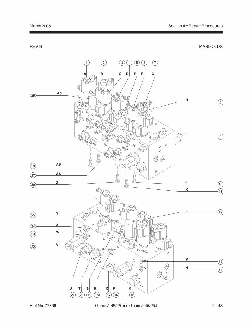
Part No. 77809 Genie Z-45/25 and Genie Z-45/25J 4 - 43
March 2005 Section 4 • Repair Procedures
REV B
A
AC
B C D E F G
H
I
J
K
L
M
N
OPQRSTU
V
W
X
Y
Z
AA
AB
1 2 3 4 5 6 7
2021 19 18 17 16 15
8
9
12
10
11
13
14
22
24
25
23
27
26
28
29
MANIFOLDS

4 - 44 Genie Z-45/25 and Genie Z-45/25J Part No. 77809
March 2005Section 4 • Repair Procedures
REV BMANIFOLDS
8-4Valve Adjustments -Function Manifold(after serial number 22049)
How to Adjust the SystemRelief Valve
Perform this procedure with theboom in the stowed position.
1 Connect a 0 to 5000 psi / 0 to 350 bar pressuregauge to the TEST1 port on the function manifold.
2 Start the engine from the ground controls.
3 Hold the function enable switch to the high rpmposition and activate and hold the primary boomretract switch with the boom fully retracted.
4 Observe the pressure reading on the pressuregauge. Refer to Section 2, Specifications.
5 Turn the engine off. Use a wrench to hold therelief valve and remove the cap (item P).
6 Adjust the internal hex socket. Turn it clockwiseto increase the pressure or counterclockwise todecrease the pressure. Install the relief valvecap.
Tip-over hazard. Do not adjustthe relief valve higher thanspecified.
7 Repeat steps 2 through 5 and recheck reliefvalve pressure.
8 Remove the pressure gauge.
How to Adjust the SecondaryBoom Down Relief Valve
Perform this procedure with theboom in the stowed position.
1 Connect a 0 to 5000 psi / 0 to 350 bar pressuregauge to the TEST1 port on the function manifold.
2 Start the engine from the ground controls.
3 Hold the function enable switch to the high rpmposition and activate and hold the secondaryboom down switch with the secondary boomfully lowered.
4 Observe the pressure reading on the pressuregauge. Refer to Section 2, Specifications.
5 Turn the engine off. Use a wrench to hold therelief valve and remove the cap (item AC).
6 Adjust the internal hex socket. Turn it clockwiseto increase the pressure or counterclockwise todecrease the pressure. Install the relief valvecap.
Tip-over hazard. Do not adjustthe relief valve higher thanspecified.
7 Repeat steps 2 through 5 and recheck reliefvalve pressure.
8 Remove the pressure gauge.

Part No. 77809 Genie Z-45/25 and Genie Z-45/25J 4 - 45
March 2005 Section 4 • Repair Procedures
REV B
8-5Jib Boom / Platform Rotate Manifold Components(before serial number 22050)
Index SchematicNo. Description Item Function Torque
1 Solenoid valve, 2 position 3 way ..... AU ........ Platform rotate/jib boom select ........... 8-10 ft-lbs / 11-14 Nm2 Solenoid valve, 2 position 3 way ..... AV ......... Platform rotate/jib boom select ........... 8-10 ft-lbs / 11-14 Nm
AU AV
1 2
MANIFOLDS

4 - 46 Genie Z-45/25 and Genie Z-45/25J Part No. 77809
March 2005Section 4 • Repair Procedures
REV B
8-6Jib Boom / Platform Rotate Manifold Components(after serial number 22049)
Index SchematicNo. Description Item Function Torque
1 Solenoid valve, 2 position 3 way ..... AD ........ Platform rotate/jib boom select ........... 8-10 ft-lbs / 11-14 Nm
MANIFOLDS
AD
1

Part No. 77809 Genie Z-45/25 and Genie Z-45/25J 4 - 47
March 2005 Section 4 • Repair Procedures
REV B
8-7Turntable Rotation Manifold Components
The turntable rotation manifold is mounted to the turntable rotation motor located in the boom storagecompartment.
Index SchematicNo. Description Item Function Torque
1 Shuttle valve, 2 position 3 way ....... LL ........... Turntable rotation brake release ..... 10-13 ft-lbs / 14-18 Nm
2 Counterbalance valve .................... MM .......... Turntable rotate right ....................... 35-40 ft-lbs / 47-54 Nm
3 Counterbalance valve .................... NN ........... Turntable rotate left .......................... 35-40 ft-lbs / 47-54 Nm
MANIFOLDS
321
LL
MM
NN

4 - 48 Genie Z-45/25 and Genie Z-45/25J Part No. 77809
March 2005Section 4 • Repair Procedures
REV B
8-8Directional Valve Manifold Components
The directional valve manifold is mounted inside the drive chassis at the non-steer end.
IndexNo. Description Function Torque
1 Cap ................................................................... Breather ............................................ 20-25 ft-lbs / 27-33 Nm
2 Spool valve ...................................................... Directional control
MANIFOLDS
1
2

Part No. 77809 Genie Z-45/25 and Genie Z-45/25J 4 - 49
March 2005 Section 4 • Repair Procedures
REV B
How to Set Up the DirectionalValve Linkage
Adjustment of the directional valvelinkage is only necessary when thelinkage or valve has beenreplaced.
1 Lower the boom to the stowed position.
2 Use a "bubble type" level to be sure the floor iscompletely level.
Tip-over hazard. Failure to performthis procedure on a level floorcould compromise the stability ofthe machine resulting in themachine tipping over.
3 Check the tire pressure in all four tires and addair if needed to meet specification.
4 Remove the drive chassis cover and the non-steer axle covers.
5 Place a "bubble type" level across the drivechassis non-steer end. Check to be sure thedrive chassis is completely level.
6 To level the drive chassis, start the engine andloosen the lock nuts on both sides of theurethane cushions.
7 Push up or pull down on the threaded rod untilthe machine is completely level.
MANIFOLDS
8 Verify that the ground and drive chassis arecompletely level.
9 Tighten the nuts on both sides of the urethanecushions until they are snug. Tighten thelocknuts.
10 Check to be sure the drive chassis iscompletely level.
11 Measure the distance between the drive chassisand the non-steer axle on both sides (from theinside of the drive chassis).
If the distance is not equal and theadjustment to the linkage wascompleted with the ground anddrive chassis level, repeat steps 6through 10 OR consult GenieIndustries Service Department.

4 - 50 Genie Z-45/25 and Genie Z-45/25J Part No. 77809
March 2005Section 4 • Repair Procedures
REV B
8-9Drive Manifold Components, 2WD
The drive manifold is mounted inside the drive chassis at the non-steer end.
Index SchematicNo. Description Item Function Torque
1 Solenoid valve, 2 position 3 way ...... OO ........ Braking .............................................10-12 ft-lbs / 14-16 Nm
2 Relief valve, 250 psi / 17.2 bar ......... PP ......... Charge pressure circuit ....................10-12 ft-lbs / 14-16 Nm
3 Flow divider/combiner valve ............. QQ ........ Controls flow to drive motorsin forward and reverse .....................25-30 ft-lbs / 34-41 Nm
4 Orifice, 0.070 in / 1.78 mm ................ RR ........ Drive circuit
5 Check valve ....................................... SS ......... Drive circuit .......................................25-30 ft-lbs / 34-41 Nm
6 Check valve ....................................... TT ......... Drive circuit .......................................25-30 ft-lbs / 34-41 Nm
7 Shuttle valve, 3 position 3 way ......... UU ........ Charge pressure circuit thatdirects hot oil out of low pressureside of drive pump and allowslow pressure flow path forbrake release and 2-speedmotor shift .........................................15-18 ft-lbs / 20-24 Nm
8 Diagnostic fitting ................................ VV ......... Testing
9 Orifice, 0.030 in / 0.76 mm ................ WW ....... Brake circuit
10 Solenoid valve, 2 position 3 way ...... XX ......... 2-speed motor shift ...........................10-12 ft-lbs / 14-16 Nm
MANIFOLDS

Part No. 77809 Genie Z-45/25 and Genie Z-45/25J 4 - 51
March 2005 Section 4 • Repair Procedures
REV B MANIFOLDS
78
1 2 3
9
10
5
4
6
OO
PP
RR
SS
TT
UU
VV
WW
XX
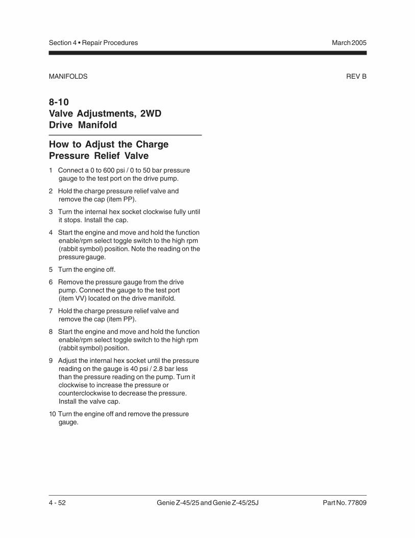
4 - 52 Genie Z-45/25 and Genie Z-45/25J Part No. 77809
March 2005Section 4 • Repair Procedures
REV B
8-10Valve Adjustments, 2WDDrive Manifold
How to Adjust the ChargePressure Relief Valve1 Connect a 0 to 600 psi / 0 to 50 bar pressure
gauge to the test port on the drive pump.
2 Hold the charge pressure relief valve andremove the cap (item PP).
3 Turn the internal hex socket clockwise fully untilit stops. Install the cap.
4 Start the engine and move and hold the functionenable/rpm select toggle switch to the high rpm(rabbit symbol) position. Note the reading on thepressure gauge.
5 Turn the engine off.
6 Remove the pressure gauge from the drivepump. Connect the gauge to the test port(item VV) located on the drive manifold.
7 Hold the charge pressure relief valve andremove the cap (item PP).
8 Start the engine and move and hold the functionenable/rpm select toggle switch to the high rpm(rabbit symbol) position.
9 Adjust the internal hex socket until the pressurereading on the gauge is 40 psi / 2.8 bar lessthan the pressure reading on the pump. Turn itclockwise to increase the pressure orcounterclockwise to decrease the pressure.Install the valve cap.
10 Turn the engine off and remove the pressuregauge.
MANIFOLDS

Part No. 77809 Genie Z-45/25 and Genie Z-45/25J 4 - 53
March 2005 Section 4 • Repair Procedures
REV B MANIFOLDS
This page intentionally left blank.

4 - 54 Genie Z-45/25 and Genie Z-45/25J Part No. 77809
March 2005Section 4 • Repair Procedures
REV B
8-11Drive Manifold Components, 4WD
The drive manifold is mounted inside the drive chassis at the non-steer end.
Index SchematicNo. Description Item Function Torque
1 Flow divider/combiner valve .............. AB ......... Controls flow to non-steer enddrive motors in forwardand reverse ....................................... 25-30 ft-lbs / 34-41 Nm
2 Bi-directional flow control valve,2 gpm / 7.6 L/min ............................... AC ........ Non-steer end drive motor circuit ..... 25-30 ft-lbs / 34-41 Nm
3 Bi-directional flow control valve,1 gpm / 3.8 L/min ............................... AD ........ Steer end drive motor circuit ............ 25-30 ft-lbs / 34-41 Nm
4 Directional control valve ................... AE ......... 2 speed motor shift circuit/High speed bypass ........................... 10-12 ft-lbs / 14-16 Nm
5 Diagnostic fitting ................................ AF ......... Testing
6 Shuttle valve, 3 position 3 way ......... AG ........ Charge pressure circuit thatdirects hot oil out of low pressureside of drive pump and allowslow pressure flow path forbrake release and 2-speedmotor shift ......................................... 15-18 ft-lbs / 20-24 Nm
7 Relief valve, 250 psi / 17.2 bar ......... AH ........ Charge pressure circuit .................... 10-12 ft-lbs / 14-16 Nm
8 Solenoid valve, 2 position 3 way ...... AI .......... 2-speed motor shift ........................... 10-12 ft-lbs / 14-16 Nm
9 Orifice, 0.030 inch / 0.76 mm ............ AJ ......... Brake circuit
10 Solenoid valve, 2 position 3 way ...... AK ......... Braking ............................................. 10-12 ft-lbs / 14-16 Nm
11 Check valve ....................................... AL ......... 2 speed motor shift circuit ................. 10-12 ft-lbs / 14-16 Nm
12 Orifice, 0.025 inch / 0.64 mm ............ AM ........ 2 speed motor shift circuit
13 Flow divider/combiner valve ............. AN ........ Controls flow to flowdivider/combiner valves 1 and 17 .... 25-30 ft-lbs / 34-41 Nm
14 Check valve ....................................... AO ........ Steer end drive motor circuit ............ 10-12 ft-lbs / 14-16 Nm
15 Orifice, 0.052 in / 1.32 mm ................ AP ......... Drive circuit
16 Check valve ....................................... AQ ........ Steer end drive motor circuit ............ 10-12 ft-lbs / 14-16 Nm
17 Flow divider/combiner valve ............. AR ........ Controls flow to steer enddrive motors in forwardand reverse ....................................... 25-30 ft-lbs / 34-41 Nm
18 Check valve ....................................... AS ......... Non-steer end drive motor circuit ..... 10-12 ft-lbs / 14-16 Nm
19 Check valve ....................................... AT ......... Non-steer end drive motor circuit ..... 10-12 ft-lbs / 14-16 Nm
MANIFOLDS

Part No. 77809 Genie Z-45/25 and Genie Z-45/25J 4 - 55
March 2005 Section 4 • Repair Procedures
REV B
1 32 4 5 6 7 8 9
17
18
19
10
11
12
13
14
15
16
AB
AC
AD
AE
AF
AG
AH
AI
AJ
AK
AL
AMAN
AO
AP
AQ
AR
AS
AT

4 - 56 Genie Z-45/25 and Genie Z-45/25J Part No. 77809
March 2005Section 4 • Repair Procedures
REV BMANIFOLDS
8-12Valve Adjustments, 4WDDrive Manifold
How to Adjust the ChargePressure Relief Valve1 Connect a 0 to 600 psi / 0 to 50 bar pressure
gauge to the test port on the drive pump.
2 Hold the charge pressure relief valve andremove the cap (item AH).
3 Turn the internal hex socket clockwise fully untilit stops. Install the cap.
4 Start the engine and move and hold the functionenable/rpm select toggle switch to the high rpm(rabbit symbol) position. Note the reading on thepressure gauge.
5 Turn the engine off.
6 Remove the pressure gauge from the drivepump. Connect the gauge to the test port(item AF) located on the drive manifold.
7 Hold the charge pressure relief valve andremove the cap (item AH).
8 Start the engine and move and hold the functionenable/rpm select toggle switch to the high rpm(rabbit symbol) position.
9 Adjust the internal hex socket until the pressurereading on the gauge is 40 psi / 2.8 bar lessthan the pressure reading on the pump. Turn itclockwise to increase the pressure orcounterclockwise to decrease the pressure.Install the valve cap.
10 Turn the engine off and remove the pressuregauge.

Part No. 77809 Genie Z-45/25 and Genie Z-45/25J 4 - 57
March 2005 Section 4 • Repair Procedures
REV A
3 Remove the safety pin from the engine pivotplate latch.
The engine pivot plate latch islocated under the engine turntablepivot plate at the counterweightend of the machine.
4 Open the engine pivot plate latch and swing theengine pivot plate out and away from themachine to access the turntable rotation motor.
5 Tag, disconnect and plug the hydraulic hosesfrom the turntable rotation motor manifold. Capthe fittings on the manifold.
Bodily injury hazard. Sprayinghydraulic oil can penetrate andburn skin. Loosen hydraulicconnections very slowly to allowthe oil pressure to dissipategradually. Do not allow oil to squirtor spray.
6 Attach a lifting strap from and overhead crane orother suitable lifting device to the turntablerotator assembly.
7 Remove the turntable rotation assemblymounting fasteners.
8 Carefully remove the turntable rotation assemblyfrom the machine.
Crushing hazard. The turntablerotation assembly could becomeunbalanced and fall when removedfrom the machine if not properlysupported by the overhead crane.
Turntable Rotation Components
9-1Turntable Rotation Assembly
How to Remove the TurntableRotation Assembly
When removing a hose assemblyor fitting, the O-ring on the fittingand/or hose end must be replacedand then torqued to specificationduring installation.Refer to Section 2, Hydraulic Hoseand Fitting Torque Specifications.
1 Raise the secondary boom until the upper pivotis above the turntable covers. Turn the machineoff.
2 Secure the turntable from rotating with theturntable rotation lock pin.
Crushing hazard. The machinecould tip over when the turntablerotation assembly is removed if theturntable rotation lock is not in thelocked position.
Unlocked position
Locked position

4 - 58 Genie Z-45/25 and Genie Z-45/25J Part No. 77809
March 2005Section 4 • Repair Procedures
REV B
How to Install the Hub andBearings, 2WD Models
When replacing a wheel bearing,both the inner and outer bearingsincluding the pressed-in racesmust be replaced.
1 Be sure that both bearings are packedwith clean, fresh grease.
2 Place the large inner bearing into the rearof the hub.
3 Press the bearing seal evenly into the hubuntil it is flush.
4 Slide the hub onto the yoke spindle.
Component damage. Do notapply excessive force or damageto the lip of the seal may occur.
5 Place the outer bearing into the hub.
6 Install the washer and castle nut.
7 Tighten the castle nut to 35 ft-lbs / 47 Nm toseat the bearing.
8 Fully loosen the castle nut, then re-tighten to8 ft-lbs / 11 Nm.
9 Install a new cotter pin. Bend the cotter pinto secure the castle nut.
Always use a new cotter pin wheninstalling a castle nut.
10 Install the dust cap, then the tire and wheelassembly. Torque the wheel lug nuts tospecification. Refer to Section 2, Specifications.
Axle Components
10-1Hub and Bearings, 2WD Models
How to Remove theHub and Bearings, 2WD Models1 Loosen the wheel lug nuts. Do not remove them.
2 Block the non-steering wheels and place a liftingjack of ample capacity under the steer axle.
3 Raise the machine 6 inches / 15 cm and placeblocks under the chassis for support.
Crushing hazard. The machinemay fall if not properly supported.
4 Remove the lug nuts. Remove the tire and wheelassembly.
5 Remove the dust cap, cotter pin andcastle nut.
Always use a new cotter pin wheninstalling a castle nut.
6 Pull the hub off the spindle. The washer andouter bearing should fall loose from the hub.
7 Place the hub on a flat surface and gently prythe bearing seal out of the hub.
8 Remove the rear bearing.

Part No. 77809 Genie Z-45/25 and Genie Z-45/25J 4 - 59
March 2005 Section 4 • Repair Procedures
REV A
10-2Oscillating AxleLock-out Cylinders
The oscillating axle cylinders extend and retractbetween the drive chassis and the oscillating axle.The cylinders are equipped with counterbalancevalves to prevent movement in the event of ahydraulic line failure. The valves are not adjustable.
How to Remove an OscillatingAxle Cylinder
Perform this procedure on a firm,level surface with the boom inthe stowed position.
When removing a hose assemblyor fitting, the O-ring on the fittingand/or hose end must be replacedand then torqued to specificationduring installation.Refer to Section 2, Hydraulic Hoseand Fitting Torque Specifications.
1 Tag, disconnect and plug the oscillating axlecylinder hydraulic hoses. Cap the fittings on theoscillate cylinder.
Bodily injury hazard. Sprayinghydraulic oil can penetrate andburn skin. Loosen hydraulicconnections very slowly to allowthe oil pressure to dissipategradually. Do not allow oil to squirtor spray.
2 Remove the pin retaining fasteners from therod-end pivot pin. Use a soft metal drift toremove the pin.
3 Attach a lifting strap from an overhead crane tothe barrel end of the oscillating cylinder.
4 Remove the pin retaining fasteners from thebarrel-end pivot pin. Use a soft metal drift toremove the pin.
Crushing hazard. The oscillatecylinder may become unbalancedand fall when removed from themachine if not properly attached tothe overhead crane.
5 Remove the oscillate cylinder from the machine.
AXLE COMPONENTS

4 - 60 Genie Z-45/25 and Genie Z-45/25J Part No. 77809
March 2005Section 4 • Repair Procedures
REV A
This page intentionally left blank.

Part No. 77809 Genie Z-45/25 and Genie Z-45/25J 5 - 1
March 2005 Section 5 • Fault Codes
Before Troubleshooting:
Read, understand and obey the safety rules andoperating instructions printed in theGenie Z-45/25 and Genie Z-45/25J Operator’sManual on your machine.
Be sure that all necessary tools and testequipment are available and ready for use.
Read each appropiate fault code thoroughly.Attempting shortcuts may produce hazardousconditions.
Be aware of the following hazards and followgenerally accepted safe workshop practices.
Crushing hazard. When testingor replacing any hydrauliccomponent, always supportthe structure and secure itfrom movement.
Electrocution hazard. Contactwith electrically charged circuitscould result in death or seriousinjury. Remove all rings, watchesand other jewelry.
Bodily injury hazard. Sprayinghydraulic oil can penetrate andburn skin. Loosen hydraulicconnections very slowly to allowthe oil pressure to dissipategradually. Do not allow oil tosquirt or spray.
Perform all troubleshooting on afirm level surface.
Two persons will be required tosafely perform sometroubleshooting procedures.
Fault Codes
Observe and Obey:
Troubleshooting and repair procedures shall becompleted by a person trained and qualified onthe repair of this machine.
Immediately tag and remove from service adamaged or malfunctioning machine.
Repair any machine damage or malfunctionbefore operating the machine.
Unless otherwise specified, perform eachrepair procedure with the machine in thefollowing configuration:
· Machine parked on a firm, level surface
· Boom in stowed position
· Turntable rotated with the boom between the non-steering wheels
· Turntable secured with the turntable rotation lock
· Key switch in the off position with the key removed
· Wheels chocked
· All external AC power supply disconnectedfrom the machine

5 - 2 Genie Z-45/25 and Genie Z-45/25J Part No. 77809
March 2005Section 5 • Fault Codes
REV BFAULT CODES
Fault Codes - Control System
How to Retrieve Control SystemFault Codes
At least one fault code is presentwhen the alarm at the platformcontrols produces two short beepsevery 30 seconds for 10 minutes.
Perform this procedure with theengine off, the key switch turned toplatform controls and the redEmergency Stop button pulled outto the on position at both theground and platform controls.
1 Open the platform control box lid.
Electrocution hazard. Contactwith electrically charged circuitscould result in death or seriousinjury. Remove all rings, watchesand other jewelry.
2 Locate the red and yellow fault LEDs on theALC-500 circuit board inside the platform controlbox. Do not touch the circuit board.
Component damage hazard.Electrostatic discharge (ESD) candamage printed circuit boardcomponents. If the circuit boarddoes need to be handled, maintainfirm contact with a metal part ofthe machine that is grounded at alltimes when handling the printedcircuit board OR use a groundedwrist strap.
3 Determine the error source: The red LEDindicates the error source and will flash twoseparate codes. The first code will indicate thefirst digit of the two digit code, flashing once persecond. It will then pause for 1.5 seconds andflash the second digit once per 0.5 second.
When the red LED is flashing thecode, the yellow LED will be onsolid.
4 Determine the error type: The yellow LEDindidates the error type and will flash twoseparate codes. The first code will indicate thefirst digit of the two digit code, flashing once persecond. It will then pause for 1.5 seconds andflash the second digit once per 0.5 second.
When the yellow LED is flashingthe code, the red LED will be onsolid.
5 Use the fault code table on the following pagesto aid in troubleshooting the machine bypinpointing the area or component affected.

Part No. 77809 Genie Z-45/25 and Genie Z-45/25J 5 - 3
March 2005 Section 5 • Fault Codes
REV B
Error Source Error TypeID Name ID Name
Condition Solution11121516
Value at 5VValue too highValue too lowValue at 0V
Limited speed anddirection frozen atzero and neutral.Alarm soundsindicating fault.
Power upcontroller withproblem corrected.
17 Not calibratedJoystick speed anddirection frozen atzero and neutral.
Calibrate joystick.
21 Boom 1 Joystick(primary boom up/down)
18 Just calibrated Initiate 1-second beepof alarm.
Self-clearing.(transient)
22 Boom 1 directionalvalves
21 Fault
Limited speed anddirection frozen atzero and neutral.Alarm soundsindicating fault.
Power upcontroller withproblem corrected.
1215
Value too highValue too low
Limited speed anddirection frozen atzero and neutral.Alarm soundsindicating fault.
Power upcontroller withproblem corrected.
17 Not calibrated Calibrate valvethresholds.
23 Boom 1 flowcontrol valve
18 Just calibrated
Normal functionexcept threshold forone or both directionsis zero.
Self-clearing.(transient)
11121516
Value at 5VValue too highValue too lowValue at 0V
Limited speed anddirection frozen atzero and neutral.Alarm soundsindicating fault.
Power upcontroller withproblem corrected.
17 Not calibratedJoystick speed anddirection frozen atzero and neutral.
Calibrate joystick.
31 Boom 2 Joystick(secondary boomup/down orprimary boomextend/retract)
18 Just calibrated Initiate 1 second beepof alarm.
Self-clearing.(transient)
32 Boom 2 directionalvalves
21 Fault
Limited speed anddirection frozen atzero and neutral.Alarm soundsindicating fault.
Power upcontroller withproblem corrected.
Continued on next page
FAULT CODES

5 - 4 Genie Z-45/25 and Genie Z-45/25J Part No. 77809
March 2005Section 5 • Fault Codes
REV B
Error Source Error TypeID Name ID Name
Condition Solution
1215
Value too highValue too low
Limited speed anddirection frozen atzero and neutral.Alarm soundsindicating fault.
Power upcontroller withproblem corrected.
17 Not calibratedCalibrate valvethresholds.
33 Boom 2 flowcontrol valve
18 Just calibrated
Normal functionexcept threshold forone or both directionsis zero.
Self-clearing.(transient)
11121516
Value at 5VValue too highValue too lowValue at 0V
Limited speed anddirection frozen atzero and neutral.Alarm soundsindicating fault.
Power upcontroller withproblem corrected.
17 Not calibratedJoystick speed anddirection frozen atzero and neutral.
Calibrate joystick.
41 Turntable rotatejoystick
18 Just calibrated Initiate 1-second beepof alarm.
Self-clearing.(transient)
42 Turntable rotatedirectional valves
21 Fault
Limited speed anddirection frozen atzero and neutral.Alarm soundsindicating fault.
Power upcontroller withproblem corrected.
1215
Value too highValue too low
Limited speed anddirection frozen atzero and neutral.Alarm soundsindicating fault.
Power upcontroller withproblem corrected.
17 Not calibrated Calibrate valvethresholds.
43 Turntable rotateflow control valve
18 Just calibrated
Normal functionexcept threshold forone or both directionsis zero.
Self-clearing.(transient)
44 Drive enableoverride switches 21 Fault
Enable overridedirection is frozen atneutral.
Power upcontroller withproblem corrected.
FAULT CODES

Part No. 77809 Genie Z-45/25 and Genie Z-45/25J 5 - 5
March 2005 Section 5 • Fault Codes
REV B
Error Source Error TypeID Name ID Name
Condition Solution11121516
Value at 5VValue too highValue too lowValue at 0V
Limited speed anddirection frozen atzero and neutral.Alarm soundsindicating fault.
Power upcontroller withproblem corrected.
17 Not calibratedJoystick speed anddirection frozen atzero and neutral.
Calibrate joystick
51 Drive joystick
18 Just calibrated Initiate 1-second beepof alarm.
Self-clearing.(transient)
1215
Value too highValue too low
Limited speed anddirection frozen atzero and neutral.Alarm soundsindicating fault.
Power upcontroller withproblem corrected.
17 Not calibrated Calibrate valvethresholds
53 Drive flow valve(EDC)
18 Just calibrated
Normal functionexcept threshold forone or both directionsis zero.
Self-clearing.(transient)
54 Drive brake valve
21 Fault
Limited speed anddirection frozen atzero and neutral.Alarm soundsindicating fault.
Power upcontroller withproblem corrected.
55 High speed drivemotor Valve 21 Fault
Motor speed frozen inthe low state. Alarmsounds indicatingfault.
Power upcontroller withproblem corrected.
11121516
Value at 5VValue too highValue too lowValue at 0V
Limited speed anddirection frozen atzero and neutral.Alarm soundsindicating fault.
Power upcontroller withproblem corrected.
17 Not calibratedJoystick speed anddirection frozen atzero and neutral.
Calibrate Joystick
61 Steer joystick
18 Just calibrated Initiate 1-second beepof alarm.
Self-clearing.(transient)
62 Steer directionalvalves
21 Fault
Limited speed anddirection frozen atzero and neutral.Alarm soundsindicating fault.
Power upcontroller withproblem corrected.
FAULT CODES

5 - 6 Genie Z-45/25 and Genie Z-45/25J Part No. 77809
March 2005Section 5 • Fault Codes
REV B
Fault codes - Ford Models
The ECM constantly monitors the engine by theuse of sensors on the engine. The ECM also usessignals from the sensors to initiate sequential fuelinjection and make constant and instantaneouschanges to ignition timing, fuel delivery and throttleposition to maintain the engine's running conditionat its highest efficiency while at the same timekeeping exhaust emissions to a minimum. When asensor fails or returns signals that are outside ofset parameters, the ECM will store a fault code inmemory that relates to the appropriate sensor andwill turn on the Check Engine Light.
Refer to Repair Procedure 6-4, How to RetrieveEngine Fault Codes. Use the Fault Code Chart onthe following pages to aid in identifying the fault.
FAULT CODES

Part No. 77809 Genie Z-45/25 and Genie Z-45/25J 5 - 7
March 2005 Section 5 • Fault Codes
REV B FAULT CODES
Code Problem Cause Solution
111Closed Loop Multiplier High (LPG)
Heated Oxygen Sensor wiring and/or connections open or shorted OR sensor is faulty OR there are vacuum leaks or exhaust leaks.
Repair wiring and/or connections OR replace sensor OR repair vacuum and exhaust leaks.
112HO2S Open/Inactive (Bank 1)
Heated Oxygen Sensor wiring and/or connections open or shorted OR sensor is faulty.
Repair wiring and/or connections OR replace sensor.
113HO2S Open/Inactive (Bank 2)
Heated Oxygen Sensor wiring and/or connections open or shorted OR sensor is faulty.
Repair wiring and/or connections OR replace sensor.
121Closed Loop Multiplier High (Gasoline)
Heated Oxygen Sensor wiring and/or connections open or shorted OR sensor is faulty OR there are vacuum leaks or exhaust leaks OR fuel pressure is low OR the fuel injectors need cleaning or replacing.
Repair wiring and/or connections OR replace sensor OR repair any vacuum and exhaust leaks OR test the fuel pressure OR clean or replace the fuel injectors.
122Closed Loop Multiplier Low (Gasoline)
MAP, IAT or ECT sensors not in correct position OR wiring and/or connections for sensors open or shorted OR sensor is faulty OR one or more fuel injectors are stuck open OR there is electro-magnetic interference from a faulty crankshaft and/or camshaft po
Adjust or replace sensors OR clean or repair fuel injectors.
124Closed Loop Multiplier Low (LPG)
Heated Oxygen Sensor wiring and/or connections open or shorted OR sensor is faulty OR fuel quality is poor OR fuel system components may be faulty.
Repair wiring and/or connections OR replace sensor OR replace fuel OR test and repair the fuel system components.
Continued on next page

5 - 8 Genie Z-45/25 and Genie Z-45/25J Part No. 77809
March 2005Section 5 • Fault Codes
REV BFAULT CODES
Code Problem Cause Solution
141Adaptive Lean Fault - High Limit (Gasoline)
Heated Oxygen Sensor wiring and/or connections open or shorted OR sensor is faulty OR there are vacuum or exhaust leaks OR one or more fuel injectors faulty or stuck closed OR fuel quality is poor OR fuel pressure is too low.
Repair heated oxygen sensor wiring and/or connections OR replace sensor OR repair vacuum and exhaust leaks OR test the fuel pressure OR clean or replace the fuel injectors.
142Adaptive Rich Fault - Low Limit (Gasoline)
MAP, IAT or ECT sensors not in correct position OR wiring and/or connections for sensors open or shorted OR sensor is faulty OR one or more fuel injectors are stuck closed OR there is electro-magnetic interference from a faulty crankshaft and/or camshaft
Adjust or replace sensors OR clean or repair fuel injectors.
143Adaptive Learn High (LPG)
Heated Oxygen Sensor wiring and/or connections open or shorted OR sensor is faulty OR there are vacuum leaks or exhaust leaks OR fuel quality is poor OR fuel system components may be faulty.
Repair wiring and/or connections OR replace sensor OR repair any vacuum and exhaust leaks OR replace fuel OR test and repair the fuel system components.
144Adaptive Learn Low (LPG)
Engine wire harness may have an intermittent short to 5V DC or 12V DC OR fuel system components may be faulty.
Repair short in engine wire harness OR test and repair the fuel system components.
161 System Voltage Low
Battery is faulty OR alternator is not charging OR battery supply wiring to ECM is open or shorted.
Replace battery OR repair alternator OR repair battery supply wiring to ECM.
162 System Voltage HighAlternator is overcharging the battery when engine RPM is greater than 1500 rpm.
Repair or replace the alternator.

Part No. 77809 Genie Z-45/25 and Genie Z-45/25J 5 - 9
March 2005 Section 5 • Fault Codes
REV B FAULT CODES
Code Problem Cause Solution
211 IAT High Voltage
IAT sensor wiring and/or connections are open or shorted OR sensor is faulty OR engine intake air temperature is too cold.
Repair wiring and/or connections OR replace sensor OR direct warmer air into air intake.
212 IAT Low Voltage
IAT sensor wiring and/or connections are open or shorted OR sensor is faulty OR engine intake air temperature is too hot.
Repair wiring and/or connections OR replace sensor OR direct cooler air into air intake.
213IAT Higher Than Expected (1)
Air intake temperature is greater than 200° F with the engine greater than 1000 rpm OR air intake system as leaks OR IAT sensor is faulty.
Check air intake system for damage and proper routing of air intake components OR replace the IAT sensor.
214IAT Higher Than Expected (2)
Air intake temperature is greater than 210° F with the engine greater than 1000 rpm OR air intake system as leaks OR IAT sensor is faulty.
Check air intake system for damage and proper routing of air intake components OR replace the IAT sensor.
215 Oil Pressure Low
Faulty oil pressure sensor OR sensor wiring and/or connections open or shorted OR engine oil level too low.
Replace oil pressure sensor OR repair sensor wiring and/or connections OR fill engine oil level to specification.
221CHT/ECT High Voltage
Engine cooling system is malfunctioning OR sensor wires and/or connections open or shorted OR sensor is faulty.
Repair engine cooling system problems OR repair open or shorted wiring to sensor OR replace sensor.
222CHT/ECT Low Voltage
Engine cooling system is malfunctioning and overheating the engine OR sensor wires and/or connections open or shorted OR sensor is faulty OR coolant level is low.
Repair engine cooling system problems OR repair open or shorted wiring to sensor OR replace sensor OR fill engine coolant level to specification.
Continued on next page

5 - 10 Genie Z-45/25 and Genie Z-45/25J Part No. 77809
March 2005Section 5 • Fault Codes
REV B
Code Problem Cause Solution
223CHT Higher Than Expected (1)
Coolant temperature at the cylinder head is 240° F. Engine cooling system is malfunctioning and overheating the engine OR sensor wires and/or connections open or shorted OR sensor is faulty OR coolant level is low.
Repair engine cooling system problems OR repair open or shorted wiring to sensor OR replace sensor OR fill engine coolant level to specification.
224CHT Higher Than Expected (2)
Coolant temperature at the cylinder head is 250° F. Engine cooling system is malfunctioning and overheating the engine OR sensor wires and/or connections open or shorted OR sensor is faulty OR coolant level is low.
Repair engine cooling system problems OR repair open or shorted wiring to sensor OR replace sensor OR fill engine coolant level to specification.
231 MAP High PressureOpen or shorted wiring and/or connections to MAP sensor OR sensor is faulty.
Repair wiring and/or connections to sensor OR replace MAP sensor.
232 MAP Low VoltageOpen or shorted wiring and/or connections to MAP sensor OR sensor is faulty.
Repair wiring and/or connections to sensor OR replace MAP sensor.
234 BP High PressureMAP sensor is faulty OR ECM is faulty.
Replace MAP sensor OR replace the ECM.
235 BP Low PressureMAP sensor is faulty OR ECM is faulty.
Replace MAP sensor OR replace the ECM.
242 Crank Sync Noise
Crankshaft position sensor wiring and/or connections open or shorted OR there is a poor system ground connection OR sensor is faulty.
Be sure system ground connections are in place and secure OR repair wiring and/or connections to sensor OR replace sensor.
243Never Crank Synced At Start
Crankshaft position sensor wiring and/or connections open or shorted OR there is a poor system ground connection OR sensor is faulty.
Be sure system ground connections are in place and secure OR repair wiring and/or connections to sensor OR replace sensor.
FAULT CODES

Part No. 77809 Genie Z-45/25 and Genie Z-45/25J 5 - 11
March 2005 Section 5 • Fault Codes
REV B
Code Problem Cause Solution
Continued on next page
FAULT CODES
244 Camshaft Sensor Loss
Camshaft position sensor wiring and/or connections open or shorted OR there is a poor system ground connection OR sensor is faulty.
Be sure system ground connections are in place and secure OR repair wiring and/or connections to sensor OR replace sensor.
245 Camshaft Sensor Noise
Camshaft position sensor wiring and/or connections open or shorted OR there is a poor system ground connection OR sensor is faulty.
Be sure system ground connections are in place and secure OR repair wiring and/or connections to sensor OR replace sensor.
253 Knock Sensor OpenKnock sensor wiring and/or connections open or shorted OR sensor is faulty.
Repair wiring and/or connections to knock sensor OR replace knock sensor.
254Excessive Knock Signal
Knock sensor wiring and/or connections open or shorted OR there is excessive engine vibration OR sensor is faulty.
Check for excessive engine vibration OR repair wiring and/or connections to knock sensor OR replace knock sensor.
311 Injector Driver #1 Open
Open wiring and/or connections to fuel injector #1 OR fuel injector #1 is faulty OR ECM is faulty.
Repair wiring and/or connections to fuel injector #1 OR replace fuel injector #1 OR replace the ECM.
312 Injector Driver #1 Shorted
Wiring and/or connections to fuel injector #1 shorted OR fuel injector #1 is faulty OR ECM is faulty.
Repair wiring and/or connections to fuel injector #1 OR replace fuel injector #1 OR replace the ECM.
313 Injector Driver #2 Open
Open wiring and/or connections to fuel injector #2 OR fuel injector #2 is faulty OR ECM is faulty.
Repair wiring and/or connections to fuel injector #2 OR replace fuel injector #2 OR replace the ECM.

5 - 12 Genie Z-45/25 and Genie Z-45/25J Part No. 77809
March 2005Section 5 • Fault Codes
REV B
Code Problem Cause Solution
FAULT CODES
314 Injector Driver #2 Shorted
Wiring and/or connections to fuel injector #2 shorted OR fuel injector #2 is faulty OR ECM is faulty.
Repair wiring and/or connections to fuel injector #2 OR replace fuel injector #2 OR replace the ECM.
315 Injector Driver #3 Open
Open wiring and/or connections to fuel injector #3 OR fuel injector #3 is faulty OR ECM is faulty.
Repair wiring and/or connections to fuel injector #3 OR replace fuel injector #3 OR replace the ECM.
316 Injector Driver #3 Shorted
Wiring and/or connections to fuel injector #3 shorted OR fuel injector #3 is faulty OR ECM is faulty.
Repair wiring and/or connections to fuel injector #3 OR replace fuel injector #3 OR replace the ECM.
321 Injector Driver #4 Open
Open wiring and/or connections to fuel injector #4 OR fuel injector #4 is faulty OR ECM is faulty.
Repair wiring and/or connections to fuel injector #4 OR replace fuel injector #4 OR replace the ECM.
322 Injector Driver #4 Shorted
Wiring and/or connections to fuel injector #4 shorted OR fuel injector #4 is faulty OR ECM is faulty.
Repair wiring and/or connections to fuel injector #4 OR replace fuel injector #4 OR replace the ECM.
351Fuel Pump Loop Open or High Side Short To Ground
Open wiring and/or connections to fuel pump OR fuel pump power shorted to ground OR fuel pump is faulty.
Repair wiring and/or connections to fuel pump OR replace fuel pump.
352Fuel Pump High Side Shorted To Power
Wiring and/or connections to fuel pump shorted to power OR fuel pump is faulty.
Repair wiring and/or connections to fuel pump OR replace fuel pump.
411 Coil Driver #1 OpenOpen wiring and/or connections to ignition coil #1 OR ignition coil #1 is faulty.
Repair wiring and/or connections to ignition coil #1 OR replace ignition coil #1.
412 Coil Driver #1 ShortedWiring and/or connections to ignition coil #1 shorted OR ignition coil #1 is faulty.
Repair wiring and/or connections to ignition coil #1 OR replace ignition coil #1.

Part No. 77809 Genie Z-45/25 and Genie Z-45/25J 5 - 13
March 2005 Section 5 • Fault Codes
REV B
Code Problem Cause Solution
FAULT CODES
413 Coil Driver #2 OpenOpen wiring and/or connections to ignition coil #2 OR ignition coil #2 is faulty.
Repair wiring and/or connections to ignition coil #1 OR replace ignition coil #1.
414 Coil Driver #2 ShortedWiring and/or connections to ignition coil #2 shorted OR ignition coil #2 is faulty.
Repair wiring and/or connections to ignition coil #2 OR replace ignition coil #2.
511 FPP1 High Voltage Not used.
If this fault appears on your machine, contact Genie Industries Service Department.
512 FPP1 Low Voltage Not used.
If this fault appears on your machine, contact Genie Industries Service Department.
513 FPP1 Higher than IVS Limit
Not used.
If this fault appears on your machine, contact Genie Industries Service Department.
514 FPP1 Lower than IVS Limit
Not used.
If this fault appears on your machine, contact Genie Industries Service Department.
521 FPP2 High Voltage Not used.
If this fault appears on your machine, contact Genie Industries Service Department.
522 FPP2 Low Voltage Not used.
If this fault appears on your machine, contact Genie Industries Service Department.
Continued on next page

5 - 14 Genie Z-45/25 and Genie Z-45/25J Part No. 77809
March 2005Section 5 • Fault Codes
REV B
Code Problem Cause Solution
FAULT CODES
531TPS1 (Signal Voltage) High
The #1 throttle position sensor wiring and/or connections open or shorted OR there is a poor system ground connection OR throttle position sensor #1 is faulty.
Be sure system ground connections are in place and secure OR repair wiring and/or connections to sensor OR replace throttle position sensor #1.
532TPS1 (Signal Voltage) Low
The #1 throttle position sensor wiring and/or connections open or shorted OR there is a poor system ground connection OR throttle position sensor #1 is faulty.
Be sure system ground connections are in place and secure OR repair wiring and/or connections to sensor OR replace throttle position sensor #1.
533TPS2 (Signal Voltage) High
The #2 throttle position sensor wiring and/or connections open or shorted OR there is a poor system ground connection OR throttle position sensor #2 is faulty.
Be sure system ground connections are in place and secure OR repair wiring and/or connections to sensor OR replace throttle position sensor #2.
534TPS2 (Signal Voltage) Low
The #2 throttle position sensor wiring and/or connections open or shorted OR there is a poor system ground connection OR throttle position sensor #2 is faulty.
Be sure system ground connections are in place and secure OR repair wiring and/or connections to sensor OR replace throttle position sensor #2.
535TPS1 Higher than TPS2
The throttle position sensor wiring and/or connections for either TPS1 or TPS2 open or shorted OR there is a poor system ground connection OR one or both throttle position sensors are faulty.
Be sure engine harness wiring and connections are in place and secure OR repair wiring and/or connections to one or both TPS sensors OR replace one or both TPS sensors.

Part No. 77809 Genie Z-45/25 and Genie Z-45/25J 5 - 15
March 2005 Section 5 • Fault Codes
REV B
Code Problem Cause Solution
FAULT CODES
536TPS1 Lower than TPS2
The throttle position sensor wiring and/or connections for either TPS1 or TPS2 open or shorted OR there is a poor system ground connection OR one or both throttle position sensors are faulty.
Be sure engine harness wiring and connections are in place and secure OR repair wiring and/or connections to one or both TPS sensors OR replace one or both TPS sensors.
537Throttle Unable to Open
Governor actuator is stuck closed OR wiring and/or connections open or shorted OR governor actuator is faulty.
Repair wiring and/or connections to governor actuator OR replace the governor actuator.
538Throttle Unable to Close
Governor actuator is stuck open OR wiring and/or connections open or shorted OR governor actuator is faulty.
Repair wiring and/or connections to governor actuator OR replace the governor actuator.
545Governor Interlock Failure
Engine harness wiring and/or connections open or shorted OR there is a poor system ground connection OR ECM is faulty.
Repair wiring and/or connections in engine harness OR replace the ECM.
551Max Governor Speed Override
ECM needs to be re-programmed OR throttle is sticking open OR there are air leaks between the throttle body and cylinder head.
Re-program ECM OR repair binding throttle operation OR repair any air leaks between the throttle body and cylinder head.
552 Fuel Rev Limit
ECM needs to be re-programmed OR throttle is sticking open OR there are air leaks between the throttle body and cylinder head.
Re-program ECM OR repair binding throttle operation OR repair any air leaks between the throttle body and cylinder head.
553 Spark Rev Limit
ECM needs to be re-programmed OR throttle is sticking open OR there are air leaks between the throttle body and cylinder head.
Re-program ECM OR repair binding throttle operation OR repair any air leaks between the throttle body and cylinder head.
Continued on next page

5 - 16 Genie Z-45/25 and Genie Z-45/25J Part No. 77809
March 2005Section 5 • Fault Codes
REV B
Code Problem Cause Solution
FAULT CODES
611 COP FailureLoose wire connections to ECM OR ECM is faulty.
Locate and repair any engine harness wiring damage or shorts to ECM to be sure they are secure OR replace ECM.
612 Invalid InterruptLoose wire connections to ECM OR ECM is faulty.
Locate and repair any engine harness wiring damage or shorts to ECM to be sure they are secure OR replace ECM.
613 A/D LossLoose wire connections to ECM OR ECM is faulty.
Locate and repair any engine harness wiring damage or shorts to ECM to be sure they are secure OR replace ECM.
614 RTI 1 LossLoose wire connections to ECM OR ECM is faulty.
Locate and repair any engine harness wiring damage or shorts to ECM to be sure they are secure OR replace ECM.
615Flash Checksum Invalid
Loose wire connections to ECM OR ECM is faulty.
Locate and repair any engine harness wiring damage or shorts to ECM to be sure they are secure OR replace ECM.
616 RAM FailureLoose wire connections to ECM OR ECM is faulty.
Locate and repair any engine harness wiring damage or shorts to ECM to be sure they are secure OR replace ECM.
631 External 5V DC Ref Lower than Expected
Engine harness wiring and/or connections open or shorted to ground OR there is a faulty engine sensor OR ECM is faulty.
Locate and repair any engine harness wiring damage or shorts OR locate and troubleshoot or repair faulty engine sensor OR replace ECM.

Part No. 77809 Genie Z-45/25 and Genie Z-45/25J 5 - 17
March 2005 Section 5 • Fault Codes
REV B
Code Problem Cause Solution
FAULT CODES
632 External 5V DC Ref Higher than Expected
Engine harness wiring and/or connections open or shorted to ground OR there is a faulty engine sensor OR ECM is faulty.
Locate and repair any engine harness wiring damage or shorts OR locate and troubleshoot or repair faulty engine sensor OR replace ECM.
655 RTI 2 LossLoose wire connections to ECM OR ECM is faulty.
Locate and repair any engine harness wiring damage or shorts to ECM to be sure they are secure OR replace ECM.
656 RTI 3 LossLoose wire connections to ECM OR ECM is faulty.
Locate and repair any engine harness wiring damage or shorts to ECM to be sure they are secure OR replace ECM.

5 - 18 Genie Z-45/25 and Genie Z-45/25J Part No. 77809
March 2005Section 5 • Fault Codes
REV B
This page intentionally left blank.

Schematics
Observe and Obey:
Troubleshooting and repair procedures shall becompleted by a person trained and qualified onthe repair of this machine.
Immediately tag and remove from service adamaged or malfunctioning machine.
Repair any machine damage or malfunctionbefore operating the machine.
Before Troubleshooting:
Read, understand and obey the safety rulesand operating instructions printed in theGenie Z-45/25 and Genie Z-45/25JOperator's Manual on your machine.
Be sure that all necessary tools and testequipment are available and ready for use.
About This SectionThere are two groups of schematics in this section.An illustration legend precedes each group ofdrawings.
Electrical Schematics
Electrocution hazard. Contact withelectrically charged circuits couldresult in death or serious injury.Remove all rings, watches andother jewelry.
Hydraulic Schematics
Bodily injury hazard. Sprayinghydraulic oil can penetrate andburn skin. Loosen hydraulicconnections very slowly to allowthe oil pressure to dissipategradually. Do not allow oil to squirtor spray.
General Repair Process
Malfunctiondiscovered
Identifysymptoms
Troubleshoot
Performrepair
Return toservice problem
solved
problemstill exists
Inspectand test
Part No. 77809 Genie Z-45/25 and Genie Z-45/25J 6 - 1
Section 6 • SchematicsMarch 2005

March 2005Section 6 • Schematics
6 - 2 Genie Z-45/25 and Genie Z-45/25J Part No. 77809
Electrical Symbols Legend
Connectionno terminal
P3
Horn buttonnormally open
T-circuitsconnect
FB
Flashing beacon
Diode
Circuits crossingno connection
Quick disconnectterminal
BLK
WHT
T-circuits connectat terminal
WHT #21 TB21
Battery
+
-
Circuit breakerwith amperage
15A
CB1
Horn or alarm
H1 Emergency Stopbutton normally
closed
P1
Coilsolenoid or relay
Key switch(before serial number 22051)
KS1
GROUND
PLATFORM
Power relay
PR1
Toggle switch SPDT
TS2
START
ENG
INE
Toggle switch DPDT
TS6
UP
DO
WN
PLATFOR
MLEVEL
Gauge sending unit
HM
Hour meter
N.O.OTS2
Oil temperatureswitch
normally open
N.O.CTS1
Coolant temperatureswitch
normally open
Oil pressure switchnormally closed
N.C.OPS1
BLK
FS1
Foot switch
PumpAux
Auxiliary pump
FAN
Hydraulic oilcooling fan
G1
Gauge
Tilt sensorLED
L3
Limit switch
N.C.H.ON.O.H.C
LS3
Fusewith amperage
25A
F1
510
Resistor withohm value
Starting aid:glow plug orflame ignitor
Control relay contactnormally open
CR4N.O.
Coil
Fuel or RPMsolenoid
PU
LL
IN
HO
LD
CA B
Key switch(after serial number 22050)
KS1
REV A

March 2005 Section 6 • Schematics
Hydraulic Symbols Legend
Part No. 77809 Genie Z-45/25 and Genie Z-45/25J 6 - 3
Pumpfixed displacement
Motorbi-directional
Check valve
2 position, 3 way, shuttle valve
Double actingcylinder
Priorityflow regulator valve
Differentialsensing valve
Solenoid operatedproportional valve
Brake
Pilot operated 3 position,3 way, shuttle valve
Filter withbypass valverelief setting
25 psi(1.7 bar)
Motor2-speed,
bi-directional
Pumpbi-directional,
variable displacement
E
Pump prime mover(engine or motor)
Directional valve(mechanically activated)
o
Relief valvewith pressure setting
200 psi(13.8 bar)
Orifice with size
.035"(0.89 mm)
Solenoid operated 3 position,4 way, directional valve
Directional valvepilot operated
2 position, 2 way
Flow divider/combiner valvewith pressure balancing orifice
and flow percentages
50% 50%
Counterbalance valvewith pressure and pilot ratio
(206.8 bar)3000 psi
3:1
Solenoid operated 2 position,3 way, directional valve
2 position, 2 waysolenoid valve
Solenoid operated3 position, 4 way,
proportional directional valve
REV A

March 2005Section 6 • Schematics
6 - 4 Genie Z-45/25 and Genie Z-45/25J Part No. 77809

1
2
3
4
5
6
7
8
N M L K J I H G F E D C B A
Part No. 77809 Genie Z-45/25 and Genie Z-45/25J 6 - 5
Ford LRG-425 EFI Engine Wire Harness(before serial number 22050)
March 2005 Section 6 • Schematics
REV A
DIAGNOSTICCONNECTOR
A
E
F
B
C
D
SHD
B
ATWR
FUELPUMPRELAY
87
30
85
86
POWERRELAY
87
30
85
86
STARTERRELAY
87
30
85
86
A
B
TWR
RTND
5VC
TXB
RXA
TWR
B
A
CTWR
INJECTOR #1 INJECTOR #3 INJECTOR #4 INJECTOR #2
F2
F4
15A
F5
15A
F1
20A
F3
CAM +34
CAM -35
KNK -30
CRANK +32
CRANK -33
OVERSPEED33
AUX OUT 15
COIL 413
COIL 33
COIL 22
COIL 11
SPK PWR GROUND4
5 VOLT REF14
KNK +29
VBAT5
VBAT4
VSW3
EGR RECIRC23
EGR PWM22
POWER GROUND2
POWER GROUND1
EGR21
MAP20
IAT27
FPP 216
FPP 115
INJ 511
INJ +6
INJ 17
INJ 612
ECT28
IVS17
EGO 225
EGO 124
EGO 326
ANA_RTN13
AUX ANA PU118
AUX ANA PD119
AUX OUT 231
35RS 232 TX
34RS 485 -
21RS 485 +
20CAN -
19CAN +
18
ROAD SPEED -12
ROAD SPEED +11
GOV SELECT 217
GOV SELECT 116
FUEL PUMP MON10
TACH8
OIL PRESSURE7
BRAKE SWITCH6
TPS231
TPS130
FUEL LOCKOFF23
STARTER LOCKOUT22
FUEL SELECT14
AUX ANA PU215
MIL27
GASEOUS TRIM26
DBW -29
DBW +28
COIL 524
COIL 625
RELAY CONTROL32
FUEL PUMP9
INJ 38
INJ 49
INJ 210
J1(BLACK)
J2(GREY)
OILPRESSURE
D
C
B
F
E
ATWR
COIL 2
VBAT
COIL 111 2
2
3
3
2
3
1
4
56
851 Y-R 18850 Y-BK 18
851 Y-R 18
850 Y-BK 18
359 GY-R 18
351 BR-W 18317 GY-O 18
151 LB-BK 18
357 Y-W 18355 GY-W 18
FUEL LOCKOFFSOLENOID
361A R 16
242 DG 18
361A R 16
77 DB-Y 18
TRIM VALVE
452 GY-R 18
452 GY-R 18
361A R 16
172 LB-R 18172 LB-R 18169 LG-BK 18169 LG-BK 18
148 Y-R 18148 Y-R 18
317 GY-O 18
317 GY-O 18
15 R-Y 18
15 R-Y 18
361 R 16 361 R 16361 R 16361 R 16361 R 16
39 R-W 18
39 R-W 18
32A R-LB 1632 R-LB 16
32 R-LB 16
32A R-LB 16
361A R 16
787A PK-BK 16
787A PK-BK 16787 PK-BK 16
361A R 16361 R 16
458 O-BK 18669 DG-W 18
461 O 18642 DG-O 18
459 O-LG 18662 DG-P 18
458 O-BK 18
669 DG-W 18
458 O-BK 18
669 DG-W 18
461 O 18642 DG-O 18
459 O-LG 18
662 DG-P 18
349A DB 18
349A DB 1877 DB-Y 18
307 BK-Y 18307 BK-Y 18
306 T-LB 18306 T-LB 18
72 Y-BK 1872 Y-BK 1871 O-LG 1871 O-LG 18
361 R 14
361 R 14
361 R 14
361 R 12361 R 14361 R 14
361 R 14361 R 16361 R 16
16 R-LG 1816 R-LG 18 16 R-LG 18
16 R-LG 18
16 R-LG 18
16 R-LG 18
16 R-LG 18
151 LB-BK307 BK-Y 18
307 BK-Y 18
238 DG-Y 18
238 DG-Y 18
658 PK-LG 18658 PK-LG 1811 T-Y 1811 T-Y 18
253 DG-W 18
253 DG-W 18
253 DG-W 18
511 LG-R 18511 LG-R 18
151 LB-BK 18
151 LB-BK 18
357 Y-W 18
357 Y-W 18
355 GY-W 18
355 GY-W 18
926A LB-O 18
342 LG-P 18
926A LB-O 18
242 DG 18
342 LG-P 18
282 DB-O 18
282 DB-O 18
349 DB 18
349 DB 18
350 GY 18
350 GY 18
74 GY-LB 18
74 GY-LB 18
351 BR-W 18
351 BR-W 18
351 BR-W 18
351 BR-W 18
351 BR-W 18
351 BR-W 18
359 GY-R 18
359 GY-R 18
359 GY-R 18
359 GY-R 18
354 LG-R 18
359 GY-R 18
359 GY-R 18
359 GY-R 18
359 GY-R 18
359 GY-R 18
570 BK-W 16
570 BK-W 16
570 BK-W 16
570 BK-W 16
570 BK-W 12570 BK-W 12
570 BK-W 16
570 BK-W 16
570 BK-W 16
570 BK-W 16
360 BR-PK 18
360 BR-PK 18
352 BR-LG 18
352 BR-LG 18
114 LB-Y 18
114 LB-Y 18
150 DG-W 18
150 DG-W 18
198 DG-O 18
18 O-Y 18
354 LG-R 18
151 LB-BK 18
198 DG-O 1818 O-Y 18
TWIST 10 TURNS/FOOT MIN FULL LENGTH
TWIST 10 TURNS/FOOT MIN FULL LENGTH
TWIST 10 TURNS/FOOT MIN FULL LENGTH
* 1 VSW
TWIST 10 TURNS/FOOT MIN FULL LENGTH
TWIST 10 TURNS/FOOT MIN FULL LENGTH
16 WATER TEMP
* 34 GROUND
25 IVS14 FPP1
87A13 STARTER CONTROL
15 STARTER SWITCH
* 5 FUEL PUMP
* 9 VBATT
33 ANA RTN31 VREF
38 EGR ANA IN
32 ANA AUX PD1
37 ANA AUX PU1
12 FPP2
40 EGR PWM41 EGR REC
4 BRAKE
26 OIL PRES2 TACH
* 6 MIL
39 AUX OUT1
* 7 FUEL SELECT
10 AUX ANA PU2
* 24 GOV SELECT 1
* 23 GOV SELECT 2
35 ROADSPEED +
36 ROADSPEED -
30 OVERSPEED
28 CAN +
29 CAN -
20 RS 485+
21 RS 485-
11 RS 232+
* 3 RS 232-
555 T 16 555 T 16
556 W 16556 W 16
557 BR-Y 16 557 BR-Y 16
558 BR-LB 16 558 BR-LB 16
358 LG-BK 18
358 LG-BK 18
743 GY 18
FORD 42 PINCONNECTOR
D-89
30A
5A
FORD WIRING HARNESS WIRE COLOR CODE
YELLOWYORANGEODARK GREENDG
GN GREEN PK PINK
BLACKBK
DB
BR
DARK BLUE
BROWN
BL
CODE
BLUE
COLOR
LIGHT BLUELB
LIGHT GREEN
N
LG
NATURAL
GY
CODE
GREY
COLOR
REDR
W
T
WHITE
TAN
P
CODE
PURPLE
COLOR
NOTE: * SHOWS USED WIRES
ENGINECOOLANT
TEMPERATURESENSOR
(ECT)
CRANKSHAFTPOSITIONSENSOR
(CKP)
CAMSHAFTPOSITIONSENSOR
(CMP) INTAKE AIRTEMPERATURE
SENSOR(IAT)
MANIFOLDABSOLUTEPRESSURESENSOR
(MAP)
NOTES:1. WIRES ARE LABELED WITH FORD CIRCUIT NUMBER, COLOR, AND WIRE GAUGE
EXAMPLE: 74GY/LB18 MEANS CIRCUIT 74, GRAY WIRE WITH LIGHT BLUE STRIPE, 18 GAUGE WIRE2. INTERNAL SPLICES ARE NOT SHOWN
WATER TEMP.SWITCH (NO)
THROTTLE ACTUATOR/POSITION SENSOR
RS 232 RX
HEATEDOXYGENSENSOR(HO2S)
IGNITIONSYSTEM

Section 6 • SchematicsMarch 2005
Ford LRG-425 EFI Engine Wire Harness(before serial number 22050)

1
2
3
4
5
6
7
8
N M L K J I H G F E D C B A
Part No. 77809 Genie Z-45/25 and Genie Z-45/25J 6 - 6
Ford LRG-425 EFI Engine Wire Harness(after serial number 22049)
March 2005 Section 6 • Schematics
REV A
FORD WIRING HARNESS WIRE COLOR CODE
YELLOWYORANGEODARK GREENDG
GN GREEN PK PINK
BLACKBK
DB
BR
DARK BLUE
BROWN
BL
CODE
BLUE
COLOR
LIGHT BLUELB
LIGHT GREEN
N
LG
NATURAL
GY
CODE
GREY
COLOR
REDR
W
T
WHITE
TAN
P
CODE
PURPLE
COLOR
DIAGNOSTICCONNECTOR
A
E
F
B
C
D
SHD
B
ATWR
FUEL PUMPRELAY
POWER RELAY
STARTERRELAY
A
B
TWR
RTND
5VC
TXB
RXA
TWR
B
A
CTWR
INJECTOR #1 INJECTOR #3 INJECTOR #4 INJECTOR #2
F2
F4
15A
F5
15A
F1
20A
F3
CAM +34
CAM -35
KNK -30
CRANK +32
CRANK -33
OVERSPEED33
AUX OUT 15
COIL 413
COIL 33
COIL 22
COIL 11
SPK PWR GROUND4
5 VOLT REF14
KNK +29
VBAT5
VBAT4
VSW3
EGR RECIRC23
EGR PWM22
POWER GROUND2
POWER GROUND1
EGR21
MAP20
IAT27
FPP 216
FPP 115
INJ 511
INJ +6
INJ 17
INJ 612
ECT28
IVS17
EGO 225
EGO 124
EGO 326
ANA_RTN13
AUX ANA PU118
AUX ANA PD119
AUX OUT 231
35RS 232 TX
34RS 485 -
21RS 485 +
20CAN -
19CAN +
18
ROAD SPEED -12
ROAD SPEED +11
GOV SELECT 217
GOV SELECT 116
FUEL PUMP MON10
TACH8
OIL PRESSURE7
BRAKE SWITCH6
TPS231
TPS130
FUEL LOCKOFF23
STARTER LOCKOUT22
FUEL SELECT14
AUX ANA PU215
MIL27
GASEOUS TRIM26
DBW -29
DBW +28
COIL 524
COIL 625
RELAY CONTROL32
FUEL PUMP9
INJ 38
INJ 49
INJ 210
J1 BLACK
J2 GREY
OILPRESSURE
D
C
B
F
E
ATWR
COIL 2
VBAT
COIL 111 2
2
3
3
2
3
1
4
5
6
851 Y-R 18850 Y-BK 18
851 Y-R 18
850 Y-BK 18
359 GY-R 18
351 BR-W 18317 GY-O 18
151 LB-BK 18
357 Y-W 18355 GY-W 18
FUEL LOCKOFF SOLENOID
361A R 16
242 DG 18
361A R 16
77 DB-Y 18
TRIM VALVE
452 GY-R 18
452 GY-R 18
361A R 16
172 LB-R 18172 LB-R 18169 LG-BK 18169 LG-BK 18
148 Y-R 18148 Y-R 18
317 GY-O 18
317 GY-O 18
15 R-Y 18
15 R-Y 18
361 R 16 361 R 16361 R 16361 R 16361 R 16
39 R-W 18
39 R-W 18
32A R-LB 1632 R-LB 16
32 R-LB 16
32A R-LB 16
361A R 16
787A PK-BK 16
787A PK-BK 16787 PK-BK 16
361A R 16361 R 16
458 O-BK 18669 DG-W 18
461 O 18642 DG-O 18
459 O-LG 18662 DG-P 18
458 O-BK 18
669 DG-W 18
458 O-BK 18
669 DG-W 18
461 O 18642 DG-O 18
459 O-LG 18
662 DG-P 18
349A DB 18
349A DB 1877 DB-Y 18
307 BK-Y 18307 BK-Y 18
306 T-LB 18306 T-LB 18
72 Y-BK 1872 Y-BK 1871 O-LG 1871 O-LG 18
361 R 14
361 R 14
361 R 14
361 R 12361 R 14361 R 14
361 R 14361 R 16361 R 16
16 R-LG 1816 R-LG 18 16 R-LG 18
16 R-LG 18
16 R-LG 18
16 R-LG 18
16 R-LG 18
151 LB-BK307 BK-Y 18
307 BK-Y 18
238 DG-Y 18
238 DG-Y 18
658 PK-LG 18658 PK-LG 1811 T-Y 1811 T-Y 18
253 DG-W 18
253 DG-W 18
253 DG-W 18
511 LG-R 18511 LG-R 18
151 LB-BK 18
151 LB-BK 18
357 Y-W 18
357 Y-W 18
355 GY-W 18
355 GY-W 18
926A LB-O 18
342 LG-P 18
926A LB-O 18
242 DG 18
342 LG-P 18
282 DB-O 18
282 DB-O 18
349 DB 18
349 DB 18
350 GY 18
350 GY 18
74 GY-LB 18
74 GY-LB 18
351 BR-W 18
351 BR-W 18
351 BR-W 18
351 BR-W 18
351 BR-W 18
351 BR-W 18
359 GY-R 18
359 GY-R 18
359 GY-R 18
359 GY-R 18
354 LG-R 18
359 GY-R 18
359 GY-R 18
359 GY-R 18
359 GY-R 18
359 GY-R 18
570 BK-W 16
570 BK-W 16
570 BK-W 16
570 BK-W 16
570 BK-W 12570 BK-W 12
570 BK-W 16
570 BK-W 16
570 BK-W 16
570 BK-W 16
360 BR-PK 18
360 BR-PK 18
352 BR-LG 18
352 BR-LG 18
114 LB-Y 18
114 LB-Y 18
150 DG-W 18
150 DG-W 18
198 DG-O 18
18 O-Y 18
354 LG-R 18
151 LB-BK 18
198 DG-O 1818 O-Y 18
TWIST 10 TURNS/FOOT MIN FULL LENGTH
TWIST 10 TURNS/FOOT MIN FULL LENGTH
TWIST 10 TURNS/FOOT MIN FULL LENGTH
* 1 VSW
TWIST 10 TURNS/FOOT MIN FULL LENGTH
TWIST 10 TURNS/FOOT MIN FULL LENGTH
16 WATER TEMP
* 34 GROUND
25 IVS14 FPP1
13 STARTER CONTROL
15 STARTER SWITCH
* 5 FUEL PUMP
* 9 VBATT
33 ANA RTN31 VREF
38 EGR ANA IN
32 ANA AUX PD1
37 ANA AUX PU1
12 FPP2
40 EGR PWM41 EGR REC
4 BRAKE
26 OIL PRES2 TACH
* 6 MIL
39 AUX OUT1
* 7 FUEL SELECT
10 AUX ANA PU2
* 24 GOV SELECT 1
* 23 GOV SELECT 2
35 ROADSPEED +
36 ROADSPEED -
30 OVERSPEED
28 CAN +
29 CAN -
20 RS 485+
21 RS 485-
11 RS 232+
* 3 RS 232-
555 T 16 555 T 16
556 W 16556 W 16
557 BR-Y 16 557 BR-Y 16
558 BR-LB 16 558 BR-LB 16
358 LG-BK 18
358 LG-BK 18
743 GY 18
FORD 42 PIN CONNECTOR
D-89
30A
5A
NOTE: * SHOWS USED WIRES
ENGINE COOLANTTEMPERATURE
SENSOR(ECT)
CRANKSHAFTPOSITIONSENSOR
(CKP)
CAMSHAFTPOSITIONSENSOR(CMP)
INTAKE AIRTEMPERATURE
SENSOR(IAT)
MANIFOLDABSOLUTEPRESSURESENSOR
(MAP)
NOTES:1. WIRES ARE LABELED WITH FORD CIRCUIT NUMBER, COLOR, AND WIRE GAUGE
(EXAMPLE: 74GY/LB18 MEANS CIRCUIT 74, GRAY WIRE WITH LIGHT BLUE STRIPE, 18 GAUGE WIRE)
2. INTERNAL SPLICES ARE NOT SHOWN
WATER TEMP.SWITCH (NO)
POSITION SENSORTHROTTLE ACTUATOR/
RS 232 RX
HEATEDOXYGENSENSOR(HO2S)
IGNITIONSYSTEM
5
87a
87
1
2 86
30 4
85
3
5
87a
87
1
2 86
30 4
85
3
5
87a
87
1
2 86
30 4
85
3

Section 6 • SchematicsMarch 2005
Ford LRG-425 EFI Engine Wire Harness(after serial number 22049)

March 2005Section 6 • Schematics
Electrical Schematic, Z-45/25Ford LRG-425 EFI Models (before serial number 22050)
1
2
3
4
5
6
7
8
A B C D E F G H I J K L M N
6 - 7 Genie Z-45/25 and Genie Z-45/25J Part No. 77809
REV A
FO
OT
SW
.H
IGH
FO
OT
SW
.L
OW
HIG
HR
PM
LO
WR
PM
FU
NC
TIO
NE
NA
.
LP
FU
EL
GA
S
LP
FU
EL
GA
S
EN
GIN
ES
TA
RT
EN
GIN
ES
TA
RT
C1
B-7
AU
XIL
IAR
YP
UM
P
AU
XIL
IAR
YP
UM
P
P2
3T
TS
RW
H
HO
RN
RE
LA
Y
LE
VE
LS
EN
SO
R
HO
RN
15A
STA.
A
I
S
FLD.
REGULATOR
+
-
RD
P2
0B
AT
RD
TB20
GND.
BAT.
D1ALTERNATOR
LINK
FUSE
50
0
R4
6H
RN
BK
/RD
C2
1IG
NW
H
C4
1R
PM
OR
/BK
RD
CR5
C4
6H
RN
BK
/RD
CB1
RD
CB2
15A
TB41TB23
KS1
PLAT
GRND
P1RD
P3HORN
BK
TB22
P2
2B
AT
BK
BK-(FS)C9P-1 BK
GE
NE
RA
TO
RO
PT
ION
FL
AS
HIN
GB
EA
CO
NS
OP
TIO
N
HO
UR
ME
TE
R
RU
N/T
ES
TS
WIT
CH
PO
WE
RR
EL
AY
IGN
ITIO
N/S
TA
RT
RE
LA
Y
STA
RT
ER
MO
TO
R
AU
XIL
IAR
YP
UM
P
AU
XIL
IAR
YP
OW
ER
RE
LA
Y
FORD 42 PIN QUICK DISCONNECTENGINE HARNESS #2
TB35
TS2
GROUNDAUX. ON
KEY POWERBATTERY
TACHOMETER
IGN./FUEL ONENG. FAULT
KEY BYPASS
START INPUT
START RELAY
TS64
4
PR1
C2
7A
UX
RD
C2
8T
TA
RD
/BK
CR1
R3
3S
TR
BK
RD
/LG
FE
H(1
6A
)P
IN1
BL
/RD
FE
H(7
2)
PIN
7
BK
/RD
FE
H(3
07
A)
PIN
23
RD
FE
H(3
61
)P
IN9
BK
/RD
FE
H(6
58
)P
IN6
GR
FE
H(4
58
)P
IN3
TB21
TB25
8765
109
CR2
TS51
TB27
TS1
WH
TS52
1
2
TB33
3 C2
3A
LR
MR
D
IGNITION/START
MODULE
C5-13
L2T
ES
T
C1
08
ES
LB
K/R
D
C2
1H
MW
H
C4
5G
EN
GR
/WH
FB1
TS53
TB39
TS47
RD-(FS)FS1
(GN
D)
BR
NF
EH
(57
0)
PIN
34
TS3
CH
EC
KE
NG
INE
LE
D
12V DC
TIL
TA
LA
RM
+
_
P2
2H
RN
BK
RD
WH
BR
NB
K
BL
/WH
FE
H(7
87
)P
IN5
FUELPUMP
AUXPUMP
BL
/WH
BK
FU
EL
PU
MP
P2RD
WH
C2
P-4
C1
P-9
C3
5E
SP
DB
K/R
D
TS54
ENGINESPEED
TS4
P24FS WH
P26ESTP BK
C41RPM OR/BK
C22LS RD
RD
RD
BRN
C1
28
LR
PM
OR
/RD
C4
5G
EN
GR
/WH
C2
P-7
C2
P-1
C3
9L
PB
L/R
D
C1
P-7
C3
3S
TR
BK
C1
P-1
C2
7A
UX
RD
C1
P-2
C2
8T
TA
RD
/BK
C7
P-2
P2
3B
AT
WH
C3
P-9
C4
6H
RN
BK
/RD
C4
1R
PM
OR
/BK
OR
/RD
FE
H(3
06
)P
IN2
4
TB42
P26ESTP BK
P25FS RD
P24FS WHC9P-2
C9P-3
C7
P-1
C28TTA RD/BK C28TTA RD/BK
C5-9
C1
28
LR
PM
OR
/RD
C35ESPD BK/RD
C1
B-9
C2
B-4
C5
-9
C5
-12
C2
B-7
C2
B-1
C5
-10
C6
-34
C5-8
C7
B-4
C2
B-3
C5
-2
C2
8T
TA
RD
/BK
C5
-5
C6
-9
C5
-23
C5
-24
C6
-27
C1
P-1
C1
P-2
C7
B-2
C3
B-9
C5-3
C5
-11
C3
9L
PB
L/R
D
C7
B-1
C5
-1
TB38
B2
R16
M3M2
S8M4
U1
C5
-18
FUSE 10A
TS48
WO
RK
LIG
HT
ON
DR
IVE
LIG
HT
OF
F
LIG
HT
S
GE
NE
RA
TO
R
L30
C2
P-1
2
C2
P-1
1
C2
P-5
RD
RD
L30
L29
RD
C4
B-1
2
C2
B-5
C4
3D
LIT
EG
R
C2
P-1
0
PBOXGND
C2
P-9
WO
RK
LIG
HT
SO
PT
ION
DR
IVE
LIG
HT
OP
TIO
N
L29
RD
C4
B-1
1
CR23
C127TSW
C108ESL
TB24
BL/RD
WH CHECK
ENGINE
STARTER
HM
WH-(FS)
H2
H1

Electrical Schematic, Z-45/25Ford LRG-425 EFI Models (before serial number 22050)
1
2
3
4
5
6
7
8
N M L K J I H G F E D C B A
Part No. 77809 Genie Z-45/25 and Genie Z-45/25J 6 - 8
March 2005 Section 6 • Schematics
REV A
TS7
TS57
WH
C1
7P
RL
GR
C1
8P
RR
GR
/BK
LE
FT
RIG
HT
PL
AT
FO
RM
RO
TA
TE
RIG
HT
PL
AT
FO
RM
RO
TA
TE
LE
FT
P24FS WH
P26ESTP BK
C41RPM OR/BK
C28TTA RD/BK
BRN
RD
RD
RD
C1
B-1
0
TB1
C3
B-1
2
C3
B-1
0
C3
B-11
BK
-4
WH
-6TB8TB15TB17
BO
OM
RE
TR
AC
T
C6
TR
FW
H/R
D
PR
IMA
RY
BO
OM
DO
WN
PR
IMA
RY
BO
OM
UP
SE
CO
ND
AR
YB
OO
MF
LO
WC
ON
TR
OL
SE
CO
ND
AR
YB
OO
MD
OW
N
LS
4-S
EC
ON
DA
RY
BO
OM
UP
DR
IVE
LIM
ITS
WIT
CH
LS
1-P
RIM
AR
YB
OO
ME
XT
EN
DD
RIV
EL
IMIT
SW
ITC
H
LS
2-P
RIM
AR
YB
OO
MU
PD
RIV
EL
IMIT
SW
ITC
H
LS
3-D
RIV
EE
NA
BL
EL
IMIT
SW
ITC
H
PL
AT
FO
RM
LE
VE
LD
OW
N
DE
SC
EN
TA
LA
RM
OP
TIO
N
PL
AT
FO
RM
RO
TA
TE
RIG
HT
PL
AT
FO
RM
RO
TA
TE
LE
FT
C7
PB
EB
K
C8
PB
RB
K/W
H
C1
5P
LD
OR
/BK
C1
4P
LU
OR
C1
7JU
GR
C1
8JD
GR
/BK
C5
-25
C2
2-1
C6
-19
H3
C2
2-2
PL
AT
FO
RM
LE
VE
LU
P
BO
OM
EX
TE
ND
C2
0-1
C2
0-2
C2
1-1
C2
3-1
C2
3-2
C2
1-2
C1
7-1
C1
6-1
C1
7-2
C1
6-2
C4
4D
AB
K
C6
-18
C6
-17
C6
-15
C6
-14
C6
-8
C6
-7
TB14
TB18 TB7
C1
PB
UR
D
C2
PB
DR
D/B
K
C3
PB
FR
D/W
H
C1
0S
BU
BL
C11
SB
DB
L/B
K
C1
0-1
WH
-6
C1
2S
BF
BL
/WH
SE
CO
ND
AR
YB
OO
MU
P
C11
-3 C6
-20
BK
-5
RD
C3
0-1C
6-1
3 C3
0-2
C1
9-2
C1
9-1
PR
IMA
RY
BO
OM
FL
OW
CO
NT
RO
L
C1
8-2
C1
8-1
C1
2-1
C2
9-1
C1
3-1
C2
9-2
C1
3-2
C1
2-2
Y22
TB10
C6
-10
LS2
22
21
BK C1
0-2
BK
-7
C1
0-4
WH
-5
14
13LS3
BK
-6
C6
-12
C6
-11
WH
-4
LS4
22
21
C11
-2
WH
-7
TB12
C6
-16
TB11
C6
-3
C6
-1
C6
-2
TB3
TB2
TB6
DR
IVE
ED
CR
EV
ER
SE
DR
IVE
ED
CF
OR
WA
RD
BR
AK
ER
EL
EA
SE
VA
LVE
TR
AV
EL
AL
AR
MO
PT
ION
TU
RN
TA
BL
ER
OTA
TE
LE
FT
TU
RN
TA
BL
ER
OTA
TE
RIG
HT
TU
RN
TA
BL
ER
OTA
TE
FL
OW
CO
NT
RO
L
C3
1R
EV
WH
/BK
C3
0F
WD
WH
C2
9M
SR
D/W
H
C3
2B
RK
WH
/RD
C3
2TA
WH
/RD
C3
7S
TC
BL
/BK
C3
6S
TC
CB
L
C4
TR
LW
H
C5
TR
RW
H/B
K
C2
8-1
C2
8-2
MO
TO
RS
TR
OK
E
ST
EE
RL
EF
T
ST
EE
RR
IGH
T
C1
4-1
C3
1-1
C1
5-1
C1
4-2
C3
1-2
C1
5-2
C2
5-1
C2
4-1
C2
5-2
C2
4-2
BR
N
BR
N
GR
OU
ND
RD
C2
6-1
C2
6-2
BK
H4 BK
RD
U4
C6
-5
C6
-4
C6
-6
C6
-37
C6
-36
C6
-29
TB5
TB4
C6
-32
C5
-20
C6
-33
C5
-21
TB32
PRIMARY BOOM UP/DOWN &TURNTABLE ROTATE
P2
4F
SW
H
CR27
P2
4F
SW
H
P2
6E
ST
PB
K
C1
5P
LD
OR
/BK
RE
TR
AC
T
EX
TE
ND
BO
OM
DO
WN
DO
WN
UP
UP
PL
AT
FR
OM
LE
VE
L
PL
AT
FR
OM
LE
VE
L
C4
B-6
C4
B-5
C4
B-2
C4
B-3
C3
B-8
TS59
C1
4P
LU
OR
C8
PB
RB
K/W
H
C4
P-2
C4
P-3
TS63
RE
TR
AC
T
EX
TE
ND
BO
OMC
4P
-6
C4
P-5
C3
P-8
TS9 TS13
C11
-1
C6
-40
C11
-4
DO
WN
UP
BO
OM
SE
CO
ND
AR
Y
LS1
21
C1
0-3
C3
B-7
22
OR BK
-6
C4
B-4
C2
B-2
C7
PB
EB
K
C2
2L
SR
D
BK
C1
6P
DR
EO
R/R
D
TS60 C1
2S
BF
BL
/WH
C11
SB
DB
L/B
K
DO
WN
UP
PR
IMA
RY
BO
OM
C3
B-3
C3
B-2
C3
B-1
C3
PB
FR
D/W
H
C1
0S
BU
BL
C2
PB
DR
D/B
K
C1
PB
UR
D
TS61
C2
P-2
C40LSS OR
C3
P-7
C4
P-4
U13 JOYSTICK CONTROL CARD
CR30NO
CELIFT/DRIVEOPTION
4
NC
23 4
3
J3
1B
RN
13
12
14
C3
P-1
2
C3
P-1
0
C3
P-11
C3
P-2
C3
P-3
C3
P-1
3
10 9
J1
8 7
BR
N
OR YE
L
11 2
12
J2
6
1
J1
RD
ORB
RN
BK
1
P26ESTP BK
SECONDARY BOOMUP/DOWN
OU
T
PW
R
GN
D
42 3 5 6 7
JC1
GN
D21
YO
UT
PW
R
XO
UT
XO
UT
43 65
JC2
RIG
HT
LE
FT
DR
IVE
EN
AB
LE
CD
E1
BL
DR
IVE
MO
DE
CD
E3
BL
/RD
CD
E2
BL
/BK
10
C3
7S
TC
BL
/BK
C2
9M
SR
D/W
H
LE
FT
RIG
HT
TU
RN
TA
BL
ER
OTA
TE
C3
B-4
C3
B-6
C3
B-5
C1
B-11
C1
B-3
C6
TR
FW
H/R
D
C4
TR
LW
H
C5
TR
RW
H/B
K
TS62 C3
6S
TC
CB
L
C3
1R
EV
WH
/BK
C3
2B
RK
WH
/RD
C1
B-6
C1
B-5
C1
B-4
C7
B-3
C3
0F
WD
WH
BA
TG
ND
20
17
11
18
10
R4
C3
P-6
C3
P-4
C3
P-5
C1
P-1
0
C1
P-11
C1
P-3
9
45
13
14
J1
6
WHB
RN
OR
BL
BL
16
15
19
C4
1R
PM
OR
/BK
C1
P-6
C1
P-5
C2
P-3
C1
P-4
C7
P-3
8
167
J1
15
5
7
DRIVE & STEER
YO
UT
PW
R
GN
D
31 2 54
RK
OU
T6 7
JC3
P24FS WH
P26ESTP BK
TS14
L1
TS15
C28TTA RD/BK
STEERROCKERSWITCHOPTION

Electrical Schematic, Z-45/25Ford LRG-425 EFI Models (before serial number 22050)
March 2005 Section 6 • Schematics


March 2005Section 6 • Schematics
Electrical Schematic, Z-45/25Ford LRG-425 EFI Models (after serial number 22049)
1
2
3
4
5
6
7
8
A B C D E F G H I J K L M N
6 - 9 Genie Z-45/25 and Genie Z-45/25J Part No. 77809
REV A
P2
3T
TS
RW
H
HO
RN
RE
LA
Y
LE
VE
LS
EN
SO
R
HO
RN
STA.
A
I
S
FLD.
REGULATOR
+
-
RD
P2
0B
AT
RD
TB20
GND.
BAT.LINK
FUSE
50
0
R4
6H
RN
BK
/RD
C2
1IG
NW
H
C4
1R
PM
OR
/BK
RD
CR5NO
CR5
C4
6H
RN
BK
/RD
CB115A
RD
CB215A
TB41TB23
KS1
PLAT
GRND
P1RD
P3HORN
BK
TB22
P2
2B
AT
BK
BK-(FS)C9P-1 BK
GE
NE
RA
TO
RO
PT
ION
FL
AS
HIN
GB
EA
CO
NS
OP
TIO
N
HO
UR
ME
TE
R
RU
N/T
ES
TS
WIT
CH
PO
WE
RR
EL
AY
IGN
ITIO
N/S
TA
RT
RE
LA
Y
STA
RT
ER
MO
TO
R
AU
XIL
IAR
YP
UM
P
AU
XIL
IAR
YP
OW
ER
RE
LA
Y
FORD 42 PIN QUICK DISCONNECTENGINE HARNESS #2
TB35
TS2
GROUNDAUX. ON
KEY PWR.BATTERY
TACHOMETER
IGN./FUEL ONENG. FAULT
KEY BYPASS
START INPUT
START RELAY
TS64
4
STARTERAUX
PUMP
PR1
C2
7A
UX
RD
PR1NO
C2
8T
TA
RD
/BK
CR1CR1NO
R3
3S
TR
BK
RD
/LG
FE
H(1
6A
)P
IN1
BL
/RD
FE
H(7
2)
PIN
7
BK
/RD
FE
H(3
07
A)
PIN
23
RD
FE
H(3
61
)P
IN9
BK
/RD
FE
H(6
58
)P
IN6
GR
FE
H(4
58
)P
IN3
TB21
TB25
CR2NO
8765
109
CR2
TS51
TB27
TS1
WH
TS52
1
2
TB33
3 C2
3A
LR
MR
D
U1IGNITION/
STARTMODULE
HM
C5-13
L2
TE
ST
C1
08
ES
LB
K/R
D
C2
1H
MW
H
C4
5G
EN
GR
/WH
FB1
TS53
TB39
TS47
RD-(FS)FS1
NOTE:1) All switches and contacts are shown with theboom in the stowed position and the keyswitch off.
(GN
D)
BR
NF
EH
(57
0)
PIN
34
TS3
CH
EC
KE
NG
INE
LE
D
B1DC12V
CHECKENGINE
TIL
TA
LA
RM
+
_
P2
2H
RN
BK
RD
WH
BR
NB
K
BL
/WH
FE
H(7
87
)P
IN5
FUELPUMP
BL
/WH
BK
FU
EL
PU
MP
P2RD
WHWH-(FS)
H2
H1
C2
P-4
C1
P-9
C3
5E
SP
DB
K/R
D
TS54
ENGINESPEED
TS4
P24FS WH
P26ESTP BK
C41RPM OR/BK
C22LS RD
BRN
C1
28
LR
PM
OR
/RD
C4
5G
EN
GR
/WH
C2
P-7
GE
NE
RA
TO
RO
N
OF
F
C2
P-1
C3
9L
PB
L/R
D
C1
P-7
C3
3S
TR
BK
C1
P-1
C2
7A
UX
RD
C1
P-2
C2
8T
TA
RD
/BK
C7
P-2
P2
3B
AT
WH
C3
P-9
C4
6H
RN
BK
/RD
C4
1R
PM
OR
/BK
OR
/RD
FE
H(3
06
)P
IN2
4
TB42
P26ESTP BK
P25FS RD
P24FS WHC9P-2
C9P-3
C7
P-1
C28TTA RD/BK C28TTA RD/BK
C5-9
FO
OT
SW
ITC
HH
IGH
FO
OT
SW
ITC
HL
OW
HIG
HR
PM
LO
WR
PM
FU
NC
TIO
NE
NA
BL
E
C1
28
LR
PM
OR
/RD
C35ESPD BK/RD
C1
B-9
C2
B-4
C5
-9
C5
-12
LP
FU
EL
GA
S
LP
FU
EL
GA
S
C2
B-7
C2
B-1
C5
-10
EN
GIN
ES
TA
RT
EN
GIN
ES
TA
RT
EN
GIN
ES
TA
RT
C1
B-7
C6
-34
C5-8
C7
B-4
C2
B-3
C5
-2
C2
8T
TA
RD
/BK
AU
XIL
IAR
YP
UM
P
AU
XIL
IAR
YP
UM
P
C5
-5
C6
-9
C5
-23
C5
-24
C6
-27
C1
P-1
C1
P-2
C7
B-2
C3
B-9
C5-3
C5
-11
C3
9L
PB
L/R
D
C7
B-1
C5
-1
TB38
D1ALTERNATOR
R16
M3
M2
S8M4
C5
-18
FUSE 10A (ONLY ON WORKLIGHTS)
TS48
WO
RK
LIG
HT
DR
IVE
LIG
HT
LIG
HT
SL30
C2
P-1
2
C2
P-1
1
C2
P-5
RD
RD
L30
CR23
L29
RD
C4
B-1
2
C2
B-5
C4
3D
LIT
EG
R
C2
P-1
0
PBOX GND
C2
P-9
WO
RK
LIG
HT
SO
PT
ION
DR
IVE
LIG
HT
OP
TIO
N
L29
RD
C4
B-11
CR23NO
C1B & C1P - GRAYC2B & C2P - BLACKC3B & C3P - GREENC4B & C4P - BROWN
C127TSW
C108ESL
TB24
BL/RD
WH
C1
34
PW
RB
L/R
DC
2B
-5R
DC
2P
-5
L4
TB134
FUSE 10A

Electrical Schematic, Z-45/25Ford LRG-425 EFI Models (after serial number 22049)
1
2
3
4
5
6
7
8
N M L K J I H G F E D C B A
Part No. 77809 Genie Z-45/25 and Genie Z-45/25J 6 - 10
March 2005 Section 6 • Schematics
REV A
TS7
TS57
WH
C1
7P
RL
GR
C1
8P
RR
GR
/BK
LE
FT
RIG
HT
PL
AT
RO
TA
TE
RIG
HT
PL
AT
FO
RM
RO
TA
TE
LE
FT
P26ESTP BK
C41RPM OR/BK
C28TTA RD/BK
BRN
RD
RD
BK
P24FS WH
WH
-4
BO
OM
RE
TR
AC
T
CR33
PL
AT
FO
RM
RO
TA
TE
RIG
HT
AN
DJIB
BO
OM
DO
WN
PL
AT
FO
RM
RO
TA
TE
LE
FT
AN
DJIB
BO
OM
UP
C6
-19
DE
SC
EN
TA
LA
RM
OP
TIO
N
H3
C2
2-2
C5
-25
C2
3-2
PL
AT
FO
RM
LE
VE
LD
OW
N
PL
AT
FO
RM
LE
VE
LU
P
BO
OM
EX
TE
ND
C2
1-2
C2
0-2
C1
6-2
C1
7-2
C4
4D
AB
K
C1
8JD
GR
/BK
C2
2-1
C2
3-1
C1
7JU
GR
C6
-18
C6
-17
C1
5P
LD
OR
/BK
C1
4P
LU
OR
C2
1-1
C2
0-1
C8
PB
RB
K/W
H
C1
6-1
C1
7-1
C7
PB
EB
K
C6
-15
C6
-14
C6
-8
C6
-7
C6
-20
BK
-5
C6
-13
LS
4-S
EC
ON
DA
RY
BO
OM
UP
DR
IVE
LIM
ITS
WIT
CH
LS
1-P
RIM
AR
YB
OO
ME
XT
EN
DD
RIV
EL
IMIT
SW
ITC
H
LS
2-P
RIM
AR
YB
OO
MU
PD
RIV
EL
IMIT
SW
ITC
H
LS
3-D
RIV
EE
NA
BL
EL
IMIT
SW
ITC
H
SE
CO
ND
AR
YB
OO
MU
P
SE
CO
ND
AR
YB
OO
MS
EL
EC
TR
EL
AY
SE
CO
ND
AR
YB
OO
MD
OW
N
C1
8-2
C1
9-2
PR
IMA
RY
BO
OM
UP
PR
IMA
RY
BO
OM
SE
LE
CT
RE
LA
Y
PR
IMA
RY
BO
OM
DO
WN
TU
RN
TA
BL
ER
OTA
TE
SE
LE
CT
RE
LA
Y
TU
RN
TA
BL
ER
OTA
TE
RIG
HT
TU
RN
TA
BL
ER
OTA
TE
LE
FT
C1
3-2
C1
4-2
C1
2-2
C1
5-2
BK LS3
C6
-10
C6
-11
C1
0-1
WH
-6RD
C11
-3B
K-7
C1
0-2
14
C11
SB
DB
L/B
K
C1
0S
BU
BL
C1
8-1
C1
9-1
LS2
22
21
C1
0-4
WH
-5
BK
-6
13
2
8587a 87
8630
CR37
C4
TR
LW
H
C5
TR
RW
H/B
K
C2
PB
DR
D/B
K
C1
3-1
C1
4-1
C1
2-1
C1
5-1
C1
PB
UR
D
8587a 87
8630
C6
-2
C6
-5
C6
-4
C6
-1
CR32
8587a 87
8630
BR
AK
ER
EL
EA
SE
VA
LV
E
TR
AV
EL
AL
AR
MO
PT
ION
MO
TO
RS
TR
OK
E
ST
EE
RL
EF
T
ST
EE
RR
IGH
T
C2
4-2
C2
5-2
C2
8-2
C2
6-2
DR
IVE
ED
CR
EV
ER
SE
DR
IVE
ED
CF
OR
WA
RD
GR
OU
ND
BR
N
BR
N
BK
RD
C3
7S
TC
BL
/BK
C3
6S
TC
CB
L
C2
4-1
C2
5-1
C2
9M
SR
D/W
H
C3
2B
RK
WH
/RD
C3
2TA
WH
/RD
C2
8-1
C2
6-1 H4
C6
-37
C6
-36
C6
-29
C6
-32
C6
-33
C3
1R
EV
WH
/BK
C3
0F
WD
WH
RD
BK
U4
C5
-20
C5
-21
TB5
C5
TR
RW
H/B
K
RE
TR
AC
T
EX
TE
ND
BO
OM
J3 J1 J1
C1
5P
LD
OR
/BK
RE
TR
AC
T
EX
TE
ND
BO
OM
DO
WN
DO
WN
UP
UP
PL
AT
FR
OM
LE
VE
L
PL
AT
FR
OM
LE
VE
L
C1
4P
LU
OR
C8
PB
RB
K/W
H
C7
PB
EB
K
C2
2L
SB
K
TB18
TB17
C4
B-5
TB14
C4
B-6
TB15
C4
B-2
C4
B-3
TB7
TB8
C3
B-8
C3
B-7
C4
P-5
C4
P-2
C4
P-3
TS59 TS63
C4
P-6
C3
P-8
C3
P-7
DO
WN
UP
BO
OM
SE
CO
ND
AR
Y
C1
6P
DR
EO
R/R
D
C1
2S
BF
BL
/WH
C11
SB
DB
L/B
K
DO
WN
UP
PR
IMA
RY
BO
OM
C3
PB
FR
D/W
H
C1
0S
BU
BL
C2
PB
DR
D/B
K
C1
PB
UR
D
LE
FT
RIG
HT
TU
RN
TA
BL
ER
OTA
TE
LS1
C1
0-3
WH
-6
21
WH
-7
22
LS4
C11
-2
C6
-16
22BK
-4
C4
B-4
TB10
TB12
TB11
C3
B-1
0
C3
B-1
1
C11
-4
21
OR BK
-6
C6
-40
C11
-1
TB3
C3
B-1
2
C3
B-3
C3
B-2
C3
B-1
TB2
TB6
TB1
C3
B-5
14
BK
C2
B-2
C40LSS OR
TS60
U13 JOYSTICK CONTROL CARD
C2
P-2
C4
P-4
CELIFT/DRIVEOPTION
4 3
C3
P-1
0
C3
P-1
1
12
13
TS61 TS62
10
R4
J2
C3
P-1
2
C3
P-2
C3
P-3
C3
P-1
8 7 6
C3
P-5
10
TS9 TS13
6
P2
4F
SW
H
P2
6E
ST
PB
K
CR30NO
3 4
CR27NC
P2
4F
SW
H BR
N
BR
N
OR
YE
L
12
10 9 3
1 2 3 4 5
PW
R
GN
D
OU
T
JC1
SECONDARY BOOMUP/DOWN
P26ESTP BK
BR
N1
2
7 21
GN
D
RD
OR
BK
211 1
543 6 7
PW
R
XO
UT
YO
UT
PRIMARY BOOM UP/DOWNAND TURNTABLE ROTATE
JC2
J1
C4
1R
PM
OR
/BK
J1C
37
ST
CB
L/B
K
C2
9M
SR
D/W
H
C6
TR
FW
H/R
D
C3
6S
TC
CB
L
C3
1R
EV
WH
/BK
C3
2B
RK
WH
/RD
C3
0F
WD
WH
BA
TG
ND
C3
B-6
C1
B-1
0
C1
B-1
1
TB32
C1
B-3
C1
B-6
C1
B-5
C1
B-4
C7
B-3
C3
P-6
C1
P-1
0
C1
P-1
1
18
119 17
C1
P-3
C1
P-6
20
19
C1
P-5
C2
P-3
C1
P-4
C7
P-3
15
16 5
C28TTA RD/BK
RIG
HT
LE
FT
DR
IVE
EN
AB
LE
RK
OU
T
L1
7
WHB
RN
OR
BL
BL
14 5
13 4
GN
D21 3 4 5 6
PW
R
YO
UT
DR
IVE
MO
DE
CD
E3
BL
/RD
CD
E2
BL
/BK
6 7
3
16 8
CD
E1
BL
P24FS WH
P26ESTP BK
DRIVE & STEERING
JC3TS15
15
TS14
3
NOTES:1. ALL LIMIT SWITCHES SHOWNWITH BOOM IN STOWED POSITIONEXCEPT AS NOTED.
SWITCH SHOWN WITH BOOMROTATED PAST EITHER NON-STEERWHEEL.
ROCKER STEER OPTION ONLY.
2
C1B & C1P - GRAYC2B & C2P - BLACKC3B & C3P - GREENC4B & C4P - BROWN

Electrical Schematic, Z-45/25Ford LRG-425 EFI Models (after serial number 22049)
March 2005 Section 6 • Schematics

Ground Control Box Terminal Strip Wiring Diagram, Z-45/25Ford LRG-425 EFI Models (before serial number 22050)
March 2005Section 6 • Schematics

Ground Control Box Terminal Strip Wiring Diagram, Z-45/25Ford LRG-425 EFI Models (before serial number 22050)
1
2
3
4
5
6
7
8
A B C D E F G H I J K L M N
March 2005Section 6 • Schematics
6 - 11 Genie Z-45/25 and Genie Z-45/25J Part No. 77809
REV A
DC
PR
IMA
RY
BO
OM
UP
1 2 3 4 5 6 7 8 10
PR
IMA
RY
BO
OM
DO
WN
PR
IMA
RY
BO
OM
FL
OW
CO
NT
RO
L
TU
RN
TA
BL
ER
OTA
TE
LE
FT
TU
RN
TA
BL
ER
OTA
TE
RIG
HT
TU
RN
TA
BL
ER
OTA
TE
FL
OW
CO
NT
RO
L
PR
IMA
RY
BO
OM
EX
TE
ND
PR
IMA
RY
BO
OM
RE
TR
AC
T
SE
CO
ND
AR
YB
OO
MU
P
+1
2V
DC
VO
LT
PO
WE
R
PL
AT
FO
RM
RO
TA
TE
RIG
HT
PL
AT
FO
RM
RO
TA
TE
LE
FT
PL
AT
FO
RM
LE
VE
LD
OW
N
PL
AT
FO
RM
LE
VE
LU
P
SE
CO
ND
AR
YB
OO
MF
LO
WC
ON
TR
OL
SE
CO
ND
AR
YB
OO
MD
OW
N
2011
15
17
18
14
12
AU
XIL
IAR
YP
UM
P
KE
YS
WIT
CH
PO
WE
R
IGN
ITIO
NP
OW
ER
21
25
27
26
23
24
HIG
HR
PM
(UN
US
ED
)
EN
GIN
ES
TA
RT
BR
AK
E
39
35
38
33
34
32
LO
WR
PM
ALT
ER
NA
TO
RP
UL
SE
PIC
KU
P4
1
44
42
BA
C6
-1R
D
C3
B-1
RD
C6
-2R
D/B
K
C3
B-2
RD
/BK
C3
B-3
RD
/WH
C6
-4W
H
C3
B-4
WH
C6
-5W
H/B
K
C3
B-5
WH
/BK
C6
-6W
H/R
D
C6
-7B
K
C3
B-7
BK
C6
-8B
K/W
H
C3
B-8
BK
/WH
C6
-10
BL
C3
B-1
0B
L
C6
-11
BL
/BK
C3
B-1
1B
L/B
K
C6
-12
BL
/WH
C3
B-1
2B
L/W
H
C6
-14
OR
C6
-15
OR
/BK
C6
-17
GR
C4
B-5
GR
C6
-18
GR
/BK
C4
B-6
GR
/BK
C1
B-1
RD
C7
B-4
RD
C5
-3W
H
C7
B-1
BK
C7
B-2
WH
C1
B-6
WH
/RD
C6
-32
WH
/RD
BK
-TS
64
C1
B-7
BK
C5
-18
BK
/RD
C5
-10
BL
/RD
C2
B-3
OR
/BK
C5
-2O
R/B
K
C5
-9O
R/R
D
C2
B-6
GR
/BK
RD
-TS
61
RD
/BK
-TS
61
WH
-TS
62
WH
/BK
-TS
62
BK
-TS
63
BK
/WH
-TS
63
BL
-TS
60
BL
/BK
-TS
60
BL
/WH
-TS
60
OR
-TS
59
OR
/BK
-TS
59
GR
-TS
57
GR
/BK
-TS
57
RD
-CB
1
BK
/RD
-TS
54
RD
/WH
-TS
61
WH
/RD
-TS
62
C3
B-6
WH
/RD
C1B
C4B
C5
BATGND BRN
ENGINE HARNESS
FUNCTION HARNESS
RD
-27
B
GROUND CONTROL HARNESS
(TO SWITCHPANEL)
CONTROL HARNESS
E.H.
F.H.
OR
/BK
-IS
2
TE
RM
INA
LB
AS
E(T
B)
1 2 3 4 5 6 7 8 10
11
15
17
18
14
12
20
24
26
27
25
23
21
38
39
34
35
32
33
44
42
41
GROUND
GROUNDCONTROLHARNESS
1 2 3 4 5 6 7 8 9 10
1 2 3 4 5 6 7 8 9 10
STA
RT
RE
LA
Y
TA
CH
OM
ET
ER
STA
RT
INP
UT
AU
XP
WR
UN
IT
GR
OU
ND
BA
TT
ER
Y
TO
KE
YS
W(D
IES
EL
ON
LY)
JU
MP
TO
7(G
AS
ON
LY)
IGN
OR
FU
EL
ON
TE
MP
OR
PR
ES
SF
AU
LT1
34
71
09
2
12
/24
VD
CIG
NIT
ON
/STA
RT
MO
DU
LE
P/N
56
05
7
Ge
nie
Ind
ustr
ies
TO
RE
MO
VE
:
Pu
sh
ge
ntly
an
dlif
t
BK
-R1
OR
/BK
-41
A
BK
-33
B
RD
-27
B
BR
N-I
S5
WH
-R2
RD
-CR
1
C6
-3R
D/W
H
C4
B-2
OR
C4
B-3
OR
/BK
C6
-27
RD
WH
-KS
RD
-TS
51
BK
-33
TS
52
OR
/BK
-41
A
RD
-IS
4
OR
/BK
-IS
2
BK
-IS
1
WH
-IS
9
C5
-5B
K
C7B3 BRN
I.S.M. I.S.M. I.S.M. I.S.M.
C6
C4B
C5
C7B
WH
/RD
-AL
AR
M
BK-ALARMBK-ALARMBK
C6
-33
WH
/RD
-AL
AR
M
C5
-19
BK
-AL
AR
M
WH
/RD
-32
A
BK
-AL
AR
M
C6
-34
RD
FB
BK
BK
WH/RD-ALARM
JIB
DO
WN
DE
SC
EN
TA
LA
RM
BR
NB
RN
GROUND BOLTNOTE:DASHED LINES INDICATEOPTION WIRES
RD
-IS
6
RD
-IS
4
FUNCTIONS ENGINE19/18 CABLES
C5C6 C2B C1BC3BC4B
12V DC TOPLATFORM
C7B
CB
1P
OW
ER
WH
/RD
-L3
-(U
NU
SE
D)
C3BC3B C3B C3B C3B
C2B
C5
-13
BL
/WH
C2
B-1
BL
/RD
CH
EC
KE
NG
INE
LE
D
LIQ
UID
PR
OP
AN
EF
UE
LB
L/R
D-T
S5
3
BL
/WH
-L2
-
(UN
US
ED
)
CR5HORNRELAY
BR
N
WH-21C
RD
-24
B
C6-13 BK
C6
-9B
K/R
D
BRN
BRNBRN
BR
N
C3
B-9
BK
/RD
C3B
+1
2V
DC
VO
LT
TO
PL
AT
FO
RM
22
22
C5
-23
WH
BK-22B
C7B-3
BRN
CR1
STARTRELAY
IGNITION
CR2
RELAYPOWER
C16DRE OR/RDC6-16 C4B-4
C1
9JS
VG
R/W
HT
S5
7C
4B
-7G
R/W
H
C43DLITE GR
C4B C4BC4B
C36STCC BLC6-36 C1B-10
C37STC BL/BKC6-37 C1B-11
C30FWD WHC1B-4 C5-21
C31REV WH/BKC1B-5 C5-20
C28TTA RD/BK C5-24C1B-2C29MS RD/WHC6-29 C1B-3
C40LS1 ORC6-40 C2B-2
C1
B-8
BK
/WH
BRN
WH
-25
D&
26
D
C1
B-9
BK
/RD
C6
-20
RD
WH
-21
C
WH
-23
B
WH
-IS
7
BRN-TS
GR
TS64RUN/TESTSWITCH
BR
N
BK
/WH
-TS
56
WH
/BK
-L2
-
C5-3 WH
BK
-R5
OR
/RD
-TS
54
BRN
CR23DRIVE LIGHT
OPTIONRELAY
C6
-38
R4
3D
LIT
E1
RD
C6
-39
R4
3D
LIT
E2
RD
BRN
BR
NR
D
P20DLITE RD
C2
B-5
GR
WH
-TS
64
C5-8 C127TSW GR
C2
3T
SW
WH
C125TSW WH
WH
-IS
10
C2
B-4
OR
/RD
F1910A
FUSE
C45 GEN GR/WH C5-12C2B-7
RD
-R2
RD
-CB
1
RD
-CB
2
C5
-1R
D
CR
23
RD
RD
-20
CD
RIV
EL
IGH
TS
WH
-HM
WH
-TS
64
C5-11 C21IGN2 WH
KE
YS
WIT
CH
PO
WE
R2
32
3
GR
/BK
-TS
58
BK
-AL
AR
M
I.S.M.
BRN
BK-33B
WH
-TS
64
BK
-33
BB
K-I
S3
BK
-IS
3

Ground Control Box Switch Panel Wiring Diagram, Z-45/25Ford LRG-425 EFI Models (before serial number 22050)
1
2
3
4
5
6
7
8
N M L K J I H G F E D C B A
Part No. 77809 Genie Z-45/25 and Genie Z-45/25J 6 - 12
March 2005 Section 6 • Schematics
REV A
HO
UR
ME
TE
R
KE
YS
WIT
CH
KS
1
GR
OU
ND
CO
NT
RO
LB
OX
HA
RN
ES
S(T
OT
ER
MIN
AL
ST
RIP
)
BK
/RD
-35
A
RD
-20
B
RD
RD
RD
RD
RD
RD
RD
-20
A
BK
-33
A
RD
RD
RD
RD
RD
RD
RD
RD
RD
RD
RD
RDRD
RDRDRD
RDRDRD
RD
RDRD
RD
RDRD
RD
BRN
WH-CR2
WH
-21
BR
N
RD
RD
RD
RD
RD
GR
/BK
-18
GR
/BK
-18
A
RD
RD
GR
-17
GR
-17
A
C1
9JS
VG
R/W
HC
4B
-7G
R/W
H
OR
-14
A
RD
OR
/BK
-15
A
RDRD
BL
/WH
-12
A
BL
/BK
-11
A
RD
BL
-10
A
RD
RD
RD
RDRD
RD
RDRDRDRDRD
WH
/RD
-6
WH
-4
WH
/BK
-5
WH
/RD
-6A
WH
-4A
WH
/BK
-5A
RDRD
RDRD
RDRD RD
RDRD RD
RD
RD
RD
RD
BK
/WH
-8A
BK
-7A
RD
-1A
RD
RD
/WH
-3A
RD
/BK
-2A
RD
BK/WH-8
BK-7
RD
RD
WH-23
WH
-23
A
RD
BK
-22
RD
RD
RD
-27
RD
-27
A
RD
RD
RD
RD
KS
1
TS
59
LE
VE
LP
LA
TF
OR
M
TS
57
PL
AT
FO
RM
RO
TA
TE
CB
2C
IRC
UIT
BR
EA
KE
RC
ON
TR
OL
S,
15
A
CB
1
BR
EA
KE
RE
NG
INE
,1
5A
CIR
CU
IT
TS
54
EN
AB
LE
FU
NC
TIO
N
TS
52
EN
GIN
ES
TA
RT
TS
60
SE
CO
ND
AR
YB
OO
MU
P/D
OW
N
TS
62
RO
TA
TE
TU
RN
TA
BL
E
TS
63
PR
IMA
RY
BO
OM
EX
TE
ND
/RE
TR
AC
T
TS
61
BO
OM
UP
/DO
WN
PR
IMA
RY
R4
FU
NC
TIO
NS
PE
ED
CO
NT
RO
LV
AR
IAB
LE
RE
SIS
TE
R
TS
51
AU
XIL
IAR
YP
OW
ER
P1
ST
OP
SW
ITC
H
STA
CK
ED
CO
NTA
CT
S
RD
RD
RD
RD
3 4NO
3 4NO
3
4NO
3 4NO
1
2
NC
1
2
NC
RD
RD
BL
/RD
-39
A
TS
53
FU
EL
SE
LE
CT
BL
/WH
-38
L2
EN
GIN
EL
ED
CH
EC
K
-+
RD
-24
A
OR
/RD
-42
A

Ground Control Box Switch Panel Wiring Diagram, Z-45/25Ford LRG-425 EFI Models (before serial number 22050)
March 2005 Section 6 • Schematics

Ground Control Box Terminal Strip Wiring Diagram, Z-45/25Ford LRG-425 EFI Models (after serial number 22049)
March 2005Section 6 • Schematics

Ground Control Box Terminal Strip Wiring Diagram, Z-45/25Ford LRG-425 EFI Models (after serial number 22049)
1
2
3
4
5
6
7
8
A B C D E F G H I J K L M N
March 2005Section 6 • Schematics
6 - 13 Genie Z-45/25 and Genie Z-45/25J Part No. 77809
REV A
DC
PR
IMA
RY
BO
OM
UP
1 2 3 4 5 6 7 8 10
PR
IMA
RY
BO
OM
DO
WN
PR
IMA
RY
BO
OM
FU
NC
TIO
NC
ON
TR
OL
TU
RN
TA
BL
ER
OTA
TE
RIG
HT
TU
RN
TA
BL
ER
OTA
TE
FU
NC
TIO
NC
TR
L
PR
IMA
RY
BO
OM
EX
TE
ND
PR
IMA
RY
BO
OM
RE
TR
AC
T
SE
CO
ND
AR
YB
OO
MU
P
+1
2V
OLT
PO
WE
R
PL
AT
FO
RM
RO
TA
TE
RIG
HT
PL
AT
FO
RM
RO
TA
TE
LE
FT
PL
AT
FO
RM
LE
VE
LD
OW
N
PL
AT
FO
RM
LE
VE
LU
P
SE
CO
ND
AR
YB
OO
MF
UN
CT
ION
CT
RL
SE
CO
ND
AR
YB
OO
MD
OW
N
2011
15
17
18
14
12
AU
XIL
IAR
YP
UM
P
KE
YS
WIT
CH
PO
WE
R
IGN
ITIO
NP
OW
ER
21
25
27
26
23
24
HIG
HR
PM
(UN
US
ED
)
STA
RT
EN
GIN
E
BR
AK
E
39
35
38
33
34
32
LO
WR
PM
ALT
ER
NA
TO
RP
UL
SE
PIC
KU
P4
1
44
42
BA
CR
32
#8
6R
D
C3
B-1
RD
C3
B-2
RD
/BK
C3
B-3
RD
/WH
CR
33
#8
6W
H/B
K
C3
B-5
WH
/BK
C3
B-6
WH
/RD
C6
-7B
K
C3
B-7
BK
C6
-8B
K/W
H
C3
B-8
BK
/WH
CR
37
#8
6B
L
C3
B-1
0B
L
C3
B-1
1B
L/B
K
CR
37
#3
0B
L/W
H
C3
B-1
2B
L/W
H
C6
-14
OR
C6
-15
OR
/BK
C6
-17
GR
C4
B-5
GR
C6
-18
GR
/BK
C4
B-6
GR
/BK
C1
B-1
RD
C7
B-4
RD
C5
-3W
H
C7
B-1
BK
C7
B-2
WH
C1
B-6
WH
/RD
C6
-32
WH
/RD
BK
-TS
64
C1
B-7
BK
C5
-18
BK
/RD
C5
-10
BL
/RD
C2
B-3
OR
/BK
C5
-2O
R/B
K
C5
-9O
R/R
D
C2
B-6
GR
/BK
RD
-TS
61
RD
/BK
-TS
61
WH
/BK
-TS
62
BK
-TS
63
BK
/WH
-TS
63
BL
-TS
60
BL
/BK
-TS
60
BL
/WH
-TS
60
OR
-TS
59
OR
/BK
-TS
59
GR
-TS
57
GR
/BK
-TS
57
RD
-CB
1
BK
/RD
-TS
54
RD
/WH
-TS
61
WH
/RD
-TS
62
CR
33
#3
0W
H/R
D
C1B
C4B
C5
BATGND BRN
ENGINE HARNESS
FUNCTION HARNESS
RD
-27
B
GROUND CONTROL HARNESS
E.H.
F.H.
OR
/BK
-IS
2
TE
RM
INA
LB
AS
E(T
B)
1 2 3 4 5 6 7 8 10
11
15
17
18
14
12
20
24
26
27
25
23
21
38
39
34
35
32
33
44
42
41
GR
OU
ND
CO
NT
RO
LH
AR
NE
SS
(TO
SW
ITC
HP
AN
EL
)
1 2 3 4 5 6 7 8 9 10
1 2 3 4 5 6 7 8 9 10
STA
RT
RE
LA
Y
TA
CH
OM
ET
ER
STA
RT
INP
UT
AU
XP
WR
UN
IT
GR
OU
ND
BA
TT
ER
Y
TO
KE
YS
W(D
IES
EL
ON
LY
)
JU
MP
TO
7(G
AS
ON
LY
)
IGN
OR
FU
EL
ON
TE
MP
OR
PR
ES
SF
AU
LT
13
47
10
92
12
/24
Vo
ltIG
NIT
ON
/STA
RT
MO
DU
LE
P/N
56
05
7
Ge
nie
Ind
ustr
ies
TO
RE
MO
VE
:
Pu
sh
ge
ntly
an
dlif
t
BK
-R1
OR
/BK
-41
A
BK
-33
B
RD
-27
B
BR
N-I
S5
WH
-R2
RD
-CR
1
CR
32
#3
0R
D/W
H
C4
B-2
OR
C4
B-3
OR
/BK
C6
-27
RD
WH
-KS
RD
-TS
51
BK
-33
TS
52
OR
/BK
-41
A
RD
-IS
4
OR
/BK
-IS
2
BK
-IS
1
WH
-IS
9
C5
-5B
K
C7B3 BRN
I.S.M. I.S.M. I.S.M. I.S.M.
C6
C4B
C5
C7B
WH
/RD
-AL
AR
M
BK-ALARMBK-ALARMBK
C6
-33
WH
/RD
-AL
AR
M
C5
-19
BK
-AL
AR
M
WH
/RD
-32
A
BK
-AL
AR
M
BK
BK
WH/RD-ALARM
BR
NB
RN
GROUND BOLT
NOTE: DASHED LINES INDICATE OPTION WIRES
RD
-IS
6
RD
-IS
4
FUNCTIONS ENGINE19/18 CABLES
C5C6 C2B C1BC3BC4B
12V DC TOPLATFORM
C7B
CB
1P
OW
ER
WH
/RD
-L3
-(U
NU
SE
D)
C3BC3B C3B C3B C3B
C2B
C5
-13
BL
/WH
C2
B-1
BL
/RD
CH
EC
KE
NG
INE
LE
D
LIQ
UID
PR
OP
AN
EF
UE
LB
L/R
D-T
S5
3
BL
/WH
-L2
-
(UN
US
ED
)
CR2POWERRELAY
CR1IGNITION
STARTRELAY
BR
N
WH-21C
RD
-24
B
BRN
C3B
+1
2V
OLT
TO
PL
AT
FO
RM
22
22
C7B-3
C16DRE OR/RDC6-16 C4B-4
C1
9JS
VG
R/W
HT
S5
7C
4B
-7G
R/W
H
C43DLITE
C4B C4BC4B
C36STCC BLC6-36 C1B-10
C37STC BL/BKC6-37 C1B-11
C30FWD WHC1B-4 C5-21
C31REV WH/BKC1B-5 C5-20
C28TTA RD/BK C5-24C1B-2C29MS RD/WHC6-29 C1B-3
C40LS1 ORC6-40 C2B-2
C1
B-8
BK
/WH
WH
-25
D&
26
D
C1
B-9
BK
/RD
C6
-20
BK
WH
-21
C
WH
-23
B
WH
-IS
7
BRN-TS
GR
TS64RUN/TESTSWITCH
BK
/WH
-TS
56
WH
/BK
-L2
-
C5-3 WH
BK
-R5
OR
/RD
-TS
54
BRN
R4
3D
LIT
E1
RD
R4
3D
LIT
E2
RD
P20DLITE RD
C2
B-5
GR
WH
-TS
64
C5-8 C127TSW
C2
3T
SW
WH
C125TSW WH
WH
-IS
10
C2
B-4
OR
/RD
C45 GEN GR/WH C5-12C2B-7
RD
-R2
RD
-CB
1
RD
-CB
2
C5
-1R
D
CR
23
RD
RD
-20
CD
RIV
EL
IGH
TS
WH
-HM
WH
-TS
64
C5-11 C21IGN2 WH
I.S.M.
BRN
BK-33B
WH
-TS
64
BK
-33
BB
K-I
S3
BK
-IS
3
CR23DRIVE LIGHT
OPTION RELAY
F1910A FUSE
C6-13 BK
BK-22B
RD
CR32PRIMARY
BOOMRELAY
CR33TURNTABLE
ROTATERELAY
CR37SECONDARY
BOOMRELAY
BRN
BRN
BR
N
RD
/WH
3D
RD
1C
C6
-2R
D/B
K
C6
-1R
D
30
85
87
86
87A
30 = COMMON (12V DC IN)87A = NC87 = NO85 = COIL NEGATIVE86 = COIL POSITIVE
C6
-5W
H/B
K
C6
-10
BL
C6
-4W
H
C6
-11
BL
/BK
WH
/RD
6D
WH
/BK
5C
BL
/WH
12
C
BL
10
C
30
85
87
86
87A
30
85
87
86
87A
30
85
87
86
87A
BLBRN
BR
N
13
4K
SP
OW
ER
13
4A
KS
PO
WE
R
RD
KS
1C
5-2
3W
H
C2
-5R
D
C6
-34
RD
BRN
C6
-38
C6
-39
CR5HORNRELAY
C3
B-9
BK
/RD
13
4A
13
4
C6
-9B
K/R
D

Ground Control Box Switch Panel Wiring Diagram, Z-45/25Ford LRG-425 EFI Models (after serial number 22049)
1
2
3
4
5
6
7
8
N M L K J I H G F E D C B A
Part No. 77809 Genie Z-45/25 and Genie Z-45/25J 6 - 14
March 2005 Section 6 • Schematics
REV A
HO
UR
ME
TE
R
BA
SE
BO
XH
AR
NE
SS
(TO
TE
RM
INA
LS
TR
IP)
BK
/RD
-35
A
RD
-20
B
RD
RD
RD
RD
-20
A
BK
-33
A
RD
RD
RD
RD
RD
RD
RD
RD
RD
RD
RD
RDRD
RDRDRD
RDRDRD
RD
RDRD
RD
RDRD
BRN
WH
-21
BR
N
RD
RD
RD
RD
RD
GR
/BK
-18
GR
/BK
-18
A
RD
RD
GR
-17
GR
-17
A
C1
9JS
VG
R/W
HC
4B
-7G
R/W
H
OR
-14
A
RD
OR
/BK
-15
A
RDRD
BL
/WH
-12
A
BL
/BK
-11
A
RD
BL
-10
A
RD
RD
RDRD
RD
RDRDRDRDRD
WH
/RD
-6
WH
-4
WH
/BK
-5
WH
/RD
-6A
WH
-4A
WH
/BK
-5A
RDRD
RDRD
RDRD
RDRD RD
RD
RD
RD
RD
BK
/WH
-8A
BK
-7A
RD
-1A
RD
RD
/WH
-3A
RD
/BK
-2A
RD
BK/WH-8
BK-7
RD
RD
WH-23
RD
13
4A
RD
-27
RD
-27
A
WH
TS
59
PL
AT
FO
RM
LE
VE
L
TS
57
PL
AT
FO
RM
RO
TA
TE
CB
2C
IRC
UIT
BR
EA
KE
RC
ON
TR
OL
S1
5A
CB
1C
IRC
UIT
BR
EA
KE
RE
NG
INE
15
A
TS
54
FU
NC
TIO
NE
NA
BL
E
TS
52
EN
GIN
ES
TA
RT
TS
60
SE
CO
ND
AR
YB
OO
MU
P/D
OW
NT
S6
2T
UR
NTA
BL
ER
OTA
TE
TS
63
PR
IMA
RY
BO
OM
EX
TE
ND
/RE
TR
AC
T
TS
61
PR
IMA
RY
BO
OM
UP
/DO
WN
R4
FU
NC
TIO
NS
PE
ED
CO
NT
RO
LV
AR
IAB
LE
RE
SIS
TE
R
TS
51
AU
XIL
IAR
YS
WIT
CH
P1
EM
ER
GE
NC
YS
TO
PS
WIT
CH
L2
CH
EC
KE
NG
INE
LE
D
RD
RD
RD
RD
NOTE: DASHED LINES INDICATE OPTION WIRES
1
2
NC
1
2
NC
P1 RED EMERGENCY STOP BUTTON
KS1 KEY SWITCH
TS51 AUXILIARY POWER TOGGLE SWITCH
TS52 ENGINE START TOGGLE SWITCH
TS53 FUEL SELECT TOGGLE SWITCH
TS54 FUNCTION ENABLE TOGGLE SWITCH
TS57 PLATFORM ROTATE TOGGLE SWITCH
TS59 PLATFORM LEVEL TOGGLE SWITCH
TS63 PRIMARY BOOM EXTEND/RETRACT TOGGLE SWITCH
TS61 PRIMARY BOOM UP/DOWN TOGGLE SWITCH
TS62 TURNTABLE ROTATE TOGGLE SWITCH
LABEL DESCRIPTION
TS60 SECONDARY BOOM UP/DOWN TOGGLE SWITCH
CB1 CIRCUIT BREAKER, ENGINE, 15A
CB2 CIRCUIT BREAKER, CONTROLS, 15A
HM HOUR METER
R4 SPEED LIMITING VARIABLE RESISTOR 10 OHMS
L2 CHECK ENGINE LED
CR1 IGNITION / START RELAY
CR2 INGITION POWER RELAY
CR5 HORN RELAY
TS64 RUN/TEST TOGGLE SWITCH
-+
RD
-24
A
BK-22A
WH
-23
A
KS
1

Ground Control Box Switch Panel Wiring Diagram, Z-45/25Ford LRG-425 EFI Models (after serial number 22049)
March 2005 Section 6 • Schematics

Platform Control Box Wiring Diagram, Z-45/25Ford LRG-425 EFI Models (before serial number 22050)
March 2005Section 6 • Schematics

Platform Box Wiring Diagram, Z-45/25Ford LRG-425 EFI Models (before serial number 22050)
1
2
3
4
5
6
7
8
A B C D E F G H I J K L M N
March 2005Section 6 • Schematics
6 - 15 Genie Z-45/25 and Genie Z-45/25J Part No. 77809
REV A
H1
ALALRMTILT
RE
D/B
LK
-28
RE
D-T
ILTR
ED
-TILT
BR
NB
RN
C3P
F.S.
C7P
C3P
C7PBATGRN C7P-3
C1P
PLATFORM CONTROL HARNESS(TO SWITCH PANEL)
12V DC BATTERY
C1
P(G
Y)
19/18 CONTROL CABLE
C7P C9
FOOTSWITCH
JIB OPT.
9
1
J1
JC
3-3
OR
DR
EA
BL
/WH
JC
3-2
BR
N
DR
EB
BL
/BK
C1
3L
ED
BL
/RD
C2
9M
SR
D/W
H
JC
2-5
BK
JC
1-5
YE
L
JC
2-3
OR
JC
3-4
BL*
JC
2-2
BR
N
JC
3-5
WH
JC
1-3
OR
JC
2-4
RD
JC
1-2
BR
N
J2
1
11
1
P2
4F
SW
H
P2
4F
SW
H
P2
6E
ST
PB
K
J3
3
C2
P(B
K)
C3
P(G
R)
C4
P(B
R)
C28TTA RD/BK C1P-2
BR
N
C2
9M
SR
D/W
HC
1P
-3
C4
TR
LW
HC
3P
-4
C3
2B
RK
WH
/RD
C1
P-6
C5
TR
RW
H/B
KC
3P
-5
C3
6S
TC
CB
KC
1P
-10
C3
PB
FR
D/W
HC
3P
-3
C3
7S
TC
BL
/BK
C1
P-11
C2
PB
DR
D/B
KC
3P
-2
C3
1R
EV
WH
/BK
C1
P-5
C1
PB
UR
DC
3P
-1
C3
0F
WD
WH
C1
P-4
C4
1R
PM
OR
/BK
C2
P-3
C1
2S
BF
BL
/WH
C3
P-1
2
C4
0L
SS
OR
C2
P-2
C11
SB
DB
L/B
KC
3P
-11
C1
6D
RE
OR
/RD
C4
P-4
C1
0S
BU
BL
C3
P-1
0
C6
TR
FW
H/R
DC
3P
-6
C2
8T
TA
RD
/BK
C1
P-2
C2P
C2
7A
UX
RD
C1
P-1
C3
3S
TR
BK
C1
P-7
C3
5H
SB
K/R
DC
1P
-9
C3
9L
PB
L/R
DC
2P
-1
C4P
C1
28
LS
OR
/RD
C2
P-4
C4
5G
EN
GR
/WH
C2
P-7
P2
4F
SW
HC
9-2
P2
5F
SR
DC
9-3
P2
6B
AT
BK
C9
-1
C7
PB
EB
KC
3P
-7
C8
PB
RB
K/W
HC
3P
-8
C9
HR
NB
K/R
DC
3P
-9
C1
4P
LU
OR
C4
P-2
C1
5P
LD
OR
/BK
C4
P-3
P2
2B
AT
BK
C7
P-1
P2
3S
WB
AT
WH
C7
P-2
* WIRE CONNECTS TO JC3-6
FOR STEER ROCKERSWITCH OPTION.
U13ALC-500
CR30 CR27
P2
4F
SW
HC
9P
-2
C4
0L
SS
OR
C2
P-2
C3
2B
RK
WH
/RD
C1
P-6
WH/RD C1P-6
C3
2B
RK
WH
/RD
J2
-19
C4
0L
SS
OR
J2
-4
CE LIFT/DRIVE OPTION
NOTE: DASHED LINES INDICATE OPTION WIRING
R2
4F
SW
HC
9P
-2
H1
J3
J2
J1
U13
C1P-
C7P
ALC-500 CONTROL BOARD
CONTROL BOARD POWER CONNECTOR
CONTROL BOARD OUTPUT CONNECTOR
CONTROL BOARD INPUT CONNECTOR
TILT ALARM
12V DC PLATFORM POWER CONNECTOR
48 PIN CONNECTOR BLOCK
DESCRIPTIONITEM
FOOT SWITCH CONNECTORC9
C4P
CR27 CONTROL RELAY (CE OPTION)
CR30 CONTROL RELAY (CE OPTION)
CW
LIT
ER
DC
2P
-11
CW
LIT
ER
DC
2P
-12
CD
LIT
EG
RC
2P
-5
WLITE BRN C2P-10
WLITE BRN C2P-9
BRN
BRNBRN
BR
N

Platform Control Box Switch Panel Wiring Diagram, Z-45/25Ford LRG-425 EFI Models (before serial number 22050)
1
2
3
4
5
6
7
8
N M L K J I H G F E D C B A
Part No. 77809 Genie Z-45/25 and Genie Z-45/25J 6 - 16
March 2005 Section 6 • Schematics
REV A
P2EMERGENCY
STOPTS4
RPMHIGH/LOW
TS2ENGINESTART
TS15DRIVE
ENABLE
L1
TS14
(2WD/4WD)HIGH/LOW
SPEED
DRIVE
TS1AUXILIARY
PUMP
TS13BOOM
EXTEND/ RETRACTPRIMARY
TS7
ROTATEPLATFORM
TS9
LEVELPLATFORM
P3HORN
C9
HR
NB
K/R
DC
3P
-9
C1
4P
LU
OR
C4
P-2
C1
5P
LD
OR
/BK
C4
P-3
C1
8P
RR
GR
/BK
C4
P-6
C1
9JS
VG
R/W
HC
4P
-7
C1
7P
RL
GR
C4
P-5
C2
7A
UX
RD
C1
P-1
P2
5F
SR
DC
9-3
C3
3S
TR
BK
C1
P-7
C3
9L
PB
L/R
DC
2P
-1
P2
3B
AT
WH
C7
P-2
P2
6B
AT
BK
C9
P-1
P2
6B
AT
BK
-LO
AD
P2
2B
AT
BK
C7
P-1
RD
RD
WH
RD
WH-24
RD
BK
TS3FUEL
SELECT
C8
PB
RB
K/W
HC
3P
-8
BL
/RD
-DE
3J1
-16
C4
5G
EN
GR
/WH
C2
P-7
RD
BL
-DE
1J1
-6
GR/WH
RD
C7
PB
EB
KC
3P
-7
GR
/WH
RD
C2
9M
SR
D/W
HJ1
-8
WHWH
NOTE:DASHED LINESINDICATE OPTIONWIRING
TS47
(OPTION)GENERATOR
RD
-TILT
C3
5H
SB
K/R
DC
1P
-9
12 NC
1
2
NC
BL
/BK
-DE
2J1
-7
4
2
1
3
5
6
7
OR
J1
-13
BR
NJ1
-14
WH
J1
-4
BL
J1
-5(R
OC
KE
RS
WIT
CH
OP
TIO
NO
NLY
)
OR
J1
-9
BR
NJ1
-10
YE
LJ1
-3
OR
J1
-11
BR
NJ1
-12
BK
J1
-2
RD
J1
-1
C1
28
LS
OR
/RD
C2
P-4
P2
4F
SW
HC
9-2
RD
BK
BK
BK
BK
BK
BK
34 NO
PLATFORMCONTROLHARNESS
(TO CONTROL BOX)
BL
J1
-5
+
TS48
WORK LIGHTS(OPTION)
DRIVE LIGHTS/
RD
RD
PD
LIT
ER
D
CW
LIT
ER
DC
2P
-11
CW
LIT
ER
DC
2P
-12
F18FUSE 10A
CD
LIT
EG
RC
2P
-5
2
1
3
5
4
6
7
2
1
3
5
4
6
7JC2
PRIMARY BOOM UP/DOWN& TURNTABLE ROTATE
LEFT/RIGHT
JC1SECONDARY BOOM
UP/DOWN
JC3DRIVE
FORWARD/REVERSE& STEER
LEFT/RIGHT
GE
NE
RA
TO
RO
PT
ION
BK
BK
BK

Platform Control Box Switch Panel Wiring Diagram, Z-45/25Ford LRG-425 EFI Models (before serial number 22050)
March 2005 Section 6 • Schematics

Platform Control Box Wiring Diagram, Z-45/25Ford LRG-425 EFI Models (after serial number 22049)
March 2005Section 6 • Schematics

Platform Box Wiring Diagram, Z-45/25Ford LRG-425 EFI Models (after serial number 22049)
1
2
3
4
5
6
7
8
A B C D E F G H I J K L M N
March 2005Section 6 • Schematics
6 - 17 Genie Z-45/25 and Genie Z-45/25J Part No. 77809
REV A
TILTALARM
RE
D/B
LK
-28
RE
D-T
ILT
RE
D-T
ILT
C2
P-5
BR
NB
RN
C3P
F.S.
C7P
C3P
C7PBATGRN C7P-3
C1P
PLATFORM CONTROLHARNESS
(TO SWITCH PANEL)
H1
12V DC BATTERYSUPPLY
C1
P(G
Y)
19/18 CONTROL CABLE
C7P C9
FOOT SWITCH
JIB
9
1
J1
JC
3-3
OR
DR
EA
BL
/WH
JC
3-2
BR
N
DR
EB
BL
/BK
C1
3L
ED
BL
/RD
C2
9M
SR
D/W
H
JC
2-5
BK
JC
1-5
YE
L
JC
2-3
OR
JC
3-4
BL
*
JC
2-2
BR
N
JC
3-5
WH
JC
1-3
OR
JC
2-4
RD
JC
1-2
BR
N
J2
1
11
1
P2
4F
SW
H P24FS WH
P2
6E
ST
PB
K
J3
3
C2
P(B
K)
C3
P(G
R)
C4
P(B
R)
C28TTA RD/BK C1P-2
BR
N
C2
9M
SR
D/W
HC
1P
-3
C3
2B
RK
WH
/RD
C1
P-6
C5
TR
RW
H/B
KC
3P
-5
C3
6S
TC
CB
KC
1P
-10
C3
PB
FR
D/W
HC
3P
-3
C3
7S
TC
BL
/BK
C1
P-11
C2
PB
DR
D/B
KC
3P
-2
C3
1R
EV
WH
/BK
C1
P-5
C1
PB
UR
DC
3P
-1
C3
0F
WD
WH
C1
P-4
C4
1R
PM
OR
/BK
C2
P-3
C1
2S
BF
BL
/WH
C3
P-1
2
C4
0L
SS
OR
C2
P-2
C11
SB
DB
L/B
KC
3P
-11
C1
6D
RE
OR
/RD
C4
P-4
C1
0S
BU
BL
C3
P-1
0
C6
TR
FW
H/R
DC
3P
-6
C2
8T
TA
RD
/BK
H1
C2P
C2
7A
UX
RD
C1
P-1
C3
3S
TR
BK
C1
P-7
C3
5H
SB
K/R
DC
1P
-9
C3
9L
PB
L/R
DC
2P
-1
C4P
C1
28
LS
OR
/RD
C2
P-4
C4
5G
EN
GR
/WH
C2
P-7
P2
4F
SW
HC
9-2
P2
5F
SR
DC
9-3
P2
6B
AT
BK
C9
-1
C7
PB
EB
KC
3P
-7
C8
PB
RB
K/W
HC
3P
-8
C9
HR
NB
K/R
DC
3P
-9
C1
4P
LU
OR
C4
P-2
C1
5P
LD
OR
/BK
C4
P-3
P2
2B
AT
BK
C7
P-1
P2
3S
WB
AT
WH
C7
P-2
* NOTE: WIRE CONNECTS TO JC3-6 FOR STEER ROCKER SWITCH OPTION.
U13ALC-500
CR30 CR27
P2
4F
SW
HC
9P
-2
C4
0L
SS
OR
C2
P-2
C3
2B
RK
WH
/RD
C1
P-6
C3
2B
RK
WH
/RD
J2
-19
C4
0L
SS
OR
J2
-4
CE LIFT/DRIVE OPTION
R2
4F
SW
HC
9P
-2
CW
LIT
ER
DC
2P
-11
CW
LIT
ER
DC
2P
-12
CD
LIT
EG
R
WLITE BRN C2P-10
WLITE BRN C2P-9
BRN
BRNBRN
BR
N
Y
H1
J3
J2
J1
U13
C1P - C4P
C7P
ALC-500 CONTROL BOARD
CONTROL BOARD POWER CONNECTOR
CONTROL BOARD OUTPUT CONNECTOR
CONTROL BOARD INPUT CONNECTOR
TILT ALARM
12V DC PLATFORM POWER CONNECTOR
48 PIN CONNECTOR BLOCK
DESCRIPTIONITEM
FOOT SWITCH CONNECTORC9
CR27 CONTROL RELAY (CE OPTION)
CR30 CONTROL RELAY (CE OPTION)
LS18 LOAD SENSE LIMIT SWITCH
RD
-P2
RD
-H1
RE
DL
S1
8
OPT.

Platform Control Box Switch Panel Wiring Diagram, Z-45/25Ford LRG-425 EFI Models (after serial number 22049)
1
2
3
4
5
6
7
8
N M L K J I H G F E D C B A
Part No. 77809 Genie Z-45/25 and Genie Z-45/25J 6 - 18
March 2005 Section 6 • Schematics
REV A
P2EMERGENCY
STOPTS4
HIGH/LOWRPM
TS2ENGINESTART
TS15DRIVE
ENABLE
L1DRIVE
ENABLELED
DRIVESPEED
TS14HIGH/LOW(2WD/4WD)
TS13PRIMARY
BOOMEXTEND/RETRACT
TS7PLATFORM
ROTATETS9
PLATFORMLEVEL
P3HORN
TS1AUXILIARY PUMP
C9
HR
NB
K/R
DC
3P
-9
RD
C1
4P
LU
OR
C4
P-2
C1
5P
LD
OR
/BK
C4
P-3
C1
8P
RR
GR
/BK
C4
P-6
C1
9JS
VG
R/W
HC
4P
-7
C1
7P
RL
GR
C4
P-5
C2
7A
UX
RD
C1
P-1
P2
5F
SR
DC
9-3
C3
3S
TR
BK
C1
P-7
C3
9L
PB
L/R
DC
2P
-1
BK
C9
P-1
WH
C7
P-2
RD
WH
RD RD
WH-24
RD
BK
RD RD
TS3FUEL
SELECT
TS47GENERATOR
(OPTION)
C8
PB
RB
K/W
HC
3P
-8
BL
/RD
-DE
3J1
-16
C4
5G
EN
GR
/WH
C2
P-7
RD
BL
-DE
1J1
-6
GR/WH
RD
C7
PB
EB
KC
3P
-7
GR
/WH
RD
C2
9M
SR
D/W
HJ1
-8
WHWH
NOTE: DASHED LINES INDICATE OPTION WIRES
C3
5H
SB
K/R
DC
1P
-9
2
1
NC
2
1
NC
BL
/BK
-DE
2J1
-7
4
2
1
3
5
6
7O
RJ1
-13
BR
NJ1
-14
WH
J1
-4
BL
J1
-5(R
OC
KE
RS
WIT
CH
OP
TIO
NO
NLY
)
OR
J1
-9
BR
NJ1
-10
YE
LJ1
-3
OR
J1
-11
BR
NJ1
-12
BK
J1
-2
RD
J1
-1
JC3DRIVE
FORWARD/REVERSE& STEER LEFT/RIGHT
JC1SECONDARY BOOM
UP/DOWN
JC2PRIMARY BOOM
UP/DOWN& TURNTABLE ROTATE
LEFT/RIGHT
C1
28
LS
OR
/RD
C2
P-4
P2
4F
SW
HC
9-2
RD
BK
BK
BK
BK
BK
BK
34 NO
PLATFORM CONTROLHARNESS
(TO CONTROL BOX)
BL
J1
-5
+
TS48DRIVE LIGHTS/WORK LIGHTS
(OPTION)
RD
RD
PD
LIT
ER
D
CW
LIT
ER
DC
2P
-11
CW
LIT
ER
DC
2P
-12
F18FUSE 10A
CD
LIT
EG
R
2
1
3
5
4
6
7
2
1
3
5
4
6
7
GE
NE
RA
TO
RO
PT
ION
BK
BK
BK
2
1
NC
BK
J3
-3
BK
C7
P-1
RD
LS
18
L48TILT ALARM LED
+
BK
RD
RD
RD
RD
/BK
H1

Platform Control Box Switch Panel Wiring Diagram, Z-45/25Ford LRG-425 EFI Models (after serial number 22049)
March 2005 Section 6 • Schematics
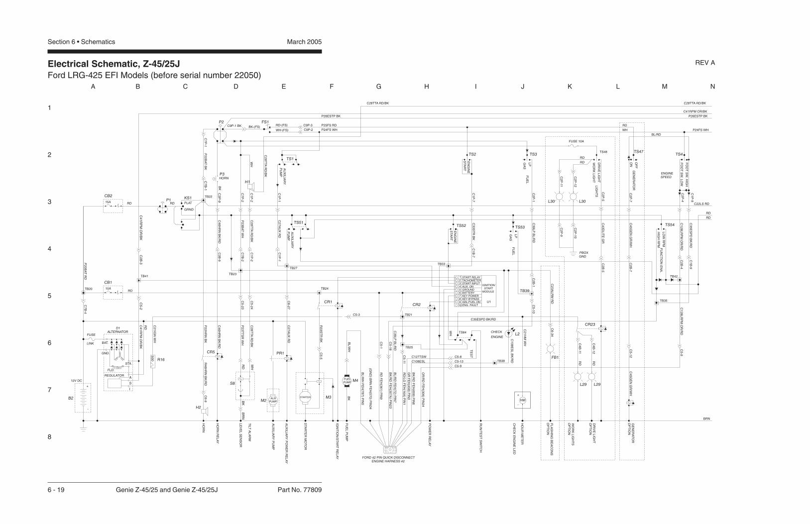
Electrical Schematic, Z-45/25JFord LRG-425 EFI Models (before serial number 22050)
1
2
3
4
5
6
7
8
A B C D E F G H I J K L M N
March 2005Section 6 • Schematics
6 - 19 Genie Z-45/25 and Genie Z-45/25J Part No. 77809
REV A
FO
OT
SW
.H
IGH
FO
OT
SW
.L
OW
HIG
HR
PM
LO
WR
PM
FU
NC
TIO
NE
NA
.
LP
FU
EL
GA
S
LP
FU
EL
GA
S
EN
GIN
ES
TA
RT
EN
GIN
ES
TA
RT
C1
B-7
AU
XIL
IAR
YP
UM
P
AU
XIL
IAR
YP
UM
P
P2
3T
TS
RW
H
HO
RN
RE
LA
Y
LE
VE
LS
EN
SO
R
HO
RN
15A
STA.
A
I
S
FLD.
REGULATOR
+
-
RD
P2
0B
AT
RD
TB20
GND.
BAT.
D1ALTERNATOR
LINK
FUSE
50
0
R4
6H
RN
BK
/RD
C2
1IG
NW
H
C4
1R
PM
OR
/BK
RD
CR5
C4
6H
RN
BK
/RD
CB1
RD
CB2
15A
TB41TB23
KS1
PLAT
GRND
P1RD
P3HORN
BK
TB22
P2
2B
AT
BK
BK-(FS)C9P-1 BK
GE
NE
RA
TO
RO
PT
ION
FL
AS
HIN
GB
EA
CO
NS
OP
TIO
N
HO
UR
ME
TE
R
RU
N/T
ES
TS
WIT
CH
PO
WE
RR
EL
AY
IGN
ITIO
N/S
TA
RT
RE
LA
Y
STA
RT
ER
MO
TO
R
AU
XIL
IAR
YP
UM
P
AU
XIL
IAR
YP
OW
ER
RE
LA
Y
FORD 42 PIN QUICK DISCONNECTENGINE HARNESS #2
TB35
TS2
GROUNDAUX. ON
KEY POWERBATTERY
TACHOMETER
IGN./FUEL ONENG. FAULT
KEY BYPASS
START INPUT
START RELAY
TS64
4
PR1
C2
7A
UX
RD
C2
8T
TA
RD
/BK
CR1
R3
3S
TR
BK
RD
/LG
FE
H(1
6A
)P
IN1
BL
/RD
FE
H(7
2)
PIN
7
BK
/RD
FE
H(3
07
A)
PIN
23
RD
FE
H(3
61
)P
IN9
BK
/RD
FE
H(6
58
)P
IN6
GR
FE
H(4
58
)P
IN3
TB21
TB25
8765
109
CR2
TS51
TB27
TS1
WH
TS52
1
2
TB33
3 C2
3A
LR
MR
D
IGNITION/START
MODULE
C5-13
L2T
ES
T
C1
08
ES
LB
K/R
D
C2
1H
MW
H
C4
5G
EN
GR
/WH
FB1
TS53
TB39
TS47
RD-(FS)FS1
(GN
D)
BR
NF
EH
(57
0)
PIN
34
TS3
CH
EC
KE
NG
INE
LE
D
12V DC
TIL
TA
LA
RM
+
_
P2
2H
RN
BK
RD
WH
BR
NB
K
BL
/WH
FE
H(7
87
)P
IN5
FUELPUMP
AUXPUMP
BL
/WH
BK
FU
EL
PU
MP
P2RD
WHC
2P
-4
C1
P-9
C3
5E
SP
DB
K/R
D
TS54
ENGINESPEED
TS4
P24FS WH
P26ESTP BK
C41RPM OR/BK
C22LS RD
RD
RD
BRN
C1
28
LR
PM
OR
/RD
C4
5G
EN
GR
/WH
C2
P-7
C2
P-1
C3
9L
PB
L/R
D
C1
P-7
C3
3S
TR
BK
C1
P-1
C2
7A
UX
RD
C1
P-2
C2
8T
TA
RD
/BK
C7
P-2
P2
3B
AT
WH
C3
P-9
C4
6H
RN
BK
/RD
C4
1R
PM
OR
/BK
OR
/RD
FE
H(3
06
)P
IN2
4
TB42
P26ESTP BK
P25FS RD
P24FS WHC9P-2
C9P-3
C7
P-1
C28TTA RD/BK C28TTA RD/BK
C5-9
C1
28
LR
PM
OR
/RD
C35ESPD BK/RD
C1
B-9
C2
B-4
C5
-9
C5
-12
C2
B-7
C2
B-1
C5
-10
C6
-34
C5-8
C7
B-4
C2
B-3
C5
-2
C2
8T
TA
RD
/BK
C5
-5
C6
-9
C5
-23
C5
-24
C6
-27
C1
P-1
C1
P-2
C7
B-2
C3
B-9
C5-3
C5
-11
C3
9L
PB
L/R
D
C7
B-1
C5
-1
TB38
B2
R16
M3M2
S8M4
U1
C5
-18
FUSE 10A
TS48
WO
RK
LIG
HT
ON
DR
IVE
LIG
HT
OF
F
LIG
HT
S
GE
NE
RA
TO
R
L30
C2
P-1
2
C2
P-11
C2
P-5
RD
RD
L30
L29
RD
C4
B-1
2
C2
B-5
C4
3D
LIT
EG
R
C2
P-1
0
PBOXGND
C2
P-9
WO
RK
LIG
HT
SO
PT
ION
DR
IVE
LIG
HT
OP
TIO
N
L29
RD
C4
B-11
CR23
C127TSW
C108ESL
TB24
BL/RD
WH CHECK
ENGINE
STARTER
HM
WH-(FS)
H2
H1

Electrical Schematic, Z-45/25JFord LRG-425 EFI Models (before serial number 22050)
1
2
3
4
5
6
7
8
N M L K J I H G F E D C B A
Part No. 77809 Genie Z-45/25 and Genie Z-45/25J 6 - 20
March 2005 Section 6 • Schematics
REV A
P24FS WH
P26ESTP BK
C41RPM OR/BK
C28TTA RD/BK
BRN
RD
RD
RD
C1
B-1
0
TB1
C3
B-1
2
C3
B-1
0
C3
B-11
BK
-4
WH
-6TB8TB15TB17
DR
IVE
LIM
ITS
WIT
CH
BO
OM
RE
TR
AC
T
C6
TR
FW
H/R
D
PR
IMA
RY
BO
OM
DO
WN
PR
IMA
RY
BO
OM
UP
SE
CO
ND
AR
YB
OO
M
SE
CO
ND
AR
YD
OW
N
LS
4-S
EC
ON
DA
RY
BO
OM
UP
DR
IVE
LIM
ITS
WIT
CH
LS
1-P
RIM
AR
YB
OO
ME
XT
EN
D
DR
IVE
LIM
ITS
WIT
CH
LS
2-P
RIM
AR
YB
OO
MU
P
LS
3-D
RIV
EE
NA
BL
E
PL
AT
LE
VE
LD
OW
N
DE
SC
EN
TA
LA
RM
OP
TIO
N
JIB
BO
OM
DO
WN
/P
LA
TF
OR
MR
OTA
TE
RIG
HT
JIB
BO
OM
UP
/P
LA
TF
OR
MR
OTA
TE
RIG
HT
C7
PB
EB
K
C8
PB
RB
K/W
H
C1
5P
LD
OR
/BK
C1
4P
LU
OR
C1
7JU
GR
C1
8JD
GR
/BK
C5
-25
C2
2-1
C6
-19
H3
C2
2-2
PL
AT
LE
VE
LU
P
BO
OM
EX
TE
ND
C2
0-1
C2
0-2
C2
1-1
C2
3-1
C2
3-2
C2
1-2
C1
7-1
C1
6-1
C1
7-2
C1
6-2
C4
4D
AB
K
C6
-18
C6
-17
C6
-15
C6
-14
C6
-8
C6
-7
TB14
TB18 TB7
C1
PB
UR
D
C2
PB
DR
D/B
K
C3
PB
FR
D/W
H
C1
0S
BU
BL
C11
SB
DB
L/B
K
C1
0-1
WH
-6
C1
2S
BF
BL
/WH
FL
OW
CO
NT
RO
L
SE
CO
ND
AR
YU
P
LIM
ITS
WIT
CH
C11
-3 C6
-20
BK
-5
RD
C3
0-1C
6-1
3 C3
0-2
C1
9-2
C1
9-1
FL
OW
CO
NT
RO
LP
RIM
AR
YB
OO
M
FL
OW
CO
NT
RO
L
C1
8-2
C1
8-1
C1
2-1
C2
9-1
C1
3-1
C2
9-2
C1
3-2
C1
2-2
Y22
TB10
C6
-10
BK C1
0-2
BK
-7
C1
0-4
WH
-5
14
13
LS3
BK
-6
C6
-12
C6
-11
WH
-4
LS4
22
21
C11
-2
WH
-7
TB12
C6
-16
TB11
C6
-3
C6
-1
C6
-2
TB3
TB2
TB6
DR
IVE
ED
CR
EV
ER
SE
DR
IVE
ED
CF
OR
WA
RD
BR
AK
ER
EL
EA
SE
VA
LV
E
TR
AV
EL
AL
AR
MO
PT
ION
TU
RN
TA
BL
ER
OTA
TE
LE
FT
TU
RN
TA
BL
ER
OTA
TE
RIG
HT
TU
RN
TA
BL
ER
OTA
TE
C3
1R
EV
WH
/BK
C3
0F
WD
WH
C2
9M
SR
D/W
H
C3
2B
RK
WH
/RD
C3
2TA
WH
/RD
C3
7S
TC
BL
/BK
C3
6S
TC
CB
L
C4
TR
LW
H
C5
TR
RW
H/B
K
C2
8-1
C2
8-2
MO
TO
RS
TR
OK
E
ST
EE
RL
EF
T
ST
EE
RR
IGH
T
C1
4-1
C3
1-1
C1
5-1
C1
4-2
C3
1-2
C1
5-2
C2
5-1
C2
4-1
C2
5-2
C2
4-2
BR
N
BR
N
GR
OU
ND
RD
C2
6-1
C2
6-2
BK
H4 BK
RD
U4
C6
-5
C6
-4
C6
-6
C6
-37
C6
-36
C6
-29
TB5
TB4
C6
-32
C5
-20
C6
-33
C5
-21
TB32
PRIMARY BOOM UP/DOWN &TURNTABLE ROTATE
P2
4F
SW
H
CR27
P2
4F
SW
H
P2
6E
ST
PB
K
C1
5P
LD
OR
/BK
RE
TR
AC
T
EX
TE
ND
BO
OM
DO
WN
DO
WN
UP
UP
PL
AT
FR
OM
LE
VE
L
PL
AT
FR
OM
LE
VE
L
C4
B-6
C4
B-5
C4
B-2
C4
B-3
C3
B-8
TS59
C1
4P
LU
OR
C8
PB
RB
K/W
H
C4
P-2
C4
P-3
TS63
RE
TR
AC
T
EX
TE
ND
BO
OMC
4P
-6
C4
P-5
C3
P-8
TS9 TS13
C11
-1
C6
-40
C11
-4
DO
WN
UP
BO
OM
SE
CO
ND
AR
Y
LS121
C1
0-3
C3
B-7
22
OR BK
-6
C4
B-4
C2
B-2
C7
PB
EB
K
C2
2L
SR
D
BK
C1
6P
DR
EO
R/R
D
TS60 C1
2S
BF
BL
/WH
C11
SB
DB
L/B
K
C3
B-3
C3
B-2
C3
B-1
C3
PB
FR
D/W
H
C1
0S
BU
BL
C2
PB
DR
D/B
K
C1
PB
UR
D
TS61
C2
P-2
C40LSS OR
C3
P-7
C4
P-4
U13 JOYSTICK CONTROL CARDCELIFT/DRIVEOPTION
4
NC
23 4
3
J3
1B
RN
13
12
14
C3
P-1
2
C3
P-1
0
C3
P-11
C3
P-2
C3
P-3
C3
P-1
3
10 9
J1
8 7
BR
N
OR
YE
L
11 2
12
J2
6
1
J1
RD
OR
BR
N
BK
1
P26ESTP BK
SECONDARY BOOMUP/DOWN
OU
T
PW
R
GN
D
42 3 5 6 7
JC1
GN
D21
YO
UT
PW
R
XO
UT
43 65
JC2
RIG
HT
LE
FT
DR
IVE
EN
AB
LE
CD
E1
BL
DR
IVE
MO
DE
CD
E3
BL
/RD
CD
E2
BL
/BK
10
C3
7S
TC
BL
/BK
C2
9M
SR
D/W
H
C3
B-4
C3
B-6
C3
B-5
C1
B-11
C1
B-3
C6
TR
FW
H/R
D
C4
TR
LW
H
C5
TR
RW
H/B
K
TS62 C3
6S
TC
CB
L
C3
1R
EV
WH
/BK
C3
2B
RK
WH
/RD
C1
B-6
C1
B-5
C1
B-4
C7
B-3
C3
0F
WD
WH
BA
TG
ND
20
17
11
18
10
R4
C3
P-6
C3
P-4
C3
P-5
C1
P-1
0
C1
P-11
C1
P-3
9
45
13
14
J1
6
WH
BR
N
OR
BL
BL
16
15
19
C4
1R
PM
OR
/BK
C1
P-6
C1
P-5
C2
P-3
C1
P-4
C7
P-3
8
167
J1
15
5
7
DRIVE & STEERING
YO
UT
PW
R
GN
D
31 2 54
RK
OU
T6 7
JC3
P24FS WH
P26ESTP BK
TS14
LS2
22
21
JIB
VA
LV
ES
C1
8JD
GR
/BK
C1
7JU
GR
JD
AL
AR
MG
R/B
K
C1
9JS
VG
R/W
H
TS58
UP
DO
WN
JIB
BO
OM
RIG
HT
PL
AT
FO
RM
RO
TA
TE
LE
FT
C4
B-7
TS57
C2
B-6
TB44
C19JSV GR/WH
RIG
HT
PL
AT
FO
RM
RO
TA
TE
LE
FT
C4
P-7
JIB
VA
LV
ES
CR13TS7
UP
DO
WN
JIB
BO
OM
C2
P-6
GR
/BK
-44
TS8
BRN
WH
NCCR13
L1
TS15
C28TTA RD/BK
DO
WN
UP
PR
IMA
RY
BO
OM
LE
FT
RIG
HT
TU
RN
TA
BL
ER
OTA
TE
CR30NO
STEERROCKERSWITCHOPTION

Electrical Schematic, Z-45/25JFord LRG-425 EFI Models (before serial number 22050)
March 2005 Section 6 • Schematics


Electrical Schematic, Z-45/25JFord LRG-425 EFI Models (after serial number 22049)
1
2
3
4
5
6
7
8
A B C D E F G H I J K L M N
March 2005Section 6 • Schematics
6 - 21 Genie Z-45/25 and Genie Z-45/25J Part No. 77809
REV A
P2
3T
TS
RW
H
HO
RN
RE
LA
Y
LE
VE
LS
EN
SO
R
HO
RN
STA.
A
I
S
FLD.
REGULATOR
+
-
RD
P2
0B
AT
RD
TB20
GND.
BAT.LINK
FUSE
50
0
R4
6H
RN
BK
/RD
C2
1IG
NW
H
C4
1R
PM
OR
/BK
RD
CR5NO
CR5
C4
6H
RN
BK
/RD
CB115A
RD
CB215A
TB41TB23
KS1
PLAT
GRND
P1RD
P3HORN
BK
TB22
P2
2B
AT
BK
BK-(FS)C9P-1 BK
GE
NE
RA
TO
RO
PT
ION
FL
AS
HIN
GB
EA
CO
NS
OP
TIO
N
HO
UR
ME
TE
R
RU
N/T
ES
TS
WIT
CH
PO
WE
RR
EL
AY
IGN
ITIO
N/S
TA
RT
RE
LA
Y
STA
RT
ER
MO
TO
R
AU
XIL
IAR
YP
UM
P
AU
XIL
IAR
YP
OW
ER
RE
LA
Y
FORD 42 PIN QUICK DISCONNECTENGINE HARNESS #2
TB35
TS2
GROUNDAUX. ON
KEY PWR.BATTERY
TACHOMETER
IGN./FUEL ONENG. FAULT
KEY BYPASS
START INPUT
START RELAY
TS64
4
STARTERAUX
PUMP
PR1
C2
7A
UX
RD
PR1NO
C2
8T
TA
RD
/BK
CR1CR1NO
R3
3S
TR
BK
RD
/LG
FE
H(1
6A
)P
IN1
BL
/RD
FE
H(7
2)
PIN
7
BK
/RD
FE
H(3
07
A)
PIN
23
RD
FE
H(3
61
)P
IN9
BK
/RD
FE
H(6
58
)P
IN6
GR
FE
H(4
58
)P
IN3
TB21
TB25
CR2NO
8765
109
CR2
TS51
TB27
TS1
WH
TS52
1
2
TB33
3 C2
3A
LR
MR
D
U1IGNITION/
STARTMODULE
HM
C5-13
L2
TE
ST
C1
08
ES
LB
K/R
D
C2
1H
MW
H
C4
5G
EN
GR
/WH
FB1
TS53
TB39
TS47
RD-(FS)FS1
NOTE:1) All switches and contacts are shown with theboom in the stowed position and the keyswitch off.
(GN
D)
BR
NF
EH
(57
0)
PIN
34
TS3
CH
EC
KE
NG
INE
LE
D
B1DC12V
CHECKENGINE
TIL
TA
LA
RM
+
_
P2
2H
RN
BK
RD
WH
BR
NB
K
BL
/WH
FE
H(7
87
)P
IN5
FUELPUMP
BL
/WH
BK
FU
EL
PU
MP
P2RD
WHWH-(FS)
H2
H1
C2
P-4
C1
P-9
C3
5E
SP
DB
K/R
D
TS54
ENGINESPEED
TS4
P24FS WH
P26ESTP BK
C41RPM OR/BK
C22LS RD
BRN
C1
28
LR
PM
OR
/RD
C4
5G
EN
GR
/WH
C2
P-7
GE
NE
RA
TO
RO
N
OF
F
C2
P-1
C3
9L
PB
L/R
D
C1
P-7
C3
3S
TR
BK
C1
P-1
C2
7A
UX
RD
C1
P-2
C2
8T
TA
RD
/BK
C7
P-2
P2
3B
AT
WH
C3
P-9
C4
6H
RN
BK
/RD
C4
1R
PM
OR
/BK
OR
/RD
FE
H(3
06
)P
IN2
4
TB42
P26ESTP BK
P25FS RD
P24FS WHC9P-2
C9P-3
C7
P-1
C28TTA RD/BK C28TTA RD/BK
C5-9
FO
OT
SW
ITC
HH
IGH
FO
OT
SW
ITC
HL
OW
HIG
HR
PM
LO
WR
PM
FU
NC
TIO
NE
NA
BL
E
C1
28
LR
PM
OR
/RD
C35ESPD BK/RD
C1
B-9
C2
B-4
C5
-9
C5
-12
LP
FU
EL
GA
S
LP
FU
EL
GA
S
C2
B-7
C2
B-1
C5
-10
EN
GIN
ES
TA
RT
EN
GIN
ES
TA
RT
EN
GIN
ES
TA
RT
C1
B-7
C6
-34
C5-8
C7
B-4
C2
B-3
C5
-2
C2
8T
TA
RD
/BK
AU
XIL
IAR
YP
UM
P
AU
XIL
IAR
YP
UM
P
C5
-5
C6
-9
C5
-23
C5
-24
C6
-27
C1
P-1
C1
P-2
C7
B-2
C3
B-9
C5-3
C5
-11
C3
9L
PB
L/R
D
C7
B-1
C5
-1
TB38
D1ALTERNATOR
R16
M3
M2
S8M4
C5
-18
FUSE 10A (ONLY ON WORKLIGHTS)
TS48
WO
RK
LIG
HT
DR
IVE
LIG
HT
LIG
HT
SL30
C2
P-1
2
C2
P-1
1
C2
P-5
RD
RD
L30
CR23
L29
RD
C4
B-1
2
C2
B-5
C4
3D
LIT
EG
R
C2
P-1
0
PBOX GND
C2
P-9
WO
RK
LIG
HT
SO
PT
ION
DR
IVE
LIG
HT
OP
TIO
N
L29
RD
C4
B-11
CR23NO
C1B & C1P - GRAYC2B & C2P - BLACKC3B & C3P - GREENC4B & C4P - BROWN
C127TSW
C108ESL
TB24
BL/RD
WH
C1
34
PW
RB
L/R
DC
2B
-5R
DC
2P
-5
L4
TB134
FUSE 10A

Electrical Schematic, Z-45/25JFord LRG-425 EFI Models (after serial number 22049)
1
2
3
4
5
6
7
8
N M L K J I H G F E D C B A
Part No. 77809 Genie Z-45/25 and Genie Z-45/25J 6 - 22
March 2005 Section 6 • Schematics
REV A
P26ESTP BK
C41RPM OR/BK
C28TTA RD/BK
BRN
RD
RD
BK
P24FS WH
WH
-4
BO
OM
RE
TR
AC
T
CR33
PL
AT
FO
RM
RO
TA
TE
RIG
HT
AN
DJIB
BO
OM
DO
WN
PL
AT
FO
RM
RO
TA
TE
LE
FT
AN
DJIB
BO
OM
UP
3
NOTES:1. ALL LIMIT SWITCHES SHOWNWITH BOOM IN STOWED POSITIONEXCEPT AS NOTED.
SWITCH SHOWN WITH BOOMROTATED PAST EITHER NON-STEERWHEEL.
ROCKER STEER OPTION ONLY.
2
C1B & C1P - GRAYC2B & C2P - BLACKC3B & C3P - GREENC4B & C4P - BROWN
C6
-19
DE
SC
EN
TA
LA
RM
OP
TIO
N
JIB
BO
OM
VA
LV
E
H3
C2
2-2
C5
-25
C2
3-2
PL
AT
FO
RM
LE
VE
LD
OW
N
PL
AT
FO
RM
LE
VE
LU
P
BO
OM
EX
TE
ND
C2
1-2
C2
0-2
C1
6-2
C1
7-2
C4
4D
AB
K
C1
8JD
GR
/BK
C2
2-1
C2
3-1
C1
7JU
GR
C6
-18
C6
-17
C1
5P
LD
OR
/BK
C1
4P
LU
OR
C2
1-1
C2
0-1
C8
PB
RB
K/W
H
C1
6-1
C1
7-1
C7
PB
EB
K
C6
-15
C6
-14
C6
-8
C6
-7
C6
-20
BK
-5
C6
-13
LS
4-S
EC
ON
DA
RY
BO
OM
UP
DR
IVE
LIM
ITS
WIT
CH
LS
1-P
RIM
AR
YB
OO
ME
XT
EN
DD
RIV
EL
IMIT
SW
ITC
H
LS
2-P
RIM
AR
YB
OO
MU
PD
RIV
EL
IMIT
SW
ITC
H
LS
3-D
RIV
EE
NA
BL
EL
IMIT
SW
ITC
H
SE
CO
ND
AR
YB
OO
MU
P
SE
CO
ND
AR
YB
OO
MS
EL
EC
TR
EL
AY
SE
CO
ND
AR
YB
OO
MD
OW
N
C1
8-2
C1
9-2
PR
IMA
RY
BO
OM
UP
PR
IMA
RY
BO
OM
SE
LE
CT
RE
LA
Y
PR
IMA
RY
BO
OM
DO
WN
TU
RN
TA
BL
ER
OTA
TE
SE
LE
CT
RE
LA
Y
TU
RN
TA
BL
ER
OTA
TE
RIG
HT
TU
RN
TA
BL
ER
OTA
TE
LE
FT
C1
3-2
C1
4-2
C1
2-2
C1
5-2
BK LS3
C6
-10
C6
-11
C1
0-1
WH
-6RD
C11
-3B
K-7
C1
0-2
14
C11
SB
DB
L/B
K
C1
0S
BU
BL
C1
8-1
C1
9-1
LS2
22
21
C1
0-4
WH
-5
BK
-6
13
2
8587a 87
8630
CR37
C4
TR
LW
H
C5
TR
RW
H/B
K
C2
PB
DR
D/B
K
C1
3-1
C1
4-1
C1
2-1
C1
5-1
C1
PB
UR
D
8587a 87
8630
C6
-2
C6
-5
C6
-4
C6
-1
CR32
8587a 87
8630
BR
AK
ER
EL
EA
SE
VA
LV
E
TR
AV
EL
AL
AR
MO
PT
ION
MO
TO
RS
TR
OK
E
ST
EE
RL
EF
T
ST
EE
RR
IGH
T
C2
4-2
C2
5-2
C2
8-2
C2
6-2
DR
IVE
ED
CR
EV
ER
SE
DR
IVE
ED
CF
OR
WA
RD
GR
OU
ND
BR
N
BR
N
BK
RD
C3
7S
TC
BL
/BK
C3
6S
TC
CB
L
C2
4-1
C2
5-1
C2
9M
SR
D/W
H
C3
2B
RK
WH
/RD
C3
2TA
WH
/RD
C2
8-1
C2
6-1 H4
C6
-37
C6
-36
C6
-29
C6
-32
C6
-33
C3
1R
EV
WH
/BK
C3
0F
WD
WH
RD
BK
U4
C5
-20
C5
-21
TB5
C5
TR
RW
H/B
K
RIG
HT
PL
AT
FO
RM
RO
TA
TE
LE
FT
JIBVALVE
One valveremoved afterserial number22565
RE
TR
AC
T
EX
TE
ND
BO
OM
UP
DO
WN
JIB
BO
OM
GR
/BK
-44
J3 J1 J1
JD
AL
AR
MG
R/B
K
C1
9JS
VG
R/W
H
UP
DO
WN
JIB
BO
OM
RIG
HT
PL
AT
RO
TA
TE
LE
FT
C1
5P
LD
OR
/BK
RE
TR
AC
T
EX
TE
ND
BO
OM
DO
WN
UP
PL
AT
FR
OM
LE
VE
L
C1
4P
LU
OR
C8
PB
RB
K/W
H
C7
PB
EB
K
C2
2L
SB
K
TB18
TB17
C4
B-5
C4
B-7
TB14
C4
B-6
TB15
C4
B-2
C4
B-3
TB7
TB8
C3
B-8
C3
B-7
C2
B-6
TB44
C1
7JU
GR
TS57
TS58
C4
P-7
C19JSV GR/WH
C4
P-5
C1
8JD
GR
/BK
C4
P-2
C4
P-3
TS59 TS63
C4
P-6
C2
P-6
C3
P-8
C3
P-7
DO
WN
UP
SE
CO
ND
AR
YB
OO
M
C1
6P
DR
EO
R/R
D
C1
2S
BF
BL
/WH
C11
SB
DB
L/B
K
DO
WN
UP
PR
IMA
RY
BO
OM
C3
PB
FR
D/W
H
C1
0S
BU
BL
C2
PB
DR
D/B
K
C1
PB
UR
D
LE
FT
RIG
HT
TU
RN
TA
BL
ER
OTA
TE
LS1
C1
0-3
WH
-6
21
WH
-7
22
LS4
C11
-2
C6
-16
22BK
-4
C4
B-4
TB10
TB12
TB11
C3
B-1
0
C3
B-1
1
C11
-4
21
OR BK
-6
C6
-40
C11
-1
TB3
C3
B-1
2
C3
B-3
C3
B-2
C3
B-1
TB2
TB6
TB1
C3
B-5
14
BK
C2
B-2
C40LSS OR
TS60
U13 JOYSTICK CONTROL CARD
C2
P-2
C4
P-4
CELIFT/DRIVEOPTION
4 3
C3
P-1
0
C3
P-1
1
12
13
TS61 TS62
20
R4
J2
C3
P-1
2
C3
P-2
C3
P-3
C3
P-1
8 7 6
C3
P-5
10
WH
CR13
TS7 TS8
BRN
TS9
CR13NC
TS13
6
P2
4F
SW
H
P2
6E
ST
PB
K
CR30NO
3 4
CR27NC
P2
4F
SW
H
BR
N
BR
N
OR
YE
L
12
10 9 3
1 2 3 4 5
PW
R
GN
D
OU
T
JC1
SECONDARY BOOMUP/DOWN
P26ESTP BK
BR
N1
2
7 21
GN
D
RD
OR
BK
211 1
543 6 7
PW
R
XO
UT
YO
UT
PRIMARY BOOM UP/DOWNAND TURNTABLE ROTATE
JC2
J1
C4
1R
PM
OR
/BK
J1C
37
ST
CB
L/B
K
C2
9M
SR
D/W
H
C6
TR
FW
H/R
D
C3
6S
TC
CB
L
C3
1R
EV
WH
/BK
C3
2B
RK
WH
/RD
C3
0F
WD
WH
BA
TG
ND
C3
B-6
C1
B-1
0
C1
B-1
1
TB32
C1
B-3
C1
B-6
C1
B-5
C1
B-4
C7
B-3
C3
P-6
C1
P-1
0
C1
P-1
1
18
119 17
C1
P-3
C1
P-6
20
19
C1
P-5
C2
P-3
C1
P-4
C7
P-3
15
16 5
C28TTA RD/BK
RIG
HT
LE
FT
DR
IVE
EN
AB
LE
RK
OU
T
L1
7
WH
BR
N
OR
BL
BL
14 5
13 4
GN
D21 3 4 5 6
PW
R
YO
UT
DR
IVE
MO
DE
CD
E3
BL
/RD
CD
E2
BL
/BK
6 7
3
16 8
CD
E1
BL
P24FS WH
P26ESTP BK
DRIVE & STEERING
JC3TS15
15
TS14
WH
BK

Electrical Schematic, Z-45/25JFord LRG-425 EFI Models (after serial number 22049)
March 2005 Section 6 • Schematics

Ground Control Box Terminal Strip Wiring Diagram, Z-45/25JFord LRG-425 EFI Models (before serial number 22050)
March 2005Section 6 • Schematics
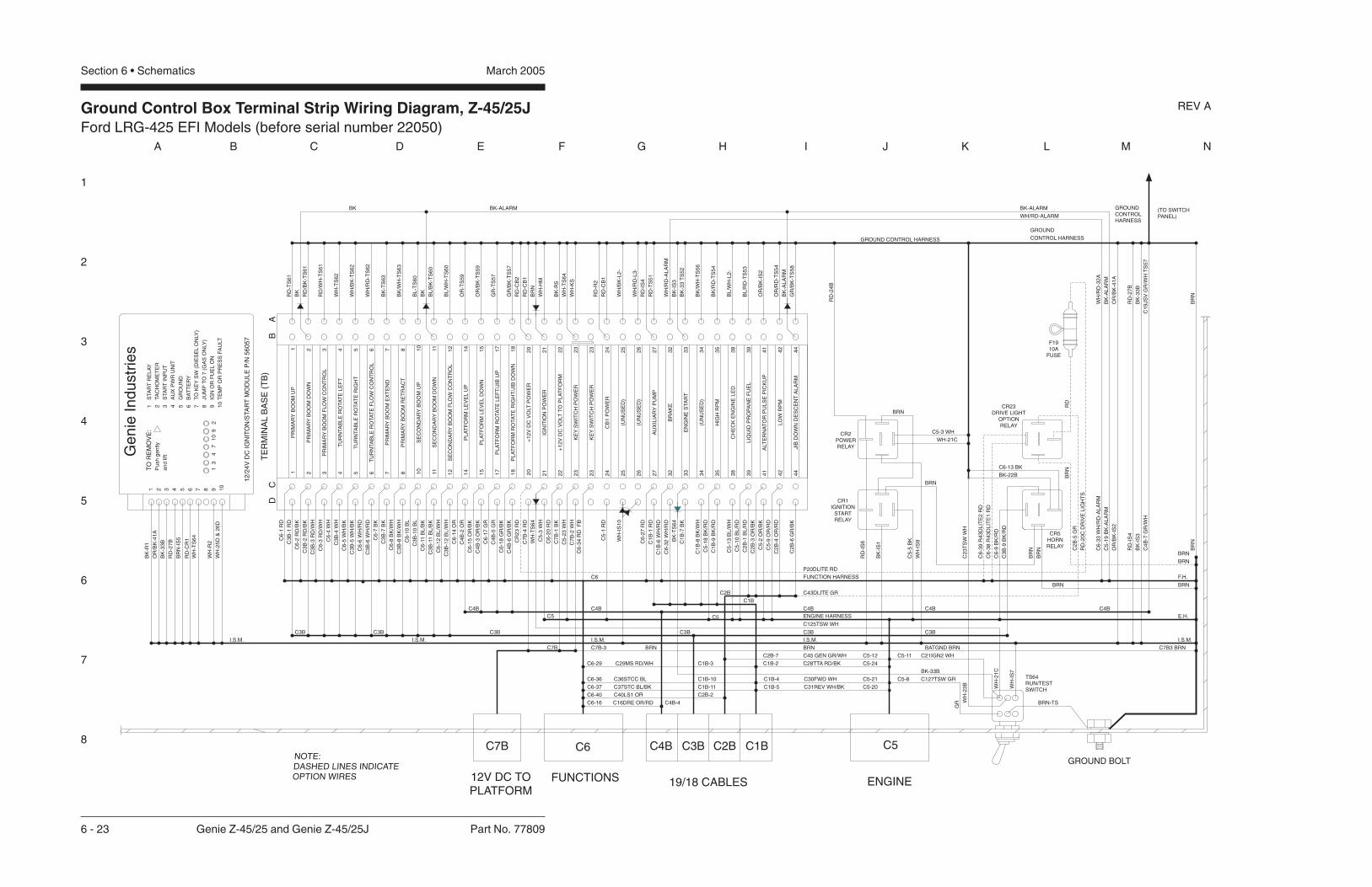
Ground Control Box Terminal Strip Wiring Diagram, Z-45/25JFord LRG-425 EFI Models (before serial number 22050)
1
2
3
4
5
6
7
8
A B C D E F G H I J K L M N
March 2005Section 6 • Schematics
6 - 23 Genie Z-45/25 and Genie Z-45/25J Part No. 77809
REV A
DC
PR
IMA
RY
BO
OM
UP
1 2 3 4 5 6 7 8 10
PR
IMA
RY
BO
OM
DO
WN
PR
IMA
RY
BO
OM
FL
OW
CO
NT
RO
L
TU
RN
TA
BL
ER
OTA
TE
LE
FT
TU
RN
TA
BL
ER
OTA
TE
RIG
HT
TU
RN
TA
BL
ER
OTA
TE
FL
OW
CO
NT
RO
L
PR
IMA
RY
BO
OM
EX
TE
ND
PR
IMA
RY
BO
OM
RE
TR
AC
T
SE
CO
ND
AR
YB
OO
MU
P
+1
2V
DC
VO
LT
PO
WE
R
PL
AT
FO
RM
RO
TA
TE
RIG
HT
/JIB
DO
WN
PL
AT
FO
RM
RO
TA
TE
LE
FT
/JIB
UP
PL
AT
FO
RM
LE
VE
LD
OW
N
PL
AT
FO
RM
LE
VE
LU
P
SE
CO
ND
AR
YB
OO
MF
LO
WC
ON
TR
OL
SE
CO
ND
AR
YB
OO
MD
OW
N
2011
15
17
18
14
12
AU
XIL
IAR
YP
UM
P
KE
YS
WIT
CH
PO
WE
R
IGN
ITIO
NP
OW
ER
21
25
27
26
23
24
HIG
HR
PM
(UN
US
ED
)
EN
GIN
ES
TA
RT
BR
AK
E
39
35
38
33
34
32
LO
WR
PM
ALT
ER
NA
TO
RP
UL
SE
PIC
KU
P4
1
44
42
BA
C6
-1R
D
C3
B-1
RD
C6
-2R
D/B
K
C3
B-2
RD
/BK
C3
B-3
RD
/WH
C6
-4W
H
C3
B-4
WH
C6
-5W
H/B
K
C3
B-5
WH
/BK
C6
-6W
H/R
D
C6
-7B
K
C3
B-7
BK
C6
-8B
K/W
H
C3
B-8
BK
/WH
C6
-10
BL
C3
B-1
0B
L
C6
-11
BL
/BK
C3
B-1
1B
L/B
K
C6
-12
BL
/WH
C3
B-1
2B
L/W
H
C6
-14
OR
C6
-15
OR
/BK
C6
-17
GR
C4
B-5
GR
C6
-18
GR
/BK
C4
B-6
GR
/BK
C1
B-1
RD
C7
B-4
RD
C5
-3W
H
C7
B-1
BK
C7
B-2
WH
C1
B-6
WH
/RD
C6
-32
WH
/RD
BK
-TS
64
C1
B-7
BK
C5
-18
BK
/RD
C5
-10
BL
/RD
C2
B-3
OR
/BK
C5
-2O
R/B
K
C5
-9O
R/R
D
C2
B-6
GR
/BK
RD
-TS
61
RD
/BK
-TS
61
WH
-TS
62
WH
/BK
-TS
62
BK
-TS
63
BK
/WH
-TS
63
BL
-TS
60
BL
/BK
-TS
60
BL
/WH
-TS
60
OR
-TS
59
OR
/BK
-TS
59
GR
-TS
57
GR
/BK
-TS
57
RD
-CB
1
BK
/RD
-TS
54
RD
/WH
-TS
61
WH
/RD
-TS
62
C3
B-6
WH
/RD
C1B
C4B
C5
BATGND BRN
ENGINE HARNESS
FUNCTION HARNESS
RD
-27
B
GROUND CONTROL HARNESS
(TO SWITCHPANEL)
CONTROL HARNESS
E.H.
F.H.
OR
/BK
-IS
2
TE
RM
INA
LB
AS
E(T
B)
1 2 3 4 5 6 7 8 10
11
15
17
18
14
12
20
24
26
27
25
23
21
38
39
34
35
32
33
44
42
41
GROUND
GROUNDCONTROLHARNESS
1 2 3 4 5 6 7 8 9 10
1 2 3 4 5 6 7 8 9 10
STA
RT
RE
LA
Y
TA
CH
OM
ET
ER
STA
RT
INP
UT
AU
XP
WR
UN
IT
GR
OU
ND
BA
TT
ER
Y
TO
KE
YS
W(D
IES
EL
ON
LY)
JU
MP
TO
7(G
AS
ON
LY)
IGN
OR
FU
EL
ON
TE
MP
OR
PR
ES
SF
AU
LT1
34
71
09
2
12
/24
VD
CIG
NIT
ON
/STA
RT
MO
DU
LE
P/N
56
05
7
Ge
nie
Ind
ustr
ies
TO
RE
MO
VE
:
Pu
sh
ge
ntly
an
dlif
t
BK
-R1
OR
/BK
-41
A
BK
-33
B
RD
-27
B
BR
N-I
S5
WH
-R2
RD
-CR
1
C6
-3R
D/W
H
C4
B-2
OR
C4
B-3
OR
/BK
C6
-27
RD
WH
-KS
RD
-TS
51
BK
-33
TS
52
OR
/BK
-41
A
RD
-IS
4
OR
/BK
-IS
2
BK
-IS
1
WH
-IS
9
C5
-5B
K
C7B3 BRN
I.S.M. I.S.M. I.S.M. I.S.M.
C6
C4B
C5
C7B
WH
/RD
-AL
AR
M
BK-ALARMBK-ALARMBK
C6
-33
WH
/RD
-AL
AR
M
C5
-19
BK
-AL
AR
M
WH
/RD
-32
A
BK
-AL
AR
M
C6
-34
RD
FB
BK
BK
WH/RD-ALARM
JIB
DO
WN
DE
SC
EN
TA
LA
RM
BR
NB
RN
GROUND BOLTNOTE:DASHED LINES INDICATEOPTION WIRES
RD
-IS
6
RD
-IS
4
FUNCTIONS ENGINE19/18 CABLES
C5C6 C2B C1BC3BC4B
12V DC TOPLATFORM
C7B
CB
1P
OW
ER
WH
/RD
-L3
-(U
NU
SE
D)
C3BC3B C3B C3B C3B
C2B
C5
-13
BL
/WH
C2
B-1
BL
/RD
CH
EC
KE
NG
INE
LE
D
LIQ
UID
PR
OP
AN
EF
UE
LB
L/R
D-T
S5
3
BL
/WH
-L2
-
(UN
US
ED
)
CR5HORNRELAY
BR
N
WH-21C
RD
-24
B
C6-13 BK
C6
-9B
K/R
D
BRN
BRNBRN
BR
N
C3
B-9
BK
/RD
C3B
+1
2V
DC
VO
LT
TO
PL
AT
FO
RM
22
22
C5
-23
WH
BK-22B
C7B-3
BRN
CR1
STARTRELAY
IGNITION
CR2
RELAYPOWER
C16DRE OR/RDC6-16 C4B-4
C1
9JS
VG
R/W
HT
S5
7C
4B
-7G
R/W
H
C43DLITE GR
C4B C4BC4B
C36STCC BLC6-36 C1B-10
C37STC BL/BKC6-37 C1B-11
C30FWD WHC1B-4 C5-21
C31REV WH/BKC1B-5 C5-20
C28TTA RD/BK C5-24C1B-2C29MS RD/WHC6-29 C1B-3
C40LS1 ORC6-40 C2B-2C
1B
-8B
K/W
H
BRN
WH
-25
D&
26
D
C1
B-9
BK
/RD
C6
-20
RD
WH
-21
C
WH
-23
B
WH
-IS
7
BRN-TS
GR
TS64RUN/TESTSWITCH
BR
N
BK
/WH
-TS
56
WH
/BK
-L2
-
C5-3 WH
BK
-R5
OR
/RD
-TS
54
BRN
CR23DRIVE LIGHT
OPTIONRELAY
C6
-38
R4
3D
LIT
E1
RD
C6
-39
R4
3D
LIT
E2
RD
BRN
BR
NR
D
P20DLITE RD
C2
B-5
GR
WH
-TS
64
C5-8 C127TSW GR
C2
3T
SW
WH
C125TSW WHW
H-I
S1
0
C2
B-4
OR
/RD
F1910A
FUSE
C45 GEN GR/WH C5-12C2B-7
RD
-R2
RD
-CB
1
RD
-CB
2
C5
-1R
D
CR
23
RD
RD
-20
CD
RIV
EL
IGH
TS
WH
-HM
WH
-TS
64
C5-11 C21IGN2 WH
KE
YS
WIT
CH
PO
WE
R2
32
3
GR
/BK
-TS
58
BK
-AL
AR
M
I.S.M.
BRN
BK-33B
WH
-TS
64
BK
-33
BB
K-I
S3
BK
-IS
3

Ground Control Box Switch Panel Wiring Diagram, Z-45/25JFord LRG-425 EFI Models (before serial number 22050)
1
2
3
4
5
6
7
8
N M L K J I H G F E D C B A
Part No. 77809 Genie Z-45/25 and Genie Z-45/25J 6 - 24
March 2005 Section 6 • Schematics
REV A
HO
UR
ME
TE
R
KE
YS
WIT
CH
KS
1
GR
OU
ND
CO
NT
RO
LB
OX
HA
RN
ES
S(T
OT
ER
MIN
AL
ST
RIP
)
BK
/RD
-35
A
RD
-20
B
RD
RD
RD
RD
RD
RD
RD
-20
A
BK
-33
A
RD
RD
RD
RD
RD
RD
RD
RD
RD
RD
RD
RDRD
RDRDRD
RDRDRD
RD
RDRD
RD
RDRD
RD
BRN
WH-CR2W
H-2
1
BR
N
RD
RD
RD
RD
RD
GR
/BK
-18
GR
/BK
-18
A
RD
RD
GR
-17
GR
-17
A
C1
9JS
VG
R/W
HC
4B
-7G
R/W
H
OR
-14
A
RD
OR
/BK
-15
A
RDRD
BL
/WH
-12
A
BL
/BK
-11
A
RD
BL
-10
A
RD
RD
RD
RDRD
RD
RDRDRDRDRD
WH
/RD
-6
WH
-4
WH
/BK
-5
WH
/RD
-6A
WH
-4A
WH
/BK
-5A
RDRD
RDRD
RDRD RD
RDRD RD
RD
RD
RD
RD
BK
/WH
-8A
BK
-7A
RD
-1A
RD
RD
/WH
-3A
RD
/BK
-2A
RD
BK/WH-8
BK-7
RD
RD
WH-23
WH
-23
A
RD
BK
-22
RD
RD
RD
-27
RD
-27
A
RD
RD
RD
RD
KS
1
TS
59
LE
VE
LP
LA
TF
OR
M
TS
57
PL
AT
FO
RM
RO
TA
TE
CB
2C
IRC
UIT
BR
EA
KE
RC
ON
TR
OL
S,
15
A
CB
1
BR
EA
KE
RE
NG
INE
,1
5A
CIR
CU
IT
TS
54
EN
AB
LE
FU
NC
TIO
N
TS
52
EN
GIN
ES
TA
RT
TS
60
SE
CO
ND
AR
YB
OO
MU
P/D
OW
N
TS
62
RO
TA
TE
TU
RN
TA
BL
E
TS
63
PR
IMA
RY
BO
OM
EX
TE
ND
/RE
TR
AC
T
TS
61
BO
OM
UP
/DO
WN
PR
IMA
RY
R4
FU
NC
TIO
NS
PE
ED
CO
NT
RO
LV
AR
IAB
LE
RE
SIS
TE
R
TS
51
AU
XIL
IAR
YP
OW
ER
P1
ST
OP
SW
ITC
H
STA
CK
ED
CO
NTA
CT
S
RD
RD
RD
RD
3 4NO
3 4NO
3
4NO
3 4NO
1
2
NC
1
2
NC
RD
RD
BL
/RD
-39
A
TS
53
FU
EL
SE
LE
CT
BL
/WH
-38
L2
EN
GIN
EL
ED
CH
EC
K
-+
RD
-24
A
OR
/RD
-42
A
GR
GRGR
GR/BK
RD
GR/BK
RD
GR/BK
RD
GR
/BK
TS
58
JIB
BO
OM
GR
/BK
-44
A

Ground Control Box Switch Panel Wiring Diagram, Z-45/25JFord LRG-425 EFI Models (before serial number 22050)
March 2005 Section 6 • Schematics

Ground Control Box Terminal Strip Wiring Diagram, Z-45/25JFord LRG-425 EFI Models (after serial number 22049)
March 2005Section 6 • Schematics
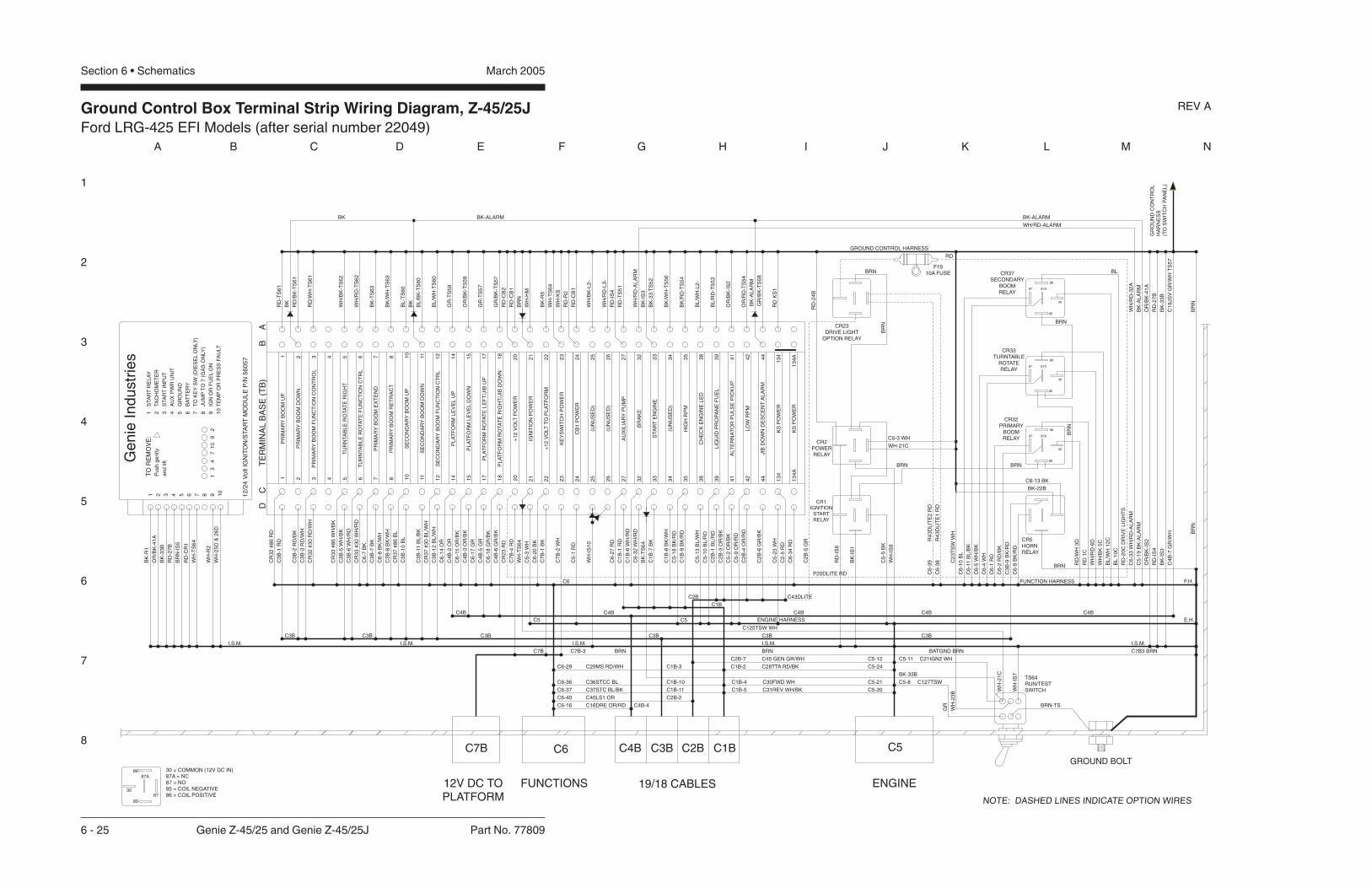
Ground Control Box Terminal Strip Wiring Diagram, Z-45/25JFord LRG-425 EFI Models (after serial number 22049)
1
2
3
4
5
6
7
8
A B C D E F G H I J K L M N
March 2005Section 6 • Schematics
6 - 25 Genie Z-45/25 and Genie Z-45/25J Part No. 77809
REV A
DC
PR
IMA
RY
BO
OM
UP
1 2 3 4 5 6 7 8 10
PR
IMA
RY
BO
OM
DO
WN
PR
IMA
RY
BO
OM
FU
NC
TIO
NC
ON
TR
OL
TU
RN
TA
BL
ER
OTA
TE
RIG
HT
TU
RN
TA
BL
ER
OTA
TE
FU
NC
TIO
NC
TR
L
PR
IMA
RY
BO
OM
EX
TE
ND
PR
IMA
RY
BO
OM
RE
TR
AC
T
SE
CO
ND
AR
YB
OO
MU
P
+1
2V
OLT
PO
WE
R
PL
AT
FO
RM
RO
TA
TE
RIG
HT
/JIB
DO
WN
PL
AT
FO
RM
RO
TA
TE
LE
FT
/JIB
UP
PL
AT
FO
RM
LE
VE
LD
OW
N
PL
AT
FO
RM
LE
VE
LU
P
SE
CO
ND
AR
YB
OO
MF
UN
CT
ION
CT
RL
SE
CO
ND
AR
YB
OO
MD
OW
N
2011
15
17
18
14
12
AU
XIL
IAR
YP
UM
P
KE
YS
WIT
CH
PO
WE
R
IGN
ITIO
NP
OW
ER
21
25
27
26
23
24
HIG
HR
PM
(UN
US
ED
)
STA
RT
EN
GIN
E
BR
AK
E
39
35
38
33
34
32
LO
WR
PM
ALT
ER
NA
TO
RP
UL
SE
PIC
KU
P4
1
44
42
BA
CR
32
#8
6R
D
C3
B-1
RD
C3
B-2
RD
/BK
C3
B-3
RD
/WH
CR
33
#8
6W
H/B
K
C3
B-5
WH
/BK
C3
B-6
WH
/RD
C6
-7B
K
C3
B-7
BK
C6
-8B
K/W
H
C3
B-8
BK
/WH
CR
37
#8
6B
L
C3
B-1
0B
L
C3
B-1
1B
L/B
K
CR
37
#3
0B
L/W
H
C3
B-1
2B
L/W
H
C6
-14
OR
C6
-15
OR
/BK
C6
-17
GR
C4
B-5
GR
C6
-18
GR
/BK
C4
B-6
GR
/BK
C1
B-1
RD
C7
B-4
RD
C5
-3W
H
C7
B-1
BK
C7
B-2
WH
C1
B-6
WH
/RD
C6
-32
WH
/RD
BK
-TS
64
C1
B-7
BK
C5
-18
BK
/RD
C5
-10
BL
/RD
C2
B-3
OR
/BK
C5
-2O
R/B
K
C5
-9O
R/R
D
C2
B-6
GR
/BK
RD
-TS
61
RD
/BK
-TS
61
WH
/BK
-TS
62
BK
-TS
63
BK
/WH
-TS
63
BL
-TS
60
BL
/BK
-TS
60
BL
/WH
-TS
60
OR
-TS
59
OR
/BK
-TS
59
GR
-TS
57
GR
/BK
-TS
57
RD
-CB
1
BK
/RD
-TS
54
RD
/WH
-TS
61
WH
/RD
-TS
62
CR
33
#3
0W
H/R
D
C1B
C4B
C5
BATGND BRN
ENGINE HARNESS
FUNCTION HARNESS
RD
-27
B
GROUND CONTROL HARNESS
E.H.
F.H.
OR
/BK
-IS
2
TE
RM
INA
LB
AS
E(T
B)
1 2 3 4 5 6 7 8 10
11
15
17
18
14
12
20
24
26
27
25
23
21
38
39
34
35
32
33
44
42
41
GR
OU
ND
CO
NT
RO
LH
AR
NE
SS
(TO
SW
ITC
HP
AN
EL
)
1 2 3 4 5 6 7 8 9 10
1 2 3 4 5 6 7 8 9 10
STA
RT
RE
LA
Y
TA
CH
OM
ET
ER
STA
RT
INP
UT
AU
XP
WR
UN
IT
GR
OU
ND
BA
TT
ER
Y
TO
KE
YS
W(D
IES
EL
ON
LY
)
JU
MP
TO
7(G
AS
ON
LY
)
IGN
OR
FU
EL
ON
TE
MP
OR
PR
ES
SF
AU
LT
13
47
10
92
12
/24
Vo
ltIG
NIT
ON
/STA
RT
MO
DU
LE
P/N
56
05
7
Ge
nie
Ind
ustr
ies
TO
RE
MO
VE
:
Pu
sh
ge
ntly
an
dlif
t
BK
-R1
OR
/BK
-41
A
BK
-33
B
RD
-27
B
BR
N-I
S5
WH
-R2
RD
-CR
1
CR
32
#3
0R
D/W
H
C4
B-2
OR
C4
B-3
OR
/BK
C6
-27
RD
WH
-KS
RD
-TS
51
BK
-33
TS
52
OR
/BK
-41
A
RD
-IS
4
OR
/BK
-IS
2
BK
-IS
1
WH
-IS
9
C5
-5B
K
C7B3 BRN
I.S.M. I.S.M. I.S.M. I.S.M.
C6
C4B
C5
C7B
WH
/RD
-AL
AR
M
BK-ALARMBK-ALARMBK
C6
-33
WH
/RD
-AL
AR
M
C5
-19
BK
-AL
AR
M
WH
/RD
-32
A
BK
-AL
AR
M
BK
BK
WH/RD-ALARM
BR
NB
RN
GROUND BOLT
NOTE: DASHED LINES INDICATE OPTION WIRES
RD
-IS
6
RD
-IS
4
FUNCTIONS ENGINE19/18 CABLES
C5C6 C2B C1BC3BC4B
12V DC TOPLATFORM
C7B
CB
1P
OW
ER
WH
/RD
-L3
-(U
NU
SE
D)
C3BC3B C3B C3B C3B
C2B
C5
-13
BL
/WH
C2
B-1
BL
/RD
CH
EC
KE
NG
INE
LE
D
LIQ
UID
PR
OP
AN
EF
UE
LB
L/R
D-T
S5
3
BL
/WH
-L2
-
(UN
US
ED
)
CR2POWERRELAY
CR1IGNITION
STARTRELAY
BR
N
WH-21C
RD
-24
B
BRN
C3B
+1
2V
OLT
TO
PL
AT
FO
RM
22
22
C7B-3
C16DRE OR/RDC6-16 C4B-4
C1
9JS
VG
R/W
HT
S5
7C
4B
-7G
R/W
H
C43DLITE
C4B C4BC4B
C36STCC BLC6-36 C1B-10
C37STC BL/BKC6-37 C1B-11
C30FWD WHC1B-4 C5-21
C31REV WH/BKC1B-5 C5-20
C28TTA RD/BK C5-24C1B-2C29MS RD/WHC6-29 C1B-3
C40LS1 ORC6-40 C2B-2
C1
B-8
BK
/WH
WH
-25
D&
26
D
C1
B-9
BK
/RD
C6
-20
BK
WH
-21
C
WH
-23
B
WH
-IS
7
BRN-TS
GR
TS64RUN/TESTSWITCH
BK
/WH
-TS
56
WH
/BK
-L2
-
C5-3 WH
BK
-R5
OR
/RD
-TS
54
BRN
R4
3D
LIT
E1
RD
R4
3D
LIT
E2
RD
P20DLITE RD
C2
B-5
GR
WH
-TS
64
C5-8 C127TSW
C2
3T
SW
WH
C125TSW WH
WH
-IS
10
C2
B-4
OR
/RD
C45 GEN GR/WH C5-12C2B-7
RD
-R2
RD
-CB
1
RD
-CB
2
C5
-1R
D
CR
23
RD
RD
-20
CD
RIV
EL
IGH
TS
WH
-HM
WH
-TS
64
C5-11 C21IGN2 WH
I.S.M.
BRN
BK-33B
WH
-TS
64
BK
-33
BB
K-I
S3
BK
-IS
3
CR23DRIVE LIGHT
OPTION RELAY
F1910A FUSE
C6-13 BK
BK-22B
RD
CR32PRIMARY
BOOMRELAY
CR33TURNTABLE
ROTATERELAY
CR37SECONDARY
BOOMRELAY
BRN
BRN
BR
N
RD
/WH
3D
RD
1C
C6
-2R
D/B
K
C6
-1R
D
30
85
87
86
87A
30 = COMMON (12V DC IN)87A = NC87 = NO85 = COIL NEGATIVE86 = COIL POSITIVE
C6
-5W
H/B
K
C6
-10
BL
C6
-4W
H
C6
-11
BL
/BK
WH
/RD
6D
WH
/BK
5C
BL
/WH
12
C
BL
10
C
30
85
87
86
87A
30
85
87
86
87A
30
85
87
86
87A
BLBRN
BR
N
13
4K
SP
OW
ER
13
4A
KS
PO
WE
R
RD
KS
1C
5-2
3W
H
C2
-5R
D
C6
-34
RD
BRN
C6
-38
C6
-39
CR5HORNRELAY
C3
B-9
BK
/RD
13
4A
13
4
C6
-9B
K/R
D
JIB
DO
WN
DE
SC
EN
TA
LA
RM
GR
/BK
-TS
58
BK
-AL
AR
M
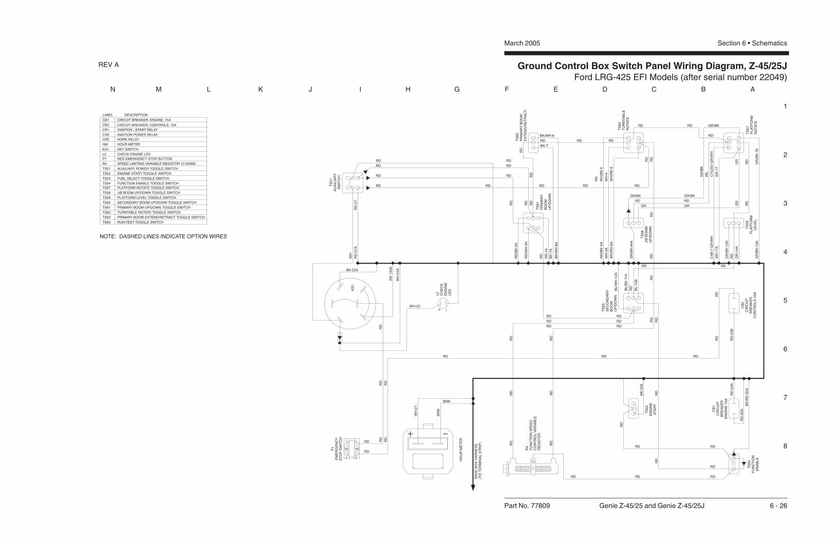
Ground Control Box Switch Panel Wiring Diagram, Z-45/25JFord LRG-425 EFI Models (after serial number 22049)
1
2
3
4
5
6
7
8
N M L K J I H G F E D C B A
Part No. 77809 Genie Z-45/25 and Genie Z-45/25J 6 - 26
March 2005 Section 6 • Schematics
REV A
HO
UR
ME
TE
R
BA
SE
BO
XH
AR
NE
SS
(TO
TE
RM
INA
LS
TR
IP)
BK
/RD
-35
A
RD
-20
B
RD
RD
RD
RD
-20
A
BK
-33
A
RD
RD
RD
RD
RD
RD
RD
RD
RD
RD
RD
RDRD
RDRDRD
RDRDRD
RD
RDRD
RD
RDRD
BRN
WH
-21
BR
N
RD
RD
RD
RD
RD
GR
/BK
-18
GR
/BK
-18
A
RD
RD
GR
GR
GRGR
GR/BK
GR
-17
GR
-17
A
C1
9JS
VG
R/W
HC
4B
-7G
R/W
H
RD
GR/BK
RD
GR/BK
RD
GR
/BK
OR
-14
A
RD
OR
/BK
-15
A
RDRD
BL
/WH
-12
A
BL
/BK
-11
A
RD
BL
-10
A
RD
RD
RDRD
RD
RDRDRDRDRD
WH
/RD
-6
WH
-4
WH
/BK
-5
WH
/RD
-6A
WH
-4A
WH
/BK
-5A
RDRD
RDRD
RDRD
RDRD RD
RD
RD
RD
RD
BK
/WH
-8A
BK
-7A
RD
-1A
RD
RD
/WH
-3A
RD
/BK
-2A
RD
BK/WH-8
BK-7
RD
RD
WH-23
RD
13
4A
RD
-27
RD
-27
A
WH
TS
59
PL
AT
FO
RM
LE
VE
L
TS
57
PL
AT
FO
RM
RO
TA
TE
CB
2C
IRC
UIT
BR
EA
KE
RC
ON
TR
OL
S1
5A
CB
1C
IRC
UIT
BR
EA
KE
RE
NG
INE
15
A
TS
54
FU
NC
TIO
NE
NA
BL
E
TS
52
EN
GIN
ES
TA
RT
TS
60
SE
CO
ND
AR
YB
OO
MU
P/D
OW
N
TS
58
JIB
BO
OM
UP
/DO
WN
TS
62
TU
RN
TA
BL
ER
OTA
TE
TS
63
PR
IMA
RY
BO
OM
EX
TE
ND
/RE
TR
AC
T
TS
61
PR
IMA
RY
BO
OM
UP
/DO
WN
R4
FU
NC
TIO
NS
PE
ED
CO
NT
RO
LV
AR
IAB
LE
RE
SIS
TE
R
TS
51
AU
XIL
IAR
YS
WIT
CH
P1
EM
ER
GE
NC
YS
TO
PS
WIT
CH
L2
CH
EC
KE
NG
INE
LE
D
GR
/BK
-44
A
RD
RD
RD
RD
NOTE: DASHED LINES INDICATE OPTION WIRES
1
2
NC
1
2
NC
P1 RED EMERGENCY STOP BUTTON
KS1 KEY SWITCH
TS51 AUXILIARY POWER TOGGLE SWITCH
TS52 ENGINE START TOGGLE SWITCH
TS53 FUEL SELECT TOGGLE SWITCH
TS54 FUNCTION ENABLE TOGGLE SWITCH
TS57 PLATFORM ROTATE TOGGLE SWITCH
TS58 JIB BOOM UP/DOWN TOGGLE SWITCH
TS59 PLATFORM LEVEL TOGGLE SWITCH
TS63 PRIMARY BOOM EXTEND/RETRACT TOGGLE SWITCH
TS61 PRIMARY BOOM UP/DOWN TOGGLE SWITCH
TS62 TURNTABLE ROTATE TOGGLE SWITCH
LABEL DESCRIPTION
TS60 SECONDARY BOOM UP/DOWN TOGGLE SWITCH
CB1 CIRCUIT BREAKER, ENGINE, 15A
CB2 CIRCUIT BREAKER, CONTROLS, 15A
HM HOUR METER
R4 SPEED LIMITING VARIABLE RESISTOR 10 OHMS
L2 CHECK ENGINE LED
CR1 IGNITION / START RELAY
CR2 INGITION POWER RELAY
CR5 HORN RELAY
TS64 RUN/TEST TOGGLE SWITCH
-+
RD
-24
A
BK-22A
WH
-23
A
KS
1

Ground Control Box Switch Panel Wiring Diagram, Z-45/25JFord LRG-425 EFI Models (after serial number 22049)
March 2005 Section 6 • Schematics

Platform Control Box Wiring Diagram, Z-45/25JFord LRG-425 EFI Models (before serial number 22050)
March 2005Section 6 • Schematics

Platform Control Box Wiring Diagram, Z-45/25JFord LRG-425 EFI Models (before serial number 22050)
1
2
3
4
5
6
7
8
A B C D E F G H I J K L M N
March 2005Section 6 • Schematics
6 - 27 Genie Z-45/25 and Genie Z-45/25J Part No. 77809
REV A
H1
ALALRMTILT
RE
D/B
LK
-28
RE
D-T
ILTR
ED
-TILT
BR
NB
RN
C3P
F.S.
C7P
C3P
C7PBATGRN C7P-3
C1P
PLATFORMCONTROLHARNESS
(TO SWITCH PANEL)
12V DC BATTERY
C1
P(G
Y)
19/18 CONTROL CABLE
C7P C9
FOOTSWITCH
JIB OPT.
9
1
J1
JC
3-3
OR
DR
EA
BL
/WH
JC
3-2
BR
N
DR
EB
BL
/BK
C1
3L
ED
BL
/RD
C2
9M
SR
D/W
H
JC
2-5
BK
JC
1-5
YE
L
JC
2-3
OR
JC
3-4
BL*
JC
2-2
BR
N
JC
3-5
WH
JC
1-3
OR
JC
2-4
RD
JC
1-2
BR
N
J2
1
11
1
P2
4F
SW
H
P2
4F
SW
H
P2
6E
ST
PB
K
J3
3
C2
P(B
K)
C3
P(G
R)
C4
P(B
R)
C28TTA RD/BK C1P-2
BR
N
C2
9M
SR
D/W
HC
1P
-3
C4
TR
LW
HC
3P
-4
C3
2B
RK
WH
/RD
C1
P-6
C5
TR
RW
H/B
KC
3P
-5
C3
6S
TC
CB
KC
1P
-10
C3
PB
FR
D/W
HC
3P
-3
C3
7S
TC
BL
/BK
C1
P-11
C2
PB
DR
D/B
KC
3P
-2
C3
1R
EV
WH
/BK
C1
P-5
C1
PB
UR
DC
3P
-1
C3
0F
WD
WH
C1
P-4
C4
1R
PM
OR
/BK
C2
P-3
C1
2S
BF
BL
/WH
C3
P-1
2
C4
0L
SS
OR
C2
P-2
C11
SB
DB
L/B
KC
3P
-11
C1
6D
RE
OR
/RD
C4
P-4
C1
0S
BU
BL
C3
P-1
0
C6
TR
FW
H/R
DC
3P
-6
C2
8T
TA
RD
/BK
C1
P-2
C2P
C2
7A
UX
RD
C1
P-1
C3
3S
TR
BK
C1
P-7
C3
5H
SB
K/R
DC
1P
-9
C3
9L
PB
L/R
DC
2P
-1
C4P
C1
28
LS
OR
/RD
C2
P-4
C4
5G
EN
GR
/WH
C2
P-7
P2
4F
SW
HC
9-2
P2
5F
SR
DC
9-3
P2
6B
AT
BK
C9
-1
C7
PB
EB
KC
3P
-7
C8
PB
RB
K/W
HC
3P
-8
C9
HR
NB
K/R
DC
3P
-9
C1
4P
LU
OR
C4
P-2
C1
5P
LD
OR
/BK
C4
P-3
P2
2B
AT
BK
C7
P-1
P2
3S
WB
AT
WH
C7
P-2
* WIRE CONNECTS TO JC3-6
FOR STEER ROCKERSWITCH OPTION.
U13ALC-500
CR30 CR27
P2
4F
SW
HC
9P
-2
C4
0L
SS
OR
C2
P-2
C3
2B
RK
WH
/RD
C1
P-6
WH/RD C1P-6
C3
2B
RK
WH
/RD
J2
-19
C4
0L
SS
OR
J2
-4
CE LIFT/DRIVE OPTION
NOTE: DASHED LINES INDICATE OPTION WIRING
R2
4F
SW
HC
9P
-2
CW
LIT
ER
DC
2P
-11
CW
LIT
ER
DC
2P
-12
CD
LIT
EG
RC
2P
-5
WLITE BRN C2P-10
WLITE BRN C2P-9
BRN
BRNBRN
BR
N
BL
K
WH
T
C1
9JS
V
JIBJIB JIB JIB
C4
4JD
AL
AR
MG
R/B
KC
2P
-6
C1
7JU
GR
C4
P-5
C1
8JD
GR
/BK
C4
P-6
C1
9JS
VG
R/W
HC
4P
-7

Platform Control Box Switch Panel Wiring Diagram, Z-45/25JFord LRG-425 EFI Models (before serial number 22050)
1
2
3
4
5
6
7
8
N M L K J I H G F E D C B A
Part No. 77809 Genie Z-45/25 and Genie Z-45/25J 6 - 28
March 2005 Section 6 • Schematics
REV A
P2EMERGENCY
STOPTS4
RPMHIGH/LOW
TS2ENGINESTART
TS15DRIVE
ENABLE
L1
TS14
(2WD/4WD)HIGH/LOW
SPEED
DRIVE
TS1AUXILIARY
PUMP
TS13BOOM
EXTEND/ RETRACTPRIMARY
TS7
ROTATEPLATFORM
TS9
LEVELPLATFORM
P3HORN
C9
HR
NB
K/R
DC
3P
-9
C1
4P
LU
OR
C4
P-2
C1
5P
LD
OR
/BK
C4
P-3
C1
8P
RR
GR
/BK
C4
P-6
C1
9JS
VG
R/W
HC
4P
-7
C1
7P
RL
GR
C4
P-5
C2
7A
UX
RD
C1
P-1
P2
5F
SR
DC
9-3
C3
3S
TR
BK
C1
P-7
C3
9L
PB
L/R
DC
2P
-1
P2
3B
AT
WH
C7
P-2
P2
6B
AT
BK
C9
P-1
P2
6B
AT
BK
-LO
AD
P2
2B
AT
BK
C7
P-1
RD
RD
WH
RD
WH-24
RD
BK
TS3FUEL
SELECT
C8
PB
RB
K/W
HC
3P
-8
BL
/RD
-DE
3J1
-16
C4
5G
EN
GR
/WH
C2
P-7
RD
BL
-DE
1J1
-6
GR/WH
RD
C7
PB
EB
KC
3P
-7
GR
/WH
RD
C2
9M
SR
D/W
HJ1
-8
WHWH
NOTE:DASHED LINESINDICATE OPTIONWIRING
TS47
(OPTION)GENERATOR
RD
-TIL
T
C3
5H
SB
K/R
DC
1P
-9
12 NC
1
2
NC
BL
/BK
-DE
2J1
-7
4
2
1
3
5
6
7
OR
J1
-13
BR
NJ1
-14
WH
J1
-4
BL
J1
-5(R
OC
KE
RS
WIT
CH
OP
TIO
NO
NLY
)
OR
J1
-9
BR
NJ1
-10
YE
LJ1
-3
OR
J1
-11
BR
NJ1
-12
BK
J1
-2
RD
J1
-1
C1
28
LS
OR
/RD
C2
P-4
P2
4F
SW
HC
9-2
RD
BK
BK
BK
BK
BK
BK
34 NO
PLATFORMCONTROLHARNESS
(TO CONTROL BOX)
BL
J1
-5
+
TS48
WORK LIGHTS(OPTION)
DRIVE LIGHTS/
RD
RD
PD
LIT
ER
D
CW
LIT
ER
DC
2P
-11
CW
LIT
ER
DC
2P
-12
F18FUSE 10A
CD
LIT
EG
RC
2P
-5
2
1
3
5
4
6
7
2
1
3
5
4
6
7JC2
PRIMARY BOOM UP/DOWN& TURNTABLE ROTATE
LEFT/RIGHT
JC1SECONDARY BOOM
UP/DOWN
JC3DRIVE
FORWARD/REVERSE& STEER
LEFT/RIGHT
GE
NE
RA
TO
RO
PT
ION
BK
BK
BK
TS8JIB
BOOM
GR/BK
GR
GR
/BK
-44
C2
P-6
CR13
WH
-JIB
C1
9JS
VG
R/W
H
P2
4F
SW
H
BR
N
WH
-JIB

Platform Control Box Switch Panel Wiring Diagram, Z-45/25JFord LRG-425 EFI Models (before serial number 22050)
March 2005 Section 6 • Schematics

Platform Control Box Wiring Diagram, Z-45/25JFord LRG-425 EFI Models (after serial number 22049)
March 2005Section 6 • Schematics

Platform Control Box Wiring Diagram, Z-45/25JFord LRG-425 EFI Models (after serial number 22049)
1
2
3
4
5
6
7
8
A B C D E F G H I J K L M N
March 2005Section 6 • Schematics
6 - 29 Genie Z-45/25 and Genie Z-45/25J Part No. 77809
REV A
TILTALARM
WH
C1
9JS
V
RE
D/B
LK
-28
RE
D-T
ILTR
ED
-TILT
C2
P-5
BR
NB
RN
C3P
JIB
F.S.
C7P
JIB BK JIB BK JIB
C3P
C7PBATGRN C7P-3
C1P
PLATFORM CONTROLHARNESS
(TO SWITCH PANEL)
H1
12V DC BATTERYSUPPY
C1
P(G
Y)
19/18 CONTROL CABLE
C7P C9
FOOT SWITCH
JIB
9
1
J1
JC
3-3
OR
DR
EA
BL
/WH
JC
3-2
BR
N
DR
EB
BL
/BK
C1
3L
ED
BL
/RD
C2
9M
SR
D/W
H
JC
2-5
BK
JC
1-5
YE
L
JC
2-3
OR
JC
3-4
BL
*
JC
2-2
BR
N
JC
3-5
WH
JC
1-3
OR
JC
2-4
RD
JC
1-2
BR
N
J2
1
11
1
P2
4F
SW
H
P24FS WH
P2
6E
ST
PB
K
J3
3
C2
P(B
K)
C3
P(G
R)
C4
P(B
R)
C28TTA RD/BK C1P-2
BR
N
C2
9M
SR
D/W
HC
1P
-3
C3
2B
RK
WH
/RD
C1
P-6
C5
TR
RW
H/B
KC
3P
-5
C3
6S
TC
CB
KC
1P
-10
C3
PB
FR
D/W
HC
3P
-3
C3
7S
TC
BL
/BK
C1
P-11
C2
PB
DR
D/B
KC
3P
-2
C3
1R
EV
WH
/BK
C1
P-5
C1
PB
UR
DC
3P
-1
C3
0F
WD
WH
C1
P-4
C4
1R
PM
OR
/BK
C2
P-3
C1
2S
BF
BL
/WH
C3
P-1
2
C4
0L
SS
OR
C2
P-2
C11
SB
DB
L/B
KC
3P
-11
C1
6D
RE
OR
/RD
C4
P-4
C1
0S
BU
BL
C3
P-1
0
C6
TR
FW
H/R
DC
3P
-6
C2
8T
TA
RD
/BK
H1
C2P
C2
7A
UX
RD
C1
P-1
C3
3S
TR
BK
C1
P-7
C3
5H
SB
K/R
DC
1P
-9
C3
9L
PB
L/R
DC
2P
-1
C4P
C1
28
LS
OR
/RD
C2
P-4
C4
4JD
AL
AR
MG
R/B
KC
2P
-6
C4
5G
EN
GR
/WH
C2
P-7
P2
4F
SW
HC
9-2
P2
5F
SR
DC
9-3
P2
6B
AT
BK
C9
-1
C7
PB
EB
KC
3P
-7
C8
PB
RB
K/W
HC
3P
-8
C9
HR
NB
K/R
DC
3P
-9
C1
4P
LU
OR
C4
P-2
C1
5P
LD
OR
/BK
C4
P-3
C1
7JU
GR
C4
P-5
C1
8JD
GR
/BK
C4
P-6
C1
9JS
VG
R/W
HC
4P
-7
P2
2B
AT
BK
C7
P-1
P2
3S
WB
AT
WH
C7
P-2
* NOTE: WIRE CONNECTS TO JC3-6 FOR STEER ROCKER SWITCH OPTION.
U13ALC-500
CR30 CR27
P2
4F
SW
HC
9P
-2
C4
0L
SS
OR
C2
P-2
C3
2B
RK
WH
/RD
C1
P-6
C3
2B
RK
WH
/RD
J2
-19
C4
0L
SS
OR
J2
-4
CE LIFT/DRIVE OPTION
R2
4F
SW
HC
9P
-2
CW
LIT
ER
DC
2P
-11
CW
LIT
ER
DC
2P
-12
CD
LIT
EG
R
WLITE BRN C2P-10
WLITE BRN C2P-9
BRN
BRNBRN
BR
N
Y
RD
-P2
RD
-H1
RE
DL
S1
8
LS18CE OPTION
ONLYOPT.
H1
J3
J2
J1
U13
C1P - C4P
C7P
ALC-500 CONTROL BOARD
CONTROL BOARD POWER CONNECTOR
CONTROL BOARD OUTPUT CONNECTOR
CONTROL BOARD INPUT CONNECTOR
TILT ALARM
12V DC PLATFORM POWER CONNECTOR
48 PIN CONNECTOR BLOCK
DESCRIPTIONITEM
FOOT SWITCH CONNECTORC9
CR27 CONTROL RELAY (CE OPTION)
CR30 CONTROL RELAY (CE OPTION)
LS18 LOAD SENSE LIMIT SWITCH

Platform Control Box Switch Panel Wiring Diagram, Z-45/25JFord LRG-425 EFI Models (after serial number 22049)
1
2
3
4
5
6
7
8
N M L K J I H G F E D C B A
Part No. 77809 Genie Z-45/25 and Genie Z-45/25J 6 - 30
March 2005 Section 6 • Schematics
REV A
P2EMERGENCY
STOPTS4
HIGH/LOWRPM
TS2ENGINESTART
TS15DRIVE
ENABLE
L1DRIVE
ENABLELED
DRIVESPEED
TS14HIGH/LOW(2WD/4WD)
TS13PRIMARY
BOOMEXTEND/RETRACT
CR13JIB BOOM
RELAY
TS8JIB
BOOM
TS7PLATFORM
ROTATETS9
PLATFORMLEVEL
P3HORN
TS1AUXILIARY PUMP
C9
HR
NB
K/R
DC
3P
-9
RD
C1
4P
LU
OR
C4
P-2
C1
5P
LD
OR
/BK
C4
P-3
C1
8P
RR
GR
/BK
C4
P-6
C1
9JS
VG
R/W
HC
4P
-7
C1
7P
RL
GR
C4
P-5
C2
7A
UX
RD
C1
P-1
P2
5F
SR
DC
9-3
C3
3S
TR
BK
C1
P-7
C3
9L
PB
L/R
DC
2P
-1
BK
C9
P-1
WH
C7
P-2
RD
WH
GR/BK
RD
GR
RD
WH-24
RD
BK
RD RD
TS3FUEL
SELECT
TS47GENERATOR
(OPTION)
C8
PB
RB
K/W
HC
3P
-8
BL
/RD
-DE
3J1
-16
C4
5G
EN
GR
/WH
C2
P-7
RD
BL
-DE
1J1
-6
GR/WH
RD
C7
PB
EB
KC
3P
-7
GR
/WH
RD
C2
9M
SR
D/W
HJ1
-8
WHWH
GR
/BK
-44
C2
P-6
NOTE: DASHED LINES INDICATE OPTION WIRES
C3
5H
SB
K/R
DC
1P
-9
2
1
NC
2
1
NC
BL
/BK
-DE
2J1
-7
4
2
1
3
5
6
7O
RJ1
-13
BR
NJ1
-14
WH
J1
-4
BL
J1
-5(R
OC
KE
RS
WIT
CH
OP
TIO
NO
NLY
)
OR
J1
-9
BR
NJ1
-10
YE
LJ1
-3
OR
J1
-11
BR
NJ1
-12
BK
J1
-2
RD
J1
-1
JC3DRIVE
FORWARD/REVERSE& STEER LEFT/RIGHT
JC1SECONDARY BOOM
UP/DOWN
JC2PRIMARY BOOM
UP/DOWN& TURNTABLE ROTATE
LEFT/RIGHT
C1
28
LS
OR
/RD
C2
P-4
WH
-JIB
C1
9JS
VG
R/W
H
P2
4F
SW
H
BR
N
WH
-JIB
P2
4F
SW
HC
9-2
RD
BK
BK
BK
BK
BK
BK
34 NO
PLATFORM CONTROLHARNESS
(TO CONTROL BOX)
BL
J1
-5
+
TS48DRIVE LIGHTS/WORK LIGHTS
(OPTION)
RD
RD
PD
LIT
ER
D
CW
LIT
ER
DC
2P
-11
CW
LIT
ER
DC
2P
-12
F18FUSE 10A
CD
LIT
EG
R
2
1
3
5
4
6
7
2
1
3
5
4
6
7
GE
NE
RA
TO
RO
PT
ION
BK
BK
BK
2
1
NC
BK
J3
-3
BK
C7
P-1
RD
LS
18
L48TILT ALARM LED
+
BK
RD
RD
RD
RD
/BK
H1

Platform Control Box Switch Panel Wiring Diagram, Z-45/25JFord LRG-425 EFI Models (after serial number 22049)
March 2005 Section 6 • Schematics


Electrical Schematic, Z-45/25Deutz F3L-1011F Models (before serial number 22050)
1
2
3
4
5
6
7
8
A B C D E F G H I J K L M N
March 2005Section 6 • Schematics
6 - 31 Genie Z-45/25 and Genie Z-45/25J Part No. 77809
REV A
P2
3B
AT
WH
C2
3T
TS
RW
H
HO
RN
RE
LA
Y
LE
VE
LS
EN
SO
R
HO
RN
+
-
RD
P2
0B
AT
RD
TB20
C2
1IG
NW
H
C4
1R
PM
OR
/BK
CR5
C4
6H
RN
BK
/RD
RD
RD
CB215A
CB115A
TB41
C4
6H
RN
BK
/RD
TB23
KS1PLAT
GRD
P1
RD
P3HORN
TB22
P2
2B
AT
BK
BK-(FS)C9P-1 BKP2
GE
NE
RA
TO
RO
PT
ION
FL
AS
HIN
GB
EA
CO
NS
OP
TIO
N
HO
UR
ME
TE
R
PO
WE
RR
EL
AY
IGN
ITIO
N/S
TA
RT
RE
LA
Y
STA
RT
ER
MO
TO
R
AU
XIL
IAR
YP
UM
P
AU
XIL
IAR
YP
OW
ER
RE
LA
Y
TS2
GROUNDAUX. ON
KEY POWERBATTERY
TACHOMETER
IGN./FUEL ONENG. FAULT
KEY BYPASS
START INPUT
START RELAY
4
STARTERAUX
PUMP
PR1
RD
-27
-E.H
.
C2
8T
TA
RD
/BK
CR1
R3
3S
TR
BK
TB21
TB25
8765
109
CR2
TS51
C2
8T
TA
RD
/BK
TB27
RD
TS1RD
TS52
BK
1
2
TB33
3
C2
3A
LR
MR
D
IGNITION/START
MODULE
C2
1IG
NW
H
FB1
C3
3S
TR
BK
C4
5G
EN
GR
/WH
GE
NE
RA
TO
R
TS47
P24FS WH
C9P-3RD-(FS)
FS1
BR
N
TS54
TS4
BRN
RD
RD
P24FS WH
P26ESTP BK
OIL
TE
MP
ER
AT
UR
EL
ED
12 VDC
C9P-2
REGULATOR
IND.
ALTERNATOR
BAT.+
STA.
BAT.-
EXCT.
FU
EL
SO
LE
NO
ID
TB24
TB26
C2
6T
SR
WH
/RD
C2
5P
SR
WH
/BK
L43OIL
TEMP.
L42
PRESSOIL
SW2NC
SW3NO
OIL
PR
ES
SU
RE
SW
ITC
H
OIL
TE
MP
ER
AT
UR
ES
WIT
CH
OIL
PR
ES
SU
RE
LE
D
TB34
TS56
C3
4S
AB
K/W
H
TS6
PR3
CR4
HIG
HR
PM
SO
LE
NO
ID
HIG
HID
LE
RE
LA
Y
TIL
TA
LA
RM
P2
2B
AT
BK
GL
OW
PL
UG
OP
TIO
N
WH-(FS)
H1
RD
WH
BR
NB
K
BK
C3
P-9
H2HM
+
_
C41RPM OR/BK
RD
P25FS RD
P26ESTP BK
C7
P-2
C1
P-2
C1
P-1
C2
7A
UX
RD
C7
P-1
C1
P-7
C1
P-8
C2
P-7
C1
P-9
C3
5H
SB
K/R
D
C4
1R
PM
OR
/BK
C28TTA RD/BKC28TTA RD/BK
C28TTA RD/BK
C41RPM OR/BK
FO
OT
SW
.H
IGH
ENGINESPEED
HIG
HR
PM
LO
WR
PM
FU
NC
TIO
NE
NA
BL
E
C1
B-9
C5
-18
ON
ON
GL
OW
PL
UG
C1
B-8
ON
GL
OW
PL
UG
EN
GIN
ES
TA
RT
EN
GIN
ES
TA
RT
C5
-12
AU
XIL
IAR
YP
OW
ER
AU
XIL
IAR
YP
OW
ER
C1
B-7
C4
5G
EN
GR
/WH
C5
-22
C5
-14
C5
-16
C5
-11
C5
-12
C3
4S
AB
K/W
H
C5
-5
C21IGN WH
C2
1IG
N2
WH
C3
B-9
C5
-2
C5-3
C6
-27
C7
B-4
C5
-24
C5
-23
C2
B-7
B2
D1
M2M3
PR2
Q3
S8
U1
U32
C3
5H
SB
K/R
D
BK
/RD
C6
-34
C2
B-3
WO
RK
LIG
HT
DR
IVE
LIG
HT
LIG
HT
S
L30 L30
L29L29
FUSE 10A
C2
P-5
C2
B-5
C4
3D
LIT
EG
R
C2
P-1
1
C2
P-1
2C
2P
-10
C2
P-9
PBOX GND
RD
RD
CR23
DR
IVE
LIG
HT
OP
TIO
N
WO
RK
LIG
HT
SO
PT
ION
C6
-38
C6
-39
TS48
RD
RD
C7
B-1
FUSE 10A
BK/RD
P20BAT RD
A B
C

Electrical Schematic, Z-45/25Deutz F3L-1011F Models (before serial number 22050)
1
2
3
4
5
6
7
8
N M L K J I H G F E D C B A
Part No. 77809 Genie Z-45/25 and Genie Z-45/25J 6 - 32
March 2005 Section 6 • Schematics
REV A
TS7
TS57
WH
C1
7P
RL
GR
C1
8P
RR
GR
/BK
LE
FT
RIG
HT
PL
AT
FO
RM
RO
TA
TE
RIG
HT
PL
AT
FO
RM
RO
TA
TE
LE
FT
P24FS WH
P26ESTP BK
C41RPM OR/BK
C28TTA RD/BK
BRN
RD
RD
RD
C1
B-1
0
TB1
C3
B-1
2
C3
B-1
0
C3
B-11
BK
-4
WH
-6TB8TB15TB17
BO
OM
RE
TR
AC
T
C6
TR
FW
H/R
D
PR
IMA
RY
BO
OM
DO
WN
PR
IMA
RY
BO
OM
UP
SE
CO
ND
AR
YB
OO
MF
LO
WC
ON
TR
OL
SE
CO
ND
AR
YB
OO
MD
OW
N
LS
4-S
EC
ON
DA
RY
BO
OM
UP
DR
IVE
LIM
ITS
WIT
CH
LS
1-P
RIM
AR
YB
OO
ME
XT
EN
DD
RIV
EL
IMIT
SW
ITC
H
LS
2-P
RIM
AR
YB
OO
MU
PD
RIV
EL
IMIT
SW
ITC
H
LS
3-D
RIV
EE
NA
BL
EL
IMIT
SW
ITC
H
PL
AT
FO
RM
LE
VE
LD
OW
N
DE
SC
EN
TA
LA
RM
OP
TIO
N
PL
AT
FO
RM
RO
TA
TE
RIG
HT
PL
AT
FO
RM
RO
TA
TE
LE
FT
C7
PB
EB
K
C8
PB
RB
K/W
H
C1
5P
LD
OR
/BK
C1
4P
LU
OR
C1
7JU
GR
C1
8JD
GR
/BK
C5
-25
C2
2-1
C6
-19
H3
C2
2-2
PL
AT
FO
RM
LE
VE
LU
P
BO
OM
EX
TE
ND
C2
0-1
C2
0-2
C2
1-1
C2
3-1
C2
3-2
C2
1-2
C1
7-1
C1
6-1
C1
7-2
C1
6-2
C4
4D
AB
K
C6
-18
C6
-17
C6
-15
C6
-14
C6
-8
C6
-7
TB14
TB18 TB7
C1
PB
UR
D
C2
PB
DR
D/B
K
C3
PB
FR
D/W
H
C1
0S
BU
BL
C11
SB
DB
L/B
K
C1
0-1
WH
-6
C1
2S
BF
BL
/WH
SE
CO
ND
AR
YB
OO
MU
P
C11
-3 C6
-20
BK
-5
RD
C3
0-1C
6-1
3 C3
0-2
C1
9-2
C1
9-1
PR
IMA
RY
BO
OM
FL
OW
CO
NT
RO
L
C1
8-2
C1
8-1
C1
2-1
C2
9-1
C1
3-1
C2
9-2
C1
3-2
C1
2-2
Y22
TB10
C6
-10
LS2
22
21
BK C1
0-2
BK
-7
C1
0-4
WH
-5
14
13LS3
BK
-6
C6
-12
C6
-11
WH
-4
LS4
22
21
C11
-2
WH
-7
TB12
C6
-16
TB11
C6
-3
C6
-1
C6
-2
TB3
TB2
TB6
DR
IVE
ED
CR
EV
ER
SE
DR
IVE
ED
CF
OR
WA
RD
BR
AK
ER
EL
EA
SE
VA
LVE
TR
AV
EL
AL
AR
MO
PT
ION
TU
RN
TA
BL
ER
OTA
TE
LE
FT
TU
RN
TA
BL
ER
OTA
TE
RIG
HT
TU
RN
TA
BL
ER
OTA
TE
FL
OW
CO
NT
RO
L
C3
1R
EV
WH
/BK
C3
0F
WD
WH
C2
9M
SR
D/W
H
C3
2B
RK
WH
/RD
C3
2TA
WH
/RD
C3
7S
TC
BL
/BK
C3
6S
TC
CB
L
C4
TR
LW
H
C5
TR
RW
H/B
K
C2
8-1
C2
8-2
MO
TO
RS
TR
OK
E
ST
EE
RL
EF
T
ST
EE
RR
IGH
T
C1
4-1
C3
1-1
C1
5-1
C1
4-2
C3
1-2
C1
5-2
C2
5-1
C2
4-1
C2
5-2
C2
4-2
BR
N
BR
N
GR
OU
ND
RD
C2
6-1
C2
6-2
BK
H4 BK
RD
U4
C6
-5
C6
-4
C6
-6
C6
-37
C6
-36
C6
-29
TB5
TB4
C6
-32
C5
-20
C6
-33
C5
-21
TB32
PRIMARY BOOM UP/DOWN &TURNTABLE ROTATE
P2
4F
SW
H
CR27
P2
4F
SW
H
P2
6E
ST
PB
K
C1
5P
LD
OR
/BK
RE
TR
AC
T
EX
TE
ND
BO
OM
DO
WN
DO
WN
UP
UP
PL
AT
FR
OM
LE
VE
L
PL
AT
FR
OM
LE
VE
L
C4
B-6
C4
B-5
C4
B-2
C4
B-3
C3
B-8
TS59
C1
4P
LU
OR
C8
PB
RB
K/W
H
C4
P-2
C4
P-3
TS63
RE
TR
AC
T
EX
TE
ND
BO
OMC
4P
-6
C4
P-5
C3
P-8
TS9 TS13
C11
-1
C6
-40
C11
-4
DO
WN
UP
BO
OM
SE
CO
ND
AR
Y
LS1
21
C1
0-3
C3
B-7
22
OR BK
-6
C4
B-4
C2
B-2
C7
PB
EB
K
C2
2L
SR
D
BK
C1
6P
DR
EO
R/R
D
TS60 C1
2S
BF
BL
/WH
C11
SB
DB
L/B
K
DO
WN
UP
PR
IMA
RY
BO
OM
C3
B-3
C3
B-2
C3
B-1
C3
PB
FR
D/W
H
C1
0S
BU
BL
C2
PB
DR
D/B
K
C1
PB
UR
D
TS61
C2
P-2
C40LSS OR
C3
P-7
C4
P-4
U13 JOYSTICK CONTROL CARD
CR30NO
CELIFT/DRIVEOPTION
4
NC
23 4
3
J3
1B
RN
13
12
14
C3
P-1
2
C3
P-1
0
C3
P-11
C3
P-2
C3
P-3
C3
P-1
3
10 9
J1
8 7
BR
N
OR YE
L
11 2
12
J2
6
1
J1
RD
ORB
RN
BK
1
P26ESTP BK
SECONDARY BOOMUP/DOWN
OU
T
PW
R
GN
D
42 3 5 6 7
JC1
GN
D21
YO
UT
PW
R
XO
UT
XO
UT
43 65
JC2
RIG
HT
LE
FT
DR
IVE
EN
AB
LE
CD
E1
BL
DR
IVE
MO
DE
CD
E3
BL
/RD
CD
E2
BL
/BK
10
C3
7S
TC
BL
/BK
C2
9M
SR
D/W
H
LE
FT
RIG
HT
TU
RN
TA
BL
ER
OTA
TE
C3
B-4
C3
B-6
C3
B-5
C1
B-11
C1
B-3
C6
TR
FW
H/R
D
C4
TR
LW
H
C5
TR
RW
H/B
K
TS62 C3
6S
TC
CB
L
C3
1R
EV
WH
/BK
C3
2B
RK
WH
/RD
C1
B-6
C1
B-5
C1
B-4
C7
B-3
C3
0F
WD
WH
BA
TG
ND
20
17
11
18
10
R4
C3
P-6
C3
P-4
C3
P-5
C1
P-1
0
C1
P-11
C1
P-3
9
45
13
14
J1
6
WHB
RN
OR
BL
BL
16
15
19
C4
1R
PM
OR
/BK
C1
P-6
C1
P-5
C2
P-3
C1
P-4
C7
P-3
8
167
J1
15
5
7
DRIVE & STEER
YO
UT
PW
R
GN
D
31 2 54
RK
OU
T6 7
JC3
P24FS WH
P26ESTP BK
TS14
L1
TS15
C28TTA RD/BK
STEERROCKERSWITCHOPTION

Electrical Schematic, Z-45/25Deutz F3L-1011F Models (before serial number 22050)
March 2005 Section 6 • Schematics


Electrical Schematic, Z-45/25Deutz F3L-1011F Models (after serial number 22049)
1
2
3
4
5
6
7
8
A B C D E F G H I J K L M N
March 2005Section 6 • Schematics
6 - 33 Genie Z-45/25 and Genie Z-45/25J Part No. 77809
REV A
C1
33
PL
AC
23
TT
SR
WH
HO
RN
RE
LA
Y
LE
VE
LS
EN
SO
R
HO
RN
+
-
RD
P2
0B
AT
RD
TB20
C2
1IG
NW
H
C4
1R
PM
OR
/BK
CR5NO
C4
6H
RN
BK
/RD
CB115A
RD
RD
CB215A
TB41
C4
6H
RN
BK
/RD
TB23
KS1
PLAT
GRD
P1
RD
P3
HORN
TB134
P2
2B
AT
BK
BK-(FS)C9P-1 BKP2
GE
NE
RA
TO
RO
PT
ION
FL
AS
HIN
GB
EA
CO
NS
OP
TIO
N
HO
UR
ME
TE
R
PO
WE
RR
EL
AY
IGN
ITIO
N/S
TA
RT
RE
LA
Y
STA
RT
ER
MO
TO
R
AU
XIL
IAR
YP
UM
P
AU
XIL
IAR
YP
OW
ER
RE
LA
Y
TS2
GROUNDAUX. ON
KEY PWR.BATTERY
TACHOMETER
IGN./FUEL ONENG. FAULT
KEY BYPASS
START INPUT
START RELAY
4
STARTERAUX
PUMP
PR1
C2
7A
UX
RD
PR1NO
C2
8T
TA
RD
/BK
CR1
NO
CR1
R3
3S
TR
BK
TB21
TB25
NO
CR2
8765
109
CR2
TS51
C2
8T
TA
RD
/BK
TB27
RD
TS1RD
TS52
BK
1
2
TB33
3
C2
1IG
NW
H
FB1
C3
3S
TR
BK
C4
5G
EN
GR
/WH
TS47
P24FS WH
C9P-3RD-(FS)
FS1
BR
N
TS54
TS4
BRN
RD
BK
P24FS WH
P26ESTP BK
OIL
TE
MP
ER
AT
UR
EL
ED
C9P-2
REGULATOR
IND.
ALTERNATOR
BAT.+
STA.
BAT.-
EXCT.
FU
EL
SO
LE
NO
ID
TB24
TB26
C2
6T
SR
WH
/RD
C2
5P
SR
WH
/BK
L42OILPRES.
L43OILTEMP.
SW2NC
SW3NO
OIL
PR
ES
SU
RE
SW
ITC
H
OIL
TE
MP
ER
AT
UR
ES
WIT
CH
OIL
PR
ES
SU
RE
LE
D
TB34
TS56
C3
4S
AB
K/W
H
TS6
PR3
CR4NO CR4
PR3NO
HIG
HR
PM
SO
LE
NO
ID
HIG
HID
LE
RE
LA
Y
TIL
TA
LA
RM
P2
2B
AT
BK
GL
OW
PL
UG
OP
TIO
N
WH-(FS)
H1
RD
WH
BR
NB
K
BK
C3
P-9
H2HM
+
_
C41RPM OR/BK
RD
P25FS RD
P26ESTP BK
C4
P-1
C1
P-2
C1
P-1
C2
7A
UX
RD
C7
P-1
C1
P-7
C1
P-8
C2
P-7
GE
NE
RA
TO
R
C1
P-9
C3
5H
SB
K/R
D
C4
1R
PM
OR
/BK
C28TTA RD/BKC28TTA RD/BK
C28TTA RD/BK
C41RPM OR/BK
ENGINESPEED
HIG
HR
PM
LO
WR
PM
FU
NC
TIO
NE
NA
BL
E
C1
B-9
C5
-18
ON
GL
OW
PL
UG
C1
B-8
ON
GL
OW
PL
UG
EN
GIN
ES
TA
RT
EN
GIN
ES
TA
RT
C5
-12
AU
XIL
IAR
YP
UM
P
C1
B-7
C4
5G
EN
GR
/WH
C5
-22
C5
-14
C5
-16
C5
-11
C6
-9
C3
4S
AB
K/W
H
C5
-5
C21IGN WH
C2
1IG
N2
WH
C3
B-9
C5
-2
C5-3
C7
B-4
C5
-24
C2
B-7
B112V DC
D1
C33MF
+
M2
M3
PR2PR2NO
Q3
S8
U1IGNITION/
STARTMODULE
U32
C3
5H
SB
K/R
D
BK
/RD
C6
-34
C2
B-3
WO
RK
LIG
HT
DR
IVE
LIG
HT
LIG
HT
S
L30 L30
L29L29
FUSE 10A (ONLY FOR WORKLIGHTS)
C2
P-5
C2
B-5
C4
3D
LIT
EG
R
C2
P-11
C2
P-1
2C
2P
-10
C2
P-9
PBOX GND
RD
RD
CR23NO
CR23
DR
IVE
LIG
HT
OP
TIO
N
WO
RK
LIG
HT
SO
PT
ION
C6
-38
C6
-39
TS48
RD
RD
C7
B-1
C1B & C1P = GRAYC2B & C2P = BLACKC3B & C3P = GREENC4B & C4P = BROWN
FUSE10A
BK/RD
P20BAT RD
A B
C
FO
OT
SW
ITC
HH
IGH
ON
SU
PR
ES
SIO
ND
IOD
E
C32
4
6
12 8
7
5
AU
XIL
AR
YP
UM
PC
1B
-1
L48
D3
D4
C7
P-2
P2
3B
AT
WH
C7
B-2
D2
D40
1 3
C1
P-1
2
C2
P-5
C1
32
PL
IB
L/W
H
C1
34
PW
RB
L/R
D
C2
B-5
C1
B-1
2
TB22
C4
B-1
C1
B-2
C23 ALARM RD
NOTE:
1. All switches and contacts are shown with the boomin the stowed position and the keyswitch off.
4
5 Add D40 only if unit has L4 and L48.
CE and Platform Overload Option
ANSI/CSA (Domestic machine) add L48.6
6
5

Electrical Schematic, Z-45/25Deutz F3L-1011F Models (after serial number 22049)
1
2
3
4
5
6
7
8
N M L K J I H G F E D C B A
Part No. 77809 Genie Z-45/25 and Genie Z-45/25J 6 - 34
March 2005 Section 6 • Schematics
REV A
TS7
TS57
WH
C1
7P
RL
GR
C1
8P
RR
GR
/BK
LE
FT
RIG
HT
PL
AT
RO
TA
TE
RIG
HT
PL
AT
FO
RM
RO
TA
TE
LE
FT
P26ESTP BK
C41RPM OR/BK
C28TTA RD/BK
BRN
RD
RD
BK
P24FS WH
WH
-4
BO
OM
RE
TR
AC
T
CR33
PL
AT
FO
RM
RO
TA
TE
RIG
HT
AN
DJIB
BO
OM
DO
WN
PL
AT
FO
RM
RO
TA
TE
LE
FT
AN
DJIB
BO
OM
UP
C6
-19
DE
SC
EN
TA
LA
RM
OP
TIO
N
H3
C2
2-2
C5
-25
C2
3-2
PL
AT
FO
RM
LE
VE
LD
OW
N
PL
AT
FO
RM
LE
VE
LU
P
BO
OM
EX
TE
ND
C2
1-2
C2
0-2
C1
6-2
C1
7-2
C4
4D
AB
K
C1
8JD
GR
/BK
C2
2-1
C2
3-1
C1
7JU
GR
C6
-18
C6
-17
C1
5P
LD
OR
/BK
C1
4P
LU
OR
C2
1-1
C2
0-1
C8
PB
RB
K/W
H
C1
6-1
C1
7-1
C7
PB
EB
K
C6
-15
C6
-14
C6
-8
C6
-7
C6
-20
BK
-5
C6
-13
LS
4-S
EC
ON
DA
RY
BO
OM
UP
DR
IVE
LIM
ITS
WIT
CH
LS
1-P
RIM
AR
YB
OO
ME
XT
EN
DD
RIV
EL
IMIT
SW
ITC
H
LS
2-P
RIM
AR
YB
OO
MU
PD
RIV
EL
IMIT
SW
ITC
H
LS
3-D
RIV
EE
NA
BL
EL
IMIT
SW
ITC
H
SE
CO
ND
AR
YB
OO
MU
P
SE
CO
ND
AR
YB
OO
MS
EL
EC
TR
EL
AY
SE
CO
ND
AR
YB
OO
MD
OW
N
C1
8-2
C1
9-2
PR
IMA
RY
BO
OM
UP
PR
IMA
RY
BO
OM
SE
LE
CT
RE
LA
Y
PR
IMA
RY
BO
OM
DO
WN
TU
RN
TA
BL
ER
OTA
TE
SE
LE
CT
RE
LA
Y
TU
RN
TA
BL
ER
OTA
TE
RIG
HT
TU
RN
TA
BL
ER
OTA
TE
LE
FT
C1
3-2
C1
4-2
C1
2-2
C1
5-2
BK LS3
C6
-10
C6
-11
C1
0-1
WH
-6RD
C11
-3B
K-7
C1
0-2
14
C11
SB
DB
L/B
K
C1
0S
BU
BL
C1
8-1
C1
9-1
LS2
22
21
C1
0-4
WH
-5
BK
-6
13
2
8587a 87
8630
CR37
C4
TR
LW
H
C5
TR
RW
H/B
K
C2
PB
DR
D/B
K
C1
3-1
C1
4-1
C1
2-1
C1
5-1
C1
PB
UR
D
8587a 87
8630
C6
-2
C6
-5
C6
-4
C6
-1
CR32
8587a 87
8630
BR
AK
ER
EL
EA
SE
VA
LV
E
TR
AV
EL
AL
AR
MO
PT
ION
MO
TO
RS
TR
OK
E
ST
EE
RL
EF
T
ST
EE
RR
IGH
T
C2
4-2
C2
5-2
C2
8-2
C2
6-2
DR
IVE
ED
CR
EV
ER
SE
DR
IVE
ED
CF
OR
WA
RD
GR
OU
ND
BR
N
BR
N
BK
RD
C3
7S
TC
BL
/BK
C3
6S
TC
CB
L
C2
4-1
C2
5-1
C2
9M
SR
D/W
H
C3
2B
RK
WH
/RD
C3
2TA
WH
/RD
C2
8-1
C2
6-1 H4
C6
-37
C6
-36
C6
-29
C6
-32
C6
-33
C3
1R
EV
WH
/BK
C3
0F
WD
WH
RD
BK
U4
C5
-20
C5
-21
TB5
C5
TR
RW
H/B
K
RE
TR
AC
T
EX
TE
ND
BO
OM
J3 J1 J1
C1
5P
LD
OR
/BK
RE
TR
AC
T
EX
TE
ND
BO
OM
DO
WN
DO
WN
UP
UP
PL
AT
FR
OM
LE
VE
L
PL
AT
FR
OM
LE
VE
L
C1
4P
LU
OR
C8
PB
RB
K/W
H
C7
PB
EB
K
C2
2L
SB
K
TB18
TB17
C4
B-5
TB14
C4
B-6
TB15
C4
B-2
C4
B-3
TB7
TB8
C3
B-8
C3
B-7
C4
P-5
C4
P-2
C4
P-3
TS59 TS63
C4
P-6
C3
P-8
C3
P-7
DO
WN
UP
BO
OM
SE
CO
ND
AR
Y
C1
6P
DR
EO
R/R
D
C1
2S
BF
BL
/WH
C11
SB
DB
L/B
K
DO
WN
UP
PR
IMA
RY
BO
OM
C3
PB
FR
D/W
H
C1
0S
BU
BL
C2
PB
DR
D/B
K
C1
PB
UR
D
LE
FT
RIG
HT
TU
RN
TA
BL
ER
OTA
TE
LS1
C1
0-3
WH
-6
21
WH
-7
22
LS4
C11
-2
C6
-16
22BK
-4
C4
B-4
TB10
TB12
TB11
C3
B-1
0
C3
B-1
1
C11
-4
21
OR BK
-6
C6
-40
C11
-1
TB3
C3
B-1
2
C3
B-3
C3
B-2
C3
B-1
TB2
TB6
TB1
C3
B-5
14
BK
C2
B-2
C40LSS OR
TS60
U13 JOYSTICK CONTROL CARD
C2
P-2
C4
P-4
CELIFT/DRIVEOPTION
4 3
C3
P-1
0
C3
P-1
1
12
13
TS61 TS62
10
R4
J2
C3
P-1
2
C3
P-2
C3
P-3
C3
P-1
8 7 6
C3
P-5
10
TS9 TS13
6
P2
4F
SW
H
P2
6E
ST
PB
K
CR30NO
3 4
CR27NC
P2
4F
SW
H BR
N
BR
N
OR
YE
L
12
10 9 3
1 2 3 4 5
PW
R
GN
D
OU
T
JC1
SECONDARY BOOMUP/DOWN
P26ESTP BK
BR
N1
2
7 21
GN
D
RD
OR
BK
211 1
543 6 7
PW
R
XO
UT
YO
UT
PRIMARY BOOM UP/DOWNAND TURNTABLE ROTATE
JC2
J1
C4
1R
PM
OR
/BK
J1C
37
ST
CB
L/B
K
C2
9M
SR
D/W
H
C6
TR
FW
H/R
D
C3
6S
TC
CB
L
C3
1R
EV
WH
/BK
C3
2B
RK
WH
/RD
C3
0F
WD
WH
BA
TG
ND
C3
B-6
C1
B-1
0
C1
B-1
1
TB32
C1
B-3
C1
B-6
C1
B-5
C1
B-4
C7
B-3
C3
P-6
C1
P-1
0
C1
P-1
1
18
119 17
C1
P-3
C1
P-6
20
19
C1
P-5
C2
P-3
C1
P-4
C7
P-3
15
16 5
C28TTA RD/BK
RIG
HT
LE
FT
DR
IVE
EN
AB
LE
RK
OU
T
L1
7
WHB
RN
OR
BL
BL
14 5
13 4
GN
D21 3 4 5 6
PW
R
YO
UT
DR
IVE
MO
DE
CD
E3
BL
/RD
CD
E2
BL
/BK
6 7
3
16 8
CD
E1
BL
P24FS WH
P26ESTP BK
DRIVE & STEERING
JC3TS15
15
TS14
3
NOTES:1. ALL LIMIT SWITCHES SHOWNWITH BOOM IN STOWED POSITIONEXCEPT AS NOTED.
SWITCH SHOWN WITH BOOMROTATED PAST EITHER NON-STEERWHEEL.
ROCKER STEER OPTION ONLY.
2
C1B & C1P - GRAYC2B & C2P - BLACKC3B & C3P - GREENC4B & C4P - BROWN

Electrical Schematic, Z-45/25Deutz F3L-1011F Models (after serial number 22049)
March 2005 Section 6 • Schematics

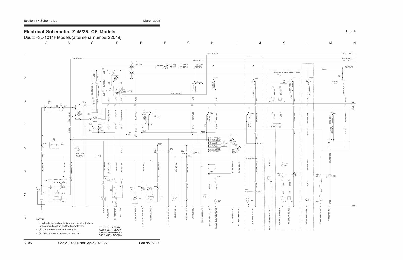
Electrical Schematic, Z-45/25, CE ModelsDeutz F3L-1011F Models (after serial number 22049)
1
2
3
4
5
6
7
8
A B C D E F G H I J K L M N
March 2005Section 6 • Schematics
6 - 35 Genie Z-45/25 and Genie Z-45/25J Part No. 77809
REV A
C1
33
PL
AC
23
TT
SR
WH
HO
RN
RE
LA
Y
LE
VE
LS
EN
SO
R
HO
RN
+
-
RD
P2
0B
AT
RD
TB20
C2
1IG
NW
H
C4
1R
PM
OR
/BK
CR5NO
C4
6H
RN
BK
/RD
CB115A
RD
RD
CB215A
TB41
C4
6H
RN
BK
/RD
TB23
KS1
PLAT
GRD
P1
RD
P3
HORN
TB134
P2
2B
AT
BK
BK-(FS)C9P-1 BKP2
GE
NE
RA
TO
RO
PT
ION
FL
AS
HIN
GB
EA
CO
NS
OP
TIO
N
HO
UR
ME
TE
R
PO
WE
RR
EL
AY
IGN
ITIO
N/S
TA
RT
RE
LA
Y
STA
RT
ER
MO
TO
R
AU
XIL
IAR
YP
UM
P
AU
XIL
IAR
YP
OW
ER
RE
LA
Y
TS2
GROUNDAUX. ON
KEY PWR.BATTERY
TACHOMETER
IGN./FUEL ONENG. FAULT
KEY BYPASS
START INPUT
START RELAY
4
STARTERAUX
PUMP
PR1
C2
7A
UX
RD
PR1NO
C2
8T
TA
RD
/BK
CR1
NO
CR1
R3
3S
TR
BK
TB21
TB25
NO
CR2
8765
109
CR2
TS51
C2
8T
TA
RD
/BK
TB27
RD
TS1RD
TS52
BK
1
2
TB33
3
C2
1IG
NW
H
FB1
C3
3S
TR
BK
C4
5G
EN
GR
/WH
TS47
P24FS WH
C9P-3RD-(FS)
FS1
BR
N
TS54
TS4
BRN
RD
BK
P24FS WH
P26ESTP BK
OIL
TE
MP
ER
AT
UR
EL
ED
C9P-2
REGULATOR
IND.
ALTERNATOR
BAT.+
STA.
BAT.-
EXCT.
FU
EL
SO
LE
NO
ID
TB24
TB26
C2
6T
SR
WH
/RD
C2
5P
SR
WH
/BK
L42OILPRES.
L43OILTEMP.
SW2NC
SW3NO
OIL
PR
ES
SU
RE
SW
ITC
H
OIL
TE
MP
ER
AT
UR
ES
WIT
CH
OIL
PR
ES
SU
RE
LE
D
TB34
TS56
C3
4S
AB
K/W
H
TS6
PR3
CR4NO CR4
PR3NO
HIG
HR
PM
SO
LE
NO
ID
HIG
HID
LE
RE
LA
Y
TIL
TA
LA
RM
P2
2B
AT
BK
GL
OW
PL
UG
OP
TIO
N
WH-(FS)
H1
RD
WH
BR
NB
K
BK
C3
P-9
H2HM
+
_
C41RPM OR/BK
RD
P25FS RD
P26ESTP BK
C4
P-1
C1
P-2
C1
P-1
C2
7A
UX
RD
C7
P-1
C1
P-7
C1
P-8
C2
P-7
GE
NE
RA
TO
R
C1
P-9
C3
5H
SB
K/R
D
C4
1R
PM
OR
/BK
C28TTA RD/BKC28TTA RD/BK
C28TTA RD/BK
C41RPM OR/BK
ENGINESPEED
HIG
HR
PM
LO
WR
PM
FU
NC
TIO
NE
NA
BL
E
C1
B-9
C5
-18
ON
GL
OW
PL
UG
C1
B-8
ON
GL
OW
PL
UG
EN
GIN
ES
TA
RT
EN
GIN
ES
TA
RT
C5
-12
AU
XIL
IAR
YP
UM
P
C1
B-7
C4
5G
EN
GR
/WH
C5
-22
C5
-14
C5
-16
C5
-11
C6
-9
C3
4S
AB
K/W
H
C5
-5
C21IGN WH
C2
1IG
N2
WH
C3
B-9
C5
-2
C5-3
C7
B-4
C5
-24
C2
B-7
B112V DC
D1
C33MF
+
M2
M3
PR2PR2NO
Q3
S8
U1IGNITION/
STARTMODULE
U32
C3
5H
SB
K/R
D
BK
/RD
C6
-34
C2
B-3
WO
RK
LIG
HT
DR
IVE
LIG
HT
LIG
HT
S
L30 L30
L29L29
FUSE 10A (ONLY FOR WORKLIGHTS)
C2
P-5
C2
B-5
C4
3D
LIT
EG
R
C2
P-11
C2
P-1
2C
2P
-10
C2
P-9
PBOX GND
RD
RD
CR23NO
CR23
DR
IVE
LIG
HT
OP
TIO
N
WO
RK
LIG
HT
SO
PT
ION
C6
-38
C6
-39
TS48
RD
RD
C7
B-1
C1B & C1P = GRAYC2B & C2P = BLACKC3B & C3P = GREENC4B & C4P = BROWN
FUSE10A
BK/RD
P20BAT RD
A B
C
FO
OT
SW
ITC
HH
IGH
ON
SU
PR
ES
SIO
ND
IOD
E
U32PLAT.OVERLOAD
4
6
12 8
7
5
AU
XIL
AR
YP
UM
PC
1B
-1
D3
D4
C7
P-2
P2
3B
AT
WH
C7
B-2
D2
D39
D40
1 3
H6 L45
LS18
C1
P-1
2
C2
P-5
C1
32
PL
IB
L/W
H
C1
34
PW
RB
L/R
D
C2
B-5
C1
B-1
2
TB22
C4
B-1
C1
B-2
C23 ALARM RD
L4
NOTE:
1. All switches and contacts are shown with the boomin the stowed position and the keyswitch off.
4
5 Add D40 only if unit has L4 and L48.
CE and Platform Overload Option
5
4

Electrical Schematic, Z-45/25, CE ModelsDeutz F3L-1011F Models (after serial number 22049)
1
2
3
4
5
6
7
8
N M L K J I H G F E D C B A
Part No. 77809 Genie Z-45/25 and Genie Z-45/25J 6 - 36
March 2005 Section 6 • Schematics
REV A
TS7
TS57
WH
C1
7P
RL
GR
C1
8P
RR
GR
/BK
LE
FT
RIG
HT
PL
AT
RO
TA
TE
RIG
HT
PL
AT
FO
RM
RO
TA
TE
LE
FT
P26ESTP BK
C41RPM OR/BK
C28TTA RD/BK
BRN
RD
RD
BK
P24FS WH
WH
-4
BO
OM
RE
TR
AC
T
CR33
PL
AT
FO
RM
RO
TA
TE
RIG
HT
AN
DJIB
BO
OM
DO
WN
PL
AT
FO
RM
RO
TA
TE
LE
FT
AN
DJIB
BO
OM
UP
C6
-19
DE
SC
EN
TA
LA
RM
OP
TIO
N
H3
C2
2-2
C5
-25
C2
3-2
PL
AT
FO
RM
LE
VE
LD
OW
N
PL
AT
FO
RM
LE
VE
LU
P
BO
OM
EX
TE
ND
C2
1-2
C2
0-2
C1
6-2
C1
7-2
C4
4D
AB
K
C1
8JD
GR
/BK
C2
2-1
C2
3-1
C1
7JU
GR
C6
-18
C6
-17
C1
5P
LD
OR
/BK
C1
4P
LU
OR
C2
1-1
C2
0-1
C8
PB
RB
K/W
H
C1
6-1
C1
7-1
C7
PB
EB
K
C6
-15
C6
-14
C6
-8
C6
-7
C6
-20
BK
-5
C6
-13
LS
4-S
EC
ON
DA
RY
BO
OM
UP
DR
IVE
LIM
ITS
WIT
CH
LS
1-P
RIM
AR
YB
OO
ME
XT
EN
DD
RIV
EL
IMIT
SW
ITC
H
LS
2-P
RIM
AR
YB
OO
MU
PD
RIV
EL
IMIT
SW
ITC
H
LS
3-D
RIV
EE
NA
BL
EL
IMIT
SW
ITC
H
SE
CO
ND
AR
YB
OO
MU
P
SE
CO
ND
AR
YB
OO
MS
EL
EC
TR
EL
AY
SE
CO
ND
AR
YB
OO
MD
OW
N
C1
8-2
C1
9-2
PR
IMA
RY
BO
OM
UP
PR
IMA
RY
BO
OM
SE
LE
CT
RE
LA
Y
PR
IMA
RY
BO
OM
DO
WN
TU
RN
TA
BL
ER
OTA
TE
SE
LE
CT
RE
LA
Y
TU
RN
TA
BL
ER
OTA
TE
RIG
HT
TU
RN
TA
BL
ER
OTA
TE
LE
FT
C1
3-2
C1
4-2
C1
2-2
C1
5-2
BK LS3
C6
-10
C6
-11
C1
0-1
WH
-6RD
C11
-3B
K-7
C1
0-2
14
C11
SB
DB
L/B
K
C1
0S
BU
BL
C1
8-1
C1
9-1
LS2
22
21
C1
0-4
WH
-5
BK
-6
13
2
8587a 87
8630
CR37
C4
TR
LW
H
C5
TR
RW
H/B
K
C2
PB
DR
D/B
K
C1
3-1
C1
4-1
C1
2-1
C1
5-1
C1
PB
UR
D
8587a 87
8630
C6
-2
C6
-5
C6
-4
C6
-1
CR32
8587a 87
8630
BR
AK
ER
EL
EA
SE
VA
LV
E
TR
AV
EL
AL
AR
MO
PT
ION
MO
TO
RS
TR
OK
E
ST
EE
RL
EF
T
ST
EE
RR
IGH
T
C2
4-2
C2
5-2
C2
8-2
C2
6-2
DR
IVE
ED
CR
EV
ER
SE
DR
IVE
ED
CF
OR
WA
RD
GR
OU
ND
BR
N
BR
N
BK
RD
C3
7S
TC
BL
/BK
C3
6S
TC
CB
L
C2
4-1
C2
5-1
C2
9M
SR
D/W
H
C3
2B
RK
WH
/RD
C3
2TA
WH
/RD
C2
8-1
C2
6-1 H4
C6
-37
C6
-36
C6
-29
C6
-32
C6
-33
C3
1R
EV
WH
/BK
C3
0F
WD
WH
RD
BK
U4
C5
-20
C5
-21
TB5
C5
TR
RW
H/B
K
RE
TR
AC
T
EX
TE
ND
BO
OM
J3 J1 J1
C1
5P
LD
OR
/BK
RE
TR
AC
T
EX
TE
ND
BO
OM
DO
WN
DO
WN
UP
UP
PL
AT
FR
OM
LE
VE
L
PL
AT
FR
OM
LE
VE
L
C1
4P
LU
OR
C8
PB
RB
K/W
H
C7
PB
EB
K
C2
2L
SB
K
TB18
TB17
C4
B-5
TB14
C4
B-6
TB15
C4
B-2
C4
B-3
TB7
TB8
C3
B-8
C3
B-7
C4
P-5
C4
P-2
C4
P-3
TS59 TS63
C4
P-6
C3
P-8
C3
P-7
DO
WN
UP
BO
OM
SE
CO
ND
AR
Y
C1
6P
DR
EO
R/R
D
C1
2S
BF
BL
/WH
C11
SB
DB
L/B
K
DO
WN
UP
PR
IMA
RY
BO
OM
C3
PB
FR
D/W
H
C1
0S
BU
BL
C2
PB
DR
D/B
K
C1
PB
UR
D
LE
FT
RIG
HT
TU
RN
TA
BL
ER
OTA
TE
LS1
C1
0-3
WH
-6
21
WH
-7
22
LS4
C11
-2
C6
-16
22BK
-4
C4
B-4
TB10
TB12
TB11
C3
B-1
0
C3
B-1
1
C11
-4
21
OR BK
-6
C6
-40
C11
-1
TB3
C3
B-1
2
C3
B-3
C3
B-2
C3
B-1
TB2
TB6
TB1
C3
B-5
14
BK
C2
B-2
C40LSS OR
TS60
U13 JOYSTICK CONTROL CARD
C2
P-2
C4
P-4
CELIFT/DRIVEOPTION
4 3
C3
P-1
0
C3
P-1
1
12
13
TS61 TS62
10
R4
J2
C3
P-1
2
C3
P-2
C3
P-3
C3
P-1
8 7 6
C3
P-5
10
TS9 TS13
6
P2
4F
SW
H
P2
6E
ST
PB
K
CR30NO
3 4
CR27NC
P2
4F
SW
H BR
N
BR
N
OR
YE
L
12
10 9 3
1 2 3 4 5
PW
R
GN
D
OU
T
JC1
SECONDARY BOOMUP/DOWN
P26ESTP BK
BR
N1
2
7 21
GN
D
RD
OR
BK
211 1
543 6 7
PW
R
XO
UT
YO
UT
PRIMARY BOOM UP/DOWNAND TURNTABLE ROTATE
JC2
J1
C4
1R
PM
OR
/BK
J1C
37
ST
CB
L/B
K
C2
9M
SR
D/W
H
C6
TR
FW
H/R
D
C3
6S
TC
CB
L
C3
1R
EV
WH
/BK
C3
2B
RK
WH
/RD
C3
0F
WD
WH
BA
TG
ND
C3
B-6
C1
B-1
0
C1
B-1
1
TB32
C1
B-3
C1
B-6
C1
B-5
C1
B-4
C7
B-3
C3
P-6
C1
P-1
0
C1
P-1
1
18
119 17
C1
P-3
C1
P-6
20
19
C1
P-5
C2
P-3
C1
P-4
C7
P-3
15
16 5
C28TTA RD/BK
RIG
HT
LE
FT
DR
IVE
EN
AB
LE
RK
OU
T
L1
7
WHB
RN
OR
BL
BL
14 5
13 4
GN
D21 3 4 5 6
PW
R
YO
UT
DR
IVE
MO
DE
CD
E3
BL
/RD
CD
E2
BL
/BK
6 7
3
16 8
CD
E1
BL
P24FS WH
P26ESTP BK
DRIVE & STEERING
JC3TS15
15
TS14
3
NOTES:1. ALL LIMIT SWITCHES SHOWNWITH BOOM IN STOWED POSITIONEXCEPT AS NOTED.
SWITCH SHOWN WITH BOOMROTATED PAST EITHER NON-STEERWHEEL.
ROCKER STEER OPTION ONLY.
2
C1B & C1P - GRAYC2B & C2P - BLACKC3B & C3P - GREENC4B & C4P - BROWN

Electrical Schematic, Z-45/25, CE ModelsDeutz F3L-1011F Models (after serial number 22049)
March 2005 Section 6 • Schematics
Ground Control Box Terminal Strip Wiring Diagram, Z-45/25Deutz F3L-1011F Models (before serial number 22050)
March 2005Section 6 • Schematics
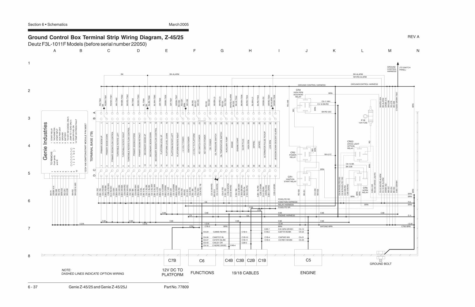
Ground Control Box Terminal Strip Wiring Diagram, Z-45/25Deutz F3L-1011F Models (before serial number 22050)
1
2
3
4
5
6
7
8
A B C D E F G H I J K L M N
March 2005Section 6 • Schematics
6 - 37 Genie Z-45/25 and Genie Z-45/25J Part No. 77809
REV A
DC
PR
IMA
RY
BO
OM
UP
1 2 3 4 5 6 7 8 10
PR
IMA
RY
BO
OM
DO
WN
PR
IMA
RY
BO
OM
FL
OW
CO
NT
RO
L
TU
RN
TA
BL
ER
OTA
TE
LE
FT
TU
RN
TA
BL
ER
OTA
TE
RIG
HT
TU
RN
TA
BL
ER
OTA
TE
FL
OW
CO
NT
RO
L
PR
IMA
RY
BO
OM
EX
TE
ND
PR
IMA
RY
BO
OM
RE
TR
AC
T
SE
CO
ND
AR
YB
OO
MU
P
+1
2V
OLT
PO
WE
R
PL
AT
FO
RM
RO
TA
TE
RIG
HT
PL
AT
FO
RM
RO
TA
TE
LE
FT
PL
AT
FO
RM
LE
VE
LD
OW
N
PL
AT
FO
RM
LE
VE
LU
P
SE
CO
ND
AR
YB
OO
MF
LO
WC
ON
TR
OL
SE
CO
ND
AR
YB
OO
MD
OW
N
2011
15
17
18
14
12
AU
XIL
IAR
YP
UM
P
OIL
TE
MP
ER
AT
UR
ES
WIT
CH
KE
YS
WIT
CH
PO
WE
R
IGN
ITIO
NP
OW
ER
21
25
27
26
23
24
HIG
HR
PM
EN
GIN
ES
TA
RT
BR
AK
E
39
35
38
33
34
32
LO
WR
PM
ALT
ER
NA
TO
RP
UL
SE
PIC
KU
P4
1
44
42
BA
C6
-1R
D
C3
B-1
RD
C6
-2R
D/B
K
C3
B-2
RD
/BK
C3
B-3
RD
/WH
C6
-4W
H
C3
B-4
WH
C6
-5W
H/B
K
C3
B-5
WH
/BK
C6
-6W
H/R
D
C6
-7B
K
C3
B-7
BK
C6
-8B
K/W
H
C3
B-8
BK
/WH
C6
-10
BL
C3
B-1
0B
L
C6
-11
BL
/BK
C3
B-1
1B
L/B
K
C6
-12
BL
/WH
C3
B-1
2B
L/W
H
C6
-14
OR
C6
-15
OR
/BK
C6
-17
GR
C4
B-5
GR
C6
-18
GR
/BK
C4
B-6
GR
/BK
C1
B-1
RD
C7
B-4
RD
C5
-3W
H
C7
B-1
BK
C7
B-2
WH
C1
B-6
WH
/RD
C6
-32
WH
/RD
C1
B-7
BK
C5
-22
BK
/WH
C2
B-3
OR
/BK
C5
-2O
R/B
K
C2
B-6
GR
/BK
RD
-TS
61
RD
/BK
-TS
61
WH
-TS
62
WH
/BK
-TS
62
BK
-TS
63
BK
/WH
-TS
63
BL
-TS
60
BL
/BK
-TS
60
BL
/WH
-TS
60
OR
-TS
59
OR
/BK
-TS
59
GR
-TS
57
GR
/BK
-TS
57
RD
-CB
1
BK
/RD
-TS
54
RD
/WH
-TS
61
WH
/RD
-TS
62
C3
B-6
WH
/RD
C1B
C4B
C5
BATGND BRN
ENGINE HARNESS
FUNCTION HARNESS
WH
-23
B
RD
-27
B
GROUND CONTROL HARNESS
(TO SWITCHPANEL)
E.H.
F.H.
OR
/BK
-IS
2
TE
RM
INA
LB
AS
E(T
B)
1 2 3 4 5 6 7 8 10
11
15
17
18
14
12
20
24
26
27
25
23
21
38
39
34
35
32
33
44
42
41
GROUNDCONTROL HARNESS
GROUNDCONTROLHARNESS
1 2 3 4 5 6 7 8 9 10
1 2 3 4 5 6 7 8 9 10
STA
RT
RE
LA
Y
TA
CH
OM
ET
ER
STA
RT
INP
UT
AU
XP
WR
UN
IT
GR
OU
ND
BA
TT
ER
Y
TO
KE
YS
W(D
IES
EL
ON
LY
)
JU
MP
TO
7(G
AS
ON
LY
)
IGN
OR
FU
EL
ON
TE
MP
OR
PR
ES
SF
AU
LT
13
47
10
92
12
/24
Vo
ltIG
NIT
ON
/STA
RT
MO
DU
LE
P/N
56
05
7
Ge
nie
Ind
ustr
ies
TO
RE
MO
VE
:
Pu
sh
ge
ntly
an
dlif
t
(SP
AR
E)
BK
-R1
OR
/BK
-41
A
BK
-33
B
RD
-27
B
BR
N-I
S5
WH
-R2
RD
-CR
1
C6
-3R
D/W
H
C4
B-2
OR
C4
B-3
OR
/BK
C6
-27
RD
WH
-IS
7
WH
-KS
RD
-TS
51
BK
-33
TS
52
BK
/RD
-R4
OR
/BK
-41
A
WH
-IS
7
RD
-IS
4
OR
/BK
-IS
2
BK
-IS
1
WH
-IS
9
C5
-5B
K
C7B3 BRN
I.S.M. I.S.M. I.S.M. I.S.M.
C6
C4B
C5
C7B
WH
/RD
-AL
AR
M
BK-ALARMBK-ALARMBK
C6
-33
WH
/RD
-AL
AR
M
C5
-19
BK
-AL
AR
M
WH
/RD
-32
A
BK
-AL
AR
M
C6
-34
RD
FB
BK
BK
WH/RD-ALARM
JIB
BO
OM
DO
WN
DE
SC
EN
TA
LA
RM
BR
NB
RN
GROUND BOLT
NOTE:DASHED LINES INDICATE OPTION WIRING
RD
-IS
6
RD
-IS
4
FUNCTIONS ENGINE19/18 CABLES
C5C6 C2B C1BC3BC4B
12V DC TOPLATFORM
C7B
CB
1P
OW
ER
WH
/RD
-L3
-C3BC3B C3B C3B C3B
C2B
C2
B-1
BL
/RD
(SP
AR
E)
BL
/RD
-TS
53
BL
/WH
-L2
-
OIL
PR
ES
SU
RE
SW
ITC
H
CR5HORNRELAY
BR
N
WH-21C
RD
-24
B
C6-13 BK
C6
-9B
K/R
D
BRN
BRNBRN
BR
N
BRN
C3
B-9
BK
/RD
C3B
+1
2V
OLT
TO
PL
AT
FO
RM
22
22
C5
-23
WH
BK-22B
C7B-3
CR4
SOLENOIDRELAY
HIGH RPM
C5-18 BK/RD
BR
N
WH
BR
N
WH
CR1
START RELAYIGNITION
CR2
RELAYPOWER
BK/RD-35C
C16DRE OR/RDC6-16 C4B-4
C1
9JS
VG
R/W
HT
S5
7C
4B
-7G
R/W
H
C43DLITE GR
C4B C4BC4B
C36STCC BLC6-36 C1B-10
C37STC BL/BKC6-37 C1B-11
C30FWD WHC1B-4 C5-21
C31REV WH/BKC1B-5 C5-20
C28TTA RD/BK C5-24C1B-2C29MS RD/WHC6-29 C1B-3
C40LS1 ORC6-40 C2B-2G
LO
WP
LU
GC
1B
-8B
K/W
H
WH
-25
D&
26
D
C1
B-9
BK
/RD
C6
-20
RD
BR
N
BK
/WH
-TS
56
WH
/BK
-L2
-
C5-11 WH
BK
-R5
OR
/RD
-TS
54
OR
/RD
-CR
3
BRN
CR23DRIVE LIGHTOPTIONRELAY
C6
-38
R4
3D
LIT
E1
RD
C6
-39
R4
3D
LIT
E2
RD
BRN
BR
NR
D
P20DLITE RD
C2
B-5
GR
WH
-IS
10
C2
B-4
OR
/RD
BRN
BRN
F1910A FUSE
C5
-14
WH
/RD
C45 GEN GR/WH C5-12C2B-7
RD
-R2
RD
-CB
1
RD
-CB
2C
R2
3R
D
RD
-20
CD
RIV
EL
IGH
TS
WH
-HM
WH
-R2
KE
YS
WIT
CH
PO
WE
R2
32
3
C5
-16
WH
/RD
GR
/BK
-TS
58
BK
-AL
AR
M
RELAY HARNESS
I.S.M.
BRN
WH
-23
B
BK
-33
BB
K-I
S3
BK
-IS
3

Ground Control Box Switch Panel Wiring Diagram, Z-45/25Deutz F3L-1011F Models (before serial number 22050)
1
2
3
4
5
6
7
8
N M L K J I H G F E D C B A
Part No. 77809 Genie Z-45/25 and Genie Z-45/25J 6 - 38
March 2005 Section 6 • Schematics
REV A
NOTE: DASHED LINES INDICATE OPTION WIRES
HO
UR
ME
TE
R
KS
1K
EY
SW
ITC
H
BA
SE
BO
XH
AR
NE
SS
(TO
TE
RM
INA
LS
TR
IP)
BK
/RD
-35
A
RD
-20
B
RD
RD
RD
RD
-20
A
BK
-33
A
RD
RD
RD
RD
RD
RD
RDRD
RDRDRD
RD
RDRD
WH
-21
BR
N
RD
RD
GR
/BK
-18
GR
/BK
-18
A
RDG
R-1
7G
R-1
7A
C1
9JS
VG
R/W
HC
4B
-7G
R/W
H
OR
-14
A
RD
OR
/BK
-15
A
RDRD
BL
/WH
-12
A
BL
/BK
-11
A
RD
BL
-10
A
RD
RD
RD
RD
RD
RDRD
WH
/RD
-6
WH
-4
WH
/BK
-5
WH
/RD
-6A
WH
-4A
WH
/BK
-5A
RD
RD
RDRD RD
RDRD RD
RD
RD
RD
BK
/WH
-8A
BK
-7A
RD
-1A
RD
RD
/WH
-3A
RD
/BK
-2A
RD
BK/WH-8
BK-7
RD
RD
WH-23
WH
-23
A
RD
BK
-22
RD
RD
-27
RD
-27
A
RD
RD
RD
KS
1
TS
59
PL
AT
FO
RM
LE
VE
L
TS
57
PL
AT
FO
RM
RO
TA
TE
CB
2B
RE
AK
ER
CO
NT
RO
LS
,1
5A
CIR
CU
IT
CB
1B
RE
AK
ER
EN
GIN
E,1
5A
CIR
CU
IT
TS
54
FU
NC
TIO
NE
NA
BL
E
TS
52
EN
GIN
ES
TA
RT
TS
60
SE
CO
ND
AR
YB
OO
MU
P/D
OW
N
TS
62
TU
RN
TA
BL
ER
OTA
TE
TS
63
PR
IMA
RY
BO
OM
EX
TE
ND
/RE
TR
AC
T
TS
61
PR
IMA
RY
BO
OM
UP
/DO
WN
R4
CO
NT
RO
LV
AR
IAB
LE
RE
SIS
TE
R
FU
NC
TIO
NS
PE
ED
TS
51
AU
XIL
IAR
YP
OW
ER
P1
ST
OP
SW
ITC
H
STA
CK
ED
CO
NTA
CT
S
L2
OIL
PR
ES
SU
RE
LE
D
BK
/WH
-34
A
RD
RD
RDTS
56
GL
OW
PL
UG
(OP
TIO
N)
3 4NO
3 4NO
3
4NO
3 4NO
1
2
NC
1
2
NC
-+
WH-23WH-23
WH
/RD
-26
A
WH
/BK
-25
LE
D
OIL
TE
MP
L3
RD
-24
A
-+
WH-CR4

Ground Control Box Switch Panel Wiring Diagram, Z-45/25Deutz F3L-1011F Models (before serial number 22050)
March 2005 Section 6 • Schematics

Ground Control Box Terminal Strip Wiring Diagram, Z-45/25Deutz F3L-1011F Models (after serial number 22049)
March 2005Section 6 • Schematics

Ground Control Box Terminal Strip Wiring Diagram, Z-45/25Deutz F3L-1011F Models (after serial number 22049)
1
2
3
4
5
6
7
8
A B C D E F G H I J K L M N
March 2005Section 6 • Schematics
6 - 39 Genie Z-45/25 and Genie Z-45/25J Part No. 77809
REV A
DC
PR
IMA
RY
BO
OM
UP
1 2 3 4 5 6 7 8 10
PR
IMA
RY
BO
OM
DO
WN
PR
IMA
RY
BO
OM
FU
NC
TIO
NC
ON
TR
OL
TU
RN
TA
BL
ER
OTA
TE
RIG
HT
TU
RN
TA
BL
ER
OTA
TE
FU
NC
TIO
NC
TR
L
PR
IMA
RY
BO
OM
EX
TE
ND
PR
IMA
RY
BO
OM
RE
TR
AC
T
SE
CO
ND
AR
YB
OO
MU
P
+1
2V
OLT
PO
WE
R
PL
AT
FO
RM
RO
TA
TE
RIG
HT
PL
AT
FO
RM
RO
TA
TE
LE
FT
PL
AT
FO
RM
LE
VE
LD
OW
N
PL
AT
FO
RM
LE
VE
LU
P
SE
CO
ND
AR
YB
OO
MF
UN
CT
ION
CT
RL
SE
CO
ND
AR
YB
OO
MD
OW
N
2011
15
17
18
14
12
AU
XIL
IAR
YP
UM
P
OIL
PR
ES
SU
RE
SW
ITC
H
KE
YS
WIT
CH
PO
WE
R
IGN
ITIO
NP
OW
ER
21
25
27
26
23
24
HIG
HR
PM
STA
RT
EN
GIN
E
BR
AK
E
39
35
38
33
34
32
LO
WR
PM
ALT
ER
NA
TO
RP
UL
SE
PIC
KU
P4
1
44
42
BA
CR
32
#8
6R
D
C3
B-1
RD
C3
B-2
RD
/BK
C3
B-3
RD
/WH
CR
33
#8
6W
H/B
K
C3
B-5
WH
/BK
C3
B-6
WH
/RD
C6
-7B
K
C3
B-7
BK
C6
-8B
K/W
H
C3
B-8
BK
/WH
CR
37
#8
6B
L
C3
B-1
0B
L
C3
B-1
1B
L/B
K
CR
37
#3
0B
L/W
H
C3
B-1
2B
L/W
H
C6
-14
OR
C6
-15
OR
/BK
C6
-17
GR
C4
B-5
GR
C6
-18
GR
/BK
C4
B-6
GR
/BK
C1
B-1
RD
C7
B-4
RD
C5
-3W
H
C7
B-1
BK
C7
B-2
WH
C1
B-6
WH
/RD
C6
-32
WH
/RD
C1
B-7
BK
C2
B-3
OR
/BK
C5
-2O
R/B
K
C2
B-6
GR
/BK
RD
-TS
61
RD
/BK
-TS
61
WH
/BK
-TS
62
BK
-TS
63
BK
/WH
-TS
63
BL
-TS
60
BL
/BK
-TS
60
BL
/WH
-TS
60
OR
-TS
59
OR
/BK
-TS
59
GR
-TS
57
GR
/BK
-TS
57
RD
-CB
1
BK
/RD
-TS
54
RD
/WH
-TS
61
WH
/RD
-TS
62
CR
33
#3
0W
H/R
D
C1B
C4B
C5
BATGND BRN
ENGINE HARNESS
FUNCTION HARNESS
RD
-27
B
GROUND CONTROL HARNESS
E.H.
F.H.
OR
/BK
-IS
2
TE
RM
INA
LB
AS
E(T
B)
1 2 3 4 5 6 7 8 10
11
15
17
18
14
12
20
24
26
27
25
23
21
38
39
34
35
32
33
44
42
41
GROUNDCONTROLHARNESS
(TO SWITCH PANEL)
1 2 3 4 5 6 7 8 9 10
1 2 3 4 5 6 7 8 9 10
STA
RT
RE
LA
Y
TA
CH
OM
ET
ER
STA
RT
INP
UT
AU
XP
WR
UN
IT
GR
OU
ND
BA
TT
ER
Y
TO
KE
YS
W(D
IES
EL
ON
LY
)
JU
MP
TO
7(G
AS
ON
LY
)
IGN
OR
FU
EL
ON
TE
MP
OR
PR
ES
SF
AU
LT
13
47
10
92
12
/24
Vo
ltIG
NIT
ON
/STA
RT
MO
DU
LE
P/N
56
05
7
Ge
nie
Ind
ustr
ies
TO
RE
MO
VE
:
Pu
sh
ge
ntly
an
dlif
t
BK
-R1
OR
/BK
-41
A
BK
-33
B
RD
-27
B
BR
N-I
S5
WH
-23
B
WH
-R2
RD
-CR
1
CR
32
#3
0R
D/W
H
C4
B-2
OR
C4
B-3
OR
/BK
C6
-27
RD
WH
-KS
RD
-TS
51
BK
-33
TS
52
OR
/BK
-41
A
RD
-IS
4
OR
/BK
-IS
2
BK
-IS
1
WH
-IS
9
C5
-5B
K
C7B3 BRN
I.S.M. I.S.M. I.S.M. I.S.M.
C6
C4B
C5
C7B
WH
/RD
-AL
AR
M
BK-ALARMBK-ALARMBK
C6
-33
WH
/RD
-AL
AR
M
C5
-19
BK
-AL
AR
M
WH
/RD
-32
A
BK
-AL
AR
M
BK
BK
WH/RD-ALARM
BR
NB
RN
GROUND BOLT
NOTE: DASHED LINES INDICATE OPTION WIRES
RD
-IS
6
RD
-IS
4
FUNCTIONS ENGINE19/18 CABLES
C5C6 C2B C1BC3BC4B
12V DC TOPLATFORM
C7B
CB
1P
OW
ER
OIL
TE
MP
ER
AT
UR
ES
WIT
CH
WH
/RD
-L3
-
C3BC3B C3B C3B C3B
C2B
C2
B-1
BL
/RD
(SP
AR
E)
(SP
AR
E)
BL
/RD
-TS
53
BL
/WH
-L2
-
BK
/RD
-R4
CR2
CR1B
RN
WH-21C
RD
-24
B
BRN
C3B
+1
2V
OLT
TO
PL
AT
FO
RM
22
22
C7B-3
HIG
HR
PM
SO
LE
NO
IDR
EL
AY
C5-18 BK/RD
WH
IGN
ITIO
NS
TA
RT
RE
LA
YP
OW
ER
RE
LA
Y
BK/RD-35C
C16DRE OR/RDC6-16 C4B-4
C1
9JS
VG
R/W
HT
S5
7C
4B
-7G
R/W
H
C43DLITE
C4B C4BC4B
C36STCC BLC6-36 C1B-10
C37STC BL/BKC6-37 C1B-11
C30FWD WHC1B-4 C5-21
C31REV WH/BKC1B-5 C5-20
C28TTA RD/BK C5-24C1B-2C29MS RD/WHC6-29 C1B-3
C40LS1 ORC6-40 C2B-2
GL
OW
PL
UG
C5
-22
BK
/WH
C1
B-8
BK
/WH
WH
-25
D&
26
D
C1
B-9
BK
/RD
C6
-20
BK
BK
/WH
-TS
56
WH
/BK
-L2
-
C5-11 WH
BK
-R5
CR4
BRN
R4
3D
LIT
E1
RD
R4
3D
LIT
E2
RD
P20DLITE RD
C2
B-5
GR
WH
-IS
10
C2
B-4
OR
/RD
C5
-14
WH
/RD
C45 GEN GR/WH C5-12C2B-7
RD
-R2
RD
-CB
1
RD
-CB
2C
R2
3R
D
RD
-20
CD
RIV
EL
IGH
TS
WH
-HM
WH
-R2
WH
-IS
7
C5
-16
WH
/RD
RELAY HARNESS
I.S.M.
BRN
WH
-23
BW
H-I
S7
BK
-33
BB
K-I
S3
BK
-IS
3
CR23
F1910A FUSE
C6-13 BK
BK-22B
RD
DR
IVE
LIG
HT
OP
TIO
NR
EL
AY
CR
37
BRN
BRN
BR
N
RD
/WH
3D
RD
1C
C6
-2R
D/B
K
C6
-1R
D
30
85
87
86
87A
30 = COMMON (12V DC IN)87A = NC87 = NO85 = COIL NEGATIVE86 = COIL POSITIVE
C6
-5W
H/B
K
C6
-10
BL
C6
-4W
H
C6
-11
BL
/BK
WH
/RD
6D
WH
/BK
5C
BL
/WH
12
C
BL
10
C
30
30
30
30
30
30
85
85
85
85
85
85
87
8787
87
87
87
86
86
86
86
86
86
87A
87A
87A
87A
87A
87A
30
85
87
86
87A
30
85
87
86
87A
BLBRN
BR
N
13
4K
SP
OW
ER
13
4A
KS
PO
WE
R
RD
KS
1C
5-2
3W
H
C2
-5R
D
C6
-34
RD
BRN GND
GR/BK H6
RD TS52
RD TS51
BK C7-1
BK 22B
BK/WH C1-12
RD H6
C3
2
13
44
55
66
77
81
2
RD
H6
RD
C2
3-1
RD
13
4B
GR
/BK
C2
3-8
GR
/BK
L4
5
GR
/BK
C4
B-1
BRN
C6
-38
C6
-39
CR5HORNRELAY
C3
B-9
BK
/RD
13
4A
13
4
CR32
RELAY
PRIMARYBOOM
CR33
RELAY
TURNTABLEROTATE
CR37SECONDARY
RELAYBOOM
C6
-9B
K/R
D
BR
NC
3
+
H6(CE option only)

Ground Control Box Switch Panel Wiring Diagram, Z-45/25Deutz F3L-1011F Models (after serial number 22049)
1
2
3
4
5
6
7
8
N M L K J I H G F E D C B A
Part No. 77809 Genie Z-45/25 and Genie Z-45/25J 6 - 40
March 2005 Section 6 • Schematics
REV A
P1 RED EMERGENCY STOP BUTTON
KS1 KEY SWITCH
TS51 AUXILIARY POWER TOGGLE SWITCH
TS52 ENGINE START TOGGLE SWITCH
TS54 FUNCTION ENABLE TOGGLE SWITCH
TS56 GLOW PLUG TOGGLE SWITCH (OPTION)
TS57 PLATFORM ROTATE TOGGLE SWITCH
TS59 PLATFORM LEVEL TOGGLE SWITCH
TS63 PRIMARY BOOM EXTEND/RETRACT TOGGLE SWITCH
TS61 PRIMARY BOOM UP/DOWN TOGGLE SWITCH
TS62 TURNTABLE ROTATE TOGGLE SWITCH
LABEL DESCRIPTION
TS60 SECONDARY BOOM UP/DOWN TOGGLE SWITCH
CB1 CIRCUIT BREAKER, ENGINE, 15A
CB2 CIRCUIT BREAKER, CONTROLS, 15A
HM HOUR METER
R4 SPEED LIMITING VARIABLE RESISTOR 20 OHMS
L42 OIL PRESSURE LED
CR1 IGNITION / START RELAY
CR2 IG ITION POWER RELAYN
CR4 HIGH IDLE RELAY
CR5 HORN RELAY
L43 OIL TEMPERATURE LED
HIGH IDLE RELAY
L45 PLATFORM OVERLOAD
HO
UR
ME
TE
R
BA
SE
BO
XH
AR
NE
SS
(TO
TE
RM
INA
LS
TR
IP)
BK
/RD
-35
A
RD
-20
B
RD
RD
C2
3-7
RD
RD
-20
A
BK
-33
A
RD
RD
RD
RD
RD
RD
RD
RD
RD
RD
RD
RDRD
RDRDRD
RDRDRD
RD
RDRD
RDRD
BRN
WH
-21
BR
N
RD
RD
RD
RD
GR
/BK
-18
GR
/BK
-18
A
RD
RD
GR
GR
-17
GR
-17
A
C1
9JS
VG
R/W
HC
4B
-7G
R/W
H
OR
-14
A
RD
OR
/BK
-15
A
RDRD
BL
/WH
-12
A
BL
/BK
-11
A
RD
BL
-10
A
RD
RDRD
RD
RDRDRDRDRD
WH
/RD
-6
WH
-4
WH
/BK
-5
WH
/RD
-6A
WH
-4A
WH
/BK
-5A
RDRD
RDRD
RD
RDRD RD
RD
RD
RD
RD
BK
/WH
-8A
BK
-7A
RD
-1A
RD
RD
/WH
-3A
RD
/BK
-2A
RD
BK/WH-8
BK-7
RD
RD
WH-23WH-23
WH
/RD
-26
A
WH
/BK
-25
WH-23
RD
13
4A
RD
-27
RD
-27
A
WH
TS
59
PL
AT
FO
RM
LE
VE
L
TS
57
PL
AT
FO
RM
RO
TA
TE
CB
2C
IRC
UIT
BR
EA
KE
RC
ON
TR
OL
S1
5A
CB
1C
IRC
UIT
BR
EA
KE
RE
NG
INE
15
A
TS
54
FU
NC
TIO
NE
NA
BL
E
TS
52
STA
RT
EN
GIN
E
TS
60
SE
CO
ND
AR
YB
OO
MU
P/D
OW
N
TS
62
TU
RN
TA
BL
ER
OTA
TE
TS
63
PR
IMA
RY
BO
OM
EX
TE
ND
/R
ET
RA
CT
TS
61
PR
IMA
RY
BO
OM
UP
/DO
WN
L4
3O
ILT
EM
PL
ED
R4
FU
NC
TIO
NS
PE
ED
CO
NT
RO
LV
AR
IAB
LE
RE
SIS
TE
R
TS
51
AU
XIL
IAR
YP
OW
ER
P1
EM
ER
GE
NC
YS
TO
PS
WIT
CH
L4
2O
ILP
RE
SS
UR
EL
ED
RD
RD
RD
RD
1
2
NC
1
2
NC
-+
RD
-24
A
TS
56
GL
OW
PL
UG
(OP
TIO
N)
-+
BK
/WH
-34
A
RD
WH-CR4
BK-22A
WH
-23
A
GR
/BK
H6
RD
C2
3-6
RD
L4
5P
LA
TF
OR
MO
VE
RL
OA
DL
ED
(CE
mo
de
ls)
-+
KS
1

Ground Control Box Switch Panel Wiring Diagram, Z-45/25Deutz F3L-1011F Models (after serial number 22049)
March 2005 Section 6 • Schematics

Ground Control Box Terminal Strip Wiring Diagram, Z-45/25, CE ModelsDeutz F3L-1011F Models (after serial number 22049)
March 2005Section 6 • Schematics

Ground Control Box Terminal Strip Wiring Diagram, Z-45/25, CE ModelsDeutz F3L-1011F Models (after serial number 22049)
1
2
3
4
5
6
7
8
A B C D E F G H I J K L M N
March 2005Section 6 • Schematics
6 - 41 Genie Z-45/25 and Genie Z-45/25J Part No. 77809
REV A
DC
PR
IMA
RY
BO
OM
UP
1 2 3 4 5 6 7 8 10
PR
IMA
RY
BO
OM
DO
WN
PR
IMA
RY
BO
OM
FU
NC
TIO
NC
ON
TR
OL
TU
RN
TA
BL
ER
OTA
TE
RIG
HT
TU
RN
TA
BL
ER
OTA
TE
FU
NC
TIO
NC
TR
L
PR
IMA
RY
BO
OM
EX
TE
ND
PR
IMA
RY
BO
OM
RE
TR
AC
T
SE
CO
ND
AR
YB
OO
MU
P
+1
2V
OLT
PO
WE
R
PL
AT
FO
RM
RO
TA
TE
RIG
HT
PL
AT
FO
RM
RO
TA
TE
LE
FT
PL
AT
FO
RM
LE
VE
LD
OW
N
PL
AT
FO
RM
LE
VE
LU
P
SE
CO
ND
AR
YB
OO
MF
UN
CT
ION
CT
RL
SE
CO
ND
AR
YB
OO
MD
OW
N
2011
15
17
18
14
12
AU
XIL
IAR
YP
UM
P
OIL
PR
ES
SU
RE
SW
ITC
H
KE
YS
WIT
CH
PO
WE
R
IGN
ITIO
NP
OW
ER
21
25
27
26
23
24
HIG
HR
PM
STA
RT
EN
GIN
E
BR
AK
E
39
35
38
33
34
32
LO
WR
PM
ALT
ER
NA
TO
RP
UL
SE
PIC
KU
P4
1
44
42
BA
CR
32
#8
6R
D
C3
B-1
RD
C3
B-2
RD
/BK
C3
B-3
RD
/WH
CR
33
#8
6W
H/B
K
C3
B-5
WH
/BK
C3
B-6
WH
/RD
C6
-7B
K
C3
B-7
BK
C6
-8B
K/W
H
C3
B-8
BK
/WH
CR
37
#8
6B
L
C3
B-1
0B
L
C3
B-1
1B
L/B
K
CR
37
#3
0B
L/W
H
C3
B-1
2B
L/W
H
C6
-14
OR
C6
-15
OR
/BK
C6
-17
GR
C4
B-5
GR
C6
-18
GR
/BK
C4
B-6
GR
/BK
C1
B-1
RD
C7
B-4
RD
C5
-3W
H
C7
B-1
BK
C7
B-2
WH
C1
B-6
WH
/RD
C6
-32
WH
/RD
C1
B-7
BK
C2
B-3
OR
/BK
C5
-2O
R/B
K
C2
B-6
GR
/BK
RD
-TS
61
RD
/BK
-TS
61
WH
/BK
-TS
62
BK
-TS
63
BK
/WH
-TS
63
BL
-TS
60
BL
/BK
-TS
60
BL
/WH
-TS
60
OR
-TS
59
OR
/BK
-TS
59
GR
-TS
57
GR
/BK
-TS
57
RD
-CB
1
BK
/RD
-TS
54
RD
/WH
-TS
61
WH
/RD
-TS
62
CR
33
#3
0W
H/R
D
C1B
C4B
C5
BATGND BRN
ENGINE HARNESS
FUNCTION HARNESS
RD
-27
B
GROUND CONTROL HARNESS
E.H.
F.H.
OR
/BK
-IS
2
TE
RM
INA
LB
AS
E(T
B)
1 2 3 4 5 6 7 8 10
11
15
17
18
14
12
20
24
26
27
25
23
21
38
39
34
35
32
33
44
42
41
GROUNDCONTROLHARNESS
(TO SWITCH PANEL)
1 2 3 4 5 6 7 8 9 10
1 2 3 4 5 6 7 8 9 10
STA
RT
RE
LA
Y
TA
CH
OM
ET
ER
STA
RT
INP
UT
AU
XP
WR
UN
IT
GR
OU
ND
BA
TT
ER
Y
TO
KE
YS
W(D
IES
EL
ON
LY
)
JU
MP
TO
7(G
AS
ON
LY
)
IGN
OR
FU
EL
ON
TE
MP
OR
PR
ES
SF
AU
LT
13
47
10
92
12
/24
Vo
ltIG
NIT
ON
/STA
RT
MO
DU
LE
P/N
56
05
7
Ge
nie
Ind
ustr
ies
TO
RE
MO
VE
:
Pu
sh
ge
ntly
an
dlif
t
BK
-R1
OR
/BK
-41
A
BK
-33
B
RD
-27
B
BR
N-I
S5
WH
-23
B
WH
-R2
RD
-CR
1
CR
32
#3
0R
D/W
H
C4
B-2
OR
C4
B-3
OR
/BK
C6
-27
RD
WH
-KS
RD
-TS
51
BK
-33
TS
52
OR
/BK
-41
A
RD
-IS
4
OR
/BK
-IS
2
BK
-IS
1
WH
-IS
9
C5
-5B
K
C7B3 BRN
I.S.M. I.S.M. I.S.M. I.S.M.
C6
C4B
C5
C7B
WH
/RD
-AL
AR
M
BK-ALARMBK-ALARMBK
C6
-33
WH
/RD
-AL
AR
M
C5
-19
BK
-AL
AR
M
WH
/RD
-32
A
BK
-AL
AR
M
BK
BK
WH/RD-ALARM
BR
NB
RN
GROUND BOLT
NOTE: DASHED LINES INDICATE OPTION WIRES
RD
-IS
6
RD
-IS
4
FUNCTIONS ENGINE19/18 CABLES
C5C6 C2B C1BC3BC4B
12V DC TOPLATFORM
C7B
CB
1P
OW
ER
OIL
TE
MP
ER
AT
UR
ES
WIT
CH
WH
/RD
-L3
-
C3BC3B C3B C3B C3B
C2B
C2
B-1
BL
/RD
(SP
AR
E)
(SP
AR
E)
BL
/RD
-TS
53
BL
/WH
-L2
-
BK
/RD
-R4
CR2
CR1B
RN
WH-21C
RD
-24
B
BRN
C3B
+1
2V
OLT
TO
PL
AT
FO
RM
22
22
C7B-3
HIG
HR
PM
SO
LE
NO
IDR
EL
AY
C5-18 BK/RD
WH
IGN
ITIO
NS
TA
RT
RE
LA
YP
OW
ER
RE
LA
Y
BK/RD-35C
C16DRE OR/RDC6-16 C4B-4
C1
9JS
VG
R/W
HT
S5
7C
4B
-7G
R/W
H
C43DLITE
C4B C4BC4B
C36STCC BLC6-36 C1B-10
C37STC BL/BKC6-37 C1B-11
C30FWD WHC1B-4 C5-21
C31REV WH/BKC1B-5 C5-20
C28TTA RD/BK C5-24C1B-2C29MS RD/WHC6-29 C1B-3
C40LS1 ORC6-40 C2B-2
GL
OW
PL
UG
C5
-22
BK
/WH
C1
B-8
BK
/WH
WH
-25
D&
26
D
C1
B-9
BK
/RD
C6
-20
BK
BK
/WH
-TS
56
WH
/BK
-L2
-
C5-11 WH
BK
-R5
CR4
BRN
R4
3D
LIT
E1
RD
R4
3D
LIT
E2
RD
P20DLITE RD
C2
B-5
GR
WH
-IS
10
C2
B-4
OR
/RD
C5
-14
WH
/RD
C45 GEN GR/WH C5-12C2B-7
RD
-R2
RD
-CB
1
RD
-CB
2C
R2
3R
D
RD
-20
CD
RIV
EL
IGH
TS
WH
-HM
WH
-R2
WH
-IS
7
C5
-16
WH
/RD
RELAY HARNESS
I.S.M.
BRN
WH
-23
BW
H-I
S7
BK
-33
BB
K-I
S3
BK
-IS
3
CR23
F1910A FUSE
C6-13 BK
BK-22B
RD
DR
IVE
LIG
HT
OP
TIO
NR
EL
AY
CR
37
BRN
BRN
BR
N
RD
/WH
3D
RD
1C
C6
-2R
D/B
K
C6
-1R
D
30
85
87
86
87A
30 = COMMON (12V DC IN)87A = NC87 = NO85 = COIL NEGATIVE86 = COIL POSITIVE
C6
-5W
H/B
K
C6
-10
BL
C6
-4W
H
C6
-11
BL
/BK
WH
/RD
6D
WH
/BK
5C
BL
/WH
12
C
BL
10
C
30
30
30
30
30
30
85
85
85
85
85
85
87
8787
87
87
87
86
86
86
86
86
86
87A
87A
87A
87A
87A
87A
30
85
87
86
87A
30
85
87
86
87A
BLBRN
BR
N
13
4K
SP
OW
ER
13
4A
KS
PO
WE
R
RD
KS
1C
5-2
3W
H
C2
-5R
D
C6
-34
RD
BRN GND
GR/BK H6
RD TS52
RD TS51
BK C7-1
BK 22B
BK/WH C1-12
RD H6
U33PLATFORMOVERLOAD
MODULE
C3
2
13
45
67
81
2
RD
H6
H6
RD
C2
3-1
RD
13
4B
GR
/BK
C2
3-8
GR
/BK
L4
5
GR
/BK
C4
B-1
BRN
C6
-38
C6
-39
CR5HORNRELAY
C3
B-9
BK
/RD
13
4A
13
4
CR32
RELAY
PRIMARYBOOM
CR33
RELAY
TURNTABLEROTATE
CR37SECONDARY
RELAYBOOM
C6
-9B
K/R
D
BR
NC
3
+

Ground Control Box Switch Panel Wiring Diagram, Z-45/25, CE ModelsDeutz F3L-1011F Models (after serial number 22049)
1
2
3
4
5
6
7
8
N M L K J I H G F E D C B A
Part No. 77809 Genie Z-45/25 and Genie Z-45/25J 6 - 42
March 2005 Section 6 • Schematics
REV A
P1 RED EMERGENCY STOP BUTTON
KS1 KEY SWITCH
TS51 AUXILIARY POWER TOGGLE SWITCH
TS52 ENGINE START TOGGLE SWITCH
TS54 FUNCTION ENABLE TOGGLE SWITCH
TS56 GLOW PLUG TOGGLE SWITCH (OPTION)
TS57 PLATFORM ROTATE TOGGLE SWITCH
TS59 PLATFORM LEVEL TOGGLE SWITCH
TS63 PRIMARY BOOM EXTEND/RETRACT TOGGLE SWITCH
TS61 PRIMARY BOOM UP/DOWN TOGGLE SWITCH
TS62 TURNTABLE ROTATE TOGGLE SWITCH
LABEL DESCRIPTION
TS60 SECONDARY BOOM UP/DOWN TOGGLE SWITCH
CB1 CIRCUIT BREAKER, ENGINE, 15A
CB2 CIRCUIT BREAKER, CONTROLS, 15A
HM HOUR METER
R4 SPEED LIMITING VARIABLE RESISTOR 20 OHMS
L42 OIL PRESSURE LED
CR1 IGNITION / START RELAY
CR2 IG ITION POWER RELAYN
CR4 HIGH IDLE RELAY
CR5 HORN RELAY
L43 OIL TEMPERATURE LED
HIGH IDLE RELAY
L45 PLATFORM OVERLOAD
HO
UR
ME
TE
R
BA
SE
BO
XH
AR
NE
SS
(TO
TE
RM
INA
LS
TR
IP)
BK
/RD
-35
A
RD
-20
B
RD
RD
C2
3-7
RD
RD
-20
A
BK
-33
A
RD
RD
RD
RD
RD
RD
RD
RD
RD
RD
RD
RDRD
RDRDRD
RDRDRD
RD
RDRD
RDRD
BRN
WH
-21
BR
N
RD
RD
RD
RD
GR
/BK
-18
GR
/BK
-18
A
RD
RD
GR
GR
-17
GR
-17
A
C1
9JS
VG
R/W
HC
4B
-7G
R/W
H
OR
-14
A
RD
OR
/BK
-15
A
RDRD
BL
/WH
-12
A
BL
/BK
-11
A
RD
BL
-10
A
RD
RDRD
RD
RDRDRDRDRD
WH
/RD
-6
WH
-4
WH
/BK
-5
WH
/RD
-6A
WH
-4A
WH
/BK
-5A
RDRD
RDRD
RD
RDRD RD
RD
RD
RD
RD
BK
/WH
-8A
BK
-7A
RD
-1A
RD
RD
/WH
-3A
RD
/BK
-2A
RD
BK/WH-8
BK-7
RD
RD
WH-23WH-23
WH
/RD
-26
A
WH
/BK
-25
WH-23
RD
13
4A
RD
-27
RD
-27
A
WH
TS
59
PL
AT
FO
RM
LE
VE
L
TS
57
PL
AT
FO
RM
RO
TA
TE
CB
2C
IRC
UIT
BR
EA
KE
RC
ON
TR
OL
S1
5A
CB
1C
IRC
UIT
BR
EA
KE
RE
NG
INE
15
A
TS
54
FU
NC
TIO
NE
NA
BL
E
TS
52
STA
RT
EN
GIN
E
TS
60
SE
CO
ND
AR
YB
OO
MU
P/D
OW
N
TS
62
TU
RN
TA
BL
ER
OTA
TE
TS
63
PR
IMA
RY
BO
OM
EX
TE
ND
/R
ET
RA
CT
TS
61
PR
IMA
RY
BO
OM
UP
/DO
WN
L4
3O
ILT
EM
PL
ED
R4
FU
NC
TIO
NS
PE
ED
CO
NT
RO
LV
AR
IAB
LE
RE
SIS
TE
R
TS
51
AU
XIL
IAR
YP
OW
ER
P1
EM
ER
GE
NC
YS
TO
PS
WIT
CH
L4
2O
ILP
RE
SS
UR
EL
ED
RD
RD
RD
RD
1
2
NC
1
2
NC
-+
RD
-24
A
TS
56
GL
OW
PL
UG
(OP
TIO
N)
-+
BK
/WH
-34
A
RD
WH-CR4
BK-22A
WH
-23
A
GR
/BK
H6
RD
C2
3-6
RD
L4
5P
LA
TF
OR
MO
VE
RL
OA
DL
ED
(CE
mo
de
ls)
-+
KS
1

Ground Control Box Switch Panel Wiring Diagram, Z-45/25, CE ModelsDeutz F3L-1011F Models (after serial number 22049)
March 2005 Section 6 • Schematics

Platform Control Box Wiring Diagram, Z-45/25Deutz F3L-1011F Models (before serial number 22050)
March 2005Section 6 • Schematics

Platform Control Box Wiring Diagram, Z-45/25Deutz F3L-1011F Models (before serial number 22050)
1
2
3
4
5
6
7
8
A B C D E F G H I J K L M N
March 2005Section 6 • Schematics
6 - 43 Genie Z-45/25 and Genie Z-45/25J Part No. 77809
REV A
RE
D/B
LK
-28
RE
D-T
ILTR
ED
-TILT
BR
NB
RN
C3P
F.S.
C7P
C3P
C7PBATGRN C7P-3
C1P
PLATFORM CONTROL HARNESS(TO SWITCH PANEL)
H1TILT
ALARM12V DC BATTERY
C1
P(G
Y)
19/18 CONTROL CABLE
C7P C9
FOOT SWITCH
JIB OPT.
9
1
J1
JC
3-3
OR
DR
EA
BL
/WH
JC
3-2
BR
N
DR
EB
BL
/BK
C1
3L
ED
BL
/RD
C2
9M
SR
D/W
H
JC
2-5
BK
JC
1-5
YE
L
JC
2-3
OR
JC
3-4
BL
*
JC
2-2
BR
N
JC
3-5
WH
JC
1-3
OR
JC
2-4
RD
JC
1-2
BR
N
J2
1
11
1
P2
4F
SW
H
P2
4F
SW
H
P2
6E
ST
PB
K
J3
3
C2
P(B
K)
C3
P(G
R)
C4
P(B
R)
C28TTA RD/BK C1P-2
BR
N
C2
9M
SR
D/W
HC
1P
-3
C4
TR
LW
HC
3P
-4
C3
2B
RK
WH
/RD
C1
P-6
C5
TR
RW
H/B
KC
3P
-5
C3
6S
TC
CB
KC
1P
-10
C3
PB
FR
D/W
HC
3P
-3
C3
7S
TC
BL
/BK
C1
P-1
1
C2
PB
DR
D/B
KC
3P
-2
C3
1R
EV
WH
/BK
C1
P-5
C1
PB
UR
DC
3P
-1
C3
0F
WD
WH
C1
P-4
C4
1R
PM
OR
/BK
C2
P-3
C1
2S
BF
BL
/WH
C3
P-1
2
C4
0L
SS
OR
C2
P-2
C11
SB
DB
L/B
KC
3P
-11
C1
6D
RE
OR
/RD
C4
P-4
C1
0S
BU
BL
C3
P-1
0
C6
TR
FW
H/R
DC
3P
-6
C2
8T
TA
RD
/BK
C1
P-2
C2P
C2
7A
UX
RD
C1
P-1
C3
3S
TR
BK
C1
P-7
C3
5H
SB
K/R
DC
1P
-9
C3
4S
AB
K/W
HC
1P
-8
C4P
C4
5G
EN
GR
/WH
C2
P-7
P2
4F
SW
HC
9-2
P2
5F
SR
DC
9-3
P2
6B
AT
BK
C9
-1
C7
PB
EB
KC
3P
-7
C8
PB
RB
K/W
HC
3P
-8
C9
HR
NB
K/R
DC
3P
-9
C1
4P
LU
OR
C4
P-2
C1
5P
LD
OR
/BK
C4
P-3
P2
2B
AT
BK
C7
P-1
P2
3S
WB
AT
WH
C7
P-2
* NOTE:
WIRE CONNECTS TOJC3-6 FOR STEER ROCKERSWITCH OPTION.
U13ALC-500
CR30 CR27
P2
4F
SW
HC
9P
-2
C4
0L
SS
OR
C2
P-2
C3
2B
RK
WH
/RD
C1
P-6
WH/RD C1P-6
C3
2B
RK
WH
/RD
J2
-19
C4
0L
SS
OR
J2
-4
CE LIFT/DRIVE OPTION R2
4F
SW
HC
9P
-2
CW
LIT
ER
DC
2P
-11
CW
LIT
ER
DC
2P
-12
CD
LIT
EG
RC
2P
-5
WLITE BRN C2P-10
WLITE BRN C2P-9
BRN
BRNBRN
BR
N

Platform Control Box Switch Panel Wiring Diagram, Z-45/25Deutz F3L-1011F Models (before serial number 22050)
1
2
3
4
5
6
7
8
N M L K J I H G F E D C B A
Part No. 77809 Genie Z-45/25 and Genie Z-45/25J 6 - 44
March 2005 Section 6 • Schematics
REV A
P2EMERGENCY
STOP
TS4HIGH/LOW
RPMTS2
START
TS15DRIVE ENABLE
L1
TS14HIGH/LOW(2WD/4WD)
TS13PRIMARY BOOM
EXTEND/RETRACT
TS7PLATFORM
ROTATETS9
PLATFORMLEVEL
P3HORN
TS1AUXILIARY
POWER
C9
HR
NB
K/R
DC
3P
-9
C1
4P
LU
OR
C4
P-2
C1
5P
LD
OR
/BK
C4
P-3
C1
8P
RR
GR
/BK
C4
P-6
C1
9JS
VG
R/W
HC
4P
-7
C1
7P
RL
GR
C4
P-5
C2
7A
UX
RD
C1
P-1
P2
5F
SR
DC
9-3
C3
3S
TR
BK
C1
P-7
P2
3B
AT
WH
C7
P-2
P2
6B
AT
BK
C9
P-1
P2
6B
AT
BK
-LO
AD
P2
2B
AT
BK
C7
P-1
RD
RD
WH
RD
WH-24
RD RD
TS47GENERATOR
(OPTION)
C8
PB
RB
K/W
HC
3P
-8
BL
/RD
-DE
3J1
-16
C4
5G
EN
GR
/WH
C2
P-7
RD
BL
-DE
1J1
-6
GR/WH
RD
C7
PB
EB
KC
3P
-7
C2
9M
SR
D/W
HJ1
-8
C3
4S
AB
K/W
HC
1P
-8
TS6GLOW PLUG
(OPTION)
WHWH
RD
NOTE: DASHED LINES INDICATE OPTION WIRES
RD
-TIL
T
C3
5H
SB
K/R
DC
1P
-9
12 NC
1
2
NC
BL
/BK
-DE
2J1
-7
4
2
1
3
5
6
7O
RJ1
-13
BR
NJ1
-14
WH
J1
-4
BL
J1
-5(R
OC
KE
RS
WIT
CH
OP
TIO
NO
NLY
)
OR
J1
-9
BR
NJ1
-10
YE
LJ1
-3
OR
J1
-11
BR
NJ1
-12
BK
J1
-2
RD
J1
-1
JC3DRIVE
FORWARD/REVERSE& STEER
LEFT/RIGHT
JC1SECONDARY BOOM
UP/DOWN
JC2PRIMARY BOOM UP/DOWN
& TURNTABLE ROTATELEFT/RIGHT
P2
4F
SW
HC
9-2
RD
BK
BK
BK
BK
BK
BK
34 NO
PLATFORMCONTROLHARNESS
(TO CONTROL BOX)
BL
J1
-5
+
TS48DRIVE LIGHTS/WORK LIGHTS
(OPTION)
RD
RD
PD
LIT
ER
D
CW
LIT
ER
DC
2P
-11
CW
LIT
ER
DC
2P
-12
F18
FUSE 10A
CD
LIT
EG
RC
2P
-5
2
1
3
5
4
6
7
2
1
3
5
4
6
7
GE
NE
RA
TO
RO
PT
ION

Platform Control Box Switch Panel Wiring Diagram, Z-45/25Deutz F3L-1011F Models (before serial number 22050)
March 2005 Section 6 • Schematics

Platform Control Box Wiring Diagram, Z-45/25Deutz F3L-1011F Models (after serial number 22049)
March 2005Section 6 • Schematics

Platform Control Box Wiring Diagram, Z-45/25Deutz F3L-1011F Models (after serial number 22049)
1
2
3
4
5
6
7
8
A B C D E F G H I J K L M N
March 2005Section 6 • Schematics
6 - 45 Genie Z-45/25 and Genie Z-45/25J Part No. 77809
REV A
TILTALALRM
RE
D/B
LK
-28
RE
D-T
ILT
RE
D-T
ILT
C2
P-5
BR
NB
RN
C3P
F.S.
C7P
C3P
C7PBATGRN C7P-3
C1P
PLATFORM CONTROLHARNESS
(TO SWITCH PANEL)
H1
12V DC BATTERYSUPPLY
C1
P(G
Y)
19/18 CONTROL CABLE
C7P C9
FOOT SWITCH
JIBBOOM
LS18(CE ONLY) OPTION
9
1
J1
JC
3-3
OR
DR
EA
BL
/WH
JC
3-2
BR
N
DR
EB
BL
/BK
C1
3L
ED
BL
/RD
C2
9M
SR
D/W
H
JC
2-5
BK
JC
1-5
YE
L
JC
2-3
OR
JC
3-4
BL
*
JC
2-2
BR
N
JC
3-5
WH
JC
1-3
OR
JC
2-4
RD
JC
1-2
BR
N
J2
1
11
1
P2
4F
SW
H
P24FS WH
P2
6E
ST
PB
K
J3
3
C2
P(B
K)
C3
P(G
R)
C4
P(B
R)
C28TTA RD/BK C1P-2
BR
N
C2
9M
SR
D/W
HC
1P
-3
C3
2B
RK
WH
/RD
C1
P-6
C5
TR
RW
H/B
KC
3P
-5
C3
6S
TC
CB
KC
1P
-10
C3
PB
FR
D/W
HC
3P
-3
C3
7S
TC
BL
/BK
C1
P-1
1
C2
PB
DR
D/B
KC
3P
-2
C3
1R
EV
WH
/BK
C1
P-5
C1
PB
UR
DC
3P
-1
C3
0F
WD
WH
C1
P-4
C4
1R
PM
OR
/BK
C2
P-3
C1
2S
BF
BL
/WH
C3
P-1
2
C4
0L
SS
OR
C2
P-2
C11
SB
DB
L/B
KC
3P
-11
C1
6D
RE
OR
/RD
C4
P-4
C1
0S
BU
BL
C3
P-1
0
C6
TR
FW
H/R
DC
3P
-6
C2
8T
TA
RD
/BK
H1
C2P
C2
7A
UX
RD
C1
P-1
C3
3S
TR
BK
C1
P-7
C3
5H
SB
K/R
DC
1P
-9
C3
4S
AB
K/W
HC
1P
-8
C4P
C4
5G
EN
GR
/WH
C2
P-7
P2
4F
SW
HC
9-2
P2
5F
SR
DC
9-3
P2
6B
AT
BK
C9
-1
C7
PB
EB
KC
3P
-7
C8
PB
RB
K/W
HC
3P
-8
C9
HR
NB
K/R
DC
3P
-9
C1
4P
LU
OR
C4
P-2
C1
5P
LD
OR
/BK
C4
P-3
P2
2B
AT
BK
C7
P-1
P2
3S
WB
AT
WH
C7
P-2
* NOTE: WIRE CONNECTS TO JC3-6 FOR STEER ROCKER SWITCH OPTION.
U13ALC-500
CR30 CR27
P2
4F
SW
HC
9P
-2
C4
0L
SS
OR
C2
P-2
C3
2B
RK
WH
/RD
C1
P-6
C3
2B
RK
WH
/RD
J2
-19
C4
0L
SS
OR
J2
-4
CE LIFT/DRIVE OPTION
R2
4F
SW
HC
9P
-2
CW
LIT
ER
DC
2P
-11
CW
LIT
ER
DC
2P
-12
CD
LIT
EG
R
WLITE BRN C2P-10
WLITE BRN C2P-9
BRN
BRNBRN
BR
N
RD LS CABLE
Y
Y
BK
LS
CA
BL
EC
1P
-12
GR
/BK
-L4
GR
/BK
C4
P-1
H1
J3
J2
J1
U13
C1P - C4P
C7P
ALC-500 CONTROL BOARD
CONTROL BOARD POWER CONNECTOR
CONTROL BOARD OUTPUT CONNECTOR
CONTROL BOARD INPUT CONNECTOR
TILT ALARM
12V DC PLATFORM POWER CONNECTOR
48 PIN CONNECTOR BLOCK
DESCRIPTIONITEM
FOOT SWITCH CONNECTORC9
CR27 CONTROL RELAY (CE OPTION)
CR30 CONTROL RELAY (CE OPTION)
LS18 LOAD SENSE LIMIT SWITCH
RD
-P2
RD
-H1
C1
33
PL
AG
R/B
KC
4P
-1
RE
DL
S1
8
1
CE Models: CR27 and CR30 replaces white wire between TS1 and TS71
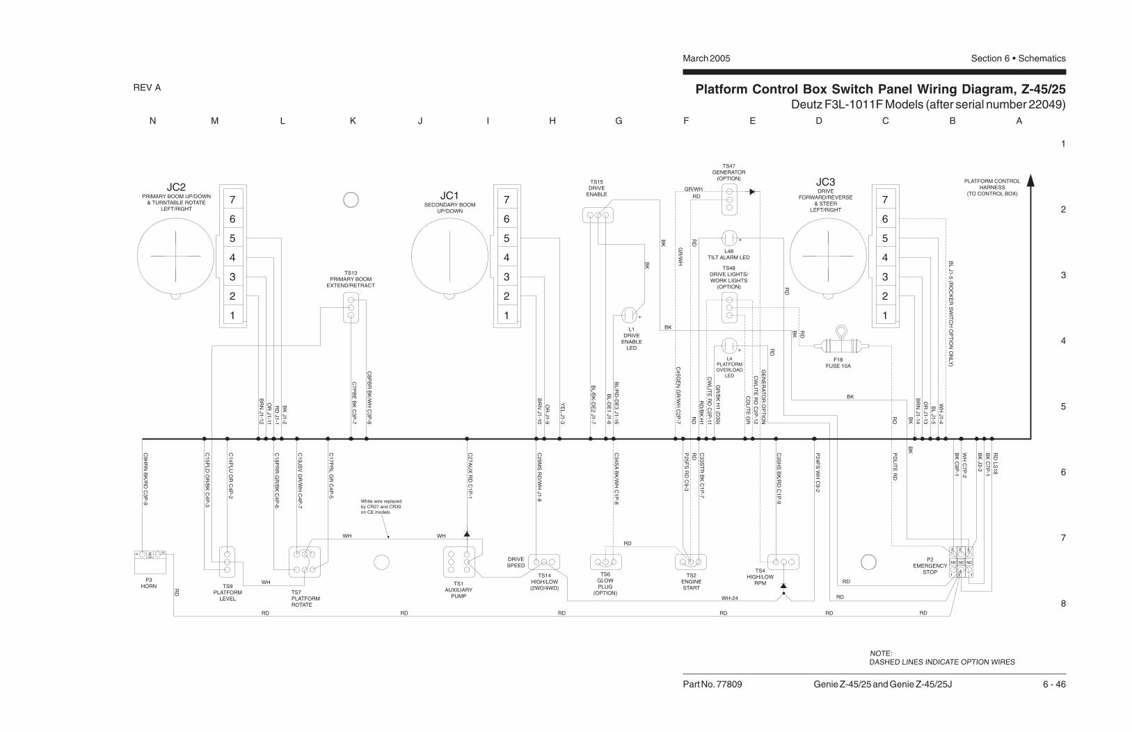
Platform Control Box Switch Panel Wiring Diagram, Z-45/25Deutz F3L-1011F Models (after serial number 22049)
1
2
3
4
5
6
7
8
N M L K J I H G F E D C B A
Part No. 77809 Genie Z-45/25 and Genie Z-45/25J 6 - 46
March 2005 Section 6 • Schematics
REV A
P2EMERGENCY
STOPTS4HIGH/LOW
RPM
TS2ENGINESTART
TS15DRIVE
ENABLE
L1DRIVE
ENABLELED
DRIVESPEED
TS14HIGH/LOW(2WD/4WD)
TS13PRIMARY BOOM
EXTEND/RETRACT
TS7PLATFORMROTATE
TS9PLATFORM
LEVEL
P3HORN TS1
AUXILIARYPUMP
C9
HR
NB
K/R
DC
3P
-9
RD
C1
4P
LU
OR
C4
P-2
C1
5P
LD
OR
/BK
C4
P-3
C1
8P
RR
GR
/BK
C4
P-6
C1
9JS
VG
R/W
HC
4P
-7
C1
7P
RL
GR
C4
P-5
C2
7A
UX
RD
C1
P-1
P2
5F
SR
DC
9-3
C3
3S
TR
BK
C1
P-7
BK
C9
P-1
WH
C7
P-2
RD
WH
RD RD
WH-24
RD RD RD
TS47GENERATOR
(OPTION)
C8
PB
RB
K/W
HC
3P
-8
BL
/RD
-DE
3J1
-16
C4
5G
EN
GR
/WH
C2
P-7
RD
BL
-DE
1J1
-6
GR/WH
RD
C7
PB
EB
KC
3P
-7
GR
/WH
RD
C2
9M
SR
D/W
HJ1
-8
TS6GLOWPLUG
(OPTION)
C3
4S
AB
K/W
HC
1P
-8
WHWH
RD
NOTE:DASHED LINES INDICATE OPTION WIRES
C3
5H
SB
K/R
DC
1P
-9
2
1
NC
2
1
NC
BL
/BK
-DE
2J1
-7
4
2
1
3
5
6
7O
RJ1
-13
BR
NJ1
-14
WH
J1
-4
BL
J1
-5(R
OC
KE
RS
WIT
CH
OP
TIO
NO
NLY
)
OR
J1
-9
BR
NJ1
-10
YE
LJ1
-3
OR
J1
-11
BR
NJ1
-12
BK
J1
-2
RD
J1
-1
JC3DRIVE
FORWARD/REVERSE& STEER
LEFT/RIGHT
JC1SECONDARY BOOM
UP/DOWN
P2
4F
SW
HC
9-2
RD
BK
BK
BK
BK
BK
BK
34 NO
PLATFORM CONTROLHARNESS
(TO CONTROL BOX)B
LJ1
-5
+
TS48DRIVE LIGHTS/WORK LIGHTS
(OPTION)
RD
RD
PD
LIT
ER
D
CW
LIT
ER
DC
2P
-11
CW
LIT
ER
DC
2P
-12
F18FUSE 10A
CD
LIT
EG
R
2
1
3
5
4
6
7
2
1
3
5
4
6
7JC2
PRIMARY BOOM UP/DOWN& TURNTABLE ROTATE
LEFT/RIGHT
GE
NE
RA
TO
RO
PT
ION
2
1
NC
BK
J3
-3
BK
C7
P-1
RD
LS
18
L48TILT ALARM LED
+
L4PLATFORMOVERLOAD
LED
+
GR
/BK
H1
(D3
9)
BK
RD
RD
RD
RD
RD
/BK
H1
White wire replacedby CR27 and CR30on CE models

Platform Control Box Switch Panel Wiring Diagram, Z-45/25Deutz F3L-1011F Models (after serial number 22049)
March 2005 Section 6 • Schematics


Electrical Schematic, Z-45/25JDeutz F3L-1011F Models (before serial number 22050)
1
2
3
4
5
6
7
8
A B C D E F G H I J K L M N
March 2005Section 6 • Schematics
6 - 47 Genie Z-45/25 and Genie Z-45/25J Part No. 77809
REV A
P2
3B
AT
WH
C2
3T
TS
RW
H
HO
RN
RE
LA
Y
LE
VE
LS
EN
SO
R
HO
RN
+
-
RD
P2
0B
AT
RD
TB20
C2
1IG
NW
H
C4
1R
PM
OR
/BK
CR5
C4
6H
RN
BK
/RD
RD
RD
CB215A
CB115A
TB41
C4
6H
RN
BK
/RD
TB23
KS1PLAT
GRD
P1
RD
P3HORN
TB22
P2
2B
AT
BK
BK-(FS)C9P-1 BKP2
GE
NE
RA
TO
RO
PT
ION
FL
AS
HIN
GB
EA
CO
NS
OP
TIO
N
HO
UR
ME
TE
R
PO
WE
RR
EL
AY
IGN
ITIO
N/S
TA
RT
RE
LA
Y
STA
RT
ER
MO
TO
R
AU
XIL
IAR
YP
UM
P
AU
XIL
IAR
YP
OW
ER
RE
LA
Y
TS2
GROUNDAUX. ON
KEY POWERBATTERY
TACHOMETER
IGN./FUEL ONENG. FAULT
KEY BYPASS
START INPUT
START RELAY
4
STARTERAUX
PUMP
PR1
RD
-27
-E.H
.
C2
8T
TA
RD
/BK
CR1
R3
3S
TR
BK
TB21
TB25
8765
109
CR2
TS51
C2
8T
TA
RD
/BK
TB27
RD
TS1RD
TS52
BK
1
2
TB33
3
C2
3A
LR
MR
D
IGNITION/START
MODULE
C2
1IG
NW
H
FB1
C3
3S
TR
BK
C4
5G
EN
GR
/WH
GE
NE
RA
TO
R
TS47
P24FS WH
C9P-3RD-(FS)
FS1
BR
N
TS54
TS4
BRN
RD
RD
P24FS WH
P26ESTP BK
OIL
TE
MP
ER
AT
UR
EL
ED
12 VDC
C9P-2
REGULATOR
IND.
ALTERNATOR
BAT.+
STA.
BAT.-
EXCT.
FU
EL
SO
LE
NO
ID
TB24
TB26
C2
6T
SR
WH
/RD
C2
5P
SR
WH
/BK
L43OIL
TEMP.
L42
PRESSOIL
SW2NC
SW3NO
OIL
PR
ES
SU
RE
SW
ITC
H
OIL
TE
MP
ER
AT
UR
ES
WIT
CH
OIL
PR
ES
SU
RE
LE
D
TB34
TS56
C3
4S
AB
K/W
H
TS6
PR3
CR4
HIG
HR
PM
SO
LE
NO
ID
HIG
HID
LE
RE
LA
Y
TIL
TA
LA
RM
P2
2B
AT
BK
GL
OW
PL
UG
OP
TIO
N
WH-(FS)
H1
RD
WH
BR
NB
K
BK
C3
P-9
H2HM
+
_
C41RPM OR/BK
RD
P25FS RD
P26ESTP BK
C7
P-2
C1
P-2
C1
P-1
C2
7A
UX
RD
C7
P-1
C1
P-7
C1
P-8
C2
P-7
C1
P-9
C3
5H
SB
K/R
D
C4
1R
PM
OR
/BK
C28TTA RD/BKC28TTA RD/BK
C28TTA RD/BK
C41RPM OR/BKF
OO
TS
W.
HIG
H
ENGINESPEED
HIG
HR
PM
LO
WR
PM
FU
NC
TIO
NE
NA
BL
E
C1
B-9
C5
-18
ON
ON
GL
OW
PL
UG
C1
B-8
ON
GL
OW
PL
UG
EN
GIN
ES
TA
RT
EN
GIN
ES
TA
RT
C5
-12
AU
XIL
IAR
YP
OW
ER
AU
XIL
IAR
YP
OW
ER
C1
B-7
C4
5G
EN
GR
/WH
C5
-22
C5
-14
C5
-16
C5
-11
C5
-12
C3
4S
AB
K/W
H
C5
-5
C21IGN WH
C2
1IG
N2
WH
C3
B-9
C5
-2
C5-3
C6
-27
C7
B-4
C5
-24
C5
-23
C2
B-7
B2
D1
M2M3
PR2
Q3
S8
U1
U32
C3
5H
SB
K/R
D
BK
/RD
C6
-34
C2
B-3
WO
RK
LIG
HT
DR
IVE
LIG
HT
LIG
HT
S
L30 L30
L29L29
FUSE 10A
C2
P-5
C2
B-5
C4
3D
LIT
EG
R
C2
P-11
C2
P-1
2C
2P
-10
C2
P-9
PBOX GND
RD
RD
CR23
DR
IVE
LIG
HT
OP
TIO
N
WO
RK
LIG
HT
SO
PT
ION
C6
-38
C6
-39
TS48
RD
RD
C7
B-1
FUSE 10A
BK/RD
P20BAT RD
A B
C

Electrical Schematic, Z-45/25JDeutz F3L-1011F Models (before serial number 22050)
1
2
3
4
5
6
7
8
N M L K J I H G F E D C B A
Part No. 77809 Genie Z-45/25 and Genie Z-45/25J 6 - 48
March 2005 Section 6 • Schematics
REV A
P24FS WH
P26ESTP BK
C41RPM OR/BK
C28TTA RD/BK
BRN
RD
RD
RD
C1
B-1
0
TB1
C3
B-1
2
C3
B-1
0
C3
B-1
1
BK
-4
WH
-6TB8TB15TB17
DR
IVE
LIM
ITS
WIT
CH
BO
OM
RE
TR
AC
T
C6
TR
FW
H/R
D
PR
IMA
RY
BO
OM
DO
WN
PR
IMA
RY
BO
OM
UP
SE
CO
ND
AR
YB
OO
M
SE
CO
ND
AR
YD
OW
N
LS
4-S
EC
ON
DA
RY
BO
OM
UP
DR
IVE
LIM
ITS
WIT
CH
LS
1-P
RIM
AR
YB
OO
ME
XT
EN
D
DR
IVE
LIM
ITS
WIT
CH
LS
2-P
RIM
AR
YB
OO
MU
P
LS
3-D
RIV
EE
NA
BL
E
PL
AT
LE
VE
LD
OW
N
DE
SC
EN
TA
LA
RM
OP
TIO
N
JIB
BO
OM
DO
WN
/P
LA
TF
OR
MR
OTA
TE
RIG
HT
JIB
BO
OM
UP
/P
LA
TF
OR
MR
OTA
TE
RIG
HT
C7
PB
EB
K
C8
PB
RB
K/W
H
C1
5P
LD
OR
/BK
C1
4P
LU
OR
C1
7JU
GR
C1
8JD
GR
/BK
C5
-25
C2
2-1
C6
-19
H3
C2
2-2
PL
AT
LE
VE
LU
P
BO
OM
EX
TE
ND
C2
0-1
C2
0-2
C2
1-1
C2
3-1
C2
3-2
C2
1-2
C1
7-1
C1
6-1
C1
7-2
C1
6-2
C4
4D
AB
K
C6
-18
C6
-17
C6
-15
C6
-14
C6
-8
C6
-7
TB14
TB18 TB7
C1
PB
UR
D
C2
PB
DR
D/B
K
C3
PB
FR
D/W
H
C1
0S
BU
BL
C11
SB
DB
L/B
K
C1
0-1
WH
-6
C1
2S
BF
BL
/WH
FL
OW
CO
NT
RO
L
SE
CO
ND
AR
YU
P
LIM
ITS
WIT
CH
C11
-3 C6
-20
BK
-5
RD
C3
0-1C
6-1
3 C3
0-2
C1
9-2
C1
9-1
FL
OW
CO
NT
RO
LP
RIM
AR
YB
OO
M
FL
OW
CO
NT
RO
L
C1
8-2
C1
8-1
C1
2-1
C2
9-1
C1
3-1
C2
9-2
C1
3-2
C1
2-2
Y22
TB10
C6
-10
BK C1
0-2
BK
-7
C1
0-4
WH
-5
14
13
LS3
BK
-6
C6
-12
C6
-11
WH
-4
LS4
22
21
C11
-2
WH
-7
TB12
C6
-16
TB11
C6
-3
C6
-1
C6
-2
TB3
TB2
TB6
DR
IVE
ED
CR
EV
ER
SE
DR
IVE
ED
CF
OR
WA
RD
BR
AK
ER
EL
EA
SE
VA
LV
E
TR
AV
EL
AL
AR
MO
PT
ION
TU
RN
TA
BL
ER
OTA
TE
LE
FT
TU
RN
TA
BL
ER
OTA
TE
RIG
HT
TU
RN
TA
BL
ER
OTA
TE
C3
1R
EV
WH
/BK
C3
0F
WD
WH
C2
9M
SR
D/W
H
C3
2B
RK
WH
/RD
C3
2TA
WH
/RD
C3
7S
TC
BL
/BK
C3
6S
TC
CB
L
C4
TR
LW
H
C5
TR
RW
H/B
K
C2
8-1
C2
8-2
MO
TO
RS
TR
OK
E
ST
EE
RL
EF
T
ST
EE
RR
IGH
T
C1
4-1
C3
1-1
C1
5-1
C1
4-2
C3
1-2
C1
5-2
C2
5-1
C2
4-1
C2
5-2
C2
4-2
BR
N
BR
N
GR
OU
ND
RD
C2
6-1
C2
6-2
BK
H4 BK
RD
U4
C6
-5
C6
-4
C6
-6
C6
-37
C6
-36
C6
-29
TB5
TB4
C6
-32
C5
-20
C6
-33
C5
-21
TB32
PRIMARY BOOM UP/DOWN &TURNTABLE ROTATE
P2
4F
SW
H
CR27
P2
4F
SW
H
P2
6E
ST
PB
K
C1
5P
LD
OR
/BK
RE
TR
AC
T
EX
TE
ND
BO
OM
DO
WN
DO
WN
UP
UP
PL
AT
FR
OM
LE
VE
L
PL
AT
FR
OM
LE
VE
L
C4
B-6
C4
B-5
C4
B-2
C4
B-3
C3
B-8
TS59
C1
4P
LU
OR
C8
PB
RB
K/W
H
C4
P-2
C4
P-3
TS63
RE
TR
AC
T
EX
TE
ND
BO
OMC
4P
-6
C4
P-5
C3
P-8
TS9 TS13
C11
-1
C6
-40
C11
-4
DO
WN
UP
BO
OM
SE
CO
ND
AR
Y
LS121
C1
0-3
C3
B-7
22
OR BK
-6
C4
B-4
C2
B-2
C7
PB
EB
K
C2
2L
SR
D
BK
C1
6P
DR
EO
R/R
D
TS60 C1
2S
BF
BL
/WH
C11
SB
DB
L/B
K
C3
B-3
C3
B-2
C3
B-1
C3
PB
FR
D/W
H
C1
0S
BU
BL
C2
PB
DR
D/B
K
C1
PB
UR
D
TS61
C2
P-2
C40LSS OR
C3
P-7
C4
P-4
U13 JOYSTICK CONTROL CARDCELIFT/DRIVEOPTION
4
NC
23 4
3
J3
1B
RN
13
12
14
C3
P-1
2
C3
P-1
0
C3
P-11
C3
P-2
C3
P-3
C3
P-1
3
10 9
J1
8 7
BR
N
OR
YE
L
11 2
12
J2
6
1
J1
RD
OR
BR
N
BK
1
P26ESTP BK
SECONDARY BOOMUP/DOWN
OU
T
PW
R
GN
D
42 3 5 6 7
JC1
GN
D21
YO
UT
PW
R
XO
UT
43 65
JC2
RIG
HT
LE
FT
DR
IVE
EN
AB
LE
CD
E1
BL
DR
IVE
MO
DE
CD
E3
BL
/RD
CD
E2
BL
/BK
C3
7S
TC
BL
/BK
C2
9M
SR
D/W
H
C3
B-4
C3
B-6
C3
B-5
C1
B-1
1
C1
B-3
C6
TR
FW
H/R
D
C4
TR
LW
H
C5
TR
RW
H/B
K
TS62 C3
6S
TC
CB
L
C3
1R
EV
WH
/BK
C3
2B
RK
WH
/RD
C1
B-6
C1
B-5
C1
B-4
C7
B-3
C3
0F
WD
WH
BA
TG
ND
20
17
11
18
10
R4
C3
P-6
C3
P-4
C3
P-5
C1
P-1
0
C1
P-11
C1
P-3
9
45
13
14
J1
6
WH
BR
N
OR
BL
BL
16
15
19
C4
1R
PM
OR
/BK
C1
P-6
C1
P-5
C2
P-3
C1
P-4
C7
P-3
8
167
J1
15
5
7
DRIVE & STEERING
YO
UT
PW
R
GN
D
31 2 54
RK
OU
T6 7
JC3
P24FS WH
P26ESTP BK
TS14
LS2
22
21
JIB
VA
LV
ES
C1
8JD
GR
/BK
C1
7JU
GR
JD
AL
AR
MG
R/B
K
C1
9JS
VG
R/W
H
TS58
UP
DO
WN
JIB
BO
OM
RIG
HT
PL
AT
FO
RM
RO
TA
TE
LE
FT
C4
B-7
TS57
C2
B-6
TB44
C19JSV GR/WH
RIG
HT
PL
AT
FO
RM
RO
TA
TE
LE
FT
C4
P-7
JIB
VA
LV
ES
CR13TS7
UP
DO
WN
JIB
BO
OM
C2
P-6
GR
/BK
-44
TS8
BRN
WH
NCCR13
L1
TS15
C28TTA RD/BK
DO
WN
UP
PR
IMA
RY
BO
OM
LE
FT
RIG
HT
TU
RN
TA
BL
ER
OTA
TE
10
CR30NO
STEERROCKERSWITCHOPTION

Electrical Schematic, Z-45/25JDeutz F3L-1011F Models (before serial number 22050)
March 2005 Section 6 • Schematics

Electrical Schematic, Z-45/25JDeutz F3L-1011F Models (after serial number 22049)
1
2
3
4
5
6
7
8
A B C D E F G H I J K L M N
March 2005Section 6 • Schematics
6 - 49 Genie Z-45/25 and Genie Z-45/25J Part No. 77809
REV A
C1
33
PL
AC
23
TT
SR
WH
HO
RN
RE
LA
Y
LE
VE
LS
EN
SO
R
HO
RN
+
-
RD
P2
0B
AT
RD
TB20
C2
1IG
NW
H
C4
1R
PM
OR
/BK
CR5NO
C4
6H
RN
BK
/RD
CB115A
RD
RD
CB215A
TB41
C4
6H
RN
BK
/RD
TB23
KS1
PLAT
GRD
P1
RD
P3
HORN
TB134
P2
2B
AT
BK
BK-(FS)C9P-1 BKP2
GE
NE
RA
TO
RO
PT
ION
FL
AS
HIN
GB
EA
CO
NS
OP
TIO
N
HO
UR
ME
TE
R
PO
WE
RR
EL
AY
IGN
ITIO
N/S
TA
RT
RE
LA
Y
STA
RT
ER
MO
TO
R
AU
XIL
IAR
YP
UM
P
AU
XIL
IAR
YP
OW
ER
RE
LA
Y
TS2
GROUNDAUX. ON
KEY PWR.BATTERY
TACHOMETER
IGN./FUEL ONENG. FAULT
KEY BYPASS
START INPUT
START RELAY
4
STARTERAUX
PUMP
PR1
C2
7A
UX
RD
PR1NO
C2
8T
TA
RD
/BK
CR1
NO
CR1
R3
3S
TR
BK
TB21
TB25
NO
CR2
8765
109
CR2
TS51
C2
8T
TA
RD
/BK
TB27
RD
TS1RD
TS52
BK
1
2
TB33
3
C2
1IG
NW
H
FB1
C3
3S
TR
BK
C4
5G
EN
GR
/WH
TS47
P24FS WH
C9P-3RD-(FS)
FS1
BR
N
TS54
TS4
BRN
RD
BK
P24FS WH
P26ESTP BK
OIL
TE
MP
ER
AT
UR
EL
ED
C9P-2
REGULATOR
IND.
ALTERNATOR
BAT.+
STA.
BAT.-
EXCT.
FU
EL
SO
LE
NO
ID
TB24
TB26
C2
6T
SR
WH
/RD
C2
5P
SR
WH
/BK
L42OILPRES.
L43OILTEMP.
SW2NC
SW3NO
OIL
PR
ES
SU
RE
SW
ITC
H
OIL
TE
MP
ER
AT
UR
ES
WIT
CH
OIL
PR
ES
SU
RE
LE
D
TB34
TS56
C3
4S
AB
K/W
H
TS6
PR3
CR4NO CR4
PR3NO
HIG
HR
PM
SO
LE
NO
ID
HIG
HID
LE
RE
LA
Y
TIL
TA
LA
RM
P2
2B
AT
BK
GL
OW
PL
UG
OP
TIO
N
WH-(FS)
H1
RD
WH
BR
NB
K
BK
C3
P-9
H2HM
+
_
C41RPM OR/BK
RD
P25FS RD
P26ESTP BK
C4
P-1
C1
P-2
C1
P-1
C2
7A
UX
RD
C7
P-1
C1
P-7
C1
P-8
C2
P-7
GE
NE
RA
TO
R
C1
P-9
C3
5H
SB
K/R
D
C4
1R
PM
OR
/BK
C28TTA RD/BKC28TTA RD/BK
C28TTA RD/BK
C41RPM OR/BK
ENGINESPEED
HIG
HR
PM
LO
WR
PM
FU
NC
TIO
NE
NA
BL
E
C1
B-9
C5
-18
ON
GL
OW
PL
UG
C1
B-8
ON
GL
OW
PL
UG
EN
GIN
ES
TA
RT
EN
GIN
ES
TA
RT
C5
-12
AU
XIL
IAR
YP
UM
P
C1
B-7
C4
5G
EN
GR
/WH
C5
-22
C5
-14
C5
-16
C5
-11
C6
-9
C3
4S
AB
K/W
H
C5
-5
C21IGN WH
C2
1IG
N2
WH
C3
B-9
C5
-2
C5-3
C7
B-4
C5
-24
C2
B-7
B112V DC
D1
C33MF
+
M2
M3
PR2PR2NO
Q3
S8
U1IGNITION/
STARTMODULE
U32
C3
5H
SB
K/R
D
BK
/RD
C6
-34
C2
B-3
WO
RK
LIG
HT
DR
IVE
LIG
HT
LIG
HT
S
L30 L30
L29L29
FUSE 10A (ONLY FOR WORKLIGHTS)
C2
P-5
C2
B-5
C4
3D
LIT
EG
R
C2
P-11
C2
P-1
2C
2P
-10
C2
P-9
PBOX GND
RD
RD
CR23NO
CR23
DR
IVE
LIG
HT
OP
TIO
N
WO
RK
LIG
HT
SO
PT
ION
C6
-38
C6
-39
TS48
RD
RD
C7
B-1
C1B & C1P = GRAYC2B & C2P = BLACKC3B & C3P = GREENC4B & C4P = BROWN
FUSE10A
BK/RD
P20BAT RD
A B
C
FO
OT
SW
ITC
HH
IGH
ON
SU
PR
ES
SIO
ND
IOD
E
C32
4
6
12 8
7
5
AU
XIL
AR
YP
UM
PC
1B
-1
L48
D3
D4
C7
P-2
P2
3B
AT
WH
C7
B-2
D2
D40
1 3
C1
P-1
2
C2
P-5
C1
32
PL
IB
L/W
H
C1
34
PW
RB
L/R
D
C2
B-5
C1
B-1
2
TB22
C4
B-1
C1
B-2
C23 ALARM RD
NOTE:
1. All switches and contacts are shown with the boomin the stowed position and the keyswitch off.
4
5 Add D40 only if unit has L4 and L48.
CE and Platform Overload Option
ANSI/CSA (Domestic machine) add L48.6
6
5

Electrical Schematic, Z-45/25JDeutz F3L-1011F Models (after serial number 22049)
1
2
3
4
5
6
7
8
N M L K J I H G F E D C B A
Part No. 77809 Genie Z-45/25 and Genie Z-45/25J 6 - 50
March 2005 Section 6 • Schematics
REV A
P26ESTP BK
C41RPM OR/BK
C28TTA RD/BK
BRN
RD
RD
BK
P24FS WH
WH
-4
BO
OM
RE
TR
AC
T
CR33
PL
AT
FO
RM
RO
TA
TE
RIG
HT
AN
DJIB
BO
OM
DO
WN
PL
AT
FO
RM
RO
TA
TE
LE
FT
AN
DJIB
BO
OM
UP
3
NOTES:1. ALL LIMIT SWITCHES SHOWNWITH BOOM IN STOWED POSITIONEXCEPT AS NOTED.
SWITCH SHOWN WITH BOOMROTATED PAST EITHER NON-STEERWHEEL.
ROCKER STEER OPTION ONLY.
2
C1B & C1P - GRAYC2B & C2P - BLACKC3B & C3P - GREENC4B & C4P - BROWN
C6
-19
DE
SC
EN
TA
LA
RM
OP
TIO
N
JIB
BO
OM
VA
LV
E
H3
C2
2-2
C5
-25
C2
3-2
PL
AT
FO
RM
LE
VE
LD
OW
N
PL
AT
FO
RM
LE
VE
LU
P
BO
OM
EX
TE
ND
C2
1-2
C2
0-2
C1
6-2
C1
7-2
C4
4D
AB
K
C1
8JD
GR
/BK
C2
2-1
C2
3-1
C1
7JU
GR
C6
-18
C6
-17
C1
5P
LD
OR
/BK
C1
4P
LU
OR
C2
1-1
C2
0-1
C8
PB
RB
K/W
H
C1
6-1
C1
7-1
C7
PB
EB
K
C6
-15
C6
-14
C6
-8
C6
-7
C6
-20
BK
-5
C6
-13
LS
4-S
EC
ON
DA
RY
BO
OM
UP
DR
IVE
LIM
ITS
WIT
CH
LS
1-P
RIM
AR
YB
OO
ME
XT
EN
DD
RIV
EL
IMIT
SW
ITC
H
LS
2-P
RIM
AR
YB
OO
MU
PD
RIV
EL
IMIT
SW
ITC
H
LS
3-D
RIV
EE
NA
BL
EL
IMIT
SW
ITC
H
SE
CO
ND
AR
YB
OO
MU
P
SE
CO
ND
AR
YB
OO
MS
EL
EC
TR
EL
AY
SE
CO
ND
AR
YB
OO
MD
OW
N
C1
8-2
C1
9-2
PR
IMA
RY
BO
OM
UP
PR
IMA
RY
BO
OM
SE
LE
CT
RE
LA
Y
PR
IMA
RY
BO
OM
DO
WN
TU
RN
TA
BL
ER
OTA
TE
SE
LE
CT
RE
LA
Y
TU
RN
TA
BL
ER
OTA
TE
RIG
HT
TU
RN
TA
BL
ER
OTA
TE
LE
FT
C1
3-2
C1
4-2
C1
2-2
C1
5-2
BK LS3
C6
-10
C6
-11
C1
0-1
WH
-6RD
C11
-3B
K-7
C1
0-2
14
C11
SB
DB
L/B
K
C1
0S
BU
BL
C1
8-1
C1
9-1
LS2
22
21
C1
0-4
WH
-5
BK
-6
13
2
8587a 87
8630
CR37
C4
TR
LW
H
C5
TR
RW
H/B
K
C2
PB
DR
D/B
K
C1
3-1
C1
4-1
C1
2-1
C1
5-1
C1
PB
UR
D
8587a 87
8630
C6
-2
C6
-5
C6
-4
C6
-1
CR32
8587a 87
8630
BR
AK
ER
EL
EA
SE
VA
LV
E
TR
AV
EL
AL
AR
MO
PT
ION
MO
TO
RS
TR
OK
E
ST
EE
RL
EF
T
ST
EE
RR
IGH
T
C2
4-2
C2
5-2
C2
8-2
C2
6-2
DR
IVE
ED
CR
EV
ER
SE
DR
IVE
ED
CF
OR
WA
RD
GR
OU
ND
BR
N
BR
N
BK
RD
C3
7S
TC
BL
/BK
C3
6S
TC
CB
L
C2
4-1
C2
5-1
C2
9M
SR
D/W
H
C3
2B
RK
WH
/RD
C3
2TA
WH
/RD
C2
8-1
C2
6-1 H4
C6
-37
C6
-36
C6
-29
C6
-32
C6
-33
C3
1R
EV
WH
/BK
C3
0F
WD
WH
RD
BK
U4
C5
-20
C5
-21
TB5
C5
TR
RW
H/B
K
RIG
HT
PL
AT
FO
RM
RO
TA
TE
LE
FT
JIBVALVE
One valveremoved afterserial number22565
RE
TR
AC
T
EX
TE
ND
BO
OM
UP
DO
WN
JIB
BO
OM
GR
/BK
-44
J3 J1 J1
JD
AL
AR
MG
R/B
K
C1
9JS
VG
R/W
H
UP
DO
WN
JIB
BO
OM
RIG
HT
PL
AT
RO
TA
TE
LE
FT
C1
5P
LD
OR
/BK
RE
TR
AC
T
EX
TE
ND
BO
OM
DO
WN
UP
PL
AT
FR
OM
LE
VE
L
C1
4P
LU
OR
C8
PB
RB
K/W
H
C7
PB
EB
K
C2
2L
SB
K
TB18
TB17
C4
B-5
C4
B-7
TB14
C4
B-6
TB15
C4
B-2
C4
B-3
TB7
TB8
C3
B-8
C3
B-7
C2
B-6
TB44
C1
7JU
GR
TS57
TS58
C4
P-7
C19JSV GR/WH
C4
P-5
C1
8JD
GR
/BK
C4
P-2
C4
P-3
TS59 TS63
C4
P-6
C2
P-6
C3
P-8
C3
P-7
DO
WN
UP
SE
CO
ND
AR
YB
OO
M
C1
6P
DR
EO
R/R
D
C1
2S
BF
BL
/WH
C11
SB
DB
L/B
K
DO
WN
UP
PR
IMA
RY
BO
OM
C3
PB
FR
D/W
H
C1
0S
BU
BL
C2
PB
DR
D/B
K
C1
PB
UR
D
LE
FT
RIG
HT
TU
RN
TA
BL
ER
OTA
TE
LS1
C1
0-3
WH
-6
21
WH
-7
22
LS4
C11
-2
C6
-16
22BK
-4
C4
B-4
TB10
TB12
TB11
C3
B-1
0
C3
B-1
1
C11
-4
21
OR BK
-6
C6
-40
C11
-1
TB3
C3
B-1
2
C3
B-3
C3
B-2
C3
B-1
TB2
TB6
TB1
C3
B-5
14
BK
C2
B-2
C40LSS OR
TS60
U13 JOYSTICK CONTROL CARD
C2
P-2
C4
P-4
CELIFT/DRIVEOPTION
4 3
C3
P-1
0
C3
P-1
1
12
13
TS61 TS62
20
R4
J2
C3
P-1
2
C3
P-2
C3
P-3
C3
P-1
8 7 6
C3
P-5
10
WH
CR13
TS7 TS8
BRN
TS9
CR13NC
TS13
6
P2
4F
SW
H
P2
6E
ST
PB
K
CR30NO
3 4
CR27NC
P2
4F
SW
H
BR
N
BR
N
OR
YE
L
12
10 9 3
1 2 3 4 5
PW
R
GN
D
OU
T
JC1
SECONDARY BOOMUP/DOWN
P26ESTP BK
BR
N1
2
7 21
GN
D
RD
OR
BK
211 1
543 6 7
PW
R
XO
UT
YO
UT
PRIMARY BOOM UP/DOWNAND TURNTABLE ROTATE
JC2
J1
C4
1R
PM
OR
/BK
J1C
37
ST
CB
L/B
K
C2
9M
SR
D/W
H
C6
TR
FW
H/R
D
C3
6S
TC
CB
L
C3
1R
EV
WH
/BK
C3
2B
RK
WH
/RD
C3
0F
WD
WH
BA
TG
ND
C3
B-6
C1
B-1
0
C1
B-1
1
TB32
C1
B-3
C1
B-6
C1
B-5
C1
B-4
C7
B-3
C3
P-6
C1
P-1
0
C1
P-1
1
18
119 17
C1
P-3
C1
P-6
20
19
C1
P-5
C2
P-3
C1
P-4
C7
P-3
15
16 5
C28TTA RD/BK
RIG
HT
LE
FT
DR
IVE
EN
AB
LE
RK
OU
T
L1
7
WH
BR
N
OR
BL
BL
14 5
13 4
GN
D21 3 4 5 6
PW
R
YO
UT
DR
IVE
MO
DE
CD
E3
BL
/RD
CD
E2
BL
/BK
6 7
3
16 8
CD
E1
BL
P24FS WH
P26ESTP BK
DRIVE & STEERING
JC3TS15
15
TS14
WH
BK

Electrical Schematic, Z-45/25JDeutz F3L-1011F Models (after serial number 22049)
March 2005 Section 6 • Schematics


Electrical Schematic, Z-45/25J, CE ModelsDeutz F3L-1011F Models (after serial number 22049)
1
2
3
4
5
6
7
8
A B C D E F G H I J K L M N
March 2005Section 6 • Schematics
6 - 51 Genie Z-45/25 and Genie Z-45/25J Part No. 77809
REV A
C1
33
PL
AC
23
TT
SR
WH
HO
RN
RE
LA
Y
LE
VE
LS
EN
SO
R
HO
RN
+
-
RD
P2
0B
AT
RD
TB20
C2
1IG
NW
H
C4
1R
PM
OR
/BK
CR5NO
C4
6H
RN
BK
/RD
CB115A
RD
RD
CB215A
TB41
C4
6H
RN
BK
/RD
TB23
KS1
PLAT
GRD
P1
RD
P3
HORN
TB134
P2
2B
AT
BK
BK-(FS)C9P-1 BKP2
GE
NE
RA
TO
RO
PT
ION
FL
AS
HIN
GB
EA
CO
NS
OP
TIO
N
HO
UR
ME
TE
R
PO
WE
RR
EL
AY
IGN
ITIO
N/S
TA
RT
RE
LA
Y
STA
RT
ER
MO
TO
R
AU
XIL
IAR
YP
UM
P
AU
XIL
IAR
YP
OW
ER
RE
LA
Y
TS2
GROUNDAUX. ON
KEY PWR.BATTERY
TACHOMETER
IGN./FUEL ONENG. FAULT
KEY BYPASS
START INPUT
START RELAY
4
STARTERAUX
PUMP
PR1
C2
7A
UX
RD
PR1NO
C2
8T
TA
RD
/BK
CR1
NO
CR1
R3
3S
TR
BK
TB21
TB25
NO
CR2
8765
109
CR2
TS51
C2
8T
TA
RD
/BK
TB27
RD
TS1RD
TS52
BK
1
2
TB33
3
C2
1IG
NW
H
FB1
C3
3S
TR
BK
C4
5G
EN
GR
/WH
TS47
P24FS WH
C9P-3RD-(FS)
FS1
BR
N
TS54
TS4
BRN
RD
BK
P24FS WH
P26ESTP BK
OIL
TE
MP
ER
AT
UR
EL
ED
C9P-2
REGULATOR
IND.
ALTERNATOR
BAT.+
STA.
BAT.-
EXCT.
FU
EL
SO
LE
NO
ID
TB24
TB26
C2
6T
SR
WH
/RD
C2
5P
SR
WH
/BK
L42OILPRES.
L43OILTEMP.
SW2NC
SW3NO
OIL
PR
ES
SU
RE
SW
ITC
H
OIL
TE
MP
ER
AT
UR
ES
WIT
CH
OIL
PR
ES
SU
RE
LE
D
TB34
TS56
C3
4S
AB
K/W
H
TS6
PR3
CR4NO CR4
PR3NO
HIG
HR
PM
SO
LE
NO
ID
HIG
HID
LE
RE
LA
Y
TIL
TA
LA
RM
P2
2B
AT
BK
GL
OW
PL
UG
OP
TIO
N
WH-(FS)
H1
RD
WH
BR
NB
K
BK
C3
P-9
H2HM
+
_
C41RPM OR/BK
RD
P25FS RD
P26ESTP BK
C4
P-1
C1
P-2
C1
P-1
C2
7A
UX
RD
C7
P-1
C1
P-7
C1
P-8
C2
P-7
GE
NE
RA
TO
R
C1
P-9
C3
5H
SB
K/R
D
C4
1R
PM
OR
/BK
C28TTA RD/BKC28TTA RD/BK
C28TTA RD/BK
C41RPM OR/BK
ENGINESPEED
HIG
HR
PM
LO
WR
PM
FU
NC
TIO
NE
NA
BL
E
C1
B-9
C5
-18
ON
GL
OW
PL
UG
C1
B-8
ON
GL
OW
PL
UG
EN
GIN
ES
TA
RT
EN
GIN
ES
TA
RT
C5
-12
AU
XIL
IAR
YP
UM
P
C1
B-7
C4
5G
EN
GR
/WH
C5
-22
C5
-14
C5
-16
C5
-11
C6
-9
C3
4S
AB
K/W
H
C5
-5
C21IGN WH
C2
1IG
N2
WH
C3
B-9
C5
-2
C5-3
C7
B-4
C5
-24
C2
B-7
B112V DC
D1
C33MF
+
M2
M3
PR2PR2NO
Q3
S8
U1IGNITION/
STARTMODULE
U32
C3
5H
SB
K/R
D
BK
/RD
C6
-34
C2
B-3
WO
RK
LIG
HT
DR
IVE
LIG
HT
LIG
HT
S
L30 L30
L29L29
FUSE 10A (ONLY FOR WORKLIGHTS)
C2
P-5
C2
B-5
C4
3D
LIT
EG
R
C2
P-11
C2
P-1
2C
2P
-10
C2
P-9
PBOX GND
RD
RD
CR23NO
CR23
DR
IVE
LIG
HT
OP
TIO
N
WO
RK
LIG
HT
SO
PT
ION
C6
-38
C6
-39
TS48
RD
RD
C7
B-1
C1B & C1P = GRAYC2B & C2P = BLACKC3B & C3P = GREENC4B & C4P = BROWN
FUSE10A
BK/RD
P20BAT RD
A B
C
FO
OT
SW
ITC
HH
IGH
ON
SU
PR
ES
SIO
ND
IOD
E
U32PLAT.OVERLOAD
4
6
12 8
7
5
AU
XIL
AR
YP
UM
PC
1B
-1
D3
D4
C7
P-2
P2
3B
AT
WH
C7
B-2
D2
D39
D40
1 3
H6 L45
LS18
C1
P-1
2
C2
P-5
C1
32
PL
IB
L/W
H
C1
34
PW
RB
L/R
D
C2
B-5
C1
B-1
2
TB22
C4
B-1
C1
B-2
C23 ALARM RD
L4
NOTE:
1. All switches and contacts are shown with the boomin the stowed position and the keyswitch off.
4
5 Add D40 only if unit has L4 and L48.
CE and Platform Overload Option
5
4

Electrical Schematic, Z-45/25J, CE ModelsDeutz F3L-1011F Models (after serial number 22049)
1
2
3
4
5
6
7
8
N M L K J I H G F E D C B A
Part No. 77809 Genie Z-45/25 and Genie Z-45/25J 6 - 52
March 2005 Section 6 • Schematics
REV A
P26ESTP BK
C41RPM OR/BK
C28TTA RD/BK
BRN
RD
RD
BK
P24FS WH
WH
-4
BO
OM
RE
TR
AC
T
CR33
PL
AT
FO
RM
RO
TA
TE
RIG
HT
AN
DJIB
BO
OM
DO
WN
PL
AT
FO
RM
RO
TA
TE
LE
FT
AN
DJIB
BO
OM
UP
3
NOTES:1. ALL LIMIT SWITCHES SHOWNWITH BOOM IN STOWED POSITIONEXCEPT AS NOTED.
SWITCH SHOWN WITH BOOMROTATED PAST EITHER NON-STEERWHEEL.
ROCKER STEER OPTION ONLY.
2
C1B & C1P - GRAYC2B & C2P - BLACKC3B & C3P - GREENC4B & C4P - BROWN
C6
-19
DE
SC
EN
TA
LA
RM
OP
TIO
N
JIB
BO
OM
VA
LV
E
H3
C2
2-2
C5
-25
C2
3-2
PL
AT
FO
RM
LE
VE
LD
OW
N
PL
AT
FO
RM
LE
VE
LU
P
BO
OM
EX
TE
ND
C2
1-2
C2
0-2
C1
6-2
C1
7-2
C4
4D
AB
K
C1
8JD
GR
/BK
C2
2-1
C2
3-1
C1
7JU
GR
C6
-18
C6
-17
C1
5P
LD
OR
/BK
C1
4P
LU
OR
C2
1-1
C2
0-1
C8
PB
RB
K/W
H
C1
6-1
C1
7-1
C7
PB
EB
K
C6
-15
C6
-14
C6
-8
C6
-7
C6
-20
BK
-5
C6
-13
LS
4-S
EC
ON
DA
RY
BO
OM
UP
DR
IVE
LIM
ITS
WIT
CH
LS
1-P
RIM
AR
YB
OO
ME
XT
EN
DD
RIV
EL
IMIT
SW
ITC
H
LS
2-P
RIM
AR
YB
OO
MU
PD
RIV
EL
IMIT
SW
ITC
H
LS
3-D
RIV
EE
NA
BL
EL
IMIT
SW
ITC
H
SE
CO
ND
AR
YB
OO
MU
P
SE
CO
ND
AR
YB
OO
MS
EL
EC
TR
EL
AY
SE
CO
ND
AR
YB
OO
MD
OW
N
C1
8-2
C1
9-2
PR
IMA
RY
BO
OM
UP
PR
IMA
RY
BO
OM
SE
LE
CT
RE
LA
Y
PR
IMA
RY
BO
OM
DO
WN
TU
RN
TA
BL
ER
OTA
TE
SE
LE
CT
RE
LA
Y
TU
RN
TA
BL
ER
OTA
TE
RIG
HT
TU
RN
TA
BL
ER
OTA
TE
LE
FT
C1
3-2
C1
4-2
C1
2-2
C1
5-2
BK LS3
C6
-10
C6
-11
C1
0-1
WH
-6RD
C11
-3B
K-7
C1
0-2
14
C11
SB
DB
L/B
K
C1
0S
BU
BL
C1
8-1
C1
9-1
LS2
22
21
C1
0-4
WH
-5
BK
-6
13
2
8587a 87
8630
CR37
C4
TR
LW
H
C5
TR
RW
H/B
K
C2
PB
DR
D/B
K
C1
3-1
C1
4-1
C1
2-1
C1
5-1
C1
PB
UR
D
8587a 87
8630
C6
-2
C6
-5
C6
-4
C6
-1
CR32
8587a 87
8630
BR
AK
ER
EL
EA
SE
VA
LV
E
TR
AV
EL
AL
AR
MO
PT
ION
MO
TO
RS
TR
OK
E
ST
EE
RL
EF
T
ST
EE
RR
IGH
T
C2
4-2
C2
5-2
C2
8-2
C2
6-2
DR
IVE
ED
CR
EV
ER
SE
DR
IVE
ED
CF
OR
WA
RD
GR
OU
ND
BR
N
BR
N
BK
RD
C3
7S
TC
BL
/BK
C3
6S
TC
CB
L
C2
4-1
C2
5-1
C2
9M
SR
D/W
H
C3
2B
RK
WH
/RD
C3
2TA
WH
/RD
C2
8-1
C2
6-1 H4
C6
-37
C6
-36
C6
-29
C6
-32
C6
-33
C3
1R
EV
WH
/BK
C3
0F
WD
WH
RD
BK
U4
C5
-20
C5
-21
TB5
C5
TR
RW
H/B
K
RIG
HT
PL
AT
FO
RM
RO
TA
TE
LE
FT
JIBVALVE
One valveremoved afterserial number22565
RE
TR
AC
T
EX
TE
ND
BO
OM
UP
DO
WN
JIB
BO
OM
GR
/BK
-44
J3 J1 J1
JD
AL
AR
MG
R/B
K
C1
9JS
VG
R/W
H
UP
DO
WN
JIB
BO
OM
RIG
HT
PL
AT
RO
TA
TE
LE
FT
C1
5P
LD
OR
/BK
RE
TR
AC
T
EX
TE
ND
BO
OM
DO
WN
UP
PL
AT
FR
OM
LE
VE
L
C1
4P
LU
OR
C8
PB
RB
K/W
H
C7
PB
EB
K
C2
2L
SB
K
TB18
TB17
C4
B-5
C4
B-7
TB14
C4
B-6
TB15
C4
B-2
C4
B-3
TB7
TB8
C3
B-8
C3
B-7
C2
B-6
TB44
C1
7JU
GR
TS57
TS58
C4
P-7
C19JSV GR/WH
C4
P-5
C1
8JD
GR
/BK
C4
P-2
C4
P-3
TS59 TS63
C4
P-6
C2
P-6
C3
P-8
C3
P-7
DO
WN
UP
SE
CO
ND
AR
YB
OO
M
C1
6P
DR
EO
R/R
D
C1
2S
BF
BL
/WH
C11
SB
DB
L/B
K
DO
WN
UP
PR
IMA
RY
BO
OM
C3
PB
FR
D/W
H
C1
0S
BU
BL
C2
PB
DR
D/B
K
C1
PB
UR
D
LE
FT
RIG
HT
TU
RN
TA
BL
ER
OTA
TE
LS1
C1
0-3
WH
-6
21
WH
-7
22
LS4
C11
-2
C6
-16
22BK
-4
C4
B-4
TB10
TB12
TB11
C3
B-1
0
C3
B-1
1
C11
-4
21
OR BK
-6
C6
-40
C11
-1
TB3
C3
B-1
2
C3
B-3
C3
B-2
C3
B-1
TB2
TB6
TB1
C3
B-5
14
BK
C2
B-2
C40LSS OR
TS60
U13 JOYSTICK CONTROL CARD
C2
P-2
C4
P-4
CELIFT/DRIVEOPTION
4 3
C3
P-1
0
C3
P-1
1
12
13
TS61 TS62
20
R4
J2
C3
P-1
2
C3
P-2
C3
P-3
C3
P-1
8 7 6
C3
P-5
10
WH
CR13
TS7 TS8
BRN
TS9
CR13NC
TS13
6
P2
4F
SW
H
P2
6E
ST
PB
K
CR30NO
3 4
CR27NC
P2
4F
SW
H
BR
N
BR
N
OR
YE
L
12
10 9 3
1 2 3 4 5
PW
R
GN
D
OU
T
JC1
SECONDARY BOOMUP/DOWN
P26ESTP BK
BR
N1
2
7 21
GN
D
RD
OR
BK
211 1
543 6 7
PW
R
XO
UT
YO
UT
PRIMARY BOOM UP/DOWNAND TURNTABLE ROTATE
JC2
J1
C4
1R
PM
OR
/BK
J1C
37
ST
CB
L/B
K
C2
9M
SR
D/W
H
C6
TR
FW
H/R
D
C3
6S
TC
CB
L
C3
1R
EV
WH
/BK
C3
2B
RK
WH
/RD
C3
0F
WD
WH
BA
TG
ND
C3
B-6
C1
B-1
0
C1
B-1
1
TB32
C1
B-3
C1
B-6
C1
B-5
C1
B-4
C7
B-3
C3
P-6
C1
P-1
0
C1
P-1
1
18
119 17
C1
P-3
C1
P-6
20
19
C1
P-5
C2
P-3
C1
P-4
C7
P-3
15
16 5
C28TTA RD/BK
RIG
HT
LE
FT
DR
IVE
EN
AB
LE
RK
OU
T
L1
7
WH
BR
N
OR
BL
BL
14 5
13 4
GN
D21 3 4 5 6
PW
R
YO
UT
DR
IVE
MO
DE
CD
E3
BL
/RD
CD
E2
BL
/BK
6 7
3
16 8
CD
E1
BL
P24FS WH
P26ESTP BK
DRIVE & STEERING
JC3TS15
15
TS14
WH
BK

Electrical Schematic, Z-45/25J, CE ModelsDeutz F3L-1011F Models (after serial number 22049)
March 2005 Section 6 • Schematics

Ground Control Box Terminal Strip Wiring Diagram, Z-45/25JDeutz F3L-1011F Models (before serial number 22050)
March 2005Section 6 • Schematics

Ground Control Box Terminal Strip Wiring Diagram, Z-45/25JDeutz F3L-1011F Models (before serial number 22050)
1
2
3
4
5
6
7
8
A B C D E F G H I J K L M N
March 2005Section 6 • Schematics
6 - 53 Genie Z-45/25 and Genie Z-45/25J Part No. 77809
REV A
DC
PR
IMA
RY
BO
OM
UP
1 2 3 4 5 6 7 8 10
PR
IMA
RY
BO
OM
DO
WN
PR
IMA
RY
BO
OM
FL
OW
CO
NT
RO
L
TU
RN
TA
BL
ER
OTA
TE
LE
FT
TU
RN
TA
BL
ER
OTA
TE
RIG
HT
TU
RN
TA
BL
ER
OTA
TE
FL
OW
CO
NT
RO
L
PR
IMA
RY
BO
OM
EX
TE
ND
PR
IMA
RY
BO
OM
RE
TR
AC
T
SE
CO
ND
AR
YB
OO
MU
P
+1
2V
OLT
PO
WE
R
PL
AT
FO
RM
RO
TA
TE
RIG
HT
PL
AT
FO
RM
RO
TA
TE
LE
FT
PL
AT
FO
RM
LE
VE
LD
OW
N/J
IBD
OW
N
PL
AT
FO
RM
LE
VE
LU
P/J
IBU
P
SE
CO
ND
AR
YB
OO
MF
LO
WC
ON
TR
OL
SE
CO
ND
AR
YB
OO
MD
OW
N
2011
15
17
18
14
12
AU
XIL
IAR
YP
UM
P
OIL
TE
MP
ER
AT
UR
ES
WIT
CH
KE
YS
WIT
CH
PO
WE
R
IGN
ITIO
NP
OW
ER
21
25
27
26
23
24
HIG
HR
PM
EN
GIN
ES
TA
RT
BR
AK
E
39
35
38
33
34
32
LO
WR
PM
ALT
ER
NA
TO
RP
UL
SE
PIC
KU
P4
1
44
42
BA
C6
-1R
D
C3
B-1
RD
C6
-2R
D/B
K
C3
B-2
RD
/BK
C3
B-3
RD
/WH
C6
-4W
H
C3
B-4
WH
C6
-5W
H/B
K
C3
B-5
WH
/BK
C6
-6W
H/R
D
C6
-7B
K
C3
B-7
BK
C6
-8B
K/W
H
C3
B-8
BK
/WH
C6
-10
BL
C3
B-1
0B
L
C6
-11
BL
/BK
C3
B-1
1B
L/B
K
C6
-12
BL
/WH
C3
B-1
2B
L/W
H
C6
-14
OR
C6
-15
OR
/BK
C6
-17
GR
C4
B-5
GR
C6
-18
GR
/BK
C4
B-6
GR
/BK
C1
B-1
RD
C7
B-4
RD
C5
-3W
H
C7
B-1
BK
C7
B-2
WH
C1
B-6
WH
/RD
C6
-32
WH
/RD
C1
B-7
BK
C5
-22
BK
/WH
C2
B-3
OR
/BK
C5
-2O
R/B
K
C2
B-6
GR
/BK
RD
-TS
61
RD
/BK
-TS
61
WH
-TS
62
WH
/BK
-TS
62
BK
-TS
63
BK
/WH
-TS
63
BL
-TS
60
BL
/BK
-TS
60
BL
/WH
-TS
60
OR
-TS
59
OR
/BK
-TS
59
GR
-TS
57
GR
/BK
-TS
57
RD
-CB
1
BK
/RD
-TS
54
RD
/WH
-TS
61
WH
/RD
-TS
62
C3
B-6
WH
/RD
C1B
C4B
C5
BATGND BRN
ENGINE HARNESS
FUNCTION HARNESS
WH
-23
B
RD
-27
B
GROUND CONTROL HARNESS
(TO SWITCHPANEL)
E.H.
F.H.
OR
/BK
-IS
2
TE
RM
INA
LB
AS
E(T
B)
1 2 3 4 5 6 7 8 10
11
15
17
18
14
12
20
24
26
27
25
23
21
38
39
34
35
32
33
44
42
41
GROUNDCONTROL HARNESS
GROUNDCONTROLHARNESS
1 2 3 4 5 6 7 8 9 10
1 2 3 4 5 6 7 8 9 10
STA
RT
RE
LA
Y
TA
CH
OM
ET
ER
STA
RT
INP
UT
AU
XP
WR
UN
IT
GR
OU
ND
BA
TT
ER
Y
TO
KE
YS
W(D
IES
EL
ON
LY
)
JU
MP
TO
7(G
AS
ON
LY
)
IGN
OR
FU
EL
ON
TE
MP
OR
PR
ES
SF
AU
LT
13
47
10
92
12
/24
Vo
ltIG
NIT
ON
/STA
RT
MO
DU
LE
P/N
56
05
7
Ge
nie
Ind
ustr
ies
TO
RE
MO
VE
:
Pu
sh
ge
ntly
an
dlif
t
(SP
AR
E)
BK
-R1
OR
/BK
-41
A
BK
-33
B
RD
-27
B
BR
N-I
S5
WH
-R2
RD
-CR
1
C6
-3R
D/W
H
C4
B-2
OR
C4
B-3
OR
/BK
C6
-27
RD
WH
-IS
7
WH
-KS
RD
-TS
51
BK
-33
TS
52
BK
/RD
-R4
OR
/BK
-41
A
WH
-IS
7
RD
-IS
4
OR
/BK
-IS
2
BK
-IS
1
WH
-IS
9
C5
-5B
K
C7B3 BRN
I.S.M. I.S.M. I.S.M. I.S.M.
C6
C4B
C5
C7B
WH
/RD
-AL
AR
M
BK-ALARMBK-ALARMBK
C6
-33
WH
/RD
-AL
AR
M
C5
-19
BK
-AL
AR
M
WH
/RD
-32
A
BK
-AL
AR
M
C6
-34
RD
FB
BK
BK
WH/RD-ALARM
JIB
BO
OM
DO
WN
DE
SC
EN
TA
LA
RM
BR
NB
RN
GROUND BOLT
NOTE:DASHED LINES INDICATE OPTION WIRING
RD
-IS
6
RD
-IS
4
FUNCTIONS ENGINE19/18 CABLES
C5C6 C2B C1BC3BC4B
12V DC TOPLATFORM
C7B
CB
1P
OW
ER
WH
/RD
-L3
-C3BC3B C3B C3B C3B
C2B
C2
B-1
BL
/RD
(SP
AR
E)
BL
/RD
-TS
53
BL
/WH
-L2
-
OIL
PR
ES
SU
RE
SW
ITC
H
CR5HORNRELAY
BR
N
WH-21C
RD
-24
B
C6-13 BK
C6
-9B
K/R
D
BRN
BRNBRN
BR
N
BRN
C3
B-9
BK
/RD
C3B
+1
2V
OLT
TO
PL
AT
FO
RM
22
22
C5
-23
WH
BK-22B
C7B-3
CR4
SOLENOIDRELAY
HIGH RPM
C5-18 BK/RD
BR
N
WH
BR
N
WH
CR1
START RELAYIGNITION
CR2
RELAYPOWER
BK/RD-35C
C16DRE OR/RDC6-16 C4B-4
C1
9JS
VG
R/W
HT
S5
7C
4B
-7G
R/W
H
C43DLITE GR
C4B C4BC4B
C36STCC BLC6-36 C1B-10
C37STC BL/BKC6-37 C1B-11
C30FWD WHC1B-4 C5-21
C31REV WH/BKC1B-5 C5-20
C28TTA RD/BK C5-24C1B-2C29MS RD/WHC6-29 C1B-3
C40LS1 ORC6-40 C2B-2G
LO
WP
LU
GC
1B
-8B
K/W
H
WH
-25
D&
26
D
C1
B-9
BK
/RD
C6
-20
RD
BR
N
BK
/WH
-TS
56
WH
/BK
-L2
-
C5-11 WH
BK
-R5
OR
/RD
-TS
54
OR
/RD
-CR
3
BRN
CR23DRIVE LIGHTOPTIONRELAY
C6
-38
R4
3D
LIT
E1
RD
C6
-39
R4
3D
LIT
E2
RD
BRN
BR
NR
D
P20DLITE RD
C2
B-5
GR
WH
-IS
10
C2
B-4
OR
/RD
BRN
BRN
F1910A FUSE
C5
-14
WH
/RD
C45 GEN GR/WH C5-12C2B-7
RD
-R2
RD
-CB
1
RD
-CB
2C
R2
3R
D
RD
-20
CD
RIV
EL
IGH
TS
WH
-HM
WH
-R2
KE
YS
WIT
CH
PO
WE
R2
32
3
C5
-16
WH
/RD
GR
/BK
-TS
58
BK
-AL
AR
M
RELAY HARNESS
I.S.M.
BRN
WH
-23
B
BK
-33
BB
K-I
S3
BK
-IS
3

Ground Control Box Switch Panel Wiring Diagram, Z-45/25JDeutz F3L-1011F Models (before serial number 22050)
1
2
3
4
5
6
7
8
N M L K J I H G F E D C B A
Part No. 77809 Genie Z-45/25 and Genie Z-45/25J 6 - 54
March 2005 Section 6 • Schematics
REV A
HO
UR
ME
TE
R
KS
1K
EY
SW
ITC
H
BA
SE
BO
XH
AR
NE
SS
(TO
TE
RM
INA
LS
TR
IP)
BK
/RD
-35
A
RD
-20
B
RD
RD
RD
RD
-20
A
BK
-33
A
RD
RD
RD
RD
RD
RD
RDRD
RDRDRD
RD
RDRD
WH
-21
BR
N
RD
RD
GR
/BK
-18
GR
/BK
-18
A
RD
GR
-17
GR
-17
A
C1
9JS
VG
R/W
HC
4B
-7G
R/W
H
OR
-14
A
RD
OR
/BK
-15
A
RDRD
BL
/WH
-12
A
BL
/BK
-11
A
RD
BL
-10
A
RD
RD
RD
RD
RD
RDRD
WH
/RD
-6
WH
-4
WH
/BK
-5
WH
/RD
-6A
WH
-4A
WH
/BK
-5A
RD
RD
RDRD RD
RDRD RD
RD
RD
RD
BK
/WH
-8A
BK
-7A
RD
-1A
RD
RD
/WH
-3A
RD
/BK
-2A
RD
BK/WH-8
BK-7
RD
RD
WH-23
WH
-23
A
RD
BK
-22
RD
RD
-27
RD
-27
A
RD
RD
RD
KS
1
TS
59
PL
AT
FO
RM
LE
VE
L
TS
57
PL
AT
FO
RM
RO
TA
TE
CB
2B
RE
AK
ER
CO
NT
RO
LS
,1
5A
CIR
CU
IT
CB
1B
RE
AK
ER
EN
GIN
E,
15
AC
IRC
UIT
TS
54
FU
NC
TIO
NE
NA
BL
E
TS
52
EN
GIN
ES
TA
RT
TS
60
SE
CO
ND
AR
YB
OO
MU
P/D
OW
N
TS
62
TU
RN
TA
BL
ER
OTA
TE
TS
63
PR
IMA
RY
BO
OM
EX
TE
ND
/RE
TR
AC
T
TS
61
PR
IMA
RY
BO
OM
UP
/DO
WN
R4
CO
NT
RO
LV
AR
IAB
LE
RE
SIS
TE
R
FU
NC
TIO
NS
PE
ED
TS
51
AU
XIL
IAR
YP
OW
ER
P1
ST
OP
SW
ITC
H
STA
CK
ED
CO
NTA
CT
S
L2
OIL
PR
ES
SU
RE
LE
D
BK
/WH
-34
A
RD
RD
RD
NOTE: DASHED LINES INDICATE OPTION WIRES
TS
56
GL
OW
PL
UG
(OP
TIO
N)
3 4NO
3 4NO
3
4NO
3 4NO
1
2
NC
1
2
NC
-+
WH-23WH-23
WH
/RD
-26
A
WH
/BK
-25
LE
D
OIL
TE
MP
L3
RD
-24
A
-+
WH-CR4
GR
GR
GR/BK
RD
GR/BK
RD
GR
/BK
TS
58
JIB
UP
/DO
WN
TS
58
GR
/BK
-44
A

Ground Control Box Switch Panel Wiring Diagram, Z-45/25JDeutz F3L-1011F Models (before serial number 22050)
March 2005 Section 6 • Schematics

Ground Control Box Terminal Strip Wiring Diagram, Z-45/25JDeutz F3L-1011F Models (after serial number 22049)
March 2005Section 6 • Schematics

Ground Control Box Terminal Strip Wiring Diagram, Z-45/25JDeutz F3L-1011F Models (after serial number 22049)
1
2
3
4
5
6
7
8
A B C D E F G H I J K L M N
March 2005Section 6 • Schematics
6 - 55 Genie Z-45/25 and Genie Z-45/25J Part No. 77809
REV A
DC
PR
IMA
RY
BO
OM
UP
1 2 3 4 5 6 7 8 10
PR
IMA
RY
BO
OM
DO
WN
PR
IMA
RY
BO
OM
FU
NC
TIO
NC
ON
TR
OL
TU
RN
TA
BL
ER
OTA
TE
RIG
HT
TU
RN
TA
BL
ER
OTA
TE
FU
NC
TIO
NC
TR
L
PR
IMA
RY
BO
OM
EX
TE
ND
PR
IMA
RY
BO
OM
RE
TR
AC
T
SE
CO
ND
AR
YB
OO
MU
P
+1
2V
OLT
PO
WE
R
PL
AT
FO
RM
RO
TA
TE
RIG
HT
/JIB
DO
WN
PL
AT
FO
RM
RO
TA
TE
LE
FT
/JIB
UP
PL
AT
FO
RM
LE
VE
LD
OW
N
PL
AT
FO
RM
LE
VE
LU
P
SE
CO
ND
AR
YB
OO
MF
UN
CT
ION
CT
RL
SE
CO
ND
AR
YB
OO
MD
OW
N
2011
15
17
18
14
12
AU
XIL
IAR
YP
UM
P
OIL
PR
ES
SU
RE
SW
ITC
H
KE
YS
WIT
CH
PO
WE
R
IGN
ITIO
NP
OW
ER
21
25
27
26
23
24
HIG
HR
PM
STA
RT
EN
GIN
E
BR
AK
E
39
35
38
33
34
32
LO
WR
PM
ALT
ER
NA
TO
RP
UL
SE
PIC
KU
P4
1
44
42
BA
CR
32
#8
6R
D
C3
B-1
RD
C3
B-2
RD
/BK
C3
B-3
RD
/WH
CR
33
#8
6W
H/B
K
C3
B-5
WH
/BK
C3
B-6
WH
/RD
C6
-7B
K
C3
B-7
BK
C6
-8B
K/W
H
C3
B-8
BK
/WH
CR
37
#8
6B
L
C3
B-1
0B
L
C3
B-1
1B
L/B
K
CR
37
#3
0B
L/W
H
C3
B-1
2B
L/W
H
C6
-14
OR
C6
-15
OR
/BK
C6
-17
GR
C4
B-5
GR
C6
-18
GR
/BK
C4
B-6
GR
/BK
C1
B-1
RD
C7
B-4
RD
C5
-3W
H
C7
B-1
BK
C7
B-2
WH
C1
B-6
WH
/RD
C6
-32
WH
/RD
C1
B-7
BK
C2
B-3
OR
/BK
C5
-2O
R/B
K
C2
B-6
GR
/BK
RD
-TS
61
RD
/BK
-TS
61
WH
/BK
-TS
62
BK
-TS
63
BK
/WH
-TS
63
BL
-TS
60
BL
/BK
-TS
60
BL
/WH
-TS
60
OR
-TS
59
OR
/BK
-TS
59
GR
-TS
57
GR
/BK
-TS
57
RD
-CB
1
BK
/RD
-TS
54
RD
/WH
-TS
61
WH
/RD
-TS
62
CR
33
#3
0W
H/R
D
C1B
C4B
C5
BATGND BRN
ENGINE HARNESS
FUNCTION HARNESS
RD
-27
B
GROUND CONTROL HARNESS
E.H.
F.H.
OR
/BK
-IS
2
TE
RM
INA
LB
AS
E(T
B)
1 2 3 4 5 6 7 8 10
11
15
17
18
14
12
20
24
26
27
25
23
21
38
39
34
35
32
33
44
42
41
GROUNDCONTROLHARNESS
(TO SWITCH PANEL)
1 2 3 4 5 6 7 8 9 10
1 2 3 4 5 6 7 8 9 10
STA
RT
RE
LA
Y
TA
CH
OM
ET
ER
STA
RT
INP
UT
AU
XP
WR
UN
IT
GR
OU
ND
BA
TT
ER
Y
TO
KE
YS
W(D
IES
EL
ON
LY
)
JU
MP
TO
7(G
AS
ON
LY
)
IGN
OR
FU
EL
ON
TE
MP
OR
PR
ES
SF
AU
LT
13
47
10
92
12
/24
Vo
ltIG
NIT
ON
/STA
RT
MO
DU
LE
P/N
56
05
7
Ge
nie
Ind
ustr
ies
TO
RE
MO
VE
:
Pu
sh
ge
ntly
an
dlif
t
BK
-R1
OR
/BK
-41
A
BK
-33
B
RD
-27
B
BR
N-I
S5
WH
-23
B
WH
-R2
RD
-CR
1
CR
32
#3
0R
D/W
H
C4
B-2
OR
C4
B-3
OR
/BK
C6
-27
RD
WH
-KS
RD
-TS
51
BK
-33
TS
52
OR
/BK
-41
A
RD
-IS
4
OR
/BK
-IS
2
BK
-IS
1
WH
-IS
9
C5
-5B
K
C7B3 BRN
I.S.M. I.S.M. I.S.M. I.S.M.
C6
C4B
C5
C7B
WH
/RD
-AL
AR
M
BK-ALARMBK-ALARMBK
C6
-33
WH
/RD
-AL
AR
M
C5
-19
BK
-AL
AR
M
WH
/RD
-32
A
BK
-AL
AR
M
BK
BK
WH/RD-ALARM
JIB
DO
WN
DE
SC
EN
TA
LA
RM
BR
NB
RN
GROUND BOLT
NOTE: DASHED LINES INDICATE OPTION WIRES
RD
-IS
6
RD
-IS
4
FUNCTIONS ENGINE19/18 CABLES
C5C6 C2B C1BC3BC4B
12V DC TOPLATFORM
C7B
CB
1P
OW
ER
OIL
TE
MP
ER
AT
UR
ES
WIT
CH
WH
/RD
-L3
-
C3BC3B C3B C3B C3B
C2B
C2
B-1
BL
/RD
(SP
AR
E)
(SP
AR
E)
BL
/RD
-TS
53
BL
/WH
-L2
-
BK
/RD
-R4
CR2
CR1B
RN
WH-21C
RD
-24
B
BRN
C3B
+1
2V
OLT
TO
PL
AT
FO
RM
22
22
C7B-3
HIG
HR
PM
SO
LE
NO
IDR
EL
AY
C5-18 BK/RD
WH
IGN
ITIO
NS
TA
RT
RE
LA
YP
OW
ER
RE
LA
Y
BK/RD-35C
C16DRE OR/RDC6-16 C4B-4
C1
9JS
VG
R/W
HT
S5
7C
4B
-7G
R/W
H
C43DLITE
C4B C4BC4B
C36STCC BLC6-36 C1B-10
C37STC BL/BKC6-37 C1B-11
C30FWD WHC1B-4 C5-21
C31REV WH/BKC1B-5 C5-20
C28TTA RD/BK C5-24C1B-2C29MS RD/WHC6-29 C1B-3
C40LS1 ORC6-40 C2B-2
GL
OW
PL
UG
C5
-22
BK
/WH
C1
B-8
BK
/WH
WH
-25
D&
26
D
C1
B-9
BK
/RD
C6
-20
BK
BK
/WH
-TS
56
WH
/BK
-L2
-
C5-11 WH
BK
-R5
CR4
BRN
R4
3D
LIT
E1
RD
R4
3D
LIT
E2
RD
P20DLITE RD
C2
B-5
GR
WH
-IS
10
C2
B-4
OR
/RD
C5
-14
WH
/RD
C45 GEN GR/WH C5-12C2B-7
RD
-R2
RD
-CB
1
RD
-CB
2C
R2
3R
D
RD
-20
CD
RIV
EL
IGH
TS
WH
-HM
WH
-R2
WH
-IS
7
C5
-16
WH
/RD
GR
/BK
-TS
58
BK
-AL
AR
M
RELAY HARNESS
I.S.M.
BRN
WH
-23
BW
H-I
S7
BK
-33
BB
K-I
S3
BK
-IS
3
CR23
F1910A FUSE
C6-13 BK
BK-22B
RD
DR
IVE
LIG
HT
OP
TIO
NR
EL
AY
CR
37
BRN
BRN
BR
N
RD
/WH
3D
RD
1C
C6
-2R
D/B
K
C6
-1R
D
30
85
87
86
87A
30 = COMMON (12V DC IN)87A = NC87 = NO85 = COIL NEGATIVE86 = COIL POSITIVE
C6
-5W
H/B
K
C6
-10
BL
C6
-4W
H
C6
-11
BL
/BK
WH
/RD
6D
WH
/BK
5C
BL
/WH
12
C
BL
10
C
30
30
30
30
30
30
85
85
85
85
85
85
87
8787
87
87
87
86
86
86
86
86
86
87A
87A
87A
87A
87A
87A
30
85
87
86
87A
30
85
87
86
87A
BLBRN
BR
N
13
4K
SP
OW
ER
13
4A
KS
PO
WE
R
RD
KS
1C
5-2
3W
H
C2
-5R
D
C6
-34
RD
BRN GND
GR/BK H6
RD TS52
RD TS51
BK C7-1
BK 22B
BK/WH C1-12
RD H6
C2
3
13
44
55
66
77
81
2
RD
H6
H6(CE option only)
RD
C2
3-1
RD
13
4B
GR
/BK
C2
3-8
GR
/BK
L4
5
GR
/BK
C4
B-1
BRN
C6
-38
C6
-39
CR5HORNRELAY
C3
B-9
BK
/RD
13
4A
13
4
CR32
RELAY
PRIMARYBOOM
CR33
RELAY
TURNTABLEROTATE
CR37SECONDARY
RELAYBOOM
C6
-9B
K/R
D
BR
NC
3
+

Ground Control Box Switch Panel Wiring Diagram, Z-45/25JDeutz F3L-1011F Models (after serial number 22049)
1
2
3
4
5
6
7
8
N M L K J I H G F E D C B A
Part No. 77809 Genie Z-45/25 and Genie Z-45/25J 6 - 56
March 2005 Section 6 • Schematics
REV A
P1 RED EMERGENCY STOP BUTTON
KS1 KEY SWITCH
TS51 AUXILIARY POWER TOGGLE SWITCH
TS52 ENGINE START TOGGLE SWITCH
TS54 FUNCTION ENABLE TOGGLE SWITCH
TS56 GLOW PLUG TOGGLE SWITCH (OPTION)
TS57 PLATFORM ROTATE TOGGLE SWITCH
TS58 JIB BOOM UP/DOWN TOGGLE SWITCH
TS59 PLATFORM LEVEL TOGGLE SWITCH
TS63 PRIMARY BOOM EXTEND/RETRACT TOGGLE SWITCH
TS61 PRIMARY BOOM UP/DOWN TOGGLE SWITCH
TS62 TURNTABLE ROTATE TOGGLE SWITCH
LABEL DESCRIPTION
TS60 SECONDARY BOOM UP/DOWN TOGGLE SWITCH
CB1 CIRCUIT BREAKER, ENGINE, 15A
CB2 CIRCUIT BREAKER, CONTROLS, 15A
HM HOUR METER
R4 SPEED LIMITING VARIABLE RESISTOR 20 OHMS
L42 OIL PRESSURE LED
CR1 IGNITION / START RELAY
CR2 IG ITION POWER RELAYN
CR4 HIGH IDLE RELAY
CR5 HORN RELAY
L43 OIL TEMPERATURE LED
HIGH IDLE RELAY
L45 PLATFORM OVERLOAD
HO
UR
ME
TE
R
BA
SE
BO
XH
AR
NE
SS
(TO
TE
RM
INA
LS
TR
IP)
BK
/RD
-35
A
RD
-20
B
RD
RD
C2
3-7
RD
RD
-20
A
BK
-33
A
RD
RD
RD
RD
RD
RD
RD
RD
RD
RD
RD
RDRD
RDRDRD
RDRDRD
RD
RDRD
RDRD
BRN
WH
-21
BR
N
RD
RD
RD
RD
GR
/BK
-18
GR
/BK
-18
A
RD
RD
GR
GR
GRGR
GR/BK
GR
-17
GR
-17
A
C1
9JS
VG
R/W
HC
4B
-7G
R/W
H
RD
GR/BK
RD
GR/BK
RD
GR
/BK
OR
-14
A
RD
OR
/BK
-15
A
RDRD
BL
/WH
-12
A
BL
/BK
-11
A
RD
BL
-10
A
RD
RD
RDRD
RD
RDRDRDRDRD
WH
/RD
-6
WH
-4
WH
/BK
-5
WH
/RD
-6A
WH
-4A
WH
/BK
-5A
RDRD
RDRD
RDRD
RDRD RD
RD
RD
RD
RD
BK
/WH
-8A
BK
-7A
RD
-1A
RD
RD
/WH
-3A
RD
/BK
-2A
RD
BK/WH-8
BK-7
RD
RD
WH-23WH-23
WH
/RD
-26
A
WH
/BK
-25
WH-23
RD
13
4A
RD
-27
RD
-27
A
WH
TS
59
PL
AT
FO
RM
LE
VE
L
TS
57
PL
AT
FO
RM
RO
TA
TE
CB
2C
IRC
UIT
BR
EA
KE
RC
ON
TR
OL
S1
5A
CB
1C
IRC
UIT
BR
EA
KE
RE
NG
INE
15
A
TS
54
FU
NC
TIO
NE
NA
BL
E
TS
52
STA
RT
EN
GIN
E
TS
60
SE
CO
ND
AR
YB
OO
MU
P/D
OW
N
TS
58
JIB
BO
OM
UP
/DO
WN
TS
62
TU
RN
TA
BL
ER
OTA
TE
TS
63
PR
IMA
RY
BO
OM
EX
TE
ND
/R
ET
RA
CT
TS
61
PR
IMA
RY
BO
OM
UP
/DO
WN
L4
3O
ILT
EM
PL
ED
R4
FU
NC
TIO
NS
PE
ED
CO
NT
RO
LV
AR
IAB
LE
RE
SIS
TE
R
TS
51
AU
XIL
IAR
YP
OW
ER
P1
EM
ER
GE
NC
YS
TO
PS
WIT
CH
L4
2O
ILP
RE
SS
UR
EL
ED
GR
/BK
-44
A
RD
RD
RD
RD
1
2
NC
1
2
NC
-+
RD
-24
A
TS
56
GL
OW
PL
UG
(OP
TIO
N)
-+
BK
/WH
-34
A
RD
WH-CR4
BK-22A
WH
-23
A
GR
/BK
H6
RD
C2
3-6
RD
L4
5P
LA
TF
OR
MO
VE
RL
OA
DL
ED
(CE
mo
de
ls)
-+
KS
1

Ground Control Box Switch Panel Wiring Diagram, Z-45/25JDeutz F3L-1011F Models (after serial number 22049)
March 2005 Section 6 • Schematics

Ground Control Box Terminal Strip Wiring Diagram, Z-45/25J, CE ModelsDeutz F3L-1011F Models (after serial number 22049)
March 2005Section 6 • Schematics

Ground Control Box Terminal Strip Wiring Diagram, Z-45/25J, CE ModelsDeutz F3L-1011F Models (after serial number 22049)
1
2
3
4
5
6
7
8
A B C D E F G H I J K L M N
March 2005Section 6 • Schematics
6 - 57 Genie Z-45/25 and Genie Z-45/25J Part No. 77809
REV A
DC
PR
IMA
RY
BO
OM
UP
1 2 3 4 5 6 7 8 10
PR
IMA
RY
BO
OM
DO
WN
PR
IMA
RY
BO
OM
FU
NC
TIO
NC
ON
TR
OL
TU
RN
TA
BL
ER
OTA
TE
RIG
HT
TU
RN
TA
BL
ER
OTA
TE
FU
NC
TIO
NC
TR
L
PR
IMA
RY
BO
OM
EX
TE
ND
PR
IMA
RY
BO
OM
RE
TR
AC
T
SE
CO
ND
AR
YB
OO
MU
P
+1
2V
OLT
PO
WE
R
PL
AT
FO
RM
RO
TA
TE
RIG
HT
/JIB
DO
WN
PL
AT
FO
RM
RO
TA
TE
LE
FT
/JIB
UP
PL
AT
FO
RM
LE
VE
LD
OW
N
PL
AT
FO
RM
LE
VE
LU
P
SE
CO
ND
AR
YB
OO
MF
UN
CT
ION
CT
RL
SE
CO
ND
AR
YB
OO
MD
OW
N
2011
15
17
18
14
12
AU
XIL
IAR
YP
UM
P
OIL
PR
ES
SU
RE
SW
ITC
H
KE
YS
WIT
CH
PO
WE
R
IGN
ITIO
NP
OW
ER
21
25
27
26
23
24
HIG
HR
PM
STA
RT
EN
GIN
E
BR
AK
E
39
35
38
33
34
32
LO
WR
PM
ALT
ER
NA
TO
RP
UL
SE
PIC
KU
P4
1
44
42
BA
CR
32
#8
6R
D
C3
B-1
RD
C3
B-2
RD
/BK
C3
B-3
RD
/WH
CR
33
#8
6W
H/B
K
C3
B-5
WH
/BK
C3
B-6
WH
/RD
C6
-7B
K
C3
B-7
BK
C6
-8B
K/W
H
C3
B-8
BK
/WH
CR
37
#8
6B
L
C3
B-1
0B
L
C3
B-1
1B
L/B
K
CR
37
#3
0B
L/W
H
C3
B-1
2B
L/W
H
C6
-14
OR
C6
-15
OR
/BK
C6
-17
GR
C4
B-5
GR
C6
-18
GR
/BK
C4
B-6
GR
/BK
C1
B-1
RD
C7
B-4
RD
C5
-3W
H
C7
B-1
BK
C7
B-2
WH
C1
B-6
WH
/RD
C6
-32
WH
/RD
C1
B-7
BK
C2
B-3
OR
/BK
C5
-2O
R/B
K
C2
B-6
GR
/BK
RD
-TS
61
RD
/BK
-TS
61
WH
/BK
-TS
62
BK
-TS
63
BK
/WH
-TS
63
BL
-TS
60
BL
/BK
-TS
60
BL
/WH
-TS
60
OR
-TS
59
OR
/BK
-TS
59
GR
-TS
57
GR
/BK
-TS
57
RD
-CB
1
BK
/RD
-TS
54
RD
/WH
-TS
61
WH
/RD
-TS
62
CR
33
#3
0W
H/R
D
C1B
C4B
C5
BATGND BRN
ENGINE HARNESS
FUNCTION HARNESS
RD
-27
B
GROUND CONTROL HARNESS
E.H.
F.H.
OR
/BK
-IS
2
TE
RM
INA
LB
AS
E(T
B)
1 2 3 4 5 6 7 8 10
11
15
17
18
14
12
20
24
26
27
25
23
21
38
39
34
35
32
33
44
42
41
GROUNDCONTROLHARNESS
(TO SWITCH PANEL)
1 2 3 4 5 6 7 8 9 10
1 2 3 4 5 6 7 8 9 10
STA
RT
RE
LA
Y
TA
CH
OM
ET
ER
STA
RT
INP
UT
AU
XP
WR
UN
IT
GR
OU
ND
BA
TT
ER
Y
TO
KE
YS
W(D
IES
EL
ON
LY
)
JU
MP
TO
7(G
AS
ON
LY
)
IGN
OR
FU
EL
ON
TE
MP
OR
PR
ES
SF
AU
LT
13
47
10
92
12
/24
Vo
ltIG
NIT
ON
/STA
RT
MO
DU
LE
P/N
56
05
7
Ge
nie
Ind
ustr
ies
TO
RE
MO
VE
:
Pu
sh
ge
ntly
an
dlif
t
BK
-R1
OR
/BK
-41
A
BK
-33
B
RD
-27
B
BR
N-I
S5
WH
-23
B
WH
-R2
RD
-CR
1
CR
32
#3
0R
D/W
H
C4
B-2
OR
C4
B-3
OR
/BK
C6
-27
RD
WH
-KS
RD
-TS
51
BK
-33
TS
52
OR
/BK
-41
A
RD
-IS
4
OR
/BK
-IS
2
BK
-IS
1
WH
-IS
9
C5
-5B
K
C7B3 BRN
I.S.M. I.S.M. I.S.M. I.S.M.
C6
C4B
C5
C7B
WH
/RD
-AL
AR
M
BK-ALARMBK-ALARMBK
C6
-33
WH
/RD
-AL
AR
M
C5
-19
BK
-AL
AR
M
WH
/RD
-32
A
BK
-AL
AR
M
BK
BK
WH/RD-ALARM
JIB
DO
WN
DE
SC
EN
TA
LA
RM
BR
NB
RN
GROUND BOLT
NOTE: DASHED LINES INDICATE OPTION WIRES
RD
-IS
6
RD
-IS
4
FUNCTIONS ENGINE19/18 CABLES
C5C6 C2B C1BC3BC4B
12V DC TOPLATFORM
C7B
CB
1P
OW
ER
OIL
TE
MP
ER
AT
UR
ES
WIT
CH
WH
/RD
-L3
-
C3BC3B C3B C3B C3B
C2B
C2
B-1
BL
/RD
(SP
AR
E)
(SP
AR
E)
BL
/RD
-TS
53
BL
/WH
-L2
-
BK
/RD
-R4
CR2
CR1B
RN
WH-21C
RD
-24
B
BRN
C3B
+1
2V
OLT
TO
PL
AT
FO
RM
22
22
C7B-3
HIG
HR
PM
SO
LE
NO
IDR
EL
AY
C5-18 BK/RD
WH
IGN
ITIO
NS
TA
RT
RE
LA
YP
OW
ER
RE
LA
Y
BK/RD-35C
C16DRE OR/RDC6-16 C4B-4
C1
9JS
VG
R/W
HT
S5
7C
4B
-7G
R/W
H
C43DLITE
C4B C4BC4B
C36STCC BLC6-36 C1B-10
C37STC BL/BKC6-37 C1B-11
C30FWD WHC1B-4 C5-21
C31REV WH/BKC1B-5 C5-20
C28TTA RD/BK C5-24C1B-2C29MS RD/WHC6-29 C1B-3
C40LS1 ORC6-40 C2B-2
GL
OW
PL
UG
C5
-22
BK
/WH
C1
B-8
BK
/WH
WH
-25
D&
26
D
C1
B-9
BK
/RD
C6
-20
BK
BK
/WH
-TS
56
WH
/BK
-L2
-
C5-11 WH
BK
-R5
CR4
BRN
R4
3D
LIT
E1
RD
R4
3D
LIT
E2
RD
P20DLITE RD
C2
B-5
GR
WH
-IS
10
C2
B-4
OR
/RD
C5
-14
WH
/RD
C45 GEN GR/WH C5-12C2B-7
RD
-R2
RD
-CB
1
RD
-CB
2C
R2
3R
D
RD
-20
CD
RIV
EL
IGH
TS
WH
-HM
WH
-R2
WH
-IS
7
C5
-16
WH
/RD
GR
/BK
-TS
58
BK
-AL
AR
M
RELAY HARNESS
I.S.M.
BRN
WH
-23
BW
H-I
S7
BK
-33
BB
K-I
S3
BK
-IS
3
CR23
F1910A FUSE
C6-13 BK
BK-22B
RD
DR
IVE
LIG
HT
OP
TIO
NR
EL
AY
CR
37
BRN
BRN
BR
N
RD
/WH
3D
RD
1C
C6
-2R
D/B
K
C6
-1R
D
30
85
87
86
87A
30 = COMMON (12V DC IN)87A = NC87 = NO85 = COIL NEGATIVE86 = COIL POSITIVE
C6
-5W
H/B
K
C6
-10
BL
C6
-4W
H
C6
-11
BL
/BK
WH
/RD
6D
WH
/BK
5C
BL
/WH
12
C
BL
10
C
30
30
30
30
30
30
85
85
85
85
85
85
87
8787
87
87
87
86
86
86
86
86
86
87A
87A
87A
87A
87A
87A
30
85
87
86
87A
30
85
87
86
87A
BLBRN
BR
N
13
4K
SP
OW
ER
13
4A
KS
PO
WE
R
RD
KS
1C
5-2
3W
H
C2
-5R
D
C6
-34
RD
BRN GND
GR/BK H6
RD TS52
RD TS51
BK C7-1
BK 22B
BK/WH C1-12
RD H6
U32PLATFORMOVERLOAD
MODULE
C2
3
13
45
67
81
2
RD
H6
H6
RD
C3
2-1
RD
13
4B
GR
/BK
C2
3-8
GR
/BK
L4
5
GR
/BK
C4
B-1
BRN
C6
-38
C6
-39
CR5HORNRELAY
C3
B-9
BK
/RD
13
4A
13
4
CR32
RELAY
PRIMARYBOOM
CR33
RELAY
TURNTABLEROTATE
CR37SECONDARY
RELAYBOOM
C6
-9B
K/R
D
BR
NC
3
+

Ground Control Box Switch Panel Wiring Diagram, Z-45/25J, CE ModelsDeutz F3L-1011F Models (after serial number 22049)
1
2
3
4
5
6
7
8
N M L K J I H G F E D C B A
Part No. 77809 Genie Z-45/25 and Genie Z-45/25J 6 - 58
March 2005 Section 6 • Schematics
REV A
P1 RED EMERGENCY STOP BUTTON
KS1 KEY SWITCH
TS51 AUXILIARY POWER TOGGLE SWITCH
TS52 ENGINE START TOGGLE SWITCH
TS54 FUNCTION ENABLE TOGGLE SWITCH
TS56 GLOW PLUG TOGGLE SWITCH (OPTION)
TS57 PLATFORM ROTATE TOGGLE SWITCH
TS58 JIB BOOM UP/DOWN TOGGLE SWITCH
TS59 PLATFORM LEVEL TOGGLE SWITCH
TS63 PRIMARY BOOM EXTEND/RETRACT TOGGLE SWITCH
TS61 PRIMARY BOOM UP/DOWN TOGGLE SWITCH
TS62 TURNTABLE ROTATE TOGGLE SWITCH
LABEL DESCRIPTION
TS60 SECONDARY BOOM UP/DOWN TOGGLE SWITCH
CB1 CIRCUIT BREAKER, ENGINE, 15A
CB2 CIRCUIT BREAKER, CONTROLS, 15A
HM HOUR METER
R4 SPEED LIMITING VARIABLE RESISTOR 20 OHMS
L42 OIL PRESSURE LED
CR1 IGNITION / START RELAY
CR2 IG ITION POWER RELAYN
CR4 HIGH IDLE RELAY
CR5 HORN RELAY
L43 OIL TEMPERATURE LED
HIGH IDLE RELAY
L45 PLATFORM OVERLOAD
HO
UR
ME
TE
R
BA
SE
BO
XH
AR
NE
SS
(TO
TE
RM
INA
LS
TR
IP)
BK
/RD
-35
A
RD
-20
B
RD
RD
C2
3-7
RD
RD
-20
A
BK
-33
A
RD
RD
RD
RD
RD
RD
RD
RD
RD
RD
RD
RDRD
RDRDRD
RDRDRD
RD
RDRD
RDRD
BRN
WH
-21
BR
N
RD
RD
RD
RD
GR
/BK
-18
GR
/BK
-18
A
RD
RD
GR
GR
GRGR
GR/BK
GR
-17
GR
-17
A
C1
9JS
VG
R/W
HC
4B
-7G
R/W
H
RD
GR/BK
RD
GR/BK
RD
GR
/BK
OR
-14
A
RD
OR
/BK
-15
A
RDRD
BL
/WH
-12
A
BL
/BK
-11
A
RD
BL
-10
A
RD
RD
RDRD
RD
RDRDRDRDRD
WH
/RD
-6
WH
-4
WH
/BK
-5
WH
/RD
-6A
WH
-4A
WH
/BK
-5A
RDRD
RDRD
RDRD
RDRD RD
RD
RD
RD
RD
BK
/WH
-8A
BK
-7A
RD
-1A
RD
RD
/WH
-3A
RD
/BK
-2A
RD
BK/WH-8
BK-7
RD
RD
WH-23WH-23
WH
/RD
-26
A
WH
/BK
-25
WH-23
RD
13
4A
RD
-27
RD
-27
A
WH
TS
59
PL
AT
FO
RM
LE
VE
L
TS
57
PL
AT
FO
RM
RO
TA
TE
CB
2C
IRC
UIT
BR
EA
KE
RC
ON
TR
OL
S1
5A
CB
1C
IRC
UIT
BR
EA
KE
RE
NG
INE
15
A
TS
54
FU
NC
TIO
NE
NA
BL
E
TS
52
STA
RT
EN
GIN
E
TS
60
SE
CO
ND
AR
YB
OO
MU
P/D
OW
N
TS
58
JIB
BO
OM
UP
/DO
WN
TS
62
TU
RN
TA
BL
ER
OTA
TE
TS
63
PR
IMA
RY
BO
OM
EX
TE
ND
/R
ET
RA
CT
TS
61
PR
IMA
RY
BO
OM
UP
/DO
WN
L4
3O
ILT
EM
PL
ED
R4
FU
NC
TIO
NS
PE
ED
CO
NT
RO
LV
AR
IAB
LE
RE
SIS
TE
R
TS
51
AU
XIL
IAR
YP
OW
ER
P1
EM
ER
GE
NC
YS
TO
PS
WIT
CH
L4
2O
ILP
RE
SS
UR
EL
ED
GR
/BK
-44
A
RD
RD
RD
RD
1
2
NC
1
2
NC
-+
RD
-24
A
TS
56
GL
OW
PL
UG
(OP
TIO
N)
-+
BK
/WH
-34
A
RD
WH-CR4
BK-22A
WH
-23
A
GR
/BK
H6
RD
C2
3-6
RD
L4
5P
LA
TF
OR
MO
VE
RL
OA
DL
ED
(CE
mo
de
ls)
-+
KS
1

Ground Control Box Switch Panel Wiring Diagram, Z-45/25J, CE ModelsDeutz F3L-1011F Models (after serial number 22049)
March 2005 Section 6 • Schematics

Platform Control Box Wiring Diagram, Z-45/25JDeutz F3L-1011F Models (before serial number 22050)
March 2005 Section 6 • Schematics

Platform Control Box Wiring Diagram, Z-45/25JDeutz F3L-1011F Models (before serial number 22050)
1
2
3
4
5
6
7
8
A B C D E F G H I J K L M N
March 2005Section 6 • Schematics
6 - 59 Genie Z-45/25 and Genie Z-45/25J Part No. 77809
REV A
BL
K
WH
T
C1
9JS
V
JIBJIB JIB JIB
C4
4JD
AL
AR
MG
R/B
KC
2P
-6
C1
7JU
GR
C4
P-5
C1
8JD
GR
/BK
C4
P-6
C1
9JS
VG
R/W
HC
4P
-7
RE
D/B
LK
-28
RE
D-T
ILT
RE
D-T
ILT
BR
NB
RN
C3P
F.S.
C7P
C3P
C7PBATGRN C7P-3
C1P
PLATFORMCONTROL HARNESS(TO SWITCH PANEL)
H1TILT
ALARM12V DC BATTERY
C1
P(G
Y)
19/18 CONTROL CABLE
C7P C9
FOOT SWITCH
JIB OPT.
9
1
J1
JC
3-3
OR
DR
EA
BL
/WH
JC
3-2
BR
N
DR
EB
BL
/BK
C1
3L
ED
BL
/RD
C2
9M
SR
D/W
H
JC
2-5
BK
JC
1-5
YE
L
JC
2-3
OR
JC
3-4
BL
*
JC
2-2
BR
N
JC
3-5
WH
JC
1-3
OR
JC
2-4
RD
JC
1-2
BR
N
J2
1
11
1
P2
4F
SW
H
P2
4F
SW
H
P2
6E
ST
PB
K
J3
3
C2
P(B
K)
C3
P(G
R)
C4
P(B
R)
C28TTA RD/BK C1P-2
BR
N
C2
9M
SR
D/W
HC
1P
-3
C4
TR
LW
HC
3P
-4
C3
2B
RK
WH
/RD
C1
P-6
C5
TR
RW
H/B
KC
3P
-5
C3
6S
TC
CB
KC
1P
-10
C3
PB
FR
D/W
HC
3P
-3
C3
7S
TC
BL
/BK
C1
P-11
C2
PB
DR
D/B
KC
3P
-2
C3
1R
EV
WH
/BK
C1
P-5
C1
PB
UR
DC
3P
-1
C3
0F
WD
WH
C1
P-4
C4
1R
PM
OR
/BK
C2
P-3
C1
2S
BF
BL
/WH
C3
P-1
2
C4
0L
SS
OR
C2
P-2
C11
SB
DB
L/B
KC
3P
-11
C1
6D
RE
OR
/RD
C4
P-4
C1
0S
BU
BL
C3
P-1
0
C6
TR
FW
H/R
DC
3P
-6
C2
8T
TA
RD
/BK
C1
P-2
C2P
C2
7A
UX
RD
C1
P-1
C3
3S
TR
BK
C1
P-7
C3
5H
SB
K/R
DC
1P
-9
C3
4S
AB
K/W
HC
1P
-8
C4P
C4
5G
EN
GR
/WH
C2
P-7
P2
4F
SW
HC
9-2
P2
5F
SR
DC
9-3
P2
6B
AT
BK
C9
-1
C7
PB
EB
KC
3P
-7
C8
PB
RB
K/W
HC
3P
-8
C9
HR
NB
K/R
DC
3P
-9
C1
4P
LU
OR
C4
P-2
C1
5P
LD
OR
/BK
C4
P-3
P2
2B
AT
BK
C7
P-1
P2
3S
WB
AT
WH
C7
P-2
* NOTE:
WIRE CONNECTS TOJC3-6 FOR STEER ROCKERSWITCH OPTION.
U13ALC-500
CR30 CR27
P2
4F
SW
HC
9P
-2
C4
0L
SS
OR
C2
P-2
C3
2B
RK
WH
/RD
C1
P-6
WH/RD C1P-6
C3
2B
RK
WH
/RD
J2
-19
C4
0L
SS
OR
J2
-4
CE LIFT/DRIVE OPTION R2
4F
SW
HC
9P
-2
CW
LIT
ER
DC
2P
-11
CW
LIT
ER
DC
2P
-12
CD
LIT
EG
RC
2P
-5
WLITE BRN C2P-10
WLITE BRN C2P-9
BRN
BRNBRN
BR
N

Platform Control Box Switch Panel Wiring Diagram, Z-45/25JDeutz F3L-1011F Models (before serial number 22050)
1
2
3
4
5
6
7
8
N M L K J I H G F E D C B A
Part No. 77809 Genie Z-45/25 and Genie Z-45/25J 6 - 60
March 2005 Section 6 • Schematics
REV A
P2EMERGENCY
STOP
TS4HIGH/LOW
RPMTS2
START
TS15DRIVE ENABLE
L1
TS14HIGH/LOW(2WD/4WD)
TS13PRIMARY BOOM
EXTEND/RETRACT
TS7PLATFORM
ROTATETS9
PLATFORMLEVEL
P3HORN
TS1AUXILIARY
POWER
C9
HR
NB
K/R
DC
3P
-9
C1
4P
LU
OR
C4
P-2
C1
5P
LD
OR
/BK
C4
P-3
C1
8P
RR
GR
/BK
C4
P-6
C1
9JS
VG
R/W
HC
4P
-7
C1
7P
RL
GR
C4
P-5
C2
7A
UX
RD
C1
P-1
P2
5F
SR
DC
9-3
C3
3S
TR
BK
C1
P-7
P2
3B
AT
WH
C7
P-2
P2
6B
AT
BK
C9
P-1
P2
6B
AT
BK
-LO
AD
P2
2B
AT
BK
C7
P-1
RD
RD
WH
RD
WH-24
RD RD
TS47GENERATOR
(OPTION)
C8
PB
RB
K/W
HC
3P
-8
BL
/RD
-DE
3J1
-16
C4
5G
EN
GR
/WH
C2
P-7
RD
BL
-DE
1J1
-6
GR/WH
RD
C7
PB
EB
KC
3P
-7
C2
9M
SR
D/W
HJ1
-8
C3
4S
AB
K/W
HC
1P
-8
TS6GLOW PLUG
(OPTION)
WHWH
RD
NOTE: DASHED LINES INDICATE OPTION WIRES
RD
-TIL
T
C3
5H
SB
K/R
DC
1P
-9
12 NC
1
2
NC
BL
/BK
-DE
2J1
-7
4
2
1
3
5
6
7O
RJ1
-13
BR
NJ1
-14
WH
J1
-4
BL
J1
-5(R
OC
KE
RS
WIT
CH
OP
TIO
NO
NLY
)
OR
J1
-9
BR
NJ1
-10
YE
LJ1
-3
OR
J1
-11
BR
NJ1
-12
BK
J1
-2
RD
J1
-1
JC3DRIVE
FORWARD/REVERSE& STEER
LEFT/RIGHT
JC1SECONDARY BOOM
UP/DOWN
JC2PRIMARY BOOM UP/DOWN
& TURNTABLE ROTATELEFT/RIGHT
P2
4F
SW
HC
9-2
RD
BK
BK
BK
BK
BK
BK
34 NO
PLATFORMCONTROLHARNESS
(TO CONTROL BOX)
BL
J1
-5
+
TS48DRIVE LIGHTS/WORK LIGHTS
(OPTION)
RD
RD
PD
LIT
ER
D
CW
LIT
ER
DC
2P
-11
CW
LIT
ER
DC
2P
-12
F18
FUSE 10A
CD
LIT
EG
RC
2P
-5
2
1
3
5
4
6
7
2
1
3
5
4
6
7
GE
NE
RA
TO
RO
PT
ION
TS8JIB
BOOM
GR/BK
GR
GR
/BK
-44
C2
P-6
CR13
WH
-JIB
C1
9JS
VG
R/W
H
P2
4F
SW
H
BR
N
WH
-JIB

Platform Control Box Switch Panel Wiring Diagram, Z-45/25JDeutz F3L-1011F Models (before serial number 22050)
March 2005 Section 6 • Schematics

Platform Control Box Wiring Diagram, Z-45/25JDeutz F3L-1011F Models (after serial number 22049)
March 2005 Section 6 • Schematics

Platform Control Box Wiring Diagram, Z-45/25JDeutz F3L-1011F Models (after serial number 22049)
1
2
3
4
5
6
7
8
A B C D E F G H I J K L M N
March 2005Section 6 • Schematics
6 - 61 Genie Z-45/25 and Genie Z-45/25J Part No. 77809
REV A
H1
J3
J2
J1
U13
C1P - C4P
C7P
ALC-500 CONTROL BOARD
CONTROL BOARD POWER CONNECTOR
CONTROL BOARD OUTPUT CONNECTOR
CONTROL BOARD INPUT CONNECTOR
TILT ALARM
12V DC PLATFORM POWER CONNECTOR
48 PIN CONNECTOR BLOCK
DESCRIPTIONITEM
FOOT SWITCH CONNECTORC9
CR27 CONTROL RELAY (CE OPTION)
CR30 CONTROL RELAY (CE OPTION)
LS18 LOAD SENSE LIMIT SWITCH
TILTALARM
WH
C1
9JS
V
RE
D/B
LK
-28
RE
D-T
ILT
RE
D-T
ILT
C2
P-5
BR
NB
RN
C3P
JIB
F.S.
C7P
JIB BK JIB BK JIB
C3P
C7PBATGRN C7P-3
C1P
PLATFORM CONTROLHARNESS
(TO SWITCH PANEL)
H1
12V DC BATTERYSUPPLY
C1
P(G
Y)
19/18 CONTROL CABLE
C7P C9
FOOT SWITCH
JIBBOOM
LS18CE ONLY
OPTION
9
1
J1
JC
3-3
OR
DR
EA
BL
/WH
JC
3-2
BR
N
DR
EB
BL
/BK
C1
3L
ED
BL
/RD
C2
9M
SR
D/W
H
JC
2-5
BK
JC
1-5
YE
L
JC
2-3
OR
JC
3-4
BL
*
JC
2-2
BR
N
JC
3-5
WH
JC
1-3
OR
JC
2-4
RD
JC
1-2
BR
N
J2
1
11
1
P2
4F
SW
H
P24FS WH
P2
6E
ST
PB
K
J3
3
C2
P(B
K)
C3
P(G
R)
C4
P(B
R)
C28TTA RD/BK C1P-2
BR
N
C2
9M
SR
D/W
HC
1P
-3
C3
2B
RK
WH
/RD
C1
P-6
C5
TR
RW
H/B
KC
3P
-5
C3
6S
TC
CB
KC
1P
-10
C3
PB
FR
D/W
HC
3P
-3
C3
7S
TC
BL
/BK
C1
P-1
1
C2
PB
DR
D/B
KC
3P
-2
C3
1R
EV
WH
/BK
C1
P-5
C1
PB
UR
DC
3P
-1
C3
0F
WD
WH
C1
P-4
C4
1R
PM
OR
/BK
C2
P-3
C1
2S
BF
BL
/WH
C3
P-1
2
C4
0L
SS
OR
C2
P-2
C11
SB
DB
L/B
KC
3P
-11
C1
6D
RE
OR
/RD
C4
P-4
C1
0S
BU
BL
C3
P-1
0
C6
TR
FW
H/R
DC
3P
-6
C2
8T
TA
RD
/BK
H1
C2P
C2
7A
UX
RD
C1
P-1
C3
3S
TR
BK
C1
P-7
C3
5H
SB
K/R
DC
1P
-9
C3
4S
AB
K/W
HC
1P
-8
C4P
C4
4JD
AL
AR
MG
R/B
KC
2P
-6
C4
5G
EN
GR
/WH
C2
P-7
P2
4F
SW
HC
9-2
P2
5F
SR
DC
9-3
P2
6B
AT
BK
C9
-1
C7
PB
EB
KC
3P
-7
C8
PB
RB
K/W
HC
3P
-8
C9
HR
NB
K/R
DC
3P
-9
C1
4P
LU
OR
C4
P-2
C1
5P
LD
OR
/BK
C4
P-3
C1
7JU
GR
C4
P-5
C1
8JD
GR
/BK
C4
P-6
C1
9JS
VG
R/W
HC
4P
-7
P2
2B
AT
BK
C7
P-1
P2
3S
WB
AT
WH
C7
P-2
* NOTE: WIRE CONNECTS TO JC3-6 FOR STEER ROCKER SWITCH OPTION.
U13ALC-500
CR30 CR27
P2
4F
SW
HC
9P
-2
C4
0L
SS
OR
C2
P-2
C3
2B
RK
WH
/RD
C1
P-6
C3
2B
RK
WH
/RD
J2
-19
C4
0L
SS
OR
J2
-4
CE LIFT/DRIVE OPTION
R2
4F
SW
HC
9P
-2
CW
LIT
ER
DC
2P
-11
CW
LIT
ER
DC
2P
-12
CD
LIT
EG
R
WLITE BRN C2P-10
WLITE BRN C2P-9
BRN
BRNBRN
BR
N
RD LS CABLE
Y
Y
BK
LS
CA
BL
EC
1P
-12
GR
/BK
-L4
GR
/BK
C4
P-1
RD
-P2
RD
-H1
C1
33
PL
AG
R/B
KC
4P
-1
RE
DL
S1
8
1
CE Models: CR27 and CR30 replaces white wire between TS1 and TS71
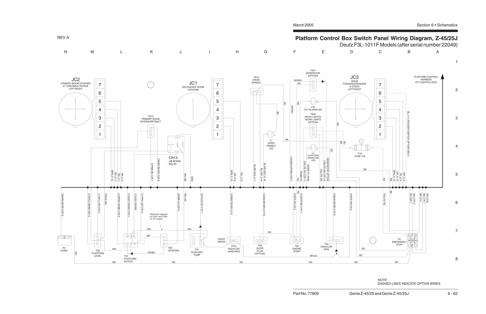
Platform Control Box Switch Panel Wiring Diagram, Z-45/25JDeutz F3L-1011F Models (after serial number 22049)
1
2
3
4
5
6
7
8
N M L K J I H G F E D C B A
Part No. 77809 Genie Z-45/25 and Genie Z-45/25J 6 - 62
March 2005 Section 6 • Schematics
REV A
P2EMERGENCY
STOPTS4HIGH/LOW
RPM
TS2ENGINESTART
TS15DRIVE
ENABLE
L1DRIVE
ENABLELED
DRIVESPEED
TS14HIGH/LOW(2WD/4WD)
TS13PRIMARY BOOM
EXTEND/RETRACT
TS8JIB BOOM
TS7PLATFORMROTATE
TS9PLATFORM
LEVEL
P3HORN TS1
AUXILIARYPUMP
C9
HR
NB
K/R
DC
3P
-9
RD
C1
4P
LU
OR
C4
P-2
C1
5P
LD
OR
/BK
C4
P-3
C1
8P
RR
GR
/BK
C4
P-6
C1
9JS
VG
R/W
HC
4P
-7
C1
7P
RL
GR
C4
P-5
C2
7A
UX
RD
C1
P-1
P2
5F
SR
DC
9-3
C3
3S
TR
BK
C1
P-7
BK
C9
P-1
WH
C7
P-2
RD
WH
GR/BK
RD
GR
RD
WH-24
RD RD RD
TS47GENERATOR
(OPTION)
C8
PB
RB
K/W
HC
3P
-8
BL
/RD
-DE
3J1
-16
C4
5G
EN
GR
/WH
C2
P-7
RD
BL
-DE
1J1
-6
GR/WH
RD
C7
PB
EB
KC
3P
-7
GR
/WH
RD
C2
9M
SR
D/W
HJ1
-8
TS6GLOWPLUG
(OPTION)
C3
4S
AB
K/W
HC
1P
-8
WHWH
White wire replacedby CR27 and CR30on CE models
GR
/BK
-44
C2
P-6
RD
NOTE:DASHED LINES INDICATE OPTION WIRES
C3
5H
SB
K/R
DC
1P
-9
2
1
NC
2
1
NC
BL
/BK
-DE
2J1
-7
4
2
1
3
5
6
7O
RJ1
-13
BR
NJ1
-14
WH
J1
-4
BL
J1
-5(R
OC
KE
RS
WIT
CH
OP
TIO
NO
NLY
)
OR
J1
-9
BR
NJ1
-10
YE
LJ1
-3
OR
J1
-11
BR
NJ1
-12
BK
J1
-2
RD
J1
-1
JC3DRIVE
FORWARD/REVERSE& STEER
LEFT/RIGHT
JC1SECONDARY BOOM
UP/DOWN
CR13JIB BOOMRELAY
WH
-JIB
C1
9JS
VG
R/W
H
P2
4F
SW
H
BR
N
WH
-JIB
P2
4F
SW
HC
9-2
RD
BK
BK
BK
BK
BK
BK
34 NO
PLATFORM CONTROLHARNESS
(TO CONTROL BOX)
BL
J1
-5
+
TS48DRIVE LIGHTS/WORK LIGHTS
(OPTION)
RD
RD
PD
LIT
ER
D
CW
LIT
ER
DC
2P
-11
CW
LIT
ER
DC
2P
-12
F18FUSE 10A
CD
LIT
EG
R
2
1
3
5
4
6
7
2
1
3
5
4
6
7JC2
PRIMARY BOOM UP/DOWN& TURNTABLE ROTATE
LEFT/RIGHT
GE
NE
RA
TO
RO
PT
ION
2
1
NC
BK
J3
-3
BK
C7
P-1
RD
LS
18
L48TILT ALARM LED
+
L4PLATFORMOVERLOAD
LED
+
GR
/BK
H1
(D3
9)
BK
RD
RD
RD
RD
RD
/BK
H1

Platform Control Box Switch Panel Wiring Diagram, Z-45/25JDeutz F3L-1011F Models (after serial number 22049)
March 2005 Section 6 • Schematics


Electrical Schematic, Z-45/25Perkins 104-22 Models (before serial number 22050)
1
2
3
4
5
6
7
8
A B C D E F G H I J K L M N
March 2005Section 6 • Schematics
6 - 63 Genie Z-45/25 and Genie Z-45/25J Part No. 77809
REV A
P2
3B
AT
WH
C2
3T
TS
RW
H
HO
RN
RE
LA
Y
LE
VE
LS
EN
SO
R
HO
RN
+
-
RD
P2
0B
AT
RD
TB20
C2
1IG
NW
H
C4
1R
PM
OR
/BK
CR5
C4
6H
RN
BK
/RD
RD
RD
CB215A
CB115A
TB41
C4
6H
RN
BK
/RD
TB23
KS1PLAT
GRD
P1
RD
P3HORN
TB22
P2
2B
AT
BK
BK-(FS)C9P-1 BKP2
GE
NE
RA
TO
RO
PT
ION
FL
AS
HIN
GB
EA
CO
NS
OP
TIO
N
HO
UR
ME
TE
R
PO
WE
RR
EL
AY
IGN
ITIO
N/S
TA
RT
RE
LA
Y
STA
RT
ER
MO
TO
R
AU
XIL
IAR
YP
UM
P
AU
XIL
IAR
YP
OW
ER
RE
LA
Y
TS2
GROUNDAUX. ON
KEY POWERBATTERY
TACHOMETER
IGN./FUEL ONENG. FAULT
KEY BYPASS
START INPUT
START RELAY
4
STARTERAUX
PUMP
PR1
RD
-27
-E.H
.
C2
8T
TA
RD
/BK
CR1
R3
3S
TR
BK
TB21
TB25
8765
109
CR2
TS51
C2
8T
TA
RD
/BK
TB27
RD
TS1RD
TS52
BK
1
2
TB33
3
C2
3A
LR
MR
D
IGNITION/START
MODULE
C2
1IG
NW
H
FB1
C3
3S
TR
BK
C4
5G
EN
GR
/WH
GE
NE
RA
TO
R
TS47
P24FS WH
C9P-3RD-(FS)
FS1
BR
N
TS54
TS4
BRN
RD
RD
P24FS WH
P26ESTP BK
OIL
TE
MP
ER
AT
UR
EL
ED
12 VDC
C9P-2
REGULATOR
IND.
ALTERNATOR
BAT.+
STA.
BAT.-
EXCT.
FU
EL
SO
LE
NO
ID
TB24
TB26
C2
6T
SR
WH
/RD
C2
5P
SR
WH
/BK
L43OIL
TEMP.
L42
PRESSOIL
SW2NC
SW3NO
OIL
PR
ES
SU
RE
SW
ITC
H
OIL
TE
MP
ER
AT
UR
ES
WIT
CH
OIL
PR
ES
SU
RE
LE
D
TB34
TS56
C3
4S
AB
K/W
H
TS6
PR3
CR4
HIG
HR
PM
SO
LE
NO
ID
HIG
HID
LE
RE
LA
Y
TIL
TA
LA
RM
P2
2B
AT
BK
WH-(FS)
H1
RD
WH
BR
NB
K
BK
C3
P-9
H2HM
+
_
C41RPM OR/BK
RD
P25FS RD
P26ESTP BK
C7
P-2
C1
P-2
C1
P-1
C2
7A
UX
RD
C7
P-1
C1
P-7
C1
P-8
C2
P-7
C1
P-9
C3
5H
SB
K/R
D
C4
1R
PM
OR
/BK
C28TTA RD/BKC28TTA RD/BK
C28TTA RD/BK
C41RPM OR/BKF
OO
TS
W.H
IGH
ENGINESPEED
HIG
HR
PM
LO
WR
PM
FU
NC
TIO
NE
NA
BL
E
C1
B-9
C5
-18
ON
ON
GL
OW
PL
UG
C1
B-8
ON
GL
OW
PL
UG
EN
GIN
ES
TA
RT
EN
GIN
ES
TA
RT
C5
-12
AU
XIL
IAR
YP
OW
ER
AU
XIL
IAR
YP
OW
ER
C1
B-7
C4
5G
EN
GR
/WH
C5
-22
C5
-14
C5
-16
C5
-11
C5
-12
C3
4S
AB
K/W
H
C5
-5
C21IGN WH
C2
1IG
N2
WH
C3
B-9
C5
-2
C5-3
C6
-27
C7
B-4
C5
-24
C5
-23
C2
B-7
B2
D1
M2M3
PR2
Q3
S8
U1
U32
C3
5H
SB
K/R
D
BK
/RD
C6
-34
C2
B-3
WO
RK
LIG
HT
DR
IVE
LIG
HT
LIG
HT
S
L30 L30
L29L29
FUSE 10A
C2
P-5
C2
B-5
C4
3D
LIT
EG
R
C2
P-11
C2
P-1
2C
2P
-10
C2
P-9
PBOX GND
RD
RD
CR23
DR
IVE
LIG
HT
OP
TIO
N
WO
RK
LIG
HT
SO
PT
ION
C6
-38
C6
-39
TS48
RD
RD
C7
B-1
FUSE 10A
BK/RD
P20BAT RD
A B
C
W
C3 3MF+
GL
OW
PL
UG
S

Electrical Schematic, Z-45/25Perkins 104-22 Models (before serial number 22050)
1
2
3
4
5
6
7
8
N M L K J I H G F E D C B A
Part No. 77809 Genie Z-45/25 and Genie Z-45/25J 6 - 64
March 2005 Section 6 • Schematics
REV A
P24FS WH
P26ESTP BK
C41RPM OR/BK
C28TTA RD/BK
BRN
RD
RD
RD
C1
B-1
0
TB1
C3
B-1
2
C3
B-1
0
C3
B-1
1
BK
-4
WH
-6TB8TB15TB17
BO
OM
RE
TR
AC
T
C6
TR
FW
H/R
D
PR
IMA
RY
BO
OM
DO
WN
PR
IMA
RY
BO
OM
UP
SE
CO
ND
AR
YB
OO
MF
LO
WC
ON
TR
OL
SE
CO
ND
AR
YB
OO
MD
OW
N
LS
4-S
EC
ON
DA
RY
BO
OM
UP
DR
IVE
LIM
ITS
WIT
CH
LS
1-P
RIM
AR
YB
OO
ME
XT
EN
DD
RIV
EL
IMIT
SW
ITC
H
LS
2-P
RIM
AR
YB
OO
MU
PD
RIV
EL
IMIT
SW
ITC
H
LS
3-D
RIV
EE
NA
BL
EL
IMIT
SW
ITC
H
PL
AT
FO
RM
LE
VE
LD
OW
N
DE
SC
EN
TA
LA
RM
OP
TIO
N
PL
AT
FO
RM
RO
TA
TE
RIG
HT
PL
AT
FO
RM
RO
TA
TE
RIG
HT
C7
PB
EB
K
C8
PB
RB
K/W
H
C1
5P
LD
OR
/BK
C1
4P
LU
OR
C1
7JU
GR
C1
8JD
GR
/BK
C5
-25
C2
2-1
C6
-19
H3
C2
2-2
PL
AT
FO
RM
LE
VE
LU
P
BO
OM
EX
TE
ND
C2
0-1
C2
0-2
C2
1-1
C2
3-1
C2
3-2
C2
1-2
C1
7-1
C1
6-1
C1
7-2
C1
6-2
C4
4D
AB
K
C6
-18
C6
-17
C6
-15
C6
-14
C6
-8
C6
-7
TB14
TB18 TB7
C1
PB
UR
D
C2
PB
DR
D/B
K
C3
PB
FR
D/W
H
C1
0S
BU
BL
C11
SB
DB
L/B
K
C1
0-1
WH
-6
C1
2S
BF
BL
/WH
SE
CO
ND
AR
YB
OO
MU
P
C11
-3 C6
-20
BK
-5
RD
C3
0-1C
6-1
3 C3
0-2
C1
9-2
C1
9-1
PR
IMA
RY
BO
OM
FL
OW
CO
NT
RO
L
C1
8-2
C1
8-1
C1
2-1
C2
9-1
C1
3-1
C2
9-2
C1
3-2
C1
2-2
Y22
TB10
C6
-10
BK C1
0-2
BK
-7
C1
0-4
WH
-5
14
13
LS3
BK
-6
C6
-12
C6
-11
WH
-4
LS4
22
21
C11
-2
WH
-7
TB12
C6
-16
TB11
C6
-3
C6
-1
C6
-2
TB3
TB2
TB6
DR
IVE
ED
CR
EV
ER
SE
DR
IVE
ED
CF
OR
WA
RD
BR
AK
ER
EL
EA
SE
VA
LV
E
TR
AV
EL
AL
AR
MO
PT
ION
TU
RN
TA
BL
ER
OTA
TE
LE
FT
TU
RN
TA
BL
ER
OTA
TE
RIG
HT
TU
RN
TA
BL
ER
OTA
TE
FL
OW
CO
NT
RO
L
C3
1R
EV
WH
/BK
C3
0F
WD
WH
C2
9M
SR
D/W
H
C3
2B
RK
WH
/RD
C3
2TA
WH
/RD
C3
7S
TC
BL
/BK
C3
6S
TC
CB
L
C4
TR
LW
H
C5
TR
RW
H/B
K
C2
8-1
C2
8-2
MO
TO
RS
TR
OK
E
ST
EE
RL
EF
T
ST
EE
RR
IGH
T
C1
4-1
C3
1-1
C1
5-1
C1
4-2
C3
1-2
C1
5-2
C2
5-1
C2
4-1
C2
5-2
C2
4-2
BR
N
BR
N
GR
OU
ND
RD
C2
6-1
C2
6-2
BK
H4 BK
RD
U4
C6
-5
C6
-4
C6
-6
C6
-37
C6
-36
C6
-29
TB5
TB4
C6
-32
C5
-20
C6
-33
C5
-21
TB32
PRIMARY BOOM UP/DOWN &TURNTABLE ROTATE
P2
4F
SW
H
CR27
P2
4F
SW
H
P2
6E
ST
PB
K
C1
5P
LD
OR
/BK
RE
TR
AC
T
EX
TE
ND
PR
IMA
RY
BO
OM
DO
WN
DO
WN
UP
UP
PL
AT
FO
RM
LE
VE
L
PL
AT
FO
RM
LE
VE
L
C4
B-6
C4
B-5
C4
B-2
C4
B-3
C3
B-8
TS59
C1
4P
LU
OR
C8
PB
RB
K/W
H
C4
P-2
C4
P-3
TS63
RE
TR
AC
T
EX
TE
ND
PR
IMA
RY
BO
OM
C4
P-6
C4
P-5
C3
P-8
TS9 TS13
C11
-1
C6
-40
C11
-4
DO
WN
UP
SE
CO
ND
AR
YB
OO
M
LS121
C1
0-3
C3
B-7
22
OR BK
-6
C4
B-4
C2
B-2
C7
PB
EB
K
C2
2L
SR
D
BK
C1
6P
DR
EO
R/R
D
TS60 C1
2S
BF
BL
/WH
C11
SB
DB
L/B
K
C3
B-3
C3
B-2
C3
B-1
C3
PB
FR
D/W
H
C1
0S
BU
BL
C2
PB
DR
D/B
K
C1
PB
UR
D
TS61
C2
P-2
C40LSS OR
C3
P-7
C4
P-4
U13 JOYSTICK CONTROL CARDCELIFT/DRIVEOPTION
4
NC
23 4
3
J3
1B
RN
13
12
14
C3
P-1
2
C3
P-1
0
C3
P-11
C3
P-2
C3
P-3
C3
P-1
3
10 9
J1
8 7
BR
N
OR
YE
L
11 2
12
J2
6
1
J1
RD
OR
BR
N
BK
1
P26ESTP BK
SECONDARY BOOMUP/DOWN
OU
T
PW
R
GN
D
42 3 5 6 7
JC1
GN
D21
YO
UT
PW
R
XO
UT
43 65
JC2
RIG
HT
LE
FT
DR
IVE
EN
AB
LE
CD
E1
BL
DR
IVE
MO
DE
CD
E3
BL
/RD
CD
E2
BL
/BK
C3
7S
TC
BL
/BK
C2
9M
SR
D/W
H
C3
B-4
C3
B-6
C3
B-5
C1
B-1
1
C1
B-3
C6
TR
FW
H/R
D
C4
TR
LW
H
C5
TR
RW
H/B
K
TS62 C3
6S
TC
CB
L
C3
1R
EV
WH
/BK
C3
2B
RK
WH
/RD
C1
B-6
C1
B-5
C1
B-4
C7
B-3
C3
0F
WD
WH
BA
TG
ND
20
17
11
18
10
R4
C3
P-6
C3
P-4
C3
P-5
C1
P-1
0
C1
P-11
C1
P-3
9
45
13
14
J1
6
WH
BR
N
OR
BL
BL
16
15
19
C4
1R
PM
OR
/BK
C1
P-6
C1
P-5
C2
P-3
C1
P-4
C7
P-3
8
167
J1
15
5
7
DRIVE & STEERING
YO
UT
PW
R
GN
D
31 2 54
RK
OU
T6 7
JC3
P24FS WH
P26ESTP BK
TS14
LS2
22
21
TS57
RIG
HT
RIG
HT
PL
AT
FO
RM
RO
TA
TE
PL
AT
FO
RM
RO
TA
TE
LE
FT
LE
FT
TS7
L1
TS15
C28TTA RD/BK
DO
WN
UP
PR
IMA
RY
BO
OM
LE
FT
RIG
HT
TU
RN
TA
BL
ER
OTA
TE
10
CR30NO
STEERROCKERSWITCHOPTION
WH
C1
7P
RL
GR
C1
8P
RR
GR
/BK

Electrical Schematic, Z-45/25Perkins 104-22 Models (before serial number 22050)
March 2005 Section 6 • Schematics


Electrical Schematic, Z-45/25Perkins 104-22 Models (after serial number 22049)
1
2
3
4
5
6
7
8
A B C D E F G H I J K L M N
March 2005Section 6 • Schematics
6 - 65 Genie Z-45/25 and Genie Z-45/25J Part No. 77809
REV A
C1
33
PL
AC
23
TT
SR
WH
HO
RN
RE
LA
Y
LE
VE
LS
EN
SO
R
HO
RN
+
-
RD
P2
0B
AT
RD
TB20
C2
1IG
NW
H
C4
1R
PM
OR
/BK
CR5NO
C4
6H
RN
BK
/RD
CB115A
RD
RD
CB215A
TB41
C4
6H
RN
BK
/RD
TB23
KS1
PLAT
GRD
P1
RD
P3
HORN
TB134
P2
2B
AT
BK
BK-(FS)C9P-1 BKP2
GE
NE
RA
TO
RO
PT
ION
FL
AS
HIN
GB
EA
CO
NS
OP
TIO
N
HO
UR
ME
TE
R
PO
WE
RR
EL
AY
IGN
ITIO
N/S
TA
RT
RE
LA
Y
STA
RT
ER
MO
TO
R
AU
XIL
IAR
YP
UM
P
AU
XIL
IAR
YP
OW
ER
RE
LA
Y
TS2
GROUNDAUX. ON
KEY PWR.BATTERY
TACHOMETER
IGN./FUEL ONENG. FAULT
KEY BYPASS
START INPUT
START RELAY
4
STARTERAUX
PUMP
PR1
C2
7A
UX
RD
PR1NO
C2
8T
TA
RD
/BK
CR1
NO
CR1
R3
3S
TR
BK
TB21
TB25
NO
CR2
8765
109
CR2
TS51
C2
8T
TA
RD
/BK
TB27
RD
TS1RD
TS52
BK
1
2
TB33
3
C2
1IG
NW
H
FB1
C3
3S
TR
BK
C4
5G
EN
GR
/WH
TS47
P24FS WH
C9P-3RD-(FS)
FS1
BR
N
TS54
TS4
BRN
RD
BK
P24FS WH
P26ESTP BK
CO
OL
AN
TT
EM
PE
RA
TU
RE
LE
D
C9P-2
REGULATOR
IND.
ALTERNATOR
BAT.+
STA.
BAT.-
EXCT.
FU
EL
SO
LE
NO
ID
TB24
TB26
C2
6T
SR
WH
/RD
C2
5P
SR
WH
/BK
L42OILPRES.
L43WATERTEMP.
SW2NC
SW3NO
OIL
PR
ES
SU
RE
SW
ITC
H
OIL
TE
MP
ER
AT
UR
ES
WIT
CH
OIL
PR
ES
SU
RE
LE
D
TB34
TS56
C3
4S
AB
K/W
H
TS6
PR3
CR4NO CR4
PR3NO
HIG
HR
PM
SO
LE
NO
ID
HIG
HID
LE
RE
LA
Y
TIL
TA
LA
RM
P2
2B
AT
BK
GL
OW
PL
UG
S
WH-(FS)
H1
RD
WH
BR
NB
K
BK
C3
P-9
H2HM
+
_
C41RPM OR/BK
RD
P25FS RD
P26ESTP BK
C4
P-1
C1
P-2
C1
P-1
C2
7A
UX
RD
C7
P-1
C1
P-7
C1
P-8
C2
P-7
GE
NE
RA
TO
R
C1
P-9
C3
5H
SB
K/R
D
C4
1R
PM
OR
/BK
C28TTA RD/BKC28TTA RD/BK
C28TTA RD/BK
C41RPM OR/BK
ENGINESPEED
HIG
HR
PM
LO
WR
PM
FU
NC
TIO
NE
NA
BL
E
C1
B-9
C5
-18
ON
GL
OW
PL
UG
C1
B-8
ON
GL
OW
PL
UG
EN
GIN
ES
TA
RT
EN
GIN
ES
TA
RT
C5
-12
AU
XIL
IAR
YP
UM
P
C1
B-7
C4
5G
EN
GR
/WH
C5
-22
C5
-14
C5
-16
C5
-11
C6
-9
C3
4S
AB
K/W
H
C5
-5
C21IGN WH
C2
1IG
N2
WH
C3
B-9
C5
-2
C5-3
C7
B-4
C5
-24
C2
B-7
B112V DC
D1
C3 3MF+
M2
M3
PR2PR2NO
Q3
S8
U1IGNITION/
STARTMODULE
U32
C3
5H
SB
K/R
D
BK
/RD
C6
-34
C2
B-3
WO
RK
LIG
HT
DR
IVE
LIG
HT
LIG
HT
S
L30 L30
L29L29
FUSE 10A (ONLY FOR WORKLIGHTS)
C2
P-5
C2
B-5
C4
3D
LIT
EG
R
C2
P-11
C2
P-1
2C
2P
-10
C2
P-9
PBOX GND
RD
RD
CR23NO
CR23
DR
IVE
LIG
HT
OP
TIO
N
WO
RK
LIG
HT
SO
PT
ION
C6
-38
C6
-39
TS48
RD
RD
C7
B-1
C1B & C1P = GRAYC2B & C2P = BLACKC3B & C3P = GREENC4B & C4P = BROWN
FUSE10A
BK/RD
P20BAT RD
A B
C
FO
OT
SW
ITC
HH
IGH
ON
SU
PR
ES
SIO
ND
IOD
E
C32
4
6
12 8
7
5
AU
XIL
AR
YP
UM
PC
1B
-1
L48
D3
D4
C7
P-2
P2
3B
AT
WH
C7
B-2
D2
D40
1 3
C1
P-1
2
C2
P-5
C1
32
PL
IB
L/W
H
C1
34
PW
RB
L/R
DC
2B
-5
C1
B-1
2
TB22
C4
B-1
C1
B-2
C23 ALARM RD
NOTE:
1. All switches and contacts are shown with the boomin the stowed position and the keyswitch off.
4
5 Add D40 only if unit has L4 and L48.
CE and Platform Overload Option
ANSI/CSA (Domestic machine) add L48.6
6
5

Electrical Schematic, Z-45/25Perkins 104-22 Models (after serial number 22049)
1
2
3
4
5
6
7
8
N M L K J I H G F E D C B A
Part No. 77809 Genie Z-45/25 and Genie Z-45/25J 6 - 66
March 2005 Section 6 • Schematics
REV A
TS7
TS57
WH
C1
7P
RL
GR
C1
8P
RR
GR
/BK
LE
FT
RIG
HT
PL
AT
RO
TA
TE
RIG
HT
PL
AT
FO
RM
RO
TA
TE
LE
FT
P26ESTP BK
C41RPM OR/BK
C28TTA RD/BK
BRN
RD
RD
BK
P24FS WH
WH
-4
BO
OM
RE
TR
AC
T
CR33
PL
AT
FO
RM
RO
TA
TE
RIG
HT
AN
DJIB
BO
OM
DO
WN
PL
AT
FO
RM
RO
TA
TE
LE
FT
AN
DJIB
BO
OM
UP
C6
-19
DE
SC
EN
TA
LA
RM
OP
TIO
N
H3
C2
2-2
C5
-25
C2
3-2
PL
AT
FO
RM
LE
VE
LD
OW
N
PL
AT
FO
RM
LE
VE
LU
P
BO
OM
EX
TE
ND
C2
1-2
C2
0-2
C1
6-2
C1
7-2
C4
4D
AB
K
C1
8JD
GR
/BK
C2
2-1
C2
3-1
C1
7JU
GR
C6
-18
C6
-17
C1
5P
LD
OR
/BK
C1
4P
LU
OR
C2
1-1
C2
0-1
C8
PB
RB
K/W
H
C1
6-1
C1
7-1
C7
PB
EB
K
C6
-15
C6
-14
C6
-8
C6
-7
C6
-20
BK
-5
C6
-13
LS
4-S
EC
ON
DA
RY
BO
OM
UP
DR
IVE
LIM
ITS
WIT
CH
LS
1-P
RIM
AR
YB
OO
ME
XT
EN
DD
RIV
EL
IMIT
SW
ITC
H
LS
2-P
RIM
AR
YB
OO
MU
PD
RIV
EL
IMIT
SW
ITC
H
LS
3-D
RIV
EE
NA
BL
EL
IMIT
SW
ITC
H
SE
CO
ND
AR
YB
OO
MU
P
SE
CO
ND
AR
YB
OO
MS
EL
EC
TR
EL
AY
SE
CO
ND
AR
YB
OO
MD
OW
N
C1
8-2
C1
9-2
PR
IMA
RY
BO
OM
UP
PR
IMA
RY
BO
OM
SE
LE
CT
RE
LA
Y
PR
IMA
RY
BO
OM
DO
WN
TU
RN
TA
BL
ER
OTA
TE
SE
LE
CT
RE
LA
Y
TU
RN
TA
BL
ER
OTA
TE
RIG
HT
TU
RN
TA
BL
ER
OTA
TE
LE
FT
C1
3-2
C1
4-2
C1
2-2
C1
5-2
BK LS3
C6
-10
C6
-11
C1
0-1
WH
-6RD
C11
-3B
K-7
C1
0-2
14
C11
SB
DB
L/B
K
C1
0S
BU
BL
C1
8-1
C1
9-1
LS2
22
21
C1
0-4
WH
-5
BK
-6
13
2
8587a 87
8630
CR37
C4
TR
LW
H
C5
TR
RW
H/B
K
C2
PB
DR
D/B
K
C1
3-1
C1
4-1
C1
2-1
C1
5-1
C1
PB
UR
D
8587a 87
8630
C6
-2
C6
-5
C6
-4
C6
-1
CR32
8587a 87
8630
BR
AK
ER
EL
EA
SE
VA
LV
E
TR
AV
EL
AL
AR
MO
PT
ION
MO
TO
RS
TR
OK
E
ST
EE
RL
EF
T
ST
EE
RR
IGH
T
C2
4-2
C2
5-2
C2
8-2
C2
6-2
DR
IVE
ED
CR
EV
ER
SE
DR
IVE
ED
CF
OR
WA
RD
GR
OU
ND
BR
N
BR
N
BK
RD
C3
7S
TC
BL
/BK
C3
6S
TC
CB
L
C2
4-1
C2
5-1
C2
9M
SR
D/W
H
C3
2B
RK
WH
/RD
C3
2TA
WH
/RD
C2
8-1
C2
6-1 H4
C6
-37
C6
-36
C6
-29
C6
-32
C6
-33
C3
1R
EV
WH
/BK
C3
0F
WD
WH
RD
BK
U4
C5
-20
C5
-21
TB5
C5
TR
RW
H/B
K
RE
TR
AC
T
EX
TE
ND
BO
OM
J3 J1 J1
C1
5P
LD
OR
/BK
RE
TR
AC
T
EX
TE
ND
BO
OM
DO
WN
DO
WN
UP
UP
PL
AT
FR
OM
LE
VE
L
PL
AT
FR
OM
LE
VE
L
C1
4P
LU
OR
C8
PB
RB
K/W
H
C7
PB
EB
K
C2
2L
SB
K
TB18
TB17
C4
B-5
TB14
C4
B-6
TB15
C4
B-2
C4
B-3
TB7
TB8
C3
B-8
C3
B-7
C4
P-5
C4
P-2
C4
P-3
TS59 TS63
C4
P-6
C3
P-8
C3
P-7
DO
WN
UP
BO
OM
SE
CO
ND
AR
Y
C1
6P
DR
EO
R/R
D
C1
2S
BF
BL
/WH
C11
SB
DB
L/B
K
DO
WN
UP
PR
IMA
RY
BO
OM
C3
PB
FR
D/W
H
C1
0S
BU
BL
C2
PB
DR
D/B
K
C1
PB
UR
D
LE
FT
RIG
HT
TU
RN
TA
BL
ER
OTA
TE
LS1
C1
0-3
WH
-6
21
WH
-7
22
LS4
C11
-2
C6
-16
22BK
-4
C4
B-4
TB10
TB12
TB11
C3
B-1
0
C3
B-1
1
C11
-4
21
OR BK
-6
C6
-40
C11
-1
TB3
C3
B-1
2
C3
B-3
C3
B-2
C3
B-1
TB2
TB6
TB1
C3
B-5
14
BK
C2
B-2
C40LSS OR
TS60
U13 JOYSTICK CONTROL CARD
C2
P-2
C4
P-4
CELIFT/DRIVEOPTION
4 3
C3
P-1
0
C3
P-1
1
12
13
TS61 TS62
20
R4
J2
C3
P-1
2
C3
P-2
C3
P-3
C3
P-1
8 7 6
C3
P-5
10
TS9 TS13
6
P2
4F
SW
H
P2
6E
ST
PB
K
CR30NO
3 4
CR27NC
P2
4F
SW
H BR
N
BR
N
OR
YE
L
12
10 9 3
1 2 3 4 5
PW
R
GN
D
OU
T
JC1
SECONDARY BOOMUP/DOWN
P26ESTP BK
BR
N1
2
7 21
GN
D
RD
OR
BK
211 1
543 6 7
PW
R
XO
UT
YO
UT
PRIMARY BOOM UP/DOWNAND TURNTABLE ROTATE
JC2
J1
C4
1R
PM
OR
/BK
J1C
37
ST
CB
L/B
K
C2
9M
SR
D/W
H
C6
TR
FW
H/R
D
C3
6S
TC
CB
L
C3
1R
EV
WH
/BK
C3
2B
RK
WH
/RD
C3
0F
WD
WH
BA
TG
ND
C3
B-6
C1
B-1
0
C1
B-1
1
TB32
C1
B-3
C1
B-6
C1
B-5
C1
B-4
C7
B-3
C3
P-6
C1
P-1
0
C1
P-1
1
18
119 17
C1
P-3
C1
P-6
20
19
C1
P-5
C2
P-3
C1
P-4
C7
P-3
15
16 5
C28TTA RD/BK
RIG
HT
LE
FT
DR
IVE
EN
AB
LE
RK
OU
T
L1
7
WHB
RN
OR
BL
BL
14 5
13 4
GN
D21 3 4 5 6
PW
R
YO
UT
DR
IVE
MO
DE
CD
E3
BL
/RD
CD
E2
BL
/BK
6 7
3
16 8
CD
E1
BL
P24FS WH
P26ESTP BK
DRIVE & STEERING
JC3TS15
15
TS14
3
NOTES:1. ALL LIMIT SWITCHES SHOWNWITH BOOM IN STOWED POSITIONEXCEPT AS NOTED.
SWITCH SHOWN WITH BOOMROTATED PAST EITHER NON-STEERWHEEL.
ROCKER STEER OPTION ONLY.
2
C1B & C1P - GRAYC2B & C2P - BLACKC3B & C3P - GREENC4B & C4P - BROWN

Electrical Schematic, Z-45/25Perkins 104-22 Models (after serial number 22049)
March 2005 Section 6 • Schematics

Ground Control Box Terminal Strip Wiring Diagram, Z-45/25Perkins 104-22 Models (before serial number 22050)
March 2005Section 6 • Schematics
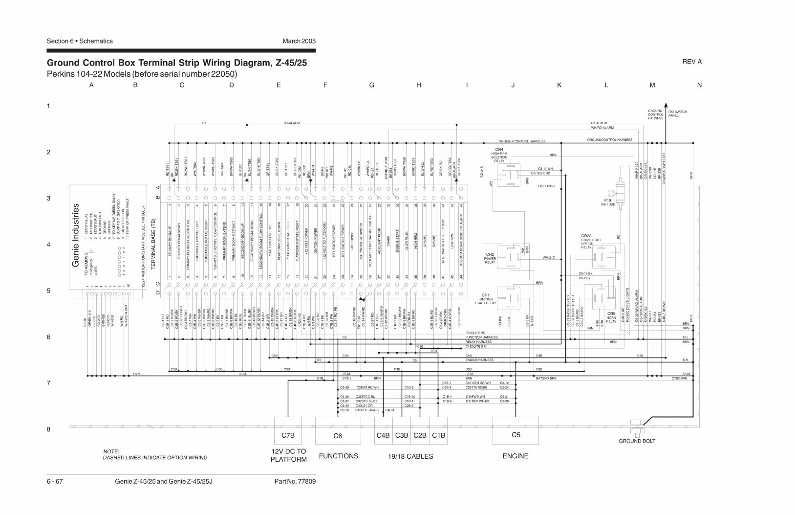
Ground Control Box Terminal Strip Wiring Diagram, Z-45/25Perkins 104-22 Models (before serial number 22050)
1
2
3
4
5
6
7
8
A B C D E F G H I J K L M N
March 2005Section 6 • Schematics
6 - 67 Genie Z-45/25 and Genie Z-45/25J Part No. 77809
REV A
DC
PR
IMA
RY
BO
OM
UP
1 2 3 4 5 6 7 8 10
PR
IMA
RY
BO
OM
DO
WN
PR
IMA
RY
BO
OM
FL
OW
CO
NT
RO
L
TU
RN
TA
BL
ER
OTA
TE
LE
FT
TU
RN
TA
BL
ER
OTA
TE
RIG
HT
TU
RN
TA
BL
ER
OTA
TE
FL
OW
CO
NT
RO
L
PR
IMA
RY
BO
OM
EX
TE
ND
PR
IMA
RY
BO
OM
RE
TR
AC
T
SE
CO
ND
AR
YB
OO
MU
P
+1
2V
OLT
PO
WE
R
PL
AT
FO
RM
RO
TA
TE
RIG
HT
PL
AT
FO
RM
RO
TA
TE
LE
FT
PL
AT
FO
RM
LE
VE
LD
OW
N
PL
AT
FO
RM
LE
VE
LU
P
SE
CO
ND
AR
YB
OO
MF
LO
WC
ON
TR
OL
SE
CO
ND
AR
YB
OO
MD
OW
N
2011
15
17
18
14
12
AU
XIL
IAR
YP
UM
P
CO
OL
AN
TT
EM
PE
RA
TU
RE
SW
ITC
H
KE
YS
WIT
CH
PO
WE
R
IGN
ITIO
NP
OW
ER
21
25
27
26
23
24
HIG
HR
PM
EN
GIN
ES
TA
RT
BR
AK
E
39
35
38
33
34
32
LO
WR
PM
ALT
ER
NA
TO
RP
UL
SE
PIC
KU
P4
1
44
42
BA
C6
-1R
D
C3
B-1
RD
C6
-2R
D/B
K
C3
B-2
RD
/BK
C3
B-3
RD
/WH
C6
-4W
H
C3
B-4
WH
C6
-5W
H/B
K
C3
B-5
WH
/BK
C6
-6W
H/R
D
C6
-7B
K
C3
B-7
BK
C6
-8B
K/W
H
C3
B-8
BK
/WH
C6
-10
BL
C3
B-1
0B
L
C6
-11
BL
/BK
C3
B-1
1B
L/B
K
C6
-12
BL
/WH
C3
B-1
2B
L/W
H
C6
-14
OR
C6
-15
OR
/BK
C6
-17
GR
C4
B-5
GR
C6
-18
GR
/BK
C4
B-6
GR
/BK
C1
B-1
RD
C7
B-4
RD
C5
-3W
H
C7
B-1
BK
C7
B-2
WH
C1
B-6
WH
/RD
C6
-32
WH
/RD
C1
B-7
BK
C5
-22
BK
/WH
C2
B-3
OR
/BK
C5
-2O
R/B
K
C2
B-6
GR
/BK
RD
-TS
61
RD
/BK
-TS
61
WH
-TS
62
WH
/BK
-TS
62
BK
-TS
63
BK
/WH
-TS
63
BL
-TS
60
BL
/BK
-TS
60
BL
/WH
-TS
60
OR
-TS
59
OR
/BK
-TS
59
GR
-TS
57
GR
/BK
-TS
57
RD
-CB
1
BK
/RD
-TS
54
RD
/WH
-TS
61
WH
/RD
-TS
62
C3
B-6
WH
/RD
C1B
C4B
C5
BATGND BRN
ENGINE HARNESS
FUNCTION HARNESS
WH
-23
B
RD
-27
B
GROUND CONTROL HARNESS
(TO SWITCHPANEL)
E.H.
F.H.
OR
/BK
-IS
2
TE
RM
INA
LB
AS
E(T
B)
1 2 3 4 5 6 7 8 10
11
15
17
18
14
12
20
24
26
27
25
23
21
38
39
34
35
32
33
44
42
41
GROUNDCONTROL HARNESS
GROUNDCONTROLHARNESS
1 2 3 4 5 6 7 8 9 10
1 2 3 4 5 6 7 8 9 10
STA
RT
RE
LA
Y
TA
CH
OM
ET
ER
STA
RT
INP
UT
AU
XP
WR
UN
IT
GR
OU
ND
BA
TT
ER
Y
TO
KE
YS
W(D
IES
EL
ON
LY
)
JU
MP
TO
7(G
AS
ON
LY
)
IGN
OR
FU
EL
ON
TE
MP
OR
PR
ES
SF
AU
LT
13
47
10
92
12
/24
Vo
ltIG
NIT
ON
/STA
RT
MO
DU
LE
P/N
56
05
7
Ge
nie
Ind
ustr
ies
TO
RE
MO
VE
:
Pu
sh
ge
ntly
an
dlif
t
(SP
AR
E)
BK
-R1
OR
/BK
-41
A
BK
-33
B
RD
-27
B
BR
N-I
S5
WH
-R2
RD
-CR
1
C6
-3R
D/W
H
C4
B-2
OR
C4
B-3
OR
/BK
C6
-27
RD
WH
-IS
7
WH
-KS
RD
-TS
51
BK
-33
TS
52
BK
/RD
-R4
OR
/BK
-41
A
WH
-IS
7
RD
-IS
4
OR
/BK
-IS
2
BK
-IS
1
WH
-IS
9
C5
-5B
K
C7B3 BRN
I.S.M. I.S.M. I.S.M. I.S.M.
C6
C4B
C5
C7B
WH
/RD
-AL
AR
M
BK-ALARMBK-ALARMBK
C6
-33
WH
/RD
-AL
AR
M
C5
-19
BK
-AL
AR
M
WH
/RD
-32
A
BK
-AL
AR
M
C6
-34
RD
FB
BK
BK
WH/RD-ALARM
JIB
BO
OM
DO
WN
DE
SC
EN
TA
LA
RM
BR
NB
RN
GROUND BOLT
NOTE:DASHED LINES INDICATE OPTION WIRING
RD
-IS
6
RD
-IS
4
FUNCTIONS ENGINE19/18 CABLES
C5C6 C2B C1BC3BC4B
12V DC TOPLATFORM
C7B
CB
1P
OW
ER
WH
/RD
-L3
-C3BC3B C3B C3B C3B
C2B
C2
B-1
BL
/RD
(SP
AR
E)
BL
/RD
-TS
53
BL
/WH
-L2
-
OIL
PR
ES
SU
RE
SW
ITC
H
CR5HORNRELAY
BR
N
WH-21C
RD
-24
B
C6-13 BK
C6
-9B
K/R
D
BRN
BRNBRN
BR
N
BRN
C3
B-9
BK
/RD
C3B
+1
2V
OLT
TO
PL
AT
FO
RM
22
22
C5
-23
WH
BK-22B
C7B-3
CR4
SOLENOIDRELAY
HIGH RPM
C5-18 BK/RD
BR
N
WH
BR
N
WH
CR1
START RELAYIGNITION
CR2
RELAYPOWER
BK/RD-35C
C16DRE OR/RDC6-16 C4B-4
C1
9JS
VG
R/W
HT
S5
7C
4B
-7G
R/W
H
C43DLITE GR
C4B C4BC4B
C36STCC BLC6-36 C1B-10
C37STC BL/BKC6-37 C1B-11
C30FWD WHC1B-4 C5-21
C31REV WH/BKC1B-5 C5-20
C28TTA RD/BK C5-24C1B-2C29MS RD/WHC6-29 C1B-3
C40LS1 ORC6-40 C2B-2G
LO
WP
LU
GC
1B
-8B
K/W
H
WH
-25
D&
26
D
C1
B-9
BK
/RD
C6
-20
RD
BR
N
BK
/WH
-TS
56
WH
/BK
-L2
-
C5-11 WH
BK
-R5
OR
/RD
-TS
54
OR
/RD
-CR
3
BRN
CR23DRIVE LIGHTOPTIONRELAY
C6
-38
R4
3D
LIT
E1
RD
C6
-39
R4
3D
LIT
E2
RD
BRN
BR
NR
D
P20DLITE RD
C2
B-5
GR
WH
-IS
10
C2
B-4
OR
/RD
BRN
BRN
F1910A FUSE
C5
-14
WH
/RD
C45 GEN GR/WH C5-12C2B-7
RD
-R2
RD
-CB
1
RD
-CB
2C
R2
3R
D
RD
-20
CD
RIV
EL
IGH
TS
WH
-HM
WH
-R2
KE
YS
WIT
CH
PO
WE
R2
32
3
C5
-16
WH
/RD
GR
/BK
-TS
58
BK
-AL
AR
M
RELAY HARNESS
I.S.M.
BRN
WH
-23
B
BK
-33
BB
K-I
S3
BK
-IS
3
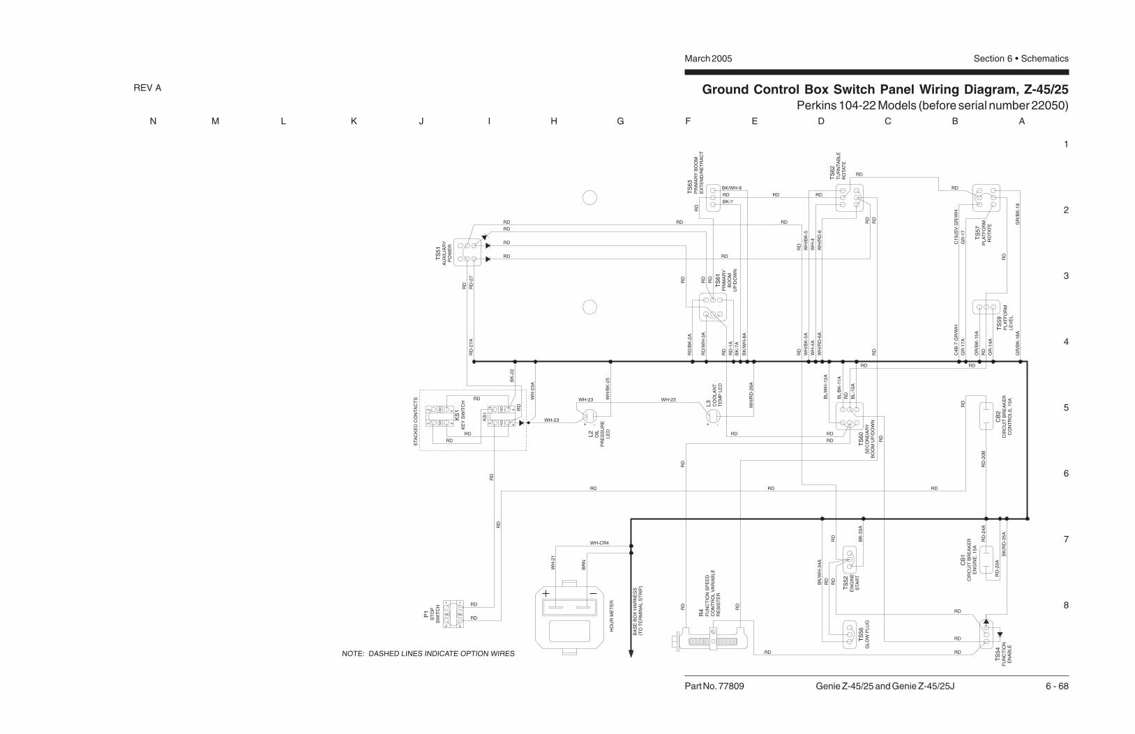
Ground Control Box Switch Panel Wiring Diagram, Z-45/25Perkins 104-22 Models (before serial number 22050)
1
2
3
4
5
6
7
8
N M L K J I H G F E D C B A
Part No. 77809 Genie Z-45/25 and Genie Z-45/25J 6 - 68
March 2005 Section 6 • Schematics
REV A
HO
UR
ME
TE
R
KS
1K
EY
SW
ITC
H
BA
SE
BO
XH
AR
NE
SS
(TO
TE
RM
INA
LS
TR
IP)
BK
/RD
-35
A
RD
-20
B
RD
RD
RD
RD
-20
A
BK
-33
A
RD
RD
RD
RD
RD
RD
RDRD
RDRDRD
RD
RDRD
WH
-21
BR
N
RD
RD
GR
/BK
-18
GR
/BK
-18
A
RD
GR
-17
GR
-17
A
C1
9JS
VG
R/W
HC
4B
-7G
R/W
H
OR
-14
A
RD
OR
/BK
-15
A
RDRD
BL
/WH
-12
A
BL
/BK
-11
A
RD
BL
-10
A
RD
RD
RD
RD
RD
RDRD
WH
/RD
-6
WH
-4
WH
/BK
-5
WH
/RD
-6A
WH
-4A
WH
/BK
-5A
RD
RD
RDRD RD
RDRD RD
RD
RD
RD
BK
/WH
-8A
BK
-7A
RD
-1A
RD
RD
/WH
-3A
RD
/BK
-2A
RD
BK/WH-8
BK-7
RD
RD
WH-23
WH
-23
A
RD
BK
-22
RD
RD
-27
RD
-27
A
RD
RD
RD
KS
1
TS
59
PL
AT
FO
RM
LE
VE
L
TS
57
PL
AT
FO
RM
RO
TA
TE
CB
2B
RE
AK
ER
CO
NT
RO
LS
,1
5A
CIR
CU
IT
CB
1B
RE
AK
ER
EN
GIN
E,1
5A
CIR
CU
IT
TS
54
FU
NC
TIO
NE
NA
BL
E
TS
52
EN
GIN
ES
TA
RT
TS
60
SE
CO
ND
AR
YB
OO
MU
P/D
OW
N
TS
62
TU
RN
TA
BL
ER
OTA
TE
TS
63
PR
IMA
RY
BO
OM
EX
TE
ND
/RE
TR
AC
T
TS
61
PR
IMA
RY
BO
OM
UP
/DO
WN
R4
CO
NT
RO
LV
AR
IAB
LE
RE
SIS
TE
R
FU
NC
TIO
NS
PE
ED
TS
51
AU
XIL
IAR
YP
OW
ER
P1
ST
OP
SW
ITC
H
STA
CK
ED
CO
NTA
CT
S
L2
OIL
PR
ES
SU
RE
LE
D
BK
/WH
-34
A
RD
RD
RD
NOTE: DASHED LINES INDICATE OPTION WIRES
TS
56
GL
OW
PL
UG
3 4NO
3 4NO
3
4NO
3 4NO
1
2
NC
1
2
NC
-+
WH-23WH-23
WH
/RD
-26
A
WH
/BK
-25
L3
CO
OL
AN
TT
EM
PL
ED
RD
-24
A
-+
WH-CR4

Ground Control Box Switch Panel Wiring Diagram, Z-45/25Perkins 104-22 Models (before serial number 22050)
March 2005 Section 6 • Schematics
Ground Control Box Terminal Strip Wiring Diagram, Z-45/25Perkins 104-22 Models (after serial number 22049)
March 2005Section 6 • Schematics
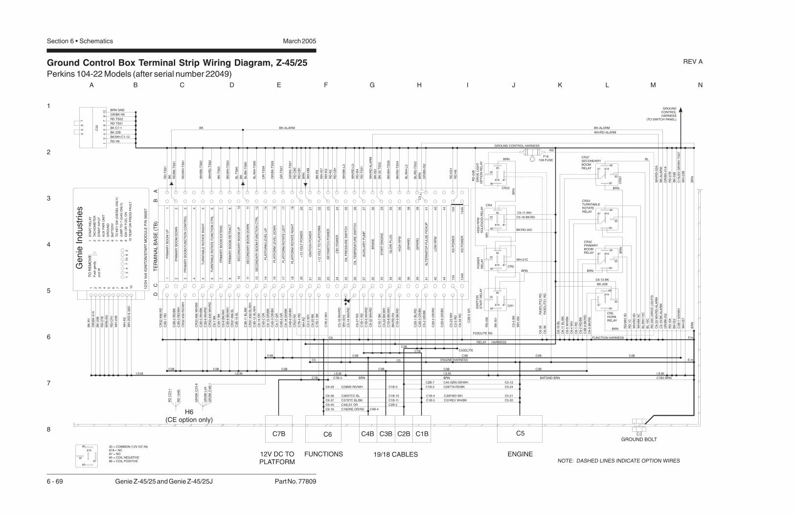
Ground Control Box Terminal Strip Wiring Diagram, Z-45/25Perkins 104-22 Models (after serial number 22049)
1
2
3
4
5
6
7
8
A B C D E F G H I J K L M N
March 2005Section 6 • Schematics
6 - 69 Genie Z-45/25 and Genie Z-45/25J Part No. 77809
REV A
DC
PR
IMA
RY
BO
OM
UP
1 2 3 4 5 6 7 8 10
PR
IMA
RY
BO
OM
DO
WN
PR
IMA
RY
BO
OM
FU
NC
TIO
NC
ON
TR
OL
TU
RN
TA
BL
ER
OTA
TE
RIG
HT
TU
RN
TA
BL
ER
OTA
TE
FU
NC
TIO
NC
TR
L
PR
IMA
RY
BO
OM
EX
TE
ND
PR
IMA
RY
BO
OM
RE
TR
AC
T
SE
CO
ND
AR
YB
OO
MU
P
+1
2V
OLT
PO
WE
R
PL
AT
FO
RM
RO
TA
TE
RIG
HT
PL
AT
FO
RM
RO
TA
TE
LE
FT
PL
AT
FO
RM
LE
VE
LD
OW
N
PL
AT
FO
RM
LE
VE
LU
P
SE
CO
ND
AR
YB
OO
MF
UN
CT
ION
CT
RL
SE
CO
ND
AR
YB
OO
MD
OW
N
2011
15
17
18
14
12
AU
XIL
IAR
YP
UM
P
OIL
PR
ES
SU
RE
SW
ITC
H
KE
YS
WIT
CH
PO
WE
R
IGN
ITIO
NP
OW
ER
21
25
27
26
23
24
HIG
HR
PM
STA
RT
EN
GIN
E
BR
AK
E
39
35
38
33
34
32
LO
WR
PM
ALT
ER
NA
TO
RP
UL
SE
PIC
KU
P4
1
44
42
BA
CR
32
#8
6R
D
C3
B-1
RD
C3
B-2
RD
/BK
C3
B-3
RD
/WH
CR
33
#8
6W
H/B
K
C3
B-5
WH
/BK
C3
B-6
WH
/RD
C6
-7B
K
C3
B-7
BK
C6
-8B
K/W
H
C3
B-8
BK
/WH
CR
37
#8
6B
L
C3
B-1
0B
L
C3
B-1
1B
L/B
K
CR
37
#3
0B
L/W
H
C3
B-1
2B
L/W
H
C6
-14
OR
C6
-15
OR
/BK
C6
-17
GR
C4
B-5
GR
C6
-18
GR
/BK
C4
B-6
GR
/BK
C1
B-1
RD
C7
B-4
RD
C5
-3W
H
C7
B-1
BK
C7
B-2
WH
C1
B-6
WH
/RD
C6
-32
WH
/RD
C1
B-7
BK
C2
B-3
OR
/BK
C5
-2O
R/B
K
C2
B-6
GR
/BK
RD
-TS
61
RD
/BK
-TS
61
WH
/BK
-TS
62
BK
-TS
63
BK
/WH
-TS
63
BL
-TS
60
BL
/BK
-TS
60
BL
/WH
-TS
60
OR
-TS
59
OR
/BK
-TS
59
GR
-TS
57
GR
/BK
-TS
57
RD
-CB
1
BK
/RD
-TS
54
RD
/WH
-TS
61
WH
/RD
-TS
62
CR
33
#3
0W
H/R
D
C1B
C4B
C5
BATGND BRN
ENGINE HARNESS
FUNCTION HARNESS
RD
-27
B
GROUND CONTROL HARNESS
E.H.
F.H.
OR
/BK
-IS
2
TE
RM
INA
LB
AS
E(T
B)
1 2 3 4 5 6 7 8 10
11
15
17
18
14
12
20
24
26
27
25
23
21
38
39
34
35
32
33
44
42
41
GROUNDCONTROLHARNESS
(TO SWITCH PANEL)
1 2 3 4 5 6 7 8 9 10
1 2 3 4 5 6 7 8 9 10
STA
RT
RE
LA
Y
TA
CH
OM
ET
ER
STA
RT
INP
UT
AU
XP
WR
UN
IT
GR
OU
ND
BA
TT
ER
Y
TO
KE
YS
W(D
IES
EL
ON
LY
)
JU
MP
TO
7(G
AS
ON
LY
)
IGN
OR
FU
EL
ON
TE
MP
OR
PR
ES
SF
AU
LT
13
47
10
92
12
/24
Vo
ltIG
NIT
ON
/STA
RT
MO
DU
LE
P/N
56
05
7
Ge
nie
Ind
ustr
ies
TO
RE
MO
VE
:
Pu
sh
ge
ntly
an
dlif
t
BK
-R1
OR
/BK
-41
A
BK
-33
B
RD
-27
B
BR
N-I
S5
WH
-23
B
WH
-R2
RD
-CR
1
CR
32
#3
0R
D/W
H
C4
B-2
OR
C4
B-3
OR
/BK
C6
-27
RD
WH
-KS
RD
-TS
51
BK
-33
TS
52
OR
/BK
-41
A
RD
-IS
4
OR
/BK
-IS
2
BK
-IS
1
WH
-IS
9
C5
-5B
K
C7B3 BRN
I.S.M. I.S.M. I.S.M. I.S.M.
C6
C4B
C5
C7B
WH
/RD
-AL
AR
M
BK-ALARMBK-ALARMBK
C6
-33
WH
/RD
-AL
AR
M
C5
-19
BK
-AL
AR
M
WH
/RD
-32
A
BK
-AL
AR
M
BK
BK
WH/RD-ALARM
BR
NB
RN
GROUND BOLT
NOTE: DASHED LINES INDICATE OPTION WIRES
RD
-IS
6
RD
-IS
4
FUNCTIONS ENGINE19/18 CABLES
C5C6 C2B C1BC3BC4B
12V DC TOPLATFORM
C7B
CB
1P
OW
ER
OIL
TE
MP
ER
AT
UR
ES
WIT
CH
WH
/RD
-L3
-
C3BC3B C3B C3B C3B
C2B
C2
B-1
BL
/RD
(SP
AR
E)
(SP
AR
E)
BL
/RD
-TS
53
BL
/WH
-L2
-
BK
/RD
-R4
CR2
CR1B
RN
WH-21C
RD
-24
B
BRN
C3B
+1
2V
OLT
TO
PL
AT
FO
RM
22
22
C7B-3
HIG
HR
PM
SO
LE
NO
IDR
EL
AY
C5-18 BK/RD
WH
IGN
ITIO
NS
TA
RT
RE
LA
YP
OW
ER
RE
LA
Y
BK/RD-35C
C16DRE OR/RDC6-16 C4B-4
C1
9JS
VG
R/W
HT
S5
7C
4B
-7G
R/W
H
C43DLITE
C4B C4BC4B
C36STCC BLC6-36 C1B-10
C37STC BL/BKC6-37 C1B-11
C30FWD WHC1B-4 C5-21
C31REV WH/BKC1B-5 C5-20
C28TTA RD/BK C5-24C1B-2C29MS RD/WHC6-29 C1B-3
C40LS1 ORC6-40 C2B-2
GL
OW
PL
UG
C5
-22
BK
/WH
C1
B-8
BK
/WH
WH
-25
D&
26
D
C1
B-9
BK
/RD
C6
-20
BK
BK
/WH
-TS
56
WH
/BK
-L2
-
C5-11 WH
BK
-R5
CR4
BRN
R4
3D
LIT
E1
RD
R4
3D
LIT
E2
RD
P20DLITE RD
C2
B-5
GR
WH
-IS
10
C2
B-4
OR
/RD
C5
-14
WH
/RD
C45 GEN GR/WH C5-12C2B-7
RD
-R2
RD
-CB
1
RD
-CB
2C
R2
3R
D
RD
-20
CD
RIV
EL
IGH
TS
WH
-HM
WH
-R2
WH
-IS
7
C5
-16
WH
/RD
RELAY HARNESS
I.S.M.
BRN
WH
-23
BW
H-I
S7
BK
-33
BB
K-I
S3
BK
-IS
3
CR23
F1910A FUSE
C6-13 BK
BK-22B
RD
DR
IVE
LIG
HT
OP
TIO
NR
EL
AY
CR
37
BRN
BRN
BR
N
RD
/WH
3D
RD
1C
C6
-2R
D/B
K
C6
-1R
D
30
85
87
86
87A
30 = COMMON (12V DC IN)87A = NC87 = NO85 = COIL NEGATIVE86 = COIL POSITIVE
C6
-5W
H/B
K
C6
-10
BL
C6
-4W
H
C6
-11
BL
/BK
WH
/RD
6D
WH
/BK
5C
BL
/WH
12
C
BL
10
C
30
30
30
30
30
30
85
85
85
85
85
85
87
8787
87
87
87
86
86
86
86
86
86
87A
87A
87A
87A
87A
87A
30
85
87
86
87A
30
85
87
86
87A
BLBRN
BR
N
13
4K
SP
OW
ER
13
4A
KS
PO
WE
R
RD
KS
1C
5-2
3W
H
C2
-5R
D
C6
-34
RD
BRN GND
GR/BK H6
RD TS52
RD TS51
BK C7-1
BK 22B
BK/WH C1-12
RD H6
C3
2
13
44
55
66
77
81
2
RD
H6
RD
C2
3-1
RD
13
4B
GR
/BK
C2
3-8
GR
/BK
L4
5
GR
/BK
C4
B-1
BRN
C6
-38
C6
-39
CR5HORNRELAY
C3
B-9
BK
/RD
13
4A
13
4
CR32
RELAY
PRIMARYBOOM
CR33
RELAY
TURNTABLEROTATE
CR37SECONDARY
RELAYBOOM
C6
-9B
K/R
D
BR
NC
3
+
H6(CE option only)

Ground Control Box Switch Panel Wiring Diagram, Z-45/25Perkins 104-22 Models (after serial number 22049)
1
2
3
4
5
6
7
8
N M L K J I H G F E D C B A
Part No. 77809 Genie Z-45/25 and Genie Z-45/25J 6 - 70
March 2005 Section 6 • Schematics
REV A
P1 RED EMERGENCY STOP BUTTON
KS1 KEY SWITCH
TS51 AUXILIARY POWER TOGGLE SWITCH
TS52 ENGINE START TOGGLE SWITCH
TS54 FUNCTION ENABLE TOGGLE SWITCH
TS56 GLOW PLUG TOGGLE SWITCH
TS57 PLATFORM ROTATE TOGGLE SWITCH
TS59 PLATFORM LEVEL TOGGLE SWITCH
TS63 PRIMARY BOOM EXTEND/RETRACT TOGGLE SWITCH
TS61 PRIMARY BOOM UP/DOWN TOGGLE SWITCH
TS62 TURNTABLE ROTATE TOGGLE SWITCH
LABEL DESCRIPTION
TS60 SECONDARY BOOM UP/DOWN TOGGLE SWITCH
CB1 CIRCUIT BREAKER, ENGINE, 15A
CB2 CIRCUIT BREAKER, CONTROLS, 15A
HM HOUR METER
R4 SPEED LIMITING VARIABLE RESISTOR 20 OHMS
L42 OIL PRESSURE LED
CR1 IGNITION / START RELAY
CR2 IG ITION POWER RELAYN
CR4 HIGH IDLE RELAY
CR5 HORN RELAY
L43 COOLANT TEMPERATURE LED
HIGH IDLE RELAY
L45 PLATFORM OVERLOAD
HO
UR
ME
TE
R
BA
SE
BO
XH
AR
NE
SS
(TO
TE
RM
INA
LS
TR
IP)
BK
/RD
-35
A
RD
-20
B
RD
RD
C2
3-7
RD
RD
-20
A
BK
-33
A
RD
RD
RD
RD
RD
RD
RD
RD
RD
RD
RD
RDRD
RDRDRD
RDRDRD
RD
RDRD
RDRD
BRN
WH
-21
BR
N
RD
RD
RD
RD
GR
/BK
-18
GR
/BK
-18
A
RD
RD
GR
GR
-17
GR
-17
A
C1
9JS
VG
R/W
HC
4B
-7G
R/W
H
OR
-14
A
RD
OR
/BK
-15
A
RDRD
BL
/WH
-12
A
BL
/BK
-11
A
RD
BL
-10
A
RD
RDRD
RD
RDRDRDRDRD
WH
/RD
-6
WH
-4
WH
/BK
-5
WH
/RD
-6A
WH
-4A
WH
/BK
-5A
RDRD
RDRD
RD
RDRD RD
RD
RD
RD
RD
BK
/WH
-8A
BK
-7A
RD
-1A
RD
RD
/WH
-3A
RD
/BK
-2A
RD
BK/WH-8
BK-7
RD
RD
WH-23WH-23
WH
/RD
-26
A
WH
/BK
-25
WH-23
RD
13
4A
RD
-27
RD
-27
A
WH
TS
59
PL
AT
FO
RM
LE
VE
L
TS
57
PL
AT
FO
RM
RO
TA
TE
CB
2C
IRC
UIT
BR
EA
KE
RC
ON
TR
OL
S1
5A
CB
1C
IRC
UIT
BR
EA
KE
RE
NG
INE
15
A
TS
54
FU
NC
TIO
NE
NA
BL
E
TS
52
STA
RT
EN
GIN
E
TS
60
SE
CO
ND
AR
YB
OO
MU
P/D
OW
N
TS
62
TU
RN
TA
BL
ER
OTA
TE
TS
63
PR
IMA
RY
BO
OM
EX
TE
ND
/R
ET
RA
CT
TS
61
PR
IMA
RY
BO
OM
UP
/DO
WN
L4
3C
OO
LA
NT
TE
MP
LE
DR
4F
UN
CT
ION
SP
EE
DC
ON
TR
OL
VA
RIA
BL
ER
ES
IST
ER
TS
51
AU
XIL
IAR
YP
OW
ER
P1
EM
ER
GE
NC
YS
TO
PS
WIT
CH
L4
2O
ILP
RE
SS
UR
EL
ED
RD
RD
RD
RD
1
2
NC
1
2
NC
-+
RD
-24
A
TS
56
GL
OW
PL
UG
-+
BK
/WH
-34
A
RD
WH-CR4
BK-22A
WH
-23
A
GR
/BK
H6
RD
C2
3-6
RD
L4
5P
LA
TF
OR
MO
VE
RL
OA
DL
ED
(CE
ON
LY
)
-+
KS
1

Ground Control Box Switch Panel Wiring Diagram, Z-45/25Perkins 104-22 Models (after serial number 22049)
March 2005 Section 6 • Schematics

Platform Control Box Wiring Diagram, Z-45/25Perkins 104-22 Models (before serial number 22050)
March 2005 Section 6 • Schematics

Platform Control Box Wiring Diagram, Z-45/25Perkins 104-22 Models (before serial number 22050)
1
2
3
4
5
6
7
8
A B C D E F G H I J K L M N
March 2005Section 6 • Schematics
6 - 71 Genie Z-45/25 and Genie Z-45/25J Part No. 77809
REV A
RE
D/B
LK
-28
RE
D-T
ILT
RE
D-T
ILT
BR
NB
RN
C3P
F.S.
C7P
C3P
C7PBATGRN C7P-3
C1P
PLATFORM CONTROL HARNESS(TO SWITCH PANEL)
H1TILT
ALARM12V DC BATTERY
C1
P(G
Y)
19/18 CONTROL CABLE
C7P C9
FOOT SWITCH
JIB OPT.
9
1
J1
JC
3-3
OR
DR
EA
BL
/WH
JC
3-2
BR
N
DR
EB
BL
/BK
C1
3L
ED
BL
/RD
C2
9M
SR
D/W
H
JC
2-5
BK
JC
1-5
YE
L
JC
2-3
OR
JC
3-4
BL
*
JC
2-2
BR
N
JC
3-5
WH
JC
1-3
OR
JC
2-4
RD
JC
1-2
BR
N
J2
1
11
1
P2
4F
SW
H
P2
4F
SW
H
P2
6E
ST
PB
K
J3
3
C2
P(B
K)
C3
P(G
R)
C4
P(B
R)
C28TTA RD/BK C1P-2
BR
N
C2
9M
SR
D/W
HC
1P
-3
C4
TR
LW
HC
3P
-4
C3
2B
RK
WH
/RD
C1
P-6
C5
TR
RW
H/B
KC
3P
-5
C3
6S
TC
CB
KC
1P
-10
C3
PB
FR
D/W
HC
3P
-3
C3
7S
TC
BL
/BK
C1
P-11
C2
PB
DR
D/B
KC
3P
-2
C3
1R
EV
WH
/BK
C1
P-5
C1
PB
UR
DC
3P
-1
C3
0F
WD
WH
C1
P-4
C4
1R
PM
OR
/BK
C2
P-3
C1
2S
BF
BL
/WH
C3
P-1
2
C4
0L
SS
OR
C2
P-2
C11
SB
DB
L/B
KC
3P
-11
C1
6D
RE
OR
/RD
C4
P-4
C1
0S
BU
BL
C3
P-1
0
C6
TR
FW
H/R
DC
3P
-6
C2
8T
TA
RD
/BK
C1
P-2
C2P
C2
7A
UX
RD
C1
P-1
C3
3S
TR
BK
C1
P-7
C3
5H
SB
K/R
DC
1P
-9
C3
4S
AB
K/W
HC
1P
-8
C4P
C4
5G
EN
GR
/WH
C2
P-7
P2
4F
SW
HC
9-2
P2
5F
SR
DC
9-3
P2
6B
AT
BK
C9
-1
C7
PB
EB
KC
3P
-7
C8
PB
RB
K/W
HC
3P
-8
C9
HR
NB
K/R
DC
3P
-9
C1
4P
LU
OR
C4
P-2
C1
5P
LD
OR
/BK
C4
P-3
P2
2B
AT
BK
C7
P-1
P2
3S
WB
AT
WH
C7
P-2
* NOTE:
WIRE CONNECTS TOJC3-6 FOR STEER ROCKERSWITCH OPTION.
U13ALC-500
CR30 CR27
P2
4F
SW
HC
9P
-2
C4
0L
SS
OR
C2
P-2
C3
2B
RK
WH
/RD
C1
P-6
WH/RD C1P-6
C3
2B
RK
WH
/RD
J2
-19
C4
0L
SS
OR
J2
-4
CE LIFT/DRIVE OPTION R2
4F
SW
HC
9P
-2
CW
LIT
ER
DC
2P
-11
CW
LIT
ER
DC
2P
-12
CD
LIT
EG
RC
2P
-5
WLITE BRN C2P-10
WLITE BRN C2P-9
BRN
BRNBRN
BR
N

Platform Control Box Switch Panel Wiring Diagram, Z-45/25Perkins 104-22 Models (before serial number 22050)
1
2
3
4
5
6
7
8
N M L K J I H G F E D C B A
Part No. 77809 Genie Z-45/25 and Genie Z-45/25J 6 - 72
March 2005 Section 6 • Schematics
REV A
P2EMERGENCY
STOP
TS4HIGH/LOW
RPMTS2
START
TS15DRIVE ENABLE
L1
TS14HIGH/LOW(2WD/4WD)
TS13PRIMARY BOOM
EXTEND/RETRACT
TS7PLATFORM
ROTATETS9
PLATFORMLEVEL
P3HORN
TS1AUXILIARY
POWER
C9
HR
NB
K/R
DC
3P
-9
C1
4P
LU
OR
C4
P-2
C1
5P
LD
OR
/BK
C4
P-3
C1
8P
RR
GR
/BK
C4
P-6
C1
9JS
VG
R/W
HC
4P
-7
C1
7P
RL
GR
C4
P-5
C2
7A
UX
RD
C1
P-1
P2
5F
SR
DC
9-3
C3
3S
TR
BK
C1
P-7
P2
3B
AT
WH
C7
P-2
P2
6B
AT
BK
C9
P-1
P2
6B
AT
BK
-LO
AD
P2
2B
AT
BK
C7
P-1
RD
RD
WH
RD
WH-24
RD RD
TS47GENERATOR
(OPTION)
C8
PB
RB
K/W
HC
3P
-8
BL
/RD
-DE
3J1
-16
C4
5G
EN
GR
/WH
C2
P-7
RD
BL
-DE
1J1
-6
GR/WH
RD
C7
PB
EB
KC
3P
-7
C2
9M
SR
D/W
HJ1
-8
C3
4S
AB
K/W
HC
1P
-8
TS6GLOW PLUG
WHWH
RD
NOTE: DASHED LINES INDICATE OPTION WIRES
RD
-TIL
T
C3
5H
SB
K/R
DC
1P
-9
12 NC
1
2
NC
BL
/BK
-DE
2J1
-7
4
2
1
3
5
6
7O
RJ1
-13
BR
NJ1
-14
WH
J1
-4
BL
J1
-5(R
OC
KE
RS
WIT
CH
OP
TIO
NO
NLY
)
OR
J1
-9
BR
NJ1
-10
YE
LJ1
-3
OR
J1
-11
BR
NJ1
-12
BK
J1
-2
RD
J1
-1
JC3DRIVE
FORWARD/REVERSE& STEER
LEFT/RIGHT
JC1SECONDARY BOOM
UP/DOWN
JC2PRIMARY BOOM UP/DOWN
& TURNTABLE ROTATELEFT/RIGHT
P2
4F
SW
HC
9-2
RD
BK
BK
BK
BK
BK
BK
34 NO
PLATFORMCONTROLHARNESS
(TO CONTROL BOX)
BL
J1
-5
+
TS48DRIVE LIGHTS/WORK LIGHTS
(OPTION)
RD
RD
PD
LIT
ER
D
CW
LIT
ER
DC
2P
-11
CW
LIT
ER
DC
2P
-12
F18
FUSE 10A
CD
LIT
EG
RC
2P
-5
2
1
3
5
4
6
7
2
1
3
5
4
6
7
GE
NE
RA
TO
RO
PT
ION
Platform Control Box Switch Panel Wiring Diagram, Z-45/25Perkins 104-22 Models (before serial number 22050)
March 2005 Section 6 • Schematics

Platform Control Box Wiring Diagram, Z-45/25Perkins 104-22 Models (after serial number 22049)
March 2005 Section 6 • Schematics

Platform Control Box Wiring Diagram, Z-45/25Perkins 104-22 Models (after serial number 22049)
1
2
3
4
5
6
7
8
A B C D E F G H I J K L M N
March 2005Section 6 • Schematics
6 - 73 Genie Z-45/25 and Genie Z-45/25J Part No. 77809
REV A
TILTALALRM
RE
D/B
LK
-28
RE
D-T
ILTR
ED
-TILT
C2
P-5
BR
NB
RN
C3P
F.S.
C7P
C3P
C7PBATGRN C7P-3
C1P
PLATFORM CONTROLHARNESS
(TO SWITCH PANEL)
H1
12V DC BATTERYSUPPLY
C1
P(G
Y)
19/18 CONTROL CABLE
C7P C9
FOOT SWITCH
JIBBOOM
OPTION
9
1
J1
JC
3-3
OR
DR
EA
BL
/WH
JC
3-2
BR
N
DR
EB
BL
/BK
C1
3L
ED
BL
/RD
C2
9M
SR
D/W
H
JC
2-5
BK
JC
1-5
YE
L
JC
2-3
OR
JC
3-4
BL
*
JC
2-2
BR
N
JC
3-5
WH
JC
1-3
OR
JC
2-4
RD
JC
1-2
BR
N
J2
1
11
1
P2
4F
SW
H
P24FS WH
P2
6E
ST
PB
K
J3
3
C2
P(B
K)
C3
P(G
R)
C4
P(B
R)
C28TTA RD/BK C1P-2
BR
N
C2
9M
SR
D/W
HC
1P
-3
C3
2B
RK
WH
/RD
C1
P-6
C5
TR
RW
H/B
KC
3P
-5
C3
6S
TC
CB
KC
1P
-10
C3
PB
FR
D/W
HC
3P
-3
C3
7S
TC
BL
/BK
C1
P-11
C2
PB
DR
D/B
KC
3P
-2
C3
1R
EV
WH
/BK
C1
P-5
C1
PB
UR
DC
3P
-1
C3
0F
WD
WH
C1
P-4
C4
1R
PM
OR
/BK
C2
P-3
C1
2S
BF
BL
/WH
C3
P-1
2
C4
0L
SS
OR
C2
P-2
C11
SB
DB
L/B
KC
3P
-11
C1
6D
RE
OR
/RD
C4
P-4
C1
0S
BU
BL
C3
P-1
0
C6
TR
FW
H/R
DC
3P
-6
C2
8T
TA
RD
/BK
H1
C2P
C2
7A
UX
RD
C1
P-1
C3
3S
TR
BK
C1
P-7
C3
5H
SB
K/R
DC
1P
-9
C3
4S
AB
K/W
HC
1P
-8
C4P
C4
5G
EN
GR
/WH
C2
P-7
P2
4F
SW
HC
9-2
P2
5F
SR
DC
9-3
P2
6B
AT
BK
C9
-1
C7
PB
EB
KC
3P
-7
C8
PB
RB
K/W
HC
3P
-8
C9
HR
NB
K/R
DC
3P
-9
C1
4P
LU
OR
C4
P-2
C1
5P
LD
OR
/BK
C4
P-3
P2
2B
AT
BK
C7
P-1
P2
3S
WB
AT
WH
C7
P-2
* NOTE: WIRE CONNECTS TO JC3-6 FOR STEER ROCKER SWITCH OPTION.
U13ALC-500
CW
LIT
ER
DC
2P
-11
CW
LIT
ER
DC
2P
-12
CD
LIT
EG
R
WLITE BRN C2P-10
WLITE BRN C2P-9
BR
N
Y
GR
/BK
-L4
GR
/BK
C4
P-1
H1
J3
J2
J1
U13
C1P - C4P
C7P
ALC-500 CONTROL BOARD
CONTROL BOARD POWER CONNECTOR
CONTROL BOARD OUTPUT CONNECTOR
CONTROL BOARD INPUT CONNECTOR
TILT ALARM
12V DC PLATFORM POWER CONNECTOR
48 PIN CONNECTOR BLOCK
DESCRIPTIONITEM
FOOT SWITCH CONNECTORC9
RD
-P2
RD
-H1
C1
33
PL
AG
R/B
KC
4P
-1
RE
DL
S1
8

Platform Control Box Switch Panel Wiring Diagram, Z-45/25Perkins 104-22 Models (after serial number 22049)
1
2
3
4
5
6
7
8
N M L K J I H G F E D C B A
Part No. 77809 Genie Z-45/25 and Genie Z-45/25J 6 - 74
March 2005 Section 6 • Schematics
REV A
P2EMERGENCY
STOPTS4HIGH/LOW
RPM
TS2ENGINESTART
TS15DRIVE
ENABLE
L1DRIVE
ENABLELED
DRIVESPEED
TS14HIGH/LOW(2WD/4WD)
TS13PRIMARY BOOM
EXTEND/RETRACT
TS7PLATFORMROTATE
TS9PLATFORM
LEVEL
P3HORN TS1
AUXILIARYPUMP
C9
HR
NB
K/R
DC
3P
-9
RD
C1
4P
LU
OR
C4
P-2
C1
5P
LD
OR
/BK
C4
P-3
C1
8P
RR
GR
/BK
C4
P-6
C1
9JS
VG
R/W
HC
4P
-7
C1
7P
RL
GR
C4
P-5
C2
7A
UX
RD
C1
P-1
P2
5F
SR
DC
9-3
C3
3S
TR
BK
C1
P-7
BK
C9
P-1
WH
C7
P-2
RD
WH
RD RD
WH-24
RD RD RD
TS47GENERATOR
(OPTION)
C8
PB
RB
K/W
HC
3P
-8
BL
/RD
-DE
3J1
-16
C4
5G
EN
GR
/WH
C2
P-7
RD
BL
-DE
1J1
-6
GR/WH
RD
C7
PB
EB
KC
3P
-7
GR
/WH
RD
C2
9M
SR
D/W
HJ1
-8
TS6GLOWPLUG
C3
4S
AB
K/W
HC
1P
-8
WHWH
RD
NOTE:DASHED LINES INDICATE OPTION WIRES
C3
5H
SB
K/R
DC
1P
-9
2
1
NC
2
1
NC
BL
/BK
-DE
2J1
-7
4
2
1
3
5
6
7O
RJ1
-13
BR
NJ1
-14
WH
J1
-4
BL
J1
-5(R
OC
KE
RS
WIT
CH
OP
TIO
NO
NLY
)
OR
J1
-9
BR
NJ1
-10
YE
LJ1
-3
OR
J1
-11
BR
NJ1
-12
BK
J1
-2
RD
J1
-1
JC3DRIVE
FORWARD/REVERSE& STEER
LEFT/RIGHT
JC1SECONDARY BOOM
UP/DOWN
P2
4F
SW
HC
9-2
RD
BK
BK
BK
BK
BK
BK
34 NO
PLATFORM CONTROLHARNESS
(TO CONTROL BOX)
BL
J1
-5
+
TS48DRIVE LIGHTS/WORK LIGHTS
(OPTION)
RD
RD
PD
LIT
ER
D
CW
LIT
ER
DC
2P
-11
CW
LIT
ER
DC
2P
-12
F18FUSE 10A
CD
LIT
EG
R
2
1
3
5
4
6
7
2
1
3
5
4
6
7JC2
PRIMARY BOOM UP/DOWN& TURNTABLE ROTATE
LEFT/RIGHT
GE
NE
RA
TO
RO
PT
ION
2
1
NC
BK
J3
-3
BK
C7
P-1
RD
LS
18
L48TILT ALARM LED
+
BK
RD
RD
RD
/BK
H1

Platform Control Box Switch Panel Wiring Diagram, Z-45/25Perkins 104-22 Models (after serial number 22049)
March 2005 Section 6 • Schematics


Electrical Schematic, Z-45/25JPerkins 104-22 Models (before serial number 22050)
1
2
3
4
5
6
7
8
A B C D E F G H I J K L M N
March 2005Section 6 • Schematics
6 - 75 Genie Z-45/25 and Genie Z-45/25J Part No. 77809
REV A
P2
3B
AT
WH
C2
3T
TS
RW
H
HO
RN
RE
LA
Y
LE
VE
LS
EN
SO
R
HO
RN
+
-
RD
P2
0B
AT
RD
TB20
C2
1IG
NW
H
C4
1R
PM
OR
/BK
CR5
C4
6H
RN
BK
/RD
RD
RD
CB215A
CB115A
TB41
C4
6H
RN
BK
/RD
TB23
KS1PLAT
GRD
P1
RD
P3HORN
TB22
P2
2B
AT
BK
BK-(FS)C9P-1 BKP2
GE
NE
RA
TO
RO
PT
ION
FL
AS
HIN
GB
EA
CO
NS
OP
TIO
N
HO
UR
ME
TE
R
PO
WE
RR
EL
AY
IGN
ITIO
N/S
TA
RT
RE
LA
Y
STA
RT
ER
MO
TO
R
AU
XIL
IAR
YP
UM
P
AU
XIL
IAR
YP
OW
ER
RE
LA
Y
TS2
GROUNDAUX. ON
KEY POWERBATTERY
TACHOMETER
IGN./FUEL ONENG. FAULT
KEY BYPASS
START INPUT
START RELAY
4
STARTERAUX
PUMP
PR1
RD
-27
-E.H
.
C2
8T
TA
RD
/BK
CR1
R3
3S
TR
BK
TB21
TB25
8765
109
CR2
TS51
C2
8T
TA
RD
/BK
TB27
RD
TS1RD
TS52
BK
1
2
TB33
3
C2
3A
LR
MR
D
IGNITION/START
MODULE
C2
1IG
NW
H
FB1
C3
3S
TR
BK
C4
5G
EN
GR
/WH
GE
NE
RA
TO
R
TS47
P24FS WH
C9P-3RD-(FS)
FS1
BR
N
TS54
TS4
BRN
RD
RD
P24FS WH
P26ESTP BK
OIL
TE
MP
ER
AT
UR
EL
ED
12 VDC
C9P-2
REGULATOR
IND.
ALTERNATOR
BAT.+
STA.
BAT.-
EXCT.
FU
EL
SO
LE
NO
ID
TB24
TB26
C2
6T
SR
WH
/RD
C2
5P
SR
WH
/BK
L43OIL
TEMP.
L42
PRESSOIL
SW2NC
SW3NO
OIL
PR
ES
SU
RE
SW
ITC
H
OIL
TE
MP
ER
AT
UR
ES
WIT
CH
OIL
PR
ES
SU
RE
LE
D
TB34
TS56
C3
4S
AB
K/W
H
TS6
PR3
CR4
HIG
HR
PM
SO
LE
NO
ID
HIG
HID
LE
RE
LA
Y
TIL
TA
LA
RM
P2
2B
AT
BK
WH-(FS)
H1
RD
WH
BR
NB
K
BK
C3
P-9
H2HM
+
_
C41RPM OR/BK
RD
P25FS RD
P26ESTP BK
C7
P-2
C1
P-2
C1
P-1
C2
7A
UX
RD
C7
P-1
C1
P-7
C1
P-8
C2
P-7
C1
P-9
C3
5H
SB
K/R
D
C4
1R
PM
OR
/BK
C28TTA RD/BKC28TTA RD/BK
C28TTA RD/BK
C41RPM OR/BKF
OO
TS
W.
HIG
H
ENGINESPEED
HIG
HR
PM
LO
WR
PM
FU
NC
TIO
NE
NA
BL
E
C1
B-9
C5
-18
ON
ON
GL
OW
PL
UG
C1
B-8
ON
GL
OW
PL
UG
EN
GIN
ES
TA
RT
EN
GIN
ES
TA
RT
C5
-12
AU
XIL
IAR
YP
OW
ER
AU
XIL
IAR
YP
OW
ER
C1
B-7
C4
5G
EN
GR
/WH
C5
-22
C5
-14
C5
-16
C5
-11
C5
-12
C3
4S
AB
K/W
H
C5
-5
C21IGN WH
C2
1IG
N2
WH
C3
B-9
C5
-2
C5-3
C6
-27
C7
B-4
C5
-24
C5
-23
C2
B-7
B2
D1
M2M3
PR2
Q3
S8
U1
U32
C3
5H
SB
K/R
D
BK
/RD
C6
-34
C2
B-3
WO
RK
LIG
HT
DR
IVE
LIG
HT
LIG
HT
S
L30 L30
L29L29
FUSE 10A
C2
P-5
C2
B-5
C4
3D
LIT
EG
R
C2
P-11
C2
P-1
2C
2P
-10
C2
P-9
PBOX GND
RD
RD
CR23
DR
IVE
LIG
HT
OP
TIO
N
WO
RK
LIG
HT
SO
PT
ION
C6
-38
C6
-39
TS48
RD
RD
C7
B-1
FUSE 10A
BK/RD
P20BAT RD
A B
C
W
C3 3MF+
GL
OW
PL
UG
S

Electrical Schematic, Z-45/25JPerkins 104-22 Models (before serial number 22050)
1
2
3
4
5
6
7
8
N M L K J I H G F E D C B A
Part No. 77809 Genie Z-45/25 and Genie Z-45/25J 6 - 76
March 2005 Section 6 • Schematics
REV A
P24FS WH
P26ESTP BK
C41RPM OR/BK
C28TTA RD/BK
BRN
RD
RD
RDC
1B
-10
TB1
C3
B-1
2
C3
B-1
0
C3
B-1
1
BK
-4
WH
-6TB8TB15TB17
BO
OM
RE
TR
AC
T
C6
TR
FW
H/R
D
PR
IMA
RY
BO
OM
DO
WN
PR
IMA
RY
BO
OM
UP
SE
CO
ND
AR
YB
OO
MF
LO
WC
ON
TR
OL
SE
CO
ND
AR
YB
OO
MD
OW
N
LS
4-S
EC
ON
DA
RY
BO
OM
UP
DR
IVE
LIM
ITS
WIT
CH
LS
1-P
RIM
AR
YB
OO
ME
XT
EN
DD
RIV
EL
IMIT
SW
ITC
H
LS
2-P
RIM
AR
YB
OO
MU
PD
RIV
EL
IMIT
SW
ITC
H
LS
3-D
RIV
EE
NA
BL
EL
IMIT
SW
ITC
H
PL
AT
FO
RM
LE
VE
LD
OW
N
DE
SC
EN
TA
LA
RM
OP
TIO
N
JIB
BO
OM
DO
WN
/P
LA
TF
OR
MR
OTA
TE
RIG
HT
JIB
BO
OM
UP
/P
LA
TF
OR
MR
OTA
TE
RIG
HT
C7
PB
EB
K
C8
PB
RB
K/W
H
C1
5P
LD
OR
/BK
C1
4P
LU
OR
C1
7JU
GR
C1
8JD
GR
/BK
C5
-25
C2
2-1
C6
-19
H3
C2
2-2
PL
AT
FO
RM
LE
VE
LU
P
BO
OM
EX
TE
ND
C2
0-1
C2
0-2
C2
1-1
C2
3-1
C2
3-2
C2
1-2
C1
7-1
C1
6-1
C1
7-2
C1
6-2
C4
4D
AB
K
C6
-18
C6
-17
C6
-15
C6
-14
C6
-8
C6
-7
TB14
TB18 TB7
C1
PB
UR
D
C2
PB
DR
D/B
K
C3
PB
FR
D/W
H
C1
0S
BU
BL
C11
SB
DB
L/B
K
C1
0-1
WH
-6
C1
2S
BF
BL
/WH
SE
CO
ND
AR
YB
OO
MU
P
C11
-3 C6
-20
BK
-5
RD
C3
0-1C
6-1
3 C3
0-2
C1
9-2
C1
9-1
PR
IMA
RY
BO
OM
FL
OW
CO
NT
RO
L
C1
8-2
C1
8-1
C1
2-1
C2
9-1
C1
3-1
C2
9-2
C1
3-2
C1
2-2
Y22
TB10
C6
-10
BK C1
0-2
BK
-7
C1
0-4
WH
-5
14
13
LS3
BK
-6
C6
-12
C6
-11
WH
-4
LS4
22
21
C11
-2
WH
-7
TB12
C6
-16
TB11
C6
-3
C6
-1
C6
-2
TB3
TB2
TB6
DR
IVE
ED
CR
EV
ER
SE
DR
IVE
ED
CF
OR
WA
RD
BR
AK
ER
EL
EA
SE
VA
LV
E
TR
AV
EL
AL
AR
MO
PT
ION
TU
RN
TA
BL
ER
OTA
TE
LE
FT
TU
RN
TA
BL
ER
OTA
TE
RIG
HT
TU
RN
TA
BL
ER
OTA
TE
FL
OW
CO
NT
RO
L
C3
1R
EV
WH
/BK
C3
0F
WD
WH
C2
9M
SR
D/W
H
C3
2B
RK
WH
/RD
C3
2TA
WH
/RD
C3
7S
TC
BL
/BK
C3
6S
TC
CB
L
C4
TR
LW
H
C5
TR
RW
H/B
K
C2
8-1
C2
8-2
MO
TO
RS
TR
OK
E
ST
EE
RL
EF
T
ST
EE
RR
IGH
T
C1
4-1
C3
1-1
C1
5-1
C1
4-2
C3
1-2
C1
5-2
C2
5-1
C2
4-1
C2
5-2
C2
4-2
BR
N
BR
N
GR
OU
ND
RD
C2
6-1
C2
6-2
BK
H4 BK
RD
U4
C6
-5
C6
-4
C6
-6
C6
-37
C6
-36
C6
-29
TB5
TB4
C6
-32
C5
-20
C6
-33
C5
-21
TB32
PRIMARY BOOM UP/DOWN &TURNTABLE ROTATE
P2
4F
SW
H
CR27
P2
4F
SW
H
P2
6E
ST
PB
K
C1
5P
LD
OR
/BK
RE
TR
AC
T
EX
TE
ND
BO
OM
DO
WN
DO
WN
UP
UP
PL
AT
FO
RM
LE
VE
L
PL
AT
FO
RM
LE
VE
L
C4
B-6
C4
B-5
C4
B-2
C4
B-3
C3
B-8
TS59
C1
4P
LU
OR
C8
PB
RB
K/W
H
C4
P-2
C4
P-3
TS63
RE
TR
AC
T
EX
TE
ND
BO
OMC
4P
-6
C4
P-5
C3
P-8
TS9 TS13
C11
-1
C6
-40
C11
-4
DO
WN
UP
BO
OM
SE
CO
ND
AR
Y
LS121
C1
0-3
C3
B-7
22
OR BK
-6
C4
B-4
C2
B-2
C7
PB
EB
K
C2
2L
SR
D
BK
C1
6P
DR
EO
R/R
D
TS60 C1
2S
BF
BL
/WH
C11
SB
DB
L/B
K
C3
B-3
C3
B-2
C3
B-1
C3
PB
FR
D/W
H
C1
0S
BU
BL
C2
PB
DR
D/B
K
C1
PB
UR
D
TS61
C2
P-2
C40LSS OR
C3
P-7
C4
P-4
U13 JOYSTICK CONTROL CARDCELIFT/DRIVEOPTION
4
NC
23 4
3
J3
1B
RN
13
12
14
C3
P-1
2
C3
P-1
0
C3
P-11
C3
P-2
C3
P-3
C3
P-1
3
10 9
J1
8 7
BR
N
OR
YE
L
11 2
12
J2
6
1
J1
RD
OR
BR
N
BK
1
P26ESTP BK
SECONDARY BOOMUP/DOWN
OU
T
PW
R
GN
D
42 3 5 6 7
JC1
GN
D21
YO
UT
PW
R
XO
UT
43 65
JC2
RIG
HT
LE
FT
DR
IVE
EN
AB
LE
CD
E1
BL
DR
IVE
MO
DE
CD
E3
BL
/RD
CD
E2
BL
/BK
C3
7S
TC
BL
/BK
C2
9M
SR
D/W
H
C3
B-4
C3
B-6
C3
B-5
C1
B-1
1
C1
B-3
C6
TR
FW
H/R
D
C4
TR
LW
H
C5
TR
RW
H/B
KTS62 C
36
ST
CC
BL
C3
1R
EV
WH
/BK
C3
2B
RK
WH
/RD
C1
B-6
C1
B-5
C1
B-4
C7
B-3
C3
0F
WD
WH
BA
TG
ND
20
17
11
18
10
R4C
3P
-6
C3
P-4
C3
P-5
C1
P-1
0
C1
P-11
C1
P-3
9
45
13
14
J1
6
WH
BR
N
OR
BL
BL
16
15
19
C4
1R
PM
OR
/BK
C1
P-6
C1
P-5
C2
P-3
C1
P-4
C7
P-3
8
167
J1
15
5
7
DRIVE & STEERING
YO
UT
PW
R
GN
D
31 2 54
RK
OU
T6 7
JC3
P24FS WH
P26ESTP BK
TS14
LS2
22
21
JIB
VA
LV
ES
C1
8JD
GR
/BK
C1
7JU
GR
JD
AL
AR
MG
R/B
K
C1
9JS
VG
R/W
H
TS58
UP
DO
WN
JIB
BO
OM
RIG
HT
PL
AT
FO
RM
RO
TA
TE
LE
FT
C4
B-7
TS57
C2
B-6
TB44
C19JSV GR/WH
RIG
HT
PL
AT
FO
RM
RO
TA
TE
LE
FT
C4
P-7
JIB
VA
LV
ES
CR13TS7
UP
DO
WNJIB
BO
OM
C2
P-6
GR
/BK
-44
TS8
BRN
WH
NCCR13
L1
TS15
C28TTA RD/BK
DO
WN
UP
PR
IMA
RY
BO
OM
LE
FT
RIG
HT
TU
RN
TA
BL
ER
OTA
TE
10
CR30NO
STEERROCKERSWITCHOPTION
Electrical Schematic, Z-45/25JPerkins 104-22 Models (before serial number 22050)
March 2005 Section 6 • Schematics


Electrical Schematic, Z-45/25JPerkins 104-22 Models (after serial number 22049)
1
2
3
4
5
6
7
8
A B C D E F G H I J K L M N
March 2005Section 6 • Schematics
6 - 77 Genie Z-45/25 and Genie Z-45/25J Part No. 77809
REV A
C1
33
PL
AC
23
TT
SR
WH
HO
RN
RE
LA
Y
LE
VE
LS
EN
SO
R
HO
RN
+
-
RD
P2
0B
AT
RD
TB20
C2
1IG
NW
H
C4
1R
PM
OR
/BK
CR5NO
C4
6H
RN
BK
/RD
CB115A
RD
RD
CB215A
TB41
C4
6H
RN
BK
/RD
TB23
KS1
PLAT
GRD
P1
RD
P3
HORN
TB134
P2
2B
AT
BK
BK-(FS)C9P-1 BKP2
GE
NE
RA
TO
RO
PT
ION
FL
AS
HIN
GB
EA
CO
NS
OP
TIO
N
HO
UR
ME
TE
R
PO
WE
RR
EL
AY
IGN
ITIO
N/S
TA
RT
RE
LA
Y
STA
RT
ER
MO
TO
R
AU
XIL
IAR
YP
UM
P
AU
XIL
IAR
YP
OW
ER
RE
LA
Y
TS2
GROUNDAUX. ON
KEY PWR.BATTERY
TACHOMETER
IGN./FUEL ONENG. FAULT
KEY BYPASS
START INPUT
START RELAY
4
STARTERAUX
PUMP
PR1
C2
7A
UX
RD
PR1NO
C2
8T
TA
RD
/BK
CR1
NO
CR1
R3
3S
TR
BK
TB21
TB25
NO
CR2
8765
109
CR2
TS51
C2
8T
TA
RD
/BK
TB27
RD
TS1RD
TS52
BK
1
2
TB33
3
C2
1IG
NW
H
FB1
C3
3S
TR
BK
C4
5G
EN
GR
/WH
TS47
P24FS WH
C9P-3RD-(FS)
FS1
BR
N
TS54
TS4
BRN
RD
BK
P24FS WH
P26ESTP BK
CO
OL
AN
TT
EM
PE
RA
TU
RE
LE
D
C9P-2
REGULATOR
IND.
ALTERNATOR
BAT.+
STA.
BAT.-
EXCT.
FU
EL
SO
LE
NO
ID
TB24
TB26
C2
6T
SR
WH
/RD
C2
5P
SR
WH
/BK
L42OILPRES.
L43WATERTEMP.
SW2NC
SW3NO
OIL
PR
ES
SU
RE
SW
ITC
H
OIL
TE
MP
ER
AT
UR
ES
WIT
CH
OIL
PR
ES
SU
RE
LE
D
TB34
TS56
C3
4S
AB
K/W
H
TS6
PR3
CR4NO CR4
PR3NO
HIG
HR
PM
SO
LE
NO
ID
HIG
HID
LE
RE
LA
Y
TIL
TA
LA
RM
P2
2B
AT
BK
GL
OW
PL
UG
S
WH-(FS)
H1
RD
WH
BR
NB
K
BK
C3
P-9
H2HM
+
_
C41RPM OR/BK
RD
P25FS RD
P26ESTP BK
C4
P-1
C1
P-2
C1
P-1
C2
7A
UX
RD
C7
P-1
C1
P-7
C1
P-8
C2
P-7
GE
NE
RA
TO
R
C1
P-9
C3
5H
SB
K/R
D
C4
1R
PM
OR
/BK
C28TTA RD/BKC28TTA RD/BK
C28TTA RD/BK
C41RPM OR/BK
ENGINESPEED
HIG
HR
PM
LO
WR
PM
FU
NC
TIO
NE
NA
BL
E
C1
B-9
C5
-18
ON
GL
OW
PL
UG
C1
B-8
ON
GL
OW
PL
UG
EN
GIN
ES
TA
RT
EN
GIN
ES
TA
RT
C5
-12
AU
XIL
IAR
YP
UM
P
C1
B-7
C4
5G
EN
GR
/WH
C5
-22
C5
-14
C5
-16
C5
-11
C6
-9
C3
4S
AB
K/W
H
C5
-5
C21IGN WH
C2
1IG
N2
WH
C3
B-9
C5
-2
C5-3
C7
B-4
C5
-24
C2
B-7
B112V DC
D1
C3 3MF+
M2
M3
PR2PR2NO
Q3
S8
U1IGNITION/
STARTMODULE
U32
C3
5H
SB
K/R
D
BK
/RD
C6
-34
C2
B-3
WO
RK
LIG
HT
DR
IVE
LIG
HT
LIG
HT
S
L30 L30
L29L29
FUSE 10A (ONLY FOR WORKLIGHTS)
C2
P-5
C2
B-5
C4
3D
LIT
EG
R
C2
P-11
C2
P-1
2C
2P
-10
C2
P-9
PBOX GND
RD
RD
CR23NO
CR23
DR
IVE
LIG
HT
OP
TIO
N
WO
RK
LIG
HT
SO
PT
ION
C6
-38
C6
-39
TS48
RD
RD
C7
B-1
C1B & C1P = GRAYC2B & C2P = BLACKC3B & C3P = GREENC4B & C4P = BROWN
FUSE10A
BK/RD
P20BAT RD
A B
C
FO
OT
SW
ITC
HH
IGH
ON
SU
PR
ES
SIO
ND
IOD
E
C32
4
6
12 8
7
5
AU
XIL
AR
YP
UM
PC
1B
-1
L48
D3
D4
C7
P-2
P2
3B
AT
WH
C7
B-2
D2
D40
1 3
C1
P-1
2
C2
P-5
C1
32
PL
IB
L/W
H
C1
34
PW
RB
L/R
DC
2B
-5
C1
B-1
2
TB22
C4
B-1
C1
B-2
C23 ALARM RD
NOTE:
1. All switches and contacts are shown with the boomin the stowed position and the keyswitch off.
4
5 Add D40 only if unit has L4 and L48.
CE and Platform Overload Option
ANSI/CSA (Domestic machine) add L48.6
6
5

Electrical Schematic, Z-45/25JPerkins 104-22 Models (after serial number 22049)
1
2
3
4
5
6
7
8
N M L K J I H G F E D C B A
Part No. 77809 Genie Z-45/25 and Genie Z-45/25J 6 - 78
March 2005 Section 6 • Schematics
REV A
P26ESTP BK
C41RPM OR/BK
C28TTA RD/BK
BRN
RD
RD
BK
P24FS WH
WH
-4
BO
OM
RE
TR
AC
T
CR33
PL
AT
FO
RM
RO
TA
TE
RIG
HT
AN
DJIB
BO
OM
DO
WN
PL
AT
FO
RM
RO
TA
TE
LE
FT
AN
DJIB
BO
OM
UP
3
NOTES:1. ALL LIMIT SWITCHES SHOWNWITH BOOM IN STOWED POSITIONEXCEPT AS NOTED.
SWITCH SHOWN WITH BOOMROTATED PAST EITHER NON-STEERWHEEL.
ROCKER STEER OPTION ONLY.
2
C1B & C1P - GRAYC2B & C2P - BLACKC3B & C3P - GREENC4B & C4P - BROWN
C6
-19
DE
SC
EN
TA
LA
RM
OP
TIO
N
JIB
BO
OM
VA
LV
E
H3
C2
2-2
C5
-25
C2
3-2
PL
AT
FO
RM
LE
VE
LD
OW
N
PL
AT
FO
RM
LE
VE
LU
P
BO
OM
EX
TE
ND
C2
1-2
C2
0-2
C1
6-2
C1
7-2
C4
4D
AB
K
C1
8JD
GR
/BK
C2
2-1
C2
3-1
C1
7JU
GR
C6
-18
C6
-17
C1
5P
LD
OR
/BK
C1
4P
LU
OR
C2
1-1
C2
0-1
C8
PB
RB
K/W
H
C1
6-1
C1
7-1
C7
PB
EB
K
C6
-15
C6
-14
C6
-8
C6
-7
C6
-20
BK
-5
C6
-13
LS
4-S
EC
ON
DA
RY
BO
OM
UP
DR
IVE
LIM
ITS
WIT
CH
LS
1-P
RIM
AR
YB
OO
ME
XT
EN
DD
RIV
EL
IMIT
SW
ITC
H
LS
2-P
RIM
AR
YB
OO
MU
PD
RIV
EL
IMIT
SW
ITC
H
LS
3-D
RIV
EE
NA
BL
EL
IMIT
SW
ITC
H
SE
CO
ND
AR
YB
OO
MU
P
SE
CO
ND
AR
YB
OO
MS
EL
EC
TR
EL
AY
SE
CO
ND
AR
YB
OO
MD
OW
N
C1
8-2
C1
9-2
PR
IMA
RY
BO
OM
UP
PR
IMA
RY
BO
OM
SE
LE
CT
RE
LA
Y
PR
IMA
RY
BO
OM
DO
WN
TU
RN
TA
BL
ER
OTA
TE
SE
LE
CT
RE
LA
Y
TU
RN
TA
BL
ER
OTA
TE
RIG
HT
TU
RN
TA
BL
ER
OTA
TE
LE
FT
C1
3-2
C1
4-2
C1
2-2
C1
5-2
BK LS3
C6
-10
C6
-11
C1
0-1
WH
-6RD
C11
-3B
K-7
C1
0-2
14
C11
SB
DB
L/B
K
C1
0S
BU
BL
C1
8-1
C1
9-1
LS2
22
21
C1
0-4
WH
-5
BK
-6
13
2
8587a 87
8630
CR37
C4
TR
LW
H
C5
TR
RW
H/B
K
C2
PB
DR
D/B
K
C1
3-1
C1
4-1
C1
2-1
C1
5-1
C1
PB
UR
D
8587a 87
8630
C6
-2
C6
-5
C6
-4
C6
-1
CR32
8587a 87
8630
BR
AK
ER
EL
EA
SE
VA
LV
E
TR
AV
EL
AL
AR
MO
PT
ION
MO
TO
RS
TR
OK
E
ST
EE
RL
EF
T
ST
EE
RR
IGH
T
C2
4-2
C2
5-2
C2
8-2
C2
6-2
DR
IVE
ED
CR
EV
ER
SE
DR
IVE
ED
CF
OR
WA
RD
GR
OU
ND
BR
N
BR
N
BK
RD
C3
7S
TC
BL
/BK
C3
6S
TC
CB
L
C2
4-1
C2
5-1
C2
9M
SR
D/W
H
C3
2B
RK
WH
/RD
C3
2TA
WH
/RD
C2
8-1
C2
6-1 H4
C6
-37
C6
-36
C6
-29
C6
-32
C6
-33
C3
1R
EV
WH
/BK
C3
0F
WD
WH
RD
BK
U4
C5
-20
C5
-21
TB5
C5
TR
RW
H/B
K
RIG
HT
PL
AT
FO
RM
RO
TA
TE
LE
FT
JIBVALVE
One valveremoved afterserial number22565
RE
TR
AC
T
EX
TE
ND
BO
OM
UP
DO
WN
JIB
BO
OM
GR
/BK
-44
J3 J1 J1
JD
AL
AR
MG
R/B
K
C1
9JS
VG
R/W
H
UP
DO
WN
JIB
BO
OM
RIG
HT
PL
AT
RO
TA
TE
LE
FT
C1
5P
LD
OR
/BK
RE
TR
AC
T
EX
TE
ND
BO
OM
DO
WN
UP
PL
AT
FR
OM
LE
VE
L
C1
4P
LU
OR
C8
PB
RB
K/W
H
C7
PB
EB
K
C2
2L
SB
K
TB18
TB17
C4
B-5
C4
B-7
TB14
C4
B-6
TB15
C4
B-2
C4
B-3
TB7
TB8
C3
B-8
C3
B-7
C2
B-6
TB44
C1
7JU
GR
TS57
TS58
C4
P-7
C19JSV GR/WH
C4
P-5
C1
8JD
GR
/BK
C4
P-2
C4
P-3
TS59 TS63
C4
P-6
C2
P-6
C3
P-8
C3
P-7
DO
WN
UP
SE
CO
ND
AR
YB
OO
M
C1
6P
DR
EO
R/R
D
C1
2S
BF
BL
/WH
C11
SB
DB
L/B
K
DO
WN
UP
PR
IMA
RY
BO
OM
C3
PB
FR
D/W
H
C1
0S
BU
BL
C2
PB
DR
D/B
K
C1
PB
UR
D
LE
FT
RIG
HT
TU
RN
TA
BL
ER
OTA
TE
LS1
C1
0-3
WH
-6
21
WH
-7
22
LS4
C11
-2
C6
-16
22BK
-4
C4
B-4
TB10
TB12
TB11
C3
B-1
0
C3
B-1
1
C11
-4
21
OR BK
-6
C6
-40
C11
-1
TB3
C3
B-1
2
C3
B-3
C3
B-2
C3
B-1
TB2
TB6
TB1
C3
B-5
14
BK
C2
B-2
C40LSS OR
TS60
U13 JOYSTICK CONTROL CARD
C2
P-2
C4
P-4
CELIFT/DRIVEOPTION
4 3
C3
P-1
0
C3
P-1
1
12
13
TS61 TS62
20
R4
J2
C3
P-1
2
C3
P-2
C3
P-3
C3
P-1
8 7 6
C3
P-5
10
WH
CR13
TS7 TS8
BRN
TS9
CR13NC
TS13
6
P2
4F
SW
H
P2
6E
ST
PB
K
CR30NO
3 4
CR27NC
P2
4F
SW
H
BR
N
BR
N
OR
YE
L
12
10 9 3
1 2 3 4 5
PW
R
GN
D
OU
T
JC1
SECONDARY BOOMUP/DOWN
P26ESTP BK
BR
N1
2
7 21
GN
D
RD
OR
BK
211 1
543 6 7
PW
R
XO
UT
YO
UT
PRIMARY BOOM UP/DOWNAND TURNTABLE ROTATE
JC2
J1
C4
1R
PM
OR
/BK
J1C
37
ST
CB
L/B
K
C2
9M
SR
D/W
H
C6
TR
FW
H/R
D
C3
6S
TC
CB
L
C3
1R
EV
WH
/BK
C3
2B
RK
WH
/RD
C3
0F
WD
WH
BA
TG
ND
C3
B-6
C1
B-1
0
C1
B-1
1
TB32
C1
B-3
C1
B-6
C1
B-5
C1
B-4
C7
B-3
C3
P-6
C1
P-1
0
C1
P-1
1
18
119 17
C1
P-3
C1
P-6
20
19
C1
P-5
C2
P-3
C1
P-4
C7
P-3
15
16 5
C28TTA RD/BK
RIG
HT
LE
FT
DR
IVE
EN
AB
LE
RK
OU
T
L1
7
WH
BR
N
OR
BL
BL
14 5
13 4
GN
D21 3 4 5 6
PW
R
YO
UT
DR
IVE
MO
DE
CD
E3
BL
/RD
CD
E2
BL
/BK
6 7
3
16 8
CD
E1
BL
P24FS WH
P26ESTP BK
DRIVE & STEERING
JC3TS15
15
TS14
WH
BK

Electrical Schematic, Z-45/25JPerkins 104-22 Models (after serial number 22049)
March 2005 Section 6 • Schematics

Ground Control Box Terminal Strip Wiring Diagram, Z-45/25JPerkins 104-22 Models (before serial number 22050)
March 2005 Section 6 • Schematics

Ground Control Box Terminal Strip Wiring Diagram, Z-45/25JPerkins 104-22 Models (before serial number 22050)
1
2
3
4
5
6
7
8
A B C D E F G H I J K L M N
March 2005Section 6 • Schematics
6 - 79 Genie Z-45/25 and Genie Z-45/25J Part No. 77809
REV A
DC
PR
IMA
RY
BO
OM
UP
1 2 3 4 5 6 7 8 10
PR
IMA
RY
BO
OM
DO
WN
PR
IMA
RY
BO
OM
FL
OW
CO
NT
RO
L
TU
RN
TA
BL
ER
OTA
TE
LE
FT
TU
RN
TA
BL
ER
OTA
TE
RIG
HT
TU
RN
TA
BL
ER
OTA
TE
FL
OW
CO
NT
RO
L
PR
IMA
RY
BO
OM
EX
TE
ND
PR
IMA
RY
BO
OM
RE
TR
AC
T
SE
CO
ND
AR
YB
OO
MU
P
+1
2V
OLT
PO
WE
R
PL
AT
FO
RM
RO
TA
TE
RIG
HT
PL
AT
FO
RM
RO
TA
TE
LE
FT
PL
AT
FO
RM
LE
VE
LD
OW
N/J
IBD
OW
N
PL
AT
FO
RM
LE
VE
LU
P/J
IBU
P
SE
CO
ND
AR
YB
OO
MF
LO
WC
ON
TR
OL
SE
CO
ND
AR
YB
OO
MD
OW
N
2011
15
17
18
14
12
AU
XIL
IAR
YP
UM
P
OIL
TE
MP
ER
AT
UR
ES
WIT
CH
KE
YS
WIT
CH
PO
WE
R
IGN
ITIO
NP
OW
ER
21
25
27
26
23
24
HIG
HR
PM
EN
GIN
ES
TA
RT
BR
AK
E
39
35
38
33
34
32
LO
WR
PM
ALT
ER
NA
TO
RP
UL
SE
PIC
KU
P4
1
44
42
BA
C6
-1R
D
C3
B-1
RD
C6
-2R
D/B
K
C3
B-2
RD
/BK
C3
B-3
RD
/WH
C6
-4W
H
C3
B-4
WH
C6
-5W
H/B
K
C3
B-5
WH
/BK
C6
-6W
H/R
D
C6
-7B
K
C3
B-7
BK
C6
-8B
K/W
H
C3
B-8
BK
/WH
C6
-10
BL
C3
B-1
0B
L
C6
-11
BL
/BK
C3
B-1
1B
L/B
K
C6
-12
BL
/WH
C3
B-1
2B
L/W
H
C6
-14
OR
C6
-15
OR
/BK
C6
-17
GR
C4
B-5
GR
C6
-18
GR
/BK
C4
B-6
GR
/BK
C1
B-1
RD
C7
B-4
RD
C5
-3W
H
C7
B-1
BK
C7
B-2
WH
C1
B-6
WH
/RD
C6
-32
WH
/RD
C1
B-7
BK
C5
-22
BK
/WH
C2
B-3
OR
/BK
C5
-2O
R/B
K
C2
B-6
GR
/BK
RD
-TS
61
RD
/BK
-TS
61
WH
-TS
62
WH
/BK
-TS
62
BK
-TS
63
BK
/WH
-TS
63
BL
-TS
60
BL
/BK
-TS
60
BL
/WH
-TS
60
OR
-TS
59
OR
/BK
-TS
59
GR
-TS
57
GR
/BK
-TS
57
RD
-CB
1
BK
/RD
-TS
54
RD
/WH
-TS
61
WH
/RD
-TS
62
C3
B-6
WH
/RD
C1B
C4B
C5
BATGND BRN
ENGINE HARNESS
FUNCTION HARNESS
WH
-23
B
RD
-27
B
GROUND CONTROL HARNESS
(TO SWITCHPANEL)
E.H.
F.H.
OR
/BK
-IS
2
TE
RM
INA
LB
AS
E(T
B)
1 2 3 4 5 6 7 8 10
11
15
17
18
14
12
20
24
26
27
25
23
21
38
39
34
35
32
33
44
42
41
GROUNDCONTROL HARNESS
GROUNDCONTROLHARNESS
1 2 3 4 5 6 7 8 9 10
1 2 3 4 5 6 7 8 9 10
STA
RT
RE
LA
Y
TA
CH
OM
ET
ER
STA
RT
INP
UT
AU
XP
WR
UN
IT
GR
OU
ND
BA
TT
ER
Y
TO
KE
YS
W(D
IES
EL
ON
LY
)
JU
MP
TO
7(G
AS
ON
LY
)
IGN
OR
FU
EL
ON
TE
MP
OR
PR
ES
SF
AU
LT
13
47
10
92
12
/24
Vo
ltIG
NIT
ON
/STA
RT
MO
DU
LE
P/N
56
05
7
Ge
nie
Ind
ustr
ies
TO
RE
MO
VE
:
Pu
sh
ge
ntly
an
dlif
t
(SP
AR
E)
BK
-R1
OR
/BK
-41
A
BK
-33
B
RD
-27
B
BR
N-I
S5
WH
-R2
RD
-CR
1
C6
-3R
D/W
H
C4
B-2
OR
C4
B-3
OR
/BK
C6
-27
RD
WH
-IS
7
WH
-KS
RD
-TS
51
BK
-33
TS
52
BK
/RD
-R4
OR
/BK
-41
A
WH
-IS
7
RD
-IS
4
OR
/BK
-IS
2
BK
-IS
1
WH
-IS
9
C5
-5B
K
C7B3 BRN
I.S.M. I.S.M. I.S.M. I.S.M.
C6
C4B
C5
C7B
WH
/RD
-AL
AR
M
BK-ALARMBK-ALARMBK
C6
-33
WH
/RD
-AL
AR
M
C5
-19
BK
-AL
AR
M
WH
/RD
-32
A
BK
-AL
AR
M
C6
-34
RD
FB
BK
BK
WH/RD-ALARM
JIB
BO
OM
DO
WN
DE
SC
EN
TA
LA
RM
BR
NB
RN
GROUND BOLT
NOTE:DASHED LINES INDICATE OPTION WIRING
RD
-IS
6
RD
-IS
4
FUNCTIONS ENGINE19/18 CABLES
C5C6 C2B C1BC3BC4B
12V DC TOPLATFORM
C7B
CB
1P
OW
ER
WH
/RD
-L3
-C3BC3B C3B C3B C3B
C2B
C2
B-1
BL
/RD
(SP
AR
E)
BL
/RD
-TS
53
BL
/WH
-L2
-
OIL
PR
ES
SU
RE
SW
ITC
H
CR5HORNRELAY
BR
N
WH-21C
RD
-24
B
C6-13 BK
C6
-9B
K/R
D
BRN
BRNBRN
BR
N
BRN
C3
B-9
BK
/RD
C3B
+1
2V
OLT
TO
PL
AT
FO
RM
22
22
C5
-23
WH
BK-22B
C7B-3
CR4
SOLENOIDRELAY
HIGH RPM
C5-18 BK/RD
BR
N
WH
BR
N
WH
CR1
START RELAYIGNITION
CR2
RELAYPOWER
BK/RD-35C
C16DRE OR/RDC6-16 C4B-4
C1
9JS
VG
R/W
HT
S5
7C
4B
-7G
R/W
H
C43DLITE GR
C4B C4BC4B
C36STCC BLC6-36 C1B-10
C37STC BL/BKC6-37 C1B-11
C30FWD WHC1B-4 C5-21
C31REV WH/BKC1B-5 C5-20
C28TTA RD/BK C5-24C1B-2C29MS RD/WHC6-29 C1B-3
C40LS1 ORC6-40 C2B-2G
LO
WP
LU
GC
1B
-8B
K/W
H
WH
-25
D&
26
D
C1
B-9
BK
/RD
C6
-20
RD
BR
N
BK
/WH
-TS
56
WH
/BK
-L2
-
C5-11 WH
BK
-R5
OR
/RD
-TS
54
OR
/RD
-CR
3
BRN
CR23DRIVE LIGHTOPTIONRELAY
C6
-38
R4
3D
LIT
E1
RD
C6
-39
R4
3D
LIT
E2
RD
BRN
BR
NR
D
P20DLITE RD
C2
B-5
GR
WH
-IS
10
C2
B-4
OR
/RD
BRN
BRN
F1910A FUSE
C5
-14
WH
/RD
C45 GEN GR/WH C5-12C2B-7
RD
-R2
RD
-CB
1
RD
-CB
2C
R2
3R
D
RD
-20
CD
RIV
EL
IGH
TS
WH
-HM
WH
-R2
KE
YS
WIT
CH
PO
WE
R2
32
3
C5
-16
WH
/RD
GR
/BK
-TS
58
BK
-AL
AR
M
RELAY HARNESS
I.S.M.
BRN
WH
-23
B
BK
-33
BB
K-I
S3
BK
-IS
3

Ground Control Box Switch Panel Wiring Diagram, Z-45/25JPerkins 104-22 Models (before serial number 22050)
1
2
3
4
5
6
7
8
N M L K J I H G F E D C B A
Part No. 77809 Genie Z-45/25 and Genie Z-45/25J 6 - 80
March 2005 Section 6 • Schematics
REV A
HO
UR
ME
TE
R
KS
1K
EY
SW
ITC
H
BA
SE
BO
XH
AR
NE
SS
(TO
TE
RM
INA
LS
TR
IP)
BK
/RD
-35
A
RD
-20
B
RD
RD
RD
RD
-20
A
BK
-33
A
RD
RD
RD
RD
RD
RD
RDRD
RDRDRD
RD
RDRD
WH
-21
BR
N
RD
RD
GR
/BK
-18
GR
/BK
-18
A
RD
GR
-17
GR
-17
A
C1
9JS
VG
R/W
HC
4B
-7G
R/W
H
OR
-14
A
RD
OR
/BK
-15
A
RDRD
BL
/WH
-12
A
BL
/BK
-11
A
RD
BL
-10
A
RD
RD
RD
RD
RD
RDRD
WH
/RD
-6
WH
-4
WH
/BK
-5
WH
/RD
-6A
WH
-4A
WH
/BK
-5A
RD
RD
RDRD RD
RDRD RD
RD
RD
RD
BK
/WH
-8A
BK
-7A
RD
-1A
RD
RD
/WH
-3A
RD
/BK
-2A
RD
BK/WH-8
BK-7
RD
RD
WH-23
WH
-23
A
RD
BK
-22
RD
RD
-27
RD
-27
A
RD
RD
RD
KS
1
TS
59
PL
AT
FO
RM
LE
VE
L
TS
57
PL
AT
FO
RM
RO
TA
TE
CB
2B
RE
AK
ER
CO
NT
RO
LS
,1
5A
CIR
CU
IT
CB
1B
RE
AK
ER
EN
GIN
E,1
5A
CIR
CU
IT
TS
54
FU
NC
TIO
NE
NA
BL
E
TS
52
EN
GIN
ES
TA
RT
TS
60
SE
CO
ND
AR
YB
OO
MU
P/D
OW
N
TS
62
TU
RN
TA
BL
ER
OTA
TE
TS
63
PR
IMA
RY
BO
OM
EX
TE
ND
/RE
TR
AC
T
TS
61
PR
IMA
RY
BO
OM
UP
/DO
WN
R4
CO
NT
RO
LV
AR
IAB
LE
RE
SIS
TE
R
FU
NC
TIO
NS
PE
ED
TS
51
AU
XIL
IAR
YP
OW
ER
P1
ST
OP
SW
ITC
H
STA
CK
ED
CO
NTA
CT
S
L2
OIL
PR
ES
SU
RE
LE
D
BK
/WH
-34
A
RD
RD
RD
NOTE: DASHED LINES INDICATE OPTION WIRES
TS
56
GL
OW
PL
UG
3 4NO
3 4NO
3
4NO
3 4NO
1
2
NC
1
2
NC
-+
WH-23WH-23
WH
/RD
-26
A
WH
/BK
-25
L3
CO
OL
AN
TT
EM
PL
ED
RD
-24
A
-+
WH-CR4
GR
GR
GR/BK
RD
GR/BK
RD
GR
/BK
TS
58
JIB
UP
/DO
WN
TS
58
GR
/BK
-44
A

Ground Control Box Switch Panel Wiring Diagram, Z-45/25JPerkins 104-22 Models (before serial number 22050)
March 2005 Section 6 • Schematics

Ground Control Box Terminal Strip Wiring Diagram, Z-45/25JPerkins 104-22 Models (after serial number 22049)
March 2005 Section 6 • Schematics

Ground Control Box Terminal Strip Wiring Diagram, Z-45/25JPerkins 104-22 Models (after serial number 22049)
1
2
3
4
5
6
7
8
A B C D E F G H I J K L M N
March 2005Section 6 • Schematics
6 - 81 Genie Z-45/25 and Genie Z-45/25J Part No. 77809
REV A
DC
PR
IMA
RY
BO
OM
UP
1 2 3 4 5 6 7 8 10
PR
IMA
RY
BO
OM
DO
WN
PR
IMA
RY
BO
OM
FU
NC
TIO
NC
ON
TR
OL
TU
RN
TA
BL
ER
OTA
TE
RIG
HT
TU
RN
TA
BL
ER
OTA
TE
FU
NC
TIO
NC
TR
L
PR
IMA
RY
BO
OM
EX
TE
ND
PR
IMA
RY
BO
OM
RE
TR
AC
T
SE
CO
ND
AR
YB
OO
MU
P
+1
2V
OLT
PO
WE
R
PL
AT
FO
RM
RO
TA
TE
RIG
HT
/JIB
DO
WN
PL
AT
FO
RM
RO
TA
TE
LE
FT
/JIB
UP
PL
AT
FO
RM
LE
VE
LD
OW
N
PL
AT
FO
RM
LE
VE
LU
P
SE
CO
ND
AR
YB
OO
MF
UN
CT
ION
CT
RL
SE
CO
ND
AR
YB
OO
MD
OW
N
2011
15
17
18
14
12
AU
XIL
IAR
YP
UM
P
OIL
PR
ES
SU
RE
SW
ITC
H
KE
YS
WIT
CH
PO
WE
R
IGN
ITIO
NP
OW
ER
21
25
27
26
23
24
HIG
HR
PM
STA
RT
EN
GIN
E
BR
AK
E
39
35
38
33
34
32
LO
WR
PM
ALT
ER
NA
TO
RP
UL
SE
PIC
KU
P4
1
44
42
BA
CR
32
#8
6R
D
C3
B-1
RD
C3
B-2
RD
/BK
C3
B-3
RD
/WH
CR
33
#8
6W
H/B
K
C3
B-5
WH
/BK
C3
B-6
WH
/RD
C6
-7B
K
C3
B-7
BK
C6
-8B
K/W
H
C3
B-8
BK
/WH
CR
37
#8
6B
L
C3
B-1
0B
L
C3
B-1
1B
L/B
K
CR
37
#3
0B
L/W
H
C3
B-1
2B
L/W
H
C6
-14
OR
C6
-15
OR
/BK
C6
-17
GR
C4
B-5
GR
C6
-18
GR
/BK
C4
B-6
GR
/BK
C1
B-1
RD
C7
B-4
RD
C5
-3W
H
C7
B-1
BK
C7
B-2
WH
C1
B-6
WH
/RD
C6
-32
WH
/RD
C1
B-7
BK
C2
B-3
OR
/BK
C5
-2O
R/B
K
C2
B-6
GR
/BK
RD
-TS
61
RD
/BK
-TS
61
WH
/BK
-TS
62
BK
-TS
63
BK
/WH
-TS
63
BL
-TS
60
BL
/BK
-TS
60
BL
/WH
-TS
60
OR
-TS
59
OR
/BK
-TS
59
GR
-TS
57
GR
/BK
-TS
57
RD
-CB
1
BK
/RD
-TS
54
RD
/WH
-TS
61
WH
/RD
-TS
62
CR
33
#3
0W
H/R
D
C1B
C4B
C5
BATGND BRN
ENGINE HARNESS
FUNCTION HARNESS
RD
-27
B
GROUND CONTROL HARNESS
E.H.
F.H.
OR
/BK
-IS
2
TE
RM
INA
LB
AS
E(T
B)
1 2 3 4 5 6 7 8 10
11
15
17
18
14
12
20
24
26
27
25
23
21
38
39
34
35
32
33
44
42
41
GROUNDCONTROLHARNESS
(TO SWITCH PANEL)
1 2 3 4 5 6 7 8 9 10
1 2 3 4 5 6 7 8 9 10
STA
RT
RE
LA
Y
TA
CH
OM
ET
ER
STA
RT
INP
UT
AU
XP
WR
UN
IT
GR
OU
ND
BA
TT
ER
Y
TO
KE
YS
W(D
IES
EL
ON
LY
)
JU
MP
TO
7(G
AS
ON
LY
)
IGN
OR
FU
EL
ON
TE
MP
OR
PR
ES
SF
AU
LT
13
47
10
92
12
/24
Vo
ltIG
NIT
ON
/STA
RT
MO
DU
LE
P/N
56
05
7
Ge
nie
Ind
ustr
ies
TO
RE
MO
VE
:
Pu
sh
ge
ntly
an
dlif
t
BK
-R1
OR
/BK
-41
A
BK
-33
B
RD
-27
B
BR
N-I
S5
WH
-23
B
WH
-R2
RD
-CR
1
CR
32
#3
0R
D/W
H
C4
B-2
OR
C4
B-3
OR
/BK
C6
-27
RD
WH
-KS
RD
-TS
51
BK
-33
TS
52
OR
/BK
-41
A
RD
-IS
4
OR
/BK
-IS
2
BK
-IS
1
WH
-IS
9
C5
-5B
K
C7B3 BRN
I.S.M. I.S.M. I.S.M. I.S.M.
C6
C4B
C5
C7B
WH
/RD
-AL
AR
M
BK-ALARMBK-ALARMBK
C6
-33
WH
/RD
-AL
AR
M
C5
-19
BK
-AL
AR
M
WH
/RD
-32
A
BK
-AL
AR
M
BK
BK
WH/RD-ALARM
JIB
DO
WN
DE
SC
EN
TA
LA
RM
BR
NB
RN
GROUND BOLT
NOTE: DASHED LINES INDICATE OPTION WIRES
RD
-IS
6
RD
-IS
4
FUNCTIONS ENGINE19/18 CABLES
C5C6 C2B C1BC3BC4B
12V DC TOPLATFORM
C7B
CB
1P
OW
ER
OIL
TE
MP
ER
AT
UR
ES
WIT
CH
WH
/RD
-L3
-
C3BC3B C3B C3B C3B
C2B
C2
B-1
BL
/RD
(SP
AR
E)
(SP
AR
E)
BL
/RD
-TS
53
BL
/WH
-L2
-
BK
/RD
-R4
CR2
CR1B
RN
WH-21C
RD
-24
B
BRN
C3B
+1
2V
OLT
TO
PL
AT
FO
RM
22
22
C7B-3
HIG
HR
PM
SO
LE
NO
IDR
EL
AY
C5-18 BK/RD
WH
IGN
ITIO
NS
TA
RT
RE
LA
YP
OW
ER
RE
LA
Y
BK/RD-35C
C16DRE OR/RDC6-16 C4B-4
C1
9JS
VG
R/W
HT
S5
7C
4B
-7G
R/W
H
C43DLITE
C4B C4BC4B
C36STCC BLC6-36 C1B-10
C37STC BL/BKC6-37 C1B-11
C30FWD WHC1B-4 C5-21
C31REV WH/BKC1B-5 C5-20
C28TTA RD/BK C5-24C1B-2C29MS RD/WHC6-29 C1B-3
C40LS1 ORC6-40 C2B-2
GL
OW
PL
UG
C5
-22
BK
/WH
C1
B-8
BK
/WH
WH
-25
D&
26
D
C1
B-9
BK
/RD
C6
-20
BK
BK
/WH
-TS
56
WH
/BK
-L2
-
C5-11 WH
BK
-R5
CR4
BRN
R4
3D
LIT
E1
RD
R4
3D
LIT
E2
RD
P20DLITE RD
C2
B-5
GR
WH
-IS
10
C2
B-4
OR
/RD
C5
-14
WH
/RD
C45 GEN GR/WH C5-12C2B-7
RD
-R2
RD
-CB
1
RD
-CB
2C
R2
3R
D
RD
-20
CD
RIV
EL
IGH
TS
WH
-HM
WH
-R2
WH
-IS
7
C5
-16
WH
/RD
GR
/BK
-TS
58
BK
-AL
AR
M
RELAY HARNESS
I.S.M.
BRN
WH
-23
BW
H-I
S7
BK
-33
BB
K-I
S3
BK
-IS
3
CR23
F1910A FUSE
C6-13 BK
BK-22B
RD
DR
IVE
LIG
HT
OP
TIO
NR
EL
AY
CR
37
BRN
BRN
BR
N
RD
/WH
3D
RD
1C
C6
-2R
D/B
K
C6
-1R
D
30
85
87
86
87A
30 = COMMON (12V DC IN)87A = NC87 = NO85 = COIL NEGATIVE86 = COIL POSITIVE
C6
-5W
H/B
K
C6
-10
BL
C6
-4W
H
C6
-11
BL
/BK
WH
/RD
6D
WH
/BK
5C
BL
/WH
12
C
BL
10
C
30
30
30
30
30
30
85
85
85
85
85
85
87
8787
87
87
87
86
86
86
86
86
86
87A
87A
87A
87A
87A
87A
30
85
87
86
87A
30
85
87
86
87A
BLBRN
BR
N
13
4K
SP
OW
ER
13
4A
KS
PO
WE
R
RD
KS
1C
5-2
3W
H
C2
-5R
D
C6
-34
RD
BRN GND
GR/BK H6
RD TS52
RD TS51
BK C7-1
BK 22B
BK/WH C1-12
RD H6
C3
2
13
44
55
66
77
81
2
RD
H6
H6(CE option only)
RD
C2
3-1
RD
13
4B
GR
/BK
C2
3-8
GR
/BK
L4
5
GR
/BK
C4
B-1
BRN
C6
-38
C6
-39
CR5HORNRELAY
C3
B-9
BK
/RD
13
4A
13
4
CR32
RELAY
PRIMARYBOOM
CR33
RELAY
TURNTABLEROTATE
CR37SECONDARY
RELAYBOOM
C6
-9B
K/R
D
BR
NC
3
+

Ground Control Box Switch Panel Wiring Diagram, Z-45/25JPerkins 104-22 Models (after serial number 22049)
1
2
3
4
5
6
7
8
N M L K J I H G F E D C B A
Part No. 77809 Genie Z-45/25 and Genie Z-45/25J 6 - 82
March 2005 Section 6 • Schematics
REV A
P1 RED EMERGENCY STOP BUTTON
KS1 KEY SWITCH
TS51 AUXILIARY POWER TOGGLE SWITCH
TS52 ENGINE START TOGGLE SWITCHTS54 FUNCTION ENABLE TOGGLE SWITCH
TS56 GLOW PLUG TOGGLE SWITCH
TS57 PLATFORM ROTATE TOGGLE SWITCH
TS58 JIB BOOM UP/DOWN TOGGLE SWITCH
TS59 PLATFORM LEVEL TOGGLE SWITCH
TS63 PRIMARY BOOM EXTEND/RETRACT TOGGLE SWITCH
TS61 PRIMARY BOOM UP/DOWN TOGGLE SWITCH
TS62 TURNTABLE ROTATE TOGGLE SWITCH
LABEL DESCRIPTION
TS60 SECONDARY BOOM UP/DOWN TOGGLE SWITCH
CB1 CIRCUIT BREAKER, ENGINE, 15A
CB2 CIRCUIT BREAKER, CONTROLS, 15A
HM HOUR METER
R4 SPEED LIMITING VARIABLE RESISTOR 20 OHMS
L42 OIL PRESSURE LED
CR1 IGNITION / START RELAY
CR2 IG ITION POWER RELAYN
CR4 HIGH IDLE RELAY
CR5 HORN RELAY
L43 COOLANT TEMPERATURE LED
HIGH IDLE RELAY
L45 PLATFORM OVERLOAD
HO
UR
ME
TE
R
BA
SE
BO
XH
AR
NE
SS
(TO
TE
RM
INA
LS
TR
IP)
BK
/RD
-35
A
RD
-20
B
RD
RD
C2
3-7
RD
RD
-20
A
BK
-33
A
RD
RD
RD
RD
RD
RD
RD
RD
RD
RD
RD
RDRD
RDRDRD
RDRDRD
RD
RDRD
RDRD
BRN
WH
-21
BR
N
RD
RD
RD
RD
GR
/BK
-18
GR
/BK
-18
A
RD
RD
GR
GR
GRGR
GR/BK
GR
-17
GR
-17
A
C1
9JS
VG
R/W
HC
4B
-7G
R/W
H
RD
GR/BK
RD
GR/BK
RD
GR
/BK
OR
-14
A
RD
OR
/BK
-15
A
RDRD
BL
/WH
-12
A
BL
/BK
-11
A
RD
BL
-10
A
RD
RD
RDRD
RD
RDRDRDRDRD
WH
/RD
-6
WH
-4
WH
/BK
-5
WH
/RD
-6A
WH
-4A
WH
/BK
-5A
RDRD
RDRD
RDRD
RDRD RD
RD
RD
RD
RD
BK
/WH
-8A
BK
-7A
RD
-1A
RD
RD
/WH
-3A
RD
/BK
-2A
RD
BK/WH-8
BK-7
RD
RD
WH-23WH-23
WH
/RD
-26
A
WH
/BK
-25
WH-23
RD
13
4A
RD
-27
RD
-27
A
WH
TS
59
PL
AT
FO
RM
LE
VE
L
TS
57
PL
AT
FO
RM
RO
TA
TE
CB
2C
IRC
UIT
BR
EA
KE
RC
ON
TR
OL
S1
5A
CB
1C
IRC
UIT
BR
EA
KE
RE
NG
INE
15
A
TS
54
FU
NC
TIO
NE
NA
BL
E
TS
52
STA
RT
EN
GIN
E
TS
60
SE
CO
ND
AR
YB
OO
MU
P/D
OW
N
TS
58
JIB
BO
OM
UP
/DO
WN
TS
62
TU
RN
TA
BL
ER
OTA
TE
TS
63
PR
IMA
RY
BO
OM
EX
TE
ND
/R
ET
RA
CT
TS
61
PR
IMA
RY
BO
OM
UP
/DO
WN
L4
3C
OO
LA
NT
TE
MP
LE
DR
4F
UN
CT
ION
SP
EE
DC
ON
TR
OL
VA
RIA
BL
ER
ES
IST
ER
TS
51
AU
XIL
IAR
YP
OW
ER
P1
EM
ER
GE
NC
YS
TO
PS
WIT
CH
L4
2O
ILP
RE
SS
UR
EL
ED
GR
/BK
-44
A
RD
RD
RD
RD
1
2
NC
1
2
NC
-+
RD
-24
A
TS
56
GL
OW
PL
UG
-+
BK
/WH
-34
A
RD
WH-CR4
BK-22A
WH
-23
A
GR
/BK
H6
RD
C2
3-6
RD
L4
5P
LA
TF
OR
MO
VE
RL
OA
DL
ED
(CE
ON
LY
)
-+
KS
1

Ground Control Box Switch Panel Wiring Diagram, Z-45/25JPerkins 104-22 Models (after serial number 22049)
March 2005 Section 6 • Schematics

Platform Control Box Wiring Diagram, Z-45/25JPerkins 104-22 Models (before serial number 22050)
March 2005 Section 6 • Schematics

Platform Control Box Wiring Diagram, Z-45/25JPerkins 104-22 Models (before serial number 22050)
1
2
3
4
5
6
7
8
A B C D E F G H I J K L M N
March 2005Section 6 • Schematics
6 - 83 Genie Z-45/25 and Genie Z-45/25J Part No. 77809
REV A
BL
K
WH
T
C1
9JS
V
JIBJIB JIB JIB
C4
4JD
AL
AR
MG
R/B
KC
2P
-6
C1
7JU
GR
C4
P-5
C1
8JD
GR
/BK
C4
P-6
C1
9JS
VG
R/W
HC
4P
-7
RE
D/B
LK
-28
RE
D-T
ILTR
ED
-TILT
BR
NB
RN
C3P
F.S.
C7P
C3P
C7PBATGRN C7P-3
C1P
PLATFORMCONTROL HARNESS(TO SWITCH PANEL)
H1TILT
ALARM12V DC BATTERY
C1
P(G
Y)
19/18 CONTROL CABLE
C7P C9
FOOT SWITCH
JIB OPT.
9
1
J1
JC
3-3
OR
DR
EA
BL
/WH
JC
3-2
BR
N
DR
EB
BL
/BK
C1
3L
ED
BL
/RD
C2
9M
SR
D/W
H
JC
2-5
BK
JC
1-5
YE
L
JC
2-3
OR
JC
3-4
BL
*
JC
2-2
BR
N
JC
3-5
WH
JC
1-3
OR
JC
2-4
RD
JC
1-2
BR
N
J2
1
11
1
P2
4F
SW
H
P2
4F
SW
H
P2
6E
ST
PB
K
J3
3
C2
P(B
K)
C3
P(G
R)
C4
P(B
R)
C28TTA RD/BK C1P-2
BR
N
C2
9M
SR
D/W
HC
1P
-3
C4
TR
LW
HC
3P
-4
C3
2B
RK
WH
/RD
C1
P-6
C5
TR
RW
H/B
KC
3P
-5
C3
6S
TC
CB
KC
1P
-10
C3
PB
FR
D/W
HC
3P
-3
C3
7S
TC
BL
/BK
C1
P-1
1
C2
PB
DR
D/B
KC
3P
-2
C3
1R
EV
WH
/BK
C1
P-5
C1
PB
UR
DC
3P
-1
C3
0F
WD
WH
C1
P-4
C4
1R
PM
OR
/BK
C2
P-3
C1
2S
BF
BL
/WH
C3
P-1
2
C4
0L
SS
OR
C2
P-2
C11
SB
DB
L/B
KC
3P
-11
C1
6D
RE
OR
/RD
C4
P-4
C1
0S
BU
BL
C3
P-1
0
C6
TR
FW
H/R
DC
3P
-6
C2
8T
TA
RD
/BK
C1
P-2
C2P
C2
7A
UX
RD
C1
P-1
C3
3S
TR
BK
C1
P-7
C3
5H
SB
K/R
DC
1P
-9
C3
4S
AB
K/W
HC
1P
-8
C4P
C4
5G
EN
GR
/WH
C2
P-7
P2
4F
SW
HC
9-2
P2
5F
SR
DC
9-3
P2
6B
AT
BK
C9
-1
C7
PB
EB
KC
3P
-7
C8
PB
RB
K/W
HC
3P
-8
C9
HR
NB
K/R
DC
3P
-9
C1
4P
LU
OR
C4
P-2
C1
5P
LD
OR
/BK
C4
P-3
P2
2B
AT
BK
C7
P-1
P2
3S
WB
AT
WH
C7
P-2
* NOTE:
WIRE CONNECTS TOJC3-6 FOR STEER ROCKERSWITCH OPTION.
U13ALC-500
CR30 CR27
P2
4F
SW
HC
9P
-2
C4
0L
SS
OR
C2
P-2
C3
2B
RK
WH
/RD
C1
P-6
WH/RD C1P-6
C3
2B
RK
WH
/RD
J2
-19
C4
0L
SS
OR
J2
-4
CE LIFT/DRIVE OPTION R2
4F
SW
HC
9P
-2
CW
LIT
ER
DC
2P
-11
CW
LIT
ER
DC
2P
-12
CD
LIT
EG
RC
2P
-5
WLITE BRN C2P-10
WLITE BRN C2P-9
BRN
BRNBRN
BR
N

Platform Control Box Switch Panel Wiring Diagram, Z-45/25JPerkins 104-22 Models (before serial number 22050)
1
2
3
4
5
6
7
8
N M L K J I H G F E D C B A
Part No. 77809 Genie Z-45/25 and Genie Z-45/25J 6 - 84
March 2005 Section 6 • Schematics
REV A
P2EMERGENCY
STOP
TS4HIGH/LOW
RPMTS2
START
TS15DRIVE ENABLE
L1
TS14HIGH/LOW(2WD/4WD)
TS13PRIMARY BOOM
EXTEND/RETRACT
TS7PLATFORM
ROTATETS9
PLATFORMLEVEL
P3HORN
TS1AUXILIARY
POWER
C9
HR
NB
K/R
DC
3P
-9
C1
4P
LU
OR
C4
P-2
C1
5P
LD
OR
/BK
C4
P-3
C1
8P
RR
GR
/BK
C4
P-6
C1
9JS
VG
R/W
HC
4P
-7
C1
7P
RL
GR
C4
P-5
C2
7A
UX
RD
C1
P-1
P2
5F
SR
DC
9-3
C3
3S
TR
BK
C1
P-7
P2
3B
AT
WH
C7
P-2
P2
6B
AT
BK
C9
P-1
P2
6B
AT
BK
-LO
AD
P2
2B
AT
BK
C7
P-1
RD
RD
WH
RD
WH-24
RD RD
TS47GENERATOR
(OPTION)
C8
PB
RB
K/W
HC
3P
-8
BL
/RD
-DE
3J1
-16
C4
5G
EN
GR
/WH
C2
P-7
RD
BL
-DE
1J1
-6
GR/WH
RD
C7
PB
EB
KC
3P
-7
C2
9M
SR
D/W
HJ1
-8
C3
4S
AB
K/W
HC
1P
-8
TS6GLOW PLUG
WHWH
RD
NOTE: DASHED LINES INDICATE OPTION WIRES
RD
-TILT
C3
5H
SB
K/R
DC
1P
-9
12 NC
1
2
NC
BL
/BK
-DE
2J1
-7
4
2
1
3
5
6
7O
RJ1
-13
BR
NJ1
-14
WH
J1
-4
BL
J1
-5(R
OC
KE
RS
WIT
CH
OP
TIO
NO
NLY
)
OR
J1
-9
BR
NJ1
-10
YE
LJ1
-3
OR
J1
-11
BR
NJ1
-12
BK
J1
-2
RD
J1
-1
JC3DRIVE
FORWARD/REVERSE& STEER
LEFT/RIGHT
JC1SECONDARY BOOM
UP/DOWN
JC2PRIMARY BOOM UP/DOWN
& TURNTABLE ROTATELEFT/RIGHT
P2
4F
SW
HC
9-2
RD
BK
BK
BK
BK
BK
BK
34 NO
PLATFORMCONTROLHARNESS
(TO CONTROL BOX)
BL
J1
-5
+
TS48DRIVE LIGHTS/WORK LIGHTS
(OPTION)
RD
RD
PD
LIT
ER
D
CW
LIT
ER
DC
2P
-11
CW
LIT
ER
DC
2P
-12
F18
FUSE 10AC
DL
ITE
GR
C2
P-5
2
1
3
5
4
6
7
2
1
3
5
4
6
7
GE
NE
RA
TO
RO
PT
ION
TS8JIB
BOOM
GR/BK
GR
GR
/BK
-44
C2
P-6
CR13
WH
-JIB
C1
9JS
VG
R/W
H
P2
4F
SW
H
BR
N
WH
-JIB

Platform Control Box Switch Panel Wiring Diagram, Z-45/25JPerkins 104-22 Models (before serial number 22050)
March 2005 Section 6 • Schematics

Platform Control Box Wiring Diagram, Z-45/25JPerkins 104-22 Models (after serial number 22049)
March 2005 Section 6 • Schematics

Platform Control Box Wiring Diagram, Z-45/25JPerkins 104-22 Models (after serial number 22049)
1
2
3
4
5
6
7
8
A B C D E F G H I J K L M N
March 2005Section 6 • Schematics
6 - 85 Genie Z-45/25 and Genie Z-45/25J Part No. 77809
REV A
H1
J3
J2
J1
U13
C1P - C4P
C7P
ALC-500 CONTROL BOARD
CONTROL BOARD POWER CONNECTOR
CONTROL BOARD OUTPUT CONNECTOR
CONTROL BOARD INPUT CONNECTOR
TILT ALARM
12V DC PLATFORM POWER CONNECTOR
48 PIN CONNECTOR BLOCK
DESCRIPTIONITEM
FOOT SWITCH CONNECTORC9
TILTALARM
WH
C1
9JS
V
RE
D/B
LK
-28
RE
D-T
ILT
RE
D-T
ILT
C2
P-5
BR
NB
RN
C3P
JIB
F.S.
C7P
JIB BK JIB BK JIB
C3P
C7PBATGRN C7P-3
C1P
PLATFORM CONTROLHARNESS
(TO SWITCH PANEL)
H1
12V DC BATTERYSUPPLY
C1
P(G
Y)
19/18 CONTROL CABLE
C7P C9
FOOT SWITCH
JIBBOOM
OPTION
9
1
J1
JC
3-3
OR
DR
EA
BL
/WH
JC
3-2
BR
N
DR
EB
BL
/BK
C1
3L
ED
BL
/RD
C2
9M
SR
D/W
H
JC
2-5
BK
JC
1-5
YE
L
JC
2-3
OR
JC
3-4
BL
*
JC
2-2
BR
N
JC
3-5
WH
JC
1-3
OR
JC
2-4
RD
JC
1-2
BR
N
J2
1
11
1
P2
4F
SW
H
P24FS WH
P2
6E
ST
PB
K
J3
3
C2
P(B
K)
C3
P(G
R)
C4
P(B
R)
C28TTA RD/BK C1P-2
BR
N
C2
9M
SR
D/W
HC
1P
-3
C3
2B
RK
WH
/RD
C1
P-6
C5
TR
RW
H/B
KC
3P
-5
C3
6S
TC
CB
KC
1P
-10
C3
PB
FR
D/W
HC
3P
-3
C3
7S
TC
BL
/BK
C1
P-1
1
C2
PB
DR
D/B
KC
3P
-2
C3
1R
EV
WH
/BK
C1
P-5
C1
PB
UR
DC
3P
-1
C3
0F
WD
WH
C1
P-4
C4
1R
PM
OR
/BK
C2
P-3
C1
2S
BF
BL
/WH
C3
P-1
2
C4
0L
SS
OR
C2
P-2
C11
SB
DB
L/B
KC
3P
-11
C1
6D
RE
OR
/RD
C4
P-4
C1
0S
BU
BL
C3
P-1
0
C6
TR
FW
H/R
DC
3P
-6
C2
8T
TA
RD
/BK
H1
C2P
C2
7A
UX
RD
C1
P-1
C3
3S
TR
BK
C1
P-7
C3
5H
SB
K/R
DC
1P
-9
C3
4S
AB
K/W
HC
1P
-8
C4P
C4
4JD
AL
AR
MG
R/B
KC
2P
-6
C4
5G
EN
GR
/WH
C2
P-7
P2
4F
SW
HC
9-2
P2
5F
SR
DC
9-3
P2
6B
AT
BK
C9
-1
C7
PB
EB
KC
3P
-7
C8
PB
RB
K/W
HC
3P
-8
C9
HR
NB
K/R
DC
3P
-9
C1
4P
LU
OR
C4
P-2
C1
5P
LD
OR
/BK
C4
P-3
C1
7JU
GR
C4
P-5
C1
8JD
GR
/BK
C4
P-6
C1
9JS
VG
R/W
HC
4P
-7
P2
2B
AT
BK
C7
P-1
P2
3S
WB
AT
WH
C7
P-2
* NOTE: WIRE CONNECTS TO JC3-6 FOR STEER ROCKER SWITCH OPTION.
U13ALC-500
CW
LIT
ER
DC
2P
-11
CW
LIT
ER
DC
2P
-12
CD
LIT
EG
R
WLITE BRN C2P-10
WLITE BRN C2P-9
BR
N
Y
GR
/BK
-L4
GR
/BK
C4
P-1
RD
-P2
RD
-H1
C1
33
PL
AG
R/B
KC
4P
-1
RE
DL
S1
8

Platform Control Box Switch Panel Wiring Diagram, Z-45/25JPerkins 104-22 Models (after serial number 22049)
1
2
3
4
5
6
7
8
N M L K J I H G F E D C B A
Part No. 77809 Genie Z-45/25 and Genie Z-45/25J 6 - 86
March 2005 Section 6 • Schematics
REV A
P2EMERGENCY
STOPTS4HIGH/LOW
RPM
TS2ENGINESTART
TS15DRIVE
ENABLE
L1DRIVE
ENABLELED
DRIVESPEED
TS14HIGH/LOW(2WD/4WD)
TS13PRIMARY BOOM
EXTEND/RETRACT
TS8JIB BOOM
TS7PLATFORMROTATE
TS9PLATFORM
LEVEL
P3HORN TS1
AUXILIARYPUMP
C9
HR
NB
K/R
DC
3P
-9
RD
C1
4P
LU
OR
C4
P-2
C1
5P
LD
OR
/BK
C4
P-3
C1
8P
RR
GR
/BK
C4
P-6
C1
9JS
VG
R/W
HC
4P
-7
C1
7P
RL
GR
C4
P-5
C2
7A
UX
RD
C1
P-1
P2
5F
SR
DC
9-3
C3
3S
TR
BK
C1
P-7
BK
C9
P-1
WH
C7
P-2
RD
WH
GR/BK
RD
GR
RD
WH-24
RD RD RD
TS47GENERATOR
(OPTION)
C8
PB
RB
K/W
HC
3P
-8
BL
/RD
-DE
3J1
-16
C4
5G
EN
GR
/WH
C2
P-7
RD
BL
-DE
1J1
-6
GR/WH
RD
C7
PB
EB
KC
3P
-7
GR
/WH
RD
C2
9M
SR
D/W
HJ1
-8
TS6GLOWPLUG
C3
4S
AB
K/W
HC
1P
-8
WHWH
GR
/BK
-44
C2
P-6
RD
NOTE:DASHED LINES INDICATE OPTION WIRES
C3
5H
SB
K/R
DC
1P
-9
2
1
NC
2
1
NC
BL
/BK
-DE
2J1
-7
4
2
1
3
5
6
7O
RJ1
-13
BR
NJ1
-14
WH
J1
-4
BL
J1
-5(R
OC
KE
RS
WIT
CH
OP
TIO
NO
NLY
)
OR
J1
-9
BR
NJ1
-10
YE
LJ1
-3
OR
J1
-11
BR
NJ1
-12
BK
J1
-2
RD
J1
-1
JC3DRIVE
FORWARD/REVERSE& STEER
LEFT/RIGHT
JC1SECONDARY BOOM
UP/DOWN
CR13JIB BOOMRELAY
WH
-JIB
C1
9JS
VG
R/W
H
P2
4F
SW
H
BR
N
WH
-JIB
P2
4F
SW
HC
9-2
RD
BK
BK
BK
BK
BK
BK
34 NO
PLATFORM CONTROLHARNESS
(TO CONTROL BOX)
BL
J1
-5
+
TS48DRIVE LIGHTS/WORK LIGHTS
(OPTION)
RD
RD
PD
LIT
ER
D
CW
LIT
ER
DC
2P
-11
CW
LIT
ER
DC
2P
-12
F18FUSE 10A
CD
LIT
EG
R
2
1
3
5
4
6
7
2
1
3
5
4
6
7JC2
PRIMARY BOOM UP/DOWN& TURNTABLE ROTATE
LEFT/RIGHT
GE
NE
RA
TO
RO
PT
ION
2
1
NC
BK
J3
-3
BK
C7
P-1
RD
LS
18
L48TILT ALARM LED
+
L4PLATFORMOVERLOAD
LED
+
GR
/BK
H1
(D3
9)
BK
RD
RD
RD
RD
RD
/BK
H1

Platform Control Box Switch Panel Wiring Diagram, Z-45/25JPerkins 104-22 Models (after serial number 22049)
March 2005 Section 6 • Schematics
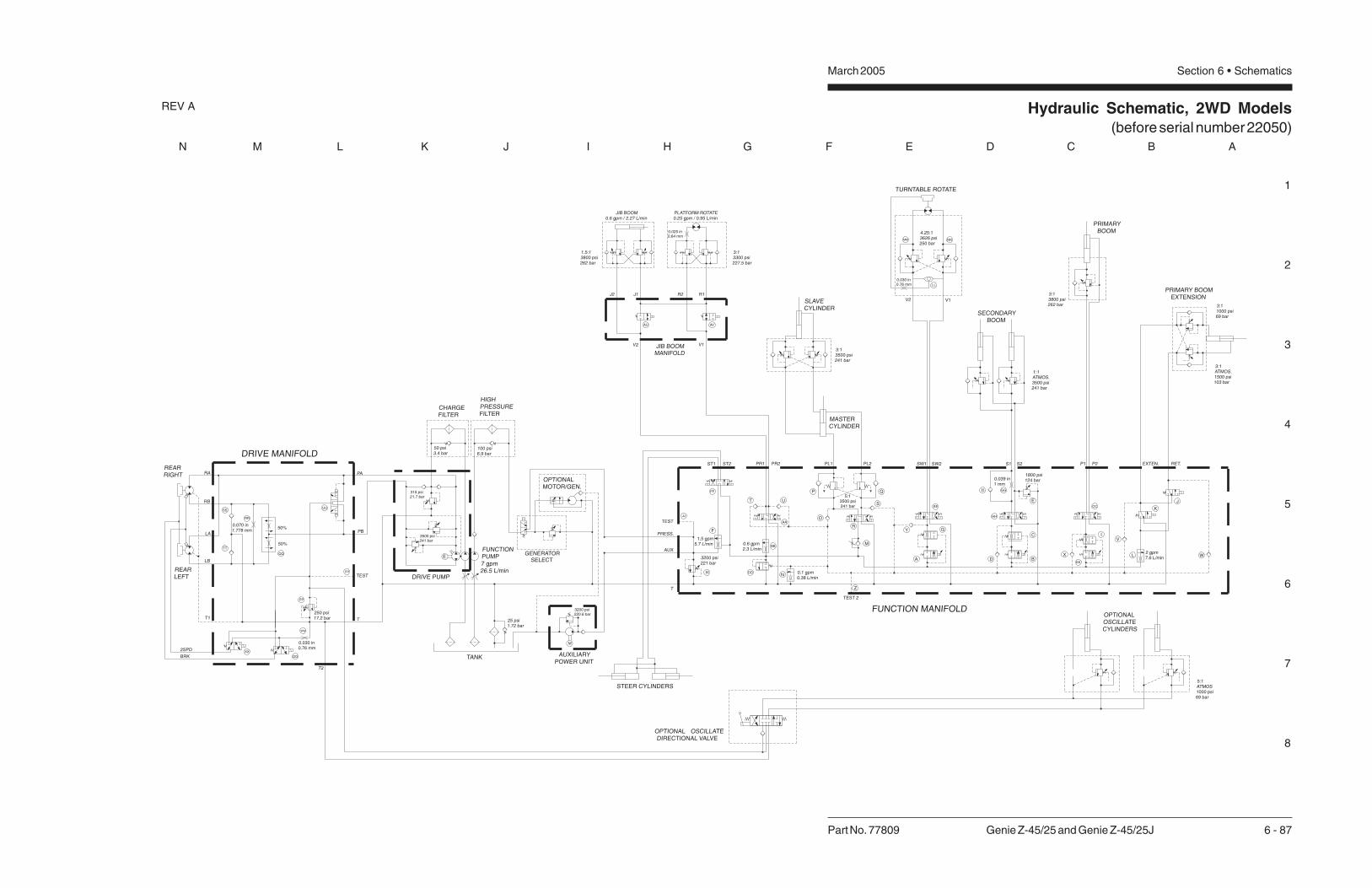
1
2
3
4
5
6
7
8
N M L K J I H G F E D C B A
Hydraulic Schematic, 2WD Models(before serial number 22050)
March 2005 Section 6 • Schematics
Part No. 77809 Genie Z-45/25 and Genie Z-45/25J 6 - 87
REV A
E
M
CHARGEFILTER
DRIVE PUMP
FUNCTIONPUMP7 gpm26.5 L/min
TANK AUXILIARYPOWER UNIT
SLAVECYLINDER
SECONDARYBOOM
PRIMARYBOOM
PRIMARY BOOMEXTENSION
TURNTABLE ROTATE
MASTERCYLINDER
FUNCTION MANIFOLD
REARLEFT
REARRIGHT
GENERATORSELECT
OPTIONALMOTOR/GEN.
DRIVE MANIFOLD
X
X
X
STEER CYLINDERS
LA
LB
RB
0.070 in1.778 mm
50%
50%
0.030 in0.76 mm
250 psi17.2 bar
TEST
PB
RA PA
315 psi21.7 bar
50 psi3.4 bar
3500 psi241 bar
3:13500 psi241 bar
V2
0.030 in0.76 mm
TEST
1.5 gpm5.7 L/min
PR1 PR2 PL1 PL2
3200 psi221 bar
0.6 gpm2.3 L/min
0.1 gpm0.38 L/min
SW1 SW2 S1 S2 P1
1800 psi124 bar
2 gpm7.6 L/min
P2 EXTEN. RET.
TEST 2
2SPD
BRK
AUX
1.5:13800 psi262 bar
3:13300 psi227.5 bar
3200 psi220.6 bar
25 psi1.72 bar
V1
4.25:13626 psi250 bar
1:1ATMOS.3500 psi241 bar
3:11000 psi69 bar
3:13800 psi262 bar
OSCILLATEDIRECTIONAL VALVE
5:1ATMOS1000 psi69 bar
T2
T
OPTIONAL
OPTIONALOSCILLATECYLINDERS
0.039 in1 mm
V2
J1J2
V1
R1R2
JIB BOOMMANIFOLD
JIB BOOM0.6 gpm / 2.27 L/min
PLATFORM ROTATE0.25 gpm / 0.95 L/min
ST1 ST2
T
3:1ATMOS.1500 psi103 bar
0.025 in0.64 mm
5:13500 psi241 bar
HIGHPRESSUREFILTER
100 psi6.9 bar
PRESS.
T1
A
Y
Z
M
N
O
P Q
R
S
G
B
I
X
J
K
L W
V
D
C
E
F
T
AA
BB
FF
JJ
OO
PP
XX
UU
VV
WW
RR
SS
TT
EE
LL
MM NN
GG
HH
II
DD
CC
KK
U
H
AU AV

Hydraulic Schematic, 2WD Models(before serial number 22051)
March 2005 Section 6 • Schematics

1
2
3
4
5
6
7
8
N M L K J I H G F E D C B A
Hydraulic Schematic, 2WD Models(after serial number 22049)
March 2005 Section 6 • Schematics
Part No. 77809 Genie Z-45/25 and Genie Z-45/25J 6 - 88
REV B
X
LA
LB
RB
50%
50%
PB
RA PA
2SPD
BRK
T2
TT1
REARRIGHT
REARLEFT
DRIVE MANIFOLD
0.030 inch0.76 mm
0.070 inch1.78 mm
250 psi17.2 bar
E
M
CHARGEFILTER
DRIVE PUMP
FUNCTION PUMP7 gpm / 26.5 L/min
TANK AUXILIARYPOWER UNIT
FUNCTION MANIFOLD
GENERATOR SELECT
OPTIONALMOTOR/GEN
STEER CYLINDERS
JIB BOOM0.6 gpm / 2.27 L/min
MASTER CYLINDER
PLATFORM ROTATE0.25 gpm / 0.95 L/min
SLAVE CYLINDER
SECONDARY BOOMCYLINDERS
TURNTABLE ROTATE
PRIMARY BOOMEXTENSION
PRIMARY BOOM
3:13800 psi262 bar
4.5:1ATMOS.3500 psi241 bar
4.25:13625 psi250 bar
V2
0.030 inch0.76 mm
V1
315 psi21.7 bar
50 psi3.4 bar
100 psi6.9 bar
3500 psi241 bar
1.5:13800 psi262 bar
3:13300 psi228 bar
EXTEN RETRACT
5:1ATMOS
1000 psi / 69 bar
ST1 ST2 PR1 PR2 PL1 PL2 SW1 SW2 S1 S2 P1 P2
AUX
T
TP2
25 psi1.7 bar
3200 psi220.6 bar
OSCILLATECYLINDERS(OPTION)
3:13500 psi241 bar
TP1
0.025 inch0.64 mm
3:11000 psi69 bar
3:1ATMOS.1500 psi103 bar
HIGHPRESSURE
FILTER
PRESS
T1/GEN
1.5 gpm5.7 L/min
0.4 gpm1.5 L/min
3200 psi220.6 bar (set at 7 gpm /26.5 L/min at TP1)
2500 psi / 172 bar(set at 0.6 gpm /
2.27 L/min at TP2)
0.037 inch0.9 mm
2100 psi144.8 bar(set at 2.5 gpm /9.5 L/min at TP2)
J1 J2 PR1PR2
V2 V1
OPTIONAL OSCILLATEDIRECTIONAL VALVE
JIB BOOM MANIFOLD(after serial number 22565)
V2
J1J2
V1
R1R2
JIB BOOM MANIFOLD(before serial number 22566)
AU AV
A
MN
F
O
P
JK
D
R
Q
E
Z
G
S
C
AA
AC
AB
LL
MMNN
AD
OO
WW
XX
UU
RR
SS
TT
PP
H
Y
W X
U
V
T
L
I
B
Orifice removedafter serial number 22449

Hydraulic Schematic, 2WD Models(after serial number 22050)
March 2005 Section 6 • Schematics

1
2
3
4
5
6
7
8
N M L K J I H G F E D C B A
Hydraulic Schematic, 4WD Models(before serial number 22050)
March 2005 Section 6 • Schematics
Part No. 77809 Genie Z-45/25 and Genie Z-45/25J 6 - 89
REV A
E
M
CHARGEFILTER
DRIVE PUMP
FUNCTION PUMP7 gpm / 26.5 L/min
TANK
FUNCTION MANIFOLD
REARLEFT
REARRIGHT
FRONTLEFT
FRONTRIGHT
GENERATOR SELECT
OPTIONALMOTOR/GEN.
DRIVE MANIFOLD
X
X
OPTIONAL OSCILLATEDIRECTIONAL VALVE
STEER CYLINDERS
RB
X
JIB BOOM0.6 gpm / 2.3 L/min
JIB BOOMMANIFOLD
MASTERCYLINDER
PLATFORM ROTATE0.25 gpm / 0.95 L/min
SLAVECYLINDER
SECONDARYBOOM
TURNTABLE ROTATE
PRIMARY BOOMEXTENSION
PRIMARY BOOM
3:1ATMOS.1500 psi103 bar
3:13800 psi262 bar
1:1ATMOS.3500 psi241 bar
4.25:13626 psi250 bar
V2
0.030 in0.762 mm
V1
315 psi21.7 bar
50 psi3.4 bar
B
A
RFB
RFA
LFB
LFA
TEST
T2
T
TANK
67% 33%
0.052 in1.32 mm
250 psi17.2 bar
0.030 in0.76 mm
50%
50%
RA
LB
LA
BRK
2SPD
50%
50%
3500 psi241 bar
1.5:13800 psi262 bar
J2 J1 R2 R1
V2 V1
3:13300 psi227.5 bar
2 gpm7.6 L/min
EXTEN. RETRACT
5:1ATMOS1000 psi69 bar
ST1 ST2 PR1 PR2 PL1 PL2 SW1 SW2 S1 S2 P1 P2
TEST
AUX
T
3200 psi221 bar
0.6 gpm2.3 L/min
0.1 gpm0.38 L/min
TEST 2
1.5 gpm5.7 L/min
25 psi1.72 bar
3200 psi220.6 bar
2 gpm7.6 L/min
1 gpm3.8 L/min
0.039 in1 mm
OPTIONALOSCILLATECYLINDERS
3:13500 psi241 bar
T1
1800 psi124 bar
0.025 in0.64 mm
3:11000 psi69 bar
5:13500 psi241 bar
100 psi6.9 bar
HIGHPRESSUREFILTER
PRESS.
0.025 in0.64 mm
AUXILIARYPOWER UNIT
A
Y
Z
M
N
O
P Q
R
S
G
B
I
X
J
K
L WVD
C
E
F
T
AA
BB
FF
AU AV
JJ
AB
AS
AT
AG
AE
AN
AF
AH
AI
AL
AM
AK
AJ
AC AD
AO
AQ
AR
AP
EE
LL
MM NN
GG
HH
II
DD
CC
KK
U
H

Hydraulic Schematic, 4WD Models(before serial number 22340)
March 2005 Section 6 • Schematics

1
2
3
4
5
6
7
8
N M L K J I H G F E D C B A
Hydraulic Schematic, 4WD Models(after serial number 22049)
March 2005 Section 6 • Schematics
Part No. 77809 Genie Z-45/25 and Genie Z-45/25J 6 - 90
REV B
E
M
CHARGEFILTER
DRIVE PUMP
FUNCTION PUMP7 gpm / 26.5 L/min
TANK AUXILIARYPOWER UNIT
FUNCTION MANIFOLD
GENERATOR SELECT
OPTIONALMOTOR/GEN
STEER CYLINDERS
JIB BOOM0.6 gpm / 2.27 L/min
MASTER CYLINDER
PLATFORM ROTATE0.25 gpm / 0.95 L/min
SLAVE CYLINDER
SECONDARY BOOMCYLINDERS
TURNTABLE ROTATE
PRIMARY BOOMEXTENSION
PRIMARY BOOM
3:13800 psi262 bar
4.5:1ATMOS.3500 psi241 bar
4.25:13625 psi250 bar
V2
0.030 inch0.76 mm
BA
V1
315 psi21.7 bar
50 psi3.4 bar
100 psi6.9 bar
3500 psi241 bar
1.5:13800 psi262 bar
3:13300 psi228 bar
Orifice removedafter serial number 22449
EXTEN RETRACT
5:1ATMOS
1000 psi / 69 bar
ST1 ST2 PR1 PR2 PL1 PL2 SW1 SW2 S1 S2 P1 P2
AUX
T
TP2
25 psi1.7 bar
3200 psi220.6 bar
OSCILLATECYLINDERS(OPTION)
3:13500 psi241 bar
TP1
0.025 inch0.64 mm
3:11000 psi69 bar
3:1ATMOS.1500 psi103 bar
HIGHPRESSURE
FILTER
PRESS
T1/GEN
1.5 gpm5.7 L/min
0.4 gpm1.5 L/min
3200 psi220.6 bar (set at 7 gpm /26.5 L/min at TP1)
2500 psi / 172 bar(set at 0.6 gpm /
2.27 L/min at TP2)
0.037 inch0.9 mm
2100 psi144.8 bar(set at 2.5 gpm /9.5 L/min at TP2)
0.025 inch0.64 mm
1 gpm3.8 L/min
2 gpm7.6 L/min
50%
50%
2SPD
BRK
LA
LB
RA
50%
50%
0.030 inch0.76 mm
250 psi17.2 bar
0.052 inch1.3 mm
33%67%
TANK
T
T2
TEST
LFA
LFB
RFA
RFB
A
BRB
X
DRIVE MANIFOLD
FRONTRIGHT
FRONTLEFT
REARRIGHT
REARLEFT
J1 J2 PR2 PR1
V2 V1
R
OPTIONAL OSCILLATEDIRECTIONAL VALVE
JIB BOOM MANIFOLD(after serial number 22565)
V2
J1J2
V1
R1R2
JIB BOOM MANIFOLD(before serial number 22566)
AU AV
AQ
AO
AT
AB
AC
AE
AN
AS
AP
AL
AM
AIAK
AJ
AH
AD
AR
AG
A
MN
F
O
P
JK
D
R
Q
E
Z
G
S
C
AA
AC
AB
AD
H
Y
W X
U
V
T
L
I
B
LL
MMNN

Hydraulic Schematic, 4WD Models(after serial number 22339)
March 2005 Section 6 • Schematics

Dis
trib
ute
d B
y:
California Proposition 65
WARNINGWARNINGThe exhaust from this product contains chemicals
known to the State of California to cause cancer,
birth defects or other reproductive harm.
Genie North AmericaPhone 425.881.1800
Toll Free USA and Canada
800.536.1800
Fax 425.883.3475
Genie Australia Pty Ltd.Phone +61 7 3375 1660
Fax +61 7 3375 1002
Genie ChinaPhone +86 21 53852570
Fax +86 21 53852569
Genie MalaysiaPhone +65 98 480 775
Fax +65 67 533 544
Genie JapanPhone +81 3 3453 6082
Fax +81 3 3453 6083
Genie KoreaPhone +82 25 587 267
Fax +82 25 583 910
Genie BrasilPhone +55 11 41 665 755
Fax +55 11 41 665 754
Genie HollandPhone +31 183 581 102
Fax +31 183 581 566
Genie ScandinaviaPhone +46 31 575100
Fax +46 31 579020
Genie FrancePhone +33 (0)2 37 26 09 99
Fax +33 (0)2 37 26 09 98
Genie IbericaPhone +34 93 579 5042
Fax +34 93 579 5059
Genie GermanyPhone +49 (0)4202 88520
Fax +49 (0)4202 8852-20
Genie U.K.Phone +44 (0)1476 584333
Fax +44 (0)1476 584334
Genie Mexico CityPhone +52 55 5666 5242
Fax +52 55 5666 3241