7750 sr os router configuration guide 12 - nokia...
TRANSCRIPT

Alcatel-LucentService Router | Release 12.0 R47 7 5 0 S R - O S R o u t e r C o n f i g u r a t i o n G u i d e
93-0073-11-02 Edition 1
Alcatel, Lucent, Alcatel-Lucent and the Alcatel-Lucent logo are trademarks of Alcatel-Lucent. All other trademarks are the property of their respective owners. The information presented is subject to change without notice. Alcatel-Lucent assumes no responsibility for inaccuracies contained herein. Copyright © 2014 Alcatel-LucentAll Rights Reserved.

This document is protected by copyright. Except as specifically permitted herein, no portion of the provided information can be reproduced in any form, or by any means, without prior written permission from Alcatel-Lucent.Alcatel, Lucent, Alcatel-Lucent and the Alcatel-Lucent logo are trademarks of Alcatel-Lucent. All other trademarks are the property of their respective owners.The information presented is subject to change without notice.Alcatel-Lucent assumes no responsibility for inaccuracies contained herein.
Copyright 2014 Alcatel-Lucent. All rights reserved.

Table of Contents
Getting StartedAlcatel-Lucent 7750 SR-Series Router Configuration Process . . . . . . . . . . . . . . . . . . . . . . . . . . . . . . . . .17
IP Router ConfigurationConfiguring IP Router Parameters . . . . . . . . . . . . . . . . . . . . . . . . . . . . . . . . . . . . . . . . . . . . . . . . . . . . . . .20
Interfaces. . . . . . . . . . . . . . . . . . . . . . . . . . . . . . . . . . . . . . . . . . . . . . . . . . . . . . . . . . . . . . . . . . . . . . . .20Network Interface . . . . . . . . . . . . . . . . . . . . . . . . . . . . . . . . . . . . . . . . . . . . . . . . . . . . . . . . . . . . . . .20Network Domains . . . . . . . . . . . . . . . . . . . . . . . . . . . . . . . . . . . . . . . . . . . . . . . . . . . . . . . . . . . . . . .21System Interface . . . . . . . . . . . . . . . . . . . . . . . . . . . . . . . . . . . . . . . . . . . . . . . . . . . . . . . . . . . . . . .22Unicast Reverse Path Forwarding Check (uRPF) . . . . . . . . . . . . . . . . . . . . . . . . . . . . . . . . . . . . . .23Creating an IP Address Range. . . . . . . . . . . . . . . . . . . . . . . . . . . . . . . . . . . . . . . . . . . . . . . . . . . . .24QoS Policy Propagation Using BGP (QPPB) . . . . . . . . . . . . . . . . . . . . . . . . . . . . . . . . . . . . . . . . . .25QPPB . . . . . . . . . . . . . . . . . . . . . . . . . . . . . . . . . . . . . . . . . . . . . . . . . . . . . . . . . . . . . . . . . . . . . . . .28QPPB and GRT Lookup . . . . . . . . . . . . . . . . . . . . . . . . . . . . . . . . . . . . . . . . . . . . . . . . . . . . . . . . . .33
Router ID . . . . . . . . . . . . . . . . . . . . . . . . . . . . . . . . . . . . . . . . . . . . . . . . . . . . . . . . . . . . . . . . . . . . . . . .36Autonomous Systems (AS) . . . . . . . . . . . . . . . . . . . . . . . . . . . . . . . . . . . . . . . . . . . . . . . . . . . . . . . . . .37Confederations . . . . . . . . . . . . . . . . . . . . . . . . . . . . . . . . . . . . . . . . . . . . . . . . . . . . . . . . . . . . . . . . . . .38Proxy ARP . . . . . . . . . . . . . . . . . . . . . . . . . . . . . . . . . . . . . . . . . . . . . . . . . . . . . . . . . . . . . . . . . . . . . . .40Exporting an Inactive BGP Route from a VPRN . . . . . . . . . . . . . . . . . . . . . . . . . . . . . . . . . . . . . . . . . .41DHCP Relay . . . . . . . . . . . . . . . . . . . . . . . . . . . . . . . . . . . . . . . . . . . . . . . . . . . . . . . . . . . . . . . . . . . . .42Internet Protocol Versions . . . . . . . . . . . . . . . . . . . . . . . . . . . . . . . . . . . . . . . . . . . . . . . . . . . . . . . . . . .43
IPv6 Address Format . . . . . . . . . . . . . . . . . . . . . . . . . . . . . . . . . . . . . . . . . . . . . . . . . . . . . . . . . . . .44IPv6 Applications . . . . . . . . . . . . . . . . . . . . . . . . . . . . . . . . . . . . . . . . . . . . . . . . . . . . . . . . . . . . . . .46DNS . . . . . . . . . . . . . . . . . . . . . . . . . . . . . . . . . . . . . . . . . . . . . . . . . . . . . . . . . . . . . . . . . . . . . . . . .48IPv6 Provider Edge Router over MPLS (6PE) . . . . . . . . . . . . . . . . . . . . . . . . . . . . . . . . . . . . . . . . .49
Bi-directional Forwarding Detection. . . . . . . . . . . . . . . . . . . . . . . . . . . . . . . . . . . . . . . . . . . . . . . . . . . .51BFD Control Packet . . . . . . . . . . . . . . . . . . . . . . . . . . . . . . . . . . . . . . . . . . . . . . . . . . . . . . . . . . . . .51Control Packet Format . . . . . . . . . . . . . . . . . . . . . . . . . . . . . . . . . . . . . . . . . . . . . . . . . . . . . . . . . . .52BFD for RSVP-TE . . . . . . . . . . . . . . . . . . . . . . . . . . . . . . . . . . . . . . . . . . . . . . . . . . . . . . . . . . . . . .54Echo Support . . . . . . . . . . . . . . . . . . . . . . . . . . . . . . . . . . . . . . . . . . . . . . . . . . . . . . . . . . . . . . . . . .55BFD Support for BGP. . . . . . . . . . . . . . . . . . . . . . . . . . . . . . . . . . . . . . . . . . . . . . . . . . . . . . . . . . . .56Centralized BFD . . . . . . . . . . . . . . . . . . . . . . . . . . . . . . . . . . . . . . . . . . . . . . . . . . . . . . . . . . . . . . . .56Aggregate Next Hop. . . . . . . . . . . . . . . . . . . . . . . . . . . . . . . . . . . . . . . . . . . . . . . . . . . . . . . . . . . . .59Invalidate Next-Hop Based on ARP/Neighbor Cache State. . . . . . . . . . . . . . . . . . . . . . . . . . . . . . .59
Process Overview. . . . . . . . . . . . . . . . . . . . . . . . . . . . . . . . . . . . . . . . . . . . . . . . . . . . . . . . . . . . . . . . . . . .61Configuration Notes . . . . . . . . . . . . . . . . . . . . . . . . . . . . . . . . . . . . . . . . . . . . . . . . . . . . . . . . . . . . . . . . . .62Configuring an IP Router with CLI . . . . . . . . . . . . . . . . . . . . . . . . . . . . . . . . . . . . . . . . . . . . . . . . . . . . . . .63Router Configuration Overview. . . . . . . . . . . . . . . . . . . . . . . . . . . . . . . . . . . . . . . . . . . . . . . . . . . . . . . . . .64
System Interface . . . . . . . . . . . . . . . . . . . . . . . . . . . . . . . . . . . . . . . . . . . . . . . . . . . . . . . . . . . . . . . . . .64Network Interface . . . . . . . . . . . . . . . . . . . . . . . . . . . . . . . . . . . . . . . . . . . . . . . . . . . . . . . . . . . . . . . . .64
Basic Configuration. . . . . . . . . . . . . . . . . . . . . . . . . . . . . . . . . . . . . . . . . . . . . . . . . . . . . . . . . . . . . . . . . . .65Common Configuration Tasks . . . . . . . . . . . . . . . . . . . . . . . . . . . . . . . . . . . . . . . . . . . . . . . . . . . . . . . . . .66
Configuring a System Name . . . . . . . . . . . . . . . . . . . . . . . . . . . . . . . . . . . . . . . . . . . . . . . . . . . . . . . . .66Configuring Interfaces . . . . . . . . . . . . . . . . . . . . . . . . . . . . . . . . . . . . . . . . . . . . . . . . . . . . . . . . . . . . . .67
Configuring a System Interface . . . . . . . . . . . . . . . . . . . . . . . . . . . . . . . . . . . . . . . . . . . . . . . . . . . .67
7750 SR OS Router Configuration Guide Page 3

Table of Contents
Configuring a Network Interface. . . . . . . . . . . . . . . . . . . . . . . . . . . . . . . . . . . . . . . . . . . . . . . . . . . .67Configuring IPv6 Parameters . . . . . . . . . . . . . . . . . . . . . . . . . . . . . . . . . . . . . . . . . . . . . . . . . . . . . .69Configuring IPv6 Over IPv4 Parameters . . . . . . . . . . . . . . . . . . . . . . . . . . . . . . . . . . . . . . . . . . . . .70Tunnel Ingress Node . . . . . . . . . . . . . . . . . . . . . . . . . . . . . . . . . . . . . . . . . . . . . . . . . . . . . . . . . . . .70Tunnel Egress Node. . . . . . . . . . . . . . . . . . . . . . . . . . . . . . . . . . . . . . . . . . . . . . . . . . . . . . . . . . . . .75Router Advertisement. . . . . . . . . . . . . . . . . . . . . . . . . . . . . . . . . . . . . . . . . . . . . . . . . . . . . . . . . . . .79Configuring IPv6 Parameters . . . . . . . . . . . . . . . . . . . . . . . . . . . . . . . . . . . . . . . . . . . . . . . . . . . . . .80Configuring Proxy ARP . . . . . . . . . . . . . . . . . . . . . . . . . . . . . . . . . . . . . . . . . . . . . . . . . . . . . . . . . .82Creating an IP Address Range. . . . . . . . . . . . . . . . . . . . . . . . . . . . . . . . . . . . . . . . . . . . . . . . . . . . .84Configuring an LDP Shortcut . . . . . . . . . . . . . . . . . . . . . . . . . . . . . . . . . . . . . . . . . . . . . . . . . . . . . .84
Deriving the Router ID . . . . . . . . . . . . . . . . . . . . . . . . . . . . . . . . . . . . . . . . . . . . . . . . . . . . . . . . . . . . . .88Configuring a Confederation . . . . . . . . . . . . . . . . . . . . . . . . . . . . . . . . . . . . . . . . . . . . . . . . . . . . . . . . .89Configuring an Autonomous System . . . . . . . . . . . . . . . . . . . . . . . . . . . . . . . . . . . . . . . . . . . . . . . . . . .90Configuring Overload State on a Single SFM . . . . . . . . . . . . . . . . . . . . . . . . . . . . . . . . . . . . . . . . . . . .91
Service Management Tasks . . . . . . . . . . . . . . . . . . . . . . . . . . . . . . . . . . . . . . . . . . . . . . . . . . . . . . . . . . . .92Changing the System Name . . . . . . . . . . . . . . . . . . . . . . . . . . . . . . . . . . . . . . . . . . . . . . . . . . . . . . . . .92Modifying Interface Parameters. . . . . . . . . . . . . . . . . . . . . . . . . . . . . . . . . . . . . . . . . . . . . . . . . . . . . . .93Deleting a Logical IP Interface. . . . . . . . . . . . . . . . . . . . . . . . . . . . . . . . . . . . . . . . . . . . . . . . . . . . . . . .94
IP Router Command Reference . . . . . . . . . . . . . . . . . . . . . . . . . . . . . . . . . . . . . . . . . . . . . . . . . . . . . . . . .95Configuration Commands . . . . . . . . . . . . . . . . . . . . . . . . . . . . . . . . . . . . . . . . . . . . . . . . . . . . . . . . . .111
Generic Commands . . . . . . . . . . . . . . . . . . . . . . . . . . . . . . . . . . . . . . . . . . . . . . . . . . . . . . . . . . . .111Router Global Commands . . . . . . . . . . . . . . . . . . . . . . . . . . . . . . . . . . . . . . . . . . . . . . . . . . . . . . .112Router L2TP Commands . . . . . . . . . . . . . . . . . . . . . . . . . . . . . . . . . . . . . . . . . . . . . . . . . . . . . . . .140Router Interface Commands . . . . . . . . . . . . . . . . . . . . . . . . . . . . . . . . . . . . . . . . . . . . . . . . . . . . .161Router Advertisement Commands . . . . . . . . . . . . . . . . . . . . . . . . . . . . . . . . . . . . . . . . . . . . . . . . .205
Show Commands . . . . . . . . . . . . . . . . . . . . . . . . . . . . . . . . . . . . . . . . . . . . . . . . . . . . . . . . . . . . . . . .211L2TP Show Commands . . . . . . . . . . . . . . . . . . . . . . . . . . . . . . . . . . . . . . . . . . . . . . . . . . . . . . . . .282
Clear Commands. . . . . . . . . . . . . . . . . . . . . . . . . . . . . . . . . . . . . . . . . . . . . . . . . . . . . . . . . . . . . . . . .301Debug Commands. . . . . . . . . . . . . . . . . . . . . . . . . . . . . . . . . . . . . . . . . . . . . . . . . . . . . . . . . . . . . . . .307
VRRPVRRP Overview . . . . . . . . . . . . . . . . . . . . . . . . . . . . . . . . . . . . . . . . . . . . . . . . . . . . . . . . . . . . . . . . . . . .314VRRP Components . . . . . . . . . . . . . . . . . . . . . . . . . . . . . . . . . . . . . . . . . . . . . . . . . . . . . . . . . . . . . . . . .315
Virtual Router. . . . . . . . . . . . . . . . . . . . . . . . . . . . . . . . . . . . . . . . . . . . . . . . . . . . . . . . . . . . . . . . . . . .315IP Address Owner . . . . . . . . . . . . . . . . . . . . . . . . . . . . . . . . . . . . . . . . . . . . . . . . . . . . . . . . . . . . . . . .315Primary and Secondary IP Addresses. . . . . . . . . . . . . . . . . . . . . . . . . . . . . . . . . . . . . . . . . . . . . . . . .316Virtual Router Master. . . . . . . . . . . . . . . . . . . . . . . . . . . . . . . . . . . . . . . . . . . . . . . . . . . . . . . . . . . . . .316Virtual Router Backup . . . . . . . . . . . . . . . . . . . . . . . . . . . . . . . . . . . . . . . . . . . . . . . . . . . . . . . . . . . . .317Owner and Non-Owner VRRP. . . . . . . . . . . . . . . . . . . . . . . . . . . . . . . . . . . . . . . . . . . . . . . . . . . . . . .317Configurable Parameters. . . . . . . . . . . . . . . . . . . . . . . . . . . . . . . . . . . . . . . . . . . . . . . . . . . . . . . . . . .318
Virtual Router ID (VRID). . . . . . . . . . . . . . . . . . . . . . . . . . . . . . . . . . . . . . . . . . . . . . . . . . . . . . . . .318Priority . . . . . . . . . . . . . . . . . . . . . . . . . . . . . . . . . . . . . . . . . . . . . . . . . . . . . . . . . . . . . . . . . . . . . .318IP Addresses . . . . . . . . . . . . . . . . . . . . . . . . . . . . . . . . . . . . . . . . . . . . . . . . . . . . . . . . . . . . . . . . .319Message Interval and Master Inheritance . . . . . . . . . . . . . . . . . . . . . . . . . . . . . . . . . . . . . . . . . . .320Skew Time . . . . . . . . . . . . . . . . . . . . . . . . . . . . . . . . . . . . . . . . . . . . . . . . . . . . . . . . . . . . . . . . . . .320Master Down Interval . . . . . . . . . . . . . . . . . . . . . . . . . . . . . . . . . . . . . . . . . . . . . . . . . . . . . . . . . . .321Preempt Mode . . . . . . . . . . . . . . . . . . . . . . . . . . . . . . . . . . . . . . . . . . . . . . . . . . . . . . . . . . . . . . . .321VRRP Message Authentication . . . . . . . . . . . . . . . . . . . . . . . . . . . . . . . . . . . . . . . . . . . . . . . . . . .322Authentication Data . . . . . . . . . . . . . . . . . . . . . . . . . . . . . . . . . . . . . . . . . . . . . . . . . . . . . . . . . . . .324
Page 4 7750 SR OS Router Configuration Guide

Table of Contents
Virtual MAC Address . . . . . . . . . . . . . . . . . . . . . . . . . . . . . . . . . . . . . . . . . . . . . . . . . . . . . . . . . . .324VRRP Advertisement Message IP Address List Verification . . . . . . . . . . . . . . . . . . . . . . . . . . . . .324Inherit Master VRRP Router’s Advertisement Interval Timer . . . . . . . . . . . . . . . . . . . . . . . . . . . . .325IPv6 Virtual Router Instance Operationally Up. . . . . . . . . . . . . . . . . . . . . . . . . . . . . . . . . . . . . . . .325Policies . . . . . . . . . . . . . . . . . . . . . . . . . . . . . . . . . . . . . . . . . . . . . . . . . . . . . . . . . . . . . . . . . . . . . .325
VRRP Priority Control Policies . . . . . . . . . . . . . . . . . . . . . . . . . . . . . . . . . . . . . . . . . . . . . . . . . . . . . . . . .326VRRP Virtual Router Policy Constraints . . . . . . . . . . . . . . . . . . . . . . . . . . . . . . . . . . . . . . . . . . . . . . .326VRRP Virtual Router Instance Base Priority . . . . . . . . . . . . . . . . . . . . . . . . . . . . . . . . . . . . . . . . . . . .326VRRP Priority Control Policy Delta In-Use Priority Limit . . . . . . . . . . . . . . . . . . . . . . . . . . . . . . . . . . .327VRRP Priority Control Policy Priority Events . . . . . . . . . . . . . . . . . . . . . . . . . . . . . . . . . . . . . . . . . . . .328
Priority Event Hold-Set Timers . . . . . . . . . . . . . . . . . . . . . . . . . . . . . . . . . . . . . . . . . . . . . . . . . . . .328Port Down Priority Event . . . . . . . . . . . . . . . . . . . . . . . . . . . . . . . . . . . . . . . . . . . . . . . . . . . . . . . .329LAG Degrade Priority Event . . . . . . . . . . . . . . . . . . . . . . . . . . . . . . . . . . . . . . . . . . . . . . . . . . . . . .329Host Unreachable Priority Event . . . . . . . . . . . . . . . . . . . . . . . . . . . . . . . . . . . . . . . . . . . . . . . . . .332Route Unknown Priority Event . . . . . . . . . . . . . . . . . . . . . . . . . . . . . . . . . . . . . . . . . . . . . . . . . . . .332
VRRP Non-Owner Accessibility . . . . . . . . . . . . . . . . . . . . . . . . . . . . . . . . . . . . . . . . . . . . . . . . . . . . . . . .334Non-Owner Access Ping Reply . . . . . . . . . . . . . . . . . . . . . . . . . . . . . . . . . . . . . . . . . . . . . . . . . . . . . .334Non-Owner Access Telnet. . . . . . . . . . . . . . . . . . . . . . . . . . . . . . . . . . . . . . . . . . . . . . . . . . . . . . . . . .334Non-Owner Access SSH . . . . . . . . . . . . . . . . . . . . . . . . . . . . . . . . . . . . . . . . . . . . . . . . . . . . . . . . . . .335
VRRP Configuration Process Overview . . . . . . . . . . . . . . . . . . . . . . . . . . . . . . . . . . . . . . . . . . . . . . . . . .336Configuration Notes . . . . . . . . . . . . . . . . . . . . . . . . . . . . . . . . . . . . . . . . . . . . . . . . . . . . . . . . . . . . . . . . .337
General . . . . . . . . . . . . . . . . . . . . . . . . . . . . . . . . . . . . . . . . . . . . . . . . . . . . . . . . . . . . . . . . . . . . . . . .337Configuring VRRP with CLI . . . . . . . . . . . . . . . . . . . . . . . . . . . . . . . . . . . . . . . . . . . . . . . . . . . . . . . . . . .339VRRP Configuration Overview . . . . . . . . . . . . . . . . . . . . . . . . . . . . . . . . . . . . . . . . . . . . . . . . . . . . . . . . .340
Preconfiguration Requirements . . . . . . . . . . . . . . . . . . . . . . . . . . . . . . . . . . . . . . . . . . . . . . . . . . . . . .340Basic VRRP Configurations . . . . . . . . . . . . . . . . . . . . . . . . . . . . . . . . . . . . . . . . . . . . . . . . . . . . . . . . . . .341
VRRP Policy . . . . . . . . . . . . . . . . . . . . . . . . . . . . . . . . . . . . . . . . . . . . . . . . . . . . . . . . . . . . . . . . . . . .341VRRP IES Service Parameters . . . . . . . . . . . . . . . . . . . . . . . . . . . . . . . . . . . . . . . . . . . . . . . . . . . . . .342
Configure VRRP for IPv6 . . . . . . . . . . . . . . . . . . . . . . . . . . . . . . . . . . . . . . . . . . . . . . . . . . . . . . . .343VRRP Router Interface Parameters . . . . . . . . . . . . . . . . . . . . . . . . . . . . . . . . . . . . . . . . . . . . . . . . . .344
Common Configuration Tasks . . . . . . . . . . . . . . . . . . . . . . . . . . . . . . . . . . . . . . . . . . . . . . . . . . . . . . . . .345Creating Interface Parameters . . . . . . . . . . . . . . . . . . . . . . . . . . . . . . . . . . . . . . . . . . . . . . . . . . . . . .346
Configuring VRRP Policy Components . . . . . . . . . . . . . . . . . . . . . . . . . . . . . . . . . . . . . . . . . . . . . . . . . .347Configuring Service VRRP Parameters. . . . . . . . . . . . . . . . . . . . . . . . . . . . . . . . . . . . . . . . . . . . . . . .348
Non-Owner VRRP Example . . . . . . . . . . . . . . . . . . . . . . . . . . . . . . . . . . . . . . . . . . . . . . . . . . . . . .348Owner Service VRRP . . . . . . . . . . . . . . . . . . . . . . . . . . . . . . . . . . . . . . . . . . . . . . . . . . . . . . . . . .349
Configuring Router Interface VRRP Parameters. . . . . . . . . . . . . . . . . . . . . . . . . . . . . . . . . . . . . . . . .350Router Interface VRRP Non-Owner . . . . . . . . . . . . . . . . . . . . . . . . . . . . . . . . . . . . . . . . . . . . . . .350Router Interface VRRP Owner . . . . . . . . . . . . . . . . . . . . . . . . . . . . . . . . . . . . . . . . . . . . . . . . . . .351
VRRP Configuration Management Tasks. . . . . . . . . . . . . . . . . . . . . . . . . . . . . . . . . . . . . . . . . . . . . . . . .352Modifying a VRRP Policy. . . . . . . . . . . . . . . . . . . . . . . . . . . . . . . . . . . . . . . . . . . . . . . . . . . . . . . . . . .352
Deleting a VRRP Policy . . . . . . . . . . . . . . . . . . . . . . . . . . . . . . . . . . . . . . . . . . . . . . . . . . . . . . . . .353Modifying Service and Interface VRRP Parameters . . . . . . . . . . . . . . . . . . . . . . . . . . . . . . . . . . . . . .354
Modifying Non-Owner Parameters . . . . . . . . . . . . . . . . . . . . . . . . . . . . . . . . . . . . . . . . . . . . . . . . .354Modifying Owner Parameters. . . . . . . . . . . . . . . . . . . . . . . . . . . . . . . . . . . . . . . . . . . . . . . . . . . . .354Deleting VRRP on an Interface or Service . . . . . . . . . . . . . . . . . . . . . . . . . . . . . . . . . . . . . . . . . . .354
VRRP Command Reference. . . . . . . . . . . . . . . . . . . . . . . . . . . . . . . . . . . . . . . . . . . . . . . . . . . . . . . . . . .355Configuration Commands . . . . . . . . . . . . . . . . . . . . . . . . . . . . . . . . . . . . . . . . . . . . . . . . . . . . . . . . . .363
Interface Configuration Commands . . . . . . . . . . . . . . . . . . . . . . . . . . . . . . . . . . . . . . . . . . . . . . . .363
7750 SR OS Router Configuration Guide Page 5

Table of Contents
Priority Policy Commands . . . . . . . . . . . . . . . . . . . . . . . . . . . . . . . . . . . . . . . . . . . . . . . . . . . . . . .381Priority Policy Event Commands . . . . . . . . . . . . . . . . . . . . . . . . . . . . . . . . . . . . . . . . . . . . . . . . . .384Priority Policy Port Down Event Commands . . . . . . . . . . . . . . . . . . . . . . . . . . . . . . . . . . . . . . . . .387Priority Policy LAG Events Commands . . . . . . . . . . . . . . . . . . . . . . . . . . . . . . . . . . . . . . . . . . . . .389Priority Policy Host Unreachable Event Commands . . . . . . . . . . . . . . . . . . . . . . . . . . . . . . . . . . .392Priority Policy Route Unknown Event Commands . . . . . . . . . . . . . . . . . . . . . . . . . . . . . . . . . . . . .397
Show Commands . . . . . . . . . . . . . . . . . . . . . . . . . . . . . . . . . . . . . . . . . . . . . . . . . . . . . . . . . . . . . . . .403Monitor Commands . . . . . . . . . . . . . . . . . . . . . . . . . . . . . . . . . . . . . . . . . . . . . . . . . . . . . . . . . . . . . . .416Clear Commands. . . . . . . . . . . . . . . . . . . . . . . . . . . . . . . . . . . . . . . . . . . . . . . . . . . . . . . . . . . . . . . . .418
VRRP Debug Commands. . . . . . . . . . . . . . . . . . . . . . . . . . . . . . . . . . . . . . . . . . . . . . . . . . . . . . . . . . . . .420
Filter PoliciesACL Filter Policy Overview . . . . . . . . . . . . . . . . . . . . . . . . . . . . . . . . . . . . . . . . . . . . . . . . . . . . . . . . . . . .422
Filter Policy Basics . . . . . . . . . . . . . . . . . . . . . . . . . . . . . . . . . . . . . . . . . . . . . . . . . . . . . . . . . . . . . . .423Filter Policy Packet Match Criteria . . . . . . . . . . . . . . . . . . . . . . . . . . . . . . . . . . . . . . . . . . . . . . . . .423IPv4/IPv6 Filter Policy Entry Match Criteria . . . . . . . . . . . . . . . . . . . . . . . . . . . . . . . . . . . . . . . . . .423MAC Filter Policy Entry Match Criteria . . . . . . . . . . . . . . . . . . . . . . . . . . . . . . . . . . . . . . . . . . . . . .426Filter Policy Actions . . . . . . . . . . . . . . . . . . . . . . . . . . . . . . . . . . . . . . . . . . . . . . . . . . . . . . . . . . . .428Filter Policy Statistics . . . . . . . . . . . . . . . . . . . . . . . . . . . . . . . . . . . . . . . . . . . . . . . . . . . . . . . . . . .429Filter Policy Logging . . . . . . . . . . . . . . . . . . . . . . . . . . . . . . . . . . . . . . . . . . . . . . . . . . . . . . . . . . . .431Filter Policy cflowd Sampling . . . . . . . . . . . . . . . . . . . . . . . . . . . . . . . . . . . . . . . . . . . . . . . . . . . . .431Filter policy management . . . . . . . . . . . . . . . . . . . . . . . . . . . . . . . . . . . . . . . . . . . . . . . . . . . . . . . .432
Filter Policy Advanced Topics . . . . . . . . . . . . . . . . . . . . . . . . . . . . . . . . . . . . . . . . . . . . . . . . . . . . . . .434Match-list for Filter Policies. . . . . . . . . . . . . . . . . . . . . . . . . . . . . . . . . . . . . . . . . . . . . . . . . . . . . . .434Embedded Filters . . . . . . . . . . . . . . . . . . . . . . . . . . . . . . . . . . . . . . . . . . . . . . . . . . . . . . . . . . . . . .437ISID MAC Filters. . . . . . . . . . . . . . . . . . . . . . . . . . . . . . . . . . . . . . . . . . . . . . . . . . . . . . . . . . . . . . .438VID MAC filters . . . . . . . . . . . . . . . . . . . . . . . . . . . . . . . . . . . . . . . . . . . . . . . . . . . . . . . . . . . . . . . .439Redirect Policies. . . . . . . . . . . . . . . . . . . . . . . . . . . . . . . . . . . . . . . . . . . . . . . . . . . . . . . . . . . . . . .443HTTP-redirect (Captive Portal) . . . . . . . . . . . . . . . . . . . . . . . . . . . . . . . . . . . . . . . . . . . . . . . . . . . .444Filter Policies and Dynamic, Policy-Driven Interfaces . . . . . . . . . . . . . . . . . . . . . . . . . . . . . . . . . .446
Configuring Filter Policies with CLI . . . . . . . . . . . . . . . . . . . . . . . . . . . . . . . . . . . . . . . . . . . . . . . . . . . . . .447Basic Configuration. . . . . . . . . . . . . . . . . . . . . . . . . . . . . . . . . . . . . . . . . . . . . . . . . . . . . . . . . . . . . . . . . .448Common Configuration Tasks . . . . . . . . . . . . . . . . . . . . . . . . . . . . . . . . . . . . . . . . . . . . . . . . . . . . . . . . .449
Creating an IP Filter Policy . . . . . . . . . . . . . . . . . . . . . . . . . . . . . . . . . . . . . . . . . . . . . . . . . . . . . . . . .449IP Filter Policy . . . . . . . . . . . . . . . . . . . . . . . . . . . . . . . . . . . . . . . . . . . . . . . . . . . . . . . . . . . . . . . .450IP Filter Entry . . . . . . . . . . . . . . . . . . . . . . . . . . . . . . . . . . . . . . . . . . . . . . . . . . . . . . . . . . . . . . . . .451
Creating an IPv6 Filter Policy . . . . . . . . . . . . . . . . . . . . . . . . . . . . . . . . . . . . . . . . . . . . . . . . . . . . . . .454Creating a MAC Filter Policy . . . . . . . . . . . . . . . . . . . . . . . . . . . . . . . . . . . . . . . . . . . . . . . . . . . . . . . .455
MAC Filter Policy . . . . . . . . . . . . . . . . . . . . . . . . . . . . . . . . . . . . . . . . . . . . . . . . . . . . . . . . . . . . . .455MAC ISID Filter Policy . . . . . . . . . . . . . . . . . . . . . . . . . . . . . . . . . . . . . . . . . . . . . . . . . . . . . . . . . .456MAC VID Filter Policy . . . . . . . . . . . . . . . . . . . . . . . . . . . . . . . . . . . . . . . . . . . . . . . . . . . . . . . . . . .457MAC Filter Entry . . . . . . . . . . . . . . . . . . . . . . . . . . . . . . . . . . . . . . . . . . . . . . . . . . . . . . . . . . . . . . .458
Creating a Match List for Filter Policies . . . . . . . . . . . . . . . . . . . . . . . . . . . . . . . . . . . . . . . . . . . . . . . .459Apply IP (v4/v6) and MAC Filter Policies to a Service. . . . . . . . . . . . . . . . . . . . . . . . . . . . . . . . . . . . .460Applying (IPv4/v6) Filter Policies to a Network Port . . . . . . . . . . . . . . . . . . . . . . . . . . . . . . . . . . . . . .461Creating a Redirect Policy . . . . . . . . . . . . . . . . . . . . . . . . . . . . . . . . . . . . . . . . . . . . . . . . . . . . . . . . . .462Configuring Policy-Based Forwarding for Deep Packet Inspection in VPLS . . . . . . . . . . . . . . . . . . . .463
Filter Management Tasks . . . . . . . . . . . . . . . . . . . . . . . . . . . . . . . . . . . . . . . . . . . . . . . . . . . . . . . . . . . . .466Renumbering Filter Policy Entries . . . . . . . . . . . . . . . . . . . . . . . . . . . . . . . . . . . . . . . . . . . . . . . . . . . .466
Page 6 7750 SR OS Router Configuration Guide

Table of Contents
Modifying a Filter Policy. . . . . . . . . . . . . . . . . . . . . . . . . . . . . . . . . . . . . . . . . . . . . . . . . . . . . . . . . . . .468Deleting a Filter Policy. . . . . . . . . . . . . . . . . . . . . . . . . . . . . . . . . . . . . . . . . . . . . . . . . . . . . . . . . . . . .470Modifying a Redirect Policy . . . . . . . . . . . . . . . . . . . . . . . . . . . . . . . . . . . . . . . . . . . . . . . . . . . . . . . . .471Deleting a Redirect Policy . . . . . . . . . . . . . . . . . . . . . . . . . . . . . . . . . . . . . . . . . . . . . . . . . . . . . . . . . .472Copying Filter Policies . . . . . . . . . . . . . . . . . . . . . . . . . . . . . . . . . . . . . . . . . . . . . . . . . . . . . . . . . . . . .473
Filter Command Reference. . . . . . . . . . . . . . . . . . . . . . . . . . . . . . . . . . . . . . . . . . . . . . . . . . . . . . . . . . . .475Configuration Commands . . . . . . . . . . . . . . . . . . . . . . . . . . . . . . . . . . . . . . . . . . . . . . . . . . . . . . . . . .485
Generic Commands . . . . . . . . . . . . . . . . . . . . . . . . . . . . . . . . . . . . . . . . . . . . . . . . . . . . . . . . . . . .485Global Filter Commands. . . . . . . . . . . . . . . . . . . . . . . . . . . . . . . . . . . . . . . . . . . . . . . . . . . . . . . . .486DHCP Filter Commands. . . . . . . . . . . . . . . . . . . . . . . . . . . . . . . . . . . . . . . . . . . . . . . . . . . . . . . . .489Filter Log Commands . . . . . . . . . . . . . . . . . . . . . . . . . . . . . . . . . . . . . . . . . . . . . . . . . . . . . . . . . . .490ACL Filter Policy Commands . . . . . . . . . . . . . . . . . . . . . . . . . . . . . . . . . . . . . . . . . . . . . . . . . . . . .492General Filter Entry Commands. . . . . . . . . . . . . . . . . . . . . . . . . . . . . . . . . . . . . . . . . . . . . . . . . . .497IP (v4/v6) Filter Entry Commands . . . . . . . . . . . . . . . . . . . . . . . . . . . . . . . . . . . . . . . . . . . . . . . . .499Match List Configuration Commands . . . . . . . . . . . . . . . . . . . . . . . . . . . . . . . . . . . . . . . . . . . . . . .515MAC Filter Entry Commands . . . . . . . . . . . . . . . . . . . . . . . . . . . . . . . . . . . . . . . . . . . . . . . . . . . . .520MAC Filter Match Criteria . . . . . . . . . . . . . . . . . . . . . . . . . . . . . . . . . . . . . . . . . . . . . . . . . . . . . . . .522Policy and Entry Maintenance Commands. . . . . . . . . . . . . . . . . . . . . . . . . . . . . . . . . . . . . . . . . . .529Redirect Policy Commands . . . . . . . . . . . . . . . . . . . . . . . . . . . . . . . . . . . . . . . . . . . . . . . . . . . . . .531
Show Commands . . . . . . . . . . . . . . . . . . . . . . . . . . . . . . . . . . . . . . . . . . . . . . . . . . . . . . . . . . . . . . . .537Clear Commands. . . . . . . . . . . . . . . . . . . . . . . . . . . . . . . . . . . . . . . . . . . . . . . . . . . . . . . . . . . . . . . . .577Monitor Commands . . . . . . . . . . . . . . . . . . . . . . . . . . . . . . . . . . . . . . . . . . . . . . . . . . . . . . . . . . . . . . .579
Hybrid OpenFlow SwitchHybrid OpenFlow Switching . . . . . . . . . . . . . . . . . . . . . . . . . . . . . . . . . . . . . . . . . . . . . . . . . . . . . . . . . . .582
Redundant Controllers and Multiple Switch Instances . . . . . . . . . . . . . . . . . . . . . . . . . . . . . . . . . . . .584Hybrid OpenFlow Switch Steering using Filter Policies. . . . . . . . . . . . . . . . . . . . . . . . . . . . . . . . . . . .585Hybrid OpenFlow Switch Traffic Steering Details . . . . . . . . . . . . . . . . . . . . . . . . . . . . . . . . . . . . . . . .588
Redirect to LSP . . . . . . . . . . . . . . . . . . . . . . . . . . . . . . . . . . . . . . . . . . . . . . . . . . . . . . . . . . . . . . .588Forward action . . . . . . . . . . . . . . . . . . . . . . . . . . . . . . . . . . . . . . . . . . . . . . . . . . . . . . . . . . . . . . . .589Drop action . . . . . . . . . . . . . . . . . . . . . . . . . . . . . . . . . . . . . . . . . . . . . . . . . . . . . . . . . . . . . . . . . . .589
Configuration Notes . . . . . . . . . . . . . . . . . . . . . . . . . . . . . . . . . . . . . . . . . . . . . . . . . . . . . . . . . . . . . . . . .590OpenFlow Command Reference . . . . . . . . . . . . . . . . . . . . . . . . . . . . . . . . . . . . . . . . . . . . . . . . . . . . . . .591
Configuration Commands . . . . . . . . . . . . . . . . . . . . . . . . . . . . . . . . . . . . . . . . . . . . . . . . . . . . . . . . . .593Generic Commands . . . . . . . . . . . . . . . . . . . . . . . . . . . . . . . . . . . . . . . . . . . . . . . . . . . . . . . . . . . .593
Show Commands . . . . . . . . . . . . . . . . . . . . . . . . . . . . . . . . . . . . . . . . . . . . . . . . . . . . . . . . . . . . . . . .597Debug Commands. . . . . . . . . . . . . . . . . . . . . . . . . . . . . . . . . . . . . . . . . . . . . . . . . . . . . . . . . . . . . . . .600
CflowdCflowd Overview. . . . . . . . . . . . . . . . . . . . . . . . . . . . . . . . . . . . . . . . . . . . . . . . . . . . . . . . . . . . . . . . . . . .604
Operation. . . . . . . . . . . . . . . . . . . . . . . . . . . . . . . . . . . . . . . . . . . . . . . . . . . . . . . . . . . . . . . . . . . . . . .605Version 8 . . . . . . . . . . . . . . . . . . . . . . . . . . . . . . . . . . . . . . . . . . . . . . . . . . . . . . . . . . . . . . . . . . . .607Version 9 . . . . . . . . . . . . . . . . . . . . . . . . . . . . . . . . . . . . . . . . . . . . . . . . . . . . . . . . . . . . . . . . . . . .607Version 10 . . . . . . . . . . . . . . . . . . . . . . . . . . . . . . . . . . . . . . . . . . . . . . . . . . . . . . . . . . . . . . . . . . .608
Cflowd Filter Matching . . . . . . . . . . . . . . . . . . . . . . . . . . . . . . . . . . . . . . . . . . . . . . . . . . . . . . . . . . . . .609Cflowd Configuration Process Overview . . . . . . . . . . . . . . . . . . . . . . . . . . . . . . . . . . . . . . . . . . . . . . . . .610Configuration Notes . . . . . . . . . . . . . . . . . . . . . . . . . . . . . . . . . . . . . . . . . . . . . . . . . . . . . . . . . . . . . . . . .611Configuring Cflowd with CLI . . . . . . . . . . . . . . . . . . . . . . . . . . . . . . . . . . . . . . . . . . . . . . . . . . . . . . . . . . .613Cflowd Configuration Overview . . . . . . . . . . . . . . . . . . . . . . . . . . . . . . . . . . . . . . . . . . . . . . . . . . . . . . . .614
7750 SR OS Router Configuration Guide Page 7
Table of Contents
Traffic Sampling. . . . . . . . . . . . . . . . . . . . . . . . . . . . . . . . . . . . . . . . . . . . . . . . . . . . . . . . . . . . . . . . . .614Collectors . . . . . . . . . . . . . . . . . . . . . . . . . . . . . . . . . . . . . . . . . . . . . . . . . . . . . . . . . . . . . . . . . . . . . .615
Aggregation . . . . . . . . . . . . . . . . . . . . . . . . . . . . . . . . . . . . . . . . . . . . . . . . . . . . . . . . . . . . . . . . . .615Basic Cflowd Configuration. . . . . . . . . . . . . . . . . . . . . . . . . . . . . . . . . . . . . . . . . . . . . . . . . . . . . . . . . . . .617Common Configuration Tasks . . . . . . . . . . . . . . . . . . . . . . . . . . . . . . . . . . . . . . . . . . . . . . . . . . . . . . . . .618
Global Cflowd Components. . . . . . . . . . . . . . . . . . . . . . . . . . . . . . . . . . . . . . . . . . . . . . . . . . . . . . . . .618Configuring Cflowd . . . . . . . . . . . . . . . . . . . . . . . . . . . . . . . . . . . . . . . . . . . . . . . . . . . . . . . . . . . . . . .619Enabling Cflowd. . . . . . . . . . . . . . . . . . . . . . . . . . . . . . . . . . . . . . . . . . . . . . . . . . . . . . . . . . . . . . . . . .620Configuring Global Cflowd Parameters . . . . . . . . . . . . . . . . . . . . . . . . . . . . . . . . . . . . . . . . . . . . . . . .621Configuring Cflowd Collectors . . . . . . . . . . . . . . . . . . . . . . . . . . . . . . . . . . . . . . . . . . . . . . . . . . . . . . .622
Version 9 and Version 10 Templates . . . . . . . . . . . . . . . . . . . . . . . . . . . . . . . . . . . . . . . . . . . . . . .623Enabling Cflowd on Interfaces and Filters . . . . . . . . . . . . . . . . . . . . . . . . . . . . . . . . . . . . . . . . . . . . . .633Specifying Cflowd Options on an IP Interface . . . . . . . . . . . . . . . . . . . . . . . . . . . . . . . . . . . . . . . . . . .634
Interface Configurations . . . . . . . . . . . . . . . . . . . . . . . . . . . . . . . . . . . . . . . . . . . . . . . . . . . . . . . . .634Service Interfaces. . . . . . . . . . . . . . . . . . . . . . . . . . . . . . . . . . . . . . . . . . . . . . . . . . . . . . . . . . . . . .635
Specifying Sampling Options in Filter Entries . . . . . . . . . . . . . . . . . . . . . . . . . . . . . . . . . . . . . . . . . . .636Filter Configurations . . . . . . . . . . . . . . . . . . . . . . . . . . . . . . . . . . . . . . . . . . . . . . . . . . . . . . . . . . . .636Dependencies . . . . . . . . . . . . . . . . . . . . . . . . . . . . . . . . . . . . . . . . . . . . . . . . . . . . . . . . . . . . . . . .637
Cflowd Configuration Management Tasks . . . . . . . . . . . . . . . . . . . . . . . . . . . . . . . . . . . . . . . . . . . . . . . .639Modifying Global Cflowd Components . . . . . . . . . . . . . . . . . . . . . . . . . . . . . . . . . . . . . . . . . . . . . . . .639Modifying Cflowd Collector Parameters . . . . . . . . . . . . . . . . . . . . . . . . . . . . . . . . . . . . . . . . . . . . . . .640
Cflowd Command Reference . . . . . . . . . . . . . . . . . . . . . . . . . . . . . . . . . . . . . . . . . . . . . . . . . . . . . . . . . .641Cflowd Configuration Commands . . . . . . . . . . . . . . . . . . . . . . . . . . . . . . . . . . . . . . . . . . . . . . . . . . . .643
Global Commands . . . . . . . . . . . . . . . . . . . . . . . . . . . . . . . . . . . . . . . . . . . . . . . . . . . . . . . . . . . . .643Show Commands . . . . . . . . . . . . . . . . . . . . . . . . . . . . . . . . . . . . . . . . . . . . . . . . . . . . . . . . . . . . . . . .651Tools Commands . . . . . . . . . . . . . . . . . . . . . . . . . . . . . . . . . . . . . . . . . . . . . . . . . . . . . . . . . . . . . . . .659Clear Commands. . . . . . . . . . . . . . . . . . . . . . . . . . . . . . . . . . . . . . . . . . . . . . . . . . . . . . . . . . . . . . . . .663
Common CLI Command DescriptionsCommon Service Commands. . . . . . . . . . . . . . . . . . . . . . . . . . . . . . . . . . . . . . . . . . . . . . . . . . . . . . . . . .666
Standards and Protocol Support . . . . . . . . . . . . . . . . . . . . . . . . . . . . . . . . . . . . . . . . . . . . . . . . . . . . .671
Page 8 7750 SR OS Router Configuration Guide

List of Tables
Getting StartedTable 1: Configuration Process. . . . . . . . . . . . . . . . . . . . . . . . . . . . . . . . . . . . . . . . . . . . . . . . . . . . . . . . .17
IP Router ConfigurationTable 2: QPPB Interactions with SAP Ingress QoS . . . . . . . . . . . . . . . . . . . . . . . . . . . . . . . . . . . . . . . . .34Table 3: IPv6 Header Field Descriptions. . . . . . . . . . . . . . . . . . . . . . . . . . . . . . . . . . . . . . . . . . . . . . . . . .44Table 4: BFD Control Packet Field Descriptions . . . . . . . . . . . . . . . . . . . . . . . . . . . . . . . . . . . . . . . . . . . .52Table 5: Default Route Preferences . . . . . . . . . . . . . . . . . . . . . . . . . . . . . . . . . . . . . . . . . . . . . . . . . . . .132
VRRPTable 6: LAG Events . . . . . . . . . . . . . . . . . . . . . . . . . . . . . . . . . . . . . . . . . . . . . . . . . . . . . . . . . . . . . . . .329Table 7: Show VRRP Statistics Output . . . . . . . . . . . . . . . . . . . . . . . . . . . . . . . . . . . . . . . . . . . . . . . . . .414
CflowdTable 8: Template-Set. . . . . . . . . . . . . . . . . . . . . . . . . . . . . . . . . . . . . . . . . . . . . . . . . . . . . . . . . . . . . . .623Table 9: Basic IPv4 Template . . . . . . . . . . . . . . . . . . . . . . . . . . . . . . . . . . . . . . . . . . . . . . . . . . . . . . . . .623Table 10: MPLS-IPv4 Template . . . . . . . . . . . . . . . . . . . . . . . . . . . . . . . . . . . . . . . . . . . . . . . . . . . . . . . .624Table 11: Basic IPv6 Template . . . . . . . . . . . . . . . . . . . . . . . . . . . . . . . . . . . . . . . . . . . . . . . . . . . . . . . . .626Table 12: MPLS-IPv6 Template . . . . . . . . . . . . . . . . . . . . . . . . . . . . . . . . . . . . . . . . . . . . . . . . . . . . . . . .627Table 13: Basic MPLS Template. . . . . . . . . . . . . . . . . . . . . . . . . . . . . . . . . . . . . . . . . . . . . . . . . . . . . . . .629Table 14: MPLS-IP Template . . . . . . . . . . . . . . . . . . . . . . . . . . . . . . . . . . . . . . . . . . . . . . . . . . . . . . . . . .630Table 15: Ethernet (L2-IP) Flow Template . . . . . . . . . . . . . . . . . . . . . . . . . . . . . . . . . . . . . . . . . . . . . . . .631Table 16: Cflowd Configuration Dependencies. . . . . . . . . . . . . . . . . . . . . . . . . . . . . . . . . . . . . . . . . . . . .638Table 17: Show Cflowd Collector Output Fields . . . . . . . . . . . . . . . . . . . . . . . . . . . . . . . . . . . . . . . . . . . .651Table 18: Show Cflowd Collector Detailed Output Fields . . . . . . . . . . . . . . . . . . . . . . . . . . . . . . . . . . . . .652Table 19: Cflowd Status Output . . . . . . . . . . . . . . . . . . . . . . . . . . . . . . . . . . . . . . . . . . . . . . . . . . . . . . . .656Table 20: Tools Dump Cflowd Output Fields. . . . . . . . . . . . . . . . . . . . . . . . . . . . . . . . . . . . . . . . . . . . . . .659Table 21: Tools Dump Cflowd Top-flows Out put Fields . . . . . . . . . . . . . . . . . . . . . . . . . . . . . . . . . . . . . .660
7750 SR OS Router Configuration Guide Page 9

List of Tables
Page 10 7750 SR OS Router Configuration Guide

LIST OF FIGURES
IP Router ConfigurationFigure 1: Use of QPPB to Differentiate Traffic in an ISP Network . . . . . . . . . . . . . . . . . . . . . . . . . . . . . . .27Figure 2: Confederation Configuration . . . . . . . . . . . . . . . . . . . . . . . . . . . . . . . . . . . . . . . . . . . . . . . . . . .39Figure 3: IPv6 Header Format . . . . . . . . . . . . . . . . . . . . . . . . . . . . . . . . . . . . . . . . . . . . . . . . . . . . . . . . . .43Figure 4: IPv6 Internet Exchange . . . . . . . . . . . . . . . . . . . . . . . . . . . . . . . . . . . . . . . . . . . . . . . . . . . . . . .46Figure 5: IPv6 Transit Services . . . . . . . . . . . . . . . . . . . . . . . . . . . . . . . . . . . . . . . . . . . . . . . . . . . . . . . . .46Figure 6: IPv6 Services to Enterprise Customers and Home Users . . . . . . . . . . . . . . . . . . . . . . . . . . . . .47Figure 7: IPv6 over IPv4 Tunnels . . . . . . . . . . . . . . . . . . . . . . . . . . . . . . . . . . . . . . . . . . . . . . . . . . . . . . .47Figure 8: Example of a 6PE Topology within One AS . . . . . . . . . . . . . . . . . . . . . . . . . . . . . . . . . . . . . . . .49Figure 9: Mandatory Frame Format . . . . . . . . . . . . . . . . . . . . . . . . . . . . . . . . . . . . . . . . . . . . . . . . . . . . . .52Figure 10: BFD for IES/VPRN over Spoke SDP . . . . . . . . . . . . . . . . . . . . . . . . . . . . . . . . . . . . . . . . . . . . .57Figure 11: BFD over LAG . . . . . . . . . . . . . . . . . . . . . . . . . . . . . . . . . . . . . . . . . . . . . . . . . . . . . . . . . . . . . .58
VRRPFigure 12: VRRP Configuration . . . . . . . . . . . . . . . . . . . . . . . . . . . . . . . . . . . . . . . . . . . . . . . . . . . . . . . . .314Figure 13: VRRP Configuration and Implementation Flow . . . . . . . . . . . . . . . . . . . . . . . . . . . . . . . . . . . .336
Filter PoliciesFigure 14: IOM/CPM Filter Policy using Individual Address Prefixes . . . . . . . . . . . . . . . . . . . . . . . . . . . .434Figure 15: IOM/CPM Filter Policy Using an Address Prefix Match List . . . . . . . . . . . . . . . . . . . . . . . . . . .435Figure 16: Embedded Filter Policy . . . . . . . . . . . . . . . . . . . . . . . . . . . . . . . . . . . . . . . . . . . . . . . . . . . . . .438Figure 17: VID Filtering Examples . . . . . . . . . . . . . . . . . . . . . . . . . . . . . . . . . . . . . . . . . . . . . . . . . . . . . . .440Figure 18: Port Groups . . . . . . . . . . . . . . . . . . . . . . . . . . . . . . . . . . . . . . . . . . . . . . . . . . . . . . . . . . . . . . .442Figure 19: Web Redirect Traffic Flow . . . . . . . . . . . . . . . . . . . . . . . . . . . . . . . . . . . . . . . . . . . . . . . . . . . .445Figure 20: Applying an IP Filter to an Ingress Interface . . . . . . . . . . . . . . . . . . . . . . . . . . . . . . . . . . . . . .448Figure 21: Policy-Based Forwarding for Deep Packet Inspection . . . . . . . . . . . . . . . . . . . . . . . . . . . . . . .463
Hybrid OpenFlow SwitchFigure 22: SROS Router/Switch OF Controller/Switch Architecture Overview . . . . . . . . . . . . . . . . . . . . .584Figure 23: OF Flow Table Mapping to Router/Switch Service Infrastructure Example . . . . . . . . . . . . . . .586Figure 24: OpenFlow Switch Embedding in Ingress Pipeline Processing . . . . . . . . . . . . . . . . . . . . . . . . .588
CflowdFigure 25: Basic Cflowd Steps . . . . . . . . . . . . . . . . . . . . . . . . . . . . . . . . . . . . . . . . . . . . . . . . . . . . . . . . .605Figure 26: V5, V8, V9, V10, and Flow Processing . . . . . . . . . . . . . . . . . . . . . . . . . . . . . . . . . . . . . . . . . .606Figure 27: Cflowd Configuration and Implementation Flow . . . . . . . . . . . . . . . . . . . . . . . . . . . . . . . . . . . .610
7750 SR OS Router Configuration Guide Page 11

List of Figures
Page 12 7750 SR OS Router Configuration Guide

Preface
About This GuideThis guide describes logical IP routing interfaces, virtual routers, IP and MAC-based filtering, and cflowd support and presents configuration and implementation examples.
This document is organized into functional chapters and provides concepts and descriptions of the implementation flow, as well as Command Line Interface (CLI) syntax and command usage.
Audience
This manual is intended for network administrators who are responsible for configuring the routers. It is assumed that the network administrators have an understanding of networking principles and configurations. Protocols, standards, and services described in this manual include the following:
• IP router configuration• Virtual routers• IP-based filters• Cflowd
7750 SR OS Router Configuration Guide Page 13

Preface
List of Technical Publications
The documentation set is composed of the following books:
• 7750 SR OS Basic System Configuration GuideThis guide describes basic system configurations and operations.
• 7750 SR OS System Management GuideThis guide describes system security and access configurations as well as event logging and accounting logs.
• 7750 SR OS Interface Configuration Guide• 7750 SR OS Router Configuration Guide
This guide describes logical IP routing interfaces and associated attributes such as an IP address, as well as IP and MAC-based filtering, and VRRP and Cflowd.
• 7750 SR OS Routing Protocols GuideThis guide provides an overview of routing concepts and provides configuration examples for RIP, OSPF, IS-IS, BGP, and route policies.
• 7750 SR OS MPLS GuideThis guide describes how to configure Multiprotocol Label Switching (MPLS) and Label Distribution Protocol (LDP).
• 7750 SR OS Services GuideThis guide describes how to configure service parameters such as service distribution points (SDPs), customer information, and user services.
• 7750 SR OAM and Diagnostic GuideThis guide describes how to configure features such as service mirroring and Operations, Administration and Management (OAM) tools.
• 7750 SR OS Triple Play GuideThis guide describes Triple Play services and support provided by the 7750 SR and presents examples to configure and implement various protocols and services.
• 7750 SR OS Quality of Service GuideThis guide describes how to configure Quality of Service (QoS) policy management.
• OS Multi-Service ISA GuideThis guide describes services provided by integrated service adapters such as Application Assurance, IPSec, ad insertion (ADI) and Network Address Translation (NAT).
• 7750 SR OS RADIUS Attributes Reference Guide
Page 14 7750 SR OS Router Configuration Guide

Preface
This guide describes all supported RADIUS Authentication, Authorization and Accounting attributes.
• 7750 SR OS Gx AVPs Reference GuideThis guide describes Gx Attribute Value Pairs (AVP).
7750 SR OS Router Configuration Guide Page 15

Preface
Technical Support
If you purchased a service agreement for your router and related products from a distributor or authorized reseller, contact the technical support staff for that distributor or reseller for assistance. If you purchased an Alcatel-Lucent service agreement, contact your welcome center at:
Web: http://www.alcatel-lucent.com/wps/portal/support
Report documentation errors, omissions and comments to:
Include document name, version, part number and page(s) affected.
Page 16 7750 SR OS Router Configuration Guide

Getting Started
In This ChapterThis chapter provides process flow information to configure routing entities, virtual routers, IP and MAC filters, and Cflowd.
Alcatel-Lucent 7750 SR-Series Router Configuration Pro-cess
Table 1 lists the tasks necessary to configure logical IP routing interfaces, virtual routers, IP and MAC-based filtering, and Cflowd.
This guide is presented in an overall logical configuration flow. Each section describes a software area and provides CLI syntax and command usage to configure parameters for a functional area.
Table 1: Configuration Process
Area Task Chapter
Router configuration Configure router parameters, including router interfaces and addresses, router IDs, autonomous systems, and confederations.
IP Router Configuration on page 19
Protocol configura-tion
VRRP VRRP on page 313
IP and MAC filters Filter Policies on page 421
Cflowd Cflowd on page 603
Reference List of IEEE, IETF, and other proprietary entities.
Standards and Protocol Support on page 671
7750 SR OS Router Configuration Guide Page 17
Getting Started
Note: In SR OS 12.0.R4 any function that displays an IPv6 address or prefix changes to reflect rules described in RFC 5952, A Recommendation for IPv6 Address Text Representation. Specifically, hexadecimal letters in IPv6 addresses are now represented in lowercase, and the correct compression of all leading zeros is displayed. This changes visible display output compared to previous SR OS releases. Previous SR OS behavior can cause issues with operator scripts that use standard IPv6 address expressions and with libraries that have standard IPv6 parsing as per RFC 5952 rules. See the section on IPv6 Addresses in this guide for more information.
Page 18 7750 SR OS Router Configuration Guide

IP Router Configuration
In This ChapterThis chapter provides information about commands required to configure basic router parameters.
Topics in this chapter include:
• Configuring IP Router Parameters on page 20 Interfaces on page 20 Autonomous Systems (AS) on page 37 Confederations on page 38 Proxy ARP on page 40 Exporting an Inactive BGP Route from a VPRN on page 41 Bi-directional Forwarding Detection on page 51
• Configuration Notes on page 62
7750 SR OS Router Configuration Guide Page 19

Configuring IP Router Parameters
Configuring IP Router ParametersIn order to provision services on an Alcatel-Lucent router, logical IP routing interfaces must be configured to associate attributes such as an IP address, port or the system with the IP interface.
A special type of IP interface is the system interface. A system interface must have an IP address with a 32-bit subnet mask. The system interface is used as the router identifier by higher-level protocols such as OSPF and BGP, unless overwritten by an explicit router ID.
The following router features can be configured:
• Interfaces on page 20• Creating an IP Address Range on page 24• Autonomous Systems (AS) on page 37• Confederations on page 38• Proxy ARP on page 40
Refer to 7750 SR OS Triple Play Guide for information about DHCP and support as well as configuration examples. on page 33
Interfaces
Alcatel-Lucent routers use different types of interfaces for various functions. Interfaces must be configured with parameters such as the interface type (network and system) and address. A port is not associated with a system interface. An interface can be associated with the system (loopback address).
Network Interface
A network interface (a logical IP routing interface) can be configured on one of the following entities:
• A physical or logical port• A SONET/SDH channel
Page 20 7750 SR OS Router Configuration Guide

IP Router Configuration
Network Domains
In order to determine which network ports (and hence which network complexes) are eligible to transport traffic of individual SDPs, network-domain is introduced. This information is then used for the sap-ingress queue allocation algorithm applied to VPLS SAPs. This algorithm is optimized in such a way that no sap-ingress queues are allocated if the given port does not belong to the network-domain used in the given VPLS. In addition, sap-ingress queues will not be allocated towards network ports (regardless of the network-domain membership) if the given VPLS does not contain any SDPs.
Sap-ingress queue allocation takes into account the following aspects:
• SHG membership of individual SDPs• Network-domain definition under SDP to restrict the topology the given SDP can be set-
up in
The implementation supports four network-domains within any given VPLS.
Network-domain configuration at the SDP level is ignored when the given SDP is used for Epipe, Ipipe, or Apipe bindings.
Network-domain configuration is irrelevant for Layer 3 services (Layer 3 VPN and/or IES service). It can be defined in the base routing context and associated only with network interfaces in this context. Network domains are not applicable to loopback and system interfaces.
The network-domain information will only be used for ingress VPLS sap queue-allocation. It will not be taken into account by routing during SDP setup. As a consequence, if the given SDP is routed through network interfaces that are not part of the configured network domain, the packets will be still forwarded, but their QoS and queuing behavior will be based on default settings. In addition, the packet will not appear in SAP stats.
There will be always one network-domain that exists with reserved name default. The interfaces will always belong to a default network-domain. It will be possible to assign given interface to different user-defined network-domains. The loopback and system interface will be also associated with the default network-domain at the creation. However, any attempt to associate such interfaces with any explicitly defined network-domain will be blocked at the CLI level as there is no benefit for that association.
Any SDP can be assigned only to one network domain. If none is specified, the system will assign the default network-domain. This means that all SAPs in VPLS will have queue reaching all fwd-complexes serving interfaces that belong to the same network-domains as the SDPs.
It is possible to assign/remove network-domain association of the interface/SDP without requiring deletion of the respective object.
7750 SR OS Router Configuration Guide Page 21

Configuring IP Router Parameters
System Interface
The system interface is associated with the network entity (such as a specific router or switch), not a specific interface. The system interface is also referred to as the loopback address. The system interface is associated during the configuration of the following entities:
• The termination point of service tunnels• The hops when configuring MPLS paths and LSPs • The addresses on a target router for BGP and LDP peering
The system interface is used to preserve connectivity (when routing reconvergence is possible) when an interface fails or is removed. The system interface is also referred to as the loopback address and is used as the router identifier. A system interface must have an IP address with a 32-bit subnet mask.
Page 22 7750 SR OS Router Configuration Guide

IP Router Configuration
Unicast Reverse Path Forwarding Check (uRPF)
This section applies to the 7750-SR, 7710-SR, 7950-SR and the 7450-ESS.uRPF helps to mitigate problems that are caused by the introduction of malformed or forged (spoofed) IP source addresses into a network by discarding IP packets that lack a verifiable IP source address. For example, a number of common types of denial-of-service (DoS) attacks, including smurf and tribe flood network (TFN), can take advantage of forged or rapidly changing source IP addresses to allow attackers to thwart efforts to locate or filter the attacks. For Internet service providers (ISPs) that provide public access, Unicast RPF deflects such attacks by forwarding only packets that have source addresses that are valid and consistent with the IP routing table. This action protects the network of the ISP, its customer, and the rest of the Internet.
uRPF is supported for both IPv4 and IPv6 on network and access. It is supported on any IP interface, including base router, IES, VPRN and subscriber group interfaces.
In strict mode, uRPF checks whether the incoming packet has a source address that matches a prefix in the routing table, and whether the interface expects to receive a packet with this source address prefix.
In loose mode, uRPF checks whether the packet has a source address with a corresponding prefix in the routing table; loose mode does not check whether the interface expects to receive a packet with a specific source address prefix.
Loose uRPF check is supported for ECMP, IGP shortcuts and VPRN MP-BGP routes. Packets coming from a source that matches any ECMP, IGP shortcut or VPRN MP-BGP route will pass the uRPF check even when the uRPF mode is set to strict mode on the incoming interface.
In the case of ECMP, this allows a packet received on an IP interface configured in strict URPF mode to be forwarded if the source address of the packet matches an ECMP route, even if the IP interface is not a next-hop of the ECMP route and even if the interface is not a member of any ECMP routes. The strict-no-ecmp uRPF mode may be configured on any interface which is known to not be a next-hop of any ECMP route. When a packet is received on this interface and the source address matches an ECMP route the packet is dropped by uRPF.
If there is a default route then this is included in the uRPF check, as follows:
If there is a default route:
• A loose mode uRPF check always succeeds.• A strict mode uRPF check only succeeds if the SA matches any route (including the
default route) where the next-hop is on the incoming interface for the packet.
Otherwise the uRPF check fails.
If the source IP address matches a discard/blackhole route, the packet is treated as if it failed uRPF check.
7750 SR OS Router Configuration Guide Page 23
Configuring IP Router Parameters
Creating an IP Address Range
An IP address range can be reserved for exclusive use for services by defining the config>router>service-prefix command. When the service is configured, the IP address must be in the range specified as a service prefix. If no service prefix command is configured, then no limitation exists.
Addresses in the range of a service prefix can be allocated to a network port unless the exclusive parameter is used. Then, the address range is exclusively reserved for services.
When defining a range that is a superset of a previously defined service prefix, the subset will be replaced with the superset definition. For example, if a service prefix exists for 10.10.10.0/24, and a new service prefix is configured as 10.10.0.0/16, then the old address (10.10.10.0/24) will be replaced with the new address (10.10.0.0/16).
When defining a range that is a subset of a previously defined service prefix, the subset will replace the existing superset, providing addresses used by services are not affected; for example, if a service prefix exists for 10.10.0.0/16, and a new service prefix is configured as 10.10.10.0/24, then the 10.10.0.0/16 entry will be removed, provided that no services are configured that use 10.10.x.x addresses other than 10.10.10.x.
Page 24 7750 SR OS Router Configuration Guide

IP Router Configuration
QoS Policy Propagation Using BGP (QPPB)
This section discusses QPPB as it applies to VPRN, IES, and router interfaces. Refer to the Internet Enhanced Service section in the Services Guide and the IP Router Configuration section in the 7x50 SR OS Router Configuration Guide.
QoS policy propagation using BGP (QPPB) is a feature that allows a route to be installed in the routing table with a forwarding-class and priority so that packets matching the route can receive the associated QoS. The forwarding-class and priority associated with a BGP route are set using BGP import route policies. In the industry this feature is called QPPB, and even though the feature name refers to BGP specifically. On SR routers, QPPB is supported for BGP (IPv4, IPv6, VPN-IPv4, VPN-IPv6), RIP and static routes.
While SAP ingress and network QoS policies can achieve the same end result as QPPB, assigning a packet arriving on a particular IP interface to a specific forwarding-class and priority/profile based on the source IP address or destination IP address of the packet �the effort involved in creating the QoS policies, keeping them up-to-date, and applying them across many nodes is much greater than with QPPB. In a typical application of QPPB, a BGP route is advertised with a BGP community attribute that conveys a particular QoS. Routers that receive the advertisement accept the route into their routing table and set the forwarding-class and priority of the route from the community attribute.
QPPB Applications
There are two typical applications of QPPB:
1. Coordination of QoS policies between different administrative domains.2. Traffic differentiation within a single domain, based on route characteristics.
Inter-AS Coordination of QoS Policies
The operator of an administrative domain A can use QPPB to signal to a peer administrative domain B that traffic sent to certain prefixes advertised by domain A should receive a particular QoS treatment in domain B. More specifically, an ASBR of domain A can advertise a prefix XYZ to domain B and include a BGP community attribute with the route. The community value implies a particular QoS treatment, as agreed by the two domains (in their peering agreement or service level agreement, for example). When the ASBR and other routers in domain B accept and install the route for XYZ into their routing table, they apply a QoS policy on selected interfaces that classifies traffic towards network XYZ into the QoS class implied by the BGP community value.
QPPB may also be used to request that traffic sourced from certain networks receive appropriate QoS handling in downstream nodes that may span different administrative domains. This can be
7750 SR OS Router Configuration Guide Page 25

Configuring IP Router Parameters
achieved by advertising the source prefix with a BGP community, as discussed above. However, in this case other approaches are equally valid, such as marking the DSCP or other CoS fields based on source IP address so that downstream domains can take action based on a common understanding of the QoS treatment implied by different DSCP values.
In the above examples, coordination of QoS policies using QPPB could be between a business customer and its IP VPN service provider, or between one service provider and another.
Traffic Differentiation Based on Route Characteristics
There may be times when a network operator wants to provide differentiated service to certain traffic flows within its network, and these traffic flows can be identified with known routes. For example, the operator of an ISP network may want to give priority to traffic originating in a particular ASN (the ASN of a content provider offering over-the-top services to the ISP’s customers), following a certain AS_PATH, or destined for a particular next-hop (remaining on-net vs. off-net).
Figure 1 shows an example of an ISP that has an agreement with the content provider managing AS300 to provide traffic sourced and terminating within AS300 with differentiated service appropriate to the content being transported. In this example we presume that ASBR1 and ASBR2 mark the DSCP of packets terminating and sourced, respectively, in AS300 so that other nodes within the ISP’s network do not need to rely on QPPB to determine the correct forwarding-class to use for the traffic. Note however, that the DSCP or other COS markings could be left unchanged in the ISP’s network and QPPB used on every node.
Page 26 7750 SR OS Router Configuration Guide

IP Router Configuration
Figure 1: Use of QPPB to Differentiate Traffic in an ISP Network
OSSG639
PPE 1 ASBR 1
ASBR 2Peer
AS 200
Provider
Content ProviderAS 300
Route Policy: Accept all routes with AS_PATH ending with ASN 300 and set fcto high-1
QoSPolicy: Lookup the destination IP address of all packets arriving on this interface to determine fc
Route Policy: Accept all routes with AS_PATH ending with ASN 300 and set fcto high-1
QoSPolicy: Lookup the source IP address of all packets arriving on this interface to determine fc
7750 SR OS Router Configuration Guide Page 27

Configuring IP Router Parameters
QPPB
There are two main aspects of the QPPB feature:
• The ability to associate a forwarding-class and priority with certain routes in the routing table.
• The ability to classify an IP packet arriving on a particular IP interface to the forwarding-class and priority associated with the route that best matches the packet.
Associating an FC and Priority with a Route
This feature uses a command in the route-policy hierarchy to set the forwarding class and optionally the priority associated with routes accepted by a route-policy entry. The command has the following structure:
fc fc-name [priority {low | high}]
The use of this command is illustrated by the following example:
config>router>policy-optionsbegincommunity gold members 300:100policy-statement qppb_policy
entry 10from
protocol bgpcommunity gold
exitaction accept
fc h1 priority highexit
exitexitcommit
The fc command is supported with all existing from and to match conditions in a route policy entry and with any action other than reject, it is supported with next-entry, next-policy and accept actions. If a next-entry or next-policy action results in multiple matching entries then the last entry with a QPPB action determines the forwarding class and priority.
A route policy that includes the fc command in one or more entries can be used in any import or export policy but the fc command has no effect except in the following types of policies:
• VRF import policies: config>service>vprn>vrf-import
Page 28 7750 SR OS Router Configuration Guide

IP Router Configuration
• BGP import policies: config>router>bgp>import config>router>bgp>group>import config>router>bgp>group>neighbor>import config>service>vprn>bgp>import config>service>vprn>bgp>group>import config>service>vprn>bgp>group>neighbor>import
• RIP import policies: config>router>rip>import config>router>rip>group>import config>router>rip>group>neighbor>import config>service>vprn>rip>import config>service>vprn>rip>group>import config>service>vprn>rip>group>neighbor>import
As evident from above, QPPB route policies support routes learned from RIP and BGP neighbors of a VPRN as well as for routes learned from RIP and BGP neighbors of the base/global routing instance.
QPPB is supported for BGP routes belonging to any of the address families listed below:
• IPv4 (AFI=1, SAFI=1)• IPv6 (AFI=2, SAFI=1)• VPN-IPv4 (AFI=1, SAFI=128)• VPN-IPv6 (AFI=2, SAFI=128)
Note that a VPN-IP route may match both a VRF import policy entry and a BGP import policy entry (if vpn-apply-import is configured in the base router BGP instance). In this case the VRF import policy is applied first and then the BGP import policy, so the QPPB QoS is based on the BGP import policy entry.
This feature also introduces the ability to associate a forwarding-class and optionally priority with IPv4 and IPv6 static routes. This is achieved using the following modified versions of the static-route commands:
• static-route {ip-prefix/prefix-length|ip-prefix netmask} [fc fc-name [priority {low | high}]] next-hop ip-int-name|ip-address
• static-route {ip-prefix/prefix-length|ip-prefix netmask} [fc fc-name [priority {low | high}]] indirect ip-address
7750 SR OS Router Configuration Guide Page 29

Configuring IP Router Parameters
Priority is optional when specifying the forwarding class of a static route, but once configured it can only be deleted and returned to unspecified by deleting the entire static route.
Displaying QoS Information Associated with Routes
The following commands are enhanced to show the forwarding-class and priority associated with the displayed routes:
• show router route-table• show router fib• show router bgp routes• show router rip database• show router static-route
This feature uses a qos keyword to the show>router>route-table command. When this option is specified the output includes an additional line per route entry that displays the forwarding class and priority of the route. If a route has no fc and priority information then the third line is blank. The following CLI shows an example:
show router route-table [family] [ip-prefix[/prefix-length]] [longer | exact] [protocol protocol-name] qos
An example output of this command is shown below:
A:Dut-A# show router route-table 10.1.5.0/24 qos===============================================================================Route Table (Router: Base)===============================================================================Dest Prefix Type Proto Age Pref Next Hop[Interface Name] Metric QoS-------------------------------------------------------------------------------10.1.5.0/24 Remote BGP 15h32m52s 0 PE1_to_PE2 0 h1, high-------------------------------------------------------------------------------No. of Routes: 1===============================================================================A:Dut-A#
Page 30 7750 SR OS Router Configuration Guide

IP Router Configuration
Enabling QPPB on an IP interface
To enable QoS classification of ingress IP packets on an interface based on the QoS information associated with the routes that best match the packets the qos-route-lookup command is necessary in the configuration of the IP interface. The qos-route-lookup command has parameters to indicate whether the QoS result is based on lookup of the source or destination IP address in every packet. There are separate qos-route-lookup commands for the IPv4 and IPv6 packets on an interface, which allows QPPB to enabled for IPv4 only, IPv6 only, or both IPv4 and IPv6. Note however, current QPPB based on a source IP address is not supported for IPv6 packets nor is it supported for ingress subscriber management traffic on a group interface.
The qos-route-lookup command is supported on the following types of IP interfaces:
• base router network interfaces (config>router>interface)• VPRN SAP and spoke SDP interfaces (config>service>vprn>interface)• VPRN group-interfaces (config>service>vprn>sub-if>grp-if)• IES SAP and spoke SDP interfaces (config>service>ies>interface)• IES group-interfaces (config>service>ies>sub-if>grp-if)
When the qos-route-lookup command with the destination parameter is applied to an IP interface and the destination address of an incoming IP packet matches a route with QoS information the packet is classified to the fc and priority associated with that route, overriding the fc and priority/profile determined from the sap-ingress or network qos policy associated with the IP interface (see section 5.7 for further details). If the destination address of the incoming packet matches a route with no QoS information the fc and priority of the packet remain as determined by the sap-ingress or network qos policy.
Similarly, when the qos-route-lookup command with the source parameter is applied to an IP interface and the source address of an incoming IP packet matches a route with QoS information the packet is classified to the fc and priority associated with that route, overriding the fc and priority/profile determined from the sap-ingress or network qos policy associated with the IP interface. If the source address of the incoming packet matches a route with no QoS information the fc and priority of the packet remain as determined by the sap-ingress or network qos policy.
Currently, QPPB is not supported for ingress MPLS traffic on network interfaces or on CsC PE’-CE’ interfaces (config>service>vprn>nw-if).
Note: QPPB based on a source IP address is not supported for ingress subscriber management traffic on a group interface.
7750 SR OS Router Configuration Guide Page 31

Configuring IP Router Parameters
QPPB When Next-Hops are Resolved by QPPB Routes
In some circumstances (IP VPN inter-AS model C, Carrier Supporting Carrier, indirect static routes, etc.) an IPv4 or IPv6 packet may arrive on a QPPB-enabled interface and match a route A1 whose next-hop N1 is resolved by a route A2 with next-hop N2 and perhaps N2 is resolved by a route A3 with next-hop N3, etc. In release 9.0 the QPPB result is based only on the forwarding-class and priority of route A1. If A1 does not have a forwarding-class and priority association then the QoS classification is not based on QPPB, even if routes A2, A3, etc. have forwarding-class and priority associations.
QPPB and Multiple Paths to a Destination
When ECMP is enabled some routes may have multiple equal-cost next-hops in the forwarding table. When an IP packet matches such a route the next-hop selection is typically based on a hash algorithm that tries to load balance traffic across all the next-hops while keeping all packets of a given flow on the same path. The QPPB configuration model described in Associating an FC and Priority with a Route on page 28 allows different QoS information to be associated with the different ECMP next-hops of a route. The forwarding-class and priority of a packet matching an ECMP route is based on the particular next-hop used to forward the packet.
When Edge PIC [1] is enabled some BGP routes may have a backup next-hop in the forwarding table in addition to the one or more primary next-hops representing the equal-cost best paths allowed by the ECMP/multipath configuration. When an IP packet matches such a route a reachable primary next-hop is selected (based on the hash result) but if all the primary next-hops are unreachable then the backup next-hop is used. The QPPB configuration model described in Associating an FC and Priority with a Route on page 28 allows the forwarding-class and priority associated with the backup path to be different from the QoS characteristics of the equal-cost best paths. The forwarding class and priority of a packet forwarded on the backup path is based on the fc and priority of the backup route.
QPPB and Policy-Based Routing
When an IPv4 or IPv6 packet with destination address X arrives on an interface with both QPPB and policy-based-routing enabled:
• There is no QPPB classification if the IP filter action redirects the packet to a directly connected interface, even if X is matched by a route with a forwarding-class and priority
• QPPB classification is based on the forwarding-class and priority of the route matching IP address Y if the IP filter action redirects the packet to the indirect next-hop IP address Y, even if X is matched by a route with a forwarding-class and priority
Page 32 7750 SR OS Router Configuration Guide

IP Router Configuration
QPPB and GRT Lookup
Source-address based QPPB is not supported on any SAP or spoke SDP interface of a VPRN configured with the grt-lookup command.
QPPB Interaction with SAP Ingress QoS Policy
When QPPB is enabled on a SAP IP interface the forwarding class of a packet may change from fc1, the original fc determined by the SAP ingress QoS policy to fc2, the new fc determined by QPPB. In the ingress datapath SAP ingress QoS policies are applied in the first P chip and route lookup/QPPB occurs in the second P chip. This has the implications listed below:
• Ingress remarking (based on profile state) is always based on the original fc (fc1) and sub-class (if defined).
• The profile state of a SAP ingress packet that matches a QPPB route depends on the configuration of fc2 only. If the de-1-out-profile flag is enabled in fc2 and fc2 is not mapped to a priority mode queue then the packet will be marked out of profile if its DE bit = 1. If the profile state of fc2 is explicitly configured (in or out) and fc2 is not mapped to a priority mode queue then the packet is assigned this profile state. In both cases there is no consideration of whether or not fc1 was mapped to a priority mode queue.
• The priority of a SAP ingress packet that matches a QPPB route depends on several factors. If the de-1-out-profile flag is enabled in fc2 and the DE bit is set in the packet then priority will be low regardless of the QPPB priority or fc2 mapping to profile mode queue, priority mode queue or policer. If fc2 is associated with a profile mode queue then the packet priority will be based on the explicitly configured profile state of fc2 (in profile = high, out profile = low, undefined = high), regardless of the QPPB priority or fc1 configuration. If fc2 is associated with a priority mode queue or policer then the packet priority will be based on QPPB (unless DE=1), but if no priority information is associated with the route then the packet priority will be based on the configuration of fc1 (if fc1 mapped to a priority mode queue then it is based on DSCP/IP prec/802.1p and if fc1 mapped to a profile mode queue then it is based on the profile state of fc1).
Table 2 summarizes these interactions.
7750 SR OS Router Configuration Guide Page 33

Configuring IP Router Parameters
Table 2: QPPB Interactions with SAP Ingress QoS
Original FC object
mapping
New FC object
mapping
Profile Priority (drop preference)
DE=1 override
In/out of profile marking
Profile mode queue
Profile mode queue
From new base FC unless overridden by DE=1
From QPPB, unless packet is marked in or out of profile in which case follows profile. Default is high priority
From new base FC
From original FC and sub-class
Priority mode queue
Priority mode queue
Ignored If DE=1 override then low otherwise from QPPB. If no DEI or QPPB overrides then from original dot1p/exp/DSCP mapping or policy default.
From new base FC
From original FC and sub-class
Policer Policer From new base FC unless overridden by DE=1
If DE=1 override then low otherwise from QPPB. If no DEI or QPPB overrides then from original dot1p/exp/DSCP mapping or policy default.
From new base FC
From original FC and sub-class
Priority mode queue
Policer From new base FC unless overridden by DE=1
If DE=1 override then low otherwise from QPPB. If no DEI or QPPB overrides then from original dot1p/exp/DSCP mapping or policy default.
From new base FC
From original FC and sub-class
Policer Priority mode queue
Ignored If DE=1 override then low otherwise from QPPB. If no DEI or QPPB overrides then from original dot1p/exp/DSCP mapping or policy default.
From new base FC
From original FC and sub-class
Page 34 7750 SR OS Router Configuration Guide

IP Router Configuration
Profile mode queue
Priority mode queue
Ignored If DE=1 override then low otherwise from QPPB. If no DEI or QPPB overrides then follows original FC’s profile mode rules.
From new base FC
From original FC and sub-class
Priority mode queue
Profile mode queue
From new base FC unless overridden by DE=1
From QPPB, unless packet is marked in or out of profile in which case follows profile. Default is high priority
From new base FC
From original FC and sub-class
Profile mode queue
Policer From new base FC unless overridden by DE=1
If DE=1 override then low otherwise from QPPB. If no DEI or QPPB overrides then follows original FC’s profile mode rules.
From new base FC
From original FC and sub-class
Policer Profile mode queue
From new base FC unless overridden by DE=1
From QPPB, unless packet is marked in or out of profile in which case follows profile. Default is high priority
From new base FC
From original FC and sub-class
Table 2: QPPB Interactions with SAP Ingress QoS (Continued)
Original FC object
mapping
New FC object
mapping
Profile Priority (drop preference)
DE=1 override
In/out of profile marking
7750 SR OS Router Configuration Guide Page 35

Configuring IP Router Parameters
Router ID
The router ID, a 32-bit number, uniquely identifies the router within an autonomous system (AS) (see Autonomous Systems (AS) on page 37). In protocols such as OSPF, routing information is exchanged between areas, groups of networks that share routing information. It can be set to be the same as the loopback address. The router ID is used by both OSPF and BGP routing protocols in the routing table manager instance.
There are several ways to obtain the router ID. On each router, the router ID can be derived in the following ways.
• Define the value in the config>router router-id context. The value becomes the router ID.• Configure the system interface with an IP address in the config>router>interface ip-int-
name context. If the router ID is not manually configured in the config>router router-id context, then the system interface acts as the router ID.
• If neither the system interface or router ID are implicitly specified, then the router ID is inherited from the last four bytes of the MAC address.
• The router can be derived on the protocol level; for example, BGP.
Page 36 7750 SR OS Router Configuration Guide

IP Router Configuration
Autonomous Systems (AS)
Networks can be grouped into areas. An area is a collection of network segments within an AS that have been administratively assigned to the same group. An area’s topology is concealed from the rest of the AS, which results in a significant reduction in routing traffic.
Routing in the AS takes place on two levels, depending on whether the source and destination of a packet reside in the same area (intra-area routing) or different areas (inter-area routing). In intra-area routing, the packet is routed solely on information obtained within the area; no routing information obtained from outside the area can be used. This protects intra-area routing from the injection of bad routing information.
Routers that belong to more than one area are called area border routers. All routers in an AS do not have an identical topological database. An area border router has a separate topological database for each area it is connected to. Two routers, which are not area border routers, belonging to the same area, have identical area topological databases.
Autonomous systems share routing information, such as routes to each destination and information about the route or AS path, with other ASs using BGP. Routing tables contain lists of next hops, reachable addresses, and associated path cost metrics to each router. BGP uses the information and path attributes to compile a network topology.
7750 SR OS Router Configuration Guide Page 37
Configuring IP Router Parameters
Confederations
Configuring confederations is optional and should only be implemented to reduce the IBGP mesh inside an AS. An AS can be logically divided into smaller groupings called sub-confederations and then assigned a confederation ID (similar to an autonomous system number). Each sub-confederation has fully meshed IBGP and connections to other ASs outside of the confederation.
The sub-confederations have EBGP-type peers to other sub-confederations within the confederation. They exchange routing information as if they were using IBGP. Parameter values such as next hop, metric, and local preference settings are preserved. The confederation appears and behaves like a single AS.
Confederations have the following characteristics.
• A large AS can be sub-divided into sub-confederations.• Routing within each sub-confederation is accomplished via IBGP.• EBGP is used to communicate between sub-confederations.• BGP speakers within a sub-confederation must be fully meshed.• Each sub-confederation (member) of the confederation has a different AS number. The AS
numbers used are typically in the private AS range of 64512 — 65535.
To migrate from a non-confederation configuration to a confederation configuration requires a major topology change and configuration modifications on each participating router. Setting BGP policies to select an optimal path through a confederation requires other BGP modifications.
Page 38 7750 SR OS Router Configuration Guide

IP Router Configuration
There are no default confederations. Router confederations must be explicitly created. Figure 2 depicts a confederation configuration example.
Figure 2: Confederation Configuration
SRSG005
Confederation Member 1
Confederation Member 2
ALA-D
ALA-B ALA-C
ALA-A
AS 100
AS 200
Confederation Member 3
ALA-G
ALA-E ALA-F
AS 300
AS 400
Confederation 2002
ALA-H
AS 500
7750 SR OS Router Configuration Guide Page 39

Configuring IP Router Parameters
Proxy ARP
Proxy ARP is the technique in which a router answers ARP requests intended for another node. The router appears to be present on the same network as the “real” node that is the target of the ARP and takes responsibility for routing packets to the “real” destination. Proxy ARP can help nodes on a subnet reach remote subnets without configuring routing or a default gateway.
Typical routers only support proxy ARP for directly attached networks; the router is targeted to support proxy ARP for all known networks in the routing instance where the virtual interface proxy ARP is configured.
In order to support DSLAM and other edge like environments, proxy ARP supports policies that allow the provider to configure prefix lists that determine for which target networks proxy ARP will be attempted and prefix lists that determine for which source hosts proxy ARP will be attempted.
In addition, the proxy ARP implementation will support the ability to respond for other hosts within the local subnet domain. This is needed in environments such as DSL where multiple hosts are in the same subnet but can not reach each other directly.
Static ARP is used when an Alcatel-Lucent router needs to know about a device on an interface that cannot or does not respond to ARP requests. Thus, the configuration can state that if it has a packet with a certain IP address to send it to the corresponding ARP address. Use proxy ARP so the router responds to ARP requests on behalf of another device.
Page 40 7750 SR OS Router Configuration Guide

IP Router Configuration
Exporting an Inactive BGP Route from a VPRN
The export-inactive-bgp command under config>service>vprn introduces an IP VPN configuration option that allows the best BGP route learned by a VPRN to be exported as a VPN-IP route even when that BGP route is inactive due to the presence of a more preferred BGP-VPN route from another PE. This “best-external” type of route advertisement is useful in active/standby multi-homing scenarios because it can ensure that all PEs have knowledge of the backup path provided by the standby PE.
7750 SR OS Router Configuration Guide Page 41

Configuring IP Router Parameters
DHCP Relay
Refer to 7750 SROS Triple Play Guide for information about DHCP and support provided by the 7750 SR as well as configuration examples.
Page 42 7750 SR OS Router Configuration Guide

IP Router Configuration
Internet Protocol Versions
The TiMOS implements IP routing functionality, providing support for IP version 4 (IPv4) and IP version 6 (IPv6). IP version 6 (RFC 1883, Internet Protocol, Version 6 (IPv6)) is a newer version of the Internet Protocol designed as a successor to IP version 4 (IPv4) (RFC-791, Internet Protocol). The changes from IPv4 to IPv6 effect the following categories:
• Expanded addressing capabilities — IPv6 increases the IP address size from 32 bits (IPv4) to 128 bits, to support more levels of addressing hierarchy, a much greater number of addressable nodes, and simpler auto-configuration of addresses. The scalability of multicast routing is improved by adding a scope field to multicast addresses. Also, a new type of address called an anycast address is defined that is used to send a packet to any one of a group of nodes.
• Header format simplification — Some IPv4 header fields have been dropped or made optional to reduce the common-case processing cost of packet handling and to limit the bandwidth cost of the IPv6 header.
• Improved support for extensions and options — Changes in the way IP header options are encoded allows for more efficient forwarding, less stringent limits on the length of options, and greater flexibility for introducing new options in the future.
• Flow labeling capability — The capability to enable the labeling of packets belonging to particular traffic flows for which the sender requests special handling, such as non-default quality of service or “real-time” service was added in IPv6.
• Authentication and privacy capabilities — Extensions to support authentication, data integrity, and (optional) data confidentiality are specified for IPv6.
+-+-+-+-+-+-+-+-+-+-+-+-+-+-+-+-+-+-+-+-+-+-+-+-+-+-+-+-+-+-+-+-+ |Version| Prio. | Flow Label | +-+-+-+-+-+-+-+-+-+-+-+-+-+-+-+-+-+-+-+-+-+-+-+-+-+-+-+-+-+-+-+-+ | Payload Length | Next Header | Hop Limit | +-+-+-+-+-+-+-+-+-+-+-+-+-+-+-+-+-+-+-+-+-+-+-+-+-+-+-+-+-+-+-+-+ | | + + | | + Source Address + | | + + | | +-+-+-+-+-+-+-+-+-+-+-+-+-+-+-+-+-+-+-+-+-+-+-+-+-+-+-+-+-+-+-+-+ | | + + | | + Destination Address + | | + + | | +-+-+-+-+-+-+-+-+-+-+-+-+-+-+-+-+-+-+-+-+-+-+-+-+-+-+-+-+-+-+-+-+
Figure 3: IPv6 Header Format
7750 SR OS Router Configuration Guide Page 43

Configuring IP Router Parameters
IPv6 Address Format
IPv6 uses a 128-bit address, as opposed to the IPv4 32-bit address. Unlike IPv4 addresses, which use the dotted-decimal format, with each octet assigned a decimal value from 0 to 255, IPv6 addresses use the colon-hexadecimal format X:X:X:X:X:X:X:X, where each X is a 16-bit section of the 128-bit address. For example:
2001:0DB8:0000:0000:0000:0000:0000:0000
Leading zeros must be omitted from each block in the address. A series of zeros can be replaced with a double colon. For example:
2001:DB8::
The double colon can only be used once in an address.
The IPv6 prefix is the part of the IPv6 address that represents the network identifier. The network identifier appears at the beginning of the IP address. The IPv6 prefix length, which begins with a forward slash (/), shows how many bits of the address make up the network identifier. For example, the address 1080:6809:8086:6502::1/64 means that the first 64 bits of the address represent the network identifier; the remaining 64 bits represent the node identifier.
Table 3: IPv6 Header Field Descriptions
Field Description
Version 4-bit Internet Protocol version number = 6.
Prio. 4-bit priority value.
Flow Label 24-bit flow label.
Payload Length 16-bit unsigned integer. The length of payload, for example, the rest of the packet following the IPv6 header, in octets. If the value is zero, the payload length is carried in a jumbo payload hop-by-hop option.
Next Header 8-bit selector. Identifies the type of header immediately following the IPv6 header. This field uses the same values as the IPv4 protocol field.
Hop Limit 8-bit unsigned integer. Decremented by 1 by each node that forwards the packet. The packet is discarded if the hop limit is decremented to zero.
Source Address 128-bit address of the originator of the packet.
Destination Address 128-bit address of the intended recipient of the packet (possibly not the ultimate recipient if a routing header is present).
Page 44 7750 SR OS Router Configuration Guide

IP Router Configuration
Note: In SR OS 12.0.R4 any function that displays an IPv6 address or prefix changes to reflect rules described in RFC 5952, A Recommendation for IPv6 Address Text Representation. Specifically, hexadecimal letters in IPv6 addresses are now represented in lowercase, and the correct compression of all leading zeros is displayed. This changes visible display output compared to previous SR OS releases. Previous SR OS behavior can cause issues with operator scripts that use standard IPv6 address expressions and with libraries that have standard IPv6 parsing as per RFC 5952 rules.
7750 SR OS Router Configuration Guide Page 45

Configuring IP Router Parameters
IPv6 Applications
Examples of the IPv6 applications supported by the TiMOS include:
• IPv6 Internet exchange peering — Figure 4 shows an IPv6 Internet exchange where multiple ISPs peer over native IPv6.
Figure 4: IPv6 Internet Exchange
• IPv6 transit services — Figure 5 shows IPv6 transit provided by an ISP.
Figure 5: IPv6 Transit Services
IPIPE_007
ISP A
IPv6 IX
PeeringISP B
IPIPE_008
Customer 12001:0410:0001:/48
ISP2001:0410::/32
Customer 22001:0410:0002:/4
Page 46 7750 SR OS Router Configuration Guide

IP Router Configuration
• IPv6 services to enterprise customers and home users — Figure 6 shows IPv6 connectivity to enterprise and home broadband users.
Figure 6: IPv6 Services to Enterprise Customers and Home Users
• IPv6 over IPv4 relay services — IPv6 over IPv4 tunnels are one of many IPv6 transition methods to support IPv6 in an environment where not only IPv4 exists but native IPv6 networks depend on IPv4 for greater IPv6 connectivity. Alcatel-Lucent router supports dynamic IPv6 over IPv4 tunneling. The ipv4 source and destination address are taken from configuration, the source address is the ipv4 system address and the ipv4 destination is the next hop from the configured 6over4 tunnel.IPv6 over IPv4 is an automatic tunnel method that gives a prefix to the attached IPv6 network. Figure 7 shows IPv6 over IPv4 tunneling to transition from IPv4 to IPv6.
Figure 7: IPv6 over IPv4 Tunnels
IPIPE 009
IPv6 Core
Enterprise
IPv6 Broadband Users
DSL, CableFTTH
ISP
IPv4
IPv6 Host IPv6 Host
IPv6Network
IPv6Network
IPv4header
IPv6data
IPv6header
IPv6header
IPv6data
IPv6header
IPv6data
Dual-stackrouter
Dual-stackrouter
Tunnel: IPv6 in IPv4 packet
7750 SR OS Router Configuration Guide Page 47

Configuring IP Router Parameters
DNS
The DNS client is extended to use IPv6 as transport and to handle the IPv6 address in the DNS AAAA resource record from an IPv4 or IPv6 DNS server. An assigned name can be used instead of an IPv6 address since IPv6 addresses are more difficult to remember than IPv4 addresses.
Page 48 7750 SR OS Router Configuration Guide

IP Router Configuration
IPv6 Provider Edge Router over MPLS (6PE)
6PE allows IPv6 domains to communicate with each other over an IPv4 MPLS core network. This architecture requires no backbone infrastructure upgrades and no re-configuration of core routers, because forwarding is purely based on MPLS labels. 6PE is a cost effective solution for IPv6 deployment.
Figure 8: Example of a 6PE Topology within One AS
Fig_30
2001:0620
v4
v6
v6
145:950.0
2001:0621
2001:0420
v6
v6
2001:0421PP PP
PP PP6PE 6PE
6PE 6PE
IPv4
MP-BGP sessions
MPLSCE
Dual Stack IPv4-IPv6 routers Dual Stack IPv4-IPv6 routers
7750 SR OS Router Configuration Guide Page 49

Configuring IP Router Parameters
6PE Control Plane Support
The 6PE MP-BGP routers support:
• IPv4/IPv6 dual-stack• MP-BGP can be used between 6PE routers to exchange IPv6 reachability information.
The 6PE routers exchange IPv6 prefixes over MP-BGP sessions running over IPv4 transport. The MP-BGP AFI used is IPv6 (value 2).
An IPv4 address of the 6PE router is encoded as an IPv4-mapped IPv6 address in the BGP next-hop field of the IPv6 NLRI. By default, the IPv4 address that is used for peering is used. It is configurable through the route policies.
The 6PE router binds MPLS labels to the IPv6 prefixes it advertises. The SAFI used in MP-BGP is the SAFI (value 4) label. The router uses the IPv6 explicit null (value 2) label for all the IPv6 prefixes that it advertises and can accept an arbitrary label from its peers.
• LDP is used to create the MPLS full mesh between the 6PE routers and the IPv4 addresses that are embedded in the next-hop field are reachable by LDP LSPs. The ingress 6PE router uses the LDP LSPs to reach remote 6PE routers.
6PE Data Plane Support
The ingress 6PE router can push two MPLS labels to send the packets to the egress 6PE router. The top label is an LDP label used to reach the egress 6PE router. The bottom label is advertised in MP-BGP by the remote 6PE router. Typically, the IPv6 explicit null (value 2) label is used but an arbitrary value can be used when the remote 6PE router is from a vendor other than Alcatel-Lucent.
The egress 6PE router pops the top LDP tunnel label. It sees the IPv6 explicit null label, which indicates an IPv6 packet is encapsulated. It also pops the IPv6 explicit null label and performs an IPv6 route lookup to find out the next hop for the IPv6 packet.
Page 50 7750 SR OS Router Configuration Guide
IP Router Configuration
Bi-directional Forwarding Detection
Bi-directional Forwarding Detection (BFD) is a light-weight, low-overhead, short-duration detection of failures in the path between two systems. If a system stops receiving BFD messages for a long enough period (based on configuration) it is assumed that a failure along the path has occurred and the associated protocol or service is notified of the failure.
BFD can provide a mechanism used for liveness detection over any media, at any protocol layer, with a wide range of detection times and overhead, to avoid a proliferation of different methods.
SR OS supports asynchronous and on deman modes of BFD in which BFD messages are set to test the path between systems.
If multiple protocols are running between the same two BFD endpoints then only a single BFD session is established, and all associated protocols will share the single BFD session.
In addition to the typical asynchronous mode, there is also an echo function defined within RFC 5880, Bi-directional Forwarding Detection, that allows either of the two systems to send a sequence of BFD echo packets to the other system, which loops them back within that system’s forwarding plane. If a number of these echo packets are lost then the BFD session is declared down.
BFD Control Packet
The base BFD specification does not specify the encapsulation type to be used for sending BFD control packets. Instead it is left to the implementers to use the appropriate encapsulation type for the medium and network. The encapsulation for BFD over IPv4 and IPv6 networks is specified in draft-ietf-bfd-v4v6-1hop-04.txt, BFD for IPv4 and IPv6 (Single Hop). This specification requires that BFD control packets be sent over UDP with a destination port number of 3784 and the source port number must be within the range 49152 to 65535.
In addition, the TTL of all transmitted BFD packets must have an IP TTL of 255. All BFD packets received must have an IP TTL of 255 if authentication is not enabled. If authentication is enabled, the IP TTL should be 255 but can still be processed if it is not (assuming the packet passes the enabled authentication mechanism).
If multiple BFD sessions exist between two nodes, the BFD discriminator is used to de-multiplex the BFD control packet to the appropriate BFD session.
7750 SR OS Router Configuration Guide Page 51

Configuring IP Router Parameters
Control Packet Format
The BFD control packet has 2 sections, a mandatory section and an optional authentication section.
0 1 2 3 0 1 2 3 4 5 6 7 8 9 0 1 2 3 4 5 6 7 8 9 0 1 2 3 4 5 6 7 8 9 0 1 +-+-+-+-+-+-+-+-+-+-+-+-+-+-+-+-+-+-+-+-+-+-+-+-+-+-+-+-+-+-+-+-+ |Vers | Diag |Sta|P|F|C|A|D|R| Detect Mult | Length | +-+-+-+-+-+-+-+-+-+-+-+-+-+-+-+-+-+-+-+-+-+-+-+-+-+-+-+-+-+-+-+-+ | My Discriminator | +-+-+-+-+-+-+-+-+-+-+-+-+-+-+-+-+-+-+-+-+-+-+-+-+-+-+-+-+-+-+-+-+ | Your Discriminator | +-+-+-+-+-+-+-+-+-+-+-+-+-+-+-+-+-+-+-+-+-+-+-+-+-+-+-+-+-+-+-+-+ | Desired Min TX Interval | +-+-+-+-+-+-+-+-+-+-+-+-+-+-+-+-+-+-+-+-+-+-+-+-+-+-+-+-+-+-+-+-+ | Required Min RX Interval | +-+-+-+-+-+-+-+-+-+-+-+-+-+-+-+-+-+-+-+-+-+-+-+-+-+-+-+-+-+-+-+-+ | Required Min Echo RX Interval |
Figure 9: Mandatory Frame Format
Table 4: BFD Control Packet Field Descriptions
Field Description
Vers The version number of the protocol. The initial protocol version is 0.
Diag A diagnostic code specifying the local system’s reason for the last transition of the session from Up to some other state.Possible values are:0-No diagnostic1-Control detection time expired2-Echo function failed3-Neighbor signaled session down4-Forwarding plane reset5-Path down6-Concatenated path down7-Administratively down
D Bit The “demand mode” bit. (Not supported)
P Bit The poll bit. If set, the transmitting system is requesting verification of connectiv-ity, or of a parameter change.
F Bit The final bit. If set, the transmitting system is responding to a received BFD control packet that had the poll (P) bit set.
Rsvd Reserved bits. These bits must be zero on transmit and ignored on receipt.
Page 52 7750 SR OS Router Configuration Guide

IP Router Configuration
Length Length of the BFD control packet, in bytes.
My Discriminator A unique, nonzero discriminator value generated by the transmitting system, used to demultiplex multiple BFD sessions between the same pair of systems.
Your Discriminator The discriminator received from the corresponding remote system. This field reflects back the received value of my discriminator, or is zero if that value is unknown.
Desired Min TX Interval This is the minimum interval, in microseconds, that the local system would like to use when transmitting BFD control packets.
Required Min RX Inter-val
This is the minimum interval, in microseconds, between received BFD control packets that this system is capable of supporting.
Required Min Echo RX Interval
This is the minimum interval, in microseconds, between received BFD echo pack-ets that this system is capable of supporting. If this value is zero, the transmitting system does not support the receipt of BFD echo packets.
Table 4: BFD Control Packet Field Descriptions (Continued)
Field Description (Continued)
7750 SR OS Router Configuration Guide Page 53

Configuring IP Router Parameters
BFD for RSVP-TE
BFD will notify RSVP-TE if the BFD session goes down, in addition to notifying other configured BFD enabled protocols (for example, OSPF, IS-IS and PIM). This notification will then be used by RSVP-TE to begin the reconvergence process. This greatly accelerates the overall RSVP-TE response to network failures.
All encapsulation types supporting IPv4 and IPv6 is supported as all BFD packets are carried in IPv4 and IPv6 packets; this includes Frame Relay and ATM.
BFD is supported on the following interfaces:
• Ethernet (Null, Dot1Q & QinQ)• POS interfaces (including APS)• Channelized interfaces (PPP, HDLC, FR and ATM) on ASAP (priority 1) and channelized
MDAs (Priority 2) including link bundles and IMA • Spoke SDPs• LAG interfaces• VSM interfaces
Page 54 7750 SR OS Router Configuration Guide

IP Router Configuration
Echo Support
Echo support for BFD calls for the support of the echo function within BFD. By supporting BFD echo, the router loops back received BFD echo messages to the original sender based on the destination IP address in the packet.
The echo function is useful when the local router does not have sufficient CPU power to handle a periodic polling rate at a high frequency. As a result, it relies on the echo sender to send a high rate of BFD echo messages through the receiver node, which is only processed by the receiver’s forwarding path. This allows the echo sender to send BFD echo packets at any rate.
Note that the SR-OS router does not support the sending of echo requests, only the response to echo requests.
7750 SR OS Router Configuration Guide Page 55

Configuring IP Router Parameters
BFD Support for BGP
This feature enhancement allows BGP peers to be associated with the BFD session. If the BFD session failed, then BGP peering will also be torn down.
Centralized BFD
The following applications of centralized BFD require BFD to run on the SF/CPM.
• IES Over Spoke SDP• BFD Over LAG and VSM Interfaces
IES Over Spoke SDP
One application for a central BFD implementation is so BFD can be supported over spoke SDPs used to inter-connection IES or VPRN interfaces. When there are spoke SDPs for inter-connections over an MPLS network between two routers, BFD is used to speed up failure detections between nodes so re-convergence of unicast and multicast routing information can begin as quickly as possible.
The MPLS LSP associated with the spoke SDP can enter or egress from multiple interfaces on the box. BFD for these types of interfaces can not exist on the IOM itself.
Page 56 7750 SR OS Router Configuration Guide

IP Router Configuration
Figure 10: BFD for IES/VPRN over Spoke SDP
Fig_31
MetroPOP 1
MetroPOP 2
MetroPOP 4
MetroPOP 3
Primary Path
BFD
Secondary Path
Note:In this case BFD is run betweenthe IES/VPRN interfacesindependent of the SPD/LSP paths
SpokeSDP
SpokeSDPHeadend
Router
HeadendRouter
IES/VPRN
IES/VPRN
IES/VPRN
IES/VPRN
7750 SR OS Router Configuration Guide Page 57

Configuring IP Router Parameters
BFD Over LAG and VSM Interfaces
A second application for a central BFD implementation is so BFD can be supported over LAG or VSM interface. This is useful where BFD is not used for link failure detection but instead for node failure detection. In this application, the BFD session can run between the IP interfaces associated with the LAG or VSM interface, but there is only one session between the two nodes. There is no requirement for the message flow to across a certain link, or VSM, to get to the remote node.
Figure 11: BFD over LAG
Fig_32
Note:In this case BFD is run between the IES/VPRN interfaces independentof the LAG or its members
BFD
BFD BFD
L2 SwitchIES/
VPRNLAG i/f LAG i/f
LAG i/f
IES/VPRN
IES/VPRN
2 2
4
Page 58 7750 SR OS Router Configuration Guide

IP Router Configuration
Aggregate Next Hop
This feature adds the ability to configure an indirect next-hop for aggregate routes. The indirect next-hop specifies where packets will be forwarded if they match the aggregate route but not a more-specific route in the IP forwarding table.
Invalidate Next-Hop Based on ARP/Neighbor Cache State
This feature invalidates next-hop entries for static-routes when the next-hop is no longer reachable on directly connected interfaces. This invalidation is based on ARP and Neighbor Cache state information.
When a next-hop is detected as no longer reachable due to ARP/Neighbor Cache expiry, the route’s next-hop is set as unreachable to prevent the SR from sending continuous ARPs/Neighbor Solicitations triggered by traffic destined for the static-route prefix. When the next-hop is detected as reachable via ARP or Neighbor Advertisements, the state of the next-hop is set back to valid.
Invalidate Next-Hop Based on IPV4 ARP
This feature invalidates a static route based on the reachability of the next-hop in the ARP cache when a specific flag is added to the static route.
static-route {ip-prefix/prefix-length| ip-prefix netmask } next-hop ip-int-name|ip-address validate-next-hop
In this case, when the ARP entry for the next-hop is INVALID or not populated, the static route must remain invalid/inactive. When an ARP entry for the next-hop is populated based on a gratuitous ARP received or periodic traffic destined for it and the normal ARP who-has procedure, the static route becomes valid/active and is installed.
Invalidate Next-Hop Based on Neighbor Cache State
This feature invalidates a static route based on the reachability of the next-hop in the neighbor cache when a specific flag is added to the static route.
configure router static-route 2001:db8::/64 next-hop 2001:db8:abba::2 validate-next-hop
In this case, when the Neighbor Cache entry for next-hop is INVALID or not populated, the static route must remain invalid/inactive. When an NC entry for next-hop is populated based on a
7750 SR OS Router Configuration Guide Page 59

Configuring IP Router Parameters
neighbor advertisement received, or periodic traffic destined for it and the normal NS/NA procedure, the static route becomes valid/active and is installed.
Page 60 7750 SR OS Router Configuration Guide

IP Router Configuration
Process OverviewThe following items are components to configure basic router parameters.
• Interface — A logical IP routing interface. Once created, attributes like an IP address, port, link aggregation group or the system can be associated with the IP interface.
• Address — The address associates the device’s system name with the IP system address. An IP address must be assigned to each IP interface.
• System interface — This creates an association between the logical IP interface and the system (loopback) address. The system interface address is the circuitless address (loopback) and is used by default as the router ID for protocols such as OSPF and BGP.
• Router ID — (Optional) The router ID specifies the router's IP address.• Autonomous system — (Optional) An autonomous system (AS) is a collection of
networks that are subdivided into smaller, more manageable areas. • Confederation — (Optional) Creates confederation autonomous systems within an AS to
reduce the number of IBGP sessions required within an AS.
7750 SR OS Router Configuration Guide Page 61

Configuration Notes
Configuration NotesThe following information describes router configuration caveats.
• A system interface and associated IP address should be specified.• Boot options file (BOF) parameters must be configured prior to configuring router
parameters.• Confederations can be configured before protocol connections (such as BGP) and peering
parameters are configured.• IPv6 interfaces and associated routing protocols may only be configured on the following
systems: Chassis systems running in chassis mode c or d. Chassis systems running in mixed-mode with IPv6 functionality limited to those
interface on slots with IOM3-XPs/IMMs or later line cards. 7750 SR-c4/12.
• An iom2-20g and a SFM2 card are required to enable the IPv6 CPM filter and per-peer queuing functionality.
Page 62 7750 SR OS Router Configuration Guide

IP Router Configuration
Configuring an IP Router with CLIThis section provides information to configure an IP router.
Topics in this section include:
• Router Configuration Overview on page 64• Basic Configuration on page 65• Common Configuration Tasks on page 66
Configuring a System Name on page 66 Configuring Interfaces on page 67
• Configuring a System Interface on page 67• Configuring a Network Interface on page 67• Configuring IPv6 Parameters on page 69• Configuring Proxy ARP on page 82• Creating an IP Address Range on page 84
Configuring an Autonomous System on page 90 Configuring Overload State on a Single SFM on page 91 Service Management Tasks on page 92
• Service Management Tasks on page 92 Changing the System Name on page 92 Modifying Interface Parameters on page 93 Deleting a Logical IP Interface on page 94
7750 SR OS Router Configuration Guide Page 63

Router Configuration Overview
Router Configuration OverviewIn an Alcatel-Lucent router, an interface is a logical named entity. An interface is created by specifying an interface name under the configure>router context. This is the global router configuration context where objects like static routes are defined. An IP interface name can be up to 32 alphanumeric characters long, must start with a letter, and is case-sensitive; for example, the interface name “1.1.1.1” is not allowed, but “int-1.1.1.1” is allowed.
To create an interface, the basic configuration tasks that must be performed are:
• Assign a name to the interface.• Associate an IP address with the interface.• Associate the interface with a network interface or the system interface.• Configure appropriate routing protocols.
A system interface and network interface should be configured.
System Interface
The system interface is associated with the network entity (such as a specific Alcatel-Lucent router), not a specific interface. The system interface is also referred to as the loopback address. The system interface is associated during the configuration of the following entities:
• The termination point of service tunnels• The hops when configuring MPLS paths and LSPs• The addresses on a target router for BGP and LDP peering.
The system interface is used to preserve connectivity (when routing reconvergence is possible) when an interface fails or is removed. The system interface is used as the router identifier. A system interface must have an IP address with a 32-bit subnet mask.
Network Interface
A network interface can be configured on one of the following entities a physical port or LAG:
• A physical or logical port• A SONET/SDH channel
Page 64 7750 SR OS Router Configuration Guide

IP Router Configuration
Basic Configuration NOTE: Refer to each specific chapter for specific routing protocol information and command syntax to configure protocols such as OSPF and BGP.
The most basic router configuration must have the following:
• System name• System address
The following example displays a router configuration:
A:ALA-A> config# info. . .#------------------------------------------# Router Configuration#------------------------------------------ router interface "system" address 10.10.10.103/32 exit interface "to-104" address 10.0.0.103/24 port 1/1/1 exit exit autonomous-system 100 confederation 1000 members 100 200 300 router-id 10.10.10.103...
exitisisexit
...#------------------------------------------A:ALA-A> config#
7750 SR OS Router Configuration Guide Page 65

Common Configuration Tasks
Common Configuration TasksThe following sections describe basic system tasks.
• Configuring a System Name on page 66• Configuring Interfaces on page 67
Configuring a System Interface on page 67 Configuring a Network Interface on page 67
• Configuring Proxy ARP on page 82• Creating an IP Address Range on page 84• Configuring an Autonomous System on page 90• Configuring Overload State on a Single SFM on page 91
Configuring a System Name
Use the system command to configure a name for the device. The name is used in the prompt string. Only one system name can be configured. If multiple system names are configured, the last one configured will overwrite the previous entry.
If special characters are included in the system name string, such as spaces, #, or ?, the entire string must be enclosed in double quotes. Use the following CLI syntax to configure the system name:
CLI Syntax: config# systemname system-name
Example: config# systemconfig>system# name ALA-AALA-A>config>system# exit allALA-A#
The following example displays the system name output.
A:ALA-A>config>system# info#------------------------------------------# System Configuration#------------------------------------------ name "ALA-A" location "Mt.View, CA, NE corner of FERG 1 Building" coordinates "37.390, -122.05500 degrees lat." snmp exit
Page 66 7750 SR OS Router Configuration Guide

IP Router Configuration
Configuring Interfaces
The following command sequences create a system and a logical IP interface. The system interface assigns an IP address to the interface, and then associates the IP interface with a physical port. The logical interface can associate attributes like an IP address or port.
Note that the system interface cannot be deleted.
Configuring a System Interface
To configure a system interface:
CLI Syntax: config>routerinterface interface-name
address {[ip-address/mask]|[ip-address] [netmask]} [broadcast {all-ones|host-ones]
secondary {[address/mask|ip-address][netmask]} [broadcast {all-ones|host-ones}] [igp-inhibit]
Configuring a Network Interface
To configure a network interface:
CLI Syntax: config>routerinterface interface-name
address ip-addr{/mask-length | mask} [broadcast {all-ones | host-ones}]
cflowd {acl | interface}egress
filter ip ip-filter-idfilter ipv6 ipv6-filter-id
ingressfilter ip ip-filter-idfilter ipv6 ipv6-filter-id
port port-name
7750 SR OS Router Configuration Guide Page 67

Common Configuration Tasks
The following displays an IP configuration output showing interface information.
A:ALA-A>config>router# info #------------------------------------------# IP Configuration#------------------------------------------ interface "system" address 10.10.0.4/32 exit interface "to-ALA-2" address 10.10.24.4/24 port 1/1/1 egress filter ip 10 exit exit...#------------------------------------------A:ALA-A>config>router#
To enable CPU protection:
CLI Syntax: config>routerinterface interface-name
cpu-protection policy-id
CPU protection policies are configured in the config>sys>security>cpu-protection context. See the OS System Management Guide.
Page 68 7750 SR OS Router Configuration Guide

IP Router Configuration
Configuring IPv6 Parameters
IPv6 interfaces and associated routing protocols may only be configured on the following systems:
• Chassis systems running in chassis mode c or d.• Chassis systems running in mixed-mode, with IPv6 functionality limited to those interface
on slots with IOM3-XPs/IMMs or later line cards.• 7750 SR-c4/12.
The following displays the interface configuration showing the IPv6 default configuration when IPv6 is enabled on the interface.
A:ALA-49>config>router>if>ipv6# info detail---------------------------------------------- ‘ port 1/2/37 ipv6 packet-too-big 100 10 param-problem 100 10 redirects 100 10 time-exceeded 100 10 unreachables 100 10 exit----------------------------------------------A:ALA-49>config>router>if>ipv6# exit all
Use the following CLI syntax to configure IPv6 parameters on a router interface.
CLI Syntax: config>router# interface interface-nameport port-nameipv6
address {ipv6-address/prefix-length} [eui-64]icmp6
packet-too-big [number seconds]param-problem [number seconds]redirects [number seconds]time-exceeded [number seconds]unreachables [number seconds]
neighbor ipv6-address mac-address
The following displays a configuration example showing interface information.
A:ALA-49>config>router>if# info---------------------------------------------- address 10.11.10.1/24 port 1/2/37 ipv6 address 10::1/24 exit----------------------------------------------A:ALA-49>config>router>if#
7750 SR OS Router Configuration Guide Page 69

Common Configuration Tasks
Configuring IPv6 Over IPv4 Parameters
This section provides several examples of the features that must be configured in order to implement IPv6 over IPv4 relay services.
• Tunnel Ingress Node on page 70 Learning the Tunnel Endpoint IPv4 System Address on page 72 Configuring an IPv4 BGP Peer on page 73 An Example of a IPv6 Over IPv4 Tunnel Configuration on page 74
• Tunnel Egress Node on page 75 Learning the Tunnel Endpoint IPv4 System Address on page 76 Configuring an IPv4 BGP Peer on page 77 An Example of a IPv6 Over IPv4 Tunnel Configuration on page 78
Tunnel Ingress Node
This configuration shows how the interface through which the IPv6 over IPv4 traffic leaves the node. This must be configured on a network interface.
CLI Syntax: config>routerstatic-route ::C8C8:C802/128 indirect 200.200.200.2interface ip-int-name
address {ip-address/mask|ip-address netmask} [broadcast all-ones|host-ones]port port-name
The following displays configuration output showing interface configuration.
A:ALA-49>configure>router# info----------------------------------------------... interface "ip-1.1.1.1" address 1.1.1.1/30 port 1/1/1 exit...----------------------------------------------A:ALA-49>configure>router#
Page 70 7750 SR OS Router Configuration Guide

IP Router Configuration
Both the IPv4 and IPv6 system addresses must to configured
CLI Syntax: config>routerinterface ip-int-name
address {ip-address/mask|ip-address netmask} [broad-cast all-ones|host-ones]
ipv6address ipv6-address/prefix-length [eui-64]
The following displays configuration output showing interface information.
A:ALA-49>configure>router# info----------------------------------------------... interface "system" address 200.200.200.1/32 ipv6 address 3FFE::C8C8:C801/128 exit exit...----------------------------------------------A:ALA-49>configure>router#
7750 SR OS Router Configuration Guide Page 71

Common Configuration Tasks
Learning the Tunnel Endpoint IPv4 System Address
This configuration displays the OSPF configuration to learn the IPv4 system address of the tunnel endpoint.
CLI Syntax: config>routerospf
area area-idinterface ip-int-name
The following displays a configuration showing OSPF output.
A:ALA-49>configure>router# info----------------------------------------------... ospf area 0.0.0.0 interface "system" exit interface "ip-1.1.1.1" exit exit exit----------------------------------------------A:ALA-49>configure>router#
Page 72 7750 SR OS Router Configuration Guide

IP Router Configuration
Configuring an IPv4 BGP Peer
This configuration display the commands to configure an IPv4 BGP peer with (IPv4 and) IPv6 protocol families.
CLI Syntax: config>routerbgp
export policy-name [policy-name...(upto 5 max)]router-id ip-addressgroup name
family [ipv4][vpn-ipv4] [ipv6] [mcast-ipv4]type {internal|external}neighbor ip-address
local-as as-number [private]peer-as as-number
The following displays a configuration showing BGP output.
A:ALA-49>configure>router# info----------------------------------------------... bgp export "ospf3" router-id 200.200.200.1 group "main" family ipv4 ipv6 type internal neighbor 200.200.200.2 local-as 1 peer-as 1 exit exit exit...----------------------------------------------A:ALA-49>configure>router#
7750 SR OS Router Configuration Guide Page 73

Common Configuration Tasks
An Example of a IPv6 Over IPv4 Tunnel Configuration
The IPv6 address is the next-hop as it is received through BGP. The IPv4 address is the system address of the tunnel's endpoint static-route ::C8C8:C802/128 indirect 200.200.200.2.
This configuration displays an example to configure a policy to export IPv6 routes into BGP.
CLI Syntax: config>routerbgp
export policy-name [policy-name...(upto 5 max)]router-id ip-addressgroup name
family [ipv4] [vpn-ipv4] [ipv6] [mcast-ipv4]type {internal|external}neighbor ip-address
local-as as-number [private]peer-as as-number
The following displays the configuration output.
A:ALA-49>configure>router# info----------------------------------------------...
policy-options policy-statement "ospf3" description "Plcy Stmnt For 'From ospf3 To bgp'" entry 10 description "Entry From Protocol ospf3 To bgp" from protocol ospf3 exit to protocol bgp exit action accept exit exit exit exit...----------------------------------------------A:ALA-49>configure>router#
Page 74 7750 SR OS Router Configuration Guide

IP Router Configuration
Tunnel Egress Node
This configuration shows how the interface through which the IPv6 over IPv4 traffic leaves the node. It must be configured on a network interface. Both the IPv4 and IPv6 system addresses must be configured.
CLI Syntax: config>routerconfigure router static-route ::C8C8:C801/128 indirect 200.200.200.1
interface ip-int-name address {ip-address/mask>|ip-address netmask} [broad-
cast all-ones|host-ones]ipv6
address ipv6-address/prefix-length [eui-64]port port-name
The following displays interface configuration.
A:ALA-49>configure>router# info----------------------------------------------... interface "ip-1.1.1.2" address 1.1.1.2/30 port 1/1/1 exit interface "system" address 200.200.200.2/32 ipv6 address 3FFE::C8C8:C802/128 exit exit----------------------------------------------
7750 SR OS Router Configuration Guide Page 75

Common Configuration Tasks
Learning the Tunnel Endpoint IPv4 System Address
This configuration displays the OSPF configuration to learn the IPv4 system address of the tunnel endpoint.
CLI Syntax: config>routerospf
area area-idinterface ip-int-name
The following displays OSPF configuration information.
A:ALA-49>configure>router# info----------------------------------------------... ospf area 0.0.0.0 interface "system" exit interface "ip-1.1.1.2" exit exit exit----------------------------------------------A:ALA-49>configure>router#
Page 76 7750 SR OS Router Configuration Guide
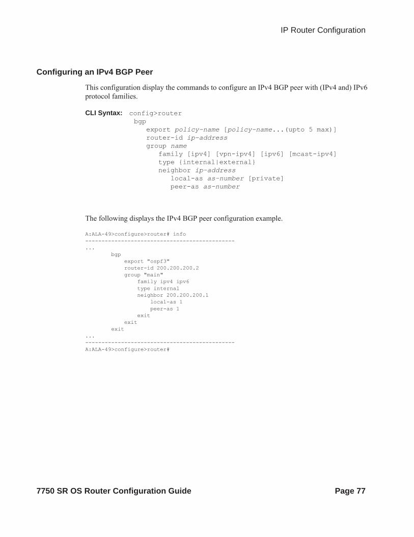
IP Router Configuration
Configuring an IPv4 BGP Peer
This configuration display the commands to configure an IPv4 BGP peer with (IPv4 and) IPv6 protocol families.
CLI Syntax: config>routerbgp
export policy-name [policy-name...(upto 5 max)]router-id ip-addressgroup name
family [ipv4] [vpn-ipv4] [ipv6] [mcast-ipv4]type {internal|external}neighbor ip-address
local-as as-number [private]peer-as as-number
The following displays the IPv4 BGP peer configuration example.
A:ALA-49>configure>router# info----------------------------------------------... bgp export "ospf3" router-id 200.200.200.2 group "main" family ipv4 ipv6 type internal neighbor 200.200.200.1 local-as 1 peer-as 1 exit exit exit...----------------------------------------------A:ALA-49>configure>router#
7750 SR OS Router Configuration Guide Page 77

Common Configuration Tasks
An Example of a IPv6 Over IPv4 Tunnel Configuration
The IPv6 address is the next-hop as it is received through BGP. The IPv4 address is the system address of the tunnel's endpoint static-route ::C8C8:C802/128 indirect 200.200.200.2
This configuration displays an example to configure a policy to export IPv6 routes into BGP.
CLI Syntax: config>routerbgp
export policy-name [policy-name...(upto 5 max)]router-id ip-addressgroup name
family [ipv4] [vpn-ipv4] [ipv6] [mcast-ipv4]type {internal|external}neighbor ip-address
local-as as-number [private]peer-as as-number
The following displays an IPv6 over IPv4 tunnel configuration
A:ALA-49>configure>router# info----------------------------------------------... policy-options policy-statement "ospf3" description "Plcy Stmnt For 'From ospf3 To bgp'" entry 10 description "Entry From Protocol ospf3 To bgp" from protocol ospf3 exit to protocol bgp exit action accept exit exit exit exit----------------------------------------------A:ALA-49>configure>router#
Page 78 7750 SR OS Router Configuration Guide

IP Router Configuration
Router Advertisement
To configure the router to originate router advertisement messages on an interface, the interface must be configured under the router-advertisement context and be enabled (no shutdown). All other router advertisement configuration parameters are optional.
Use the following CLI syntax to enable router advertisement and configure router advertisement parameters:
CLI Syntax: config>router# router-advertisementinterface ip-int-name
current-hop-limit numbermanaged-configurationmax-advertisement-interval secondsmin-advertisement-interval secondsmtu mtu-bytesother-stateful-configurationprefix ipv6-prefix/prefix-length
autonomouson-linkpreferred-lifetime {seconds | infinite}valid-lifetime {seconds | infinite}
reachable-time milli-secondsretransmit-time milli-secondsrouter-lifetime secondsno shutdownuse-virtual-mac
The following displays a router advertisement configuration example.
*A:sim131>config>router>router-advert# info ---------------------------------------------- interface "n1" prefix 3::/64 exit use-virtual-mac no shutdown exit----------------------------------------------*A:sim131>config>router>router-advert# interface n1 *A:sim131>config>router>router-advert>if# prefix 3::/64 *A:sim131>config>router>router-advert>if>prefix# info detail ---------------------------------------------- autonomous on-link preferred-lifetime 604800 valid-lifetime 2592000----------------------------------------------*A:tahi>config>router>router-advert>if>prefix#
7750 SR OS Router Configuration Guide Page 79

Common Configuration Tasks
Configuring IPv6 Parameters
The following displays the interface configuration showing the IPv6 default configuration when IPv6 is enabled on the interface.
A:ALA-49>config>router>if>ipv6# info detail---------------------------------------------- port 1/3/37 ipv6 packet-too-big 100 10 param-problem 100 10 redirects 100 10 time-exceeded 100 10 unreachables 100 10 exit----------------------------------------------A:ALA-49>config>router>if>ipv6# exit all
The following displays an IPv6 configuration example.
A:ALA-49>config>router>if# info---------------------------------------------- address 10.11.10.1/24 port 1/3/37 ipv6 address 10::1/24 exit----------------------------------------------A:ALA-49>config>router>if#
An Example of a IPv6 Over IPv4 Tunnel Configuration
The IPv6 address is the next-hop as it is received through BGP. The IPv4 address is the system address of the tunnel's endpoint static-route ::C8C8:C802/128 indirect 200.200.200.2
This configuration displays an example to configure a policy to export IPv6 routes into BGP.
CLI Syntax: config>routerbgp
export policy-name [policy-name...(upto 5 max)]router-id ip-addressgroup name
family [ipv4] [vpn-ipv4] [ipv6] [mcast-ipv4]type {internal|external}neighbor ip-address
local-as as-number [private]peer-as as-number
The following displays the configuration showing the policy output.
Page 80 7750 SR OS Router Configuration Guide

IP Router Configuration
A:ALA-49>configure>router# info----------------------------------------------... policy-options policy-statement "ospf3" description "Plcy Stmnt For 'From ospf3 To bgp'" entry 10 description "Entry From Protocol ospf3 To bgp" from protocol ospf3 exit to protocol bgp exit action accept exit exit exit exit----------------------------------------------A:ALA-49>configure>router#
7750 SR OS Router Configuration Guide Page 81
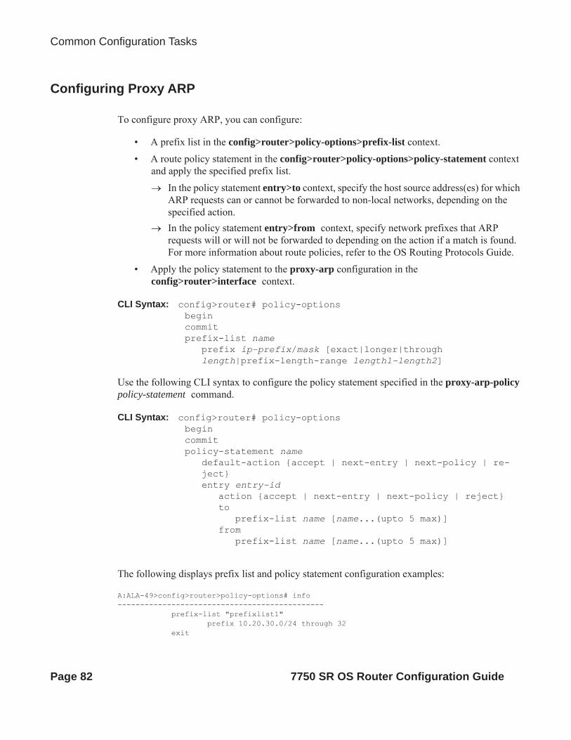
Common Configuration Tasks
Configuring Proxy ARP
To configure proxy ARP, you can configure:
• A prefix list in the config>router>policy-options>prefix-list context.• A route policy statement in the config>router>policy-options>policy-statement context
and apply the specified prefix list. In the policy statement entry>to context, specify the host source address(es) for which
ARP requests can or cannot be forwarded to non-local networks, depending on the specified action.
In the policy statement entry>from context, specify network prefixes that ARP requests will or will not be forwarded to depending on the action if a match is found. For more information about route policies, refer to the OS Routing Protocols Guide.
• Apply the policy statement to the proxy-arp configuration in the config>router>interface context.
CLI Syntax: config>router# policy-optionsbegincommitprefix-list name
prefix ip-prefix/mask [exact|longer|through length|prefix-length-range length1-length2]
Use the following CLI syntax to configure the policy statement specified in the proxy-arp-policy policy-statement command.
CLI Syntax: config>router# policy-optionsbegincommitpolicy-statement name
default-action {accept | next-entry | next-policy | re-ject}entry entry-id
action {accept | next-entry | next-policy | reject}to
prefix-list name [name...(upto 5 max)]from
prefix-list name [name...(upto 5 max)]
The following displays prefix list and policy statement configuration examples:
A:ALA-49>config>router>policy-options# info---------------------------------------------- prefix-list "prefixlist1" prefix 10.20.30.0/24 through 32 exit
Page 82 7750 SR OS Router Configuration Guide

IP Router Configuration
prefix-list "prefixlist2" prefix 10.10.10.0/24 through 32 exit... policy-statement "ProxyARPpolicy" entry 10 from prefix-list "prefixlist1" exit to prefix-list "prefixlist2" exit action reject exit default-action accept exit exit...----------------------------------------------A:ALA-49>config>router>policy-options#
Use the following CLI to configure proxy ARP:
CLI Syntax: config>router>interface interface-namelocal-proxy-arpproxy-arp-policy policy-name [policy-name...(upto 5 max)]remote-proxy-arp
The following displays a proxy ARP configuration example:
A:ALA-49>config>router>if# info---------------------------------------------- address 128.251.10.59/24 local-proxy-arp proxy-arp policy-statement "ProxyARPpolicy" exit----------------------------------------------A:ALA-49>config>router>if#
7750 SR OS Router Configuration Guide Page 83

Common Configuration Tasks
Creating an IP Address Range
An IP address range can be reserved for exclusive use for services by defining the config>router>service-prefix command. When the service is configured, the IP address must be in the range specified as a service prefix. If no service prefix command is configured, then no limitation exists.
The no service-prefix ip-prefix/mask command removes all address reservations. A service prefix cannot be removed while one or more services use address(es) in the range to be removed.
CLI Syntax: config>routerservice-prefix ip-prefix/mask [exclusive]
Configuring an LDP Shortcut
This command enables you to forward user IP packets and specified control IP packets using LDP shortcuts over all network interfaces in the system that participate in the IS-IS and OSPF routing protocols. The default is to disable the LDP shortcut across all interfaces in the system.
IGP Route Resolution
When LDP shortcut is enabled, LDP populates the RTM with next-hop entries corresponding to all prefixes for which it activated an LDP FEC. For a given prefix, two route entries are populated in RTM. One corresponds to the LDP shortcut next-hop and has an owner of LDP. The other one is the regular IP next-hop. The LDP shortcut next-hop always has preference over the regular IP next-hop for forwarding user packets and specified control packets over a given outgoing interface to the route next-hop.
The prior activation of the FEC by LDP is done by performing an exact match with an IGP route prefix in RTM. It can also be done by performing a longest prefix-match with an IGP route in RTM if the aggregate-prefix-match option is enabled globally in LDP ldp-interarea-prd.
Note that the LDP next-hop entry is not exported to LDP control plane or to any other control plane protocols except OSPF, IS-IS, and specific OAM control plane as specified in Handling of Control Packets on page 86.
This feature is not restricted to /32 FEC prefixes. However only /32 FEC prefixes will be populated in the Tunnel Table for use as a tunnel by services.
All user and specified control packets for which the longest prefix match in RTM yields the FEC prefix will be forwarded over the LDP LSP. The following is an example of the resolution process.
Page 84 7750 SR OS Router Configuration Guide

IP Router Configuration
Assume the egress LER advertised a FEC for some /24 prefix using the fec-originate command. At the ingress LER, LDP resolves the FEC by checking in RTM that an exact match exists for this prefix. Once LDP activated the FEC, it programs the NHLFE in the egress data path and the LDP tunnel information in the ingress data path tunnel table.
Next, LDP provides the shortcut route to RTM which will associate it with the same /24 prefix. There will be two entries for this /24 prefix, the LDP shortcut next-hop and the regular IP next-hop. The latter was used by LDP to validate and activate the FEC. RTM then resolves all user prefixes which succeed a longest prefix match against the /24 route entry to use the LDP LSP.
Assume now the aggregate-prefix-match was enabled and that LDP found a /16 prefix in RTM to activate the FEC for the /24 FEC prefix. In this case, RTM adds a new more specific route entry of /24 and has the next-hop as the LDP LSP but it will still not have a specific /24 IP route entry. RTM then resolves all user prefixes which succeed a longest prefix match against the /24 route entry to use the LDP LSP while all other prefixes which succeed a longest prefix-match against the /16 route entry will use the IP next-hop. LDP shortcut will also work when using RIP for routing.
LDP Shortcut Forwarding Plane
Once LDP activated a FEC for a given prefix and programmed RTM, it also programs the ingress Tunnel Table in IOM with the LDP tunnel information.
When an IPv4 packet is received on an ingress network interface, a subscriber IES interface, or a regular IES interface, the lookup of the packet by the ingress IOM will result in the packet being sent labeled with the label stack corresponding to the NHLFE of the LDP LSP when the preferred RTM entry corresponds to an LDP shortcut.
If the preferred RTM entry corresponds to an IP next-hop, the IPv4 packet is forwarded unlabelled.
The switching from the LDP shortcut next-hop to the regular IP next-hop when the LDP FEC becomes unavailable depends on whether the next-hop is still available. If it is (for example, the LDP FEC was withdrawn due to LDP control plane issues) the switchover should be faster. If the next-hop determination requires IGP to re-converge, this will take longer. However no target is set.
The switching from a regular IP next-hop to an LDP shortcut next-hop will normally occur only when both are available. However, the programming of the NHLFE by LDP and the programming of the LDP tunnel information in the ingress IOM tunnel table are asynchronous. If Tunnel Table is configured first, it is possible that traffic will be black holed for some time .
ECMP Considerations
When ECMP is enabled and multiple equal-cost next-hops exit for the IGP route, the ingress IOM will spray the packets for this route based on hashing routine currently supported for IPv4 packets.
7750 SR OS Router Configuration Guide Page 85

Common Configuration Tasks
When the preferred RTM entry corresponds to an LDP shortcut route, spraying will be performed across the multiple next-hops for the LDP FEC. The FEC next-hops can either be direct link LDP neighbors or T-LDP neighbors reachable over RSVP LSPs in the case of LDP-over-RSVP but not both. This is as per ECMP for LDP in existing implementation.
When the preferred RTM entry corresponds to a regular IP route, spraying will be performed across regular IP next-hops for the prefix.
Spraying across regular IP next-hops and LDP-shortcut next-hops concurrently is not supported.
Handling of Control Packets
All control plane packets will not see the LDP shortcut route entry in RTM with the exception of the following control packets which will be forwarded over an LDP shortcut when enabled:
• A locally generated or in transit ICMP Ping and trace route of an IGP route. The transit message appears as a user packet to the ingress LER node.
• A locally generated response to a received ICMP ping or trace route message.
All other control plane packets that require an RTM lookup and knowledge of which destination is reachable over the LDP shortcut will continue to be forwarded over the IP next-hop route in RTM.
Handling of Multicast Packets
Multicast packets cannot be forwarded or received from an LDP LSP. This is because there is no support for the configuration of such an LSP as a tunnel interfaces in PIM. Only an RSVP P2MP LSP is currently allowed.
If a multicast packet is received over the physical interface, the RPF check will not resolve to the LDP shortcut as the LDP shortcut route in RTM is not made available to multicast application.
Interaction with LDP Shortcut for BGP Route Resolution
There is no interaction between an LDP shortcut for BGP next-hop resolution and the LDP shortcut for IGP route resolution. BGP will continue to resolve a BGP next-hop to an LDP shortcut if the user enabled the LDP shortcut option in BGP BGP-Shortcut:
CLI Syntax: config>router>bgp>igp-shortcut ldp
Page 86 7750 SR OS Router Configuration Guide

IP Router Configuration
Interaction with LDP Shortcut for Static Route Resolution
There is no interaction between LDP shortcut for static route resolution and the LDP shortcut for IGP route resolution. A static route will continue to be resolved by searching an LDP LSP which FEC prefix matches the specified indirect next-hop for the route. In contrast, the LDP shortcut for IGP route resolution uses the LDP LSP as a route.
LDP Control Plane
In order for the LDP shortcut to be usable, an SR-OS router must originate a <FEC, label> binding for each IGP route it learns of even if it did not receive a binding from the next-hop for that route. In other words, it must assume it is an egress LER for the FEC until the route disappears from the routing table or the next-hop advertised a binding for the FEC prefix. In the latter case, the SR-OS router becomes a transit LSR for the FEC.
An SR-OS router will originate a <FEC, label> binding for its system interface address only by default. The only way to originate a binding for local interfaces and routes which are not local to the system is by using the fec-originate capability.
You must use the fec-originate command to generate bindings for all non-local routes for which this node acts as an egress LER for the corresponding LDP FEC. Specifically, this feature must support the FEC origination of IGP learned routes and subscriber/host routes statically configured or dynamically learned over subscriber IES interfaces.
An LDP LSP used as a shortcut by IPv4 packets may also be tunneled using the LDP-over-RSVP feature.
7750 SR OS Router Configuration Guide Page 87
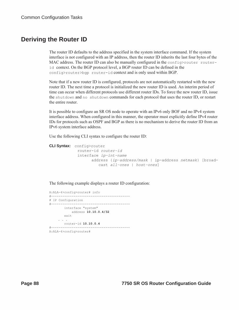
Common Configuration Tasks
Deriving the Router ID
The router ID defaults to the address specified in the system interface command. If the system interface is not configured with an IP address, then the router ID inherits the last four bytes of the MAC address. The router ID can also be manually configured in the config>router router-id context. On the BGP protocol level, a BGP router ID can be defined in the config>router>bgp router-id context and is only used within BGP.
Note that if a new router ID is configured, protocols are not automatically restarted with the new router ID. The next time a protocol is initialized the new router ID is used. An interim period of time can occur when different protocols use different router IDs. To force the new router ID, issue the shutdown and no shutdown commands for each protocol that uses the router ID, or restart the entire router.
It is possible to configure an SR OS node to operate with an IPv6 only BOF and no IPv4 system interface address. When configured in this manner, the operator must explicitly define IPv4 router IDs for protocols such as OSPF and BGP as there is no mechanism to derive the router ID from an IPv6 system interface address.
Use the following CLI syntax to configure the router ID:
CLI Syntax: config>router router-id router-idinterface ip-int-name
address {ip-address/mask | ip-address netmask} [broad-cast all-ones | host-ones]
The following example displays a router ID configuration:
A:ALA-4>config>router# info#------------------------------------------# IP Configuration#------------------------------------------ interface "system" address 10.10.0.4/32 exit
. . . router-id 10.10.0.4#------------------------------------------A:ALA-4>config>router#
Page 88 7750 SR OS Router Configuration Guide

IP Router Configuration
Configuring a Confederation
Configuring a confederation is optional. The AS and confederation topology design should be carefully planned. Autonomous system (AS), confederation, and BGP connection and peering parameters must be explicitly created on each participating router. Identify AS numbers, confederation numbers, and members participating in the confederation.
Refer to the BGP section for CLI syntax and command descriptions.
Use the following CLI syntax to configure a confederation:
CLI Syntax: config>routerconfederation confed-as-num members member-as-num
The following example displays the commands to configure the confederation topology diagram displayed in Figure 2 on page 39.
NOTES:
• Confederations can be preconfigured prior to configuring BGP connections and peering. • Each confederation can have up to 15 members.
The following displays a confederation example.
A:ALA-B>config>router# info#------------------------------------------# IP Configuration#------------------------------------------ interface "system" address 10.10.10.103/32 exit interface "to-104" shutdown address 10.0.0.103/24 port 1/1/1 exit autonomous-system 100 confederation 2002 members 200 300 400 router-id 10.10.10.103
#------------------------------------------A:ALA-B>config>router#
7750 SR OS Router Configuration Guide Page 89

Common Configuration Tasks
Configuring an Autonomous System
Configuring an autonomous system is optional. Use the following CLI syntax to configure an autonomous system:
CLI Syntax: config>routerautonomous-system as-number
The following displays an autonomous system configuration example:
A;ALA-A>config>router# info#------------------------------------------# IP Configuration#------------------------------------------ interface "system" address 10.10.10.103/32 exit interface "to-104" address 10.0.0.103/24 port 1/1/1 exit exit autonomous-system 100 router-id 10.10.10.103#------------------------------------------A:ALA-A>config>router#
Page 90 7750 SR OS Router Configuration Guide

IP Router Configuration
Configuring Overload State on a Single SFM
A 7x50 system with a single SFM installed has a system multicast throughput that is only a half of a 7x50 system with dual SFMs installed. For example, in a mixed environment in which IOM1s, IOM2s, and IOM3s are installed in the same system (chassis mode B or C), system multicast throughput doubles when redundant SFMs are used instead of a single SFM. If the required system multicast throughput is between 16G and 32G (which means both SFMs are being actively used), when there is an SFM failure, multicast traffic needs to be rerouted around the node.
Some scenarios include:
• There is only one SFM installed in the system• One SFM (active or standby) failed in a dual SFM configuration • The system is in the ISSU process
You can use an overload state in IGP to trigger the traffic reroute by setting the overload bit in IS-IS or setting the metric to maximum in OSPF. Since PIM uses IGP to find out the upstream router, a next-hop change in IGP will cause PIM to join the new path and prune the old path, which effectively reroutes the multicast traffic downstream. When the problem is resolved, the overload condition is cleared, which will cause the traffic to be routed back to the router.
7750 SR OS Router Configuration Guide Page 91

Service Management Tasks
Service Management TasksThis section discusses the following service management tasks:
• Changing the System Name on page 92• Modifying Interface Parameters on page 93• Deleting a Logical IP Interface on page 94
Changing the System Name
The system command sets the name of the device and is used in the prompt string. Only one system name can be configured. If multiple system names are configured, the last one configured will overwrite the previous entry.
Use the following CLI syntax to change the system name:
CLI Syntax: config# systemname system-name
The following example displays the command usage to change the system name:
Example: A:ALA-A>config>system# name tgifA:TGIF>config>system#
The following example displays the system name change:
A:ALA-A>config>system# name TGIFA:TGIF>config>system# info#------------------------------------------# System Configuration#------------------------------------------ name "TGIF"
location "Mt.View, CA, NE corner of FERG 1 Building"coordinates "37.390, -122.05500 degrees lat."synchronizesnmp
exit security snmp community "private" rwa version both exit exit . . .----------------------------------------------A:TGIF>config>system#
Page 92 7750 SR OS Router Configuration Guide

IP Router Configuration
Modifying Interface Parameters
Starting at the config>router level, navigate down to the router interface context.
To modify an IP address, perform the following steps:
Example:A:ALA-A>config>router# interface “to-sr1”A:ALA-A>config>router>if# shutdownA:ALA-A>config>router>if# no addressA:ALA-A>config>router>if# address 10.0.0.25/24A:ALA-A>config>router>if# no shutdown
To modify a port, perform the following steps:
Example:A:ALA-A>config>router# interface “to-sr1”A:ALA-A>config>router>if# shutdownA:ALA-A>config>router>if# no port A:ALA-A>config>router>if# port 1/1/2A:ALA-A>config>router>if# no shutdown
The following example displays the interface configuration:
A:ALA-A>config>router# info#------------------------------------------# IP Configuration#------------------------------------------ interface "system" address 10.0.0.103/32 exit interface "to-sr1" address 10.0.0.25/24 port 1/1/2 exit router-id 10.10.0.3#------------------------------------------A:ALA-A>config>router#
7750 SR OS Router Configuration Guide Page 93
Service Management Tasks
Deleting a Logical IP Interface
The no form of the interface command typically removes the entry, but all entity associations must be shut down and/or deleted before an interface can be deleted.
1. Before an IP interface can be deleted, it must first be administratively disabled with the shutdown command.
2. After the interface has been shut down, it can then be deleted with the no interface command.
CLI Syntax: config>routerno interface ip-int-name
Example: config>router# interface test-interfaceconfig>router>if# shutdownconfig>router>if# exitconfig>router# no interface test-interfaceconfig>router#
Page 94 7750 SR OS Router Configuration Guide
IP Router Configuration
IP Router Command Reference
Command Hierarchies
Configuration Commands• Router Commands on page 96
• Router L2TP Commands on page 99
• Router Interface Commands on page 102
• Router Interface IPv6 Commands on page 105
• Router Advertisement Commands on page 106
• Show Commands on page 107
• Clear Commands on page 109
• Debug Commands on page 110
7750 SR OS Router Configuration Guide Page 95

IP Router Command Reference
Router Commandsconfig
— router [router-name]— aggregate ip-prefix/ip-prefix-length [summary-only] [as-set] [aggregator as-number:ip-
address] [black-hole] [community comm-id] [description description]— aggregate ip-prefix/ip-prefix-length [summary-only] [as-set] [aggregator as-number:ip-
address] [community comm-id] [indirect ip-address] [description description]— no aggregate ip-prefix/ip-prefix-length— autonomous-system autonomous-system— no autonomous-system— confederation confed-as-num members as-number [as-number...(up to 15 max)]— no confederation [confed-as-num members as-number....(up to 15 max)]— ecmp max-ecmp-routes— no ecmp— fib-priority {high | standard}— [no] icmp-tunneling— [no] ignore-icmp-redirect— [no] ip-fast-reroute— [no] ldp-shortcut— mc-maximum-routes number [log-only] [threshold threshold]— no mc-maximum-routes— mpls-labels
— static-label max-lsp-labels number static-svc-labels number— no static-label
— multicast-info policy-name— no multicast-info— multicast-info
— description description-string— no description
— origin-validation— [no] rpki-session ip-address
— [no] connect-retryseconds— [no] description string— [no] local-address ip-address— [no] port number— [no] refresh-time seconds hold-time seconds— [no] shutdown— [no] stale-time seconds— static-entry ip-prefix/prefix-length1-prefix-length2 origin-as as-number
[valid | invalid]— no static-entry ip-prefix/prefix-length1-prefix-length2
— router-id ip-address— no router-id — service-prefix {ip-prefix/mask | ip-prefix netmask}[exclusive]— no service-prefix ip-prefix/mask | ip-prefix netmask}— sgt-qos
— application dscp-app-name dscp {dscp-value | dscp-name}— application dot1p-app-name dot1p dot1p-priority— no application {dscp-app-name | dot1p-app-name}— dscp dscp-name fc fc-name— [no] dscp dscp-name
— single-sfm-overload [holdoff-time holdoff-time]— no single-sfm-overload
Page 96 7750 SR OS Router Configuration Guide

IP Router Configuration
— [no] static-route {ip-prefix/prefix-length| ip-prefix netmask} [preference preference] [met-ric metric] [tag tag] [enable|disable] next-hop ip-int-name|ip-address [validate-next-hop] [mcast-family] [community comm-id][bfd-enable|{cpe-check cpe-ip-address [interval sec-onds] [drop-count count] [padding-size padding-size] [log]}| {prefix-list prefix-list-name [all|none]}][fc fc-name [priority {low|high}]] [source-class source-index][dest-class dest-index][ldp-sync][description description]
— [no] static-route {ip-prefix/prefix-length | ip-prefix netmask} [preference preference] [met-ric metric] [tag tag] [community comm-id] [enable | disable] indirect ip-address [ldp | rsvp-te [disallow-igp]] [cpe-check cpe-ip-address [interval seconds] [drop-count count] [log]]
— [no] static-route {ip-prefix/prefix-length | ip-prefix netmask} [preference preference] [met-ric metric] [tag tag] [community comm-id] [enable | disable] black-hole [mcast-family]
— [no] triggered-policy— ttl-propagate
— label-route-local [none | all] — label-route-transit [none | all]— lsr-label-route [none | all]— vprn-local [none | vc-only | all]— vprn-transit [none | vc-only | all]
config— router management
— origin-validation— [no] rpki-session ip-address
— [no] connect-retryseconds— [no] description string— [no] local-address ip-address— [no] port number— [no] refresh-time seconds hold-time seconds— [no] shutdown— [no] stale-time seconds
7750 SR OS Router Configuration Guide Page 97

IP Router Command Reference
Router BFD commandsconfig
— router— bfd— bfd-template name [create]— bfd-template name
— transmit-interval transmit-interval— no transmit-interval— receive-interval receive-interval— no receive-interval— cv-tx transmit-interval— no cv-tx— echo-receive echo-interval— no echo-receive— multiplier multiplier— no multiplier— [no] type cpm-np
Page 98 7750 SR OS Router Configuration Guide

IP Router Configuration
Router L2TP Commandsconfig
— router [router-name]— l2tp
— calling-number-format ascii-spec— no calling-number-format— challenge {always}— no challenge— df-bit-lac {always|never}— no df-bit-lac— destruct-timeout destruct-timeout— no destruct-timeout— exclude-avps calling-number— no exclude-avps— group tunnel-group-name [create] — no group tunnel-group-name
— avp-hiding sensitive | always— no avp-hiding— challenge always— no challenge— description description-string— no description— df-bit-lac {always|never|default}— no df-bit-lac— destruct-timeout destruct-timeout— no destruct-timeout— hello-interval hello-interval— no hello-interval— idle-timeout idle-timeout— no idle-timeout— lns-group lns-group-id— no lns-group— load-balance-method {per-session|per-tunnel}— no load-balance-method— local-address ip-address— no local-address— local-name host-name— no local-name— max-retries-estab max-retries— no max-retries-estab— max-retries-not-estab max-retries— no max-retries-not-estab— password password [hash | hash2]— no password— ppp
— authentication {chap|pap|pref-chap}— authentication-policy auth-policy-name— no authentication-policy— default-group-interface ip-int-name service-id service-id— no default-group-interface— keepalive seconds [hold-up-multiplier multiplier]— no keepalive— mtu mtu-bytes— no mtu
7750 SR OS Router Configuration Guide Page 99
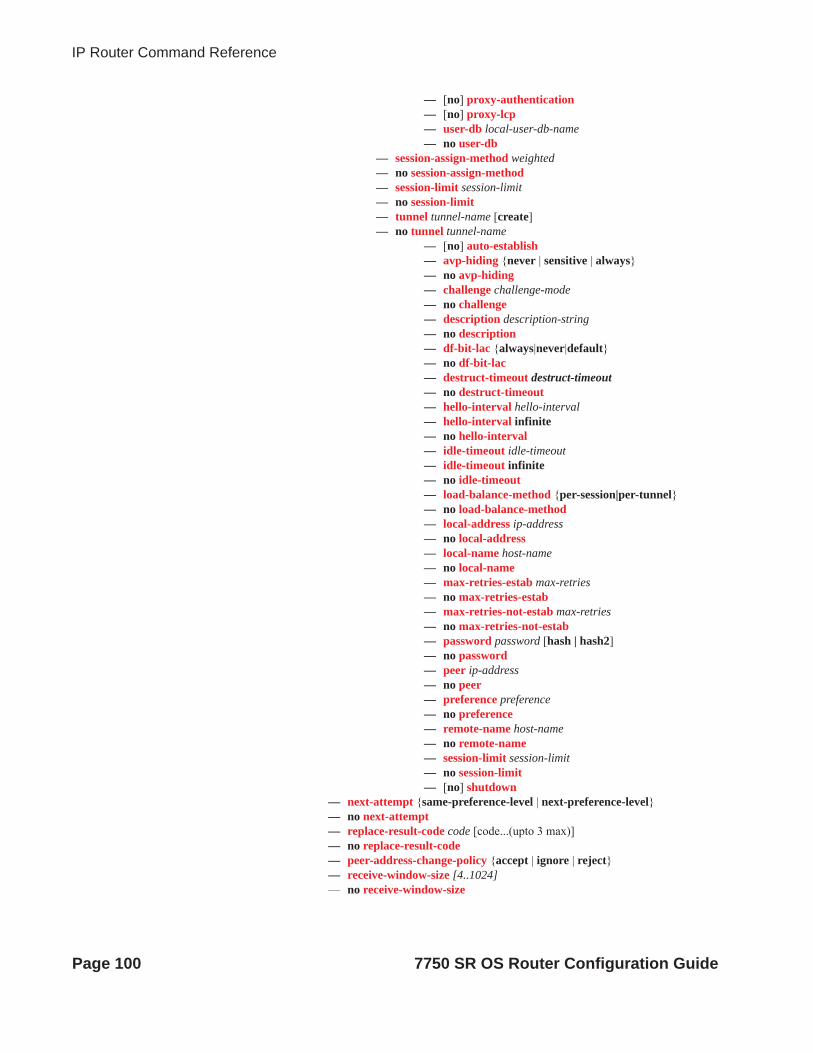
IP Router Command Reference
— [no] proxy-authentication— [no] proxy-lcp— user-db local-user-db-name— no user-db
— session-assign-method weighted— no session-assign-method— session-limit session-limit— no session-limit— tunnel tunnel-name [create]— no tunnel tunnel-name
— [no] auto-establish— avp-hiding {never | sensitive | always}— no avp-hiding— challenge challenge-mode— no challenge— description description-string— no description— df-bit-lac {always|never|default}— no df-bit-lac— destruct-timeout destruct-timeout— no destruct-timeout— hello-interval hello-interval— hello-interval infinite— no hello-interval— idle-timeout idle-timeout— idle-timeout infinite— no idle-timeout— load-balance-method {per-session|per-tunnel}— no load-balance-method— local-address ip-address— no local-address— local-name host-name— no local-name— max-retries-estab max-retries— no max-retries-estab— max-retries-not-estab max-retries— no max-retries-not-estab— password password [hash | hash2]— no password— peer ip-address— no peer— preference preference— no preference— remote-name host-name— no remote-name— session-limit session-limit— no session-limit— [no] shutdown
— next-attempt {same-preference-level | next-preference-level} — no next-attempt— replace-result-code code [code...(upto 3 max)]— no replace-result-code— peer-address-change-policy {accept | ignore | reject}— receive-window-size [4..1024]— no receive-window-size
Page 100 7750 SR OS Router Configuration Guide

IP Router Configuration
— [no] shutdownconfigure
— router— l2tp
— tunnel-selection-blacklist— add-tunnel never— add-tunnel on reason>[reason...(upto 8 max)]— no add-tunnel— add-tunnel— max-list-length count— no max-list-length— max-time minutes— no max-time— timeout-action action— no timeout-action
7750 SR OS Router Configuration Guide Page 101
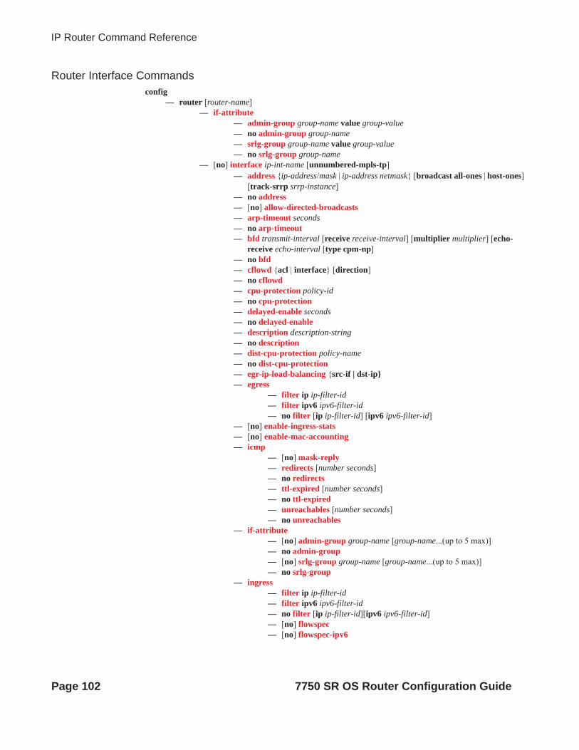
IP Router Command Reference
Router Interface Commandsconfig
— router [router-name]— if-attribute
— admin-group group-name value group-value— no admin-group group-name— srlg-group group-name value group-value— no srlg-group group-name
— [no] interface ip-int-name [unnumbered-mpls-tp]— address {ip-address/mask | ip-address netmask} [broadcast all-ones | host-ones]
[track-srrp srrp-instance]— no address— [no] allow-directed-broadcasts— arp-timeout seconds — no arp-timeout— bfd transmit-interval [receive receive-interval] [multiplier multiplier] [echo-
receive echo-interval [type cpm-np]— no bfd— cflowd {acl | interface} [direction]— no cflowd— cpu-protection policy-id— no cpu-protection— delayed-enable seconds— no delayed-enable— description description-string— no description— dist-cpu-protection policy-name— no dist-cpu-protection— egr-ip-load-balancing {src-if | dst-ip}— egress
— filter ip ip-filter-id— filter ipv6 ipv6-filter-id— no filter [ip ip-filter-id] [ipv6 ipv6-filter-id]
— [no] enable-ingress-stats— [no] enable-mac-accounting— icmp
— [no] mask-reply— redirects [number seconds]— no redirects— ttl-expired [number seconds]— no ttl-expired— unreachables [number seconds]— no unreachables
— if-attribute— [no] admin-group group-name [group-name...(up to 5 max)]— no admin-group — [no] srlg-group group-name [group-name...(up to 5 max)]— no srlg-group
— ingress— filter ip ip-filter-id — filter ipv6 ipv6-filter-id— no filter [ip ip-filter-id][ipv6 ipv6-filter-id] — [no] flowspec— [no] flowspec-ipv6
Page 102 7750 SR OS Router Configuration Guide

IP Router Configuration
— ip-load-balancing {source|destination}— no ip-load-balancing— lag-link-map-profile lnk-map-profile-id— no lag-link-map-profile— ldp-sync-timer seconds— no ldp-sync-timer— [no] local-proxy-arp— [no] loopback— lsr-load-balancing hashing-algorithm— no lsr-load-balancing— mac ieee-mac-addr— no mac — [no] multihoming primary|secondary [hold-time holdover-time]— network-domain network-domain-name— no network-domain— [no] ntp-broadcast— port port-name— no port— [no] proxy-arp-policy— [no] ptp-hw-assist— qos-route-lookup [source | destination]— no qos-route-lookup— qos network-policy-id [egress-port-redirect-group queue-group-name] [egress-
instance instance-id]] [ingress-fp- redirect-group queue-group-name ingress-instance instance-id]
— no qos— [no] remote-proxy-arp— secondary {[ip-addr/mask | ip-addr][netmask]} [broadcast {all-ones | host-
ones}] [igp-inhibit]— no secondary [ip-addr/mask | ip-addr][netmask ]— [no] shutdown— static-arp ip-addr ieee-mac-addr unnumbered— no static-arp unnumbered— [no] strip-label — tcp-mss mss-value— no tcp-mss— [no] teid-load-balancing— tos-marking-state {trusted | untrusted}— no tos-marking-state— unnumbered [ip-addr | ip-int-name]— no unnumbered— [no] urpf-check
— mode {strict|loose|strict-no-ecmp}— no mode
— [no] mh-primary-interface— address {ip-address/mask | ip-address netmask}— no address— description description-string— no description— [no] shutdown
— [no] mh-secondary-interface— hold-time holdover-time— no hold-time— address {ip-address/mask | ip-address netmask}— no address
7750 SR OS Router Configuration Guide Page 103

IP Router Command Reference
— description description-string— no description— [no] shutdown
— route-next-hop-policy— [no] template template-name
— include-group group-name [pref pref]— no include-group group-name— [no] exclude-group group-name— [no] srlg-enable— protection-type {link | node}— no protection-type— nh-type {ip | tunnel}— no nh-type
For router interface VRRP commands, see VRRP Command Reference on page 355.
Page 104 7750 SR OS Router Configuration Guide

IP Router Configuration
Router Interface IPv6 Commandsconfig
— router [router-name]— [no] interface ip-int-name
— [no] ipv6— address ipv6-address/prefix-length [eui-64]— no address ipv6-address/prefix-length — bfd transmit-interval [receive receive-interval] [multiplier multiplier]
[echo-receive echo-interval [type cpm-np]— no bfd— [no] dad-disable— icmp6
— packet-too-big [number seconds]— no packet-too-big— param-problem [number seconds]— no param-problem— redirects [number seconds] — no redirects— time-exceeded [number seconds]— no time-exceeded— unreachables [number seconds] — no unreachables
— [no] local-proxy-nd— neighbor ipv6-address [mac-address]— no neighbor ipv6-address— proxy-nd-policy policy-name [ policy-name...(up to 5 max)]— no proxy-nd-policy— [no] qos-route-lookup— tcp-mss mss-value— no tcp-mss— [no] urpf-check
— mode {strict | loose | strict-no-ecmp} — no mode
— [no] qos-route-lookup— [no] urpf-check
— mode {strict | loose} — no mode
7750 SR OS Router Configuration Guide Page 105

IP Router Command Reference
Router Advertisement Commandsconfig
— router— [no] router-advertisement
— [no] interface ip-int-name— current-hop-limit number— no current-hop-limit— [no] managed-configuration — max-advertisement-interval seconds— no max-advertisement-interval— min-advertisement-interval seconds— no min-advertisement-interval— mtu mtu-bytes— no mtu— [no] other-stateful-configuration— prefix [ipv6-prefix/prefix-length]
— [no] autonomous— [no] on-link— preferred-lifetime {seconds | infinite}— no preferred-lifetime— valid-lifetime {seconds | infinite}— no valid-lifetime
— reachable-time milli-seconds— no reachable-time— retransmit-time milli-seconds— no retransmit-time— router-lifetime seconds— no router-lifetime— [no] shutdown— [no] use-virtual-mac
Page 106 7750 SR OS Router Configuration Guide

IP Router Configuration
Show Commandsshow
— router router-instance— router service-name service-name
— aggregate [family] [active]— arp [ ip-int-name | ip-address/mask | mac ieee-mac-address | summary] [local | dynamic |
static | managed]— authentication
— statistics— statistics interface [ip-int-name | ip-address]— statistics policy name
— bfd— bfd-template template-name— interface [interface-name]— session [src ip-address [dst ip-address] | [detail]]— session [type type]— session [summary]
— dhcp— statistics [ip-int-name | ip-address]— summary
— dhcp6— statistics [ip-int-name | ip-address]— summary
— ecmp— fib slot-number [family] [ip-prefix/prefix-length [longer]] [secondary]— fib slot-number [family] summary— fib slot-number nh-table-usage— fp-tunnel-table slot-number [ip-prefix/prefix-length]— icmp6— interface [{[ip-address|ip-int-name][detail] [family]}|summary| exclude-services]— interface ip-address|ip-int-name eth-cfm [detail]— interface ip-address|ip-int-name mac [ieee-address]— interface ip-address|ip-int-name statistics— interface dist-cpu-protection [detail]— interface policy-accounting [class [index]]— l2tp
— group [tunnel-group-name [statistics]]— group connection-id connection-id [detail]| — group [detail] [session-id session-id (v2)] [state session-state][peer ip-address]
[group group-name] [assignment-id assignment-id] [local-namelocal-host-name] [remote-name remote-host-name] [tunnel-id tunnel-id (v2)]|
— session [detail] [state session-state] [peer ip-address] [group group-name] [assignment-id assignment-id] [local-name local-host-name] [remote-name remote-host-name] [control-connection-id connection-id (v3)]
— statistics— tunnel [statistics] [detail] [peer ip-address] [state tunnel-state] [remote-connec-
tion-id remote-connection-id (v3)] [group group-name] [assignment-id assign-ment-id] [local-name host-name] [remote-name host-name]| tunnel [statistics] [detail] [peer ip-address] [state tunnel-state] [remote-tunnel-id remote-tunnel-id (v2)] [group group-name] [assignment-id assignment-id] [local-name host-name] [remote-name host-name]
— tunnel tunnel-id tunnel-id (v2) [statistics] [detail]— tunnel connection-id connection-id (v3) [statistics] [detail]
— ldp
7750 SR OS Router Configuration Guide Page 107

IP Router Command Reference
— bindings active— mvpn— neighbor [ip-address | ip-int-name | mac ieee-mac-address | summary]— network-domains [detail] [network-domain-name]— policy [name | damping | prefix-list name | as-path name | community name | admin] — policy-edits— route-table [family] [ip-prefix[/prefix-length] [longer|exact|protocol protocol-name] [all]]
[next-hop-type type][qos][alternative]— route-table [family] summary— route-table tunnel-endpoints [ip-prefix[/prefix-length]] [longer|exact] [detail]— rtr-advertisement [interface interface-name] [prefix ipv6-prefix[/prefix-length] [conflicts]— service-prefix— sgt-qos
— application [app-name] [dscp-dot1p]— dscp-map [dscp-name]
— static-arp [ip-address | ip-int-name | mac ieee-mac-addr]— static-route [family] [[ip-prefix /mask]| [preference preference] | [next-hop ip-address] |
[tag tag] [detail]— status— tms routes— tunnel-table [ip-address[/mask]] | [protocol protocol | sdp sdp-id] [summary]— neighbor [interface-name]
Page 108 7750 SR OS Router Configuration Guide

IP Router Configuration
Clear Commandsclear
— router [router-instance] — arp {all | ip-addr | interface {ip-int-name | ip-addr}}— bfd
— session src-ip ip-address dst-ip ip-address— statistics src-ip ip-address dst-ip ip-address— statistics all
— dhcp— statistics [ip-int-name | ip-address]
— dhcp6— statistics [ip-int-name | ip-address]
— forwarding-table [slot-number]— grt-lookup— icmp-redirect-route {all | ip-address}— icmp6 all— icmp6 global— icmp6 interface interface-name— interface [ip-int-name | ip-addr] [icmp] [urpf-stats] [statistics]— l2tp
— group tunnel-group-name— statistics
— statistics— tunnel tunnel-id
— statistics— neighbor {all | ip-address}— neighbor [interface ip-int-name | ip-address]— router-advertisement all— router-advertisement [interface interface-name]— forwarding-table [slot-number]— interface [ip-int-name | ip-addr] [icmp]
7750 SR OS Router Configuration Guide Page 109

IP Router Command Reference
Debug Commandsdebug
— trace— destination trace-destination— enable— [no] trace-point [module module-name] [type event-type] [class event-class] [task task-
name] [function function-name]— router router-instance
— ip— [no] arp— icmp— no icmp— icmp6 [ip-int-name]— no icmp6— [no] interface [ip-int-name | ip-address]— [no] neighbor— packet [ip-int-name | ip-address] [headers] [protocol-id]— no packet [ip-int-name | ip-address]— route-table [ip-prefix/prefix-length] [longer]— no route-table— tunnel-table [ip-address] [ldp | rsvp [tunnel-id tunnel-id]| sdp [sdp-id sdp-id]]
— mtrace— [no] misc— [no] packet [query | request | response]
— tms [interface tms-interface] api [detail] tms-interface
Page 110 7750 SR OS Router Configuration Guide

IP Router Configuration
Configuration Commands
Generic Commands
shutdown
Syntax [no] shutdown
Context config>router>interface
Description The shutdown command administratively disables the entity. When disabled, an entity does not change, reset, or remove any configuration settings or statistics. Many entities must be explicitly enabled using the no shutdown command.
The shutdown command administratively disables an entity. The operational state of the entity is disabled as well as the operational state of any entities contained within. Many objects must be shut down before they may be deleted.
Unlike other commands and parameters where the default state is not indicated in the configuration file, shutdown and no shutdown are always indicated in system generated configuration files.
The no form of the command puts an entity into the administratively enabled state.
Default no shutdown
description
Syntax description description-stringno description
Context config>router>ifconfig>router>if>dhcpconfig>router>if>vrrpconfig>router>l2tp>groupconfig>router>l2tp>group>tunnel
Description This command creates a text description stored in the configuration file for a configuration context.
The no form of the command removes the description string from the context.
Default No description is associated with the configuration context.
Parameters description-string — The description character string. Allowed values are any string up to 80 characters long composed of printable, 7-bit ASCII characters. If the string contains special characters (#, $, spaces, etc.), the entire string must be enclosed within double quotes.
7750 SR OS Router Configuration Guide Page 111

Router Global Commands
Router Global Commands
router
Syntax router router-name
Context config
Description This command enables the context to configure router parameters, and interfaces, route policies, and protocols.
Parameters router-name — Specify the router-name.
Values router-name: Base, management
Default Base
aggregate
Syntax aggregate ip-prefix/ip-prefix-length [summary-only] [as-set] [aggregator as-number:ip-address] [black-hole] [community comm-id] [description description]aggregate ip-prefix/ip-prefix-length [summary-only] [as-set] [aggregator as-number:ip-address] [community comm-id] [indirect ip-address] [description description]no aggregate ip-prefix/ip-prefix-length
Context config>router
Description This command creates an aggregate route.
Use this command to automatically install an aggregate in the routing table when there are one or more component routes. A component route is any route used for forwarding that is a more-specific match of the aggregate.
The use of aggregate routes can reduce the number of routes that need to be advertised to neighbor routers, leading to smaller routing table sizes.
Overlapping aggregate routes may be configured; in this case a route becomes a component of only the one aggregate route with the longest prefix match. For example if one aggregate is configured as 10.0.0.0/16 and another as 10.0.0.0/24, then route 10.0.128/17 would be aggregated into 10.0.0.0/16, and route 10.0.0.128/25 would be aggregated into 10.0.0.0/24. If multiple entries are made with the same prefix and the same mask the previous entry is overwritten.
A standard 4-byte BGP community may be associated with an aggregate route in order to facilitate route policy matching.
By default aggregate routes are not installed in the forwarding table, however there are configuration options that allow an aggregate route to be installed with a black-hole next hop or with an indirect IP address as next hop.
The no form of the command removes the aggregate.
Page 112 7750 SR OS Router Configuration Guide

IP Router Configuration
Default No aggregate routes are defined.
Parameters ip-prefix — The destination address of the aggregate route in dotted decimal notation.
Values ipv4-prefix a.b.c.d (host bits must be 0)ipv4-prefix-length 0 — 32ipv6-prefix x:x:x:x:x:x:x:x (eight 16-bit pieces)
x:x:x:x:x:x:d.d.d.dx: [0 — FFFF]Hd: [0 — 255]D
ipv6-prefix-length 0 — 128
The mask associated with the network address expressed as a mask length.
Values 0 — 32
summary-only — This optional parameter suppresses advertisement of more specific component routes for the aggregate.
To remove the summary-only option, enter the same aggregate command without the summary-only parameter.
as-set — This optional parameter is only applicable to BGP and creates an aggregate where the path advertised for this route will be an AS_SET consisting of all elements contained in all paths that are being summarized. Use this feature carefully as it can increase the amount of route churn due to best path changes.
aggregator as-number:ip-address — This optional parameter specifies the BGP aggregator path attribute to the aggregate route. When configuring the aggregator, a two-octet AS number used to form the aggregate route must be entered, followed by the IP address of the BGP system that created the aggregate route.
community comm-id — This configuration option associates a BGP community with the aggregate route. The community can be matched in route policies and is automatically added to BGP routes exported from the aggregate route.
Values comm-id asn:comm-val | well-known-commasn 0 — 65535comm-val 0 — 65535well-known-comm no-advertise, no-export, no-export-subconfed
black-hole — This optional parameter installs the aggregate route, when activated, in the FIB with a black-hole next-hop; where packets matching this route are discarded.
indirect ip-address — This configuration option specifies that the aggregate route should be installed in the FIB with a next-hop taken from the route used to forward packets to ip-address.
Values ipv4-prefix a.b.c.dipv6-prefix x:x:x:x:x:x:x:x
x:x:x:x:x:x:d.d.d.dx: [0 — FFFF]Hd: [0 — 255]D
description description-text — Specifies a text description stored in the configuration file for a configuration context.
7750 SR OS Router Configuration Guide Page 113

Router Global Commands
autonomous-system
Syntax autonomous-system autonomous-systemno autonomous-system
Context config>router
Description This command configures the autonomous system (AS) number for the router. A router can only belong to one AS. An AS number is a globally unique number with an AS. This number is used to exchange exterior routing information with neighboring ASs and as an identifier of the AS itself.
If the AS number is changed on a router with an active BGP instance, the new AS number is not used until the BGP instance is restarted either by administratively disabling/enabling (shutdown/no shutdown) the BGP instance or rebooting the system with the new configuration.
Default No autonomous system number is defined.
Parameters autonomous-system — The autonomous system number expressed as a decimal integer.
Values 1 — 4294967295
confederation
Syntax confederation confed-as-num members as-number [as-number...up to 15 max] no confederation [confed-as-num members as-number...up to 15 max]
Context config>router
Description This command creates confederation autonomous systems within an AS.
This technique is used to reduce the number of IBGP sessions required within an AS. Route reflection is another technique that is commonly deployed to reduce the number of IBGP sessions.
The no form of the command deletes the specified member AS from the confederation.
When no members are specified in the no statement, the entire list is removed and confederation is disabled.
When the last member of the list is removed, confederation is disabled.
Default no confederation - no confederations are defined.
Parameters confed-as-num — The confederation AS number expressed as a decimal integer.
Values 1 — 65535
members member-as-num — The AS number(s) of members that are part of the confederation, expressed as a decimal integer. Up to 15 members per confed-as-num can be configured.
Values 1 — 65535
Page 114 7750 SR OS Router Configuration Guide

IP Router Configuration
ecmp
Syntax ecmp max-ecmp-routesno ecmp
Context config>router
Description This command enables ECMP and configures the number of routes for path sharing; for example, the value 2 means two equal cost routes will be used for cost sharing.
ECMP can only be used for routes learned with the same preference and same protocol. See the discussion on preferences in the static-route command.
When more ECMP routes are available at the best preference than configured in max-ecmp-routes, then the lowest next-hop IP address algorithm is used to select the number of routes configured in max-ecmp-routes.
The no form of the command disables ECMP path sharing. If ECMP is disabled and multiple routes are available at the best preference and equal cost, then the route with the lowest next-hop IP address is used.
Default no ecmp
Parameters max-ecmp-routes — The maximum number of equal cost routes allowed on this routing table instance, expressed as a decimal integer. Setting ECMP max-ecmp-routes to 1 yields the same result as entering no ecmp.
Values 0 — 32
fib-priority
Syntax fib-priority {high | standard}
Context config>router
Description This command specifies the FIB priority for VPRN.
icmp-tunneling
Syntax icmp-tunnelingno icmp-tunneling
Context config>router
Description This command enables the tunneling of ICMP reply packets over MPLS LSP at a LSR node as per RFC 3032.
The LSR part of this feature consists of crafting the reply ICMP packet of type=11- 'time exceeded', with a source address set to a local address of the LSR node, and appending the IP header and leading payload octets of the original datagram. The system skips the lookup of the source address of the sender of the label TTL expiry packet, which becomes the destination address of the ICMP reply
7750 SR OS Router Configuration Guide Page 115

Router Global Commands
packet. Instead, CPM injects the ICMP reply packet in the forward direction of the MPLS LSP the label TTL expiry packet was received from. The TTL of pushed labels should be set to 255.
The source address of the ICMP reply packet is determined as follows. The LSR uses the address of the outgoing interface for the MPLS LSP. Note that with LDP LSP or BGP LSP multiple ECMP next-hops can exist and in such a case the first outgoing interface is selected. If that interface does not have an address of the same family (IPv4 or IPv6) as the ICMP packet, then the system address of the same family is selected. If one is not configured, the packet is dropped.
When the packet is received by the egress LER, it performs a regular user packet lookup in the data path in the GRT context for BGP shortcut, 6PE, and BGP label route prefixes, or in VPRN context for VPRN and 6VPE prefixes. It then forwards it to the destination, which is the sender of the original packet which TTL expired at the LSR.
If the egress LER does not have a route to the destination of the ICMP packet, it drops the packets.
The rate of the tunneled ICMP replies at the LSR can be directly or indirectly controlled by the existing IOM level and CPM levels mechanisms. Specifically, the rate of the incoming UDP traceroute packets received with a label stack can be controlled at ingress IOM using the distributed CPU protection feature. The rate of the ICMP replies by CPM can also be directly controlled by configuring a system wide rate limit for packets ICMP replies to MPLS expired packets which are successfully forwarded to CPM using the command 'configure system security vprn-network-exceptions'. Note that while this command's name refers to VPRN service, this feature rate limits ICMP replies for packets received with any label stack, including VPRN and shortcuts.
The 7x50 implementation supports appending to the ICMP reply of type Time Exceeded the MPLS label stack object defined in RFC 4950. It does not include it in the ICMP reply type of Destination unreachable.
The new MPLS Label Stack object permits an LSR to include label stack information including label value, EXP, and TTL field values, from the encapsulation header of the packet that expired at the LSR node. The ICMP message continues to include the IP header and leading payload octets of the original datagram.
In order to include the MPLS Label Stack object, the SROS implementation adds support of RFC 4884 which defines extensions for a multi-part ICMPv4/v6 message of type Time Exceeded.
The no form of command disables the tunneling of ICMP reply packets over MPLS LSP at a LSR node.
Default no icmp-tunneling
ignore-icmp-redirect
Syntax [no] ignore-icmp-redirect
Context config>router
Description This command drops ICMP redirects received on the management interface.
The no form of the command accepts ICMP redirects received on the management interface.
Page 116 7750 SR OS Router Configuration Guide

IP Router Configuration
ip-fast-reroute
Syntax [no] ip-fast-reroute
Context config>router
Description This command enables IP Fast-Reroute (FRR) feature on the system.
This feature provides for the use of a Loop-Free Alternate (LFA) backup next-hop for forwarding in-transit and CPM generated IP packets when the primary next-hop is not available. IP FRR is supported on IPv4 and IPv6 OSPF/IS-IS prefixes forwarded in the base router instance to a network IP interface or to an IES SAP interface or spoke interface. It is also supported for VPRN VPN-IPv4 OSPF prefixes and VPN-IPv6 OSPF prefixes forwarded to a VPRN SAP interface or spoke interface.
IP FRR also provides a LFA backup next-hop for the destination prefix of a GRE tunnel used in an SDP or in VPRN auto-bind.
When any of the following events occurs, IGP instructs in the fast path on the IOMs to enable the LFA backup next-hop:
a. OSPF/IS-IS interface goes operationally down: physical or local admin shutdown.
b. Timeout of a BFD session to a next-hop when BFD is enabled on the OSPF/IS-IS interface
When the SPF computation determines there is more than one primary next-hop for a prefix, it will not program any LFA next-hop in RTM. Thus, the IP prefix will resolve to the multiple equal-cost primary next-hops that provide the required protection.
The no form of this command disables the IP FRR feature on the system
Default no ip-fast-reroute
mc-maximum-routes
Syntax mc-maximum-routes number [log-only] [threshold threshold]no mc-maximum-routes
Context config>router
Description This command specifies the maximum number of multicast routes that can be held within a VPN routing/forwarding (VRF) context. When this limit is reached, a log and SNMP trap are sent. If the log-only parameter is not specified and the maximum-routes value is set below the existing number of routes in a VRF, then no new joins will be processed.
The no form of the command disables the limit of multicast routes within a VRF context. Issue the no form of the command only when the VPRN instance is shutdown.
Default no mc-maximum-routes
Parameters number — Specifies the maximum number of routes to be held in a VRF context.
Values 1 — 2147483647
log-only — Specifies that if the maximum limit is reached, only log the event. log-only does not disable the learning of new routes.
7750 SR OS Router Configuration Guide Page 117

Router Global Commands
threshold threshold — The percentage at which a warning log message and SNMP trap should be sent.
Values 0 — 100
Default 10
mpls-labels
Syntax mpls-labels
Context config>router
Description This command creates a context for the configuration of glocal parameters related to MPLS labels.
static-label
Syntax static-label max-lsp-labels number static-svc-labels numberno static-label
Context config>router>mpls-labels
Description This command enables the range of MPLS static label values reserved for LSPs and for VCs (pseudowires) to be configured. For LSPs, these ranges only apply to static MPLS-TP paths configured under config>router>mpls>lsp.
Default no static-label
Parameters max-lsp-labels number — The number of static label values that are reserved for use by statically configured LSPs. THe range is configured as follows: The minimum value of label is always 32. The maximum value in the range is then 32 + number. The allowed values of number are as follows for max-lsp-labels:
Values 0 — 131071 for chassis mode C (128k)
Values 0 — 261143 for chassis mode D (256k)
Default 992
static-svc-labels number — The number of static label values that are reserved for use by statically configured VCs (pseudowires). The range is configured as follows: The minimum value of static VC label is always [32 + max-lsp-labels + 1]. The maximum VC label value in the range is then [32 + max-lsp-labels + 1+ number]. The allowed values of number are as follows for static-svc-labels:
Values 0 — 131071 for chassis mode C (128k)
Values 0 — 261143 for chassis mode D (256k)
Default 16384
Page 118 7750 SR OS Router Configuration Guide

IP Router Configuration
multicast-info
Syntax multicast-info-policy policy-nameno multicast-info-policy
Context configure>router
Description This command configures multicast information policy.
Parameters policy-name — Specifies the policy name.
Values 32 chars max
network-domains
Syntax network-domains
Context config>router
Description This command opens context for defining network-domains. This command is applicable only in the base routing context.
description
Syntax [no] description string
Context config>router>network-domains>network-domain
Description This command creates a text description stored in the configuration file for a configuration context.
The no form of the command removes the description string from the context.
Default no description
Parameters string — The description character string. Allowed values are any string up to 80 characters long composed of printable, 7-bit ASCII characters. If the string contains special character (#, $, space, etc.), the entire string must be enclosed within double quotes.
network-domain
Syntax network-domain network-domain-name [create]no network-domain network-domain-name
Context config>router>network-domains
Description This command creates network-domains that can be associated with individual interfaces and SDPs.
Default network-domain “default”
Parameters network-domain-name — Network domain name character string.
7750 SR OS Router Configuration Guide Page 119

Router Global Commands
rpki-session
Syntax rpki-session ip-addressno rpki-session ip-address
Context config>router>origin-validation
Description This command configures a session with an RPKI local cache server by using the RPKI-Router protocol. It is over these sessions that the router learns dynamic VRP entries expressing valid origin AS and prefix associations. SR-OS supports the RPKI-Router protocol over TCP/IPv4 or TCP/IPv6 transport. A 7x50 router can setup an RPKI-Router session using the base routing table or the management router.
Default no rpki-session
Parameters ip-address — An IPv4 address or an IPv6 address. If the IPv6 address is link-local then the interface name must be appended to the IPv6 address after a hyphen (-).
connect-retry
Syntax connect-retry secondsno connect-retry
Context config>router>origin-validation>rpki-session
Description This command configures the time in seconds to wait between one TCP connection attempt that fails and the next attempt. The default (with no connect-retry) is 120 seconds.
Default no connect-retry
Parameters seconds — Specifies time in seconds.
Values 1-65535
description
Syntax description description-stringno description
Context config>router>origin-validation>rpki-session
Description This command configures a description for an RPKI-Router session.
Default no description
Parameters description-string — Specifies a text string up to 80 characters in length.
Page 120 7750 SR OS Router Configuration Guide

IP Router Configuration
local-address
Syntax local-address ip-addressno local-address
Context config>router>origin-validation>rpki-session
Description This command configures the local address to use for setting up the TCP connection used by an RPKI-Router session. The default local-address is the outgoing interface IPv4 or IPv6 address. The local-address cannot be changed without first shutting down the session.
Default no local-address
Parameters ip-address — Specifies an IPv4 address or an IPv6 address.
port
Syntax port port-idno port
Context config>router>origin-validation>rpki-session
Description This command configures the destination port number to use when contacting the cache server. The default port number is 323. The port cannot be changed without first shutting down the session.
Default no port
Parameters port-id — Specifies a port-id.
Values 0-65535
refresh-time
Syntax refresh-time seconds1 hold-time seconds2no refresh-time
Context config>router>origin-validation>rpki-session
Description This command is used to configure the refresh-time and hold-time intervals that are used for liveness detection of the RPKI-Router session. The refresh-time defaults to 300 seconds and is reset whenever a Reset Query PDU or Serial Query PDU is sent to the cache server. When the timer expires, a new Serial Query PDU is sent with the last known serial number.
The hold-time specifies the length of time in seconds that the session is to be considered UP without any indication that the cache server is alive and reachable. The timer defaults to 600 seconds and must be at least 2x the refresh-time (otherwise the CLI command is not accepted). Reception of any PDU from the cache server resets the hold timer. When the hold-time expires, the session is considered to be DOWN and the stale timer is started.
Default no referesh-time
7750 SR OS Router Configuration Guide Page 121

Router Global Commands
Parameters seconds1 — Specifies a time in seconds.
Values 30-32767
seconds2 — Specifies a time in seconds.
Values 60-65535
shutdown
Syntax shutdownno shutdown
Context config>router>origin-validation>rpki-session
Description This command administratively disables an RPKI-Router session. The no form of the command enables the RPKI-Router session.
Default no shutdown
stale-time
Syntax stale-time secondsno stale-time
Context config>router>origin-validation>rpki-session
Description This command configures the maximum length of time that prefix origin validation records learned from the cache server remain useable after the RPKI-Router session goes down. The default stale-time is 3600 seconds (1 hour). When the timer expires all remaining stale entries associated with the session are deleted.
Default no stale-time
Parameters seconds — Specifies a time in seconds.
Values 60-3600
static-entry
Syntax static-entry ip-prefix/ip-prefix-length upto prefix-length2 origin-as as-number [valid | invalid]no static-entry ip-prefix/ip-prefix-length upto prefix-length2 origin-as as-number
Context config>router>origin-validation
Page 122 7750 SR OS Router Configuration Guide

IP Router Configuration
Description This command configures a static VRP entry indicating that a particular origin AS is either valid or invalid for a particular IP prefix range. Static VRP entries are stored along with dynamic VRP entries (learned from local cache servers using the RPKI-Router protocol) in the origin validation database of the router. This database is used for determining the origin-validation state of IPv4 and/or IPv6 BGP routes received over sessions with the enable-origin-validation command configured.
Note that static entries can only be configured under the config>router>origin-validation context of the base router.
Default no static entries
Parameters ip-prefix/ip-prefix-length — Specifies an IPv4 or IPv6 address with a minimum prefix length value.
Values 60-3600
prefix-length2 — Specifies the maximum prefix length.
as-number — Specifies as-number.
Values 0-4294967295
valid — Specifies a keyword meaning the static entry expresses a valid combination of origin AS and prefix range.
invalid — Specifies a keyword meaning the static entry expresses an invalid combination of origin AS and prefix range.
router-id
Syntax router-id ip-addressno router-id
Context config>router
Description This command configures the router ID for the router instance.
The router ID is used by both OSPF and BGP routing protocols in this instance of the routing table manager. IS-IS uses the router ID value as its system ID.
When configuring a new router ID, protocols are not automatically restarted with the new router ID. The next time a protocol is initialized, the new router ID is used. This can result in an interim period of time when different protocols use different router IDs.
It is possible to configure an SR OS node to operate with an IPv6 only BOF and no IPv4 system interface address. When configured in this manner, the operator must explicitly define IPv4 router IDs for protocols such as OSPF and BGP as there is no mechanism to derive the router ID from an IPv6 system interface address.
To force the new router ID to be used, issue the shutdown and no shutdown commands for each protocol that uses the router ID, or restart the entire router.
The no form of the command to reverts to the default value.
Default The system uses the system interface address (which is also the loopback address). If a system interface address is not configured, use the last 32 bits of the chassis MAC address.
Parameters router-id — The 32 bit router ID expressed in dotted decimal notation or as a decimal value.
7750 SR OS Router Configuration Guide Page 123

Router Global Commands
service-prefix
Syntax service-prefix ip-prefix/mask | ip-prefix netmask [exclusive]no service-prefix ip-prefix/mask | ip-prefix netmask
Context config>router
Description This command creates an IP address range reserved for IES or VPLS services.
The purpose of reserving IP addresses using service-prefix is to provide a mechanism to reserve one or more address ranges for services.
When services are defined, the address must be in the range specified as a service prefix. If a service prefix is defined, then IP addresses assigned for services must be within one of the ranges defined in the service-prefix command. If the service-prefix command is not configured, then no limitations exist.
Addresses in the range of a service prefix can be allocated to a network port unless the exclusive parameter is used. Then, the address range is exclusively reserved for services.
When a range that is a superset of a previously defined service prefix is defined, the subset is replaced with the superset definition; for example, if a service prefix exists for 10.10.10.0/24, and a service prefix is configured as 10.10.0.0/16, then 10.10.10.0/24 is replaced by the new 10.10.0.0/16 configuration.
When a range that is a subset of a previously defined service prefix is defined, the subset replaces the existing superset, providing addresses used by services are not affected; for example, if a service prefix exists for 10.10.0.0/16, and a service prefix is configured as 10.10.10.0/24, then the 10.10.0.0/16 entry is removed as long as no services are configured that use 10.10.x.x addresses other than 10.10.10.x.
The no form of the command removes all address reservations. A service prefix cannot be removed while one or more service uses an address or addresses in the range.
Default no service-prefix - no IP addresses are reserved for services.
Parameters ip-prefix/mask — The IP address prefix to include in the service prefix allocation in dotted decimal notation.
Values ipv4-prefix: a.b.c.d (host bits must be 0) ipv4-prefix-length: 0 — 32ipv6-prefix: x:x:x:x:x:x:x:x (eight 16-bit pieces)
x:x:x:x:x:x:d.d.d.dx: [0 — FFFF]Hd: [0 — 255]D
ipv6-prefix-length: 0 — 128
Values exclusive
When this option is specified, the addresses configured are exclusively used for services and cannot be assigned to network ports.
Page 124 7750 SR OS Router Configuration Guide

IP Router Configuration
sgt-qos
Syntax sgt-qos
Context config>router
Description This command configures DSCP/Dot1p re-marking for self-generated traffic.
application
Syntax application dscp-app-name dscp {dscp-value |dscp-name}application dot1p-app-name dot1p dot1p-priorityno application {dscp-app-name|dot1p-app-name}
Context config>router>sgt-qos
Description This command configures DSCP/Dot1p re-marking for applications.
Parameters dscp-app-name — Specifies the DSCP application name.
Values bgp, cflowd, dhcp, dns, ftp, icmp, igmp, igmp-reporter, l2tp, ldp, mld, msdp, ndis, ntp, ospf, pim, ptp, radius, rip, rsvp, snmp, snmp-notification, srrp, ssh, syslog, tacplus, telnet, tftp, traceroute, vrrp
dscp-value — Specifies the DSCP value
Values 0 — 63
dscp-name — Specifies the DSCP name.
none, be, ef, cp1, cp2, cp3, cp4, cp5, cp6, cp7, cp9, cs1, cs2, cs3, cs4, cs5, nc1, nc2, af11, af12, af13, af21, af22, af23, af31, af32, af33, af41, af42, af43, cp11, cp13, cp15, cp17, cp19, cp21, cp23, cp25, cp27, cp29, cp31, cp33, cp35, cp37, cp39, cp41, cp42, cp43, cp44, cp45, cp47, cp49, cp50, cp51, cp52, cp53, cp54, cp55, cp57, cp58, cp59, cp60, cp61, cp62, cp63
dot1p-priority — Specifies the Dot1p priority.
Values none, 0 — 7
dot1p-app-name — Specifies the Dot1p application name.
Values arp, isis, pppoe
dscp
Syntax dscp dscp-name fc fc-nameno dscp dscp-name
Context config>router>sgt-qos
Description This command configures DSCP name to FC mapping.
7750 SR OS Router Configuration Guide Page 125
Router Global Commands
Parameters dscp-name — Specifies the DSCP name.
Values be, ef, cp1, cp2, cp3, cp4, cp5, cp6, cp7, cp9, cs1, cs2, cs3, cs4, cs5, nc1, nc2, af11, af12, af13, af21, af22, af23, af31, af32, af33, af41, af42, af43, cp11, cp13, cp15, cp17, cp19, cp21, cp23, cp25, cp27, cp29, cp31, cp33, cp35, cp37, cp39, cp41, cp42, cp43, cp44, cp45, cp47, cp49, cp50, cp51, cp52, cp53, cp54, cp55, cp57, cp58, cp59, cp60, cp61, cp62, cp63
fc-name — Specifies the forward class name.
Values be, l2, af, l1, h2, ef, h1, nc
bfd-template
Syntax bfd-template name [create]no bfd-template name
Context config>router>bfd
Description This command creates or edits a BFD template. A BFD template defines the set of configurable parameters used by a BFD session. These include the transmit and receive timers used for BFD CC packets, the transmit timer interval used when the session is providing a CV function, the multiplier value, the echo-receive interval, and whether ther BFD session terminates in the CPM network processor.
Default no bfd-template
Parameters name — Specifies a text string name for the template up to 32 characters in printable 7-bit ASCII, enclosed in double quotes.
transmit-interval
Syntax transmit-interval transmit-intervalno transmit-interval
Context config>router>bfd>bfd-template
Description This command specifies the transmit timer used for BFD packets. If the template is used for a BFD session on an MPLS-TP LSP, then this timer is used for CC packets.
Default no transmit-interval
Parameters transmit-interval — Specifies the transmit interval. Note that the minimum interval that can be configured is hardware dependent.
Values 10 ms — 100,000 ms in 1 ms intervals
Default 10 ms for CPM3 or higher; 1 second for other hardware
Page 126 7750 SR OS Router Configuration Guide
IP Router Configuration
receive-interval
Syntax receive-interval receive-intervalno receive-interval
Context config>router>bfd>bfd-template
Description This command specifies the receive timer used for BFD packets. If the template is used for a BFD session on an MPLS-TP LSP, then this timer is used for CC packets.
Default no receive-interval
Parameters receive-interval — Specifies the receive interval. Note that the minimum interval that can be configured is hardware dependent.
Values 10 ms — 100,000 ms in 1 ms intervals
Default 10 ms for CPM3 or higher; 1 second for other hardware
cv-tx
Syntax cv-tx transmit-intervalno cv-tx
Context config>router>bfd>bfd-template
Description This command specifies the transmit interval used by BFD packets used for MPLS-TP proactive CV.
Default no cv-tx
Parameters transmit-interval — Specifies the transmit interval. This parameter is only used if a BFD session is enabled with CV on an MPLS-TP LSP.
Values 1 sec to 30 sec in 1 second increments
Default 1 second
echo-receive
Syntax echo-receive echo-intervalno echo-receive
Context config>router>bfd>bfd-template
Description This command sets the minimum echo receive interval, in milliseconds, for a session. This is not used by a BFD session for MPLS-TP.
Default no echo-receive
Parameters echo-interval — Specifies the echo receive interval.
Values 100 ms — 100,000 ms in 1 ms increments
Default 100
7750 SR OS Router Configuration Guide Page 127

Router Global Commands
multiplier
Syntax multiplier multiplierno multiplier
Context config>router>bfd>bfd-template
Description This command specifies the detect multiplier used for a BFD session. If a BFD control packet is not received for a period of multiplier x receive-interval, then the session is declared down.
Default 3
Parameters multiplier — Specifies the multiplier.
Values 3 — 20, integers
Default 3
type
Syntax [no] type cpm-np
Context config>router>bfd>bfd-template
Description This command selects the CPM network processor as the local termination point for the BFD session. This is enabled by default.
Default type cpm-np
single-sfm-overload
Syntax single-sfm-overload [holdoff-time holdoff-time]no single-sfm-overload
Context config>router
Description This command, if enabled, will cause the OSPF for the service to enter an overload state when the node has fewer than the full set of SFMs functioning. Once a significant amount of multicast capacity is lost due to missing SFM(s) then the overload state will be entered.
The no form of this command causes the overload state to be cleared.
Default no single-sfm-overload
Parameters holdoff-time — This parameter specifies the delay between the detection of a single SFM and enacting the overload state.
Values 1— 600 seconds
Default 0 seconds
Page 128 7750 SR OS Router Configuration Guide

IP Router Configuration
static-route
Syntax [no] static-route {ip-prefix/prefix-length | ip-prefix netmask} [preference preference] [metric metric] [tag tag] [community comm-id] [enable | disable] next-hop ip-int-name | ip-address [mcast-family] [bfd-enable |{cpe-check cpe-ip-address [interval seconds] [drop-count count] [log]} {prefix-list prefix-list-name [all | none]} |{fc fc-name [priority {low | high}]} ] [ldp-sync] [validate-next-hop][no] static-route {ip-prefix/prefix-length | ip-prefix netmask} [preference preference] [metric metric] [tag tag] [community comm-id] [enable | disable] indirect ip-address [ldp | rsvp-te [disallow-igp]] [cpe-check cpe-ip-address [interval seconds] [drop-count count] [log]] {prefix-list prefix-list-name [all | none]} |{fc fc-name [priority {low | high}]} [no] static-route {ip-prefix/prefix-length | ip-prefix netmask} [preference preference] [metric metric] [tag tag] [community comm-id] [enable | disable] black-hole [mcast-family] {prefix-list prefix-list-name [all | none]}
Context config>router
Description This command creates static route entries for both the network and access routes. When configuring a static route, either next-hop, indirect or black-hole must be configured. The no form of the command deletes the static route entry. If a static route needs to be removed when multiple static routes exist to the same destination, then as many parameters to uniquely identify the static route must be entered.
If a CPE connectivity check target address is already being used as the target address in a different static route, then cpe-check parameters must match. If they do not, the new configuration command will be rejected.
If a static-route command is issued with no cpe-check target but the destination prefix/netmask and next-hop matches a static route that did have an associated cpe-check, the cpe-check test will be removed from the associated static route.
Default No static routes are defined.
Parameters ip-prefix/prefix-length — The destination address of the static route.
Values ipv4-prefix a.b.c.d (host bits must be 0)ipv4-prefix-length 0 — 32ipv6-prefix x:x:x:x:x:x:x:x (eight 16-bit pieces)
x:x:x:x:x:x:d.d.d.dx [0 — FFFF]Hd [0 — 255]D
ipv6-prefix-length 0 — 128
ip-address — The IP address of the IP interface. The ip-addr portion of the address command specifies the IP host address that will be used by the IP interface within the subnet. This address must be unique within the subnet and specified in dotted decimal notation.
Values ipv4-address a.b.c.d (host bits must be 0)ipv6-address x:x:x:x:x:x:x:x[-interface]
x:x:x:x:x:x:d.d.d.d[-interface]x: [0..FFFF]Hd: [0..255]Dinterface: 32 characters maximum, mandatory for link localaddresses
7750 SR OS Router Configuration Guide Page 129

Router Global Commands
netmask — The subnet mask in dotted decimal notation.
Values 0.0.0.0 — 255.255.255.255 (network bits all 1 and host bits all 0)
community comm-id — This configuration option associates a BGP community with the static route. The community can be matched in route policies and is automatically added to BGP routes exported from the static route.
Values comm-id asn:comm-val | well-known-commasn 0 — 65535comm-val 0 — 65535well-known-comm no-advertise, no-export, no-export-subconfed
ldp-sync — Extends the LDP synchronization feature to a static route. When an interface comes back up, it is possible that a preferred static route using the interface as next-hop for a given prefix is enabled before the LDP adjacency to the peer LSR comes up on this interface. In this case, traffic on an SDP that uses the static route for the far-end address would be black-holed until the LDP session comes up and the FECs exchanged.
This option when enabled delays the activation of the static route until the LDP session comes up over the interface and the ldp-sync-timer configured on that interface has expired.
preference preference — The preference of this static route versus the routes from different sources such as BGP or OSPF, expressed as a decimal integer. When modifing the preference of an existing static route, the metric will not be changed unless specified.
Different protocols should not be configured with the same preference. If this occurs, the tiebreaker is according to the default preference table defined in Table 5 on page 132.
If multiple routes are learned with an identical preference using the same protocol, the lowest- cost route is used. If multiple routes are learned with an identical preference using the same protocol, and the costs (metrics) are equal, then the route to use is determined by the configuration of the ecmp command
prefix-list prefix-list-name [all | none] — Specifies the prefix-list to be considered.
metric metric — The cost metric for the static route, expressed as a decimal integer. This value is used when importing the static route into other protocols such as OSPF. When the metric is configured as 0 then the metric configured in OSPF, default-import-metric, applies. When modifying the metric of an existing static route, the preference will not change unless specified. This value is also used to determine which static route to install in the forwarding table:
• If there are multiple static routes with the same preference but different metrics then the lower cost (metric) route will be installed.
• If there are multiple static routes with equal preferences and metrics then ECMP rules apply .
• If there are multiple routes with different preferences then the lower preference route will be installed.
Default 1
Values 0 — 65535
next-hop [ip-address | ip-int-name] — Specifies the directly connected next hop IP address used to reach the destination. If the next hop is over an unnumbered interface or a point-to-point
Page 130 7750 SR OS Router Configuration Guide

IP Router Configuration
interface, the ip-int-name of the unnumbered or point-to-point interface (on this node) can be configured.
The next-hop keyword and the indirect or black-hole keywords are mutually exclusive. If an identical command is entered (with the exception of either the indirect or black-hole parameters), then this static route will be replaced with the newly entered command, and unless specified, the respective defaults for preference and metric will be applied.
The ip-address configured here can be either on the network side or the access side on this node. This address must be associated with a network directly connected to a network configured on this node.
Values ip-int-name 32 chars max ipv4-address a.b.c.dipv6-address x:x:x:x:x:x:x:x[-interface]
x:x:x:x:x:x:d.d.d.d[-interface]x: [0..FFFF]Hd: [0..255]Dinterface: 32 characters maximum, mandatory for link localaddresses
indirect ip-address — Specifies that the route is indirect and specifies the next hop IP address used to reach the destination.
The configured ip-addr is not directly connected to a network configured on this node. The destination can be reachable via multiple paths. The indirect address can only resolved from dynamic routing protocol. Another static route cannot be used to resolve the indirect address.
The indirect keyword and the next-hop or black-hole keywords are mutually exclusive. If an identical command is entered (with the exception of either the next-hop or black-hole parameters), then this static route will be replaced with the newly entered command and unless specified the respective defaults for preference and metric will be applied.
The ip-addr configured can be either on the network or the access side and is normally at least one hop away from this node.
black-hole — Specifies the route is a black hole route. If the destination address on a packet matches this static route, it will be silently discarded.
The black-hole keyword and the next-hop or indirect keywords are mutually exclusive. If an identical command is entered (with the exception of either the next-hop or indirect parameters), then this static route will be replaced with the newly entered command, and unless specified, the respective defaults for preference and metric will be applied.
disallow-igp — This value is valid only for indirect static routes. If set and if none of the defined tunneling mechanisms (RSVP-TE, LDP or IP) qualify as a next-hop, the normal IGP next-hop to the indirect next-hop address will not be used. If not set then the IGP next-hop to the indirect next-hop address can be used as the next-hop of the last resort.
tag — Adds a 32-bit integer tag to the static route. The tag is used in route policies to control distribution of the route into other protocols.
validate-next-hop — This configuration option tracks the state of the next-hop in the IPv4 ARP cache or IPv6 Neighbor Cache. When the next-hop is not reachable and is removed from the ARP or Neighbor Cache, the next-hop will no longer be considered valid. When the next-hop is again reachable and present in the ARP/Neighbor Cache, the static route will be considered valid.
7750 SR OS Router Configuration Guide Page 131

Router Global Commands
Note: This feature is supported for directly connected next-hops only, and is exclusive with indirect routes.
Default 5
Values 1 — 255
enable — Static routes can be administratively enabled or disabled. Use the enable parameter to re-enable a disabled static route. In order to enable a static route, it must be uniquely identified by the IP address, mask, and any other parameter that is required to identify the exact static route.
The administrative state is maintained in the configuration file.
Default enable
disable — Static routes can be administratively enabled or disabled. Use the disable parameter to disable a static route while maintaining the static route in the configuration. In order to enable a static route, it must be uniquely identified by the IP address, mask, and any other parameter that is required to identify the exact static route.
The administrative state is maintained in the configuration file.
Default enable
bfd-enable — Associates the state of the static route to a BFD session between the local system and the configured nexthop. This keyword cannot be configured if the indirect or blackhole keywords are specified. The remote end of the BFD session must also be configured to originate or accept the BFD session controlling the static-route state.
mcast-family — Enables submission of the IPv4 or IPv6 static route into IPv4 or IPv6 multicast RTM.
Values mcast-ipv4, mcast-ipv6
Table 5: Default Route Preferences
Label Preference Configurable
Direct attached 0 No
Static-route 5 Yes
OSPF Internal routes 10 Yes
IS-IS level 1 internal 15 Yes
IS-IS level 2 internal 18 Yes
OSPF external 150 Yes
IS-IS level 1 external 160 Yes
IS-IS level 2 external 165 Yes
BGP 170 Yes
Page 132 7750 SR OS Router Configuration Guide

IP Router Configuration
rsvp-te — This parameter allows the static route to be resolved via an RSVP-TE based LSP. The static route nexthop will be resolved via the best RSVP-TE based LSP to the associated indirect next hop. By default, if an RSVP-TE LSP is not available, the IGP route table will be used to resolve the associated nexthop. If the keyword “disallow-igp” is configured, the associated static route will not be resolved through the IPv4 route table if an RSVP-TE based LSP is not available.
cpe-check target-ip-address — This parameter specifies the IP address of the target CPE device. ICMP pings will be sent to this target IP address. This parameter must be configured to enable the CPE connectivity feature for the associated static route. The target-ip-address cannot be in the same subnet as the static route subnet itself to avoid possible circular references. This option is mutually exclusive with BFD support on a given static route.
Default no cpe-check enabled
interval seconds — This optional parameter specifies the interval between ICMP pings to the target IP address.
Values 1 —255 seconds
Default 1 seconds
drop-count count — This optional parameter specifies the number of consecutive ping-replies that must be missed to declare the CPE down and to de-active the associated static route.
Values 1 —255
Default 3
log — This optional parameter enables the ability to log transitions between active and in-active based on the CPE connectivity check. Events should be sent to the system log, syslog and SNMP traps.
Sample Output
*B:Dut-C# configure router "management"*B:Dut-C>config>router# info---------------------------------------------- static-route 1.1.1.0/24 next-hop 172.31.117.1 static-route 1::/96 next-hop 3000::AC1F:7567----------------------------------------------*B:Dut-C>config>router#
*B:Dut-C>config>router# show router "management" route-table===============================================================================Route Table (Router: management)===============================================================================Dest Prefix Type Proto Age Pref Next Hop[Interface Name] Metric-------------------------------------------------------------------------------1.1.1.0/24 Remote Static 00h01m29s 0 172.31.117.1 1138.203.0.0/16 Remote Static 05h01m11s 0 172.31.117.1 1172.31.117.0/24 Local Local 05h04m10s 0 management 0-------------------------------------------------------------------------------No. of Routes: 3===============================================================================
7750 SR OS Router Configuration Guide Page 133

Router Global Commands
*B:Dut-C>config>router#
*B:Dut-C>config>router# show router "management" route-table ipv6===============================================================================IPv6 Route Table (Router: management)===============================================================================Dest Prefix Type Proto Age Pref Next Hop[Interface Name] Metric-------------------------------------------------------------------------------1::/96 Remote Static 00h01m09s 5 3000::AC1F:7567 13000::/96 Local Local 05h04m12s 5 management 03FFE::/96 Remote Static 00h00m11s 5 3000::AC1F:7567 0-------------------------------------------------------------------------------No. of Routes: 3===============================================================================*B:Dut-C>config>router#
Note that the help info output (?) is inherited from the basic router context and does not reflect the specific syntax for the management context. Only next-hop is allowed with any extra parameters.
*B:Dut-C>config>router# show router "management" static-?static-arp static-route
*B:Dut-C>config>router# show router "management" static-route===============================================================================Static Route Table (Router: management) Family: IPv4===============================================================================Prefix Tag Met Pref Type Act Next Hop Interface-------------------------------------------------------------------------------1.1.1.0/24 0 1 5 NH Y 172.31.117.1 n/a-------------------------------------------------------------------------------No. of Static Routes: 1===============================================================================*B:Dut-C>config>router#
*B:Dut-C>config>router# show router "management" static-route ipv6===============================================================================Static Route Table (Router: management) Family: IPv6===============================================================================Prefix Tag Met Pref Type ActNext Hop Interface-------------------------------------------------------------------------------1::/96 0 1 5 NH Y 3000::AC1F:7567 management-------------------------------------------------------------------------------No. of Static Routes: 1===============================================================================*B:Dut-C>config>router#
Page 134 7750 SR OS Router Configuration Guide

IP Router Configuration
triggered-policy
Syntax triggered-policyno triggered-policy
Context config>router
Description This command triggers route policy re-evaluation.
By default, when a change is made to a policy in the config router policy options context and then committed, the change is effective immediately. There may be circumstances when the changes should or must be delayed; for example, if a policy change is implemented that would affect every BGP peer on a router, the consequences could be dramatic. It would be more effective to control changes on a peer-by-peer basis.
If the triggered-policy command is enabled, and a given peer is established, and you want the peer to remain up, in order for a change to a route policy to take effect, a clear command with the soft or soft inbound option must be used; for example, clear router bgp neighbor x.x.x.x soft. This keeps the peer up, and the change made to a route policy is applied only to that peer or group of peers.
ttl-propagate
Syntax ttl-propagate
Context config>router
Description This command enables the context to configure TTL propagation for transit and locally generated packets in the Global Routing Table (GRT) and VPRN routing contexts
Default none
label-route-local
Syntax label-route-local [all | none]
Context config>router>ttl-propagate
Description This command configures the TTL propagation for locally generated packets which are forwarded over a BGP label route in the Global Routing Table (GRT) context.
For IPv4 and IPv6 packets forwarded using a RFC 3107 label route in the global routing instance, including 6PE, the all value of the command enables TTL propagation from the IP header into all labels in the transport label stack. The none value reverts to the default mode which disables TTL propagation from the IP header to the labels in the transport label stack. This command does not have a no version.
Note that the TTL of the IP packet is always propagated into the RFC 3107 label itself, and this command only controls the propagation into the transport labels, for example, labels of the RSVP or LDP LSP to which the BGP label route resolves and which are pushed on top of the BGP label.
Note that if the BGP peer advertised the implicit-null label value for the BGP label route, the TTL propagation will not follow the configuration described, but will follow the configuration to which the BGP label route resolves:
7750 SR OS Router Configuration Guide Page 135

Router Global Commands
RSVP LSP shortcut:
• configure router mpls shortcut-local-ttl-propagate
LDP LSP shortcut:
• configure router ldp shortcut-local-ttl-propagate
This feature does not impact packets forwarded over BGP shortcuts. The ingress LER operates in uniform mode by default and can be changed into pipe mode using the configuration of TTL propagation for RSVP or LDP LSP shortcut listed.
Default none
Parameters none — The TTL of the IP packet is not propagated into the transport label stack.
all — The TTL of the IP packet is propagated into all labels of the transport label stack.
label-route-transit
Syntax label-route-transit [all | none]
Context cconfig>router>ttl-propagate
Description This command configures the TTL propagation for transit packets which are forwarded over a BGP label route in the Global Routing Table (GRT) context.
For IPv4 and IPv6 packets forwarded using a RFC 3107 label route in the global routing instance, including 6PE, the all value of the command enables TTL propagation from the IP header into all labels in the transport label stack. The none value reverts to the default mode which disables TTL propagation from the IP header to the labels in the transport label stack. This command does not have a no version.
Note that the TTL of the IP packet is always propagated into the RFC 3107 label itself, and this command only controls the propagation into the transport labels, for example, labels of the RSVP or LDP LSP to which the BGP label route resolves and which are pushed on top of the BGP label.
Note that if the BGP peer advertised the implicit-null label value for the BGP label route, the TTL propagation will not follow the configuration described, but will follow the configuration to which the BGP label route resolves.
RSVP LSP shortcut:
• configure router mpls shortcut-transit-ttl-propagate
LDP LSP shortcut:
• configure router ldp shortcut-transit-ttl-propagate
This feature does not impact packets forwarded over BGP shortcuts. The ingress LER operates in uniform mode by default and can be changed into pipe mode using the configuration of TTL propagation for the listed RSVP or LDP LSP shortcut.
Default none
Parameters none — The TTL of the IP packet is not propagated into the transport label stack.
all — The TTL of the IP packet is propagated into all labels of the transport label stack.
Page 136 7750 SR OS Router Configuration Guide

IP Router Configuration
lsr-label-route
Syntax ttl-propagate [all | none]
Context config>router>ttl-propagate
Description This command configures the TTL propagation for transit packets at a router acting as an LSR for a BGP label route.
When an LSR swaps the BGP label for a ipv4 prefix packet, thus acting as a ABR, ASBR, or data-path Route-Reflector (RR) in the base routing instance, or swaps the BGP label for a vpn-ipv4 or vpn-ipv6 prefix packet, thus acting as an inter-AS Option B VPRN ASBR or VPRN data path Route-Reflector (RR), the all value of this command enables TTL propagation of the decremented TTL of the swapped BGP label into all outgoing LDP or RSVP transport labels.
Note that when an LSR swaps a label or stitches a label, it always writes the decremented TTL value into the outgoing swapped or stitched label. What this feature controls is whether this decremented TTL value is also propagated to the transport label stack pushed on top of the swapped or stitched label.
The none value reverts to the default mode which disables TTL propagation. Note this changes the existing default behavior which propagates the TTL to the transport label stack. When a customer upgrades, the new default becomes in effect. This command does not have a no version.
This feature also controls the TTL propagation at an LDP-BGP stitching LSR in the LDP to BGP stitching direction. It also controls the TTL propagation in Carrier Supporting Carrier (CsC) VPRN at both the CsC CE and CsC PE.
Note that SROS does not support ASBR or data path RR functionality for labeled IPv6 routes in the global routing instance (6PE). As such the CLI command of this feature has no impact on prefix packets forwarded in this context.
Default none
Parameters none — The TTL of the swapped label is not propagated into the transport label stack.
all — The TTL of the swapped label is propagated into all labels of the transport label stack.
vprn-local
Syntax vprn-local [all | vc-only | none]
Context config>router>ttl-propagate
Description This command configures the TTL propagation for locally generated packets which are forwarded over a MPLS LSPs in all VPRN service contexts.
For vpn-ipv4 and vpn-ipv6 packets forwarded in the context of all VPRN services in the system, including 6VPE packets, the all value of the command enables TTL propagation from the IP header into all labels in the stack:
The user can enable the TTL propagation behavior separately for locally generated packets by CPM (vprn-local) and for user and control packets in transit at the node (vprn-transit).
The vc-only value reverts to the default behavior by which the IP TTL is propagated into the VC label but not to the transport labels in the stack. The user can explicitly set the default behavior by configuring the vc-only value. This command does not have a no version.
7750 SR OS Router Configuration Guide Page 137

Router Global Commands
The value none allows the user to disable the propagation of the IP TTL to all labels in the stack, including the VC label. This is needed for a transparent operation of UDP trace-route in VPRN inter-AS option B such that the ingress and egress ASBR nodes are not traced.
The user can override the global configuration within each VPRN instance using the following commands:
• config service vprn ttl-propagate local [inherit | none | vc-only | all]
• config service vprn ttl-propagate transit [inherit | none | vc-only | all]
Note however the default behavior for a given VPRN instance is to inherit the global configuration for the same command. The user can explicitly set the default behavior by configuring the inherit value.
When a packet is received in a VPRN context but is looked up in the Global Routing Table (GRT), for example, leaking to GRT is enabled, the behavior of the TTL propagation is governed by the RSVP or LDP shortcut configuration when the matching routing is a LSP shortcut route. It is governed by the BGP label route configuration when the matching route is a RFC 3107 label route or a 6PE route.
When a packet is received on one VPRN instance and is redirected using Policy Based Routing (PBR) to be forwarded in another VPRN instance, the TTL propagation is governed by the configuration of the outgoing VPRN instance.
Default vc-only
Parameters none — TheTTL of the IP packet is not propagated into the VC label or labels in the transport label stack
vc-only — The TTL of the IP packet is propagated into the VC label and not into the labels in the transport label stack.
all — The TTL of the IP packet is propagated into the VC label and all labels in the transport label stack.
vprn-transit
Syntax vprn-transit [all | vc-only | none]
Context config>router>ttl-propagate
Description This command configures the TTL propagation for in transit packets which are forwarded over a MPLS LSPs in all VPRN service contexts.
For vpn-ipv4 and vpn-ipv6 packets forwarded in the context of all VPRN services in the system, including 6VPE packets, the all value of the command enables TTL propagation from the IP header into all labels in the stack:
The user can enable the TTL propagation behavior separately for locally generated packets by CPM (vprn-local) and for user and control packets in transit at the node (vprn-transit).
The vc-only value reverts to the default behavior by which the IP TTL is propagated into the VC label but not to the transport labels in the stack. The user can explicitly set the default behavior by configuring the vc-only value. This command does not have a no version.
Page 138 7750 SR OS Router Configuration Guide
IP Router Configuration
The value none allows the user to disable the propagation of the IP TTL to all labels in the stack, including the VC label. This is needed for a transparent operation of UDP trace-route in VPRN inter-AS option B such that the ingress and egress ASBR nodes are not traced.
The user can override the global configuration within each VPRN service instance using the following commands:
• config service vprn ttl-propagate local [inherit | none | vc-only | all]
• config service vprn ttl-propagate transit [inherit | none | vc-only | all]
Note however the default behavior for a given VPRN instance is to inherit the global configuration for the same command. The user can explicitly set the default behavior by configuring the inherit value.
When a packet is received in a VPRN context but is looked up in the Global Routing Table (GRT), for example, leaking to GRT is enabled, the behavior of the TTL propagation is governed by the RSVP or LDP shortcut configuration when the matching routing is a LSP shortcut route. It is governed by the BGP label route configuration when the matching route is a RFC 3107 label route or a 6PE route.
When a packet is received on one VPRN instance and is redirected using Policy Based Routing (PBR) to be forwarded in another VPRN instance, the TTL propagation is governed by the configuration of the outgoing VPRN instance
Default vc-only
Parameters none — TheTTL of the IP packet is not propagated into the VC label or labels in the transport label stack
vc-only — The TTL of the IP packet is propagated into the VC label and not into the labels in the transport label stack.
all — The TTL of the IP packet is propagated into the VC label and all labels in the transport label stack.
7750 SR OS Router Configuration Guide Page 139

Router L2TP Commands
Router L2TP Commands
l2tp
Syntax l2tp
Context config>router
Description This command enables the context to configure L2TP parameters. L2TP extends the PPP model by allowing Layer 2 and PPP endpoints to reside on different devices interconnected by a packet-switched network.
calling-number-format
Syntax calling-number-format ascii-specno calling-number-format
Context config>router>l2tp
Description This command what string to put in the Calling Number AVP, for L2TP control messages related to a session in this L2TP protocol instance.
Parameters ascii-spec — Specifies the L2TP calling number AVP.
Values ascii-spec char-specification ascii-specchar-specification ascii-char | char-originascii-char a printable ASCII characterchar-origin %originorigin S | c | r | s | l
S - system name, the value ofTIMETRA-CHASSIS-MIB::tmnxChassisNamec - Agent Circuit Idr - Agent Remote Ids - SAP ID, formatted as a character stringl - Logical Line ID
exclude-avps
Syntax exclude-avps calling-numberno exclude-avps
Context config>router>l2tp
Description This command configures the L2TP AVPs to exclude.
Page 140 7750 SR OS Router Configuration Guide
IP Router Configuration
next-attempt
Syntax next-attempt {same-preference-level | next-preference-level} no next-attempt
Context configure>router>l2tpconfigure>service>vprn>l2tp
Description This command enables tunnel selection algorithm based on the tunnel preference level.
Parameters same-preference-level — In case that the tunnel-spec selection algorithm evaluates into a tunnel that is currently unavailable (for example tunnel in a blacklist) then the next elected tunnel, if available, will be chosen within the same preference-level as the last attempted tunnel. Only when all tunnels within the same preference level are exhausted, the tunnel selection algorithm will move to the next preference level.
In case that a new session setup request is received while all tunnels on the same preference level are blacklisted, the L2TP session will try to be established on blacklisted tunnels before the tunnel selection moves to the next preference level.
next-preference-level — In case that the tunnel-spec selection algorithm evaluates into a tunnel that is currently unavailable (for example tunnel in a blacklist) then the selection algorithm will try to select the tunnel from the next preference level, even though the tunnels on the same preference level might be available for selection.
Default next-preference-level
replace-result-code
Syntax replace-result-code code [code...(upto 3 max)]no replace-result-code
Context configure>router>l2tpconfigure>service>vprn>l2tp
Description This command will replace CDN Result-Code 4, 5 and 6 on LNS with the Result Code 2. This is needed for interoperability with some implementation of LAC which only take action based on CDN Result-Code 2, while ignore CDN Result-Code 4, 5 and 6.
Default no replace-result-code
Parameters code — Specifies the L2TP Result codes that need to be replaced.
Values cdn-tmp-no-facilities — CDN Result-Code 4 on LNS will be replaced with the result code 2 before it is sent to LAC.cdn-prem-no-facilities — CDN Result-Code 5 on LNS will be replaced with the result code 2 before it is sent to LAC. cdn-inv-dest — CDN Result-Code 6 on LNS will be replaced with the result code 2 before it is sent to LAC.
7750 SR OS Router Configuration Guide Page 141

Router L2TP Commands
tunnel-selection-blacklist
Syntax tunnel-selection-blacklist
Context config>router>l2tp
Description This command enables the context to configure L2TP Tunnel Selection Blacklist parameters.
add-tunnel
Syntax add-tunnel neveradd-tunnel on reason [reason...(upto 8 max)]no add-tunnel
Context configure>router>l2tp>tunnel-selection-blacklistconfigure>service>vprn>l2tp>tunnel-selection-blacklist
Description This command will force the tunnel to the blacklist and render it unavailable for new sessions for the duration of pre-configured time. Peers are always forced to the black list in case that they time out (failure to receive response to control packets). In addition to time outs, certain events can be used to trigger placement of the tunnel on the black list.
Parameters reason — Specifies the return codes or events that determine which tunnels are added to the blacklist
Values cdn-err-code — A tunnel will be forced to the blacklist in case that CDN message with the Result Code 2 ( Call disconnected for the reasons indicated in error code) is received. cdn-inv-dest — A tunnel will be forced to the blacklist in case that CDN message with the Result Codes 6 ( Invalid destination) is received. cdn-tmp-no-facilities — A tunnel will be forced to the blacklist in case that CDN message with the Result Code 4 is received ( Call failed due to lack of appropriate facilities being available - temporary condition) is received.cdn-perm-no-facilities — A tunnel will be forced to the blacklist in case that CDN message with the Result Codes 5 ( Call failed due to lack of appropriate facilities being available - permanent condition) is received.tx-cdn-not-established-in-time — A tunnel will be forced to the blacklist in case that CDN message with the Result Code 10 (Call was not established within time allotted by LAC) is sent from the LAC to the LNS. stop-ccn-err-code — A tunnel will be forced to the blacklist in case that StopCCN message with the Result Code 2 (General error – Error Code indicates the problem) is sent or received. stop-ccn-other — A tunnel will be forced to the blacklist in case that StopCCN message with the following Result Codes is received:
(1) General request to clear control connection (4) Requestor is not authorized to establish a control channel(5) Protocol version not supported (6) Requestor is being shutdown Or in the case that the StopCCN with the following result codes is transmitted:
Page 142 7750 SR OS Router Configuration Guide
IP Router Configuration
(4) Requestor is not authorized to establish a control channel.(5) Protocol version not supported
The receipt of the following Result Codes will NEVER blacklist a tunnel:(0) Reserved(3) Control channel already exist(7) Finite state machine error(8) Undefined
Transmission of the following Result Codes will NEVER blacklist a tunnel:
(1) General request to clear control connection(3) Control channel already exist(6) Requestor is being shutdown(7) Finite state machine error
addr-change-timeout — A timed-out tunnel for which the peer IP address has changed mid-session (from the one that is provided initially during configuration) will be forced to the blacklist. In absence of this configuration option, only the configured peer for the tunnel will be blacklisted, but not the tunnel itself which now has a different peer address than the one initially configured.
never — When specified, no tunnels will be placed on blacklist under any circumstance. This parameter will available to preserve backward compatibility.
max-list-length
Syntax max-list-length unlimitedmax-list-length countno max-list-length
Context configure>router>l2tp>tunnel-selection-blacklistconfigure>service>vprn>l2tp>tunnel-selection-blacklist
Description This command configured the maximum length of the peer/tunnel blacklist.
This command specifies how many items (tunnels or peers) can be in the tunnel-selection-blacklist. If a tunnel or peer needs to be added to the tunnel-selection-blacklist and the tunnel-selection-blacklist is full, the system will remove the item (tunnel or peer) from the blacklist that was in this blacklist forthe longest time.
Default unlimited
Parameters unlimited — Specifies there is no limit.
count — Specifies how many items (tunnels or peers) can be in the tunnel-selection-blacklist.
Values 1..65635
7750 SR OS Router Configuration Guide Page 143

Router L2TP Commands
max-time
Syntax max-time minutesno max-time
Context configure>router>l2tp>tunnel-selection-blacklistconfigure>service>vprn>l2tp>tunnel-selection-blacklist
Description This command configures time for which an entity (peer or a tunnel) are kept in the blacklist.
Default 5 minutes
Parameters minutes — Specifies the maximum time a tunnel or peer may remain in the blacklist
Values 1..60
timeout-action
Syntax timeout-action actionno timeout-action
Context configure>router>l2tp>tunnel-selection-blacklistconfigure>service>vprn>l2tp>tunnel-selection-blacklist
Description This command defines an action that will be executed on the entity (peer/tunnel) in the blacklist once the entity becomes eligible for selection again.
Default remove-from-blacklist
Parameters action — Specifies the Action to be taken when a tunnel or peer has been in the blacklist for the max-period of time.
Values remove-from-blacklist — The peer or tunnel in the blacklist will be removed completely from the blacklist and made eligible for the selection process once the max-time expires. In this mode of operation, multiple new sessions can be mapped into the same, newly released tunnel from the blacklist. The first such session will try to setup the tunnel, while the other will be buffered until the tunnel establishment process is completed. In case that the tunnel remains unavailable, it will be placed in the blacklist again. Consequently all new sessions will have be re-negotiated over an alternate tunnel. try-one-session — Once the max-time expired, the peer or tunnel in the blacklist is made available for selection only to a single new session request. Only upon successful tunnel establishment will the incoming new sessions be eligible to be mapped into this tunnel. This behavior will avoid session establishment delays in case that the tunnel just removed from the blacklist is still unavailable.
peer-address-change-policy
Syntax peer-address-change-policy {accept | ignore | reject}
Page 144 7750 SR OS Router Configuration Guide

IP Router Configuration
Context config>router>l2tp
Description This command specifies what to do in case the system receives a L2TP responsefrom another address than the one the request was sent to.
Parameters accept — Specifies that this system accepts any source IP address change of received L2TP control messages related to a locally originated tunnel in the state waitReply and rejectsany peer address change for other tunnels; in case the new peer IPaddress is accepted, it is learned and used as destination addressin subsequent L2TP messages.
ignore — Specifiesthat this system ignores any source IP address change of received L2TP control messages, does not learn anynew peer IP address and does not change the destination address insubsequent L2TP messages.
reject — Specifies that this system rejects any source IP address change of received L2TP control messages and drops those messages.
receive-window-size
Syntax receive-window-size [4..1024]no receive-window-size
Context config>router>l2tp
Description This command configures the L2TP receive window size.
session-limit
Syntax session-limit session-limitno session-limit
Context config>router>l2tp
Description This command configures the L2TP session limit of this router.
Parameters session-limit — Specifies the session limit.
Values 1..131071
group
Syntax group tunnel-group-name [create] no group tunnel-group-name
Context config>router>l2tp
Description This command configures an L2TP tunnel group.
Parameters tunnel-group-name — Specifies a name string to identify a L2TP group up to 63 characters in length.
7750 SR OS Router Configuration Guide Page 145

Router L2TP Commands
create — This keyword is mandatory when creating a tunnel group name. The create keyword requirement can be enabled/disabled in the environment>create context.
session-limit
Syntax session-limit session-limitno session-limit
Context config>router>l2tp
Description This command configures the L2TP session limit for the router. L2TP is connection-oriented. The L2TP Network Server (LNS) and LAC maintain state for each call that is initiated or answered by an LAC. An L2TP session is created between the LAC and LNS when an end-to-end PPP connection is established between a remote system and the LNS. Datagrams related to the PPP connection are sent over the tunnel between the LAC and LNS. There is a one to one relationship between established L2TP sessions and their associated calls.
Parameters session-limit — Specifies the number of sessions allowed.
Default no session-limit
Values 1 — 131071
avp-hiding
Syntax avp-hiding sensitive | alwaysno avp-hiding
Context config>router>l2tp>group
Description This command configures Attribute Value Pair (AVP) hiding. This capability can be used to avoid the passing of sensitive data, such as user passwords, as cleartext in an AVP.
The no form of the command returns the value to never allow AVP hiding.
Parameters avp-hiding — Specifies the method to be used for the authentication of the tunnels in this L2TP group.
Default no avp-hiding
Values sensitive — AVP hiding is used only for sensitive information (such as username/password).always — AVP hiding is always used.
challenge
Syntax challenge alwaysno challenge
Page 146 7750 SR OS Router Configuration Guide
IP Router Configuration
Context config>router>l2tp>group
Description This command configures the use of challenge-response authentication.
The no form of the command reverts to the default never value.
Parameters always — Specifies that the challenge-response authentication is always used.
Default no challenge
Values always
df-bit-lac
Syntax df-bit-lac {always|never}no df-bit-lac
Context config>router>l2tpconfig>service>vprn>l2tp
Description By default, the LAC df-bit-lac is always set and sends all L2TP packets with the DF bit set to 1. The DF bit is configurable to allow downstream routers to fragment the L2TP packets. The LAC itself will not fragment L2TP packets. L2TP packets that have a larger MTU size than what the LAC egress ports allows are dropped.
Default df-bit-lac always
Parameters always — Specifies that the LAC will send all L2TP packets with the DF bit set to 1.
never — Specifies that the LAC will send all L2TP packets with the DF bit set to 0.
df-bit-lac
Syntax df-bit-lac {always|never|default}no df-bit-lac
Context config>router/service>vprn>l2tp>groupconfig>router/service>vprn>l2tp>group>tunnel
Description By default, the LAC df-bit-lac is set to default and sends all L2TP packets with the DF bit set to 1. The DF bit is configurable to allow downstream routers to fragment the L2TP packets. The LAC itself will not fragment L2TP packets. L2TP packets that have a larger MTU size than what the LAC egress ports allows are dropped. The configuration of the df-bit can be overridden at different levels: l2tp, tunnel, and group. The configuration at the tunnel level overrides the configuration on both group and l2tp. The configuration at the group level overrides the configuration on l2tp.
Default df-bit-lac default
Parameters always — Specifies that the LAC will send all L2TP packets with the DF bit set to 1.
never — Specifies that the LAC will send all L2TP packets with the DF bit set to 0.
default — Follows the DF-bit configuration specified on upper levels.
7750 SR OS Router Configuration Guide Page 147

Router L2TP Commands
destruct-timeout
Syntax destruct-timeout destruct-timeoutno destruct-timeout
Context config>router>l2tp>groupconfig>router>l2tp>group>tunnel
Description This command configures the period of time that the data of a disconnected tunnel will persist before being removed.
The no form of the command removes the value from the configuration.
Default no destruct-timeout
Parameters destruct-timeout — [Specifies the automatic removal of dynamic L2TP sessions, in seconds, that are no longer active.
Default no destruct-timeout
Values 60 — 86400
hello-interval
Syntax hello-interval hello-intervalno hello-interval
Context config>router>l2tp>group
Description This command configures the time interval between two consecutive tunnel Hello messages. The Hello message is an L2TP control message sent by either peer of a LAC-LNS control connection. This control message is used as a keepalive for the tunnel.
The no form of the command removes the interval from the configuration.
Default 60
Parameters hello-interval — Specifies the time interval, in seconds, between two consecutive tunnel Hello messages.
Default no hello-interval
Values 60 — 3600
idle-timeout
Syntax idle-timeout idle-timeoutno idle-timeout
Context config>router>l2tp>group
Page 148 7750 SR OS Router Configuration Guide
IP Router Configuration
Description This command configures the period of time that an established tunnel with no active sessions will persist before being disconnected.
Enter the no form of the command to maintain a persistent tunnel.
The no form of the command removes the idle timeout from the configuration.
Default no idle-timeout
Parameters idle-timeout — Specifies the idle timeout value, in seconds until the group is removed.
Default no idle-timeout
Values 0 — 3600
lns-group
Syntax lns-group lns-group-idno lns-group
Context config>router>l2tp>group
Description This command configures the ISA LNS group.
Parameters lns-group-id — Specifies the LNS group ID.
Values 1 — 4
load-balance-method
Syntax load-balance-method {per-session|per-tunnel}no load-balance-method
Context config>router>l2tp>groupconfig>router>l2tp>group>tunnel
Description This command describes how new sessions are assigned to an L2TP ISA MDA.
Parameters per-session — Specifies that the lowest granularity for load-balancing is a session; each session can be assigned to a different
ISA MDA.
per-tunnel — Specifies that the lowest granularity for load-balancing is a tunnel; all sessions associated with the same tunnel are assigned to the same ISA MDA; this may be useful or required in certain cases, for example:
• MLPPP with multiple links per bundle;
• HPol intermediate destination arbiters where the intermediate destination is an L2TP tunnel.
7750 SR OS Router Configuration Guide Page 149

Router L2TP Commands
local-address
Syntax local-address ip-addressno local-address
Context config>router>l2tp>group>tunnel
Description This command configures the local address.
Parameters ip-address — Specifies the IP address used during L2TP authentication.
local-name
Syntax local-name host-nameno local-name
Context config>router>l2tp>groupconfig>router>l2tp>group>tunnel
Description This command creates the local host name used by this system for the tunnels in this L2TP group during the authentication phase of tunnel establishment. It can be used to distinguish tunnels.
The no form of the command removes thename from the configuration.
Default local-name
Parameters host-name — Specifies the host name, up to 64 characters in length, that the router will use to identify itself during L2TP authentication.
Default no local-name
max-retries-estab
Syntax max-retries-estab max-retriesno max-retries-estab
Context config>router>l2tp>groupconfig>router>l2tp>group>tunnel
Description This command configures the number of retries allowed for this L2TP tunnel while it is established, before its control connection goes down.
The no form of the command removes the value from the configuration.
Default no max-retries-estab
Parameters max-retries — Specifies the maximum number of retries for an established tunnel.
Default no max-retries-estab
Values 2 — 7
Page 150 7750 SR OS Router Configuration Guide

IP Router Configuration
max-retries-not-estab
Syntax max-retries-not-estab max-retriesno max-retries-not-estab
Context config>router>l2tp>groupconfig>router>l2tp>group>tunnel
Description This command configures the number of retries allowed for this L2TP tunnel while it is not established, before its control connection goes down.
The no form of the command removes the value from the configuration.
Default no max-retries-not-estab
Parameters max-retries — Specifies the maximum number of retries for non-established tunnels.
Default no max-retries-not-estab
Values 2 — 7
password
Syntax password password [hash | hash2]no password
Context config>router>l2tp>groupconfig>router>l2tp>group>tunnel
Description This command configures the password between L2TP LAC and LNS
The no form of the command removes the password.
Default no password
Parameters password — Configures the password used for challenge/response calculation and AVP hiding. The maximum length can be up to 20 characters if unhashed, 32 characters if hashed, 54 characters if the hash2 keyword is specified.
hash — Specifies the key is entered in an encrypted form. If the hash parameter is not used, the key is assumed to be in a non-encrypted, clear text form. For security, all keys are stored in encrypted
hash2 — Specifies the key is entered in a more complex encrypted form. If the hash2 parameter is not used, the less encrypted hash form is assumed.
Default no password
ppp
Syntax ppp
Context config>router>l2tp>group
Description This command configures PPP for the L2TP tunnel group.
7750 SR OS Router Configuration Guide Page 151

Router L2TP Commands
authentication
Syntax authentication {chap|pap|pref-chap}
Context config>router>l2tp>group>ppp
Description This command configures the PPP authentication protocol to negotiate.
authentication-policy
Syntax authentication-policy auth-policy-nameno authentication-policy
Context config>router>l2tp>group>ppp
Description This command configures the authentication policy.
Parameters auth-policy-name — Specifies the authentication policy name.
Values 32 chars max
default-group-interface
Syntax default-group-interface ip-int-name service-id service-idno default-group-interface
Context config>router>l2tp>group>ppp
Description This command configures the default group interface.
Parameters ip-int-name — Specifies the interface name.
Values 32 chars max
service-id — Specifies the service ID.
Values 1..2147483648
svc-name — Specifies the service name (instead of service ID).
Values 64 chars max
keepalive
Syntax keepalive seconds [hold-up-multiplier multiplier]no keepalive
Context config>router>l2tp>group>ppp
Page 152 7750 SR OS Router Configuration Guide

IP Router Configuration
Description This command configures the PPP keepalive interval and multiplier.
Parameters seconds — Specifies in seconds the interval.
Values 10 — 300
multiplier — Specifies the multiplier.
Values 1 — 5
mtu
Syntax mtu mtu-bytesno mtu
Context config>router>l2tp>group>ppp
Description This command configures the maximum PPP MTU size.
Parameters mtu-bytes — Specifies, in bytes, the maximum PPP MTU size.
Values 512 — 9212
proxy-authentication
Syntax [no] proxy-authentication
Context config>router>l2tp>group>ppp
Description This command configures the use of the authentication AVPs received from the LAC.
proxy-lcp
Syntax [no] proxy-lcp
Context config>router>l2tp>group>ppp
Description This command configures the use of the proxy LCP AVPs received from the LAC.
user-db
Syntax user-db local-user-db-nameno user-db
Context config>router>l2tp>group>ppp
Description This command configures the local user database to use for PPP PAP/CHAP authentication.
7750 SR OS Router Configuration Guide Page 153

Router L2TP Commands
Parameters local-user-db-name — Specifies the local user database name.
Values 32 chars max
session-assign-method
Syntax session-assign-method weightedno session-assign-method
Context config>router>l2tp>group
Description This command specifies how new sessions are assigned to one of the set of suitable tunnels that are available or could be made available.
Default no session-assign-method
Parameters weighted — specifies that the sessions are shared between the available tunnels. If necessary, new tunnels are set up until the maximum number is reached. The distribution aims at an equal ratio of the actual number of sessions to the maximum number of sessions.
Default no session-assign-method. All new sessions are placed by preference in existing tunnels.
Values weighted — Enables weighted preference to tunnels in the group.
session-limit
Syntax session-limit session-limitno session-limit
Context config>router>l2tp>groupconfig>router>l2tp>group>tunnel
Description This command configures the session limit. The value controls how many L2TP session will be allowed within a given context (system, group, tunnel).
The no form of the command removes the value from the configuration.
Default no session-limit
Parameters session-limit — Specifies the allowed number of sessions within the given context.
Values 1 — 131071
Page 154 7750 SR OS Router Configuration Guide

IP Router Configuration
Router L2TP Tunnel Commands
tunnel
Syntax tunnel tunnel-name [create]no tunnel tunnel-name
Context config>router>l2tp>group
Description This command configures an L2TP tunnel. A tunnel exists between a LAC-LNS pair and consists of a Control Connection and zero or more L2TP sessions. The tunnel carries encapsulated PPP datagrams and control messages between the LAC and the L2TP Network Server (LNS).
Parameters tunnel-name — Specifies a valid string to identify a L2TP up to 32 characters in length.
create — mandatory while creating a new tunnel
auto-establish
Syntax [no] auto-establish
Context config>router>l2tp>group>tunnel
Description This command specifies if this tunnel is to be automatically set up by the system.
no auto-establish
avp-hiding
Syntax avp-hiding {never | sensitive | always}no avp-hiding
Context config>router>l2tp>group>tunnel
Description This command configures Attribute Value Pair (AVP) hiding. This capability can be used to avoid the passing of sensitive data, such as user passwords, as cleartext in an AVP.
Note that it is recommended that sensitive information not be sent in clear text.
The no form of the command removes the parameter of the configuration and indicates that the value on group level will be taken.
Default no avp-hiding
Parameters avp-hiding — Specifies the method to be used for the authentication of the tunnel.
Values never — AVP hiding is not used.sensitive — AVP hiding is used only for sensitive information (such as username/password).always — AVP hiding is always used.
7750 SR OS Router Configuration Guide Page 155

Router L2TP Commands
challenge
Syntax challenge challenge-modeno challenge
Context config>router>l2tp>group>tunnel
Description This command configures the use of challenge-response authentication.
The no form of the command removes the parameter from the configuration and indicates that the value on group level will be taken.
Default no challenge
Parameters challenge-mode — Specifies when challenge-response is to be used for the authentication of the tunnel.
Values always — Always allows the use of challenge-response authentication.never — Never allows the use of challenge-response authentication.
hello-interval
Syntax hello-interval hello-intervalhello-interval infiniteno hello-interval
Context config>router>l2tp>group>tunnel
Description This command configures the number of seconds between sending Hellos for a L2TP tunnel. The no form removes the parameter from the configuration and indicates that the value on group level will be taken.
Parameters hello-interval — Specifies the time interval, in seconds, between two consecutive tunnel Hello messages.
Values 60 — 3600
infinite — Specifies that no hello messages are sent.
idle-timeout
Syntax idle-timeout idle-timeoutidle-timeout infiniteno idle-timeout
Context config>router>l2tp>group>tunnel
Description This command configures the idle timeout to wait before being disconnect. The no form indicates that the parameter will be removed from the configuration and that the value specified on group level will be taken.
Page 156 7750 SR OS Router Configuration Guide

IP Router Configuration
Parameters idle-timeout — Specifies the idle timeout, in seconds.
Values 0 — 3600
infinite — Specifies that the tunnel will not be closed when idle.
peer
Syntax peer ip-addressno peer
Context config>router>l2tp>group>tunnel
Description This command configures the peer address.
The no form of the command removes the IP address from the tunnel configuration.
Default no peer
Parameters ip-address — Sets the LNS IP address for the tunnel.
preference
Syntax preference preferenceno preference
Context config>router>l2tp>group>tunnel
Description This command configures a preference number that indicates the relative preference assigned to a tunnel when using a weighted session assignment.
The no form of the command removes the preference value from the tunnel configuration.
Default no preference
Parameters preference — Specifies the tunnel preference number with its group. The value 0 corresponds to the highest preference.
Values 0 — 16777215
remote-name
Syntax remote-name host-nameno remote-name
Context config>router>l2tp>group>tunnel
Description This command configures a string to be compared to the host name used by the tunnel peer during the authentication phase of tunnel establishment.
Parameters host-name — Specifies a remote host name for the tunnel up to 64 characters in length.
7750 SR OS Router Configuration Guide Page 157

Router L2TP Commands
tunnel-selection-blacklist
Syntax tunnel-selection-blacklist
Context config>router>l2tp
Description This command enables the context to configure L2TP Tunnel Selection Blacklist parameters.
add-tunnel
Syntax add-tunnel neveradd-tunnel on reason [reason...(upto 8 max)]no add-tunnel
Context configure>router>l2tp>tunnel-selection-blacklistconfigure>service>vprn>l2tp>tunnel-selection-blacklist
Description This command will force the tunnel to the blacklist and render it unavailable for new sessions for the duration of pre-configured time. Peers are always forced to the black list in case that they time out (failure to receive response to control packets). In addition to time outs, certain events can be used to trigger placement of the tunnel on the black list.
Parameters reason — Specifies the return codes or events that determine which tunnels are added to the blacklist
Values cdn-err-code — A tunnel will be forced to the blacklist in case that CDN message with the Result Code 2 ( Call disconnected for the reasons indicated in error code) is received. cdn-inv-dest — A tunnel will be forced to the blacklist in case that CDN message with the Result Codes 6 ( Invalid destination) is received. cdn-tmp-no-facilities — A tunnel will be forced to the blacklist in case that CDN message with the Result Code 4 is received ( Call failed due to lack of appropriate facilities being available - temporary condition) is received.cdn-perm-no-facilities — A tunnel will be forced to the blacklist in case that CDN message with the Result Codes 5 ( Call failed due to lack of appropriate facilities being available - permanent condition) is received.tx-cdn-not-established-in-time — A tunnel will be forced to the blacklist in case that CDN message with the Result Code 10 (Call was not established within time allotted by LAC) is sent from the LAC to the LNS. stop-ccn-err-code — A tunnel will be forced to the blacklist in case that StopCCN message with the Result Code 2 (General error – Error Code indicates the problem) is sent or received. stop-ccn-other — A tunnel will be forced to the blacklist in case that StopCCN message with the following Result Codes is received:
(1) General request to clear control connection (4) Requestor is not authorized to establish a control channel (5) Protocol version not supported (6) Requestor is being shutdown Or in the case that the StopCCN with the following result codes is transmitted:(4) Requestor is not authorized to establish a control channel.
Page 158 7750 SR OS Router Configuration Guide

IP Router Configuration
(5) Protocol version not supportedThe receipt of the following Result Codes will NEVER blacklist a tunnel:(0) Reserved(3) Control channel already exist(7) Finite state machine error(8) UndefinedTransmission of the following Result Codes will NEVER blacklist a tunnel:(1) General request to clear control connection(3) Control channel already exist(6) Requestor is being shutdown(7) Finite state machine error
addr-change-timeout — A timed-out tunnel for which the peer IP address has changed mid-session (from the one that is provided initially during configuration) will be forced to the blacklist. In absence of this configuration option, only the configured peer for the tunnel will be blacklisted, but not the tunnel itself which now has a different peer address than the one initially configured.
never — When specified, no tunnels will be placed on blacklist under any circumstance. This parameter will available to preserve backward compatibility.
max-list-length
Syntax max-list-length unlimitedmax-list-length countno max-list-length
Context configure>router>l2tp>tunnel-selection-blacklistconfigure>service>vprn>l2tp>tunnel-selection-blacklist
Description This command configured the maximum length of the peer/tunnel blacklist.
This command specifies how many items (tunnels or peers) can be in the tunnel-selection-blacklist. If a tunnel or peer needs to be added to the tunnel-selection-blacklist and the tunnel-selection-blacklist is full, the system will remove the item (tunnel or peer) from the blacklist that was in this blacklist forthe longest time.
Default unlimited
Parameters unlimited — Specifies there is no limit.
count — Specifies how many items (tunnels or peers) can be in the tunnel-selection-blacklist.
Values 1..65635
max-time
Syntax max-time minutesno max-time
Context configure>router>l2tp>tunnel-selection-blacklist
7750 SR OS Router Configuration Guide Page 159
Router L2TP Commands
configure>service>vprn>l2tp>tunnel-selection-blacklist
Description This command configures time for which an entity (peer or a tunnel) are kept in the blacklist.
Default 5 minutes
Parameters minutes — Specifies the maximum time a tunnel or peer may remain in the blacklist
Values 1..60
timeout-action
Syntax timeout-action actionno timeout-action
Context configure>router>l2tp>tunnel-selection-blacklistconfigure>service>vprn>l2tp>tunnel-selection-blacklist
Description This command defines an action that will be executed on the entity (peer/tunnel) in the blacklist once the entity becomes eligible for selection again.
Default remove-from-blacklist
Parameters action — Specifies the Action to be taken when a tunnel or peer has been in the blacklist for the max-period of time.
Values remove-from-blacklist — The peer or tunnel in the blacklist will be removed completely from the blacklist and made eligible for the selection process once the max-time expires. In this mode of operation, multiple new sessions can be mapped into the same, newly released tunnel from the blacklist. The first such session will try to setup the tunnel, while the other will be buffered until the tunnel establishment process is completed. In case that the tunnel remains unavailable, it will be placed in the blacklist again. Consequently all new sessions will have be re-negotiated over an alternate tunnel. try-one-session — Once the max-time expired, the peer or tunnel in the blacklist is made available for selection only to a single new session request. Only upon successful tunnel establishment will the incoming new sessions be eligible to be mapped into this tunnel. This behavior will avoid session establishment delays in case that the tunnel just removed from the blacklist is still unavailable.
Page 160 7750 SR OS Router Configuration Guide

IP Router Configuration
Router Interface Commands
interface
Syntax [no] interface ip-int-name [unnumbered-mpls-tp]
Context config>router
Description This command creates a logical IP routing or unnumbered MPLS-TP interface. Once created, attributes like IP address, port, or system can be associated with the IP interface.
Interface names are case-sensitive and must be unique within the group of IP interfaces defined for config router interface and config service ies interface. Interface names must not be in the dotted decimal notation of an IP address.; for example, the name “1.1.1.1” is not allowed, but “int-1.1.1.1” is allowed. Show commands for router interfaces use either the interface names or the IP addresses. Ambiguity can exist if an IP address is used as an IP address and an interface name. Duplicate interface names can exist in different router instances, although this is not recommended because it is confusing.
When a new name is entered, a new logical router interface is created. When an existing interface name is entered, the user enters the router interface context for editing and configuration.
Although not a keyword, the ip-int-name “system” is associated with the network entity (such as a specific 7450 ESS), not a specific interface. The system interface is also referred to as the loopback address.
An unnumbered MPLS-TP interface is a special type of interface that is only intended for MPLS-TP LSPs. IP routing protocols are blocked on interfaces of this type. If an interface is configured as unnumbered-mpls-tp, then it can only be associated with an Ethernet port or VLAN, using the port command. then either a unicast, multicast or broadcast remote MAC address may be configured. Only static ARP is supported.
The no form of the command removes the IP interface and all the associated configurations. The interface must be administratively shut down before issuing the no interface command.
Default No interfaces or names are defined within the system.
Parameters ip-int-name — The name of the IP interface. Interface names must be unique within the group of defined IP interfaces for config router interface and config service ies interface commands. An interface name cannot be in the form of an IP address. If the string contains special characters (#, $, spaces, etc.), the entire string must be enclosed within double quotes.
Values 1 — 32 alphanumeric characters.
If the ip-int-name already exists, the context is changed to maintain that IP interface. If ip-int-name already exists within another service ID or is an IP interface defined within the config router commands, an error will occur and the context will not be changed to that IP interface. If ip-int-name does not exist, the interface is created and the context is changed to that interface for further command processing.
unnumbered-mpls-tp — Specifies that an interface is of type Unnumbered MPLS-TP. An unnumbered MPLS-TP interface is a special type of interface that is only intended for MPLS-TP LSPs. IP routing protocols are blocked on interfaces of this type. If an interface is configured as
7750 SR OS Router Configuration Guide Page 161

Router Interface Commands
unnumbered-mpls-tp, then it can only be associated with an Ethernet port or VLAN, using the port command. Either a unicast, multicast or broadcast remote MAC address may be configured using the static-arp command. Only static ARP is supported.
Page 162 7750 SR OS Router Configuration Guide

IP Router Configuration
address
Syntax address {ip-address/mask|ip-address netmask} [broadcast all-ones | host-ones] [track-srrp srrp-instance]no address
Context config>router>interface
Description This command assigns an IP address, IP subnet, and broadcast address format to an IP interface. Only one IP address can be associated with an IP interface.
An IP address must be assigned to each IP interface. An IP address and a mask combine to create a local IP prefix. The defined IP prefix must be unique within the context of the routing instance. It cannot overlap with other existing IP prefixes defined as local subnets on other IP interfaces in the same routing context within the router.
The local subnet that the address command defines must not be part of the services address space within the routing context by use of the config router service-prefix command. Once a portion of the address space is allocated as a service prefix, that portion is not available to IP interfaces for network core connectivity.
The IP address for the interface can be entered in either CIDR (Classless Inter-Domain Routing) or traditional dotted decimal notation. Show commands display CIDR notation and are stored in configuration files.
By default, no IP address or subnet association exists on an IP interface until it is explicitly created.
The no form of the command removes the IP address assignment from the IP interface. Interface specificconfigurations for MPLS/RSVP are also removed. This will operationally stop any MPLS LSPs that explicitly reference that IP address. When a new IP address is defined, interface specific configurations for MPLS/RSVP will need to be re-added. If the no form of the command is executed then ptp-hw-assist is disabled. If a new address is entered while another address is still active, the new address will be rejected.
Default No IP address is assigned to the IP interface.
Parameters ip-address — The IP address of the IP interface. The ip-addr portion of the address command specifies the IP host address that will be used by the IP interface within the subnet. This address must be unique within the subnet and specified in dotted decimal notation.
Values 1.0.0.0 — 223.255.255.255
/ — The forward slash is a parameter delimiter that separates the ip-addr portion of the IP address from the mask that defines the scope of the local subnet. No spaces are allowed between the ip-addr, the “/” and the mask-length parameter. If a forward slash does not ediately follow the ip-addr, a dotted decimal mask must follow the prefix.
mask-length — The subnet mask length when the IP prefix is specified in CIDR notation. When the IP prefix is specified in CIDR notation, a forward slash (/) separates the ip-addr from the mask-length parameter. The mask length parameter indicates the number of bits used for the network portion of the IP address; the remainder of the IP address is used to determine the host portion of the IP address. Allowed values are integers in the range 1— 32. Note that a mask length of 32 is reserved for system IP addresses.
Values 1 — 32
7750 SR OS Router Configuration Guide Page 163
Router Interface Commands
mask — The subnet mask in dotted decimal notation. When the IP prefix is not specified in CIDR notation, a space separates the ip-addr from a traditional dotted decimal mask. The mask parameter indicates the complete mask that will be used in a logical ‘AND’ function to derive the local subnet of the IP address. Note that a mask of 255.255.255.255 is reserved for system IP addresses.
Values 128.0.0.0 — 255.255.255.255
netmask — The subnet mask in dotted decimal notation.
Values 0.0.0.0 — 255.255.255.255 (network bits all 1 and host bits all 0)
broadcast {all-ones | host-ones} — The optional broadcast parameter overrides the default broadcast address used by the IP interface when sourcing IP broadcasts on the IP interface. If no broadcast format is specified for the IP address, the default value is host-ones, which indictates a subnet broadcast address. Use this parameter to change the broadcast address to all-ones or revert back to a broadcast address of host-ones.
The all-ones keyword following the broadcast parameter specifies that the broadcast address used by the IP interface for this IP address will be 255.255.255.255, also known as the local broadcast.
The host-ones keyword following the broadcast parameter specifies that the broadcast address used by the IP interface for this IP address will be the subnet broadcast address. This is an IP address that corresponds to the local subnet described by the ip-addr and the mask-length or mask with all the host bits set to binary 1. This is the default broadcast address used by an IP interface.
The broadcast parameter within the address command does not have a negate feature, which is usually used to revert a parameter to the default value. To change the broadcast type to host-ones after being changed to all-ones, the address command must be executed with the broadcast parameter defined.
The broadcast format on an IP interface can be specified when the IP address is assigned or changed.
This parameter does not affect the type of broadcasts that can be received by the IP interface. A host sending either the local broadcast (all-ones) or the valid subnet broadcast address (host-ones) will be received by the IP interface.
Default host-ones
Values all-ones, host-ones
track-srrp — Specifies the SRRP instance ID that this interface route needs to track.
allow-directed-broadcasts
Syntax [no] allow-directed-broadcasts
Context config>router>interface
Description This command enables the forwarding of directed broadcasts out of the IP interface.
Page 164 7750 SR OS Router Configuration Guide

IP Router Configuration
A directed broadcast is a packet received on a local router interface destined for the subnet broadcast address of another IP interface. The allow-directed-broadcasts command on an IP interface enables or disables the transmission of packets destined to the subnet broadcast address of the egress IP interface.
When enabled, a frame destined to the local subnet on this IP interface is sent as a subnet broadcast out this interface. NOTE: Allowing directed broadcasts is a well-known mechanism used for denial-of-service attacks.
By default, directed broadcasts are not allowed and are discarded at this egress IP interface.
The no form of the command disables directed broadcasts forwarding out of the IP interface.
Default no allow-directed-broadcasts — Directed broadcasts are dropped.
arp-timeout
Syntax arp-timeout secondsno arp-timeout
Context config>router>interface
Description This command configures the minimum time, in seconds, an ARP entry learned on the IP interface is stored in the ARP table. ARP entries are automatically refreshed when an ARP request or gratuitous ARP is seen from an IP host. Otherwise, the ARP entry is aged from the ARP table. If the arp-timeout value is set to 0 seconds, ARP aging is disabled.
The no form of the command reverts to the default value.
Default 14400 seconds (4 hours)
Parameters seconds — The minimum number of seconds a learned ARP entry is stored in the ARP table, expressed as a decimal integer. A value of 0 specifies that the timer is inoperative and learned ARP entries will not be aged.
Values 0 — 65535
bfd
Syntax bfd transmit-interval [receive receive-interval] [multiplier multiplier] [echo-receive echo-interval] [type cpm-np]no bfd
Context config>router>interfaceconfig>router>interface>ipv6
Description This command specifies the bi-directional forwarding detection (BFD) parameters for the associated IP interface. If no parameters are defined the default values are used.
The multiplier specifies the number of consecutive BFD messages that must be missed from the peer before the BFD session state is changed to down and the upper level protocols (OSPF, IS-IS, BGP or PIM) is notified of the fault.
The no form of the command removes BFD from the router interface regardless of the IGP/RSVP.
7750 SR OS Router Configuration Guide Page 165
Router Interface Commands
Important notes: On the 7750-SR, the transmit-interval and receive receive-interval values can only be modified to a value less than 100 ms when:
1. The type cpm-np option is explicitly configured.
2. The service is shut down (shutdown)
3. The interval is specified 10 — 100000.
4. The service is re-enabled (no shutdown)
To remove the type cpm-np option, re-issue the bfd command without specifying the type parameter.
Default no bfd
Parameters transmit-interval — Sets the transmit interval, in milliseconds, for the BFD session.
Values 10 — 10000010 — 100000 (see Important Notes above)
Default 100
receive receive-interval — Sets the receive interval, in milliseconds, for the BFD session.
Values 10 — 10000010 — 100000 (see Important Notes above)
Default 100
multiplier multiplier — Set the multiplier for the BFD session.
Values 3— 20
Default 3
echo-receive echo-interval — Sets the minimum echo receive interval, in milliseconds, for the session.
Values 100 — 100000
Default 0
type cpm-np — Selects the CPM network processor as the local termination point for the BFD session. See Important Notes, above.
cflowd
Syntax cflowd {acl | interface} [direction]no cflowd
Context config>router>interface
Description This command enables cflowd to collect traffic flow samples through a router for analysis.
cflowd is used for network planning and traffic engineering, capacity planning, security, application and user profiling, performance monitoring, usage-based billing, and SLA measurement. When
Page 166 7750 SR OS Router Configuration Guide

IP Router Configuration
cflowd is enabled at the interface level, all packets forwarded by the interface are subjected to analysis according to the cflowd configuration.
If cflowd is enabled without either egress-only or both specified or with the ingress-only keyword specified, then only ingress sampling will be enabled on the associated IP interface.
Default no cflowd
Parameters acl — Specifies the policy associated with a filter.
interface — Specifies the policy associated with an IP interface.
direction — Specifies the direction to collect traffic flow samples.
Values ingress-only — Enables ingress sampling only on the associated interface. egress-only — Enables egress sampling only on the associated interface.both — Enables both ingress and egress cflowd sampling.
cpu-protection
Syntax cpu-protection policy-idno cpu-protection
Context config>router>interface
Description This command assigns an existing CPU protection policy for the interface. The CPU protection policies are configured in the config>sys>security>cpu-protection>policy cpu-protection-policy-id context.
Parameters policy-id — Specifies an existing CPU protection policy.
Values 1 — 255
delayed-enable
Syntax delayed-enable secondsno delayed-enable
Context config>router>if
Description This command creates a delay to make the interface operational by the specified number of seconds
The value is used whenever the system attempts to bring the interface operationally up.
Parameters seconds — Specifies a delay, in seconds, to make the interface operational.
Values 1 — 1200
dist-cpu-protection
Syntax dist-cpu-protection policy-nameno dist-cpu-protection
7750 SR OS Router Configuration Guide Page 167

Router Interface Commands
Context config>router>if
Description This command assigns a Distributed CPU protection policy for the interface.
egr-ip-load-balancing
Syntax egr-ip-load-balancing {src-ip | dst-ip}no egr-ip-load-balancing
Context config>router>interface
Description This command specifies whether to include source address or destination address or both in LAG/ECMP hash on IP interfaces. Additionally, when l4-load-balancing is enabled the command applies also to inclusion of source/destination port in the hash inputs.
The no form of this command includes both source and destination parameters.
Default no egr-ip-load-balancing
Parameters src-ip — Specifies using source address and (if l4-load balancing is enabled) source port in the hash, ignore destination address/port.
dst-ip — Specifies using destination address and (if l4-load balancing is enabled) destination port in the hash, ignore source address/port.
enable-ingress-stats
Syntax [no] enable-ingress-stats
Context config>router>interfaceconfig>service>ies >interface config>service>vprn>interfaceconfig>service>ies>sub-if>grp-ifconfig>service>vprn>sub-if>grp-if
Description This command enables the collection of ingress interface IP stats. This command is only appliable to IP statistics, and not to uRPF statistics.
If enabled, then the following statistics are collected:
• IPv4 offered packets
• IPv4 offered octets
• IPv6 offered packets
• IPv6 offered octets
Note that octet statistics for IPv4 and IPv6 bytes at IP interfaces include the layer 2 frame overhead.
Default no enable-ingress-stats
Page 168 7750 SR OS Router Configuration Guide

IP Router Configuration
enable-mac-accounting
Syntax [no] enable-mac-accounting
Context config>router>interface
Description This command enables MAC Accounting functionality for the interface.
if-attribute
Syntax if-attribute
Context config>router>interface
Description This command adds and removes interface attributes.
if-admin-group
Syntax [no] if-admin-group group-name [group-name...(upto 5 max)]
Context config>router>interface
Description This command configures interface Admin Group memberships for this interface.
if-srlg-group
Syntax [no] if-srlg-group group-name [group-name...(upto 5 max)]
Context config>router>interface
Description This command configures interface SRLG Group memberships for this interface
local-proxy-arp
Syntax [no] local-proxy-arp
Context config>router>interface
Description This command enables local proxy ARP on the interface.
Default no local-proxy-arp
ip-load-balancing
Syntax ip-load-balancing {source|destination}no ip-load-balancing
7750 SR OS Router Configuration Guide Page 169
Router Interface Commands
Context config>router>if
Description This command specifies whether to include source address or destination address or both in LAG/ECMP hash on IP interfaces. Additionally, when l4-load-balancing is enabled the command applies also to inclusion of source/destination port in the hash inputs.
The no form of this command includes both source and destination parameters.
Default no ip-load-balancing
Parameters source — Specifies to use source address and (if l4-load balancing is enabled) source port in the hash, ignore destination address/port.
destination — Specifies to use destination address and (if l4-load balancing is enabled) destination port in the hash, ignore source address/port.
lag-link-map-profile
Syntax lag-link-map-profile link-map-profile-idno lag-link-map-profile
Context config>router>if
Description This command assigns a pre-configured lag link map profile to a SAP/network interface configured on a LAG or a PW port that exists on a LAG. Once assigned/de-assigned, the SAP/network interface egress traffic will be re-hashed over LAG as required by the new configuration.
The no form of this command reverts the SAP/network interface to use per-flow, service or link hash as configured for the service/LAG.
Default no lag-link-map-profile
Parameters link-map-profile-id — An integer from 1 to 32 that defines a unique lag link map profile on which the LAG the SAP/network interface exist.
ldp-shortcut
Syntax [no] ldp-shortcut
Context config>router
Description This command enables the resolution of IGP routes using LDP LSP across all network interfaces participating in the IS-IS and OSPF routing protocol in the system.
When LDP shortcut is enabled, LDP populates the routing table with next-hop entries corresponding to all prefixes for which it activated an LDP FEC. For a given prefix, two route entries are populated in the system routing table. One route corresponds to the LDP shortcut next-hop and has an owner of LDP. The other route is the regular IP next-hop. The LDP shortcut next-hop always has preference over the regular IP next-hop for forwarding user packets and specified control packets over a given outgoing interface to the route next-hop.
Page 170 7750 SR OS Router Configuration Guide

IP Router Configuration
All user and specified control packets for which the longest prefix match in RTM yields the FEC prefix will be forwarded over the LDP LSP.
When an IPv4 packet is received on an ingress network interface, a subscriber IES interface, or a regular IES interface, the lookup of the packet by the ingress IOM will result in the packet being sent labeled with the label stack corresponding to the NHLFE of the LDP LSP when the preferred RTM entry corresponds to an LDP shortcut.
If the preferred RTM entry corresponds to an IP next-hop, the IPv4 packet is forwarded unlabelled.
When ECMP is enabled and multiple equal-cost next-hops exit for the IGP route, the ingress IOM will spray the packets for this route based on hashing routine currently supported for IPv4 packets. When the preferred RTM entry corresponds to an LDP shortcut route, spraying will be performed across the multiple next-hops for the LDP FEC. The FEC next-hops can either be direct link LDP neighbors or T-LDP neighbors reachable over RSVP LSPs in the case of LDP-over-RSVP but not both.
When the preferred RTM entry corresponds to a regular IP route, spraying will be performed across regular IP next-hops for the prefix..
The no form of this command disables the resolution of IGP routes using LDP shortcuts.
Default no ldp-shortcut
ldp-sync-timer
Syntax ldp-sync-timer seconds no ldp-sync-timer
Context config>router>interface
Description This command enables synchronization of IGP and LDP. When a link is restored after a failure, IGP sets the link cost to infinity and advertises it. The actual value advertised in OSPF is 0xFFFF (65535). The actual value advertised in IS-IS regular metric is 0x3F (63) and in IS-IS wide-metric is 0xFFFFFE (16777214). This feature is not supported on RIP interfaces.
Note that if an interface belongs to both IS-IS and OSPF, a physical failure will cause both IGPs to advertise infinite metric and to follow the IGP-LDP synchronization procedures. If only one IGP bounced on this interface or on the system, then only the affected IGP advertises the infinite metric and follow the IGP-LDP synchronization procedures.
Next LDP hello adjacency is brought up with the neighbour. The LDP synchronization timer is started by IGP from the time the LDP session to the neighbor is UP over the interface. This is to allow time for the label-FEC bindings to be exchanged.
When the LDP synchronization timer expires, the link cost is restored and is re-advertised. IGP will announce a new best next-hop and LDP will use it if the label binding for the neighbor’s FEC is available.
If the user changes the cost of an interface, the new value is advertised at the next flooding of link attributes by IGP. However, if the LDP synchronization timer is still running, the new cost value will only be advertised after the timer expired. Also, the new cost value will be advertised after the user executes any of the following commands if the currently advertised cost is different:
• tools>perform>router>isis>ldp-sync-exit
7750 SR OS Router Configuration Guide Page 171

Router Interface Commands
• tools>perform>router>ospf>ldp-sync-exit
• config>router>interface>no ldp-sync-timer
• config>router>ospf>disable-ldp-sync
• router>isis>disable-ldp-sync
If the user changes the value of the LDP synchronization timer parameter, the new value will take effect at the next synchronization event. In other words, if the timer is still running, it will continue using the previous value.
If parallel links exist to the same neighbor, then the bindings and services should remain UP as long as there is one interface that is UP. However, the user configured LDP synchronization timer still applies on the failed then restored interface. In this case, the router will only consider this interface for forwarding after IGP re-advertized its actual cost value.
Note that the LDP Sync Timer State is not always synched across to the standby CPM, so after an activity switch the timer state might not be same as it was on the previous active CPM.
The no form of this command disables IGP/LDP synchronization and deletes the configuration
Default no ldp-sync-timer
Parameters seconds — Specifies the time interval for the IGP-LDP synchronization timer in seconds.
Values 1 – 1800
loopback
Syntax [no] loopback
Context config>router>interface
Description This command configures the interface as a loopback interface.
Default Not enabled
lsr-load-balancing
Syntax lsr-load-balancing hashing-algorithmno lsr-load-balancing
Context config>router>if
Description This command specifies whether the IP header is used in the LAG and ECMP LSR hashing algorithm. This is the per interface setting.
Default no lsr-load-balancing
Parameters lbl-only — Only the label is used in the hashing algorithm.
lbl-ip — The IP header is included in the hashing algorithm.
Page 172 7750 SR OS Router Configuration Guide

IP Router Configuration
ip-only — the IP header is used exclusively in the hashing algorithm
eth-encap-ip — The hash algorithm parses down the label stack (up to 3 labels supported) and once it hits the bottom, the stack assumes Ethernet II non-tagged header follows. At the expected Ethertype offset location, algorithm checks whether the value present is IPv4/v6 (0x0800 or0x86DD). If the check passes, the hash algorithm checks the first nibble at the expected IP header location for IPv4/IPv6 (0x0100/0x0110). If the secondary check passes, the hash is performed using IP SA/DA fields in the expected IP header; otherwise (any of the check failed) label-stack hash is performed.
mac
Syntax mac ieee-mac-addrno mac
Context config>router>interface
Description This command assigns a specific MAC address to an IP interface. Only one MAC address can be assigned to an IP interface. When multiple mac commands are entered, the last command overwrites the previous command.
The no form of the command returns the MAC address of the IP interface to the default value.
Default IP interface has a system-assigned MAC address.
Parameters ieee-mac-addr — Specifies the 48-bit MAC address for the IP interface in the form aa:bb:cc:dd:ee:ff or aa-bb-cc-dd-ee-ff, where aa, bb, cc, dd, ee and ff are hexadecimal numbers. Allowed values are any non-broadcast, non-multicast MAC and non-IEEE reserved MAC addresses.
multihoming
Syntax [no] multihoming primary|secondary [hold-time holdover-time]
Context config>router>interface
Description This command sets the associated loopback interface to be an anycast address used in multi-homing resiliency, as either the primary or a secondary (a primary address on the alternate router). The optional hold-time parameter is only applicable for the secondary context and specifies how long label information learned about the secondary anycast address should be kept after that peer is declared down. This timer should be set to a value large enough for the remainder of the network to detect the failure and complete the reconvergence process.
The no form of the command disables this setting.
Default no multihoming
Parameters holdover-time — Specifies the number of seconds the router should hold label information learned from the alternate router in its secondary table. This is to allow the reset of the network to reconverge after a router failure before the anycase based label assignments are flushed from the forwarding plane.
Values 0 - 65535
7750 SR OS Router Configuration Guide Page 173

Router Interface Commands
Default 90
network-domain
Syntax network-domain network-domain-name no network-domain
Context config>router>interface
Description This command assigns a given interface to a given network-domain. The network-domain is then taken into account during sap-ingress queue allocation for VPLS SAP.
The network-domain association can only be done in a base-routing context. Associating a network domain with an loop-back or system interface will be rejected. Associating a network-domain with an interface that has no physical port specified will be accepted, but will have no effect as long as a corresponding port, or LAG, is defined..
Single interfaces can be associated with multiple network-domains.
Default per default “default” network domain is assigned
ntp-broadcast
Syntax [no] ntp-broadcast
Context config>router>interface
Description This command enables SNTP broadcasts received on the IP interface. This parameter is only valid when the SNTP broadcast-client global parameter is configured.
The no form of the command disables SNTP broadcast received on the IP interface.
Default no ntp-broadcast
port
Syntax port port-nameno port
Context config>router>interface
Description This command creates an association with a logical IP interface and a physical port.
An interface can also be associated with the system (loopback address).
The command returns an error if the interface is already associated with another port or the system. In this case, the association must be deleted before the command is re-attempted. The port-id can be in one of the following forms:
• Ethernet interfaces
Page 174 7750 SR OS Router Configuration Guide

IP Router Configuration
If the card in the slot has MDAs, port-id is in the slot_number/MDA_number/port_number format; for example, 1/1/3 specifies port 3 of the MDA installed in MDA slot 1 on the card installed in chassis slot 1.
• SONET/SDH interfaces
When the port-id represents a POS interface, the port-id must include the channel-id. The POS interface must be configured as a network port.
The no form of the command deletes the association with the port. The no form of this command can only be performed when the interface is administratively down.
Default No port is associated with the IP interface.
Parameters port-name — The physical port identifier to associate with the IP interface.
Values port-name port-id[:encap-val]encap-val 0 for null
0..4094 for dot1q0..4094.* for qinq
port-id slot/mda/port[.channel]bundle-id - bundle-type-slot/mda.bundle-num
bundle keywordtype ima, fr, pppbundle-num 1..336
bpgrp-id bpgrp-type-bpgrp-numbpgrp keywordtype ima, pppbpgrp-num 1..2000
aps-id aps-group-id[.channel]aps keywordgroup-id 1..64
ccag-id ccag-id.path-id[cc-type]ccag keywordid 1..8path-id a, bcc-type .sap-net, .net-sap
lag-id lag-idlag keywordid 1..200
proxy-arp-policy
Syntax [no] proxy-arp-policy policy-name [policy-name...(up to 5 max)]
Context config>router>interface
Description This command enables and configure proxy ARP on the interface and specifies an existing policy-statement to analyze match and action criteria that controls the flow of routing information to and from a given protocol, set of protocols, or a particular neighbor. The policy-name is configured in the config>router>policy-options context.
7750 SR OS Router Configuration Guide Page 175

Router Interface Commands
Use proxy ARP so the router responds to ARP requests on behalf of another device. Static ARP is used when a 7750 SR needs to know about a device on an interface that cannot or does not respond to ARP requests. Thus, the 7750 SR OS configuration can state that if it has a packet that has a certain IP address to send it to the corresponding ARP address.
Default no proxy-arp-policy
Parameters policy-name — The export route policy name. Allowed values are any string up to 32 characters long composed of printable, 7-bit ASCII characters. If the string contains special characters (#, $, spaces, etc.), the entire string must be enclosed within double quotes. The specified policy name(s) must already be defined.
ptp-hw-assist
Syntax [no] ptp-hw-assist
Context config>router>interface
Description This command configures the 1588 port based timestamping assist function for the interface. Various checks are performed to ensure that this feature can be enabled. If a check fails:
• The command is blocked/rejected with an appropriate error message.
• If the SAP configuration of the interface is removed, the ptp-hw-assist configuration will be removed.
• If the IPv4 address configuration of the interface is removed, the ptp-hw-assist configuration will be removed.
Default no ptp-hw-assist
qos-route-lookup
Syntax qos-route-lookup [source | destination]no qos-route-lookup
Context config>router>interfaceconfig>router>interface>ipv6
Description This command enables QoS classification of the ingress IP packets on an interface based on the QoS information associated with routes in the forwarding table.
If the optional destination parameter is specified and the destination address of an incoming IP packet matches a route with QoS information the packet is classified to the fc and priority associated with that route, overriding the fc and priority/profile determined from the sap-ingress or network qos policy associated with the IP interface. If the destination address of the incoming packet matches a route with no QoS information the fc and priority of the packet remain as determined by the sap-ingress or network qos policy.
If the optional source parameter is specified and the source address of an incoming IP packet matches a route with QoS information the packet is classified to the fc and priority associated with
Page 176 7750 SR OS Router Configuration Guide

IP Router Configuration
that route, overriding the fc and priority/profile determined from the sap-ingress or network qos policy associated with the IP interface. If the source address of the incoming packet matches a route with no QoS information the fc and priority of the packet remain as determined by the sap-ingress or network qos policy.
If neither the optional source or destination parameter is present, then the default is destination address matching.
The functionality enabled by the qos-route-lookup command can be applied to IPv4 packets or IPv6 packets on an interface, depending on whether it is present at the interface context (applies to IPv4) or the interface>ipv6 context (applies to IPv6). Subscriber management group interfaces also do not support the source QPPB option.
The no form of the command reverts to the default.
Default destination
Parameters source — Enables QoS classification of incoming IP packets based on the source address matching a route with QoS information.
destination — Enables QoS classification of incoming IP packets based on the destination address matching a route with QoS information.
qos
Syntax qos network-policy-id [egress-port-redirect-group queue-group-name] [egress-instance instance-id]] [ingress-fp- redirect-group queue-group-name ingress-instance instance-id]no qos
Context config>router>interface
Description This command associates a network Quality of Service (QoS) policy with a network IP interface. Only one network QoS policy can be associated with an IP interface at one time. Attempts to associate a second QoS policy return an error.
Associating a network QoS policy with a network interface is useful for the following purposes:
• To apply classification rules for determining the forwarding-class and profile of ingress packets on the interface.
• To associate ingress packets on the interface with a queue-group instance applied to the ingress context of the interface’s forwarding plane (FP). (This is only applicable to interfaces on IOM3 and later cards.) The referenced ingress queue-group instance may have policers defined in order to rate limit ingress traffic on a per-forwarding class (and forwarding type: unicast vs. multicast) basis.
• To perform 802.1p, DSCP, IP precedence and/or MPLS EXP re-marking of egress packets on the interface.
• To associate egress packets on the interface with a queue-group instance applied to the egress context of the interface’s port. The referenced egress queue-group instance may have policers and/or queues defined in order to rate limit egress traffic on a per-forwarding class basis.
The no form of the command removes the network QoS policy association from the network IP interface, and the QoS policy reverts to the default.
7750 SR OS Router Configuration Guide Page 177

Router Interface Commands
Default no qos
Parameters network-policy-id — An existing network policy ID to associate with the IP interface.
Values 1 — 65535
egress-port-redirect-group queue-group-name — This optional parameter specifies the egress queue-group used for all egress forwarding-class redirections specified within the network QoS policy ID. The specified queue-group-name must exist as an egress queue group applied to the egress context of the port associated with the IP interface.
egress-instance instance-id — Since multiple instances of the same egress queue-group can be applied to the same port this optional parameter is used to specify which particular instance to associate with this particular network IP interface.
Values 1 — 16384
ingress-fp- redirect-group queue-group-name — This optional parameter specifies the ingress queue-group used for all ingress forwarding-class redirections specified within the network QoS policy ID. The specified queue-group-name must exist as an ingress queue group applied to the ingress context of the forwarding plane associated with the IP interface.
ingress-instance instance-id — Since multiple instances of the same ingress queue-group can be applied to the same forwarding plane this parameter is required to specify which particular instance to associate with this particular network IP interface.
Values 1 — 16384
remote-proxy-arp
Context config>router>interface
Description This command enables remote proxy ARP on the interface.
Default no remote-proxy-arp
secondary
Syntax secondary {[ip-address/mask | ip-address netmask]} [broadcast {all-ones | host-ones}] [igp-inhibit]no secondary ip-addr
Context config>router>interface
Description Use this command to assign up to 16 secondary IP addresses to the interface. Each address can be configured in an IP address, IP subnet or broadcast address format.
ip-address — The IP address of the IP interface. The ip-address portion of the address command specifies the IP host address that will be used by the IP interface within the subnet. This address must be unique within the subnet and specified in dotted decimal notation.
Values 1.0.0.0 — 223.255.255.255
Page 178 7750 SR OS Router Configuration Guide

IP Router Configuration
/ — The forward slash is a parameter delimiter that separates the ip-address portion of the IP address from the mask that defines the scope of the local subnet. No spaces are allowed between the ip-addr, the “/” and the mask-length parameter. If a forward slash does not ediately follow the ip-addr, a dotted decimal mask must follow the prefix.
mask-length — The subnet mask length when the IP prefix is specified in CIDR notation. When the IP prefix is specified in CIDR notation, a forward slash (/) separates the ip-address from the mask-length parameter. The mask length parameter indicates the number of bits used for the network portion of the IP address; the remainder of the IP address is used to determine the host portion of the IP address. Allowed values are integers in the range 1— 32. Note that a mask length of 32 is reserved for system IP addresses.
Values 1 — 32
mask — The subnet mask in dotted decimal notation. When the IP prefix is not specified in CIDR notation, a space separates the ip-addr from a traditional dotted decimal mask. The mask parameter indicates the complete mask that will be used in a logical ‘AND’ function to derive the local subnet of the IP address. Note that a mask of 255.255.255.255 is reserved for system IP addresses.
Values 128.0.0.0 — 255.255.255.255
broadcast {all-ones | host-ones} — The optional broadcast parameter overrides the default broadcast address used by the IP interface when sourcing IP broadcasts on the IP interface. If no broadcast format is specified for the IP address, the default value is host-ones, which indicates a subnet broadcast address. Use this parameter to change the broadcast address to all-ones or revert back to a broadcast address of host-ones.
The all-ones keyword following the broadcast parameter specifies that the broadcast address used by the IP interface for this IP address will be 255.255.255.255, also known as the local broadcast.
The host-ones keyword following the broadcast parameter specifies that the broadcast address used by the IP interface for this IP address will be the subnet broadcast address. This is an IP address that corresponds to the local subnet described by the ip-addr and the mask-length or mask with all the host bits set to binary 1. This is the default broadcast address used by an IP interface.
The broadcast parameter within the address command does not have a negate feature, which is usually used to revert a parameter to the default value. To change the broadcast type to host-ones after being changed to all-ones, the address command must be executed with the broadcast parameter defined.
The broadcast format on an IP interface can be specified when the IP address is assigned or changed.
This parameter does not affect the type of broadcasts that can be received by the IP interface. A host sending either the local broadcast (all-ones) or the valid subnet broadcast address (host-ones) will be received by the IP interface.
igp-inhibit — The secondary IP address should not be recognized as a local interface by the running IGP.
7750 SR OS Router Configuration Guide Page 179

Router Interface Commands
static-arp
Syntax static-arp ip-addr ieee-mac-addr unnumberedno static-arp unnumbered
Context config>router>interface
Description This command configures a static Address Resolution Protocol (ARP) entry associating an IP address with a MAC address for the core router instance. This static ARP appears in the core routing ARP table. A static ARP can only be configured if it exists on the network attached to the IP interface.
If an entry for a particular IP address already exists and a new MAC address is configured for the IP address, the existing MAC address is replaced by the new MAC address.The number of static-arp entries that can be configured on a single node is limited to 1000.Static ARP is used when a 7750 SR needs to know about a device on an interface that cannot or does not respond to ARP requests. Thus, the 7750 SR OS configuration can state that if it has a packet that has a certain IP address to send it to the corresponding ARP address. Use proxy ARP so the 7750 SR responds to ARP requests on behalf of another device.
The no form of the command removes a static ARP entry.
Default No static ARPs are defined.
Parameters unnumbered — Specifies the static ARP MAC for an unnumbered interface. Unnumbered interfaces support dynamic ARP. Once this command is configured, it overrides any dynamic ARP.
ieee-mac-addr — Specifies the 48-bit MAC address for the static ARP in the form aa:bb:cc:dd:ee:ff or aa-bb-cc-dd-ee-ff, where aa, bb, cc, dd, ee and ff are hexadecimal numbers. Allowed values are any non-broadcast, non-multicast MAC and non-IEEE reserved MAC addresses.
strip-label
Syntax [no] strip-label
Context config>router>interface
Description This command forces packets to be stripped of all (max 5) MPLS labels before the packets are handed over for possible filter (PBR) processing.
If the packets do not have an IP header immediately following the MPLS label stack after the strip, they are discarded. Only MPLS encapsulated IP, IGP shortcuts and VPRN over MPLS packets will be processed.
This command is only supported on:
• Optical ports
• IOM3-XP cards
• Null/Dot1q encaps
• Network ports
• IPv4
The no form of the command removes the strip-label command.
Page 180 7750 SR OS Router Configuration Guide

IP Router Configuration
In order to associate an interface that is configured with the strip-label parameter with a port, the port must be configured as single-fiber for the command to be valid.
Default no strip-label
teid-load-balancing
Syntax [no] teid-load-balancing
Context config>router>interface
Description This command enables inclusion of TEID in hashing for GTP-U/C encapsulates traffic for GTPv1/GTPv2. The no form of this command ignores TEID in hashing.
Default disabled
tos-marking-state
Syntax tos-marking-state {trusted | untrusted}no tos-marking-state
Context config>router>interface
Description This command is used on a network IP interface to alter the default trusted state to a non-trusted state. When unset or reverted to the trusted default, the ToS field will not be remarked by egress network IP interfaces unless the egress network IP interface has the remark-trusted state set, in which case the egress network interface treats all IES and network IP interface as untrusted. When the ingress network IP interface is set to untrusted, all egress network IP interfaces will remark IP packets received on the network interface according to the egress marking definitions on each network interface. The egress network remarking rules also apply to the ToS field of IP packets routed using IGP shortcuts (tunneled to a remote next-hop). However, the tunnel QoS markings are always derived from the egress network QoS definitions.Egress marking and remarking is based on the internal forwarding class and profile state of the packet once it reaches the egress interface. The forwarding class is derived from ingress classification functions. The profile of a packet is either derived from ingress classification or ingress policing.The default marking state for network IP interfaces is trusted. This is equivalent to declaring no tos-marking-state on the network IP interface. When undefined or set to tos-marking-state trusted, the trusted state of the interface will not be displayed when using show config or show info unless the detail parameter is given. The save config command will not store the default tos-marking-state trusted state for network IP interfaces unless the detail parameter is also specified.
The no form of the command is used to restore the trusted state to a network IP interface. This is equivalent to executing the tos-marking-state trusted command.
Default trusted
Parameters trusted — The default prevents the ToS field to not be remarked by egress network IP interfaces unless the egress network IP interface has the remark-trusted state set
untrusted — Specifies that all egress network IP interfaces will remark IP packets received on the network interface according to the egress marking definitions on each network interface.
7750 SR OS Router Configuration Guide Page 181

Router Interface Commands
unnumbered
Syntax unnumbered [ip-address | ip-int-name]no unnumbered
Context config>router>interface
Description This command sets an IP interface as an unnumbered interface and specifies the IP address to be used for the interface.
To conserve IP addresses, unnumbered interfaces can be configured. The address used when generating packets on this interface is the ip-addr parameter configured. An error message will be generated if an unnumbered interface is configured, and an IP address already exists on this interface.
The no form of the command removes the IP address from the interface, effectively removing the unnumbered property. The interface must be shutdown before no unnumbered is issued to delete the IP address from the interface, or an error message will be generated.
Parameters ip-addr | ip-int-name — Optional. The IP address or IP interface name to associate with the unnumbered IP interface in dotted decimal notation. The configured IP address must exist on this node. It is recommended to use the system IP address as it is not associated with a particular interface and is therefore always reachable. The system IP address is the default if no ip-addr or ip-int-name is configured.
Default no unnumbered
qos-route-lookup
Syntax qos-route-lookup [source | destination]no qos-route-lookup
Context config>router>ifconfig>router>if>ipv6
Description This command enables QoS classification of the ingress IP packets on an interface based on the QoS information associated with routes in the forwarding table.
If the optional destination parameter is specified and the destination address of an incoming IP packet matches a route with QoS information the packet is classified to the fc and priority associated with that route, overriding the fc and priority/profile determined from the sap-ingress or network qos policy associated with the IP interface. If the destination address of the incoming packet matches a route with no QoS information the fc and priority of the packet remain as determined by the sap-ingress or network qos policy.
If the optional source parameter is specified and the source address of an incoming IP packet matches a route with QoS information the packet is classified to the fc and priority associated with that route, overriding the fc and priority/profile determined from the sap-ingress or network qos policy associated with the IP interface. If the source address of the incoming packet matches a route with no QoS information the fc and priority of the packet remain as determined by the sap-ingress or network qos policy.
Page 182 7750 SR OS Router Configuration Guide

IP Router Configuration
If neither the optional source or destination parameter is present, then the default is destination address matching.
The functionality enabled by the qos-route-lookup command can be applied to IPv4 packets or IPv6 packets on an interface, depending on whether it is present at the interface context (applies to IPv4) or the interface>ipv6 context (applies to IPv6). The ability to specify source address based QoS lookup is not supported for IPv6. Subscriber management group interfaces also do not support the source QPPB option.
The no form of the command reverts to the default.
Default destination
Parameters source — Enables QoS classification of incoming IP packets based on the source address matching a route with QoS information.
destination — Enables QoS classification of incoming IP packets based on the destination address matching a route with QoS information.
tcp-mss
Syntax tcp-mss mss-valueno tcp-mss
Context config>router>ifconfig>router>if>ipv6
Description This command allows the TCP MSS value used for TCP connections associated with the IPv4 or IPv6 interface to be set to a static value insted of beign determined by the IP MTU value. The configured TCP MSS value will onlt be used for future TCP connections associated with the IPv4 or IPv6 interface, existing TCP connections are not affected by the static value.
The no form of the command removed the stat MSS configuration and all future TCP connection will use a calulated MSS value based on the IP interface MTU.
Default no tcp-mss
Parameters mss-value — The TCP MSS value that shoudl be used in the TCP SYN packet during the three-way handshake negotiation of a TCP connection.
Values 384 - 9158 (IPv4)1220 - 9138 (IPv6)
urpf-check
Syntax [no] urpf-check
Context config>router>ifconfig>router>if>ipv6
Description This command enables unicast RPF (uRPF) Check on this interface.
7750 SR OS Router Configuration Guide Page 183
Router Interface Commands
The no form of the command disables unicast RPF (uRPF) Check on this interface.
Default disabled
mode
Syntax mode {strict | loose | strict-no-ecmp}no mode
Context config>router>if>urpf-checkconfig>router>if>>ipv6>urpf-check
Description This command specifies the mode of unicast RPF check.
The no form of the command reverts to the default (strict) mode.
Default strict
Parameters strict — When specified, uRPF checks whether incoming packet has a source address that matches a prefix in the routing table, and whether the interface expects to receive a packet with this source address prefix.
loose — In loose mode, uRPF checks whether incoming packet has source address with a corresponding prefix in the routing table. However, the loose mode does not check whether the interface expects to receive a packet with a specific source address prefix. This object is valid only when urpf-check is enabled.
strict-no-ecmp — When a packet is received on an interface in this mode and the SA matches an ECMP route the packet is dropped by uRPF.
mh-primary-interface
Syntax [no] mh-primary-interface
Context config>router
Description This command creates a loopback interface for use in multihoming resiliency. Once active, this interface can be used to advertise reachability information to the rest of the network using the primary address, which is backed up by the secondary.
The reachability for this address is advertised via IGPs and LDP protocols to allow the resolution of BGP routes advertised with this address.
The no form of the command disables this setting.
Default no multihoming
address
Syntax address {ip-address/mask | ip-address netmask}
Page 184 7750 SR OS Router Configuration Guide

IP Router Configuration
no address
Context config>router>mh-primary-interfaceconfig>router>mh-secondary-interface
Description This command assigns an IP address, IP subnet and broadcast address format to an IP interface. Only one IP address can be associated with an IP interface. An IP address must be assigned to each IP interface for the interface to be active. An IP address and a mask combine to create a local IP prefix. The defined IP prefix must be unique within the context of the routing instance. It cannot overlap with other existing IP prefixes defined as local subnets on other IP interface in the same routing context within the router.
The local subnet that the address command defines must not be part of the services address space within the routing context by use of the config>router>service-prefix command. Once a portion of the address space is allocated as a service prefix, that portion is not available to IP interfaces for network core connectivity. The IP address for the interface can be entered in either CIDR (Classless Inter-Domain Routing) or traditional dotted decimal notation. Show commands display CIDR notation and are stored in configuration files.
By default, no IP address or subnet association exists on an IP interface until it is explicitly created.
The no form of the command removes the IP address assignment from the IP interface. Interface specific configurations for IGP protocols like OSPF are also removed. The no form of this command can only be performed when the IP interface is administratively shut down. Shutting down the IP interface will operationally stop any protocol interfaces or MPLS LSPs that explicitly reference that IP address. When a new IP address is defined, the IP interface can be administratively enabled (no shutdown), which reinitializes the protocol interfaces and MPLS LSPs associated with that IP interface.
If a new address is entered while another address is still active, the new address wil be rejected.
Parameters ip-address — The IP address of the IP interface. The ip-addr portion of the address command specifies the IP host address that will be used by the IP interface within the subnet. This address must be unique within the subnet and specified in dotted decimal notation.
Values 1.0.0.0 - 223.255.255.255
/ — The forward slash is a parameter delimiter that separates the ipp-addr portion of the IP address from the mask that defines the scope of the local subnet. No spaces are allowed between the ip-addr, the “/” and the mask-length parameter. If a forward slash does not immediately follow the ip-addr, a dotted decimal mask must follow the prefix.
mask-length — The subnet mask length when the IP prefix is specified in CIDR notation. When the IP prefix is specified in CIDR notation, a forward slash (/) separates the ip-addr from the mask-length parameter. The mask length parameter indicates the number of bits used for the network portion of the IP address; the remainder of the IP address is used to determine the host portion of the IP address. Allowed values are integers in the range 1-32. Note that a mask length of 32 is reserved for system IP addresses.
Values 1-32
mask — The subnet mask in dotted decimal notation. When the IP prefix is not specified in CIDR notation, a space separates the ip-addr from a traditional dotted decimal mask. The mask parameters indicates the complete mask that will be used ina logical ‘AND’ function to derive
7750 SR OS Router Configuration Guide Page 185

Router Interface Commands
the local subnet of the IP address. Note that a mask of 255.255.255.255 is reserved for system IP addresses.
Values 128.0.0.0 - 255.255.255.255
netmask — The subnet mask in dotted decimal notation.
Values 0.0.0.0 - 255.255.255.255 (nework bits all 1 and host bits all 0).
description
Syntax description description-stringno description
Context config>router>mh-primary-interfaceconfig>router>mh-secondary-interface
Description This command creates a text description stored in the configuration file for a configuration context.
The no form of the command removes the description string from the context.
Default no description
Parameters description-string — The description character string. Allowed values are any string up to 80 characters long composed of printable, 7-bit ASCII characters. If the string contains special character (#, $, space, etc.), the entire string must be enclosed within double quotes.
shutdown
Syntax [no] shutdown
Context config>router>mh-primary-interfaceconfig>router>mh-secondary-interface
Description The shutdown command administratively disables an entity. The operational state of the entity is disabled as well as the operational state of any entities contained within. Many objects must be shut down before they may be deleted.
Unlike other commands and parameters where the default state is not indicated in the configuration file, shutdown and no shutdown are always indicated in system generated configuration files.
The no form of the command puts an entity into the administratively enabled state.
Default no shutdown
if-attribute
Syntax if-attribute
Context config>router
Page 186 7750 SR OS Router Configuration Guide

IP Router Configuration
config>router>interfaceconfig>service>ies>interfaceconfig>service>vprn>interface
Description This command creates the context to configure or apply IP interface attributes such as administrative group (admin-group) or Shared Risk Loss Group (SRLG).
admin-group
Syntax admin-group group-name value group-valueno admin-group group-name
Context config>router>if-attribute
Description This command defines an administrative group (admin-group) that can be associated with an IP or MPLS interface.
Admin groups, also known as affinity, are used to tag IP and MPLS interfaces that share a specific characteristic with the same identifier. For example, an admin group identifier can represent all links that connect to core routers, or all links that have a bandwidth higher than 10G, or all links that are dedicated to a specific service.
The user first configures locally on each router the name and identifier of each admin group. A maximum of 32 admin groups can be configured per system.
The user then configures the admin group membership of an interface. The user can apply admin groups to a IES, VPRN, network IP, or MPLS interface.
When applied to MPLS interfaces, the interfaces can be included or excluded in the LSP path definition by inferring the admin-group name. CSPF will compute a path that satisfies the admin-group include and exclude constraints.
When applied to IES, VPRN, or network IP interfaces, the interfaces can be included or excluded in the route next-hop selection by inferring the admin-group name in a route next-hop policy template applied to an interface or a set of prefixes.
The following provisioning rules are applied to admin group configuration. The system will reject the creation of an admin-group if it re-uses the same name but with a different group value than an existing group. The system will also reject the creation of an admin-group if it re-uses the same group value but with a different name than an existing group.
It should be noted that only the admin groups bound to an MPLS interface are advertised area-wide in TE link TLVs and sub-TLVs when the traffic-engineering option is enabled in IS-IS or OSPF. IES and VPRN interfaces do not have their attributes advertised in TE TLVs.
Parameters group-name — Specifies the name of the group with up to 32 characters. The association of group name and value hsould be unique within an IP/MPLS domain.
value group-value — Specifies the integer value associated with the group. The association of group name and value should be unique within an IP/MPLS domain.
Values 0 — 31
7750 SR OS Router Configuration Guide Page 187
Router Interface Commands
admin-group
Syntax admin-group group-name [group-name...(up to 5 max)]no admin-group group-name [group-name...(up to 5 max)]no admin-group
Context config>router>interface>if-attributeconfig>service>ies>interface>if-attributeconfig>service>vprn>interface>if-attributeconfig>router>mpls>interface
Description This command configures the admin group membership of an interface. The user can apply admin groups to an IES, VPRN, network IP, or MPLS interface.
Each single operation of the admin-group command allows a maximum of five (5) groups to be specified at a time. However, a maximum of 32 groups can be added to a given interface through multiple operations. Once an admin group is bound to one or more interface, its value cannot be changed until all bindings are removed.
The configured admin-group membership will be applied in all levels/areas the interface is participating in. The same interface cannot have different memberships in different levels/areas.
It should be noted that only the admin groups bound to an MPLS interface are advertised area-wide in TE link TLVs and sub-TLVs when the traffic-engineering option is enabled in IS-IS or OSPF. IES and VPRN interfaces do not have their attributes advertised in TE TLVs.
The no form of this command deletes one or more of the admin-group memberships of an interface. The user can also delete all memberships of an interface by not specifying a group name.
Parameters group-name — Specifies the name of the group with up to 32 characters. The association of group name and value should be unique within an IP/MPLS domain.
srlg-group
Syntax srlg-group group-name value group-valueno srlg-group group-name
Context config>router>if-attribute
Description This command defines an Shared Risk Loss Group (SRLG) which can be associated with an IP or MPLS interface.
SRLG is used to tag IP or MPLS interfaces which share a specific fate with the same identifier. For example, an SRLG group identifier could represent all links which use separate fibers but are carried in the same fiber conduit. If the conduit is accidentally cut, all the fiber links are cut which means all interfaces using these fiber links will fail.
The user first configures locally on each router the name and identifier of each SRLG group. A maximum of 1024 SRLGs can be configured per system.
The user then configures the SRLG membership of an interface. The user can apply SRLGs to a IES, VPRN, network IP, or MPLS interface. A maximum of 64 SRLGs can be applied to a given interface.
Page 188 7750 SR OS Router Configuration Guide

IP Router Configuration
When SRLGs are applied to MPLS interfaces, CSPF at LER will exclude the SRLGs of interfaces used by the LSP primary path when computing the path of the secondary path. CSPF at a LER or LSR will also exclude the SRLGs of the outgoing interface of the primary LSP path in the computation of the path of the FRR backup LSP. This provides path disjointness between the primary path and the secondary path or FRR backup path of an LSP.
When SRLGs applied to IES, VPRN, or network IP interfaces, they are evaluated in the route next-hop selection by adding the srlg-enable option in a route next-hop policy template applied to an interface or a set of prefixes. For insance, the user can enable the SRLG constraint to select a LFA next-hop for a prefix which avoids all interfaces that share fate with the primary next-hop.
The following provisioning rules are applied to SRLG configuration. The system will reject the creation of a SRLG if it re-uses the same name but with a different group value than an existing group. The system will also reject the creation of an SRLG if it re-uses the same group value but with a different name than an existing group.
It should be noted that only the SRLGs bound to an MPLS interface are advertised area-wide in TE link TLVs and sub-TLVs when the traffic-engineering option is enabled in IS-IS or OSPF. IES and VPRN interfaces do not have their attributes advertised in TE TLVs.
Parameters group-name — Specifies the name of the group, up to 32 characters. The association of group name and value should be unique within an IP/MPLS domain.
value group-value — Specifies the integer value associated with the group. The association of group name and value should be unique within an IP/MPLS domain.
Values 0 — 4294967295
srlg-group
Syntax srlg-group group-name [group-name...(up to 5 max)]no srlg-group group-name [group-name...(up to 5 max)]no srlg-group
Context config>router>interface>if-attributeconfig>service>ies>interface>if-attributeconfig>service>vprn>interface>if-attributeconfig>router>mpls>interface
Description This command configures the SRLG membership of an interface. The user can apply SRLGs to an IES, VPRN, network IP, or MPLS interface.
An interface can belong to up to 64 SRLG groups. However, each single operation of the srlg-group command allows a maximum of five (5) groups to be specified at a time. Once an SRLG group is bound to one or more interface, its value cannot be changed until all bindings are removed.
The configured SRLG membership will be applied in all levels/areas the interface is participating in. The same interface cannot have different memberships in different levels/areas.
It should be noted that only the SRLGs bound to an MPLS interface are advertised area-wide in TE link TLVs and sub-TLVs when the traffic-engineering option is enabled in IS-IS or OSPF. IES and VPRN interfaces do not have their attributes advertised in TE TLVs.
The no form of this command deletes one or more of the SRLG memberships of an interface. The user can also delete all memberships of an interface by not specifying a group name.
7750 SR OS Router Configuration Guide Page 189
Router Interface Commands
Parameters group-name — Specifies the name of the group, up to 32 characters. The association of group name and value should be unique within an IP/MPLS domain.
route-next-hop-policy
Syntax route-next-hop-policy
Context config>router
Description This command creates the context to configure route next-hop policies.
template
Syntax [no] template template-name
Context config>router>route-next-hop-policy
Description This command creates a template to configure the attributes of a Loop-Free Alternate (LFA) Shortest Path First (SPF) policy. An LFA SPF policy allows the user to apply specific criteria, such as admin group and SRLG constraints, to the selection of an LFA backup next-hop for a subset of prefixes that resolve to a specific primary next-hop.
The user first creates a route next-hop policy template under the global router context and then applies it to a specific OSPF or IS-IS interface in the global routing instance or in a VPRN instance.
A policy template can be used in both IS-IS and OSPF to apply the specific criteria to prefixes protected by LFA. Each instance of IS-IS or OSPF can apply the same policy template to one or more interface.
The commands within the route next-hop policy template use the begin-commit-abort model. The following are the steps to create and modify the template:
1. To create a template, the user enters the name of the new template directly under the route-next-hop-policy context.
2. To delete a template that is not in use, the user enters the no form for the template name under the route-next-hop-policy context.
3. The user enters the editing mode by executing the begin command under the route-next-hop-policy context. The user can then edit and change any number of route next-hop policy tem-plates. However, the parameter value will still be stored temporarily in the template module until the commit is executed under the route-next-hop-policy context. Any temporary parame-ter changes will be lost if the user enters the abort command before the commit command.
4. The user is allowed to create or delete a template instantly once in the editing mode without the need to enter the commit command. Furthermore, the abort command, if entered, will have no effect on the prior deletion or creation of a template.
Once the commit command is issued, IS-IS or OSPF will re-evaluate the templates and if there are any net changes, it will schedule a new LFA SPF to re-compute the LFA next-hop for the prefixes associated with these templates.
Page 190 7750 SR OS Router Configuration Guide

IP Router Configuration
Parameters template-name — Specifies the name of the template, up to 32 characters.
include-group
Syntax include-group group-name [pref pref]no include-group group-name
Context config>router>route-next-hop-policy>template
Description This command configures the admin group constraint into the route next-hop policy template.
Each group is entered individually. The include-group statement instructs the LFA SPF selection algorithm to pick up a subset of LFA next-hops among the links which belong to one or more of the specified admin groups. A link which does not belong to at least one of the admin-groups is excluded. However, a link can still be selected if it belongs to one of the groups in a include-group statement but also belongs to other groups which are not part of any include-group statement in the route next-hop policy.
The pref option is used to provide a relative preference for the admin group to select. A lower preference value means that LFA SPF will first attempt to select a LFA backup next-hop which is a member of the corresponding admin group. If none is found, then the admin group with the next higher preference value is evaluated. If no preference is configured for a given admin group name, then it is supposed to be the least preferred, i.e., numerically the highest preference value.
When evaluating multiple include-group statements within the same preference, any link which belongs to one or more of the included admin groups can be selected as an LFA next-hop. There is no relative preference based on how many of those included admin groups the link is a member of.
The exclude-group statement simply prunes all links belonging to the specified admin group before making the LFA backup next-hop selection for a prefix.
If the same group name is part of both include and exclude statements, the exclude statement will win. It other words, the exclude statement can be viewed as having an implicit preference value of 0.
Note the admin-group criteria are applied before running the LFA next-hop selection algorithm.
The no form deletes the admin group constraint from the route next-hop policy template.
Parameters group-name — Specifies the name of the group, up to 32 characters.
pref pref — An integer specifying the relative preference of a group.
Values 1 — 255
Default 255
exclude-group
Syntax exclude-group group-nameno exclude-group group-name
Context config>router>route-next-hop-policy>template
Description This command configures the admin group constraint into the route next-hop policy template.
7750 SR OS Router Configuration Guide Page 191

Router Interface Commands
Each group is entered individually. The include-group statement instructs the LFA SPF selection algorithm to pick up a subset of LFA next-hops among the links that belong to one or more of the specified admin groups. A link that does not belong to at least one of the admin-groups is excluded. However, a link can still be selected if it belongs to one of the groups in an include-group statement but also belongs to other groups that are not part of any include-group statement in the route next-hop policy.
The pref option is used to provide a relative preference for the admin group to select. A lower preference value means that LFA SPF will first attempt to select an LFA backup next-hop that is a member of the corresponding admin group. If none is found, then the admin group with the next highest preference value is evaluated. If no preference is configured for a given admin group name, then it is supposed to be the least preferred (i.e., numerically the highest preference value).
When evaluating multiple include-group statements within the same preference, any link that belongs to one or more of the included admin groups can be selected as an LFA next-hop. There is no relative preference based on how many of those included admin groups the link is a member of.
The exclude-group statement simply prunes all links belonging to the specified admin group before making the LFA backup next-hop selection for a prefix.
If the same group name is part of both include and exclude statements, the exclude statement will win. It other words, the exclude statement can be viewed as having an implicit preference value of zero (0).
Note that the admin-group criteria are applied before running the LFA next-hop selection algorithm.
The no form deletes the admin group constraint from the route next-hop policy template.
Parameters group-name — Specifies the name of the group, up to 32 characters.
srlg-enable
Syntax [no] srlg-enable
Context config>router>route-next-hop-policy>template
Description This command configures the SRLG constraint into the route next-hop policy template.
When this command is applied to a prefix, the LFA SPF will attempt to select an LFA next-hop, among the computed ones, which uses an outgoing interface that does not participate in any of the SLRGs of the outgoing interface used by the primary next-hop.
Note that the SRLG criterion is applied before running the LFA next-hop selection algorithm.
The no form deletes the SRLG constraint from the route next-hop policy template.
protection-type
Syntax protection-type {link | node}no protection-type
Context config>router>route-next-hop-policy>template
Page 192 7750 SR OS Router Configuration Guide

IP Router Configuration
Description This command configures the protection type constraint into the route next-hop policy template.
The user can select if link protection or node protection is preferred in the selection of an LFA next-hop for all IP prefixes and LDP FEC prefixes to which a route next-hop policy template is applied. The default in SR OS implementation is node protection. The implementation will fall back to the other type if no LFA next-hop of the preferred type is found.
When the route next-hop policy template is applied to an IP interface, all prefixes using this interface as a primary next-hop will follow the protection type preference specified in the template.
The no form deletes the protection type constraint from the route next-hop policy template.
Parameters {link | node} — Specifies the two possible values for the protection type.
Default node
nh-type
Syntax nh-type {ip | tunnel}no nh-type
Context config>router>route-next-hop-policy>template
Description This command configures the next-hop type constraint into the route next-hop policy template.
The user can select if tunnel backup next-hop or IP backup next-hop is preferred. The default in SROS implementation is to prefer IP next-hop over tunnel next-hop. The implementation will fall back to the other type if no LFA next-hop of the preferred type is found.
When the route next-hop policy template is applied to an IP interface, all prefixes using this interface as a primary next-hop will follow the next-hop type preference specified in the template.
The no form deletes the next-hop type constraint from the route next-hop policy template.
Parameters {ip | tunnel} — Specifies the two possible values for the next-hop type.
Default ip
mh-secondary-interface
Syntax [no] mh-secondary-interface
Context config>router
Description This command creates a loopback interface for use in multihoming resiliency. This address is considered the secondary multihoming address and is only used to resolve routes advertised by the primary router in the event that router becomes unavailable. For this purpose, the reachability for this address is advertised via IGPs and LDP protocols to allow the resolution of BGP routes advertised with this address by the primary multihoming router.
The no form of the command disables this setting.
Default no mh-secondary-interface
7750 SR OS Router Configuration Guide Page 193

Router Interface Commands
hold-time
Syntax hold-time holdover-timeno hold-time
Context config>router>mh-secondary-interface
Description The optional hold-time parameter is only applicable for the secondary context and specifies how long label information leraned about the secondary anycast address should be kept after that peer is declared down. This timer should be set to a value large enough for the remainder of the network to detect the failure and complete the reconvergence process.
The no form of the command resets the hold-time back to the default value.
Default no hold-time
Parameters holdover-time — Specifies the number of seconds the router should hold label information learned from the alternate router in its secondary label table. This is to allow the reset of the network to reconverge after a router failure before the anycast based label assignments are flushed from the forwarding plane.
Values 0-65535
Default 90
Page 194 7750 SR OS Router Configuration Guide
IP Router Configuration
Router Interface Filter Commands
egress
Syntax egress
Context config>router>interface
Description This command enables access to the context to configure egress network filter policies for the IP interface. If an egress filter is not defined, no filtering is performed.
ingress
Syntax ingress
Context config>router>interface
Description This command enables access to the context to configure ingress network filter policies for the IP interface. If an ingress filter is not defined, no filtering is performed.
flowspec
Syntax [no] flowspec
Context config>router>interface>ingress
Description This command enables IPv4 flowspec filtering on a network IP interface. Filtering is based on all of the IPv4 flowspec routes that have been received and accepted by the base router BGP instance. Ingress IPv4 traffic on an interface can be filtered by both a user-defined IPv4 filter and flowspec. Evaluation proceeds in this order:
1.user-defined IPv4 filter entries
2.flowspec-derived filter entries
3.user-defined IPv4 filter default-action
The no form of the command removes IPv4 flowspec filtering from the network IP interface.
Default No network interfaces have IPv4 flowspec enabled.
flowspec-ipv6
Syntax [no] flowspec
Context config>router>interface>ingress
7750 SR OS Router Configuration Guide Page 195

Router Interface Commands
Description This command enables IPv6 flowspec filtering on a network IP interface. Filtering is based on all of the IPv6 flowspec routes that have been received and accepted by the base router BGP instance. Ingress IPv6 traffic on an interface can be filtered by both a user-defined IPv4 filter and flowspec. Evaluation proceeds in this order:
1.user-defined IPv6 filter entries
2.flowspec-derived filter entries
3.user-defined IPv6 filter default-action
The no form of the command removes IPv6 flowspec filtering from the network IP interface.
Default No network interfaces have IPv6 flowspec enabled.
filter
Syntax filter ip ip-filter-idfilter ipv6 ipv6-filter-idno filter [ip ip-filter-ip] [ipv6 ipv6-filter-id]
Context config>router>if>ingressconfig>router>if>egress
Description This command associates an IP filter policy with an IP interface.
Filter policies control packet forwarding and dropping based on IP match criteria.
The ip-filter-id must have been pre-configured before this filter command is executed. If the filter ID does not exist, an error occurs.
Only one filter ID can be specified.
The no form of the command removes the filter policy association with the IP interface.
Default No filter is specified.
Parameters ip ip-filter-id — The filter name acts as the ID for the IP filter policy expressed as a decimal integer. The filter policy must already exist within the config>filter>ip context.
Values 1 — 16384
ipv6 ipv6-filter-id — The filter name acts as the ID for the IPv6 filter policy expressed as a decimal integer. The filter policy must already exist within the config>filter>ipv6 context.
Values 1— 65535
Page 196 7750 SR OS Router Configuration Guide

IP Router Configuration
Router Interface ICMP Commands
icmp
Syntax icmp
Context config>router>interface
Description This command enables access to the context to configure Internet Control Message Protocol (ICMP) parameters on a network IP interface. ICMP is a message control and error reporting protocol that also provides information relevant to IP packet processing.
mask-reply
Syntax [no] mask-reply
Context config>router>if>icmp
Description This command enables responses to ICMP mask requests on the router interface.
If a local node sends an ICMP mask request to the router interface, the mask-reply command configures the router interface to reply to the request.
The no form of the command disables replies to ICMP mask requests on the router interface.
Default mask-reply — Replies to ICMP mask requests.
redirects
Syntax redirects [number seconds]no redirects
Context config>router>if>icmp
Description This command enables and configures the rate for ICMP redirect messages issued on the router interface.
When routes are not optimal on this router, and another router on the same subnetwork has a better route, the router can issue an ICMP redirect to alert the sending node that a better route is available.
The redirects command enables the generation of ICMP redirects on the router interface. The rate at which ICMP redirects are issued can be controlled with the optional number and time parameters by indicating the maximum number of redirect messages that can be issued on the interface for a given time interval.
By default, generation of ICMP redirect messages is enabled at a maximum rate of 100 per 10 second time interval.
The no form of the command disables the generation of ICMP redirects on the router interface.
Default redirects 100 10 — Maximum of 100 redirect messages in 10 seconds.
7750 SR OS Router Configuration Guide Page 197

Router Interface Commands
Parameters number — The maximum number of ICMP redirect messages to send, expressed as a decimal integer. This parameter must be specified with the time parameter.
Values 10 — 1000
seconds — The time frame, in seconds, used to limit the number of ICMP redirect messages that can be issued,expressed as a decimal integer.
Values 1 — 60
ttl-expired
Syntax ttl-expired [number seconds]no ttl-expired
Context config>router>if>icmp
Description This command configures the rate that Internet Control Message Protocol (ICMP) Time To Live (TTL) expired messages are issued by the IP interface.
By default, generation of ICMP TTL expired messages is enabled at a maximum rate of 100 per 10 second time interval.
The no form of the command disables the generation of TTL expired messages.
Default ttl-expired 100 10 — Maximum of 100 TTL expired message in 10 seconds.
Parameters number — The maximum number of ICMP TTL expired messages to send, expressed as a decimal integer. The seconds parameter must also be specified.
Values 10 — 1000
seconds — The time frame, in seconds, used to limit the number of ICMP TTL expired messages that can be issued, expressed as a decimal integer.
Values 1 — 60
unreachables
Syntax unreachables [number seconds]no unreachables
Context config>router>if>icmp
Description This command enables and configures the rate for ICMP host and network destination unreachable messages issued on the router interface.
The unreachables command enables the generation of ICMP destination unreachables on the router interface. The rate at which ICMP unreachables is issued can be controlled with the optional number and seconds parameters by indicating the maximum number of destination unreachable messages that can be issued on the interface for a given time interval.
Page 198 7750 SR OS Router Configuration Guide

IP Router Configuration
By default, generation of ICMP destination unreachables messages is enabled at a maximum rate of 100 per 10 second time interval.
The no form of the command disables the generation of ICMP destination unreachables on the router interface.
Default unreachables 100 10 — Maximum of 100 unreachable messages in 10 seconds.
Parameters number — The maximum number of ICMP unreachable messages to send, expressed as a decimal integer. The seconds parameter must also be specified.
Values 10 — 1000
seconds — The time frame, in seconds, used to limit the number of ICMP unreachable messages that can be issued, expressed as a decimal integer.
7750 SR OS Router Configuration Guide Page 199

Router Interface Commands
Router Interface IPv6 Commands
ipv6
Syntax [no] ipv6
Context config>router>interface
Description This command configures IPv6 for a router interface.
The no form of the command disables IPv6 on the interface.
Default not enabled
address
Syntax address {ipv6-address/prefix-length} [eui-64]no address {ipv6-address/prefix-length}
Context config>router>if>ipv6
Description This command assigns an IPv6 address to the interface.
Default none
Parameters ipv6-address/prefix-length — Specify the IPv6 address on the interface.
Values ipv6-address/prefix: ipv6-address x:x:x:x:x:x:x:x (eight 16-bit pieces)x:x:x:x:x:x:d.d.d.dx [0 — FFFF]Hd [0 — 255]D
prefix-length 1 — 128
eui-64 — When the eui-64 keyword is specified, a complete IPv6 address from the supplied prefix and 64-bit interface identifier is formed. The 64-bit interface identifier is derived from MAC address on Ethernet interfaces. For interfaces without a MAC address, for example POS interfaces, the Base MAC address of the chassis should be used.
dad-disable
Syntax [no] dad-disable
Context config>router>interface>ipv6
Description This command disables duplicate address detection (DAD) on a per-interface basis. This prevents the router from performing a DAD check on the interface. All IPv6 addresses of an interface with DAD disabled, immediately enter a preferred state, without checking for uniqueness on the interface. This
Page 200 7750 SR OS Router Configuration Guide

IP Router Configuration
is useful for interfaces which enter a looped state during troubleshooting and operationally disable themselves when the loop is detected, requiring manual intervention to clear the DAD violation.
The no form of the command turns off dad-disable on the interface.
Default not enabled
icmp6
Syntax icmp6
Context config>router>if>ipv6
Description This command enables the context to configure ICMPv6 parameters for the interface.
packet-too-big
Syntax packet-too-big [number seconds]no packet-too-big
Context config>router>if>ipv6>icmp6
Description This command configures the rate for ICMPv6 packet-too-big messages.
Parameters number — Limits the number of packet-too-big messages issued per the time frame specifed in the seconds parameter.
Values 10 — 1000
seconds — Determines the time frame, in seconds, that is used to limit the number of packet-too-big messages issued per time frame.
Values 1 — 60
param-problem
Syntax param-problem [number seconds]no param-problem
Context config>router>if>ipv6>icmp6
Description This command configures the rate for ICMPv6 param-problem messages.
Parameters number — Limits the number of param-problem messages issued per the time frame specifed in the seconds parameter.
Values 10 — 1000
seconds — Determines the time frame, in seconds, that is used to limit the number of param-problem messages issued per time frame.
Values 1 — 60
7750 SR OS Router Configuration Guide Page 201

Router Interface Commands
redirects
Syntax redirects [number seconds]no redirects
Context config>router>if>ipv6>icmp6
Description This command configures the rate for ICMPv6 redirect messages. When configured, ICMPv6 redirects are generated when routes are not optimal on the router and another router on the same subnetwork has a better route to alert that node that a better route is available.
The no form of the command disables ICMPv6 redirects.
Default 100 10 (when IPv6 is enabled on the interface)
Parameters number — Limits the number of redirects issued per the time frame specifed in seconds parameter.
Values 10 — 1000
seconds — Determines the time frame, in seconds, that is used to limit the number of redirects issued per time frame.
Values 1 — 60
time-exceeded
Syntax time-exceeded [number seconds]no time-exceeded
Context config>router>if>ipv6>icmp6
Description This command configures rate for ICMPv6 time-exceeded messages.
Parameters number — Limits the number of time-exceeded messages issued per the time frame specifed in seconds parameter.
Values 10 — 1000
seconds — Determines the time frame, in seconds, that is used to limit the number of time-exceeded messages issued per time frame.
Values 1 — 60
unreachables
Syntax unreachables [number seconds]no unreachables
Context config>router>if>ipv6>icmp6
Description This command configures the rate for ICMPv6 unreachable messages. When enabled, ICMPv6 host and network unreachable messages are generated by this interface.
Page 202 7750 SR OS Router Configuration Guide

IP Router Configuration
The no form of the command disables the generation of ICMPv6 host and network unreachable messages by this interface.
Default 100 10 (when IPv6 is enabled on the interface)
Parameters number — Determines the number destination unreachable ICMPv6 messages to issue in the time frame specified in seconds parameter.
Values 10 — 1000
seconds — Sets the time frame, in seconds, to limit the number of destination unreachable ICMPv6 messages issued per time frame.
Values 1 — 60
link-local-address
Syntax link-local-address ipv6-address [preferred]no link-local-address
Context config>router>if>ipv6
Description This command configures the link local address.
local-proxy-nd
Syntax [no] local-proxy-nd
Context config>router>if>ipv6
Description This command enables local proxy neighbor discovery on the interface.
The no form of the command disables local proxy neighbor discovery.
proxy-nd-policy
Syntax proxy-nd-policy policy-name [policy-name...(up to 5 max)]no proxy-nd-policy
Context config>router>if>ipv6
Description This command configure a proxy neighbor discovery policy for the interface.
Parameters policy-name — The neighbor discovery policy name. Allowed values are any string up to 32 characters long composed of printable, 7-bit ASCII characters. If the string contains special characters (#, $, spaces, etc.), the entire string must be enclosed within double quotes. The specified policy name(s) must already be defined.
7750 SR OS Router Configuration Guide Page 203

Router Interface Commands
neighbor
Syntax neighbor [ipv6-address] [mac-address]no neighbor [ipv6-address]
Context config>router>if>ipv6
Description This command configures an IPv6-to-MAC address mapping on the interface. Use this command if a directly attached IPv6 node does not support ICMPv6 neighbor discovery, or for some reason, a static address must be used. This command can only be used on Ethernet media.
The ipv6-address must be on the subnet that was configured from the IPv6 address command or a link-local address.
Parameters ipv6-address — The IPv6 address assigned to a router interface.
Values ipv6-address: x:x:x:x:x:x:x:x (eight 16-bit pieces)x:x:x:x:x:x:d.d.d.dx: [0 — FFFF]Hd: [0 — 255]D
mac-address — Specifies the MAC address for the neighbor in the form of xx:xx:xx:xx:xx:xx or xx-xx-xx-xx-xx-xx.
Page 204 7750 SR OS Router Configuration Guide

IP Router Configuration
Router Advertisement Commands
router-advertisement
Syntax [no] router-advertisement
Context config>router
Description This command configures router advertisement properties. By default, it is disabled for all IPv6 enabled interfaces.
The no form of the command disables all IPv6 interface. However, the no interface interface-name command disables a specific interface.
Default disabled
interface
Syntax [no] interface ip-int-name
Context config>router>router-advertisement
Description This command configures router advertisement properties on a specific interface. The interface must already exist in the config>router>interface context.
Default No interfaces are configured by default.
Parameters ip-int-name — Specify the interface name. If the string contains special characters (#, $, spaces, etc.), the entire string must be enclosed within double quotes.
current-hop-limit
Syntax current-hop-limit numberno current-hop-limit
Context config>router>router-advert>if
Description This command configures the current-hop-limit in the router advertisement messages. It informs the nodes on the subnet about the hop-limit when originating IPv6 packets.
Default 64
Parameters number — Specifies the hop limit.
Values 0 — 255. A value of zero means there is an unspecified number of hops.
7750 SR OS Router Configuration Guide Page 205

Router Advertisement Commands
managed-configuration
Syntax [no] managed-configuration
Context config>router>router-advert>if
Description This command sets the managed address configuration flag. This flag indicates that DHCPv6 is available for address configuration in addition to any address autoconfigured using stateless address autoconfiguration. See RFC 3315, Dynamic Host Configuration Protocol (DHCP) for IPv6.
Default no managed-configuration
max-advertisement-interval
Syntax [no] max-advertisement-interval seconds
Context config>router>router-advert>if
Description This command configures the maximum interval between sending router advertisement messages.
Default 600
Parameters seconds — Specifies the maximum interval in seconds between sending router advertisement messages.
Values 4 — 1800
min-advertisement-interval
Syntax [no] min-advertisement-interval seconds
Context config>router>router-advert>if
Description This command configures the minimum interval between sending ICMPv6 neighbor discovery router advertisement messages.
Default 200
Parameters seconds — Specify the minimum interval in seconds between sending ICMPv6 neighbor discovery router advertisement messages.
Values 3 — 1350
mtu
Syntax [no] mtu mtu-bytes
Context config>router>router-advert>if
Page 206 7750 SR OS Router Configuration Guide

IP Router Configuration
Description This command configures the MTU for the nodes to use to send packets on the link.
Default no mtu — The MTU option is not sent in the router advertisement messages.
Parameters mtu-bytes — Specify the MTU for the nodes to use to send packets on the link.
Values 1280 — 9212
other-stateful-configuration
Syntax [no] other-stateful-configuration
Description This command sets the "Other configuration" flag. This flag indicates that DHCPv6lite is available for autoconfiguration of other (non-address) information such as DNS-related information or information on other servers in the network.See RFC 3736, Stateless Dynamic Host Configuration Protocol (DHCP) for IPv6
Default no other-stateful-configuration
prefix
Syntax [no] prefix [ipv6-prefix/prefix-length]
Context config>router>router-advert>if
Description This command configures an IPv6 prefix in the router advertisement messages. To support multiple IPv6 prefixes, use multiple prefix statements. No prefix is advertised until explicitly configured using prefix statements.
Default none
Parameters ip-prefix — The IP prefix for prefix list entry in dotted decimal notation.
Values ipv4-prefix a.b.c.d (host bits must be 0)ipv4-prefix-length 0 — 32ipv6-prefix x:x:x:x:x:x:x:x (eight 16-bit pieces)
x:x:x:x:x:x:d.d.d.dx: [0 — FFFF]Hd: [0 — 255]D
ipv6-prefix-length 0 — 128
prefix-length — Specifies a route must match the most significant bits and have a prefix length.
Values 1 — 128
autonomous
Syntax [no] autonomous
Context config>router>router-advert>if>prefix
7750 SR OS Router Configuration Guide Page 207

Router Advertisement Commands
Description This command specifies whether the prefix can be used for stateless address autoconfiguration.
Default enabled
on-link
Syntax [no] on-link
Context config>router>router-advert>if>prefix
Description This command specifies whether the prefix can be used for onlink determination.
Default enabled
preferred-lifetime
Syntax [no] preferred-lifetime {seconds | infinite}
Context config>router>router-advert>if
Description This command configures the remaining length of time in seconds that this prefix will continue to be preferred, such as, time until deprecation. The address generated from a deprecated prefix should not be used as a source address in new communications, but packets received on such an interface are processed as expected.
Default 604800
Parameters seconds — Specifies the remaining length of time in seconds that this prefix will continue to be preferred.
infinite — Specifies that the prefix will always be preferred. A value of 4,294,967,295 represents infinity.
valid-lifetime
Syntax valid-lifetime {seconds | infinite}
Context config>router>router-advert>if
Description This command specifies the length of time in seconds that the prefix is valid for the purpose of on-link determination. A value of all one bits (0xffffffff) represents infinity.
The address generated from an invalidated prefix should not appear as the destination or source address of a packet.
Default 2592000
Parameters seconds — Specifies the remaining length of time in seconds that this prefix will continue to be valid.
Page 208 7750 SR OS Router Configuration Guide

IP Router Configuration
infinite — Specifies that the prefix will always be valid. A value of 4,294,967,295 represents infinity.
reachable-time
Syntax reachable-time milli-secondsno reachable-time
Context config>router>router-advert>if
Description This command configures how long this router should be considered reachable by other nodes on the link after receiving a reachability confirmation.
Default no reachable-time
Parameters milli-seconds — Specifies the length of time the router should be considered reachable.
Values 0 — 3600000
retransmit-time
Syntax retransmit-timer milli-secondsno retransmit-timer
Context config>router>router-advert>if
Description This command configures the retransmission frequency of neighbor solicitation messages.
Default no retransmit-time
Parameters milli-seconds — Specifies how often the retransmission should occur.
Values 0 — 1800000
router-lifetime
Syntax router-lifetime secondsno router-lifetime
Context config>router>router-advert>if
Description This command sets the router lifetime.
Default 1800
Parameters seconds — The length of time, in seconds, (relative to the time the packet is sent) that the prefix is valid for route determination.
Values 0, 4 — 9000 seconds. 0 means that the router is not a default router on this link.
7750 SR OS Router Configuration Guide Page 209
Router Advertisement Commands
use-virtual-mac
Syntax [no] use-virtual-mac
Context config>router>router-advert>if
Description This command enables sending router advertisement messages using the VRRP virtual MAC address, provided that the virtual router is currently the master.
If the virtual router is not the master, no router advertisement messages are sent.
The no form of the command disables sending router advertisement messages.
Default no use-virtual-mac
Page 210 7750 SR OS Router Configuration Guide

IP Router Configuration
Show Commands
aggregate
Syntax aggregate [family] [active]
Context show>router
Description This command displays aggregate routes.
Parameters family — Specifies to display IPv4 or IPv6 aggregate routes.
Values ipv4, ipv6
active — When the active keyword is specified, inactive aggregates are filtered out.
Sample Output
*A:CPM133>config>router# show router aggregate===============================================================================Aggregates (Router: Base)===============================================================================Prefix Aggr IP-Address Aggr AS Summary AS Set State NextHop Community NextHopType-------------------------------------------------------------------------------10.0.0.0/8 0.0.0.0 0 False False Inactive 100:33 Blackhole-------------------------------------------------------------------------------No. of Aggregates: 1===============================================================================*A:CPM133>config>router#
arp
Syntax arp [ip-int-name | ip-address/mask | mac ieee-mac-address | summary] [local | dynamic | static | managed]
Context show>router
Description This command displays the router ARP table sorted by IP address. If no command line options are spec-ified, all ARP entries are displayed.
Parameters ip-address/mask — Only displays ARP entries associated with the specified IP address and mask.
ip-int-name — Only displays ARP entries associated with the specified IP interface name.
mac ieee-mac-addr — Only displays ARP entries associated with the specified MAC address.
summary — Displays an abbreviate list of ARP entries.
7750 SR OS Router Configuration Guide Page 211

Show Commands
[local | dynamic | static | managed] — Only displays ARP information associated with the keyword.
Output ARP Table Output — The following table describes the ARP table output fields:
Sample Output
*B:7710-Red-RR# show router arp===============================================================================ARP Table (Router: Base)===============================================================================IP Address MAC Address Expiry Type Interface-------------------------------------------------------------------------------10.20.1.24 00:16:4d:23:91:b8 00h00m00s Oth system10.10.4.11 00:03:fa:00:d0:c9 00h57m03s Dyn[I] to-core-sr110.10.4.24 00:03:fa:41:8d:20 00h00m00s Oth[I] to-core-sr1-------------------------------------------------------------------------------No. of ARP Entries: 3===============================================================================
A:ALA-A# show router ARP 10.10.0.3===============================================================================ARP Table ===============================================================================IP Address MAC Address Expiry Type Interface -------------------------------------------------------------------------------10.10.0.3 04:5d:ff:00:00:00 00:00:00 Oth system ===============================================================================A:ALA-A#
A:ALA-A# show router ARP to-ser1===============================================================================
Label Description
IP Address The IP address of the ARP entry.
MAC Address The MAC address of the ARP entry.
Expiry The age of the ARP entry.
Type Dyn — The ARP entry is a dynamic ARP entry.Inv — The ARP entry is an inactive static ARP entry (invalid).Oth — The ARP entry is a local or system ARP entry.Sta — The ARP entry is an active static ARP entry.
*Man The ARP entry is a managed ARP entry.
Int The ARP entry is an internal ARP entry.
[I} The ARP entry is in use.
Interface The IP interface name associated with the ARP entry.
No. of ARP Entries The number of ARP entries displayed in the list.
Page 212 7750 SR OS Router Configuration Guide

IP Router Configuration
ARP Table ===============================================================================IP Address MAC Address Expiry Type Interface ------------------------------------------------------------------------------- 10.10.13.1 04:5b:01:01:00:02 03:53:09 Dyn to-ser1 ===============================================================================A:ALA-A#
authentication
Syntax authentication
Context show>router
Description This command enables the command to display authentication statistics.
statistics
Syntax statisticsstatistics interface [ip-int-name | ip-address]statistics policy name
Context show>router>authentication
Description This command displays interface or policy authentication statistics.
Parameters interface [ip-int-name | ip-address] — Specifies an existing interface name or IP address.
Values ip-int-name: 32 chars maxip-address: a.b.c.d
policy name — Specifies an existing policy name.
Output Authentication Statistics Output — The following table describes the show authentication statistics output fields:
Sample Output
A:ALU-3>show>router>auth# statistics ===================================================================Authentication Global Statistics===================================================================Client Packets Authenticate Fail : 0
Label Description
Client Packets Authenticate Fail
The number of packets that failed authentication.
Client Packets Authenticate Ok
The number of packets that were authenticated.
7750 SR OS Router Configuration Guide Page 213

Show Commands
Client Packets Authenticate Ok : 12 ===================================================================A:ALU-3>
bfd
Syntax bfd
Context show>router
Description This command enables the context to display bi-directional forwarding detection (BFD) information.
Sample Output
*A:Dut-D# show router 3 bfd session===============================================================================BFD Session===============================================================================InterfaceState Tx Intvl Rx Intvl Multipl Remote Address Protocols Tx Pkts Rx Pkts Type-------------------------------------------------------------------------------ies-3-121.1.3.3 Up (3) 10 10 3 121.1.3.2 ospf2 N/A N/A cpm-npies-3-122.1.4.3 Up (3) 100 100 3 122.1.4.2 pim 455 464 iom-------------------------------------------------------------------------------No. of BFD sessions: 2===============================================================================*A:Dut-D# *A:Dut-C# show router bfd session src 11.120.1.4 dest 11.120.1.3===============================================================================BFD Session===============================================================================Remote Address : 11.120.1.3Admin State : Up Oper State : Up (3)Protocols : staticRx Interval : 10 Tx Interval : 10Multiplier : 3 Echo Interval : 0Up Time : 1d 19:03:28 Up Transitions : 2Down Time : None Down Transitions : 1 Version Mismatch : 0Forwarding InformationLocal Discr : 19269 Local State : Up (3)Local Diag : 0 (None) Local Mode : AsyncLocal Min Tx : 10 Local Mult : 3Last Sent (ms) : 6 Local Min Rx : 10Type : cpm-npRemote Discr : 5101 Remote State : Up (3)Remote Diag : 0 (None) Remote Mode : AsyncRemote Min Tx : 1000 Remote Mult : 3Last Recv (ms) : 367 Remote Min Rx : 10===============================================================================*A:Dut-C#
Page 214 7750 SR OS Router Configuration Guide

IP Router Configuration
bfd-template
Syntax bfd-template template-name
Context show>router>bfd
Description This command displays BFD template information.
Sample Output
*A:mlstp-dutA# show router bfd bfd-template "privatebed-bfd-template" ===============================================================================BFD Template privatebed-bfd-template===============================================================================Template Name : privatebed-* Template Type : cpmNpTransmit Timer : 10 msec Receive Timer : 10 msecCV Transmit Interval : 1000 msecTemplate Multiplier : 3 Echo Receive Interval : 100 msec Mpls-tp Associationprivatebed-oam-template===============================================================================* indicates that the corresponding row element may have been truncated.*A:mlstp-dutA# show router bfd session ===============================================================================BFD Session===============================================================================Interface/Lsp Name State Tx Intvl Rx Intvl Multipl Remote Address/Info Protocols Tx Pkts Rx Pkts Type-------------------------------------------------------------------------------wp::lsp-32 Down (1) 1000 1000 3 0::0.0.0.0 mplsTp N/A N/A cpm-npwp::lsp-33 Down (1) 1000 1000 3 0::0.0.0.0 mplsTp N/A N/A cpm-npwp::lsp-34 Down (1) 1000 1000 3 0::0.0.0.0 mplsTp N/A N/A cpm-npwp::lsp-35 Down (1) 1000 1000 3 0::0.0.0.0 mplsTp N/A N/A cpm-npwp::lsp-36 Down (1) 1000 1000 3 0::0.0.0.0 mplsTp N/A N/A cpm-npwp::lsp-37 Down (1) 1000 1000 3 0::0.0.0.0 mplsTp N/A N/A cpm-npwp::lsp-38 Down (1) 1000 1000 3 0::0.0.0.0 mplsTp N/A N/A cpm-npwp::lsp-39 Down (1) 1000 1000 3 0::0.0.0.0 mplsTp N/A N/A cpm-npwp::lsp-40 Down (1) 1000 1000 3 0::0.0.0.0 mplsTp N/A N/A cpm-npwp::lsp-41 Down (1) 1000 1000 3 0::0.0.0.0 mplsTp N/A N/A cpm-nppp::lsp-32 Up (3) 1000 1000 3 0::0.0.0.0 mplsTp N/A N/A cpm-nppp::lsp-33 Up (3) 1000 1000 3 0::0.0.0.0 mplsTp N/A N/A cpm-nppp::lsp-34 Up (3) 1000 1000 3
7750 SR OS Router Configuration Guide Page 215

Show Commands
0::0.0.0.0 mplsTp N/A N/A cpm-nppp::lsp-35 Up (3) 1000 1000 3 0::0.0.0.0 mplsTp N/A N/A cpm-nppp::lsp-36 Up (3) 1000 1000 3 0::0.0.0.0 mplsTp N/A N/A cpm-nppp::lsp-37 Up (3) 1000 1000 3 0::0.0.0.0 mplsTp N/A N/A cpm-nppp::lsp-38 Up (3) 1000 1000 3 0::0.0.0.0 mplsTp N/A N/A cpm-nppp::lsp-39 Up (3) 1000 1000 3 0::0.0.0.0 mplsTp N/A N/A cpm-nppp::lsp-40 Up (3) 1000 1000 3 0::0.0.0.0 mplsTp N/A N/A cpm-nppp::lsp-41 Up (3) 1000 1000 3 0::0.0.0.0 mplsTp N/A N/A cpm-np-------------------------------------------------------------------------------No. of BFD sessions: 20-------------------------------------------------------------------------------wp = Working path pp = Protecting path===============================================================================
interface
Syntax interface [interface-name]
Context show>router>bfd
Description This command displays interface information.
Output BFD interface Output — The following table describes the show BFD interface output fields:
Sample Output
*A:Dut-B# show router bfd interface===============================================================================BFD Interface===============================================================================Interface name Tx Interval Rx Interval Multiplier-------------------------------------------------------------------------------port-1-1 500 500 3port-1-1 10 10 3port-1-2 500 500 3port-1-2 10 10 3
Label Description
TX Interval Displays the interval, in milliseconds, between the transmitted BFD messages to maintain the session
RX Interval Displays the expected interval, in milliseconds, between the received BFD messages to maintain the session
Multiplier Displays the integer used by BFD to declare when the neighbor is down.
Page 216 7750 SR OS Router Configuration Guide

IP Router Configuration
port-1-3 500 500 3port-1-3 10 10 3port-1-4 500 500 3port-1-4 10 10 3port-1-5 500 500 3...===============================================================================*A:Dut-B#
session
Syntax session [src ip-address [dst ip-address] | detail]session [type type]session [summary]
Context show>router>bfd
Description This command displays session information.
Parameters ip-address — Only displays the interface information associated with the specified IP address.
Values ipv4-address a.b.c.d (host bits must be 0)
type — Specifies the session type.
Values iom | central | cpm-np
Output BFD Session Output — The following table describes the show BFD session output fields:
Sample Output
A:Dut-B# show router bfd session===============================================================================BFD Session
Label Description
State Displays the administrative state for this BFD session.
Protocol Displays the active protocol.
Tx Intvl Displays the interval, in milliseconds, between the transmitted BFD mes-sages to maintain the session
Tx Pkts Displays the number of transmitted BFD packets.
Rx Intvl Displays the expected interval, in milliseconds, between the received BFD messages to maintain the session
Rx Pkts Displays the number of received packets.
Mult Displays the integer used by BFD to declare when the neighbor is down.
7750 SR OS Router Configuration Guide Page 217

Show Commands
===============================================================================Interface State Tx Intvl Rx Intvl Multipl Remote Address Protocols Tx Pkts Rx Pkts Type-------------------------------------------------------------------------------port-1-1 Up (3) 500 500 3 10.1.1.3 pim isis 50971 50718 iomport-1-1 Up (3) 10 10 3 3FFE::A01:103 static bgp N/A N/A cpm-npport-1-1 Up (3) 10 10 3 FE80::A0A:A03 pim isis ospf3 N/A N/A cpm-npport-1-2 Up (3) 500 500 3 10.2.1.3 pim isis 50968 50718 iomport-1-2 Up (3) 10 10 3 3FFE::A02:103 static bgp N/A N/A cpm-npport-1-2 Up (3) 10 10 3...===============================================================================*A:Dut-B#
A:Dut-B# show router bfd session src 3FFE::A01:102 dest 3FFE::A01:103===============================================================================BFD Session===============================================================================Remote Address : 3FFE::A01:103Admin State : Up Oper State : Up (3)Protocols : static bgpRx Interval : 10 Tx Interval : 10Multiplier : 3 Echo Interval : 0Up Time : 0d 07:24:54 Up Transitions : 1Down Time : None Down Transitions : 0 Version Mismatch : 0Forwarding InformationLocal Discr : 2051 Local State : Up (3)Local Diag : 0 (None) Local Mode : AsyncLocal Min Tx : 10 Local Mult : 3Last Sent (ms) : 5 Local Min Rx : 10Type : cpm-npRemote Discr : 1885 Remote State : Up (3)Remote Diag : 0 (None) Remote Mode : AsyncRemote Min Tx : 10 Remote Mult : 3Last Recv (ms) : 1 Remote Min Rx : 10===============================================================================A:Dut-B#
*A:Dut-B# show router bfd session src FE80::A0A:A02-port-1-10 dest FE80::A0A:A03-port-1-10===============================================================================BFD Session===============================================================================Remote Address : FE80::A0A:A03Admin State : Up Oper State : Up (3)Protocols : pim isis ospf3Rx Interval : 10 Tx Interval : 10Multiplier : 3 Echo Interval : 0Up Time : 0d 07:10:20 Up Transitions : 3Down Time : None Down Transitions : 2 Version Mismatch : 0Forwarding Information
Page 218 7750 SR OS Router Configuration Guide

IP Router Configuration
Local Discr : 42 Local State : Up (3)Local Diag : 3 (Neighbor signalled s* Local Mode : AsyncLocal Min Tx : 10 Local Mult : 3Last Sent (ms) : 6 Local Min Rx : 10Type : cpm-npRemote Discr : 270 Remote State : Up (3)Remote Diag : 0 (None) Remote Mode : AsyncRemote Min Tx : 10 Remote Mult : 3Last Recv (ms) : 8 Remote Min Rx : 10===============================================================================* indicates that the corresponding row element may have been truncated.*A:Dut-D#
*A:Dut-B# show router bfd session ipv4===============================================================================BFD Session===============================================================================Interface State Tx Intvl Rx Intvl Multipl Remote Address Protocols Tx Pkts Rx Pkts Type-------------------------------------------------------------------------------port-1-1 Up (3) 500 500 3 10.1.1.3 pim isis 51532 51279 iomport-1-2 Up (3) 500 500 3 10.2.1.3 pim isis 51529 51279 iomport-1-3 Up (3) 500 500 3 10.3.1.3 pim isis 51529 51279 iomport-1-4 Up (3) 500 500 3 10.4.1.3 pim isis 51529 51279 iomport-1-5 Up (3) 500 500 3 10.5.1.3 pim isis 51529 51279 iomport-1-6 Up (3) 500 500 3 10.6.1.3 pim isis 51529 51279 iom...===============================================================================*A:Dut-B#
*A:Dut-B# show router bfd session ipv6===============================================================================BFD Session===============================================================================Interface State Tx Intvl Rx Intvl Multipl Remote Address Protocols Tx Pkts Rx Pkts Type-------------------------------------------------------------------------------port-1-1 Up (3) 10 10 3 3FFE::A01:103 static bgp N/A N/A cpm-npport-1-1 Up (3) 10 10 3 FE80::A0A:A03 pim isis ospf3 N/A N/A cpm-npport-1-2 Up (3) 10 10 3 3FFE::A02:103 static bgp N/A N/A cpm-npport-1-2 Up (3) 10 10 3 FE80::A0A:A03 pim isis ospf3 N/A N/A cpm-npport-1-3 Up (3) 10 10 3 3FFE::A03:103 static bgp N/A N/A cpm-npport-1-3 Up (3) 10 10 3 FE80::A0A:A03 pim isis ospf3 N/A N/A cpm-npport-1-4 Up (3) 10 10 3 3FFE::A04:103 static bgp N/A N/A cpm-np
7750 SR OS Router Configuration Guide Page 219
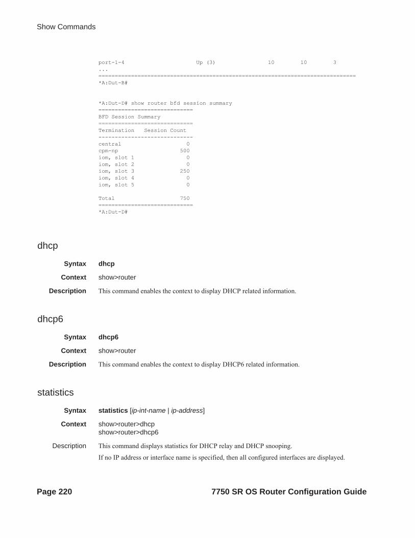
Show Commands
port-1-4 Up (3) 10 10 3...===============================================================================*A:Dut-B#
*A:Dut-D# show router bfd session summary=============================BFD Session Summary=============================Termination Session Count-----------------------------central 0cpm-np 500iom, slot 1 0iom, slot 2 0iom, slot 3 250iom, slot 4 0iom, slot 5 0
Total 750=============================*A:Dut-D#
dhcp
Syntax dhcp
Context show>router
Description This command enables the context to display DHCP related information.
dhcp6
Syntax dhcp6
Context show>router
Description This command enables the context to display DHCP6 related information.
statistics
Syntax statistics [ip-int-name | ip-address]
Context show>router>dhcpshow>router>dhcp6
Description This command displays statistics for DHCP relay and DHCP snooping.
If no IP address or interface name is specified, then all configured interfaces are displayed.
Page 220 7750 SR OS Router Configuration Guide

IP Router Configuration
If an IP address or interface name is specified, then only data regarding the specified interface is displayed.
Parameters ip-int-name | ip-address — Displays statistics for the specified IP interface.
Output Show DHCP Statistics Output — The following table describes the output fields for DHCP. statistics.
Sample Output
A:ALA-1# show router dhcp6 statistics==========================================================================DHCP6 statistics (Router: Base)==========================================================================Msg-type Rx Tx Dropped --------------------------------------------------------------------------1 SOLICIT 0 0 0 2 ADVERTISE 0 0 0 3 REQUEST 0 0 0 4 CONFIRM 0 0 0 5 RENEW 0 0 0 6 REBIND 0 0 0
Label Description
Received Packets The number of packets received from the DHCP clients.
Transmitted Pack-ets
The number of packets transmitted to the DHCP clients.
Received Mal-formed Packets
The number of malformed packets received from the DHCP clients.
Received Untrusted Packets
The number of untrusted packets received from the DHCP clients.
Client Packets Discarded
The number of packets received from the DHCP clients that were dis-carded.
Client Packets Relayed
The number of packets received from the DHCP clients that were for-warded.
Client Packets Snooped
The number of packets received from the DHCP clients that were snooped.
Server Packets Discarded
The number of packets received from the DHCP server that were dis-carded.
Server Packets Relayed
The number of packets received from the DHCP server that were for-warded.
Server Packets Snooped
The number of packets received from the DHCP server that were snooped.
7750 SR OS Router Configuration Guide Page 221

Show Commands
7 REPLY 0 0 0 8 RELEASE 0 0 0 9 DECLINE 0 0 0 10 RECONFIGURE 0 0 0 11 INFO_REQUEST 0 0 0 12 RELAY_FORW 0 0 0 13 RELAY_REPLY 0 0 0 --------------------------------------------------------------------------Dhcp6 Drop Reason Counters :-------------------------------------------------------------------------- 1 Dhcp6 oper state is not Up on src itf 0 2 Dhcp6 oper state is not Up on dst itf 0 3 Relay Reply Msg on Client Itf 0 4 Hop Count Limit reached 0 5 Missing Relay Msg option, or illegal msg type 0 6 Unable to determine destinatinon client Itf 0 7 Out of Memory 0 8 No global Pfx on Client Itf 0 9 Unable to determine src Ip Addr 010 No route to server 011 Subscr. Mgmt. Update failed 012 Received Relay Forw Message 013 Packet too small to contain valid dhcp6 msg 014 Server cannot respond to this message 015 No Server Id option in msg from server 016 Missing or illegal Client Id option in client msg 017 Server Id option in client msg 018 Server DUID in client msg does not match our own 019 Client sent message to unicast while not allowed 020 Client sent message with illegal src Ip address 021 Client message type not supported in pfx delegation 022 Nbr of addrs or pfxs exceeds allowed max (128) in msg 023 Unable to resolve client's mac address 024 The Client was assigned an illegal address 025 Illegal msg encoding 0==========================================================================A:ALA-1#
summary
Syntax summary
Context show>router>dhcp
Description Display the status of the DHCP Relay and DHCP Snooping functions on each interface.
Output Show DHCP Summary Output — The following table describes the output fields for DHCP summary.
Label Description
Interface Name Name of the router interface.
Info Option Indicates whether Option 82 processing is enabled on the interface.
Page 222 7750 SR OS Router Configuration Guide

IP Router Configuration
Sample Output
A:ALA-1# show router dhcp summary===============================================================================DHCP6 Summary (Router: Base)===============================================================================Interface Name Nbr Used/Max Relay Admin Oper Relay SapId Resol. Used/Max Server Admin Oper Server-------------------------------------------------------------------------------interfaceServiceDefault No 0/0 Up NoServerCo* sap:1/2/12:1 0/8000 Up Up interfaceService No 0/0 Down Down sap:1/2/1 0/8000 Down Down interfaceServiceNonDefault No 0/0 Up NoServerCo* sap:1/2/12:2 0/8000 Down Down ip-61.4.113.4 Yes 575/8000 Up Up sap:1/1/1:1 580/8000 Up Up =============================================================================A:ALA-1#
ecmp
Syntax ecmp
Context show>router
Description This command displays the ECMP settings for the router.
Output ECMP Settings Output — The following table describes the output fields for the router ECMP settings.
Auto Filter Indicates whether IP Auto Filter is enabled on the interface.
Snoop Indicates whether Auto ARP table population is enabled on the interface.
Interfaces Indicates the total number of router interfaces on the router.
Label Description
Instance The router instance number.
Router Name The name of the router instance.
ECMP False — ECMP is disabled for the instance.
True — ECMP is enabled for the instance.
Configured-ECMP-Routes The number of ECMP routes configured for path sharing.
7750 SR OS Router Configuration Guide Page 223
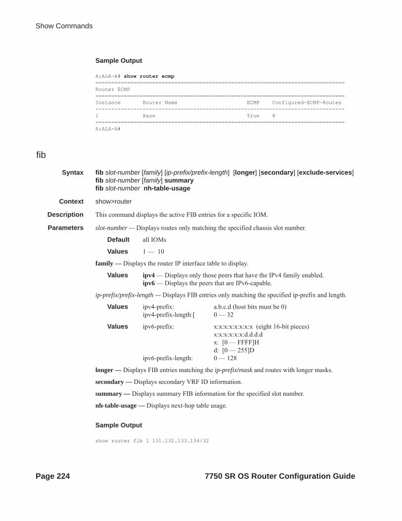
Show Commands
Sample Output
A:ALA-A# show router ecmp===============================================================================Router ECMP ===============================================================================Instance Router Name ECMP Configured-ECMP-Routes -------------------------------------------------------------------------------1 Base True 8 ===============================================================================A:ALA-A#
fib
Syntax fib slot-number [family] [ip-prefix/prefix-length] [longer] [secondary] [exclude-services]fib slot-number [family] summary fib slot-number nh-table-usage
Context show>router
Description This command displays the active FIB entries for a specific IOM.
Parameters slot-number — Displays routes only matching the specified chassis slot number.
Default all IOMs
Values 1 — 10
family — Displays the router IP interface table to display.
Values ipv4 — Displays only those peers that have the IPv4 family enabled.ipv6 — Displays the peers that are IPv6-capable.
ip-prefix/prefix-length — Displays FIB entries only matching the specified ip-prefix and length.
Values ipv4-prefix: a.b.c.d (host bits must be 0)ipv4-prefix-length:[ 0 — 32
Values ipv6-prefix: x:x:x:x:x:x:x:x (eight 16-bit pieces)x:x:x:x:x:x:d.d.d.dx: [0 — FFFF]Hd: [0 — 255]D
ipv6-prefix-length: 0 — 128
longer — Displays FIB entries matching the ip-prefix/mask and routes with longer masks.
secondary — Displays secondary VRF ID information.
summary — Displays summary FIB information for the specified slot number.
nh-table-usage — Displays next-hop table usage.
Sample Output
show router fib 1 131.132.133.134/32
Page 224 7750 SR OS Router Configuration Guide

IP Router Configuration
========================================================================FIB Display========================================================================Prefix Protocol NextHop------------------------------------------------------------------------131.132.133.134/32 OSPF 66.66.66.66 (loop7) Next-hop type: tunneled, Owner: RSVP, Tunnel-ID: <out-ifindex-from-route>------------------------------------------------------------------------Total Entries : 1------------------------------------------------------------------------========================================================================
*A:Dut-C# show router fib 1 1.1.1.1/32===============================================================================FIB Display===============================================================================Prefix Protocol NextHop-------------------------------------------------------------------------------1.1.1.1/32 BGP 10.20.1.1 (Transport:RSVP LSP:1)-------------------------------------------------------------------------------Total Entries : 1-------------------------------------------------------------------------------===============================================================================*A:Dut-C# show router fib 1 ===============================================================================FIB Display===============================================================================Prefix Protocol NextHop -------------------------------------------------------------------------------1.1.2.0/24 ISIS 1.1.3.1 (to_Dut-A) 1.2.3.2 (to_Dut-B) 1.1.3.0/24 LOCAL 1.1.3.0 (to_Dut-A) 1.1.9.0/24 ISIS 1.1.3.1 (to_Dut-A) 1.2.3.0/24 LOCAL 1.2.3.0 (to_Dut-B) 1.2.9.0/24 ISIS 1.2.3.2 (to_Dut-B) 10.12.0.0/24 LOCAL 10.12.0.0 (itfToArborCP_02) 10.20.1.1/32 ISIS 1.1.3.1 (to_Dut-A) 10.20.1.2/32 ISIS 1.2.3.2 (to_Dut-B) 10.20.1.3/32 LOCAL 10.20.1.3 (system) 20.12.0.43/32 STATIC vprn1:mda-1-120.12.0.44/32 STATIC vprn1:mda-2-120.12.0.45/32 STATIC vprn1:mda-2-2
7750 SR OS Router Configuration Guide Page 225

Show Commands
20.12.0.46/32 STATIC vprn1:mda-3-1100.0.0.1/32 TMS vprn1:mda-1-1 vprn1:mda-3-1138.203.71.202/32 STATIC 10.12.0.2 (itfToArborCP_02) -------------------------------------------------------------------------------Total Entries : 15-------------------------------------------------------------------------------===============================================================================
Page 226 7750 SR OS Router Configuration Guide

IP Router Configuration
fp-tunnel-table
Syntax fp-tunnel-table slot-number [ip-prefix/prefix-length]
Context show>router
Description This command displays the IOM/IMM label, next-hop and outgoing interface information for BGP, LDP and RSVP tunnels used in any of the following applications:
• BGP shortcut (configure>router>bgp>igp-shortcut)
• IGP shortcut (config>router>isis[ospf]>rsvp-shortcut)
• IGP prefix resolved to an LDP LSP (config>router>ldp-shortcut)
• Static prefix shortcut
• VPRN auto-bind
• 6PE/6VPE.
Parameters slot-number — Displays information for the specified slot.
Values 1 — 10
ip-prefix[/prefix-length] — Displays routes only matching the specified ip-address and length.
Values ipv4-prefix: a.b.c.d (host bits must be set to 0)ipv4-prefix-length: 0 — 32ipv6 ipv6-prefix[/pref*: x:x:x:x:x:x:x:x (eight 16-bit pieces)
x:x:x:x:x:x:d.d.d.dx: [0 — FFFF]Hd: [0 — 255]D
prefix-length: 1 — 128ipv6
icmp6
Syntax icmp6
Context show>router
Description This command displays Internet Control Message Protocol Version 6 (ICMPv6) statistics. ICMP generates error messages (for example, ICMP destination unreachable messages) to report errors during processing and other diagnostic functions. ICMPv6 packets can be used in the neighbor discovery protocol and path MTU discovery.
Output icmp6 Output — The following table describes the show router icmp6 output fields:
Label Description
Total The total number of all messages.
Destination Unreachable
The number of message that did not reach the destination.
7750 SR OS Router Configuration Guide Page 227

Show Commands
Sample Output
A:SR-3>show>router>auth# show router icmp6 ===============================================================================Global ICMPv6 Stats===============================================================================ReceivedTotal : 14 Errors : 0 Destination Unreachable : 5 Redirects : 5 Time Exceeded : 0 Pkt Too Big : 0 Echo Request : 0 Echo Reply : 0 Router Solicits : 0 Router Advertisements : 4 Neighbor Solicits : 0 Neighbor Advertisements : 0 -------------------------------------------------------------------------------SentTotal : 10 Errors : 0 Destination Unreachable : 0 Redirects : 0 Time Exceeded : 0 Pkt Too Big : 0 Echo Request : 0 Echo Reply : 0 Router Solicits : 0 Router Advertisements : 0 Neighbor Solicits : 5 Neighbor Advertisements : 5 ===============================================================================A:SR-3>show>router>auth#
Time Exceeded The number of messages that exceeded the time threshold.
Echo Request The number of echo requests.
Router Solicits The number of times the local router was solicited.
Neighbor Solicits The number of times the neighbor router was solicited.
Errors The number of error messages.
Redirects The number of packet redirects.
Pkt Too big The number of packets that exceed appropriate size.
Echo Reply The number of echo replies.
Router Advertise-ments
The number of times the router advertised its location.
Neighbor Adver-tisements
The number of times the neighbor router advertised its location.
Label Description (Continued)
Page 228 7750 SR OS Router Configuration Guide

IP Router Configuration
interface
Syntax interface [interface-name]
Context show>router>icmpv6
Description This command displays interface ICMPv6 statistics.
Parameters interface-name — Only displays entries associated with the specified IP interface name.
Output icmp6 interface Output — The following table describes the show router icmp6 interface output fields:
Sample Output
B:CORE2# show router icmp6 interface net1_1_2 ===============================================================================Interface ICMPv6 Stats===============================================================================Interface "net1_1_2"-------------------------------------------------------------------------------ReceivedTotal : 41 Errors : 0 Destination Unreachable : 0 Redirects : 0 Time Exceeded : 0 Pkt Too Big : 0 Echo Request : 0 Echo Reply : 0
Label Description
Total The total number of all messages.
Destination Unreachable
The number of message that did not reach the destination.
Time Exceeded The number of messages that exceeded the time threshold.
Echo Request The number of echo requests.
Router Solicits The number of times the local router was solicited.
Neighbor Solicits The number of times the neighbor router was solicited.
Errors The number of error messages.
Redirects The number of packet redirects.
Pkt Too big The number of packets that exceed appropriate size.
Echo Reply The number of echo replies.
Router Advertise-ments
The number of times the router advertised its location.
Neighbor Adver-tisements
The number of times the neighbor router advertised its location.
7750 SR OS Router Configuration Guide Page 229

Show Commands
Router Solicits : 0 Router Advertisements : 0 Neighbor Solicits : 20 Neighbor Advertisements : 21 -------------------------------------------------------------------------------SentTotal : 47 Errors : 0 Destination Unreachable : 0 Redirects : 0 Time Exceeded : 0 Pkt Too Big : 0 Echo Request : 0 Echo Reply : 0 Router Solicits : 0 Router Advertisements : 0 Neighbor Solicits : 27 Neighbor Advertisements : 20 ===============================================================================B:CORE2#
interface
Syntax interface [{[ip-address|ip-int-name][detail] [family]}|summary| exclude-services]interface ip-address|ip-int-name eth-cfm [detail]interface ip-address|ip-int-name mac [ieee-address]interface ip-address|ip-int-name statisticsinterface dist-cpu-protection [detail]interface policy-accounting [class [index]]
Context show>router
Description This command displays the router IP interface table sorted by interface index.
Parameters ip-address — Only displays the interface information associated with the specified IP address.
Values ipv4-address a.b.c.d (host bits must be 0)ipv6-address x:x:x:x:x:x:x:x (eight 16-bit pieces)
x:x:x:x:x:x:d.d.d.d x: [0 — FFFF]H d: [0 — 255]D
ip-int-name — Only displays the interface information associated with the specified IP interface name.
detail — Displays detailed IP interface information.
statistics — Displays packet statistics for an interface on the router.
summary — Displays summary IP interface information for the router.
exclude-services — Displays IP interface information, excluding IP interfaces configured for customer services. Only core network IP interfaces are displayed.
family — Specifies the router IP interface family to display.
Values ipv4 — Displays only those peers that have the IPv4 family enabled.Values ipv6 — Displays the peers that are IPv6-capable.
Output Standard IP Interface Output — The following table describes the standard output fields for an IP interface.
Page 230 7750 SR OS Router Configuration Guide
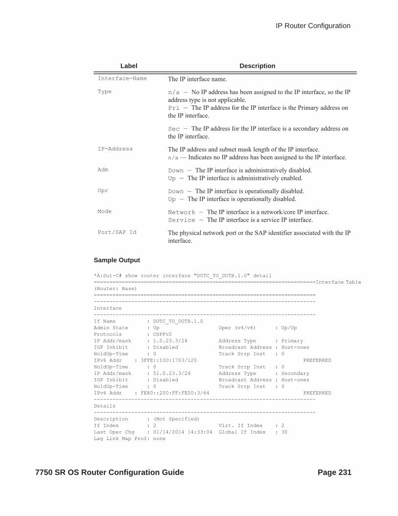
IP Router Configuration
Sample Output
*A:Dut-C# show router interface "DUTC_TO_DUTB.1.0" detail =======================================================================Interface Table (Router: Base)=======================================================================-----------------------------------------------------------------------Interface-----------------------------------------------------------------------If Name : DUTC_TO_DUTB.1.0Admin State : Up Oper (v4/v6) : Up/UpProtocols : OSPFv2 IP Addr/mask : 1.0.23.3/24 Address Type : PrimaryIGP Inhibit : Disabled Broadcast Address : Host-onesHoldUp-Time : 0 Track Srrp Inst : 0IPv6 Addr : 3FFE::100:1703/120 PREFERREDHoldUp-Time : 0 Track Srrp Inst : 0IP Addr/mask : 51.0.23.3/24 Address Type : SecondaryIGP Inhibit : Disabled Broadcast Address : Host-onesHoldUp-Time : 0 Track Srrp Inst : 0IPv6 Addr : FE80::200:FF:FE00:3/64 PREFERRED-----------------------------------------------------------------------Details-----------------------------------------------------------------------Description : (Not Specified)If Index : 2 Virt. If Index : 2Last Oper Chg : 01/14/2014 14:33:04 Global If Index : 30Lag Link Map Prof: none
Label Description
Interface-Name The IP interface name.
Type n/a — No IP address has been assigned to the IP interface, so the IP address type is not applicable.Pri — The IP address for the IP interface is the Primary address on the IP interface.
Sec — The IP address for the IP interface is a secondary address on the IP interface.
IP-Address The IP address and subnet mask length of the IP interface. n/a — Indicates no IP address has been assigned to the IP interface.
Adm Down — The IP interface is administratively disabled.Up — The IP interface is administratively enabled.
Opr Down — The IP interface is operationally disabled.Up — The IP interface is operationally disabled.
Mode Network — The IP interface is a network/core IP interface.Service — The IP interface is a service IP interface.
Port/SAP Id The physical network port or the SAP identifier associated with the IP interface.
7750 SR OS Router Configuration Guide Page 231

Show Commands
Port Id : 1/1/2:1TOS Marking : Trusted If Type : NetworkEgress Filter : none Ingress Filter : noneEgr IPv6 Flt : none Ingr IPv6 Flt : noneBGP IP FlowSpec : DisabledBGP IPv6 FlowSpec: DisabledSNTP B.Cast : False QoS Policy : 1Queue-group : None MAC Address : 00:00:00:00:00:03 Mac Accounting : DisabledIngress stats : Disabled IPv6 DAD : EnabledTCP MSS V4 : 0 TCP MSS V6 : 0Arp Timeout : 14400 IPv6 Nbr ReachTime: 30 IPv6 stale time(s): 14400IP Oper MTU : 1500 ICMP Mask Reply : TrueArp Populate : Disabled Cflowd : None LdpSyncTimer : None Strip-Label : DisabledLSR Load Balance : system EGR Load Balance : both TEID Load Balance: Disabled uRPF Chk : disabled uRPF Ipv6 Chk : disabled PTP HW Assist : Disabled Rx Pkts : N/A Rx Bytes : N/ARx V4 Pkts : N/A Rx V4 Bytes : N/ARx V6 Pkts : N/A Rx V6 Bytes : N/ATx Pkts : 410 Tx Bytes : 40204Tx V4 Pkts : 408 Tx V4 Bytes : 40032Tx V4 Discard Pk*: 0 Tx V4 Discard Byt*: 0Tx V6 Pkts : 2 Tx V6 Bytes : 172Tx V6 Discard Pk*: 0 Tx V6 Discard Byt*: 0
Proxy ARP DetailsRem Proxy ARP : Disabled Local Proxy ARP : DisabledPolicies : none
Proxy Neighbor Discovery DetailsLocal Pxy ND : Disabled Policies : none
Secure ND DetailsSecure ND : Disabled
ICMP DetailsRedirects : Number - 100 Time (seconds) - 10 Unreachables : Number - 100 Time (seconds) - 10 TTL Expired : Number - 100 Time (seconds) - 10
IPCP Address Extension DetailsPeer IP Addr : Not configured Peer Pri DNS Addr: Not configured Peer Sec DNS Addr: Not configured Network Domains Associateddefault
----------------------------------------------------------------------Admin Groups----------------------------------------------------------------------
Page 232 7750 SR OS Router Configuration Guide

IP Router Configuration
"group1" "group2" ----------------------------------------------------------------------
----------------------------------------------------------------------Srlg Groups----------------------------------------------------------------------"group3" "group4" ---------------------------------------------------------------------------------------------------------------------------------------------Qos Details-----------------------------------------------------------------------Ing Qos Policy : (none) Egr Qos Policy : (none)Ingress FP QGrp : (none) Egress Port QGrp : (none)Ing FP QGrp Inst : (none) Egr Port QGrp Inst: (none)=======================================================================* indicates that the corresponding row element may have been truncated.*A:Dut-C#
*A:mlstp-dutA# show router interface "AtoB_1"===============================================================================Interface Table (Router: Base)===============================================================================Interface-Name Adm Opr(v4/v6) Mode Port/SapId IP-Address PfxState-------------------------------------------------------------------------------AtoB_1 Down Down/-- Network 1/2/3:1 Unnumbered If[system] n/a-------------------------------------------------------------------------------Interfaces : 1
A:ALA-A# show router interface===============================================================================Interface Table (Router: Base)===============================================================================Interface-Name Adm(v4/v6) Opr(v4/v6) Mode Port/SapId IP-Address PfxState-------------------------------------------------------------------------------ip-100.0.0.2 Up/Up Up/Up Network lag-1 100.0.0.2/10 n/a 3FFE:1::2/64 PREFERRED FE80::200:FF:FE00:4/64 PREFERREDip-100.128.0.2 Up/Up Up/Up Network lag-2 100.128.0.2/10 n/a 3FFE:2::2/64 PREFERRED FE80::200:FF:FE00:4/64 PREFERREDip-11.2.4.4 Up/Up Down/Down Network 3/1/1 11.2.4.4/24 n/a 15::2/120 ip-11.4.101.4 Up/Up Up/Up Network 5/2/1 11.4.101.4/24 n/a 3FFE::B04:6504/120 PREFERRED FE80::200:FF:FE00:4/64 PREFERREDip-11.4.113.4 Up/Up Up/Up Network 6/1/1 11.4.113.4/24 n/a 3FFE::B04:7104/120 PREFERRED FE80::200:FF:FE00:4/64 PREFERRED
7750 SR OS Router Configuration Guide Page 233
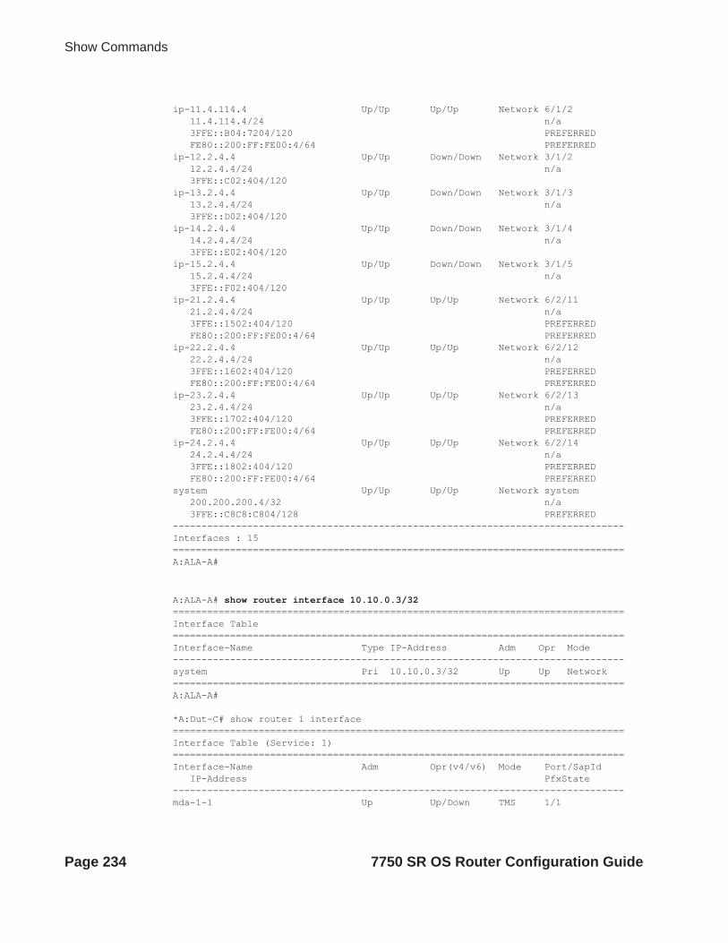
Show Commands
ip-11.4.114.4 Up/Up Up/Up Network 6/1/2 11.4.114.4/24 n/a 3FFE::B04:7204/120 PREFERRED FE80::200:FF:FE00:4/64 PREFERREDip-12.2.4.4 Up/Up Down/Down Network 3/1/2 12.2.4.4/24 n/a 3FFE::C02:404/120 ip-13.2.4.4 Up/Up Down/Down Network 3/1/3 13.2.4.4/24 n/a 3FFE::D02:404/120 ip-14.2.4.4 Up/Up Down/Down Network 3/1/4 14.2.4.4/24 n/a 3FFE::E02:404/120 ip-15.2.4.4 Up/Up Down/Down Network 3/1/5 15.2.4.4/24 n/a 3FFE::F02:404/120 ip-21.2.4.4 Up/Up Up/Up Network 6/2/11 21.2.4.4/24 n/a 3FFE::1502:404/120 PREFERRED FE80::200:FF:FE00:4/64 PREFERREDip-22.2.4.4 Up/Up Up/Up Network 6/2/12 22.2.4.4/24 n/a 3FFE::1602:404/120 PREFERRED FE80::200:FF:FE00:4/64 PREFERREDip-23.2.4.4 Up/Up Up/Up Network 6/2/13 23.2.4.4/24 n/a 3FFE::1702:404/120 PREFERRED FE80::200:FF:FE00:4/64 PREFERREDip-24.2.4.4 Up/Up Up/Up Network 6/2/14 24.2.4.4/24 n/a 3FFE::1802:404/120 PREFERRED FE80::200:FF:FE00:4/64 PREFERREDsystem Up/Up Up/Up Network system 200.200.200.4/32 n/a 3FFE::C8C8:C804/128 PREFERRED-------------------------------------------------------------------------------Interfaces : 15===============================================================================A:ALA-A#
A:ALA-A# show router interface 10.10.0.3/32===============================================================================Interface Table ===============================================================================Interface-Name Type IP-Address Adm Opr Mode -------------------------------------------------------------------------------system Pri 10.10.0.3/32 Up Up Network ===============================================================================A:ALA-A#
*A:Dut-C# show router 1 interface ===============================================================================Interface Table (Service: 1)===============================================================================Interface-Name Adm Opr(v4/v6) Mode Port/SapId IP-Address PfxState-------------------------------------------------------------------------------mda-1-1 Up Up/Down TMS 1/1
Page 234 7750 SR OS Router Configuration Guide

IP Router Configuration
20.12.0.43/32 n/amda-2-1 Up Up/Down TMS 2/1 20.12.0.44/32 n/amda-2-2 Up Up/Down TMS 2/2 20.12.0.45/32 n/amda-3-1 Up Up/Down TMS 3/1 20.12.0.46/32 n/a-------------------------------------------------------------------------------Interfaces : 4===============================================================================A:ALA-A# show router interface to-ser1 ===============================================================================Interface Table ===============================================================================Interface-Name Type IP-Address Adm Opr Mode -------------------------------------------------------------------------------to-ser1 Pri 10.10.13.3/24 Up Up Network ===============================================================================A:ALA-A#A:ALA-A# show router interface exclude-services===============================================================================Interface Table ===============================================================================Interface-Name Type IP-Address Adm Opr Mode -------------------------------------------------------------------------------system Pri 10.10.0.3/32 Up Up Network to-ser1 Pri 10.10.13.3/24 Up Up Network to-ser4 Pri 10.10.34.3/24 Up Up Network to-ser5 Pri 10.10.35.3/24 Up Up Network to-ser6 n/a n/a Up Down Network management Pri 192.168.2.93/20 Up Up Network ===============================================================================A:ALA-A#
Detailed IP Interface Output — The following table describes the detailed output fields for an IP interface.
Label Description
If Name The IP interface name.
Admin State Down — The IP interface is administratively disabled.
Up — The IP interface is administratively enabled.
Oper State Down — The IP interface is operationally disabled.
Up — The IP interface is operationally enabled.
IP Addr/mask The IP address and subnet mask length of the IP interface. Not Assigned — Indicates no IP address has been assigned to the IP interface.
IPV6 Addr The IPv6 address of the interface.
If Index The interface index of the IP router interface.
7750 SR OS Router Configuration Guide Page 235

Show Commands
Sample Output
B:bksim1619# show router interface "to-sim1621" detail===============================================================================
Virt If Index The virtual interface index of the IP router interface.
Last Oper Change The last change in operational status.
Global If Index The global interface index of the IP router interface.
Sap ID The SAP identifier.
TOS Marker The TOS byte value in the logged packet.
If Type Network — The IP interface is a network/core IP interface.
Service — The IP interface is a service IP interface.
SNTP B.cast Displays if the broadcast-client global parameter is configured.
IES ID The IES identifier.
QoS Policy The QoS policy ID associated with the IP interface.
MAC Address The MAC address of the interface.
Arp Timeout The ARP timeout for the interface, in seconds, which is the time an ARP entry is maintained in the ARP cache without being refreshed.
ICMP Mask Reply False — The IP interface will not reply to a received ICMP mask request.True — The IP interface will reply to a received ICMP mask request.
Arp Populate Displays whether ARP is enabled or disabled.
Host Conn Verify The host connectivity verification.
LdpSyncTimer Specifies the IGP/LDP sync timer value.
uRPF Chk Specifies whether unicast RPF (uRPF) Check is enabled on this inter-face.
uRPF Iv6 Chk Specifies whether unicast RPF (uRPF) Check IPv6 is enabled on this interface.
PTP HW Assist Specifies whether the PTP Hardware Assist function is enabled on this interface.
Cflowd Specifies the type of Cflowd analysis that is applied to the interface. acl — ACL Cflowd analysis is applied to the interface.interface — Interface cflowd analysis is applied to the interface.none — No Cflowd analysis is applied to the interface.
Label Description (Continued)
Page 236 7750 SR OS Router Configuration Guide

IP Router Configuration
Interface Table (Router: Base)===============================================================================-------------------------------------------------------------------------------Interface-------------------------------------------------------------------------------If Name : to-sim1621Admin State : Up Oper (v4/v6) : Up/--Protocols : NoneIP Addr/mask : 1.1.1.2/24 Address Type : PrimaryIGP Inhibit : Disabled Broadcast Address : Host-onesHoldUp-Time : 0 Track Srrp Inst : 0-------------------------------------------------------------------------------Details-------------------------------------------------------------------------------Description : (Not Specified)If Index : 5 Virt. If Index : 5Last Oper Chg : 01/03/2012 13:29:19 Global If Index : 125Port Id : 1/1/1TOS Marking : Trusted If Type : NetworkEgress Filter : none Ingress Filter : noneEgr IPv6 Flt : none Ingr IPv6 Flt : noneBGP FlowSpec : DisabledSNTP B.Cast : False QoS Policy : 1Queue-group : NoneMAC Address : ac:5e:01:01:00:01 Arp Timeout : 14400IP Oper MTU : 1564 ICMP Mask Reply : TrueArp Populate : DisabledCflowd : NoneLdpSyncTimer : None Strip-Label : DisabledLSR Load Balance : systemuRPF Chk : disableduRPF Ipv6 Chk : disabledPTP HW Assist : EnabledRx Pkts : 360899 Rx Bytes : 32482050Tx Pkts : 724654 Tx Bytes : 68885238Tx V4 Pkts : 724654 Tx V4 Bytes : 68885238Tx V4 Discard Pk*: 0 Tx V4 Discard Byt*: 0Tx V6 Pkts : 0 Tx V6 Bytes : 0Tx V6 Discard Pk*: 0 Tx V6 Discard Byt*: 0
Proxy ARP DetailsRem Proxy ARP : Disabled Local Proxy ARP : DisabledPolicies : none
Proxy Neighbor Discovery DetailsLocal Pxy ND : DisabledPolicies : none
ICMP DetailsRedirects : Number - 100 Time (seconds) - 10Unreachables : Number - 100 Time (seconds) - 10TTL Expired : Number - 100 Time (seconds) - 10
IPCP Address Extension DetailsPeer IP Addr : Not configuredPeer Pri DNS Addr: Not configuredPeer Sec DNS Addr: Not configured
Network Domains Associated
7750 SR OS Router Configuration Guide Page 237

Show Commands
default-------------------------------------------------------------------------------Qos Details-------------------------------------------------------------------------------
Ing Qos Policy : (none) Egr Qos Policy : (none)Ingress FP QGrp : (none) Egress Port QGrp : (none)Ing FP QGrp Inst : (none) Egr Port QGrp Inst: (none)===============================================================================* indicates that the corresponding row element may have been truncated.B:bksim1619#
*A:Dut-C# show router 1 interface "mda-3-1" detail ===============================================================================Interface Table (Service: 1)=============================================================================== -------------------------------------------------------------------------------Interface-------------------------------------------------------------------------------If Name : mda-3-1Admin State : Up Oper (v4/v6) : Up/DownProtocols : NoneIP Addr/mask : 20.12.0.46/32 Address Type : PrimaryIGP Inhibit : Disabled Broadcast Address : Host-onesHoldUp-Time : 0 Track Srrp Inst : 0-------------------------------------------------------------------------------Details-------------------------------------------------------------------------------Description : tms-3-1If Index : 5 Virt. If Index : 5Last Oper Chg : 07/08/2011 06:49:45 Global If Index : 95If Type : TMS Rx Pkts : 14935 Rx Bytes : 955840Tx Pkts : 14892 Tx Bytes : 953088Tx Discard Pkts : 0
TMS Health InformationStatus : UpVersion : Peakflow TMS 5.6 (build BF42)Mitigations : 1Status message : (Unavailable)===============================================================================*A:Dut-C# show router 1 interface "mda-2-1" detail
===============================================================================Interface Table (Service: 1)=============================================================================== -------------------------------------------------------------------------------Interface-------------------------------------------------------------------------------If Name : mda-2-1Admin State : Up Oper (v4/v6) : Up/DownProtocols : NoneIP Addr/mask : 20.12.0.44/32 Address Type : Primary
Page 238 7750 SR OS Router Configuration Guide

IP Router Configuration
IGP Inhibit : Disabled Broadcast Address : Host-onesHoldUp-Time : 0 Track Srrp Inst : 0-------------------------------------------------------------------------------Details-------------------------------------------------------------------------------Description : tms-2-1If Index : 3 Virt. If Index : 3Last Oper Chg : 09/14/2011 08:39:24 Global If Index : 122If Type : TMS Rx Pkts : 13508 Rx Bytes : 864512Tx Pkts : 13552 Tx Bytes : 867328Tx Discard Pkts : 0
TMS Health InformationStatus : UpVersion : Peakflow TMS 5.6 (build BHDF)Mitigations : 1Status message : (Unavailable)===============================================================================with Rx Pkts/Rx Bytes: Offramped traffic counters Tx Pkts/Tx Bytes: Onramped traffic counters Tx Discard Pkts: Discarded packets by TMSIt displays the #of pkts dropped while the traffic is getting distributed to various It doesn't account for the pkts dropped in HW level. Status: TMS status could be Up/Down Version: TMS software version Mitigations: Number of active mitigations on this TMS Status message: Not applicable. For future usage===============================================================================
Statistics IP Interface Output — The following table describes the packet statistics for the router IP interfaces.
Sample Output
The following displays output if enable-interface-statistics is enabled for a given interface.A:ALA-A# show router interface “to_ixia” statistics ===============================================================================Interface Statistics===============================================================================If Name : to_IxiaAdmin State : Up Oper (v4/v6) : Up/UpRx Pkts : 6244 Rx Bytes : 599424Rx V4 Pkts : 3122 Rx V4 Bytes : 299712Rx V6 Pkts : 3122 Rx V6 Bytes : 299712
Label Description
Ifname The interface name.
Admin State The administrative status of the router interface.
Oper The operational status of the router instance.
7750 SR OS Router Configuration Guide Page 239

Show Commands
Tx Pkts : 0 Tx Bytes : 0Tx V4 Pkts : 0 Tx V4 Bytes : 0Tx V4 Discard Pk*: 0 Tx V4 Discard Byt*: 0Tx V6 Pkts : 0 Tx V6 Bytes : 0Tx V6 Discard Pk*: 0 Tx V6 Discard Byt*: 0uRPF Chk Fail Pk*: 6244 uRPF Fail Bytes : 487032uRPF Fail V4 Pk : 3122 uRPF Fail V4 Byt : 243516uRPF Fail V6 Pk : 3122 uRPF Fail V6 Byt : 243516===============================================================================
*A:Dut-C# show router interface "to_Ixia" detail===============================================================================Interface Table (Router: Base)===============================================================================-------------------------------------------------------------------------------Interface-------------------------------------------------------------------------------If Name : to_IxiaAdmin State : Up Oper (v4/v6) : Up/UpProtocols : NoneIP Addr/mask : 1.3.9.3/24 Address Type : PrimaryIGP Inhibit : Disabled Broadcast Address : Host-onesHoldUp-Time : 0 Track Srrp Inst : 0IPv6 Addr : 3FFE::103:903/120 PREFERREDHoldUp-Time : 0 Track Srrp Inst : 0IPv6 Addr : FE80::200:FF:FE00:3/64 PREFERRED-------------------------------------------------------------------------------Details-------------------------------------------------------------------------------Description : (Not Specified)If Index : 3 Virt. If Index : 3Last Oper Chg : 01/27/2014 16:42:40 Global If Index : 19Lag Link Map Prof: nonePort Id : 1/1/4TOS Marking : Trusted If Type : NetworkEgress Filter : none Ingress Filter : noneEgr IPv6 Flt : none Ingr IPv6 Flt : noneBGP IP FlowSpec : DisabledBGP IPv6 FlowSpec: DisabledSNTP B.Cast : False QoS Policy : 1Queue-group : NoneMAC Address : 00:00:00:00:00:03 Mac Accounting : DisabledIngress stats : Enabled IPv6 DAD : EnabledTCP MSS V4 : 0 TCP MSS V6 : 0Arp Timeout : 14400 IPv6 Nbr ReachTime: 30 IPv6 stale time(s): 14400IP Oper MTU : 1500 ICMP Mask Reply : TrueArp Populate : DisabledCflowd : NoneLdpSyncTimer : None Strip-Label : DisabledLSR Load Balance : systemEGR Load Balance : bothTEID Load Balance: DisableduRPF Chk : enabled uRPF Chk Mode : strictuRPF Ipv6 Chk : enabled uRPF Ipv6 Chk Mode: strictPTP HW Assist : DisabledRx Pkts : 6244 Rx Bytes : 599424
Page 240 7750 SR OS Router Configuration Guide

IP Router Configuration
Rx V4 Pkts : 3122 Rx V4 Bytes : 299712Rx V6 Pkts : 3122 Rx V6 Bytes : 299712Tx Pkts : 0 Tx Bytes : 0Tx V4 Pkts : 0 Tx V4 Bytes : 0Tx V4 Discard Pk*: 0 Tx V4 Discard Byt*: 0Tx V6 Pkts : 0 Tx V6 Bytes : 0Tx V6 Discard Pk*: 0 Tx V6 Discard Byt*: 0uRPF Chk Fail Pk*: 6244 uRPF Fail Bytes : 487032uRPF Fail V4 Pk : 3122 uRPF Fail V4 Byt : 243516uRPF Fail V6 Pk : 3122 uRPF Fail V6 Byt : 243516
Proxy ARP DetailsRem Proxy ARP : Disabled Local Proxy ARP : DisabledPolicies : none
Proxy Neighbor Discovery DetailsLocal Pxy ND : DisabledPolicies : none
Secure ND DetailsSecure ND : Disabled
ICMP DetailsRedirects : Number - 100 Time (seconds) - 10Unreachables : Number - 100 Time (seconds) - 10TTL Expired : Number - 100 Time (seconds) - 10
IPCP Address Extension DetailsPeer IP Addr : Not configuredPeer Pri DNS Addr: Not configuredPeer Sec DNS Addr: Not configured
Network Domains Associateddefault----------------------------------------------------------------------Admin Groups----------------------------------------------------------------------No Matching Entries--------------------------------------------------------------------------------------------------------------------------------------------Srlg Groups----------------------------------------------------------------------No Matching Entries-----------------------------------------------------------------------------------------------------------------------------------------------------Qos Details-------------------------------------------------------------------------------Ing Qos Policy : (none) Egr Qos Policy : (none)Ingress FP QGrp : (none) Egress Port QGrp : (none)Ing FP QGrp Inst : (none) Egr Port QGrp Inst: (none)===============================================================================* indicates that the corresponding row element may have been truncated.
The following displays output if enable-interface-statistics is not enabled for a given interface.===============================================================================Interface Statistics===============================================================================
7750 SR OS Router Configuration Guide Page 241

Show Commands
If Name : to_IxiaAdmin State : Up Oper (v4/v6) : Up/UpRx Pkts : N/A Rx Bytes : N/ARx V4 Pkts : N/A Rx V4 Bytes : N/ARx V6 Pkts : N/A Rx V6 Bytes : N/ATx Pkts : 0 Tx Bytes : 0Tx V4 Pkts : 0 Tx V4 Bytes : 0Tx V4 Discard Pk*: 0 Tx V4 Discard Byt*: 0Tx V6 Pkts : 0 Tx V6 Bytes : 0Tx V6 Discard Pk*: 0 Tx V6 Discard Byt*: 0uRPF Chk Fail Pk*: 0 uRPF Fail Bytes : 0uRPF Fail V4 Pk : 0 uRPF Fail V4 Byt : 0uRPF Fail V6 Pk : 0 uRPF Fail V6 Byt : 0===============================================================================* indicates that the corresponding row element may have been truncated.
Page 242 7750 SR OS Router Configuration Guide

IP Router Configuration
*A:Dut-C# show router 1 interface "mda-3-1" detail===============================================================================Interface Table (Service: 1)===============================================================================-------------------------------------------------------------------------------Interface-------------------------------------------------------------------------------If Name : mda-3-1Admin State : Up Oper (v4/v6) : Up/DownProtocols : NoneIP Addr/mask : 20.12.0.46/32 Address Type : PrimaryIGP Inhibit : Disabled Broadcast Address : Host-onesHoldUp-Time : 0 Track Srrp Inst : 0-------------------------------------------------------------------------------Details-------------------------------------------------------------------------------Description : tms-3-1If Index : 5 Virt. If Index : 5Last Oper Chg : 07/08/2011 06:49:45 Global If Index : 95If Type : TMS Rx Pkts : 14935 Rx Bytes : 955840Tx Pkts : 14892 Tx Bytes : 953088Tx Discard Pkts : 0
TMS Health InformationStatus : UpVersion : Peakflow TMS 5.6 (build BF42)Mitigations : 1Status message : (Unavailable)===============================================================================
Summary IP Interface Output — The following table describes the summary output fields for the router IP interfaces..
Sample Output
A:ALA-A# show router interface summary===============================================================================Router Summary (Interfaces) ===============================================================================Instance Router Name Interfaces Admin-Up Oper-Up -------------------------------------------------------------------------------
Label Description
Instance The router instance number.
Router Name The name of the router instance.
Interfaces The number of IP interfaces in the router instance.
Admin-Up The number of administratively enabled IP interfaces in the router instance.
Oper-Up The number of operationally enabled IP interfaces in the router instance.
7750 SR OS Router Configuration Guide Page 243

Show Commands
1 Base 7 7 5 ===============================================================================
routes
Syntax routes alternative
Context show:router>isis
Description This command displays IS-IS route information.
Sample Output
*A:SRR# show router isis routes 1.1.1.0/24 ===============================================================================Route Table===============================================================================Prefix[Flags] Metric Lvl/Typ Ver. SysID/Hostname NextHop MT AdminTag -------------------------------------------------------------------------------1.1.1.0/24 [L] 7540 1/Int. 6109 SRL 60.60.1.1 0 0-------------------------------------------------------------------------------No. of Routes: 1Flags: L = LFA nexthop available===============================================================================*A:SRR# *A:SRR# show router isis routes 1.1.1.0/24 alternative ===============================================================================Route Table===============================================================================Prefix[Flags] Metric Lvl/Typ Ver. SysID/Hostname NextHop MT AdminTag Alt-Nexthop Alt-Metric Alt-Type -------------------------------------------------------------------------------1.1.1.0/24 7550 1/Int. 6114 SRL 60.60.1.1 0 0 11.22.12.4 (LFA) 16784764 linkProtection-------------------------------------------------------------------------------No. of Routes: 1Flags: LFA = Loop-Free Alternate nexthop===============================================================================*A:SRR#
*A:Dut-B# show router isis routes============================================================================Route Table============================================================================Prefix [Flags] Metric Lvl/Typ Ver. SysID/Hostname NextHop MT AdminTag----------------------------------------------------------------------------10.20.1.2/32 0 1/Int. 3 Dut-B 0.0.0.0 0 010.20.1.3/32 [L] 10 2/Int. 2 Dut-C 10.20.3.3 0 0
Page 244 7750 SR OS Router Configuration Guide

IP Router Configuration
10.20.1.4/32 10 2/Int. 3 Dut-D 10.20.4.4 0 010.20.1.5/32 20 2/Int. 3 Dut-C 10.20.3.3 0 010.20.1.6/32 20 2/Int. 3 Dut-D 10.20.4.4 0 010.20.3.0/24 10 1/Int. 3 Dut-B 0.0.0.0 0 010.20.4.0/24 10 1/Int. 3 Dut-B 0.0.0.0 0 010.20.5.0/24 20 2/Int. 2 Dut-C 10.20.3.3 0 010.20.6.0/24 20 2/Int. 4 Dut-D 10.20.4.4 0 010.20.9.0/24 20 2/Int. 3 Dut-D 10.20.4.4 0 010.20.10.0/24 30 2/Int. 3 Dut-C 10.20.3.3 0 0----------------------------------------------------------------------------Routes : 11Flags: L = LFA nexthop available ============================================================================*A:Dut-B#
*A:Dut-B# show router isis routes alternative
============================================================================Route Table============================================================================Prefix [Flags] Metric Lvl/Typ Ver. SysID/Hostname NextHop MT AdminTagAlt-Nexthop Alt-Metric----------------------------------------------------------------------------10.20.1.2/32 0 1/Int. 3 Dut-B 0.0.0.0 0 010.20.1.3/32 10 2/Int. 2 Dut-C 10.20.3.3 0 0 10.20.3.3 (lfa) 1510.20.1.4/32 10 2/Int. 3 Dut-D 10.20.4.4 0 010.20.1.5/32 20 2/Int. 3 Dut-C 10.20.3.3 0 010.20.1.6/32 20 2/Int. 3 Dut-D 10.20.4.4 0 010.20.3.0/24 10 1/Int. 3 Dut-B 0.0.0.0 0 010.20.4.0/24 10 1/Int. 3 Dut-B 0.0.0.0 0 010.20.5.0/24 20 2/Int. 2 Dut-C 10.20.3.3 0 010.20.6.0/24 20 2/Int. 4 4 Dut-D 10.20.4.4 0 010.20.9.0/24 20 2/Int. 3 Dut-D 10.20.4.4 0 010.20.10.0/24 30 2/Int. 3 Dut-C 10.20.3.3 0 0----------------------------------------------------------------------------Routes : 11
7750 SR OS Router Configuration Guide Page 245

Show Commands
Flags: LFA = Loop-Free Alternate nexthop============================================================================*A:Dut-B#
bindings
Syntax bindings active
Context show>router>ldp
Description This command displays LDP bindings information.
Sample Output
*A:Dut-A# show router ldp bindings active
========================================================================Legend: (S) - Static (M) - Multi-homed Secondary Support (B) - BGP Next Hop (BU) - Alternate Next-hop for Fast Re-Route========================================================================LDP Prefix Bindings (Active)========================================================================Prefix Op IngLbl EgrLbl EgrIntf/LspId EgrNextHop------------------------------------------------------------------------10.20.1.1/32 Pop 131071 -- -- --10.20.1.2/32 Push -- 131071 1/1/1 10.10.1.210.20.1.2/32 Swap 131070 131071 1/1/1 10.10.1.210.20.1.2/32 Push -- 262141BU 1/1/2 10.10.2.310.20.1.2/32 Swap 131070 262141BU 1/1/2 10.10.2.310.20.1.3/32 Push -- 131069BU 1/1/1 10.10.1.210.20.1.3/32 Swap 131069 131069BU 1/1/1 10.10.1.210.20.1.3/32 Push -- 262143 1/1/2 10.10.2.310.20.1.3/32 Swap 131069 262143 1/1/2 10.10.2.310.20.1.4/32 Push -- 131068 1/1/1 10.10.1.210.20.1.4/32 Swap 131068 131068 1/1/1 10.10.1.210.20.1.4/32 Push -- 262140BU 1/1/2 10.10.2.310.20.1.4/32 Swap 131068 262140BU 1/1/2 10.10.2.310.20.1.5/32 Push -- 131067BU 1/1/1 10.10.1.210.20.1.5/32 Swap 131067 131067BU 1/1/1 10.10.1.210.20.1.5/32 Push -- 262139 1/1/2 10.10.2.310.20.1.5/32 Swap 131067 262139 1/1/2 10.10.2.310.20.1.6/32 Push -- 131066 1/1/1 10.10.1.210.20.1.6/32 Swap 131066 131066 1/1/1 10.10.1.210.20.1.6/32 Push -- 262138BU 1/1/2 10.10.2.310.20.1.6/32 Swap 131066 262138BU 1/1/2 10.10.2.3------------------------------------------------------------------------No. of Prefix Active Bindings: 21========================================================================LDP P2MP Bindings (Active)========================================================================P2MP-Id RootAddr Interface Op IngLbl EgrLbl EgrIntf/ EgrNextHop LspId ------------------------------------------------------------------------No Matching Entries Found
Page 246 7750 SR OS Router Configuration Guide

IP Router Configuration
========================================================================
*A:Dut-A# show router ldp bindings
========================================================================LDP LSR ID: 10.20.1.1========================================================================Legend: U - Label In Use, N - Label Not In Use, W - Label Withdrawn S - Status Signaled Up, D - Status Signaled Down E - Epipe Service, V - VPLS Service, M - Mirror Service A - Apipe Service, F - Fpipe Service, I - IES Service, R - VPRN service P - Ipipe Service, WP - Label Withdraw Pending, C - Cpipe Service BU - Alternate Next-hop for Fast Re-Route, TLV - (Type, Length: Value)========================================================================LDP Prefix Bindings========================================================================Prefix Peer IngLbl EgrLbl EgrIntf/ EgrNextHop LspId ------------------------------------------------------------------------10.20.1.1/32 10.20.1.2 131071U -- -- --10.20.1.1/32 10.20.1.3 131071U -- -- --10.20.1.2/32 10.20.1.2 -- 131071 1/1/1 10.10.1.210.20.1.2/32 10.20.1.3 131070U 262141 1/1/2 10.10.2.310.20.1.3/32 10.20.1.2 131069U 131069 1/1/1 10.10.1.210.20.1.3/32 10.20.1.3 -- 262143 1/1/2 10.10.2.310.20.1.4/32 10.20.1.2 131068N 131068 1/1/1 10.10.1.210.20.1.4/32 10.20.1.3 131068BU 262140 1/1/2 10.10.2.310.20.1.5/32 10.20.1.2 131067U 131067 1/1/1 10.10.1.210.20.1.5/32 10.20.1.3 131067N 262139 1/1/2 10.10.2.310.20.1.6/32 10.20.1.2 131066N 131066 1/1/1 10.10.1.210.20.1.6/32 10.20.1.3 131066BU 262138 1/1/2 10.10.2.3------------------------------------------------------------------------No. of Prefix Bindings: 12========================================================================LDP P2MP Bindings========================================================================P2MP-Id RootAddr Interface Peer IngLbl EgrLbl EgrIntf/ EgrNextHop LspId ------------------------------------------------------------------------No Matching Entries Found ========================================================================LDP Service FEC 128 Bindings========================================================================Type VCId SvcId SDPId Peer IngLbl EgrLbl LMTU RMTU------------------------------------------------------------------------No Matching Entries Found
========================================================================LDP Service FEC 129 Bindings========================================================================AGI SAII TAII Type SvcId SDPId Peer IngLbl EgrLbl LMTU RMTU------------------------------------------------------------------------No Matching Entries Found================================================================================================================================================
7750 SR OS Router Configuration Guide Page 247

Show Commands
mvpn
Syntax mvpn
Context show>router router-instance
Description This command displays Multicast VPN related information. The router instance must be specified.
Sample Output
*A:Dut-C# show router 1 mvpn===============================================================================MVPN 1 configuration data===============================================================================signaling : Bgp auto-discovery : EnabledUMH Selection : Highest-Ip intersite-shared : Enabledvrf-import : N/Avrf-export : N/Avrf-target : target:1:1C-Mcast Import RT : target:10.20.1.3:2 ipmsi : pim-asm 224.1.1.1admin status : Up three-way-hello : N/Ahello-interval : N/A hello-multiplier : 35 * 0.1tracking support : Disabled Improved Assert : N/A spmsi : pim-ssm 225.0.0.0/32join-tlv-packing : N/Adata-delay-interval: 3 secondsdata-threshold : 224.0.0.0/4 --> 1 kbps ===============================================================================
neighbor
Syntax neighbor [ip-int-name | ip-address | mac ieee-mac-address | summary]
Context show>router
Description This command displays information about the IPv6 neighbor cache.
Parameters ip-int-name — Specify the IP interface name.
ip-address — Specify the address of the IPv6 interface address.
mac ieee-mac-address — Specify the MAC address.
summary — Displays summary neighbor information.
Output Neighbor Output — The following table describes neighbor output fields.
Page 248 7750 SR OS Router Configuration Guide

IP Router Configuration
Sample Output
B:CORE2# show router neighbor ===============================================================================Neighbor Table (Router: Base)===============================================================================IPv6 Address Interface MAC Address State Expiry Type RTR -------------------------------------------------------------------------------FE80::203:FAFF:FE78:5C88 net1_1_2 00:16:4d:50:17:a3 STALE 03h52m08s Dynamic Yes FE80::203:FAFF:FE81:6888 net1_2_3 00:03:fa:1a:79:22 STALE 03h29m28s Dynamic Yes -------------------------------------------------------------------------------No. of Neighbor Entries: 2===============================================================================B:CORE2#
network-domains
Syntax network-domains [detail] [network-domain-name]
Context show>router
Description This command displays network-domains information.
Parameters detail — Displays detailed network-domains information.
network-domain-name — Displays information for a specific network domain.
Label Description
IPv6 Address Displays the IPv6 address.
Interface Displays the name of the IPv6 interface name.
MAC Address Specifies the link-layer address.
State Displays the current administrative state.
Exp Displays the number of seconds until the entry expires.
Type Displays the type of IPv6 interface.
Interface Displays the interface name.
Rtr Specifies whether a neighbor is a router.
Mtu Displays the MTU size.
7750 SR OS Router Configuration Guide Page 249

Show Commands
Sample
*A:Dut-T>config>router# show router network-domains ===============================================================================Network Domain Table===============================================================================Network Domain Description -------------------------------------------------------------------------------net1 Network domain 1 default Default Network Domain -------------------------------------------------------------------------------Network Domains : 2===============================================================================*A:Dut-T>config>router#
*A:Dut-T>config>router# show router network-domains detail ===============================================================================Network Domain Table (Router: Base)===============================================================================-------------------------------------------------------------------------------Network Domain : net1-------------------------------------------------------------------------------Description : Network domain 1No. Of Ifs Associated : 2No. Of SDPs Associated : 0 -------------------------------------------------------------------------------Network Domain : default-------------------------------------------------------------------------------Description : Default Network DomainNo. Of Ifs Associated : 3No. Of SDPs Associated : 0===============================================================================*A:Dut-T>config>router#
*A:Dut-T>config>router# show router network-domains "net1" interface-association ===============================================================================Interface Network Domain Association Table===============================================================================Interface Name Port Network Domain -------------------------------------------------------------------------------intf1 1/2/2 net1 intf2 6/1/2 net1 -------------------------------------------------------------------------------Interfaces : 2===============================================================================*A:Dut-T>config>router#
*A:Dut-T>config>service# show router network-domains "net1" sdp-association ===============================================================================SDP Network Domain Association Table===============================================================================SDP Id Network Domain -------------------------------------------------------------------------------100 net1 -------------------------------------------------------------------------------
Page 250 7750 SR OS Router Configuration Guide
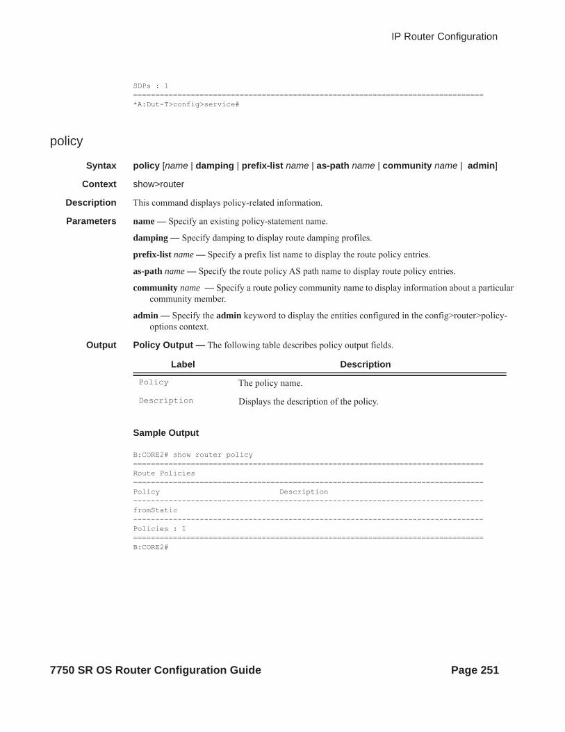
IP Router Configuration
SDPs : 1===============================================================================*A:Dut-T>config>service#
policy
Syntax policy [name | damping | prefix-list name | as-path name | community name | admin]
Context show>router
Description This command displays policy-related information.
Parameters name — Specify an existing policy-statement name.
damping — Specify damping to display route damping profiles.
prefix-list name — Specify a prefix list name to display the route policy entries.
as-path name — Specify the route policy AS path name to display route policy entries.
community name — Specify a route policy community name to display information about a particular community member.
admin — Specify the admin keyword to display the entities configured in the config>router>policy-options context.
Output Policy Output — The following table describes policy output fields.
Sample Output
B:CORE2# show router policy ===============================================================================Route Policies===============================================================================Policy Description -------------------------------------------------------------------------------fromStatic -------------------------------------------------------------------------------Policies : 1===============================================================================B:CORE2#
Label Description
Policy The policy name.
Description Displays the description of the policy.
7750 SR OS Router Configuration Guide Page 251

Show Commands
policy-edits
Syntax policy-edits
Context show>router
Description This command displays edited policy information.
route-table
Syntax route-table [family] [ip-prefix[/prefix-length] [longer|exact|protocol protocol-name] [all]] [next-hop-type type][qos][alternative]route-table [family] summaryroute-table tunnel-endpoints [ip-prefix[/prefix-length]] [longer|exact] [detail]
Context show>router
Description This command displays the active routes in the routing table.
If no command line arguments are specified, all routes are displayed, sorted by prefix.
Parameters family — Specify the type of routing information to be distributed by this peer group.
Values ipv4 — Displays only those BGP peers that have the IPv4 family enabled and not those capable of exchanging IP-VPN routes.ipv6 — Displays the BGP peers that are IPv6 capable.mcast-ipv4 — Displays the BGP peers that are IPv4 multicast capable.
mcast-ipv6 — Displays multicast IPv6 route table.
ip-prefix[/prefix-length] — Displays routes only matching the specified ip-address and length.
Values ipv4-prefix: a.b.c.d (host bits must be set to 0)ipv4-prefix-length: 0 — 32ipv6 ipv6-prefix[/pref*: x:x:x:x:x:x:x:x (eight 16-bit pieces)
x:x:x:x:x:x:d.d.d.dx: [0 — FFFF]Hd: [0 — 255]D
prefix-length: 1 — 128ipv6
longer — Displays routes matching the ip-prefix/mask and routes with longer masks.
exact — Displays the exact route matching the ip-prefix/mask masks.
protocol protocol-name — Displays routes learned from the specified protocol.
Values local, sub-mgmt, managed, static, ospf, ospf3, isis, rip, aggregate, bgp, bgp-vpn
summary — Displays a route table summary information.
tunnel-endpoints — Specifies to include tunnel endpoint information.
Page 252 7750 SR OS Router Configuration Guide
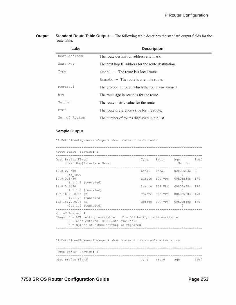
IP Router Configuration
Output Standard Route Table Output — The following table describes the standard output fields for the route table.
Sample Output
*A:Dut-B#config>service>vprn# show router 1 route-table
===============================================================================Route Table (Service: 1)===============================================================================Dest Prefix[Flags] Type Proto Age Pref Next Hop[Interface Name] Metric -------------------------------------------------------------------------------10.0.0.0/30 Local Local 02h09m23s 0 to_4007 010.0.0.8/30 Remote BGP VPN 00h06m38s 170 1.1.1.9 (tunneled) 011.0.0.8/30 Remote BGP VPN 00h06m38s 170 1.1.1.9 (tunneled) 0192.168.0.0/16 [E] Remote BGP VPN 00h06m38s 170 1.1.1.9 (tunneled) 0192.168.0.0/16 [E] Remote BGP VPN 00h06m38s 170 2.1.1.9 (tunneled) 0-------------------------------------------------------------------------------No. of Routes: 4Flags: L = LFA nexthop available B = BGP backup route available E = best-external BGP route available n = Number of times nexthop is repeated===============================================================================
*A:Dut-B#config>service>vprn# show router 1 route-table alternative
===============================================================================Route Table (Service: 1)===============================================================================Dest Prefix[Flags] Type Proto Age Pref
Label Description
Dest Address The route destination address and mask.
Next Hop The next hop IP address for the route destination.
Type Local — The route is a local route.
Remote — The route is a remote route.
Protocol The protocol through which the route was learned.
Age The route age in seconds for the route.
Metric The route metric value for the route.
Pref The route preference value for the route.
No. of Routes The number of routes displayed in the list.
7750 SR OS Router Configuration Guide Page 253

Show Commands
Next Hop[Interface Name] Metric Alt-NextHop Alt- Metric -------------------------------------------------------------------------------10.0.0.0/30 Local Local 02h17m23s 0 to_4007 010.0.0.8/30 Remote BGP VPN 00h14m37s 170 1.1.1.9 (tunneled) 011.0.0.8/30 Remote BGP VPN 00h14m37s 170 1.1.1.9 (tunneled) 0192.168.0.0/16 Remote BGP VPN 00h14m37s 170 1.1.1.9 (tunneled) 0192.168.0.0/16 (Backup) Remote BGP VPN 00h14m37s 170 2.1.1.9 (tunneled) 0192.168.0.0/16 (Best-ext) Remote BGP 00h24m37s 170 10.0.0.9 0-------------------------------------------------------------------------------No. of Routes: 5Flags: Backup = BGP backup route LFA = Loop-Free Alternate nexthop Best-ext = best-external BGP route n = Number of times nexthop is repeated===============================================================================
*A:Dut-B# show router route-table ============================================================================Route Table (Router: Base)============================================================================Dest Prefix[Flags] Type Proto Age PrefNext Hop[Interface Name] Metric----------------------------------------------------------------------------10.10.1.0/24 Local Local 00h01m25s 0ip-10.10.1.2 010.10.2.0/24 [L] Remote ISIS 00h00m58s 1510.10.12.3 1310.10.3.0/24 Local Local 00h01m25s 0ip-10.10.3.2 010.10.4.0/24 Local Local 00h01m25s 0ip-10.10.4.2 010.10.5.0/24 [L] Remote ISIS 00h00m58s 1510.10.12.3 1310.10.6.0/24 [L] Remote ISIS 00h00m58s 1510.10.4.4 2010.10.9.0/24 [L] Remote ISIS 00h00m58s 1510.10.4.4 2010.10.10.0/24 [L] Remote ISIS 00h00m58s 1510.10.12.3 2310.10.11.0/24 [L] Remote ISIS 00h00m58s 1510.10.12.3 1310.10.12.0/24 Local Local 00h01m25s 0ip-10.10.12.2 010.20.1.1/32 [L] Remote ISIS 00h00m58s 1510.10.1.1 1010.20.1.2/32 Local Local 00h01m25s 0system 010.20.1.3/32 [L] Remote ISIS 00h00m58s 1510.10.12.3 310.20.1.4/32 [L] Remote ISIS 00h00m58s 1510.10.4.4 1010.20.1.5/32 [L] Remote ISIS 00h00m58s 15
Page 254 7750 SR OS Router Configuration Guide

IP Router Configuration
10.10.12.3 1310.20.1.6/32 [L] Remote ISIS 00h00m58s 1510.10.4.4 20----------------------------------------------------------------------------No. of Routes: 16Flags: L = LFA nexthop available B = BGP backup route available============================================================================
*A:Dut-B# show router route-table alternative ============================================================================Route Table (Router: Base)============================================================================Dest Prefix[Flags] Type Proto Age PrefNext Hop[Interface Name] MetricAlt-NextHop Alt-Metric----------------------------------------------------------------------------10.10.1.0/24 Local Local 00h02m28s 0ip-10.10.1.2 010.10.2.0/24 Remote ISIS 00h02m01s 1510.10.12.3 1310.10.1.1 (LFA) 2010.10.3.0/24 Local Local 00h02m27s 0ip-10.10.3.2 010.10.4.0/24 Local Local 00h02m28s 0ip-10.10.4.2 010.10.5.0/24 Remote ISIS 00h02m01s 1510.10.12.3 1310.10.1.1 (LFA) 2010.10.6.0/24 Remote ISIS 00h02m01s 1510.10.4.4 2010.10.12.3 (LFA) 1310.10.9.0/24 Remote ISIS 00h02m01s 1510.10.4.4 2010.10.12.3 (LFA) 1310.10.10.0/24 Remote ISIS 00h02m01s 1510.10.12.3 2310.10.4.4 (LFA) 2010.10.11.0/24 Remote ISIS 00h02m01s 1510.10.12.3 1310.10.1.1 (LFA) 2010.10.12.0/24 Local Local 00h02m28s 0ip-10.10.12.2 010.20.1.1/32 Remote ISIS 00h02m01s 1510.10.1.1 1010.10.12.3 (LFA) 1310.20.1.2/32 Local Local 00h02m28s 0system 010.20.1.3/32 Remote ISIS 00h02m05s 1510.10.12.3 310.10.1.1 (LFA) 2010.20.1.4/32 Remote ISIS 00h02m05s 1510.10.4.4 1010.10.12.3 (LFA) 1310.20.1.5/32 Remote ISIS 00h02m05s 1510.10.12.3 1310.10.4.4 (LFA) 2010.20.1.6/32 Remote ISIS 00h02m05s 1510.10.4.4 2010.10.12.3 (LFA) 23
7750 SR OS Router Configuration Guide Page 255

Show Commands
----------------------------------------------------------------------------No. of Routes: 16Flags: Backup = BGP backup routeLFA = Loop-Free Alternate nexthop ============================================================================
*A:Dut-C# show router route-table 1.1.1.1/32
===============================================================================Route Table (Router: Base)===============================================================================Dest Prefix Type Proto Age Pref Next Hop[Interface Name] Metric-------------------------------------------------------------------------------1.1.1.1/32 Remote BGP 00h00m09s 170 10.20.1.1 (tunneled:RSVP:1) 0-------------------------------------------------------------------------------No. of Routes: 1===============================================================================
A:ALA# show router route-table===============================================================================Route Table (Router: Base)===============================================================================Dest Prefix Type Proto Age Pref Next Hop[Interface Name] Metric-------------------------------------------------------------------------------11.2.103.0/24 Remote OSPF 00h59m02s 10 21.2.4.2 211.2.103.0/24 Remote OSPF 00h59m02s 10 22.2.4.2 211.2.103.0/24 Remote OSPF 00h59m02s 10 23.2.4.2 211.2.103.0/24 Remote OSPF 00h59m02s 10 24.2.4.2 211.2.103.0/24 Remote OSPF 00h59m02s 10 100.0.0.1 211.2.103.0/24 Remote OSPF 00h59m02s 10 100.128.0.1 211.4.101.0/24 Local Local 02h14m29s 0...-------------------------------------------------------------------------------A:ALA#
B:ALA-B# show router route-table 100.10.0.0 exact =============================================================================== Route Table (Router: Base) =============================================================================== Dest Address Next Hop Type Proto Age Metric Pref -------------------------------------------------------------------------------
Page 256 7750 SR OS Router Configuration Guide

IP Router Configuration
100.10.0.0/16 Black Hole Remote Static 00h03m17s 1 5 ------------------------------------------------------------------------------- No. of Routes: 1 =============================================================================== B:ALA-B#
A:ALA-A# show router route-table 10.10.0.4===============================================================================Route Table ===============================================================================Dest Address Next Hop Type Protocol Age Metric Pref -------------------------------------------------------------------------------10.10.0.4/32 10.10.34.4 Remote OSPF 3523 1001 10 -------------------------------------------------------------------------------A:ALA-A#
A:ALA-A# show router route-table 10.10.0.4/32 longer===============================================================================Route Table ===============================================================================Dest Address Next Hop Type Protocol Age Metric Pref -------------------------------------------------------------------------------10.10.0.4/32 10.10.34.4 Remote OSPF 3523 1001 10 -------------------------------------------------------------------------------No. of Routes: 1===============================================================================+ : indicates that the route matches on a longer prefixA:ALA-A#
*A:Dut-C# show router route-table
===============================================================================Route Table (Router: Base)===============================================================================Dest Prefix[Flags] Type Proto Age Pref Next Hop[Interface Name] Metric -------------------------------------------------------------------------------1.1.2.0/24 Remote ISIS 00h44m24s 15 1.1.3.1 201.1.2.0/24 Remote ISIS 00h44m24s 15 1.2.3.2 201.1.3.0/24 Local Local 00h44m30s 0 to_Dut-A 01.1.9.0/24 Remote ISIS 00h44m16s 15 1.1.3.1 201.2.3.0/24 Local Local 00h44m30s 0 to_Dut-B 01.2.9.0/24 Remote ISIS 00h43m55s 160 1.2.3.2 1010.12.0.0/24 Local Local 00h44m29s 0 itfToArborCP_02 010.20.1.1/32 Remote ISIS 00h44m24s 15 1.1.3.1 1010.20.1.2/32 Remote ISIS 00h44m28s 15 1.2.3.2 1010.20.1.3/32 Local Local 00h44m32s 0 system 0
7750 SR OS Router Configuration Guide Page 257

Show Commands
20.12.0.43/32 Remote Static 00h44m31s 5 vprn1:mda-1-1 120.12.0.44/32 Remote Static 00h44m31s 5 vprn1:mda-2-1 120.12.0.45/32 Remote Static 00h44m31s 5 vprn1:mda-2-2 120.12.0.46/32 Remote Static 00h44m30s 5 vprn1:mda-3-1 1100.0.0.1/32 Remote TMS 00h34m39s 167 vprn1:mda-1-1 0100.0.0.1/32 Remote TMS 00h34m39s 167 vprn1:mda-3-1 0138.203.71.202/32 Remote Static 00h44m29s 5 10.12.0.2 1-------------------------------------------------------------------------------No. of Routes: 17Flags: L = LFA nexthop available B = BGP backup route available n = Number of times nexthop is repeated===============================================================================A:ALA-A# show router route-table protocol ospf===============================================================================Route Table ===============================================================================Dest Address Next Hop Type Protocol Age Metric Pref -------------------------------------------------------------------------------10.10.0.1/32 10.10.13.1 Remote OSPF 65844 1001 10 10.10.0.2/32 10.10.13.1 Remote OSPF 65844 2001 10 10.10.0.4/32 10.10.34.4 Remote OSPF 3523 1001 10 10.10.0.5/32 10.10.35.5 Remote OSPF 1084022 1001 10 10.10.12.0/24 10.10.13.1 Remote OSPF 65844 2000 10 10.10.15.0/24 10.10.13.1 Remote OSPF 58836 2000 10 10.10.24.0/24 10.10.34.4 Remote OSPF 3523 2000 10 10.10.25.0/24 10.10.35.5 Remote OSPF 399059 2000 10 10.10.45.0/24 10.10.34.4 Remote OSPF 3523 2000 10 -------------------------------------------------------------------------------A:ALA-A#
show router route-table 131.132.133.134/32 next-hop-type tunneled Route Table (Router: Base)========================================================================Dest Prefix Type Proto Age Pref Next Hop[Interface Name] Metric------------------------------------------------------------------------131.132.133.134/32 Remote OSPF 00h02m09s 10 66.66.66.66 10 Next-hop type: tunneled, Owner: RSVP, Tunnel-ID: <out-ifindex-from-route>------------------------------------------------------------------------No. of Routes: 1======================================================================== *A:Dut-B# show router route-table next-hop-type tunneled
===============================================================================Route Table (Router: Base)===============================================================================Dest Prefix Type Proto Age Pref Next Hop[Interface Name] Metric -------------------------------------------------------------------------------10.10.5.0/24 Remote OSPF 00h02m20s 10
Page 258 7750 SR OS Router Configuration Guide

IP Router Configuration
10.20.1.5 (tunneled:RSVP:1) 110010.10.10.0/24 Remote OSPF 00h02m20s 10 10.20.1.5 (tunneled:RSVP:1) 110010.20.1.5/32 Remote OSPF 00h02m20s 10 10.20.1.5 (tunneled:RSVP:1) 10010.20.1.6/32 Remote OSPF 00h02m20s 10 10.20.1.5 (tunneled:RSVP:1) 1100-------------------------------------------------------------------------------No. of Routes: 4===============================================================================
*A:Dut-B# show router route-table 10.20.1.5/32 next-hop-type tunneled
===============================================================================Route Table (Router: Base)===============================================================================Dest Prefix Type Proto Age Pref Next Hop[Interface Name] Metric -------------------------------------------------------------------------------10.20.1.5/32 Remote OSPF 00h03m55s 10 10.20.1.5 (tunneled:RSVP:1) 100-------------------------------------------------------------------------------No. of Routes: 1===============================================================================*A:Dut-C# show router route-table protocol tms
===============================================================================Route Table (Router: Base)===============================================================================Dest Prefix[Flags] Type Proto Age Pref Next Hop[Interface Name] Metric -------------------------------------------------------------------------------100.0.0.1/32 Remote TMS 00h23m07s 167 vprn1:mda-2-1 0-------------------------------------------------------------------------------No. of Routes: 1Flags: L = LFA nexthop available B = BGP backup route available n = Number of times nexthop is repeated===============================================================================*A:Dut-C# *A:Dut-C# show router route-table summary
===============================================================================Route Table Summary (Router: Base)=============================================================================== Active Available------------------------------------------------------------------------------- Static 5 5 Direct 12 12 Host 0 11 BGP 0 0 BGP (Backup) 0 0 VPN Leak 0 0 OSPF 0 0 ISIS 6 6 ISIS (LFA) 0 0 RIP 0 0 LDP 0 0
7750 SR OS Router Configuration Guide Page 259
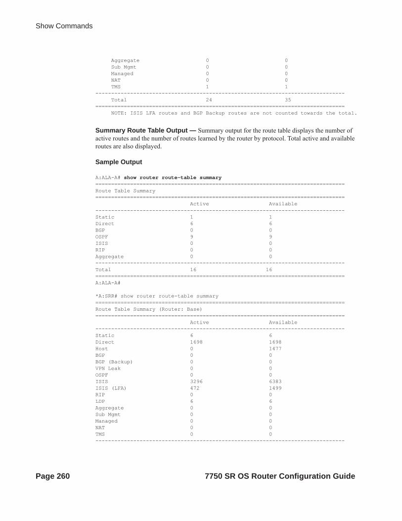
Show Commands
Aggregate 0 0 Sub Mgmt 0 0 Managed 0 0 NAT 0 0 TMS 1 1------------------------------------------------------------------------------- Total 24 35=============================================================================== NOTE: ISIS LFA routes and BGP Backup routes are not counted towards the total.
Summary Route Table Output — Summary output for the route table displays the number of active routes and the number of routes learned by the router by protocol. Total active and available routes are also displayed.
Sample Output
A:ALA-A# show router route-table summary===============================================================================Route Table Summary =============================================================================== Active Available -------------------------------------------------------------------------------Static 1 1 Direct 6 6 BGP 0 0 OSPF 9 9 ISIS 0 0 RIP 0 0 Aggregate 0 0 -------------------------------------------------------------------------------Total 16 16 ===============================================================================A:ALA-A#
*A:SRR# show router route-table summary ===============================================================================Route Table Summary (Router: Base)=============================================================================== Active Available-------------------------------------------------------------------------------Static 6 6Direct 1698 1698Host 0 1477BGP 0 0BGP (Backup) 0 0VPN Leak 0 0OSPF 0 0ISIS 3296 6383ISIS (LFA) 472 1499RIP 0 0LDP 6 6Aggregate 0 0Sub Mgmt 0 0Managed 0 0NAT 0 0TMS 0 0-------------------------------------------------------------------------------
Page 260 7750 SR OS Router Configuration Guide

IP Router Configuration
Total 5006 9570===============================================================================NOTE: ISIS LFA routes and BGP Backup routes are not counted towards the total.*A:SRR#
rtr-advertisement
Syntax rtr-advertisement [interface interface-name] [prefix ipv6-prefix[/prefix-length]]rtr-advertisement [conflicts]
Context show>router
Description This command displays router advertisement information.
If no command line arguments are specified, all routes are displayed, sorted by prefix.
Parameters interface-name — Maximum 32 characters.
ipv6-prefix[/prefix-length] — Displays routes only matching the specified ip-address and length.
Values ipv6 ipv6-prefix[/pref*: x:x:x:x:x:x:x:x (eight 16-bit pieces)x:x:x:x:x:x:d.d.d.dx: [0 — FFFF]Hd: [0 — 255]D
prefix-length: 1 — 128
Output Router-Advertisement Table Output — The following table describes the output fields for router- advertisement.
Label Description
Rtr Advertisement Tx/Last Sent
The number of router advertisements sent and time since they were sent.
Nbr Solicitation Tx
The number of neighbor solicitations sent and time since they were sent.
Nbr Advertisement Tx
The number of neighbor advertisements sent and time since they were sent.
Rtr Advertisement Rx
The number of router advertisements received and time since they were received.
Nbr Advertisement Rx
The number of neighbor advertisements received and time since they were received.
Max Advert Inter-val
The maximum interval between sending router advertisement mes-sages.
Managed Config True — Indicates that DHCPv6 has been configured.
7750 SR OS Router Configuration Guide Page 261

Show Commands
Sample Output
A:Dut-A# show router rtr-advertisement =======================================================================Router Advertisement=======================================================================-------------------------------------------------------------------------------Interface: interfaceNetworkNonDefault-------------------------------------------------------------------------------Rtr Advertisement Tx : 8 Last Sent : 00h01m28s Nbr Solicitation Tx : 83 Last Sent : 00h00m17s Nbr Advertisement Tx : 74 Last Sent : 00h00m25s Rtr Advertisement Rx : 8 Rtr Solicitation Rx : 0 Nbr Advertisement Rx : 83 Nbr Solicitation Rx : 74 -------------------------------------------------------------------------------Max Advert Interval : 601 Min Advert Interval : 201 Managed Config : TRUE Other Config : TRUE Reachable Time : 00h00m00s400ms Router Lifetime : 00h30m01s Retransmit Time : 00h00m00s400ms Hop Limit : 63 Link MTU : 1500 Prefix: 211::/120Autonomous Flag : FALSE On-link flag : FALSE Preferred Lifetime : 07d00h00m Valid Lifetime : 30d00h00m Prefix: 231::/120
False — Indicates that DHCPv6 is not available for address config-uration.
Reachable Time The time, in milliseconds, that a node assumes a neighbor is reachable after receiving a reachability confirmation.
Retransmit Time The time, in milliseconds, between retransmitted neighbor solicitation messages.
Link MTU The MTU number the nodes use for sending packets on the link.
Rtr Solicitation Rx
The number of router solicitations received and time since they were received.
Nbr Solicitation Rx
The number of neighbor solicitations received and time since they were received.
Min Advert Inter-val
The minimum interval between sending ICMPv6 neighbor discovery router advertisement messages.
Other Config True — Indicates there are other stateful configurations.
False — Indicates there are no other stateful configurations.
Router Lifetime Displays the router lifetime in seconds.
Hop Limit Displays the current hop limit.
Label Description (Continued)
Page 262 7750 SR OS Router Configuration Guide

IP Router Configuration
Autonomous Flag : FALSE On-link flag : FALSE Preferred Lifetime : 49710d06h Valid Lifetime : 49710d06h Prefix: 241::/120 Autonomous Flag : TRUE On-link flag : TRUE Preferred Lifetime : 00h00m00s Valid Lifetime : 00h00m00s Prefix: 251::/120Autonomous Flag : TRUE On-link flag : TRUE Preferred Lifetime : 07d00h00m Valid Lifetime : 30d00h00m -------------------------------------------------------------------------------Advertisement from: FE80::200:FF:FE00:2Managed Config : FALSE Other Config : FALSE Reachable Time : 00h00m00s0ms Router Lifetime : 00h30m00s Retransmit Time : 00h00m00s0ms Hop Limit : 64 Link MTU : 0 -------------------------------------------------------------------------------Interface: interfaceServiceNonDefault-------------------------------------------------------------------------------Rtr Advertisement Tx : 8 Last Sent : 00h06m41s Nbr Solicitation Tx : 166 Last Sent : 00h00m04s Nbr Advertisement Tx : 143 Last Sent : 00h00m05s Rtr Advertisement Rx : 8 Rtr Solicitation Rx : 0 Nbr Advertisement Rx : 166 Nbr Solicitation Rx : 143 -------------------------------------------------------------------------------Max Advert Interval : 601 Min Advert Interval : 201 Managed Config : TRUE Other Config : TRUE Reachable Time : 00h00m00s400ms Router Lifetime : 00h30m01s Retransmit Time : 00h00m00s400ms Hop Limit : 63 Link MTU : 1500 Prefix: 23::/120Autonomous Flag : FALSE On-link flag : FALSE Preferred Lifetime : infinite Valid Lifetime : infinite Prefix: 24::/120Autonomous Flag : TRUE On-link flag : TRUE Preferred Lifetime : 00h00m00s Valid Lifetime : 00h00m00s Prefix: 25::/120Autonomous Flag : TRUE On-link flag : TRUE Preferred Lifetime : 07d00h00m Valid Lifetime : 30d00h00m -------------------------------------------------------------------------------Advertisement from: FE80::200:FF:FE00:2Managed Config : FALSE Other Config : FALSE Reachable Time : 00h00m00s0ms Router Lifetime : 00h30m00s Retransmit Time : 00h00m00s0ms Hop Limit : 64 Link MTU : 0 Prefix: 2::/120Autonomous Flag : TRUE On-link flag : TRUE Preferred Lifetime : 07d00h00m Valid Lifetime : 30d00h00m Prefix: 23::/120Autonomous Flag : TRUE On-link flag : TRUE Preferred Lifetime : 07d00h00m Valid Lifetime : 30d00h00m Prefix: 24::/119Autonomous Flag : TRUE On-link flag : TRUE
7750 SR OS Router Configuration Guide Page 263

Show Commands
Preferred Lifetime : 07d00h00m Valid Lifetime : 30d00h00m Prefix: 25::/120Autonomous Flag : TRUE On-link flag : TRUE Preferred Lifetime : 07d00h00m Valid Lifetime : infinite Prefix: 231::/120Autonomous Flag : TRUE On-link flag : TRUE Preferred Lifetime : 07d00h00m Valid Lifetime : 30d00h00m -------------------------------------------------------------------------------...A:Dut-A#
Output Router-Advertisement Conflicts Output — The following table describes the output fields for router- advertisement conflicts.
Sample Output
A:Dut-A# show>router# rtr-advertisement conflicts ===============================================================================Router Advertisement===============================================================================Interface: interfaceNetworkNonDefault-------------------------------------------------------------------------------Advertisement from: FE80::200:FF:FE00:2Managed Config : FALSE [TRUE]Other Config : FALSE [TRUE]Reachable Time : 00h00m00s0ms [00h00m00s400ms]Router Lifetime : 00h30m00s [00h30m01s]Retransmit Time : 00h00m00s0ms [00h00m00s400ms]Hop Limit : 64 [63]Link MTU : 0 [1500] Prefix not present in neighbor router advertisementPrefix: 211::/120Autonomous Flag : FALSE On-link flag : FALSE Preferred Lifetime : 07d00h00m Valid Lifetime : 30d00h00m Prefix not present in neighbor router advertisement
Label Description
Advertisement from
The address of the advertising router.
Reachable Time The time, in milliseconds, that a node assumes a neighbor is reachable after receiving a reachability confirmation.
Router Lifetime Displays the router lifetime in seconds.
Retransmit Time The time, in milliseconds, between retransmitted neighbor solicitation messages.
Hop Limit Displays the current hop limit
Link MTU The MTU number the nodes use for sending packets on the link.
Page 264 7750 SR OS Router Configuration Guide
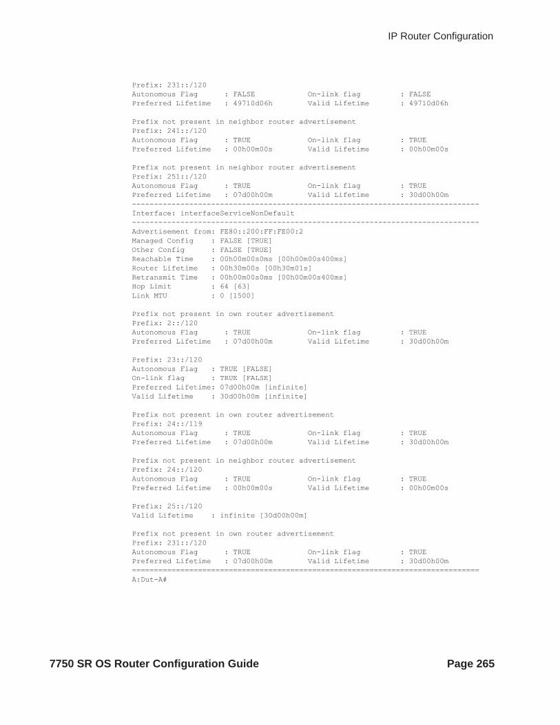
IP Router Configuration
Prefix: 231::/120Autonomous Flag : FALSE On-link flag : FALSE Preferred Lifetime : 49710d06h Valid Lifetime : 49710d06h Prefix not present in neighbor router advertisementPrefix: 241::/120Autonomous Flag : TRUE On-link flag : TRUE Preferred Lifetime : 00h00m00s Valid Lifetime : 00h00m00s Prefix not present in neighbor router advertisementPrefix: 251::/120Autonomous Flag : TRUE On-link flag : TRUE Preferred Lifetime : 07d00h00m Valid Lifetime : 30d00h00m -------------------------------------------------------------------------------Interface: interfaceServiceNonDefault-------------------------------------------------------------------------------Advertisement from: FE80::200:FF:FE00:2Managed Config : FALSE [TRUE]Other Config : FALSE [TRUE]Reachable Time : 00h00m00s0ms [00h00m00s400ms]Router Lifetime : 00h30m00s [00h30m01s]Retransmit Time : 00h00m00s0ms [00h00m00s400ms]Hop Limit : 64 [63]Link MTU : 0 [1500] Prefix not present in own router advertisementPrefix: 2::/120Autonomous Flag : TRUE On-link flag : TRUE Preferred Lifetime : 07d00h00m Valid Lifetime : 30d00h00m Prefix: 23::/120Autonomous Flag : TRUE [FALSE]On-link flag : TRUE [FALSE]Preferred Lifetime: 07d00h00m [infinite]Valid Lifetime : 30d00h00m [infinite] Prefix not present in own router advertisementPrefix: 24::/119Autonomous Flag : TRUE On-link flag : TRUE Preferred Lifetime : 07d00h00m Valid Lifetime : 30d00h00m Prefix not present in neighbor router advertisementPrefix: 24::/120Autonomous Flag : TRUE On-link flag : TRUE Preferred Lifetime : 00h00m00s Valid Lifetime : 00h00m00s Prefix: 25::/120Valid Lifetime : infinite [30d00h00m] Prefix not present in own router advertisementPrefix: 231::/120Autonomous Flag : TRUE On-link flag : TRUE Preferred Lifetime : 07d00h00m Valid Lifetime : 30d00h00m ===============================================================================A:Dut-A#
7750 SR OS Router Configuration Guide Page 265

Show Commands
static-arp
Syntax static-arp [ip-addr | ip-int-name | mac ieee-mac-addr]
Context show>router
Description This command displays the router static ARP table sorted by IP address. If no options are present, all ARP entries are displayed.
Parameters ip-addr — Only displays static ARP entries associated with the specified IP address.
ip-int-name — Only displays static ARP entries associated with the specified IP interface name.
mac ieee-mac-addr — Only displays static ARP entries associated with the specified MAC address.
Output Static ARP Table Output — The following table describes the output fields for the ARP table.
Sample Output
A:ALA-A# show router static-arp===============================================================================ARP Table ===============================================================================IP Address MAC Address Age Type Interface -------------------------------------------------------------------------------10.200.0.253 00:00:5a:40:00:01 00:00:00 Sta to-ser1 12.200.1.1 00:00:5a:01:00:33 00:00:00 Inv to-ser1a-------------------------------------------------------------------------------No. of ARP Entries: 1 ===============================================================================A:ALA-A#
A:ALA-A# show router static-arp 12.200.1.1===============================================================================ARP Table ===============================================================================IP Address MAC Address Age Type Interface -------------------------------------------------------------------------------
Label Description
IP Address The IP address of the static ARP entry.
MAC Address The MAC address of the static ARP entry.
Age The age of the ARP entry. Static ARPs always have 00:00:00 for the age.
Type Inv — The ARP entry is an inactive static ARP entry (invalid).
Sta — The ARP entry is an active static ARP entry.
Interface The IP interface name associated with the ARP entry.
No. of ARP Entries
The number of ARP entries displayed in the list.
Page 266 7750 SR OS Router Configuration Guide

IP Router Configuration
12.200.1.1 00:00:5a:01:00:33 00:00:00 Inv to-ser1 ===============================================================================A:ALA-A#
A:ALA-A# show router static-arp to-ser1===============================================================================ARP Table ===============================================================================IP Address MAC Address Age Type Interface -------------------------------------------------------------------------------10.200.0.253 00:00:5a:40:00:01 00:00:00 Sta to-ser1 ===============================================================================A:ALA-A#
A:ALA-A# show router static-arp mac 00:00:5a:40:00:01===============================================================================ARP Table ===============================================================================IP Address MAC Address Age Type Interface -------------------------------------------------------------------------------10.200.0.253 00:00:5a:40:00:01 00:00:00 Sta to-ser1 ===============================================================================A:ALA-A#
static-route
Syntax static-route [family] [[ip-prefix /mask] | [preference preference] | [next-hop ip-address] | tag tag]
Context show>router
Description This command displays the static entries in the routing table. If no options are present, all static routes are displayed sorted by prefix.
Parameters family — Specify the type of routing information to be distributed by this peer group.
Values ipv4 — Displays only those BGP peers that have the IPv4 family enabled and not those capable of exchanging IP-VPN routes.ipv6 — Displays the BGP peers that are IPv6 capable.mcast-ipv4 — Displays the BGP peers that are IPv4 multicast capable.
ip-prefix /mask — Displays static routes only matching the specified ip-prefix and mask.
Values ipv4-prefix: a.b.c.d (host bits must be 0)ipv4-prefix-length: 0 — 32ipv6-prefix: x:x:x:x:x:x:x:x (eight 16-bit pieces)
x:x:x:x:x:x:d.d.d.dx: [0 — FFFF]Hd: [0 — 255]D
ipv6-prefix-length: 0 — 128
7750 SR OS Router Configuration Guide Page 267

Show Commands
preference preference — Only displays static routes with the specified route preference.
Values 0 — 65535
next-hop ip-address — Only displays static routes with the specified next hop IP address.
Values ipv4-address: a.b.c.d (host bits must be 0)ipv6-address: x:x:x:x:x:x:x:x (eight 16-bit pieces)
x:x:x:x:x:x:d.d.d.dx: [0 — FFFF]Hd: [0 — 255]D
tag tag — Displays the tag used to add a 32-bit integer tag to the static route. The tag is used in route policies to control distribution of the route into other protocols.
Values 1 — 4294967295
Output Static Route Output — The following table describes the output fields for the static route table.
Sample Output
A:ALA-A# show router static-route===============================================================================
Label Description
IP Addr/mask The static route destination address and mask.
Pref The route preference value for the static route.
Metric The route metric value for the static route.
Type BH — The static route is a black hole route. The Nexthop for this type of route is black-hole.
ID — The static route is an indirect route, where the nexthop for this type of route is the non-directly connected next hop.
NH — The route is a static route with a directly connected next hop. The Nexthop for this type of route is either the next hop IP address or an egress IP interface name.
Next Hop The next hop for the static route destination.
Protocol The protocol through which the route was learned.
Interface The egress IP interface name for the static route.n/a — indicates there is no current egress interface because the static route is inactive or a black hole route.
Active N — The static route is inactive; for example, the static route is disabled or the next hop IP interface is down.
Y — The static route is active.
No. of Routes The number of routes displayed in the list.
Page 268 7750 SR OS Router Configuration Guide

IP Router Configuration
Route Table =============================================================================== IP Addr/mask Pref Metric Type Nexthop Interface Active ------------------------------------------------------------------------------- 192.168.250.0/24 5 1 ID 10.200.10.1 to-ser1 Y 192.168.252.0/24 5 1 NH 10.10.0.254 n/a N 192.168.253.0/24 5 1 NH to-ser1 n/a N 192.168.253.0/24 5 1 NH 10.10.0.254 n/a N 192.168.254.0/24 4 1 BH black-hole n/a Y =============================================================================== A:ALA-A#
A:ALA-A# show router static-route 192.168.250.0/24=============================================================================== Route Table =============================================================================== IP Addr/mask Pref Metric Type Nexthop Interface Active ------------------------------------------------------------------------------- 192.168.250.0/24 5 1 ID 10.200.10.1 to-ser1 Y =============================================================================== A:ALA-A#
A:ALA-A# show router static-route preference 4=============================================================================== Route Table =============================================================================== IP Addr/mask Pref Metric Type Nexthop Interface Active ------------------------------------------------------------------------------- 192.168.254.0/24 4 1 BH black-hole n/a Y =============================================================================== A:ALA-A#
A:ALA-A# show router static-route next-hop 10.10.0.254=============================================================================== Route Table =============================================================================== IP Addr/mask Pref Metric Type Nexthop Interface Active ------------------------------------------------------------------------------- 192.168.253.0/24 5 1 NH 10.10.0.254 n/a N =============================================================================== A:ALA-A# *A:sim1# show router static-route 10.10.0.0/16 detail=============================================================================== Static Route Table (Router: Base) Family : [IPv4|MCast-IPv4|IPv6]=============================================================================== Network : 3FFD:FFFF:FFFF:FFFF:FFFF:FFFF:FFFF:FFE3/120 Type : [Nexthop|Indirect|Black-hole]Nexthop : [address | LSP label & name] Nexthop type: [IP|LDP|RSVP-TE] Interface :Metric : 1 Prefence : 5Active : [Y|N] Admin State : [Up|Down]Tag : BFD: [enable|disabled]
CPE-check: [enabled|disabled] State: [Up|Down] Target : <address>
7750 SR OS Router Configuration Guide Page 269

Show Commands
Interval : [value | n/a] Drop Count : <value>Log : [Y|N]CPE Host Up/Dn Time : 0d 16:32:28CPE Echo Req Tx : 0 CPE Echo Reply Rx: 0CPE Up Transitions : 0 CPE Down Transitions : 0CPE TTL : 13=============================================================================== A:sim1#
*A:CPM133>config>router# show router static-route 3.3.3.3/32 detail
===============================================================================Static Route Table (Router: Base) Family: IPv4===============================================================================Prefix : 3.3.3.3/32Nexthop : n/aType : Blackhole Nexthop Type : IPInterface : n/a Active : YPrefix List : n/a Prefix List Type : n/aMetric : 1 Preference : 5Admin State : Up Tag : 0BFD : disabled Community : 100:33CPE-check : disabled-------------------------------------------------------------------------------No. of Static Routes: 1
===============================================================================
service-prefix
Syntax service-prefix
Description This command displays the address ranges reserved by this node for services sorted by prefix.
Output Service Prefix Output — The following table describes the output fields for service prefix information.
Sample Output
A:ALA-A# show router service-prefix=================================================
Label Description
IP Prefix The IP prefix of the range of addresses included in the range for services.
Mask The subnet mask length associated with the IP prefix.
Exclusive false — Addresses in the range are not exclusively for use for service IP addresses.true — Addresses in the range are exclusively for use for service IP addresses and cannot be assigned to network IP interfaces.
Page 270 7750 SR OS Router Configuration Guide

IP Router Configuration
Address Ranges reserved for Services =================================================IP Prefix Mask Exclusive -------------------------------------------------172.16.1.0 24 true 172.16.2.0 24 false =================================================A:ALA-A#
sgt-qos
Syntax sgt-qos
Context show>router
Description This command displays self-generated traffic QoS related information.
application
Syntax application [app-name] [dscp|dot1p]
Context show>router>sgt-qos
Description This command displays application QoS settings.
Parameters app-name — The specific application.
Values arp, bgp, cflowd, dhcp, dns, ftp, icmp, igmp, isis, ldp, mld, msdp, ndis, ntp, ospf, pimradius, rip, rsvpsnmp, snmp-notification, srrp, ssh, syslog, tacplus, telnet, tftp, traceroute, vrrp, pppoe
dscp-map
Syntax dscp-map [dscp-name]
Context show>router>sgt-qos
Description This command displays DSCP to FC mappings.
Parameters dscp-name — The specific DSCP name.
Values be, ef, cp1, cp2, cp3, cp4, cp5, cp6, cp7, cp9, cs1, cs2, cs3, cs4, cs5, nc1, nc2, af11, af12, af13, af21, af22, af23, af31, af32, af33, af41, af42, af43, cp11, cp13, cp15, cp17, cp19, cp21, cp23, cp25, cp27, cp29, cp31, cp33, cp35, cp37, cp39, cp41, cp42, cp43, cp44, cp45, cp47, cp49, cp50, cp51, cp52, cp53, cp54, cp55, cp57, cp58, cp59, cp60, cp61, cp62, cp63
7750 SR OS Router Configuration Guide Page 271

Show Commands
status
Syntax status
Context show>router
Description This command displays the router status.
Output Router Status Output — The following table describes the output fields for router status information.
Label Description
Router The administrative and operational states for the router.
OSPF The administrative and operational states for the OSPF protocol.
RIP The administrative and operational states for the RIP protocol.
ISIS The administrative and operational states for the IS-IS protocol.
MPLS The administrative and operational states for the MPLS protocol.
RSVP The administrative and operational states for the RSVP protocol.
LDP The administrative and operational states for the LDP protocol.
BGP The administrative and operational states for the BGP protocol.
IGMP The administrative and operational states for the IGMP protocol.
MLD The administrative and operational states for the MLD protocol.
PIM The administrative and operational states for the PIM protocol.
PIMv4 The administrative and operational states for the PIMv4 protocol..
PIMv6 The administrative and operational states for the PIMv6 protocol..
OSPFv3 The administrative and operational states for the OSPFv3 protocol.
MSDP The administrative and operational states for the HSDP protocol
Max Routes The maximum number of routes configured for the system.
Total Routes The total number of routes in the route table.
ECMP Max Routes The number of ECMP routes configured for path sharing.
service-id state — Current single SFM statestart — Last time this vRtr went into overload, after having respected the hold-off timeinterval — How long the vRtr remained or is in overload
Page 272 7750 SR OS Router Configuration Guide

IP Router Configuration
Sample Output
Note that there are multiple instances of OSPF. OSPF-0 is persistent. OSPF-1 through OSPF-31 are present when that particular OSPF instance is configured. *A:Performance# show router status================================================================Router Status (Router: Base)================================================================ Admin State Oper State----------------------------------------------------------------Router Up UpOSPFv2-0 Up UpRIP Up Up
ICMP Tunneling No — ICMP tunneling is disabled.Yes — TICMP tunneling is enabled.
VPRN Local TTL Propagate
inherit — VPRN instance is to inherit the global configurationnone — TTL of IP packet is not propagated into the VC or transport label stackvc-only — TTL of the IP packet is propagated into the VC label and not into the labels in the transport label stackal — TTL of the IP packet is propagated into the VC label and all labels in the transport label stack
VPRN Transit TTL Propag*
inherit — VPRN instance is to inherit the global configurationnone — TTL of IP packet is not propagated into the VC or transport label stackvc-only — TTL of the IP packet is propagated into the VC label and not into the labels in the transport label stackal — TTL of the IP packet is propagated into the VC label and all labels in the transport label stack
Label Route Local TTL P*
all — TTL of the IP packet is propagated into all labels of the transport label stacknone — TTL of the IP packet is not propagated into the transport label stack
Label Route Tran-sit TTL*
all — TTL of the IP packet is propagated into all labels of the transport label stacknone — TTL of the IP packet is not propagated into the transport label stack
LSR Label Route TTL Pro*
all — TTL of the swapped label is propagated into all labels of the transport label stacknone — TTL of the swapped label is not propagated into the transport label stack
Triggered Poli-cies
No — Triggered route policy re-evaluation is disabled.Yes — Triggered route policy re-evaluation is enabled.
Label Description (Continued)
7750 SR OS Router Configuration Guide Page 273

Show Commands
ISIS Up UpMPLS Not configured Not configuredRSVP Not configured Not configuredLDP Not configured Not configuredBGP Up UpIGMP Not configured Not configuredPIM Not configured Not configuredOSPFv3 Not configured Not configuredMSDP Not configured Not configuredMax Routes No LimitTotal IPv4 Routes 244285Total IPv6 Routes 0Max Multicast Routes No LimitTotal Multicast Routes PIM not configuredECMP Max Routes 1Triggered Policies No================================================================*A:Performance#
*A:Performance# configure router ospf [1..31] shutdown*A:Performance# show router status================================================================Router Status (Router: Base)================================================================ Admin State Oper State----------------------------------------------------------------Router Up UpOSPFv2-0 Up UpOSPFv2-1 Down DownOSPFv2-2 Down DownOSPFv2-3 Down DownOSPFv2-4 Down DownOSPFv2-5 Down DownOSPFv2-6 Down DownOSPFv2-7 Down DownOSPFv2-8 Down DownOSPFv2-9 Down DownOSPFv2-10 Down DownOSPFv2-11 Down DownOSPFv2-12 Down DownOSPFv2-13 Down DownOSPFv2-14 Down DownOSPFv2-15 Down DownOSPFv2-16 Down DownOSPFv2-17 Down DownOSPFv2-18 Down DownOSPFv2-19 Down DownOSPFv2-20 Down DownOSPFv2-21 Down DownOSPFv2-22 Down DownOSPFv2-23 Down DownOSPFv2-24 Down DownOSPFv2-25 Down DownOSPFv2-26 Down DownOSPFv2-27 Down DownOSPFv2-28 Down DownOSPFv2-29 Down DownOSPFv2-30 Down DownOSPFv2-31 Down Down
Page 274 7750 SR OS Router Configuration Guide

IP Router Configuration
RIP Up UpISIS Up UpMPLS Not configured Not configuredRSVP Not configured Not configuredLDP Not configured Not configuredBGP Up UpIGMP Not configured Not configuredPIM Not configured Not configuredOSPFv3 Not configured Not configuredMSDP Not configured Not configuredMax Routes No LimitTotal IPv4 Routes 244277Total IPv6 Routes 0Max Multicast Routes No LimitTotal Multicast Routes PIM not configuredECMP Max Routes 1Single SFM Overload Enabled hold-off 30 secSingle SFM State normalSingle SFM Start 004 19:03:39.680Single SFM Interval 0d 00:16:06Reassembly ISA-BB group Not configured Ipv6 Nbr Reachab. time Not configured 30Triggered Policies No================================================================*A:Performance#
Sample Output
The folowing show command outputs show TTL propagation and ICMP tunneling configurations, first in base router and then in a VPRN service. *A:Performance# show router status================================================================Router Status (Router: Base)================================================================ Admin State Oper State----------------------------------------------------------------Router Up UpOSPFv2-0 Up UpOSPFv2-2 Down DownRIP Not configured Not configuredRIP-NG Not configured Not configuredISIS-0 Up UpISIS-1024 Down DownMPLS Down DownRSVP Down DownLDP Up DownBGP Up DownIGMP MLD PIM PIMv4 PIMv6 OSPFv3 MSDP
Max IPv4 Routes No Limit
7750 SR OS Router Configuration Guide Page 275

Show Commands
Max IPv6 Routes No LimitTotal IPv4 Routes 0Total IPv6 Routes 0Max Multicast Routes No LimitTotal IPv4 Mcast Routes PIM not configuredTotal IPv6 Mcast Routes PIM not configuredECMP Max Routes 1Mcast Info Policy defaultTriggered Policies NoLDP Shortcut DisabledSingle SFM Overload DisabledIP Fast Reroute DisabledICMP Tunneling DisabledReassembly ISA-BB group Not configuredICMP Tunneling Disabled Ipv6 Nbr Reachab. time Not configured 30IPv6 Nbr stale time (s) 14400VPRN Local TTL Propagate vc-onlyVPRN Transit TTL Propag* vc-onlyLabel Route Local TTL P* noneLabel Route Transit TTL* noneLSR Label Route TTL Pro* none===============================================================================* indicates that the corresponding row element may have been truncated.*B:bkvm31#
The folowing is output of the show command for the TTL propagation and ICMP tunneling configurations in a VPRN service. The ttl-propagation has been specified as local and all for VPRN service 5001.
*A:Dut-A# configure service vprn 5001 ttl-propagate local all *A:Dut-A# show router 5001 status
===============================================================================Router Status (Service: 5001)=============================================================================== Admin State Oper State-------------------------------------------------------------------------------Router Up UpOSPFv2 Not configured Not configuredRIP Not configured Not configuredRIP-NG Not configured Not configuredISIS Not configured Not configuredMPLS Not configured Not configuredRSVP Not configured Not configuredLDP Not configured Not configuredBGP Not configured Not configuredIGMP Not configured Not configuredMLD Not configured Not configuredPIM Not configured Not configuredPIMv4 Not configured Not configuredPIMv6 Not configured Not configuredOSPFv3 Not configured Not configuredMSDP Not configured Not configured
Max IPv4 Routes No Limit Max IPv6 Routes No Limit Total IPv4 Routes 2 Total IPv6 Routes 2
Page 276 7750 SR OS Router Configuration Guide
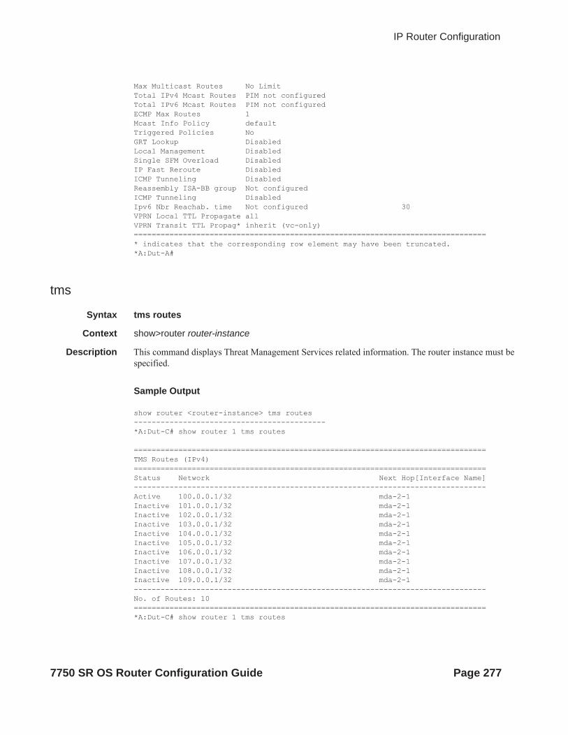
IP Router Configuration
Max Multicast Routes No Limit Total IPv4 Mcast Routes PIM not configured Total IPv6 Mcast Routes PIM not configured ECMP Max Routes 1 Mcast Info Policy default Triggered Policies No GRT Lookup Disabled Local Management Disabled Single SFM Overload Disabled IP Fast Reroute Disabled ICMP Tunneling Disabled Reassembly ISA-BB group Not configured ICMP Tunneling Disabled Ipv6 Nbr Reachab. time Not configured 30VPRN Local TTL Propagate all VPRN Transit TTL Propag* inherit (vc-only) ===============================================================================* indicates that the corresponding row element may have been truncated.*A:Dut-A#
tms
Syntax tms routes
Context show>router router-instance
Description This command displays Threat Management Services related information. The router instance must be specified.
Sample Output
show router <router-instance> tms routes-------------------------------------------*A:Dut-C# show router 1 tms routes
===============================================================================TMS Routes (IPv4)===============================================================================Status Network Next Hop[Interface Name]-------------------------------------------------------------------------------Active 100.0.0.1/32 mda-2-1Inactive 101.0.0.1/32 mda-2-1Inactive 102.0.0.1/32 mda-2-1Inactive 103.0.0.1/32 mda-2-1Inactive 104.0.0.1/32 mda-2-1Inactive 105.0.0.1/32 mda-2-1Inactive 106.0.0.1/32 mda-2-1Inactive 107.0.0.1/32 mda-2-1Inactive 108.0.0.1/32 mda-2-1Inactive 109.0.0.1/32 mda-2-1-------------------------------------------------------------------------------No. of Routes: 10===============================================================================*A:Dut-C# show router 1 tms routes
7750 SR OS Router Configuration Guide Page 277

Show Commands
===============================================================================TMS Routes (IPv4)===============================================================================Status Network Next Hop[Interface Name]-------------------------------------------------------------------------------Active 100.0.0.1/32 mda-2-1-------------------------------------------------------------------------------No. of Routes: 1===============================================================================
tunnel-table
Syntax tunnel-table [ip-address[/mask]] [protocol protocol | sdp sdp-id] [summary]
Context show>router
Description This command displays tunnel table information. Note that auto-bind GRE tunnels are not displayed in show command output. GRE tunnels are not the same as SDP tunnels that use the GRE encapsulation type. When the auto-bind command is used when configuring a VPRN service, it means the MP-BGP NH resolution is refering to the core routing instance for IP reachability. For a VPRN service this object specifies the lookup to be used by the routing instance if no SDP to the destination exists.
Parameters ip-address[/mask] — Displays the specified tunnel table’s destination IP address and mask.
protocol protocol — Dislays LDP protocol information.
sdp sdp-id — Displays information pertaining to the specified SDP.
summary — Displays summary tunnel table information.
Output Tunnel Table Output — The following table describes tunnel table output fields.
Sample Output
*A:Dut-D>config>service>vpls# show router tunnel-table sdp 17407=======================================================================
Label Description
Destination The route’s destination address and mask.
Owner Specifies the tunnel owner.
Encap Specifies the tunnel’s encapsulation type.
Tunnel ID Specifies the tunnel (SDP) identifier.
Pref Specifies the route preference for routes learned from the configured peer(s).
Nexthop The next hop for the route’s destination.
Metric The route metric value for the route.
Page 278 7750 SR OS Router Configuration Guide

IP Router Configuration
Tunnel Table (Router: Base)===============================================================================Destination Owner Encap TunnelId Pref Nexthop Metric-----------------------------------------------------------------------127.0.68.0/32 sdp MPLS 17407 5 127.0.68.0 0=======================================================================*A:Dut-D# show service id 1 sdp 17407:4294967294 detail=======================================================================Service Destination Point (Sdp Id : 17407:4294967294) Details=======================================================================------------------------------------------------------------------------------- Sdp Id 17407:4294967294 -(not applicable)-----------------------------------------------------------------------Description : (Not Specified)SDP Id : 17407:4294967294 Type : VplsPmsiSplit Horiz Grp : (Not Specified)VC Type : Ether VC Tag : n/aAdmin Path MTU : 9194 Oper Path MTU : 9194Delivery : MPLSFar End : not applicableTunnel Far End : n/a LSP Types : NoneHash Label : Disabled Hash Lbl Sig Cap : DisabledOper Hash Label : Disabled Admin State : Up Oper State : UpAcct. Pol : None Collect Stats : DisabledIngress Label : 0 Egress Label : 3Ingr Mac Fltr-Id : n/a Egr Mac Fltr-Id : n/aIngr IP Fltr-Id : n/a Egr IP Fltr-Id : n/aIngr IPv6 Fltr-Id : n/a Egr IPv6 Fltr-Id : n/aAdmin ControlWord : Not Preferred Oper ControlWord : FalseLast Status Change : 12/14/2012 12:42:22 Signaling : NoneLast Mgmt Change : 12/14/2012 12:42:19 Force Vlan-Vc : DisabledEndpoint : N/A Precedence : 4PW Status Sig : EnabledClass Fwding State : DownFlags : NoneTime to RetryReset : never Retries Left : 3Mac Move : Blockable Blockable Level : TertiaryLocal Pw Bits : NonePeer Pw Bits : NonePeer Fault Ip : NonePeer Vccv CV Bits : NonePeer Vccv CC Bits : NoneApplication Profile: NoneMax Nbr of MAC Addr: No Limit Total MAC Addr : 0Learned MAC Addr : 0 Static MAC Addr : 0 MAC Learning : Enabled Discard Unkwn Srce: DisabledMAC Aging : EnabledBPDU Translation : DisabledL2PT Termination : DisabledMAC Pinning : DisabledIgnore Standby Sig : False Block On Mesh Fail: FalseOper Group : (none) Monitor Oper Grp : (none)Rest Prot Src Mac : DisabledAuto Learn Mac Prot: Disabled RestProtSrcMacAct : Disable Ingress Qos Policy : (none) Egress Qos Policy : (none)
7750 SR OS Router Configuration Guide Page 279

Show Commands
Ingress FP QGrp : (none) Egress Port QGrp : (none)Ing FP QGrp Inst : (none) Egr Port QGrp Inst: (none) -----------------------------------------------------------------------ETH-CFM SDP-Bind specifics-----------------------------------------------------------------------V-MEP Filtering : Disabled KeepAlive Information :Admin State : Disabled Oper State : DisabledHello Time : 10 Hello Msg Len : 0Max Drop Count : 3 Hold Down Time : 10 Statistics :I. Fwd. Pkts. : 0 I. Dro. Pkts. : 0I. Fwd. Octs. : 0 I. Dro. Octs. : 0E. Fwd. Pkts. : 2979761 E. Fwd. Octets : 476761760 -----------------------------------------------------------------------Control Channel Status-----------------------------------------------------------------------PW Status : disabled Refresh Timer : <none>Peer Status Expire : false Clear On Timeout : true MCAC Policy Name :MCAC Max Unconst BW: no limit MCAC Max Mand BW : no limitMCAC In use Mand BW: 0 MCAC Avail Mand BW: unlimitedMCAC In use Opnl BW: 0 MCAC Avail Opnl BW: unlimited -----------------------------------------------------------------------RSVP/Static LSPs-----------------------------------------------------------------------Associated LSP List :No LSPs Associated -----------------------------------------------------------------------Class-based forwarding :-----------------------------------------------------------------------Class forwarding : Disabled EnforceDSTELspFc : DisabledDefault LSP : Uknwn Multicast LSP : None =======================================================================FC Mapping Table=======================================================================FC Name LSP Name-----------------------------------------------------------------------No FC Mappings
-----------------------------------------------------------------------Stp Service Destination Point specifics-----------------------------------------------------------------------Stp Admin State : Down Stp Oper State : DownCore Connectivity : DownPort Role : N/A Port State : ForwardingPort Number : 0 Port Priority : 128Port Path Cost : 10 Auto Edge : EnabledAdmin Edge : Disabled Oper Edge : N/ALink Type : Pt-pt BPDU Encap : Dot1d
Page 280 7750 SR OS Router Configuration Guide

IP Router Configuration
Root Guard : Disabled Active Protocol : N/ALast BPDU from : N/ADesignated Bridge : N/A Designated Port Id: N/A Fwd Transitions : 0 Bad BPDUs rcvd : 0Cfg BPDUs rcvd : 0 Cfg BPDUs tx : 0TCN BPDUs rcvd : 0 TCN BPDUs tx : 0TC bit BPDUs rcvd : 0 TC bit BPDUs tx : 0RST BPDUs rcvd : 0 RST BPDUs tx : 0-----------------------------------------------------------------------Number of SDPs : 1-----------------------------------------------------------------------=======================================================================
*A:Dut-C# show router tunnel-table sdp 17407 ========================================================================Tunnel Table (Router: Base)
========================================================================
Destination Owner Encap TunnelId Pref Nexthop Metric
------------------------------------------------------------------------
127.0.68.0/32 sdp MPLS 17407 5 127.0.68.0 0
========================================================================
A:ALA-A>config>service# show router tunnel-table =============================================================================== Tunnel Table ================================================================== DestinationOwnerEncapTunnel IdPrefNexthopMetric ------------------------------------------------------------------------------- 10.0.0.1/32 sdp GRE 10 5 10.0.0.1 0 10.0.0.1/32 sdp GRE 21 5 10.0.0.1 0 10.0.0.1/32 sdp GRE 31 5 10.0.0.1 0 10.0.0.1/32 sdp GRE 41 5 10.0.0.1 0 =============================================================================== A:ALA-A>config>service#
A:ALA-A>config>service# show router tunnel-table summary===============================================================================Tunnel Table Summary (Router: Base)=============================================================================== Active Available-------------------------------------------------------------------------------LDP 1 1SDP 1 1===============================================================================A:ALA-A>config>service#
7750 SR OS Router Configuration Guide Page 281
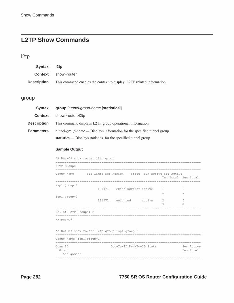
Show Commands
L2TP Show Commands
l2tp
Syntax l2tp
Context show>router
Description This command enables the context to display L2TP related information.
group
Syntax group [tunnel-group-name [statistics]]
Context show>router>l2tp
Description This command displays L2TP group operational information.
Parameters tunnel-group-name — Displays information for the specified tunnel group.
statistics — Displays statistics for the specified tunnel group.
Sample Output
*A:Dut-C# show router l2tp group ===============================================================================L2TP Groups===============================================================================Group Name Ses Limit Ses Assign State Tun Active Ses Active Tun Total Ses Total -------------------------------------------------------------------------------isp1.group-1 131071 existingFirst active 1 1 1 1 isp1.group-2 131071 weighted active 2 5 3 8 -------------------------------------------------------------------------------No. of L2TP Groups: 2===============================================================================*A:Dut-C#
*A:Dut-C# show router l2tp group isp1.group-2 ===============================================================================Group Name: isp1.group-2===============================================================================Conn ID Loc-Tu-ID Rem-Tu-ID State Ses Active Group Ses Total Assignment-------------------------------------------------------------------------------
Page 282 7750 SR OS Router Configuration Guide

IP Router Configuration
143523840 2190 17525 established 2 isp1.group-2 3 isp1.tunnel-3236912640 3615 58919 closedByPeer 0 isp1.group-2 2 isp1.tunnel-2658178048 10043 33762 draining 3 isp1.group-2 3 isp1.tunnel-2-------------------------------------------------------------------------------No. of tunnels: 3===============================================================================*A:Dut-C#
*A:Dut-C# show router l2tp group isp1.group-2 statistics Group Name: isp1.group-2------------------------------------------------------------------------------- Attempts Failed Failed-Aut Active Total -------------------------------------------------------------------------------Tunnels 3 0 0 2 3 Sessions 8 0 N/A 5 8 -------------------------------------------------------------------------------
------------------------------------------------------------------------------- Pkt-Ctl Pkt-Err Octets -------------------------------------------------------------------------------Rx 51 0 1224 Tx 51 0 2796 -------------------------------------------------------------------------------*A:Dut-C#
peer
Syntax peer ip-addresspeer ip-address statisticspeer [draining] [unreachable]
Context show>router>l2tp
Description This command displays L2TP peer operational information.
Parameters ip-address — Display information for the specified IP address of the peer.
draining — Displays peer objects set to drain.
unreachable — Displays peers that are deemed unreachable.
statistics — Displays the statistics for the given IP address.
Sample Output
*A:Dut-C# show router l2tp peer ===============================================================================L2TP Peers
7750 SR OS Router Configuration Guide Page 283

Show Commands
===============================================================================Peer IP Tun Active Ses Active Drain Unreach Role Tun Total Ses Total -------------------------------------------------------------------------------10.10.14.8 1 1 LAC 1 1 10.10.20.100 1 3 drain LAC 2 5 10.10.20.101 0 0 unreach LAC 1 1 -------------------------------------------------------------------------------No. of peers: 3===============================================================================*A:Dut-C#
*A:Dut-C# show router l2tp peer unreachable ===============================================================================L2TP Peers===============================================================================Peer IP Tun Active Ses Active Drain Unreach Role Tun Total Ses Total -------------------------------------------------------------------------------10.10.20.101 0 0 unreach LAC 1 1 -------------------------------------------------------------------------------No. of peers: 1===============================================================================*A:Dut-C#
*A:Dut-C# show router l2tp peer 10.10.20.101 ===============================================================================Peer IP: 10.10.20.101===============================================================================Role : LAC Draining : falseTunnels : 1 Tunnels Active : 0Sessions : 1 Sessions Active : 0Unreachable : true Time Unreachable : 04/17/2009 19:34:04===============================================================================Conn ID Loc-Tu-ID Rem-Tu-ID State Ses Active Group Ses Total Assignment-------------------------------------------------------------------------------18284544 279 0 closed 0 isp1.group-2 1 isp1.tunnel-3-------------------------------------------------------------------------------No. of tunnels: 1===============================================================================*A:Dut-C#
*A:Dut-C# show router l2tp peer draining ===============================================================================L2TP Peers===============================================================================Peer IP Tun Active Ses Active Drain Unreach Role Tun Total Ses Total
Page 284 7750 SR OS Router Configuration Guide

IP Router Configuration
-------------------------------------------------------------------------------10.10.20.100 1 3 drain LAC 2 5 -------------------------------------------------------------------------------No. of peers: 1===============================================================================*A:Dut-C#
*A:Fden-Dut2-BSA2# show router l2tp peer 10.0.0.1 statistics
===============================================================================Peer IP: 10.0.0.1===============================================================================tunnels : 1tunnels active : 1sessions : 1sessions active : 1
rx ctrl octets : 541rx ctrl packets : 5tx ctrl octets : 272tx ctrl packets : 5tx error packets : 0rx error packets : 0rx accepted msg : 4rx duplicate msg : 0rx out of window msg : 0
acceptedMsgType StartControlConnectionRequest : 1 StartControlConnectionConnected : 1 IncomingCallRequest : 1 IncomingCallConnected : 1 ZeroLengthBody : 1originalTransmittedMsgType StartControlConnectionReply : 1 IncomingCallReply : 1 ZeroLengthBody : 3
last cleared time : N/A===============================================================================
session
Syntax session connection-id connection-id [detail]| session [detail] [session-id session-id (v2)] [state session-state][peer ip-address] [group group-name] [assignment-id assignment-id] [local-namelocal-host-name] [remote-name remote-host-name] [tunnel-id tunnel-id (v2)]| session [detail] [state session-state] [peer ip-address] [group group-name] [assignment-id assignment-id] [local-name local-host-name] [remote-name remote-host-name] [control-connection-id connection-id (v3)]
Context show>router>l2tp
Description This command displays L2TP session operational information.
7750 SR OS Router Configuration Guide Page 285

Show Commands
Parameters connection-id connection-id — Specifies the identification number for a Layer Two Tunneling Protocol connection.
Values 1 — 429496729
detail — Displays detailed L2TP session information.
session-id session-id (v2) — Specifies the identification number for a Layer Two Tunneling Protocol session.
Values 1 — 65535
state session-state — Specifies the values to identify the operational state of the L2TP session.
Values closed, closed-by-peer, established, idle, wait-reply, wait-tunnel
peer ip-address — Specifies the IP address of the peer.
Values ipv4-address a.b.c.d (host bits must be 0)ipv6-address x:x:x:x:x:x:x:x[-interface]
x:x:x:x:x:x:d.d.d.d[-interface]x: [0..FFFF]Hd: [0..255]Dinterface: 32 characters maximum, mandatory for link localaddresses
group group-name — Specifies a string to identify a Layer Two Tunneling Protocol Tunnel group.
assignment-id assignment-id — Specifies a string that distinguishes this Layer Two Tunneling Protocol tunnel.
local-name local-host-name — Specifies the host name used by this system during the authentication phase of tunnel establishment.
remote-name remote-host-name — Specifies a string that is compared to the host name used by the tunnel peer during the authentication phase of tunnel establishment.
tunnel-id tunnel-id (v2) — Specifies the local identifier of this Layer Two Tunneling Protocol tunnel, when L2TP version 2 is used.
Values 1 — 65535
control-connection-id connection-id (v3) — Specifies an identification number for a Layer Two Tunneling Protocol session.
Values 1 — 429496729
Sample Output
*A:Dut-C# show router l2tp session ===============================================================================L2TP Session Summary===============================================================================ID Control Conn ID Tunnel-ID Session-ID State -------------------------------------------------------------------------------143524786 143523840 2190 946 established 143526923 143523840 2190 3083 established 143531662 143523840 2190 7822 closed
Page 286 7750 SR OS Router Configuration Guide

IP Router Configuration
236926987 236912640 3615 14347 closed 236927915 236912640 3615 15275 closed 379407426 379387904 5789 19522 established 658187773 658178048 10043 9725 established 658198275 658178048 10043 20227 established 658210606 658178048 10043 32558 established -------------------------------------------------------------------------------No. of sessions: 9===============================================================================*A:Dut-C#
*A:Dut-C# show router l2tp session state established ===============================================================================L2TP Session Summary===============================================================================ID Control Conn ID Tunnel-ID Session-ID State -------------------------------------------------------------------------------143524786 143523840 2190 946 established 143526923 143523840 2190 3083 established 379407426 379387904 5789 19522 established 658187773 658178048 10043 9725 established 658198275 658178048 10043 20227 established 658210606 658178048 10043 32558 established -------------------------------------------------------------------------------No. of sessions: 6===============================================================================*A:Dut-C#
*A:Dut-C# show router l2tp session state closed detail ===============================================================================L2TP Session Status===============================================================================Connection ID : 143531662State : closedTunnel Group : isp1.group-2Assignment ID : isp1.tunnel-3Error Message : Terminated by PPPoE: RX PADT
Control Conn ID : 143523840 Remote Conn ID : 1148557524Tunnel ID : 2190 Remote Tunnel ID : 17525Session ID : 7822 Remote Session ID : 39124Time Started : 04/17/2009 18:44:37 Time Established : 04/17/2009 18:44:37 Time Closed : 04/17/2009 18:44:50CDN Result : generalError General Error : noError-------------------------------------------------------------------------------===============================================================================L2TP Session Status===============================================================================Connection ID : 236926987State : closedTunnel Group : isp1.group-2Assignment ID : isp1.tunnel-2Error Message : tunnel was closed
Control Conn ID : 236912640 Remote Conn ID : 3861360381Tunnel ID : 3615 Remote Tunnel ID : 58919Session ID : 14347 Remote Session ID : 44797
7750 SR OS Router Configuration Guide Page 287

Show Commands
Time Started : 04/17/2009 18:41:55 Time Established : 04/17/2009 18:41:55 Time Closed : 04/17/2009 18:43:20CDN Result : generalError General Error : noError-------------------------------------------------------------------------------===============================================================================L2TP Session Status===============================================================================Connection ID : 236927915State : closed Tunnel Group : isp1.group-2Assignment ID : isp1.tunnel-2Error Message : tunnel was closed
Control Conn ID : 236912640 Remote Conn ID : 3861317210Tunnel ID : 3615 Remote Tunnel ID : 58919Session ID : 15275 Remote Session ID : 1626Time Started : 04/17/2009 18:41:03 Time Established : 04/17/2009 18:41:03 Time Closed : 04/17/2009 18:43:20CDN Result : generalError General Error : noError-------------------------------------------------------------------------------No. of sessions: 3===============================================================================*A:Dut-C#
*A:Dut-C# show router l2tp session session-id 946 ===============================================================================L2TP Session Summary===============================================================================ID Control Conn ID Tunnel-ID Session-ID State -------------------------------------------------------------------------------143524786 143523840 2190 946 established -------------------------------------------------------------------------------No. of sessions: 1===============================================================================*A:Dut-C# show router l2tp session connection-id 143524786 detail ===============================================================================L2TP Session Status===============================================================================Connection ID : 143524786State : establishedTunnel Group : isp1.group-2Assignment ID : isp1.tunnel-3Error Message : N/A
Control Conn ID : 143523840 Remote Conn ID : 1148528691Tunnel ID : 2190 Remote Tunnel ID : 17525Session ID : 946 Remote Session ID : 10291Time Started : 04/17/2009 18:42:01 Time Established : 04/17/2009 18:42:01 Time Closed : N/ACDN Result : noError General Error : noError-------------------------------------------------------------------------------*A:Dut-C#
*A:Dut-C# show router l2tp session group isp1.group-2 ===============================================================================L2TP Session Summary===============================================================================
Page 288 7750 SR OS Router Configuration Guide

IP Router Configuration
ID Control Conn ID Tunnel-ID Session-ID State -------------------------------------------------------------------------------143524786 143523840 2190 946 established 143526923 143523840 2190 3083 established 143531662 143523840 2190 7822 closed 236926987 236912640 3615 14347 closed 236927915 236912640 3615 15275 closed 658187773 658178048 10043 9725 established 658198275 658178048 10043 20227 established 658210606 658178048 10043 32558 established -------------------------------------------------------------------------------No. of sessions: 8===============================================================================*A:Dut-C#
*A:Dut-C# show router l2tp session tunnel-id 2190 state closed detail ===============================================================================L2TP Session Status===============================================================================Connection ID : 143531662State : closedTunnel Group : isp1.group-2Assignment ID : isp1.tunnel-3Error Message : Terminated by PPPoE: RX PADT
Control Conn ID : 143523840 Remote Conn ID : 1148557524Tunnel ID : 2190 Remote Tunnel ID : 17525Session ID : 7822 Remote Session ID : 39124Time Started : 04/17/2009 18:44:37 Time Established : 04/17/2009 18:44:37 Time Closed : 04/17/2009 18:44:50CDN Result : generalError General Error : noError-------------------------------------------------------------------------------No. of sessions: 1===============================================================================*A:Dut-C#
*A:Dut-C# show router l2tp session assignment-id isp1.tunnel-2 ===============================================================================L2TP Session Summary===============================================================================ID Control Conn ID Tunnel-ID Session-ID State -------------------------------------------------------------------------------236926987 236912640 3615 14347 closed 236927915 236912640 3615 15275 closed 658187773 658178048 10043 9725 established 658198275 658178048 10043 20227 established 658210606 658178048 10043 32558 established -------------------------------------------------------------------------------No. of sessions: 5===============================================================================*A:Dut-C#
*A:Dut-C# show router l2tp session assignment-id isp1.tunnel-2 state established ===============================================================================L2TP Session Summary===============================================================================
7750 SR OS Router Configuration Guide Page 289

Show Commands
ID Control Conn ID Tunnel-ID Session-ID State -------------------------------------------------------------------------------658187773 658178048 10043 9725 established 658198275 658178048 10043 20227 established 658210606 658178048 10043 32558 established -------------------------------------------------------------------------------No. of sessions: 3===============================================================================*A:Dut-C#
*A:Dut-C# show router l2tp session control-connection-id 658178048 ===============================================================================L2TP Session Summary===============================================================================ID Control Conn ID Tunnel-ID Session-ID State -------------------------------------------------------------------------------658187773 658178048 10043 9725 established 658198275 658178048 10043 20227 established 658210606 658178048 10043 32558 established -------------------------------------------------------------------------------No. of sessions: 3===============================================================================*A:Dut-C#
*A:Dut-C# show router l2tp session peer 10.10.20.100 ===============================================================================L2TP Session Summary===============================================================================ID Control Conn ID Tunnel-ID Session-ID State -------------------------------------------------------------------------------236926987 236912640 3615 14347 closed 236927915 236912640 3615 15275 closed 658187773 658178048 10043 9725 established 658198275 658178048 10043 20227 established 658210606 658178048 10043 32558 established -------------------------------------------------------------------------------No. of sessions: 5===============================================================================*A:Dut-C#
*A:Dut-C# show router l2tp session peer 10.10.20.100 state closed detail ===============================================================================L2TP Session Status===============================================================================Connection ID : 236926987State : closedTunnel Group : isp1.group-2Assignment ID : isp1.tunnel-2Error Message : tunnel was closed
Control Conn ID : 236912640 Remote Conn ID : 3861360381Tunnel ID : 3615 Remote Tunnel ID : 58919Session ID : 14347 Remote Session ID : 44797Time Started : 04/17/2009 18:41:55 Time Established : 04/17/2009 18:41:55 Time Closed : 04/17/2009 18:43:20CDN Result : generalError General Error : noError
Page 290 7750 SR OS Router Configuration Guide

IP Router Configuration
-------------------------------------------------------------------------------===============================================================================L2TP Session Status===============================================================================Connection ID : 236927915State : closedTunnel Group : isp1.group-2Assignment ID : isp1.tunnel-2Error Message : tunnel was closed
Control Conn ID : 236912640 Remote Conn ID : 3861317210Tunnel ID : 3615 Remote Tunnel ID : 58919Session ID : 15275 Remote Session ID : 1626Time Started : 04/17/2009 18:41:03 Time Established : 04/17/2009 18:41:03 Time Closed : 04/17/2009 18:43:20CDN Result : generalError General Error : noError-------------------------------------------------------------------------------No. of sessions: 2===============================================================================*A:Dut-C#
*A:Dut-C# show router l2tp session local-name lac1.wholesaler.com ===============================================================================L2TP Session Summary===============================================================================ID Control Conn ID Tunnel-ID Session-ID State -------------------------------------------------------------------------------143524786 143523840 2190 946 established 143526923 143523840 2190 3083 established 143531662 143523840 2190 7822 closed 236926987 236912640 3615 14347 closed 236927915 236912640 3615 15275 closed 379407426 379387904 5789 19522 established 658187773 658178048 10043 9725 established 658198275 658178048 10043 20227 established 658210606 658178048 10043 32558 established -------------------------------------------------------------------------------No. of sessions: 9===============================================================================*A:Dut-C#
*A:Dut-C# show router l2tp session local-name lac1.wholesaler.com remote-name lns.retailer1.net ===============================================================================L2TP Session Summary===============================================================================ID Control Conn ID Tunnel-ID Session-ID State -------------------------------------------------------------------------------379407426 379387904 5789 19522 established -------------------------------------------------------------------------------No. of sessions: 1===============================================================================*A:Dut-C#
*A:Fden-Dut2-BSA2# show router l2tp session connection-id 600407016===============================================================================
7750 SR OS Router Configuration Guide Page 291

Show Commands
L2TP Session Summary===============================================================================ID Control Conn ID Tunnel-ID Session-ID State-------------------------------------------------------------------------------600407016 600375296 9161 31720 established [email protected] interface: gi_base_lns_base_lac service-id: 100 ip-address: 10.100.2.1===============================================================================
*A:Fden-Dut2-BSA2# show router l2tp session connection-id 600407016 detail===============================================================================L2TP Session Status===============================================================================
Connection ID: 600407016State : establishedTunnel Group : base_lns_base_lacAssignment ID: t1Error Message: N/A
Control Conn ID : 600375296 Remote Conn ID : 1026712216Tunnel ID : 9161 Remote Tunnel ID : 15666Session ID : 31720 Remote Session ID : 25240Time Started : 02/02/2010 09:08:54Time Established : 02/02/2010 09:08:54 Time Closed : N/ACDN Result : noError General Error : noError-------------------------------------------------------------------------------
PPP information
Service Id : 100Interface : gi_base_lns_base_lacLCP State : openedIPCP State : openedIPv6CP State : initialPPP MTU : 1492PPP Auth-Protocol : chapPPP User-Name : [email protected]
Subscriber Origin : radiusStrings Origin : radiusIPCP Info Origin : radiusIPv6CP Info Origin : none
Subscriber : "simon"Sub-Profile-String : "sub1"SLA-Profile-String : "sla1"ANCP-String : ""Int-Dest-Id : ""App-Profile-String : ""Category-Map-Name : ""
IP Address : 10.100.2.1Primary DNS : N/ASecondary DNS : N/APrimary NBNS : N/A
Page 292 7750 SR OS Router Configuration Guide

IP Router Configuration
Secondary NBNS : N/AAddress-Pool : N/A
IPv6 Prefix : N/AIPv6 Del.Pfx. : N/APrimary IPv6 DNS : N/ASecondary IPv6 DNS : N/A
Circuit-Id : (Not Specified)Remote-Id : (Not Specified)
Session-Timeout : N/ARadius Class : (Not Specified)Radius User-Name : [email protected]
statistics
Syntax statistics
Context show>router>l2tp
Description This command displays L2TP statistics.
Sample Output
*A:Dut-C# show router l2tp statistics ===============================================================================L2TP Statistics===============================================================================Tunnels Sessions -------------------------------------------------------------------------------Active : 3 Active : 6
Setup history since 04/17/2009 18:38:41
Total : 4 Total : 9Failed : 0 Failed : 0Failed Auth : 0 ===============================================================================*A:Dut-C#
tunnel
Syntax tunnel [statistics] [detail] [peer ip-address] [state tunnel-state] [remote-connection-id remote-connection-id (v3)] [group group-name] [assignment-id assignment-id] [local-name host-name] [remote-name host-name]| tunnel [statistics] [detail] [peer ip-address] [state tunnel-state] [remote-tunnel-id remote-tunnel-id (v2)] [group group-name] [assignment-id assignment-id] [local-name host-name] [remote-name host-name]tunnel tunnel-id tunnel-id (v2) [statistics] [detail]
7750 SR OS Router Configuration Guide Page 293

Show Commands
tunnel connection-id connection-id (v3) [statistics] [detail]
Context show>router>l2tp
Description This command displays L2TP tunnel operational information.
Parameters statistics — Displays L2TP tunnel statistics.
detail — Displays detailed L2TP tunnel information.
peer ip-address — Displays information for the the IP address of the peer.
state tunnel-state — Displays the operational state of the tunnel.
remote-connection-id remote-connection-id (v3) — Displays information for the specified remote connection ID.
group group-name — Displays L2TP tunnel information for the specified tunnel group.
assignment-id assignment-id —
local-name host-name — Specifies a local host name used by this system.
remote-name host-name — Specifies a remote host name used by this system.
connection-id connection-id — Specifies the identification number for a Layer Two Tunneling Protocol connection.
Values 1 — 429496729
detail — Displays detailed L2TP session information.
session-id session-id (v2) — Displays information for the specified the L2TP session.
Values 1 — 65535
state session-state — Displays the operational state of the L2TP session.
Values closed, closed-by-peer, draining, drained, established, established-idle, idle, wait-reply, wait-conn
peer ip-address — Displays information for the specified peer IP address.
Values ipv4-address a.b.c.d (host bits must be 0)ipv6-address x:x:x:x:x:x:x:x[-interface]
x:x:x:x:x:x:d.d.d.d[-interface]x: [0..FFFF]Hd: [0..255]Dinterface: 32 characters maximum, mandatory for link localaddresses
tunnel-id tunnel-id (v2) — Displays information for the specified ID of a L2TP tunnel.
In L2TP version 2, it is the 16-bit tunnel ID.
Values 1 — 65535
control-connection-id connection-id (v3) — Displays information for the specified ID of a L2TP tunnel. In L2TP version 3, it is the 32-bit control connection ID.
Values 1 — 429496729
Page 294 7750 SR OS Router Configuration Guide
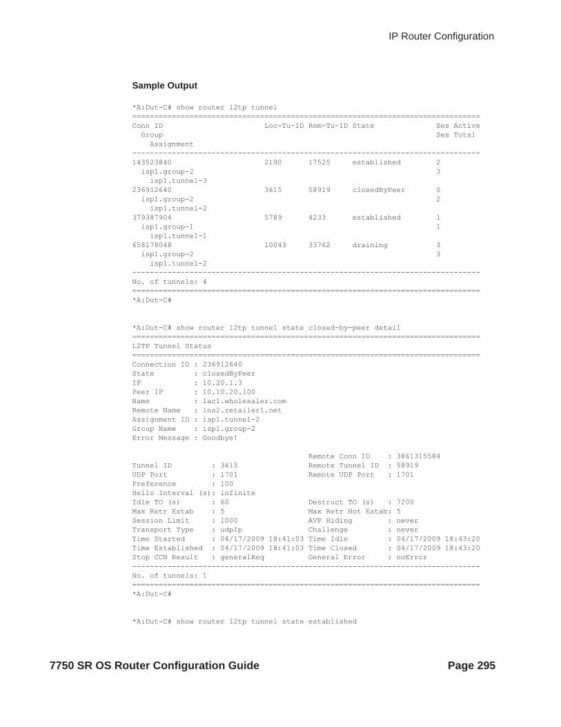
IP Router Configuration
Sample Output
*A:Dut-C# show router l2tp tunnel ===============================================================================Conn ID Loc-Tu-ID Rem-Tu-ID State Ses Active Group Ses Total Assignment-------------------------------------------------------------------------------143523840 2190 17525 established 2 isp1.group-2 3 isp1.tunnel-3236912640 3615 58919 closedByPeer 0 isp1.group-2 2 isp1.tunnel-2379387904 5789 4233 established 1 isp1.group-1 1 isp1.tunnel-1658178048 10043 33762 draining 3 isp1.group-2 3 isp1.tunnel-2-------------------------------------------------------------------------------No. of tunnels: 4===============================================================================*A:Dut-C#
*A:Dut-C# show router l2tp tunnel state closed-by-peer detail ===============================================================================L2TP Tunnel Status===============================================================================Connection ID : 236912640State : closedByPeerIP : 10.20.1.3Peer IP : 10.10.20.100Name : lac1.wholesaler.comRemote Name : lns2.retailer1.netAssignment ID : isp1.tunnel-2Group Name : isp1.group-2Error Message : Goodbye!
Remote Conn ID : 3861315584Tunnel ID : 3615 Remote Tunnel ID : 58919UDP Port : 1701 Remote UDP Port : 1701Preference : 100 Hello Interval (s): infinite Idle TO (s) : 60 Destruct TO (s) : 7200Max Retr Estab : 5 Max Retr Not Estab: 5Session Limit : 1000 AVP Hiding : neverTransport Type : udpIp Challenge : neverTime Started : 04/17/2009 18:41:03 Time Idle : 04/17/2009 18:43:20Time Established : 04/17/2009 18:41:03 Time Closed : 04/17/2009 18:43:20Stop CCN Result : generalReq General Error : noError-------------------------------------------------------------------------------No. of tunnels: 1===============================================================================*A:Dut-C#
*A:Dut-C# show router l2tp tunnel state established
7750 SR OS Router Configuration Guide Page 295

Show Commands
===============================================================================Conn ID Loc-Tu-ID Rem-Tu-ID State Ses Active Group Ses Total Assignment-------------------------------------------------------------------------------143523840 2190 17525 established 2 isp1.group-2 3 isp1.tunnel-3379387904 5789 4233 established 1 isp1.group-1 1 isp1.tunnel-1-------------------------------------------------------------------------------No. of tunnels: 2===============================================================================*A:Dut-C#
*A:Dut-C# show router l2tp tunnel tunnel-id 2190 statistics ===============================================================================L2TP Tunnel Statistics===============================================================================Connection ID: 143523840------------------------------------------------------------------------------- Attempts Failed Active Total -------------------------------------------------------------------------------Sessions 3 0 2 3 -------------------------------------------------------------------------------------------------------------------------------------------------------------- Rx Tx -------------------------------------------------------------------------------Ctrl Packets 47 47 Ctrl Octets 954 1438 Error Packets 0 0 -------------------------------------------------------------------------------*A:Dut-C#
*A:Dut-C# show router l2tp tunnel connection-id 143523840 statistics ===============================================================================L2TP Tunnel Statistics===============================================================================Connection ID: 143523840------------------------------------------------------------------------------- Attempts Failed Active Total -------------------------------------------------------------------------------Sessions 3 0 2 3 -------------------------------------------------------------------------------------------------------------------------------------------------------------- Rx Tx -------------------------------------------------------------------------------Ctrl Packets 48 48 Ctrl Octets 974 1450 Error Packets 0 0 -------------------------------------------------------------------------------*A:Dut-C#
*A:Dut-C# show router l2tp tunnel remote-tunnel-id 17525 detail ===============================================================================
Page 296 7750 SR OS Router Configuration Guide

IP Router Configuration
L2TP Tunnel Status===============================================================================Connection ID : 143523840State : establishedIP : 10.20.1.3Peer IP : 10.10.20.101Name : lac1.wholesaler.comRemote Name : lns3.retailer1.netAssignment ID : isp1.tunnel-3Group Name : isp1.group-2Error Message : N/A
Remote Conn ID : 1148518400Tunnel ID : 2190 Remote Tunnel ID : 17525UDP Port : 1701 Remote UDP Port : 1701Preference : 100 Hello Interval (s): 300 Idle TO (s) : 0 Destruct TO (s) : 7200Max Retr Estab : 5 Max Retr Not Estab: 5Session Limit : 1000 AVP Hiding : neverTransport Type : udpIp Challenge : neverTime Started : 04/17/2009 18:41:14 Time Idle : N/ATime Established : 04/17/2009 18:41:14 Time Closed : N/AStop CCN Result : noError General Error : noError-------------------------------------------------------------------------------No. of tunnels: 1===============================================================================*A:Dut-C#
*A:Dut-C# show router l2tp tunnel remote-connection-id 1148518400 statistics ===============================================================================L2TP Tunnel Statistics===============================================================================Connection ID: 143523840------------------------------------------------------------------------------- Attempts Failed Active Total -------------------------------------------------------------------------------Sessions 3 0 2 3 -------------------------------------------------------------------------------------------------------------------------------------------------------------- Rx Tx -------------------------------------------------------------------------------Ctrl Packets 50 50 Ctrl Octets 1014 1474 Error Packets 0 0 -------------------------------------------------------------------------------No. of tunnels: 1===============================================================================*A:Dut-C#
*A:Dut-C# show router l2tp tunnel peer 10.10.20.100 state closed-by-peer detail ===============================================================================L2TP Tunnel Status===============================================================================Connection ID : 236912640State : closedByPeerIP : 10.20.1.3
7750 SR OS Router Configuration Guide Page 297

Show Commands
Peer IP : 10.10.20.100Name : lac1.wholesaler.comRemote Name : lns2.retailer1.netAssignment ID : isp1.tunnel-2Group Name : isp1.group-2Error Message : Goodbye!
Remote Conn ID : 3861315584Tunnel ID : 3615 Remote Tunnel ID : 58919UDP Port : 1701 Remote UDP Port : 1701Preference : 100 Hello Interval (s): infinite Idle TO (s) : 60 Destruct TO (s) : 7200Max Retr Estab : 5 Max Retr Not Estab: 5Session Limit : 1000 AVP Hiding : neverTransport Type : udpIp Challenge : neverTime Started : 04/17/2009 18:41:03 Time Idle : 04/17/2009 18:43:20Time Established : 04/17/2009 18:41:03 Time Closed : 04/17/2009 18:43:20Stop CCN Result : generalReq General Error : noError-------------------------------------------------------------------------------No. of tunnels: 1===============================================================================*A:Dut-C#
*A:Dut-C# show router l2tp tunnel group isp1.group-2 ===============================================================================Conn ID Loc-Tu-ID Rem-Tu-ID State Ses Active Group Ses Total Assignment-------------------------------------------------------------------------------143523840 2190 17525 established 2 isp1.group-2 3 isp1.tunnel-3236912640 3615 58919 closedByPeer 0 isp1.group-2 2 isp1.tunnel-2658178048 10043 33762 draining 3 isp1.group-2 3 isp1.tunnel-2-------------------------------------------------------------------------------No. of tunnels: 3===============================================================================*A:Dut-C#
*A:Dut-C# show router l2tp tunnel assignment-id isp1.tunnel-3 state established sta-tistics ===============================================================================L2TP Tunnel Statistics===============================================================================Connection ID: 143523840------------------------------------------------------------------------------- Attempts Failed Active Total -------------------------------------------------------------------------------Sessions 3 0 2 3 -------------------------------------------------------------------------------------------------------------------------------------------------------------- Rx Tx
Page 298 7750 SR OS Router Configuration Guide

IP Router Configuration
-------------------------------------------------------------------------------Ctrl Packets 66 66 Ctrl Octets 1310 1690 Error Packets 0 0 -------------------------------------------------------------------------------No. of tunnels: 1===============================================================================*A:Dut-C#
*A:Dut-C# show router l2tp tunnel local-name lac1.wholesaler.com remote-name lns2.retailer1.net state draining ===============================================================================Conn ID Loc-Tu-ID Rem-Tu-ID State Ses Active Group Ses Total Assignment-------------------------------------------------------------------------------658178048 10043 33762 draining 3 isp1.group-2 3 isp1.tunnel-2-------------------------------------------------------------------------------No. of tunnels: 1===============================================================================*A:Dut-C#
*A:Fden-Dut2-BSA2# show router l2tp tunnel connection-id 600375296 statistics===============================================================================L2TP Tunnel Statistics===============================================================================
Connection ID: 600375296
------------------------------------------------------------------------------- Attempts Failed Active Total-------------------------------------------------------------------------------Sessions 1 0 1 1-------------------------------------------------------------------------------
------------------------------------------------------------------------------- Rx Tx-------------------------------------------------------------------------------Ctrl Packets 6 6Ctrl Octets 553 292Error Packets 0 0-------------------------------------------------------------------------------
------------------------------------------------------------------------------- Accepted Duplicate Out-Of-Wnd-------------------------------------------------------------------------------Fsm Messages 4 0 0-------------------------------------------------------------------------------
------------------------------------------------------------------------------- Unsent Max Unsent Cur Ack Max Ack Cur-------------------------------------------------------------------------------Q Length 1 0 1 0-------------------------------------------------------------------------------
7750 SR OS Router Configuration Guide Page 299

Show Commands
Window Size Cur : 4acceptedMsgType StartControlConnectionRequest : 1 StartControlConnectionConnected : 1 IncomingCallRequest : 1 IncomingCallConnected : 1 ZeroLengthBody : 3originalTransmittedMsgType StartControlConnectionReply : 1 Hello : 2 IncomingCallReply : 1 ZeroLengthBody : 3
last cleared time : N/A===============================================================================
Page 300 7750 SR OS Router Configuration Guide

IP Router Configuration
Clear Commands
router
Syntax router router-instance
Context clear>router
Description This command clears for a the router instance in which they are entered.
Parameters router-instance — Specify the router name or service ID.
Values router-name: Base, management, vpls-managementservice-id: 1 — 2147483647
Default Base
arp
Syntax arp {all | ip-addr | interface {ip-int-name | ip-addr}}
Context clear>router
Description This command clears all or specific ARP entries.
The scope of ARP cache entries cleared depends on the command line option(s) specified.
Parameters all — Clears all ARP cache entries.
ip-addr — Clears the ARP cache entry for the specified IP address.
interface ip-int-name — Clears all ARP cache entries for the IP interface with the specified name.
interface ip-addr — Clears all ARP cache entries for the specified IP interface with the specified IP address.
bfd
Syntax bfd src-ip ip-address dst-ip ip-addressbfd all
Context clear>router
Description This command enables the context to clear bi-directional forwarding (BFD) sessions and statistics.
7750 SR OS Router Configuration Guide Page 301

Clear Commands
session
Syntax session src-ip ip-address dst-ip ip-address
Context clear>router>bfd
Description This command clears BFD sessions.
Parameters src-ip ip-address — Specifies the address of the local endpoint of this BFD session.
dst-ip ip-address — Specifies the address of the remote endpoint of this BFD session.
statistics
Syntax statistics src-ip ip-address dst-ip ip-addressstatistics all
Context clear>router>bfd
Description This command clears BFD statistics.
Parameters src-ip ip-address — Specifies the address of the local endpoint of this BFD session.
dst-ip ip-address — Specifies the address of the remote endpoint of this BFD session.
all — Clears statistics for all BFD sessions.
dhcp
Syntax dhcp
Context clear>router
Description This command enables the context to clear DHCP related information.
dhcp6
Syntax dhcp6
Context clear>router
Description This command enables the context to clear DHCP6 related information.
Page 302 7750 SR OS Router Configuration Guide

IP Router Configuration
forwarding-table
Syntax forwarding-table [slot-number]
Context clear>router
Description This command clears entries in the forwarding table (maintained by the IOMs).
If the slot number is not specified, the command forces the route table to be recalculated.
Parameters slot-number — Clears the specified card slot.
Default all IOMs
Values 1 — 10
grt-lookup
Syntax grt-lookup
Context clear>router
Description This command re-evaluates route policies for GRT.
icmp-redirect-route
Syntax icmp-redirect-route {all | ip-address}
Context clear>router
Description This command deletes routes created as a result of ICMP redirects received on the management interface.
Parameters all — Clears all routes.
ip-address — Clears the routes associated with the specified IP address.
icmp6
Syntax icmp6 allicmp6 globalicmp6 interface interface-name
Context clear>router
Description This command clears ICMP statistics.
Parameters all — Clears all statistics.
global — Clears global statistics.
7750 SR OS Router Configuration Guide Page 303

Clear Commands
interface-name — Clears ICMP6 statistics for the specified interface.
interface
Syntax interface [ip-int-name | ip-addr] [icmp] [urpf-stats] [statistics]
Context clear>router
Description This command clears IP interface statistics.
If no IP interface is specified either by IP interface name or IP address, the command will perform the clear operation on all IP interfaces.
Parameters ip-int-name | ip-addr — The IP interface name or IP interface address.
Default All IP interfaces.
icmp — Specifies to reset the ICMP statistics for the IP interface(s) used for ICMP rate limiting.
urpf-stats — - Resets the statistics associated with uRPF failures.
statistics — - Resets the IP interface traffic statistics.
l2tp
Syntax l2pt
Context clear>router
Description This command enables the context to clear L2PT data.
group
Syntax group tunnel-group-name
Context clear>router>l2tp
Description This command clears L2PT data.
Parameters tunnel-group-name — Specifies a Layer Two Tunneling Protocol Tunnel Group name.
tunnel
Syntax tunnel tunnel-id
Context clear>router>l2tp
Description This command clears L2PT data.
Page 304 7750 SR OS Router Configuration Guide

IP Router Configuration
Parameters tunnel-group-name — Clears L2TP tunnel statistics.
statistics
Syntax statistics
Context clear>router>l2tpclear>router>l2tp>groupclear>router>l2tp> tunnel
Description This command clears statistics for the specified context.
statistics
Syntax statistics [ip-address | ip-int-name]
Context clear>router>dhcpclear>router>dhcp6
Description This command clear statistics for DHCP and DHCP6and DHCP6 relay and snooping statistics.
If no IP address or interface name is specified, then statistics are cleared for all configured interfaces.
If an IP address or interface name is specified, then only data regarding the specified interface is cleared.
Parameters ip-address | ip-int-name — Displays statistics for the specified IP interface.
neighbor
Syntax neighbor {all | ip-address}neighbor [interface ip-int-name | ip-address]
Context clear>router
Description This command clears IPv6 neighbor information.
Parameters all — Clears IPv6 neighbors.
ip-int-name — Clears the specified neighbor interface information.
Values 32 characters maximum
ip-address — Clears the specified IPv6 neighbors.
Values ipv6-address: x:x:x:x:x:x:x:x (eight 16-bit pieces) x:x:x:x:x:x:d.d.d.dx: [0 — FFFF]H
d: [0 — 255]D
7750 SR OS Router Configuration Guide Page 305

Clear Commands
router-advertisement
Syntax router-advertisement allrouter-advertisement [interface interface-name]
Context clear>router
Description This command clears all router advertisement counters.
Parameters all — Clears all router advertisement counters for all interfaces.
interface interface-name — Clear router advertisement counters for the specified interface.
Page 306 7750 SR OS Router Configuration Guide

IP Router Configuration
Debug Commands
destination
Syntax destination trace-destination
Context debug>trace
Description This command specifies the destination to send trace messages.
Parameters trace-destination — The destination to send trace messages.
Values stdout, console, logger, memory
enable
Syntax [no] enable
Context debug>trace
Description This command enables the trace.
The no form of the command disables the trace.
trace-point
Syntax [no] trace-point [module module-name] [type event-type] [class event-class] [task task-name] [function function-name]
Context debug>trace
Description This command adds trace points.
The no form of the command removes the trace points.
router
Syntax router router-instance
Context debug
Description This command configures debugging for a router instance.
Parameters router-instance — Specify the router name or service ID.
Values router-name: Base, management service-id: 1 — 2147483647
7750 SR OS Router Configuration Guide Page 307
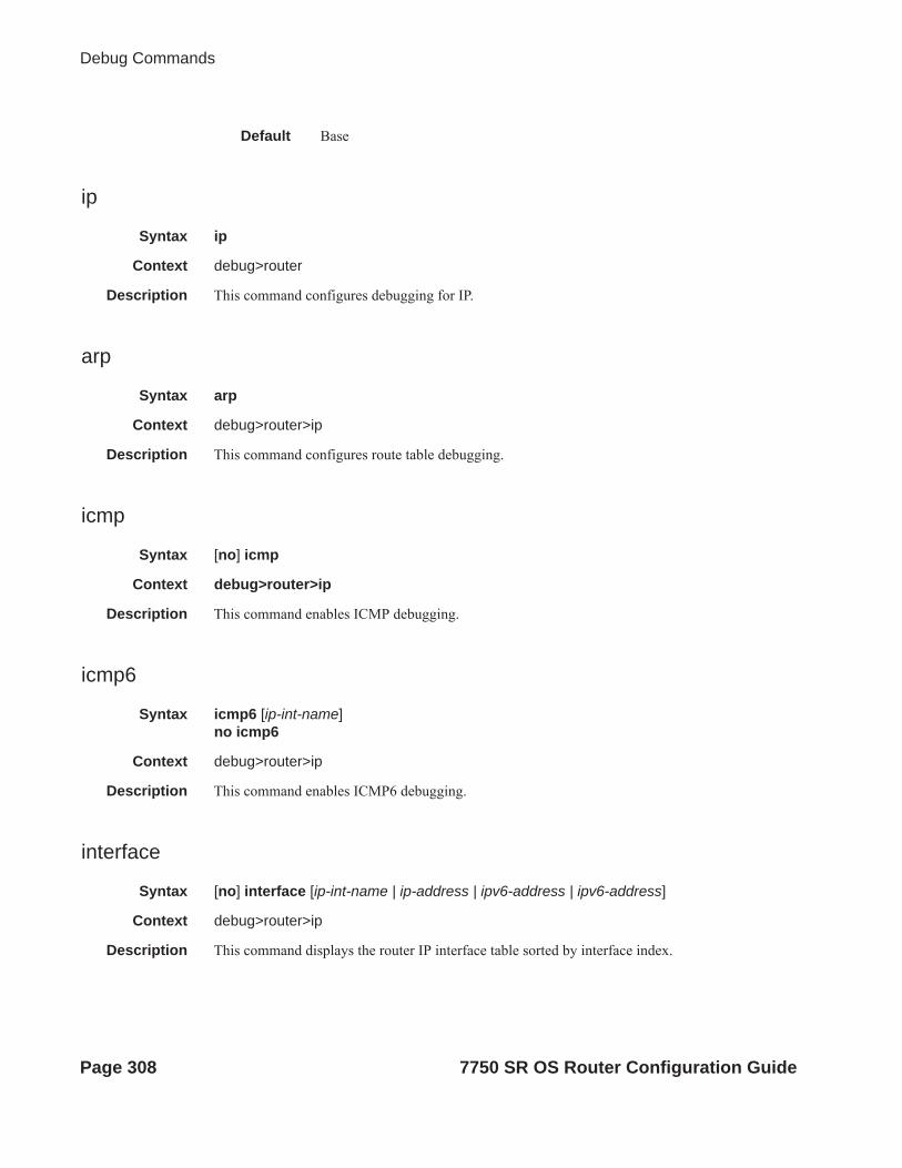
Debug Commands
Default Base
ip
Syntax ip
Context debug>router
Description This command configures debugging for IP.
arp
Syntax arp
Context debug>router>ip
Description This command configures route table debugging.
icmp
Syntax [no] icmp
Context debug>router>ip
Description This command enables ICMP debugging.
icmp6
Syntax icmp6 [ip-int-name]no icmp6
Context debug>router>ip
Description This command enables ICMP6 debugging.
interface
Syntax [no] interface [ip-int-name | ip-address | ipv6-address | ipv6-address]
Context debug>router>ip
Description This command displays the router IP interface table sorted by interface index.
Page 308 7750 SR OS Router Configuration Guide

IP Router Configuration
Parameters ip-address — Only displays the interface information associated with the specified IP address.
Values ipv4-address a.b.c.d (host bits must be 0)ipv6-address x:x:x:x:x:x:x:x (eight 16-bit pieces)
x:x:x:x:x:x:d.d.d.dx: [0 — FFFF]H
d: [0 — 255]D
ip-int-name — Only displays the interface information associated with the specified IP interface name.
Values 32 characters maximum
packet
Syntax packet [ip-int-name | ip-address] [headers] [protocol-id]no packet [ip-int-name | ip-address]
Context debug>router>ip
Description This command enables debugging for IP packets.
Parameters ip-int-name — Only displays the interface information associated with the specified IP interface name.
Values 32 characters maximum
ip-address — Only displays the interface information associated with the specified IP address.
headers — Only displays information associated with the packet header.
protocol-id — Specifies the decimal value representing the IP protocol to debug. Well known protocol numbers include ICMP(1), TCP(6), UDP(17). The no form the command removes the protocol from the criteria.
Values 0 — 255 (values can be expressed in decimal, hexidecimal, or binary)
route-table
Syntax route-table [ip-prefix/prefix-length]route-table ip-prefix/prefix-length longerno route-table
Context debug>router>ip
Description This command configures route table debugging.
Parameters ip-prefix — The IP prefix for prefix list entry in dotted decimal notation.
Values ipv4-prefix a.b.c.d (host bits must be 0)ipv4-prefix-length 0 — 32ipv6-prefix x:x:x:x:x:x:x:x (eight 16-bit pieces)
x:x:x:x:x:x:d.d.d.dx: [0 — FFFF]H
7750 SR OS Router Configuration Guide Page 309

Debug Commands
d: [0 — 255]Dipv6-prefix-length 0 — 128
longer — Specifies the prefix list entry matches any route that matches the specified ip-prefix and pre-fix mask length values greater than the specified mask.
tunnel-table
Syntax tunnel-table [ip-address] [ldp | rsvp [tunnel-id tunnel-id]| sdp [sdp-id sdp-id]]
Context debug>router>ip
Description This command enables debugging for tunnel tables.
mtrace
Syntax [no] mtrace
Context debug>router
Description This command configures debugging for mtrace.
tms
Syntax [no] tms [interface <tms-interface>] api [detail] <tms-interface>
Context debug>router
Description This command configures debugging for Threat Management Services.
misc
Syntax [no] misc
Context debug>router>mtrace
Description This command enables debugging for mtrace miscellaneous.
packet
Syntax [no] packet [query | request | response]
Context debug>router>mtrace
Description This command enables debugging for mtrace packets.
Page 310 7750 SR OS Router Configuration Guide

IP Router Configuration
7750 SR OS Router Configuration Guide Page 311

Debug Commands
Page 312 7750 SR OS Router Configuration Guide

VRRP
In This ChapterThis chapter provides information about configuring Virtual Router Redundancy Protocol (VRRP) parameters. Topics in this chapter include:
• VRRP Overview on page 314 Virtual Router on page 315 IP Address Owner on page 315 Primary and Secondary IP Addresses on page 316 Virtual Router Master on page 316 Virtual Router Backup on page 317 Owner and Non-Owner VRRP on page 317 Configurable Parameters on page 318
• VRRP Priority Control Policies on page 326 VRRP Virtual Router Policy Constraints on page 326 VRRP Virtual Router Instance Base Priority on page 326 VRRP Priority Control Policy Delta In-Use Priority Limit on page 327 VRRP Priority Control Policy Priority Events on page 328
• VRRP Non-Owner Accessibility on page 334 Non-Owner Access Ping Reply on page 334 Non-Owner Access Telnet on page 334 Non-Owner Access SSH on page 335 VRRP Advertisement Message IP Address List Verification on page 324
• VRRP Configuration Process Overview on page 336• Configuration Notes on page 337
7750 SR OS Router Configuration Guide Page 313
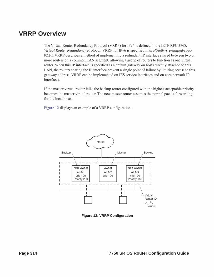
VRRP OverviewThe Virtual Router Redundancy Protocol (VRRP) for IPv4 is defined in the IETF RFC 3768, Virtual Router Redundancy Protocol. VRRP for IPv6 is specified in draft-ietf-vrrp-unified-spec-02.txt. VRRP describes a method of implementing a redundant IP interface shared between two or more routers on a common LAN segment, allowing a group of routers to function as one virtual router. When this IP interface is specified as a default gateway on hosts directly attached to this LAN, the routers sharing the IP interface prevent a single point of failure by limiting access to this gateway address. VRRP can be implemented on IES service interfaces and on core network IP interfaces.
If the master virtual router fails, the backup router configured with the highest acceptable priority becomes the master virtual router. The new master router assumes the normal packet forwarding for the local hosts.
Figure 12 displays an example of a VRRP configuration.
Figure 12: VRRP Configuration
OSRG006
Non-Owner
ALA-3
vrld 100
Priority 150
Owner
ALA-2
vrld 100
Non-Owner
ALA-1
vrld 100
Priority 200
Internet
Backup Master Backup
Virtual
Router ID
(VRID)
Page 314 7750 SR OS Router Configuration Guide

VRRP
VRRP ComponentsVRRP consists of the following components:
• Virtual Router on page 315• IP Address Owner on page 315• Primary and Secondary IP Addresses on page 316• Virtual Router Master on page 316• Virtual Router Backup on page 317• Owner and Non-Owner VRRP on page 317
Virtual Router
A virtual router is a logical entity managed by VRRP that acts as a default router for hosts on a shared LAN. It consists of a Virtual Router Identifier (VRID) and a set of associated IP addresses (or address) across a common LAN. A VRRP router can backup one or more virtual routers.
The purpose of supporting multiple IP addresses within a single virtual router is for multi-netting. This is a common mechanism that allows multiple local subnet attachment on a single routing interface. Up to four virtual routers are possible on a single Alcatel-Lucent IP interface. The virtual routers must be in the same subnet. Each virtual router has its own VRID, state machine and messaging instance.
IP Address Owner
VRRP can be configured in either an owner or non-owner mode. The owner is the VRRP router whose virtual router IP address is the same as the real interface IP address. This is the router that responds to packets addressed to one of the IP addresses for ICMP pings, TCP connections, etc. All other virtual router instances participating in this message domain must have the same VRID configured and cannot be configured as owner.
Alcatel-Lucent routers allow the virtual routers to be configured as non-owners of the IP address. VRRP on a router can be configured to allow non-owners to respond to ICMP echo requests when they become the virtual router master for the virtual router. Telnet and other connection-oriented protocols can also be configured for non-owner master response. However, the individual application conversations (connections) will not survive a VRRP failover. A non-owner VRRP
7750 SR OS Router Configuration Guide Page 315

router operating as a backup will not respond to any packets addressed to any of the virtual router IP addresses.
Primary and Secondary IP Addresses
A primary address is an IP address selected from the set of real interface address. VRRP advertisements are always sent using the primary IP address as the source of the IP packet.
An IP interface must always have a primary IP address assigned for VRRP to be active on the interface. Alcatel-Lucent routers supports both primary and secondary IP addresses (multi-netting) on the IP interface. The virtual router’s VRID primary IP address is always the primary address on the IP interface. VRRP uses the primary IP address as the IP address placed in the source IP address field of the IP header for all VRRP messages sent on that interface.
Virtual Router Master
The VRRP router which controls the IP address(es) associated with a virtual router is called the master. The master is responsible for forwarding packets sent to the VRRP IP addresses. An election process provides dynamic failover of the forwarding responsibility if the master becomes unavailable. This allows any of the virtual router IP addresses on the LAN to be used as the default first hop router by end hosts. This enables a higher availability default path without requiring configuration of dynamic routing or router discovery protocols on every end host.
If the master is unavailable, each backup virtual router for the VRID compare the configured priority values to determine the master role. In case of a tie, the virtual router with the highest primary IP address becomes master.
The preempt parameter can be set to false to prevent a backup virtual router with a better priority value from becoming master when an existing non-owner virtual router is the current master. This is determined on a first-come, first-served basis.
While master, a virtual router routes and originates all IP packets into the LAN using the physical MAC address for the IP interface as the Layer 2 source MAC address, not the VRID MAC address. ARP packets also use the parent IP interface MAC address as the Layer 2 source MAC address while inserting the virtual router MAC address in the appropriate hardware address field. VRRP messages are the only packets transmitted using the virtual router MAC address as the Layer 2 source MAC.
Page 316 7750 SR OS Router Configuration Guide

VRRP
Virtual Router Backup
A new virtual router master is selected from the set of VRRP routers available to assume forwarding responsibility for a virtual router should the current master fail.
Owner and Non-Owner VRRP
The owner controls the IP address of the virtual router and is responsible for forwarding packets sent to this IP address. The owner assumes the role of the master virtual router. Only one virtual router in the domain can be configured as owner. All other virtual router instances participating in this message domain must have the same VRID configured.
The most important parameter to be defined on a non-owner virtual router instance is the priority. The priority defines a virtual router’s selection order in the master election process. The priority value and the preempt mode determine the virtual router with the highest priority to become the master virtual router.
The base priority is used to derive the in-use priority of the virtual router instance as modified by any optional VRRP priority control policy. VRRP priority control policies can be used to either override or adjust the base priority value depending on events or conditions within the chassis.
For information about non-owner access parameters, refer to VRRP Non-Owner Accessibility on page 334.
7750 SR OS Router Configuration Guide Page 317

Configurable Parameters
In addition to backup IP addresses, to facilitate configuration of a virtual router on Alcatel-Lucent routers, the following parameters can be defined in owner configurations:
• Virtual Router ID (VRID) on page 318• Message Interval and Master Inheritance on page 320• VRRP Message Authentication on page 322• Authentication Data on page 324• Virtual MAC Address on page 324
The following parameters can be defined in non-owner configurations:
• Virtual Router ID (VRID) on page 318• Priority on page 318• Message Interval and Master Inheritance on page 320• Master Down Interval on page 321• Preempt Mode on page 321• VRRP Message Authentication on page 322• Authentication Data on page 324• Virtual MAC Address on page 324• Inherit Master VRRP Router’s Advertisement Interval Timer on page 325• Policies on page 325
Virtual Router ID (VRID)
The VRID must be configured with the same value on each virtual router associated with the redundant IP address (IP addresses). It is placed in all VRRP advertisement messages sent by each virtual router.
Priority
The priority value affects the interaction between this VRID and the same VRID of other virtual routers participating on the same LAN. A higher priority value defines a greater priority in becoming the virtual router master for the VRID. The priority value can only be configured when
Page 318 7750 SR OS Router Configuration Guide

VRRP
the defined IP address on the IP interface is different than the virtual router IP address (non-owner mode).
When the IP address on the IP interface matches the virtual router IP address (owner mode), the priority value is fixed at 255, the highest value possible. This virtual router member is considered the owner of the virtual router IP address. There can only be one owner of the virtual router IP address for all virtual router members.
The priority value 0 is reserved for VRRP advertisement message purposes. It is used to tell other virtual routers in the same VRID that this virtual router is no longer acting as master, triggering a new election process. When this happens, each backup virtual router sets its master down timer equal to the skew time value. This shortens the time until one of the backup virtual routers becomes master.
The current master virtual router must transmit a VRRP advertisement message immeediately upon receipt of a VRRP message with priority set to 0. This prevents another backup from becoming master for a short period of time.
Non-owner virtual routers may be configured with a priority of 254 through 1. The default value is 100. Multiple non-owners can share the same priority value. When multiple non-owner backup virtual routers are tied (transmit VRRP advertisement messages simultaneously) in the election process, both become master simultaneously, the one with the best priority will win the election. If the priority value in the message is equal to the master’s local priority value, then the primary IP address of the local master and the message is evaluated as the tie breaker. The higher IP address becomes master. (The primary IP address is the source IP address of the VRRP advertisement message.)
The priority is also used to determine when to preempt the existing master. If the preempt mode value is true, VRRP advertisement messages from inferior (lower priority) masters are discarded, causing the master down timer to expire and the transition to master state.
The priority value also dictates the skew time added to the master timeout period.
IP Addresses
Each virtual router participating in the same VRID should be defined with the same set of IP addresses. These are the IP addresses being used by hosts on the LAN as gateway addresses. Multi-netting supports 16 IP addresses on the IP interface, up to 16 addresses can be assigned to a specific a virtual router instance.
7750 SR OS Router Configuration Guide Page 319

Message Interval and Master Inheritance
Each virtual router is configured with a message interval per VRID within which it participates. This parameter must be the same for every virtual router on the VRID.
For IPv4, the default advertisement interval is 1 second and can be configured between 100 milliseconds and 255 seconds 900 milliseconds. For IPv6, the default advertisement interval is 1 second and can be configured between 100 milliseconds and 40 seconds 950 milliseconds.
As specified in the RFC, the advertisement interval field in every received VRRP advertisement message must match the locally configured advertisement interval. If a mismatch occurs, depending on the inherit configuration, the current master's advertisement interval setting can be used to operationally override the locally configured advertisement interval setting. If the current master changes, the new master setting is used. If the local virtual router becomes master, the locally configured advertisement interval is enforced.
If a VRRP advertisement message is received with an advertisement interval set to a value different than the local value and the inherit parameter is disabled, the message is discarded without processing.
The master virtual router on a VRID uses the advertisement interval to load the advertisement timer, specifying when to send the next VRRP advertisement message. Each backup virtual router on a VRID uses the advertisement interval (with the configured local priority) to derive the master down timer value.
VRRP advertisements messages that are fragmented, contain IP options (IPv4), or contain extension headers (IPv6) require a longer message interval to be configured.
Skew Time
The skew time is used to add a time period to the master down interval. This is not a configurable parameter. It is derived from the current local priority of the virtual router’s VRID. To calculate the skew time, the virtual router evaluates the following formula:
For IPv4: Skew Time = ((256 - priority) / 256) seconds
For IPv6: Skew Time = (((256 - priority) * Master_Adver_Interval) / 256) centiseconds
The higher priority value, the smaller the skew time will be. This means that virtual routers with a lower priority will transition to master slower than virtual routers with higher priorities.
Page 320 7750 SR OS Router Configuration Guide
VRRP
Master Down Interval
The master down interval is a calculated value used to load the master down timer. When the master down timer expires, the virtual router enters the master state. To calculate the master down interval, the virtual router evaluates the following formula:
Master Down Interval = (3 x Operational Advertisement Interval) + Skew Time
The operational advertisement interval is dependent upon the state of the inherit parameter. When the inherit parameter is enabled, the operational advertisement interval is derived from the current master’s advertisement interval field in the VRRP advertisement message. When inherit is disabled, the operational advertisement interval must be equal to the locally configured advertisement interval.
The master down timer is only operational when the local virtual router is operating in backup mode.
Preempt Mode
Preempt mode is a true or false configured value which controls whether a specific backup virtual router preempts a lower priority master. The IP address owner will always become master when available. Preempt mode cannot be set to false on the owner virtual router. The default value for preempt mode is true.
When preempt mode is true, the advertised priority from the incoming VRRP advertisement message from the current master is compared to the local configured priority. If the local priority is higher, the received VRRP advertisement message is discarded. This will result in the eventual expiration of the master down timer causing a transition to the master state. If the received priority is equal to the local priority, the message is not discarded and the current master will not be discarded. Note that when in the backup state, the received primary IP address is not part of the decision to preempt and is not used as a tie breaker when the received and local priorities are equal.
When preempt is enabled, the virtual router instance overrides any non-owner master with an in-use message priority value less than the virtual router instance in-use priority value. If preempt is disabled, the virtual router only becomes master if the master down timer expires before a VRRP advertisement message is received from another virtual router.
7750 SR OS Router Configuration Guide Page 321

VRRP Message Authentication
The authentication type parameter defines the type of authentication used by the virtual router in VRRP advertisement message authentication. VRRP message authentication is applicable to IPv4 only. The current master uses the configured authentication type to indicate any egress message manipulation that must be performed in conjunction with any supporting authentication parameters before transmitting a VRRP advertisement message. The configured authentication type value is transmitted in the message authentication type field with the appropriate authentication data field filled in. Backup routers use the authentication type message field value in interpreting the contained authentication data field within received VRRP advertisement messages.
VRRP supports three message authentication methods which provide varying degrees of security. The supported authentication types are:
0 – No Authentication1 – Simple Text Password2 – IP Authentication Header
Authentication Type 0 – No Authentication
The use of type 0 indicates that VRRP advertisement messages are not authenticated (provides no authentication). The master transmitting VRRP advertisement messages will transmit the value 0 in the egress messages authentication type field and the authentication data field. Backup virtual routers receiving VRRP advertisement messages with the authentication type field equal to 0 will ignore the authentication data field in the message.
All compliant VRRP advertisement messages are accepted. The following fields within the received VRRP advertisement message are checked for compliance (the VRRP specification may require additional checks).
• IP header checks specific to VRRP IP header destination IP address – Must be 224.0.0.18 IP header TTL field – Must be equal to 255, the packet must not have traversed any IP
routed hops IP header protocol field – must be 112 (decimal)
Page 322 7750 SR OS Router Configuration Guide

VRRP
• VRRP message checks Version field – Must be set to the value 2 Type field – Must be set to the value of 1 (advertisement) Virtual router ID field – Must match one of the configured VRID on the ingress IP
interface (All other fields are dependent on matching the virtual router ID field to one of the interfaces configured VRID parameters)
Priority field – Must be equal to or greater than the VRID in-use priority or be equal to 0 (Note, equal to the VRID in-use priority and 0 requires further processing regarding master/backup and senders IP address to determine validity of the message)
Authentication type field – Must be equal to 0 Advertisement interval field – Must be equal to the VRID configured advertisement
interval Checksum field – Must be valid Authentication data fields – Must be ignored.
VRRP messages not meeting the criteria are silently dropped.
Authentication Type 1 – Simple Text Password
The use of type 1 indicates that VRRP advertisement messages are authenticated with a clear (simple) text password. All virtual routers participating in the virtual router instance must be configured with the same 8 octet password. Transmitting virtual routers place a value of 1 in the VRRP advertisement message authentication type field and put the configured simple text password into the message authentication data field. Receiving virtual routers compare the message authentication data field with the local configured simple text password based on the message authentication type field value of 1.
The same checks are performed for type 0 with the following exceptions (the VRRP specification may require additional checks):
• VRRP message checks Authentication type field – Must be equal to 1 Authentication data fields – Must be equal to the VRID configured simple text
password
Any VRRP message not meeting the type 0 verification checks with the exceptions above are silently discarded.
7750 SR OS Router Configuration Guide Page 323

Authentication Failure
Any received VRRP advertisement message that fails authentication must be silently discarded with an invalid authentication counter incremented for the ingress virtual router instance.
Authentication Data
This feature is different than the VRRP advertisement message field with the same name. This is any required authentication information that is pertinent to the configured authentication type. The type of authentication data used for each authentication type is as follows:
Authentication Type Authentication Data0 None, authentication is not performed1 Simple text password consisting of 8 octets
Virtual MAC Address
The MAC address can be used instead of an IP address in ARP responses when the virtual router instance is master. The MAC address configuration must be the same for all virtual routers participating as a virtual router or indeterminate connectivity by the attached IP hosts will result. All VRRP advertisement messages are transmitted with ieee-mac-addr as the source MAC.
VRRP Advertisement Message IP Address List Verification
VRRP advertisement messages contain an IP address count field that indicates the number of IP addresses listed in the sequential IP address fields at the end of the message.
The Alcatel-Lucent routersimplementation always logs mismatching events. The decision on where and whether to forward the generated messages depends on the configuration of the event manager.
To facilitate the sending of mismatch log messages, each virtual router instance keeps the mismatch state associated with each source IP address in the VRRP master table. Whenever the state changes, a mismatch log message is generated indicating the source IP address within the message, the mismatch or match event and the time of the event.
Page 324 7750 SR OS Router Configuration Guide

VRRP
With secondary IP address support, multiple IP addresses may be found in the list and it should match the IP address on the virtual router instance. Owner and non-owner virtual router instances have the supported IP addresses explicitly defined, making mismatched supported IP address within the interconnected virtual router instances a provisioning issue.
Inherit Master VRRP Router’s Advertisement Interval Timer
The virtual router instance can inherit the master VRRP router’s advertisement interval timer which is used by backup routers to calculate the master down timer.
The inheritance is only configurable in the non-owner nodal context. It is used to allow the current virtual router instance master to dictate the master down timer for all backup virtual routers.
IPv6 Virtual Router Instance Operationally Up
Once the IPv6 virtual router is properly configured with a minimum of one link-local backup address, the parent interface’s router advertisement must be configured to use the virtual MAC address for the virtual router to be considered operationally up.
Policies
Policies can be configured to control VRRP priority with the virtual router instance. VRRP priority control policies can be used to override or adjust the base priority value depending on events or conditions within the chassis.
The policy can be associated with more than one virtual router instance. The priority events within the policy override or diminish the base priority dynamically affecting the in-use priority. As priority events clear in the policy, the in-use priority can eventually be restored to the base priority value.
Policies can only be configured in the non-owner VRRP context. For non-owner virtual router instances, if policies are not configured, then the base priority is used as the in-use priority.
7750 SR OS Router Configuration Guide Page 325
VRRP Priority Control PoliciesThis implementation of VRRP supports control policies to manipulate virtual router participation in the VRRP master election process and master self-deprecation. The local priority value for the virtual router instance is used to control the election process and master state.
VRRP Virtual Router Policy Constraints
Priority control policies can only be applied to non-owner VRRP virtual router instances. Owner VRRP virtual routers cannot be controlled by a priority control policy because they are required to have a priority value of 255 that cannot be diminished. Only one VRRP priority control policy can be applied to a non-owner virtual router instance.
Multiple VRRP virtual router instances may be associated with the same IP interface, allowing multiple priority control policies to be associated with the IP interface.
An applied VRRP priority control policy only affects the in-use priority on the virtual router instance when the preempt mode has been enabled. A virtual router instance with preempt mode disabled will always use the base priority as the in-use priority, ignoring any configured priority control policy.
VRRP Virtual Router Instance Base Priority
Non-owner virtual router instances must have a base priority value between 1 and 254. The value 0 is reserved for master termination. The value 255 is reserved for owners. The default base priority for non-owner virtual router instances is the value 100.
The base priority is the starting priority for the VRRP instance. The actual in-use priority for the VRRP instance is derived from the base priority and an optional VRRP priority control policy.
Page 326 7750 SR OS Router Configuration Guide

VRRP
VRRP Priority Control Policy Delta In-Use Priority Limit
A VRRP priority control policy enforces an overall minimum value that the policy can inflict on the VRRP virtual router instance base priority. This value provides a lower limit to the delta priority events manipulation of the base priority.
A delta priority event is a conditional event defined in the priority control policy that subtracts a given amount from the current, in-use priority for all VRRP virtual router instances to which the policy is applied. Multiple delta priority events can apply simultaneously, creating a dynamic priority value. The base priority for the instance, less the sum of the delta values derives the actual priority value in-use.
An explicit priority event is a conditional event defined in the priority control policy that explicitly defines the in-use priority for the virtual router instance. The explicitly defined values are not affected by the delta in-use priority limit. When multiple explicit priority events happen simultaneously, the lowest value is used for the in-use priority. The configured base priority is not a factor in explicit priority overrides of the in-use priority.
The allowed range of the Delta In-Use Priority Limit is 1 to 254. The default is 1, which prevents the delta priority events from operationally disabling the virtual router instance.
7750 SR OS Router Configuration Guide Page 327

VRRP Priority Control Policy Priority Events
The main function of a VRRP priority control policy is to define conditions or events that impact the system’s ability to communicate with outside hosts or portions of the network. When one or multiple of these events are true, the base priority on the virtual router instance is either overwritten with an explicit value, or a sum of delta priorities is subtracted from the base priority. The result is the in-use priority for the virtual router instance. Any priority event may be configured as an explicit event or a delta event.
Explicit events override all delta events. When multiple explicit events occur, the event with the lowest priority value is assigned to the in-use priority. As events clear, the in-use priority is reevaluated accordingly and adjusted dynamically.
Delta priority events also have priority values. When no explicit events have occurred within the policy, the sum of the occurring delta events priorities is subtracted from the base priority of each virtual router instance. If the result is lower than the delta in-use priority limit, the delta in-use priority limit is used as the in-use priority for the virtual router instance. Otherwise, the in-use priority is set to the base priority less the sum of the delta events.
Each event generates a VRRP priority event message indicating the policy-id, the event type, the priority type (delta or explicit) and the event priority value. Another log message is generated when the event is no longer true, indicating that it has been cleared.
Priority Event Hold-Set Timers
Hold-set timers are used to dampen the effect of a flapping event. A flapping event is where the event continually transitions between clear and set. The hold-set value is loaded into a hold set timer that prevents a set event from transitioning to the cleared state until it expires.
Each time an event transitions between cleared and set, the timer is loaded and begins to count down to zero. If the timer reaches zero, the event will be allowed to enter the cleared state once more. Entering the cleared state is always dependent on the object controlling the event conforming to the requirements defined in the event itself. It is possible, on some event types, to have a further set action reload the hold set timer. This extends the amount of time that must expire before entering the cleared state.
For an example of a hold-set timer setting, refer to LAG Degrade Priority Event on page 329.
Page 328 7750 SR OS Router Configuration Guide

VRRP
Port Down Priority Event
The port down priority event is tied to either a physical port or a SONET/SDH channel. The port or channel operational state is evaluated to determine a port down priority event or event clear.
When the port or channel operational state is up, the port down priority event is considered false or cleared. When the port or channel operational state is down, the port down priority event is considered true or set.
LAG Degrade Priority Event
The LAG degrade priority event is tied to an existing Link Aggregation Group (LAG). The LAG degrade priority event is conditional to percentage of available port bandwidth on the LAG. Multiple bandwidth percentage thresholds may be defined, each with its own priority value.
If the LAG transitions from one threshold to the next, the previous threshold priority value is subtracted from the total delta sum while the new threshold priority value is added to the sum. The new sum is then subtracted from the base priority and compared to the delta in-use priority limit to derive the new in-use priority on the virtual router instance.
The following example illustrates a LAG priority event and it’s interaction with the hold set timer in changing the in-use priority.
The following state and timer settings are used for the LAG events displayed in Table 6:
• User-defined thresholds: 2 ports down 4 ports down 6 ports down• LAG configured ports: 8 ports• Hold set timer (hold-set): 5 seconds
Table 6: LAG Events
Time LAG Port State Parameter State Comments
0 All ports down Event State Set - 8 ports down
Event Threshold 6 ports down
Hold Set Timer 5 seconds Set to hold-set parameter
7750 SR OS Router Configuration Guide Page 329
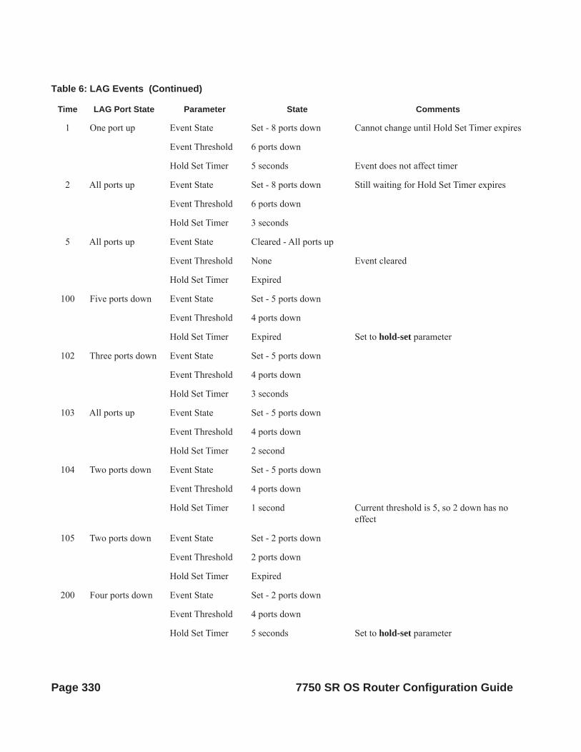
1 One port up Event State Set - 8 ports down Cannot change until Hold Set Timer expires
Event Threshold 6 ports down
Hold Set Timer 5 seconds Event does not affect timer
2 All ports up Event State Set - 8 ports down Still waiting for Hold Set Timer expires
Event Threshold 6 ports down
Hold Set Timer 3 seconds
5 All ports up Event State Cleared - All ports up
Event Threshold None Event cleared
Hold Set Timer Expired
100 Five ports down Event State Set - 5 ports down
Event Threshold 4 ports down
Hold Set Timer Expired Set to hold-set parameter
102 Three ports down Event State Set - 5 ports down
Event Threshold 4 ports down
Hold Set Timer 3 seconds
103 All ports up Event State Set - 5 ports down
Event Threshold 4 ports down
Hold Set Timer 2 second
104 Two ports down Event State Set - 5 ports down
Event Threshold 4 ports down
Hold Set Timer 1 second Current threshold is 5, so 2 down has no effect
105 Two ports down Event State Set - 2 ports down
Event Threshold 2 ports down
Hold Set Timer Expired
200 Four ports down Event State Set - 2 ports down
Event Threshold 4 ports down
Hold Set Timer 5 seconds Set to hold-set parameter
Table 6: LAG Events (Continued)
Time LAG Port State Parameter State Comments
Page 330 7750 SR OS Router Configuration Guide

VRRP
1 One port up Event State Set - 8 ports down Cannot change until Hold Set Timer expires
Event Threshold 6 ports down
Hold Set Timer 5 seconds Event does not affect timer
2 All ports up Event State Set - 8 ports down Still waiting for Hold Set Timer expires
Event Threshold 6 ports down
Hold Set Timer 3 seconds
5 All ports up Event State Cleared - All ports up
Event Threshold None Event cleared
Hold Set Timer Expired
100 Five ports down Event State Set - 5 ports down
Event Threshold 4 ports down
Hold Set Timer Expired Set to hold-set parameter
102 Three ports down Event State Set - 5 ports down
Event Threshold 4 ports down
Hold Set Timer 3 seconds
103 All ports up Event State Set - 5 ports down
Event Threshold 4 ports down
Hold Set Timer 2 second
104 Two ports down Event State Set - 5 ports down
Event Threshold 4 ports down
Hold Set Timer 1 second Current threshold is 5, so 2 down has no effect
105 Two ports down Event State Set - 2 ports down
Event Threshold 2 ports down
Hold Set Timer Expired
200 Four ports down Event State Set - 2 ports down
Event Threshold 4 ports down
Hold Set Timer 5 seconds Set to hold-set parameter
Table 6: LAG Events (Continued)
Time LAG Port State Parameter State Comments
7750 SR OS Router Configuration Guide Page 331

Host Unreachable Priority Event
The host unreachable priority event creates a continuous ping task that is used to test connectivity to a remote host. The path to the remote host and the remote host itself must be capable and configured to accept ICMP echo request and replies for the ping to be successful.
The ping task is controlled by interval and size parameters that define how often the ICMP request messages are transmitted and the size of each message. A historical missing reply parameter defines when the ping destination is considered unreachable.
When the host is unreachable, the host unreachable priority event is considered true or set. When the host is reachable, the host unreachable priority event is considered false or cleared.
Route Unknown Priority Event
The route unknown priority event defines a task that monitors the existence of a given route prefix in the system’s routing table.
The route monitoring task can be constrained by a condition that allows a prefix that is less specific than the defined prefix to be considered as a match. The source protocol can be defined to indicate the protocol the installed route must be populated from. To further define match criteria when multiple instances of the route prefix exist, an optional next hop parameter can be defined.
202 Seven ports down Event State Set - 7 ports down Changed due to increase
Event Threshold 6 ports down
Hold Set Timer 5 seconds Set to hold-set due to threshold increase
206 All ports up Event State Set - 7 ports down
Event Threshold 6 ports down
Hold Set Timer 1 second
207 All ports up Event State Cleared - All ports up
Event Threshold None Event cleared
Hold Set Timer Expired
Table 6: LAG Events (Continued)
Time LAG Port State Parameter State Comments
Page 332 7750 SR OS Router Configuration Guide

VRRP
When a route prefix exists within the active route table that matches the defined match criteria, the route unknown priority event is considered false or cleared. When a route prefix does not exist within the active route table matching the defined criteria, the route unknown priority event is considered true or set.
7750 SR OS Router Configuration Guide Page 333

VRRP Non-Owner AccessibilityAlthough the RFC states that only VRRP owners can respond to ping and other management-oriented protocols directed to the VRID IP addresses, the routers allow an override of this restraint on a per VRRP virtual router instance basis.
Non-Owner Access Ping Reply
When non-owner access ping reply is enabled on a virtual router instance, ICMP echo request messages destined to the non-owner virtual router instance IP addresses are not discarded at the IP interface when operating in master mode. ICMP echo request messages are always discarded in backup mode.
When non-owner access ping reply is disabled on a virtual router instance, ICMP echo request messages destined to the non-owner virtual router instance IP addresses are silently discarded in both the master and backup modes.
Non-Owner Access Telnet
When non-owner access Telnet is enabled on a virtual router instance, authorized Telnet sessions may be established that are destined to the virtual router instance IP addresses when operating in master mode. Telnet sessions are always discarded at the IP interface when destined to a virtual router IP address operating in backup mode. Enabling non-owner access Telnet does not guarantee Telnet access, proper management and security features must be enabled to allow Telnet on this interface and possibly from the given source IP address.
When non-owner access Telnet is disabled on a virtual router instance, Telnet sessions destined to the non-owner virtual router instance IP addresses are silently discarded in both master and backup modes.
Page 334 7750 SR OS Router Configuration Guide

VRRP
Non-Owner Access SSH
When non-owner access SSH is enabled on a virtual router instance, authorized SSH sessions may be established that are destined to the virtual router instance IP addresses when operating in master mode. SSH sessions are always discarded at the IP interface when destined to a virtual router IP address operating in backup mode. Enabling non-owner access SSH does not guarantee SSH access, proper management and security features must be enabled to allow SSH on this interface and possibly from the given source IP address. SSH is applicable to IPv4 VRRP only.
When non-owner access SSH is disabled on a virtual router instance, SSH sessions destined to the non-owner virtual router instance IP addresses are silently discarded in both master and backup modes.
7750 SR OS Router Configuration Guide Page 335
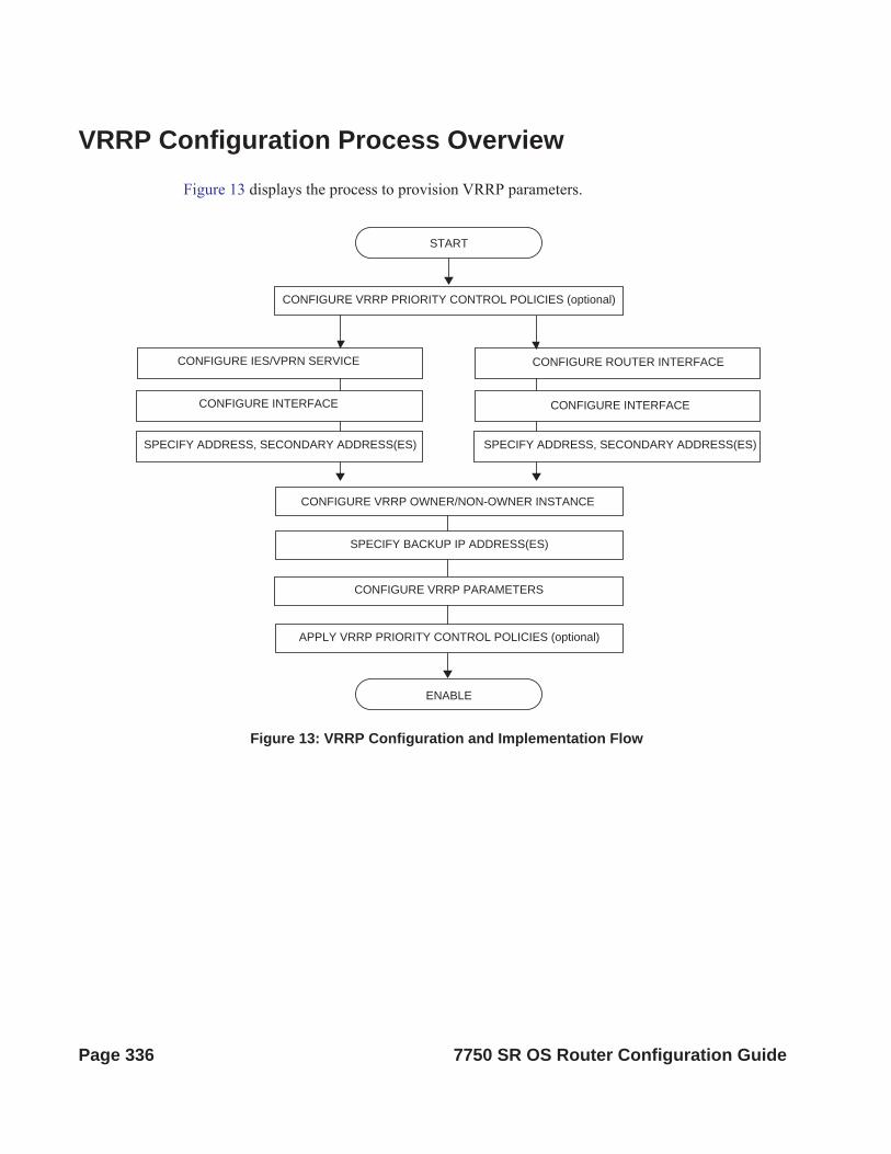
VRRP Configuration Process OverviewFigure 13 displays the process to provision VRRP parameters.
Figure 13: VRRP Configuration and Implementation Flow
ENABLE
START
CONFIGURE VRRP PRIORITY CONTROL POLICIES (optional)
CONFIGURE IES/VPRN SERVICE CONFIGURE ROUTER INTERFACE
CONFIGURE INTERFACE CONFIGURE INTERFACE
SPECIFY ADDRESS, SECONDARY ADDRESS(ES) SPECIFY ADDRESS, SECONDARY ADDRESS(ES)
APPLY VRRP PRIORITY CONTROL POLICIES (optional)
SPECIFY BACKUP IP ADDRESS(ES)
CONFIGURE VRRP OWNER/NON-OWNER INSTANCE
CONFIGURE VRRP PARAMETERS
Page 336 7750 SR OS Router Configuration Guide

VRRP
Configuration NotesThis section describes VRRP configuration caveats.
General
• Creating and applying VRRP policies are optional.• Backup command:
The backup IP address(es) must be on the same subnet. The backup addresses explicitly define which IP addresses are in the VRRP advertisement message IP address list.
In the owner mode, the backup IP address must be identical to one of the interface’s IP addresses. The backup address explicitly defines which IP addresses are in the VRRP advertisement message IP address list.
For IPv6, one of the backup addresses configured must be the link-local address of the owner VRRP instance.
7750 SR OS Router Configuration Guide Page 337

Page 338 7750 SR OS Router Configuration Guide

VRRP
Configuring VRRP with CLIThis section provides information to configure VRRP using the command line interface.
Topics in this section include:
• VRRP Configuration Overview on page 340• Basic VRRP Configurations on page 341• Common Configuration Tasks on page 345• Configuring VRRP Policy Components on page 347• VRRP Configuration Management Tasks on page 352• Modifying a VRRP Policy on page 352• Deleting a VRRP Policy on page 353
Modifying Service and Interface VRRP Parameters on page 354• Modifying Non-Owner Parameters on page 354• Modifying Owner Parameters on page 354• Deleting VRRP on an Interface or Service on page 354
7750 SR OS Router Configuration Guide Page 339

VRRP Configuration OverviewConfiguring VRRP policies and configuring VRRP instances on interfaces and router interfaces is optional. The basic owner and non-owner VRRP configurations on an IES or router interface must specify the backup ip-address parameter.
VRRP helps eliminate the single point of failure in a routed environment by using virtual router IP address shared between two or more routers connecting the common domain. VRRP provides dynamic fail over of the forwarding responsibility if the master becomes unavailable.
The VRRP implementation allows one master per IP subnet. All other VRRP instances in the same domain must be in backup mode.
Preconfiguration Requirements
VRRP policies:
• VRRP policies must be configured before they can be applied to an interface or IES or VPRN VRRP instance. VRRP policies are configured in the config>vrrp context.
Configuring VRRP on an IES or VPRN service interface:
• The service customer account must be created prior to configuring an IES or VPRN VRRP instance.
• The interface address must be specified in the both the owner and non-owner IES, VPRN or router interface instances.
Page 340 7750 SR OS Router Configuration Guide

VRRP
Basic VRRP ConfigurationsConfigure VRRP parameters in the following contexts:
• VRRP Policy on page 341• VRRP IES Service Parameters on page 342• VRRP Router Interface Parameters on page 344
VRRP Policy
Configuring and applying VRRP policies are optional. There are no default VRRP policies. Each policy must be explicitly defined. A VRRP configuration must include the following:
• Policy ID• Define at least one of the following priority events:
Port down LAG port down Host unreachable Route unknown
The following example displays a sample configuration of a VRRP policy.
A:SR2>config>vrrp>policy# info---------------------------------------------- delta-in-use-limit 50 priority-event port-down 4/1/2 hold-set 43200 priority 100 delta exit port-down 4/1/3 priority 200 explicit exit lag-port-down 1 number-down 3 priority 50 explicit exit exit host-unreachable 10.10.24.4 drop-count 25 exit route-unknown 10.10.0.0/32
priority 50 deltaprotocol bgp
exit exit----------------------------------------------
7750 SR OS Router Configuration Guide Page 341

VRRP IES Service Parameters
VRRP parameters are configured within an IES service with two contexts, owner or non-owner. The status is specified when the VRRP configuration is created. When configured as owner, the virtual router instance owns the backup IP addresses. All other virtual router instances participating in this message domain must have the same vrid configured and cannot be configured as owner.
For IPv4, up to 4 virtual routers IDs (vrid) can be configured on an IES service interface. Each virtual router instance can manage up to 16 backup IP addresses. For IPv6, only one virtual router instance can be configured on an IES service interface.
VRRP parameters configured within an IES service must include the following:
• VRID• Backup IP address(es)
The following example displays a sample configuration of a IES service owner and non-owner VRRP configurations.
A:SR2>config>service>ies# info---------------------------------------------- interface "tuesday" create address 10.10.36.2/24 sap 7/1/1.2.2 create vrrp 19 owner backup 10.10.36.2 authentication-type password authentication-key "testabc" exit exit interface "testing" create address 10.10.10.16/24 sap 1/1/55:0 create vrrp 12 backup 10.10.10.15 policy 1 authentication-type password authentication-key "testabc" exit exit no shutdown----------------------------------------------A:SR2>config>service>ies#
Page 342 7750 SR OS Router Configuration Guide

VRRP
Configure VRRP for IPv6
The following output shows a VRRP for IPV6 configuration example. The interface must be configured first.
*A:nlt7750-3>config>router>router-advert# info ---------------------------------------------- interface "DSC-101-Application" use-virtual-mac no shutdown exit...----------------------------------------------*A:nlt7750-3>config>router>router-advert#
*A:nlt7750-3>config>service>ies# info ---------------------------------------------- description "VLAN 921 for DSC-101 Application" interface "DSC-101-Application" create address 10.152.2.220/28 vrrp 217 backup 10.152.2.222 priority 254 ping-reply exit ipv6 address FD10:D68F:1:221::FFFD/64 link-local-address FE80::D68F:1:221:FFFD preferred vrrp 219 backup FE80::D68F:1:221:FFFF priority 254 ping-reply exit exit sap ccag-1.a:921 create description "cross connect to VPLS 921" exit exit no shutdown ----------------------------------------------*A:nlt7750-3>config>service>ies#
7750 SR OS Router Configuration Guide Page 343

VRRP Router Interface Parameters
VRRP parameters are configured on a router interface with two contexts, owner or non-owner. The status is specified when the VRRP configuration is created. When configured as owner, the virtual router instance owns the backed up IP addresses. All other virtual router instances participating in this message domain must have the same vrid configured and cannot be configured as owner.
For IPv4, up to 4 virtual routers IDs (vrid) can be configured on a router interface. Each virtual router instance can manage up to 16 backup IP addresses. For IPv6, only one virtual router instance can be configured on a router interface.
VRRP parameters configured on a router interface must include the following:
• VRID• Backup IP address(es)
The following example displays a sample configuration of a router interface owner and non-owner VRRP configurations.
A:SR4>config>router# info#------------------------------------------echo "IP Configuration "#------------------------------------------ interface "system" address 10.10.0.4/32 exit interface "test1" address 10.10.14.1/24 secondary 10.10.16.1/24 secondary 10.10.17.1/24 secondary 10.10.18.1/24 exit interface "test2" address 10.10.10.23/24 vrrp 1 owner backup 10.10.10.23 authentication-type password authentication-key "testabc" exit exit#------------------------------------------A:SR4>config>router#
Page 344 7750 SR OS Router Configuration Guide

VRRP
Common Configuration TasksThis section provides a brief overview of the tasks that must be performed to configure VRRP and provides the CLI commands.
VRRP parameters are defined under a service interface or a router interface context. An IP address must be assigned to each IP interface. Only one IP address can be associated with an IP interface but several secondary IP addresses also be associated.
Owner and non-owner configurations must include the following parameters:
• All participating routers in a VRRP instance must be configured with the same vrid.
• All participating non-owner routers can specify up to 16 backup IP addresses (IP addresses the master is representing). The owner configuration must include at least one backup IP address.
• For IPv6, all participating routers must be configured with the same link-local backup address (the one configured for the owner instance.)
Other owner and non-owner configurations include the following optional commands:
• authentication-type• authentication-key• MAC• message-interval
In addition to the common parameters, the following non-owner commands can be configured:
• master-int-inherit• priority• policy• ping-reply• preempt• telnet-reply• ssh-reply (IPv4 only)• [no] shutdown
7750 SR OS Router Configuration Guide Page 345

Creating Interface Parameters
If you have multiple subnets configured on an Ethernet interface, you can configure VRRP on each subnet.
The following displays an IP interface configuration example:
A:SR1>config>router# info#------------------------------------------echo "IP Configuration "#------------------------------------------ interface "system" address 10.10.0.1/32 exit interface "testA" address 123.123.123.123/24 exit interface "testB" address 10.10.14.1/24 secondary 10.10.16.1/24 secondary 10.10.17.1/24 secondary 10.10.18.1/24 exit router-id 10.10.0.1#------------------------------------------A:SR1>config>router#
Page 346 7750 SR OS Router Configuration Guide

VRRP
Configuring VRRP Policy ComponentsThe following displays a VRRP policy configuration example:
A:SR1>config>vrrp# info---------------------------------------------- policy 1 delta-in-use-limit 50 priority-event port-down 1/1/2 hold-set 43200 priority 100 delta exit route-unknown 0.0.0.0/0 protocol isis exit exit exit----------------------------------------------A:SR1>config>vrrp#
7750 SR OS Router Configuration Guide Page 347

Configuring Service VRRP Parameters
VRRP parameters can be configured on an interface in aservice to provide virtual default router support which allows traffic to be routed without relying on a single router in case of failure. VRRP can be configured the following ways:
• Non-Owner VRRP Example on page 348• Owner Service VRRP on page 349
Non-Owner VRRP Example
The following displays a basic non-owner VRRP configuration example:
A:SR2>config>service>ies# info----------------------------------------------... interface "testing" create address 10.10.10.16/24 sap 1/1/55:0 create vrrp 12 backup 10.10.10.15 policy 1 authentication-type password authentication-key "testabc" exit exit no shutdown----------------------------------------------A:SR2>config>service>ies#
Page 348 7750 SR OS Router Configuration Guide
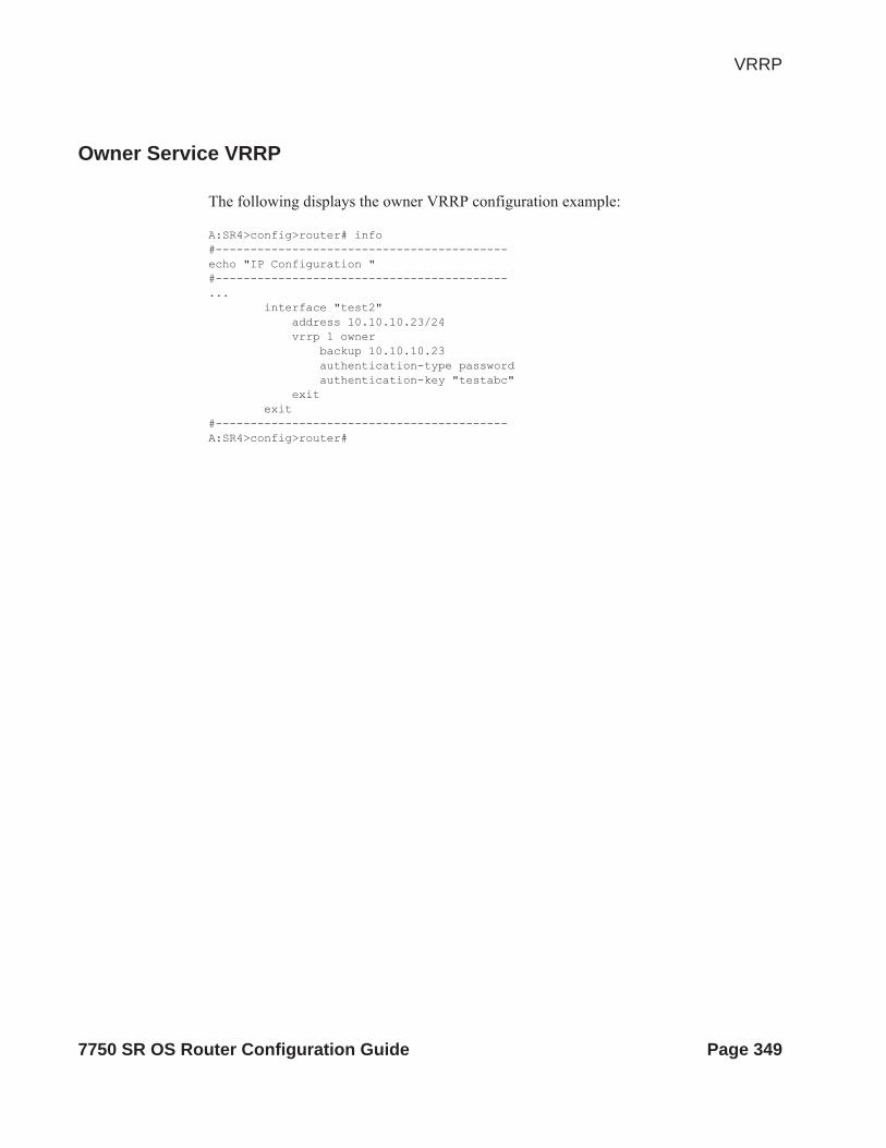
VRRP
Owner Service VRRP
The following displays the owner VRRP configuration example:
A:SR4>config>router# info#------------------------------------------echo "IP Configuration "#------------------------------------------... interface "test2" address 10.10.10.23/24 vrrp 1 owner backup 10.10.10.23 authentication-type password authentication-key "testabc" exit exit#------------------------------------------A:SR4>config>router#
7750 SR OS Router Configuration Guide Page 349

Configuring Router Interface VRRP Parameters
VRRP parameters can be configured on an interface in an interface to provide virtual default router support which allows traffic to be routed without relying on a single router in case of failure.
VRRP can be configured the following ways:
• Router Interface VRRP Non-Owner on page 350
Router Interface VRRP Non-Owner
The following displays a non-owner interface VRRP configuration example:
A:SR2>config># info #------------------------------------------
interface "if-test" address 10.20.30.40/24 secondary 10.10.50.1/24 secondary 10.10.60.1/24 secondary 10.10.70.1/24 vrrp 1 backup 10.10.50.2 backup 10.10.60.2 backup 10.10.70.2 backup 10.20.30.41 ping-reply telnet-reply authentication-type password authentication-key "testabc" exit exit#------------------------------------------A:SR2>config>#
Page 350 7750 SR OS Router Configuration Guide

VRRP
Router Interface VRRP Owner
The following displays router interface owner VRRP configuration example:
A:SR2>config>router# info #------------------------------------------
interface "vrrpowner" address 10.10.10.23/24 vrrp 1 owner backup 10.10.10.23 authentication-type password authentication-key "testabc" exit exit#------------------------------------------A:SR2>config>router#
7750 SR OS Router Configuration Guide Page 351
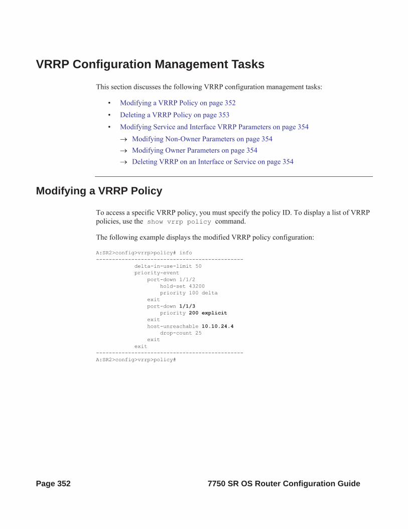
VRRP Configuration Management TasksThis section discusses the following VRRP configuration management tasks:
• Modifying a VRRP Policy on page 352• Deleting a VRRP Policy on page 353• Modifying Service and Interface VRRP Parameters on page 354
Modifying Non-Owner Parameters on page 354 Modifying Owner Parameters on page 354 Deleting VRRP on an Interface or Service on page 354
Modifying a VRRP Policy
To access a specific VRRP policy, you must specify the policy ID. To display a list of VRRP policies, use the show vrrp policy command.
The following example displays the modified VRRP policy configuration:
A:SR2>config>vrrp>policy# info---------------------------------------------- delta-in-use-limit 50 priority-event port-down 1/1/2 hold-set 43200 priority 100 delta exit port-down 1/1/3 priority 200 explicit exit host-unreachable 10.10.24.4 drop-count 25 exit exit----------------------------------------------A:SR2>config>vrrp>policy#
Page 352 7750 SR OS Router Configuration Guide

VRRP
Deleting a VRRP Policy
Policies are only applied to non-owner VRRP instances. A VRRP policy cannot be deleted if it is applied to an interface or to an IES service. Each instance in which the policy is applied must be deleted.
The Applied column in the following example displays whether or not the VRRP policies are applied to an entity.
A:SR2#===============================================================================VRRP Policies===============================================================================Policy Current Current Current Delta Applied Id Priority & Effect Explicit Delta Sum Limit -------------------------------------------------------------------------------1 200 Explicit 200 100 50 Yes15 254 None None 1 No32 100 None None 1 No===============================================================================A:SR2#
7750 SR OS Router Configuration Guide Page 353

Modifying Service and Interface VRRP Parameters
Modifying Non-Owner Parameters
Once a VRRP instance is created as non-owner, it cannot be modified to the owner state. The vrid must be deleted and then recreated with the owner keyword to invoke IP address ownership.
Modifying Owner Parameters
Once a VRRP instance is created as owner, it cannot be modified to the non-owner state. The vrid must be deleted and then recreated without the owner keyword to remove IP address ownership.
Entering the owner keyword is optional when entering the vrid for modification purposes.
Deleting VRRP on an Interface or Service
The vrid does not need to be shutdown to remove the virtual router instance from an interface or service.
Example: config>router#interfaceconfig>router# interface if-testconfig>router>if# shutdownconfig>router>if# exitconfig>router# no interface if-testconfig>router#
The following example displays the command usage to delete a VRRP instance from an interface or IES service:
Example: config>service#ies 10 config>service>ies# interface “test”config>service>ies>if# vrrp 1config>service>ies>if>vrrp# shutdownconfig>service>ies>if>vrrp# exitconfig>service>ies>if# no vrrp 1config>service>ies>if# exit all
Page 354 7750 SR OS Router Configuration Guide

VRRP
VRRP Command Reference
Command Hierarchies
Configuration Commands• VRRP Network Interface Commands on page 356
• Router Interface IPv6 Commands on page 357
• Router Interface IPv6 VRRP Commands on page 358
• VRRP Priority Control Event Policy Commands on page 358
• Show Commands on page 360
• Clear Commands on page 360
7750 SR OS Router Configuration Guide Page 355

VRRP Network Interface Commandsconfig
— router— [no] interface interface-name
— address {ip-address/mask | ip-address netmask} [broadcast all-ones | host-ones]— no address— [no] allow-directed-broadcasts— arp-timeout seconds— no arp-timeout— description description-string— no description— secondary {ip-address/mask | ip-address netmask} [broadcast all-ones | host-
ones] [igp-inhibit]— no secondary {ip-address/mask | ip-address netmask}— [no] shutdown— static-arp ip-address ieee-address— [no] static-arp ip-address— tos-marking-state {trusted | untrusted}— no tos-marking-state— unnumbered [ip-int-name | ip-address]— no unnumbered— vrrp virtual-router-id [owner] *— no vrrp virtual-router-id
— authentication-key [authentication-key | hash-key] [hash | hash2]— no authentication-key— [no] backup ip-address— [no] bfd-enable service-id interface interface-name dst-ip ip-address— [no] bfd-enable interface interface-name dst-ip ip-address— init-delay seconds— no init-delay— mac mac-address— no mac— [no] master-int-inherit— message-interval {[seconds] [milliseconds milliseconds]}— no message-interval— [no] ping-reply— policy policy-id — no policy— [no] preempt— priority priority— no priority— [no] ssh-reply— [no] standby-forwarding— [no] telnet-reply— [no] shutdown— [no] traceroute-reply
* Note that VRRP commands are applicable to router interfaces, IES interfaces and VPRN,The authentication-key, authentication-type, bfd-enable, and ssh-reply commands are applicable only to IPv4 contexts, not IPv6.
Page 356 7750 SR OS Router Configuration Guide

VRRP
Router Interface IPv6 Commandsconfig
— router [router-name]— [no] interface ip-int-name
— [no] ipv6— address ipv6-address/prefix-length [eui-64]— no address ipv6-address/prefix-length — icmp6
— packet-too-big [number seconds]— no packet-too-big— param-problem [number seconds]— no param-problem— redirects [number seconds] — no redirects— time-exceeded[number seconds]— no time-exceeded— unreachables [number seconds] — no unreachables
— link-local-address ipv6-address [preferred]— no link-local-address— [no] local-proxy-nd— neighbor ipv6-address [mac-address]— no neighbor ipv6-address— proxy-nd-policy policy-name [ policy-name...(up to 5 max)]— no proxy-nd-policy
7750 SR OS Router Configuration Guide Page 357
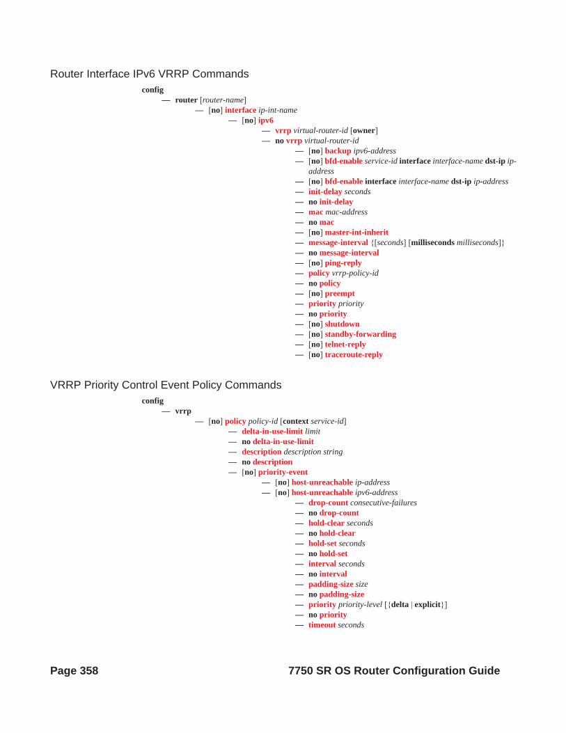
Router Interface IPv6 VRRP Commandsconfig
— router [router-name]— [no] interface ip-int-name
— [no] ipv6— vrrp virtual-router-id [owner]— no vrrp virtual-router-id
— [no] backup ipv6-address— [no] bfd-enable service-id interface interface-name dst-ip ip-
address— [no] bfd-enable interface interface-name dst-ip ip-address— init-delay seconds— no init-delay— mac mac-address— no mac— [no] master-int-inherit— message-interval {[seconds] [milliseconds milliseconds]}— no message-interval— [no] ping-reply— policy vrrp-policy-id— no policy— [no] preempt— priority priority— no priority— [no] shutdown— [no] standby-forwarding— [no] telnet-reply— [no] traceroute-reply
VRRP Priority Control Event Policy Commandsconfig
— vrrp— [no] policy policy-id [context service-id]
— delta-in-use-limit limit— no delta-in-use-limit— description description string— no description— [no] priority-event
— [no] host-unreachable ip-address— [no] host-unreachable ipv6-address
— drop-count consecutive-failures— no drop-count— hold-clear seconds— no hold-clear— hold-set seconds— no hold-set— interval seconds— no interval— padding-size size— no padding-size— priority priority-level [{delta | explicit}]— no priority— timeout seconds
Page 358 7750 SR OS Router Configuration Guide

VRRP
— no timeout— [no] lag-port-down lag-id
— hold-clear seconds— no hold-clear— hold-set seconds— no hold-set— [no] number-down number-of-lag-ports-down
— priority priority-level [delta | explicit]— no priority
— mc-ipsec-non-forwarding tunnel-grp-id— [no] port-down port-id
— hold-clear seconds— no hold-clear— hold-set seconds— no hold-set— priority priority-level [delta | explicit]— no priority
— [no] route-unknown ip-prefix/mask— hold-clear seconds— no hold-clear— hold-set seconds— no hold-set— less-specific [allow-default]— no less-specific— [no] next-hop ip-address— priority priority-level [delta | explicit]— no priority— protocol protocol— no protocol[protocol]— [no] protocol bgp — [no] protocol bgp -vpn— [no] protocol ospf — [no] protocol isis— [no] protocol rip— [no] protocol static
7750 SR OS Router Configuration Guide Page 359

Show Commandsshow
— vrrp— policy [policy-id [event event-type specific-qualifier]]
— router — vrrp
— instance— instance [interface interface-name [vrid virtual-router-id]]— instance interface interface-name vrid virtual-router-id ipv6— statistics
Monitor Commandsmonitor
— router— vrrp
— instance interface interface-name vr-id virtual-router-id [ipv6] [interval sec-onds] [repeat repeat] [absolute | rate]
Clear Commandsclear
— vrrp— statistics
— router— vrrp
— interface ip-int-name [vrid virtual-router-id]— interface ip-int-name vrid virtual-router-id ipv6— statistics interface interface-name [vrid virtual-router-id]— statistics— statistics interface interface-name vrid virtual-router-id ipv6
Debug Commandsdebug
— router— vrrp
— events— events interface ip-int-name [vrid virtual-router-id]— events interface ip-int-name vrid virtual-router-id ipv6— no events— no events interface ip-int-name [vrid virtual-router-id]— no events interface ip-int-name vrid virtual-router-id ipv6— packets— packets interface ip-int-name [vrid virtual-router-id]— packets interface ip-int-name vrid virtual-router-id ipv6— no packets
Page 360 7750 SR OS Router Configuration Guide

VRRP
— no packets interface ip-int-name [vrid virtual-router-id]— no packets interface ip-int-name vrid virtual-router-id ipv6
7750 SR OS Router Configuration Guide Page 361

Page 362 7750 SR OS Router Configuration Guide

VRRP
Configuration Commands
Interface Configuration Commands
authentication-key
Syntax authentication-key [authentication-key | hash-key] [hash | hash2]no authentication-key
Context config>router>if>vrrp
Description This command sets the simple text authentication key used to generate master VRRP advertisement messages and validates VRRP advertisements.
If simple text password authentication is not required, the authenticaton-key command is not required.
The command is configurable in both non-owner and owner vrrp nodal contexts.
The key parameter identifies the simple text password to be used when VRRP Authentication Type 1 is enabled on the virtual router instance. Type 1 uses an eight octet long string that is inserted into all transmitted VRRP advertisement messages and is compared against all received VRRP advertisement messages. The authentication data fields are used to transmit the key.
The key string is case sensitive and is left justified in the VRRP advertisement message authentication data fields. The first field contains the first four characters with the first octet (starting with IETF RFC bit position 0) containing the first character. The second field similarly holds the fifth through eighth characters. Any unspecified portion of the authentication data field is padded with a 0 value in the corresponding octet.
If the command is re-executed with a different password key defined, the new key is used ediately.
The authentication-key command can be executed at anytime.
To change the current in-use password key on multiple virtual router instances:
1. Identify the current master.
2. Shutdown the virtual router instance on all backups.
3. Execute the authentication-key command on the master to change the password key.
4. Execute the authentication-key command and no shutdown command on each backup.
The no form of the command reverts to the default value.
Default no authentication-key — The authentication key value is the null string.
Parameters authentication-key — The authentication key. Allowed values are any string up to 8 characters long composed of printable, 7-bit ASCII characters. If the string contains special characters (#, $, spaces, etc.), the entire string must be enclosed within double quotes.
7750 SR OS Router Configuration Guide Page 363

hash-key — The hash key. The key can be any combination of ASCII characters up to 22 (hash-key1) or 121 (hash-key2) characters in length (encrypted). If spaces are used in the string, enclose the entire string in quotation marks (“ ”).
This is useful when a user must configure the parameter, but for security purposes, the actual unencrypted key value is not provided.
hash — Specifies the key is entered in an encrypted form. If the hash parameter is not used, the key is assumed to be in a non-encrypted, clear text form. For security, all keys are stored in encrypted form in the configuration file with the hash parameter specified.
hash2 — Specifies the key is entered in a more complex encrypted form. If the hash2 parameter is not used, the less encrypted hash form is assumed.
backup
Syntax [no] backup ip-address
Context config>router>if>vrrp
Description This command associates router IP addresses with the parental IP interface IP addresses.
The backup command has two distinct functions when used in an owner or a non-owner context of the virtual router instance.
Non-owner virtual router instances actually create a routable IP interface address that is operationally dependent on the virtual router instance mode (master or backup). The backup command in owner virtual router instances does not create a routable IP interface address; it simply defines the existing parental IP interface IP addresses that are advertised by the virtual router instance.
For owner virtual router instances, the backup command defines the IP addresses that are advertised within VRRP advertisement messages. This communicates the IP addresses that the master is representing to backup virtual routers receiving the messages. Advertising a correct list is important. The specified ip-addr must be equal to one of the existing parental IP interface IP addresses (primary or secondary) or the backup command will fail.
For non-owner virtual router instances, the backup command actually creates an IP interface IP address used for routing IP packets and communicating with the system when the access commands are defined (ping-reply, telnet-reply, and ssh-reply). The specified ip-addr must be an IP address that is within one of the parental IP interface local subnets created with the address or secondary commands. If a local subnet does not exist that includes the specified ip-addr or if ip-addr is the same IP address as the parental IP interface IP address, the backup command will fail.
The new interface IP address created with the backup command assumes the mask and parameters of the corresponding parent IP interface IP address. The ip-addr is only active when the virtual router instance is operating in the master state. When not operating as master, the virtual router instance acts as if it is operationally down. It will not respond to ARP requests to ip-addr, nor will it route packets received with its vrid derived source MAC address. A non-master virtual router instance always silently discards packets destined to ip-addr. A single virtual router instance may only have a single virtual router IP address from a given parental local subnet. Multiple virtual router instances can define a virtual router IP address from the same local subnet as long as each is a different IP address.
Page 364 7750 SR OS Router Configuration Guide

VRRP
In IPv4, up to sixteen backup ip-addr commands can be executed within the same virtual router instance. Executing backup multiple times with the same ip-addr results in no operation performed and no error generated. At least one successful backup ip-addr command must be executed before the virtual router instance can enter the operational state.
When operating as (non-owner) master, the default functionality associated with ip-addr is ARP response to ARP requests to ip-addr, routing of packets destined to the virtual router instance source MAC address and silently discarding packets destined to ip-addr. Enabling the non-owner-access parameters selectively allows ping, Telnet and SSH connectivity to ip-addr when the virtual router instance is operating as master.
The no form of the command removes the specified virtual router IP address from the virtual router instance. For non-owner virtual router instances, this causes all routing and local access associated with the ip-addr to cease. For owner virtual router instances, the no backup command only removes ip-addr from the list of advertised IP addresses. If the last ip-addr is removed from the virtual router instance, the virtual router instance will enter the operationally down state
Special Cases Assigning the Virtual Router ID IP Address — Once the vrid is created on the parent IP interface, IP addresses need to be assigned to the virtual router instance. If the vrid was created with the keyword owner, the virtual router instance IP addresses must have one or more of the parent IP interface defined IP addresses (primary and secondary). For non-owner virtual router instances, the virtual router IP addresses each must be within one of the parental IP interface IP address defined local subnets. For both owner and non-owner virtual router instances, the virtual router IP addresses must be explicitly defined using the backup ip-addr command.
Virtual Router Instance IP Address Assignment Conditions — The RFC does not specify that the assigned IP addresses to the virtual router instance must be in the same subnet as the parent IP interface primary IP address or secondary IP addresses. The only requirement is that all virtual routers participating in the same virtual router instance have the same virtual router IP addresses assigned. To avoid confusion, the assigned virtual router IP addresses must be in a local subnet of one of the parent IP interfaces IP addresses. For owner virtual router instances the assigned virtual router IP address must be the same as one of the parental IP interface primary or secondary IP addresses.
The following rules apply when adding, changing, or removing parental and virtual router IP addresses:
Owner Virtual Router IP Address Parental Association — When an IP address is assigned to an owner virtual router instance, it must be associated with one of the parental IP interface-assigned IP addresses. The virtual router IP address must be equal to the primary or one of the secondary IP addresses within the parental IP interface.
Example - Owner Virtual Router Instance
Parent IP addresses: 10.10.10.10/2411.11.11.11/24
Virtual router IP addresses: 10.10.10.11 Invalid (not equal to parent IP address)
10.10.10.10 Associated (same as parent IP address 10.10.10.10)
10.10.11.11 Invalid (not equal to parent IP address)
7750 SR OS Router Configuration Guide Page 365

Non-Owner Virtual Router IP Address Parental Association — When an IP address is assigned to a non-owner virtual router instance, it must be associated with one of the parental IP interface assigned IP addresses. The virtual router IP address must be a valid IP address within one of the parental IP interfaces local subnet. Local subnets are created by the primary or secondary IP addresses in conjunction with the IP addresses mask. If the defined virtual router IP address is equal to the associated subnet’s broadcast address, it is invalid. Virtual router IP addresses for non-owner virtual router instances that are equal to a parental IP interface IP address are also invalid.
The same virtual router IP address may not be assigned to two separate virtual router instances. If the virtual router IP address already exists on another virtual router instance, the virtual router IP address assignment will fail.
Example - Non-Owner Virtual Router Instance
Virtual Router IP Address Assignment without Parent IP Address — When assigning an IP address to a virtual router instance, an associated IP address (see Owner Virtual Router IP Address Parental Association and Non-Owner Virtual Router IP Address Parental Association) on the parental IP interface must already exist. If an associated IP address on the parental IP interface is not configured, the virtual router IP address assignment fails.
Parent Primary IP Address Changed — When a virtual router IP address is set and the associated parent IP interface IP address is changed, the new parent IP interface IP address is evaluated to ensure it meets the association rules defined in Owner Virtual Router IP Address Parental Association or Non-Owner Virtual Router IP Address Parental Association. If the association check fails, the parental IP address change is not allowed. If the parental IP address change fails, the previously configured IP address definition remains in effect.
Only the primary parent IP address can be changed. Secondary addresses must be removed before the new IP address can be added. Parent Primary or Secondary IP Address Removal explains IP address removal conditions.
Parent Primary or Secondary IP Address Removal — When a virtual router IP address is successfully set, but removing the associated parent IP interface IP address is attempted and fails. All virtual router IP addresses associated with the parental IP interface IP address must be deleted prior
11.11.11.254 Invalid (not equal to parent IP address)
11.11.11.255 Invalid (not equal to parent IP address)
Parent IP addresses: 10.10.10.10/2411.11.11.11/24
Virtual router IP addresses: 10.10.10.11 Associated with 10.10.10.10 (in subnet)
10.10.10.10 Invalid (same as parent IP address)
10.10.11.11 Invalid (outside of all Parent IP subnets)
11.11.11.254 Associated with 11.11.11.11 (in subnet)
11.11.11.255 Invalid (broadcast address of 11.11.11.11/24)
Page 366 7750 SR OS Router Configuration Guide

VRRP
to removing the parental IP address. This includes virtual router IP address associations from multiple virtual router instances on the IP interface.
Default no backup — No virtual router IP address is assigned.
Parameters ip-address — The virtual router IP address expressed in dotted decimal notation. The IP virtual router IP address must be in the same subnet of the parental IP interface IP address or equal to one of the primary or secondary IP addresses for owner virtual router instances.
Values 1.0.0.1 - 223.255.255.254
backup
Syntax config>router>if>ipv6>vrrp
Description This command associates router IPv6 addresses with the parental IP interface IP addresses.
The backup command has two distinct functions when used in an owner or a non-owner context of the virtual router instance.
Non-owner virtual router instances actually create a routable IP interface address that is operationally dependent on the virtual router instance mode (master or backup). The backup command in owner virtual router instances does not create a routable IP interface address; it simply defines the existing parental IP interface IP addresses that are advertised by the virtual router instance.
For owner virtual router instances, the backup command defines the IP addresses that are advertised within VRRP advertisement messages. This communicates the IP addresses that the master is representing to backup virtual routers receiving the messages. Advertising a correct list is important. The specified ipv6-addr must be equal to one of the existing parental IP interface IP addresses (link-local or global) or the backup command will fail.
For non-owner virtual router instances, the backup command actually creates an IP interface IP address used for routing IP packets and communicating with the system when the access commands are defined (ping-reply, telnet-reply, and ssh-reply). The specified ipv6-addr must be an IP address that is within one of the parental IP interface local subnets created with the link-local-address or address commands. If a local subnet does not exist that includes the specified ipv6-addr or if ipv6-addr is the same IP address as the parental IP interface IP address, the backup command will fail.
The new interface IP address created with the backup command assumes the mask and parameters of the corresponding parent IP interface IP address. The ipv6-addr is only active when the virtual router instance is operating in the master state. For IPv6 VRRP, the parental interface's IP address that is in the same subnet as the backup address must be manually-configured, non EUI-64 and configured to be in the preferred state.
When not operating as master, the virtual router instance acts as if it is operationally down. It will not respond to ARP requests to ipv6-addr, nor will it route packets received with its vrid derived source MAC address. A non-master virtual router instance always silently discards packets destined to ipv6-addr. A single virtual router instance may only have a single virtual router IP address from a given parental local subnet. Multiple virtual router instances can define a virtual router IP address from the same local subnet as long as each is a different IP address.
7750 SR OS Router Configuration Guide Page 367

Executing backup multiple times with the same ipv6-addr results in no operation performed and no error generated. At least one successful backup ipv6-addr command must be executed before the virtual router instance can enter the operational state.
When operating as (non-owner) master, the default functionality associated with ipv6-addr is ARP response to ARP requests to ip-addr, routing of packets destined to the virtual router instance source MAC address and silently discarding packets destined to ipv6-addr. An IPv6 virtual router instance can enter the operational state only if one of the configured backup address is a link-local address and the router advertisement of the interface is configured to use the virtual MAC address. Enabling the non-owner-access parameters selectively allows ping, Telnet and traceroute connectivity to ipv6-addr when the virtual router instance is operating as master.
The no form of the command removes the specified virtual router IP address from the virtual router instance. For non-owner virtual router instances, this causes all routing and local access associated with the ipv6-addr to cease. For owner virtual router instances, the no backup command only removes ipv6-addr from the list of advertised IP addresses. If the last ipv6-addr or the link-local address is removed from the virtual router instance, the virtual router instance will enter the operationally down state
Special Cases Assigning the Virtual Router ID Address — Once the vrid is created on the parent IP interface, IP addresses need to be assigned to the virtual router instance. If the vrid was created with the keyword owner, the virtual router instance IP addresses must have one or more of the parent IP interface defined IP addresses. For non-owner virtual router instances, the virtual router IP addresses each must be within one of the parental IP interface IP address defined local subnets. For both owner and non-owner virtual router instances, the virtual router IP addresses must be explicitly defined using the backup ipv6-addr command.
The following rules apply when adding, changing, or removing parental and virtual router IP addresses:
Owner Virtual Router IP Address Parental Association — When an IP address is assigned to an owner virtual router instance, it must be associated with one of the parental IP interface-assigned IP addresses.
Example - Owner Virtual Router Instance
Non-Owner Virtual Router IP Address Parental Association — When an IP address is assigned to a non-owner virtual router instance, it must be associated with one of the parental IP interface assigned IP addresses. The virtual router IP address must be a valid IP address within one of
Parent IP addresses: 10.10.10.10/2411.11.11.11/24
Virtual router IP addresses: 10.10.10.11 Invalid (not equal to parent IP address)
10.10.10.10 Associated (same as parent IP address 10.10.10.10)
10.10.11.11 Invalid (not equal to parent IP address)
11.11.11.254 Invalid (not equal to parent IP address)
11.11.11.255 Invalid (not equal to parent IP address)
Page 368 7750 SR OS Router Configuration Guide

VRRP
the parental IP interfaces local subnet. Local subnets are created by the link-local or global IP addresses in conjunction with the IP addresses mask. If the defined virtual router IP address is equal to the associated subnet’s broadcast address, it is invalid. Virtual router IP addresses for non-owner virtual router instances that are equal to a parental IP interface IP address are also invalid.
The same virtual router IP address may not be assigned to two separate virtual router instances. If the virtual router IP address already exists on another virtual router instance, the virtual router IP address assignment will fail.
One exception to this rule is for the IPv6 link-local address that is configured as a backup address. The same link-local address can be configured in all virtual routers that use the same vrid.
Example - Non-Owner Virtual Router Instance
Virtual Router IP Address Assignment without Parent IP Address — When assigning an IP address to a virtual router instance, an associated IP address (see Owner Virtual Router IP Address Parental Association and Non-Owner Virtual Router IP Address Parental Association) on the parental IP interface must already exist. If an associated IP address on the parental IP interface is not configured, the virtual router IP address assignment fails.
Virtual Router IPv6 Address Assignment — An IPv6 backup address requires that the parental IP address that is in the same subnet as the backup address must be manually configured, non-EUI-64 and configured to be in the preferred state.
Default no backup — No virtual router IP address is assigned.
Parameters ipv6-address — The virtual router IP address expressed in dotted decimal notation. The IP virtual router IP address must be in the same subnet of the parental IP interface IP address or equal to one of the the parent interface addresses for owner virtual router instances.
Values ipv6-address x:x:x:x:x:x:x:x (eight 16-bit pieces) x:x:x:x:x:x::d.d.d.dx: [0..FFFF]Hd: [0..255]D
Parent IP addresses: 10.10.10.10/2411.11.11.11/24
Virtual router IPv6 addresses: 10.10.10.11 Associated with 10.10.10.10 (in subnet)
10.10.10.10 Invalid (same as parent IP address)
10.10.11.11 Invalid (outside of all Parent IP subnets)
11.11.11.254 Associated with 11.11.11.11 (in subnet)
11.11.11.255 Invalid (broadcast address of 11.11.11.11/24)
7750 SR OS Router Configuration Guide Page 369

bfd-enable
Syntax [no] bfd-enable [service-id] interface interface-name dst-ip ip-address[no] bfd-enable interface interface-name dst-ip ip-address
Context config>router>if>vrrpconfig>router>if>ipv6>vrrp
Description This commands assigns a bi-directional forwarding (BFD) session providing heart-beat mechanism for the given VRRP/SRRP instance. There can be only one BFD session assigned to any given VRRP/SRRP instance, but there can be multiple SRRP/VRRP sessions using the same BFD session.
BFD control the state of the associated interface. By enabling BFD on a given protocol interface, the state of the protocol interface is tied to the state of the BFD session between the local node and the remote node. The parameters used for the BFD are set by the BFD command under the IP interface. The specified interface may not be configured with BFD; when it is, the virtual router will then initiate the BFD session.
The no form of this command removes BFD from the configuration.
Default none
Parameters service-id — Specifies the service ID of the interface running BFD.
Values service-id: 1 — 2147483647svc-name: 64 characters maximum
interface interface-name — Specifies the name of the interface running BFD. The specified interface may not yet be configured with BFD. However, when it is, this virtual router will then initiate the BFD session.
dst-ip ip-address — Specifies the destination address to be used for the BFD session.
init-delay
Syntax init-delay secondsno init-delay
Context config>router>if>vrrpconfig>router>if>ipv6>vrrp
Description This command configures a VRRP initialization delay timer.
Parameters seconds — Specifies the initialization delay timer for VRRP, in seconds.
Values 1 — 65535
Page 370 7750 SR OS Router Configuration Guide

VRRP
mac
Syntax mac mac-addressno mac
Context config>router>if>vrrpconfig>router>if>ipv6>vrrp
Description This command sets an explicit MAC address used by the virtual router instance overriding the VRRP default derived from the VRID.
Changing the default MAC address is useful when an existing HSRP or other non-VRRP default MAC is in use by the IP hosts using the virtual router IP address. Many hosts do not monitor unessential ARPs and continue to use the cached non-VRRP MAC address after the virtual router becomes master of the host’s gateway address.
The mac command sets the MAC address used in ARP responses when the virtual router instance is master. Routing of IP packets with mac-address as the destination MAC is also enabled. The mac setting must be the same for all virtual routers participating as a virtual router or indeterminate connectivity by the attached IP hosts will result. All VRRP advertisement messages are transmitted with mac-address as the source MAC.
The command can be configured in both non-owner and owner vrrp nodal contexts.
The mac command can be executed at any time and takes effect ediately. When the virtual router MAC on a master virtual router instance changes, a gratuitous ARP is ediately sent with a VRRP advertisement message. If the virtual router instance is disabled or operating as backup, the gratuitous ARP and VRRP advertisement message is not sent.
The no form of the command restores the default VRRP MAC address to the virtual router instance.
Default no mac — The virtual router instance uses the default VRRP MAC address derived from the VRID.
Parameters mac-address — The 48-bit MAC address for the virtual router instance in the form aa:bb:cc:dd:ee:ff or aa-bb-cc-dd-ee-ff where aa, bb, cc, dd, ee and ff are hexadecimal numbers. Allowed values are any non-broadcast, non-multicast MAC, and non-IEEE reserved MAC addresses.
master-int-inherit
Syntax [no] master-int-inherit
Context config>router>if>vrrpconfig>router>if>ipv6>vrrp
Description This command enables the virtual router instance to inherit the master VRRP router’s advertisement interval timer which is used by backup routers to calculate the master down timer.
The master-int-inherit command is only available in the non-owner nodal context and is used to allow the current virtual router instance master to dictate the master down timer for all backup virtual routers. The master-int-inherit command has no effect when the virtual router instance is operating as master.
7750 SR OS Router Configuration Guide Page 371

If master-int-inherit is not enabled, the locally configured message-interval must match the master’s VRRP advertisement message advertisement interval field value or the message is discarded.
The no form of the command restores the default operating condition which requires the locally configured message-interval to match the received VRRP advertisement message advertisement interval field value.
Default no master-int-inherit — The virtual router instance does not inherit the master VRRP router’s advertisement interval timer and uses the locally configured message interval.
message-interval
Syntax message-interval {[seconds] [milliseconds milliseconds]}no message-interval
Context config>router>if>vrrpconfig>router>if>ipv6>vrrp
Description This command configures the administrative advertisement message timer used by the master virtual router instance to send VRRP advertisement messages and to derive the master down timer as backup.
For an owner virtual router instance, the administrative advertisement timer directly sets the operational advertisement timer and indirectly sets the master down timer for the virtual router instance.
Non-owner virtual router instances usage of the message-interval setting is dependent on the state of the virtual router (master or backup) and the state of the master-int-inherit parameter.
• When a non-owner is operating as master for the virtual router, the configured message-interval is used as the operational advertisement timer similar to an owner virtual router instance. The master-int-inherit command has no effect when operating as master.
• When a non-owner is in the backup state with master-int-inherit disabled, the configured mes-sage-interval value is used to match the incoming VRRP advertisement message advertisement interval field. If the locally configured message interval does not match the advertisement inter-val field, the VRRP advertisement is discarded.
• When a non-owner is in the backup state with master-int-inherit enabled, the configured mes-sage-interval is ignored. The master down timer is indirectly derived from the incoming VRRP advertisement message advertisement interval field value.
VRRP advertisements messages that are fragmented, contain IP options (IPv4), or contain extension headers (IPv6) require a longer message interval to be configured.
The in-use value of the message interval is used to derive the master down timer to be used when the virtual router is operating in backup mode based on the following formula:
(3x (in-use message interval) + skew time)
The skew time portion is used to slow down virtual routers with relatively low priority values when competing in the master election process.
The command is available in both non-owner and owner vrrp nodal contexts.
Page 372 7750 SR OS Router Configuration Guide

VRRP
By default, a message-interval of 1 second is used.
The no form of the command reverts to the default value.
Default 1 — Advertisement timer set to 1 second
Parameters seconds — The number of seconds that will transpire before the advertisement timer expires expressed as a decimal integer.
Values IPv4: 1 — 255IPv6: 1 — 40
milliseconds milliseconds — Specifies the time interval, in milliseconds, between sending advertisement messages. This parameter is not supported on the 7750 SR-1 or 7450 ESS-1 chassis.
Values 100 — 900IPv6: 10 — 990
policy
Syntax policy policy-id no policy
Context config>router>if>vrrpconfig>router>if>ipv6>vrrp
Description This command adds a VRRP priority control policy association with the virtual router instance.
To further augment the virtual router instance base priority, VRRP priority control policies can be used to override or adjust the base priority value depending on events or conditions within the chassis.
The policy can be associated with more than one virtual router instance. The priority events within the policy either override or diminish the base priority set with the priority command dynamically affecting the in-use priority. As priority events clear in the policy, the in-use priority can eventually be restored to the base priority value.
The policy command is only available in the non-owner vrrp nodal context. The priority of owner virtual router instances is permanently set to 255 and cannot be changed by VRRP priority control policies. For non-owner virtual router instances, if the policy command is not executed, the base priority is used as the in-use priority.
The no form of the command removes existing VRRP priority control policy associations from the virtual router instance. All associations must be removed prior to deleting the policy from the system.
Default no policy — No VRRP priority control policy is associated with the virtual router instance.
Parameters policy-id — The policy ID of the VRRP priority control expressed as a decimal integer. The vrrp-policy-id must already exist for the command to function.
Values 1 — 9999
7750 SR OS Router Configuration Guide Page 373

preempt
Syntax [no] preempt
Context config>router>if>vrrpconfig>router>if>ipv6>vrrp
Description This command enables the overriding of an existing VRRP master if the virtual router’s in-use priority is higher than the current master.
The priority of the non-owner virtual router instance, the preempt mode allows the best available virtual router to force itself as the master over other available virtual routers.
When preempt is enabled, the virtual router instance overrides any non-owner master with an in-use message priority value less than the virtual router instance in-use priority value. If preempt is disabled, the virtual router only becomes master if the master down timer expires before a VRRP advertisement message is received from another virtual router.
Enabling preempt mode improves the effectiveness of the base priority and the VRRP priority control policy mechanisms on the virtual router instance. If the virtual router cannot preempt an existing non-owner master, the affect of the dynamic changing of the in-use priority is diminished.
The preempt command is only available in the non-owner vrrp nodal context. The owner may not be preempted because the priority of non-owners can never be higher than the owner. The owner always preempts all other virtual routers when it is available.
Non-owner virtual router instances only preempt when preempt is set and the current master has an in-use message priority value less than the virtual router instances in-use priority.
A master non-owner virtual router only allows itself to be preempted when the incoming VRRP advertisement message priority field value is one of the following:
• Greater than the virtual router in-use priority value.
• Equal to the in-use priority value and the source IP address (primary IP address) is greater than the virtual router instance primary IP address.
By default, preempt mode is enabled on the virtual router instance.
The no form of the command disables preempt mode and prevents the non-owner virtual router instance from preempting another, less desirable virtual router.
Default preempt — The preempt mode enabled on the virtual router instance where it will preempt a VRRP master with a lower priority.
priority
Syntax priority base-priorityno priority
Context config>router>if>vrrpconfig>router>if>ipv6>vrrp
Description This command configures the base router priority for the virtual router instance used in the master election process.
Page 374 7750 SR OS Router Configuration Guide

VRRP
The priority is the most important parameter set on a non-owner virtual router instance. The priority defines a virtual router’s selection order in the master election process. Together, the priority value and the preempt mode allow the virtual router with the best priority to become the master virtual router.
The base-priority is used to derive the in-use priority of the virtual router instance as modified by any optional VRRP priority control policy. VRRP priority control policies can be used to either override or adjust the base priority value depending on events or conditions within the chassis.
The priority command is only available in the non-owner vrrp nodal context. The priority of owner virtual router instances is permanently set to 255 and cannot be changed.
For non-owner virtual router instances, the default base priority value is 100.
The no form of the command reverts to the default value.
Default 100
Parameters base-priority — The base priority used by the virtual router instance expressed as a decimal integer. If no VRRP priority control policy is defined, the base-priority is the in-use priority for the virtual router instance.
Values 1 — 254
ping-reply
Syntax [no] ping-reply
Context config>router>if>vrrpconfig>router>if>ipv6>vrrp
Description This command enables the non-owner master to reply to ICMP echo requests directed at the vritual router instances IP addresses.
Non-owner virtual router instances are limited by the VRRP specifications to responding to ARP requests destined to the virtual router IP addresses and routing IP packets not addressed to the virtual router IP addresses. Many network administrators find this limitation frustrating when troubleshooting VRRP connectivity issues.
7750 SR OS allows this access limitation to be selectively lifted for certain applications. Ping, Telnet and SSH can be individually enabled or disabled on a per-virtual-router-instance basis.
The ping-reply command enables the non-owner master to reply to ICMP echo requests directed at the virtual router instances IP addresses. The Ping request can be received on any routed interface. Ping must not have been disabled at the management security level (either on the parental IP interface or based on the Ping source host address).
When ping-reply is not enabled, ICMP echo requests to non-owner master virtual IP addresses are silently discarded.
Non-owner backup virtual routers never respond to ICMP echo requests regardless of the ping-reply setting.
The ping-reply command is only available in non-owner vrrp nodal context.
By default, ICMP echo requests to the virtual router instance IP addresses are silently discarded.
7750 SR OS Router Configuration Guide Page 375

The no form of the command configures discarding all ICMP echo request messages destined to the non-owner virtual router instance IP addresses.
Default no ping-reply — ICMP echo requests to the virtual router instance IP addresses are discarded.
shutdown
Syntax [no] shutdown
Context config>router>if>vrrpconfig>router>if>ipv6>vrrp
Description This command administratively disables an entity. When disabled, an entity does not change, reset, or remove any configuration settings or statistics.
The operational state of the entity is disabled as well as the operational state of any entities contained within. Many objects must be shut down before they may be deleted.
The no form of this command administratively enables an entity.
Special Cases Non-Owner Virtual Router — Non-owner virtual router instances can be administratively shutdown. This allows the termination of VRRP participation in the virtual router and stops all routing and other access capabilities with regards to the virtual router IP addresses. Shutting down the virtual router instance provides a mechanism to maintain the virtual routers without causing false backup/master state changes.
If the shutdown command is executed, no VRRP advertisement messages are generated and all received VRRP advertisement messages are silently discarded with no processing.
By default, virtual router instances are created in the no shutdown state.
Whenever the administrative state of a virtual router instance transitions, a log message is generated.
Whenever the operational state of a virtual router instance transitions, a log message is generated.
Owner Virtual Router — An owner virtual router context does not have a shutdown command. To administratively disable an owner virtual router instance, use the shutdown command within the parent IP interface node which administratively downs the IP interface.
ssh-reply
Syntax [no] ssh-reply
Context config>router>if>vrrp
Description This command enables the non-owner master to reply to SSH requests directed at the virtual router instance IP addresses. This command is only applicable to IPv4.
Non-owner virtual router instances are limited by the VRRP specifications to responding to ARP requests destined to the virtual router IP addresses and routing IP packets not addressed to the virtual router IP addresses.
Page 376 7750 SR OS Router Configuration Guide

VRRP
This limitation can be disregarded for certain applications. Ping, Telnet and SSH can be individually enabled or disabled on a per-virtual-router-instance basis.
The ssh-reply command enables the non-owner master to reply to SSH requests directed at the virtual router instances IP addresses. The SSH request can be received on any routed interface. SSH must not have been disabled at the management security level (either on the parental IP interface or based on the SSH source host address). Proper login and CLI command authentication is still enforced.
When ssh-reply is not enabled, SSH requests to non-owner master virtual IP addresses are silently discarded.
Non-owner backup virtual routers never respond to SSH requests regardless of the ssh-reply setting.
The ssh-reply command is only available in non-owner vrrp nodal context.
By default, SSH requests to the virtual router instance IP addresses are silently discarded.
The no form of the command discards all SSH request messages destined to the non-owner virtual router instance IP addresses.
Default no ssh-reply — SSH requests to the virtual router instance IP addresses are discarded.
standby-forwarding
Syntax [no] standby-forwarding
Context config>router>if>vrrpconfig>router>if>ipv6>vrrp
Description This command specifies whether this VRRP instance allows forwarding packets to a standby router. When disabled, a standby router should not forward traffic sent to virtual router's MAC address. However, the standby router should forward traffic sent to the standby router’s real MAC address. When enabled, a standby router should forward all traffic.
telnet-reply
Syntax [no] telnet-reply
Context config>router>if>vrrpconfig>router>if>ipv6>vrrp
Description This command enables the non-owner master to reply to TCP port 23 Telnet requests directed at the virtual router instances’ IP addresses.
Non-owner virtual router instances are limited by the VRRP specifications to responding to ARP requests destined to the virtual router IP addresses and routing IP packets not addressed to the virtual router IP addresses. Many network administrators find this limitation frustrating when troubleshooting VRRP connectivity issues.
This limitation can be disregarded for certain applications. Ping, SSH and Telnet can each be individually enabled or disabled on a per-virtual-router-instance basis.
7750 SR OS Router Configuration Guide Page 377

The telnet-reply command enables the non-owner master to reply to Telnet requests directed at the virtual router instances’ IP addresses. The Telnet request can be received on any routed interface. Telnet must not have been disabled at the management security level (either on the parental IP interface or based on the Telnet source host address). Proper login and CLI command authentication is still enforced.
When telnet-reply is not enabled, Telnet requests to non-owner master virtual IP addresses are silently discarded.
Non-owner backup virtual routers never respond to Telnet requests regardless of the telnet-reply setting.
The telnet-reply command is only available in non-owner vrrp nodal context.
By default, Telnet requests to the virtual router instance IP addresses will be silently discarded.
The no form of the command configures discarding all Telnet request messages destined to the non-owner virtual router instance IP addresses.
Default no telnet-reply — Telnet requests to the virtual router instance IP addresses are discarded.
traceroute-reply
Syntax [no] traceroute-reply
Context config>router>if>vrrpconfig>router>if>ipv6>vrrp
Description This command is valid only if the VRRP virtual router instance associated with this entry is a non-owner.
When this command is enabled, a non-owner master can reply to traceroute requests directed to the virtual router instance IP addresses.
A non-owner backup virtual router never responds to such traceroute requests regardless of the trace-route-reply status.
Default no traceroute-reply
vrrp
Syntax vrrp vrid [owner]no vrrp vrid
Context config>router>interface ip-int-nameconfig>router>if>ipv6
Description This command creates the context to configure a VRRP virtual router instance. A virtual router is defined by its virtual router identifier (VRID) and a set of IP addresses.
The optional owner keyword indicates that the owner controls the IP address of the virtual router and is responsible for forwarding packets sent to this IP address. The owner assumes the role of the master virtual router.
Page 378 7750 SR OS Router Configuration Guide

VRRP
All other virtual router instances participating in this message domain must have the same vrid configured and cannot be configured as owner. Once created, the owner keyword is optional when entering the vrid for configuration purposes.
A vrid is internally associated with the IP interface. This allows the vrid to be used on multiple IP interfaces while representing different virtual router instances.
For IPv4, up to four vrrp vrid nodes can be configured on a router interface. Each virtual router instance can manage up to 16 backup IP addresses. For IPv6, only one virtual router ID can be configured on a router interface.
The no form of the command removes the specified vrid from the IP interface. This terminates VRRP participation and deletes all references to the vrid in conjunction with the IP interface. The vrid does not need to be shutdown to remove the virtual router instance.
Special Cases Virtual Router Instance Owner IP Address Conditions — It is possible for the virtual router instance owner to be created prior to assigning the parent IP interface primary or secondary IP addresses. When this is the case, the virtual router instance is not associated with an IP address. The operational state of the virtual router instance is down.
VRRP Owner Command Exclusions — By specifying the VRRP vrid as owner, The following commands are no longer available:
• vrrp priority — The virtual router instance owner is hard-coded with a priority value of 255 and cannot be changed.
• vrrp master-int-inherit — Owner virtual router instances do not accept VRRP advertisement messages; the advertisement interval field is not evaluated and cannot be inherited.
• ping-reply, telnet-reply and ssh-reply — The owner virtual router instance always allows Ping, Telnet and SSH if the management and security parameters are configured to accept them on the parent IP interface.
• vrrp shutdown — The owner virtual router instance cannot be shutdown in the vrrp node. If this was allowed, VRRP messages would not be sent, but the parent IP interface address would continue to respond to ARPs and forward IP packets. Another virtual router instance may detect the missing master due to the termination of VRRP advertisement messages and become master. This would cause two routers responding to ARP requests for the same IP addresses. To shut-down the owner virtual router instance, use the shutdown command in the parent IP interface context. This will prevent VRRP participation, IP ARP reply and IP forwarding. To continue par-ent IP interface ARP reply and forwarding without VRRP participation, remove the vrrp vrid instance.
• traceroute-reply
Default no vrrp — No VRRP virtual router instance is associated with the IP interface.
Parameters vrid — The virtual router ID for the IP interface expressed as a decimal integer.
Values 1 — 255
owner — Identifies this virtual router instance as owning the virtual router IP addresses. If the owner keyword is not specified at the time of vrid creation, the vrrp backup commands must be specified to define the virtual router IP addresses. The owner keyword is not required when entering the vrid for editing purposes. Once created as owner, a vrid on an IP interface cannot
7750 SR OS Router Configuration Guide Page 379

have the owner parameter removed. The vrid must be deleted and than recreated without the owner keyword to remove ownership.
Page 380 7750 SR OS Router Configuration Guide

VRRP
Priority Policy Commands
delta-in-use-limit
Syntax delta-in-use-limit in-use-priority-limitno delta-in-use-limit
Context config>vrrp>policy vrrp-policy-id
Description This command sets a lower limit on the virtual router in-use priority that can be derived from the delta priority control events.
Each vrrp-priority-id places limits on the delta priority control events to define the in-use priority of the virtual router instance. Setting this limit prevents the sum of the delta priority events from lowering the in-use priority value of the associated virtual router instances below the configured value.
The limit has no effect on explicit priority control events. Explicit priority control events are controlled by setting the in-use priority to any value between 1 and 254.
Only non-owner virtual router instances can be associated with VRRP priority control policies and their priority control events.
Once the total sum of all delta events is calculated and subtracted from the base priority of the virtual router instance, the result is compared to the delta-in-use-limit value. If the result is less than the limit, the delta-in-use-limit value is used as the virtual router in-use priority value. If an explicit priority control event overrides the delta priority control events, the delta-in-use-limit has no effect.
Setting the limit to a higher value than the default of 1 limits the effect of the delta priority control events on the virtual router instance base priority value. This allows for multiple priority control events while minimizing the overall effect on the in-use priority.
Changing the in-use-priority-limit causes an ediate re-evaluation of the in-use priority values for all virtual router instances associated with this vrrp-policy-id based on the current sum of all active delta control policy events.
The no form of the command reverts to the default value.
Default 1 — The lower limit of 1 for the in-use priority, as modified, by delta priorty control events.
Parameters in-use-priority-limit — The lower limit of the in-use priority base, as modified by priority control policies. The in-use-priority-limit has the same range as the non-owner virtual router instance base-priority parameter. If the result of the total delta priority control events minus the virtual router instances base-priority, is less than the in-use-priority-limit, the in-use-priority-limit value is used as the virtual router instances in-use priority value.
Setting the in-use-priority-limit to a value equal to or larger than the virtual router instance base-priority prevents the delta priority control events from having any effect on the virtual router instance in-use priority value.
Values 1 — 254
7750 SR OS Router Configuration Guide Page 381

description
Syntax description stringno description
Context config>vrrp>policy vrrp-policy-id
Description This command creates a text description stored in the configuration file for a configuration context.
The description command associates a text string with a configuration context to help identify the content in the configuration file.
The no form of the command removes the string from the configuration.
Default none
Parameters string — The description character string. Allowed values are any string up to 80 characters long composed of printable, 7-bit ASCII characters. If the string contains special characters (#, $, spaces, etc.), the entire string must be enclosed within double quotes.
policy
Syntax policy policy-id [context service-id]no policy policy-id
Context config>vrrp
Description This command creates the context to configure a VRRP priority control policy which is used to control the VRRP in-use priority based on priority control events. It is a parental node for the various VRRP priority control policy commands that define the policy parameters and priority event conditions.
The virtual router instance priority command defines the initial or base value to be used by non-owner virtual routers. This value can be modified by assigning a VRRP priority control policy to the virtual router instance. The VRRP priority control policy can override or diminish the base priority setting to establish the actual in-use priority of the virtual router instance.
The policy policy-id command must be created first, before it can be associated with a virtual router instance.
Because VRRP priority control policies define conditions and events that must be maintained, they can be resource intensive. The number of policies is limited to 1000.
The policy-id do not have to be consecutive integers. The range of available policy identifiers is from 1 to 9999.
The no form of the command deletes the specific policy-id from the system. The policy-id must be removed first from all virtual router instances before the no policy command can be issued. If the policy-id is associated with a virtual router instance, the command will fail.
Default none
Page 382 7750 SR OS Router Configuration Guide

VRRP
Parameters vrrp-policy-id — The VRRP priority control ID expressed as a decimal integer that uniquely identifies this policy from any other VRRP priority control policy defined on the system. Up to 1000 policies can be defined.
Values 1 — 9999
context service-id — Specifies the service ID to which this policy applies. A value of zero (0) means that this policy does not apply to a service but applies to the base router instance.
Values 1 — 2147483647
priority-event
Syntax [no] priority-event
Context config>vrrp>policy vrrp-priority-id
Description This command creates the context to configure VRRP priority control events used to define criteria to modify the VRRP in-use priority.
A priority control event specifies an object to monitor and the effect on the in-use priority level for an associated virtual router instance.
Up to 32 priority control events can be configured within the priority-event node.
The no form of the command clears any configured priority events.
7750 SR OS Router Configuration Guide Page 383

Priority Policy Event Commands
hold-clear
Syntax hold-clear secondsno hold-clear
Context config>vrrp>policy>priority-event>port-downconfig>vrrp>policy>priority-event>lag-port-downconfig>vrrp>policy>priority-event>route-unknown
Description This command configures the hold clear time for the event. The seconds parameter specifies the hold-clear time, the amount of time in seconds by which the effect of a cleared event on the associated virtual router instance is delayed.
The hold-clear time is used to prevent black hole conditions when a virtual router instance advertises itself as a master before other conditions associated with the cleared event have had a chance to enter a forwarding state.
Default no hold-clear
Parameters seconds — Specifies the amount of time in seconds by which the effect of a cleared event on the associated virtual router instance is delayed.
Values 0 — 86400
hold-set
Syntax hold-set secondsno hold-set
Context config>vrrp>policy>priority-event>host-unreachableconfig>vrrp>policy>priority-event>lag-port-down config>vrrp>policy>priority-event>port-downconfig>vrrp>policy>priority-event>route-unknown
Description This command specifies the amount of time that must pass before the set state for a VRRP priority control event event can transition to the cleared state to dampen flapping events. A flapping event continually transitions between clear and set.
The hold-set command is used to dampen the effect of a flapping event. The hold-set value is loaded into a hold set timer that prevents a set event from transitioning to the cleared state until it expires.
Each time an event transitions between cleared and set, the timer is loaded and begins a countdown to zero. When the timer reaches zero, the event is allowed to enter the cleared state. Entering the cleared state is dependent on the object controlling the event, conforming to the requirements defined in the event itself. It is possible, on some event types, to have another set action reload the hold-set timer. This extends the amount of time that must expire before entering the cleared state.
Page 384 7750 SR OS Router Configuration Guide
VRRP
Once the hold set timer expires and the event meets the cleared state requirements or is set to a lower threshold, the current set effect on the virtual router instances in-use priority can be removed. As with lag-port-down events, this may be a decrease in the set effect if the clearing amounts to a lower set threshold.
The hold-set command can be executed at anytime. If the hold-set timer value is configured larger than the new seconds setting, the timer is loaded with the new hold-set value.
The no form of the command reverts the default value.
Default 0 — The hold-set timer is disabled so event transitions are processed ediately.
Parameters seconds — The number of seconds that the hold set timer waits after an event enters a set state or enters a higher threshold set state, depending on the event type.
The value of 0 disables the hold set timer, preventing any delay in processing lower set thresholds or cleared events.
Values 0 — 86400
priority
Syntax priority priority-level [{delta | explicit}]no priority
Context config>vrrp>policy>priority-event>host-unreachable ip-addrconfig>vrrp>policy>priority-event>lag-port-down lag-id>number-down number-of-lag-ports-downconfig>vrrp>policy>priority-event>port-down port-id[.channel-id]config>vrrp>policy>priority-event>route-unknown prefix/mask-length
Description This command controls the effect the set event has on the virtual router instance in-use priority.
When the event is set, the priority-level is either subtracted from the base priority of each virtual router instance or it defines the explicit in-use priority value of the virtual router instance depending on whether the delta or explicit keywords are specified.
Multiple set events in the same policy have interaction constraints:
• If any set events have an explicit priority value, all the delta priority values are ignored.
• The set event with the lowest explicit priority value defines the in-use priority that are used by all virtual router instances associated with the policy.
• If no set events have an explicit priority value, all the set events delta priority values are added and subtracted from the base priority value defined on each virtual router instance associated with the policy.
• If the delta priorities sum exceeds the delta-in-use-limit parameter, then the delta-in-use-limit parameter is used as the value subtracted from the base priority value defined on each virtual router instance associated with the policy.
If the priority command is not configured on the priority event, the priority-value defaults to 0 and the qualifier keyword defaults to delta, thus, there is no impact on the in-use priority.
The no form of the command reverts to the default values.
7750 SR OS Router Configuration Guide Page 385

Default 0 delta — The set event will subtract 0 from the base priority (no effect).
Parameters priority-level — The priority level adjustment value expressed as a decimal integer.
Values 0 — 254
delta | explicit — Configures what effect the priority-level will have on the base priority value.
When delta is specified, the priority-level value is subtracted from the associated virtual router instance’s base priority when the event is set and no explicit events are set. The sum of the priority event priority-level values on all set delta priority events are subtracted from the virtual router base priority to derive the virtual router instance in-use priority value. If the delta priority event is cleared, the priority-level is no longer used in the in-use priority calculation.
When explicit is specified, the priority-level value is used to override the base priority of the virtual router instance if the priority event is set and no other explicit priority event is set with a lower priority-level. The set explicit priority value with the lowest priority-level determines the actual in-use protocol value for all virtual router instances associated with the policy.
Default delta
Values delta, explicit
mc-ipsec-non-forwarding
Syntax [no] mc-ipsec-non-forwarding tunnel-grp-id
Context config>vrrp>policy>priority-event
Description Thic command configures an instance of a multi-chassis IPsec tunnel-group Priority Event used to override the base priority value of a VRRP virtual router instance depending on the operational state of the event.
Parameters tunnel-grp-id — Identifies the multi-chassis IPSec tunnel group whose non-forwarding state is monitored by this priority control event.
Page 386 7750 SR OS Router Configuration Guide

VRRP
Priority Policy Port Down Event Commands
port-down
Syntax [no] port-down port-id
Context config>vrrp>policy>priority-event
Description This command configures a port down priority control event that monitors the operational state of a port or SONET/SDH channel. When the port or channel enters the operational down state, the event is considered set. When the port or channel enters the operational up state, the event is considered cleared.
Multiple unique port-down event nodes can be configured within the priority-event context up to the overall limit of 32 events. Up to 32 events can be defined in any combination of types.
The port-down command can reference an arbitrary port or channel . The port or channel does not need to be pre-provisioned or populated within the system. The operational state of the port-down event is set as follows:
• Set – non-provisioned
• Set – not populated
• Set – down
• Cleared – up
When the port or channel is provisioned, populated, or enters the operationally up or down state, the event operational state is updated appropriately.
When the event enters the operationally down, non-provisioned, or non-populated state, the event is considered to be set. When an event transitions from clear to set, the set is processed ediately and must be reflected in the associated virtual router instances in-use priority value. As the event transitions from cleared to set, a hold set timer is loaded with the value configured by the events hold-set command. This timer prevents the event from clearing until it expires, damping the effect of event flapping. If the event clears and becomes set again before the hold set timer expires, the timer is reset to the hold-set value, extending the time before another clear can take effect.
When the event enters the operationally up state, the event is considered to be cleared. Once the events hold-set expires, the effects of the events priority value are ediately removed from the in-use priority of all associated virtual router instances.
The actual effect on the virtual router instance in-use priority value depends on the defined event priority and its delta or explicit nature.
The no form of the command deletes the specific port or channel monitoring event. The event may be removed at anytime. When the event is removed, the in-use priority of all associated virtual router instances will be re-evaluated. The events hold-set timer has no effect on the removal procedure.
Default no port-down — No port down priority control events are defined.
Parameters port-id — The port ID of the port monitored by the VRRP priority control event.
7750 SR OS Router Configuration Guide Page 387

The port-id can only be monitored by a single event in this policy. The port can be monitored by multiple VRRP priority control policies. A port and a specific channel on the port are considered to be separate entities. A port and a channel on the port can be monitored by separate events in the same policy.
Values port-id slot/mda/port[.channel]aps-id aps-group-id[.channel]
aps keywordgroup-id 1 — 64
bundle-type-slot/mda.<bundle-num>bundle keywordtype ima, pppbundle-num 1 —256
ccag-id ccag-id. path-id[cc-type]ccag keywordid 1 — 8path-id a, bcc-type .sap-net, .net-sap
The POS channel on the port monitored by the VRRP priority control event. The port-id.channel-id can only be monitored by a single event in this policy. The channel can be monitored by multiple VRRP priority control policies. A port and a specific channel on the port are considered to be separate entities. A port and a channel on the port can be monitored by separate events in the same policy.
If the port is provisioned, but the channel does not exist or the port has not been populated, the appropriate event operational state is Set – non-populated.
If the port is not provisioned, the event operational state is Set – non-provisioned.
If the POS interface is configured as a clear-channel, the channel-id is 1 and the channel bandwidth is the full bandwidth of the port.
Page 388 7750 SR OS Router Configuration Guide

VRRP
Priority Policy LAG Events Commands
lag-port-down
Syntax [no] lag-port-down lag-id
Context config>vrrp>policy>priority-event
Description This command creates the context to configure Link Aggregation Group (LAG) priority control events that monitor the operational state of the links in the LAG.
The lag-port-down command configures a priority control event. The event monitors the operational state of each port in the specified LAG. When one or more of the ports enter the operational down state, the event is considered to be set. When all the ports enter the operational up state, the event is considered to be clear. As ports enter the operational up state, any previous set threshold that represents more down ports is considered cleared, while the event is considered to be set.
Multiple unique lag-port-down event nodes can be configured within the priority-event node up to the maximum of 32 events.
The lag-port-down command can reference an arbitrary LAG. The lag-id does have to already exist within the system. The operational state of the lag-port-down event will indicate:
• Set – non-existent
• Set – one port down
• Set – two ports down
• Set – three ports down
• Set – four ports down
• Set – five ports down
• Set – six ports down
• Set – seven ports down
• Set – eight ports down
• Cleared – all ports up
When the lag-id is created, or a port in lag-id becomes operationally up or down, the event operational state must be updated appropriately.
When one or more of the LAG composite ports enters the operationally down state or the lag-id is deleted or does not exist, the event is considered to be set. When an event transitions from clear to set, the set is processed ediately and must be reflected in the associated virtual router instances in-use priority value. As the event transitions from clear to set, a hold set timer is loaded with the value configured by the events hold-set command. This timer prevents the event from clearing until it expires, damping the effect of event flapping. If the event clears and becomes set again before the hold set timer expires, the timer is reset to the hold-set value, extending the time before another clear can take effect.
7750 SR OS Router Configuration Guide Page 389

The lag-port-down event is considered to have a tiered event set state. While the priority impact per number of ports down is totally configurable, as more ports go down, the effect on the associated virtual router instances in-use priority is expected to increase (lowering the priority). When each configured threshold is crossed, any higher thresholds are considered further event sets and are processed ediately with the hold set timer reset to the configured value of the hold-set command. As the thresholds are crossed in the opposite direction (fewer ports down then previously), the priority effect of the event is not processed until the hold set timer expires. If the number of ports down threshold again increases before the hold set timer expires, the timer is only reset to the hold-set value if the number of ports down is equal to or greater than the threshold that set the timer.
The event contains number-down nodes that define the priority delta or explicit value to be used based on the number of LAG composite ports that are in the operationally down state. These nodes represent the event set thresholds. Not all port down thresholds must be configured. As the number of down ports increase, the number-down ports-down node that expresses a value equal to or less than the number of down ports describes the delta or explicit priority value to be applied.
The no form of the command deletes the specific LAG monitoring event. The event can be removed at anytime. When the event is removed, the in-use priority of all associated virtual router instances must be reevaluated. The events hold-set timer has no effect on the removal procedure.
Default no lag-port-down — No LAG priority control events are created.
Parameters lag-id — The LAG ID that the specific event is to monitor expressed as a decimal integer. The lag-id can only be monitored by a single event in this policy. The LAG may be monitored by multiple VRRP priority control policies. A port within the LAG and the LAG ID itself are considered to be separate entities. A composite port may be monitored with the port-down event while the lag-id the port is in is monitored by a lag-port-down event in the same policy.
Values 1 — 200
number-down
Syntax [no] number-down number-of-lag-ports-down
Context config>vrrp>policy>priority-event>lag-port-down lag-id
Description This command creates a context to configure an event set threshold within a lag-port-down priority control event.
The number-down command defines a sub-node within the lag-port-down event and is uniquely identified with the number-of-lag-ports-down parameter. Each number-down node within the same lag-port-down event node must have a unique number-of-lag-ports-down value. Each number-down node has its own priority command that takes effect whenever that node represents the current threshold.
The total number of sub-nodes (uniquely identified by the number-of-lag-ports-down parameter) allowed in a single lag-port-down event is equal to the total number of possible physical ports allowed in a LAG.
A number-down node is not required for each possible number of ports that could be down. The active threshold is always the closest lower threshold. When the number of ports down equals a given threshold, that is the active threshold.
Page 390 7750 SR OS Router Configuration Guide
VRRP
The no form of the command deletes the event set threshold. The threshold may be removed at any time. If the removed threshold is the current active threshold, the event set thresholds must be re-evaluated after removal.
Default no number-down — No threshold for the LAG priority event is created.
Parameters number-of-lag-ports-down — The number of LAG ports down to create a set event threshold. This is the active threshold when the number of down ports in the LAG equals or exceeds number-of-lag-ports-down, but does not equal or exceed the next highest configured number-of-lag-ports-down.
Values 1 — 64 (for 64-link LAG) 1 — 32 (for other LAGs)
7750 SR OS Router Configuration Guide Page 391

Priority Policy Host Unreachable Event Commands
drop-count
Syntax drop-count consecutive-failuresno drop-count
Context config>vrrp vrrp-policy-id>priority-event>host-unreachable ip-addr
Description This command configures the number of consecutively sent ICMP echo request messages that must fail before the host unreachable priority control event is set.
The drop-count command is used to define the number of consecutive message send attempts that must fail for the host-unreachable priority event to enter the set state. Each unsuccessful attempt increments the event’s consecutive message drop counter. With each successful attempt, the event’s consecutive message drop counter resets to zero.
If the event’s consecutive message drop counter reaches the drop-count value, the host-unreachable priority event enters the set state.
The event’s hold-set value defines how long the event must stay in the set state even when a successful message attempt clears the consecutive drop counter. The event is not cleared until the consecutive drop counter is less than the drop-count value and the hold-set timer has a value of zero (expired).
The no form of the command reverts to the default value.
Default 3 — 3 consecutive ICMP echo request failures are required before the host unreachable priority control event is set.
Parameters consecutive-failures — The number of ICMP echo request message attempts that must fail for the event to enter the set state. It also defines the threshold so a lower consecutive number of failures can clear the event state.
Values 1 — 60
host-unreachable
Syntax [no] host-unreachable ip-address[no] host-unreachable ipv6-address
Context config>vrrp>policy>priority-event
Description This command creates the context to configure a host unreachable priority control event to monitor the ability to receive ICMP echo reply packets from an IP host address.
A host unreachable priority event creates a continuous ICMP echo request (ping) probe to the specified ip-address. If a ping fails, the event is considered to be set. If a ping is successful, the event is considered to be cleared.
Page 392 7750 SR OS Router Configuration Guide

VRRP
Multiple unique (different ip-address) host-unreachable event nodes can be configured within the priority-event node to a maximum of 32 events.
The host-unreachable command can reference any valid local or remote IP address. The ability to ARP a local IP address or find a remote IP address within a route prefix in the route table is considered part of the monitoring procedure. The host-unreachable priority event operational state tracks ARP or route table entries dynamically appearing and disappearing from the system. The operational state of the host-unreachable event can be one of the following:
Unlike other priority event types, the host-unreachable priority event monitors a repetitive task. A historical evaluation is performed on the success rate of receiving ICMP echo reply messages. The operational state takes its cleared and set orientation from the historical success rate. The informational portion of the operational state is derived from the last attempt’s result. It is possible for the previous attempt to fail while the operational state is still cleared due to an insufficient number of failures to cause it to become set. It is also possible for the state to be set while the previous attempt was successful.
When an event transitions from clear to set, the set is processed ediately and must be reflected in the associated virtual router instances in-use priority value. As the event transitions from clear to set, a hold set timer is loaded with the value configured by the events hold-set command. This timer
Host Unreachable Operational State
Description
Set – no ARP No ARP address found for ip-addr for drop-count consecutive attempts. Only applies when IP address is considered local.
Set – no route No route exists for ip-addr for drop-count consecutive attempts. Only when IP address is considered remote.
Set – host unreachable ICMP host unreachable message received for drop-count consecutive attempts.
Set – no reply ICMP echo request timed out for drop-count consecutive attempts.
Set – reply received Last ICMP echo request attempt received an echo reply but historically not able to clear the event.
Cleared – no ARP No ARP address found for ip-addr - not enough failed attempts to set the event.
Cleared – no route No route exists for ip-addr - not enough failed attempts to set the event.
Cleared – host unreachable
ICMP host unreachable message received - not enough failed attempts to set the event.
Cleared – no reply ICMP echo request timed out - not enough failed attempts to set the event.
Cleared – reply received
Event is cleared - last ICMP echo request received an echo reply.
7750 SR OS Router Configuration Guide Page 393

prevents the event from clearing until it expires, damping the effect of event flapping. If the event clears and becomes set again before the hold set timer expires, the timer is reset to the hold-set value, extending the time before another clear can take effect.
The hold-set timer be expired and the historical success rate must be met prior to the event operational state becoming cleared.
The no form of the command deletes the specific IP host monitoring event. The event may be deleted at anytime. When the event is deleted, the in-use priority of all associated virtual router instances must be reevaluated. The event’s hold-set timer has no effect on the removal procedure.
Default no host-unreachable — No host unreachable priority events are created.
Parameters ip-addr — The IP address of the host for which the specific event will monitor connectivity. The ip-addr can only be monitored by a single event in this policy. The IP address can be monitored by multiple VRRP priority control policies. The IP address can be used in one or multiple ping requests. Each VRRP priority control host-unreachable and ping destined to the same ip-addr is uniquely identified on a per message basis. Each session originates a unique identifier value for the ICMP echo request messages it generates. This allows received ICMP echo reply messages to be directed to the appropriate sending application.
Values ipv4-address : a.b.c.d ipv6-address : x:x:x:x:x:x:x:x[-interface]
x: [0..FFFF]Hinterface: 32 chars maximum, mandatory for link local addresses
Note that the link-local IPv6 address must have an interface name specified. The global IPv6 address must not have an interface name specified.
interval
Syntax interval secondsno interval
Context config>vrrp>priority-event>host-unreachable
Description This command configures the number of seconds between host unreachable priority event ICMP echo request messages directed to the host IP address.
The no form of the command reverts to the default value.
Default 1
Parameters seconds — The number of seconds between the ICMP echo request messages sent to the host IP address for the host unreachable priority event.
Values 1 — 60
Page 394 7750 SR OS Router Configuration Guide

VRRP
padding-size
Syntax padding-size sizeno padding-size
Context config>vrrp>priority-event>host-unreachable
Description This command allows the operator to increase the size of IP packet by padding the PDU.
The no form of the command reverts to the default.
Default 0
Parameters size — Specifies amount of increase to to ICMP PDU.
Values 0 — 16384
timeout
Syntax timeout secondsno timeout
Context config>vrrp vrrp-policy-id>priority-event>host-unreachable ip-addr
Description This command defines the time, in seconds, that must pass before considering the far-end IP host unresponsive to an outstanding ICMP echo request message.
The timeout value is not directly related to the configured interval parameter. The timeout value may be larger, equal, or smaller, relative to the interval value.
If the timeout value is larger than the interval value, multiple ICMP echo request messages may be outstanding. Every ICMP echo request message transmitted to the far end host is tracked individually according to the message identifier and sequence number.
With each consecutive attempt to send an ICMP echo request message, the timeout timer is loaded with the timeout value. The timer decrements until:
• An internal error occurs preventing message sending (request unsuccessful).
• An internal error occurs preventing message reply receiving (request unsuccessful).
• A required route table entry does not exist to reach the IP address (request unsuccessful).
• A required ARP entry does not exist and ARP request timed out (request unsuccessful).
• A valid reply is received (request successful).
Note that it is possible for a required ARP request to succeed or timeout after the message timeout timer expires. In this case, the message request is unsuccessful.
If an ICMP echo reply message is not received prior to the timeout period for a given ICMP echo request, that request is considered to be dropped and increments the consecutive message drop counter for the priority event.
If an ICMP echo reply message with the same sequence number as an outstanding ICMP echo request message is received prior to that message timing out, the request is considered successful. The consecutive message drop counter is cleared and the request message no longer is outstanding.
7750 SR OS Router Configuration Guide Page 395

If an ICMP Echo Reply message with a sequence number equal to an ICMP echo request sequence number that had previously timed out is received, that reply is silently discarded while incrementing the priority event reply discard counter.
The no form of the command reverts to the default value.
Default 1
Parameters seconds — The number of seconds before an ICMP echo request message is timed out. Once a message is timed out, a reply with the same identifier and sequence number is discarded.
Values 1 — 60
Page 396 7750 SR OS Router Configuration Guide
VRRP
Priority Policy Route Unknown Event Commands
less-specific
Syntax [no] less-specific [allow-default]
Context config>vrrp>policy>priority-event>route-unknown prefix/mask-length
Description This command allows a CIDR shortest match hit on a route prefix that contains the IP route prefix associated with the route unknown priority event.
The less-specific command modifies the search parameters for the IP route prefix specified in the route-unknown priority event. Specifying less-specific allows a CIDR shortest match hit on a route prefix that contains the IP route prefix.
The less-specific command eases the RTM lookup criteria when searching for the prefix/mask-length. When the route-unknown priority event sends the prefix to the RTM (as if it was a destination lookup), the result route table prefix (if a result is found) is checked to see if it is an exact match or a less specific match. The less-specific command enables a less specific route table prefix to match the configured prefix. When less-specific is not specified, a less specific route table prefix fails to match the configured prefix. The allow-default optional parameter extends the less-specific match to include the default route (0.0.0.0).
The no form of the command prevents RTM lookup results that are less specific than the route prefix from matching.
Default no less-specific — The route unknown priority events requires an exact prefix/mask match.
Parameters allow-default — When the allow-default parameter is specified with the less-specific command, an RTM return of 0.0.0.0 matches the IP prefix. If less-specific is entered without the allow-default parameter, a return of 0.0.0.0 will not match the IP prefix. To disable allow-default, but continue to allow less-specific match operation, only enter the less-specific command (without the allow-default parameter).
next-hop
Syntax [no] next-hop ip-address
Context config>vrrp>policy>priority-event>route-unknown prefix/mask-length
Description This command adds an allowed next hop IP address to match the IP route prefix for a route-unknown priority control event.
If the next-hop IP address does not match one of the defined ip-address, the match is considered unsuccessful and the route-unknown event transitions to the set state.
The next-hop command is optional. If no next-hop ip-address commands are configured, the comparison between the RTM prefix return and the route-unknown IP route prefix are not included in the next hop information.
7750 SR OS Router Configuration Guide Page 397
When more than one next hop IP addresses are eligible for matching, a next-hop command must be executed for each IP address. Defining the same IP address multiple times has no effect after the first instance.
The no form of the command removes the ip-address from the list of acceptable next hops when looking up the route-unknown prefix. If this ip-address is the last next hop defined on the route-unknown event, the returned next hop information is ignored when testing the match criteria. If the ip-address does not exist, the no next-hop command returns a warning error, but continues to execute if part of an exec script.
Default no next-hop — No next hop IP address for the route unknown priority control event is defined.
Parameters ip-address — The IP address for an acceptable next hop IP address for a returned route prefix from the RTM when looking up the route-unknown route prefix.
Values ipv4-address : a.b.c.d ipv6-address : x:x:x:x:x:x:x:x[-interface]
x: [0..FFFF]Hinterface: 32 chars maximum, mandatory for link local addresses
Note that the link-local IPv6 address must have an interface name specified. The global IPv6 address must not have an interface name specified.
protocol
Syntax protocol {bgp | bgp-vpn | ospf | is-is | rip | static}no protocol
Context config>vrrp>policy>priority-event>route-unknown prefix/mask-length
Description This command adds one or more route sources to match the route unknown IP route prefix for a route unknown priority control event.
If the route source does not match one of the defined protocols, the match is considered unsuccessful and the route-unknown event transitions to the set state.
The protocol command is optional. If the protocol command is not executed, the comparison between the RTM prefix return and the route-unknown IP route prefix will not include the source of the prefix. The protocol command cannot be executed without at least one associated route source parameter. All parameters are reset each time the protocol command is executed and only the explicitly defined protocols are allowed to match.
The no form of the command removes protocol route source as a match criteria for returned RTM route prefixes.
To remove specific existing route source match criteria, execute the protocol command and include only the specific route source criteria. Any unspecified route source criteria is removed.
Default no protocol — No route source for the route unknown priority event is defined.
Parameters bgp — This parameter defines BGP as an eligible route source for a returned route prefix from the RTM when looking up the route-unknown route prefix. The bgp parameter is not exclusive from the other available protocol parameters. If protocol is executed without the bgp parameter,
Page 398 7750 SR OS Router Configuration Guide

VRRP
a returned route prefix with a source of BGP will not be considered a match and will cause the event to enter the set state.
bgp-vpn — This parameter defines bgp-vpn as an eligible route source for a returned route prefix from the RTM when looking up the route-unknown route prefix. The bgp-vpn parameter is not exclusive from the other available protocol parameters. If protocol is executed without the bgp-vpn parameter, a returned route prefix with a source of bgp-vpn will not be considered a match and will cause the event to enter the set state.
ospf — This parameter defines OSPF as an eligible route source for a returned route prefix from the RTM when looking up the route-unknown route prefix. The ospf parameter is not exclusive from the other available protocol parameters. If protocol is executed without the ospf parameter, a returned route prefix with a source of OSPF will not be considered a match and will cause the event to enter the set state.
is-is — This parameter defines IS-IS as an eligible route source for a returned route prefix from the RTM when looking up the route-unknown route prefix. The is-is parameter is not exclusive from the other available protocol parameters. If protocol is executed without the is-is parameter, a returned route prefix with a source of IS-IS will not be considered a match and will cause the event to enter the set state.
rip — This parameter defines RIP as an eligible route source for a returned route prefix from the RTM when looking up the route-unknown route prefix. The rip parameter is not exclusive from the other available protocol parameters. If protocol is executed without the rip parameter, a returned route prefix with a source of RIP will not be considered a match and will cause the event to enter the set state.
static — This parameter defines a static route as an eligible route source for a returned route prefix from the RTM when looking up the route-unknown route prefix. The static parameter is not exclusive from the other available protocol parameters. If protocol is executed without the static parameter, a returned route prefix with a source of static route will not be considered a match and will cause the event to enter the set state.
route-unknown
Syntax [no] route-unknown prefix/mask-length
Context config>vrrp>policy>priority-event
Description This command creates a context to configure a route unknown priority control event that monitors the existence of a specific active IP route prefix within the routing table.
The route-unknown command configures a priority control event that defines a link between the VRRP priority control policy and the Route Table Manager (RTM). The RTM registers the specified route prefix as monitored by the policy. If any change (add, delete, new next hop) occurs relative to the prefix, the policy is notified and takes proper action according to the priority event definition. If the route prefix exists and is active in the routing table according to the conditions defined, the event is in the cleared state. If the route prefix is removed, becomes inactive or fails to meet the event criteria, the event is in the set state.
The command creates a route-unknown node identified by prefix/mask-length and containing event control commands.
7750 SR OS Router Configuration Guide Page 399

Multiple unique (different prefix/mask-length) route-unknown event nodes can be configured within the priority-event node up to the maximum limit of 32 events.
The route-unknown command can reference any valid IP addres mask-length pair. The IP address and associated mask length define a unique IP router prefix. The dynamic monitoring of the route prefix results in one of the following event operational states:
An existing route prefix in the RTM must be active (used by the IP forwarding engine) to clear the event operational state. It may be less specific (the defined prefix may be contained in a larger prefix according to Classless Inter-Domain Routing (CIDR) techniques) if the event has the less-specific statement defined. The less specific route that incorporates the router prefix may be the default route (0.0.0.0) if the less-specific allow-default statement is defined. The matching prefix may be required to have a specific next hop IP address if defined by the event next-hop command. Finally, the source of the RTM prefix may be required to be one of the dynamic routing protocols or be statically defined if defined by the event protocol command. If an RTM prefix is not found that matches all the above criteria (if defined in the event control commands), the event is considered to be set. If a matching prefix is found in the RTM, the event is considered to be cleared.
When an event transitions from clear to set, the set is processed ediately and must be reflected in the associated virtual router instances in-use priority value. As the event transitions from clear to set, a hold set timer is loaded with the value configured by the events hold-set command. This timer prevents the event from clearing until it expires, damping the effect of event flapping. If the event clears and becomes set again before the hold set timer expires, the timer is reset to the hold-set value, extending the time before another clear can take effect.
The no form of the command is used to remove the specific prefix/mask-length monitoring event. The event can be removed at anytime. When the event is removed, the in-use priority of all associated
route-unknown Operational State
Description
Set – non-existent The route does not exist in the route table.
Set – inactive The route exists in the route table but is not being used.
Set – wrong next hop The route exists in the route table but does not meet the next-hop requirements.
Set – wrong protocol The route exists in the route table but does not meet the protocol requirements.
Set – less specific found
The route exists in the route table but does is not an exact match and does not meet any less-specific requirements.
Set – default best match
The route exists in the route table as the default route but the default route is not allowed for route matching.
Cleared – less specific found
A less specific route exists in the route table and meets all criteria including the less-specific requirements.
Cleared – found The route exists in the route table manager and meets all criteria.
Page 400 7750 SR OS Router Configuration Guide

VRRP
virtual router instances must be reevaluated. The events hold-set timer has no effect on the removal procedure.
Default no route-unknown — No route unknown priority control events are defined for the priority control event policy.
Parameters prefix — The IP prefix address to be monitored by the route unknown priority control event in dotted decimal notation.
Values 0.0.0.0 — 255.255.255.255
mask-length — The subnet mask length expressed as a decimal integer associated with the IP prefix defining the route prefix to be monitored by the route unknown priority control event.
Values 0 — 32
ip-address — The IP address of the host for which the specific event will monitor connectivity. The ip-addr can only be monitored by a single event in this policy. The IP address can be monitored by multiple VRRP priority control policies. The IP address can be used in one or multiple ping requests. Each VRRP priority control host-unreachable and ping destined to the same ip-addr is uniquely identified on a per message basis. Each session originates a unique identifier value for the ICMP echo request messages it generates. This allows received ICMP echo reply messages to be directed to the appropriate sending application.
Values ip-prefix/mask: ip-prefix a.b.c.d (host bits must be 0)mask 0 — 32
ipv6-address/prefix: ipv6-address x:x:x:x:x:x:x:x (eight 16-bit pieces)
x:x:x:x:x:x:d.d.d.dx: [0..FFFF]H
prefix-length 1 — 128
7750 SR OS Router Configuration Guide Page 401

Page 402 7750 SR OS Router Configuration Guide

VRRP
Show Commands
instance
Syntax instanceinstance [interface interface-name [vrid virtual-router-id]instance interface interface-name vrid virtual-router-id ipv6
Context show>vrrp
Description This command displays information for VRRP instances.
If no command line options are specified, summary information for all VRRP instances displays.
Parameters interface ip-int-name — Displays detailed information for the VRRP instances on the specified IP interface including status and statistics.
Default Summary information for all VRRP instances.
vrid virtual-router-id — Displays detailed information for the specified VRRP instance on the IP interface.
Default All VRIDs for the IP interface.
Values 1 — 255
ipv6 — Specifies the IPv6 instance.
Output VRRP Instance Output — The following table describes the instance command output fields for VRRP.
Label Description
Interface name The name of the IP interface.
VR ID The virtual router ID for the IP interface
OwnOwner
Yes — Specifies that the virtual router instance as owning the virtual router IP addresses.
No — Indicates that the virtual router instance is operating as a non-owner.
Adm Up — Indicates that the administrative state of the VRRP instance is up.
Down — Indicates that the administrative state of the VRRP instance is down.
Opr Up — Indicates that the operational state of the VRRP instance is up.
Down — Indicates that the operational state of the VRRP instance is down.
7750 SR OS Router Configuration Guide Page 403

State When owner, backup defines the IP addresses that are advertised within VRRP advertisement messages.
When non-owner, backup actually creates an IP interface IP address used for routing IP packets and communicating with the system when the access commands are defined (ping-reply, telnet-reply, and ssh-reply).
Pol Id The value that uniquely identifies a Priority Control Policy.
Base Priority The base-priority value used to derive the in-use priority of the virtual router instance as modified by any optional VRRP priority control pol-icy.
InUse Priority The current in-use priority associated with the VRRP virtual router instance.
Msg Int The administrative advertisement message timer used by the master virtual router instance to send VRRP advertisement messages and to derive the master down timer as backup.
Inh Int Yes — When the VRRP instance is a non-owner and is operating as a backup and the master-int-inherit command is enabled, the master down timer is indirectly derived from the value in the advertisement interval field of the VRRP message received from the current master.
No — When the VRRP instance is operating as a backup and the master-int-inherit command is not enabled, the configured advertise-ment interval is matched against the value in the advertisement interval field of the VRRP message received from the current master. If the two values do not match then the VRRP advertisement is discarded.
If the VRRP instance is operating as a master, this value has no effect.
Backup Addr The backup virtual router IP address.
BFD Indicates BFD is enabled.
VRRP State Specifies whether the VRRP instance is operating in a master or backup state.
Policy ID The VRRP priority control policy associated with the VRRP virtual router instance.
A value of 0 indicates that no control policy policy is associated with the virtual router instance.
Preempt Mode Yes — The preempt mode is enabled on the virtual router instance where it will preempt a VRRP master with a lower priority.
No — The preempt mode is disabled and prevents the non-owner vir-tual router instance from preempting another, less desirable virtual router.
Label Description (Continued)
Page 404 7750 SR OS Router Configuration Guide

VRRP
Ping Reply Yes — A non-owner master is enabled to reply to ICMP Echo requests directed to the virtual router instance IP addresses.
Ping Reply is valid only if the VRRP virtual router instance associated with this entry is a non-owner.
A non-owner backup virtual router never responds to such ICMP echo requests irrespective if Ping Reply is enabled.
No — ICMP echo requests to the virtual router instance IP addresses are discarded.
Telnet Reply Yes — Non-owner masters can to reply to TCP port 23 Telnet requests directed at the virtual router instances IP addresses.
No — Telnet requests to the virtual router instance IP addresses are discarded.
SSH Reply Yes — Non-owner masters can to reply to SSH requests directed at the virtual router instances IP addresses.
No — All SSH request messages destined to the non-owner virtual router instance IP addresses are discarded.
Primary IP of Mas-ter
The IP address of the VRRP master.
Primary IP The IP address of the VRRP owner.
Up Time The date and time when the operational state of the event last changed.
Virt MAC Addr The virtual MAC address used in ARP responses when the VRRP vir-tual router instance is operating as a master.
Auth Type Specifies the VRRP authentication Type 0 (no authentication), Type 1 (simple password), or Type 2 (MD5) for the virtual router.
Addr List Mismatch Specifies whether a trap was generated when the IP address list received in the advertisement messages received from the current mas-ter did not match the configured IP address list.
This is an edge triggered notification. A second trap will not be gener-ated for a packet from the same master until this event has been cleared.
Master Priority The priority of the virtual router instance which is the current master.
Master Since The date and time when operational state of the virtual router changed to master.
For a backup virtual router, this value specifies the date and time when it received the first VRRP advertisement message from the virtual router which is the current master.
Label Description (Continued)
7750 SR OS Router Configuration Guide Page 405

Sample Output
*A:ALA-A# show router vrrp instance ===============================================================================VRRP Instances===============================================================================Interface Name VR Id Own Adm State Base Pri Msg Int IP Opr Pol Id InUse Pri Inh Int -------------------------------------------------------------------------------n2 1 No Up Master 100 1 IPv4 Up n/a 100 No Backup Addr: 5.1.1.10 n2 10 No Up Master 100 1.0 IPv6 Up n/a 100 Yes Backup Addr: 5::10 FE80::10-------------------------------------------------------------------------------Instances : 2===============================================================================*A:ALA-A#
*A:ALA-A# show router vrrp instance interface n2 vrid 1 ===============================================================================VRRP Instance 1 for interface "n2"===============================================================================Owner : No VRRP State : Master Primary IP of Master: 5.1.1.2 (Self)Primary IP : 5.1.1.2 Standby-Forwarding: Disabled VRRP Backup Addr : 5.1.1.10 Admin State : Up Oper State : Up Up Time : 09/23/2004 06:53:45 Virt MAC Addr : 00:00:5e:00:01:01Auth Type : None Config Mesg Intvl : 1 In-Use Mesg Intvl : 1 Master Inherit Intvl: No Base Priority : 100 In-Use Priority : 100 Policy ID : n/a Preempt Mode : Yes Ping Reply : No Telnet Reply : No SSH Reply : No Traceroute Reply : No Init Delay : 0 Init Timer Expires: 0.000 sec Creation State : Active -------------------------------------------------------------------------------Master Information-------------------------------------------------------------------------------Primary IP of Master: 5.1.1.2 (Self)Addr List Mismatch : No Master Priority : 100 Master Since : 09/23/2004 06:53:49 -------------------------------------------------------------------------------Masters Seen (Last 32)-------------------------------------------------------------------------------Primary IP of Master Last Seen Addr List Mismatch Msg Count -------------------------------------------------------------------------------5.1.1.2 09/23/2004 06:53:49 No 0 -------------------------------------------------------------------------------Statistics-------------------------------------------------------------------------------Become Master : 1 Master Changes : 1 Adv Sent : 103 Adv Received : 0 Pri Zero Pkts Sent : 0 Pri Zero Pkts Rcvd: 0 Preempt Events : 0 Preempted Events : 0 Mesg Intvl Discards : 0 Mesg Intvl Errors : 0
Page 406 7750 SR OS Router Configuration Guide

VRRP
Addr List Discards : 0 Addr List Errors : 0 Auth Type Mismatch : 0 Auth Failures : 0 Invalid Auth Type : 0 Invalid Pkt Type : 0 IP TTL Errors : 0 Pkt Length Errors : 0 Total Discards : 0 ===============================================================================*A:ALA-A#
*A:ALA-A# show router vrrp instance interface n2 vrid 1 ipv6 ===============================================================================VRRP Instance 1 for interface "n2"===============================================================================No Matching Entries===============================================================================*A:ALA-A#
*A:ALA-A# show router vrrp instance interface n2 vrid 10 ipv6 ===============================================================================VRRP Instance 10 for interface "n2"===============================================================================Owner : No VRRP State : Master Primary IP of Master: FE80::1 (Self)Primary IP : FE80::1 Standby-Forwarding: Disabled VRRP Backup Addr : 5::10 : FE80::10Admin State : Up Oper State : Up Up Time : 09/23/2004 06:55:12 Virt MAC Addr : 00:00:5e:00:02:0aConfig Mesg Intvl : 1.0 In-Use Mesg Intvl : 1.0 Master Inherit Intvl: Yes Base Priority : 100 In-Use Priority : 100 Policy ID : n/a Preempt Mode : Yes Ping Reply : No Telnet Reply : No Traceroute Reply : No Init Delay : 0 Init Timer Expires: 0.000 sec Creation State : Active -------------------------------------------------------------------------------Master Information-------------------------------------------------------------------------------Primary IP of Master: FE80::1 (Self)Addr List Mismatch : No Master Priority : 100 Master Since : 09/23/2004 06:55:16 =============================================================================Masters Seen (Last 32)===============================================================================Primary IP of Master Last Seen Addr List Mismatch Msg Count -------------------------------------------------------------------------------FE80::1 09/23/2004 06:55:16 No 0 -------------------------------------------------------------------------------Statistics-------------------------------------------------------------------------------Master Transitions : 1 Discontinuity Time: 09/09/2004 01:57*Adv Sent : 23 Adv Received : 0 Pri Zero Pkts Sent : 0 Pri Zero Pkts Rcvd: 0 Preempt Events : 0 Preempted Events : 0 Mesg Intvl Discards : 0 Mesg Intvl Errors : 0 Total Discards : 0 Addr List Errors : 0
7750 SR OS Router Configuration Guide Page 407

Auth Failures : 0 Invalid Pkt Type : 0 IP TTL Errors : 0 Pkt Length Errors : 0 ===============================================================================* indicates that the corresponding row element may have been truncated.
policy
Syntax policy [vrrp-policy-id [event event-type specific-qualifier]]
Context show>vrrp
Description This command displays VRRP priority control policy information.
If no command line options are specified, a summary of the VRRP priority control event policies dis-plays.
Parameters vrrp-policy-id — Displays information on the specified priority control policy ID.
Default All VRRP policies IDs
Values 1 — 9999
event event-type — Displays information on the specified VRRP priority control event within the policy ID.
Default All event types and qualifiers
Values port-down port-idlag-port-down lag-idhost-unreachable host-ip-addrroute-unknown route-prefix/maskmc-ipsec-non-forwarding
specific-qualifier — Display information about the specified qualifier.
Values port-id, lag-id, host-ip-addr, route-prefix/mask, tunnel-group-id
Output VRRP Policy Output — The following table describes the VRRP policy command output fields.
Label Description
Policy Id The VRRP priority control policy associated with the VRRP virtual router instance.
A value of 0 indicates that no control policy is associated with the vir-tual router instance.
Current Priority & Effects
Current Explicit When multiple explicitly defined events associated with the priority control policy happen simultaneously, the lowest value of all the cur-rent explicit priorities will be used as the in-use priority for the virtual router.
Page 408 7750 SR OS Router Configuration Guide
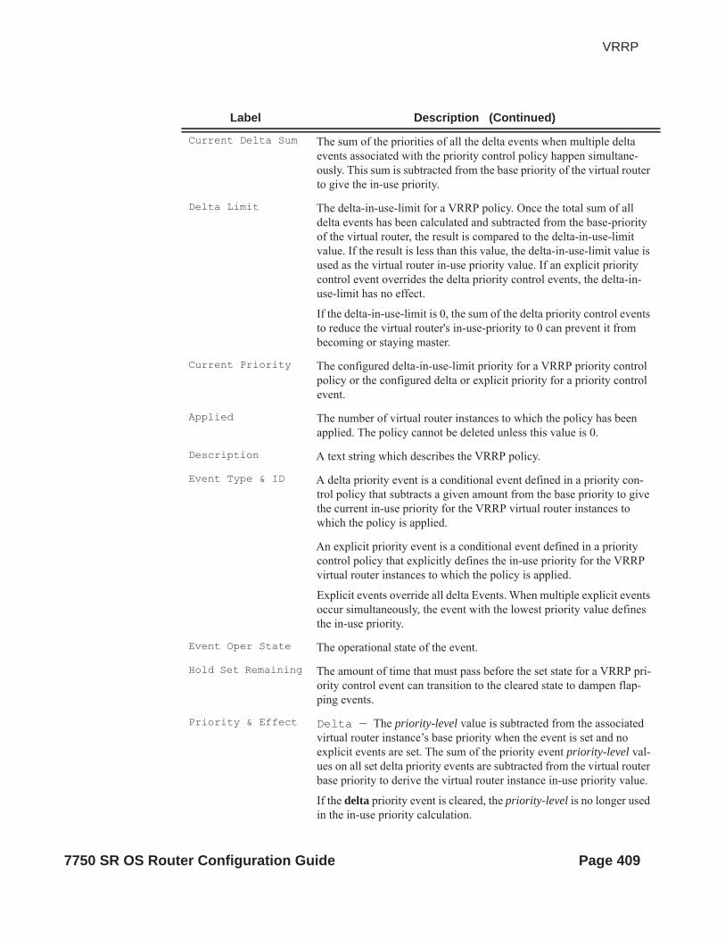
VRRP
Current Delta Sum The sum of the priorities of all the delta events when multiple delta events associated with the priority control policy happen simultane-ously. This sum is subtracted from the base priority of the virtual router to give the in-use priority.
Delta Limit The delta-in-use-limit for a VRRP policy. Once the total sum of all delta events has been calculated and subtracted from the base-priority of the virtual router, the result is compared to the delta-in-use-limit value. If the result is less than this value, the delta-in-use-limit value is used as the virtual router in-use priority value. If an explicit priority control event overrides the delta priority control events, the delta-in-use-limit has no effect.
If the delta-in-use-limit is 0, the sum of the delta priority control events to reduce the virtual router's in-use-priority to 0 can prevent it from becoming or staying master.
Current Priority The configured delta-in-use-limit priority for a VRRP priority control policy or the configured delta or explicit priority for a priority control event.
Applied The number of virtual router instances to which the policy has been applied. The policy cannot be deleted unless this value is 0.
Description A text string which describes the VRRP policy.
Event Type & ID A delta priority event is a conditional event defined in a priority con-trol policy that subtracts a given amount from the base priority to give the current in-use priority for the VRRP virtual router instances to which the policy is applied.
An explicit priority event is a conditional event defined in a priority control policy that explicitly defines the in-use priority for the VRRP virtual router instances to which the policy is applied.
Explicit events override all delta Events. When multiple explicit events occur simultaneously, the event with the lowest priority value defines the in-use priority.
Event Oper State The operational state of the event.
Hold Set Remaining The amount of time that must pass before the set state for a VRRP pri-ority control event can transition to the cleared state to dampen flap-ping events.
Priority & Effect Delta — The priority-level value is subtracted from the associated virtual router instance’s base priority when the event is set and no explicit events are set. The sum of the priority event priority-level val-ues on all set delta priority events are subtracted from the virtual router base priority to derive the virtual router instance in-use priority value.
If the delta priority event is cleared, the priority-level is no longer used in the in-use priority calculation.
Label Description (Continued)
7750 SR OS Router Configuration Guide Page 409

Sample Output
A:ALA-A# show vrrp policy===============================================================================VRRP Policies ===============================================================================Policy Current Current Current Delta Applied Id Priority & Effect Explicit Delta Sum Limit -------------------------------------------------------------------------------1 None None None 1 Yes 2 None None None 1 No ===============================================================================A:ALA-A#
A:ALA-A# show vrrp policy 1===============================================================================VRRP Policy 1 ===============================================================================Description : 10.10.200.253 reachability Current Priority: None Applied : No Current Explicit: None Current Delta Sum : None Delta Limit : 1 -------------------------------------------------------------------------------Applied To VR Opr Base In-use Master Is Interface Name Id Pri Pri Pri Master -------------------------------------------------------------------------------None -------------------------------------------------------------------------------Priority Control Events -------------------------------------------------------------------------------Event Type & ID Event Oper State Hold Set Priority In Remaining &Effect Use-------------------------------------------------------------------------------Host Unreach 10.10.200.252 n/a Expired 20 Del No Host Unreach 10.10.200.253 n/a Expired 10 Del No Route Unknown 10.10.100.0/24 n/a Expired 1 Exp No ===============================================================================A:ALA-A#
Explicit — The priority-level value is used to override the base priority of the virtual router instance if the priority event is set and no other explicit priority event is set with a lower priority-level.
The set explicit priority value with the lowest priority-level determines the actual in-use protocol value for all virtual router instances associ-ated with the policy.
In Use Specifies whether or not the event is currently affecting the in-use pri-ority of some virtual router.
Label Description (Continued)
Page 410 7750 SR OS Router Configuration Guide

VRRP
VRRP Policy Event Output — The following table describes a specific event VRRP policy com-mand output fields.
Label Description
Description A text string which describes the VRRP policy.
Policy Id The VRRP priority control policy associated with the VRRP virtual router instance.
A value of 0 indicates that no control policy is associated with the vir-tual router instance.
Current Priority The base router priority for the virtual router instance used in the mas-ter election process.
Current Explicit When multiple explicitly defined events associated with the priority control policy happen simultaneously, the lowest value of all the cur-rent explicit priorities will be used as the in-use priority for the virtual router.
Applied The number of virtual router instances to which the policy has been applied. The policy cannot be deleted unless this value is 0.
Current Delta Sum The sum of the priorities of all the delta events when multiple delta events associated with the priority control policy happen simultane-ously. This sum is subtracted from the base priority of the virtual router to give the in-use priority.
Delta Limit The delta-in-use-limit for a VRRP policy. Once the total sum of all delta events has been calculated and subtracted from the base-priority of the virtual router, the result is compared to the delta-in-use-limit value. If the result is less than this value, the delta-in-use-limit value is used as the virtual router in-use priority value. If an explicit priority control event overrides the delta priority control events, the delta-in-use-limit has no effect.
If the delta-in-use-limit is 0, the sum of the delta priority control events to reduce the virtual router's in-use-priority to 0 can prevent it from becoming or staying master.
Applied to Inter-face Name
The interface name where the VRRP policy is applied.
VR ID The virtual router ID for the IP interface.
Opr Up — Indicates that the operational state of the VRRP instance is up.
Down — Indicates that the operational state of the VRRP instance is down.
Base Pri The base priority used by the virtual router instance.
InUse Priority The current in-use priority associated with the VRRP virtual router instance.
7750 SR OS Router Configuration Guide Page 411

Master Priority The priority of the virtual router instance which is the current master.
Priority The base priority used by the virtual router instance.
Priority Effect Delta — A delta priority event is a conditional event defined in a priority control policy that subtracts a given amount from the base pri-ority to give the current in-use priority for the VRRP virtual router instances to which the policy is applied.
Explicit — A conditional event defined in a priority control pol-icy that explicitly defines the in-use priority for the VRRP virtual router instances to which the policy is applied.
Explicit events override all delta events. When multiple explicit events occur simultaneously, the event with the lowest priority value defines the in-use priority.
Current Priority The configured delta-in-use-limit priority for a VRRP priority control policy or the configured delta or explicit priority for a priority control event.
Event Oper State The operational state of the event.
Hold Set Remaining The amount of time that must pass before the set state for a VRRP pri-ority control event can transition to the cleared state to dampen flap-ping events.
Priority The base priority used by the virtual router instance.
Priority Effect Delta — The priority-level value is subtracted from the associated virtual router instance’s base priority when the event is set and no explicit events are set. The sum of the priority event priority-level val-ues on all set delta priority events are subtracted from the virtual router base priority to derive the virtual router instance in-use priority value.
If the delta priority event is cleared, the priority-level is no longer used in the in-use priority calculation.
Explicit — The priority-level value is used to override the base priority of the virtual router instance if the priority event is set and no other explicit priority event is set with a lower priority-level.
The set explicit priority value with the lowest priority-level determines the actual in-use protocol value for all virtual router instances associ-ated with the policy.
Hold Set Config The configured number of seconds that the hold set timer waits after an event enters a set state or enters a higher threshold set state, depending on the event type.
Value In Use Yes — The event is currently affecting the in-use priority of some virtual router.
Label Description (Continued)
Page 412 7750 SR OS Router Configuration Guide

VRRP
Sample Output
A:ALA-A#show vrrp policy 1 event port-down===============================================================================VRRP Policy 1, Event Port Down 1/1/1 ===============================================================================Description : Current Priority: None Applied : Yes Current Explicit: None Current Delta Sum : None Delta Limit : 1 -------------------------------------------------------------------------------Applied To VR Opr Base In-use Master Is Interface Name Id Pri Pri Pri Master -------------------------------------------------------------------------------ies301backup 1 Down 100 100 0 No -------------------------------------------------------------------------------Priority Control Event Port Down 1/1/1 -------------------------------------------------------------------------------Priority : 30 Priority Effect : Delta Hold Set Config : 0 sec Hold Set Remaining: Expired Value In Use : No Current State : Cleared # trans to Set : 6 Previous State : Set-down Last Transition : 04/13/2007 04:54:35 ===============================================================================A:ALA-A#
A:ALA-A# show vrrp policy 1 event host-unreachable===============================================================================VRRP Policy 1, Event Host Unreachable 10.10.200.252 ===============================================================================Description : 10.10.200.253 reachability Current Priority: None Applied : No Current Explicit: None Current Delta Sum : None Delta Limit : 1 -------------------------------------------------------------------------------Applied To VR Opr Base In-use Master Is Interface Name Id Pri Pri Pri Master -------------------------------------------------------------------------------None -------------------------------------------------------------------------------Priority Control Event Host Unreachable 10.10.200.252 -------------------------------------------------------------------------------Priority : 20 Priority Effect : Delta Interval : 1 sec Timeout : 1 sec Drop Count : 3 Hold Set Config : 0 sec Hold Set Remaining: Expired
No — The event is not affecting the in-use priority of some virtual router.
# trans to Set The number of times the event has transitioned to one of the 'set' states.
Last Transition The time and date when the operational state of the event last changed.
Label Description (Continued)
7750 SR OS Router Configuration Guide Page 413

Value In Use : No Current State : n/a # trans to Set : 0 Previous State : n/a Last Transition : 04/13/2007 23:10:24 ===============================================================================A:ALA-A#
A:ALA-A# show vrrp policy 1 event route-unknown===============================================================================VRRP Policy 1, Event Route Unknown 10.10.100.0/24 ===============================================================================Description : 10.10.200.253 reachability Current Priority: None Applied : No Current Explicit: None Current Delta Sum : None Delta Limit : 1 -------------------------------------------------------------------------------Applied To VR Opr Base In-use Master Is Interface Name Id Pri Pri Pri Master -------------------------------------------------------------------------------None -------------------------------------------------------------------------------Priority Control Event Route Unknown 10.10.100.0/24 -------------------------------------------------------------------------------Priority : 1 Priority Effect : Explicit Less Specific : No Default Allowed : No Next Hop(s) : None Protocol(s) : None Hold Set Config : 0 sec Hold Set Remaining: Expired Value In Use : No Current State : n/a # trans to Set : 0 Previous State : n/a Last Transition : 04/13/2007 23:10:24 ===============================================================================A:ALA-A#
statistics
Syntax statistics
Context show>router>vrrp
Description This command displays statistics for VRRP instance.
Output VRRP Statistics Output — The following table describes the VRRP statistics output fields.
Table 7: Show VRRP Statistics Output
Label Description
VR Id Errors Displays the number of virtual router ID errors.
Version Errors Displays the number of version errors.
Checksum Errors Displays the number of checksum errors.
Page 414 7750 SR OS Router Configuration Guide

VRRP
Sample Output
A:ALA-48# show router vrrp statistics===============================================================================VRRP Global Statistics===============================================================================VR Id Errors : 0 Version Errors : 0Checksum Errors : 0===============================================================================A:ALA-48#
7750 SR OS Router Configuration Guide Page 415

Monitor Commands
instance
Syntax instance interface interface-name vr-id virtual-router-id [ipv6] [interval seconds] [repeat repeat] [absolute | rate]
Context monitor>router>vrrp
Description Monitor statistics for a VRRP instance.
Parameters interface-name — The name of the existing IP interface on which VRRP is configured.
vr-id virtual-router-id — The virtual router ID for the existing IP interface, expressed as a decimal integer.
interval seconds — Configures the interval for each display in seconds.
Default 5 seconds
Values 3 — 60
repeat repeat — Configures how many times the command is repeated.
Default 10
Values 1 — 999
absolute — When the absolute keyword is specified, the raw statistics are displayed, without pro-cessing. No calculations are performed on the delta or rate statistics.
rate — When the rate keyword is specified, the rate-per-second for each statistic is displayed instead of the delta.
ipv6 — Specifies to monitor IPv6 instances.
Sample Output
*A:ALA-A# monitor router vrrp instance interface n2 vr-id 1 ===============================================================================Monitor statistics for VRRP Instance 1 on interface "n2"===============================================================================-------------------------------------------------------------------------------At time t = 0 sec (Base Statistics)-------------------------------------------------------------------------------Become Master : 1 Master Changes : 1 Adv Sent : 1439 Adv Received : 0 Pri Zero Pkts Sent : 0 Pri Zero Pkts Rcvd: 0 Preempt Events : 0 Preempted Events : 0 Mesg Intvl Discards : 0 Mesg Intvl Errors : 0 Addr List Discards : 0 Addr List Errors : 0 Auth Type Mismatch : 0 Auth Failures : 0 Invalid Auth Type : 0 Invalid Pkt Type : 0 IP TTL Errors : 0 Pkt Length Errors : 0 Total Discards : 0 ===============================================================================
Page 416 7750 SR OS Router Configuration Guide

VRRP
*A:ALA-A#
*A:ALA-A# monitor router vrrp instance interface n2 vr-id 10 ipv6 ===============================================================================Monitor statistics for VRRP Instance 10 on interface "n2"===============================================================================-------------------------------------------------------------------------------At time t = 0 sec (Base Statistics)-------------------------------------------------------------------------------Master Transitions : 1 Discontinuity Time: 09/09/2004 01:57*Adv Sent : 1365 Adv Received : 0 Pri Zero Pkts Sent : 0 Pri Zero Pkts Rcvd: 0 Preempt Events : 0 Preempted Events : 0 Mesg Intvl Discards : 0 Mesg Intvl Errors : 0 Total Discards : 0 Addr List Errors : 0 Auth Failures : 0 Invalid Pkt Type : 0 IP TTL Errors : 0 Pkt Length Errors : 0 ===============================================================================*A:ALA-A#
7750 SR OS Router Configuration Guide Page 417

Clear Commands
interface
Syntax interface ip-int-name [vrid virtual-router-id]interface ip-int-name vrid virtual-router-id ipv6
Context clear>router>vrrp
Description This command resets VRRP protocol instances on an IP interface.
Parameters ip-int-name — The IP interface to reset the VRRP protocol instances.
vrid vrid — Resets the VRRP protocol instance for the specified VRID on the IP interface.
Default All VRIDs on the IP interface.
Values 1 — 255
ipv6 — Clears IPv6 information for the specified interface.
statistics
Syntax statistics [policy policy-id]
Context clear>router>vrrp
Description This command enables the context to clear and reset VRRP entities.
Parameters policy policy-id — Clears statistics for the specified policy.
Values 1 — 9999
statistics
Syntax statistics interface interface-name [vrid virtual-router-id]statisticsstatistics interface interface-name vrid virtual-router-id ipv6
Context clear>router>vrrp
Description This command clears statistics for VRRP instances on an IP interface or VRRP priority control poli-cies.
Parameters interface ip-int-name — Clears the VRRP statistics for all VRRP instances on the specified IP inter-face.
Page 418 7750 SR OS Router Configuration Guide

VRRP
vrid virtual-router-id — Clears the VRRP statistics for the specified VRRP instance on the IP inter-face.
Default All VRRP instances on the IP interface.
Values 1 — 255
policy [vrrp-policy-id] — Clears VRRP statistics for all or the specified VRRP priority control pol-icy.
Default All VRRP policies.
Values 1 — 9999
ipv6 — Clears IPv6 statistics for the specified interface.
7750 SR OS Router Configuration Guide Page 419

VRRP Debug Commands
events
Syntax eventsevents interface ip-int-name [vrid virtual-router-id]events interface ip-int-name vrid virtual-router-id ipv6no eventsno events interface ip-int-name vrid virtual-router-id ipv6no events interface ip-int-name [vrid virtual-router-id]
Context debug>router>vrrp
Description This command enables debugging for VRRP events.
The no form of the command disables debugging.
Parameters ip-int-name — Displays the specified interface name.
vrid virtual-router-id — Displays the specified VRID.
ipv6 — Debugs the specified IPv6 VRRP interface.
packets
Syntax packets interface ip-int-name [vrid virtual-router-id]packetsno packets interface ip-int-name [vrid virtual-router-id] [ipv6]no packets
Context debug>router>vrrp
Description This command enables debugging for VRRP packets.
The no form of the command disables debugging.
Parameters ip-int-name — Displays the specified interface name.
vrid virtual-router-id — Displays the specified VRID.
Page 420 7750 SR OS Router Configuration Guide

Filter Policies
In This ChapterThe SROS supports filter policies for services and network interfaces (described in this chapter), subscriber management (integrated with service filter policies with the subscriber management specifics defined in the SROS Triple Play Guide), and CPM security and Management Interface (described in SROS Router Configuration Guide).
Topics in this chapter include:
• ACL Filter Policy Overview on page 422 Filter Policy Packet Match Criteria on page 423 IPv4/IPv6 Filter Policy Entry Match Criteria on page 423 MAC Filter Policy Entry Match Criteria on page 426 Filter Policy Actions on page 428 Filter Policy Statistics on page 429 Filter Policy Logging on page 431 Filter Policy cflowd Sampling on page 431 Filter policy management on page 432 Match-list for Filter Policies on page 434 Embedded Filters on page 437 ISID MAC Filters on page 438 VID MAC filters on page 439 Redirect Policies on page 443 HTTP-redirect (Captive Portal) on page 444 Filter Policies and Dynamic, Policy-Driven Interfaces on page 446
7750 SR OS Router Configuration Guide Page 421

ACL Filter Policy Overview
ACL Filter Policy OverviewACL Filter policies, also referred to as Access Control Lists (ACLs) or filters for short, are sets of ordered rule entries specifying packet match criteria and actions to be performed to a packet upon a match. Filter policies are created with a unique filter ID, but each filter can also have a unique filter name configured once the filter policy has been created. Either filter ID or filter name can be used throughout the system to manage filter policies and assign them to interfaces.
There are three main types of filter policies: IPv4, IPv6, and MAC filter policies. Additionally MAC filter policies support three sub-types: (configure filter mac-filter type {normal | isid | vid}). These sub-types allow operators to configure different L2 match criteria for a L2 MAC filter.
There are different kinds of filter policies as defined by the filter policy scope:
• An exclusive filter allows defining policy rules explicitly for a single interface. An exclusive filter allows highest-level of customization but uses most resources, since each exclusive filter consumes H/W resources on line cards the interface exists.
• A template filter allows usage of identical set of policy rules across multiple interfaces. Template filters use a single set of resources per line card, regardless of how many interfaces use a given template filter policy on that line card. Template filter policies used on access interfaces, consume resources on line cards only if at least one access interface for a given template filter policy is configured on a given line card.
• An embedded filter allows defining common set of policy rules that can then be used (embedded) by other exclusive or template filters in the system. This allows optimized management of filter policies.
Once created, filter policies must then be associated with interfaces/services/subscribers or with other filter policies (if the created policy cannot be directly deployed on interface/services/subscriber), so the incoming/outgoing traffic can be subjected to filter rules. Filter policies are associated with interfaces/services/subscribers separately in ingress and in egress direction. A policy deployed on ingress and egress direction can be same or different. In general, it is recommended to use different filter policies per-ingress and per-egress directions and to use different filter policies per service type, since filter policies support different match criteria and different actions for different direction/service contexts. A filter policy is applied to a packet in the ascending rule entry order. When a packet matches all the parameters specified in a filter entry’s match criteria, the system takes the action defined for that entry. If a packet does not match the entry parameters, the packet is compared to the next higher numerical filter entry rule and so on. If the packet does not match any of the entries, the system executes the default-action specified in the filter policy: drop or forward.
For Layer 2, either an IPv4/IPv6, and MAC filter policy can be applied. For Layer 3 and network interfaces, an IPv4/IPv6 policy can be applied. For r-VPLS service, a L2 filter policy can be applied to L2 forwarded traffic and L3 filter policy can be applied to L3 routed traffic. For dual stack interfaces, if both IPv4 and IPv6 filter policies are configured, the policy applied will be
Page 422 7750 SR OS Router Configuration Guide

Filter Policies
based on the outer IP header of the packet. Note that non-IP packets are not hitting an IP filter policy, so the default action in the IP filter policy will not apply to these packets.
Filter Policy Basics
The following subsections define main functionality supported by filter policies.
Filter Policy Packet Match Criteria
This section defines packet match criteria supported on SROS-based routers/switches for IPv4, IPv6 and MAC filters. Types of criteria supported depends on the hardware platform and filter direction, please see your Alcatel-Lucent representative for further details.
General notes:
• If multiple unique match criteria are specified in a single filter policy entry, all criteria must be met in order for the packet to be considered a match against that filter policy entry (logical AND).
• Any match criteria not explicitly defined is ignored during match. • An ACL filter policy entry with match criteria defined but no action configured, is
considered incomplete and inactive (an entry is not downloaded to the line card). A filter policy must have at least single entry active for the policy to be considered active.
• An ACL filter entry with no match conditions defined matches all packets.• Because an ACL filter policy is an order list, entries should be configured (numbered)
from the most explicit to the least explicit.
IPv4/IPv6 Filter Policy Entry Match Criteria
The below lists IPv4 and IPv6 match criteria supported by SROS routers/switches. The criteria are evaluated against outer IPv4/IPv6 header and a L4 header that follows (if applicable). Support for a given match criteria may depend on H/W and/or filter direction as per below description. It is recommended not to configure a filter in a direction or on a H/W where a given match condition is not supported as this may lead to undesired behavior. Some match criteria may be grouped in match lists and may be auto-generated based on router configuration – see Advanced Filter Policy topics for more details.
Basic L3 match criteria:
• dscp — Match for the specified DSCP value against the Differentiated Services Code Point/Traffic Class field in the IPv4/v6 packet header.
7750 SR OS Router Configuration Guide Page 423
ACL Filter Policy Overview
• src-ip/dst-ip — Match for the specified source/destination IPv4/IPv6 address-prefix against the source/destination IPv4/IPv6 address field in the IPv4/IPv6 packet header. Operator can optionally configure a mask to be used in a match.
• flow-label — Match for the specified flow label against the Flow label field in IPv6 packet . Operator can optionally configure a mask to be used in a match. Supported for ingress filters only. Requires minimum chassis mode C.
• packet-length — Match for the specified packet-length value/range against the Total Length field in IPv4 packet. This match condition is supported for drop action only and is part of action evaluation – i.e. after packet is determined to match the entry based on other match criteria configured. Packets that match all match criteria for a given filter policy entry are dropped if the packet-length match criterion is met and forwarded if the packet match criterion is not met. Supported for ingress filters only. Requires minimum FP-2 based line cards. The match is always true if filter is configured on egress or on older H/W.
Fragmentation match criteria:
• fragment — Enable fragmentation support in filter policy match. For IPv4, match against MF bit or Fragment Offset field to determine whether the packet is a fragment or not. For IPv6, match against Next Header Field for Fragment Extension Header value to determine whether the packet is a fragment or not. Up to 6 extension headers are matched against to find Fragmentation Extension Header.
Additional, match against whether the fragment is an initial fragment or non-initial fragment is also supported for IPv6 filters. These match criteria are supported on ingress only and require minimum FP-2 based line cards.
IPv4 options match criteria:
• ip-option — Match for the specified option value in the first option of the IPv4 packet. Operator can optionally configure a mask to be used in a match.
• option-present — Match for the presence or absence of the IP options in the IPv4 packet. Padding and EOOL are also considered as IP options. Up to 6 IP options are matched against.
• multiple-options — Match for the presence of multiple IP options in the IPv4 packet.• src-route-option — Match for the presence of IP Option 3 or 9 (Loose or Strict Source
Route) in the first 3 IP Options of the IPv4 packet. A packet will also match this rule if the packet has more than 3 IP Options.
IPv6 next-header match criteria (see also Upper-layer protocol match next-header description below):
• ah-ext-header — Match for presence/absence of the Authentication Header extension header in the IPv6 packet. This match criterion is supported on ingress only and requires minimum FP-2 based line cards. Up to 6 extension headers are matched against.
Page 424 7750 SR OS Router Configuration Guide
Filter Policies
• esp-ext-header — Match for presence/absence of the Encapsulating Security Payload extension header in the IPv6 packet. This match criterion is supported on ingress only and requires minimum FP-2 based line cards. Up to 6 extension headers are matched against.
• hop-by-hop-opt — Match for the presence/absence of Hop-by-hop options extension header in the IPv6 packet. This match criterion is supported on ingress only and requires minimum FP-2 based line cards. Up to 6 extension headers are matched against.
• routing-type0 — Match for the presence/absence of Routing extension header type 0 in the IPv6 packet. This match criterion is supported on ingress only and requires minimum FP-2 based line cards. Up to 6 extension headers are matched against.
Upper-layer protocol match:
• next-header — Match for the specified upper layer protocol (for example, TCP, UDP, IGMPv6) against the Next Header field of the IPv6 packet header. “*” can be used to specify TCP or UDP upper-layer protocol match (Logical OR). Note: next-header matching allows also matching on presence of a subset of IPv6 extension headers. See CLI section for details on which extension header match is supported.
• protocol — Match for the specified protocol against the Protocol field in the IPv4 packet header (for example, TCP, UDP, IGMP) of the outer IPv4. “*” can be used to specify TCP or UDP upper-layer protocol match (Logical OR).
• icmp-code — Match for the specified value against the Code field of the ICMP/ICMPv6 header of the packet. This match is supported only for entries that also define protocol/next-header match for “ICMP”/”ICMPv6” protocol.
• icmp-type — Match for the specified value against the Type field of the ICMP/ICMPv6 header of the packet. This match is supported only for entries that also define protocol/next-header match for “ICMP”/”ICMPv6” protocol.
• src-port/dst-port – Match for the specified port value or port range against the Source Port Number/Destination Port Number of the UDP/TCP packet header. An option to match either source or destination (Logical OR) using a single filter policy entry is supported by using a directionless “port” command. Source/destination match is supported only for entries that also define protocol/next-header match for “TCP” or “UDP” or “TCP or UDP” protocols. Note that a non-initial fragment will never match an entry with port criteria specified.
• tcp-ack/tcp-syn — Match for the TCP ACK/TCP SYNC flag presence/absence in the TCP header of the packet. This match is supported only for entries that also define protocol/next-header match for “TCP” protocol.
7750 SR OS Router Configuration Guide Page 425

ACL Filter Policy Overview
MAC Filter Policy Entry Match Criteria
The below lists MAC match criteria supported by SROS routers/switches for all types of MAC filters (normal, isid, and vid). The criteria are evaluated against the Ethernet header of the Ethernet frame. Support for a given match criteria may depend on H/W and/or filter direction as per below description. Match criterion is blocked if it is not supported by a specified frame-type or MAC filter sub-type. It is recommended not to configure a filter in a direction or on a H/W where a given match condition is not supported as this may lead to undesired behavior.
• frame-type — Entering the frame type allows the filter to match for a specific type of frame format. For example, configuring frame-type ethernet_II will match only Ethernet-II frames.
• src-mac— Entering the source MAC address allows the filter to search for matching a source MAC address frames. Operator can optionally configure a mask to be used in a match.
• dst-mac— Entering the destination MAC address allows the filter to search for matching destination MAC address frames. Operator can optionally configure a mask to be used in a match.
• dot1p — Entering an IEEE 802.1p value allows the filter to search for matching 802.1p frames. Operator can optionally configure a mask to be used in a match.
• etype— Entering an Ethertype value allows the filter to search for matching Ethernet II frames. The Ethernet type field is a two-byte field used to identify the protocol carried by the Ethernet frame.
• ssap— Entering an Ethernet 802.2 LLC SSAP value allows the filter to search for matching frames with a source access point on the network node designated in the source field of the packet. Operator can optionally configure a mask to be used in a match.
• dsap— Entering an Ethernet 802.2 LLC DSAP value allows the filter to search for matching frames with a destination access point on the network node designated in the destination field of the packet.. Operator can optionally configure a mask to be used in a match.
• snap-oui— Entering an Ethernet IEEE 802.3 LLC SNAP OUI allows the filter to search for matching frames with the specified the three-byte OUI field.
• snap-pid— Entering an Ethernet IEEE 802.3 LLC SNAP PID allows the filter to search for the matching frames with the specified two-byte protocol ID that follows the three-byte OUI field.
• isid — Entering an Ethernet IEEE 802.1ag ISID from the I-TAG value allows the filter to search for the matching Ethernet frames with the 24 bits ISID value from the PBB I-TAG. This match criterion is mutually exclusive with all the other match criteria under a particular mac-filter policy and is applicable to MAC filters of type isid only. The resulting mac-filter can only be applied on a BVPLS SAP or PW in the egress direction.
Page 426 7750 SR OS Router Configuration Guide

Filter Policies
• inner-tag/outer-tag — Entering inner-tag/outer-tag VLAN ID values allows the filter to search for the matching Ethernet frames with the non-service delimiting tags as described In “VID MAC filters” subsection later-on this. This match criterion is mutually exclusive with all other match criteria under a particular mac-filter policy and is applicable to MAC filters of type vid only.
7750 SR OS Router Configuration Guide Page 427

ACL Filter Policy Overview
Filter Policy Actions
The following lists actions supported by ACL filter policies
• drop — This action allows operator to deny traffic to ingress/egress the system• forward — This action allows operator to permit traffic to ingress/egress the system and
be subject to regular processing• forward “Policy-based Routing/Forwarding (PBR/PBF) action”— PBR/PBF actions
allows operator to permit ingress traffic but change the regular routing/forwarding packet would be a subject to. The PBR/PBF is applicable to unicast traffic only. The following PBR/PBF actions are supported (See CLI section for command details): router — changes the routing instance a packet is routed in from the upcoming
interface’s instance to the routing instance specified in the PBR action (supports both GRT and VPRN redirect). Requires network interfaces to be on FP2 line cards or newer. Supported for ingress IPv4/IPv6filter policies only, deployed on L3 interfaces. Packets are dropped if they cannot be routed in the configured routing instance. Requires minimum Chassis mode D.
next-hop — changes the IP destination address used in routing from the address in the packet to the address configure in this PBR action. The operator can configure whether the next-hop IP address must be direct (local subnet only) or indirect (any IP). Supported for ingress IPv4/IPv6 filter policies only, deployed on L3 interfaces. If configured next-hop is not reachable, traffic is dropped and “ICMP destination unreachable” message is sent. For IPv6, requires minimum Chassis mode C.
lsp — forwards the incoming traffic onto the specified LSP. Supports RSVP-TE LSPs(type static or dynamic only) or MPLS-TP LSPs. Supported for ingress IPv4/IPv6 filter policies only deployed on IES SAPs or network interfaces. If the configured LSP is down, traffic matches the entry and action forward is executed.
interface — forwards the incoming traffic onto the specified IPv4 interface. Supported for ingress IPv4 filter policies in global routing table instance. If the configured interface is down or not of the supported type, traffic is dropped.
sap — forwards the incoming traffic onto the specified VPLS SAP. Supported for ingress IPv4/IPv6 and MAC filter policies deployed in VPLS service. The SAP traffic is to egress on must be in the same VPLS service as the incoming interface. If the configured SAP is down, traffic is dropped.
sdp — forwards the incoming traffic onto the specified VPLS SDP. Supported for ingress IPv4/IPv6 and MAC filter policies deployed in VPLS service. The SDP traffic is to egress on must be in the same VPLS service as the incoming interface. If the configured SDP is down, traffic is dropped.
Page 428 7750 SR OS Router Configuration Guide

Filter Policies
redirect-policy — implements PBR next-hop action with ability to select and prioritize multiple redirect targets and monitor the specified redirect targets so PBR action can be changed if the selected destination goes down. Supported for ingress IPv4 filter policies only, deployed on L3 interfaces. See Redirect Policies section later on for more details
• forward “isa action” — ISA processing actions allow operator to permit ingress traffic and send it for ISA processing as per specified isa action. The following isa actions are supported (see CLI section for command details): nat — forwards matching traffic for NAT. Supported for IPv4/IPv6 filter policies for
L3 services in GRT or VPRN. If ISAs performing NAT are down, traffic is dropped. (see CLI for options)
reassemble — forwards matching packets to the reassembly function. Supported for IPv4 ingress filter policies only. If ISAs performing reassemble are down, traffic is dropped.
gtp-local-breakout — forwards matching traffic to NAT instead of being GTP tunneled to the mobile operator’s PGW or GGSN. The action applies to GTP-subscriber-hosts. If filter is deployed on other entities, action forward is applied. Supported for IPv4 ingress filter policies only. If ISAs performing NAT are down, traffic is dropped.
• http-redirect — implements HTTP redirect captive portal. HTTP GET is forwarded to CPM card for captive portal processing by router. See HTTP-redirect (Captive Portal) section for further details.
In addition to the above actions, operator can select a default-action for a filter policy. Default action is executed on packets subjected to an active filter when none of the filter’s active entries matches the packet. By default, filter policies have default action set to drop but operator can select a default action to be forward instead.
Filter Policy Statistics
Filter policies support per-entry, packet match debug statistics. The cumulative matched packet counters are available per ingress and per egress direction. Every packet arriving on an interface/service/subscriber using a filter policy increments ingress or egress (as applicable) matched packet count for a filter entry the packet matches (if any) on the line card the packet ingresses/egresses. For each policy, the counters for all entries are collected from all line cards, summed up and made available to an operator.
Starting with SROS Release 11.0 R4, filter policies applied on access interfaces are downloaded only when active and only to line cards that have interfaces associated with those filter policies. If a filter policy is not downloaded to any line card, the statistics show 0 (zero). If a filter policy is
7750 SR OS Router Configuration Guide Page 429

ACL Filter Policy Overview
being removed from any of the line cards the policy is currently downloaded to (as result of association change or when a filter becomes inactive), the debug statistics for the filter are reset to 0 (zero). Downloading a filter policy to a new line card keeps incrementing existing statistics.
Page 430 7750 SR OS Router Configuration Guide

Filter Policies
Filter Policy Logging
SROS supports logging of the information from the packets that match given filter policy. Logging is configurable per filter policy entry by specifying pre-configured filter log (config filter log). A filter log can be applied to ACL filters and CPM hardware filters. Operator can configure multiple filter logs and specify: memory allocated to a filter log destination, syslog id for filter log destination, filter logging summarization, and wrap-around behavior.
Notes related to filter log summarization:
• The implementation of the feature applies to filter logs with destination syslog.• Summarization logging is the collection and summarization of log messages for 1 specific
log-id within a period of time.• The summarization interval is 100 seconds.• Upon activation of a summary, a mini-table with src/dst-address and count is created for
each type (IP/IPv6/MAC).• Every received log packet (due to filter hit) is examined for source or destination address.• If the log packet (source/destination address) matches a source/destination address entry in
the mini-table a packet received previously), the summary counter of the matching address is incremented.
• If source or destination address of the log messages does not match an entry already present in the table, the source/destination address is stored in a free entry in the mini-table.
• In case the mini-table has no more free entries, only total counter is incremented.• At expiry of the summarization interval, the mini-table for each type is flushed to the
syslog destination.
Filter Policy cflowd Sampling
Filter policies can be used to control how cflowd sampling is performed on an IP interface. If an IP interface has cflowd sampling enabled, an operator can exclude some flows for interface sampling by configuring filter policy rules that match the flows and by disabling interface sampling as part of the filter policy entry configurations (interface-disable-sample). If an IP interface has cflowd sampling disabled, an operator can enable cflowd sampling on a subset of flows by configuring filter policy rules that match the flows and by enabling cflowd sampling as part of the filter policy entry configurations (filter-sample).
Note that the above cflowd filter sampling behavior is exclusively driven by match criteria: The sampling logic applies regardless of whether an action was executed or not (including evaluation of packet-length match condition).
7750 SR OS Router Configuration Guide Page 431
ACL Filter Policy Overview
Filter policy management
Modifying Existing Filter Policy
There are several ways to modify an existing filter policy. A filter policy can be modified through configuration change or can have entries populated through dynamic, policy-controlled dynamic interfaces like Radius or OpenFlow or Flowspec or Gx for example. Although in general, the SROS ensures filter resources exist before a filter can be modified, because of a dynamic nature of the policy-controlled interfaces, a configuration that was accepted may not be applied in H/W due to lack of resources. When that happens, an error is raised.
A filter policy can be modified directly – by changing/adding/deleting the existing entry in that filter policy or indirectly. Examples of indirect change to filter policy include, among others, changing embedded filter entry this policy embeds (see Embedded filters section), changing redirect policy this filter policy uses.
Finally, a filter policy deployed on a given interface can be changed by changing the policy the interface is associated with.
All of the above changes can be done in service. Note that a filter policy that is associated with service/interface cannot be deleted unless all associations are removed first.
For a large (complex) filter policy change, it may take a few seconds to load and initiate the filter policy configuration. It should also be noted, that filter policy changes are downloaded to line cards immediately, therefore operators should use filter policy copy or transactional CLI to ensure partial policy change is not activated.
Filter Policy Copy and Renumbering
To assist operators in filter policy management, SROS supports entry copy and entry renumbering operations.
Filter copy allows operators to perform bulk operations on filter policies by copying one filter’s entries to another filter. Either all entries or a specified entry of the source filter can be selected for copy. When entries are copied, entry order is preserved unless destination filter’s entry ID is selected (applicable to single entry copy). The filter copy allows overwrite of the existing entries in the destination filter by specifying “overwrite” option during the copy command. Filter copy can be used, for example, when creating new policies from existing policies or when modifying an existing filter policy (an existing source policy is copied to a new destination policy, the new destination policy is modified, then the new destinations policy is copied back the source policy with overwrite specified).
Page 432 7750 SR OS Router Configuration Guide

Filter Policies
Entry renumbering allows operator to change relative order of a filter policy entry by changing the entry Id. Entry renumbering can also be used to move 2 entries closer together or further apart, thus creating additional entry space for new entries.
7750 SR OS Router Configuration Guide Page 433

ACL Filter Policy Overview
Filter Policy Advanced Topics
Match-list for Filter Policies
Figure 14 depicts an approach to implement logical OR on a list of matching criterion (IPv4 address prefixes in this example) in one or more filter policies prior to introduction of match list.
Figure 14: IOM/CPM Filter Policy using Individual Address Prefixes
An operator has to create one entry for each address prefix to execute a common action. Each entry defines a match on a unique address prefix from the list plus any other additional match criteria and the common action. If the same set of address prefixes needs to be used in another IOM or CPM filter policy, an operator again needs to create one entry for each address prefix of the list in those filter policies. Same procedure applies (not shown above) if another action needs to be performed on the list of the addresses within the same filter policy (when for example specifying different additional match criteria). This process can introduce large operational overhead, especially when a list contains many elements or/and needs to be reused multiple times across one or more filter policies.
Match list for CPM and IOM filter policies are introduced to eliminate above operational complexity by simplifying the IOM and CPM filter policy management on a list of a match criterion. Instead of defining multiple filter entries in any given filter, an operator can now group same type of the matching criteria into a single filter match list, and then use that list as a match criterion value, thus requiring only single filter policy entry per each unique action. The same match list can be used in one or more IOM filter policies as well as CPM filter policies.
The match lists further simplify management and deployment of the policy changes. A change in a match-list content is automatically propagated across all policies employing that list in their match criteria, thus only a single configuration change is required to trigger policy changes when a list is used by multiple entries in one or more filter policies.
Entry K+1+1: match IPv4 Prefix 1
Entry K+2: match IPv4 Prefix 2
Entry K+Nmatch IPv4 Prefix N
CPM FilterIOM Filters
OSSG729
Entry M+1match IPv4 Prefix 1
Entry M+2match IPv4 Prefix 2
Entry M+Nmatch IPv4 Prefix N
IPv4 Prefix 1
IPv4 Prefix 2
IPv4 Prefix N
Page 434 7750 SR OS Router Configuration Guide

Filter Policies
Figure 15 depicts how the IOM/CPM filter policy illustrated at the top of this section changes with a filter match list usage (using IPv4 address prefix list in this example).
Figure 15: IOM/CPM Filter Policy Using an Address Prefix Match List
Note: The hardware resource usage does not change whether filter match lists are used or whether operator creates multiple entries (each per one element of the list): however, a careful consideration must be given to how the lists are used to ensure only desired match permutations are created in a filter policy entry (especially when other matching criteria that are also lists or ranges are specified in the same entry). The system verifies that a new list element, for example, an IP address prefix, cannot be added to a given list or a list cannot be used by a new filter policy unless resources exist in hardware to implement the required filter policy (ies) that reference that list. If that is not the case, addition of a new element to the list or use of the list by another policy will fail.
Some use cases like those driven by dynamic policy changes, may result in acceptance of filter policy configuration changes that cannot be programmed in hardware because of the resource exhaustion. If that is the case, when attempting to program a filter entry that uses a match list(s), the operation will fail, the entry will be not programmed, and a notification of that failure will be provided to an operator.
Please refer to SROS Release Notes for what objects can be grouped into a filter match list for IOM and CPM filter policies.
Entry Kmatch: IPv4 Prefix List A
CPM FilterIOM Filters
OSSG730
Entry Mmatch: IPv4 Prefix List A
IPv4 Prefix 1
IPv4 Prefix 2
IPv4 Prefix N
IPv4 Prefix List A
7750 SR OS Router Configuration Guide Page 435

ACL Filter Policy Overview
Auto-generation of Filter-policy Address Prefix Match Lists
It is often desired to automatically update a filter policy when the configuration on a router changes. To allow such a touch-less filter policy management, SROS allows auto-generation of address prefixes for IPv4 or IPv6 address prefix match lists based on operator-configured criteria. When the configuration on a router changes, the match lists address prefixes are automatically updated and, in-turn, all filter policies (CPM or IOM) that use these match lists are automatically updated.
When using auto-generation of address prefixes inside an address prefix match list operators can:
• Specify one or more regex expression matches against SROS router configuration per list.• Specify wildcard matches by specifying regex wildcard match expression (“.*”).• Mix auto-generated entries with statically configured entries within a match list.
The following additional rules apply to auto-generated entries:
• Operational and administrative states of a given router configuration are ignored when auto-generating address prefixes.
• Duplicates are not removed when populated by different auto-generation matches and static configuration.
• A configuration will fail if auto-generation of address prefix would result in filer policy resource exhaustion on a filter entry, system, or line-card level.
The following may apply to this feature:
If filter policy resources are not available for newly auto-generated address prefixes when a BGP configuration changes, new address-prefixes will not be added to impacted match lists or filter policies as applicable. An operator must free resources and change filter policy configuration or must change BGP configuration to recover from this failure.
NOTE: See Release notes and CLI section for details on what configuration supports address prefix list auto-generation.
Page 436 7750 SR OS Router Configuration Guide

Filter Policies
Embedded Filters
When a large number of standard filter policies are configured in a system, a set of policies will often contain one or more common blocks of entries that define, for example, system-wide and/or service-wide security rules. Prior to introduction of the embedded filters, such common rules would have to be configured separately in each exclusive/template policy.
To simplify management of such common rules across multiple filter policies, operator can now use embedded filter policies. An embedded filter policy is a special type of a filter policy that cannot be deployed directly but instead is used to define a common filter policy rules that are then included in (embedded by) other filter policies in the system. Thanks to embedding, a common set of rules can now be defined and changed in a single place but deployed across multiple filter policies. The following main rules apply when embedding an embedded filter policy:
1. An operator can explicitly define an offset at which to embed a given embedded filter into a given embedding filter—the embedded filter entry number X becomes an entry (X + offset) in the embedding filter.
2. An exclusive/template filter policy may embed multiple embedded filter policies as long as the embedded entries do not overlap.
3. A single embedded filter policy may be embedded in many exclusive/template filter policies.4. When embedding an embedded filter, an operator may wish to change or deactivate an
embedded filter policy entry in one of the embedding filter, thus allowing for customizing of the common embedded filter policy rules by the embedding filter. This can be achieved by either defining an entry in the embedding filter that will match ahead of the embedded filter entry or by overwriting the embedded filter entry in the embedding filter.
For example: If embedded filter 99 has entry 20 that drops packets that match IP source address src_address, and filter 200 embeds filter 99 at offset 100, then to deactivate the embedded entry 20, an operator could define an entry 120 (embedded entry number 20 + off-set 100) in filter policy 200, that has the same match criteria and has either no action defined (this will deactivate the embedded entry and allow continued evaluation of filter policy 200), or has action forward defined (packets will match the new entry and will be forwarded instead of dropped, evaluation of filter policy 200 will stop).
5. Any embedded policy rule edits are automatically applied to all filter policies that embed that embedded filter policy.
6. The system verifies whether system and h/w resources exist when a new embedded filter pol-icy is created, changed or embedded. If resources are not available, the configuration is rejected. In rare cases, filter policy resource check may pass but filter policy can still fail to load due to a resource exhaustion on a line card (for example when other filter policy entries are dynamically configured by applications like RADIUS in parallel). If that is the case, the embedded filter policy configured will be de-activated (configuration will be changed from activate to inactivate).
7750 SR OS Router Configuration Guide Page 437
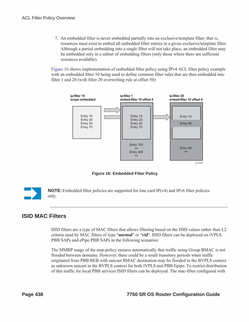
ACL Filter Policy Overview
7. An embedded filter is never embedded partially into an exclusive/template filter; that is, resources must exist to embed all embedded filter entries in a given exclusive/template filter. Although a partial embedding into a single filter will not take place, an embedded filter may be embedded only in a subset of embedding filters (only those where there are sufficient resources available).
Figure 16 shows implementation of embedded filter policy using IPv4 ACL filter policy example with an embedded filter 10 being used to define common filter rules that are then embedded into filter 1 and 20 (with filter 20 overwriting rule at offset 50):
Figure 16: Embedded Filter Policy
ISID MAC Filters
ISID filters are a type of MAC filters that allows filtering based on the ISID values rather than L2 criteria used by MAC filters of type "normal" or "vid". ISID filters can be deployed on iVPLS PBB SAPs and ePipe PBB SAPs in the following scenarios:
The MMRP usage of the mrp-policy ensures automatically that traffic using Group BMAC is not flooded between domains. However; there could be a small transitory periods when traffic originated from PBB BEB with unicast BMAC destination may be flooded in the BVPLS context as unknown unicast in the BVPLS context for both IVPLS and PBB Epipe. To restrict distribution of this traffic for local PBB services ISID filters can be deployed. The mac-filter configured with
Entry 10Entry 20Entry 50Entry 70
Entry 10Entry 20Entry 50Entry 70
Entry 100
Entry 300Entry 80
Entry 10
Entry 50
ip-filter 1embed-filter 10 offset 0
ip-filter 10scope embedded
ip-filter 20embed-filter 10 offset 0
al_0167
NOTE: Embedded filter policies are supported for line card IP(v4) and IPv6 filter policies only.
Page 438 7750 SR OS Router Configuration Guide

Filter Policies
ISID match criterion can be applied to the same interconnect endpoint(s), BVPLS SAP or PW, as the mrp-policy to restrict the egress transmission any type of frames that contain a local ISID. The ISID filters will be applied as required on a per B-SAP or B-PW basis just in the egress direction.
The ISID match criteria are exclusive with any other criteria under mac-filter. A new mac-filter type attribute is defined to control the use of ISID match criteria and must be set to ISID to allow the use of ISID match criteria.
VID MAC filters
VID Filters are a type of MAC filters that extend the capability of current Ethernet Ports with null or default SAP tag configuration to match and take action on VID tags. Service delimiting tags (for example QinQ 1/1/1:10.20 or dot1q 1/1/1:10, where outer tag 10 and inner tags 20 are service delimiting) allow fine grain control of frame operations based on the VID tag. Service delimiting tags are exact match and are stripped from the frame as illustrated in Figure 17. Exact match or service delimiting Tags do not require VID filters. VID filters can only be used to match on frame tags that are after the service delimiting tags.
With VID Filters operators can choose to match VID tags for up to two tags on ingress or egress or both.
• The outer-tag is the first tag in the packet that is carried transparently through the service. • The inner-tag is the second tag in the packet that is carried transparently through the
service.
VID Filters add the capability to perform VID value filter policies on default tags (1/1/1:* or 1/1/1:x.*, or 1/1/1/:*.0), or null tags ( 1/1/1, 1/1/1:0 or 1/1/1:x.0). The matching is based on the port configuration and the SAP configuration.
In the industry the QinQ tags are often referred to as the C-VID (Customer VID) and S-VID (service VID). The terms outer tag and inner tag allow flexibility without having to refer to C-TAG and an S-TAG explicitly. The position of inner and outer tags is relative to the port configuration and SAP configuration. Matching of tags is allowed for up to the first two tags on a frame. Since service delimiting tags may be 0, 1 or 2 tags.
The meaning of inner and outer has been designed to be consistent for egress and ingress when the number of non service delimiting tags is consistent. Service 1 in Figure 17 shows a conversion from qinq to a single dot1q example where there is one non-service delimiting tag on ingress and egress. Service 2 shows a symmetric example with two non-service delimiting tags (plus and additional tag for illustration) to two non-service delimiting tags on egress. Service 3 illustrates single non-service delimiting tags on ingress and to two tags with one non-service delimiting tag on ingress and egress.
7750 SR OS Router Configuration Guide Page 439

ACL Filter Policy Overview
SAP-ingress QoS setting allows for MAC-criteria type VID which uses the VID filter matching capabilities QoS and VID Filters (moved to QoS guide) on page 313.
A VID filter entry can also be used as a debug or lawful intercept mirror source entry.
Figure 17: VID Filtering Examples
VID filters are available on Ethernet SAPs for Epipe, VPLS or I-VPLS including eth-tunnel and eth-ring services.
MAC 10 20 ...Payload
MAC
Service Delimiting Tags: Stripped on Ingress and Added on Egress (Can not be used for matching)
Tags Carried Transparently by the Service
Tags Too Deep to be Service Delimiting or to be Used for VID Filtering
Tag Available for Matching and Indication of Which Match Criteria to Use
20 10 ...Payload
MAC 10 20 30 ...Payload MAC 10 20 30 ...PayloadMAC 10 20 30 ...Payload
MAC 20 ...PayloadMAC 20 ...Payload
MAC 20 ...Payload
Service 3
Service 2
Service 1
MAC 10 ...Payload
SAP 1/1/1:10.*
qinq dot1q
null null
dot1q
outer
dot1q
SAP 2/1/1:*
SAP 1/1/2 SAP 2/1/2
SAP 1/1/3:* SAP 2/1/3:20
outerIngress: Egress:
Egress:
Egress:
PortEncap
PortEncap
outer
outer
outer inner
outer
outer inner
OSSG735
Page 440 7750 SR OS Router Configuration Guide

Filter Policies
Arbitrary Bit Matching of VID Filters
In addition to matching an exact value, a VID filter mask allows masking any set of bits. The masking operation is ((value & vid-mask) = = (tag and vid-mask)). For example: A value of 6 and a mask of 7 would match all VIDs with the lower 3 bits set to 6. VID filters allow explicit matching of VIDs and matching of any bit pattern within the VID tag.
When using VID filters on SAPs only VID filters are allowed on this SAP. Filters of type normal and ISID are not allowed.
An additional check for the “0” VID tag may be required when using certain wild card operations. For example frames with no tags on null encapsulated ports will match a value of 0 in outer tag and inner tag because there are no tags in the frame for matching. If a zero tag is possible but not desired it can be explicitly filtered using exact match on “0” prior to testing other bits for “0”.
Note that configure>system>ethernet>new-qinq-untagged-sap is a special QinQ function for single tagged QinQ frames with a null second tag. Using this in combination with VID filters is not recommended. Note that the outer-tag is the only tag available for filtering on egress for frames arriving from MPLS SDPs or from PBB services even though additional tags may be carried transparently.
7750 SR OS Router Configuration Guide Page 441

ACL Filter Policy Overview
Port Group Configuration Example
Figure 18: Port Groups
Figure 18 shows a customer use example where some VLANs are prevented from ingressing or egressing certain ports. In the example, port A sap 1/1/1:1.* would have a filter as shown below while port A sap 1/1/1:2.* would not.:
mac-filter 4 createdefault-action forward
type vid entry 1 create match frame-type ethernet_II outer-tag 30 4095 exit action drop exit exit
OSSG734
C-VID Filters are Configured perSub-group (S-VID)
Legend
101
201
301
302
20
(Example)SVID=1 / CVID=30: DiscardSVID=2 / CVID=30: Forward
Discards FramesWith C-VIDNot in Contract
S-TAGC-TAG: Data
: Discard
Sub-group 2
D
A
B
C
Sub-group 1
10 30 30
30 40
Page 442 7750 SR OS Router Configuration Guide

Filter Policies
Redirect Policies
SROS-based routers support configuring of redirect policies. Redirect policies allow specifying multiple redirect target destinations and defining health check test methods used to validate the ability for a given destination to receive redirected traffic. This destination monitoring allows router to react to target destination failures.
Redirect policy supports the following destination tests:
• ping test – with with configurable interval, drop-count, and time-out for the test• url-test – with configurable URL to test; interval, drop-count and timeout for the test; and
configurable action (disable destination, lower or raise priority) based upon return error code
• snp-test - with configurable OID stand Community strings; interval, drop-count and timeout for the test; and configurable action (disable destination, lower or raise priority) based upon SNMP return value.
Each destination is assigned an initial or base priority describing this destination’s relative importance within the policy. The destination with the highest priority value is selected as most-preferred destination and programmed on line cards in filter policies using this redirect policy as an action. Note that only destinations that are not disabled by the programmed test (if configured) are considered when selecting the most-preferred destination. If the most-preferred destination is selected, forward redirect-policy action is equivalent to forward next-hop indirect “most-preferred destination” action. If none of the configured destinations is selected as most-preferred (all destinations are down or no destination are programmed in the policy), forward redirect-policy action is equivalent to forward action
Feature caveats:
• Redirect policy is supported for ingress IPv4 filter policies only• Redirect policy test are performed in GRT instance, even if the policy is deployed in
VPRN• Different platforms support different scale for redirect policies, please contact your local
Alcatel-Lucent representative to ensure the planned deployment does not exceed recommended scale
7750 SR OS Router Configuration Guide Page 443

ACL Filter Policy Overview
HTTP-redirect (Captive Portal)
Web redirection policies can be configured on SR OS routers/switches. The http redirection action can block a customer’s request from an intended recipient and force the customer to connect to the service’s portal server. 255 unique entries with http-redirect are allowed.
Traffic Flow
The following example provides a brief scenario of a customer connection with web redirection.
1. The customer gets an IP address using DHCP (if the customer is trying to set a static IP he will be blocked by the anti-spoofing filter).
2. The customer tries to connect to a website. 3. The router intercepts the HTTP GET request and blocks it from the network4. The router then sends the customer an HTTP 302 (service temporarily unavailable/moved).
The target URL should then include the customer’s IP and MAC addresses as part of the por-tal’s URL.
5. The customer’s web browser will then close the original connection and open a new connec-tion to the web portal.
6. The web portal updates the ACL (directly or through SSC) to remove the redirection policy. 7. The customer connects to the original site.
Page 444 7750 SR OS Router Configuration Guide
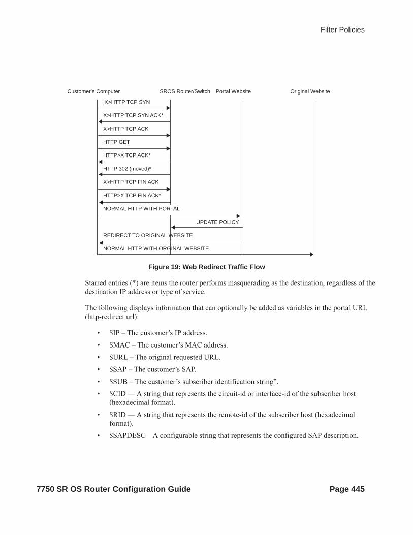
Filter Policies
Figure 19: Web Redirect Traffic Flow
Starred entries (*) are items the router performs masquerading as the destination, regardless of the destination IP address or type of service.
The following displays information that can optionally be added as variables in the portal URL (http-redirect url):
• $IP – The customer’s IP address.• $MAC – The customer’s MAC address.• $URL – The original requested URL.• $SAP – The customer’s SAP.• $SUB – The customer’s subscriber identification string”.• $CID — A string that represents the circuit-id or interface-id of the subscriber host
(hexadecimal format). • $RID — A string that represents the remote-id of the subscriber host (hexadecimal
format).• $SAPDESC – A configurable string that represents the configured SAP description.
Customer’s Computer SROS Router/Switch Portal Website Original Website
X>HTTP TCP SYN
X>HTTP TCP SYN ACK*
X>HTTP TCP ACK
HTTP GET
HTTP>X TCP ACK*
HTTP 302 (moved)*
X>HTTP TCP FIN ACK
HTTP>X TCP FIN ACK*
UPDATE POLICY
REDIRECT TO ORIGINAL WEBSITE
NORMAL HTTP WITH ORGINAL WEBSITE
NORMAL HTTP WITH PORTAL
7750 SR OS Router Configuration Guide Page 445
ACL Filter Policy Overview
Note that the subscriber identification string is available only when used with subscriber management. Refer to the subscriber management section of the SROS Triple Play Guide and the SR OS Router Configuration Guide.
Since most web sites are accessed using the domain name the router allows either DNS queries or responds to DNS with the portal’s IP address.
Filter Policies and Dynamic, Policy-Driven Interfaces
In addition to configuration interfaces like CLI/SNMP for example; filter policies can be modified and/or assigned to by dynamic, policy-driven interfaces. Example of such interfaces include: BGP flowspec, OpenFlow, Radius.
For BGP flowspec, system may auto-create internal filter policies (if an interface on which BGP flowspec is enabled does not have a filter policy assigned). Then upon receiving of a flowspec rule, system will attach flowspec filter rules at the end of the filter policy used on the interface up to the supported flowspec limit. Please see BGP flowspec for more information.
For Radius, operator can assign filter policies to a subscriber, and populate filter policies used by subscriber within a pre-configured block reserved for Radius filter entries. See TPSDA guide and filter RADIUS-related commands for more details.
For OpenFlow, embedded filter infrastructure is used to inject OpenFlow rules into an existing filter policy. Please see “Hybrid OpenFlow Switch” section for more details.
Policy-controlled auto-created filters are recreated on system reboot. Policy-controlled filter-entries are lost on system reboot and need to be reprogrammed.
Page 446 7750 SR OS Router Configuration Guide
Filter Policies
Configuring Filter Policies with CLIThis section provides information to configure filter policies using the command line interface.
Topics in this section include:
• Basic Configuration on page 448• Common Configuration Tasks on page 449
Creating an IP Filter Policy on page 449 Creating an IPv6 Filter Policy on page 454 Applying (IPv4/v6) Filter Policies to a Network Port on page 461 Creating a Redirect Policy on page 462 Configuring Policy-Based Forwarding for Deep Packet Inspection in VPLS on page
463• Filter Management Tasks on page 466
Renumbering Filter Policy Entries on page 466 Modifying a Filter Policy on page 468 Deleting a Filter Policy on page 470 Deleting a Filter Policy on page 470 Copying Filter Policies on page 473
7750 SR OS Router Configuration Guide Page 447

Basic Configuration
Basic ConfigurationThe most basic IP, IPv6 and MAC filter policies must have the following:
• A filter ID• Template scope, either exclusive or template
• Default action, either drop or forward• At least one filter entry
Specified action, either drop or forward Specified matching criteria
The following example displays a sample configuration of an IP filter policy. The configuration blocks all incoming TCP session except Telnet and allows all outgoing TCP sessions from IP net 10.67.132.0/24. Figure 20 depicts the interface to apply the filter.
A:ALA-1>config>filter# info---------------------------------------------- ip-filter 3 create entry 10 create match protocol 6 dst-port eq 23 src-ip 10.67.132.0/24 exit action forward exit entry 20 create match protocol 6 tcp-syn true tcp-ack false exit action drop exit exit----------------------------------------------A:ALA-1>config>filter#
Figure 20: Applying an IP Filter to an Ingress Interface
ALA-1
Ingress
Filter
TCP Connection
OSRG007
Page 448 7750 SR OS Router Configuration Guide

Filter Policies
Common Configuration TasksThis section provides a brief overview of the tasks that must be performed for both IP and MAC filter configurations and provides the CLI commands.
To configure a filter policy, perform the following tasks:
• Creating an IP Filter Policy on page 449• Creating an IPv6 Filter Policy on page 454• Creating a MAC Filter Policy on page 455• Creating a Match List for Filter Policies on page 459• Applying (IPv4/v6) Filter Policies to a Network Port on page 461
Creating an IP Filter Policy
Configuring and applying filter policies is optional. Each filter policy must have the following:
• The filter type specified (IP)• A filter policy ID• A default action, either drop or forward• Filter policy scope specified, either exclusive or template
• At least one filter entry with matching criteria specified• Optionally, an existing filter policy can have a Filter Name assigned, that can then be used
in CLI to reference that filter policy including assigning it to SAPs and/or network interfaces.
7750 SR OS Router Configuration Guide Page 449

Common Configuration Tasks
IP Filter Policy
The following displays an exclusive filter policy configuration example:
A:ALA-7>config>filter# info----------------------------------------------... ip-filter 12 create description "IP-filter" scope exclusive exit...----------------------------------------------A:ALA-7>config>filter#
Page 450 7750 SR OS Router Configuration Guide

Filter Policies
IP Filter Entry
Within a filter policy, configure filter entries which contain criteria against which ingress, egress, or network traffic is matched. The action specified in the entry determine how the packets are handled, either dropped or forwarded.
• Enter a filter entry ID. The system does not dynamically assign a value.• Assign an action, either drop or forward.• Specify matching criteria.
The following displays an IP filter entry configuration example.
A:ALA-7>config>filter>ip-filter# info---------------------------------------------- description "filter-main" scope exclusive entry 10 create description "no-91" match dst-ip 10.10.10.91/24 src-ip 10.10.0.100/24 exit no action exit----------------------------------------------A:ALA-7>config>filter>ip-filter#
7750 SR OS Router Configuration Guide Page 451

Common Configuration Tasks
Configuring the HTTP-Redirect Option
If http-redirect is specified as an action, a corresponding forward entry must be specified before the redirect. Note that http-redirect is not supported on 7750 SR-1 or 7450 ESS-1 models.
The following displays an http-redirect configuration example:
A:ALA-48>config>filter>ip-filter# info---------------------------------------------- description "filter-main" scope exclusive entry 10 create description "no-91" match dst-ip 10.10.10.91/24 src-ip 10.10.0.100/24 exit no action exit entry 20 create match protocol tcp dst-ip 100.0.0.2/32 dst-port eq 80 exit action forward exit entry 30 create match protocol tcp dst-ip 10.10.10.91/24 dst-port eq 80 exit action http-redirect "http://100.0.0.2/login.cgi?mac=$MAC$sap=$SAP&ip=$IP&orig_url=$URL" exit----------------------------------------------A:ALA-48>config>filter>ip-filter#
Page 452 7750 SR OS Router Configuration Guide

Filter Policies
Cflowd Filter Sampling
Within a filter entry, you can specify that traffic matching the associated IP filter entry is sampled. if the IP interface is set to cflowd acl mode. Enabling filter-sample enables the cflowd tool.
The following displays an IP filter entry configuration example.
A:ALA-7>config>filter>ip-filter# info---------------------------------------------- description "filter-main" scope exclusive entry 10 create description "no-91" filter-sample interface-disable-sample match exit action forward redirect-policy redirect1 exit----------------------------------------------A:ALA-7>config>filter>ip-filter#
Within a filter entry, you can also specify that traffic matching the associated IP filter entry is not sampled by cflowd if the IP interface is set to cflowd interface mode. The following displays an IP filter entry configuration example:
A:ALA-7>config>filter>ip-filter# info---------------------------------------------- description "filter-main" scope exclusive entry 10 create description "no-91" no filter-sample no interface-disable-sample match exit action forward redirect-policy redirect1 exit----------------------------------------------A:ALA-7>config>filter>ip-filter#
7750 SR OS Router Configuration Guide Page 453

Common Configuration Tasks
Creating an IPv6 Filter Policy
Configuring and applying IPv6 filter policies is optional. IPv6 Filter Policy must be configured separately from IP (IPv4) filter policy. The configuration mimics IP Filter policy configuration. Please see Creating an IP Filter Policy on page 449.
Page 454 7750 SR OS Router Configuration Guide

Filter Policies
Creating a MAC Filter Policy
Configuring and applying filter policies is optional. Each filter policy must have the following:
• The filter policy type specified (MAC normal, MAC isid, MAC vid).• A filter policy ID.• A default action, either drop or forward.• Filter policy scope, either exclusive or template.
• At least one filter entry.• Matching criteria specified.
MAC Filter Policy
The following displays an MAC filter policy configuration example:
A:ALA-7>config>filter# info----------------------------------------------... mac-filter 90 create description "filter-west" scope exclusive type normal exit----------------------------------------------A:ALA-7>config>filter#
7750 SR OS Router Configuration Guide Page 455

Common Configuration Tasks
MAC ISID Filter Policy
The following displays an ISID filter configuration example:
A;ALA-7>config>filter# info----------------------------------------------mac-filter 90 create
description "filter-wan-man"scope templatetype isidentry 1 create
description "drop-local-isids"match
isid 100 to 1000exitaction drop
exitentry 2 create
description "allow-wan-isids"match
isid 150exitaction forward
exit
Page 456 7750 SR OS Router Configuration Guide

Filter Policies
MAC VID Filter Policy
The following displays VID filter configuration example:
A:TOP_NODE>config>filter>mac-filter# info---------------------------------------------- default-action forward type vic entry 1 create match frame-type ethernet_II ouiter-tag 85 4095 exit action drop exit entry 2 create match frame-type ethernet_II ouiter-tag 43 4095 exit action drop exit ----------------------------------------------A:TOP_NODE>config>filter>mac-filter#
7750 SR OS Router Configuration Guide Page 457

Common Configuration Tasks
MAC Filter Entry
Within a filter policy, configure filter entries which contain criteria against which ingress, egress, or network traffic is matched. The action specified in the entry determine how the packets are handled, either dropped or forwarded.
• Enter a filter entry ID. The system does not dynamically assign a value.• Assign an action, either drop or forward.• Specify matching criteria.
The following displays a MAC filter entry configuration example:
A:sim1>config>filter# info---------------------------------------------- mac-filter 90 create entry 1 create description "allow-104" match exit action drop exit exit ----------------------------------------------A:sim1>config>filter#
Page 458 7750 SR OS Router Configuration Guide

Filter Policies
Creating a Match List for Filter Policies
IP filter policies support usage of match lists as a single match criteria. To create a match list you must:
• Specify a type of a match list (IPv4 address prefix for example).• Define a unique match list name (IPv4PrefixBlacklist for example).• Specify at least one list argument (a valid IPv4 address prefix for example).
Optionally a description can also be defined.
The following displays an IPv4 address prefix list configuration example and usage in an IP filter policy:
*A:ala-48>config>filter# info---------------------------------------------- match-list ip-prefix-list "IPv4PrefixBlacklist" description "default IPv4 prefix blacklist" prefix 10.0.0.0/21 prefix 10.254.0.0/24 exit exit ip-filter 10 scope template filter-name "IPv4PrefixBlacklistFilter" entry 10 match src-ip ip-prefix-list IPv4PrefixBlacklist exit action drop exit exit---------------------------------------------
7750 SR OS Router Configuration Guide Page 459

Common Configuration Tasks
Apply IP (v4/v6) and MAC Filter Policies to a Service
IP and MAC filter policies are applied by associating them with a SAP and/or spoke-sdp in ingress and/or egress direction as desired. Filter ID is used to associate an existing filter policy, or if defined, a Filter Name for that Filter ID policy can be used in the CLI.
The following output displays IP and MAC filters assigned to an ingress and egress SAP and spoke SDP:
A:ALA-48>config>service>epipe# info---------------------------------------------- sap 1/1/1.1.1 create ingress filter ip 10 exit egress filter mac 92 exit exit spoke-sdp 8:8 create ingress filter ip “epipe sap default filter” exit egress filter mac 91 exit exit no shutdown----------------------------------------------A:ALA-48>config>service>epipe#
The following output displays an IPv6 filters assigned to an IES service interface:
A:ALA-48>config>service>ies# info---------------------------------------------- interface "testA" create address 192.22.1.1/24 sap 2/1/3:0 create exit ipv6 ingress filter ipv6 100 egress filter ipv6 100 exit exit...----------------------------------------------A:ALA-48>config>service>ies#
Page 460 7750 SR OS Router Configuration Guide

Filter Policies
Applying (IPv4/v6) Filter Policies to a Network Port
IP filter policies can be applied to network IP (v4/v6)interfaces. MAC filters cannot be applied to network IP interfaces or to routable IES services. Similarly to applying filter policies to service, IP (v4/v6) filter policies are applied to network interfaces by associating a policy with ingress and/or egress direction as desired. Filter ID is used to associate an existing filter policy, or if defined, a Filter Name for that Filter ID policy can be used in the CLI.
The following displays an IP filter applied to an interface at ingress.
A:ALA-48>config>router# info#------------------------------------------# IP Configuration#------------------------------------------... interface "to-104" address 10.0.0.103/24 port 1/1/1 ingress filter ip 10 exit egress filter ip “default network egress policy” exit exit...#------------------------------------------A:ALA-48>config>router#
The following displays IPv4 and IPv6 filters applied to an interface at ingress and egress.
A:config>router>if# info---------------------------------------------- port 1/1/1 ipv6 address 3FFE::101:101/120 exit ingress filter ip 2 filter ipv6 1 exit egress filter ip 2 filter ipv6 1 exit ----------------------------------------------A:config>router>if#
7750 SR OS Router Configuration Guide Page 461

Common Configuration Tasks
Creating a Redirect Policy
Configuring and applying redirect policies is optional. Each redirect policy must have the following:
• A destination IP address• A priority (default is 100)• At least one of the following tests must be enabled:
Ping test SNMP test URL test
The following displays a redirection policy configuration:
A:ALA-7>config>filter# info---------------------------------------------- redirect-policy "redirect1" create destination 10.10.10.104 create description "SNMP_to_104" priority 105 snmp-test "SNMP-1" interval 30 drop-count 30 hold-down 120 exit no shutdown exit destination 10.10.10.105 create priority 95 ping-test timeout 30 drop-count 5 exit no shutdown exit destination 10.10.10.106 create priority 90 url-test "URL_to_106" url "http://aww.alcatel.com/ipd/" interval 60 return-code 2323 4567 raise-priority 96 exit no shutdown exit...----------------------------------------------A:ALA-7>config>filter#
Page 462 7750 SR OS Router Configuration Guide

Filter Policies
Configuring Policy-Based Forwarding for Deep Packet Inspection in VPLS
The purpose policy-based forwarding is to capture traffic from a customer and perform a deep packet inspection (DPI) and forward traffic, if allowed, by the DPI.
In the following example, the split horizon groups are used to prevent flooding of traffic. Traffic from customers enter at SAP 1/1/5:5. Due to the mac-filter 100 that is applied on ingress, all traffic with dot1p 07 marking will be forwarded to SAP 1/1/22:1, which is the DPI.
DPI performs packet inspection/modification and either drops the traffic or forwards the traffic back into the box through SAP 1/1/21:1. Traffic will then be sent to spoke-sdp 3:5.
SAP 1/1/23:5 is configured to see if the VPLS service is flooding all the traffic. If flooding is performed by the router then traffic would also be sent to SAP 1/1/23:5 (which it should not).
Figure shows an example to configure policy-based forwarding for deep packet inspection on a VPLS service. For information about configuring services, refer to the 7750 SR OS Services Guide.
Figure 21: Policy-Based Forwarding for Deep Packet Inspection
OSSG125
DPI Box
Residential Split
IngressPBF Filteron Incoming Traffic
Split Horizon SAPs Disable Learning
VPLS 10
Normal Stream
PBF Diverted Stream
7750 SR OS Router Configuration Guide Page 463
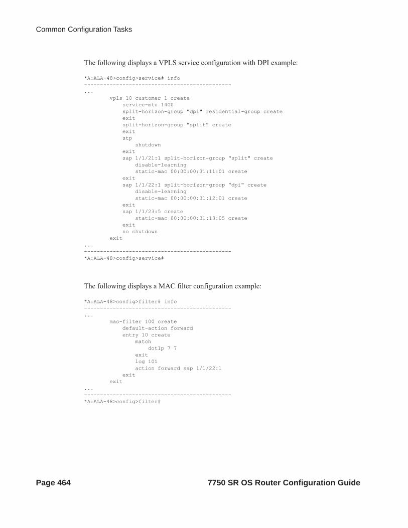
Common Configuration Tasks
The following displays a VPLS service configuration with DPI example:
*A:ALA-48>config>service# info----------------------------------------------... vpls 10 customer 1 create service-mtu 1400 split-horizon-group "dpi" residential-group create exit split-horizon-group "split" create exit stp shutdown exit sap 1/1/21:1 split-horizon-group "split" create disable-learning static-mac 00:00:00:31:11:01 create exit sap 1/1/22:1 split-horizon-group "dpi" create disable-learning static-mac 00:00:00:31:12:01 create exit sap 1/1/23:5 create static-mac 00:00:00:31:13:05 create exit no shutdown exit...----------------------------------------------*A:ALA-48>config>service#
The following displays a MAC filter configuration example:
*A:ALA-48>config>filter# info----------------------------------------------... mac-filter 100 create default-action forward entry 10 create match dot1p 7 7 exit log 101 action forward sap 1/1/22:1 exit exit...----------------------------------------------*A:ALA-48>config>filter#
Page 464 7750 SR OS Router Configuration Guide

Filter Policies
The following displays the MAC filter added to the VPLS service configuration:
*A:ALA-48>config>service# info----------------------------------------------... vpls 10 customer 1 create service-mtu 1400 split-horizon-group "dpi" residential-group create exit split-horizon-group "split" create exit stp shutdown exit sap 1/1/5:5 split-horizon-group "split" create ingress filter mac 100 exit static-mac 00:00:00:31:15:05 create exit sap 1/1/21:1 split-horizon-group "split" create disable-learning static-mac 00:00:00:31:11:01 create exit sap 1/1/22:1 split-horizon-group "dpi" create disable-learning static-mac 00:00:00:31:12:01 create exit sap 1/1/23:5 create static-mac 00:00:00:31:13:05 create exit spoke-sdp 3:5 create exit no shutdown exit....----------------------------------------------*A:ALA-48>config>service#
7750 SR OS Router Configuration Guide Page 465

Filter Management Tasks
Filter Management TasksThis section discusses the following filter policy management tasks:
• Renumbering Filter Policy Entries on page 466• Modifying a Filter Policy on page 468• Deleting a Filter Policy on page 470• Modifying a Redirect Policy on page 471• Deleting a Redirect Policy on page 472• Copying Filter Policies on page 473
Renumbering Filter Policy Entries
The system exits the matching process when the first match is found and then executes the actions in accordance with the specified action. Because the ordering of entries is important, the numbering sequence may need to be rearranged. Entries should be numbered from the most explicit to the least explicit.
The following example illustrates renumbering of filter entries.
Example: config>filter>ip-filter# renum 10 15config>filter>ip-filter# renum 20 10config>filter>ip-filter# renum 40 1
The following displays the original filter entry order on the left side and the reordered filter entries on the right side:
Page 466 7750 SR OS Router Configuration Guide

Filter Policies
A:ALA-7>config>filter# info----------------------------------------------... ip-filter 11 create description "filter-main" scope exclusive entry 10 create description "no-91" filter-sample interface-disable-sample match dst-ip 10.10.10.91/24 src-ip 10.10.10.103/24 exit action forward redirect-policy redirect1 exit entry 20 create match dst-ip 10.10.10.91/24 src-ip 10.10.0.100/24 exit action drop exit entry 30 create match dst-ip 10.10.10.91/24 src-ip 10.10.0.200/24 exit action forward exit entry 40 create match dst-ip 10.10.10.91/24 src-ip 10.10.10.106/24 exit action drop exit exit...----------------------------------------------A:ALA-7>config>filter#
A:ALA-7>config>filter# info----------------------------------------------... ip-filter 11 create description "filter-main" scope exclusive entry 1 create match dst-ip 10.10.10.91/24 src-ip 10.10.10.106/24 exit action drop exit entry 10 create match dst-ip 10.10.10.91/24 src-ip 10.10.0.100/24 exit action drop exit entry 15 create description "no-91" filter-sample interface-disable-sample match dst-ip 10.10.10.91/24 src-ip 10.10.10.103/24 exit action forward redirect-policy
redirect1 exit entry 30 create match dst-ip 10.10.10.91/24 src-ip 10.10.0.200/24 exit action forward exit exit...----------------------------------------------A:ALA-7>config>filter#
7750 SR OS Router Configuration Guide Page 467
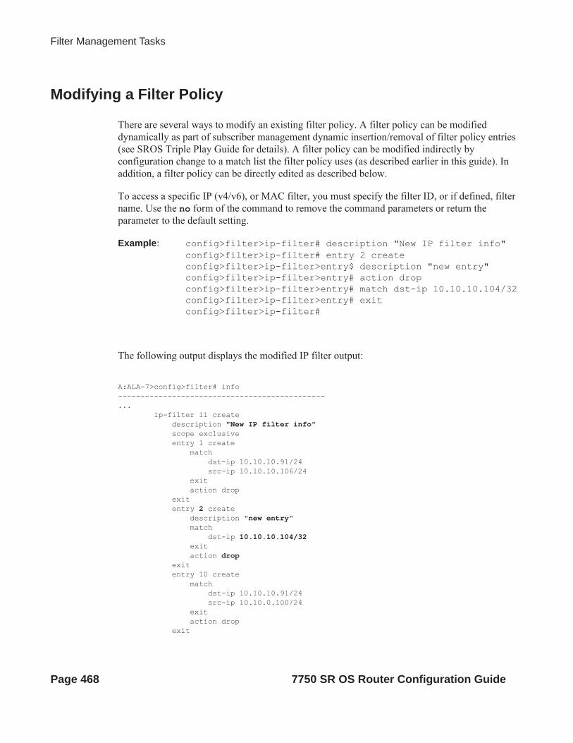
Filter Management Tasks
Modifying a Filter Policy
There are several ways to modify an existing filter policy. A filter policy can be modified dynamically as part of subscriber management dynamic insertion/removal of filter policy entries (see SROS Triple Play Guide for details). A filter policy can be modified indirectly by configuration change to a match list the filter policy uses (as described earlier in this guide). In addition, a filter policy can be directly edited as described below.
To access a specific IP (v4/v6), or MAC filter, you must specify the filter ID, or if defined, filter name. Use the no form of the command to remove the command parameters or return the parameter to the default setting.
Example: config>filter>ip-filter# description "New IP filter info"config>filter>ip-filter# entry 2 createconfig>filter>ip-filter>entry$ description "new entry"config>filter>ip-filter>entry# action dropconfig>filter>ip-filter>entry# match dst-ip 10.10.10.104/32config>filter>ip-filter>entry# exitconfig>filter>ip-filter#
The following output displays the modified IP filter output:
A:ALA-7>config>filter# info----------------------------------------------... ip-filter 11 create description "New IP filter info" scope exclusive entry 1 create match dst-ip 10.10.10.91/24 src-ip 10.10.10.106/24 exit action drop exit entry 2 create description "new entry" match dst-ip 10.10.10.104/32 exit action drop exit entry 10 create match dst-ip 10.10.10.91/24 src-ip 10.10.0.100/24 exit action drop exit
Page 468 7750 SR OS Router Configuration Guide

Filter Policies
entry 15 create description "no-91" match dst-ip 10.10.10.91/24 src-ip 10.10.10.103/24 exit action forward exit entry 30 create match dst-ip 10.10.10.91/24 src-ip 10.10.0.200/24 exit action forward exit exit..----------------------------------------------A:ALA-7>config>filter#
7750 SR OS Router Configuration Guide Page 469

Filter Management Tasks
Deleting a Filter Policy
Before you can delete a filter, you must remove the filter association from all the applied ingress and egress SAPs and network interfaces by executing no filter command in all context where the filter is used.
The following illustrates an example of removing a filter (filter ID 11) from an ingress ePipe SAP:
Example: config>service# epipe 5 config>service>epipe# sap 1/1/2:3 config>service>epipe>sap# ingress config>service>epipe>sap>ingress# no filter
After you have removed the filter from the SAPs network interfaces, you can delete the filter as shown in the following example.
Example: config>filter# no ip-filter 11
Page 470 7750 SR OS Router Configuration Guide

Filter Policies
Modifying a Redirect Policy
To access a specific redirect policy, you must specify the policy name. Use the no form of the command to remove the command parameters or return the parameter to the default setting.
Example: config>filter# redirect-policy redirect1config>filter>redirect-policy# description "New redirect info"config>filter>redirect-policy# destination 10.10.10.106config>filter>redirect-policy>dest# no url-test "URL_to_106"config>filter>redirect-policy>dest# url-test "URL_to_Proxy"config>filter>redirect-policy>dest>url-test$ url http://
www.alcatel.comconfig>filter>redirect-policy>dest>url-test# interval 10config>filter>redirect-policy>dest>url-test# timeout 10config>filter>redirect-policy>dest>url-test# return-code 1
4294967295 raise-priority 255
A:ALA-7>config>filter# info----------------------------------------------... redirect-policy "redirect1" create description "New redirect info" destination 10.10.10.104 create description "SNMP_to_104" priority 105 snmp-test "SNMP-1" interval 30 drop-count 30 hold-down 120 exit no shutdown exit destination 10.10.10.105 create priority 95 ping-test timeout 30 drop-count 5 exit no shutdown exit destination 10.10.10.106 create priority 90 url-test "URL_to_Proxy" url "http://www.alcatel.com" interval 10 timeout 10 return-code 1 4294967295 raise-priority 255 exit no shutdown exit no shutdown exit...----------------------------------------------A:ALA-7>config>filter#
7750 SR OS Router Configuration Guide Page 471

Filter Management Tasks
Deleting a Redirect Policy
Before you can delete a redirect policy from the filter configuration, you must remove the policy association from the IP filter.
The following example shows the command usage to replace the configured redirect policy (redirect1) with a different redirect policy (redirect2) and then removing the redirect1 policy from the filter configuration.
Example:config>filter>ip-filter 11config>filter>ip-filter# entry 1config>filter>ip-filter>entry# action forward redirect-policy
redirect2config>filter>ip-filter>entry# exitconfig>filter>ip-filter# exitconfig>filter# no redirect-policy redirect1
A:ALA-7>config>filter>ip-filter# info---------------------------------------------- description "This is new" scope exclusive entry 1 create
filter-sampleinterface-disable-sample
match dst-ip 10.10.10.91/24 src-ip 10.10.10.106/24 exit action forward redirect-policy redirect2 exit entry 2 create description "new entry"...----------------------------------------------A:ALA-7>config>filter>ip-filter#
Page 472 7750 SR OS Router Configuration Guide

Filter Policies
Copying Filter Policies
When changes are to be made to an existing filter policy applied to a one or more SAPs/network interfaces, it is recommended to first copy the applied filter policy, then modify the copy and then overwrite the applied policy with the modified copy. This ensures that a policy being modified is not applied when partial changes are done as any filter policy edits are applied immediately to all services where the policy is applied.
New filter policies can also be created by copying an existing policy and renaming the new filter.
The following displays the command usage to copy an existing IP filter (11) to create a new filter policy (12) that can then be edited. And once edits are completed, it can be used to overwrite existing policy (11).
Example: config>filter# copy ip-filter 11 to 12
A:ALA-7>config>filter# info----------------------------------------------... ip-filter 11 create description "This is new" scope exclusive entry 1 create match dst-ip 10.10.10.91/24 src-ip 10.10.10.106/24 exit action drop exit entry 2 create... ip-filter 12 create description "This is new" scope exclusive entry 1 create match dst-ip 10.10.10.91/24 src-ip 10.10.10.106/24 exit action drop exit entry 2 create...----------------------------------------------A:ALA-7>config>filter#
7750 SR OS Router Configuration Guide Page 473

Filter Management Tasks
Page 474 7750 SR OS Router Configuration Guide

Filter Policies
Filter Command Reference
Command Hierarchies• DHCP Filter Policy Commands on page 475
• Match Filter List Commands on page 481
• IP Filter Policy Commands on page 476
• IPv6 Filter Policy Commands on page 478
• Log Filter Commands on page 479
• MAC Filter Commands on page 480
• Redirect Policy Configuration Commands on page 482
• Copy Filter Commands on page 483
• Show Commands on page 483
• Clear Commands on page 483
• Monitor Commands on page 484
Configuration Commands
DHCP Filter Policy Commandsconfig
— filter— dhcp-filter filter-id [create]— no dhcp-filter filter-id
— description description-string— no description— entry entry-id [create] — no entry entry-id
— action {bypass-host-creation}— action drop— no action— option dhcp-option-number {present | absent}— option dhcp-option-number match hex hex-string [exact] [invert-
match]— option dhcp-option-number match string ascii-string [exact] [invert-
match]— no option
7750 SR OS Router Configuration Guide Page 475

Filter Command Reference
IP Filter Policy Commandsconfig
— filter— ip-filter filter-id [create]— ip-filter {filter-id | filter-name}— no ip-filter filter-id
— default-action {drop | forward}— description description-string— no description— embed-filter {filter-id | open-flow ofs-name} [offset offset ] [{active | inactive}]— no embed-filter {filter-id}— entry entry-id [time-range time-range-name] [create] — no entry entry-id
— action [drop]— action drop packet-length {{lt | gt | eq} packet-length-value} | {range
packet-length-value packet-length-value}— action forward— action forward next-hop {ip-address|indirect ip-address|interface ip-
int-name}— action forward [redirect-policy policy-name]— action forward {sap sap-id|sdp sdp-id:vc-id}— action http-redirect rdr-url-string [allow-radius-override]— action forward lsp lsp-name— action forward router {router-instance | service-name service-name}— action gtp-local-breakout— action nat [nat-policy nat-policy-name]— action reassemble— action forward [sap sap-id|sdp sdp-id:vc-id]— no action— description description-string— no description— [no] filter-sample— [no] interface-disable-sample— log log-id— no log— match [protocol protocol-id]— no match
— dscp dscp-name — no dscp— dst-ip {ip-address/mask | ip-address ipv4-address-mask | ip-
prefix-list prefix-list-name}— no dst-ip— dst-port {lt | gt | eq} dst-port-number — dst-port port-list-name— dst-port range dst-port-number dst-port-number— no dst-port— fragment {true|false|first-only|non-first-only}— no fragment— icmp-code icmp-code — no icmp-code — icmp-type icmp-type — no icmp-type — ip-option ip-option-value [ip-option-mask]— no ip-option— multiple-option {true | false}— no multiple-option
Page 476 7750 SR OS Router Configuration Guide

Filter Policies
— option-present {true | false}— no option-present— port {lt|gt|eq} port-number — port port-list port-list-name— port range port-number port-number— no port— src-ip{ip-address/mask | ip-address ipv4-address-mask | ip-
prefix-list prefix-list-name}— no src-ip— src-port {{lt | gt | eq} src-port-number} — src-port port-list port-list-name— src-port range src-port-number src-port-number— no src-port— src-route-option {true|false}— no src-route-option — tcp-ack {true | false}— no tcp-ack— tcp-syn {true | false}— no tcp-syn
— filter-name filter-name— no filter-name— renum old-entry-id new-entry-id— scope {exclusive | template | embedded}— no scope— shared-radius-filter-wmark low low-watermark high high-watermark— no shared-radius-filter-wmark— sub-insert-credit-control start-entry entry-id count count— no sub-insert-credit-control— sub-insert-radius start-entry entry-id count count— no sub-insert-radius— sub-insert-shared-radius start-entry entry-id count count— no sub-insert-shared-radius— sub-insert-wmark low low-watermark high high-watermark— no sub-insert-wmark
7750 SR OS Router Configuration Guide Page 477

Filter Command Reference
IPv6 Filter Policy Commands
—IPv6 Filter Policy Commands config— filter
— ipv6-filter filter-id [create]— ipv6-filter {filter-id | filter-name}— no ipv6-filter filter-id
— default-action {drop | forward}— description description-string— no description— embed-filter {filter-id | open-flow ofs-name} [offset offset ] [{active | inactive}]— no embed-filter {filter-id | open-flow ofs-name}— entry entry-id [time-range time-range-name] [create] — no entry entry-id
— action [drop]— action drop packet-length {{lt | eq | gt} packet-length-value | range
packet-length-value packet-length-value}— action forward— action forward next-hop {ipv6-address|indirect ipv6-address}— action forward [lsp lsp-name] — action forward {sap sap-id|sdp sdp-id:vc-id}— action forward router{router-instance service-name service-name}— action http-redirect rdr-url-string [allow-radius-override]— action nat nat-type nat-type [nat-policy nat-policy-name]— no action— description description-string— no description— [no] filter-sample— [no] interface-disable-sample— log log-id— no log— match [next-header next-header]— no match
— ah-ext-hdr {true | false }— no ah-ext-hdr— dscp dscp-name — no dscp— dst-ip {ipv6-address/prefix-length | ipv6-address ipv6-
address-mask | ipv6-prefix-list prefix-list-name}— no dst-ip— dst-port {lt | gt | eq} dst-port-number — dst-port port-list port-list-name — dst-port range dst-port-number dst-port-number— no dst-port— esp-ext-hdr {true | false }— no esp-ext-hdr— flow-label flow-label [mask] — no flow-label— fragment {true|false|first-only|non-first-only}— no fragment— hop-by-hop-opt {true|false}— no hop-by-hop-opt— icmp-code icmp-code — no icmp-code — icmp-type icmp-type — no icmp-type
Page 478 7750 SR OS Router Configuration Guide

Filter Policies
— port {lt|gt|eq} port-number — port port-list port-list-name— port range port-number port-number— no port — routing-type0 {true|false}— no routing-type0— src-ip{ipv6-address/prefix-length | ipv6-address ipv6-address-
mask | ipv6-prefix-list prefix-list-name}— no src-ip— src-port {lt | gt | eq} src-port-number}— src-port port-list port-list-name— src-port range src-port-number src-port-number— no src-port— tcp-ack {true | false}— no tcp-ack— tcp-syn {true | false}— no tcp-syn
— filter-name filter-name— no filter-name— group-inserted-entries application application location location— renum old-entry-id new-entry-id— scope {exclusive | template | embedded}— no scope— shared-radius-filter-wmark low low-watermark high high-watermark— no shared-radius-filter-wmark— sub-insert-credit-control start-entry entry-id count count— no sub-insert-credit-control— sub-insert-radius start-entry entry-id count count— no sub-insert-radius— sub-insert-shared-radius start-entry entry-id count count— no sub-insert-shared-radius— sub-insert-wmark low low-watermark high high-watermark— no sub-insert-wmark
Log Filter Commandsconfig
— filter— log log-id [create]— no log log-id
— description description-string— no description— destination memory num-entries | syslog syslog-id— no destination— [no] shutdown— summary
— [no] shutdown— summary-crit dst-addr— summary-crit src-addr— no summary-crit
— [no] wrap-around
7750 SR OS Router Configuration Guide Page 479

Filter Command Reference
MAC Filter Commandsconfig
— filter— mac-filter filter-id [create]— mac-filter {filter-id | filter-name}— no mac-filter filter-id
— default-action {drop | forward}— description description-string— no description— entry entry-id [time-range time-range-name]— no entry entry-id [create]
— action [drop]— action forward {sap sap-id | sdp sdp-id | vc-id}— no action— description description-string— no description— log log-id— no log— match [frame-type {802dot3 | 802dot2-llc | 802dot2-snap |
ethernet_II}]— no match
— dot1p dot1p-value [dot1p-mask]— no dot1p— dsap dsap-value [dsap-mask]— no dsap— dst-mac ieee-address [ieee-address-mask]— no dst-mac— etype 0x0600..0xffff— no etype— inner-tag value [vid-mask]— no inner-tag— isid value [to higher-value]— no isid— outer-tag value [vid-mask]— no outer-tag— snap-oui {zero | non-zero}— no snap-oui— snap-pid snap-pid— no snap-pid— ssap ssap-value [ssap-mask]— no ssap— src-mac ieee-address [ieee-address-mask]— no src-mac
— renum old-entry-id new-entry-id— scope {exclusive | template}— no scope— type filter-type
Page 480 7750 SR OS Router Configuration Guide

Filter Policies
Match Filter List Commandsconfig
— filter— match-list
— ip-prefix-list ip-prefix-list-name [create]— no ip-prefix-list ip-prefix-list-name
— [no] apply-path— bgp-peers index group reg-exp neighbor reg-exp— no bgp-peers index
— description description-string— no description— [no] prefix ip-prefix/prefix-length
— ipv6-prefix-list ipv6-prefix-list-name [create]— no ipv6-prefix-list ipv6-prefix-list-name
— [no] apply-path— bgp-peers index group reg-exp neighbor reg-exp— no bgp-peers index
— description description-string— no description— [no] prefix ipv6-prefix/prefix-length
— port-list port-list-name create— no port-list port-list-name
— description description-string— no description— [no] port port number— [no] port range start end— no port
7750 SR OS Router Configuration Guide Page 481

Filter Command Reference
Redirect Policy Configuration Commandsconfig
— filter—Redirect policy commands — redirect-policy redirect-policy-name [create]
— no redirect-policy redirect-policy-name— description description-string— no description— destination ip-address [create]— no destination ip-address
— description description-string— no description— [no] ping-test
— drop-count consecutive-failures [hold-down seconds]— no drop-count— interval seconds— no interval— timeout seconds— no timeout
— priority [priority]— no priority— [no] shutdown— snmp-test test-name [create]— no snmp-test test-name
— drop-count consecutive-failures [hold-down seconds]— no drop-count— interval seconds— no interval— oid oid-string community community-string— no oid— return-value return-value type return-type [disable | lower-
priority priority | raise-priority priority]— no return-value return-value type return-type— timeout seconds— no timeout
— url-test test-name [create]— no url-test test-name
— drop-count consecutive-failures [hold-down seconds]— no drop-count— interval seconds— no interval— return-code return-code-1 [return-code-2] [disable | lower-
priority priority | raise-priority priority]— no return-code return-code-1 [return-code-2]— timeout seconds— no timeout— url url-string [http-version version-string]— no url
— [no] shutdown
Page 482 7750 SR OS Router Configuration Guide

Filter Policies
Copy Filter Commandsconfig
— filter— copy ip-filter src-filter-id [src-entry src-entry-id] to dst-filter-id [dst-entry dst-entry-id]
[overwrite]— copy ipv6-filter src-filter-id [src-entry src-entry-id] to dst-filter-id [dst-entry dst-entry-id]
[overwrite]— copy mac-filter src-filter-id [src-entry src-entry-id] to dst-filter-id [dst-entry dst-entry-id]
[overwrite]
Show Commandsshow
— filter— dhcp [filter-id]— download-failed— ip [filter-type filter-type]— ip embedded [inactive]— ip ip-filter-id embedded [inactive]— ip ip-filter-id [detail]— ip ip-filter-id associations— ip ip-filter-id type entry-type— ip ip-filter-id counters [type entry-type]— ip ip-filter-id entry entry-id counters— ip ip-filter-id entry entry-id [detail]— ipv6 [filter-type filter-type]— ipv6 embedded [inactive]— ipv6 ipv6-filter-id embedded [inactive]— ipv6 ipv6-filter-id [detail]— ipv6 ipv6-filter-id associations— ipv6 ipv6-filter-id type entry-type— ipv6 ipv6-filter-id counters [type entry-type]— ipv6 ipv6-filter-id entry entry-id counters— ipv6 ipv6-filter-id entry entry-id [detail]— log [bindings]— log log-id [match string]— mac {mac-filter-id [entry entry-id] [association | counters]}— match-list
— ip-prefix-list [prefix-list-name]— ip-prefix-list prefix-list-name references— ipv6-prefix-list [prefix-list-name]— ipv6-prefix-list prefix-list-name references— port-list [port-list-name]— port-list port-list-name references
— redirect-policy {redirect-policy-name [dest ip-address] [association]}
Clear Commandsclear
— filter— ip filter-id [entry entry-id] [ingress | egress]— ipv6 filter-id [entry entry-id] [ingress | egress]— log log-id— mac filter-id [entry entry-id] [ingress | egress]
7750 SR OS Router Configuration Guide Page 483

Filter Command Reference
Monitor Commandsmonitor
— filter ip ip-filter-id entry entry-id [interval seconds] [repeat repeat] [absolute | rate]— filter ipv6 ipv6-filter-id entry entry-id [interval seconds] [repeat repeat] [absolute | rate]— filter mac mac-filter-id entry entry-id [interval seconds] [repeat repeat] [absolute | rate]
Page 484 7750 SR OS Router Configuration Guide

Filter Policies
Configuration Commands
Generic Commands
description
Syntax description stringno description
Context config>filter>dhcp-filterconfig>filter>ip-filterconfig>filter>ipv6-filterconfig>filter>ip-filter>entryconfig>filter>ip-filter>entryconfig>filter>ipv6-filter>entryconfig>filter>log config>filter>mac-filterconfig>filter>mac-filter>entryconfig>filter>redirect-policyconfig>filter>redirect-policy>destinationconfig>filter>match-list>ip-prefix-listconfig>filter>match-list>ip-filterconfig>filter>match-list>port-list
Description This command creates a text description stored in the configuration file for a configuration context.
The description command associates a text string with a configuration context to help identify the context in the configuration file.
The no form of the command removes any description string from the context.
Default none
Parameters string — The description character string. Allowed values are any string up to 80 characters long composed of printable, 7-bit ASCII characters. If the string contains special characters (#, $, spaces, etc.), the entire string must be enclosed within double quotes.
7750 SR OS Router Configuration Guide Page 485
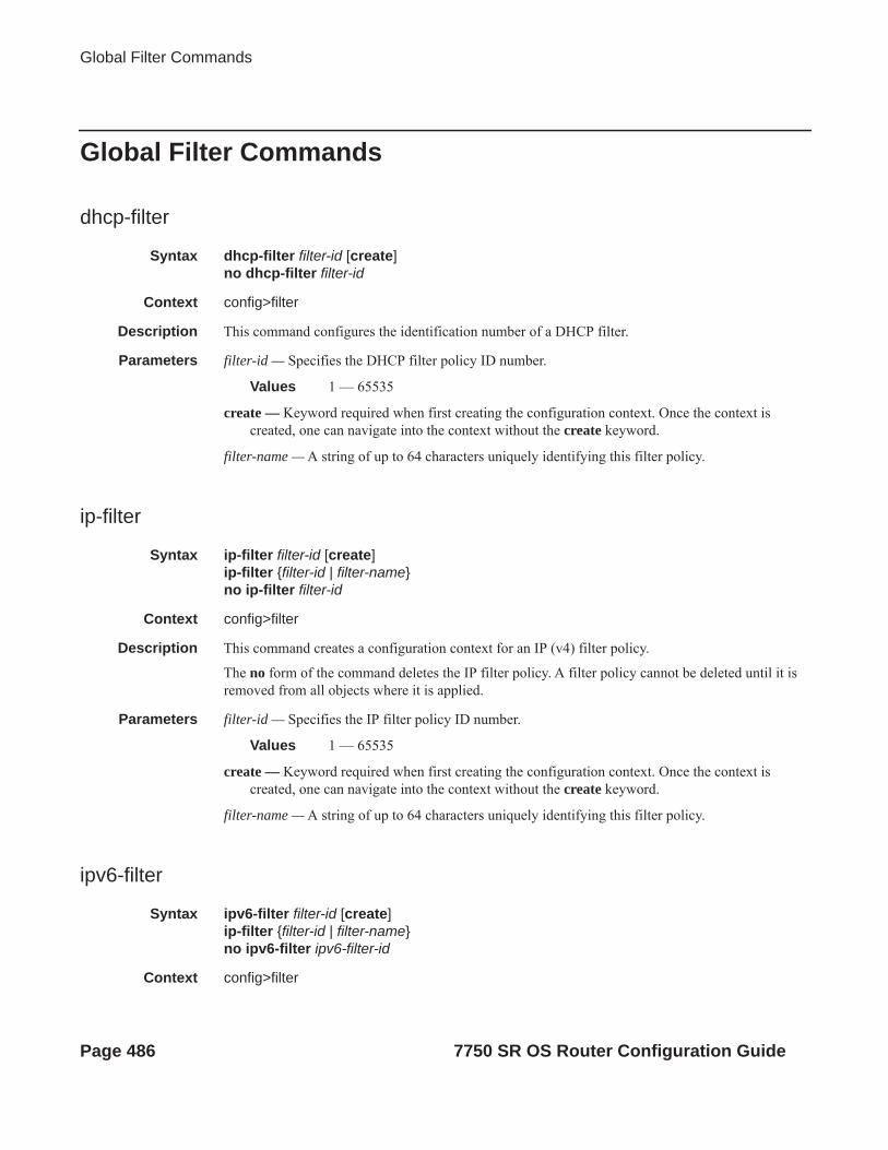
Global Filter Commands
Global Filter Commands
dhcp-filter
Syntax dhcp-filter filter-id [create]no dhcp-filter filter-id
Context config>filter
Description This command configures the identification number of a DHCP filter.
Parameters filter-id — Specifies the DHCP filter policy ID number.
Values 1 — 65535
create — Keyword required when first creating the configuration context. Once the context is created, one can navigate into the context without the create keyword.
filter-name — A string of up to 64 characters uniquely identifying this filter policy.
ip-filter
Syntax ip-filter filter-id [create]ip-filter {filter-id | filter-name}no ip-filter filter-id
Context config>filter
Description This command creates a configuration context for an IP (v4) filter policy.
The no form of the command deletes the IP filter policy. A filter policy cannot be deleted until it is removed from all objects where it is applied.
Parameters filter-id — Specifies the IP filter policy ID number.
Values 1 — 65535
create — Keyword required when first creating the configuration context. Once the context is created, one can navigate into the context without the create keyword.
filter-name — A string of up to 64 characters uniquely identifying this filter policy.
ipv6-filter
Syntax ipv6-filter filter-id [create]ip-filter {filter-id | filter-name}no ipv6-filter ipv6-filter-id
Context config>filter
Page 486 7750 SR OS Router Configuration Guide

Filter Policies
Description This command creates a configuration context for an IP (v6) filter policy.
The no form of the command deletes the IP filter policy. A filter policy cannot be deleted until it is removed from all objects where it is applied.
Parameters filter-id — specifies the IPv6 filter policy ID number.
Values 1 — 65535
create — Keyword required when first creating the configuration context. Once the context is created, one can navigate into the context without the create keyword.
filter-name — A string of up to 64 characters uniquely identifying this IPv6 filter policy.
mac-filter
Syntax mac-filter filter-id [create]mac-filter {filter-id | filter-name}no mac-filter filter-id
Context config>filter
Description This command enables the context for a MAC filter policy.
The no form of the command deletes the mac-filter policy. A filter policy cannot be deleted until it is removed from all objects where it is applied.
Parameters filter-id — The MAC filter policy ID number.
Values 1 — 65535
create — Keyword required when first creating the configuration context. Once the context is created, one can navigate into the context without the create keyword.
filter-name — A string of up to 64 characters uniquely identifying this filter policy.
redirect-policy
Syntax [no] redirect-policy redirect-policy-name
Context config>filter
Description This command configures redirect policies.
The no form of the command removes the redirect policy from the filter configuration only if the policy is not referenced in a filter and the filter is not in use (applied to a service or network interface).
Default none
Parameters redirect-policy-name — Specifies the redirect policy name. Allowed values are any string up to 32 characters long composed of printable, 7-bit ASCII characters. If the string contains special characters (#, $, spaces, etc.), the entire string must be enclosed within double quotes. There is no limit to the number of redirect policies that can be configured.
7750 SR OS Router Configuration Guide Page 487

Global Filter Commands
log
Syntax log log-id [create]no log
Context config>filter
Description This command enables the context to create a filter log policy.
The no form of the command deletes the filter log ID. The log cannot be deleted if there are filter entries configured to write to the log. All filter entry logging associations need to be removed before the log can be deleted.
Special Cases Filter log 101 — Filter log 101 is the default log and is automatically created by the system. Filter log 101 is always a memory filter log and cannot be changed to a Syslog filter log. The log size defaults to 1000 entries. The number of entries and wrap-around behavior can be modified.
Default log 101
Parameters log-id — The filter log ID destination expressed as a decimal integer.
Values 101 — 199
Page 488 7750 SR OS Router Configuration Guide

Filter Policies
DHCP Filter Commands
action
Syntax action {bypass-host-creation}action dropno action
Context config>filter>dhcp-filter>entry
Description This command specifies the action to take on DHCP host creation when the filter entry matches.
The no form of the command reverts to the default wherein the host creation proceeds as normal
Default no action
Parameters bypass-host-creation — Specifies that the host creation is bypassed.
drop — Specifies the DHCP message is dropped.
option
Syntax option dhcp-option-number {present | absent}option dhcp-option-number match hex hex-string [exact] [invert-match]option dhcp-option-number match string ascii-string [exact] [invert-match]no option
Context config>filter>dhcp-filter>entry
Description This command configures the action to take on DHCP host creation when the filter entry matches.
The no form of the command reverts to the default.
Parameters dhcp-option-number —
Values 0 — 255
present — Specifies that the related DHCP option must be present.
absent — Specifies that the related DHCP option must be absent.
match hex hex-string — The option must (partially) match a specified hex string.
Values 0x0..0xFFFFFFFF...(max 254 hex nibbles)
match string ascii-string — The option must (partially) match a specified ASCII string.
Values Up to 127 characters
exact — This option requires an exact match of a hex or ascii string.
invert-match — Requires the option not to (partially) match.
7750 SR OS Router Configuration Guide Page 489

Filter Log Commands
Filter Log Commands
destination
Syntax destination memory num-entriesdestination syslog syslog-idno destination
Context config>filter>log
Description This command configures the destination for filter log entries for the filter log ID.
Filter logs can be sent to either memory (memory) or to an existing Syslog server definition (syslog).
If the filter log destination is memory, the maximum number of entries in the log must be specified.
The no form of the command deletes the filter log association.
Default no destination
Parameters memory num-entries — Specifies the destination of the filter log ID is a memory log. The num-entries value is the maximum number of entries in the filter log expressed as a decimal integer.
Values 10 — 50000
syslog syslog-id — Specifies the destination of the filter log ID is a Syslog server. The syslog-id parameter is the number of the Syslog server definition.
Values 1 — 10
shutdown
Syntax [no] shutdown
Context config>filter>logconfig>filter>log>summary
Administratively enables/disabled (AdminUp/AdminDown) an entity. Downing an entity does not change, reset or remove any configuration settings or statistics. Many objects must be shutdown before they may be deleted.
The shutdown command administratively downs an entity. Administratively downing an entity changes the operational state of the entity to down.
Unlike other commands and parameters where the default state will not be indicated in the configuration file, shutdown and no shutdown are always indicated in system generated configuration files.
The no form of the command puts an entity into the administratively enabled state.
Default no shutdown
Page 490 7750 SR OS Router Configuration Guide

Filter Policies
summary
Syntax summary
Context config>filter>log
Description This command enables the context to configure log summarization. These settings will only be taken into account when syslog is the log destination. Note that summary settings will only be taken into account in case the log destination is syslog.
Parameters none
summary-crit
Syntax summary-crit dst-addrsummary-crit src-addrno summary-crit
Context config>filter>log>summary
Description This command defines the the key of the index of the minitable. If key information is changed while summary is in no shutdown, the filter summary minitable is flushed and recreated with different key information. Log packets received during the reconfiguration time will be handled as if summary was not active.
The no form of the command reverts to the default parameter.
Default dst-addr
Parameters dst-addr — Specifies that received log packets are summarized based on the destination IP, IPv6, or MAC address.
src-addr — Specifies that received log packets are summarized based on the source IP, IPv6 or MAC address.
wrap-around
Syntax [no] wrap-around
Context config>filter>log
Description This command configures a memory filter log to log until full or to store the most recent log entries (circular buffer).
Specifying wrap-around configures the memory filter log to store the most recent filter log entries (circular buffer). When the log is full, the oldest filter log entries are overwritten with new entries.
The no form of the command configures the memory filter log to accept filter log entries until full. When the memory filter log is full, filter logging for the log filter ID ceases.
Default wrap-around
7750 SR OS Router Configuration Guide Page 491

ACL Filter Policy Commands
ACL Filter Policy Commands
default-action
Syntax default-action {drop | forward}
Context config>filter>ip-filterconfig>filter>ipv6-filterconfig>filter>mac-filter
Description This command defines default action to be applied to packets for this filter policy.
Default drop
Parameters drop — Specifies all packets will be dropped unless there is a filter entry which causes the packet to be forwarded.
forward — Specifies all packets will be forwarded unless there is a filter entry which causes the packet to be dropped.
embed-filter
Syntax embed-filter filter-id [offset offset] [{active | inactive} embed-filter open-flow ofs-name [ offset offset] [{ active | inactive}]]no embed-filter {filter-id | open-flow ofs-name}
Context config>filter>ip-filterconfig>filter>ipv6-filter
Description This command embeds a previously defined IPv4, or IPv6 embedded filter policy or a Hybrid OpenFlow switch instanceinto this exclusive or template filter policy at the specified offset value.
active | inactive keywords:
active – an embedded filter entries are to be included in this embedding filter policy and activated on applicable line cards – default if no keyword is specified and omitted in info command (but not info detail), or when saving configuration
inactive – an embedded filter policy entries are to be included in this embedded filter policy but are not downloaded to line cards – i.e. remain inactive. Always shown as part of info command or when saved to a configuration file.
The no form of this command removes the embeding from this filter policy.
Please see the description of embedded filter policies in this guide for further operational details.
Default No embedded filter policies are included in a filter policy by default
Parameters filter-id — Specifies a previously defined embedded filter policy.
ofs-name — name of the currently configured Hybrid OpenFlow switch instance
Page 492 7750 SR OS Router Configuration Guide

Filter Policies
offset — a value from 0 to 65535, an embedded filter entry X will have an entry X + offset in the embedding filter.
filter-name
Syntax filter-name filter-name
Context config>filter>ip-filterconfig>filter>ipv6>filterconfig>filter>mac-filter
Description This command configures filter-name attribute of a given filter. filter-name, when configured, can be used instead of filter ID to reference the given policy in the CLI.
Default no filter-name
Parameters filter-name — A string of up to 64 characters uniquely identifying this filter policy.
scope
Syntax scope {exclusive | template | embedded}no scope
Context config>filter>ip-filterconfig>filter>ipv6-filterconfig>filter>mac-filter
Description This command configures the filter policy scope as exclusive, template, or embedded. If the scope of the policy is template and is applied to one or more services or network interfaces, the scope cannot be changed.
The no form of the command sets the scope of the policy to the default of template.
Default template
Parameters exclusive — When the scope of a policy is defined as exclusive, the policy can only be applied to a single entity (SAP or network port). Attempting to assign the policy to a second entity will result in an error message. If the policy is removed from the entity, it will become available for assignment to another entity.
template — When the scope of a policy is defined as template, the policy can be applied to multiple SAPs or network ports.
embedded — When the scope of a policy is defined as embedded, the policy cannot be applied directly to SAP/interface. The policy defines embedded filter rules, which can be embedded by other filter policies. embedded scope is supported for IP and IPv6 filter policies only.
7750 SR OS Router Configuration Guide Page 493

ACL Filter Policy Commands
shared-radius-filter-wmark
Syntax shared-radius-filter-wmark low low-watermark high high-watermarkno shared-radius-filter-wmark
Context config>filter>ip-filterconfig>filter>ipv6-filter
Description This command configures the low and high watermark for the number of RADIUS shared filters reporting
Parameters low low-watermark — Specifies the utilization of the filter ranges for filter entry insertion, at which a table full alarm will be raised by the agent.
Values 0 — 8000
high high-watermark — Specifies the utilization of the filter ranges for filter entry insertion, at which a table full alarm will be cleared by the agent.
Values 1— 8000
sub-insert-credit-control
Syntax sub-insert-credit-control start-entry entry-id count countno sub-insert-credit-control
Context config>filter>ip-filterconfig>filter>ipv6-filter
Description This command inserts point information for credit control for the filter.
The no form of the command reverts to the default.
Default none
Parameters entry entry-id — Identifies a filter on this system.
Values 1 — 65535
count count — Specifies the count.
Values 1 — 65535
sub-insert-radius
Syntax sub-insert-radius start-entry entry-id count countno sub-insert-radius
Context config>filter>ip-filterconfig>filter>ipv6-filter
Description This command insert point information for RADIUS for the filter.
Page 494 7750 SR OS Router Configuration Guide

Filter Policies
The no form of the command reverts to the default.
Default none
Parameters entry entry-id — Specifies at what place the filter entries received from RADIUS will be inserted in the filter.
Values 1 — 65535
count count — Specifies the count.
Values 1 — 65535
sub-insert-shared-radius
Syntax sub-insert-shared-radius start-entry entry-id count countno sub-insert-shared-radius
Context config>filter>ip-filterconfig>filter>ipv6-filter
Description This command configures the insert point for shared host rules from RADIUS.
entry entry-id — Identifies a filter on this system.
Values 1 — 65535
count count — Specifies the count.
Values 1 — 65535
sub-insert-wmark
Syntax sub-insert-wmark low low-watermark high high-watermarkno sub-insert-wmark
Context config>filter>ip-filterconfig>filter>ipv6-filter
Description This command configures the low and high watermark percentage for inserted filter entry usage reporting.
The no form of the command reverts to the default.
Default none
Parameters low low-watermark — Specifies the utilization of the filter ranges for filter entry insertion, at which a table full alarm will be cleared by the agent.
Values 0 — 100
7750 SR OS Router Configuration Guide Page 495

ACL Filter Policy Commands
high high-watermark — Specifies the utilization of the filter ranges for filter entry insertion, at which a table full alarm will be raised by the agent.
Values 0 — 100
type
Syntax type filter-type
Context config>filter>mac-filter
Description This command configures the type of mac-filter as normal, ISID or VID types.
Default normal
Parameters filter-type — Specifies which type of entries this MAC filter can contain.
Values normal — Regular match criteria are allowed; ISID or VID filter match criteria not allowed.isid — Only ISID match criteria are allowed.vid — On.y VID match criteria are allowed on ethernet_II frame types.
Page 496 7750 SR OS Router Configuration Guide

Filter Policies
General Filter Entry Commands
entry
Syntax entry entry-id [time-range time-range-name] [create]no entry entry-id
Context config>filter>dhcp-filterconfig>filter>ip-filterconfig>filter>ipv6-filterconfig>filter>mac-filter
Description This command creates or edits an IP (v4), IPv6, or MAC filter entry. Multiple entries can be created using unique entry-id numbers within the filter. Entries must be sequenced from most to least explicit.
An entry may not have any match criteria defined (in which case, everything matches) but must have at least the keyword action for it to be considered complete. Entries without the action keyword will be considered incomplete and hence will be rendered inactive.
The no form of the command removes the specified entry from the filter. Entries removed from the filter are immidately removed from all services or network ports where that filter is applied.
Default none
Parameters entry-id — An entry-id uniquely identifies a match criteria and the corresponding action. It is recommended that multiple entries be given entry-ids in staggered increments. This allows users to insert a new entry in an existing policy without requiring renumbering of all the existing entries.
Values 1 — 65535
time-range time-range-name — Specifies the time range name to be associated with this filter entry up to 32 characters in length. The time-range name must already exist in the config>cron context.
create — Keyword required when first creating the configuration context. Once the context is created, one can navigate into the context without the create keyword.
log
Syntax log log-idno log
Context config>filter>ip-filter>entryconfig>filter>ipv6-filter>entryconfig>filter>mac-filter>entry
Description This command creates the context to enable filter logging for a filter entry and specifies the destination filter log ID.
The filter log ID must exist before a filter entry can be enabled to use the filter log ID.
7750 SR OS Router Configuration Guide Page 497

General Filter Entry Commands
The no form of the command disables logging for the filter entry.
Default no log
Parameters log-id — The filter log ID destination expressed as a decimal integer.
Values 101 — 199
Page 498 7750 SR OS Router Configuration Guide

Filter Policies
IP (v4/v6) Filter Entry Commands
action
Syntax For IPv4:action [drop]action forward [lsp lsp-name]action forwardaction drop packet-length {{lt | eq | gt} packet-length-value | range packet-length-value packet-length-value}action forward next-hop {ip-address|indirect ip-address|interface ip-int-name}action forward redirect-policy policy-nameaction forward {sap sap-id|sdp sdp-id:vc-id}action forward lsp lsp-nameaction gtp-local-breakoutaction nat [nat-policy nat-policy-name]action reassembleaction http-redirect rdr-url-string [allow-radius-override]no actionFor IPv6:action [drop]action forwardaction forward next-hop {ipv6-address|indirect ipv6-address}action forward lsp lsp-nameaction forward router {router-instance |service-name service-name}action forward {sap sap-id|sdp sdp-id:vc-id}action http-redirect rdr-url-string [allow-radius-override] action nat nat-type nat-type [nat-policy nat-policy-name]no action
Context config>filter>ip-filter>entryconfig>filter>ipv6-filter>entry
Description This command specifies the action to take for packets that match this filter entry. The action command must be entered with a keyword specified in order for the entry to be active.
The no form of the command removes the specified action statement.
Default no action
Parameters drop — Specifies packets matching the entry criteria will be dropped.
forward — Specifies packets matching the entry criteria will be forwarded.
next-hop ip-address — The IP address of the direct next-hop to which to forward matching packets in dotted decimal notation.
7750 SR OS Router Configuration Guide Page 499

IP (v4/v6) Filter Entry Commands
indirect ip-address — The IP address of the indirect next-hop to which to forward matching packets in dotted decimal notation. The direct next-hop IP address and egress IP interface are determined by a route table lookup.
If the next hop is not available, then a routing lookup will be performed and if a match is found the packet will be forwarded to the result of that lookup. If no match is found a "ICMP destination unreachable" message is send back to the origin.
redirect policy-name — Specifies the redirect policy configured in the config>filter>redirect-policy context.
packet-length {{lt | eq | gt} packet-length-value | range packet-length-value packet-length-value} — - Specifies packet matching an entry will be dropped if “Total Length” field in packet’s
IPv4 header matches the packet-length condition configured. Otherwise, the packet (packet matching entry condition but not packet-length condition) will be forwarded.
Operators: lt – “less than”, eq – “equal to”, gt – “greater than”, range - "specifies an inclusive range" can be used to specify action execution condition. Inclusive range can be defined using range operator.
Values packet-length-value – integers from 0 to 65535. 0 cannot be used with lt, and 65535 cannot be used with gt. When range is used, the start of the range (first value entered) must be smaller than the end of the range (second value entered).
interface ip-int-name — The name of the egress IP interface where matching packets will be forwarded from. This parameter is only valid for unnumbered point-to-point interfaces. If the string contains special characters (#, $, spaces, etc.), the entire string must be enclosed within double quotes.
sap sap-id — Specifies the currently configured VPLS SAP. Only Ethernet SAPs are supported (including q-in-q, BCP, bridged Ethernet in Frame Relay or ATM). Refer to Common CLI Command Descriptions on page 665 for SAP CLI command syntax and parameter descriptions.
sdp sdp-id:vc-id — specifies an SDP defined in the system. Refer to the 7x50 SR OS Services Guide for information about SDPs.
http-redirect url — Specifies the HTTP web address that will be sent to the user’s browser. Note that http-redirect is not supported on 7750 SR-1 or 7450 ESS-1 models.
The following displays information that can optionally be added as variables in the portal URL (http-redirect url):
• $IP – The customer’s IP address.• $MAC – The customer’s MAC address.• $URL – The original requested URL.• $SAP – The customer’s SAP.• $SUB – The customer’s subscriber identification string”.• $CID — A string that represents the circuit-id or interface-id of the subscriber host
(hexadecimal format).
Page 500 7750 SR OS Router Configuration Guide

Filter Policies
• $RID — A string that represents the remote-id of the subscriber host (hexadecimal format).
• $SAPDESC – A configurable string that represents the configured SAP description.
Values 255 characters maximum
router service-name service-name — Packets will be routed in the router instance for the specified service-id instead of the routing instance of the ingress interface.
nat — Specifies that matching traffic is to be redirected for NAT performed by Integrated Service Adapter(s) running NAT application.
nat-type nat-type — Specifies the NAT type to be used when the value of the corresponding filter policy object is nat.
Values dslite, nat64
reassemble — Specifies packets matching the filter entry are forwarded to the packet reassembly function in the system.
filter-sample
Syntax [no] filter-sample
Context config>filter>ip-filter>entryconfig>filter>ipv6-filter>entry
Description This command enabled cflowd sampling for packets matching this filter entry.
If the cflowd is either not enabled or set to cflowd interface mode, this command is ignored.
The no form disables the cflowd sampling using this filter entry.
Default no filter-sample
interface-disable-sample
Syntax [no] interface-disable-sample
Context config>filter>ip-filter>entryconfig>filter>ipv6-filter>entry
Description This command disables cflowd sampling for packets matching this filter entry for the IP interface is set to cflowd interface mode. This allows the option to not sample specific types of traffic when interface sampling is enabled.
If the cflowd is either not enabled or set to cflowd acl mode, this command is ignored.
The no form of this command enables sampling.
Default no interface-disable-sample
7750 SR OS Router Configuration Guide Page 501

IP (v4/v6) Filter Entry Commands
match
Syntax match [protocol protocol-id]no match
Context config>filter>ip-filter>entryconfig>filter>ipv6-filter>entry
Description This command enables the context to enter match criteria for the filter entry. When the match criteria have been satisfied the action associated with the match criteria is executed.
A match context may consist of multiple match criteria, but multiple match statements cannot be entered per entry.
The no form of the command removes the match criteria for the entry-id.
Parameters protocol — The protocol keyword configures an IP protocol to be used as an IP filter match criterion. The protocol type such as TCP or UDP is identified by its respective protocol number.
protocol-id — Configures the decimal value representing the IP protocol to be used as an IP filter match criterion. Well known protocol numbers include ICMP(1), TCP(6), UDP(17). The no form the command removes the protocol from the match criteria.
Values 0 — 255 (values can be expressed in decimal, hexidecimal, or binary - DHB)keywords: none, crtp, crudp, egp, eigrp, encap, ether-ip, gre, icmp, idrp, igmp, igp, ip, ipv6, ipv6-frag, ipv6-icmp, ipv6-no-nxt, ipv6-opts, ipv6-route, isis, iso-ip, l2tp, ospf-igp, pim, pnni, ptp, rdp, rsvp, stp, tcp, udp, vrrp* — udp/tcp wildcard
Protocol Protocol ID Description
icmp 1 Internet Control Message igmp 2 Internet Group Management ip 4 IP in IP (encapsulation)tcp 6 Transmission Controlegp 8 Exterior Gateway Protocol igp 9 Any private interior gateway (used by Cisco for IGRP)udp 17 User Datagramrdp 27 Reliable Data Protocolipv6 41 IPv6
ipv6-route 43 Routing Header for IPv6
ipv6-frag 44 Fragment Header for IPv6
idrp 45 Inter-Domain Routing Protocolrsvp 46 Reservation Protocol gre 47 General Routing Encapsulation
Page 502 7750 SR OS Router Configuration Guide

Filter Policies
match
Syntax match [next-header next-header]no match
Context config>filter>ipv6-filter>entry
Description This command enables the context to enter match criteria for the filter entry. When the match criteria have been satisfied the action associated with the match criteria is executed.
IA match context may consist of multiple match criteria, but multiple match statements cannot be entered per entry.
The no form of the command removes the match criteria for the entry-id.
Parameters next-header — Specifies the IPv6 next header to match. Note that this parameter is analogous to the protocol parameter used in IP-Filter match criteria.
Values [0 — 42 | 45 — 49 | 52 — 59 | 61— 255] — protocol numbers accepted in decimal, hexidecimal, or binary - DHBkeywords: none, crtp, crudp, egp, eigrp, encap, ether-ip, gre, icmp, idrp, igmp, igp,
ipv6-icmp 58 ICMP for IPv6ipv6-no-nxt 59 No Next Header for IPv6
ipv6-opts 60 Destination Options for IPv6
iso-ip 80 ISO Internet Protocol eigrp 88 EIGRP ospf-igp 89 OSPFIGP ether-ip 97 Ethernet-within-IP Encapsulationencap 98 Encapsulation Headerpnni 102 PNNI over IP pim 103 Protocol Independent Multicastvrrp 112 Virtual Router Redundancy Protocoll2tp 115 Layer Two Tunneling Protocolstp 118 Spanning Tree Protocolptp 123 Performance Transparency Protocolisis 124 ISIS over IPv4crtp 126 Combat Radio Transport Protocolcrudp 127 Combat Radio User Datagram
Protocol Protocol ID Description
7750 SR OS Router Configuration Guide Page 503

IP (v4/v6) Filter Entry Commands
ip, ipv6, ipv6-icmp, ipv6-no-nxt, isis, iso-ip, l2tp, ospf-igp, pim, pnni, ptp, rdp, rsvp, stp, tcp, udp, vrrp* — udp/tcp wildcard
dscp
Syntax dscp dscp-nameno dscp
Context config>filter>ip-filter>entry>matchconfig>filter>ipv6-filter>entry>match
Description This command configures a DiffServ Code Point (DSCP) name to be used as an IP filter match criterion.
The no form of the command removes the DSCP match criterion.
Default no dscp
Parameters dscp-name — Configure a dscp name that has been previously mapped to a value using the dscp-name command. The DiffServ code point may only be specified by its name.
Values be, cp1, cp2, cp3, cp4, cp5, cp6, cp7, cs1, cp9, af11, cp11, af12, cp13, af13, cp15, cs2, cp17, af21, cp19, af22, cp21, af23, cp23
dst-ip
Syntax dst-ip {ip-address/mask | ip-address ipv4-address-mask | ip-prefix-list prefix-list-name]}dst-ip {ipv6-address/prefix-length | ipv6-address ipv6-address-mask }no dst-ip
Context config>filter>ip-filter>entry>matchconfig>filter>ipv6-filter>entry>match
Description This command configures a destination address range to be used as a filter policy match criterion.
To match on the IPv4 or IPv6 destination address, specify the address and its associated mask, e.g., 10.1.0.0/16. The conventional notation of 10.1.0.0 255.255.0.0 can also be used for IPv4.
The no form of this command removes the destination IPv4 or IPv6 address match criterion.
Default no destination IP match criteria
Parameters ip-address — Specifies the destination IPv4 address specified in dotted decimal notation.
Values ip-address: a.b.c.d
mask — Specify the length in bits of the subnet mask.
Values 1 — 32
Page 504 7750 SR OS Router Configuration Guide

Filter Policies
ipv4-address-mask — Specify the subnet mask in dotted decimal notation.
Values a.b.c.d (dotted quad equivalent of mask length)
ip-prefix-list — Creates a list of IPv4 prefixes for match criteria in QoS policies. An ip-prefix-list must contain only IPv4 address prefixes.
prefix-list-name — A string of up to 32 characters of printable ASCII characters. If special characters are used, the string must be enclosed within double quotes.
ipv6-address — The IPv6 prefix for the IP match criterion in hex digits.
Values ipv6-address x:x:x:x:x:x:x:x (eight 16-bit pieces) x:x:x:x:x:x::d.d.d.d x: [0..FFFF]H d: [0..255]D
prefix-length — The IPv6 prefix length for the ipv6-address expressed as a decimal integer.
Values 1 — 128
mask — Eight 16-bit hexadecimal pieces representing bit match criteria.
Values x:x:x:x:x:x:x (eight 16-bit pieces)
dst-port
Syntax dst-port {lt | gt | eq} dst-port-number dst-port port-list-name dst-port range dst-port-number dst-port-numberno dst-port
Context config>filter>ip-filter>entry>matchconfig>filter>ipv6-filter>entry>match
Description This command configures a destination TCP or UDP port number or port range for an IP filter match criterion. Note that an entry containing Layer 4 match criteria will not match non-initial (2nd, 3rd, etc) fragments of a fragmented packet since only the first fragment contains the Layer 4 information.
The no form of the command removes the destination port match criterion.
Default none
Parameters lt | gt | eq — Specifies the operator to use relative to dst-port-number for specifying the port number match criteria.
lt specifies all port numbers less than dst-port-number match.
gt specifies all port numbers greater than dst-port-number match.
eq specifies that dst-port-number must be an exact match.
eq — Specifies the operator to use relative to dst-port-number for specifying the port number match criteria. The eq keyword specifies that dst-port-number must be an exact match.
7750 SR OS Router Configuration Guide Page 505

IP (v4/v6) Filter Entry Commands
dst-port-number — The destination port number to be used as a match criteria expressed as a decimal integer.
Values 0 — 65535
port-list-name — A string of up to 32 characters of printable ASCII characters. If special characters are used, the string must be enclosed within double quotes.
range dst-port-number dst-port-number — Specifies inclusive port range between two dst-port-number values.
flow-label
Syntax flow-label flow-label [mask] no flow-label
Context config>filter>ipv6-filter>entry>match
Description This command configures the flow-label and optional mask match condition.
The no form of the command reverts to the default.
Default no flow-label
Parameters flow-label — Specifies the flow label to be used as a match criterion.
Values 0 — 1048575
mask — Specifies the flow label mask value for this policy IP Filter entry.
Values 0 — 1048575 decimal hex or binary
fragment
Syntax IPv4: fragment {true|false} no fragmentIPv6:fragment {true|false|first-only|non-first-only} no fragment
Context config>filter>ip-filter>entry>matchconfig>filter>ipv6-filter>entry>match
Description This command specifies match criterion for fragmented packets.
The no form of the command removes the match criterion.
Default no fragment
Parameters true — Specifies to match on all fragmented IP packets.
false — Specifies to match on all non-fragmented IP packets.
Page 506 7750 SR OS Router Configuration Guide

Filter Policies
first-only — For IPv6: Matches if a packet is an initial fragment of a fragmented IPv6 packet.
non-first-only — For IPv6: Matches if a packet is a non-initial fragment of a fragmented IPv6 packet.
ah-ext-hdr
ah-ext-hdr {true|false }no ah-ext-hdr
Context config>filter>ipv6-filter>entry>match
Description This command enables match on existence of AH Extension Header in the IPv6 filter policy.
The no form of this command ignores AH Extension Header presence/absence in a packet when evaluating match criteria of a given filter policy entry.
Default no ah-ext-hdr
Parameters true — Matches a packet with an AH Extension Header.
false — Match a packet without an AH Extension Header.
esp-ext-hdr
Syntax esp-ext-hdr {true|false }no esp-ext-hdr
Context config>filter>ipv6-filter>entry>match
Description This command enables match on existence of ESP Extension Header in the IPv6 filter policy.
The no form of this command ignores ESP Extension Header presence/absence in a packet when evaluating match criteria of a given filter policy entry.
Default no esp-ext-hdr
Parameters true — Matches a packet with an ESP Extension Header.
false — Match a packet without an ESP Extension Header.
hop-by-hop-opt
Syntax hop-by-hop-opt {true|false}no hop-by-hop-opt
Context config>filter>ipv6-filter>entry>match
Description This command enables match on existence of Hop-by-Hop Options Extension Header in the IPv6 filter policy.
7750 SR OS Router Configuration Guide Page 507

IP (v4/v6) Filter Entry Commands
The no form of this command ignores Hop-by-Hop Options Extension Header presence/absence in a packet when evaluating match criteria of a given filter policy entry.
Default hop-by-hop-opt
Parameters true — Matches a packet with a Hop-by-hop Options Extensions header.
false — Matches a packet without a Hop-by-hop Options Extensions header.
icmp-code
Syntax icmp-code icmp-codeno icmp-code
Context config>filter>ip-filter>entry>matchconfig>filter>ipv6-filter>entry>match
Description Configures matching on ICMP/ICMPv6 code field in the ICMP/ICMPv6 header of an IP or IPv6 packet as a filter match criterion. Note that an entry containing Layer 4 match criteria will not match non-initial (2nd, 3rd, etc) fragments of a fragmented packet since only the first fragment contains the Layer 4 information.
The no form of the command removes the criterion from the match entry.
Default no icmp-code
Parameters icmp-code — The ICMP/ICMPv6 code values that must be present to match.
Values 0 — 255
icmp-type
Syntax icmp-type icmp-typeno icmp-type
Context config>filter>ip-filter>entry>matchconfig>filter>ipv6-filter>entry>match
Description This command configures matching on the ICMP/ICMPv6 type field in the ICMP/ICMPv6 header of an IP or IPv6 packet as a filter match criterion. Note that an entry containing Layer 4 match criteria will not match non-initial (2nd, 3rd, etc) fragments of a fragmented packet since only the first fragment contains the Layer 4 information.
The no form of the command removes the criterion from the match entry.
Default no icmp-type
Parameters icmp-type — The ICMP/ICMPv6 type values that must be present to match.
Values 0 — 255
Page 508 7750 SR OS Router Configuration Guide

Filter Policies
ip-option
Syntax ip-option ip-option-value [ip-option-mask]no ip-option
Context config>filter>ip-filter>entry>match
Description This command configures matching packets with a specific IP option or a range of IP options in the first option of the IP header as an IP filter match criterion.
The option-type octet contains 3 fields:
1 bit copied flag (copy options in all fragments)
2 bits option class
5 bits option number
The no form of the command removes the match criterion.
Default none
Parameters ip-option-value — Enter the 8 bit option-type as a decimal integer. The mask is applied as an AND to the option byte, the result is compared with the option-value.
The decimal value entered for the match should be a combined value of the eight bit option type field and not just the option number. Thus to match on IP packets that contain the Router Alert option (option number = 20), enter the option type of 148 (10010100).
Values 0 — 255
ip-option-mask — This is optional and may be used when specifying a range of option numbers to use as the match criteria.
This 8 bit mask can be configured using the following formats:
Default 255 (decimal) (exact match)
Values 1 — 255 (decimal)
multiple-option
Syntax multiple-option {true | false}no multiple-option
Context config>filter>ip-filter>entry>match
Format Style Format Syntax Example
Decimal DDD 20
Hexadecimal 0xHH 0x14
Binary 0bBBBBBBBB 0b0010100
7750 SR OS Router Configuration Guide Page 509

IP (v4/v6) Filter Entry Commands
Description This command configures matching packets that contain one or more than one option fields in the IP header as an IP filter match criterion.
The no form of the command removes the checking of the number of option fields in the IP header as a match criterion.
Default no multiple-option
Parameters true — Specifies matching on IP packets that contain more than one option field in the header.
false — Specifies matching on IP packets that do not contain multiple option fields present in the header.
option-present
Syntax option-present {true | false}no option-present
Context config>filter>ip-filter>entry>match
Description This command configures matching packets that contain the option field in the IP header as an IP filter match criterion.
The no form of the command removes the checking of the option field in the IP header as a match criterion.
Parameters true — Specifies matching on all IP packets that contain the option field in the header. A match will occur for all packets that have the option field present. An option field of zero is considered as no option present.
false — Specifies matching on IP packets that do not have any option field present in the IP header. (an option field of zero). An option field of zero is considered as no option present.
port
Syntax port {lt|gt|eq} port-numberport port-list port-list-nameport range port-number port-numberno port
Context config>filter>ip-filter>entry>matchconfig>filter>ipv6-filter>entry>match
Description This command configures port match conditions.
Parameters lt|gt|eq — Specifies the lower, greater or equal value for the TCP/UDP port range.
port-number — Specifies the name given to this port list.
Values 0 - 65535
range port-number port-number — Specifies inclusive port range between two port-number values.
Page 510 7750 SR OS Router Configuration Guide

Filter Policies
routing-type0
Syntax routing-type0 {true|false}no routing-type0
Context config>filter>ipv6-filter>entry>match
Description This command enables match on existence of Routing Type Extension Header type 0 in the IPv6 filter policy.
The no form of this command ignores Routing Type Extension Header type 0 presence/absence in a packet when evaluating match criteria of a given filter policy entry.
Default no routing-type0
Parameters true — match if a packet contains Routing Type Extension Header type 0
false — match if a packet does not contain Routing Type Extension Header type 0
src-ip
Syntax src-ip {ip-address/mask | ip-address ipv4-address-mask | ip-prefix-list prefix-list-name}src-ip {ipv6-address/prefix-length | ipv6-address ipv6-address-mask | ipv6-prefix-list prefix-list-name}no src-ip
Context config>filter>ip-filter>entry>matchconfig>filter>ipv6-filter>entry>match
Description This command configures a source IPv4 or IPv6 address range to be used as an IP filter match criterion.
To match on the source IPv4 or IPv6 address, specify the address and its associated mask, e.g. 10.1.0.0/16 for IPv4. The conventional notation of 10.1.0.0 255.255.0.0 may also be used for IPv4.
The no form of the command removes the source IP address match criterion.
Default no src-ip
Parameters ip-address — Specifies the destination IPv4 address specified in dotted decimal notation.
Values ip-address: a.b.c.d
mask — Specify the length in bits of the subnet mask.
Values 1 — 32
ipv4-address-mask — Specify the subnet mask in dotted decimal notation.
Values a.b.c.d (dotted quad equivalent of mask length)
ip-prefix-list — Creates a list of IPv4 prefixes for match criteria in QoS policies. An ip-prefix-list must contain only IPv4 address prefixes.
prefix-list-name — A string of up to 32 characters of printable ASCII characters. If special characters are used, the string must be enclosed within double quotes.
7750 SR OS Router Configuration Guide Page 511

IP (v4/v6) Filter Entry Commands
ipv6-address — The IPv6 prefix for the IP match criterion in hex digits.
Values ipv6-address x:x:x:x:x:x:x:x (eight 16-bit pieces) x:x:x:x:x:x::d.d.d.d x: [0..FFFF]H d: [0..255]D
prefix-length — The IPv6 prefix length for the ipv6-address expressed as a decimal integer.
Values 1 — 128
mask — Eight 16-bit hexadecimal pieces representing bit match criteria.
Values x:x:x:x:x:x:x (eight 16-bit pieces)
src-port
Syntax src-port {lt | gt | eq} src-port-number src-port port-list port-list-name src-port range src-port-number src-port-numberno src-port
Context config>filter>ip-filter>entry>matchconfig>filter>ipv6-filter>entry>match
Description This command configures a source TCP or UDP port number or port range for an IP filter match criterion. Note that an entry containing Layer 4 match criteria will not match non-initial (2nd, 3rd, etc) fragments of a fragmented packet since only the first fragment contains the Layer 4 information.
The no form of the command removes the source port match criterion.
Default no src-port
Parameters lt | gt | eq — Specifies the operator to use relative to src-port-number for specifying the port number match criteria.
lt specifies all port numbers less than src-port-number match.
gt specifies all port numbers greater than src-port-number match.
eq specifies that src-port-number must be an exact match.
src-port-number — The source port number to be used as a match criteria expressed as a decimal integer.
Values 0 — 65535
port-list-name — A string of up to 32 characters of printable ASCII characters. If special characters are used, the string must be enclosed within double quotes. <<R12.0>>
range src-port-number src-port-number — Specifies inclusive port range between two src-port-number values.
Page 512 7750 SR OS Router Configuration Guide

Filter Policies
src-route-option
Syntax src-route-option {true|false}no source-route-option
Context config>filter>ip-filter>entry>match
Description This command enables source route option match conditions. When enabled, this filter should match if a (strict or loose) source route option is present/not present at any location within the IP header, as per the value of this object.
Parameters true — Enables source route option match conditions.
false — Disables source route option match conditions.
tcp-ack
Syntax tcp-ack {true | false}no tcp-ack
Context config>filter>ip-filter>entry>matchconfig>filter>ipv6-filter>entry>match
Description This command configures matching on the ACK bit being set or reset in the control bits of the TCP header of an IP packet as an IP filter match criterion. Note that an entry containing Layer 4 match criteria will not match non-initial (2nd, 3rd, etc) fragments of a fragmented packet since only the first fragment contains the Layer 4 information.
The no form of the command removes the criterion from the match entry.
Default no tcp-ack
Parameters true — Specifies matching on IP packets that have the ACK bit set in the control bits of the TCP header of an IP packet.
false — Specifies matching on IP packets that do not have the ACK bit set in the control bits of the TCP header of the IP packet.
tcp-syn
Syntax tcp-syn {true | false}no tcp-syn
Context config>filter>ip-filter>entry>matchconfig>filter>ipv6-filter>entry>match
Description This command configures matching on the SYN bit being set or reset in the control bits of the TCP header of an IP packet as an IP filter match criterion. Note that an entry containing Layer 4 match criteria will not match non-initial (2nd, 3rd, etc) fragments of a fragmented packet since only the first fragment contains the Layer 4 information.
7750 SR OS Router Configuration Guide Page 513

IP (v4/v6) Filter Entry Commands
The SYN bit is normally set when the source of the packet wants to initiate a TCP session with the specified destination IP address.
The no form of the command removes the criterion from the match entry.
Default no tcp-syn
Parameters true — Specifies matching on IP packets that have the SYN bit set in the control bits of the TCP header.
false — Specifies matching on IP packets that do not have the SYN bit set in the control bits of the TCP header.
Page 514 7750 SR OS Router Configuration Guide
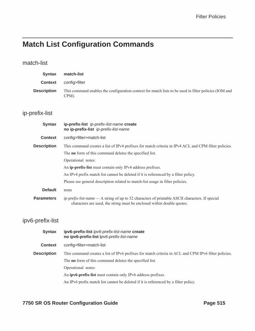
Filter Policies
Match List Configuration Commands
match-list
Syntax match-list
Context config>filter
Description This command enables the configuration context for match lists to be used in filter policies (IOM and CPM).
ip-prefix-list
Syntax ip-prefix-list ip-prefix-list-name createno ip-prefix-list ip-prefix-list-name
Context config>filter>match-list
Description This command creates a list of IPv4 prefixes for match criteria in IPv4 ACL and CPM filter policies.
The no form of this command deletes the specified list.
Operational notes:
An ip-prefix-list must contain only IPv4 address prefixes.
An IPv4 prefix match list cannot be deleted if it is referenced by a filter policy.
Please see general description related to match-list usage in filter policies.
Default none
Parameters ip-prefix-list-name — A string of up to 32 characters of printable ASCII characters. If special characters are used, the string must be enclosed within double quotes.
ipv6-prefix-list
Syntax ipv6-prefix-list ipv6-prefix-list-name createno ipv6-prefix-list ipv6-prefix-list-name
Context config>filter>match-list
Description This command creates a list of IPv6 prefixes for match criteria in ACL and CPM IPv6 filter policies.
The no form of this command deletes the specified list.
Operational notes:
An ipv6-prefix-list must contain only IPv6 address prefixes.
An IPv6 prefix match list cannot be deleted if it is referenced by a filter policy.
7750 SR OS Router Configuration Guide Page 515
Match List Configuration Commands
Please see general description related to match-list usage in filter policies.
Parameters ipv6-prefix-list-name — A string of up to 32 characters of printable ASCII characters. If special characters are used, the string must be enclosed within double quotes.
apply-path
Syntax apply-pathno apply-path
Context config>filter>match-list>ip-pfx-listconfig>filter>match-list>ipv6-pfx-list
Description This command enables context to configure auto-generation of address prefixes for IPv4 or IPv6 address prefix match lists. The context the command is executed governs whether IPv4 or IPv6 prefixes will be auto-generated.
The no form of this command removes all auto-generation configuration under the apply-path context.
Default no apply path
bgp-peers
Syntax bgp-peers index group reg-exp neighbor reg-expno bgp-peers index
Context config>filter>match-list>ip-pfx-list>apply-pathconfig>filter>match-list>ipv6-pfx-list>apply-path
Description This command configures auto-generation of IPv4 or IPv6 address prefixes (as required by the context the command is executed within) based on the base router BGP instance configuration.
group:
Configures a match against base router BGP instance group configuration. Regex wildcard match (.*) can be used to match against any group.
neighbor:
Configures a match against base router BGP instance neighbor configuration. Regex wildcard match (.*) can be used to match against any neighbor.
The no form of this command removes the bgp-peers configuration for auto-generation of address prefixes for the specified index value.
Default No embedded filter policies are included in a filter policy.
Parameters index — An integer from 1 to 255 enumerating bgp-peers auto-generation configuration within this list.
Page 516 7750 SR OS Router Configuration Guide

Filter Policies
reg-exp — A regular expression defining a macth string to be used to auto generate address prefixes. Matching is performed from the least significant digit. For example a string 10.0 matches all neighbors with addresses starting with 10; like 10.0.x.x or 10.0xx.x.x.
port-list
Syntax port-list port-list-name createno port-list port-list-name
Context config>filter>match-list
Description This command creates a list of TCP/UDP port values or ranges for match criteria in IPv4 and IPv6 ACL and CPM filter policies.
The no form of this command deletes the specified list.
Operational notes:
A port-list must contain only TCP/UDP port values or ranges.
A TCP/UDP port match list cannot be deleted if it is referenced by a filter policy.
Please see general description related to match-list usage in filter policies.
Parameters port-list-name — A string of up to 32 characters of printable ASCII characters. If special characters are used, the string must be enclosed within double quotes.
Default no ports are added to a port list by default.
port
Syntax port port-number port range start end no port
Context config>filter>match-list>port-list
Description This command configures a TCP/UDP source or destination port match criterion in IPv4 and IPv6 ACL filter policies. A packet matches this criterion if the packet TCP/UDP (as configured by protocol/next-header match) source OR destination port matches either the specified port value or a port in the specified port range or port-list.
This command is mutually exclusive with src-port and dst-port commands.
The no form of this command deletes the specified port match criterion.
Default no port
Parameters port-number — A source or destination port to be used as a match criterion specified as a decimal integer.
Values 0 — 65535
range start end — an inclusive range of source or destination port values to be used as match criteria.
7750 SR OS Router Configuration Guide Page 517

Match List Configuration Commands
start of the range and end of the range are expressed as decimal integers.
Values 0 — 65535
port-list-name — A string of up to 32 characters of printable ASCII characters. If special characters are used, the string must be enclosed within double quotes.
prefix
Syntax prefix ipv6-prefix/prefix-lengthno prefix ipv6-prefix/prefix-length
Context config>filter>match-list>ipv6-pfx-list
Description This command adds an IPv6 address prefix to an existing IPv6 address prefix match list.
The no form of this command deletes the specified prefix from the list.
Operational notes:
To add set of different prefixes, execute the command with all unique prefixes. The prefixes are allowed to overlap IPv6 address space.
An IPv6 prefix addition will be blocked, if resource exhaustion is detected anywhere in the system because of Filter Policies that use this IPv6 address prefix list.
Default No prefixes are in the list by default
Parameters ipv6-prefix — A An IPv6 address prefix written as hexadecimal numbers separated by colons with host bits set to 0. One string of zeros can be omitted so 1010::700:0:217A is equivalent to 1010:0:0:0:0:700:0:217A
Values ipv6-prefix: - IPv6 address prefix x:x:x:x:x:x:x:x (eight 16-bit pieces)x:x:x:x:x:x:d.d.d.dx: [0..FFFF]Hd: [0..255]D
prefix-length — Length of the entered IP prefix.
Values 1 — 128
prefix
Syntax prefix ip-prefix/prefix-lengthno prefix ip-prefix/prefix-length
Context config>filter>match-list>ip-prefix-list
Description This command adds an IPv4 address prefix to an existing IPv4 address prefix match list.
The no form of this command deletes the specified prefix from the list.
Operational notes:
Page 518 7750 SR OS Router Configuration Guide
Filter Policies
To add set of unique prefixes, execute the command with all unique prefixes. The prefixes are allowed to overlap IPv4 address space.
An IPv4 prefix addition will be blocked, if resource exhaustion is detected anywhere in the system because of Filter Policies that use this IPv4 address prefix list.
Default none
Parameters ip-prefix — A valid IPv4 address prefix in dotted decimal notation.
Values 0.0.0.0 to 255.255.255.255 (host bit must be 0)
prefix-length — Length of the entered IP prefix.
Values 0 — 32
7750 SR OS Router Configuration Guide Page 519

MAC Filter Entry Commands
MAC Filter Entry Commands
action
Syntax action dropaction forward [sap sap-id |sdp sdp-id]no action
Context config>filter>mac-filter>entry
Description This command configures the action for a MAC filter entry. Multiple action statements entered will overwrite previous actions parameters when defined. To remove a parameter, use the no form of the action command with the specified parameter.
The no form of the command removes the specified action statement. The filter entry is considered incomplete and hence rendered inactive without the action keyword.
Default none
Parameters drop — Specifies packets matching the entry criteria will be dropped.
forward — Specifies packets matching the entry criteria will be forwarded. Only Ethernet SAPs are supported (including q-in-q, BCP, bridged Ethernet in Frame Relay or ATM).
If neither drop nor forward is specified, the filter action is no-op and the filter entry is inactive.
sap sap-id — Specifies the SAP ID. Refer to Common CLI Command Descriptions on page 665 for SAP CLI command syntax and parameter descriptions.
match
Syntax match [frame-type 802dot3 | 802dot2-llc | 802dot2-snap | ethernet_II]no match
Context config>filter>mac-filter>entry
Description This command creates the context for entering/editing match criteria for the filter entry and specifies an Ethernet frame type for the entry.
A match context may consist of multiple match criteria, but multiple match statements cannot be entered per entry.
The no form of the command removes the match criteria for the entry-id.
Parameters frame-type keyword — The frame-type keyword configures an Ethernet frame type to be used for the MAC filter match criteria.
Default 802dot3ethernet_II
Values 802dot3, 802dot2-llc, 802dot2-snap, ethernet_II
802dot3 — Specifies the frame type is Ethernet IEEE 802.3.
Page 520 7750 SR OS Router Configuration Guide

Filter Policies
802dot2-llc — Specifies the frame type is Ethernet IEEE 802.2 LLC.
802dot2-snap — Specifies the frame type is Ethernet IEEE 802.2 SNAP.
ethernet_II — Specifies the frame type is Ethernet Type II.
7750 SR OS Router Configuration Guide Page 521

MAC Filter Match Criteria
MAC Filter Match Criteria
dot1p
Syntax dot1p ip-value [mask]no dot1p
Context config>filter>mac-filter>entry
Description Configures an IEEE 802.1p value or range to be used as a MAC filter match criterion.
When a frame is missing the 802.1p bits, specifying an dot1p match criterion will fail for the frame and result in a non-match for the MAC filter entry.
The no form of the command removes the criterion from the match entry.
SAP Egress
Egress dot1p value matching will only match if the customer payload contains the 802.1p bits. For example, if a packet ingresses on a null encapsulated SAP and the customer packet is IEEE 802.1Q or 802.1p tagged, the 802.1p bits will be present for a match evaluation. On the other hand, if a customer tagged frame is received on a dot1p encapsulated SAP, the tag will be stripped on ingress and there will be no 802.1p bits for a MAC filter match evaluation; in this case, any filter entry with a dot1p match criterion specified will fail.
Default no dot1p
Parameters ip-value — The IEEE 802.1p value in decimal.
Values 0 — 7
mask — This 3-bit mask can be configured using the following formats:
To select a range from 4 up to 7 specify p-value of 4 and a mask of 0b100 for value and mask.
Default 7 (decimal)
Values 1 — 7 (decimal)
Format Style Format Syntax Example
Decimal D 4
Hexadecimal 0xH 0x4
Binary 0bBBB 0b100
Page 522 7750 SR OS Router Configuration Guide
Filter Policies
dsap
Syntax dsap dsap-value [mask]no dsap
Context config>filter>mac-filter>entry>match
Description Configures an Ethernet 802.2 LLC DSAP value or range for a MAC filter match criterion.
This is a one-byte field that is part of the 802.2 LLC header of the IEEE 802.3 Ethernet Frame.
The snap-pid field, etype field, ssap and dsap fields are mutually exclusive and may not be part of the same match criteria.
Use the no form of the command to remove the dsap value as the match criterion.
Default no dsap
Parameters dsap-value — The 8-bit dsap match criteria value in hexadecimal.
Values 0x00 — 0xFF (hex)
mask — This is optional and may be used when specifying a range of dsap values to use as the match criteria.
This 8 bit mask can be configured using the following formats:
Default FF (hex) (exact match)
0x00 — 0xFF
dst-mac
Syntax dst-mac ieee-address [mask]no dst-mac
Context config>filter>mac-filter>entry
Description Configures a destination MAC address or range to be used as a MAC filter match criterion.
The no form of the command removes the destination mac address as the match criterion.
Default no dst-mac
Parameters ieee-address — The MAC address to be used as a match criterion.
Values HH:HH:HH:HH:HH:HH or HH-HH-HH-HH-HH-HH where H is a hexadecimal digit
Format Style Format Syntax Example
Decimal DDD 240
Hexadecimal 0xHH 0xF0
Binary 0bBBBBBBBB 0b11110000
7750 SR OS Router Configuration Guide Page 523

MAC Filter Match Criteria
mask — A 48-bit mask to match a range of MAC address values.
This 48-bit mask can be configured using the following formats:
To configure so that all packets with a source MAC OUI value of 00-03-FA are subject to a match condition then the entry should be specified as: 0003FA000000 0x0FFFFF000000
Default 0xFFFFFFFFFFFF (exact match)
Values 0x00000000000000 — 0xFFFFFFFFFFFF
etype
Syntax etype ethernet-typeno etype
Context config>filter>mac-filter>entry
Description Configures an Ethernet type II Ethertype value to be used as a MAC filter match criterion.
The Ethernet type field is a two-byte field used to identify the protocol carried by the Ethernet frame. For example, 0800 is used to identify the IPv4 packets.
The Ethernet type field is used by the Ethernet version-II frames. IEEE 802.3 Ethernet frames do not use the type field. For IEEE 802.3 frames, use the dsap, ssap or snap-pid fields as match criteria.
The snap-pid field, etype field, ssap and dsap fields are mutually exclusive and may not be part of the same match criteria.
The no form of the command removes the previously entered etype field as the match criteria.
Default no etype
Parameters ethernet-type — The Ethernet type II frame Ethertype value to be used as a match criterion expressed in hexadecimal.
Values 0x0600 — 0xFFFF
isid
Syntax isid value [to higher-value]no isid
Context config>filter>mac-filter>entry>match
Format Style Format Syntax Example
Decimal DDDDDDDDDDDDDD 281474959933440
Hexadecimal 0xHHHHHHHHHHHH 0xFFFFFF000000
Binary 0bBBBBBBB...B 0b11110000...B
Page 524 7750 SR OS Router Configuration Guide

Filter Policies
Description This command configures an ISID value or a range of ISID values to be matched by the mac-filter parent. The pbb-etype value for the related SAP (inherited from the ethernet port configuration) or for the related SDP binding (inherited from SDP configuration) will be used to identify the ISID tag.
The no form of this command removes the ISID match criterion.
Default no isid
value — Specifies the ISID value, 24 bits. When just one present identifies a particular ISID to be used for matching.
to higher-value — Identifies a range of ISIDs to be used as matching criteria.
inner-tag
Syntax inner-tag value [vid-mask]no inner-tag
Context config>filter>mac-filter>entry>match
Description This command configures the matching of the second tag that is carried transparently through the service. The inner-tag on ingress is the second tag on the frame if there are no service delimiting tags. Inner tag is the second tag before any service delimiting tags on egress but is dependent in the ingress configuration and may be set to 0 even in cases where additional tags are on the frame. This allows matching VLAN tags for explicit filtering or QoS setting when using default or null encapsulations.
The inner-tag is not applicable in ingress on dot1Q SAPs. The inner-tag may be populated on egress depending on the ingress SAP type.
On QinQ SAPs of null and default that do not strip tags inner-tag will contain the second tag (which is still the second tag carried transparently through the service.) On ingress SAPs that strip any tags, inner-tag will contain 0 even if there are more than 2 tags on the frame.
The optional vid_mask is defaulted to 4095 (exact match) but may be specified to allow pattern matching. The masking operation is ((value and vid-mask) = = (tag and vid-mask)). A value of 6 and a mask of 7 would match all VIDs with the lower 3 bits set to 6.
Note for QoS the VID type cannot be specified on the default QoS policy.
The default vid-mask is set to 4095 for exact match.
outer-tag
Syntax outer-tag value [vid-mask]no outer-tag
Context config>filter>mac-filter>entry>match
Description This command configures the matching of the first tag that is carried transparently through the service. Service delimiting tags are stripped from the frame and outer tag on ingress is the first tag after any service delimiting tags. Outer tag is the first tag before any service delimiting tags on egress. This allows matching VLAN tags for explicit filtering or QoS setting when using default or
7750 SR OS Router Configuration Guide Page 525

MAC Filter Match Criteria
null encapsulations.
On dot1Q SAPs outer-tag is the only tag that can be matched. On dot1Q SAPs with exact match (sap 2/1/1:50) the outer-tag will be populated with the next tag that is carried transparently through the service or 0 if there is no additional VLAN tags on the frame.
On QinQ SAPs that strip a single service delimiting tag, outer-tag will contain the next tag (which is still the first tag carried transparently through the service.) On SAPs with two service delimiting tags (two tags stripped) outer-tag will contain 0 even if there are more than 2 tags on the frame.
The optional vid_mask is defaulted to 4095 (exact match) but may be specified to allow pattern matching. The masking operation is ((value & vid-mask) = = (tag & vid-mask)). A value of 6 and a mask of 7 would match all VIDs with the lower 3 bits set to 6.
Note for QoS the VID type cannot be specified on the default QoS policy.
The default vid-mask is set to 4095 for exact match.
snap-oui
Syntax snap-oui [zero | non-zero]no snap-oui
Context config>filter>mac-filter>entry
Description This command configures an IEEE 802.3 LLC SNAP Ethernet Frame OUI zero or non-zero value to be used as a MAC filter match criterion.
The no form of the command removes the criterion from the match criteria.
Default no snap-oui
Parameters zero — Specifies to match packets with the three-byte OUI field in the SNAP-ID set to zero.
non-zero — Specifies to match packets with the three-byte OUI field in the SNAP-ID not set to zero.
snap-pid
Syntax snap-pid pid-valueno snap-pid
Context config>filter>mac-filter>entry
Description Configures an IEEE 802.3 LLC SNAP Ethernet Frame PID value to be used as a MAC filter match criterion.
This is a two-byte protocol id that is part of the IEEE 802.3 LLC SNAP Ethernet Frame that follows the three-byte OUI field.
The snap-pid field, etype field, ssap and dsap fields are mutually exclusive and may not be part of the same match criteria.
Note: The snap-pid match criterion is independent of the OUI field within the SNAP header. Two packets with different three-byte OUI fields but the same PID field will both match the same filter
Page 526 7750 SR OS Router Configuration Guide

Filter Policies
entry based on a snap-pid match criteria.
The no form of the command removes the snap-pid value as the match criteria.
Default no snap-pid
Parameters pid-value — The two-byte snap-pid value to be used as a match criterion in hexadecimal.
Values 0x0000 — 0xFFFF
src-mac
Syntax src-mac ieee-address [ieee-address-mask]no src-mac
Context config>filter>mac-filter>entry
Description Configures a source MAC address or range to be used as a MAC filter match criterion.
The no form of the command removes the source mac as the match criteria.
Default no src-mac
Parameters ieee-address — Enter the 48-bit IEEE mac address to be used as a match criterion.
Values HH:HH:HH:HH:HH:HH or HH-HH-HH-HH-HH-HH where H is a hexadecimal digit
ieee-address-mask — This 48-bit mask can be configured using:
To configure so that all packets with a source MAC OUI value of 00-03-FA are subject to a match condition then the entry should be specified as: 003FA000000 0xFFFFFF000000
Default 0xFFFFFFFFFFFF (exact match)
Values 0x00000000000000 — 0xFFFFFFFFFFFF
ssap
Syntax ssap ssap-value [ssap-mask]no ssap
Context config>filter>mac-filter>entry
Description This command configures an Ethernet 802.2 LLC SSAP value or range for a MAC filter match
Format Style Format Syntax Example
Decimal DDDDDDDDDDDDDD 281474959933440
Hexadecimal 0xHHHHHHHHHHHH 0x0FFFFF000000
Binary 0bBBBBBBB...B 0b11110000...B
7750 SR OS Router Configuration Guide Page 527

MAC Filter Match Criteria
criterion.
This is a one-byte field that is part of the 802.2 LLC header of the IEEE 802.3 Ethernet Frame.
The snap-pid field, etype field, ssap and dsap fields are mutually exclusive and may not be part of the same match criteria.
The no form of the command removes the ssap match criterion.
Default no ssap
Parameters ssap-value — The 8-bit ssap match criteria value in hex.
Values 0x00 — 0xFF
ssap-mask — This is optional and may be used when specifying a range of ssap values to use as the match criteria.
This 8 bit mask can be configured using the following formats:
Default none
Values 0x00 — 0xFF
Format Style Format Syntax Example
Decimal DDD 240
Hexadecimal 0xHH 0xF0
Binary 0bBBBBBBBB 0b11110000
Page 528 7750 SR OS Router Configuration Guide

Filter Policies
Policy and Entry Maintenance Commands
copy
Syntax copy ip-filter src-filter-id [src-entry src-entry-id] to dst-filter-id [dst-entry dst-entry-id] [overwrite]copy ipv6-filter src-filter-id [src-entry src-entry-id] to dst-filter-id [dst-entry dst-entry-id] [overwrite]copy mac-filter src-filter-id [src-entry src-entry-id] to dst-filter-id [dst-entry dst-entry-id] [overwrite]
Context config>filter
Description This command copies existing filter list entries for a specific filter ID to another filter ID. The copy command is a configuration level maintenance tool used to create new filters using existing filters. It also allows bulk modifications to an existing policy with the use of the overwrite keyword.If overwrite is not specified, an error will occur if the destination policy ID exists.
Parameters ip-filter — Indicates that the source-filter-id and the dest-filter-id are IP filter IDs.
ipv6-filter — This keyword indicates that the source-filter-id and the dest-filter-id are IPv6 filter IDs.
mac-filter — Indicates that the source-filter-id and the dest-filter-id are MAC filter IDs.
source-filter-id — The source-filter-id identifies the source filter policy from which the copy command will attempt to copy. The filter policy must exist within the context of the preceding keyword (ip-filter, ipv6-filter or mac-filter).
dest-filter-id — The dest-filter-id identifies the destination filter policy to which the copy command will attempt to copy. If the overwrite keyword does not follow, the filter policy ID cannot already exist within the system for the filter type the copy command is issued for. If the overwrite keyword is present, the destination policy ID may or may not exist.
overwrite — The overwrite keyword specifies that the destination filter ID may exist. If it does, everything in the existing destination filter ID will be completely overwritten with the contents of the source filter ID. If the destination filter ID exists, either overwrite must be specified or an error message will be returned. If overwrite is specified, the function of copying from source to destination occurs in a ‘break before make’ manner and therefore should be handled with care.
filter-name
Syntax filter-name filter-nameno filter-name
Context config>filter>ip-filterconfig>filter>ipv6-filter
Description This command specifies the name to associate with this filter.
7750 SR OS Router Configuration Guide Page 529

Policy and Entry Maintenance Commands
Parameters filter-name — Specifies the filter name up to 64 characters in length.
renum
Syntax renum old-entry-id new-entry-id
Context config>filter>ip-filterconfig>filter>ipv6-filterconfig>filter>mac-filter
Description This command renumbers existing MAC or IP filter entries to properly sequence filter entries.This may be required in some cases since the OS exits when the first match is found and executes the actions according to the accompanying action command. This requires that entries be sequenced correctly from most to least explicit.
Parameters old-entry-id — Enter the entry number of an existing entry.
Values 1 — 65535
new-entry-id — Enter the new entry-number to be assigned to the old entry.
Values 1 — 65535
Page 530 7750 SR OS Router Configuration Guide

Filter Policies
Redirect Policy Commands
destination
Syntax [no] destination ip-address
Context config>filter>redirect-policy
Description This command defines a destination in a redirect policy. More than one destination can be configured. Whether a destination will receive redirected packets depends on the effective priority value after evaluation.
Default none
Parameters ip-address — Specifies the IP address to send the redirected traffic.
ping-test
Syntax [no] ping-test
Context config>filter>destination>ping-testconfig>filter>destination>snmp-test
Description This command configures parameters to perform connectivity ping tests to validate the ability for the destination to receive redirected traffic.
Default none
drop-count
Syntax drop-count consecutive-failures [hold-down seconds]no drop-count
Context config>filter>destination>ping-testconfig>filter>destination>snmp-testconfig>filter>destination>url-test
Description This command specifies the number of consecutive requests that must fail for the destination to be declared unreachable and the time hold-down time to held destination unreachable before repeating tests.
Default drop-count 3 hold-down 0
Parameters consecutive-failures — Specifies the number of consecutive ping test failures before declaring the destination down.
Values 1 — 60
7750 SR OS Router Configuration Guide Page 531

Redirect Policy Commands
hold-down seconds — The amount of time, in seconds, that the system should be held down if any of the test has marked it unreachable.
Values 0 — 86400
interval
Syntax interval secondsno interval
Context config>filter>destination>ping-testconfig>filter>destination>snmp-testconfig>filter>destination>url-test
Description This command specifies the amount of time, in seconds, between consecutive requests sent to the far end host.
Default 1
Parameters seconds — Specifies the amount of time, in seconds, between consecutive requests sent to the far end host.
Values 1 — 60
timeout
Syntax timeout secondsno timeout
Context config>filter>destination>snmp-testconfig>filter>destination>url-test
Description Specifies the amount of time, in seconds, that is allowed for receiving a response from the far-end host. If a reply is not received within this time the far-end host is considered unresponsive.
Default 1
Parameters seconds — Specifies the amount of time, in seconds, that is allowed for receiving a response from the far end host.
Values 1 — 60
priority
Syntax priority priorityno priority
Context config>filter>destination
Page 532 7750 SR OS Router Configuration Guide

Filter Policies
Description Redirect policies can contain multiple destinations. Each destination is assigned an initial or base priority which describes its relative importance within the policy.
Default 100
Parameters priority — The priority, expressed as a decimal integer, used to weigh the destination’s relative importance within the policy.
Values 1 — 255
snmp-test
Syntax snmp-test test-name
Context config>filter>redirect-policy>destination
Description This command enables the context to configure SNMP test parameters.
Default none
Parameters test-name — specifies the name of the SNMP test. Allowed values are any string up to 32 characters long composed of printable, 7-bit ASCII characters. If the string contains special characters (#, $, spaces, etc.), the entire string must be enclosed within double quotes.
oid
Syntax oid oid-string community community-string
Context config>filter>redirect-policy>destination>snmp-test
Description This command specifies the OID of the object to be fetched from the destination.
Default none
Parameters oid-string — Specifies the object identifier (OID) in the OID field.
community community-string — The SNMP v2 community string or the SNMP v3 context name used to conduct this SNMP test.
return-value
Syntax return-value return-value type return-type [disable | lower-priority priority | raise-priority priority]
Context config>filter>redirect-policy>destination>snmp-test
Description This command specifies the criterion to adjust the priority based on the test result. Multiple criteria can be specified with the condition that they are not conflicting or overlap. If the returned value is within the specified range, the priority can be disabled, lowered or raised.
7750 SR OS Router Configuration Guide Page 533
Redirect Policy Commands
Default none
Parameters return-value — Specifies the SNMP value against which the test result is matched.
Values A maximum of 256 characters.
return-type — Specifies the SNMP object type against which the test result is matched.
Values integer, unsigned, string, ip-address, counter, time-ticks, opaque
disable — The keyword that specifies that the destination may not be used for the amount of time specified in the hold-time command when the test result matches the criterion.
lower-priority priority — Specifies the amount to lower the priority of the destination.
Values 1 — 255
raise-priority priority — Specifies the amount to raise the priority of the destination.
Values 1 — 255
url-test
Syntax url-test test-name
Context config>filter>redirect-policy>destination
Description The context to enable URL test parameters. IP filters can be used to selectively cache some web sites.
Default none
Parameters test-name — The name of the URL test. Allowed values are any string up to 32 characters long composed of printable, 7-bit ASCII characters. If the string contains special characters (#, $, spaces, etc.), the entire string must be enclosed within double quotes.
return-code
Syntax return-code return-code-1 [return-code-2] [disable | lower-priority priority | raise-priority priority]no return-code return-code-1 [return-code-2]
Context config>filter>redirect-policy>destination>url-test
Description Return codes are returned when the URL test is performed. Values for the specified range are the return codes which can be given back to the system as a result of the test been performed.
For example, error code 401 for HTTP is “page not found.” If, while performing this test, the URL is not reachable, you can lower the priority by 10 points so that other means of reaching this destination are prioritized higher than the older one.
Default none
Page 534 7750 SR OS Router Configuration Guide

Filter Policies
Parameters return-code-1, return-code-2 — Specifies a range of return codes. When the URL test return-code falls within the specified range, the corresponding action is performed.
Values return-code-1: 1 — 4294967294return-code-2: 2 — 4294967295
disable — Specifies that the destination may not be used for the amount of time specified in the hold-time command when the return code falls within the specified range.
lower-priority priority — Specifies the amount to lower the priority of the destination when the return code falls within the specified range.
raise-priority priority — Specifies the amount to raise the priority of the destination when the return code falls within the specified range.
url
Syntax url url-string [http-version version-string]
Context config>filter>redirect-policy>destination>url-test
Description This command specifies the URL to be probed by the URL test.
Default none
Parameters url-string — Specify a URL up to 255 characters in length.
http-version version-string — Specifies the HTTP version, 80 characters in length.
shutdown
Syntax [no] shutdown
Context config>filter>redirect-policyconfig>filter>redirect-policy>destination
Administratively enables/disabled (AdminUp/AdminDown) an entity. Downing an entity does not change, reset or remove any configuration settings or statistics. Many objects must be shutdown before they may be deleted.
The shutdown command administratively downs an entity. Administratively downing an entity changes the operational state of the entity to down.
Unlike other commands and parameters where the default state will not be indicated in the configuration file, shutdown and no shutdown are always indicated in system generated configuration files.
The no form of the command puts an entity into the administratively enabled state.
Default no shutdown
7750 SR OS Router Configuration Guide Page 535

Redirect Policy Commands
Page 536 7750 SR OS Router Configuration Guide

Filter Policies
Show Commands
dhcp
Syntax dhcp [filter-id]
Context show>filter
Description This command displays DHCP filter information.*B:TechPubs>config# show filter dhcp===============================================================================DHCP Filters===============================================================================Filter-Id Applied Description-------------------------------------------------------------------------------10 No test-dhcp-filter-------------------------------------------------------------------------------Num filter entries: 1===============================================================================*B:TechPubs>config#
*B:TechPubs>config# show filter dhcp 10===============================================================================DHCP Filter===============================================================================Filter-Id : 10 Applied : NoEntries : 0Description : test-dhcp-filter-------------------------------------------------------------------------------Filter Match Criteria-------------------------------------------------------------------------------No Match Criteria Found===============================================================================*B:TechPubs>config#
download-failed
Syntax download-failed
Context show>filter
Description This command shows all filter entries for which the download has failed.
7750 SR OS Router Configuration Guide Page 537

Show Commands
Output download-failed Output — The following table describes the filter download-failed output.
Sample Output
A:ALA-48# show filter download-failed============================================Filter entries for which download failed============================================Filter-type Filter-Id Filter-Entry--------------------------------------------ip 1 10============================================A:ALA-48#
ip
Syntax ipip embedded [inactive]ip ip-filter-id embedded [inactive]ip ip-filter-id [detail]ip ip-filter-id associationsip ip-filter-id type entry-typeip ip-filter-id counters [type entry-type]ip ip-filter-id entry entry-id countersip ip-filter-id entry entry-id [detail]
Context show>filter
Description This command shows IP filter information.
Parameters ip-filter-id — Displays detailed information for the specified filter ID and its filter entries.
Values 1 — 65535
entry entry-id — Displays information on the specified filter entry ID for the specified filter ID only.
Values 1 — 65535
associations — Appends information as to where the filter policy ID is applied to the detailed filter policy ID output.
counters — Displays counter information for the specified filter ID. Note that egress counters count the packets without Layer 2 encapsulation. Ingress counters count the packets with Layer 2 encapsulation.
Label Description
Filter-type Displays the filter type.
Filter-ID Displays the ID of the filter.
Filter-Entry Displays the entry number of the filter.
Page 538 7750 SR OS Router Configuration Guide
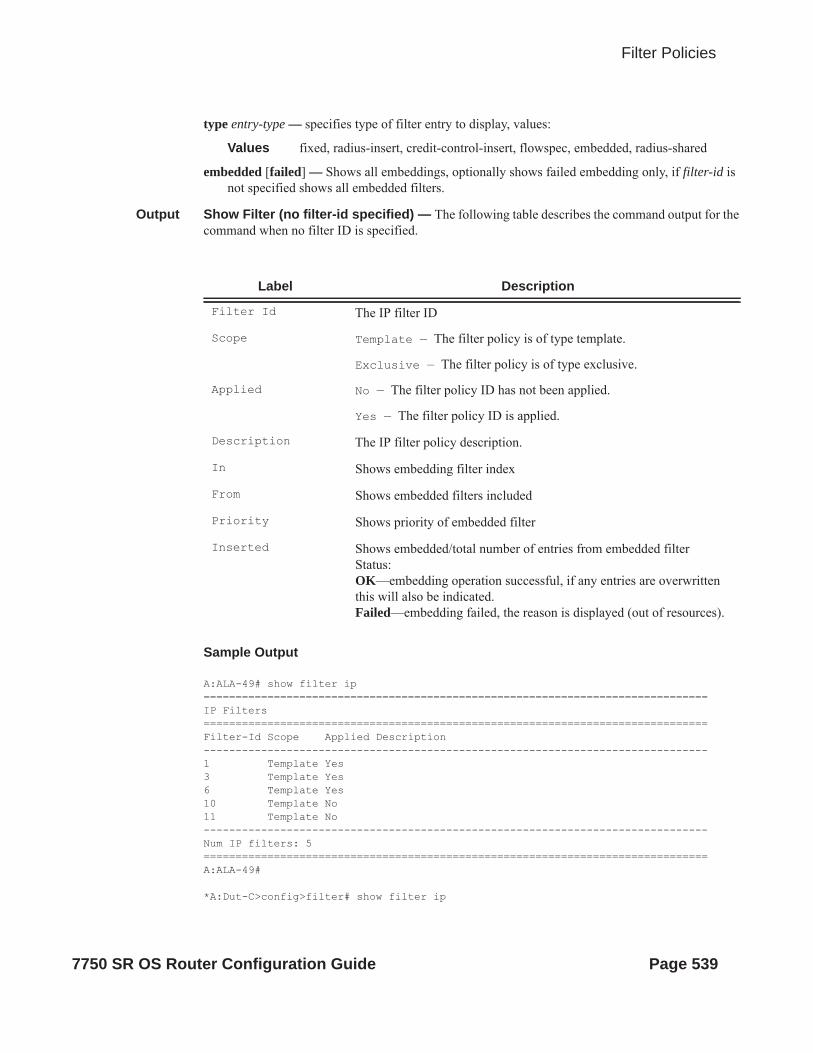
Filter Policies
type entry-type — specifies type of filter entry to display, values:
Values fixed, radius-insert, credit-control-insert, flowspec, embedded, radius-shared
embedded [failed] — Shows all embeddings, optionally shows failed embedding only, if filter-id is not specified shows all embedded filters.
Output Show Filter (no filter-id specified) — The following table describes the command output for the command when no filter ID is specified.
Sample Output
A:ALA-49# show filter ip===============================================================================IP Filters===============================================================================Filter-Id Scope Applied Description-------------------------------------------------------------------------------1 Template Yes3 Template Yes6 Template Yes10 Template No11 Template No-------------------------------------------------------------------------------Num IP filters: 5===============================================================================A:ALA-49#
*A:Dut-C>config>filter# show filter ip
Label Description
Filter Id The IP filter ID
Scope Template — The filter policy is of type template.
Exclusive — The filter policy is of type exclusive.
Applied No — The filter policy ID has not been applied.
Yes — The filter policy ID is applied.
Description The IP filter policy description.
In Shows embedding filter index
From Shows embedded filters included
Priority Shows priority of embedded filter
Inserted Shows embedded/total number of entries from embedded filterStatus:OK—embedding operation successful, if any entries are overwritten this will also be indicated.Failed—embedding failed, the reason is displayed (out of resources).
7750 SR OS Router Configuration Guide Page 539

Show Commands
===============================================================================IP Filters Total: 2===============================================================================Filter-Id Scope Applied Description-------------------------------------------------------------------------------10001 Template Yes fSpec-1 Template Yes BGP FlowSpec filter for the Base router-------------------------------------------------------------------------------Num IP filters: 2===============================================================================*A:Dut-C>config>filter# show filter ip embedded================================================IP Filter embedding================================================In From Priority Inserted Status----------------------------------------------------------------------------------10 2 50 1/1 OK
1 100 1/2 OK- 1 entry overwritten
20 2 100 0/5 Failed – out of resources================================================*A:Dut-C>config>filter#
Output Show Filter (with filter-id specified) — The following table describes the command output for the command when a filter ID is specified.
Label Description
Filter Id The IP filter policy ID.
Scope Template — The filter policy is of type template.
Exclusive — The filter policy is of type exclusive.
Entries The number of entries configured in this filter ID.
Description The IP filter policy description.
Applied No — The filter policy ID has not been applied.
Yes — The filter policy ID is applied.
Def. Action Forward — The default action for the filter ID for packets that do not match the filter entries is to forward.
Drop — The default action for the filter ID for packets that do not match the filter entries is to drop.
Filter Match Criteria
IP — Indicates the filter is an IP filter policy.
Entry The filter ID filter entry ID. If the filter entry ID indicates the entry is (Inactive), then the filter entry is incomplete as no action has been specified.
Log Id The filter log ID.
Src. IP The source IPv6 address and prefix length match criterion.
Page 540 7750 SR OS Router Configuration Guide

Filter Policies
Dest. IP The destination IPv6 address and prefix length match criterion.
Next-header The next header ID for the match criteria. Undefined indicates no next-header specified.
ICMP Type The ICMP type match criterion. Undefined indicates no ICMP type specified.
Fragment False — Configures a match on all non-fragmented IP packets.
True — Configures a match on all fragmented IP packets.
Off — Fragments are not a matching criteria. All fragments and non-fragments implicitly match.
Sampling Off — Specifies that traffic sampling is disabled.
On — Specifies that traffic matching the associated IP filter entry is sampled.
IP-Option Specifies matching packets with a specific IP option or a range of IP options in the IP header for IP filter match criteria.
TCP-syn False — Configures a match on packets with the SYN flag set to false.
True — Configured a match on packets with the SYN flag set to true.
Off — The state of the TCP SYN flag is not considered as part of the match criteria.
Match action Default — The filter does not have an explicit forward or drop match action specified. If the filter entry ID indicates the entry is Inactive, the filter entry is incomplete, no action was specified.
Drop — Drop packets matching the filter entry.
Forward — The explicit action to perform is forwarding of the packet.
Ing. Matches The number of ingress filter matches/hits for the filter entry.
Src. Port The source TCP or UDP port number or port range.
Dest. Port The destination TCP or UDP port number or port rangee.
Dscp The DiffServ Code Point (DSCP) name.
ICMP Code The ICMP code field in the ICMP header of an IP packet.
Option-present Off — Specifies not to search for packets that contain the option field or have an option field of zero.
Label Description (Continued)
7750 SR OS Router Configuration Guide Page 541
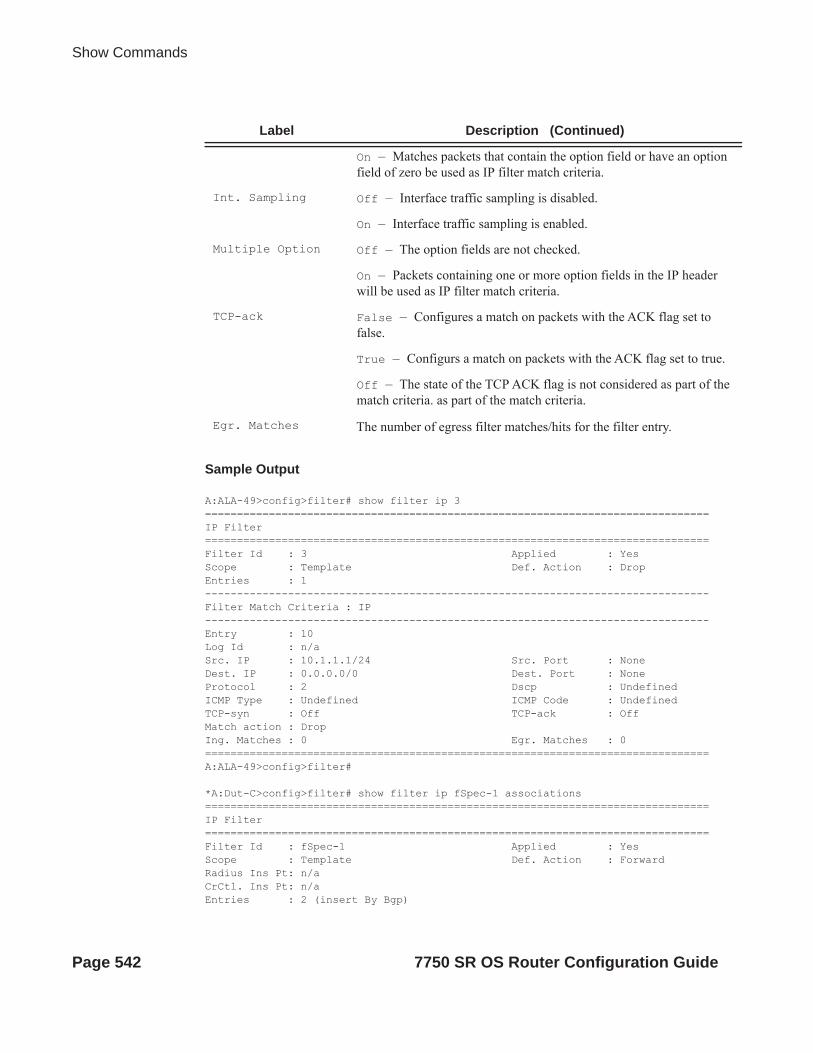
Show Commands
Sample Output
A:ALA-49>config>filter# show filter ip 3===============================================================================IP Filter===============================================================================Filter Id : 3 Applied : YesScope : Template Def. Action : DropEntries : 1-------------------------------------------------------------------------------Filter Match Criteria : IP-------------------------------------------------------------------------------Entry : 10Log Id : n/aSrc. IP : 10.1.1.1/24 Src. Port : NoneDest. IP : 0.0.0.0/0 Dest. Port : NoneProtocol : 2 Dscp : UndefinedICMP Type : Undefined ICMP Code : UndefinedTCP-syn : Off TCP-ack : OffMatch action : DropIng. Matches : 0 Egr. Matches : 0===============================================================================A:ALA-49>config>filter#
*A:Dut-C>config>filter# show filter ip fSpec-1 associations ===============================================================================IP Filter===============================================================================Filter Id : fSpec-1 Applied : YesScope : Template Def. Action : ForwardRadius Ins Pt: n/a CrCtl. Ins Pt: n/a Entries : 2 (insert By Bgp)
On — Matches packets that contain the option field or have an option field of zero be used as IP filter match criteria.
Int. Sampling Off — Interface traffic sampling is disabled.
On — Interface traffic sampling is enabled.
Multiple Option Off — The option fields are not checked.
On — Packets containing one or more option fields in the IP header will be used as IP filter match criteria.
TCP-ack False — Configures a match on packets with the ACK flag set to false.
True — Configurs a match on packets with the ACK flag set to true.
Off — The state of the TCP ACK flag is not considered as part of the match criteria. as part of the match criteria.
Egr. Matches The number of egress filter matches/hits for the filter entry.
Label Description (Continued)
Page 542 7750 SR OS Router Configuration Guide

Filter Policies
Description : BGP FlowSpec filter for the Base router-------------------------------------------------------------------------------Filter Association : IP-------------------------------------------------------------------------------Service Id : 1 Type : IES- SAP 1/1/3:1.1 (merged in ip-fltr 10001) ===============================================================================*A:Dut-C>config>filter#
*A:Dut-C>config>filter# show filter ip 10001 ===============================================================================IP Filter===============================================================================Filter Id : 10001 Applied : YesScope : Template Def. Action : DropRadius Ins Pt: n/a CrCtl. Ins Pt: n/a Entries : 1 BGP Entries : 2 Description : (Not Specified)-------------------------------------------------------------------------------Filter Match Criteria : IP-------------------------------------------------------------------------------Entry : 1 Description : (Not Specified)Log Id : n/a Src. IP : 0.0.0.0/0 Src. Port : NoneDest. IP : 0.0.0.0/0 Dest. Port : NoneProtocol : 6 Dscp : UndefinedICMP Type : Undefined ICMP Code : UndefinedFragment : Off Option-present : OffSampling : Off Int. Sampling : OnIP-Option : 0/0 Multiple Option: OffTCP-syn : Off TCP-ack : OffMatch action : Forward Next Hop : Not Specified Ing. Matches : 0 pktsEgr. Matches : 0 pkts
Entry : fSpec-1-32767 - inserted by BGP FLowSpecDescription : (Not Specified)Log Id : n/a Src. IP : 0.0.0.0/0 Src. Port : NoneDest. IP : 0.0.0.0/0 Dest. Port : NoneProtocol : 6 Dscp : UndefinedICMP Type : Undefined ICMP Code : UndefinedFragment : Off Option-present : OffSampling : Off Int. Sampling : OnIP-Option : 0/0 Multiple Option: OffTCP-syn : Off TCP-ack : OffMatch action : Drop Ing. Matches : 0 pktsEgr. Matches : 0 pkts
Entry : fSpec-1-49151 - inserted by BGP FLowSpecDescription : (Not Specified)Log Id : n/a Src. IP : 0.0.0.0/0 Src. Port : None
7750 SR OS Router Configuration Guide Page 543

Show Commands
Dest. IP : 0.0.0.0/0 Dest. Port : NoneProtocol : 17 Dscp : UndefinedICMP Type : Undefined ICMP Code : UndefinedFragment : Off Option-present : OffSampling : Off Int. Sampling : OnIP-Option : 0/0 Multiple Option: OffTCP-syn : Off TCP-ack : OffMatch action : Drop Ing. Matches : 0 pktsEgr. Matches : 0 pkts
===============================================================================*A:Dut-C>config>filter#===============================================================================Configured IP Filters Total: 4===============================================================================Filter-Id Scope Applied Description-------------------------------------------------------------------------------1 Template No 5 Exclusive No 10 Template Yes 100 Embedded N/A ===============================================================================System IP Filters Total: 1===============================================================================Filter-Id Description-------------------------------------------------------------------------------_tmnx_ofs_test of-switch 'test' embedded filter-------------------------------------------------------------------------------Num IP filters: 5==============================================================================*A:bksim4001>show>filter# ip _tmnx_ofs_test
===============================================================================IP Filter===============================================================================Filter Id : _tmnx_ofs_test Applied : NoScope : Embedded Def. Action : DropRadius Ins Pt: n/a CrCtl. Ins Pt: n/a RadSh. Ins Pt: n/a Entries : 1Description : of-switch 'test' embedded filter-------------------------------------------------------------------------------Filter Match Criteria : IP-------------------------------------------------------------------------------Entry : 1000 Description : (Not Specified)Log Id : n/a Src. IP : 0.0.0.0/0Src. Port : n/aDest. IP : 0.0.0.0/0Dest. Port : n/aProtocol : Undefined Dscp : UndefinedICMP Type : Undefined ICMP Code : UndefinedFragment : Off Src Route Opt : OffSampling : Off Int. Sampling : OnIP-Option : 0/0 Multiple Option: OffTCP-syn : Off TCP-ack : Off
Page 544 7750 SR OS Router Configuration Guide

Filter Policies
Option-pres : Off Match action : DropIng. Matches : 0 pktsEgr. Matches : 0 pkts
Output Show Filter (with time-range specified) — If a time-range is specified for a filter entry, the following is displayed.A:ALA-49# show filter ip 10===============================================================================IP Filter===============================================================================Filter Id : 10 Applied : NoScope : Template Def. Action : DropEntries : 2-------------------------------------------------------------------------------Filter Match Criteria : IP-------------------------------------------------------------------------------Entry : 1010time-range : day Cur. Status : InactiveLog Id : n/aSrc. IP : 0.0.0.0/0 Src. Port : NoneDest. IP : 10.10.100.1/24 Dest. Port : NoneProtocol : Undefined Dscp : UndefinedICMP Type : Undefined ICMP Code : UndefinedFragment : Off Option-present : OffSampling : Off Int. Sampling : OnIP-Option : 0/0 Multiple Option: OffTCP-syn : Off TCP-ack : OffMatch action : ForwardNext Hop : 138.203.228.28Ing. Matches : 0 Egr. Matches : 0
Entry : 1020time-range : night Cur. Status : ActiveLog Id : n/aSrc. IP : 0.0.0.0/0 Src. Port : NoneDest. IP : 10.10.1.1/16 Dest. Port : NoneProtocol : Undefined Dscp : UndefinedICMP Type : Undefined ICMP Code : UndefinedFragment : Off Option-present : OffSampling : Off Int. Sampling : OnIP-Option : 0/0 Multiple Option: OffTCP-syn : Off TCP-ack : OffMatch action : ForwardNext Hop : 172.22.184.101Ing. Matches : 0 Egr. Matches : 0=============================================================================== A:ALA-49#
7750 SR OS Router Configuration Guide Page 545

Show Commands
Output Show Filter Associations — The following table describes the fields that display when the associations keyword is specified.
Label Description
Filter Id The IP filter policy ID.
Scope Template — The filter policy is of type Template.
Exclusive — The filter policy is of type Exclusive.
Entries The number of entries configured in this filter ID.
Applied No — The filter policy ID has not been applied.
Yes — The filter policy ID is applied.
Def. Action Forward — The default action for the filter ID for packets that do not match the filter entries is to forward.
Drop — The default action for the filter ID for packets that do not match the filter entries is to drop.
Service Id The service ID on which the filter policy ID is applied.
SAP The Service Access Point on which the filter policy ID is applied.
(Ingress) The filter policy ID is applied as an ingress filter policy on the inter-face.
(Egress) The filter policy ID is applied as an egress filter policy on the interface.
Type The type of service of the service ID.
Entry The filter ID filter entry ID. If the filter entry ID indicates the entry is Inactive, the filter entry is incomplete as no action was specified.
Log Id The filter log ID.
Src. IP The source IP address and mask match criterion. 0.0.0.0/0 indicates no criterion specified for the filter entry.
Dest. IP The destination IP address and mask match criterion. 0.0.0.0/0 indi-cates no criterion specified for the filter entry.
Protocol The protocol ID for the match criteria. Undefined indicates no proto-col specified.
ICMP Type The ICMP type match criterion. Undefined indicates no ICMP type specified.
Fragment False — Configures a match on all non-fragmented IP packets.
True — Configures a match on all fragmented IP packets.
Page 546 7750 SR OS Router Configuration Guide

Filter Policies
Off — Fragments are not a matching criteria. All fragments and non-fragments implicitly match.
Sampling Off — Specifies that traffic sampling is disabled.
On — Specifies that traffic matching the associated IP filter entry is sampled.
IP-Option Specifies matching packets with a specific IP option or a range of IP options in the IP header for IP filter match criteria.
TCP-syn False — Configures a match on packets with the SYN flag set to false.
True — Configured a match on packets with the SYN flag set to true.
Off — The state of the TCP SYN flag is not considered as part of the match criteria.
Match action Default — The filter does not have an explicit forward or drop match action specified. If the filter entry ID indicates the entry is Inactive, the filter entry is incomplete (no action was specified).
Drop — Drop packets matching the filter entry.
Forward — The explicit action to perform is forwarding of the packet. If the action is Forward, then if configured the nexthop infor-mation should be displayed, including Nexthop: <IP address>, Indi-rect: <IP address> or Interface: <IP interface name>.
Ing. Matches The number of ingress filter matches/hits for the filter entry.
Src. Port The source TCP or UDP port number or port range.
Dest. Port The destination TCP or UDP port number or port range.
Dscp The DiffServ Code Point (DSCP) name.
ICMP Code The ICMP code field in the ICMP header of an IP packet.
Option-present Off — Specifies not to search for packets that contain the option field or have an option field of zero.
On — Matches packets that contain the option field or have an option field of zero be used as IP filter match criteria.
Int. Sampling Off — Interface traffic sampling is disabled.
On — Interface traffic sampling is enabled.
Multiple Option Off — The option fields are not checked.
On — Packets containing one or more option fields in the IP header will be used as IP filter match criteria.
Label Description (Continued)
7750 SR OS Router Configuration Guide Page 547

Show Commands
Sample Output
A:ALA-49# show filter ip 1 associations===============================================================================IP Filter===============================================================================Filter Id : 1 Applied : YesScope : Template Def. Action : DropEntries : 1-------------------------------------------------------------------------------Filter Association : IP-------------------------------------------------------------------------------Service Id : 1001 Type : VPLS - SAP 1/1/1:1001 (Ingress)Service Id : 2000 Type : IES - SAP 1/1/1:2000 (Ingress)===============================================================================Filter Match Criteria : IP-------------------------------------------------------------------------------Entry : 10Log Id : n/aSrc. IP : 10.1.1.1/24 Src. Port : NoneDest. IP : 0.0.0.0/0 Dest. Port : NoneProtocol : 2 Dscp : UndefinedICMP Type : Undefined ICMP Code : UndefinedFragment : Off Option-present : OffSampling : Off Int. Sampling : OnIP-Option : 0/0 Multiple Option: OffTCP-syn : Off TCP-ack : OffMatch action : DropIng. Matches : 0 Egr. Matches : 0===============================================================================A:ALA-49#
Output Show Filter Associations (with TOD-suite specified) — If a filter is referred to in a TOD Suite assignment, it is displayed in the show filter associations command output:
A:ALA-49# show filter ip 160 associations===============================================================================IP Filter===============================================================================Filter Id : 160 Applied : NoScope : Template Def. Action : Drop
TCP-ack False — Configures a match on packets with the ACK flag set to false.
True — configures a match on packets with the ACK flag set to true.
Off — The state of the TCP ACK flag is not considered as part of the match criteria.h criteria.
Egr. Matches The number of egress filter matches/hits for the filter entry.
Label Description (Continued)
Page 548 7750 SR OS Router Configuration Guide

Filter Policies
Entries : 0-------------------------------------------------------------------------------Filter Association : IP-------------------------------------------------------------------------------Tod-suite "english_suite" - ingress, time-range "day" (priority 5)=============================================================================== A:ALA-49#
Output Show Filter Counters — The following table describes the output fields when the counters keyword is specified..
Sample Output
*A:ALA-48# show filter ipv6 100 counters===============================================================================IPv6 Filter===============================================================================Filter Id : 100 Applied : NoScope : Template Def. Action : Forward
Label Description
IP FilterFilter Id
The IP filter policy ID.
Scope Template — The filter policy is of type Template.
Exclusive — The filter policy is of type Exclusive.
Applied No — The filter policy ID has not been applied.
Yes — The filter policy ID is applied.
Def. Action Forward — The default action for the filter ID for packets that do not match the filter entries is to forward.
Drop — The default action for the filter ID for packets that do not match the filter entries is to drop.
Filter Match Criteria
IP — Indicates the filter is an IP filter policy.
Entry The filter ID filter entry ID. If the filter entry ID indicates the entry is (Inactive), then the filter entry is incomplete as no action has been specified.
Ing. Matches The number of ingress filter matches/hits for the filter entry.
Egr. Matches The number of egress filter matches/hits for the filter entry.
Note that egress counters count the packets without Layer 2 encapsula-tion. Ingress counters count the packets with Layer 2 encapsulation.
7750 SR OS Router Configuration Guide Page 549

Show Commands
Entries : 1Description : IPv6 filter configuration-------------------------------------------------------------------------------Filter Match Criteria : IPv6-------------------------------------------------------------------------------Entry : 10Ing. Matches : 9788619 pkts (978861900 bytes) Egr. Matches : 9788619 pkts (978861900 bytes) ===============================================================================*A:ALA-48#
ipv6
Syntax ipv6ipv6 embedded [inactive]ipv6 ipv6-filter-id embedded [inactive]ipv6 ipv6-filter-id [detail]ipv6 ipv6-filter-id associationsipv6 ipv6-filter-id type entry-typeipv6 ipv6-filter-id counters [type entry-type]ipv6 ipv6-filter-id entry entry-id counters
Context show>filter
Description This command shows IPv6 filter information.
Parameters ipv6-filter-id — Displays detailed information for the specified IPv6 filter ID and filter entries.
Values 1 — 65535
entry entry-id — Displays information on the specified IPv6 filter entry ID for the specified filter ID.
Values 1 — 9999
associations — Appends information as to where the IPv6 filter policy ID is applied to the detailed filter policy ID output.
counters — Displays counter information for the specified IPv6 filter ID. Note that egress counters count the packets without Layer 2 encapsulation. Ingress counters count the packets with Layer 2 encapsulation.
embedded [failed] — Shows all embeddings, optionally shows failed embedding only, if filter-id is not specified shows all embedded filters.
type entry-type — specifies type of filter entry to display, values:
Values fixed, radius-insert, credit-control-insert, flowspec, embedded, radius-shared
Page 550 7750 SR OS Router Configuration Guide

Filter Policies
Output Show Filter (no filter-id specified) — The following table describes the command output for the command when no filter ID is specified.
Sample Output
A:ALA-48# show filter ipv6===============================================================================IP Filters===============================================================================Filter-Id Scope Applied Description-------------------------------------------------------------------------------100 Template Yes test200 Exclusive Yes-------------------------------------------------------------------------------Num IPv6 filters: 2===============================================================================A:ALA-48# show filter ipv6 embedded================================================IP Filter embedding================================================In From Priority Inserted Status----------------------------------------------------------------------------------10 2 50 1/1 OK
1 100 1/2 OK- 1 entry overwritten
20 2 100 0/5 Failed – out of resources================================================A:ALA-48#
Label Description
Filter Id The IP filter ID
Scope Template — The filter policy is of type template.
Exclusive — The filter policy is of type exclusive.
Applied No — The filter policy ID has not been applied.
Yes — The filter policy ID is applied.
Description The IP filter policy description.
In Shows embedding filter index
From Shows embedded filters included
Priority Shows priority of embedded filter
Inserted Shows embedded/total number of entries from embedded filterStatus:OK—embedding operation successful, if any entries are overwritten this will also be indicated.Failed—embedding failed, the reason is displayed (out of resources).
In Shows embedding filter index
7750 SR OS Router Configuration Guide Page 551

Show Commands
===============================================================================Configured IP Filters Total: 4===============================================================================Filter-Id Scope Applied Description-------------------------------------------------------------------------------1 Template No 5 Exclusive No 10 Template Yes 100 Embedded N/A ===============================================================================System IP Filters Total: 1===============================================================================Filter-Id Description-------------------------------------------------------------------------------_tmnx_ofs_test of-switch 'test' embedded filter-------------------------------------------------------------------------------Num IP filters: 5==============================================================================
Output Show Filter (with filter-id specified) — The following table describes the command output for the command when a filter ID is specified.
Label Description
Filter Id The IP filter policy ID.
Scope Template — The filter policy is of type template.
Exclusive — The filter policy is of type exclusive.
Entries The number of entries configured in this filter ID.
Description The IP filter policy description.
Applied No — The filter policy ID has not been applied.
Yes — The filter policy ID is applied.
Def. Action Forward — The default action for the filter ID for packets that do not match the filter entries is to forward.
Drop — The default action for the filter ID for packets that do not match the filter entries is to drop.
Filter Match Criteria
IP — Indicates the filter is an IP filter policy.
Entry The filter ID filter entry ID. If the filter entry ID indicates the entry is (Inactive), then the filter entry is incomplete as no action has been specified.
Log Id The filter log ID.
Src. IP The source IP address and mask match criterion. 0.0.0.0/0 indicates no criterion specified for the filter entry.
Page 552 7750 SR OS Router Configuration Guide

Filter Policies
Dest. IP The destination IP address and mask match criterion. 0.0.0.0/0 indi-cates no criterion specified for the filter entry.
Protocol The protocol ID for the match criteria. Undefined indicates no proto-col specified.
ICMP Type The ICMP type match criterion. Undefined indicates no ICMP type specified.
Fragment False — Configures a match on all non-fragmented IP packets.
True — Configures a match on all fragmented IP packets.
Off — Fragments are not a matching criteria. All fragments and non-fragments implicitly match.
Sampling Off — Specifies that traffic sampling is disabled.
On — Specifies that traffic matching the associated IP filter entry is sampled.
IP-Option Specifies matching packets with a specific IP option or a range of IP options in the IP header for IP filter match criteria.
TCP-syn False — Configures a match on packets with the SYN flag set to false.
True — Configured a match on packets with the SYN flag set to true.
Off — The state of the TCP SYN flag is not considered as part of the match criteria.
Match action Default — The filter does not have an explicit forward or drop match action specified. If the filter entry ID indicates the entry is (Inactive), then the filter entry is incomplete as no action has been specified.
Drop — Drop packets matching the filter entry.
Forward — The explicit action to perform is forwarding of the packet. If the action is Forward, then if configured the nexthop infor-mation should be displayed, including Nexthop: <IP address>, Indi-rect: <IP address> or Interface: <IP interface name>.
Ing. Matches The number of ingress filter matches/hits for the filter entry.
Src. Port The source TCP or UDP port number or port range.
Dest. Port The destination TCP or UDP port number or port range.
Dscp The DiffServ Code Point (DSCP) name.
ICMP Code The ICMP code field in the ICMP header of an IP packet.
Label Description (Continued)
7750 SR OS Router Configuration Guide Page 553
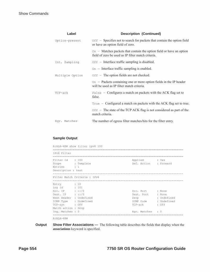
Show Commands
Sample Output
A:ALA-48# show filter ipv6 100===============================================================================IPv6 Filter===============================================================================Filter Id : 100 Applied : YesScope : Template Def. Action : ForwardEntries : 1Description : test-------------------------------------------------------------------------------Filter Match Criteria : IPv6-------------------------------------------------------------------------------Entry : 10Log Id : 101Src. IP : ::/0 Src. Port : NoneDest. IP : ::/0 Dest. Port : NoneNext Header : Undefined Dscp : UndefinedICMP Type : Undefined ICMP Code : UndefinedTCP-syn : Off TCP-ack : OffMatch action : DropIng. Matches : 0 Egr. Matches : 0===============================================================================A:ALA-48#
Output Show Filter Associations — The following table describes the fields that display when the associations keyword is specified.
Option-present Off — Specifies not to search for packets that contain the option field or have an option field of zero.
On — Matches packets that contain the option field or have an option field of zero be used as IP filter match criteria.
Int. Sampling Off — Interface traffic sampling is disabled.
On — Interface traffic sampling is enabled.
Multiple Option Off — The option fields are not checked.
On — Packets containing one or more option fields in the IP header will be used as IP filter match criteria.
TCP-ack False — Configures a match on packets with the ACK flag set to false.
True — Configured a match on packets with the ACK flag set to true.
Off — The state of the TCP ACK flag is not considered as part of the match criteria.
Egr. Matches The number of egress filter matches/hits for the filter entry.
Label Description (Continued)
Page 554 7750 SR OS Router Configuration Guide

Filter Policies
Label Description
Filter Id The IPv6 filter policy ID.
Scope Template — The filter policy is of type Template.
Exclusive — The filter policy is of type Exclusive.
Entries The number of entries configured in this filter ID.
Applied No — The filter policy ID has not been applied.
Yes — The filter policy ID is applied.
Def. Action Forward — The default action for the filter ID for packets that do not match the filter entries is to forward.
Drop — The default action for the filter ID for packets that do not match the filter entries is to drop.
Service Id The service ID on which the filter policy ID is applied.
SAP The Service Access Point on which the filter policy ID is applied.
(Ingress) The filter policy ID is applied as an ingress filter policy on the inter-face.
(Egress) The filter policy ID is applied as an egress filter policy on the interface.
Type The type of service of the service ID.
Entry The filter ID filter entry ID. If the filter entry ID indicates the entry is Inactive, the filter entry is incomplete, no action was specified.
Log Id The filter log ID.
Src. IP The source IP address and mask match criterion. 0.0.0.0/0 indicates no criterion specified for the filter entry.
Dest. IP The destination IP address and mask match criterion. 0.0.0.0/0 indi-cates no criterion specified for the filter entry.
Protocol The protocol ID for the match criteria. Undefined indicates no proto-col specified.
ICMP Type The ICMP type match criterion. Undefined indicates no ICMP type specified.
Fragment False — Configures a match on all non-fragmented IP packets.
True — Configures a match on all fragmented IP packets.
Off — Fragments are not a matching criteria. All fragments and non-fragments implicitly match.
Sampling Off — Specifies that traffic sampling is disabled.
7750 SR OS Router Configuration Guide Page 555
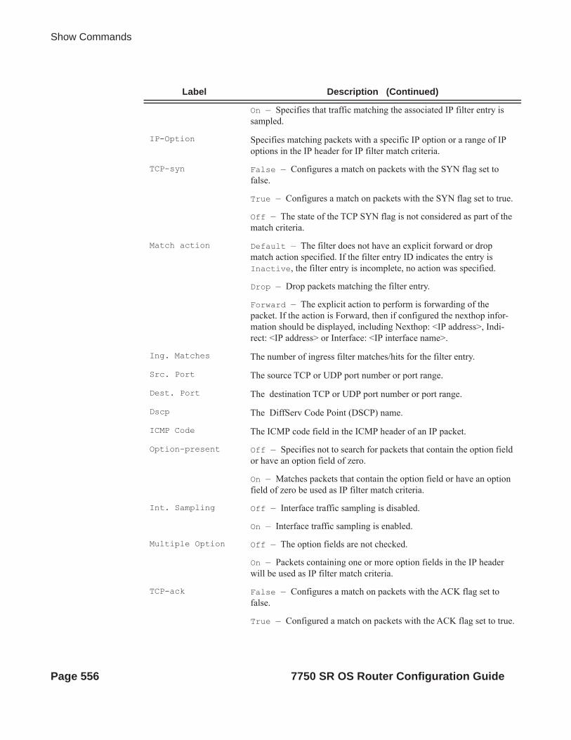
Show Commands
On — Specifies that traffic matching the associated IP filter entry is sampled.
IP-Option Specifies matching packets with a specific IP option or a range of IP options in the IP header for IP filter match criteria.
TCP-syn False — Configures a match on packets with the SYN flag set to false.
True — Configures a match on packets with the SYN flag set to true.
Off — The state of the TCP SYN flag is not considered as part of the match criteria.
Match action Default — The filter does not have an explicit forward or drop match action specified. If the filter entry ID indicates the entry is Inactive, the filter entry is incomplete, no action was specified.
Drop — Drop packets matching the filter entry.
Forward — The explicit action to perform is forwarding of the packet. If the action is Forward, then if configured the nexthop infor-mation should be displayed, including Nexthop: <IP address>, Indi-rect: <IP address> or Interface: <IP interface name>.
Ing. Matches The number of ingress filter matches/hits for the filter entry.
Src. Port The source TCP or UDP port number or port range.
Dest. Port The destination TCP or UDP port number or port range.
Dscp The DiffServ Code Point (DSCP) name.
ICMP Code The ICMP code field in the ICMP header of an IP packet.
Option-present Off — Specifies not to search for packets that contain the option field or have an option field of zero.
On — Matches packets that contain the option field or have an option field of zero be used as IP filter match criteria.
Int. Sampling Off — Interface traffic sampling is disabled.
On — Interface traffic sampling is enabled.
Multiple Option Off — The option fields are not checked.
On — Packets containing one or more option fields in the IP header will be used as IP filter match criteria.
TCP-ack False — Configures a match on packets with the ACK flag set to false.
True — Configured a match on packets with the ACK flag set to true.
Label Description (Continued)
Page 556 7750 SR OS Router Configuration Guide

Filter Policies
Sample Output
A:ALA-48# show filter ipv6 1 associations===============================================================================IPv6 Filter===============================================================================Filter Id : 1 Applied : YesScope : Template Def. Action : DropEntries : 1-------------------------------------------------------------------------------Filter Association : IPv6-------------------------------------------------------------------------------Service Id : 2000 Type : IES - SAP 1/1/1:2000 (Ingress)===============================================================================Filter Match Criteria : IPv6-------------------------------------------------------------------------------Entry : 10Log Id : 101Src. IP : ::/0 Src. Port : NoneDest. IP : ::/0 Dest. Port : NoneNext Header : Undefined Dscp : UndefinedICMP Type : Undefined ICMP Code : UndefinedTCP-syn : Off TCP-ack : OffMatch action : DropIng. Matches : 0 Egr. Matches : 0===============================================================================A:ALA-48#
Output Show Filter Counters — The following table describes the output fields when the counters keyword is specified..
Off — The state of the TCP ACK flag is not considered as part of the match criteria.
Egr. Matches The number of egress filter matches/hits for the filter entry.
Label Description (Continued)
Label Description
IP FilterFilter Id
The IP filter policy ID.
Scope Template — The filter policy is of type template.
Exclusive — The filter policy is of type exclusive.
Applied No — The filter policy ID has not been applied.
Yes — The filter policy ID is applied.
7750 SR OS Router Configuration Guide Page 557

Show Commands
Sample Output
A:ALA-48# show filter ipv6 8 counters===============================================================================IPv6 Filter===============================================================================Filter Id : 8 Applied : YesScope : Template Def. Action : ForwardEntries : 4Description : Description for Ipv6 Filter Policy id # 8-------------------------------------------------------------------------------Filter Match Criteria : IPv6-------------------------------------------------------------------------------Entry : 5Ing. Matches : 0 pktsEgr. Matches : 0 pkts Entry : 6Ing. Matches : 0 pktsEgr. Matches : 0 pkts Entry : 8Ing. Matches : 160 pkts (14400 bytes)Egr. Matches : 80 pkts (6880 bytes) Entry : 10Ing. Matches : 80 pkts (7200 bytes)Egr. Matches : 80 pkts (6880 bytes) ====================================================================================A:ALA-48#
Def. Action Forward — The default action for the filter ID for packets that do not match the filter entries is to forward.
Drop — The default action for the filter ID for packets that do not match the filter entries is to drop.
Filter Match Criteria
IP — Indicates the filter is an IP filter policy.
Entry The filter ID filter entry ID. If the filter entry ID indicates the entry is (Inactive), then the filter entry is incomplete as no action has been specified.
Ing. Matches The number of ingress filter matches/hits for the filter entry.
Egr. Matches The number of egress filter matches/hits for the filter entry.
Note that egress counters count the packets without Layer 2 encapsulation. Ingress counters count the packets with Layer 2 encapsulation.
Label Description (Continued)
Page 558 7750 SR OS Router Configuration Guide

Filter Policies
log
Syntax log log-id [match string] [bindings]
Context show>filter
Description This command shows the contents of a memory-based or a file-based filter log.
If the optional keyword match and string parameter are given, the command displays the given filter log from the first occurence of the given string.
Parameters log-id — The filter log ID destination expressed as a decimal integer.
Values 101 — 199
match string — Specifies to start displaying the filter log entries from the first occurence of string.
bindings — Displays the number of filter logs currently instantiated.
Output Log Message Formatting — Each filter log entry contains the following information in case summary log feature is not active (as appropriate).
Label Description
yyyy/mm/dd hh:mm:ss
The date and timestamp for the log filter entry where yyyy is the year, mm is the month, dd is the day, hh is the hour, mm is the minute and ss is the second.
Filter The filter ID and the entry ID which generated the filter log entry in the form Filter_ID:Entry_ID.
Desc The description of the filter entry ID which generated the filter log entry.
Interface The IP interface on which the filter ID and entry ID was associated which generated the filter log entry.
Action The action of the filter entry on the logged packet.
Src MAC The source MAC address of the logged packet.
Dst MAC The destination MAC of the logged packet.
EtherType The Ethernet type of the logged Ethernet type II packet.
Src IP The source IP address of the logged packet. The source port will be displayed after the IP address as appropriate separated with a colon.
Dst IP The destination IP address of the logged packet. The source port will be displayed after the IP address as appropriate separated with a colon.
Flags(IP flags)
M — The more fragments IP flag is set in the logged packet.DF — The do not fragment IP flag is set in the logged packet.
TOS The TOS byte value in the logged packet.
7750 SR OS Router Configuration Guide Page 559

Show Commands
If the packet being logged does not have a source or destination MAC address (i.e., POS) then the MAC information output line is omitted from the log entry.
In case log summary is active, the filter log mini-tables contain the following information..
Protocol The IP protocol of the logged packet (TCP, UDP, ICMP or a protocol number in hex).
Flags(TCP flags)
URG — Urgent bit set.ACK — Acknowledgement bit set.RST — Reset bit set.SYN — Synchronize bit set.FIN — Finish bit set.
HEX If an IP protocol does not have a supported decode, the first 32 bytes following the IP header are printed in a hex dump.Log entries for non-IP packets include the Ethernet frame information and a hex dump of the first 40 bytes of the frame after the Ethernet header.
Total Log Instances (Allowed)
Specifies the maximum allowed instances of filter logs allowed on the system.
Total Log Instances (In Use)
Specifies the instances of filter logs presently existing on the system.
Total Log Bindings Specifies the count of the filter log bindings presently existing on the system.
Type The type of service of the service ID.
Filter ID Uniquely identifies an IP filter as configured on the system.
Entry ID The identifier which uniquely identifies an entry in a filter table.
Log Specifies an entry in the filter log table.
Instantiated Specifies if the filter log for this filter entry has or has not been instan-tiated.
Label Description
Summary Log LogID Displays the log ID.
Crit1 Summary criterion that is used as index into the mini-tables of the log.
TotCnt The total count of logs.
ArpCnt Displays the total number of ARP messages logged for this log ID.
Label Description (Continued)
Page 560 7750 SR OS Router Configuration Guide

Filter Policies
Sample Filter Log Output
2007/04/13 16:23:09 Filter: 100:100 Desc: Entry-100 Interface: to-ser1 Action: Forward Src MAC: 04-5b-01-01-00-02 Dst MAC: 04-5d-01-01-00-02 EtherType: 0800Src IP: 10.10.0.1:646 Dst IP: 10.10.0.4:49509 Flags: TOS: c0 Protocol: TCP Flags: ACK 2007/04/13 16:23:10 Filter: 100:100 Desc: Entry-100 Interface: to-ser1 Action: Forward Src MAC: 04-5b-01-01-00-02 Dst MAC: 04-5d-01-01-00-02 EtherType: 0800Src IP: 10.10.0.1:646 Dst IP: 10.10.0.3:646 Flags: TOS: c0 Protocol: UDP
2007/04/13 16:23:12 Filter: 100:100 Desc: Entry-100 Interface: to-ser1 Action: Forward Src MAC: 04-5b-01-01-00-02 Dst MAC: 01-00-5e-00-00-05 EtherType: 0800Src IP: 10.10.13.1 Dst IP: 224.0.0.5 Flags: TOS: c0 Protocol: 89 Hex: 02 01 00 30 0a 0a 00 01 00 00 00 00 ba 90 00 00 00 00 00 00 00 00 00 00 ff ff ff 00 00 03 02 01
A:ALA-A>config# show filter log bindings===============================================================================Filter Log Bindings===============================================================================Total Log Instances (Allowed) : 2046Total Log Instances (In Use) : 0Total Log Bindings : 0-------------------------------------------------------------------------------Type FilterId EntryId Log Instantiated-------------------------------------------------------------------------------No Instances found===============================================================================A:ALA-A>config#
Note: A summary log will be printed only in case TotCnt is different from 0. Only the address types with at least 1 entry in the minitable will be printed. A:ALA-A>config# show filter log 190===============================================================================Summary Log[190] Crit1: SrcAddr TotCnt: 723 ArpCnt: 83 Mac 8 06-06-06-06-06-06 Mac 8 06-06-06-06-06-05 Mac 8 06-06-06-06-06-04 Mac 8 06-06-06-06-06-03
Src...Dst...
The address type indication of the key in the mini-table.
count The number of messages logged with the specified source/destination address.
address The address for which count messages where received.
Label Description (Continued)
7750 SR OS Router Configuration Guide Page 561

Show Commands
Mac 8 06-06-06-06-06-02 Ip 16 6.6.6.1 Ip 16 6.6.6.2 Ip 16 6.6.6.3 Ip 16 6.6.6.4 Ip 8 6.6.6.5Ipv6 8 3FE:1616:1616:1616:1616:1616::Ipv6 8 3FE:1616:1616:1616:1616:1616:FFFF:FFFFIpv6 8 3FE:1616:1616:1616:1616:1616:FFFF:FFFEIpv6 8 3FE:1616:1616:1616:1616:1616:FFFF:FFFDIpv6 8 3FE:1616:1616:1616:1616:1616:FFFF:FFFC ===============================================================================A:ALA-A
mac
Syntax mac [mac-filter-id [associations | counters] [entry entry-id]]
Context show>filter
Description This command displays MAC filter information.
Parameters mac-filter-id — Displays detailed information for the specified filter ID and its filter entries.
Values 1— 65535
associations — Appends information as to where the filter policy ID is applied to the detailed filter policy ID output.
counters — Displays counter information for the specified filter ID.
entry entry-id — Displays information on the specified filter entry ID for the specified filter ID only.
Values 1 — 65535
Output No Parameters Specified — When no parameters are specified, a brief listing of IP filters is produced. The following table describes the command output for the command.
Page 562 7750 SR OS Router Configuration Guide

Filter Policies
Filter ID Specified — When the filter ID is specified, detailed filter information for the filter ID
and its entries is produced. The following table describes the command output for the command.
Label Description
Filter Id The IP filter ID
Scope Template — The filter policy is of type Template.
Exclusiv — The filter policy is of type Exclusive.
Applied No — The filter policy ID has not been applied.
Yes — The filter policy ID is applied.
Description The MAC filter policy description.
Label Description
MAC FilterFilter Id
The MAC filter policy ID.
Scope Template — The filter policy is of type Template.
Exclusiv — The filter policy is of type Exclusive.
Description The IP filter policy description.
Applied No — The filter policy ID has not been applied.
Yes — The filter policy ID is applied.
Def. Action Forward — The default action for the filter ID for packets that do not match the filter entries is to forward.
Drop — The default action for the filter ID for packets that do not match the filter entries is to drop.
Filter Match Criteria
MAC — Indicates the filter is an MAC filter policy.
Entry The filter ID filter entry ID. If the filter entry ID indicates the entry is (Inactive), then the filter entry is incomplete as no action has been specified.
Description The filter entry description.
FrameType Ethernet — The entry ID match frame type is Ethernet IEEE 802.3.Ethernet II — The entry ID match frame type is Ethernet Type II.
Src MAC The source MAC address and mask match criterion. When both the MAC address and mask are all zeroes, no criterion specified for the filter entry.
Dest MAC The destination MAC address and mask match criterion. When both the MAC address and mask are all zeroes, no criterion specified for the filter entry.
7750 SR OS Router Configuration Guide Page 563
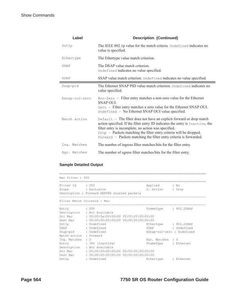
Show Commands
Sample Detailed Output
===============================================================================Mac Filter : 200===============================================================================Filter Id : 200 Applied : NoScope : Exclusive D. Action : DropDescription : Forward SERVER sourced packets-------------------------------------------------------------------------------Filter Match Criteria : Mac-------------------------------------------------------------------------------Entry : 200 FrameType : 802.2SNAPDescription : Not AvailableSrc Mac : 00:00:5a:00:00:00 ff:ff:ff:00:00:00Dest Mac : 00:00:00:00:00:00 00:00:00:00:00:00Dot1p : Undefined Ethertype : 802.2SNAPDSAP : Undefined SSAP : UndefinedSnap-pid : Undefined ESnap-oui-zero : UndefinedMatch action : ForwardIng. Matches : 0 Egr. Matches : 0Entry : 300 (Inactive) FrameType : EthernetDescription : Not AvailableSrc Mac : 00:00:00:00:00:00 00:00:00:00:00:00Dest Mac : 00:00:00:00:00:00 00:00:00:00:00:00Dot1p : Undefined Ethertype : Ethernet
Dot1p The IEEE 802.1p value for the match criteria. Undefined indicates no value is specified.
Ethertype The Ethertype value match criterion.
DSAP The DSAP value match criterion. Undefined indicates no value specified.
SSAP SSAP value match criterion. Undefined indicates no value specified.
Snap-pid The Ethernet SNAP PID value match criterion. Undefined indicates no value specified.
Esnap-oui-zero Non-Zero — Filter entry matches a non-zero value for the Ethernet SNAP OUI.Zero — Filter entry matches a zero value for the Ethernet SNAP OUI.Undefined — No Ethernet SNAP OUI value specified.
Match action Default — The filter does not have an explicit forward or drop match action specified. If the filter entry ID indicates the entry is Inactive, the filter entry is incomplete, no action was specified.Drop — Packets matching the filter entry criteria will be dropped.Forward — Packets matching the filter entry criteria is forwarded.
Ing. Matches The number of ingress filter matches/hits for the filter entry.
Egr. Matches The number of egress filter matches/hits for the filter entry.
Label Description (Continued)
Page 564 7750 SR OS Router Configuration Guide

Filter Policies
DSAP : Undefined SSAP : UndefinedSnap-pid : Undefined ESnap-oui-zero : UndefinedMatch action : DefaultIng. Matches : 0 Egr. Matches : 0===============================================================================
Filter Associations — The associations for a filter ID will be displayed if the associations keyword is specified. The assocation information is appended to the filter information. The following table describes the fields in the appended associations output.
Sample Output
A:ALA-49# show filter mac 3 associations===============================================================================Mac Filter===============================================================================Filter ID : 3 Applied : YesScope : Template Def. Action : DropEntries : 1-------------------------------------------------------------------------------Filter Association : Mac-------------------------------------------------------------------------------Service Id: 1001 Type : VPLS- SAP 1/1/1:1001 (Egress)===============================================================================A:ALA-49#
Filter Entry Counters Output — When the counters keyword is specified, the filter entry output displays the filter matches/hit information. The following table describes the command output for the command.
Label Description
Filter Associa-tion
Mac — The filter associations displayed are for a MAC filter policy ID.
Service Id The service ID on which the filter policy ID is applied.
SAP The Service Access Point on which the filter policy ID is applied.
Type The type of service of the Service ID.
(Ingress) The filter policy ID is applied as an ingress filter policy on the inter-face.
(Egress) The filter policy ID is applied as an egress filter policy on the interface.
7750 SR OS Router Configuration Guide Page 565

Show Commands
Sample Output
A:ALA-49# show filter mac 8 counters===============================================================================Mac Filter===============================================================================Filter Id : 8 Applied : YesScope : Template Def. Action : ForwardEntries : 2Description : Description for Mac Filter Policy id # 8-------------------------------------------------------------------------------Filter Match Criteria : Mac-------------------------------------------------------------------------------Entry : 8 FrameType : EthernetIng. Matches: 80 pkts (5440 bytes)
Label Description
Mac FilterFilter Id
The MAC filter policy ID.
Scope Template — The filter policy is of type Template.
Exclusive — The filter policy is of type Exclusive.
Description The MAC filter policy description.
Applied No — The filter policy ID has not been applied.
Yes — The filter policy ID is applied.
Def. Action Forward — The default action for the filter ID for packets that do not match the filter entries is to forward.
Drop — The default action for the filter ID for packets that do not match the filter entries is to drop.
Filter Match Criteria
Mac — Indicates the filter is an MAC filter policy.
Entry The filter ID filter entry ID. If the filter entry ID indicates the entry is (Inactive), then the filter entry is incomplete as no action has been specified.
FrameType Ethernet — The entry ID match frame type is Ethernet IEEE 802.3.
802.2LLC — The entry ID match frame type is Ethernet IEEE 802.2 LLC.
802.2SNAP — The entry ID match frame type is Ethernet IEEE 802.2 SNAP.
Ethernet II — The entry ID match frame type is Ethernet Type II.
Ing. Matches The number of ingress filter matches/hits for the filter entry.
Egr. Matches The number of egress filter matches/hits for the filter entry.
Page 566 7750 SR OS Router Configuration Guide

Filter Policies
Egr. Matches: 62 pkts (3968 bytes) Entry : 10 FrameType : EthernetIng. Matches: 80 pkts (5440 bytes)Egr. Matches: 80 pkts (5120 bytes)
li-mac
Syntax li-mac [li-mac-filter-id [associations | counters] [entry entry-id]]
Context show>filter
Description This command displays Lawful Intercept MAC filter information.
Parameters li-mac-filter-id — Displays detailed information for the specified Lawful Intercept filter ID and its filter entries.
Values 1— 65535
associations — Appends information as to where the Lawful Intercept filter policy ID is applied to the detailed filter policy ID output.
counters — Displays counter information for the specified Lawful Intercept filter ID.
entry entry-id — Displays information on the specified Lawful Intercept filter entry ID for the specified filter ID only.
Values 1 — 65535
Output No Parameters Specified — When no parameters are specified, a brief listing of IP filters is produced. The following table describes the command output for the command.
Filter ID Specified — When the filter ID is specified, detailed filter information for the filter ID
and its entries is produced. The following table describes the command output for the command.
Label Description
Filter Id The IP filter ID
Scope Template — The filter policy is of type Template.
Exclusiv — The filter policy is of type Exclusive.
Applied No — The filter policy ID has not been applied.
Yes — The filter policy ID is applied.
Description The MAC filter policy description.
Label Description
MAC FilterFilter Id
The MAC filter policy ID.
7750 SR OS Router Configuration Guide Page 567

Show Commands
Scope Template — The filter policy is of type Template.
Exclusiv — The filter policy is of type Exclusive.
Description The IP filter policy description.
Applied No — The filter policy ID has not been applied.
Yes — The filter policy ID is applied.
Def. Action Forward — The default action for the filter ID for packets that do not match the filter entries is to forward.
Drop — The default action for the filter ID for packets that do not match the filter entries is to drop.
Filter Match Criteria
MAC — Indicates the filter is an MAC filter policy.
Entry The filter ID filter entry ID. If the filter entry ID indicates the entry is (Inactive), then the filter entry is incomplete as no action has been specified.
Description The filter entry description.
FrameType Ethernet — The entry ID match frame type is Ethernet IEEE 802.3.Ethernet II — The entry ID match frame type is Ethernet Type II.
Src MAC The source MAC address and mask match criterion. When both the MAC address and mask are all zeroes, no criterion specified for the filter entry.
Dest MAC The destination MAC address and mask match criterion. When both the MAC address and mask are all zeroes, no criterion specified for the filter entry.
Dot1p The IEEE 802.1p value for the match criteria. Undefined indicates no value is specified.
Ethertype The Ethertype value match criterion.
DSAP The DSAP value match criterion. Undefined indicates no value specified.
SSAP SSAP value match criterion. Undefined indicates no value specified.
Snap-pid The Ethernet SNAP PID value match criterion. Undefined indicates no value specified.
Esnap-oui-zero Non-Zero — Filter entry matches a non-zero value for the Ethernet SNAP OUI.Zero — Filter entry matches a zero value for the Ethernet SNAP OUI.Undefined — No Ethernet SNAP OUI value specified.
Label Description (Continued)
Page 568 7750 SR OS Router Configuration Guide

Filter Policies
Sample Detailed Output
# show li filter li-mac "testLiMacFilter"
===============================================================================LI Mac Filter===============================================================================Filter Id : testLiMacFilter Associated : YesEntries : 4Description : test LI Mac filter setup-------------------------------------------------------------------------------Filter Match Criteria : Mac-------------------------------------------------------------------------------Entry : 10 FrameType : EthernetDescription : entry 10Src Mac : 01:02:03:04:05:06 ff:ff:ff:ff:ff:ffDest Mac :LI Source : YesIng. Matches: 0 pktsEgr. Matches: 0 pkts
Entry : 20 FrameType : EthernetDescription : entry 20Src Mac :Dest Mac : 01:02:03:04:05:06 ff:ff:ff:ff:ff:ffLI Source : YesIng. Matches: 0 pktsEgr. Matches: 0 pkts
Entry : 30 FrameType : EthernetDescription : test 30Src Mac :Dest Mac :LI Source : YesIng. Matches: 0 pktsEgr. Matches: 0 pkts
Entry : 50 FrameType : EthernetDescription : entry 50Src Mac : 00:00:01:66:00:00 00:00:0f:ff:00:00Dest Mac :LI Source : NoIng. Matches: 0 pktsEgr. Matches: 0 pkts
Match action Default — The filter does not have an explicit forward or drop match action specified. If the filter entry ID indicates the entry is Inactive, the filter entry is incomplete, no action was specified.Drop — Packets matching the filter entry criteria will be dropped.Forward — Packets matching the filter entry criteria is forwarded.
Ing. Matches The number of ingress filter matches/hits for the filter entry.
Egr. Matches The number of egress filter matches/hits for the filter entry.
Label Description (Continued)
7750 SR OS Router Configuration Guide Page 569

Show Commands
Filter Associations — The associations for a filter ID will be displayed if the associations keyword is specified. The assocation information is appended to the filter information. The following table describes the fields in the appended associations output.
Sample Output
# show li filter li-mac "testLiMacFilter" association
===============================================================================LI Mac Filter===============================================================================Filter Id : testLiMacFilter Associated : YesEntries : 4Description : test LI Mac filter setup-------------------------------------------------------------------------------Filter Association : Mac-------------------------------------------------------------------------------mac filter 1 Service Id : 60 Type : VPLS - SAP 1/1/6:7 (Ingress) - SAP 1/1/6:9 (Egress)
Filter Entry Counters Output — When the counters keyword is specified, the filter entry output displays the filter matches/hit information. The following table describes the command output for the command.
Label Description
Filter Associa-tion
Mac — The filter associations displayed are for a MAC filter policy ID.
Service Id The service ID on which the filter policy ID is applied.
SAP The Service Access Point on which the filter policy ID is applied.
Type The type of service of the Service ID.
(Ingress) The filter policy ID is applied as an ingress filter policy on the inter-face.
(Egress) The filter policy ID is applied as an egress filter policy on the interface.
Page 570 7750 SR OS Router Configuration Guide
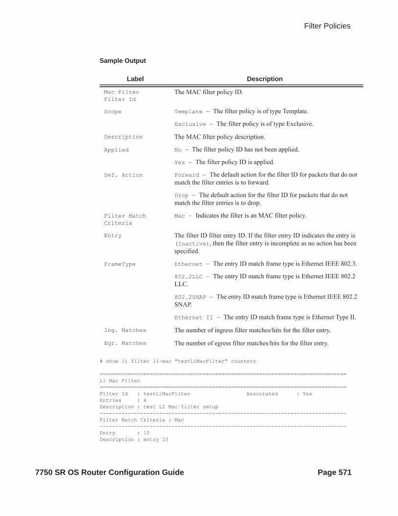
Filter Policies
Sample Output
# show li filter li-mac "testLiMacFilter" counters
===============================================================================LI Mac Filter===============================================================================Filter Id : testLiMacFilter Associated : YesEntries : 4Description : test LI Mac filter setup-------------------------------------------------------------------------------Filter Match Criteria : Mac-------------------------------------------------------------------------------Entry : 10Description : entry 10
Label Description
Mac FilterFilter Id
The MAC filter policy ID.
Scope Template — The filter policy is of type Template.
Exclusive — The filter policy is of type Exclusive.
Description The MAC filter policy description.
Applied No — The filter policy ID has not been applied.
Yes — The filter policy ID is applied.
Def. Action Forward — The default action for the filter ID for packets that do not match the filter entries is to forward.
Drop — The default action for the filter ID for packets that do not match the filter entries is to drop.
Filter Match Criteria
Mac — Indicates the filter is an MAC filter policy.
Entry The filter ID filter entry ID. If the filter entry ID indicates the entry is (Inactive), then the filter entry is incomplete as no action has been specified.
FrameType Ethernet — The entry ID match frame type is Ethernet IEEE 802.3.
802.2LLC — The entry ID match frame type is Ethernet IEEE 802.2 LLC.
802.2SNAP — The entry ID match frame type is Ethernet IEEE 802.2 SNAP.
Ethernet II — The entry ID match frame type is Ethernet Type II.
Ing. Matches The number of ingress filter matches/hits for the filter entry.
Egr. Matches The number of egress filter matches/hits for the filter entry.
7750 SR OS Router Configuration Guide Page 571

Show Commands
Ing. Matches: 0 pktsEgr. Matches: 0 pkts
Entry : 20Description : entry 20Ing. Matches: 0 pktsEgr. Matches: 0 pkts
Entry : 30Description : test 30Ing. Matches: 0 pktsEgr. Matches: 0 pkts
Entry : 50 Description : entry 50Ing. Matches: 0 pktsEgr. Matches: 0 pkts
redirect-policy
Syntax redirect-policy {redirect-policy-name [dest ip-address] [association]}
Context show>filter
Description This command shows redirect filter information.
Parameters redirect-policy-name — Displays information for the specified redirect policy.
dest ip-address — Directs the router to use a specified IP address for communication.
association — Appends association information.
Output Redirect Policy Output — The following table describes the fields in the redirect policy command output.
Label Description
Redirect Policy Specifies a specific redirect policy.
Applied Specifies whether the redirect policy is applied to a filter policy entry.
Description Displays the user-provided description for this redirect policy.
Active Destina-tion
ip address — Specifies the IP address of the active destination. none — Indicates that there is currently no active destination.
Destination Specifies the destination IP address.
Oper Priority Specifies the operational value of the priority for this destination. The highest operational priority across multiple destinations is used as the preferred destination.
Admin Priority Specifies the configured base priority for the destination.
Page 572 7750 SR OS Router Configuration Guide
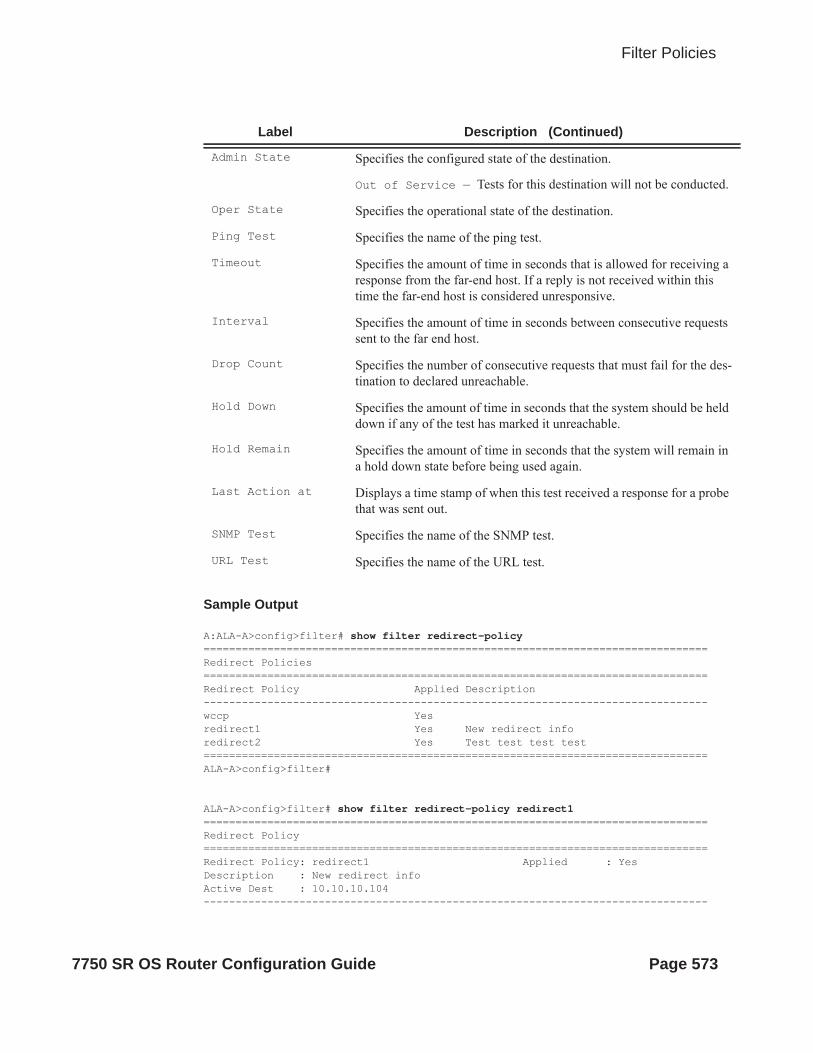
Filter Policies
Sample Output
A:ALA-A>config>filter# show filter redirect-policy===============================================================================Redirect Policies===============================================================================Redirect Policy Applied Description-------------------------------------------------------------------------------wccp Yesredirect1 Yes New redirect inforedirect2 Yes Test test test test===============================================================================ALA-A>config>filter#
ALA-A>config>filter# show filter redirect-policy redirect1===============================================================================Redirect Policy===============================================================================Redirect Policy: redirect1 Applied : YesDescription : New redirect infoActive Dest : 10.10.10.104-------------------------------------------------------------------------------
Admin State Specifies the configured state of the destination.
Out of Service — Tests for this destination will not be conducted.
Oper State Specifies the operational state of the destination.
Ping Test Specifies the name of the ping test.
Timeout Specifies the amount of time in seconds that is allowed for receiving a response from the far-end host. If a reply is not received within this time the far-end host is considered unresponsive.
Interval Specifies the amount of time in seconds between consecutive requests sent to the far end host.
Drop Count Specifies the number of consecutive requests that must fail for the des-tination to declared unreachable.
Hold Down Specifies the amount of time in seconds that the system should be held down if any of the test has marked it unreachable.
Hold Remain Specifies the amount of time in seconds that the system will remain in a hold down state before being used again.
Last Action at Displays a time stamp of when this test received a response for a probe that was sent out.
SNMP Test Specifies the name of the SNMP test.
URL Test Specifies the name of the URL test.
Label Description (Continued)
7750 SR OS Router Configuration Guide Page 573

Show Commands
Destination : 10.10.10.104-------------------------------------------------------------------------------Description : SNMP_to_104Admin Priority : 105 Oper Priority: 105Admin State : Up Oper State : Up
SNMP Test : SNMP-1Interval : 30 Timeout : 1Drop Count : 30Hold Down : 120 Hold Remain : 0Last Action at : None Taken-------------------------------------------------------------------------------Destination : 10.10.10.105-------------------------------------------------------------------------------Description : another testAdmin Priority : 95 Oper Priority: 105Admin State : Up Oper State : Down
Ping TestInterval : 1 Timeout : 30Drop Count : 5Hold Down : 0 Hold Remain : 0Last Action at : 03/19/2007 00:46:55 Action Taken : Disable-------------------------------------------------------------------------------Destination : 10.10.10.106-------------------------------------------------------------------------------Description : (Not Specified)Admin Priority : 90 Oper Priority: 90Admin State : Up Oper State : Down
URL Test : URL_to_ProxyInterval : 10 Timeout : 10Drop Count : 3Hold Down : 0 Hold Remain : 0Last Action at : 03/19/2007 05:04:15 Action Taken : DisablePriority Change: 0 Return Code : 0===============================================================================A:ALA-A>config>filter#
A:ALA-A>show filter redirect-policy redirect1 dest 10.10.10.106===============================================================================Redirect Policy===============================================================================Redirect Policy: redirect1 Applied : YesDescription : New redirect infoActive Dest : 10.10.10.104-------------------------------------------------------------------------------Destination : 10.10.10.106-------------------------------------------------------------------------------Description : (Not Specified)Admin Priority : 90 Oper Priority: 90Admin State : Up Oper State : Down
URL Test : URL_to_ProxyInterval : 10 Timeout : 10Drop Count : 3Hold Down : 0 Hold Remain : 0Last Action at : 03/19/2007 05:04:15 Action Taken : Disable
Page 574 7750 SR OS Router Configuration Guide

Filter Policies
Priority Change: 0 Return Code : 0===============================================================================ALA-A#
match-list
Syntax match-list
Context show>filter
Description This command displays information for match lists used in filter policies (IOM and CPM).
ip-prefix-list
Syntax ip-prefix-list [prefix-list-name]ip-prefix-list prefix-list-name references
Context show>filter>match-list
Description This command displays IPv4 prefixes information for match criteria in IPv4 ACL and CPM filter policies.
Parameters ip-prefix-list-name — A string of up to 32 characters of printable ASCII characters. If special characters are used, the string must be enclosed within double quotes.
ipv6-prefix-list
Syntax ipv6-prefix-list [prefix-list-name]ipv6-prefix-list prefix-list-name references
Context show>filter>match-list
Description This command displays IPv6 prefixes information for match criteria in IPv6 ACL and CPM filter policies.
Parameters ip-prefix-list-name — A string of up to 32 characters of printable ASCII characters. If special characters are used, the string must be enclosed within double quotes.
7750 SR OS Router Configuration Guide Page 575

Show Commands
port-list
Syntax port-list [port-list-name]port-list port-list-name references
Context show>filter>match-list
Description This command displays TCP/UDP port values or ranges for match criteria in IPv4 and IPv6 ACL and CPM filter policies.
Parameters port-list-name — A string of up to 32 characters of printable ASCII characters. If special characters are used, the string must be enclosed within double quotes.
Page 576 7750 SR OS Router Configuration Guide

Filter Policies
Clear Commands
ip
Syntax ip ip-filter-id [entry entry-id] [ingress | egress]
Context clear>filter
Description Clears the counters associated with the IP filter policy.
By default, all counters associated with the filter policy entries are reset. The scope of which counters are cleared can be narrowed using the command line parameters.
Default clears all counters associated with the IP filter policy entries.
Parameters ip-filter-id — The IP filter policy ID.
Values 1 — 65535
entry-id — Specifies that only the counters associated with the specified filter policy entry will be cleared.
Values 1 — 65535
ingress — Specifies to only clear the ingress counters.
egress — Specifies to only clear the egress counters.
ipv6
Syntax ipv6 ip-filter-id [entry entry-id] [ingress | egress]
Context clear>filter
Description Clears the counters associated with the IPv6 filter policy.
By default, all counters associated with the filter policy entries are reset. The scope of which counters are cleared can be narrowed using the command line parameters.
Default Clears all counters associated with the IPv6 filter policy entries.
Parameters ip-filter-id — The IP filter policy ID.
Values 1 — 65535
entry-id — Specifies that only the counters associated with the specified filter policy entry will be cleared.
Values 1 — 65535
ingress — Specifies to only clear the ingress counters.
7750 SR OS Router Configuration Guide Page 577

Show Commands
egress — Specifies to only clear the egress counters.
log
Syntax log log-id
Context clear
Description Clears the contents of a memory or file based filter log.
This command has no effect on a syslog based filter log.
Parameters log-id — The filter log ID destination expressed as a decimal integer.
Values 101 — 199
mac
Syntax mac mac-filter-id [entry entry-id] [ingress | egress]
Context clear>filter
Clears the counters associated with the MAC filter policy.
By default, all counters associated with the filter policy entries are reset. The scope of which counters are cleared can be narrowed using the command line parameters.
Default Clears all counters associated with the MAC filter policy entries
Parameters mac-filter-id — The MAC filter policy ID.
Values 1 — 65535
entry-id — Specifies that only the counters associated with the specified filter policy entry will be cleared.
Values 1 — 65535
ingress — Specifies to only clear the ingress counters.
egress — Specifies to only clear the egress counters.
Page 578 7750 SR OS Router Configuration Guide

Filter Policies
Monitor Commands
filter
Syntax filter ip ip-filter-id entry entry-id [interval seconds] [repeat repeat] [absolute | rate]
Context monitor
Description This command monitors the counters associated with the IP filter policy.
Parameters ip-filter-id — The IP filter policy ID.
Values 1 — 65535
entry-id — Specifies that only the counters associated with the specified filter policy entry will be monitored.
Values 1 — 65535
interval — Configures the interval for each display in seconds.
Default 10 seconds
Values 3 — 60
repeat repeat — Configures how many times the command is repeated.
Default 10
Values 1 — 999
absolute — When the absolute keyword is specified, the raw statistics are displayed, without pro-cessing. No calculations are performed on the delta or rate statistics.
rate — When the rate keyword is specified, the rate-per-second for each statistic is displayed instead of the delta.
filter
Syntax filter ipv6 ipv6-filter-id entry entry-id [interval seconds] [repeat repeat] [absolute | rate]
Context monitor
Description This command monitors the counters associated with the IPv6 filter policy.
Parameters ipv6-filter-id — The IP filter policy ID.
Values 1 — 65535
entry-id — Specifies that only the counters associated with the specified filter policy entry will be moniitored.
Values 1 — 65535
7750 SR OS Router Configuration Guide Page 579

Show Commands
interval — Configures the interval for each display in seconds.
Default 5 seconds
Values 3 — 60
repeat repeat — Configures how many times the command is repeated.
Default 10
Values 1 — 999
absolute — When the absolute keyword is specified, the raw statistics are displayed, without pro-cessing. No calculations are performed on the delta or rate statistics.
rate — When the rate keyword is specified, the rate-per-second for each statistic is displayed instead of the delta.
filter
Syntax filter mac mac-filter-id entry entry-id [interval seconds] [repeat repeat] [absolute | rate]
Context monitor
Description This command monitors the counters associated with the MAC filter policy.
Parameters mac-filter-id — The MAC filter policy ID.
Values 1 — 65535
entry-id — Specifies that only the counters associated with the specified filter policy entry will be cleared.
Values 1 — 65535
interval — Configures the interval for each display in seconds.
Default 5 seconds
Values 3 — 60
repeat repeat — Configures how many times the command is repeated.
Default 10
Values 1 — 999
absolute — When the absolute keyword is specified, the raw statistics are displayed, without pro-cessing. No calculations are performed on the delta or rate statistics.
rate — When the rate keyword is specified, the rate-per-second for each statistic is displayed instead of the delta.
Page 580 7750 SR OS Router Configuration Guide

Hybrid OpenFlow Switch
In This ChapterAlcatel-Lucent supports Hybrid OpenFlow Switch (H-OFS) functionality. The hybrid model allows operators to deploy Software Defined Network (SDN) traffic steering using OpenFlow (OF) atop of the existing routing/switching infrastructure.
Topics in this chapter include:
• Hybrid OpenFlow Switching on page 582• Configuration Notes on page 590
7750 SR OS Router Configuration Guide Page 581

Hybrid OpenFlow Switching
Hybrid OpenFlow SwitchingThe hybrid OpenFlow model allows operators to deploy Software Defined Network (SDN) traffic steering using OpenFlow atop of the existing routing/switching infrastructure. Some of the main benefits of the hybrid model include:
• Increased flexibility and speed for new service deployment—H-OFS implements flexible, policy-driven, standard-based Hybrid OpenFlow Switch traffic steering that allows deployment of new services and on-demand services through policy updates rather than service and infrastructure programming.
• Evolutionary capex/opex-optimized SDN deployment—The H-OFS functionality can be deployed on the existing hardware through software upgrade, realizing benefits of FlexPath programmability. The OpenFlow traffic placement is focused access only (i.e. flexible, fast, on-demand service deployment) while network infrastructure provides robustness, resiliency, scale and security.
In a basic mode of operation, a single OpenFlow Switch instance is configured on the router and controlled by a single OpenFlow controller.
The OF controller(s) and router exchange OpenFlow messages using the OpenFlow protocol (version 1.3.1) over the TCP/IPv4 control channel. Both out-of-band (default) and in-band management is supported for connectivity to the controller. An OpenFlow message is processed by the OpenFlow switch instance on the router that installs all supported H-OFS traffic steering rules in a flow table for the H-OFS instance. A single table per H-OFS instance is supported initially. The OpenFlow switch maps the flow table rules to IPv4 and IPv6 filter policies to achieve traffic steering.
The H-OFS allows operators to:
• Steer IPv4/v6 unicast traffic arriving on a Layer 3 interface in a GRT context (base router or IES interfaces) onto a specified RSVP-TE P2P LSP.
• Steer IPv4/IPv6 unicast traffic arriving on a Layer 3 interface in a GRT context (base router or IES service) onto a specified MPLS-TP LSP.
• Drop traffic.• Forward traffic using regular processing.
The router allows operators to control traffic using OF, as follows:
• Operator can select a subset of interfaces on the router to have OF rules enabled, by embedding given instance of H-OFS in filter policies used only by those interfaces.
• For the interfaces with a given H-OFS instance enabled, operator can:
Page 582 7750 SR OS Router Configuration Guide

Hybrid Open Flow Switching
Steer all traffic arriving on all interfaces with this H-OFS enabled by programming the flow table with match all entry that redirects the traffic. Steer a subset of traffic arriving on all interfaces with this H-OFS enabled by programming the flow table with match rules that select subset of traffic (as per the router supported filter match criteria).
To enable rules in a given H-OFS on an existing service router interface, an operator must:
1. Create an ingress line card policy2. Assign that line card ingress filter policy to the 7x50 service/router interface3. Embed H-OFS instance into those line card policies4. Program OF rules as required
The following interface services support OF functionality:
• L3 SAP/network interfaces for IES services• L3 Network interfaces in base router context
OpenFlow functionality is supported in addition to all existing functionality on a given interface and can be enabled with no impact on forwarding performance. Operators can move from CLI/SNMP programmed steering rules to OpenFlow operational model in service without service disruption.
7750 SR OS Router Configuration Guide Page 583

Hybrid OpenFlow Switching
Redundant Controllers and Multiple Switch Instances
The operator can configure one or more instances of an H-OFS (using SNMP/CLI interfaces) with each instance controlled by an OF-controller over a unique OF channel (using openflow protocol). One OF controller can control multiple H-OFS instances (using dedicated channels), or a dedicated OF controller per switch can be deployed. For each switch, up to two OF controllers can be deployed for redundancy. If two controllers are programmed, they operate in OFPCR_ROLE_EQUAL role. Figure 22 depicts this architecture:
Figure 22: SROS Router/Switch OF Controller/Switch Architecture Overview
OF Channels
al_0438
OF Controllers
OF SwitchInstance 1
OF SwitchInstance N
Page 584 7750 SR OS Router Configuration Guide

Hybrid Open Flow Switching
Hybrid OpenFlow Switch Steering using Filter Policies
A router H-OFS instance is embedded into line card IPv4 and IPv6 filter policies to achieve OF-controlled Policy Based Routing (PBR). When H-OFS instance is created, embedded filters (IP and IPv6) required for that instance are automatically created. The filters are created with names, as follows:
“_tmnx_ofs_<ofs_name>”, with the same name for IPv4 and IPv6 filters used.
If embedded filters cannot be allocated due to the lack of filter policy instances, the creation of an H-OFS instance will fail. When the H-OFS instance is deleted, the corresponding embedded filters are freed.
The H-OFS can be embedded only in ingress filter policies on line cards/platforms supporting embedded filters (FP2-based or newer) and for services supporting H-OFS. Embedding of an H-OFS in filter policies on unsupported services is blocked, embedding of an H-OFS in filter policies in unsupported direction or on unsupported hardware follows the general filter policy misconfiguration behavior and is not recommended. Unsupported match fields are ignored. Other match criteria may cause a packet to match an entry.
As soon as an H-OFS instance is created, the controller can program OF rules for that instance. For instance, the rules can be created prior to the H-OFS instance embedding into a filter policy or prior to a filter policy with H-OFS instance embedded being assign to an interface. This allows operator to either pre-program H-OFS steering rules, or to disable the rules without removing them from a flow table by removing the embedding. An error is returned to controller if it attempts to program rules not supported by the system. The following lists examples of the errors returned:
• unsupported instr: [OFPET_BAD_INSTRUCTION, OFPBIC_UNSUP_INST]
• unsupported action: [OFPET_BAD_ACTION, OFPBAC_BAD_TYPE]�
• unsupported output port : [OFPET_BAD_ACTION, OFPBAC_BAD_OUT_PORT]�
• unsupported match field: [OFPET_BAD_MATCH, OFPBMC_BAD_FIELD]�
• unsupported match value: [OFPET_BAD_MATCH, OFPBMC_BAD_VALUE]�
• output port invalid/deleted after flow_mod is sent to filter: OFPET_BAD_ACTION, OFPBAC_BAD_OUT_PORT]�
As the OF controller updates traffic steering rules, the Hybrid OpenFlow Switch updates the flow table rules. This automatically triggers programming of the embedded filter, which consequently causes instantiation of the rules for all services/interfaces that have a filter policy embedding this H-OFS instance. Embedding filter policy configuration/operational rules apply also to embedded filters auto-created for an H-OFS instance (see Embedded Filter Support for ACL Filter Policies section of this guide). Note that MPLS cannot be deleted if OFS rules are created that redirect to an LSP.
7750 SR OS Router Configuration Guide Page 585

Hybrid OpenFlow Switching
The auto-created embedded filters can be viewed through CLI but cannot be modified and/or deleted through filter policy CLI/SNMP. Operator can see the above embedded filters under show filter context, including the details on the filters themselves, entries programmed, interface association, statistics, etc.
The following picture depicts the H-OFS to service operator-configurable mapping example.
Figure 23: OF Flow Table Mapping to Router/Switch Service Infrastructure Example
The router allows mixing H-OFS rules from one or more H-OFS instances in a single filter policy. Co-existence of H-OFS rules in a single policy with CLI/SNMP programmed rules and/or BGP flowspec programmed rules in a single line card filter policy is also supported. Note that for mixing of the rules from multiple management entities, the controller should not program an entry in its Flow Table that would match all traffic, as this would stop evaluation of the filter policy.
al_0368
Optional Filter Rules(Any Type Including
Other Embedded Filters)
Optional Filter Rules(Any Type Including
Other Embedded Filters)
Filter-ID: ofs_ip_filter_5Scope: Embedded
Entry Range: 0 – X = 1
Filter-ID: _tmnx_ofs_testScope: Embedded
Entry Range: 0 – X = 1
Filter-ID: _tmnx_ofs_testScope: Embedded
Entry Range: 0 – X = 1
OF Switch “Test”Flow TableMax-size X
Single OF SwitchFlow Table
Two Embedded Filters:IP and IPv6 PerOF Switch Table
OF Embedded Filters IncludedInto One or More Ingress Filter
Policies to be Used bySAP/Interfaces for OF Service
Policies onSAP/InterfaceIngress Enable
OF Functionality
IPv6 Filters
IPv4 Filters
SAP orInterface
SAP orInterface
SAP orInterface
SAP orInterface
SAP orInterface
Optional Filter Rules(Any Type Including
Other Embedded Filters)
Optional Filter Rules(Any Type Including
Other Embedded Filters)
Filter-ID: _tmnx_ofs_testScope: Embedded
Entry Range: 0 – X = 1
Page 586 7750 SR OS Router Configuration Guide

Hybrid Open Flow Switching
The router supports HA for the OF Flow Table content and statistics. On an activity switch the channel goes down and is re-established by the newly active CPM. “Fail secure mode” operation takes place during channel re-establishment (OpenFlow rules continue to be applied to the arriving traffic). OF controller is expected to re-synchronize the OF table when the channel is re-established.On a router reboot, H-OFS Flow Table rules and statistics are purged. The same takes place when H-OFS instance is shutdown. The H-OFS instance cannot be deleted unless the H-OFS instance is removed first from all embedding filter policies.
7750 SR OS Router Configuration Guide Page 587
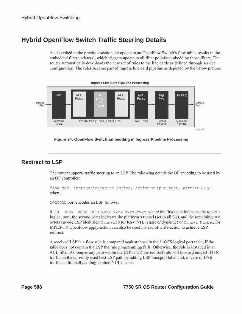
Hybrid OpenFlow Switching
Hybrid OpenFlow Switch Traffic Steering Details
As described in the previous section, an update to an OpenFlow Switch’s flow table, results in the embedded filter update(s), which triggers update to all filter policies embedding those filters. The router automatically downloads the new set of rules to the line cards as defined through service configuration. The rules became part of ingress line card pipeline as depicted by the below picture:
Figure 24: OpenFlow Switch Embedding in Ingress Pipeline Processing
Redirect to LSP
The router supports traffic steering to an LSP. The following details the OF encoding to be used by an OF controller:
flow_mod: instruction=write_action, action=output_port, port=LOGICAL, where:
LOGICAL port encodes an LSP follows:
0100 0000 0000 0000 xxxx xxxx xxxx xxxx, where the first octet indicates the router’s logical port, the second octet indicates the platform’s tunnel (set to all 0’s), and the remaining two octets encode LSP identifier: TunnelID for RSVP-TE (static or dynamic) or Tunnel Number for MPLS-TP. OpenFlow apply-action can also be used instead of write-action to achieve LSP redirect.
A received LSP in a flow rule is compared against those in the H-OFS logical port table, if the table does not contain the LSP the rule programming fails. Otherwise, the rule is installed in an ACL filter. As long as any path within the LSP is UP, the redirect rule will forward unicast IP(v6) traffic on the currently used best LSP path by adding LSP transport label and, in case of IPv6 traffic, additionally adding explicit NULL label.
al_0369
Intf ACLRules
IP Filter Policy Table (IPv4 or IPv6)
Ingress Line Card Pipe-line Processing
QoS Table Tunnel/Routing
QueuingPolicing
InterfaceTable
IngressPort
EgressPort
OFSwitchFlowTable
ACLRules
QoSPolicy
RtgFwd
QoS/TM
Page 588 7750 SR OS Router Configuration Guide

Hybrid Open Flow Switching
When an LSP in the H-OFS logical port table goes down, the OF Switch removes the LSP from its logical port table and may notify the controller of that fact if the logical port status reporting is enabled. It is up to the OF controller to decide whether to remove rules using this LSP or not. If the rules are left in the flow table, the traffic that was to be redirected to this LSP will instead be subject to a forward action for this flow rule. Note that if the controller does not remove the entries and the system re-uses the LSP identified for another LSP, the rules left in the flow table will start redirecting traffic onto this new LSP.
In some deployments, an SDN controller may need to learn from the router H-OFS logical ports status. To support that function, the OF switch supports optional status reporting using asynchronous OF protocol messages for ports status change.
Forward action
An OF controller can program forward action, when a specific flow is to be forwarded using regular router forwarding. Note that this would be a default behavior if the filter-policy embedding this OF switch instance has a default-action forward and no filter policy rule matches the flow. To implement forward action, the following OF encoding is used
flow_mod: instruction=write_action, action=output_port, port=NORMAL, where:
NORMAL is a OF reserved value. OpenFlow apply-action can also be used instead of write-action to achieve forward action.
Drop action
An OF controller can program a drop action, when packets of a specific flow are to be dropped. To implement drop action, the following OF encoding is used:
• A wildcard rule with empty action-set
7750 SR OS Router Configuration Guide Page 589

Configuration Notes
Configuration NotesThe following information describes OF implementation caveats:
• SROS Hybrid OpenFlow Switch requires S/W upgrade only and can be enabled on any SROS router/switch running IOM-2 (with restrictions) or newer line cards. For full functionality, performance and future scale IOM3-XP or newer line cards and CPM4 or newer control cards are recommended.
• Some platforms may not support all OF functionality based on underlying H/W. For example, if underlying H/W does not support IPv6, then OF IPv6 functionality will not be supported, if underlying H/W does not support redirect to LSP, redirect action will be ignored.
• Each flow in an OF flow table must have unique priority. Overlap is not supported• Timed expiry of the flow entries is not supported• The implementation is compliant by design with OpenFlow specification as applicable to
supported router functionality only. No proprietary extensions are employed to achieve the supported functionality.
Page 590 7750 SR OS Router Configuration Guide

Hybrid Open Flow Switching
OpenFlow Command Reference
Command Hierarchies• OpenFlow Commands on page 591
• Show Commands on page 591
• Tools Commands on page 591
OpenFlow Commandsconfig
— open-flow filter-id [create]— [no] of-switch ofs-name
— [no] controller ip-address:port— description description-string— no description— echo-interval seconds— no echo-interval— echo-multiple value— no echo-multiple— [no] logical-port-status [rsvp-te|mpls-tp]
— [no] flowtable of-table-id— max-size size— no max-size— no-match-action {drop | fall-through}— no no-match-action
— [no] logical-port-status {rsvp-te | mpls-tp}— [no] shutdown
Show Commandsshow
— open-flow— of-switch— of-switch ofs-name controller ip-address:port detail— of-switch ofs-name status controller [ip-address:port]— of-switch ofs-name controller— of-switch ofs-name flowtable— of-switch ofs-name status— of-switch ofs-name port
Tools Commandstools
— dump— open-flow
— of-switch [ofs-name] [flowtable of-table-id] [cookie cookie-id] [priority prior-ity]
7750 SR OS Router Configuration Guide Page 591

OpenFlow Command Reference
Page 592 7750 SR OS Router Configuration Guide

Hybrid Open Flow Switching
Configuration Commands
Generic Commands
open-flow
Syntax open-flow
Context config
Description This command enables configuration content for OpenFlow Hybrid Switch compatiblity.
The no form of the command removes the OpenFlow configuration from the context.
of-switch
Syntax [no] of-switch ofs-name
Context config>open-flow
Description This command creates an OpenFlow switch instance.
The no form of the command deletes the OpenFlow switch instance from the context.
Default no of-switch
Parameters string — Specifies the name of the OpenFlow switch instance, a string up to 32 characters.
controller
Syntax [no] controller ip-address:port
Context config>open-flow>of-switch
Description This command configures the OpenFlow controller for this OpenFlow switch. Up to two controllers can be configured per OpenFlow switch instance.
The no form of this command deletes the controller for this OpenFlow switch instance.
Default no controller
Parameters ip-address:port — Specifies the IP address and TCP port for the OpenFlow channel to the the controller.
7750 SR OS Router Configuration Guide Page 593

Generic Commands
description
Syntax description stringno description
Context config>open-flow>of-switch
Description This command allows the user to configure a description string for the specified OpenFlow controller instance.
The no form of this command deletes the description of the specified OpenFlow controller instance.
Default no controller
Parameters string — Specifies a description of the OpenFlow switch instance, a string up to 256 characters.
echo-interval
Syntax echo-interval secondsno echo-interval
Context config>open-flow>of-switch
Description This command configures the Echo Request interval for monitoring the OpenFlow control channels to the controller(s) for this OpenFlow switch instance.
The no form of this command restores default value .
Default 10
Parameters seconds — Specifies an interval, in seconds.
Values 1—3600
echo-multiple
Syntax echo-multiple valueno echo-multiple
Context config>open-flow>of-switch
Description This command configures the number of consecutive Echo Reply messages that must be lost to declare OF control channel down.
The no form of this command restores default value.
Default 3
Parameters value — Specifies the threshold value for the number of consecutive Echo Rely messages lost.
Values 3—100
Page 594 7750 SR OS Router Configuration Guide

Hybrid Open Flow Switching
logical-port-status
Syntax [no] logical-port-status [rsvp-te | mpls-tp]
Context config>open-flow>of-switch
Description This command enables status change reporting to the OpenFlow controller for the specified logical port type. To report on multiple logical port types, the command needs to be executed multiple times with different logical port specified as required.
The no form of this command disables status reporting for specified or all (no argument) logical ports.
Default no logical-port-status
Parameters rsvp-te — Enables reporting on RSVP-TE LSP logical ports.
mpls-te — Enables reporting on MPLS-TE logical ports.
shutdown
Syntax [no] shutdown
Context config>open-flow>of-switch
Description This command administratively enables or disables the OpenFlow switch instance. Disabling the switch purges all flowtable entries.
Default shutdown
flowtable
Syntax [no] flowtable of-table-id
Context config>open-flow>of-switch
Description This command configures the flow table parameters for this OpenFlow switch instance.
The no form of this command restores flow table configuration default settings.
Default no flowtable
Parameters of-table-id — Specifies an identifier of the OpenFlow table, a string up to 256 characters.
max-size
Syntax max-size sizeno max-size
Context config>open-flow>of-switch>flowtable
7750 SR OS Router Configuration Guide Page 595

Generic Commands
Description This command configures the size for the specified flow table. The OpenFlow switch instance must be shutdown to modify this parameter.
The no form of this command restores the default size.
Default no max-size
Parameters size — Specifies the maxiumum size limit for the flow table.
Values 1—1000
no-match-action
Syntax no-match-action {drop | fall-through}no no-match-action
Context config>open-flow>of-switch>flowtable
Description This command configures the action for the Flow Table when a packet does not match any entry for the controller. The OpenFlow switch instance must be shutdown to modify this parameter.
The no form of this command restores the default action.
Default no-match-action fall-through
Parameters drop — Packets that do not match entries in the flow table as programmed by the OpenFlow switch will be dropped
fall-through — Packets that do not match entries in the flow table as programmed by the OpenFlow switch will be forwarded using regular processing of the router. Note that fall-through applies if an error occurs that prevents a flow-table from being installed in a filter policy.
Page 596 7750 SR OS Router Configuration Guide

Hybrid Open Flow Switching
Show Commands
open-flow
Syntax open-flow
Context show
Description Displays OpenFlow switch hybrid information.
of-switch
Syntax of-switchof-switch ofs-name controller ip-address:port detailof-switch ofs-name status controller [ip-address:port]of-switch ofs-name controllerof-switch ofs-name flowtableof-switch ofs-name statusof-switch ofs-name port
Context show>open-flow
Description This command displays information related to H-OFS configuration and operations as per parameters specified.
Parameters none — Displays a summary for H-OFS instances configured.
ofs-name — Specifies the name of the configured H-OFS instance, up to 32 characters.
controller ip-address:port — Displays information on the controller for the specified H-OFS instance.
Values ip-address: a.b.c.dport: 1—65535
detail — Displays detailed information.
status — Displays status information for the specified H-OFS switch or its controller.
flowtable — Displays information about flowtables for the specified H-OFS instance.
port — Displays information about the logical OpenFlow ports registered with the specified H-OFS instance.
Sample Output
*A:Dut-A# show open-flow of-switch "s1" status ===============================================================================Open Flow Switch Information
7750 SR OS Router Configuration Guide Page 597

Show Commands
===============================================================================Switch Name : s1Data Path ID : 0 Admin Status : UpEcho Interval : 10 seconds Echo Multiple : 3Logical Port Type : allBuffer Size : 256 Num. of Tables : 1Description : test-sw1Capabilities Supp. : flow-stats table-stats port-stats=============================================================================== *A:Dut-A# show open-flow of-switch "s1" controller ===============================================================================Open Flow Controller Summary===============================================================================IP Address Port-------------------------------------------------------------------------------10.20.1.2 663310.20.1.3 6633-------------------------------------------------------------------------------Number of Controllers : 2-------------------------------------------------------------------------------=============================================================================== *A:Dut-A# show open-flow of-switch "s1" controller 10.20.1.2:6633 detail ===============================================================================Open Flow Controller Information===============================================================================IP Address : 10.20.1.2 Port : 6633Role : equal Generation ID : 0 -------------------------------------------------------------------------------Open Flow Channel Information-------------------------------------------------------------------------------Channel ID : 1 Version : 4Connection Type : primary Operational Status: UpOperational Flags : socketStateEstablished helloReceived helloTransmitted handshakeAsync Fltr Packet In (Master or Equal) : tableMiss applyAction (Slave) : (Not Specified)Async Fltr Port Status (Master or Equal) : portAdd portDelete portModify (Slave) : portAdd portDelete portModifyAsync Fltr Flow Rem (Master or Equal) : idleTimeOut hardTimeOut flowModDelete groupDelete (Slave) : (Not Specified)
Echo Time Expiry : 0d 00:00:10 Hold Time Expiry : 0d 00:00:30Conn. Uptime : 0d 00:00:00 Conn. Retry : 0d 00:00:00 -------------------------------------------------------------------------------Open Flow Channel Stats - Channel ID(1)-------------------------------------------------------------------------------Packet Type Transmitted Packets Received Packets Error Packets-------------------------------------------------------------------------------Hello 1 1 0Error 0 0 0
Page 598 7750 SR OS Router Configuration Guide

Hybrid Open Flow Switching
Echo Request 0 70 0Echo Reply 70 0 0Experimenter 0 0 0Feat. Request 0 1 0Feat. Reply 1 0 0Get Cfg Request 0 1 0Get Cfg Reply 1 0 0Set Config 0 1 0Packet In 0 0 0Flow Removed 0 0 0Port Status 0 0 6Packet Out 0 0 0Flow Modify 0 0 0Group Modify 0 0 0Port Modify 0 0 0Table Modify 0 0 0Multipart Req 0 0 0Multipart Reply 0 0 0Barrier Request 0 0 0Barrier Reply 0 0 0Get Q Cfg Req 0 0 0Get Q Cfg Reply 0 0 0Role Request 0 0 0Role Reply 0 0 0Get Async Req 0 0 0Get Async Reply 0 0 0Set Async 0 0 0Meter Modify 0 0 0--------------------------------------------------------------------------------------------------------------------------------------------------------------=============================================================================== *A:Dut-A# show open-flow of-switch "s1" flowtable ===============================================================================Flow Table Information===============================================================================Flow Table ID : 0 Max-Size : 1000No-Match Action : fall-through Curr Num. of Entries : 1 Max. Num. of Entries : 54=============================================================================== *A:Dut-A# show open-flow of-switch "s1" port ===============================================================================Open Flow Port Stats===============================================================================Port ID Port Name Transmitted Packets Transmitted Bytes-------------------------------------------------------------------------------1073741825 to_B 0 01073741826 to_C 0 01073741827 to_D 0 01073741828 to_E 0 01073741829 to_F 0 01073742824 1 0 0===============================================================================
7750 SR OS Router Configuration Guide Page 599

Show Commands
Debug Commands
open-flow
Syntax open-flow
Context tools>dump
Description This command enables dumping of the open-flow information.
of-switch
Syntax of-switch [ofs-name] [flowtable of-table-id] [cookie cookie-id] [priority priority]
Context tools>dump>open-flow
Description This command can be used to dump information for a given open-flow switch or its flowtable. Prioirty and cookie filters are provided no focus on part of a flow table.
Parameters ofs-name — Specifies the name of the OFS instance, up to 32 characters.
of-table-id — Specifies the identifier for the OpenFlow table.
cookie-id — Specifies the identifier for the OpenFlow cookies.
priority — Specifies the priority for the OpenFlow switch.
Sample Output
*A:Dut-C# tools dump open-flow of-switch "OFS1"===============================================================================Switch: OFS1===============================================================================Table : 0 Flow Pri : 0Cookie : 0x0000000000000000 Controller: :::0 Filter Hnd: 0xC30000010000005A Filter Pri: 90 EthType : * Src IP : *Dst IP : *IP Proto : * DSCP : *Src Port : * Dst Port : *ICMP Type : * ICMP Code : *Label : * IPv6ExtHdr: (Not Specified) Action : Fall-through Flow Flags: IPv4/6 [!E] [RO] [DEF] Up Time : 0d 20:46:31 Add TS : 1023777
Page 600 7750 SR OS Router Configuration Guide

Hybrid Open Flow Switching
Mod TS : 0 Stats TS : 8502534#Packets : 0 #Bytes : 0-------------------------------------------------------------------------------Table : 0 Flow Pri : 89Cookie : 0x0000000000000000 Controller: 20.11.2.1:6631 Filter Hnd: 0x4300000100000001 Filter Pri: 1 EthType : 0x86dd Src IP : 3FFE::101:2:0:0:0:0/128Dst IP : 3FFE::303:2:0:0:0:0/128IP Proto : * DSCP : beSrc Port : * Dst Port : *ICMP Type : * ICMP Code : *Label : 0x00000 Label Mask: *IPv6ExtHdr: Frag, Action : Drop Flow Flags: IPv6 Up Time : 0d 00:00:06 Add TS : 8502321Mod TS : 0 Stats TS : 8502534#Packets : 0 #Bytes : 0-------------------------------------------------------------------------------Number of flows: 2===============================================================================
7750 SR OS Router Configuration Guide Page 601

Show Commands
Page 602 7750 SR OS Router Configuration Guide

Cflowd
In This ChapterThis chapter provides information to configure Cflowd.
Topics in this chapter include:
• Cflowd Overview on page 604 Operation on page 605 Cflowd Filter Matching on page 609
• Cflowd Configuration Process Overview on page 610• Configuration Notes on page 611
7750 SR OS Router Configuration Guide Page 603

Cflowd OverviewCflowd is a tool used to sample IPv4, IPv6, MPLS, and Ethernet traffic data flows through a router. Cflowd enables traffic sampling and analysis by ISPs and network engineers to support capacity planning, trends analysis, and characterization of workloads in a network service provider environment.
Cflowd is also useful for traffic engineering, network planning and analysis, network monitoring, developing user profiles, data warehousing and mining, as well as security-related investigations. Collected information can be viewed several ways such as in port, AS, or network matrices, and pure flow structures. The amount of data stored depends on the cflowd configurations.
Cflowd maintains a list of data flows through a router. A flow is a uni-directional traffic stream defined by several characteristics such as source and destination IP addresses, source and destination ports, inbound interface, IP protocol and TOS bits.
When a router receives a packet for which it currently does not have a flow entry, a flow structure is initialized to maintain state information regarding that flow, such as the number of bytes exchanged, IP addresses, port numbers, AS numbers, etc. Each subsequent packet matching the same parameters of the flow contribute to the byte and packet count of the flow until the flow is terminated and exported to a collector for storage.
Cflowd is not supported on the 7750 SR-1 chassis.
Page 604 7750 SR OS Router Configuration Guide

Cflowd
Operation
Figure 25 depicts the basic operation of the cflowd feature. This sample flow is only used to describe the basic steps that are performed. It is not intended to specify implementation.
Figure 25: Basic Cflowd Steps
1. As a packet ingresses a port, a decision is made to forward or drop the packet.2. If the packet is forwarded, it is then decided if the packet should be sampled for cflowd. 3. If a new flow is found, a new entry is added to the cache. If the flow already exists in the
cache, the flow statistics are updated. 4. If a new flow is detected and the maximum number of entries are already in the flow cache, the
earliest expiry entry is removed. The earliest expiry entry/flow is the next flow that will expire due to the active or inactive timer expiration.
5. If a flow has been inactive for a period of time equal to or greater then the inactive timer (default 15 seconds), then the entry is removed from the flow cache.
6. If a flow has been active for a period of time equal to or greater than the active timer (default 30 minutes), then the entry is removed from the flow cache.
copy of header sent to cflowd
HEADERINFORMATIONPROCESSED
AND FLOW CACHEUPDATED
INGRESS PORT FORWARD/DROP ?
SAMPLE?FINISH FORWARDINGPROCESS AND SEND
TO EGRESS PORTEGRESS PORT
drop
BIT BUCKET
NEW OREXISTING
FLOW?
existing flow
newflow ADD ENTRY
FLOW CACHEEXPORT
TOCOLLECTORUPDATE
ENTRY
7750 SR OS Router Configuration Guide Page 605

When a flow is exported from the cache, the collected data is sent to an external collector which maintains an accumulation of historical data flows that network operators can use to analyze traffic patterns.
Data is exported in one of the following formats:
• Version 5 — Generates a fixed export record for each individual flow captured. • Version 8 — Aggregates multiple individual flows into a fixed aggregate record.• Version 9 — Generates a variable export record, depending on user configuration and
sampled traffic type (IPv4, IPv6, or MPLS), for each individual flow captured. • Version 10 (IPFIX) — Generates a variable export record, depending on user
configuration and sampled traffic type (IPv4, IPv6, or MPLS), for each individual flow captured.
Figure 26 depicts Version 5, Version 8, Version 9, and Version 10 flow processing.
Figure 26: V5, V8, V9, V10, and Flow Processing
1. As flows are expired from the active flow cache, the export format must be determined, either Version 5, Version 8, Version 9, and Version 10.
2. If the export format is Version 5 or Version 9 and Version 10, no further processing is per-formed and the flow data is accumulated to be sent to the external collector.
3. If the export format is Version 8, then the flow entry is added to one or more of the configured aggregation matrices.
DATA AGEDFROM ACTIVEFLOW CACHE
V5/V8/V9/V10FORMAT
V8
v5/v9/v10
FORMAT AND SEND V5 RECORDTO EXTERNAL COLLECTOR
ADD ENTRY
V8 AGGREGATE FLOW CACHE
V8 AGGREGATE FLOW CACHE
V8 AGGREGATE FLOW CACHE
AGE AGGREGATEFLOWS
FORMAT AND SEND V8 RECORDTO EXTERNAL COLLECTOR
Page 606 7750 SR OS Router Configuration Guide

Cflowd
As the entries within the aggregate matrices are aged out, they are accumulated to be sent to the external flow collector in Version 8 format.
The sample rate and cache size are configurable values. The cache size default is 64K flow entries.
A flow terminates when one of the following conditions is met:
• When the inactive timeout period expires (default: 15 seconds). A flow is considered terminated when no packets are seen for the flow for N seconds.
• When an active timeout expires (default: 30 seconds). Default active timeout is 30 minutes. A flow terminates according to the time duration regardless of whether or not there are packets coming in for the flow.
• When the user executes a clear cflowd command.• When other measures are met that apply to aggressively age flows as the cache becomes
too full (such as overflow percent).
Version 8
There are several different aggregate flow types including:
• AS matrix• Destination prefix matrix• Source prefix matrix• Prefix matrix• Protocol/port matrix.
V8 is an aggregated export format. As individual flows are aged out of the raw flow cache, the data is added to the aggregate flow cache for each configured aggregate type. Each of these aggregate flows are also aged in a manner similar to the method the active flow cache entries are aged. When an aggregate flow is aged out, it is sent to the external collector in the V8 record format.
Version 9
The Version 9 format is a more flexible format and allows for different templates or sets of cflowd data to be sent based on the type of traffic being sampled and the template set configured.
Version 9 is interoperable with RFC 3954, Cisco Systems NetFlow Services Export Version 9.
7750 SR OS Router Configuration Guide Page 607

Version 10
Version 10 is a new format and protocol that inter-operates with the specifications from the IETF as the IP Flow Information Export (IPFIX) standard. Like Version 9, the version 10 format uses templates to allow for different data elements regarding a flow that is to be exported and to handle different type of data flows such as IPv4, IPv6, and MPLS.
Version 10 is interoperable with RFC 5150 and 5102.
Page 608 7750 SR OS Router Configuration Guide

Cflowd
Cflowd Filter Matching
In the filter-matching process, normally, every packet is matched against filter (access list) criteria to determine acceptability. With cflowd, only the first packet of a flow is checked. If the first packet is forwarded, an entry is added to the cflowd cache. Subsequent packets in the same flow are then forwarded without needing to be matched against the complete set of filters. Specific performance varies depending on the number and complexity of the filters.
7750 SR OS Router Configuration Guide Page 609

Cflowd Configuration Process OverviewFigure 27 displays the process to configure Cflowd parameters.
Figure 27: Cflowd Configuration and Implementation Flow
There are three modes in which cflowd can be enabled to sample traffic on a given interface:
• Cflowd interface, where all traffic entering a given port will be subjected to sampling as the configured sampling rate
• Cflowd interface plus the definition of IP filters which specify an action of interface-disable-sample, in which traffic that matches these filter entries will not be subject to cflowd sampling.
• Cflowd ACL, where IP filters must be created with entries containing the action filter-sampled. In this mode only traffic matching these filter entries will be subject to the cflowd sampling process.
ENABLE
START
CONFIGURE COLLECTOR(S)
SPECIFY ROUTER INTERFACE FOR COLLECTION ACL OR INTERFACE
ENABLE IP FILTER ENTRY FILTER SAMPLING
APPLY FILTER TO INTERFACE
FOR CFLOWD ACL MODE:IN AN IP-FILTER ENTRY:
CONFIGURE CFLOWD PARAMETERS
FOR CFLOWD INTERFACE MODE:ENABLE INTERFACE-DISABLE-SAMPLE
IN AN IP-FILTER ENTRY:
ENABLE CFLOWD
Page 610 7750 SR OS Router Configuration Guide

Cflowd
Configuration NotesThe following cflowd components must be configured for cflowd to be operational:
• Cflowd is enabled globally.• At least one collector must be configured and enabled.• A cflowd option must be specified and enabled on a router interface.• Sampling must be enabled on either:
An IP filter which is applied to a port or service. An interface on a port or service.
7750 SR OS Router Configuration Guide Page 611

Page 612 7750 SR OS Router Configuration Guide

Cflowd
Configuring Cflowd with CLIThis section provides information to configure cflowd using the command line interface.
Topics in this section include:
• Cflowd Configuration Overview on page 614 Traffic Sampling on page 614 Collectors on page 615 Aggregation on page 615
• Basic Cflowd Configuration on page 617• Common Configuration Tasks on page 618
Enabling Cflowd on page 620 Configuring Global Cflowd Parameters on page 621 Configuring Cflowd Collectors on page 622 Dependencies on page 637 Enabling Cflowd on Interfaces and Filters on page 633 Specifying Cflowd Options on an IP Interface on page 634 Specifying Sampling Options in Filter Entries on page 636
• Cflowd Configuration Management Tasks on page 639 Modifying Global Cflowd Components on page 639 Modifying Cflowd Collector Parameters on page 640
7750 SR OS Router Configuration Guide Page 613

Cflowd Configuration OverviewThe 7750 SR OS implementation of cflowd supports the option to analyze traffic flow. The imple-mentation also supports the use of traffic/access list (ACL) filters to limit the type of traffic that is analyzed.Cflowd is not supported on the 7750 SR-1 chassis.
Traffic Sampling
Traffic sampling does not examine all packets received by a router. Command parameters allow the rate at which traffic is sampled and sent for flow analysis to be modified. The default sampling rate is every 1000th packet. Excessive sampling over an extended period of time, for example, more than every 1000th packet, can burden router processing resources.
The following data is maintained for each individual flow in the raw flow cache:• Source IP address• Destinations IP address• Source port• Destination port• Input interface• Output interface• IP protocol• TCP flags• First timestamp (of the first packet in the flow)• Last timestamp (timestamp of last packet in the flow prior to expiry of the flow)• Source AS number for peer and origin (taken from BGP)• Destination AS number for peer and origin (taken from BGP)• IP next hop • BGP next hop • ICMP type and code • IP version • Source prefix (from routing) • Destination prefix (from routing) • MPLS label stack from label 1 to 6
Page 614 7750 SR OS Router Configuration Guide

Cflowd
Within the raw flow cache, the following characteristics are used to identify an individual flow:• Ingress interface• Source IP address• Destination IP address• Source transport port number• Destination transport port number• IP protocol type• IP TOS byte• Virtual router id • ICMP type and code • MPLS labels
The 7750 SR OS implementation allows you to enable cflowd either at the interface level or as an action to a filter. By enabling cflowd at the interface level, all IP packets forwarded by the inter-face are subject to cflowd analysis. By setting cflowd as an action in a filter, only packets matching the specified filter are subject to cflowd analysis. This provides the network operator greater flexi-bility in the types of flows that are captured.
Collectors
A collector defines how data flows should be exported from the flow cache. A maximum of 5 collectors can be configured. Each collector is identified by a unique IP address and UDP port value. Each collector can only export traffic in one version type, either V5, V8, V9, or V10.
The parameters within a collector configuration can be modified or the defaults retained.
The autonomous-system-type command defines whether the autonomous system information to be included in the flow data is based on the originating AS or external peer AS of the flow.
Aggregation
V8 aggregation allows for flow data to be aggregated into larger, less granular flows. Use aggregation commands to specify the type of data to be collected. These aggregation types are only applicable to flows being exported to a v8 collector.
The following aggregation schemes are supported:
• AS matrix — Flows are aggregated based on source and destination AS and ingress and egress interface.
7750 SR OS Router Configuration Guide Page 615

• Protocol-port — Flows are aggregated based on the IP protocol, source port number, and destination port number.
• Source prefix — Flows are aggregated based on source prefix and mask, source AS, and ingress interface.
• Destination prefix — Flows are aggregated based on destination prefix and mask, destination AS, and egress interface.
• Source-destination prefix — Flows are aggregated based on source prefix and mask, destination prefix and mask, source and destination AS, ingress interface and egress interface.
• Raw — Flows are not aggregated and are sent to the collector in a V5 record.
Page 616 7750 SR OS Router Configuration Guide

Cflowd
Basic Cflowd ConfigurationThis section provides information to configure cflowd and configuration examples of common configuration tasks. In order to sample traffic, the minimal cflowd parameters that need to be configured are:
• Cflowd must be enabled.• At least one collector must be configured and enabled.• Sampling must be enabled on either:
An IP filter entry and applied to a service or an port. An interface applied to a port.
The following example displays a cflowd configuration.
A:ALA-1>config>cflowd# info detail----------------------------------------------
active-timeout 30cache-size 65536inactive-timeout 15overflow 1rate 1000collector 10.10.10.103:2055 version 9
no aggregationautonomous-system-type origindescription "V9 collector"no shutdown
exittemplate-retransmit 330exitno shutdown
----------------------------------------------A:ALA-1>config>cflowd#
7750 SR OS Router Configuration Guide Page 617

Common Configuration TasksThis section provides a brief overview of the tasks that must be performed to configure cflowd and provides the CLI commands. In order to begin traffic flow sampling, cflowd must be enabled and at least one collector must be configured.
Global Cflowd Components
The following common (global) attributes apply to all instances of cflowd:
• Active timeout - Controls the maximum amount of time a flow record can be active before it will be automatically exported to defined collectors.
• Inactive timeout - Controls the minimum amount of time before a flow is declared inactive. If no traffic is sampled for an existing flow for the inactive timeout duration, the flow is decalred inactive and marked to be exported to the defined collectors.
• Cache size - Defines the maximum size of the flow cache.• Overflow - Defines the percentage of flow records that are exported to all collectors if the
flow cache size is exceeded.• Rate - Defines the system wide sampling rate for cflowd.• Template retransmit - Defines the interval (in seconds) at which the v9 and v10 template
are retransmitted to all configured v9 or v10 collectors.
Page 618 7750 SR OS Router Configuration Guide

Cflowd
Configuring Cflowd
Use the CLI syntax displayed below to perform the following tasks:
• Enabling Cflowd on page 620• Configuring Global Cflowd Parameters on page 621• Configuring Cflowd Collectors on page 622• Enabling Cflowd on Interfaces and Filters on page 633
CLI Syntax: config>cflowd#active-timeout minutescache-size num-entriesinactive-timeout secondstemplate-retransmit secondsoverflow percentrate sample-ratecollector ip-address[:port] {version [5 | 8 | 9 |10]}
aggregationas-matrixdestination-prefixprotocol-portrawsource-destination-prefixsource-prefix
template-set {basic | mpls-ip} autonomous-system-type [origin | peer]description description-stringno shutdown
no shutdown
7750 SR OS Router Configuration Guide Page 619

Enabling Cflowd
Cflowd is disabled by default. Executing the command configure cflowd will enable cflowd, by default cflowd is not shutdown but must be configured including at least one collector to be active.
Use the following CLI syntax to enable cflowd:
CLI Syntax: config# cflowdno shutdown
The following example displays the default values when cflowd is initially enabled. No collectors or collector options are configured.
A:ALA-1>config# info detail ...#------------------------------------------echo "Cflowd Configuration"#------------------------------------------ cflowd active-timeout 30 cache-size 65536 inactive-timeout 15 overflow 1 rate 1000 template-retransmit 600 no shutdown exit#------------------------------------------A:ALA-1>config#
Page 620 7750 SR OS Router Configuration Guide
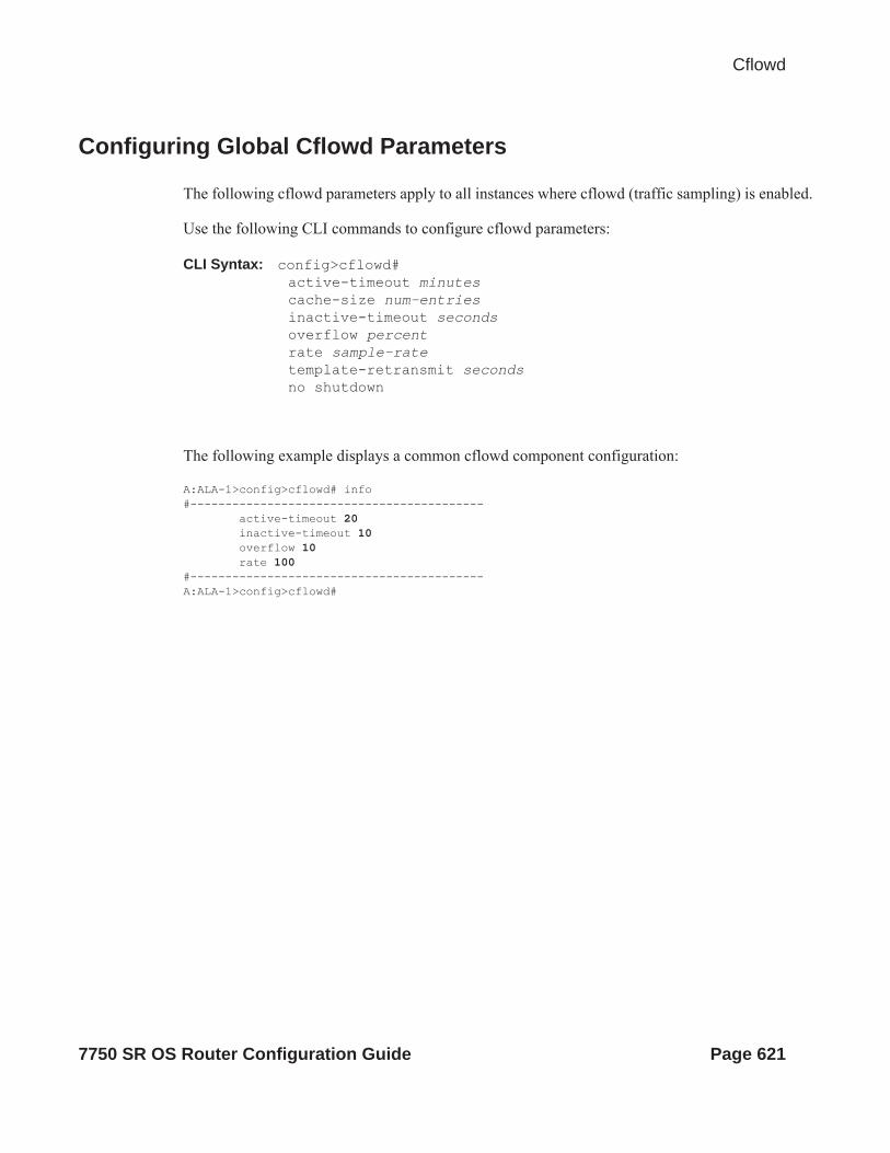
Cflowd
Configuring Global Cflowd Parameters
The following cflowd parameters apply to all instances where cflowd (traffic sampling) is enabled.
Use the following CLI commands to configure cflowd parameters:
CLI Syntax: config>cflowd#active-timeout minutescache-size num-entriesinactive-timeout secondsoverflow percentrate sample-ratetemplate-retransmit secondsno shutdown
The following example displays a common cflowd component configuration:
A:ALA-1>config>cflowd# info #------------------------------------------ active-timeout 20 inactive-timeout 10 overflow 10 rate 100#------------------------------------------A:ALA-1>config>cflowd#
7750 SR OS Router Configuration Guide Page 621
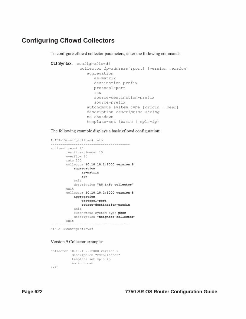
Configuring Cflowd Collectors
To configure cflowd collector parameters, enter the following commands:
CLI Syntax: config>cflowd#collector ip-address[:port] [version version]
aggregationas-matrixdestination-prefixprotocol-portrawsource-destination-prefixsource-prefix
autonomous-system-type [origin | peer]description description-stringno shutdowntemplate-set {basic | mpls-ip}
The following example displays a basic cflowd configuration:
A:ALA-1>config>cflowd# info-----------------------------------------active-timeout 20 inactive-timeout 10 overflow 10 rate 100 collector 10.10.10.1:2000 version 8 aggregation as-matrix raw exit description "AS info collector" exit collector 10.10.10.2:5000 version 8 aggregation protocol-port source-destination-prefix exit autonomous-system-type peer description "Neighbor collector" exit-----------------------------------------A:ALA-1>config>cflowd#
Version 9 Collector example:
collector 10.10.10.9:2000 version 9 description "v9collector" template-set mpls-ip no shutdownexit
Page 622 7750 SR OS Router Configuration Guide
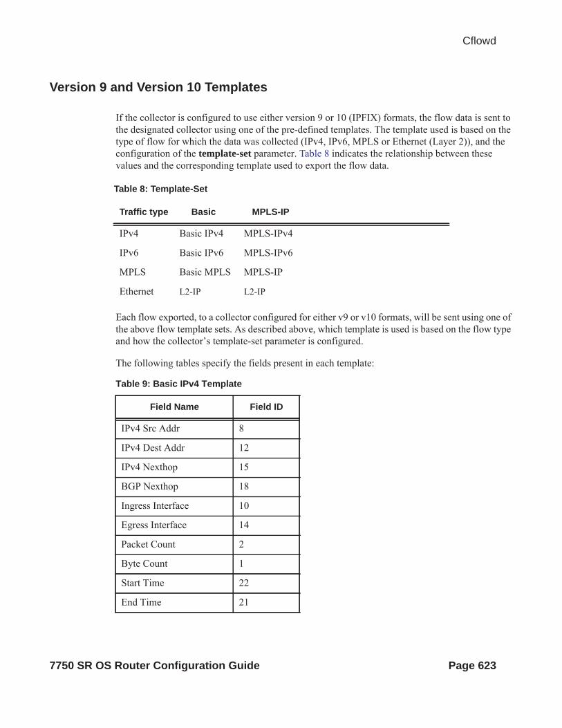
Cflowd
Version 9 and Version 10 Templates
If the collector is configured to use either version 9 or 10 (IPFIX) formats, the flow data is sent to the designated collector using one of the pre-defined templates. The template used is based on the type of flow for which the data was collected (IPv4, IPv6, MPLS or Ethernet (Layer 2)), and the configuration of the template-set parameter. Table 8 indicates the relationship between these values and the corresponding template used to export the flow data.
Each flow exported, to a collector configured for either v9 or v10 formats, will be sent using one of the above flow template sets. As described above, which template is used is based on the flow type and how the collector’s template-set parameter is configured.
The following tables specify the fields present in each template:
Table 8: Template-Set
Traffic type Basic MPLS-IP
IPv4 Basic IPv4 MPLS-IPv4
IPv6 Basic IPv6 MPLS-IPv6
MPLS Basic MPLS MPLS-IP
Ethernet L2-IP L2-IP
Table 9: Basic IPv4 Template
Field Name Field ID
IPv4 Src Addr 8
IPv4 Dest Addr 12
IPv4 Nexthop 15
BGP Nexthop 18
Ingress Interface 10
Egress Interface 14
Packet Count 2
Byte Count 1
Start Time 22
End Time 21
7750 SR OS Router Configuration Guide Page 623

Flow Start Milliseconds1 152
Flow End Milliseconds1 153
Src Port 7
Dest Port 11
Forwarding Status 89
TCP control Bits (Flags) 6
IPv4 Protocol 4
IPv4 TOS 5
IP version 60
ICMP Type & Code 32
Direction 61
BGP Source ASN 16
BGP Dest ASN 17
Source IPv4 Prefix Length
9
Dest IPv4 Prefix Length 13
1.Only sent to collectors configured forv10 format
Table 10: MPLS-IPv4 Template
Field Name Field ID
IPv4 Src Addr 8
IPv4 Dest Addr 12
IPv4 Nexthop 15
BGP Nexthop 18
Ingress Interface 10
Egress Interface 14
Table 9: Basic IPv4 Template (Continued)
Page 624 7750 SR OS Router Configuration Guide

Cflowd
Packet Count 2
Byte Count 1
Start Time 22
End Time 21
Flow Start Milliseconds1 152
Flow End Milliseconds 153
Src Port 7
Dest Port 11
Forwarding Status 89
TCP control Bits (Flags) 6
IPv4 Protocol 4
IPv4 TOS 5
IP version 60
ICMP Type & Code 32
Direction 61
BGP Source ASN 16
BGP Dest ASN 17
Source IPv4 Prefix Length
9
Dest IPv4 Prefix Length 13
MPLS Top Label Type 46
MPLS Top Label IPv4 Addr
47
MPLS Label 1 70
MPLS Label 2 71
MPLS Label 3 72
Table 10: MPLS-IPv4 Template (Continued)
Field Name Field ID
7750 SR OS Router Configuration Guide Page 625

MPLS Label 4 73
MPLS Label 5 74
MPLS Label 6 75
1.Only sent to collectors configured forv10 format
Table 11: Basic IPv6 Template
Field Name Field ID
IPv6 Src Addr 27
IPv6 Dest Addr 28
IPv6 Nexthop 62
IPv6 BGP Nexthop 63
IPv4 Nexthop 15
IPv4 BGP Nexthop 18
Ingress Interface 10
Egress Interface 14
Packet Count 2
Byte Count 1
Start Time 22
End Time 21
Flow Start Milliseconds1 152
Flow End Milliseconds1 153
Src Port 7
Dest Port 11
Forwarding Status 89
TCP control Bits (Flags) 6
Table 10: MPLS-IPv4 Template (Continued)
Field Name Field ID
Page 626 7750 SR OS Router Configuration Guide

Cflowd
Protocol 4
IPv6 Extension Hdr 64
IPv6 Next Header 193
IPv6 Flow Label 31
TOS 5
IP version 60
IPv6 ICMP Type & Code 139
Direction 61
BGP Source ASN 16
BGP Dest ASN 17
IPv6 Src Mask 29
IPv6 Dest Mask 30
1.Only sent to collectors configured forv10 format
Table 12: MPLS-IPv6 Template
Field Name Field ID
IPv6 Src Addr 27
IPv6 Dest Addr 28
IPv6 Nexthop 62
IPv6 BGP Nexthop 63
IPv4 Nexthop 15
IPv4 BGP Nexthop 18
Ingress Interface 10
Egress Interface 14
Packet Count 2
Table 11: Basic IPv6 Template
Field Name Field ID
7750 SR OS Router Configuration Guide Page 627

Byte Count 1
Start Time 22
End Time 21
Flow Start Milliseconds1 152
Flow End Milliseconds1 153
Src Port 7
Dest Port 11
Forwarding Status 89
TCP control Bits (Flags) 6
Protocol 4
IPv6 Extension Hdr 64
IPv6 Next Header 193
IPv6 Flow Label 31
TOS 5
IP version 60
IPv6 ICMP Type & Code 139
Direction 61
BGP Source ASN 16
BGP Dest ASN 17
IPv6 Src Mask 29
IPv6 Dest Mask 30
MPLS Label 1 70
MPLS Label 2 71
MPLS Label 3 72
Table 12: MPLS-IPv6 Template
Field Name Field ID
Page 628 7750 SR OS Router Configuration Guide

Cflowd
MPLS Label 4 73
MPLS Label 5 74
MPLS Label 6 75
1.Only sent to collectors configured forv10 format
Table 13: Basic MPLS Template
Field Name Field ID
Start Time 22
End Time 21
Flow Start Milliseconds1
1.Only sent to collectors configured forv10 format
152
Flow End Milliseconds1 153
Ingress Interface 10
Egress Interface 14
Packet Count 2
Byte Count 1
Direction 61
MPLS Label 1 70
MPLS Label 2 71
MPLS Label 3 72
MPLS Label 4 73
MPLS Label 5 74
MPLS Label 6 75
Table 12: MPLS-IPv6 Template
Field Name Field ID
7750 SR OS Router Configuration Guide Page 629

Table 14: MPLS-IP Template
Field Name Field ID
IPv4 Src Addr 8
IPv4 Dest Addr 12
IPv4 Nexthop 15
IPv6 Src Addr 27
IPv6 Dest Addr 28
IPv6 Nexthop 62
Ingress Interface 10
Egress Interface 14
Packet Count 2
Byte Count 1
Start Time 22
End Time 21
Flow Start Milliseconds1 152
Flow End Milliseconds1 153
Src Port 7
Dest Port 11
TCP control Bits (Flags) 6
IPv4 Protocol 4
IPv4 TOS 5
IP version 60
ICMP Type & Code 32
Direction 61
MPLS Top Label Type 46
MPLS Top Label IPv4 Addr 47
Page 630 7750 SR OS Router Configuration Guide

Cflowd
MPLS Label 1 70
MPLS Label 2 71
MPLS Label 3 72
MPLS Label 4 73
MPLS Label 5 74
MPLS Label 6 75
1.Only sent to collectors configured for v10format
Table 15: Ethernet (L2-IP) Flow Template1
Field Name Field ID
MAC Src Addr 56
MAC Dest Addr 80
Ingress Physical Interface 252
Egress Physical Interface 253
Dot1q VLAN ID 243
Dot1q Customer VLAN ID 245
Post Dot1q VLAN ID 254
Post Dot1q Customer VLAN Id
255
IPv4 Src Addr 8
IPv4 Dest Addr 12
IPv6 Src Addr 27
IPv6 Dest Addr 28
Packet Count 2
Byte Count 1
Table 14: MPLS-IP Template
Field Name Field ID
7750 SR OS Router Configuration Guide Page 631

Flow Start Milliseconds 152
Flow End Milliseconds 153
Src Port 7
Dest Port 11
TCP control Bits (Flags) 6
Protocol 4
IPv6 Option Header 64
IPv6 Next Header 196
IPv6 Flow Label 31
TOS 5
IP Version 60
ICMP Type Code 32
1.Ohe Ethernet (L2-IP) flow template is onlysupported and exported to IPFIX (v10) col-lectors.
Table 15: Ethernet (L2-IP) Flow Template1
Field Name Field ID
Page 632 7750 SR OS Router Configuration Guide

Cflowd
Enabling Cflowd on Interfaces and Filters
This section discusses the following cflowd configuration management tasks:
• Specifying Cflowd Options on an IP Interface on page 634 Interface Configurations on page 634 Service Interfaces on page 635
• Specifying Sampling Options in Filter Entries on page 636 Interface Configurations on page 634
• Dependencies on page 637
7750 SR OS Router Configuration Guide Page 633

Specifying Cflowd Options on an IP Interface
When cflowd is enabled on an interface, all packets forwarded by the interface are subject to analysis according to the global cflowd configuration and sorted according to the collector configuration(s).
Refer to Table 16, Cflowd Configuration Dependencies, on page 638 for configuration combinations.
When the cflowd interface option is configured in the config>router>interface context, the following requirements must be met to enable traffic sampling on the specific interface:
1. Cflowd must be enabled.2. At least one cflowd collector must be configured and enabled.3. The interface>cflowd interface option must be selected. For configuration information,
refer to the Filter Policy Overview section of the 7750 SR OS Router Configuration Guide.
4. To omit certain types of traffic from being sampled when the interface sampling is enabled, the config>filter>ip-filter>entry>interface-disable-sample option may be enabled via an ip-filter or ipv6-filter. The filter must be applied to the service or network interface on which the traffic to be omitted is to ingress the system.
Interface Configurations
CLI Syntax: config>router>if#cflowd {acl|interface}no cflowd
Depending on the option selected, either acl or interface, cflowd extracts traffic flow samples from an IP filter or an interface for analysis. All packets forwarded by the interface are analyzed according to the cflowd configuration.
The acl option must be selected in order to enable traffic sampling on an IP filter. Cflowd (filter-sample) must be enabled in at least one IP filter entry.
The interface option must be selected in order to enable traffic sampling on an interface. If cflowd is not enabled (no cflowd) then traffic sampling will not occur on the interface.
Page 634 7750 SR OS Router Configuration Guide

Cflowd
Service Interfaces
CLI Syntax: config>service>vpls service-id# interface ip-int-namecflowd {acl|interface}
When enabled on a service interface, cflowd collects routed traffic flow samples through a router for analysis. Cflowd is supported on IES and VPRN services interfaces only. Layer 2 traffic is excluded. All packets forwarded by the interface are analyzed according to the cflowd configuration. On the interface level, cflowd can be associated with a filter (ACL) or an IP interface.
7750 SR OS Router Configuration Guide Page 635

Specifying Sampling Options in Filter Entries
Packets are matched against filter entries to determine acceptability. With cflowd, only the first packet of a flow is compared. If the first packet matches the filter criteria, then an entry is added to the cflowd cache. Subsequent packets in the same flow are also sampled based on the cache entry.
Since a filter can be applied to more than one interface (when configured with a scope template), the interface-disable-sample option is intended to enable or disable traffic sampling on an interface-by-interface basis. The command can be enabled or disabled as needed instead creating numerous filter versions.
To enable for filtr traffic sampling, the following requirements must be met::
1. Cflowd must be enabled globally.2. At least one cflowd collector must be configured and enabled.3. On the IP interface being used, the interface>cflowd acl option must be selected. (See
Interfcace Configuration) For configuration information, refer to the IP Router Confguration Overview section of the 7750 SR OS Router Configuration Guide.
4. On the IP filter being used, the entry>filter-sample option must be explicitly enabled for the entries matching the traffic that should be sampled. The default is no filter-sample. (See Filter Configuration for more information).
5. The filter must be applied to a service or a network interface. The service or port must be enabled and operational.
Filter Configurations
CLI Syntax: config>filter>ip-filter>entry#[no] filter-sample[no] interface-disable-sample
When a filter policy is applied to a service or a network interface, sampling can be configured so that traffic matching the associated IP filter entry is sampled when the IP interface is set to cflowd ACL mode and the filter-sample command is enabled. If cflowd is either not enabled (no filter-sample) or set to the cflowd interface mode, then sampling does not occur.
When the interface-disable-sample command is enabled, then traffic matching the associated IP filter entry is not sampled if the IP interface is set to cflowd ACL mode.
Page 636 7750 SR OS Router Configuration Guide
Cflowd
Dependencies
In order for cflowd to be operational, the following requirements must be met:
• Cflowd must be enabled on a global level. If cflowd is disabled, any traffic sampling instances are also disabled.
• At least one collector must be configured and enabled in order for traffic sampling to occur on an enabled entity.
• If a specific collector UDP port is not identified then, by default, flows are sent to port 2055.
Cflowd can also be dependent on the following entity configurations:
• Interface Configurations on page 634• Service Interfaces on page 635• Filter Configurations on page 636
Depending on the combination of interface and filter entry configurations determine if and when flow sampling occurs. Table 16 displays the expected results when specific features are enabled and disabled.
7750 SR OS Router Configuration Guide Page 637

Table 16: Cflowd Configuration Dependencies
Interface Setting router>interface cflowd [acl | interface]
Setting
Commandip-filter entry
Expected Results
IP-filter mode ACL filter-sampled Traffic matching is sampled at specified rate.
IP-filter mode ACL no filter-sampled No traffic is sampled on this interface.
IP-filter mode or cflowd not enabled on interface
ACL interface-disable-sample
Command is ignored. No sampling occurs.
Interface mode interface interface-disable-sample
Traffic matching this IP filter entry is not sampled.
Interface mode interface none All IP traffic ingressing the interface is subject to sampling.
Interface mode interface filter sampled Filter level action is ignored. All traffic ingressing the interface is subject to sampling.
Page 638 7750 SR OS Router Configuration Guide

Cflowd
Cflowd Configuration Management TasksThis section discusses the following cflowd configuration management tasks:
• Modifying Global Cflowd Components on page 639• Modifying Cflowd Collector Parameters on page 640
Modifying Global Cflowd Components
Cflowd parameter modifications apply to all instances where cflowd or traffic sampling is enabled. Changes are applied immediately. Use the following cflowd commands to modify global cflowd parameters:
CLI Syntax: config>cflowd#active-timeout minutesno active-timeout cache-size num-entriesno cache-size inactive-timeout secondsno inactive-timeout overflow percentno overflowrate sample-rateno rate[no] shutdowntemplate-retransmit secondsno template-retransmit
The following example displays the cflowd command usage to modify configuration parameters:
Example: config>cflowd# active-timeout 60config>cflowd# no inactive-timeoutconfig>cflowd# overflow 2config>cflowd# rate 10
The following example displays the common cflowd component configuration:
A:ALA-1>config>cflowd# info #------------------------------------------ active-timeout 60 overflow 2 rate 10#------------------------------------------A:ALA-1>config>cflowd#
7750 SR OS Router Configuration Guide Page 639

Modifying Cflowd Collector Parameters
Use the following commands to modify cflowd collector and aggregation parameters:
CLI Syntax: config>cflowd#collector ip-address[:port] [version version]no collector ip-address[:port]
[no] aggregation[no] as-matrix[no] destination-prefix[no] protocol-port[no] raw[no] source-destination-prefix[no] source-prefix
[no] autonomous-system-type [origin | peer][no] description description-string[no] shutdowntemplate-set {basic | mpls-ip | l2-ip}
If a specific collector UDP port is not identified then, by default, flows are sent to port 2055.
The following displays basic cflowd modifications:
A:ALA-1>config>cflowd# info-----------------------------------------
active-timeout 60 overflow 2 rate 10 collector 10.10.10.1:2000 version 5 description "AS info collector" exit collector 10.10.10.2:5000 version 8 aggregation source-prefix raw exit description "Test collector" exit-----------------------------------------A:ALA-1>config>cflowd#
Page 640 7750 SR OS Router Configuration Guide
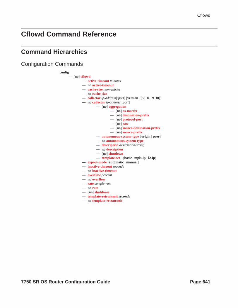
Cflowd
Cflowd Command Reference
Command Hierarchies
Configuration Commandsconfig
— [no] cflowd— active-timeout minutes— no active-timeout— cache-size num-entries— no cache-size— collector ip-address[:port] [version {[5 | 8 | 9 |10]}— no collector ip-address[:port]
— [no] aggregation— [no] as-matrix— [no] destination-prefix— [no] protocol-port— [no] raw— [no] source-destination-prefix— [no] source-prefix
— autonomous-system-type {origin | peer}— no autonomous-system-type— description description-string— no description— [no] shutdown— template-set {basic | mpls-ip | l2-ip}
— export-mode [automatic | manual]— inactive-timeout seconds— no inactive-timeout— overflow percent— no overflow— rate sample-rate— no rate— [no] shutdown— template-retransmit seconds— no template-retransmit
7750 SR OS Router Configuration Guide Page 641

Show Commandsshow
— cflowd— collector [ip-address[:port]] [detail]— interface [ip-int-name | ip-address]— status
Tools Commandstools
— dump— cflowd
— top-protocols [clear]— top-flows [ipv4 | ipv6 | mpls] [clear]— packet-size [ipv4 | ipv6] [clear]
Clear Commandsclear
— cflowd
Page 642 7750 SR OS Router Configuration Guide

Cflowd
Cflowd Configuration Commands
Global Commands
cflowd
Syntax [no] cflowd
Context config>cflowd
Description This command creates the context to configure cflowd.
The no form of this command removes all configuration under cflowd including the deletion of all configured collectors. This can only be executed if cflowd is in a shutdown state.
Default no cflowd
active-timeout
Syntax active-timeout minutesno active-timeout
Context config>cflowd
Description This command configures the maximum amount of time before an active flow is aged out of the active cache. If an individual flow is active for this amount of time, the flow is aged out and a new flow will be created on the next packet sampled for that flow.
Note: Existing flows do not inherit the new active-timeout value if this parameter is changed while cflowd is active. The active-timeout value for a flow is set when the flow is first created in the active cache table and does not change dynamically.
The no form of this command resets the inactive timeout back to the default value.
Default 30
Parameters minutes — The value expressed in minutes before an active flow is exported.
Values 1 — 600
7750 SR OS Router Configuration Guide Page 643

cache-size
Syntax cache-size num-entriesno cache-size
Context config>cflowd
Description This command specifies the maximum number of active flows to maintain in the flow cache table.
The no form of this command resets the number of active entries back to the default value.
Default 65536 (64K)
Parameters num-entries — The number of entries maintained in the cflowd cache.
Values 1000 - 1000000 (SF/CPM5)1000 - 250000 (SF/CPM3 and 7750 SR-c12/4)1000 - 128k (all other platforms)
collector
Syntax collector ip-address[:port] {version [ 5 | 8 | 9 | 10]}no collector
Context config>cflowd
Description This command defines a flow data collector for cflowd data. The IP address of the flow collector must be specified. The UDP port number is an optional parameter. If it is not set, the default of 2055 is used for all collector versions. To connect to a IPFIX (version 10) collector using the IPFIX default port, specify port 4739 when configuring the collector. The version must be specified. A maximum of 5 collectors can be configured.
The no form of this command removes the flow collector definition from the config and stops the export of data to the collector. The collector needs to be shutdown to be deleted.
Default none
Parameters ip-address — Specifies the address of a remote Cflowd collector host to receive the exported Cflowd data.
Values <ip-address[:port]> : ip-address - a.b.c.d[:port] (IPv4)x:x:x:x:x:x:x:x (IPv6)[x:x:x:x:x:x:x:x]:port (IPv6)x - [0..FFFF]H
port — Specifies the UDP port number on the remote Cflowd collector host to receive the exported Cflowd data.
Values 1— 65535
Default 2055
Page 644 7750 SR OS Router Configuration Guide

Cflowd
version — Specifies the version of the flow data collector.
Values Netflow v5, v8, v9, v10 (IPFIX) format
Default 5
aggregation
Syntax [no] aggregation
Context config>cflowd>collector
Description This command configures the type of aggregation scheme to be exported.
Specifies the type of data to be aggregated and to the collector.
To configure aggregation, you must decide which type of aggregation scheme to configure: autonomous system, destination prefix, protocol port, raw, source destination, or source prefix.
This can only be configured if the collector version is configured as V8.
The no form of this command removes all aggregation types from the collector configuration.
Default no aggregation
as-matrix
Syntax [no] as-matrix
Context config>cflowd>collector>aggregation
Description This command specifies that the aggregation data should be based on autonomous system (AS) information. An AS matrix contains packet and byte counters for traffic from either source-destination autonomous systems or last-peer to next-peer autonomous systems.
The no form of this command removes this type of aggregation from the collector configuration.
Default no as-matrix
destination-prefix
Syntax [no] destination-prefix
Context config>cflowd>collector>aggregation
Description This command specifies that the aggregation data is based on destination prefix information.
The no form removes this type of aggregation from the collector configuration.
Default none
7750 SR OS Router Configuration Guide Page 645

protocol-port
Syntax [no] protocol-port
Context config>cflowd>collector>aggregation
Description This command specifies that flows be aggregated based on the IP protocol, source port number, and destination port number.
The no form of this command removes this type of aggregation from the collector configuration.
Default none
raw
Syntax [no] raw
Context config>cflowd>collector>aggregation
Description This command configures raw (unaggregated) flow data to be sent in Version 5.
The no form of this command removes this type of aggregation from the collector configuration.
Default none
source-destination-prefix
Syntax [no] source-destination-prefix
Context config>cflowd>collector>aggregation
Description This command configures cflowd aggregation based on source and destination prefixes.
The no form of this command removes this type of aggregation from the collector configuration.
Default none
source-prefix
Syntax [no] source-prefix
Context config>cflowd>collector>aggregation
Description This command configures cflowd aggregation based on source prefix information.
The no form of this command removes this type of aggregation from the collector configuration.
Default none
Page 646 7750 SR OS Router Configuration Guide

Cflowd
autonomous-system-type
Syntax autonomous-system-type {origin | peer}no autonomous-system-type
Context config>cflowd>collector
Description This command defines whether the autonomous system (AS) information included in the flow data is based on the originating AS or external peer AS of the routes.
This option is only allowed if the collector is configured as Version 5 or Version 8.
The no form of this command resets the AS type to the default value.
Default autonomous-system-type origin
Parameters origin — Specifies that the AS information included in the flow data is based on the originating AS.
peer — Specifies that the AS information included in the flow data is based on the peer AS.
description
Syntax description description-stringno description
Context config>cflowd>collector
Description This command creates a text description stored in the configuration file for a configuration context.
The no form of this command removes the description string from the context.
Default No description is associated with the configuration context.
Parameters description-string — The description character string. Allowed values are any string up to 80 charac-ters long composed of printable, 7-bit ASCII characters. If the string contains special characters (#, $, spaces, etc.), the entire string must be enclosed within double quotes.
shutdown
Syntax [no] shutdown
Context config>cflowdconfig>cflowd>collector
Description This command administratively disables an entity. When disabled, an entity does not change, reset, or remove any configuration settings or statistics.
The operational state of the entity is disabled as well as the operational state of any entities contained within. Many objects must be shut down before they may be deleted.
The no form of this command administratively enables an entity.
7750 SR OS Router Configuration Guide Page 647

Unlike other commands and parameters where the default state is not indicated in the configuration file. The shutdown and no shutdown states are always indicated in system generated configuration files.
template-set
Syntax template-set {basic | mpls-ip | l2-ip}
Context config>cflowd>collector
Description This command specifies the set of templates sent to the collector when using cflowd Version 9 or Version 10.
Default basic
Parameters basic — Basic flow data is sent.
mpls-ip — Extended flow data is sent that includes IP and MPLS flow information.
l2-ip — Extended flow data is sent that includes Layer 2 (ethernet) and IP flow information.This template is only applicable for v10(IPFIX) collectors.
export-mode
Syntax export-type [automatic | manual]
Context config>cflowd
Description This command can be used to control how exports are generated by the cflowd process. The default behavior is for flow data to be exported automatically based on the active and inactive time-out values. The alternative mode is manual in which case flow data is only exported when the command “tools perform cflowd manual-export” is issued. The only exception is if the cflowd cache overflows, in which case the normal automatic export process is used.
Default export-mode automatic
Parameters automatic — Cflowd flow data is automatically generated.
manual — Cflowd flow data is exported only when manual triggered.
inactive-timeout
Syntax inactive-timeout secondsno inactive-timeout
Context config>cflowd
Description This command specifies the amount of time, in seconds, that must elapse without a packet matching a flow in order for the flow to be considered inactive.
Page 648 7750 SR OS Router Configuration Guide

Cflowd
The no form of this command resets the inactive timeout back to the default of 15 seconds.
Note: Existing flows will not inherit the new inactive-timeout value if this parameter is changed while cflowd is active. The inactive-timeout value for a flow is set when the flow is first created in the active cache table and does not change dynamically.
Default 15
Parameters seconds — Specifies the amount of time, in seconds, that must elapse without a packet matching a flow in order for the flow to be considered inactive.
Values 10 — 600
overflow
Syntax overflow percentno overflow
Context config>cflowd
Description This command specifies the percentage of the flow cache entries removed when the maximum number of entries is exceeded. The entries removed are the entries that have not been updated for the longest amount of time.
The no form of this command resets the number of entries cleared from the flow cache on overflow to the default value.
Default 1 %
Parameters percent — Specifies the percentage of the flow cache entries removed when the maximum number of entries is exceeded.
Values 1 — 50 percent
rate
Syntax rate sample-rateno rate
Context config>cflowd
Description This command specifies the rate (N) at which traffic is sampled and sent for flow analysis. A packet is sampled every N packets; for example, when sample-rate is configured as 1, then all packets are sent to the cache. When sample-rate is configured as 100, then every 100th packet is sent to the cache.
The no form of this command resets the sample rate to the default value.
Default 1000
Parameters sample-rate — Specifies the rate at which traffic is sampled.
Values 1 — 10000
7750 SR OS Router Configuration Guide Page 649
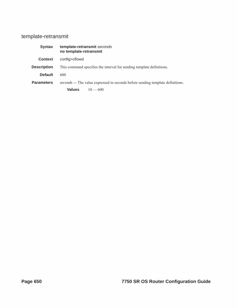
template-retransmit
Syntax template-retransmit secondsno template-retransmit
Context config>cflowd
Description This command specifies the interval for sending template definitions.
Default 600
Parameters seconds — The value expressed in seconds before sending template definitions.
Values 10 — 600
Page 650 7750 SR OS Router Configuration Guide

Cflowd
Show Commands
collector
Syntax collector [ip-addr[:port]] [detail]
Context show>cflowd
Description This command displays administrative and operational status of data collector configuration.
Parameters ip-addr — Display only information about the specified collector IP address.
Default all collectors
:port — Display only information the collector on the specified UDP port.
Default all UDP ports
Values 1 — 65535
detail — Displays details about either all collectors or the specified collector.
Output cflowd Collector Output — The following table describes the show cflowd collector output fields:
Table 17: Show Cflowd Collector Output Fields
Label Description
Host Address The IP address of a remote Cflowd collector host to receive the exported Cflowd data.
Port The UDP port number on the remote Cflowd collector host to receive the exported Cflowd data.
AS Type The style of AS reporting used in the exported flow data.
origin — Reflects the endpoints of the AS path which the flow is following.
peer — Reflects the AS of the previous and next hops for the flow.
Version Specifies the configured version for the associated collector.
Admin The desired administrative state for this Cflowd remote collector host.
Oper The current operational status of this Cflowd remote collector host.
Recs Sent The number of Cflowd records that have been transmitted to this remote collector host.
Collectors The total number of collectors using this IP address.
7750 SR OS Router Configuration Guide Page 651

Sample Output
A:SR1 # show cflowd collector detail===============================================================================Cflowd Collectors (detail)===============================================================================Address : 138.120.135.103Port : 2055Description : Test v9 CollectorVersion : 9Admin State : upOper State : upPackets Sent : 51Last Changed : 09/03/2009 17:24:04Last Pkt Sent : 09/03/2009 18:07:10Template Set : Basic-------------------------------------------------------------------------------Traffic Type Template Sent Sent Open Errors-------------------------------------------------------------------------------IPv4 09/03/2009 18:07:29 51 1 0MPLS No template sent 0 0 0IPv6 No template sent 0 0 0===============================================================================
A:R51-CfmA# show cflowd collector
===============================================================================Cflowd Collectors ===============================================================================Host Address Port Version AS Type Admin Oper Sent -------------------------------------------------------------------------------138.120.135.103 2055 v5 peer up up 1380 records 138.120.135.103 9555 v8 origin up up 90 records 138.120.135.103 9996 v9 - up up 0 packets 138.120.214.224 2055 v5 origin up up 1380 records -------------------------------------------------------------------------------Collectors : 4===============================================================================
Table 18: Show Cflowd Collector Detailed Output Fields
Label Description
Address The IP address of a remote Cflowd collector host to receive the exported Cflowd data.
Port The UDP port number on the remote Cflowd collector host to receive the exported Cflowd data.
Description A user-provided descriptive string for this Cflowd remote collector host.
Version The version of the flow data sent to the collector.
Page 652 7750 SR OS Router Configuration Guide

Cflowd
A:R51-CfmA# show cflowd collector detail ===============================================================================Cflowd Collectors (detail)===============================================================================Address : 138.120.135.103Port : 2055Description : Test v5 CollectorVersion : 5AS Type : peerAdmin State : upOper State : up
AS Type The style of AS reporting used in the exported flow data.
origin — Reflects the endpoints of the AS path which the flow is following.
peer — Reflects the AS of the previous and next hops for the flow.
Admin State The desired administrative state for this Cflowd remote collector host.
Oper State The current operational status of this Cflowd remote collector host.
Records Sent The number of Cflowd records that have been transmitted to this remote collector host.
Last Changed The time when this row entry was last changed.
Last Pkt Sent The time when the last Cflowd packet was sent to this remote collector host.
Aggregation Type The bit mask which specifies the aggregation scheme(s) used to aggre-gate multiple individual flows into an aggregated flow for export to this remote host collector.
none — No data will be exported for this remote collector host.
raw — Flow data is exported without aggregation in version 5 format.
All other aggregation types use version 8 format to export the flow data to this remote host collector.
Collectors The total number of collectors using this IP address.
Sent The number of packets with flow date sent to the associated collector.
Open This counter shows the number of partially filled packets which have some flow data but are not yet filled or have been timed out (60 sec-onds maximum).
Error This counter increments when there was an error during exporting of the collector packet. The most common reason will be a UDP unreach-able destination for the configured collector.
Table 18: Show Cflowd Collector Detailed Output Fields (Continued)
Label Description (Continued)
7750 SR OS Router Configuration Guide Page 653

Records Sent : 1260Last Changed : 09/03/2009 17:24:04Last Pkt Sent : 09/03/2009 18:07:10------------------------------------------------------------------------------- Sent Open Errors ------------------------------------------------------------------------------- 42 0 0===============================================================================Address : 138.120.135.103Port : 9555 Description : Test v8 CollectorVersion : 8AS Type : originAdmin State : upOper State : upRecords Sent : 82Last Changed : 09/03/2009 17:24:04Last Pkt Sent : 09/03/2009 18:06:41-------------------------------------------------------------------------------Aggregation Type Status Sent Open Errors -------------------------------------------------------------------------------as-matrix Disabled 0 0 0protocol-port Disabled 0 0 0source-prefix Enabled 21 0 0destination-prefix Enabled 21 0 0source-destination-prefix Disabled 0 0 0raw Disabled 0 0 0===============================================================================Address : 138.120.135.103Port : 9996Description : Test v9 CollectorVersion : 9Admin State : upOper State : upPackets Sent : 51Last Changed : 09/03/2009 17:24:04Last Pkt Sent : 09/03/2009 18:07:10Template Set : Basic-------------------------------------------------------------------------------Traffic Type Template Sent Sent Open Errors -------------------------------------------------------------------------------IPv4 09/03/2009 18:07:29 51 1 0MPLS No template sent 0 0 0IPv6 No template sent 0 0 0===============================================================================A:R51-CfmA#
interface
Syntax interface [ip-addr | ip-int-name]
Context show>cflowd
Description Displays the administrative and operational status of the interfaces with cflowd enabled.
Parameters ip-addr — Display only information for the IP interface with the specified IP address.
Default all interfaces with cflowd enabled.
Page 654 7750 SR OS Router Configuration Guide

Cflowd
ip-int-name — Display only information for the IP interface with the specified name.
Default all interfaces with cflowd enabled.
Output cflowd Interface Output — The following table describes the show cflowd interface output fields.
Sample Output
B:sr-002# show cflowd interface [ip-addr | ip-int-name] ===============================================================================Cflowd Interfaces===============================================================================Interface Router IF Index Mode Admin IPv4 Address Oper IPv4 IPv6 Address Oper IPv6-------------------------------------------------------------------------------ipv4ipv6NamedIf Base 381 intf/ing Up 5.5.5.5/24 Up 55::55/128 Upipv4NamedIf 5 254 acl-egr Up 10.10.10.10/24 Up N/A Downipv6NamedIf Base 380 i/f-both Up N/A Down 1234:5678::9/128 Up-------------------------------------------------------------------------------Interfaces : 3===============================================================================
Label Description
Interface Displays the physical port identifier.
IPv4 Address Displays the primary IPv4 address for the associated IP interface.
IPv6 Address Displays the primary IPv6 address for the associated IP interface.
Router Displays the virtual router index (Base = 0).
IF Index Displays the Global IP interface index.
Mode Displays the cflowd sampling type and direction.intf — Interface based samplingacl — ACL based samplingingr — Ingress samplingegr — Egress samplingboth — Both ingress and egress sampling
Admin Displays the administrative state of the interface.
Opr-IPv4 Displays the operational state for IPv4 sampling.
Opr-IPv6 Displays the operational state for IPv6 sampling.
7750 SR OS Router Configuration Guide Page 655

B:sr-002# show cflowd interface 11.10.1.2===============================================================================Cflowd Interfaces===============================================================================Interface: To_Sr1IP address: 11.10.1.2/24Admin/Oper state: Up/UpSampling Mode: (ingress | egress | both)Total Flows seen: 1302000Pkts sampled (ingress/egress) : 60103/70102 Bytes sampled (ingress/egress) : 6010300/7010200 Active flows (ingress/egress) : 6010/7010
B:sr-002# show cflowd interface===============================================================================Cflowd Interfaces===============================================================================Interface IP Address Mode Admin Oper-------------------------------------------------------------------------------To_Sr1 1.10.1.2/24 Interface Up UpTo_C2 1.12.1.2/24 Interface Up UpTo_Cisco_7600 1.13.1.2/24 Interface Up UpTo_E 1.11.1.2/24 Interface Up UpTo_G2 150.153.1.1/24 Interface Up UpTo_Sr1_Sonet 150.140.1.2/24 Interface Up DownMain 120.1.1.1/24 Filter Down DownNew 120.2.1.1/24 Filter Up Up-------------------------------------------------------------------------------Interfaces : 8===============================================================================B:sr12-002#
status
Syntax status
Context show>cflowd
Description This command displays basic information regarding the administrative and operational status of cflowd.
Output cflowd Status Output — The following table describes the show cflowd status output fields:
Table 19: Cflowd Status Output
Label Description
Cflowd Admin Sta-tus
The desired administrative state for this Cflowd remote collector host.
Cflowd Oper Status The current operational status of this Cflowd remote collector host.
Page 656 7750 SR OS Router Configuration Guide

Cflowd
Sample Output
sr1# show cflowd status===============================================================================Cflowd Status===============================================================================Cflowd Admin Status : Enabled
Active Timeout The maximum amount of time, in minutes, before an active flow will be exported. If an individual flow is active for this amount of time, the flow is exported and a new flow is created.
Inactive Timeout Inactive timeout in seconds.
Template Retrans-mit
The time in seconds before template definitions are sent.
Cache Size The maximum number of active flows to be maintained in the flow cache table.
Overflow The percentage number of flows to be flushed when the flow cache size has been exceeded.
Sample Rate The rate at which traffic is sampled and forwarded for Cflowd analysis. one (1) — All packets are analyzed. 1000 (default) — Every 1000th packet is analyzed.
Active Flows The current number of active flows being collected.
Total Pkts Rcvd The rate at which traffic is sampled and forwarded for Cflowd analysis.
Total Pkts Dropped The total number of packets dropped.
Aggregation Info:
Type The type of data to be aggregated and to the collector.
Status enabled — Specifies that the aggregation type is enabled.
disabled — Specifies that the aggregation type is disabled.
Sent The number of packets with flow date sent to the associated collector.
Open This counter shows the number of partially filled packets which have some flow data but are not yet filled or have been timed out (60 sec-onds maximum).
Error This counter increments when there was an error during exporting of the collector packet. The most common reason will be a UDP unreach-able destination for the configured collector.
Overflow events The number of times the active cache overflowed.
Dropped Flows Equal to “total flows trashed” in cflowdStatsTotal.
Table 19: Cflowd Status Output (Continued)
Label Description (Continued)
7750 SR OS Router Configuration Guide Page 657

Cflowd Oper Status : EnabledActive Timeout : 1 minutesInactive Timeout : 30 secondsTemplate Retransmit : 60 secondsCache Size : 65536 entriesOverflow : 1%Sample Rate : 1Active Flows : 34000Overflow events 10 Dropped Flows: 0 Pkts Rcvd : 801600Total Pkts Dropped : 0 Raw Times flow created 160000 Times flow matched 224428382 Total flows flushed 150000 ===============================================================================Version Info===============================================================================Version Status Sent Open Errors-------------------------------------------------------------------------------5 Enabled 92 0 08 Enabled 46 0 09 Enabled 56 1 010 Enabled 39 1 0===============================================================================
===============================================================================Cflowd Status===============================================================================Cflowd Admin Status : EnabledCflowd Oper Status : EnabledActive Timeout : 1 minutesInactive Timeout : 30 secondsTemplate Retransmit : 60 secondsCache Size : 65536 entriesOverflow : 1%Sample Rate : 1Active Flows : 34Total Pkts Rcvd : 801600Total Pkts Dropped : 0
===============================================================================Version Info===============================================================================Version Status Sent Open Errors ------------------------------------------------------------------------------- 5 Enabled 92 0 0 8 Enabled 46 0 0 9 Enabled 56 1 0 10 Enabled 39 1 0 ===============================================================================
Page 658 7750 SR OS Router Configuration Guide

Cflowd
Tools Commands
top-protocols
Syntax top-protocols
Context tools>dump>cflowd [clear]
Description This command displays the summary information for the top 20 protocol traffic seen in the cflowd cache. All statistics are calculated based on the data collected since the last clearing of the cflowd stats with clear keyword for this command.
If the clear optional keyword is given, then the top-flows are displayed, and then this cache is cleared.
Output Tools Dump Cflowd Top-protocols Output — The following table describes the tools dump cflowd top-protocols output fields:
Table 20: Tools Dump Cflowd Output Fields
Label Description
Protocol ID Displays the IPv4 or IPv6 protocol type.This will either print the well known protocol name or the decimal pro-tocol number.
Total Flows Displays the total number of flows recorded since the last clearing of cflowd statistics with this protocol type.
Flows/Sec Displays the average number of flows detected for the associated pro-tocol type.(Total flows / number of seconds since last clear)
Packets/Flow Displays the average number of packets per flow.(Total number of packets / total flows)
Bytes/Pkts Displays the average number of bytes per packet for the associated protocol type.(Total number of bytes for the associated protocol / total number of packets seen for the associated protocol)
Packets/Sec Displays the average number of packets seen for the associated proto-col type.(Number of packets / time since last clear)
Duration/Flow Displays the average lifetime of a flow for the associated protocol type.(Number of seconds since last clear / total flows)
Bandwidth Total (%)
Displays the percentage of bandwidth consumed by the associated pro-tocol type.(Total protocol bytes / total bytes of all flows)
7750 SR OS Router Configuration Guide Page 659
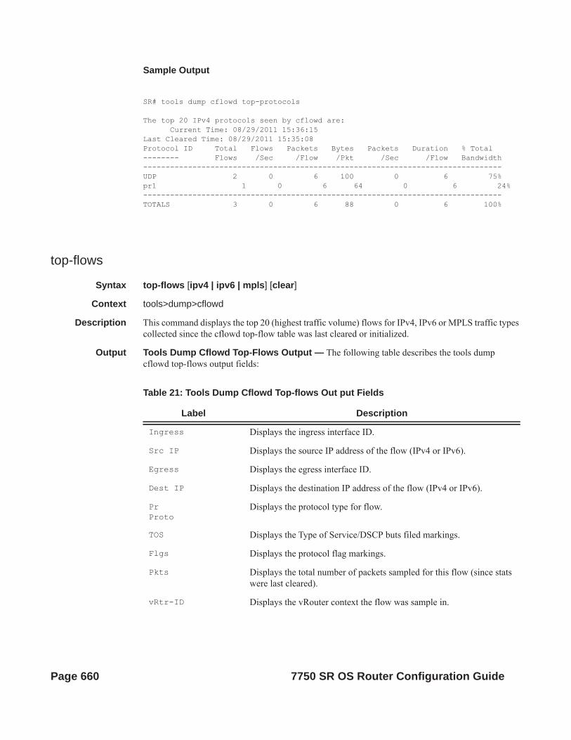
Sample Output
SR# tools dump cflowd top-protocols
The top 20 IPv4 protocols seen by cflowd are: Current Time: 08/29/2011 15:36:15Last Cleared Time: 08/29/2011 15:35:08Protocol ID Total Flows Packets Bytes Packets Duration % Total-------- Flows /Sec /Flow /Pkt /Sec /Flow Bandwidth--------------------------------------------------------------------------------UDP 2 0 6 100 0 6 75%pr1 1 0 6 64 0 6 24%--------------------------------------------------------------------------------TOTALS 3 0 6 88 0 6 100%
top-flows
Syntax top-flows [ipv4 | ipv6 | mpls] [clear]
Context tools>dump>cflowd
Description This command displays the top 20 (highest traffic volume) flows for IPv4, IPv6 or MPLS traffic types collected since the cflowd top-flow table was last cleared or initialized.
Output Tools Dump Cflowd Top-Flows Output — The following table describes the tools dump cflowd top-flows output fields:
Table 21: Tools Dump Cflowd Top-flows Out put Fields
Label Description
Ingress Displays the ingress interface ID.
Src IP Displays the source IP address of the flow (IPv4 or IPv6).
Egress Displays the egress interface ID.
Dest IP Displays the destination IP address of the flow (IPv4 or IPv6).
PrProto
Displays the protocol type for flow.
TOS Displays the Type of Service/DSCP buts filed markings.
Flgs Displays the protocol flag markings.
Pkts Displays the total number of packets sampled for this flow (since stats were last cleared).
vRtr-ID Displays the vRouter context the flow was sample in.
Page 660 7750 SR OS Router Configuration Guide

Cflowd
Sample Output
1 2 3 4 5 6 7 812345678901234567890123456789012345678901234567890123456789012345678901234567890Sr1# tools dump cflowd top-flows ipv4
Ingress i/f SrcIP Egress i/f DstIP Pr TOS Flgs Pkts vRtr-ID S-Port Msk AS D-Port Msk AS NextHop Avg Pkt Size Active----------------------------------------------------------------------------------1000 52.52.52.1 2001 123.123.123.122 0x01 55 0x10 3748 10201 0000 /8 50 0000 /8 40 202.120.130.2 220 3600……
1 2 3 4 5 6 7 812345678901234567890123456789012345678901234567890123456789012345678901234567890Sr1# tools dump cflowd top-flows ipv6SrcIP (up to IPv6) Ingress i/f Src Port vRtr ID ToS DstIP (upto IPv6) Egress i/f Dst Port Proto Flags Nexthop (uptoIPv6) Total Pkts Avg Pkt Active(sec) 2001:0db8:85a3:0000:0000:8a2e:0370:7334 60005 10020 0 0x122001:0db8:85a3:0000:0000:8a2e:0280:1234 60325 20010 17 0x23 2001:0db8:85a3:0000:0000:8a2e:1234:5678 1234567890 1500 13600 ……
S-PortSrc Port
Displays the source protocol port number.
Msk Displays the route prefix length for route to source IP address.
AS Displays the Autonomous Systems number for the source route (the AS is either originating AS or peer AS depending on cflowd configura-tion).
D-PortDst Port
DIsplays the destination protocol port number.
Msk Displays the route prefix length for route to destination IP address (Forwarding route).
AS Displays the Autonomous Systems number for the destination route (the AS is either originating AS or peer AS depending on cflowd con-figuration)
Nexthop Displays the next-hop address used to forward traffic associated with the flow.
Avg pkt size Displays the average packet size of a sampled traffic associated with this flow (total number of packets sampled / total number of packets sampled).
Active Displays the number of seconds the flow has been active.
Table 21: Tools Dump Cflowd Top-flows Out put Fields
Label Description
7750 SR OS Router Configuration Guide Page 661

1 2 3 4 5 6 7 812345678901234567890123456789012345678901234567890123456789012345678901234567890Sr1# tools dump cflowd top-flows mplsLabel-1 Label-2 Label-3 Label-4 Total Pkts Avg Pkt Active(s) SrcIP (up to IPv6) Ingress i/f Src Port ToS DstIP (upto IPv6) Egress i/f Dst Port Proto Flags --------------------------------------------------------------------------------
packet-size
Syntax packet-size [ipv4 | ipv6] [clear]
Context tools>dump>cflowd
Description This command displays packet size distribution for sampled IP traffic. Values are displays in decimal format (1.0 = 100%, .500 = 50%). Separate statistics are maintained and shown for IPv4 and IPv6 traffic.
Sample Output
SR-12# tools dump cflowd packet-size ipv4 IP packet size distribution (801600 total packets): 1-32 64 96 128 160 192 224 256 288 320 352 384 416 448 480 .000 .250 .000 .000 .010 .100 .500 .090 .000 .000 .000 .000 .000 .000 .000
512 544 576 1024 1536 2048 2560 3072 3584 4096 4608 9000 .000 .000 .000 .050 .000 .000 .000 .000 .000 .000 .000 .000
Page 662 7750 SR OS Router Configuration Guide
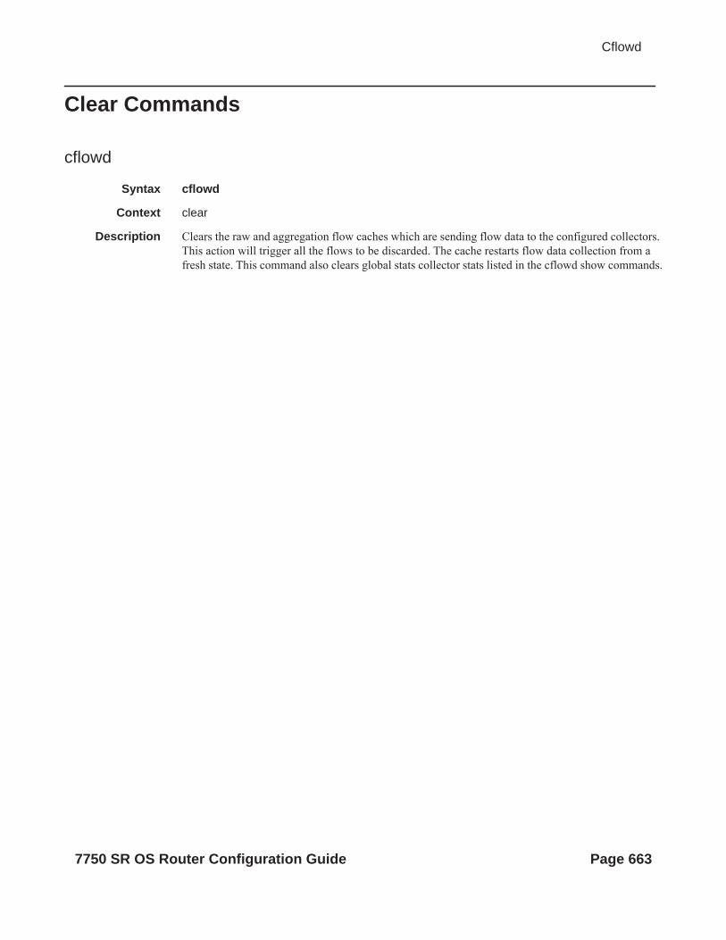
Cflowd
Clear Commands
cflowd
Syntax cflowd
Context clear
Description Clears the raw and aggregation flow caches which are sending flow data to the configured collectors. This action will trigger all the flows to be discarded. The cache restarts flow data collection from a fresh state. This command also clears global stats collector stats listed in the cflowd show commands.
7750 SR OS Router Configuration Guide Page 663

Page 664 7750 SR OS Router Configuration Guide
Common CLI Command Descriptions
In This ChapterThis section provides information about common Command Line Interface (CLI) syntax and command usage.
Topics in this chapter include:
• SAP syntax on page 666
7750 SR OS Router Configuration Guide Page 665

Common CLI Command Descriptions
Common Service CommandsSAP syntax
sap
Syntax [no] sap sap-id
Description This command specifies the physical port identifier portion of the SAP definition.
Parameters sap-id — Specifies the physical port identifier portion of the SAP definition.
The sap-id can be configured in one of the following formats:
Type Syntax Example
port-id slot/mda/port[.channel] 1/1/5
null [port-id | bundle-id| bpgrp-id | lag-id | aps-id] port-id: 1/1/3bundle-id: bundle-ppp-1/1.1bpgrp-id: bpgrp-ima-1lag-id: lag-63aps-id: aps-1
dot1q [port-id | bundle-id| bpgrp-id | lag-id | aps-id]:qtag1 port-id:qtag1: 1/1/3:100bundle-id: bundle-ppp-1/1.1bpgrp-id: bpgrp-ima-1lag-id:qtag1:lag-61:102aps-id:qtag1: aps-1:27
qinq [port-id | bundle-id| bpgrp-id | lag-id]:qtag1.qtag2 port-id:qtag1.qtag2: 1/1/3:100.10bundle-id: bundle-ppp-1/1.1bpgrp-id: bpgrp-ima-1lag-id:qtag1.qtag2:lag-10:
atm [port-id | aps-id | bundle-id | bpgrp-id][:vpi/vci |vpi |vpi1.vpi2] port-id: 1/1/1aps-id: aps-1bundle-id: bundle-ima-1/1.1
bundle-ppp-1/1.1bpgrp-id: bpgrp-ima-1vpi/vci: 16/26vpi: 16vpi1.vpi2: 16.200
frame-relay
[port-id | aps-id]:dlci port-id: 1/1/1:100 aps-id: aps-1dlci: 16
cisco-hdlc slot/mda/port.channel port-id: 1/1/3.1
Page 666 7750 SR OS Router Configuration Guide

Common CLI Command Descriptions
Values: sap-id null [port-id | bundle-id | bpgrp-id | lag-id | aps-id]dot1q [port-id | bundle-id | bpgrp-id | lag-id | aps-id]:qtag1qinq [port-id | bundle-id | bpgrp-id | lag-id]:qtag1.qtag2atm [port-id | aps-id][:vpi/vci|vpi| vpi1.vpi2]frame [port-id | aps-id]:dlcicisco-hdlc slot/mda/port.channelcem slot/mda/port.channelima-grp [bundle-id[:vpi/vci|vpi|vpi1.vpi2]port-id slot/mda/port[.channel]bundle-id bundle-type-slot/mda.bundle-num
bundle keywordtype ima, fr, pppbundle-num 1 — 336
bpgrp-id bpgrp-type-bpgrp-numbpgrp keywordtype ima, fr, pppbpgrp-num 1 — 2000
aps-id aps-group-id[.channel]aps keywordgroup-id 1 — 64
ccag-id ccag-id.path-id[cc-type]:cc-idccag keywordid 1 — 8path-id a, bcc-type .sap-net, .net-sapcc-id 0 — 4094
lag-id lag-idlag keywordid 1 — 200
qtag1 0 — 4094qtag2 *, 0 — 4094vpi NNI: 0 — 4095
UNI: 0 — 255 vci 1, 2, 5 — 65535dlci 16 — 1022ipsec-id ipsec-id.[private | public]:tag
ipsec keywordid 1 — 4tag 0 — 4094
bundle-id — Specifies the multilink bundle to be associated with this IP interface. The bundle keyword must be entered at the beginning of the parameter. The command syntax must be configured as follows:
bundle-id: bundle-type-slot-id/mda-slot.bundle-numbundle-id value range: 1 — 336
For example:
7750 SR OS Router Configuration Guide Page 667

Common CLI Command Descriptions
*A:ALA-12>config# port bundle-ppp-5/1.1*A:ALA-12>config>port# multilink-bundle
bgprp-id — Specifies the bundle protection group ID to be associated with this IP interface. The bpgrp keyword must be entered at the beginning of the parameter.
The command syntax must be configured as follows:
bpgrp-id: bpgrp-type-bpgrp-numtype: imabpgrp-num value range: 1 — 2000
For example:
*A:ALA-12>config# port bpgrp-ima-1*A:ALA-12>config>service>vpls$ sap bpgrp-ima-1
qtag1, qtag2 — Specifies the encapsulation value used to identify the SAP on the port or sub-port. If this parameter is not specificially defined, the default value is 0.
Values qtag1: * | 0 — 4094qtag2 : * | 0 — 4094
The values depends on the encapsulation type configured for the interface. The following table describes the allowed values for the port and encapsulation types.
Port Type Encap-Type Allowed Values Comments
Ethernet Null 0 The SAP is identified by the port.
Ethernet Dot1q 0 — 4094 The SAP is identified by the 802.1Q tag on the port. Note that a 0 qtag1 value also accepts untagged packets on the dot1q port.
Ethernet QinQ qtag1: 0 — 4094qtag2: 0 — 4094
The SAP is identified by two 802.1Q tags on the port. Note that a 0 qtag1 value also accepts untagged packets on the Dot1q port.
SONET/SDH IPCP - The SAP is identified by the channel. No BCP is deployed and all traffic is IP.
SONET/SDHTDM
BCP-Null 0 The SAP is identified with a single service on the channel. Tags are assumed to be part of the customer packet and not a service delimiter.
SONET/SDHTDM
BCP-Dot1q 0 — 4094 The SAP is identified by the 802.1Q tag on the channel.
SONET/SDHTDM
Frame Relay 16 — 991 The SAP is identified by the data link connection identifier (DLCI).
SONET/SDHATM
ATM vpi (NNI) 0 — 4095 vpi (UNI) 0 — 255vci 1, 2, 5 — 65535
The SAP is identified by port or by PVPC or PVCC identifier (vpi, vpi/vci, or vpi range)
Page 668 7750 SR OS Router Configuration Guide

Common CLI Command Descriptions
sap ipsec-id.private|public:tag — This parameter associates an IPSec group SAP with this interface. This is the public side for an IPSec tunnel. Tunnels referencing this IPSec group in the private side may be created if their local IP is in the subnet of the interface subnet and the routing context specified matches with the one of the interface.
This context will provide a SAP to the tunnel. The operator may associate an ingress and egress QoS policies as well as filters and virtual scheduling contexts. Internally this creates an Ethernet SAP that will be used to send and receive encrypted traffic to and from the MDA. Multiple tunnels can be associated with this SAP. The “tag” will be a dot1q value. The operator may see it as an identifier. The range is limited to 1 — 4095.
7750 SR OS Router Configuration Guide Page 669

Common CLI Command Descriptions
Page 670 7750 SR OS Router Configuration Guide

Standards and Protocol SupportNote that this Standards Compliance list is subject to change.
Ethernet StandardsIEEE 802.1ab-REV/D3 Station and
Media Access Control Connectivity Discovery
IEEE 802.1d BridgingIEEE 802.1p/Q VLAN TaggingIEEE 802.1s Multiple Spanning TreeIEEE 802.1w Rapid Spanning Tree
ProtocolIEEE 802.1x Port Based Network Access
ControlIEEE 802.1ad Provider BridgesIEEE 802.1ah Provider Backbone
BridgesIEEE 802.1ag Service Layer OAMIEEE 802.3ah Ethernet in the First MileIEEE 802.1ak Multiple MAC
Registration ProtocolIEEE 802.3 10BaseTIEEE 802.3ad Link AggregationIEEE 802.3ae 10Gbps EthernetIEEE 802.3ah Ethernet OAMIEEE 802.3u 100BaseTXIEEE 802.3x Flow ControlIEEE 802.3z 1000BaseSX/LXITU-T Y.1731 OAM functions and
mechanisms for Ethernet based networks
ITU-T G.8031 Ethernet linear protection switching
ITU-T G.8032 Ethernet Ring Protection Switching (version 2)
OSPFRFC 1765 OSPF Database OverflowRFC 2328 OSPF Version 2RFC 2370 Opaque LSA Support RFC 2740 OSPF for IPv6 (OSPFv3) RFC 3101 OSPF NSSA OptionRFC 3137 OSPF Stub Router
AdvertisementRFC 3623 Graceful OSPF Restart – GR
helperRFC 3630 Traffic Engineering (TE)
Extensions to OSPF Version 2
RFC 4203 OSPF Extensions in Support of Generalized Multi-Protocol Label Switching (GMPLS) - (support of Link Local/Remote Identifiers and SRLG sub-TLVs)
RFC 5185 OSPF Multi-Area AdjacencyRFC5243 OSPF Database Summary List
Optimization
BGPRFC 1397 BGP Default Route
AdvertisementRFC 1772 Application of BGP in the
InternetRFC 1965 Confederations for BGP RFC 1997 BGP Communities AttributeRFC 2385 Protection of BGP Sessions
via MD5RFC 2439 BGP Route Flap DampeningRFC 2558 Multiprotocol Extensions for
BGP-4RFC 2918 Route Refresh Capability for
BGP-4RFC 3107 Carrying Label Information in
BGP-4RFC 3392 Capabilities Advertisement
with BGP4RFC 4271 BGP-4 (previously RFC 1771)RFC 4360 BGP Extended Communities
AttributeRFC 4364 BGP/MPLS IP Virtual Private
Networks (VPNs) (previously RFC 2547bis BGP/MPLS VPNs)
RFC 4456 BGP Route Reflection: Alternative to Full-mesh IBGP
RFC 4486 Subcodes for BGP Cease Notification Message
RFC 4577 OSPF as the Provider/Customer Edge Protocol for BGP/MPLS IP Virtual Private Networks (VPNs)
RFC 4659 BGP-MPLS IP Virtual Private Network (VPN) Extension for IPv6 VPN
RFC 4684 Constrained Route Distribution for Border Gateway Protocol/MultiProtocol Label
Switching (BGP/MPLS) Internet Protocol (IP) Virtual Private Networks (VPNs)
RFC 4724 Graceful Restart Mechanism for BGP – GR helper
RFC 4760 Multi-protocol Extensions for BGP
RFC 4798 Connecting IPv6 Islands over IPv4 MPLS Using IPv6 Provider Edge Routers (6PE)
RFC 4893 BGP Support for Four-octet AS Number Space
RFC 5004 Avoid BGP Best Path Transitions from One External to Another
RFC 5065 Confederations for BGP (obsoletes 3065)
RFC 5291 Outbound Route Filtering Capability for BGP-4
RFC 5575 Dissemination of Flow Specification Rules
RFC 5668 4-Octet AS Specific BGP Extended Community
draft-ietf-idr-add-paths Advertisement of Multiple Paths in BGP Advertisement of the Best External Route in BGP
draft-ietf-idr-best-external
IS-ISISO/IEC 10589:2002, Second Edition
Intermediate System to Intermediate System Intra-Domain Routeing Information Exchange Protocol
RFC 1195 Use of OSI IS-IS for Routing in TCP/IP and Dual Environments
RFC 2973 IS-IS Mesh GroupsRFC 3359 Reserved Type, Length and
Value (TLV) Codepoints in Intermediate System to Intermediate System
RFC 3719 Recommendations for Interoperable Networks using Intermediate System to Intermediate System (IS-IS)
RFC 3787 Recommendations for Interoperable IP Networks using
Standards and Protocols Page 671

Standards and Protocols
Intermediate System to Intermediate System (IS-IS)
RFC 4971 Intermediate System to Intermediate System (IS-IS) Extensions for Advertising Router Information
RFC 5120 M-ISIS: Multi Topology (MT) Routing in IS-IS
RFC 5301 Dynamic Hostname Exchange Mechanism for IS-IS
RFC 5302 Domain-wide Prefix Distribution with Two-Level IS-IS
RFC 5303 Three-Way Handshake for IS-IS Point-to-Point Adjacencies
RFC 5304 IS-IS Cryptographic Authentication
RFC 5305 IS-IS Extensions for Traffic Engineering TE
RFC 5306 Restart Signaling for IS-ISRFC 5307 IS-IS Extensions in Support of
Generalized Multi-Protocol Label Switching (GMPLS)
RFC 5309 Point-to-Point Operation over LAN in Link State Routing Protocols
RFC 5310 IS-IS Generic Cryptographic Authentication
RFC 6213 IS-IS BFD-Enabled TLVRFC 6329 IS-IS Extensions Supporting
IEEE 802.1aq Shortest Path Bridging
draft-ietf-isis-mi-02 IS-IS Multi-Instance
IPSecRFC 2401 Security Architecture for the
Internet ProtocolRFC 2406 IP Encapsulating Security
Payload (ESP)RFC 2409 The Internet Key Exchange
(IKE)RFC 2560 X.509 Internet Public Key
Infrastructure Online Certificate Status
Protocol - OCSPRFC 3706 IKE Dead Peer DetectionRFC 3947 Negotiation of NAT-Traversal
in the IKERFC 3948 UDP Encapsulation of IPsec
ESP PacketsRFC 4210 Internet X.509 Public Key
Infrastructure Certificate Management
Protocol (CMP)
RFC 4211 Internet X.509 Public Key Infrastructure
Certificate Request Message Format (CRMF)
RFC 5996 Internet Key Exchange Protocol Version 2 (IKEv2)
RFC 5998 An Extension for EAP-Only Authentication in IKEv2
draft-ietf-ipsec-isakmp-xauth-06 – Extended Authentication within ISAKMP/Oakley (XAUTH)
draft-ietf-ipsec-isakmp-modecfg-05 – The ISAKMP Configuration Method
IPv6RFC 1981 Path MTU Discovery for IPv6RFC 2375 IPv6 Multicast Address
AssignmentsRFC 2460 Internet Protocol, Version 6
(IPv6) SpecificationRFC 2461 Neighbor Discovery for IPv6RFC 2462 IPv6 Stateless Address Auto
configurationRFC 2464 Transmission of IPv6 Packets
over Ethernet NetworksRFC 2529 Transmission of IPv6 over
IPv4 Domains without Explicit Tunnels
RFC 2545 Use of BGP-4 Multiprotocol Extension for IPv6 Inter-Domain Routing
RFC 2710 Multicast Listener Discovery (MLD) for IPv6
RFC 2740 OSPF for IPv6RFC 3306 Unicast-Prefix-based IPv6
Multicast AddressesRFC 3315 Dynamic Host Configuration
Protocol for IPv6RFC 3587 IPv6 Global Unicast Address
FormatRFC3590 Source Address Selection for
the Multicast Listener Discovery (MLD) Protocol
RFC 3810 Multicast Listener Discovery Version 2 (MLDv2) for IPv6
RFC 4007 IPv6 Scoped Address Architecture
RFC 4193 Unique Local IPv6 Unicast Addresses
RFC 4291 IPv6 Addressing ArchitectureRFC 4443 Internet Control Message
Protocol (ICMPv6) for the Internet
Protocol Version 6 (IPv6) Specification
RFC 4552 Authentication/Confidentiality for OSPFv3
RFC 4659 BGP-MPLS IP Virtual Private Network (VPN) Extension for IPv6 VPN
RFC 5072 IP Version 6 over PPPRFC 5095 Deprecation of Type 0 Routing
Headers in IPv6draft-ietf-isis-ipv6-05draft-ietf-isis-wg-multi-topology-xx.txt
MulticastRFC 1112 Host Extensions for IP
Multicasting (Snooping)RFC 2236 Internet Group Management
Protocol, (Snooping)RFC 3376 Internet Group Management
Protocol, Version 3 (Snooping)RFC 2362 Protocol Independent
Multicast-Sparse Mode (PIMSM)RFC 3618 Multicast Source Discovery
Protocol (MSDP)RFC 3446 Anycast Rendevous Point
(RP) mechanism using Protocol Independent Multicast (PIM) and Multicast Source Discovery Protocol (MSDP)
RFC 4601 Protocol Independent Multicast - Sparse Mode (PIM-SM): Protocol Specification (Revised)
RFC 4604 Using IGMPv3 and MLDv2 for Source-Specific Multicast
RFC 4607 Source-Specific Multicast for IP
RFC 4608 Source-Specific Protocol Independent Multicast in 232/8
RFC 4610 Anycast-RP Using Protocol Independent Multicast (PIM)
draft-ietf-pim-sm-bsr-06. Bootstrap Router (BSR) Mechanism for PIM
draft-rosen-vpn-mcast-15.txt Multicast in MPLS/BGP IP VPNs
draft-ietf-l3vpn-2547bis-mcast-07: Multicast in MPLS/BGP IP VPNs
draft-ietf-l3vpn-2547bis-mcast-bgp-05: BGP Encodings and Procedures for Multicast in MPLS/BGP IP VPNs
RFC 3956: Embedding the Rendezvous Point (RP) Address in an IPv6 Multicast Address
Page 672 Standards and Protocols
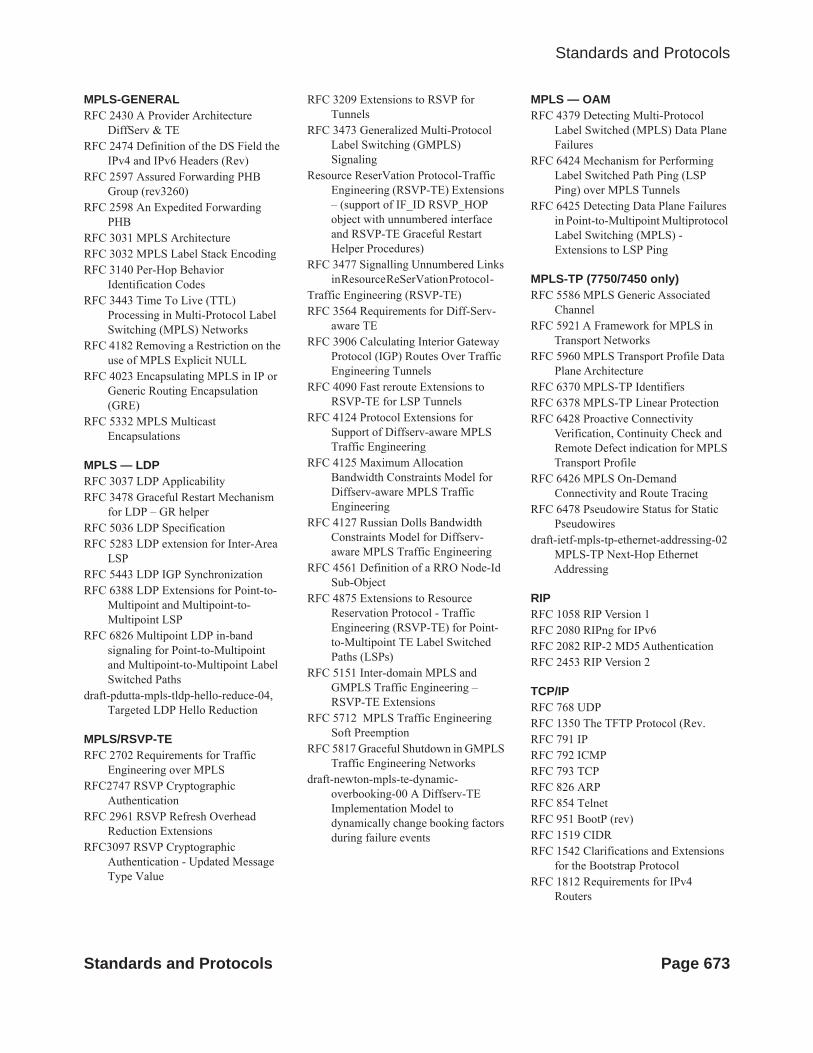
Standards and Protocols
MPLS-GENERAL RFC 2430 A Provider Architecture
DiffServ & TERFC 2474 Definition of the DS Field the
IPv4 and IPv6 Headers (Rev)RFC 2597 Assured Forwarding PHB
Group (rev3260)RFC 2598 An Expedited Forwarding
PHBRFC 3031 MPLS ArchitectureRFC 3032 MPLS Label Stack EncodingRFC 3140 Per-Hop Behavior
Identification CodesRFC 3443 Time To Live (TTL)
Processing in Multi-Protocol Label Switching (MPLS) Networks
RFC 4182 Removing a Restriction on the use of MPLS Explicit NULL
RFC 4023 Encapsulating MPLS in IP or Generic Routing Encapsulation (GRE)
RFC 5332 MPLS Multicast Encapsulations
MPLS — LDPRFC 3037 LDP ApplicabilityRFC 3478 Graceful Restart Mechanism
for LDP – GR helperRFC 5036 LDP SpecificationRFC 5283 LDP extension for Inter-Area
LSPRFC 5443 LDP IGP SynchronizationRFC 6388 LDP Extensions for Point-to-
Multipoint and Multipoint-to-Multipoint LSP
RFC 6826 Multipoint LDP in-band signaling for Point-to-Multipoint and Multipoint-to-Multipoint Label Switched Paths
draft-pdutta-mpls-tldp-hello-reduce-04, Targeted LDP Hello Reduction
MPLS/RSVP-TERFC 2702 Requirements for Traffic
Engineering over MPLSRFC2747 RSVP Cryptographic
AuthenticationRFC 2961 RSVP Refresh Overhead
Reduction ExtensionsRFC3097 RSVP Cryptographic
Authentication - Updated Message Type Value
RFC 3209 Extensions to RSVP for Tunnels
RFC 3473 Generalized Multi-Protocol Label Switching (GMPLS) Signaling
Resource ReserVation Protocol-Traffic Engineering (RSVP-TE) Extensions – (support of IF_ID RSVP_HOP object with unnumbered interface and RSVP-TE Graceful Restart Helper Procedures)
RFC 3477 Signalling Unnumbered Links in Resource ReSerVation Protocol -
Traffic Engineering (RSVP-TE)RFC 3564 Requirements for Diff-Serv-
aware TERFC 3906 Calculating Interior Gateway
Protocol (IGP) Routes Over Traffic Engineering Tunnels
RFC 4090 Fast reroute Extensions to RSVP-TE for LSP Tunnels
RFC 4124 Protocol Extensions for Support of Diffserv-aware MPLS Traffic Engineering
RFC 4125 Maximum Allocation Bandwidth Constraints Model for Diffserv-aware MPLS Traffic Engineering
RFC 4127 Russian Dolls Bandwidth Constraints Model for Diffserv-aware MPLS Traffic Engineering
RFC 4561 Definition of a RRO Node-Id Sub-Object
RFC 4875 Extensions to Resource Reservation Protocol - Traffic Engineering (RSVP-TE) for Point-to-Multipoint TE Label Switched Paths (LSPs)
RFC 5151 Inter-domain MPLS and GMPLS Traffic Engineering – RSVP-TE Extensions
RFC 5712 MPLS Traffic Engineering Soft Preemption
RFC 5817 Graceful Shutdown in GMPLS Traffic Engineering Networks
draft-newton-mpls-te-dynamic-overbooking-00 A Diffserv-TE Implementation Model to dynamically change booking factors during failure events
MPLS — OAMRFC 4379 Detecting Multi-Protocol
Label Switched (MPLS) Data Plane Failures
RFC 6424 Mechanism for Performing Label Switched Path Ping (LSP Ping) over MPLS Tunnels
RFC 6425 Detecting Data Plane Failures in Point-to-Multipoint Multiprotocol Label Switching (MPLS) - Extensions to LSP Ping
MPLS-TP (7750/7450 only)RFC 5586 MPLS Generic Associated
ChannelRFC 5921 A Framework for MPLS in
Transport NetworksRFC 5960 MPLS Transport Profile Data
Plane ArchitectureRFC 6370 MPLS-TP IdentifiersRFC 6378 MPLS-TP Linear ProtectionRFC 6428 Proactive Connectivity
Verification, Continuity Check and Remote Defect indication for MPLS Transport Profile
RFC 6426 MPLS On-Demand Connectivity and Route Tracing
RFC 6478 Pseudowire Status for Static Pseudowires
draft-ietf-mpls-tp-ethernet-addressing-02 MPLS-TP Next-Hop Ethernet Addressing
RIPRFC 1058 RIP Version 1RFC 2080 RIPng for IPv6RFC 2082 RIP-2 MD5 AuthenticationRFC 2453 RIP Version 2
TCP/IPRFC 768 UDPRFC 1350 The TFTP Protocol (Rev.RFC 791 IPRFC 792 ICMPRFC 793 TCPRFC 826 ARPRFC 854 TelnetRFC 951 BootP (rev)RFC 1519 CIDRRFC 1542 Clarifications and Extensions
for the Bootstrap ProtocolRFC 1812 Requirements for IPv4
Routers
Standards and Protocols Page 673

Standards and Protocols
RFC 2347 TFTP option ExtensionRFC 2328 TFTP Blocksize OptionRFC 2349 TFTP Timeout Interval and
Transfer Size optionRFC 2401 Security Architecture for
Internet ProtocolRFC 2428 FTP Extensions for IPv6 and
NATsRFC 3596 DNS Extensions to Support IP
version 6RFC 5880 Bidirectional Forwarding
DetectionRFC 5881 BFD IPv4 and IPv6 (Single
Hop)RFC 5883 BFD for Multihop PathsRFC 5286 Basic Specification for IP Fast
Reroute: Loop-Free Alternatesdraft-litkowski-rtgwg-lfa-manageability-
01 Operational management of Loop Free Alternates
VRRPRFC 2787 Definitions of Managed
Objects for the Virtual Router Redundancy Protocol
RFC 3768 Virtual Router Redundancy Protocol
draft-ietf-vrrp-unified-spec-02 Virtual Router Redundancy Protocol Version 3 for IPv4 and IPv6
PPPRFC 1332 PPP IPCPRFC 1377 PPP OSINLCPRFC 1638/2878PPP BCPRFC 1661 PPP (rev RFC2151)RFC 1662 PPP in HDLC-like FramingRFC 1877 PPP Internet Protocol Control
Protocol Extensions for Name Server Addresses
RFC 1989 PPP Link Quality MonitoringRFC 1990 The PPP Multilink Protocol
(MP)RFC 1994 PPP Challenge Handshake Authentication Protocol (CHAP)RFC 2516 A Method for Transmitting
PPP Over EthernetRFC 2615 PPP over SONET/SDHRFC 2686 The Multi-Class Extension to
Multi-Link PPP
Frame Relay FRF.1.2 - PVC User-to-Network
Interface (UNI) Implementation Agreement
FRF.5 - Frame Relay/ATM PVC Network Interworking Implementation
ANSI T1.617 Annex D, DSS1 — Signalling Specification For Frame Relay Bearer Service.
FRF2.2. PVC Network-to- Network Interface (NNI) Implementation Agreement.
FRF.12 Frame Relay Fragmentation Implementation Agreement
FRF.16.1 Multilink Frame Relay UNI/NNI Implementation Agreement
ITU-T Q.933 Annex A Additional procedures for Permanent Virtual Connection (PVC) status management
ATMRFC 1626 Default IP MTU for use over
ATM AAL5RFC 2514 Definitions of Textual
Conventions and OBJECT_IDENTITIES for ATM Management
RFC 2515 Definition of Managed Objects for ATM Management RFC 2684 Multiprotocol Encapsulation over ATM Adaptation Layer 5
AF-TM-0121.000 Traffic Management Specification Version 4.1
ITU-T Recommendation I.610 B-ISDN Operation and Maintenance Principles and Functions version 11/95
ITU-T Recommendation I.432.1 BISDN user-network interface – Physical layer specification: General characteristics
GR-1248-CORE Generic Requirements for Operations of ATM Network Elements (NEs). Issue 3
GR-1113-CORE Bellcore, Asynchronous Transfer Mode (ATM) and ATM Adaptation Layer (AAL) Protocols Generic Requirements, Issue 1
AF-ILMI-0065.000 Integrated Local Management Interface (ILMI) Version 4.0
AF-TM-0150.00 Addendum to Traffic Management v4.1 optional
minimum desired cell rate indication for UBR
AF-PHY-0086.001 Inverse Multiplexing for ATM (IMA) Specification Version 1.1
DHCPRFC 2131 Dynamic Host Configuration
Protocol (REV)RFC 3046 DHCP Relay Agent
Information Option (Option 82)RFC 1534 Interoperation between DHCP
and BOOTP
Policy Management and Credit Control3GPP TS 29.212 Policy and Charging
Control (PCC) over Gx/Sd Reference Point (Release 11) - Gx support as it applies to wireline environment (BNG)
RFC 3588 Diameter Base ProtocolRFC 4006 Diameter Credit Control
Application
NATRFC 6333 Dual-Stack Lite Broadband
Deployments Following IPv4 Exhaustion
RFC 6334 Dynamic Host Configuration Protocol for IPv6 (DHCPv6) Option for Dual-Stack Lite
RFC 6888 Common Requirements For Carrier-Grade NATs (CGNs)
RFC 5508 NAT Behavioral Requirements for ICMP
RFC 5382 NAT Behavioral Requirements for TCP
RFC 6146 Statefull NAT64
VPLSRFC 4761 Virtual Private LAN Service
(VPLS) Using BGP for Auto-Discovery and Signaling
RFC 4762 Virtual Private LAN Services Using LDP
RFC 5501 Requirements for Multicast Support in Virtual Private LAN Services
RFC 6074 Provisioning, Auto-Discovery, and Signaling in Layer 2 Virtual Private Networks (L2VPNs)
draft-ietf-l2vpn-vpls-mcast-13. Multicast in VPLS
Page 674 Standards and Protocols
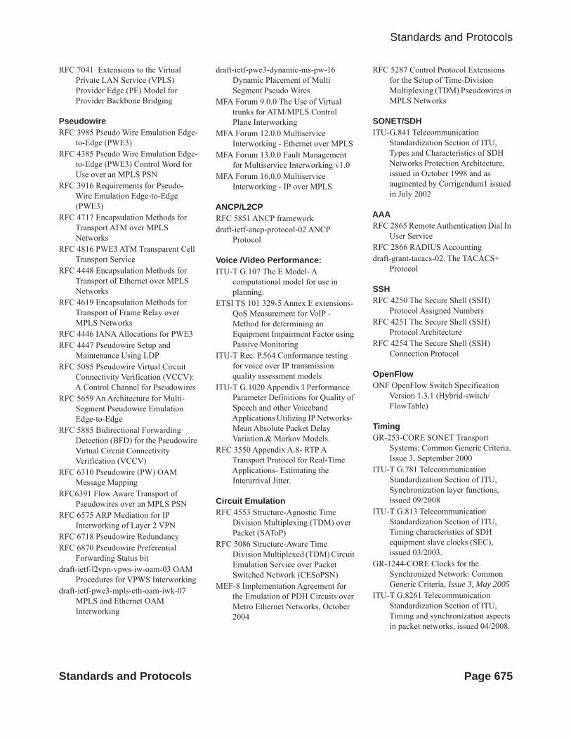
Standards and Protocols
RFC 7041 Extensions to the Virtual Private LAN Service (VPLS) Provider Edge (PE) Model for Provider Backbone Bridging
PseudowireRFC 3985 Pseudo Wire Emulation Edge-
to-Edge (PWE3)RFC 4385 Pseudo Wire Emulation Edge-
to-Edge (PWE3) Control Word for Use over an MPLS PSN
RFC 3916 Requirements for Pseudo- Wire Emulation Edge-to-Edge (PWE3)
RFC 4717 Encapsulation Methods for Transport ATM over MPLS Networks
RFC 4816 PWE3 ATM Transparent Cell Transport Service
RFC 4448 Encapsulation Methods for Transport of Ethernet over MPLS Networks
RFC 4619 Encapsulation Methods for Transport of Frame Relay over MPLS Networks
RFC 4446 IANA Allocations for PWE3RFC 4447 Pseudowire Setup and
Maintenance Using LDPRFC 5085 Pseudowire Virtual Circuit
Connectivity Verification (VCCV): A Control Channel for Pseudowires
RFC 5659 An Architecture for Multi-Segment Pseudowire Emulation Edge-to-Edge
RFC 5885 Bidirectional Forwarding Detection (BFD) for the Pseudowire Virtual Circuit Connectivity Verification (VCCV)
RFC 6310 Pseudowire (PW) OAM Message Mapping
RFC6391 Flow Aware Transport of Pseudowires over an MPLS PSN
RFC 6575 ARP Mediation for IP Interworking of Layer 2 VPN
RFC 6718 Pseudowire RedundancyRFC 6870 Pseudowire Preferential
Forwarding Status bitdraft-ietf-l2vpn-vpws-iw-oam-03 OAM
Procedures for VPWS Interworkingdraft-ietf-pwe3-mpls-eth-oam-iwk-07
MPLS and Ethernet OAM Interworking
draft-ietf-pwe3-dynamic-ms-pw-16 Dynamic Placement of Multi Segment Pseudo Wires
MFA Forum 9.0.0 The Use of Virtual trunks for ATM/MPLS Control Plane Interworking
MFA Forum 12.0.0 Multiservice Interworking - Ethernet over MPLS
MFA Forum 13.0.0 Fault Management for Multiservice Interworking v1.0
MFA Forum 16.0.0 Multiservice Interworking - IP over MPLS
ANCP/L2CPRFC 5851 ANCP framework draft-ietf-ancp-protocol-02 ANCP
Protocol
Voice /Video Performance:ITU-T G.107 The E Model- A
computational model for use in planning.
ETSI TS 101 329-5 Annex E extensions- QoS Measurement for VoIP -Method for determining an Equipment Impairment Factor using Passive Monitoring
ITU-T Rec. P.564 Conformance testing for voice over IP transmission quality assessment models
ITU-T G.1020 Appendix I Performance Parameter Definitions for Quality of Speech and other Voiceband Applications Utilizing IP Networks- Mean Absolute Packet Delay Variation.& Markov Models.
RFC 3550 Appendix A.8- RTP A Transport Protocol for Real-Time Applications- Estimating the Interarrival Jitter.
Circuit EmulationRFC 4553 Structure-Agnostic Time
Division Multiplexing (TDM) over Packet (SAToP)
RFC 5086 Structure-Aware Time Division Multiplexed (TDM) Circuit Emulation Service over Packet Switched Network (CESoPSN)
MEF-8 Implementation Agreement for the Emulation of PDH Circuits over Metro Ethernet Networks, October 2004
RFC 5287 Control Protocol Extensions for the Setup of Time-Division Multiplexing (TDM) Pseudowires in MPLS Networks
SONET/SDHITU-G.841 Telecommunication
Standardization Section of ITU, Types and Characteristics of SDH Networks Protection Architecture, issued in October 1998 and as augmented by Corrigendum1 issued in July 2002
AAARFC 2865 Remote Authentication Dial In
User ServiceRFC 2866 RADIUS Accountingdraft-grant-tacacs-02. The TACACS+
Protocol
SSHRFC 4250 The Secure Shell (SSH)
Protocol Assigned NumbersRFC 4251 The Secure Shell (SSH)
Protocol Architecture RFC 4254 The Secure Shell (SSH)
Connection Protocol
OpenFlowONF OpenFlow Switch Specification
Version 1.3.1 (Hybrid-switch/FlowTable)
TimingGR-253-CORE SONET Transport
Systems: Common Generic Criteria. Issue 3, September 2000
ITU-T G.781 Telecommunication Standardization Section of ITU, Synchronization layer functions, issued 09/2008
ITU-T G.813 Telecommunication Standardization Section of ITU, Timing characteristics of SDH equipment slave clocks (SEC), issued 03/2003.
GR-1244-CORE Clocks for the Synchronized Network: Common Generic Criteria, Issue 3, May 2005
ITU-T G.8261 Telecommunication Standardization Section of ITU, Timing and synchronization aspects in packet networks, issued 04/2008.
Standards and Protocols Page 675

Standards and Protocols
ITU-T G.8262 Telecommunication Standardization Section of ITU, Timing characteristics of synchronous Ethernet equipment slave clock (EEC), issued 08/2007.
ITU-T G.8264 Telecommunication Standardization Section of ITU, Distribution of timing information through packet networks, issued 10/2008.
ITU-T G.8265.1 Telecommunication Standardization Section of ITU, Precision time protocol telecom profile for frequency synchronization, issued 10/2010.
IEEE 1588-2008 IEEE Standard for a Precision Clock Synchronization Protocol for Networked Measurement and Control Systems
Network ManagementITU-T X.721 Information technology-
OSI-Structure of Management Information
ITU-T X.734 Information technology-OSI-Systems Management: Event Report Management Function
M.3100/3120 Equipment and Connection Models
TMF 509/613 Network Connectivity Model
RFC 1157 SNMPv1RFC 1215 A Convention for Defining
Traps for use with the SNMPRFC 1657 BGP4-MIBRFC 1724 RIPv2-MIBRFC 1850 OSPF-MIBRFC 1907 SNMPv2-MIBRFC 2011 IP-MIBRFC 2138 RADIUSRFC 2206 RSVP-MIBRFC 2452 IPv6 Management Information
Base for theTransmission Control ProtocolRFC 2465 Management Information
Base for IPv6: Textual Conventions and General Group
RFC 2558 SONET-MIBRFC 2571 SNMP-FRAMEWORKMIBRFC 2572 SNMP-MPD-MIBRFC 2573 SNMP-TARGET-&-NOTIFICATION-MIB
RFC 2574 SNMP-USER-BASED-SMMIB
RFC 2575 SNMP-VIEW-BASEDACM-MIB
RFC 2576 SNMP-COMMUNITY-MIBRFC 2578 Structure of Management
Information Version 2 (SMIv2)RFC 2665 EtherLike-MIBRFC 2819 RMON-MIBRFC 2863 IF-MIBRFC 2864 INVERTED-STACK-MIBRFC 2987 VRRP-MIBRFC 3014 NOTIFICATION-LOGMIBRFC 3019 IP Version 6 Management
Information Base for The Multicast Listener Discovery Protocol
RFC 3164 SyslogRFC 3273 HCRMON-MIBRFC 3411 An Architecture for
Describing Simple Network Management Protocol (SNMP) Management Frameworks
RFC 3412 Message Processing and Dispatching for the Simple Network Management Protocol (SNMP)
RFC 3413 Simple Network Management Protocol (SNMP) Applications
RFC 3414 User-based Security Model (USM) for version 3 of the Simple Network Management Protocol (SNMPv3)
RFC 3418 SNMP MIBRFC 3826 The Advanced Encryption
Standard (AES) Cipher Algorithm in the SNMP User-based Security Model
RFC 4113 Management Information Base for the User Datagram Protocol (UDP)
RFC 4292 IP-FORWARD-MIBRFC 4293 MIB for the Internet ProtocolRFC 5101 Specification of the IP Flow
Information Export (IPFIX) Protocol for the Exchange of IP Traffic Flow Information
RFC 6242 Using the NETCONF Protocol over Secure Shell (SSH)
draft-ietf-bfd-mib-00 Bidirectional Forwarding Detection Management Information Base
draft-ietf-isis-wg-mib-06 Management Information Base for Intermediate
System to Intermediate System (IS-IS)
draft-ietf-ospf-mib-update-04 OSPF Version 2 Management Information Base
draft-ietf-mboned-msdp-mib-01 Multicast Source Discovery protocol MIB
draft-ietf-mpls-lsr-mib-06 Multiprotocol Label Switching (MPLS) Label Switching Router (LSR) Management Information Base
draft-ietf-mpls-te-mib-04 Multiprotocol Label Switching (MPLS) Traffic Engineering Management Information Base
draft-ietf-mpls-ldp-mib-07 MPLS Label Switch Router Management Information Base Using SMIv2
IANA ifType MIBIEEE 802.3- LAG-MIB
Page 676 Standards and Protocols