7702041-mu-41 (4)-e (en) tyc - atersa.com · * nota: use m6 din 9021 washer for hook v4 profile....
TRANSCRIPT
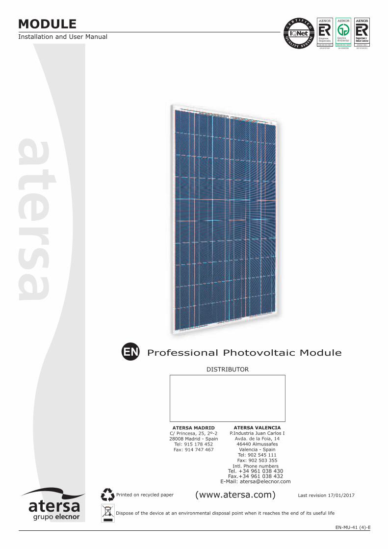
Professional Photovoltaic ModuleEN
DISTRIBUTOR
Intl. Phone numbersTel. +34 961 038 430Fax.+34 961 038 432
E-Mail: [email protected]
ATERSA MADRID
C/ Princesa, 25, 2º-2
el: 915 178 452Fax: 914 747 467
28008 Madrid - SpainT
ATERSA VALENCIA
P.Industria Juan Carlos I
46440 AlmussafesValencia - SpainTel: 902 545 111Fax: 902 503 355
Avda. de la Foia, 14
MODULEInstallation and User Manual
(www.atersa.com) Last revision 17/01/2017Printed on recycled paper
UNE-EN ISO 14001UNE-EN ISO 9001
ER-0979/1997 GA-2009/0396
OHSAS 18001
SST-0134/2012
Dispose of the device at an environmental disposal point when it reaches the end of its useful life
EN-MU-41 (4)-E
First, ATERSA and his team thank are grateful for your confidence by purchasingour products for your photovoltaic installation. This manual contains importantinformation about handling, installation and maintenance. Please carefully read andunderstand this manual before any handling. ATERSA not liable for damages causeddue to improper handling, installation or maintenance.
1.-GENERAL SAFETY 1
2.- TRANSPORT AND HANDLING 1
3.- WARNINGS 2
4.- POSITIONING AND INCLINATION 2
5.- INSTALLATION 3
7
8
6.- MAINTENANCE 8
7.- TECHNICAL SPECIFICATIONS 8
8.- GUARANTEE AND CERTIFICATES 8
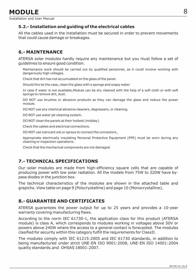
5.2.2.- Ground Connection
5.3.- Installation and Guiding of Electrical Cables
INDEX
3
3
4
5
5
5
5.1.- Mechanical Installation
5.2.- Electrical Installation
5.1.1.- Directly on the Structure
5.1.2.- Hook Fixing System
5.1.3.-Guide Insertion
5.2.1.- Electrical Connection of the Juntion Box
MODULEInstallation and User Manual
EN-MU-41 (4)-E
1.-GENERAL SAFETY
2.- TRANSPORT AND HANDLING
.
If not otherwise specified, it is recommended that requirements of the latest national or internationalelectrical standards be used.
isable to cover themodules with an opaque material. Do not touch the terminals with both hands and always useinsulated tools on the electrical connections.
Only allow access to the facility by qualified personnel.
Reversing the polarity of the cables destroys the bypass diodes of the junction box.
In normal conditions, the module can produce more current or voltage than the indicated for standardmeasurement conditions. So that, when dimensioning the system (cables section, fuses,…) the Iscand Voc values should be multiplied by 1,25.
Keep children and animals away from PV modules.
Install the modules in a strong structure and that this maintains the fire safety class.
Avoid uneven shade on the PV module surface. Shaded cells may become hot (“hot spot”phenomenon) which may result in permanent damage to the module.
Follow all safety precautions of other system components used.
Use module for its intended function only.
Store modules in a dry and ventilated room.
Do NOT place modules on an uneven surface
Do NOT place excessive loads on the module or twist the module frame, it may cause severe micro-cracks at the cell level
Do NOT stand, step, walk and/or jump on the module.
Do NOT drop module or allow objects to fall on module.
Do NOT mark the modules with sharp instrument. Avoid the contact of module back sheet with sharpobjects, as scratches may directly affect product safety
Do not use the junction box to hold or transport the module.
Broken or damaged modules must be handled carefully and with appropriate protectiveequipment.(Broken glass can be sharp and can cause injury if it is not handled int he right way .
When carrying a bigger module, two or more people should carry it by its frame and wear non-slipgloves (to avoid injury by a slipping module, cuts by the edge of a frame etc.
Module placement unsafely before installation can cause breakage, excessive deformation ... thataffect the reliability of the module.
Modules must NOT be manipulated from the central part of the long sides of the frame.´
x
x
x
x
x
x
x
x
x
x
x
x
x
x
x
x
x
x
x
x
x
The modules must be handled carefully during transport, storage and unpacking.
The safety instructions contained in this manual must be strictly followed in order toguarantee the safety of the user and the integrity of the module.
x
x
Ensure that the installation instructions provided in this document are followed. Guarantees or claimswill not be valid if the described process has not been followed
The cable pathway must provide mechanical support for the conductors and must provide sufficientprotection, in accordance with the Low Voltage Electrotechnical Regulations (REBT).
It must be handled by qualified personnel only. When exposed to the light, the modules generateelectricity. If several modules are connected in series, dangerously high voltages may be generated.To reduce potential electrical hazards during the installation process, it is adv
1MODULEInstallation and User Manual
EN-MU-41 (4)-E
2
3.-
4.-POSITIONING AND INCLINATION
x
x
x
x
x
x
x
x
x
x
x
x
NO debe intentar reparase ni emplearse ningún modulo roto, ya que el contacto con alguna parte deeste puede provocar en una electrocución.
NO exponer directamente la parte trasera a la luz solar.
Work ONLY under dry conditions, with dry modules and Insulated tools.
Do NOT install the module where flammable gases or vapors are present.
Do NOT drill holes in the frame or glass of the module.
Do NOT treat back sheet and front surface of the module with paint and adhesives.
Do NOT artificially concentrate light on the module.
Do NOT wear metallic jewelry while installing or trouble shooting the module.
Do NOTdisassemble, modify or adapt the module or remove any part of the module.
Be sure to completely ground all modules.
Do not touch terminals while module is exposed to light or during installation.
The connectors must be protected from dust, sund, wather,..., If the connectors are to remaindisconnected in the field.
The modules may be installed on plots of land, terraces, roofs and patios. ATERSAprovides a series of accessories for installations on façades, windows, balconies, wallsand cornices.
In order to ensure optimum performance the modules must not be placed in the shadowof other objects (plants, snow, buildings, construction elements, other modules, etc.),at least during the main hours of daylight.
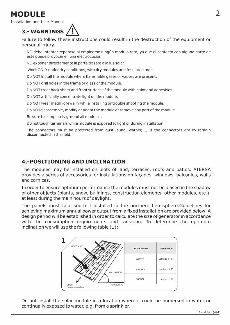
The panels must face south if installed in the northern hemisphere.Guidelines forachieving maximum annual power output from a fixed installation are provided below. Adesign period will be established in order to calculate the size of generator in accordancewith the consumption requirements and radiation. To determine the optimuminclination we will use the following table (1):
Do not install the solar module in a location where it could be immersed in water orcontinually exposed to water, e.g. from a sprinkler.
WARNINGS
Failure to follow these instructions could result in the destruction of the equipment orpersonal injury.
HORIZONTAL
INCLINATION
SOLAR LIGHT
SOUTH(North hemisphere)
INCLINATION
WINTER
DESIGN PERIOD
SUMMER
ANNUAL
Latitude +10º
Latitude -20º
Latitude -10º
1
MODULEInstallation and User Manual
EN-MU-41 (4)-E
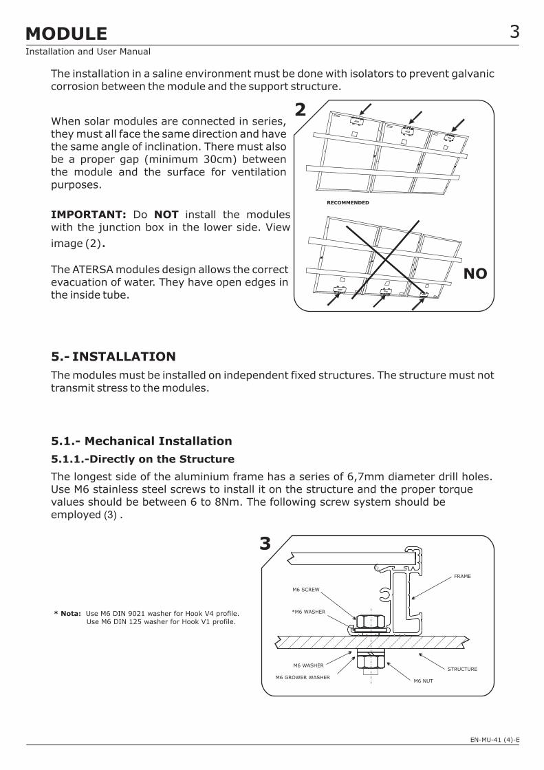
The installation in a saline environment must be done with isolators to prevent galvaniccorrosion between the module and the support structure.
When solar modules are connected in series,they must all face the same direction and havethe same angle of inclination. There must alsobe a proper gap (minimum 30cm) betweenthe module and the surface for ventilationpurposes.
(2)
The ATERSA modules design allows the correctevacuation of water. They have open edges inthe inside tube.
The modules must be installed on independent fixed structures. The structure must nottransmit stress to the modules.
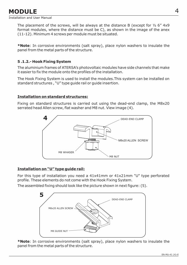
The longest side of the aluminium frame has a series of 6,7mm diameter drill holes.Use M6 stainless steel screws to install it on the structure and the proper torquevalues should be between 6 to 8Nm. The following screw system should beemploye .
.
5.- INSTALLATION
5.1.- Mechanical Installation
5.1.1.-Directly on the Structure
d (3)
IMPORTANT: NOTDo install the moduleswith the junction box in the lower side. View
image
RECOMMENDED
2
NO
* Nota: Use M6 DIN 9021 washer for Hook V4 profile.Use M6 DIN 125 washer for Hook V1 profile.
M6 WASHER
M6 GROWER WASHER
M6 SCREW
3
FRAME
M6 NUT
STRUCTURE
*M6 WASHER
3
‘
MODULEInstallation and User Manual
EN-MU-41 (4)-E
The placement of the screws, will be always at the distance B (except for ½ 6” 4x9format modules, where the distance must be C), as shown in the image of the anex(11-12). Minimum 4 screws per module must be situated.
(5).
5 .1.2.-
:
*Note
*Note
: In corrosive environments (salt spray), place nylon washers to insulate thepanel from the metal parts of the structure.
The aluminium frames of ATERSA’s photovoltaic modules have side channels that makeit easier to fix the module onto the profiles of the installation.
The Hook Fixing System is used to install the modules.This system can be installed onstandard structures , “U” type guide rail or guide insertion.
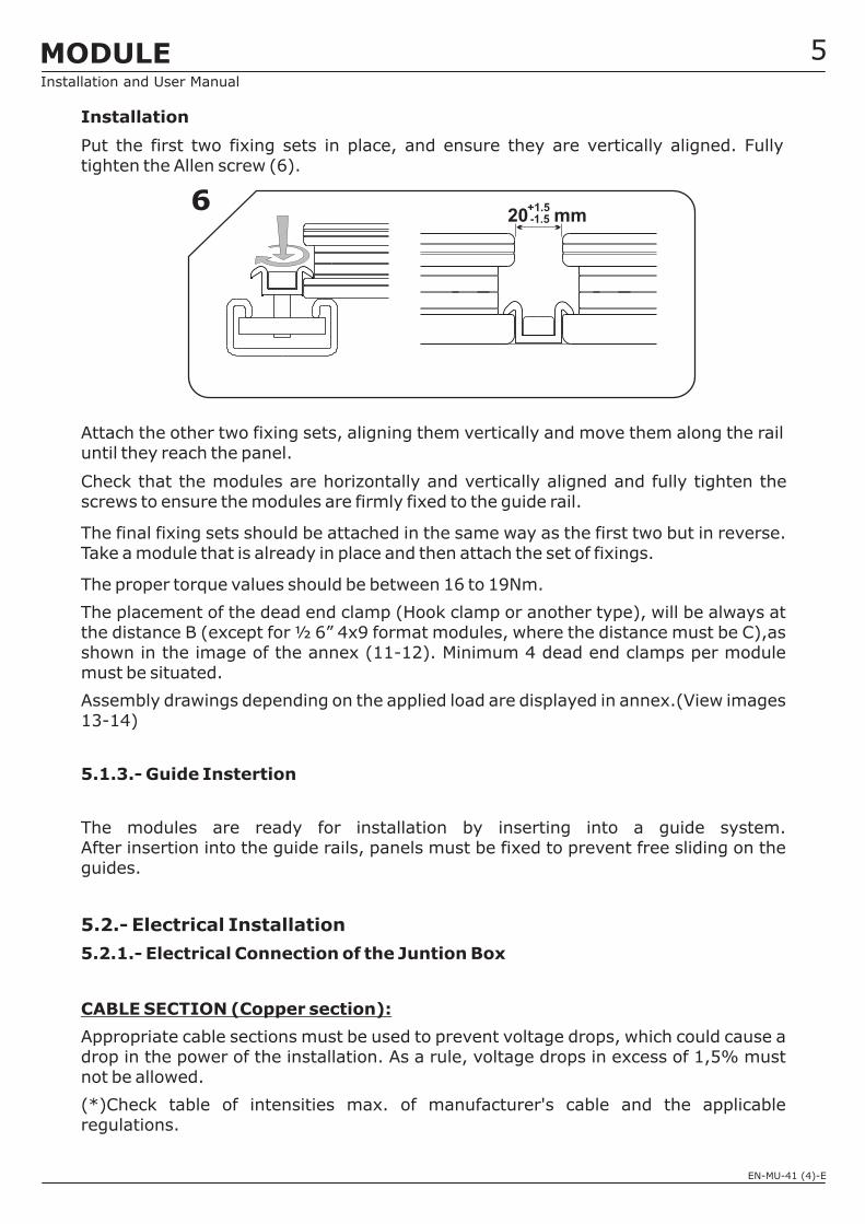
Fixing on standard structures is carried out using the dead-end clamp, the M8x20serrated head Allen screw, flat washer and M8 nut. View image (4).
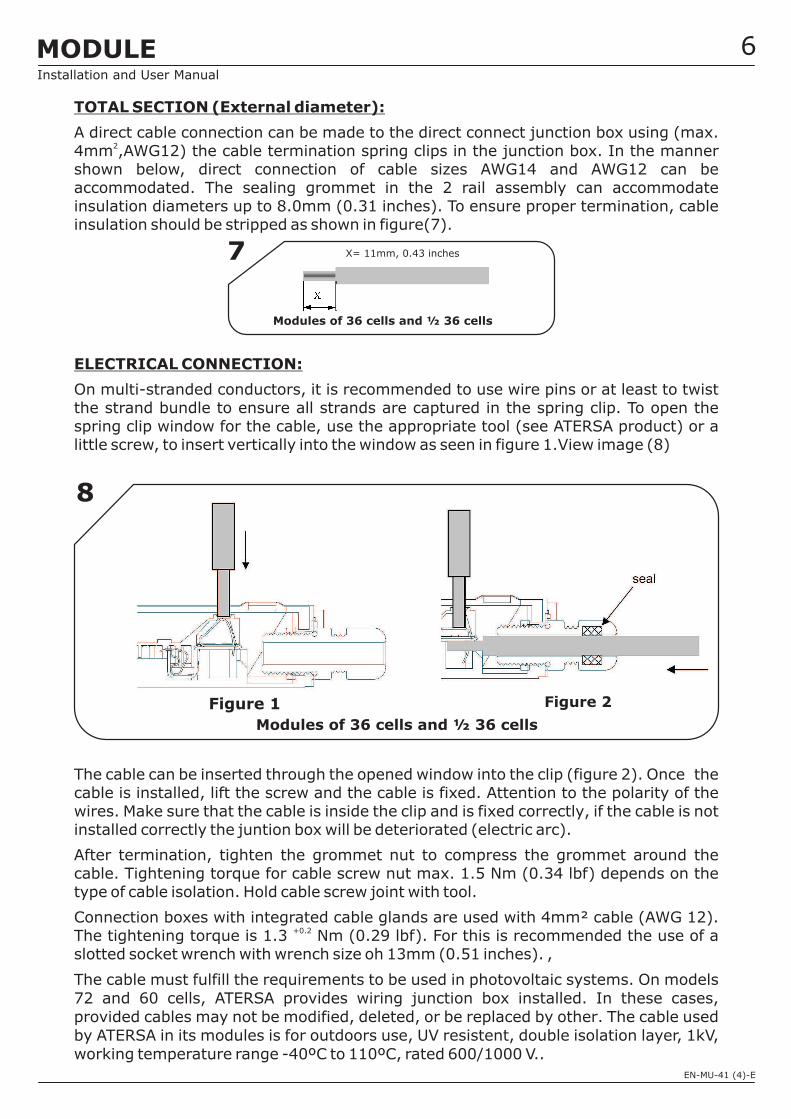
For this type of installation you need a 41x41mm or 41x21mm "U" type perforatedprofile. These elements do not come with the Hook Fixing System.
The assembled fixing should look like the picture shown in next figure:
: In corrosive environments (salt spray), place nylon washers to insulate thepanel from the metal parts of the structure.
Installation on standard structures
Installation on “U” type guide rail:
Hook Fixing System
M8 WHASER
M8 NUT
M8x20 ALLEN SCREW
DEAD-END CLAMP4
M8x20 ALLEN SCREW
DEAD-END CLAMP
M8 GUIDE NUT
5
4MODULEInstallation and User Manual
EN-MU-41 (4)-E
Installation
5.1.3.- Guide Instertion
5.2.1.-
The proper torque values should be between 16 to 19Nm.
The placement of the dead end clamp (Hook clamp or another type), will be always atthe distance B (except for ½ 6” 4x9 format modules, where the distance must be C),asshown in the image of the annex (11-12). Minimum 4 dead end clamps per modulemust be situated.
Assembly drawings depending on the applied load are displayed in annex.(View images13-14)
Appropriate cable sections must be used to prevent voltage drops, which could cause adrop in the power of the installation. As a rule, voltage drops in excess of 1,5% mustnot be allowed.
(*)Check table of intensities max. of manufacturer's cable and the applicableregulations.
5.2.- Electrical Installation
CABLE SECTION (Copper section):
Put the first two fixing sets in place, and ensure they are vertically aligned. Fullytighten the Allen screw (6).
Attach the other two fixing sets, aligning them vertically and move them along the railuntil they reach the panel.
Check that the modules are horizontally and vertically aligned and fully tighten thescrews to ensure the modules are firmly fixed to the guide rail.
The final fixing sets should be attached in the same way as the first two but in reverse.Take a module that is already in place and then attach the set of fixings.
The modules are ready for installation by inserting into a guide system.After insertion into the guide rails, panels must be fixed to prevent free sliding on theguides.
Electrical Connection of the Juntion Box
620 mm-1.5
+1.5
5MODULEInstallation and User Manual
EN-MU-41 (4)-E
TOTAL SECTION (External diameter):
ELECTRICAL CONNECTION:
A direct cable connection can be made to the direct connect junction box using (max.4mm ,AWG12) the cable termination spring clips in the junction box. In the mannershown below, direct connection of cable sizes AWG14 and AWG12 can beaccommodated. The sealing grommet in the 2 rail assembly can accommodateinsulation diameters up to 8.0mm (0.31 inches). To ensure proper termination, cableinsulation should be stripped as shown in figure(7).
On multi-stranded conductors, it is recommended to use wire pins or at least to twistthe strand bundle to ensure all strands are captured in the spring clip. To open thespring clip window for the cable, use the appropriate tool (see ATERSA product) or alittle screw, to insert vertically into the window as seen in figure 1.View image (8)
The cable can be inserted through the opened window into the clip (figure 2). Once thecable is installed, lift the screw and the cable is fixed. Attention to the polarity of thewires. Make sure that the cable is inside the clip and is fixed correctly, if the cable is notinstalled correctly the juntion box will be deteriorated (electric arc).
After termination, tighten the grommet nut to compress the grommet around thecable. Tightening torque for cable screw nut max. 1.5 Nm (0.34 lbf) depends on thetype of cable isolation. Hold cable screw joint with tool.
Connection boxes with integrated cable glands are used with 4mm² cable (AWG 12).The tightening torque is 1.3 Nm (0.29 lbf). For this is recommended the use of aslotted socket wrench with wrench size oh 13mm (0.51 inches). ,
. On models72 and 60 cells, ATERSA provides wiring junction box installed. In these cases,provided cables may not be modified, deleted, or be replaced by other.
rated 600/1000 V..
2
+0.2
The cable must fulfill the requirements to be used in photovoltaic systems
The cable usedby ATERSA in its modules is for outdoors use, UV resistent, double isolation layer, 1kV,working temperature range -40ºC to 110ºC,
7 X= 11mm, 0.43 inches
8
Figure 1 Figure 2
6
Modules of 36 cells and ½ 36 cells
Modules of 36 cells and ½ 36 cells
MODULEInstallation and User Manual
EN-MU-41 (4)-E
For the junction box to maintain its Class II safety standard, the cables must also beClass II.
The ground wire must be .To ground the modules, you must use a stainless steellug terminal and a self-tapping screw between 4,2x4,5mm and 4,2x16mm. Estoirá unido a un terminal de ojete semiaislado de 4mm .Ver imagen (10).
Make sure the lug terminal is placed between the wire and module frame. The wiremust fully clamped with the lug terminal and must make good contact with the frame.
There are two drill holes in the solar modules for this purpose, which are marked with aground connection (Earthing hole 4mm). View image of annex (11-12). The propertorque values should be between 1,5 to 2Nm.
The photovoltaic system will be earthed according to the local and national regulations.
2
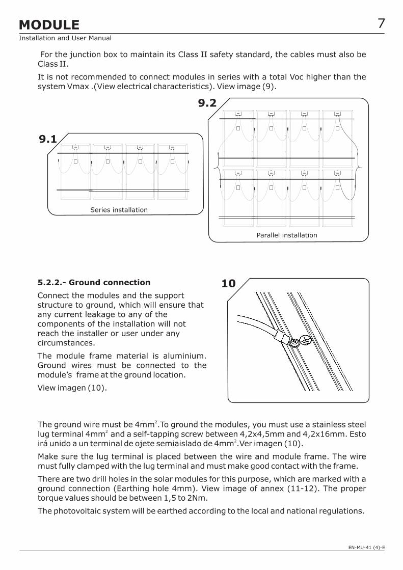
It is not recommended to connect modules in series with a total Voc higher than thesystem Vmax .(View electrical characteristics). View image (9).
4mm4mm
2
2
10
7
Series installation
Parallel installation
9.1
9.2
5.2.2.- Ground connection
Connect the modules and the supportstructure to ground, which will ensure thatany current leakage to any of thecomponents of the installation will notreach the installer or user under anycircumstances.
The module frame material is aluminium.Ground wires must be connected to themodule’s frame at the ground location.
View imagen (10).
MODULEInstallation and User Manual
EN-MU-41 (4)-E
5.2.- Installation and guiding of the electrical cables
All the cables used in the installation must be secured in order to prevent movementsthat could cause damage or breakages.
ATERSA solar modules hardly require any maintenance but you must follow a set ofguidelines to ensure good condition.
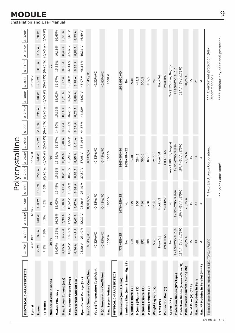
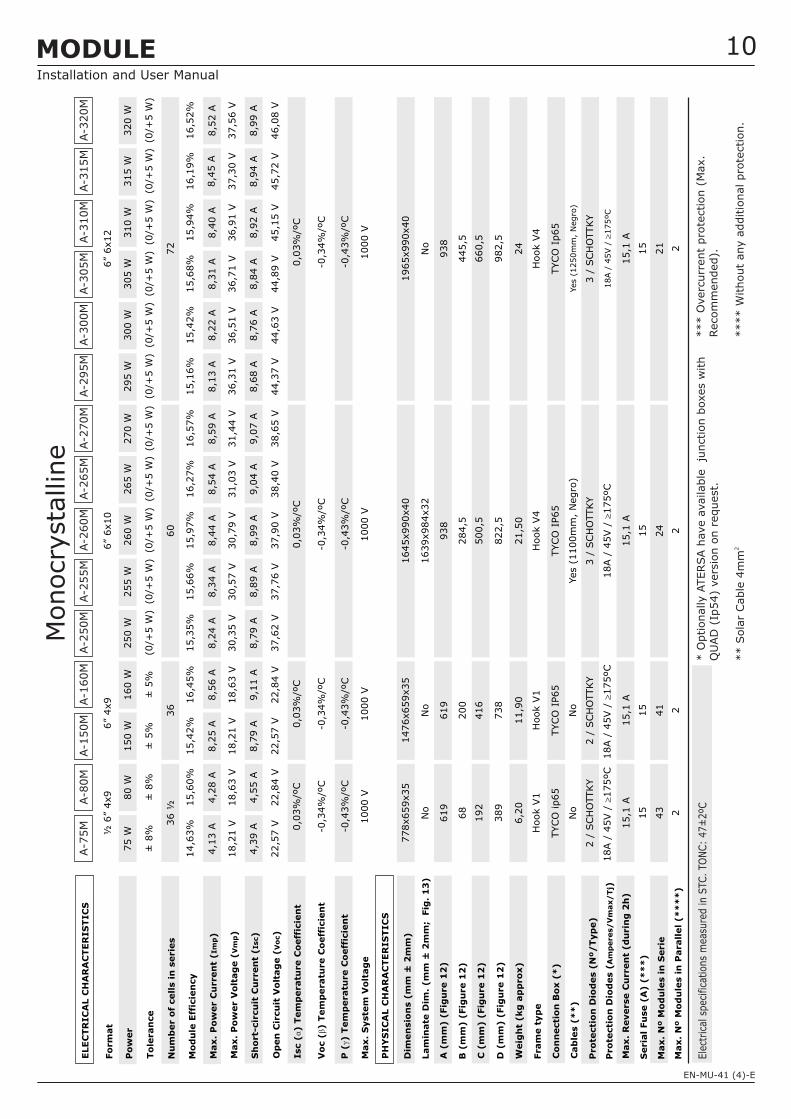
Our solar modules are made from high-efficiency square cells that are capable ofproducing power with low solar radiation. All the models from 75W to 320W have by-pass diodes in the junction box.
The technical characteristics of the modules are shown in the attached table andgrapichs. View table on page 9 (Polycrystalline) and page 10 (Monocrystalline).
ATERSA guarantees the power output for up to 25 years and provides a 10-yearwarranty covering manufacturing flaws.
The modules comply with IEC 61215:2005 and IEC 61730 standards, in addition tobeing manufactured under strict UNE-EN ISO 9001:2008, UNE-EN ISO 14001:2004quality standards.and OHSAS 18001:2007.
6.- MAINTENANCE
7.-
8.-
x
x
x
x
x
x
x
x
x
x
x
x
Maintenance work should be carried out by qualified personnel, as it could involve working withdangerously high voltages.
Check that dirt has not accumulated on the glass of the panel.
Should this be the case, clean the glass with a sponge and soapy water
In case if water is not available,Module can be dry cleaned with the help of a soft cloth or with softsponge to remove dirt, dust.
DO NOT use brushes or abrasive products as they can damage the glass and reduce the powermodule.
DO NOT use any chemical abrasive cleaners, degreasers, or cleaning.
DO NOT use water jet cleaning system.
DO NOT clean the panels at their hottest (midday).
Check the cables and electrical connections.
DO NOT use lubricant oils or sprays to connect the connectors..
Appropriate electrically insulating Personal Protective Equipment (PPE) must be worn during anycleaning or inspection operations.
Check that the mechanical components are not damaged.
TECHNICAL SPECIFICATIONS
GUARANTEE AND CERTIFICATES
According to the norm IEC 61730-1, the application class for this product (ATERSAmodule) is class A, which corresponds to modules working in voltages above 50V orpowers above 240W where the access to a general contact is forecasted. The modulesclasified for security within this category fulfill the requirements for ClassII.
8MODULEInstallation and User Manual
EN-MU-41 (4)-E
* T
yco E
lectr
onic
s C
orp
ora
tion.
** S
ola
r Cable
4m
m2
*** O
verc
urr
ent
pro
tection (
Max.
Recom
mended).
**** W
ithout
any a
dditio
nalpro
tection.
(0/+
5 W
)
14,9
0%
8,0
7 A
8,6
7 A
44,6
7 V
35,9
3 V
(0/+
5 W
)
1645x990x40
1639x984x32
3 /
SCH
OTTKY S
l1010
Yes (
1100m
m,
Negro
)
15,1
6%
8,1
4 A
8,7
8 A
44,8
2V
36,2
3 V
(0/+
5 W
)(0
/+5 W
)
36 ½
778x659x35
619
68
389
6,2
0
No
192
Hook V
1
TYCO
IP65
2 /
SCH
OTTKY S
l1010
No
15
43 2
20,2
5 A
18A /
45V /
175ºC
m
14,6
3%
4,0
5 A
4,2
4 A
23,2
0 V
18,5
2 V
± 8
%
14,3
9%
7,9
8 A
8,4
2 A
22,3
0 V
17,5
4 V
± 5
%
15,4
2%
8,1
0 A
8,4
7 A
23,2
0 V
18,5
2 V
± 5
%
16,4
5%
8,4
3 A
8,8
4 A
23,4
0 V
18,9
9 V
15,6
8%
8,2
9 A
8,8
8 A
37,8
0 V
30,7
6 V
36
1476x659x35
619
200
738
11,9
0
No
416
Hook V
1
TYCO
IP65
2 /
SCH
OTTKY S
l1010
No
41
15 2
20,2
5 A
18A /
45V /
175ºC
m
60
15,9
6,%
8,3
5 A
8,9
5 A
37,9
8 V
31,2
0 V
(0/+
5 W
)
16,2
7%
8,4
0 A
9,0
1 A
38,1
4 V
31,5
5 V
938
284,5
822,5
21,5
0
500,5
Hook V
4
24
1000 V
-0,4
3%
/ºC
-0,3
2%
/ºC
0,0
4%
/ºC
1000 V
-0,4
3%
/ºC
-0,3
2%
/ºC
0,0
4%
/ºC
Ele
ctrica
l sp
ecific
atio
ns
mea
sure
d in S
TC.
TON
C:
47±
2ºC
A-7
5P
A-1
40P
½ 6
”4x9
A-1
50P
6”
4x9
6”
6x10
290 W
295 W
75 W
140 W
150 W
160 W
255 W
260 W
265 W
A-1
60P
A-2
55P
1000 V
-0,4
3%
/ºC
-0,3
2%
/ºC
0,0
4%
/ºC
TYCO
IP65
15 2
20,2
5 A
18A /
45V /
175ºC
m
A-2
60P
A-2
65P
A-2
90P
A-2
95P
A-3
00P
300 W
15,4
2%
8,2
1 A
8,8
9 A
44,9
7 V
36,5
2 V
A-3
05P
305 W
(0/+
5 W
)
15,6
7%
8,2
7 A
8,7
8 A
45,9
7 V
36,8
8 V
A-3
10P
310 W
(0/+
5 W
)
15,9
3%
8,3
5 A
8,8
3 A
46,1
4 V
37,1
4 V
6”
6x12
72
1000 V
-0,4
3%
/ºC
-0,3
2%
/ºC
0,0
4%
/ºC
1965x990x40
938
445,5
982,5
24
No
660,5
Hook V
4
TYCO
IP65
Yes (
1250m
m,
Negro
)
3 /
SCH
OTTKY S
l1010
18A /
45V /
175ºC
m
20,2
5 A
15
21 2
± 5
%(0
/+5 W
)
9
13,6
5%
4,2
2 A
4,4
2 A
23,4
0 V
18,9
9 V
A-8
0P
± 8
%
80 W
A-3
15P
315 W
(0/+
5 W
)
16,1
9%
8,4
3 A
8,8
8 A
46,3
1 V
37,3
7 V
16,4
5%
8,5
1 A
8,9
3 A
46,4
9 V
37,6
1 V
(0/+
5 W
)
320 W
A-3
20P
Poly
cry
sta
llin
eMODULEInstallation and User Manual
Dim
en
sio
ns (
mm
± 2
mm
)
PH
YS
IC
AL C
HA
RA
CTER
IS
TIC
S
Isc (
) T
em
peratu
re C
oeff
icie
nt
α
Vo
c (
) T
em
peratu
re C
oeff
icie
nt
β
Op
en
Cir
cu
it V
olt
ag
e (
)V
oc
Sh
ort-
cir
cu
it C
urren
t (
)Isc
Max.
Po
wer V
olt
ag
e (
)V
mp
Nu
mb
er o
f cell
s i
n s
erie
s
Max.
Syste
m V
olt
ag
e
P (
) T
em
peratu
re C
oeff
icie
nt
γ
Pro
tecti
on
Dio
des (
)A
mp
eres/
Vm
ax/
Tj
Pro
tecti
on
Dio
des
(N
º/
Typ
e)
Seria
l Fu
se (
A) (
**
*)
Max.
Nº M
od
ule
s i
n S
erie
Max.
Nº M
od
ule
s i
n P
arall
el
(*
**
*)
Max.
Reverse C
urren
t (d
urin
g 2
h)
Max.
Po
wer C
urren
t (
)Im
p
Lam
inate
Dim
. (m
m ±
2m
m;
Fig
. 1
3)
ELEC
TR
IC
AL C
HA
RA
CTER
IS
TIC
S
To
leran
ce
A (
mm
) (
Fig
ure 1
2)
B (
mm
)(Fig
ure 1
2)
C (
mm
)(Fig
ure 1
2)
D (
mm
)(Fig
ure 1
2)
Weig
ht
(kg
ap
pro
x)
Fram
e t
yp
e
Co
nn
ecti
on
Bo
x (
*)
Cab
les (
**
)
Fo
rm
at
Po
wer
Mo
du
le E
ffic
ien
cy
EN-MU-41 (4)-E
10
1645x990x40
1639x984x32
3 /
SCH
OTTKY
Yes (
1100m
m,
Negro
)
36 ½
778x659x35
619
68
389
6,2
0
No
192
Hook V
1
TYCO
ip65
2 /
SCH
OTTKY
No
15
43 2
15,1
A
18A /
45V /
175ºC
m
14,6
3%
4,1
3 A
4,3
9 A
22,5
7 V
18,2
1 V
± 8
%
15,6
0%
4,2
8 A
4,5
5 A
22,8
4 V
18,6
3 V
± 8
%
15,4
2%
8,2
5 A
8,7
9 A
22,5
7 V
18,2
1 V
± 5
%
16,4
5%
8,5
6 A
9,1
1 A
22,8
4 V
18,6
3 V
± 5
%
36
1476x659x35
619
200
738
11,9
0
No
416
Hook V
1
TYCO
IP65
2 /
SCH
OTTKY
No
41
15 2
15,1
A
18A /
45V /
175ºC
m
60
16,5
7%
8,5
9 A
9,0
7 A
38,6
5 V
31,4
4 V
(0/+
5 W
)
938
284,5
822,5
21,5
0
500,5
Hook V
4
24
1000 V
-0,4
3%
/ºC
-0,3
4%
/ºC
0,0
3%
/ºC
1000 V
-0,4
3%
/ºC
-0,3
4%
/ºC
0,0
3%
/ºC
A-7
5M
A-8
0M
½ 6
”4x9
6”
4x9
6”
6x10
75 W
80 W
150 W
160 W
270 W
A-1
50M
A-1
60M
1000 V
-0,4
3%
/ºC
-0,3
4%
/ºC
0,0
3%
/ºC
TYCO
IP65
15 2
15,1
A
18A /
45V /
175ºC
m
A-2
70M
A-2
95M
295 W
(0/+
5 W
)
15,1
6%
8,1
3 A
8,6
8 A
44,3
7 V
36,3
1 V
A-3
00M
300 W
(0/+
5 W
)
15,4
2%
8,2
2 A
8,7
6 A
44,6
3 V
36,5
1 V
6”
6x12
72
1000 V
-0,4
3%
/ºC
-0,3
4%
/ºC
0,0
3%
/ºC
1965x990x40
938
445,5
982,5
24
No
660,5
Hook V
4
TYCO
Ip65
Yes (
1250m
m,
Negro
)
3 /
SCH
OTTKY
18A /
45V /
175ºC
m
15,1
A
15
21 2
A-3
05M
305 W
(0/+
5 W
)
15,6
8%
8,3
1 A
8,8
4 A
44,8
9 V
36,7
1 V
(0/+
5 W
)
15,6
6%
8,3
4 A
8,8
9 A
37,7
6 V
30,5
7 V
(0/+
5 W
)
15,9
7%
8,4
4 A
8,9
9 A
37,9
0 V
30,7
9 V
(0/+
5 W
)
15,3
5%
8,2
4 A
8,7
9 A
37,6
2 V
30,3
5 V
255 W
260 W
250 W
A-2
50M
A-2
55M
A-2
60M
16,2
7%
8,5
4 A
9,0
4 A
38,4
0 V
31,0
3 V
(0/+
5 W
)
265 W
A-2
65M
A-3
10M
(0/+
5 W
)
15,9
4%
45,1
5 V
36,9
1 V
8,4
0 A
8,9
2 A
310 W
(0/+
5 W
)
A-3
20M
320 W
16,5
2%
8,5
2 A
8,9
9 A
46,0
8 V
37,5
6 V
16,1
9%
8,4
5 A
8,9
4 A
45,7
2 V
37,3
0 V
(0/+
5 W
)
315 W
A-3
15M
MODULEInstallation and User Manual
Monocry
sta
llin
e
Dim
en
sio
ns (
mm
± 2
mm
)
PH
YS
IC
AL C
HA
RA
CTER
IS
TIC
S
Isc (
) T
em
peratu
re C
oeff
icie
nt
α
Vo
c (
) T
em
peratu
re C
oeff
icie
nt
β
Op
en
Cir
cu
it V
olt
ag
e (
)V
oc
Sh
ort-
cir
cu
it C
urren
t (
)Isc
Max.
Po
wer V
olt
ag
e (
)V
mp
Nu
mb
er o
f cell
s i
n s
erie
s
Max.
Syste
m V
olt
ag
e
P (
) T
em
peratu
re C
oeff
icie
nt
γ
Pro
tecti
on
Dio
des (
)A
mp
eres/
Vm
ax/
Tj
Pro
tecti
on
Dio
des
(N
º/
Typ
e)
Seria
l Fu
se (
A) (
**
*)
Max.
Nº M
od
ule
s i
n S
erie
Max.
Nº M
od
ule
s i
n P
arall
el
(*
**
*)
Max.
Reverse C
urren
t (d
urin
g 2
h)
Max.
Po
wer C
urren
t (
)Im
p
Lam
inate
Dim
. (m
m ±
2m
m;
Fig
. 1
3)
ELEC
TR
IC
AL C
HA
RA
CTER
IS
TIC
S
To
leran
ce
A (
mm
) (
Fig
ure 1
2)
B (
mm
)(Fig
ure 1
2)
C (
mm
)(Fig
ure 1
2)
D (
mm
)(Fig
ure 1
2)
Weig
ht
(kg
ap
pro
x)
Fram
e t
yp
e
Co
nn
ecti
on
Bo
x (
*)
Cab
les (
**
)
Fo
rm
at
Po
wer
Mo
du
le E
ffic
ien
cy
* O
ptionally A
TERSA h
ave a
vailable
ju
nction b
oxes w
ith
QU
AD
(Ip
54)
vers
ion o
n r
equest.
** S
ola
r Cable
4m
m2
*** O
verc
urr
ent
pro
tection (
Max.
Recom
mended).
**** W
ithout
any a
dditio
nalpro
tection.
Ele
ctrica
l sp
ecific
atio
ns
mea
sure
d in S
TC.
TON
C:
47±
2ºC
EN-MU-41 (4)-E
Professional Photovoltaic ModuleEN
ANNEXInstallation and User Manual
Printed on recycled paper
UNE-EN ISO 14001UNE-EN ISO 9001
ER-0979/1997 GA-2009/0396
OHSAS 18001
SST-0134/2012
Dispose of the device at an environmental disposal point when it reaches the end of its useful life
ANNEX
EN-MU-41 (4)-E
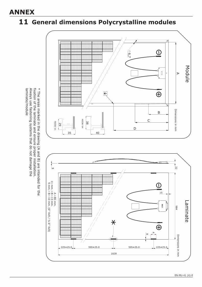
Dim
ensio
ns in
mm
6,7
A
D
C
B
HO
OK V
1
29
35
HO
OK V
4
38
40
B
5
15
A
984
32
* T
he a
reas m
ark
ed in
the d
raw
ing (A
and B
) are
inte
nded fo
r the
fixatio
n o
f the la
min
ate
and e
nsure
pro
per in
sta
llatio
n.
Alw
ays u
se fa
ste
nin
g s
yste
ms th
at d
o n
ot d
am
age th
ela
min
ate
/module
A80 m
m.
11 m
m. B
13 m
m.
9 m
m. B
10 m
m. (6
”4x9 /
6”
4x9)
½
225±25.0 595±25.0 595±25.0 225±25.0
1639
11 General dimensions Polycrystalline modulesD
imensio
ns in
mm
Module
Lam
inate*
ANNEX
EN-MU-41 (4)-E

12
6,7
A
D
C
B
HO
OK V
1
29
35
HO
OK V
4
38
40
225±25.0 595±25.0 595±25.0 225±25.0
B
1639
5
15
*
A
984
32
A80 m
m.
11 m
m. B
13 m
m.
9 m
m. B
10 m
m. (6
”4x9 /
6”
4x9)
½
General dimensions Monocrystalline modules
Module
Lam
inate
ANNEX
Dim
ensio
ns in
mm
* T
he a
reas m
ark
ed in
the d
raw
ing (A
and B
) are
inte
nded fo
r the
fixatio
n o
f the la
min
ate
and e
nsure
pro
per in
sta
llatio
n.
Alw
ays u
se fa
ste
nin
g s
yste
ms th
at d
o n
ot d
am
age th
ela
min
ate
/module
Dim
ensio
ns in
mm
EN-MU-41 (4)-E
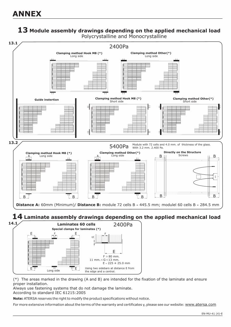
Clamping method Hook M8 (*)Short side
14
Module assembly drawings depending on the applied mechanical load
Clamping method Other(*)Long side
2400Pa
0000000000000
Clamping method Other(*)Short side
0000000000000
0000000000000
Clamping method Hook M8 (*)Long side
0000000000000
0000000000000
Guide instertion
(*) The areas marked in the drawing (A and B) are intended for the fixation of the laminate and ensureproper installation.Always use fastening systems that do not damage the laminate.According to standard IEC 61215:2005
Note: ATERSA reserves the right to modify the product specifications without notice.
For more extensive information about the terms of the warranty and certificates y, please see our website: www.atersa.com
13
13.2
Polycrystalline and Monocrystalline
13.1
Laminate assembly drawings depending on the applied mechanical load14.1
E
0000000000000
F 80 mm.11 mm. G 13 mm.
E 225 ± 25.0 mm=
Laminates 60 cells
Using two sidebars at distance E fromthe edge and a central.
E
G
F
E
Special clamps for laminates (*)
Long side
F
2400Pa
B B
00
00
00
00
00
00
0
A
B B
00
00
00
00
00
00
0
Directly on the Structure
BB
B B
Distance A: Distance B:60mm (Minimum)/ module 72 cells B 445.5 mm; modulel 60 cells B 284.5 mm= =
5400PaClamping method Hook M8 (*)
Long sideClamping method Other(*)
Long side ScrewsA
EE
ANNEX
EN-MU-41 (4)-E
Module with 72 cells and 4.0 mm. of thickness of the glass.With 3.2 mm. 2.400 Pa.