717774-a densitypro
TRANSCRIPT

7/24/2019 717774-A DensityPRO
http://slidepdf.com/reader/full/717774-a-densitypro 1/64

7/24/2019 717774-A DensityPRO
http://slidepdf.com/reader/full/717774-a-densitypro 2/64
TN Densi tyPRO
Gamma Densi ty System Installation Guide
P/N 717774
Revision A

7/24/2019 717774-A DensityPRO
http://slidepdf.com/reader/full/717774-a-densitypro 3/64
© 2005 Thermo Electron Corporation. All rights reserved.
“Microsoft” and “Windows” are either trademarks or registered trademarks of Microsoft Corporation in the
United States and/or other countries.
“HART” is a registered trademark of the HART Communication Foundation.
“Fisher-Rosemount” is either a trademark or registered trademark of Emerson Electric Company.
All other trademarks are the property of Thermo Electron Corporation and its subsidiaries.
Thermo Electron Corporation (Thermo) makes every effort to ensure the accuracy and completeness of this
manual. However, we cannot be responsible for errors, omissions, or any loss of data as the result of errors or
omissions. Thermo reserves the right to make changes to the manual or improvements to the product at any time
without notice.
The material in the manual is proprietary and cannot be reproduced in any form without express written consent
from Thermo.

7/24/2019 717774-A DensityPRO
http://slidepdf.com/reader/full/717774-a-densitypro 4/64
Revision History
Document Number & Revision Level Date Comments
717774 Rev. 1.0 06-00 Initial release
Rev. 2.0 07-01 Released
Rev. A 03-05 Name change

7/24/2019 717774-A DensityPRO
http://slidepdf.com/reader/full/717774-a-densitypro 5/64
This page intentionally left blank.

7/24/2019 717774-A DensityPRO
http://slidepdf.com/reader/full/717774-a-densitypro 6/64
Densi tyPRO Table of Contents
Thermo Electron Corporation i
Table of Contents
Chapter 1 Introduction ...................................................................................................................................... 1-1
Description............................................................................................................................................................ 1-1 Approvals.......................................................................................................................................................... 1-1
Source ............................................................................................................................................................... 1-2 Detector-Transmitter......................................................................................................................................... 1-2 Communications and Measurement Display..................................................................................................... 1-2 Inputs and Outputs ............................................................................................................................................ 1-3 Features............................................................................................................................................................. 1-4
How to Use This Manual....................................................................................................................................... 1-5 Installation Instructions..................................................................................................................................... 1-5 Additional Information ..................................................................................................................................... 1-5 Configuring and Using the Gauge..................................................................................................................... 1-5
Thermo Electron Technical Services..................................................................................................................... 1-6
Chapter 2 Hardware Installation...................................................................................................................... 2-1
Licensing............................................................................................................................................................... 2-1 FM/CSA Hazardous Location Approvals.............................................................................................................. 2-1 Mounting the Gauge (Source and Detector-Transmitter)...................................................................................... 2-2
Mounting Configurations.................................................................................................................................. 2-2 Guidelines for Mounting the Gauge.................................................................................................................. 2-2
Mounting Instructions ........................................................................................................................................... 2-3 Single Chain (Unichain) Mounting Instructions ............................................................................................... 2-3 Dual Chain Mounting Instructions.................................................................................................................... 2-4 Pipe Saddle (Cradle) Mounting Instructions..................................................................................................... 2-6 Pipe Spool Mounting Instructions..................................................................................................................... 2-7 Z-Pipe (Axial) Mounting Instructions............................................................................................................... 2-7
Chapter 3 Wiring Procedures ........................................................................................................................... 3-1
Wiring Instructions................................................................................................................................................ 3-1 Wiring Drawings............................................................................................................................................... 3-2 Initial Wiring Preparations................................................................................................................................ 3-2
Power Supply Wiring............................................................................................................................................ 3-3 DC Power.......................................................................................................................................................... 3-3 AC Power.......................................................................................................................................................... 3-3
Board Wiring......................................................................................................................................................... 3-4 Serial Communications..................................................................................................................................... 3-4 HART Communications ................................................................................................................................... 3-6 Current Output .................................................................................................................................................. 3-6 Flow Input......................................................................................................................................................... 3-6 Relays................................................................................................................................................................ 3-7
Contact Closure (Switch) Inputs ....................................................................................................................... 3-7 Chapter 4 Troubleshooting and Maintenance ................................................................................................. 4-1
Source Housing ..................................................................................................................................................... 4-1 Detector-Transmitter ............................................................................................................................................. 4-1
AC Power Supply Fuse..................................................................................................................................... 4-1 Adding or Replacing Boards............................................................................................................................. 4-2 Factory Wiring.................................................................................................................................................. 4-2 Current Output Jumper Settings........................................................................................................................ 4-3

7/24/2019 717774-A DensityPRO
http://slidepdf.com/reader/full/717774-a-densitypro 7/64
Table of Contents Densi tyPRO
ii Thermo Electron Corporation
Current Output Problems .................................................................................................................................. 4-3 Relay Problems................................................................................................................................................. 4-3
TroubleShooting.................................................................................................................................................... 4-3
Appendix A How to Return Equipment for Service...........................................................................................A-1
Appendix B Parts List ...........................................................................................................................................B-1
Appendix C Specifications ....................................................................................................................................C-1 Operating Principle ...........................................................................................................................................C-1 Power Supply....................................................................................................................................................C-1 FM / CSA Approvals ........................................................................................................................................C-1 Dimensions .......................................................................................................................................................C-1 Operating Temperature .....................................................................................................................................C-1 Serial Interface..................................................................................................................................................C-1 HART Communications ...................................................................................................................................C-1 Current Output ..................................................................................................................................................C-1 Relays................................................................................................................................................................C-1 Contact Closure Inputs......................................................................................................................................C-1 Display..............................................................................................................................................................C-1
Appendix D Drawings ...........................................................................................................................................D-1 868580, Customer Drawing, Installation Layout DensityPRO, Model 9719A/9720A .....................................D-2 868578, Customer Drawing, Installation Wiring, DensityPRO, Model 9719A/9720A....................................D-3 868519, RS-485 Installation & Wiring .............................................................................................................D-4 866778, Mounting Dimensions, Non-Explosion Proof Detector ......................................................................D-5 866777, Mounting Dimensions, Explosion Proof Detector ..............................................................................D-6 867468, Installation Dwg, Detector Assembly, Flat Mount, NEMA 4 Housing...............................................D-7 867469, Installation Dwg, Detector Assembly, Flat Mount, Exp-proof Housing.............................................D-8 867456, Installation Dwg, Source/Detector Assembly Single Chain Mount, NEMA 4 Housing.....................D-9 867465, Installation Dwg, Source/Detector Assembly Single Chain Mount, Exp-proof Housing .................D-10 867466, Installation Dwg, Source/Detector Assembly Two Chain Mount, NEMA 4 Housing......................D-11 867467, Installation Dwg, Source/Detector Assembly Two Chain Mount, Exp-proof Housing ....................D-12 867172, Installation,Gauge Head, Model 9701/9702 Ion Chamber Detector, Two Chain Mount ..................D-13 85726N, Installation Dwg, Gauge Head, Pipe Saddle Mount .........................................................................D-14 861104, Fabrication Details, 1 inch - 3 inch Z-Pipe Section...........................................................................D-15 866670, Mounting Dimensions, 1 inch - 3 inch Z-Pipe Mounting Configuration ..........................................D-16 864163, Fabrication Details, 4 inch Z-Pipe Section........................................................................................D-17 866705, Mounting Dimensions, 4 inch Z-Pipe Mounting Configuration .......................................................D-18 864563, Mounting Dimensions, Source Housing, 100 mCi or Less (Model 5200) ........................................D-19 865453, Mounting Dimensions, Source Housing, 100 mCi or Less (Model 5201) ........................................D-20 865463, Mounting Dimensions, Source Housing, 500 mCi or Less (Model 5202) ........................................D-21 865474, Mounting Dimensions, Source Housing, 2000 mCi or Less (Model 5203) ......................................D-22 865484, Mounting Dimensions, Source Housing, 8000 mCi or Less (Model 5204) ......................................D-23 866666, Mounting Instructions, Remote Manual Actuator, Model 5201-5204 Source Housings ..................D-24

7/24/2019 717774-A DensityPRO
http://slidepdf.com/reader/full/717774-a-densitypro 8/64
Densi tyPRO Chapter 1 Introduction
Thermo Electron Corporation 1-1
Chapter 1 Introduction
The TN DensityPRO Gamma Density System is designed to provide reliable, accurate
process material density measurements for a wide variety of challenging applications.
The gauge is mounted outside of the process vessel and never contacts the processmaterial. The instrument can measure the density of almost any liquid, slurry, emulsion,
or solution.
The instrument can convert the basic density measurement into a variety of output
measurements as appropriate for specific applications, e.g., bulk density or solids content
per unit volume. Given a temperature input, the instrument can compensate the density
measurement relative to a user-specified reference temperature. If a flow input is
provided, the instrument can calculate mass flow. The Setup Menus guide you through
the configuration process to help you quickly complete the gauge setup.
Description
The gauge consists of the source head that contains the radioisotope source and the
detector -transmitter that contains the scintillator detector and electronics. The
radioisotope source emits gamma radiation that passes through the process material. The
detector measures the energy of the radiation arriving at the detector after passing
through the process material (and vessel walls). The gauge determines the density of the
process material by measuring the amount of radiation arriving at the detector, which
varies with the density of the process material.
Approvals
The instrument is certified for use in hazardous locations by FM/CSA as follows.
Model 9719A Detector
• Class II, III, Div. 1, Groups E, F, G
•
NEMA 4 / Type 4Model 9720A Detector
• Class I, II, III, Div. 1, Groups B, C, D, E, F, G
• NEMA 4 / Type 4
Note: Refer to the tag on your gauge to verify the hazardous location approvalinformation for your gauge.
Detector-Transmitter
Source

7/24/2019 717774-A DensityPRO
http://slidepdf.com/reader/full/717774-a-densitypro 9/64
Chapter 1 Introduct ion DensityPRO
1-2 Thermo Electron Corporation
Source
A Cesium (Cs137) radioisotope source is used for most applications. A Cobalt (Co60)
source is available for applications requiring a higher energy source. The radioisotope is
bound in ceramic pellets and double-encapsulated in a pair of sealed, stainless-steel
containers. The resulting source capsule is highly resistant to vibration and mechanical
shock.
The source capsule is further enclosed in the source head, a lead-filled, welded steel
housing. A shaped opening in the lead shielding directs the gamma radiation beam
through the process material towards the detector. Outside of the beam path, the energy
escaping the source head is very low and well within prescribed limits. Closing the
source shutter allows the beam to be “turned off” (the shutter blocks the radiation) during
installation or servicing of the gauge. All source housings meet or exceed the safety
requirements of the U.S. Nuclear Regulatory Commission (NRC) and Agreement State
regulations, refer to the Customer Radiation Safety Manual (717821).
Detector-Transmitter
The gauge uses a scintillator-type detector to measure the radiation reaching the detector
from the source. The detector consists of a special plastic scintillator material, a
photomultiplier tube, and associated electronics. When radiation strikes the plastic
scintillator material, small flashes of light are emitted. As the density of the process
material increases, more gamma radiation is absorbed by the process material and fewer
light pulses are generated by the scintillator material. A photomultiplier tube and the
associated detector electronics converts the light pulses into electrical pulses that are
processed to determine the process material density and related measurement values.
Measurement Calculation
After the gauge calculates the process material density, it can convert the measurementinto a number of forms. For a slurry (solid material in a carrier fluid), the gauge can
provide measurements based on the ratio of solids to carrier. Similar measurements can
be made for emulsions (two different fluids) and for solutions (a solute material dissolved
in a solvent fluid).
If flow data is provided as an input, the gauge can generate mass flow measurements. A
4-20 mA current output from a magnetic flow sensor or from a Thermo Electron
VersaFLO™ fixed or portable flow meter can be input to the instrument.
For applications that require temperature compensation, the gauge can accept a
temperature input to compensate the density measurement for changes in process
temperature.
Communications and Measurement Display
You communicate with the gauge via the RS-485 or the RS-232 serial ports from a
Thermo Hand-Held Terminal (HHT), a PC running TMTComm for Windows® or
terminal emulation software, or a standard ANSI or VT-100 terminal.

7/24/2019 717774-A DensityPRO
http://slidepdf.com/reader/full/717774-a-densitypro 10/64
Densi tyPRO Chapter 1 Introduction
Thermo Electron Corporation 1-3
The HART communication protocol is supported over the 4-20 mA current output with
an optional daughter board. You communicate with the gauge using the standard Fisher
Rosemount 275 HART handheld communicator. Refer to the “DensityPRO/
DensityPRO+ HART Operation Manual,” (717816), for detailed instructions.
Once the gauge has been set up, the primary (density) measurement is displayed on the
external display, if present, and on the remote terminal or HHT.
Inputs and Outputs
Input/Output Characteristics
Type Characteristics Comments
Current output 0-20 mA dc (adjustable range)
Standard Configuration:
Isolated, Loop-powered,
24 Vdc Input, 700 ohm max. load
Alternate Configurations:
1) Non-isolated, Self-Powered,
700 ohm max. load, or
2) Isolated, Self-Powered,700 ohm max. load
Default range is 4-20 mA dc. One
current output is provided on the CPU
board.
Reconfigure current output as:
1) Non-Isolated, Self-Powered by moving a jumper, or
2) Isolated, Self-Powered, requires
“piggy-back” board,(Thermo P/N 886595)
Serial
communications
RS-232: One terminal block
RS-485: One terminal block and one
RJ11 Jack
Full duplex communication with
remote terminal or PC.
Half-duplex communication to PC or
Hand-Held Terminal (HHT).
HART
communications
HART protocol supported over the
4-20 mA current output.
Optional daughter board required.
Relays Two relays (optional) are available onthe AC power/relay board.
Form C SPDT, Isolated, 8 A, 220 Vac
Process alarms and system fault orwarning alarms can be assigned to
control (open/close) relays.
Contact closure
inputs
Two contact closure inputs are
provided on the CPU board.
Execute system commands based on a
user-provided contact switch openingor closure input.
Flow input 4-20 mA current input Current output from a flow sensor can
be input to the gauge. The gauge uses
this input to compute mass-flowreadouts.
Temperature
compensation
Optional Thermo temp. comp. board
- 100 ohm RTD sensor
Temp comp board/sensor allows the
gauge to compensate the densitymeasurement for temperature effects.
External display Optional backlit display of
measurement readouts.
Two lines, 16 characters per line
Up to four measurement readouts can
be displayed at a time.

7/24/2019 717774-A DensityPRO
http://slidepdf.com/reader/full/717774-a-densitypro 11/64
Chapter 1 Introduct ion DensityPRO
1-4 Thermo Electron Corporation
Features
Dynamic Menu System
The Setup Menus guide you through the configuration of the gauge. The “Set up density,
den. alarms, and flow” menu group includes all of the basic parameters and commands
required to quickly configure your gauge. Additional menu groups provide specialized parameters and commands allowing the gauge to be tailored to a wide variety of
applications.
Direct-entry menu shortcuts are also provided, allowing experienced users to access
menu items and commands directly, bypassing the menu system.
Instantaneous Response
Our Dynamic Process Tracking (DPT) ensures that there is no lag time in the system
response to significant changes in process density. When changes occur, the DPT feature
reduces the normal averaging time constant by a factor of eight, ensuring a rapid, yet
smooth output response. When the process stabilizes, a longer time constant is applied to
reduce the fluctuations inherent in radiation-based measurements. In this way, process
density changes are immediately reflected in the transmitter output, while the effects of
statistical variations in the radiation measurement are greatly reduced.
Multiple Readouts
Select up to eight measurement values for display. Available measurement types include
density, bulk density, solids concentration, carrier concentration, ratio of solids to carrier,
bulk mass flow, bulk volume flow, and the rate of change of any these measurements.
Extensive Alarms
You can set up as many as 16 process alarms in addition to system fault alarms andwarning alarms.
Totalizers and Batch Control
You can set up four independent totalizers to “count” elapsed time or cumulative
mass/volume when a flow input signal is provided and a mass/volume-flow measurement
has bee defined. Totalizers can be assigned to drive relays. Relays can be set to open or
close at specified “slow” and/or “stop” counts for batch or sample control.
Output Signals
You can assign any measurement to the 4-20 mA current output, or the measurement
values can be sent to a remote terminal or host computer as serial data. The two contactclosure inputs can be used to activate any system command based on a user-provided
switch input (open or close). Two relay outputs are available on the optional AC
power/relay board.

7/24/2019 717774-A DensityPRO
http://slidepdf.com/reader/full/717774-a-densitypro 12/64
Densi tyPRO Chapter 1 Introduction
Thermo Electron Corporation 1-5
How to Use This Manual
This manual provides guidelines for planning the installation of your gauge, and
instructions for the hardware installation and wiring of the gauge. We suggest that you
read the appropriate chapters of this manual before you begin the installation of your
gauge.
Installation Instructions
Chapter 2 “Hardware Installation,” explains where and how to mount the gauge head
and transmitter.
Chapter 3 “Wiring Procedures,” explains wiring for the detector and transmitter, as
well as optional relays, current outputs, contact closure inputs, and serial communication.
Chapter 4 “Troubleshooting and Maintenance,” describes maintenance and
troubleshooting procedures for the gauge.
Addi tional Information
Appendix A “How to Return Equipment for Service,” provides shipping information
in case you should need to return equipment to Thermo for service.
Appendix B “Parts List,” - refer to this list if you need to order parts.
Appendix C “Specifications,” summarizes the system specifications.
Appendix D “Drawings,” lists the installation drawings and provides reduced-size
copies of drawings.
Configuring and Using the Gauge
When installation is complete, refer to the “DensityPRO Operation Manual” (717784) for
detailed instructions for configuring and operating your gauge.
Refer to the “DensityPRO/DensityPRO+ HART Operation Manual” (717816) for
detailed instructions for the set up and operation of the gauge via the HART protocol.
Refer to the “Model 9733/9734 Hand-Held Terminal Operation Manual” (717797) for
details on communicating with the gauge using the Thermo Hand-Held Terminal.

7/24/2019 717774-A DensityPRO
http://slidepdf.com/reader/full/717774-a-densitypro 13/64
Chapter 1 Introduct ion DensityPRO
1-6 Thermo Electron Corporation
Thermo Electron Technical Services
The Thermo Electron Technical Services Department is ready to assist you with any
installation or setup problems you may have with your gauge.
Main Office
Phone: 512-388-9100
800-736-0801 (USA only)
FAX: 512-388-9200
Emergency/After Hours:
512-388-9310 Radioactive Material Incidents
512-388-9320 Technical Support
Web Site: http://www.thermo.com
Address: Thermo Electron Corporation
Factory Service Department
2555 North IH 35Round Rock, Texas 78664
Canada
Phone: 905-888-8808
FAX: 905-888-8828

7/24/2019 717774-A DensityPRO
http://slidepdf.com/reader/full/717774-a-densitypro 14/64
Densi tyPRO Chapter 2 Hardware Installation
Thermo Electron Corporation 2-1
Chapter 2 Hardware Installation
This section provides guidance for mounting the density gauge. The gauge consists of the
detector-transmitter and the source head.
• Detector-Transmitter: Model 9719A (non-explosion proof) orModel 9720A (explosion proof)
• Source Head: Standard Model numbers include:
5200, 5201, 5202, 5203, 5204, and 5211.
Note: Reduced-size copies of the drawings referenced in this chapter areprovided in Appendix D for your convenience.
Licensing
Warning: The gauge is a nuclear device regulated by federal and/or stateauthorities. You are responsible for knowing and following the
pertinent safety and regulatory requirements. Refer to the CustomerRadiation Safety Manual (717821) for a summary of these requi rements.
Moving or removing an installed source housing, or any assembly thatincludes a source housing, requires a person who is specificallylicensed to install and commission Thermo Electron source heads.
Your general license permits you to own and install all of the gauge’s components,
including the source head. However, you may not commission the gauge (remove the
shipping bolt and open the source shutter for the first time) without a specific license
authorizing radiation commissioning of the gauge.
For assistance obtaining a specific license, commissioning, or decommissioning thegauge, contact Thermo Electron Technical Services.
FM/CSA Hazardous Location Approvals
The FM/CSA hazardous area approvals are listed below.
Warning: Do not locate the unit in any hazardous area other than those approved.
Refer to the equipment tag for the specific approvals applicable to theconfiguration of your gauge prior to installing the gauge.
Model 9719A Detector
• Class II, III, Div. 1, Groups E, F, G
• NEMA 4 / Type 4
Model 9720A Detector
• Class I, II, III, Div. 1, Groups B, C, D, E, F, G
• NEMA 4 / Type 4

7/24/2019 717774-A DensityPRO
http://slidepdf.com/reader/full/717774-a-densitypro 15/64
Chapter 2 Hardware Installation DensityPRO
2-2 Thermo Electron Corporation
Mounting the Gauge (Source and Detector-Transmitter)
Mounting Configurations
The optimum gauge mounting configuration depends on the application; however, the
source head and the detector are typically mounted together on the opposite sides of a
pipe. The following mounting options are supported for the instrument:
• Chain mount
− Single chain (unichain)
− Dual chain
• Cradle-type (saddle) clamp
• Pipe spool with gauge head pre-installed
• Z-pipe (axial) mount for small diameter pipes
The chain mount is the most frequently used mounting configuration this allows the unit
to be mounted on a range of pipe sizes using the same mounting hardware.
Note: Moving the gauge to a pipe with a different diameter may require changingthe radiation source size. Call Thermo for assistance.
Guidelines for Mounting the Gauge
• Power requirements for the detector-transmitter:
− 24 Vdc ±20%, 12VA, at detector input, or
− 12 Vdc ±30%, 12VA, (w/12-to24 Vdc converter option), or
− 115/230 Vac (±15%), 50/60 Hz, 12 VA (w/AC Power option).
• The operating temperature range is –40º C to 70º C (–40º F to 160º F).
•
Make sure there is enough clearance to install and service the gauge head. (Referto the appropriate drawings for your type of gauge and mount.)
• Position the gauge head so the radioactive source identification tag is visible.
Mount the source housing so the tag is upright.
• Avoid locations where process overflow, debris, or other material can collect in
the beam path (especially in the shutter mechanism).
Regardless of what mounting configuration is used, it is important to align the beam path
(the centerline of the source housing) as closely as possible with the centerline of the
detector housing. Be sure to mount the gauge head securely, since any movement or
change in alignment can affect the gauge’s calibration.
For best performance the beam must pass through a representative cross-section of the process material being measured.
• It is best to mount the gauge head on a vertical section of pipe. This keepssuspended solids from settling out of the measured area. (The gauge measures
only the material that passes through the beam.)

7/24/2019 717774-A DensityPRO
http://slidepdf.com/reader/full/717774-a-densitypro 16/64
Densi tyPRO Chapter 2 Hardware Installation
Thermo Electron Corporation 2-3
• To mount the gauge head on a horizontal pipe –
− Position the beam path at a 30 to 45 degree angle from vertical. This position
tends to average density variations caused by settling, while reducing the
effect of any trapped gases or solids that accumulate in the top or bottom of
the pipe.
− If the process material is a solution, a light slurry, or a single-phase liquidthat will not separate, the gauge head can be mounted such that the beam is
horizontal.
• If the process material is a slurry, position the gauge head as far as possible from
any elbows, tees, or valves - these tend to separate suspended solids. Position the
beam path in the plane of the upstream elbow so the measurement includes any
uneven distribution caused by the fitting.
Figure 2.1 Gauge Installation Examples
Mounting Instructions
The following sections provide installation details for the various mounting
configurations.
Refer to the following drawings for detector dimensions.
• Drawing 866778 Model 9719A detector (NEMA 4 Housing)
• Drawing 866777 Model 9720A detector (Exp-Proof Housing)
Caution: Use proper lifting procedures during installation to avoid injury.
Do not over-tighten the bolts.
Single Chain (Unichain) Mounting Instructions
The single chain or unichain mount is only available with the Model 5211 source
housing. In this mounting configuration, a mounting chain is inserted through an eye bolt
in the rear of the source housing. The two ends of the chain are wrapped around the pipe
and engaged in slotted tabs in the detector housing.
X
XX
X - Improper Gauge Head Mounting
- Correct Gauge Head Mounting

7/24/2019 717774-A DensityPRO
http://slidepdf.com/reader/full/717774-a-densitypro 17/64
Chapter 2 Hardware Installation DensityPRO
2-4 Thermo Electron Corporation
The following steps describe the installation of the gauge head using a single chain
mount. Also refer to the following drawings for mounting details.
• Drawing 867456 Model 9719A detector (NEMA 4 housing), or
• Drawing 867465 Model 9720A detector (explosion-proof housing).
The mounting hardware kit shipped with the gauge should include:
− 1 Eye Bolt (.500-13 x 3 in.), 1 Nut (.500-13), 1 Belleville Washer
− 1 Chain
1. Insert the eye bolt through hole in rear of source housing. Place Belleville
washer, cupped-side first, onto the eye bolt. Thread the nut on the eye bolt until
the bolt just begins to come through the nut.
2. Insert the chain through the eye bolt so that approximately the same length of
chain extends on each side of the eye bolt.
3. Position the source housing and detector housing so that the V-shaped mounting
features center the housings on the pipe.
4. With the axis of the source housing and detector housings aligned, attach one end
of the chain in the slotted tab on one side of the detector housing. Pull the chain
tight on the other side and attach it into the slotted tab on the other side of the
detector housing.
5. Maintain alignment of the housings and tighten the nut on the eye bolt ~1/2 turn
past point where Belleville washer becomes fully flattened.
Note: There must be an even number of chain links between the slotted tabs sothat there will be an equal number of links on both sides.
Dual Chain Mounting Instructions
In the dual chain mount, two mounting chains are wrapped around the pipe with their
ends engaging keyhole-shaped openings in the source head mounting plate. The detector
housing is then clamped to the two chains’ center links (opposite the source mounting plate) by tensioning bolt assemblies as illustrated in the photograph below.

7/24/2019 717774-A DensityPRO
http://slidepdf.com/reader/full/717774-a-densitypro 18/64
Densi tyPRO Chapter 2 Hardware Installation
Thermo Electron Corporation 2-5
The following steps describe the installation of the gauge head using a dual chain mount.
Refer to the following drawings for mounting details.
• Drawing 867466 Model 9719A detector
• Drawing 867467 Model 9720A detector
1. Use the table on page 2-6 to determine the number of chain links to threadthrough the keyhole slots. Count the links and mark the links that will be engaged
at each end of the two chains (four links in all).
2. Partially assemble the two tensioning bolts (hardware kit 885826) in the
following order:
− 1 tensioning bolt (large),
− 1 chain - place center ring of chain over the bolt head,
− 1 bar nut - position the guard tube towards the bolt head,
− 1 special nut - thread nut securely onto the bolt end. After the special nut is
fully threaded, thread the bar nut back down the bolt so that it rests against
the special nut.3. From the pipe side of the source mounting plate, thread one end of a chain
through the plate’s top keyhole opening until you reach one of the four end links
you marked in Step 1. Engage this link by sliding it into one of the keyhole slots.
4. Thread one end of the other chain through the bottom keyhole and engage the
marked link as you did with the top chain.
5. Position the source housing mounting plate on the pipe. If necessary, use a lift,
hoist, or other means to hold it in position.
6. Pass the center part of the upper and lower chains around the pipe and thread
their ends through the corresponding keyholes. Engage the marked links in the
empty slots.
Note: All four chain ends must engage at the same link. To make an adjustment,adjust all four chain ends by the same amount. Make sure the chain doesnot twist as you wrap it around the pipe. You may have to adjust chain links(thread more or fewer links through each slot) to allow for pipe sizetolerance, insulation, and so forth. Start with about 10 cm (4 inches) of play.
7. Position the detector on the pipe, opposite the source mounting plate. If
necessary, use a lift, hoist, or other means to hold it in position.
8. To secure the detector and the source head mounting plate on the pipe:
− Position the upper chain (including the tensioning bolt assembled in Step 1)
over the detector’s top mounting arm.
−
Place a spacer ring and then two Belleville washers (concave sides together)onto the pilot end of the special nut.
− Insert the pilot end of the chain tensioning bolt into the hole in the top
detector mounting arm and tighten the chain tensioning bolt finger-tight.
− Repeat the previous three steps for the lower chain.
9. Alternately and uniformly tighten the chain tensioning bolts until the spacers are
just touching the mounting arms.

7/24/2019 717774-A DensityPRO
http://slidepdf.com/reader/full/717774-a-densitypro 19/64
Chapter 2 Hardware Installation DensityPRO
2-6 Thermo Electron Corporation
10. Place the loose ends of the upper chain over the top edge of the source mounting
plate so they won’t interfere with the source housing installation.
11. Position the source housing so its four mounting holes engage the four studs on
the mounting plate. If necessary, use a lift, hoist, or other means to hold it in
position.
12. Use the provided lock washers and nuts to secure the source housing.
Table 2-1 Number of Chain Links to Engage for Dual Chain Mount
Use Chain Part No. 867103
Models 9719A &
9720A
Models 9719A &
9720A Pipe Size
(inches) Links
From
Center
Links
From
End
Links
From
Center
Links
From
End
2 7 23 6 24
2.5 7 23 6 243 8 22 7 23
3.5 8 22 7 23
4 9 21 8 22
5 10 20 9 21
6 12 18 11 19
8 14 16 13 17
10 17 13 16 14
12 20 10 19 11
14 21 9 20 10
16 24 6 23 7
18 25 5 24 6
Pipe Saddle (Cradle) Mounting Instructions
A pipe saddle mount (shown below) is a pair of identical mounting plates that are bolted
together on opposite sides of the process pipe.

7/24/2019 717774-A DensityPRO
http://slidepdf.com/reader/full/717774-a-densitypro 20/64
Densi tyPRO Chapter 2 Hardware Installation
Thermo Electron Corporation 2-7
Refer to drawing 85726N and use the following steps to install a gauge head with a pipe
saddle mount:
1. Assemble the two halves of the saddle mount onto the process pipe using the
supplied nuts, bolts, and washers. Do not tighten the nuts and bolts yet, just
thread them together.
2. Adjust the saddle mount halves so the mounting plates are parallel and even witheach other. Then tighten the bolts evenly so the clamp ends are the same distance
apart on both sides of the pipe.
3. Bolt the detector and source housings to the mounting plates on either side of the
pipe saddle.
4. Tighten all bolts securely so the gauge head components cannot shift positions.
Pipe Spool Mounting Instructions
A pipe spool is normally a 30-inch section of pipe with either mounting plates or acomplete gauge head already installed. Often, the customer sends a length of the required
pipe to Thermo to be converted into a pipe spool mount.
Warning: Use correct pipe fitting techniques suitable for the pipe being used andthe process material that the p ipe will handle.
Use the following steps to install a gauge head with a pipe spool mount:
1. Assemble the pipe spool into the existing pipe.
2. Position the source housing so its identification tag is upright.
3. If the detector and source housings are not already installed, bolt them to the
mounting plates on either side of the pipe saddle.
4. Tighten all bolts securely.
Z-Pipe (Axial) Mounting Instructions
A Z-pipe mount is used for small pipes, four inches in diameter or less. It uses a Z-shaped
pipe section so the gamma rays can travel along the pipe’s axis for several inches. This
lets the beam pass through more process material so the material’s density can be
measured more reliably.
Depending on the application, the user typically fabricates the Z-pipe section and then
either assembles it into the mounting fixture or sends it to Thermo for assembly.
Fabricating and Assembling the Z-Pipe
To fabricate the Z-pipe, refer to the drawings for your specific application.
• Drawing 861104 Z Pipe Fabrication Details (1-3 in. pipe sizes)
• Drawing 864163 Z Pipe Fabrication Details (4 in. pipe)
Carefully note the tolerances for each dimension. Any variation in the Z-pipe dimensions,
especially in the bracket placement, can lead to misalignment causing inaccurate readings
or no readings at all.

7/24/2019 717774-A DensityPRO
http://slidepdf.com/reader/full/717774-a-densitypro 21/64
Chapter 2 Hardware Installation DensityPRO
2-8 Thermo Electron Corporation
Z-Pipe Installation
Refer to the following drawings for mounting dimensions.
• Drawing 866670 Z Pipe Mount (1-3 in. pipe sizes)
• Drawing 864163 Z Pipe Mount (4 in. pipe)
Caution: If a lead doughnut is provided with the mounting assembly, make sureits inside diameter matches the pipe’s outside diameter.
While assembling the mount, clamp the doughnut to the axial portion ofthe Z-pipe (between the source and detector) as close to the center aspossible.
Warning: If the process pipe is not strong enough to support the gauge head andmounting assembly, you must provide additional support for the gaugehead.
After the pipe and mount are assembled, you can install the gauge head using the steps in
“Pipe Spool Mounting Instructions” on page 2-7, with the following additional notes:
• If your gauge is supplied with a large lead plate with a one- to two-inch hole in
the center, the plate should be mounted between the detector and the mounting
plate.
• If your gauge is supplied with a thin steel plate with a small lead disk, the plateshould be mounted between the source housing and the mounting plate, with the
disk towards the pipe (the disk should fit in the hole in the mounting plate).

7/24/2019 717774-A DensityPRO
http://slidepdf.com/reader/full/717774-a-densitypro 22/64
Densi tyPRO Chapter 3 Wiring Procedures
Thermo Electron Corporation 3-1
Chapter 3 Wiring Procedures
The detector-transmitter electronics includes the following boards.
• CPU / DC power board (required)
• AC power and/or relays board (optional)
This optional board is available in three configurations.
AC power with no relays
AC power with 2 relays
2 relays only
• Isolated, self-powered, 4-20 mA current output: an optional piggy-back board
that mounts on the CPU board.
The required wiring steps are:
• connect the power supply to the gauge, and
• connect a remote computer terminal or Hand-Held Terminal to the gauge via the
serial communication ports.
Additional, optional wiring may include:
• 4-20 mA current output,
• relay contacts,
• contact closure inputs,
• optional, remote display (two line by 16 characters),
• Flow sensor input (4-20 mA).
Wiring Instructions
The CPU board provides the connections for the system DC power input, the RS-232 andRS-485 serial ports, the current output, the contact closure inputs, and the optional
external display. All wiring must be done in accordance with applicable codes, using
approved conduit, boxes, and fittings.
Danger: Remove all power from the unit before making any connections.Electrocution can result if power is present.
Warning: All wiring must be done by qualified individuals in accordance with
applicable codes such as the NEC (National Electric Code) ANSI/NFPA70 specifications or the Canadian Electrical Code Part 1.
Warning: Before wiring the gauge, verify that the source shutter is in the closed(OFF) position.

7/24/2019 717774-A DensityPRO
http://slidepdf.com/reader/full/717774-a-densitypro 23/64
Chapter 3 Wiring Procedures Densi tyPRO
3-2 Thermo Electron Corporation
Wiring Drawings
The Installation Layout drawing (868580) provides general guidance for routing the
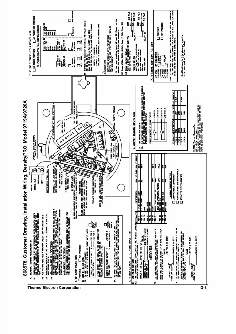
cables to the unit. The installation wiring drawing (868578) describes the function and
wiring requirements for each connector on the CPU/DC power board and on the optional
AC power/relay board. The wiring drawing also shows cable requirements, power
requirements, and grounding locations.
The wiring label on the top of the detector-transmitter chassis also provides connector
wiring information for the CPU/DC power and the AC power /relay boards. Drawing
868519 provides additional instructions for wiring the RS-485 serial port.
Initial Wiring Preparations
Warning: Do not apply power to the unit in any hazardous area unless the safetyground is properly wired inside the unit and the cover is properlyinstalled.
Note: Connect the AC wiring Earth ground to the internal safety groundterminal as shown in the wiring diagram. Refer to “AC Power” on page3-3, if you need to change the AC supply voltage from 115 V to 230 V orvice versa.
Warning: Hazardous Location Installations – The cable entries must be sealedper the Installation Layout Drawing (868580).
Non-Hazardous Location Installations – The cable entries into theenclosures must be sealed to prevent passage of gas or vapors. Thesealing compound should not be affected by the surroundingatmosphere or liquids. The minimum thickness of the sealingcompound should be 5/8 in (16 mm).
If metal conduit is used, the conduit must be grounded.
Use the following procedure for wiring the detector-transmitter:
1. Make sure all source shutters are in the “OFF” position.
2. Make sure all power to the gauge is turned off.
3. Remove the housing access cover. Loosen the screw on the cover retaining
bracket and slide the bracket off of the housing cover. Unscrew the housing
access cover (two lugs are provided on the top of the cover to aid in the removal
of the cover).
4. Remove the cable conduit plugs only from the hole(s) that will be used. As
shown in the installation layout drawing, lay one conduit for the DC power inputand signal cables, and if applicable, a second conduit for the AC power input and
relays. Route the cables into the detector housing and connect the input power
and signal wires as shown in the installation wiring diagram.
5. Pull each cable through the correct conduit fitting and into the enclosure. Leave
approximately 150 mm (6 inches) for strain relief. Secure the conduit, making
sure it is completely sealed.

7/24/2019 717774-A DensityPRO
http://slidepdf.com/reader/full/717774-a-densitypro 24/64
Densi tyPRO Chapter 3 Wiring Procedures
Thermo Electron Corporation 3-3
6. To complete the wiring of the detector-transmitter, follow the procedures
described in the “Power Supply Wiring” and the “Board Wiring” sections below.
7. When the wiring is complete, replace the detector housing cover and secure the
cover retaining bracket.
Power Supply Wiring
The maximum input power requirement is 6 VA.
Note: To meet the requi rements of CSA 1010.1, an external switch or circuitbreaker must be installed to allow the power source to be disconnectedfrom the gauge. In addition, protective bond ing (grounding) must always beprovided, even if a DC power source is used.
DC Power
The Model 9719A/9720A scintillation detector is designed to operate on 24 Vdc (± 20%).
When the optional 12-to24 Vdc converter board is installed, the detector can operate on12 Vdc (± 30%). In either case, the input connector for the DC source voltage wiring is
located on the CPU board. Refer to the installation wiring drawing.
Note: To meet the requirements of CSA 1010.1, the input DC terminals shall besupplied from an SELV (Safety Extra Low Voltage) source.
AC Power
If the optional AC power board is installed, the gauge may be operated using either 115
or 230 Vac. The AC supply voltage is set by the 115/230 Vac selector switch on the AC power board.
Warning: Applying 230 Vac with the selector switch in the 115 Vac position wil ldamage the equipment.
The AC selector switch is located behind (below) the connectors on the top edge of the
AC power/relay board. To access the selector switch, it is necessary to remove the screws
that hold the detector-transmitter unit in the housing and lift the detector-transmitter unit
several inches out of the housing.
Caution: For reliable operation and to maintain safety approval, the F1 fuse on
the AC power board must only be replaced with an approved fuse.Refer to the Installation Wiring Diagram, Drawing 868580.
If both AC and DC input power are supplied to the detector, the detector will draw power
from whichever source provides the higher DC voltage.
!

7/24/2019 717774-A DensityPRO
http://slidepdf.com/reader/full/717774-a-densitypro 25/64
Chapter 3 Wiring Procedures Densi tyPRO
3-4 Thermo Electron Corporation
Board Wiring
DANGER: Remove all power from the unit before making any connections.Electrocution can result if power is present.
Warning: All wiring must be done by qualified individuals in accordance withNational Electric Code (NEC) ANSI/NFPA 70 specifications or theCanadian Electrical Code Part 1. For intrinsically safe systems, refer to
ANSI/ISA RP 12.6.
If metal conduit is used, it must be grounded.
After completing the initial wiring preparations, use the following procedure to complete
the wiring of the detector-transmitter. For each cable to be connected, refer to the wiring
label on the top of the chassis or to the installation wiring diagram. You will need a
screwdriver with a 1/8-inch blade to connect the wires to the screw terminal connectors.
1. Make sure all source shutters are in the “OFF” position.
2. Make sure all power to the gauge is turned off.
3. To remove the housing access cover, loosen the screw on the cover retaining
bracket and slide the bracket off of the housing cover. Then, unscrew the housing
access cover (two lugs are provided on the top of the cover to aid in removal).
4. Connect the cable to the appropriate connector on the board as follows:
− Remove the screw–terminal connector from the on-board connector. If the
connector is tight, brace the board with your hand to remove the screw-
terminal connector, but be careful to not touch any circuit components.
− Loosen the terminal screws on the connector. Insert the wires into the
connector and make connections as shown in the installation wiring drawing.
− Tighten the terminal screws to secure the wires. Replace the connector on the
board when all wires are secured.
5. Install the housing cover. For the explosion-proof enclosure, secure the cover
retaining bracket.
Serial Communications
The gauge provides both an RS-232 single-drop and an RS-485 multi-drop serial
interface. Screw-terminal connectors for both ports are located on the CPU board.
The RS-485 connector includes the +8 Vdc required to power the Thermo Hand-Held
Terminal (HHT) as well as the +Data and –Data connections. An RJ-11 (phone jack)
connector is also provided for the RS-485 port. The HHT can be connected directly to theRJ-11 connector.
Both the RS-232 and RS-485 ports provide independent access to the measurement
readings and software functions. Both ports are always active and can be used to display
measurements. The Setup Menus, however, can only be accessed by one port at a time.

7/24/2019 717774-A DensityPRO
http://slidepdf.com/reader/full/717774-a-densitypro 26/64
Densi tyPRO Chapter 3 Wiring Procedures
Thermo Electron Corporation 3-5
RS-485 Wiring
To connect the serial (COM) port on a PC to the RS-485 port on the gauge requires an
RS-485-to-RS-232 converter (Thermo part no. 670045).
• Connect +Data and –Data on the RS-485 connector (located on the CPU board)
to the corresponding connections on the RS-485-to-RS-232 converter.
• Connect the RS-485-to-RS-232 converter to the PC using a standard DB-9 serial
cable.
Refer to the RS-485 installation wiring drawing (868519) and the Wiring drawing
(868578) for details.
Note: Party-line Communications – Initial Setup!
To communicate with multiple gauges via an RS-485 party-line, eachunit must be assigned a unique unit identification number so it can beaddressed individually. All gauges are assigned unit number 0 (zero) bydefault.
To assign a unique unit number to each gauge, you must be able tocommunicate with each gauge individually. You must be able todisconnect each gauge from the party-line in turn and thencommunicate with the disconnected gauge directly. Alternately, youmust remove power from all gauges except one, then assign a unitnumber to the single powered gauge. Repeat this procedure for theremaining gauges.
Note: If you have trouble using another device on the RS-485 chain, verify that itis properly terminated for its pos ition on the chain. To terminate a device,
connect a 120 resistor between its RS-485 +/– data terminals. Neverterminate more than the first and last device in the chain.
RS-232 Wiring
The serial port on a PC (COM1 or COM2) can be connected directly to the RS-232 port
on the gauge. This requires five wires - ground, transmit (TX), receive (RX), RTS and
CTS. The connections between the gauge RS-232 port (J3 connector) and the PC serial
port are summarized in the table below for standard DB-9 and DB-25 PC serial port
connectors.
DensityPRO Gauge
J3 Connector
PC Serial Port
DB-9 Connector
PC Serial Port
DB-25 Connector
J3-2 RX Pin 3 Pin 2J3-3 TX Pin 2 Pin 3
J3-4 RTS Pin 8 Pin 5
J3-5 CTS Pin 7 Pin 4
J3-6 GND Pin 5 Pin 7

7/24/2019 717774-A DensityPRO
http://slidepdf.com/reader/full/717774-a-densitypro 27/64
Chapter 3 Wiring Procedures Densi tyPRO
3-6 Thermo Electron Corporation
Using Serial Communications
To communicate with the gauge from a PC requires that the PC be running TMTComm
for Windows communications software or other terminal emulation software.
The default communication settings for the RS-232 and RS-485 ports of the gauge and
for the Thermo Hand-Held Terminal are:
• 7 data bits,
• even parity,
• 1 stop bit, and
• 9600 baud data rate.
Refer to the user guide for additional details about setting up and using serial
communications.
HART Communications
The HART communication protocol is supported over the 4-20 mA current output with
an optional daughter board. You communicate with the gauge using the standard Fisher
Rosemount 275 HART handheld communicator. Refer to the “DensityPRO HARTOperation Manual” (717816) for detailed instructions.
Current Output
The current output is programmable between 0 and 20 mA; however, the minimum
current output is ~3 mA. The maximum load is 800 ohms. Refer to the installation wiring
diagram (Drawing 868578) for details.
The default configuration for the current output is isolated, loop-powered. A jumper is placed across pins 4 and 5 of the 14-pin header J7, located below the RS-484/RS-232
connectors on the CPU.
• Connect the +24 Vdc loop-power input to Pin 7 of connector J10.
• Connect the +Iout (current output) signal, Pin 6 of J10, to one side of the user
load.
• Connect the other side of the user load to the return of the 24 V loop-power
supply.
Alternately, the current output can be reconfigured as a non-isolated system-powered
output by moving the jumper from pins 4 and 5 to pins 3 and 4 on header J7.
To configure the current output as isolated, system-powered, remove all jumpers from J7
and install the optional daughter board, Thermo P/N 886595.
Flow Input
There is also provision on the CPU board for a user-provided 4-20 mA Flow (AUX)
input (pins 1/2 of connector J10). Refer to the user guide (717784) for details on how to
configure the gauge to use the flow input signal.

7/24/2019 717774-A DensityPRO
http://slidepdf.com/reader/full/717774-a-densitypro 28/64
Densi tyPRO Chapter 3 Wiring Procedures
Thermo Electron Corporation 3-7
Relays
Two relays can be provided as an option on the AC power/relay board. (A factory-
installed jumper across pins 4 and 5 of header J11 indicates to the gauge that the optional
relays are installed. Refer to the installation wiring drawing (and the wiring label on top
of the detector-transmitter chassis) for wiring details. Relay contacts are Form C SPDT,
isolated 8 A, and 220 Vac.
Contact Closure (Switch) Inputs
The contact closure inputs are dry contact inputs between ground and Switch 1 and
ground and Switch 2. The gauge can be configured via software settings to execute a
command or other function upon a user-provided contact opening or closing. Refer to the
user guide (717784) for instructions for assigning commands to the contact closure
inputs.

7/24/2019 717774-A DensityPRO
http://slidepdf.com/reader/full/717774-a-densitypro 29/64
This page intentionally left blank.

7/24/2019 717774-A DensityPRO
http://slidepdf.com/reader/full/717774-a-densitypro 30/64
Densi tyPRO Chapter 4 Troubleshooting and Maintenance
Thermo Electron Corporation 4-1
Chapter 4 Troubleshooting and Maintenance
The Thermo Electron Technical Services Department is ready to assist you with any
problems you may have with your gauge. Thermo Electron provides Field Service,
Factory Service, and replacement parts. Experienced service representatives are availableto help. A 24-hour phone number is provided for emergency service calls.
Source Housing
Periodically check the source and remove any debris that may have accumulated in the
beam path between the source housing and the outer wall of the process vessel.
Warning: Do not place your hand between the source and the tank. Use a brushor other tool to remove any accumulated debris.
Also check the shutter to make sure it works correctly. For source housings with anexposed shutter lever pivot, you can apply grease to the pivot if necessary to prevent
corrosion and jamming.
Note: Do not paint or overcoat the source housing without first masking itsidentification tag and other labeling. All labels on the source housing mustremain visib le.
Detector-Transmitter
Danger: Remove all power from the unit before servicing. Electrocut ion canresult if power is present.
In hazardous locations , ensure that power is removed from the detectorbefore removing the housing cover. Be sure that the housing cover hasbeen replaced and that the grounds are properly connected beforereapplying power.
Caution: Close the shutter on the source housing before servicing the detectorunit.
AC Power Supply Fuse
Caution: For reliable operation and to maintain safety approvals, the F1 fuse onthe AC power board must be replaced with an approved fuse. See theInstallation Wiring Diagram (868578) or Appendix B “ Parts Li st.”

7/24/2019 717774-A DensityPRO
http://slidepdf.com/reader/full/717774-a-densitypro 31/64
Chapter 4 Troubleshoot ing and Maintenance DensityPRO
4-2 Thermo Electron Corporation
Adding or Replacing Boards
The detector-transmitter includes the following boards.
• CPU / DC power board (required)
• AC power and/or relays board (optional)
This optional board is available in three configurations.− AC power with no relays
− AC power with two relays
− Two relays only.
• Isolated, self-powered, 4-20 mA current output - optional piggy-back board that
mounts on the CPU board.
Use the following procedure to access the detector-transmitter electronics:
1. Make sure all source shutters are in the “OFF” position.
2. Make sure all power to the gauge is turned off.
3. Remove the housing access cover.
− For the explosion-proof housing, loosen the screw on the cover retaining
bracket and slide the bracket off of the housing cover. Then unscrew the
housing access cover.
− For the non explosion-proof housing, remove the bolts that attach the
housing cover to the enclosure.
4. Disconnect the plug-in screw terminals from the board connector. If the
connector is tight, brace the board with your hand (but do not touch the circuit or
components) and pull firmly but carefully. Lay the cables and connectors back
over the edge of the housing, so they will not be in the way when lifting the unit
out of the housing.
5. Remove the screw that secures the unit in the housing. Using a pull and turn
motion, lift the unit a few inches out of the housing, so that the electronics boards
are exposed.
Factory Wiring
The detector board (positioned horizontally under the top of the electronics chassis)
mounts on the photomultiplier tube. A factory-installed cable connects the detector board
to the J2 connector on the CPU board.
If the optional AC power board is installed, a factory-installed cable connects the J3
connector on the AC power board to the J9 connector on the CPU board.
If the optional 12-to-24 Vdc converter board is installed (located below the CPU board),
a factory-installed cable connects the J2 connector on the 12-to-24 Vdc converter board
to the J15 connector on the CPU board.

7/24/2019 717774-A DensityPRO
http://slidepdf.com/reader/full/717774-a-densitypro 32/64
Densi tyPRO Chapter 4 Troubleshooting and Maintenance
Thermo Electron Corporation 4-3
Current Output Jumper Settings
The default configuration for the current output is isolated, loop-powered. A jumper is
placed across pins 4 and 5 of the 14-pin header J7, located below the RS-484/RS-232
connectors on the CPU.
Alternately, the current output can be reconfigured as a non-isolated system-poweredoutput by moving the jumper from pins 4 and 5 to pins 3 and 4 on header J7.
To configure the current output as isolated, system-powered, remove all jumpers from J7
and install the optional daughter board, Thermo P/N 886595.
Current Output Problems
If you suspect a problem with the current output, attach an ammeter in series with the
current output load and verify the current output at various levels. Use the commands in
the “User service & related items” submenu, located under the “Security, service, and
diagnostic functions” top-level menu, to hold the current output at specific levels for
testing (Refer to Chapter 9 of the user guide for details).
Relay Problems
If you suspect a problem with a relay output, you can attach a continuity tester to the
suspected relay output and use the “Test relays” commands to test relay operation. (Refer
to Chapter 9 of the user guide for details.)
TroubleShooting
Note: Enable the “ service-only items” in the “ Special functions” menu beforeproceeding with this section. Refer to Chapter 9 of the user guide for
details on the service-related menus.
If you suspect a detector problem, you can quickly check the detector output using the
“Internal value of sensor signal” item in the “Snapshot” menu (Direct Entry Code
112003). This value (count rate in counts per second) should be much larger with the
source shutter ON than with the shutter OFF (typically more than 10 times larger).
As a further check, if standardization has been completed, set up the standard
configuration and compare the “Internal value of sensor signal” to the “STD value in use”
(Direct Entry code 121003) displayed in the “Sensor standardization” submenu of the
“Gauge fine tuning” menu. If the gauge was working properly when standardized, the
two values should be similar.
If the displayed signal value is not behaving correctly, be sure to consider misalignment
of the gauge head, buildup or wear, debris in the beam path, or faulty shutter operation
before testing the detector signals.
If you can eliminate these other factors, the cause is probably on the CPU board. Verify
that the connectors on the cable connecting the detector board to the CPU board are
securely seated on both boards. If the problem remains, call Thermo Electron Technical
Services for assistance.

7/24/2019 717774-A DensityPRO
http://slidepdf.com/reader/full/717774-a-densitypro 33/64
This page intentionally left blank.

7/24/2019 717774-A DensityPRO
http://slidepdf.com/reader/full/717774-a-densitypro 34/64
DensityPRO Appendix A Returning Equipment for Service
Thermo Electron Corporation A-1
Appendix A How to Return Equipment for Service
Call the Thermo Electron Technical Services Department (Factory Service division)
before returning equipment for repair. Many problems can be diagnosed and resolved
over the phone.
Main Office
Phone: 512-388-9100
800-736-0801 (USA only)
FAX: 512-388-9200
Emergency/After Hours:
512-388-9310 Radioactive Material Incidents
512-388-9320 Technical Support
Canada
Phone: 905-888-8808
FAX: 905-888-8828
For all units returned for repair, please include the following:
1. Specific information about the problem.
2. A contact name and phone number, in case we need more information.
3. A purchase order authorizing repairs, or a request for a quote.
4. Ship prepaid to the address below:
Thermo Electron Corporation
Factory Service Department2555 North IH 35
Round Rock, Texas 78664
Our Receiving Department will not accept collect shipments.
Do not ship to our P. O. Box.

7/24/2019 717774-A DensityPRO
http://slidepdf.com/reader/full/717774-a-densitypro 35/64
This page intentionally left blank.

7/24/2019 717774-A DensityPRO
http://slidepdf.com/reader/full/717774-a-densitypro 36/64
DensityPRO Appendix B Parts List
Thermo Electron Corporation B-1
Appendix B Parts List
Use the following list of part numbers to order spare parts for the gauge. Call Thermo for
pricing and assistance.
Thermo Part Number Description
886670-2 Processor (CPU) Board
886592 Detector Board
886595ISO-24 Piggyback Board – optional board for
isolated, self-powered current output
886568-1 AC Power Board, 0 Relays
886568-2 AC Power Board, 2 Relays
868568-3 Board w/ 2 Relays, No AC Power
AC Power Board Fuse (F1) –
250V, 0.125A (1/8A SB), 3AG
886594 12-to-24 Vdc Converter Board
886609 Temperature Compensation Board
886671-3 HART Interface Board

7/24/2019 717774-A DensityPRO
http://slidepdf.com/reader/full/717774-a-densitypro 37/64
This page intentionally left blank.

7/24/2019 717774-A DensityPRO
http://slidepdf.com/reader/full/717774-a-densitypro 38/64
DensityPRO Appendix C Specifications
Thermo Electron Corporation C-1
Appendix C Specifications
Operating Princ iple
Gamma radiation from the source passes through the
process pipe and material. The amount of radiation
reaching detector decreases as the process levelincreases.
Power Supply
DC Power
24 Vdc ±20%, 12 VA standard.
12 Vdc ±33%, 12 VA, with 12-to-24 V converter
board option. (Not available with AC Power option.)
AC Power
115 / 230 Vac ±15%, 50/60 Hz, 12 VA, with AC
power board option. 115 / 230 Vac selection switchlocated on AC bower board. (Not available with 12
Vdc power option.)
FM / CSA Approvals
Non-explosion proof (9719A):
Class II, Div. 1, Groups E, F, GClass III, Div. 1
NEMA 4, Type 4
Explosion proof (9720A):
Class I, Div 1, Groups B, C, D
Class II, Div 1, Groups E, F, GClass III
NEMA 4, Type 4
Dimensions
Non-explosion proof (9719A):
6.5 in. diameter x 14 in. tall(165 mm diameter x 360 mm tall)
Explosion proof (9720A):
6.5 in. diameter x 15 in. tall(165 mm diameter x 380 mm tall)
Operating Temperature
-40O to 70O C (-40O to 160O F)
Serial Interface
Serial ports allow input and output of all displayable
settings and measurements.
RS-232: Full duplex communication with a remoteterminal, printer, PC or host computer.
RS-485: Half-duplex party-line communicationamong multiple gauges or between gauge and remote
terminal or Thermo Hand-Held Terminal.
HART Communications
HART Communications protocol supported over the
4-20 mA current output, an optional HART interface
board is required. You communicate with the gaugeusing a standard Fisher Rosemount 275 HART
handheld communicator.
Current Output
Standard Configuration:Isolated, Loop-powered, 24 Vdc Nominal
Supply Voltage, 700 ohm max. load
Alternate Configurations:
Non-isolated, Self-Powered,
700 ohm max. load
orIsolated, Self-Powered,
700 ohm max.
(requires optional piggy-back board)
Relays
Two relays (optional);Form C SPDT isolated, 8 amp, 220 VAC.
Contact Closure Inputs
Two contact closure inputs – can be programmed to
execute commands based on user-provided input.
Display
Optional two-line backlit external display.

7/24/2019 717774-A DensityPRO
http://slidepdf.com/reader/full/717774-a-densitypro 39/64
This page intentionally left blank.

7/24/2019 717774-A DensityPRO
http://slidepdf.com/reader/full/717774-a-densitypro 40/64
Densi tyPRO Appendix D Drawings
Thermo Electron Corporation D-1
Appendix D Drawings
The following is a complete list of available drawings for the gauge. Drawings are
reproduced in the order listed below on the following pages.
Installation Layout & Wiring
868580 Customer Drawing, Installation Layout DensityPRO, Model 9719A/9720A
868578 Customer Drawing, Installation Wiring, DensityPRO, Model 9719A/9720A
868519 RS-485 Installation & Wiring
Mechanical - Detectors
866778 Mounting Dimensions, Model 9701 (Ion Chamber), NEMA 4 Housing
866777 Mounting Dimensions, Model 9702 (Ion Chamber), Explosion Proof Housing
867468 Installation Dwg, Detector Assembly, Flat Mount, NEMA 4 Housing
867469 Installation Dwg, Detector Assembly, Flat Mount, Exp-proof Housing
867456 Installation Dwg, Source/Detector Assembly Single Chain Mount, NEMA 4 Housing867465 Installation Dwg, Source/Detector Assembly Single Chain Mount, Exp-proof Housing
867466 Installation Dwg, Source/Detector Assembly Two Chain Mount, NEMA 4 Housing
867467 Installation Dwg, Source/Detector Assembly Two Chain Mount, Exp-proof Housing
867172 Installation, Gauge Head, Model 9701/9702 Ion Chamber Detector, Two Chain Mount
85726N Installation Dwg, Gauge Head, Pipe Saddle Mount
861104 Fabrication Details, 1 inch - 3 inch Z-Pipe Section
866670 Mounting Dimensions, 1 inch - 3 inch Z-Pipe Mounting Configuration
864163 Fabrication Details, 4 inch Z-Pipe Section
866705 Mounting Dimensions, 4 inch Z-Pipe Mounting Configuration
Mechanical – Source Heads864563 Mounting Dimensions, Source Housing, 100 mCi or Less (Model 5200)
865453 Mounting Dimensions, Source Housing, 100 mCi or Less (Model 5201)
865463 Mounting Dimensions, Source Housing, 500 mCi or Less (Model 5202)
865474 Mounting Dimensions, Source Housing, 2000 mCi or Less (Model 5203)
865484 Mounting Dimensions, Source Housing, 8000 mCi or Less (Model 5204)
Source Housing Options
866666 Mounting Instructions, Remote Manual Actuator, Model 5201-5204 Source Housings

7/24/2019 717774-A DensityPRO
http://slidepdf.com/reader/full/717774-a-densitypro 41/64
Appendix D Drawings DensityPRO
D-2 Thermo Electron Corporation
868580, Customer Drawing, Installation Layout Densi tyPRO, Model 9719A/9720A
7/24/2019 717774-A DensityPRO
http://slidepdf.com/reader/full/717774-a-densitypro 42/64
Thermo Electron Corporation D-3
8 6 8 5 7 8 ,
C u s t o m e r D
r a w i n g ,
I n s t a l l a t i o n W i r i n g ,
D e n s i t y P R O ,
M o d e l 9 7 1 9 A
/ 9 7 2 0 A

7/24/2019 717774-A DensityPRO
http://slidepdf.com/reader/full/717774-a-densitypro 43/64
Appendix D Drawings DensityPRO
D-4 Thermo Electron Corporation
868519, RS-485 Installation & Wiring

7/24/2019 717774-A DensityPRO
http://slidepdf.com/reader/full/717774-a-densitypro 44/64
Densi tyPRO Appendix D Drawings
Thermo Electron Corporation D-5
866778, Mounting Dimensions, Non-Explosion Proof Detector

7/24/2019 717774-A DensityPRO
http://slidepdf.com/reader/full/717774-a-densitypro 45/64
Appendix D Drawings DensityPRO
D-6 Thermo Electron Corporation
866777, Mounting Dimensions, Explosion Proof Detector

7/24/2019 717774-A DensityPRO
http://slidepdf.com/reader/full/717774-a-densitypro 46/64
Densi tyPRO Appendix D Drawings
Thermo Electron Corporation D-7
867468, Installation Dwg, Detector Assembly, Flat Mount, NEMA 4 Housing

7/24/2019 717774-A DensityPRO
http://slidepdf.com/reader/full/717774-a-densitypro 47/64
Appendix D Drawings DensityPRO
D-8 Thermo Electron Corporation
867469, Installation Dwg, Detector Assembly, Flat Mount, Exp-proof Housing

7/24/2019 717774-A DensityPRO
http://slidepdf.com/reader/full/717774-a-densitypro 48/64
DensityPRO Appendix D Drawings
Thermo Electron Corporation D-9
867456, Installation Dwg, Source/Detector Assembly Single Chain Mount, NEMA 4Housing

7/24/2019 717774-A DensityPRO
http://slidepdf.com/reader/full/717774-a-densitypro 49/64
D-10 Thermo Electron Corporation
Appendix D Drawings DensityPRO
867465, Installation Dwg, Source/Detector Assembly Single Chain Mount,Exp-proof Housing

7/24/2019 717774-A DensityPRO
http://slidepdf.com/reader/full/717774-a-densitypro 50/64
Thermo Electron Corporation D-11
DensityPRO Appendix D Drawings
867466, Installation Dwg, Source/Detector Assembly Two Chain Mount, NEMA 4Housing

7/24/2019 717774-A DensityPRO
http://slidepdf.com/reader/full/717774-a-densitypro 51/64
D-12 Thermo Electron Corporation
Appendix D Drawings DensityPRO
867467, Installation Dwg, Source/Detector Assembly Two Chain Mount, Exp-proofHousing

7/24/2019 717774-A DensityPRO
http://slidepdf.com/reader/full/717774-a-densitypro 52/64
Densi tyPRO Appendix D Drawings
Thermo Electron Corporation D-13
867172, Installation, Gauge Head, Model 9701/9702 Ion Chamber Detector, TwoChain Mount

7/24/2019 717774-A DensityPRO
http://slidepdf.com/reader/full/717774-a-densitypro 53/64
Appendix D Drawings DensityPRO
D-14 Thermo Electron Corporation
85726N, Installation Dwg, Gauge Head, Pipe Saddle Mount

7/24/2019 717774-A DensityPRO
http://slidepdf.com/reader/full/717774-a-densitypro 54/64
Densi tyPRO Appendix D Drawings
Thermo Electron Corporation D-15
861104, Fabrication Details , 1 inch - 3 inch Z-Pipe Section

7/24/2019 717774-A DensityPRO
http://slidepdf.com/reader/full/717774-a-densitypro 55/64
Appendix D Drawings DensityPRO
D-16 Thermo Electron Corporation
866670, Mounting Dimensions, 1 inch - 3 inch Z-Pipe Mounting Configuration

7/24/2019 717774-A DensityPRO
http://slidepdf.com/reader/full/717774-a-densitypro 56/64
Densi tyPRO Appendix D Drawings
Thermo Electron Corporation D-17
864163, Fabrication Details , 4 inch Z-Pipe Section

7/24/2019 717774-A DensityPRO
http://slidepdf.com/reader/full/717774-a-densitypro 57/64
Appendix D Drawings DensityPRO
D-18 Thermo Electron Corporation
866705, Mounting Dimensions, 4 inch Z-Pipe Mounting Configuration

7/24/2019 717774-A DensityPRO
http://slidepdf.com/reader/full/717774-a-densitypro 58/64
Densi tyPRO Appendix D Drawings
Thermo Electron Corporation D-19
864563, Mounting Dimensions, Source Housing, 100 mCi or Less (Model 5200)

7/24/2019 717774-A DensityPRO
http://slidepdf.com/reader/full/717774-a-densitypro 59/64
Appendix D Drawings DensityPRO
D-20 Thermo Electron Corporation
865453, Mounting Dimensions, Source Housing, 100 mCi or Less (Model 5201)

7/24/2019 717774-A DensityPRO
http://slidepdf.com/reader/full/717774-a-densitypro 60/64
Densi tyPRO Appendix D Drawings
Thermo Electron Corporation D-21
865463, Mounting Dimensions, Source Housing, 500 mCi or Less (Model 5202)

7/24/2019 717774-A DensityPRO
http://slidepdf.com/reader/full/717774-a-densitypro 61/64
Appendix D Drawings DensityPRO
D-22 Thermo Electron Corporation
865474, Mounting Dimensions, Source Housing, 2000 mCi or Less (Model 5203)

7/24/2019 717774-A DensityPRO
http://slidepdf.com/reader/full/717774-a-densitypro 62/64
Densi tyPRO Appendix D Drawings
Thermo Electron Corporation D-23
865484, Mounting Dimensions, Source Housing, 8000 mCi or Less (Model 5204)

7/24/2019 717774-A DensityPRO
http://slidepdf.com/reader/full/717774-a-densitypro 63/64
D-24 Thermo Electron Corporation
8 6 6 6 6 6 ,
M o u n t i n g I n s t r u c t i o n s , R e m
o t e M a n u a l A c t u a t o r , M o d
e l 5 2 0 1 - 5 2 0 4 S o u r c e
H o u s i n g
s
Appendix D Drawings DensityPRO

7/24/2019 717774-A DensityPRO
http://slidepdf.com/reader/full/717774-a-densitypro 64/64
Thermo Electron Corporation81 Wyma n StreetP.O. Box 9046
Wa ltham, M assach usetts 02454-9046United States
www.thermo.com