7. pressure welding
TRANSCRIPT

2003
7.
Pressure Welding

7. Pressure Welding 85
Figure 7.1 shows a survey of the pressure welding processes for joining of metals
in accordance with
DIN 1910.
In gas pressure
welding a distinc-
tion is made be-
tween open
square and
closed square
gas pressure
welding, Fig-
ure 7.2.
Both methods use efficient gas torches to bring the workpiece ends up to the welding
temperature. When the welding temperature is reached, both joining members are
butt-welded by the application of axial force when a flash edge forms. The long pre-
heating time leads to the formation of a coarse-grained structure in the joining area,
therefore the welds are of low toughness values. As the process is operated mains-
independently and
the process equip-
ment is low in
weight and also
easy to handle, the
main application
areas of gas pres-
sure welding are
the welding of rein-
forcement steels
and of pipes in the
building trade.
Classification of WeldingProcesses acc. to DIN 1910
br-er7-01e.cdr
pressure welding
welding
fusion welding
conductive pressurewelding
gas pressurewelding
resistance pressurewelding friction welding
induction pressurewelding
resistance spotwelding
projectionwelding
roll seamwelding
pressure buttwelding
flash buttwelding
Figure 7.1
Open Square and Closed SquareGas Pressure Welding
br-er7-02e.cdr
initial state: gap closed initial state: gap opened(for special cases)
stationary mobile
ring-shaped burner(sectional view)
closed gap
working cycles:2. welding by pressing1. heating
gas flame torch in the open gap
workpiece
1. heating
2. torch positioning
3. welding by rapid pressing
completed weld seam
pressure
Figure 7.2

7. Pressure Welding 86
In pressure butt welding, the input of the necessary welding heat is produced by
resistance heating. The necessary axial force is applied by copper clamping jaws
which also receive the current supply, Figure 7.3. The current circuit is closed over
the abutting surfaces of the two joining members where, by the increased interface
resistance, the highest heat generation is obtained. After the welding temperature -
which is lower than the melting temperature of the weld metal – is reached, upset
pressure is applied and the current circuit is opened. This produces a thick flash-free
upset seam which is typical for this method. In order to guarantee the uniform heating
of the abutting
faces, they must be
conformable in their
cross-sectional
sizes and shapes
with each other and
they must have
parallel faces.
As no molten metal
develops during
pressure upset butt
welding, the joining
surfaces must be
free from contami-
nations and from
oxides. Suitable for
welding are unal-
loyed and low-alloy
steels. The welding
of aluminium and
copper material is,
because of the ten-
dency towards oxi-
dation and good
conductivity, possi-
Process Principle ofPressure Butt Welding
br-er7-03e.cdr
before upset forcehas been applied
water-cooled clampingchucks (Cu electrodes)
upset force
~_bulging at the endof the weld
Figure 7.3
Schematic Structure of a FlashButt Welding Equipment
br-er7-04e.cdr
secondary side
fixed clamping chuck mobile clamping chuck
clamping force
steel chuck
copper shoe
a+bb2
a
welding transformer
primary sidea = flashing lengthb = upset loss
Figure 7.4

7. Pressure Welding 87
ble only up to a point. For the most
part, smaller cross-sections with sur-
faces of up to 100 mm² are welded.
Areas of applications are chain manu-
facturing and also extensions of wires
in a wire drawing shop.
A flash butt welding equipment is, in
its principal structure, similar to the
pressure butt welding device, Fig-
ure 7.4.
While in pressure upset butt welding
the joining members are always
strongly pressed together, in flash butt
welding only “fusing contact” is made
during the heating phase. During the
welding process, the workpiece ends
are progressively advanced towards each other until they make contact at several
points and the current circuit is over these contact bridges closed. As the local cur-
rent density at these points is high, the heating also develops very fast. The metal is
liquified and, partly, evaporated. The metal vapour pressure causes the liquified
metal to be thrown out of the gap. At the same time, the metal vapour is generating a
shielding gas atmosphere; that is to say, with the exception of pipe welds, welding
can be carried out without the use of shielding gas. The constant creation and de-
struction of the contact bridges causes the abutting faces to “burn”, starting from
the contact points, with heavy spray-type ejection. Along with the occurrence of
material loss, the parts are progressively advanced towards each other again. New
contact bridges are created again and again. When the entire abutting face is uni-
formly fused, the two workpiece ends are, through a high axial force, abruptly
pressed together and the welding current is switched off. This way, a narrow, sharp
and, in contrast to friction welding, irregular weld edge is produced during the upset-
ting progress, which, if necessary, can be easy mechanically removed while the weld
is still warm, Figure 7.5.
© ISF 2002br-er7-05e.cdr
Figure 7.5
7. Pressure Welding 88
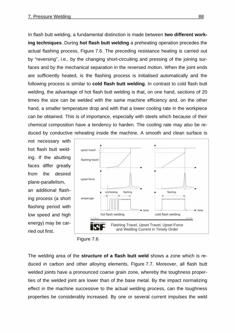
In flash butt welding, a fundamental distinction is made between two different work-
ing techniques. During hot flash butt welding a preheating operation precedes the
actual flashing process, Figure 7.6. The preceding resistance heating is carried out
by “reversing”, i.e., by the changing short-circuiting and pressing of the joining sur-
faces and by the mechanical separation in the reversed motion. When the joint ends
are sufficiently heated, is the flashing process is initialised automatically and the
following process is similar to cold flash butt welding. In contrast to cold flash butt
welding, the advantage of hot flash butt welding is that, on one hand, sections of 20
times the size can be welded with the same machine efficiency and, on the other
hand, a smaller temperature drop and with that a lower cooling rate in the workpiece
can be obtained. This is of importance, especially with steels which because of their
chemical composition have a tendency to harden. The cooling rate may also be re-
duced by conductive reheating inside the machine. A smooth and clean surface is
not necessary with
hot flash butt weld-
ing. If the abutting
faces differ greatly
from the desired
plane-parallelism,
an additional flash-
ing process (a short
flashing period with
low speed and high
energy) may be car-
ried out first.
The welding area of the structure of a flash butt weld shows a zone which is re-
duced in carbon and other alloying elements, Figure 7.7. Moreover, all flash butt
welded joints have a pronounced coarse grain zone, whereby the toughness proper-
ties of the welded joint are lower than of the base metal. By the impact normalizing
effect in the machine successive to the actual welding process, can the toughness
properties be considerably increased. By one or several current impulses the weld
Figure 7.6
Flashing Travel, Upset Travel, Upset Forceand Welding Current in Timely Order
br-er7-06e.cdr
hot flash welding cold flash welding
upset travel
flashing travel
upset force
amperage
time time
preheating flashing flashing

7. Pressure Welding 89
temperatures are increased by up to approximately 50° over the austeniting tempera-
ture of the metal.
Steels, aluminium, nickel and copper alloys can be welded economically with the
flash butt welding
process. Supported
by the axial force,
shrinkage in flash
butt welding is so
insignificant that
only very low resid-
ual stresses occur.
It is, therefore, pos-
sible to weld also
steels with a higher
carbon content.
Profiles of all kind are butt welded
with this method. The method is used
for large-scale manufacture and with
components of equal dimensions. The
weldable cross-sections may reach
dimensions of up to 120,000 mm².
Areas of application are the welding of
rails, the manufacture of car axles,
wheel rims and shafts, the welding of
chain links and also the manufacture
of tools and endless strips for pipe
production.
Friction welding is a pressure weld-
ing method where the necessary heat
for joining is produced by mechanical
friction. The friction is, as a rule, gen-
erated by a relative motion between a
Secondary StructureAlong a Flash Butt Weld
br-er7-07e.cdr
heat affected zone
10 mm
0,1 mm
material: C60 E
weld coarse grain zone fine grain zone soft-annealing zone base metal
Figure 7.7
© ISF 2002br-er7-08e.cdr
n
n
F friction force1
F upset force2
Figure 7.8

7. Pressure Welding 90
rotating and a stationary workpiece
while axial force is being applied at
the same time, Figure 7.8.
After the joint surfaces are adequately
heated, the relative motion is discon-
tinued and the friction force is in-
creased to upsetting force.
An even, lip-shaped bead is produced
which may be removed in the welding
machine by an additional accessory
unit. The bead is often considered as
the first quality criterion.
Figure 7.9 shows all phases of the
friction welding process. In most
cases this method is used for rota-
tion-symmetrical parts. It is, nowa-
days, also possible to accurately join
rectangular and polygonal cross-
sections.
The most common variant of friction
welding is friction welding with a con-
tinuous drive and friction welding with
a flywheel drive, Figure 7.10. In fric-
tion welding with continuous drive,
the clamped-on part to be joined is
kept at a constant nominal speed by a
drive, while the workpiece in the slid-
ing chuck is pressed with a defined
friction force. The nominal speed is
maintained until the demanded tem-
br-er7-09e_sw.cdr
Phases of Friction Welding Process
Figure 7.9
© ISF 2002br-er7-10e.cdr
conventional friction welding
clutch
driving motor
brakeclamping tool clamping tool
workpiece pressure elementfor axial pressure
flywheel friction welding
clamping tool clamping tool
workpiecepressure elementfor axial pressure
flywheel
Figure 7.10

7. Pressure Welding 91
perature profile has been achieved. Then the motor is declutched and the relative
motion is neutralised by external braking. In general, the friction force is raised to up-
setting force after the rotation movement has been discontinued. During flywheel
friction welding, the inertia mass is raised to nominal speed, the drive motor is de-
clutched and the stationary workpiece is, with a defined axial force, pressed against
the rotating workpiece. Welding is finished when the total kinetic energy - stored in
the flywheel – has been consumed by the friction processes. This is the so-called
self-breaking effect of the system. The method is used when, based on metallurgical
processes, extremely short welding times may be realised. Further process variants
are radial friction welding, orbital friction welding, oscillation friction welding and fric-
tion surfacing.
However, these
process variants
are until today still
in the experimental
stage. Recently,
new developments
in the field of friction
stud welding –
studs on plates –
have been intro-
duced.
Figure 7.11 depicts the variation in time of the most important process parame-
ters in friction welding with continuous drive and flywheel friction welding. The occur-
ing moments’ maxima may be interpreted as follows: The first maximum, at the start
of the frictional contact, is explained by the formation of local fusion zones and their
shearing off in the lower temperature range.
The torque decreases as a result of the risen temperature - which again is a conse-
quence of the increased plasticity - and of the lowered deformation resistance. The
second maximum is generated during the braking phase which precedes the spindle
standstill. The second maximum is explained by the increased deformation resis-
tance at dropping temperatures. The temperature drop in the joining zone is ex-
Comparison of the Welding Processes forConventional and Flywheel Friction Welding
br-er7-11e.cdr
conventional friction welding flywheel friction welding
number ofrevolutions
axialpressure
torque
20...100 Nmm-2
40...280
Nmm-2
time
friction welding time1...100s
friction welding time0,125...2s
braking0,1...0,5s
1800...
5400 min-1
900...
5400min-1
40...280
Nmm-2
Figure 7.11

7. Pressure Welding 92
plained by the lowered energy input – due to the rotation-speed decrease – and
also by the augmented radial displacement of the highly heated material into the weld
upset.
In friction welding
with a continuous
drive, the process
variation “com-
bined friction
welding” allows
the free and inde-
pendent from each
other selection of
the braking and
upsetting mo-
ments, Fig. 7.12.
In this case, the rotation-energy which has been stored in the drive motor, the spin-
dle and also in the clamping chuck, may be totally or partially converted by self-
breaking. Here, the breaking phase matches the breaking phase in flywheel welding.
The use of this process variant allows the welding structures to influence each other
in a positive way when many welding tasks are to be carried out. Moreover, the
torque range may
be accurately pre-
determined by the
microcontroller of
the braking initiator
which prevents the
slip-through of the
workpieces in the
clamping chuck.
The universal fric-
tion welding ma-
© ISF 2002
Combined Friction Welding
br-er7-12e.cdr
time
number of revolutions
friction force
reduction
upset force
Figure 7.12
© ISF 2002
Types of Friction Welding Processes
br-er7-13e.cdr
a) b)
c) d)
e) f)
P
P
P P
P
P
PP
P
Figure 7.13
7. Pressure Welding 93
chine is in its structure similar to a turning lathe, however, for the transmission of the
high axial forces, the machine structure must be considerably more rigid.
Basically, there are three types of friction welding: a) friction welding with a rotating
workpiece and a translational motion of the other workpiece; b) friction welding with
rotation and translational motion of one workpiece facing a stationary other work-
piece, c) rotation and translation of two workpieces against a stationary intermediate
piece. The remaining variations, shown in Figure 7.13, also find applications when
both workpieces have to rotate in opposite direction to each other. For example,
when a low diameter and, in connection with this, the low relative speeds demand the
necessary heat quantity.
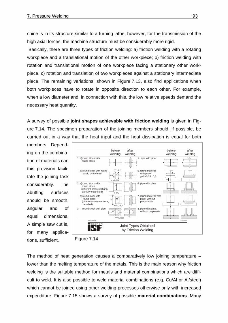
A survey of possible joint shapes achievable with friction welding is given in Fig-
ure 7.14. The specimen preparation of the joining members should, if possible, be
carried out in a way that the heat input and the heat dissipation is equal for both
members. Depend-
ing on the combina-
tion of materials can
this provision facili-
tate the joining task
considerably. The
abutting surfaces
should be smooth,
angular and of
equal dimensions.
A simple saw cut is,
for many applica-
tions, sufficient.
The method of heat generation causes a comparatively low joining temperature –
lower than the melting temperature of the metals. This is the main reason why friction
welding is the suitable method for metals and material combinations which are diffi-
cult to weld. It is also possible to weld material combinations (e.g. Cu/Al or Al/steel)
which cannot be joined using other welding processes otherwise only with increased
expenditure. Figure 7.15 shows a survey of possible material combinations. Many
© ISF 2002
Joint Types Obtainedby Friction Welding
br-er7-14e.cdr
beforewelding
afterwelding
beforewelding
afterwelding
8. pipe with plate, without preparation
7. round material with plate, without preparation
6. pipe with plate
5. round material with plate
g/d 0,25...0,3»
4. pipe with pipe1. a)round stock with round stock
b) round stock with round stock, chamfered
2. a)round stock with round stock (different cross-sections, partially machined)
b) round stock with round stock (different cross-sections, bevelled)
3. round stock with piped=0,75D
dD
0,75d
dd D
d 0,6D»
1..2°
(1/6)d
d
g
Figure 7.14

7. Pressure Welding 94
Secondary StructureAlong a Friction Weld
br-er7-16e.cdr
10 µm
1 mm
10 mm
metal: S235JRp = 30 N/mmt = 6 st = 250 N/mmn = 1500 U/min
2
2
St
structures on parallels with a 5 mm distance from the sample axis
base metal heat affected zone transition heat affected zone - weld metal
weld metal
Figure 7.16
combinations have, however, not yet been tested on their suitability to friction weld-
ing. Metallurgical reasons which may reduce the friction weldability are:
1. the quantity and distribution of
non-metal inclusions,
2. formation of low-melting or in-
termetallic phases,
3. embrittlement by gas absorp-
tion (as a rule, the costly, inert
gas shielding can be dis-
pensed with, even when weld-
ing titanium),
4. softening of hardened or pre-
cipitataly-hardened materials
and
5. hardening caused by too high
a cooling rate.
By the adjustment of the welding pa-
rameters in respect toweld joints, can
in most cases joints with good mechano-technological properties be obtained.
The secondary structure along the friction-welded joint is depicted in Figure 7.16. An
extremely fine-
grained structure
(forge structure)
develops in the join-
ing zone region.
This structure which
is typical of a fric-
tion-welded joint is
characterised by
high strength and
toughness proper-
ties.
© ISF 2002br-er7-15e.cdr
aluminiumaluminium alloysaluminium, sinteredleadcast iron (GGG, GT)hard metal, sinteredcobaltcoppermagnesiumbrassmolybdenumnickelnickel alloysniobiumsilversteel, unalloyedsteel, alloyed steel, high alloyedsteel, austenticcast steelfree cutting steelstellitetantalumtitaniumvanadiumtungstencirkon
cirk
ontu
ngst
enva
nadi
umtit
aniu
mta
ntal
umst
ellit
efr
ee c
uttin
g st
eel
cast
ste
elst
eel,
aust
entic
stee
l, hi
gh a
lloye
dst
eel,
allo
yed
stee
l, un
allo
yed
silv
erni
obiu
mni
ckel
allo
ysni
ckel
mol
ybde
num
bras
sm
agne
sium
copp
erco
balt
hard
met
al, s
inte
red
cast
iron
(GG
G, G
T)
lead
alum
iniu
m, s
inte
red
alum
iniu
m a
lloys
alum
iniu
m
friction weldable
restricted friction weldable
not friction weldable
not tested
Figure 7.15
7. Pressure Welding 95
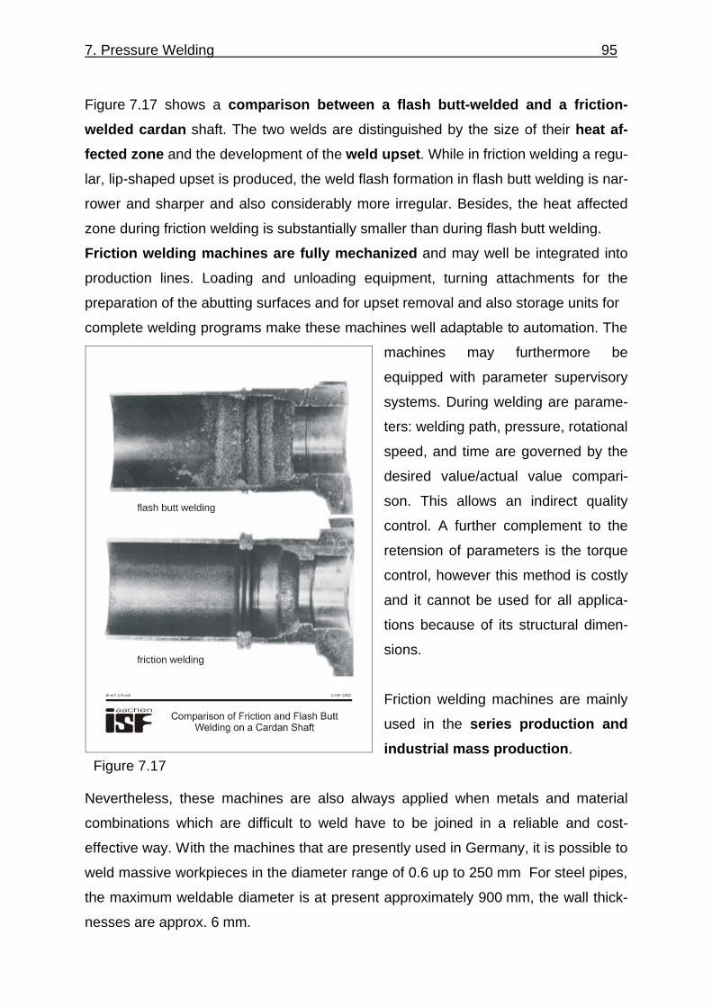
Figure 7.17 shows a comparison between a flash butt-welded and a friction-
welded cardan shaft. The two welds are distinguished by the size of their heat af-
fected zone and the development of the weld upset. While in friction welding a regu-
lar, lip-shaped upset is produced, the weld flash formation in flash butt welding is nar-
rower and sharper and also considerably more irregular. Besides, the heat affected
zone during friction welding is substantially smaller than during flash butt welding.
Friction welding machines are fully mechanized and may well be integrated into
production lines. Loading and unloading equipment, turning attachments for the
preparation of the abutting surfaces and for upset removal and also storage units for
complete welding programs make these machines well adaptable to automation. The
machines may furthermore be
equipped with parameter supervisory
systems. During welding are parame-
ters: welding path, pressure, rotational
speed, and time are governed by the
desired value/actual value compari-
son. This allows an indirect quality
control. A further complement to the
retension of parameters is the torque
control, however this method is costly
and it cannot be used for all applica-
tions because of its structural dimen-
sions.
Friction welding machines are mainly
used in the series production and
industrial mass production.
Nevertheless, these machines are also always applied when metals and material
combinations which are difficult to weld have to be joined in a reliable and cost-
effective way. With the machines that are presently used in Germany, it is possible to
weld massive workpieces in the diameter range of 0.6 up to 250 mm For steel pipes,
the maximum weldable diameter is at present approximately 900 mm, the wall thick-
nesses are approx. 6 mm.
© ISF 2002br-er7-17e.cdr
flash butt welding
friction welding
Figure 7.17
7. Pressure Welding 96
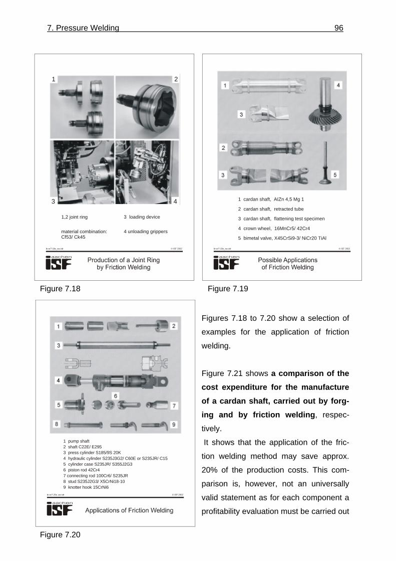
Figures 7.18 to 7.20 show a selection of
examples for the application of friction
welding.
Figure 7.21 shows a comparison of the
cost expenditure for the manufacture
of a cardan shaft, carried out by forg-
ing and by friction welding, respec-
tively.
It shows that the application of the fric-
tion welding method may save approx.
20% of the production costs. This com-
parison is, however, not an universally
valid statement as for each component a
profitability evaluation must be carried out
© ISF 2002br-er7-18e_sw.cdr
1 2
3 4
1,2 joint ring 3 loading device
4 unloading grippersmaterial combination:Cf53/ Ck45
© ISF 2002br-er7-19e_sw.cdr
1 cardan shaft, AIZn 4,5 Mg 1
2 cardan shaft, retracted tube
3 cardan shaft, flattening test specimen
4 crown wheel, 16MnCr5/ 42Cr4
5 bimetal valve, X45CrSi9-3/ NiCr20 TiAl
Figure 7.18 Figure 7.19
© ISF 2002br-er7-20e_sw.cdr
1 pump shaft2 shaft C22E/ E2953 press cylinder S185/9S 20K4 hydraulic cylinder S235J3G2/ C60E or S235JR/ C155 cylinder case S235JR/ S355J2G36 piston rod 42Cr47 connecting rod 100Cr6/ S235JR8 stud S235J2G3/ X5CrNi18-109 knotter hook 15CrNi6
Figure 7.20

7. Pressure Welding 97
separately. The comparison is just to show that, in many applications, considerable
savings can be made if the matter of the joining technology by “friction welding” could
be circulated to a wider audience of design and production engineers.
Figure 7.22 shows
in brief the impor-
tant advantages
and disadvan-
tages of friction
welding in com-
parison with the
competitive
method of flash
butt welding.
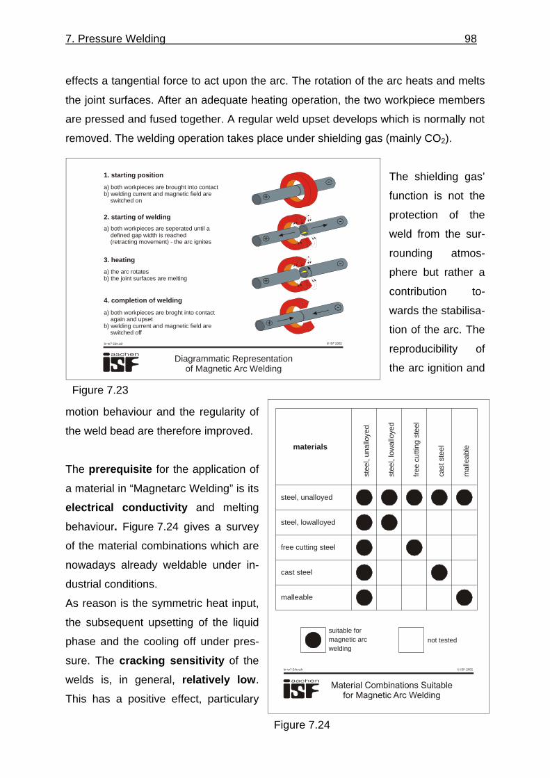
Pressure welding with magnetically
impelled arc, “Magnetarc Welding”,
is an arc pressure welding method for
the joining of closed structural tu-
bular shapes, Figure 7.23. The weld-
able wall thickness range is between
0.7 and 5 mm, the weldable diameter
range between 5 and 300 mm. In
“Magnetarc Welding” an arc burns be-
tween the joining surfaces and is ro-
tated by external magnetic forces. This
is achieved by a magnet coil system
that produces a magnetic field.
The combined action of this magnetic
field and the arc’s own magnetic field
Cost Comparison of Forging/ FrictionWelding in a Case of a Cardan Shaft
br-er7-21e.cdr
forged piece
motor shaft € 20,-
€ 20,-
friction-welded piece
material costs shaftØ30 und 40 mm
€
€
€
€
7,50
4,25
3,-
14,75
2x friction weldsincl. upset removal
flange,forged
160
mm
Ø40
mm
Ø30 mm
friction welds
940 mm
Figure 7.21
© ISF 2002br-er7-22e.cdr
Advantages and disadvantages of friction weldingin comparison with the competitive flash butt welding
advantages:
disadvantages:
- clean and well controllable bulging- low heat influence on joining members- better control of heat input- low phase seperation phenomena in the bond zone- hot forming causes permanent recovery and recrystallisation processes in the welding area thus forming a very fine-grained structure with good toughness and strength properties (forged structure)- low susceptibility to defects, extremely good reproducibility within a wide parameter range- frequently shorter welding times- more choice in the selection of weldable materials and material combinations
- torque-safe clamping necessary- machine-determined smaller maximum weldable cross-sections- susceptibility to non-metal inclusions- high expenditure requested because of high manufacturing tolerances- high capital investment for the machine
Figure 7.22
7. Pressure Welding 98
effects a tangential force to act upon the arc. The rotation of the arc heats and melts
the joint surfaces. After an adequate heating operation, the two workpiece members
are pressed and fused together. A regular weld upset develops which is normally not
removed. The welding operation takes place under shielding gas (mainly CO2).
The shielding gas’
function is not the
protection of the
weld from the sur-
rounding atmos-
phere but rather a
contribution to-
wards the stabilisa-
tion of the arc. The
reproducibility of
the arc ignition and
motion behaviour and the regularity of
the weld bead are therefore improved.
The prerequisite for the application of
a material in “Magnetarc Welding” is its
electrical conductivity and melting
behaviour. Figure 7.24 gives a survey
of the material combinations which are
nowadays already weldable under in-
dustrial conditions.
As reason is the symmetric heat input,
the subsequent upsetting of the liquid
phase and the cooling off under pres-
sure. The cracking sensitivity of the
welds is, in general, relatively low.
This has a positive effect, particulary
Diagrammatic Representationof Magnetic Arc Welding
br-er7-23e.cdr
1. starting position
2. starting of welding
3. heating
4. completion of welding
a) both workpieces are brought into contactb) welding current and magnetic field are switched on
a) both workpieces are seperated until a defined gap width is reached (retracting movement) - the arc ignites
a) the arc rotatesb) the joint surfaces are melting
a) both workpieces are broght into contact again and upsetb) welding current and magnetic field are switched off
Figure 7.23
© ISF 2002br-er7-24e.cdr
steel, unalloyed
steel, lowalloyed
free cutting steel
cast steel
malleable
stee
l, un
allo
yed
stee
l, lo
wal
loye
d
free
cut
ting
stee
l
cast
ste
el
mal
leab
lematerials
suitable formagnetic arcwelding
not tested
Figure 7.24

7. Pressure Welding 99
when steels with a high carbon content or machining steels are welded. The joining
faces of the workpieces must be free from contamination, such as rust or scale.
To obtain a defect-free weld, normally a simple saw cut is a sufficient preparation of
the abutting sur-
faces. If special
demands are put
on the dimensional
accuracy of the
joints, the prefabri-
cation tolerances
have to be ad-
justed accordingly.
This applies also to
friction welding.
Figures 7.25 and 7.26 show several
application examples of pressure
welding with magnetically impelled arc.
Figure 7.27 shows a summary of the
most important advantages and dis-
advantages of this method in com-
parison with the competitive methods
of friction welding and flash butt weld-
ing.
In friction-stir welding a cylindrical,
mandrel-like tool carries out rotating
self-movements between two plates
which are knocked and clamped onto
a fixed backing. The resulting friction
heat softens the base metal, although
© ISF 2002
Applications for Magnetic Arc Welding
br-er7-25e_sw.cdr
Figure 7.25
© ISF 2002br-er7-26e_sw.cdr
Figure 7.26
7. Pressure Welding 100
the melting point is not reached. The
plastified material is displaced by the
mandrel and transported behind the
tool where a longitudinal seam devel-
ops.
The advantages of this method which
is mainly used for welding of alumin-
ium alloys is the low thermal stress of
the component which allows joining
with a minimum of distortion and
shrinkage. Welding fumes do not de-
velop and the addition of filler metal or
shielding gases is not required.
© ISF 2002br-er7-27e.cdr
Advantages and disadvantages of magnetic arc welding incomparison with flash butt welding and/ or friction welding
advantages:
- lower energy demands
- material savings through lower loss of length
- better dimensional accuracy in joining especially for small
wall thicknesses
- in comparison with friction welding less moving parts
(only axial movement of one joining member during upsetting)
- no restrictions to the free clamping length
- smaller and more regular welding edge
- no spatter formation
disadvantages:
- suitable for small wall thicknesses only
(maximum wall thickness: 4 - 5 mm)
- welding parameters must be kept within narrow limits
- only magnetizing steels are weldable without any difficulties
Figure 7.27
Friction-Stir Welding
br-er7-28e.cdr
tool collar
fixed backing
contoured pin
workpiece
Figure 7.28