630 mtx chokes - audio systems group, inc. home page
TRANSCRIPT

Don’t Bother Taking Notes – These slides will be on my
website next week
k9yc.com/publish.htm

Acknowledgement
Thanks to Wayne Burdick, N6KR, Elecraft co-owner, who provided the ferrite cores used for this work, and for work on chokes and transformers for receiving antennas

Common Mode vs Differential Mode• Differential mode current is the normal
transmission of power inside the coax, or between paired conductors
• Common mode current is carried on the outside of the coax shield, or as the difference of unequal currents on the two conductors of 2-wire line

Why Common Mode Current is Bad• When common mode current flows, the
feedline becomes part of the antenna• If the antenna is not perfectly balanced
(few are), common mode current flows putting RF in the shack and coupling local RF noise to the antenna
• Common mode current radiates– Into your living room (and your
neighbor’s)• Antennas receive like they radiate
–Noise from you and your neighbors

Choking Impedance• Ferrite chokes work by adding a large
impedance in series with the common-mode circuit
• We achieve high values of common mode impedance by winding multiple turns of a transmission line onto a suitable ferrite core to form a parallel resonant circuit at the frequency(ies) where we want to use the choke

Equivalent Circuit of a Ferrite Choke
Low Frequencies Mid-Frequencies
__ __Near Resonance

More General Equivalent Circuit
__ __
Including Dimensional Resonance
(more about that later)

We’ll Use This Physical Equivalent Circuit to Understand the Choke
__ __Data Sheets Use This Equivalent Circuit to Graph the Impedance

Rs and Xs Are What We Can Measure
__ __
We can use a graph of Rs and Xs values to compute Lp, Rp, and Xp
__ __

Rs and Xs• Ls and Rs are the inductance and loss
(resistance) coupled from the core• Ls and Rs are multiplied by the N2 (the
number of turns through the core) • Cp is the total stray capacitance
between turns, and between the turns and the core
• As we wind turns, the resonance moves down in frequency and the choking impedance increases

Tuning the Choke• We put the resonance where we want
our choke to work well by varying the number of turns and by choosing the “right” ferrite mix
• A “right” ferrite mix is lossy at frequencies where we want the choke to work
• The “right” ferrite mix for 630M is Fair-Rite #75

Rs and Xs• ZMAG = sqrt [(Rs)2 + (Xs)2]• Z = Rs + j Xs• We measure ZMAG, Rs, and Xs • Or, more precisely, we place the choke
in series between a 50Ω generator and 50Ω voltmeter, forming a voltage divider
• The generator and voltmeter take the form of a Vector Network Analyzer– VNWA3EC, designed by German EE prof
DG8SAQ, sold by SDR Kits in the UK

Measuring Coax Chokes
____ __
Swept RFGenerator RF Voltmeter
Choke 50Ω
50Ω
____
__
Rs, Xs, Rp, Cp, Lp• Rp, Cp, and Lp are approximately
constant with frequency – They describe the physical properties of
the choke
• Rs and Xs have different values for every frequency
• At resonance, Rs = Rp• Lp is the inductance we would
measure far below resonance• Cp is the value that resonates with Lp

Rs and Xs• We measure S21 (the voltage divider
ratio) and solve the voltage divider equation backwards to find Z of the choke
• The control software for the VNWA does the math and plots the data you will see later
• S21 is the blue curve in the plots of choking impedance

Choking Z RG400 18 Turns
Z mag
RsRs
5kΩ
Xs
2.5kΩ
Z mag
Rs630M
Xs=0
Log Frequency
100 kHz 1 MHz 10 MHz
S21

Why Choking Resistance (Rs) Matters• The common mode circuit includes the
antenna, the feedline, and whatever the feedline is connected to (usually ground via the transmitter)
• The antenna, feedline, and connection at the far end have some impedance by virtue of their combined electrical length
• That impedance can be inductive or capacitive at any given frequency
Why Choking Resistance (Rs) Matters• That impedance can be inductive or
capacitive at any given frequency • When it is inductive, the inductance of
an inductive choke adds to it, and common mode current is reduced
• When it is capacitive, it cancels the inductance of an inductive choke, leaving only the resistance of the choke, Rs to reduce the current
• A choke with a high value of Rs works independent of feedline length

Using Transmitting Chokes• Most 630m antennas are (very short)
verticals working against some form of counterpoise or radial system
• One or more chokes at the feedpoint prevents the feedline (and house wiring) from becoming part of the counterpoise or radial system

630m Power Requirements• We can run 5w EIRP on the 630m band
• EIRP = Xmtr Power x Antenna Efficiency
• Because any antenna/counterpoise/radial system we can build will be very short as a fraction of a wavelength, 630m antennas are very inefficient, so:
• Efficiencies of 1% - 10% are common
• This corresponds to 50 – 500W transmitter power to radiate 5W
• A choke with Rs = 5kΩ should handle 500W
• Rs = 2.75KΩ should handle 250W
Good Stuff On 630M Antennas
• antennasbyn6lf.com• Rudy Severns, N6LF has done lots of
great work on antennas and radial systems for the low bands– He’s shown how to compute efficiency for
real world 630M antennas
• It’s all on his website• He’s an ARRL Hanbook and Antenna
Book contributor
Power Handling and Choking Impedance
• Power in the choke is I2R where I is the common mode current and R is the choking resistance, Rs
• Common mode current is E/(Rs), where E is the common mode voltage
• We want the choke to reduce common mode current to near zero
• Because power is current squared, the power falls with increasing Rs

Winding the Chokes• When counting turns, count the
number of times the cable passes through the inside of the toroid
• Turns must be wound sequentially, and conductors must not be twisted– A twisted or reversed order turn cancels
another turn, reduces choking impedance
• 17-18 turns of RG400 or pairs of #12/2 Teflon, NM, or THHN fill a 2.4” i.d. core
• It is OK for one end of the winding to overlap the other end to fit more turns
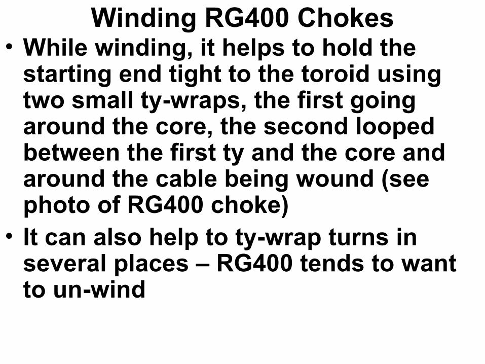
Winding RG400 Chokes• While winding, it helps to hold the
starting end tight to the toroid using two small ty-wraps, the first going around the core, the second looped between the first ty and the core and around the cable being wound (see photo of RG400 choke)
• It can also help to ty-wrap turns in several places – RG400 tends to want to un-wind

18 Turns RG400 on Fair-Rite #75 2.4-in o.d. Toroid

Winding Teflon Chokes• It’s also a good idea to tywrap the start
of Teflon windings – the teflon wire is slippery
• When cutting the coax or wire, allow 3.75-in per turn, plus whatever lead length is needed for termination to antenna and feedline
• Winding with different colors makes it easier to spot twists and reverse order turns
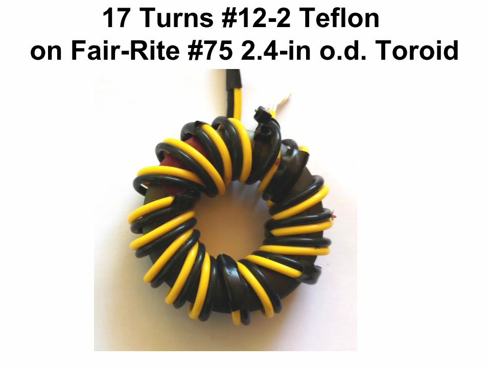
17 Turns #12-2 Teflon on Fair-Rite #75 2.4-in o.d. Toroid
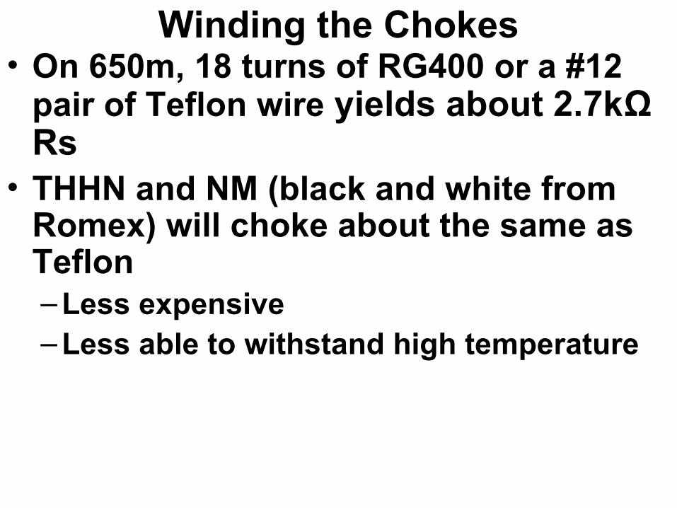
Winding the Chokes• On 650m, 18 turns of RG400 or a #12
pair of Teflon wire yields about 2.7kΩ Rs
• THHN and NM (black and white from Romex) will choke about the same as Teflon– Less expensive– Less able to withstand high temperature
Recommendations• A single 18-turn choke will handle
200W
• For maximum suppression and greater power handling, use two 18-turn chokes wired in series
• Chokes wound on #31 cores can be added in series to use the same antenna to cover higher frequency bands
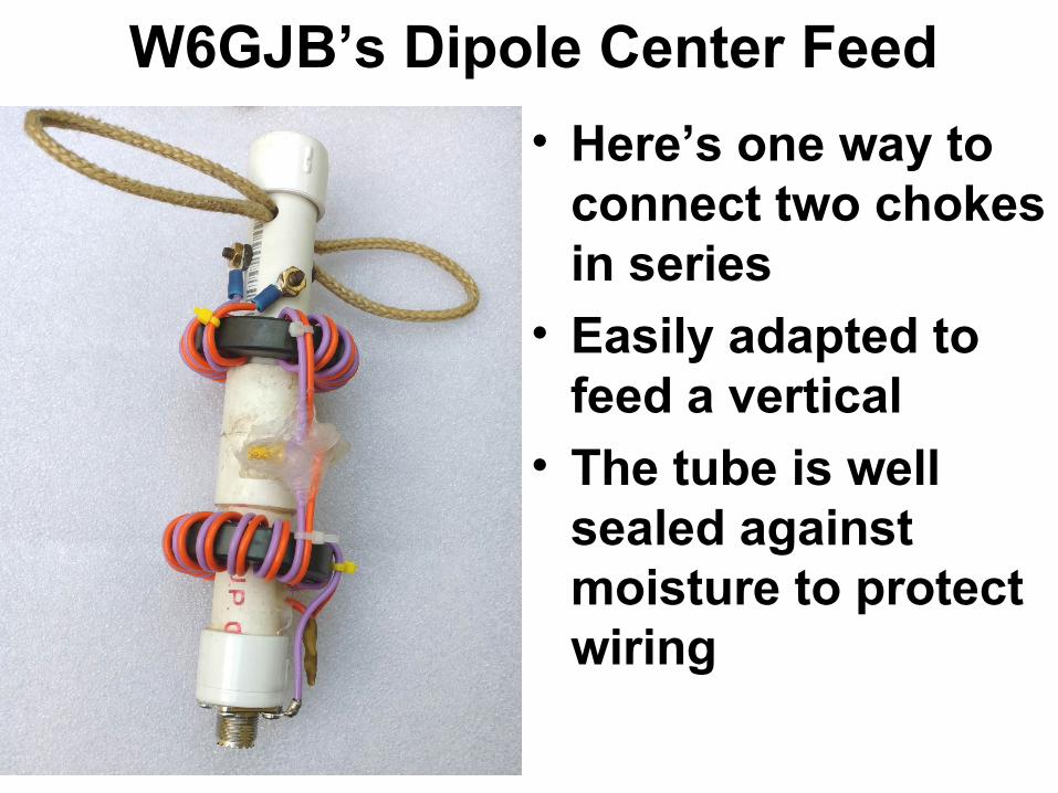
W6GJB’s Dipole Center Feed
• Here’s one way to connect two chokes in series
• Easily adapted to feed a vertical
• The tube is well sealed against moisture to protect wiring

The Wire• RG400 is 50Ω Zo, the size of RG58
–Stranded silver-coated copper center–Two silver-coated copper braid shields–Teflon dielectric and outer jacket
• The paired windings (Teflon, THHN, NM) form a transmission line with Zo near 100Ω
• The length of wire in two chokes is so short (about 0.005λ) that any mismatch to an antenna doesn’t matter

Why RG400 and not RG142?• The center conductor of
–RG400 is stranded silver-coated copper–RG142 is silver-coated copper-clad
solid steel• Their shields are the same – double
shields, each silver-coated copper braid
• RG400 center is more flexible, less likely to migrate close to the shield when wound tightly around the ferrite core

Enameled Wire Works Too• Zo is near 50Ω• Fair-Rite #75 material is optimum for
630m, but is also a good conductor
• Enameled wire is easy scraped, can short to the core, which defeats the choke
• Cores wound with enameled wire should have a wrap of tape to insulate the wire from the core

Buying The Cores• Fair-Rite part number 5975003801
–$7.50 at Kreger Components (1-49 qty)–$11.08 at Mouser (1-9 qty), $9.23 (10 qty)–$10 at Digikey (1-9 qty), $8.50 (10 qty)–These are industrial vendors, with good
discounts for quantity
–Buy larger quantities when you can–Arrow is good for Fair-Rite that they
stock, but don’t stock this one

Don’t Buy Ferrites From Ham Vendors• They have invented their own part
numbers (FT240, for example) so you don’t know what to order from industrial vendors, who offer great discounts for quantity–Amidon–Palomar
• This allows them to sell at very high markups

Some Good Vendors• Arrow Electronics
• Lodestone Pacific
• Dexter Magnetics• Krieger Components
• Newark
• Allied
• Digikey
• Mouser

Buying Cores• Not everyone stocks everything
• Call around – most will be cheaper for what they have in stock, and that can vary
• Build quantity by combining an order with other hams

Buying The Coax• I buy Harbor Industries RG400 on ebay
–$230 for 100ft –Others sell shorter lengths

Buying The Wire• Buy #12 stranded, silver coated copper
Teflon on ebay (new, surplus)–$12 for 20 ft from seller parelectronics–He has multiple colors
• Buy THHN or Romex at the big box store–Solid winds better than stranded

Buying Enameled Wire• I found very good enameled wire from
Temco on ebay (their brand, new) –Sold by weight–10 lb (315 ft) AWG #10 for $102–#12 is good enough, costs less–Shorter lengths are available
• Pay attention to voltage breakdown rating of what you’re buying– That’s why I bought Temco – specs are on
their website

Choking Z RG400 18 Turns
Z mag
RsRs
5kΩ
Xs
2.5kΩ
Z mag
Rs630M
Xs=0
Log Frequency
100 kHz 1 MHz 10 MHz

Choking Z Teflon #12/2 18 Turns
5kΩ
2.5kΩ
100 kHz
Xs
Z mag
Rs
630M
Log Frequency
1 MHz
Xs=0
10 MHz
What About #77 Core Palomar Sells?• #77 and #78 are almost the same• I have some #78 cores, but not #77
• So I measured #78
• It’s a terrible choice for any ham bands!
• #77 has the same problem
• Fair-Rite does not advise using 77 or 78 for chokes – they are inductive parts– Used in power circuits in the 20-100 kHz
range
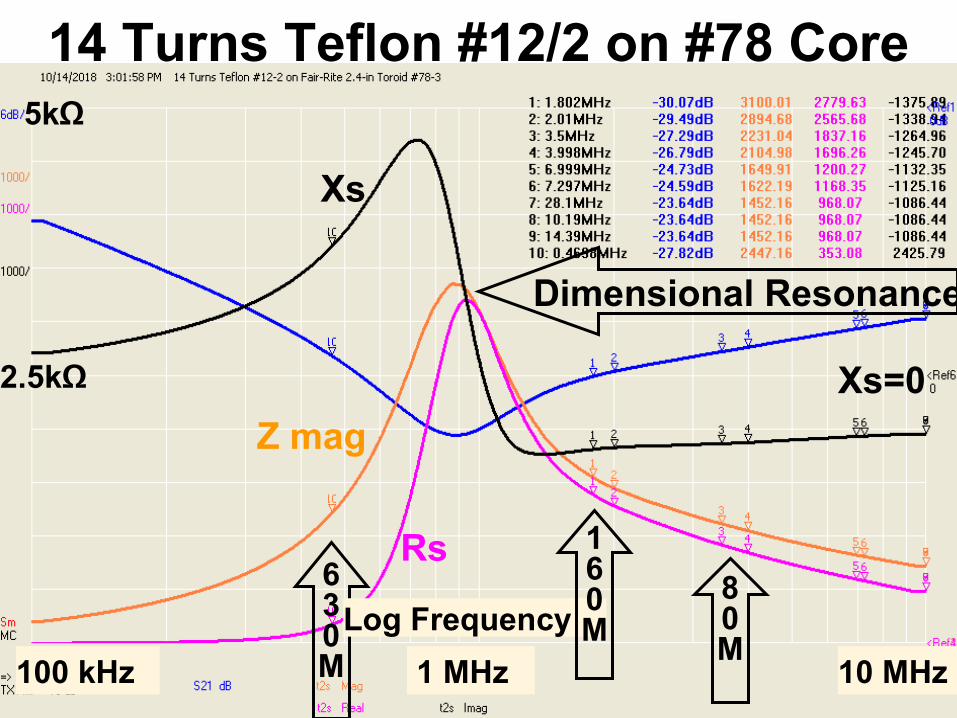
14 Turns Teflon #12/2 on #78 Core5kΩ
Xs
2.5kΩ
Z mag
Rs
100 kHz
630M
Log Frequency
1 MHz
Xs=0
10 MHz
Dimensional Resonance
160M
80M
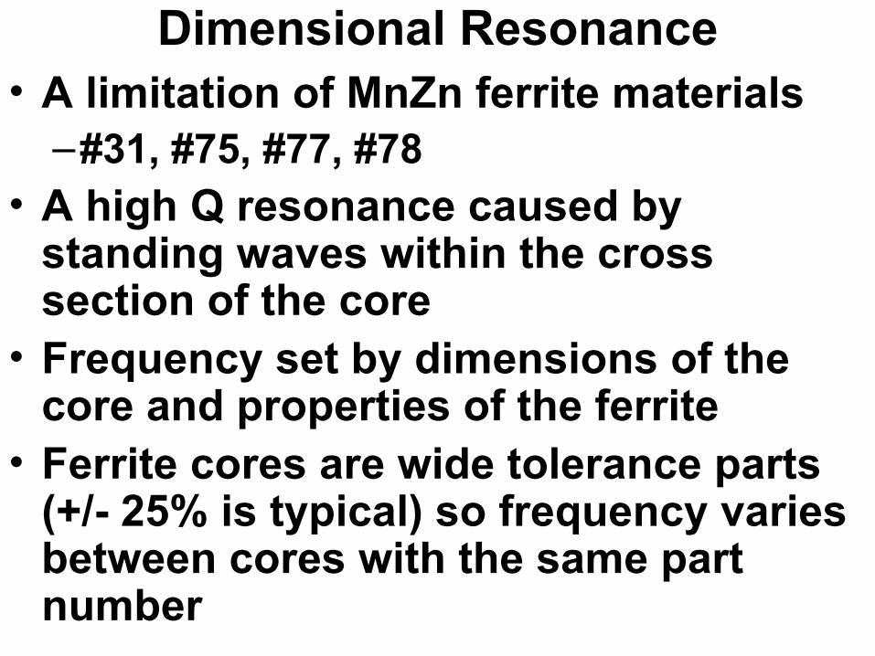
Dimensional Resonance• A limitation of MnZn ferrite materials
–#31, #75, #77, #78• A high Q resonance caused by
standing waves within the cross section of the core
• Frequency set by dimensions of the core and properties of the ferrite
• Ferrite cores are wide tolerance parts (+/- 25% is typical) so frequency varies between cores with the same part number

Dimensional Resonance Is Why:• #75 is good for 630M but not below
about 300 kHz• #31 is good for 160M-6M, but not below
160M
• #77 and #78 (almost the same) are not good for chokes at all
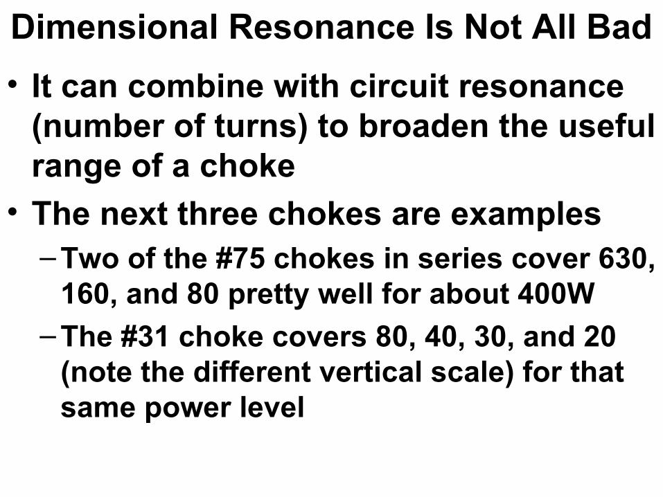
Dimensional Resonance Is Not All Bad
• It can combine with circuit resonance (number of turns) to broaden the useful range of a choke
• The next three chokes are examples– Two of the #75 chokes in series cover 630,
160, and 80 pretty well for about 400W
– The #31 choke covers 80, 40, 30, and 20 (note the different vertical scale) for that same power level

Choking Z RG400 17 Turns
100 kHz 1 MHz 10 MHz
Log Frequency
630M
2.5kΩ
5kΩ
Z mag
Rs
Xs
Xs=0Z mag
Rs
Z mag
Rs

Choking Z Teflon #12/2 18 Turns
5kΩ
2.5kΩ
100 kHz
Xs
Z mag
Rs
630M
Log Frequency
1 MHz
Xs=0
10 MHz

14 Turns Teflon on #31 Toroid
Log Frequency
Z mag
Rs
Xs
Xs=0
80M
40M
30M
20M
160M
1 MHz 10 MHz 30 MHz
6.25kΩ
12.5kΩ
Log Frequency
80M
160M
Note different vertical scale

Winding More Turns On Second Layer• Choking Z can be increased by adding
turns on a second layer• Increased capacitance moves
resonance down, sacrificing higher bands
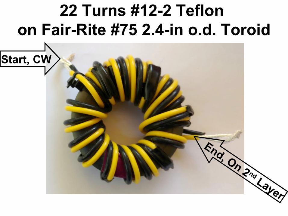
22 Turns #12-2 Teflon on Fair-Rite #75 2.4-in o.d. Toroid
Start, CW
End, On 2 nd Layer

Winding More Turns On Second Layer• For this 22 turn choke (5 turns
overlapped) – Choking Z ~ 4.5kΩ 0n 630M
– Almost doubles choking Z with a single core
– Added turns excite dimensional resonance around 300 kHz

Choking Z Teflon #12/2 22 Turns
100 kHz
Log Frequency
1 MHz 10 MHz
630M
2.5kΩ
Z mag
Xs=0
5kΩ
XsRs
Dimensional Resonance
Be Careful About Taking This Too Far
• Component tolerances (+/- 25%) can vary frequency of dimensional resonance, moving it too far from 630M
• Two chokes with fewer turns may be a safer choice

K9YC’s BS Filter• Some vendors who don’t understand
chokes are selling hams the wrong materials, and at crazy markups
• Palomar got a spot at Visalia to give hams wrong advice (to sell hams the wrong stuff)
• I couldn’t get on the program!
Fair-Rite Toroids For Chokes• #43 is useless below about 10 MHz
• #61 is useless below VHF
• Dimensional resonance makes–#31 useless below about 1.5 MHz–#77 and #78 almost useless on any
band for multi-turn chokes–#75 useless below about 400 kHz
• Palomar is selling #77 and #61 for chokes

Ferrites Have Multiple Uses• Nearly all ferrite materials have low
loss at low frequencies, and a lot of loss at high frequencies
• “Low” and “high” depends on the ferrite chemical mix (the number)
• Fair-Rite, a US company with factories in the US and in China, manufactures virtually all ferrite cores used by hams

Range of Commonly Used Ham FerritesFerrite
MixLow Loss
(Power, Xfmrs)High Loss (Chokes)
#31 Not useful 1.5 – 150 MHz#43 Not useful 12 – 300 MHz#61 Good to 15 MHz
OK to 30 MHz200 MHz – 2 GHz
#67 Good to 50 MHz Not useful#75 Below 100 kHz 0.4 – 20 MHz#77 Below 100 kHz Not useful#78 Below 200 kHz Not useful

Chokes Wound on Various Fair-Rite Core Materials
• #43 is a good choice above 10 MHz
• #31 is best for 160M – 30M, useful up to 6M
• #75 is best for 630M
• I haven’t yet found a good material for the 2200M (135 kHz band)