rexroth indramotion mtx · rexroth indramotion mtx plc interface r911322275 edition 01. rexroth...
TRANSCRIPT

Project Planning Manual
Electric Drivesand Controls Pneumatics Service
Linear Motion and Assembly TechnologiesHydraulics
Rexroth IndraMotion MTXPLC Interface
R911322275Edition 01
Rexroth IndraMotion MTXPLC Interface
Project Planning Manual
DOK-MTX***-PLC*INT*V08-PR01-EN-P
RS-b7e2d108aec467550a6846a00094ad4d-1-en-US-6
The manual describes the interface signals and the program modules for theintegrated PLC.
Edition Release Date Notes
120-2500-B362-01/EN 11.2007 First edition for 08VRS
© 2007 Bosch Rexroth AGCopying this document, giving it to others and the use or communication of thecontents thereof without express authority, are forbidden. Offenders are liablefor the payment of damages. All rights are reserved in the event of the grant ofa patent or the registration of a utility model or design (DIN 34-1).The specified data is for product description purposes only and may not bedeemed to be guaranteed unless expressly confirmed in the contract. All rightsare reserved with respect to the content of this documentation and the availa‐bility of the product.Bosch Rexroth AGBgm.-Dr.-Nebel-Str. 2 ■ 97816 Lohr a. Main, GermanyPhone +49 (0)93 52/ 40-0 ■ Fax +49 (0)93 52/ 40-48 85http://www.boschrexroth.com/Machine Tool System Development AB (BaWe/MePe)This document has been printed on chlorine-free bleached paper.
Title
Type of Documentation
Document Typecode
Internal File Reference
Purpose of Documentation
Record of Revision
Bosch Rexroth AG | Electric Drivesand Controls
Rexroth IndraMotion MTX | Project Planning Manual
Copyright
Validity
Published by
Note

Table of ContentsPage
1 Overview........................................................................................................................ 1
2 Important Instructions for Use........................................................................................ 52.1 Appropriate Use...................................................................................................................................... 52.1.1 Introduction.......................................................................................................................................... 52.1.2 Areas of Use and Application.............................................................................................................. 52.2 Inappropriate Use................................................................................................................................... 6
3 Safety Instructions for Electric Drives and Controls....................................................... 73.1 Safety Instructions - General Information............................................................................................... 73.1.1 Using the Safety Instructions and Passing them on to Others............................................................ 73.1.2 How to Employ the Safety Instructions................................................................................................ 73.1.3 Explanation of Warning Symbols and Degrees of Hazard Seriousness.............................................. 83.1.4 Hazards by Improper Use.................................................................................................................... 93.2 Instructions with Regard to Specific Dangers....................................................................................... 103.2.1 Protection Against Contact with Electrical Parts and Housings......................................................... 103.2.2 Protection Against Electric Shock by Protective Extra-Low Voltage................................................. 113.2.3 Protection Against Dangerous Movements....................................................................................... 113.2.4 Protection Against Magnetic and Electromagnetic Fields During Operation and Mounting.............. 143.2.5 Protection Against Contact with Hot Parts......................................................................................... 143.2.6 Protection During Handling and Mounting......................................................................................... 143.2.7 Battery Safety.................................................................................................................................... 153.2.8 Protection Against Pressurized Systems........................................................................................... 15
4 Configurations.............................................................................................................. 174.1 Configuration of the PLC NC Bit Interface ........................................................................................... 174.1.1 General.............................................................................................................................................. 174.1.2 The General Interface........................................................................................................................ 174.1.3 The Channel Interface (Channel Interface)....................................................................................... 174.1.4 The Axis Interface.............................................................................................................................. 184.1.5 The Spindle Interface........................................................................................................................ 194.2 Configuration of the Local Inputs ......................................................................................................... 204.2.1 General.............................................................................................................................................. 204.2.2 M Keys............................................................................................................................................... 214.2.3 Digital Inputs of the IO Card (HS Input)............................................................................................. 224.2.4 Digital Outputs of the IO Card (HS Output)....................................................................................... 224.3 Profibus Configuration ......................................................................................................................... 234.3.1 General.............................................................................................................................................. 234.3.2 The Profibus Master.......................................................................................................................... 234.3.3 Importing Device Master Files........................................................................................................... 244.3.4 Configuration..................................................................................................................................... 254.3.5 Setting Addresses in a DP Slave....................................................................................................... 26
Project Planning Manual | Rexroth IndraMotion MTX Electric Drivesand Controls
| Bosch Rexroth AG I/X
Table of Contents

Page
5 Global Interface Signals............................................................................................... 295.1 Overview Global Interface Signals........................................................................................................ 295.1.1 General ............................................................................................................................................. 295.1.2 Overview Output Signals (PLC → NC)............................................................................................... 295.1.3 Overview Input Signals (NC → PLC).................................................................................................. 295.2 Signal Description................................................................................................................................. 305.2.1 Output Signals (PLC→ NC) ............................................................................................................... 30
System Reset qGen_Reset............................................................................................................ 30Edit Inhibit Function qGen_EditInhibit............................................................................................. 30Stroke Inhibit Function qGen_StrokeInhibit.................................................................................... 31Stroke Reserve Function qGen_StrokeReserv............................................................................... 31Stroke on Function qGen_StrokeRel.............................................................................................. 31Delete Error info qGen_DelErrInfo.................................................................................................. 32
5.2.2 Input Signals (NC → PLC) ................................................................................................................. 32Hardware Warning iGen_HardwareState....................................................................................... 32Stroke Intended Function iGen_StrokeIntend................................................................................. 33'Stroke Is Not Running' Function iGen_NoStroke........................................................................... 33
6 Channel-related Interface Signals................................................................................ 356.1 Overview on Channel-related Interface Signals................................................................................... 356.1.1 General.............................................................................................................................................. 356.1.2 Overview of Output Signals (PLC → NC) .......................................................................................... 356.1.3 Overview of Input Signals (PLC → NC).............................................................................................. 376.2 Signal Description................................................................................................................................. 396.2.1 Output Signals (PLC → NC) .............................................................................................................. 39
Selection of Operating Mode qCh_OpModeSel_00 ... 03............................................................... 39PLC Operating Mode qCh_OpModePlc.......................................................................................... 40Automatic Restart qCh_Restart...................................................................................................... 41NC Start qCh_NCStart.................................................................................................................... 41Transfer Lock Function qCh_TransferLock.................................................................................... 41Feed Hold Function Halt qCh_FeedHold........................................................................................ 41Feed Stop Function qCh_FeedStop............................................................................................... 41Automatic Reselection from qCh_ReSelOff.................................................................................... 42Reset qCh_CtrlReset...................................................................................................................... 42'Cancel Distance to Go' Function qCh_CancDist........................................................................... 43'Switching to Next Block' Function qCh_NextBlk............................................................................ 43'Return to Contour' Function qCh_RetCont.................................................................................... 44'Fast Retract' Function qCh_Retract............................................................................................... 44Asynchronous Subroutine 1 ... 8 qCh_ASub1 ... 8......................................................................... 44WCS Manual + qCh_JogPlusWcs and WCS Manual - qCh_JogMinusWcs................................... 45Handwheel Selection bit 0 qCh_HandwSelWcs_00 and Handwheel Selection Bit 1 qCh_Handw‐SelWcs_01...................................................................................................................................... 45Handwheel Direction qCh_HandwDirWcs...................................................................................... 45Handwheel Position qCh_HandwPosMode.................................................................................... 45'Block Skip' Function qCh_BlkSlash............................................................................................... 45Optional Stop qCh_OptStop........................................................................................................... 46
II/X Bosch Rexroth AG | Electric Drivesand Controls
Rexroth IndraMotion MTX | Project Planning Manual
Table of Contents

Page
Conditional Jump qCh_OptJump.................................................................................................... 46Reduced Rapid Traverse qCh_RedRap......................................................................................... 46Override 100% qCh_Override100.................................................................................................. 46Override Bit 0 ... Bit 15 qCh_Override_00 ... 15............................................................................. 47Customer Input 1 ... 8 qCh_Custom1 ... 8...................................................................................... 47Online Correction Enable qCh_OnlCorrWcs.................................................................................. 47Online Correction Direction qCh_OnlCorrWcsDir........................................................................... 47Reverse Mode................................................................................................................................ 47Path Motion Advance .................................................................................................................... 48Motion Path Reverse ..................................................................................................................... 48Terminate Coupling qCh_CoordCoupleOff..................................................................................... 48TTL Enable qCh_TangTRotRel...................................................................................................... 48Test Feed qCh_TestFeed............................................................................................................... 48Test Rapid Traverse qCh_TestRap................................................................................................ 49
6.2.2 Input Signals (NC → PLC) ................................................................................................................. 49Active Operating Mode iCh_OpMode_00 ... 03.............................................................................. 49Test Mode iCh_DryRun.................................................................................................................. 50NC Ready iCh_NCReady............................................................................................................... 50Program Running iCh_ProgRun..................................................................................................... 51Transfer Lock Active iCh_TransferLockAct.................................................................................... 51Feed Hold Active iCh_FeedHoldAct............................................................................................... 52Program Stop M0 iCh_ProgStopM0............................................................................................... 52Program End M30 iCh_ProgStopM30............................................................................................ 52Channel Reset iCh_Reset.............................................................................................................. 52Remove Finish iCh_RemoveFinish................................................................................................ 52Ready to Re-enter Contour iCh_ReadyReEnter............................................................................. 53Re-entry Active iCh_ReEnterAct.................................................................................................... 53Asynchronous Subroutine 1 ... 8 iCh_ASub1 ... 8.......................................................................... 53Channel Status Bit 0 ... 4 iCh_State_00 .. 04................................................................................. 53Activate 'Block skip' Function qCh_BlkSlash.................................................................................. 54Activate Optional Stop qCh_OptStop............................................................................................. 55iCh_OptJump.................................................................................................................................. 55Overview Interface Signals for NC Program Restart...................................................................... 56NC Program Restart Active iCh_SRunAct...................................................................................... 56Re-entry Active iCh_SRunEnter..................................................................................................... 57Repositioning Active iCh_SRunRepos........................................................................................... 57Override 0% iCh_Override0............................................................................................................ 57Override 100% iCh_Override100 ................................................................................................... 57CPL Customer Output 1 ... 16 iCh_Cpl01 ... 16.............................................................................. 57Customer Output 1 ... 8 iCh_Custom1 ... 8..................................................................................... 57Rapid Traverse Active iCh_G0Act.................................................................................................. 57Inpos Range 2 Active iCh_InPosAct............................................................................................... 57G41/141 Active iCh_G41G141Act, G42/142 active iCh_G42G142Act .......................................... 58Reverse Mode Activated ............................................................................................................... 58Coordinate Coupling Active iCh_CoordCoupleAct......................................................................... 58Tool Rotation (TangTool (TTL)) iCh_TangTRotCmd...................................................................... 58
Project Planning Manual | Rexroth IndraMotion MTX Electric Drivesand Controls
| Bosch Rexroth AG III/X
Table of Contents

Page
G70 Active iCh_ActFunc01............................................................................................................. 58Feed 100% Active iCh_ActFunc02................................................................................................. 59G95 Active iCh_ActFunc03 ............................................................................................................ 59Axis Transformer 2 Deactive iCh_ActFunc04................................................................................. 59Program Position Active iCh_ActFunc05 ....................................................................................... 59Thread Cycle Active iCh_ActFunc06.............................................................................................. 59Tapping Active iCh_ActFunc07...................................................................................................... 59Tapping Active iCh_ActFunc08...................................................................................................... 60Tool Compensation Active Bit 0 ... Bit 4 iCh_ActFunc09 ... 13....................................................... 60G96 Active iCh_ActFunc18............................................................................................................. 61
7 Axis-related Interface Signals...................................................................................... 637.1 Overview of Axis-related Interface Signals........................................................................................... 637.1.1 General.............................................................................................................................................. 637.1.2 Overview of Output Signals (PLC → NC) .......................................................................................... 637.1.3 Overview of Input Signals (NC → PLC) ............................................................................................. 647.2 Signal Description................................................................................................................................. 667.2.1 Output Signals (PLC → NC) .............................................................................................................. 66
General........................................................................................................................................... 66Axis Mode Bit 0 and 1 qAx_OpModeSel_00 ... 01.......................................................................... 66Manual+ qAx_JogPlusManual- qAx_JogMinus ............................................................................. 67Incremental Step in Inch qAx_JogInch........................................................................................... 68Incremental Step as Diameter qAx_JogDia.................................................................................... 69Next Notch Position qAx_NextNotch.............................................................................................. 69Axis Reset qAx_Reset.................................................................................................................... 69Limit Switch Range 0 ... 1 qAx_TrvLim_00 ... 01............................................................................ 69Suppress Limit Switches qAx_SwLimOff........................................................................................ 70Cancel Fixed Stop qAx_FxStopRel................................................................................................ 70Mode Selection (BA) qAx_SafOpModeSwitch................................................................................ 70Drive Lock qAx_SafDrvLock........................................................................................................... 70Consent Key qAx_SafEnablCtrl...................................................................................................... 70S Switch 1 (S1) qAx_SafSwitch1.................................................................................................... 70Check Input Safety Technology qAx_SafCheckInputState............................................................. 71Status S Signals qAx_SafTechState.............................................................................................. 71Handwheel Selection Bit 0 and Bit 1 qAx_HandwSel_00 ... 01...................................................... 71Handwheel Direction qAx_HandwDir.............................................................................................. 71Handwheel Position qAx_HandwPosMode.................................................................................... 71Manual Feed for Bit 0 ... Bit 3 qAx_ManFeed_00 ... 03.................................................................. 72Axis Override 100% qAx_Override10 ............................................................................................ 72Override Bit 0 ... Bit 15 qAx_Override_00 ... 15.............................................................................. 73Customer Input 1 ... 8 qAx_Custom1 ... 8....................................................................................... 73Suppress Standstill Error qAx_TrqErrOff........................................................................................ 73Suppress Coupling Error qAx_LagErrOff........................................................................................ 73Gantry on Master Position qAx_MasterPos.................................................................................... 74Take Over Actual Value Offset qAx_TakeActOffs.......................................................................... 74Axis Discharged qAx_Discharge.................................................................................................... 74
IV/X Bosch Rexroth AG | Electric Drivesand Controls
Rexroth IndraMotion MTX | Project Planning Manual
Table of Contents

Page
Hold Command Position qAx_FrzIpoPos....................................................................................... 74Torque Reduction qAx_TrqLi ......................................................................................................... 75Drive on qAx_DrvOn....................................................................................................................... 75Feed Inhibit qAx_DrvLock............................................................................................................... 76Reduce Transfer Time qAx_SafRedTransTime.............................................................................. 77
7.2.2 Input Signals (NC → PLC) ................................................................................................................. 77Reference Point Known iAx_RefKnown......................................................................................... 77Reference Point Was Reached iAx_RefReached.......................................................................... 78Travel Command iAx_TrvCmd....................................................................................................... 78Negative Traversing Direction iAx_TrvDirNeg................................................................................ 79Axis Running iAx_Run.................................................................................................................... 79Axis in Position iAx_InPos ............................................................................................................. 79Axis on Notch Position iAx_NotchPos............................................................................................ 79Axis Reset iAx_Reset..................................................................................................................... 79Axis Near End Point iAx_DistCtrl.................................................................................................... 80Axis Speed Reached iAx_ProgSpReach........................................................................................ 80Fixed Stop Reached iAx_FxStopReached..................................................................................... 80Fixed Stop Active iAx_FxStopAct................................................................................................... 80Bit 0 Safety Mode ... Bit 3 iAx_SafOpMode_00 ... 03..................................................................... 80Status Safe Position iAx_SafStatePos........................................................................................... 81Status Output Controller iAx_SafCtrlOutputState........................................................................... 81Position Switch Point 1 ... 8 iAx_PosSwitch1 ... 8.......................................................................... 81Channel Number bit 0 ... Bit 3 iAx_ChIndex_00 ... 03.................................................................... 81Axis Override 0% iAx_Override0.................................................................................................... 82Axis Override 100% iAx_Override100............................................................................................ 82SCS Signal Status 0 ...15 iAx_ScsState00 ... 15............................................................................ 82Customer Output 1 ... 8 iAx_Custom1 ... 8..................................................................................... 83Index of Master Axis Bit 0 ... Bit 4 iAx_MasterAxindex_00 ... 04.................................................... 83Standstill Error iAx_TrqExceed....................................................................................................... 83Coupling Lag iAx_CoupleLag......................................................................................................... 84Gantry Command Value Displacement Active iAx_CmdOffsExst.................................................. 84Compensable Gantry Command Value Displacement Exceeded iAx_CmdOffsExceed................ 84Error State Class-1 iAx_DrvErrClass1............................................................................................ 84Change of Status Class-2 iAx_DrvChangeClass2.......................................................................... 85Change of Status Class-3 iAx_DrvChangeClass3.......................................................................... 85Torque Reduced iAx_TrqLim.......................................................................................................... 86Test Mode iAx_DryRun................................................................................................................... 86Enabled for Power Activation iAx_DrvPower.................................................................................. 86Drive Ready iAx_DrvReady............................................................................................................ 86Drive in OperationAx_DrvAct.......................................................................................................... 87
8 Spindle-related Interface Signals ................................................................................ 898.1 Overview of Spindle-related Interface Signals...................................................................................... 898.1.1 General.............................................................................................................................................. 898.1.2 Overview of Output Signals (PLC -> NC) ......................................................................................... 898.1.3 Overview of Input Signals (PLC -> NC) ............................................................................................ 90
Project Planning Manual | Rexroth IndraMotion MTX Electric Drivesand Controls
| Bosch Rexroth AG V/X
Table of Contents

Page
8.2 Signal Description................................................................................................................................. 928.2.1 Output Signals (PLC-> NC) .............................................................................................................. 92
General........................................................................................................................................... 92C-Axis on qSp_CAxOn................................................................................................................... 92C-Axis off qSp_CAxOff................................................................................................................... 92Spindle Jog M3 qSp_JogPlusSpindle jog M4 qSp_JogMinus........................................................ 92Spindle Reset qSp_Reset............................................................................................................... 93Spindle M3 Manual qSp_TurnCWSpindle M4 manual qSp_TurnCCW ......................................... 94Spindle M5 Manual qSp_Stop........................................................................................................ 94Spindle M19 Manual qSp_Orientate............................................................................................... 95Mode Selection (BA) qSp_SafModeSel.......................................................................................... 96Consent Key qSp_SafAgreeButton................................................................................................ 96S Switch 1 (S1) qSp_SafSwitch1.................................................................................................... 96Check Input Safety State qSp_SafCheckInputState ...................................................................... 96State S Signals qSp_SafSignalState.............................................................................................. 96GTS 1 - 4 Acknowledgement qSp_Gear1Act ... 4ActIdle gear acknowledgment qSp_GearIdleAct.... 96Spindle Speed Jog Bit 0 ... Bit 2 qSp_ManSpeed_00 ... 02............................................................ 97Spindle Override 100% qSp_Override100...................................................................................... 97Override Bit 0 ... Bit 15 qSp_Override_00 ... 15.............................................................................. 97Customer Input 1 ... 8 qSp_Custom1 ... 8...................................................................................... 97Drive on qSp_DrvOn....................................................................................................................... 97Spindle Inhibit qSp_DrvLock........................................................................................................... 98Speed Limitation SD qSp_SpeedLimit............................................................................................ 99Reduce Transfer Time qSp_SafRedTransTime............................................................................. 99S Value Specification via SD qSp_SValueSD.............................................................................. 100
8.2.2 Input Signal (NC -> PLC) ................................................................................................................ 100C-axis Active iSp_CAxAct............................................................................................................. 100C-axis Switching iSp_CAxSwitch.................................................................................................. 100Turn Command iSp_TurnCmd...................................................................................................... 100Direction of Rotation M4 iSp_TurnDirM4...................................................................................... 101Spindle in Position iSp_InPos....................................................................................................... 101Position Control Active iSp_PosCtrl.............................................................................................. 101Spindle Reset iSp_Reset.............................................................................................................. 101Speed Reached iSp_ProgSpReach............................................................................................. 101Speed Limited iSp_SpLim............................................................................................................ 102Spindle Stopped iSp_Stop............................................................................................................ 102Spindle Orientated iSp_OrientateFinish....................................................................................... 102Orientate Spindle Active iSp_OrientateAct................................................................................... 102Bit 0 Safety Mode ... Bit 3 iSp_SafOpMode_00 ... 03................................................................... 102Status Safe Position iSp_SafStatePos......................................................................................... 103State Output Controller iSp_SafCtrlOutputState........................................................................... 103Selection for GTS 1 ... 4 iSp_Gear1Sel ... 4Sel............................................................................ 103GTS Change iSp_GearChange.................................................................................................... 104Idling Speed Reached iSp_IdleSpeed.......................................................................................... 104Idle Gear Selection iSp_GearIdleSel............................................................................................ 104
VI/X Bosch Rexroth AG | Electric Drivesand Controls
Rexroth IndraMotion MTX | Project Planning Manual
Table of Contents
Page
Spindle Override 0% iSp_Override0............................................................................................. 104Spindle Override 100% iSp_Override100..................................................................................... 104SCS Signal Status 0 ...15 iSp_ScsState00 ... 15.......................................................................... 105Customer Output 1 ... 8 iSP_Custom1 ... 8.................................................................................. 105No. of Coupling Bits 0 ... Bit 2 iSp_CoupleIndex_00 ... 02............................................................ 105Spindle is Master iSp_Master....................................................................................................... 105Coupling Error iSp_CoupleErr...................................................................................................... 106Synchronous 1 iSp_Synchr1........................................................................................................ 106Synchronous 2 iSp_Synchr2........................................................................................................ 106Error State class-1 iSp_DrvErrClass1.......................................................................................... 106Change of State Class-2 iSp_DrvChangeClass2......................................................................... 107Change of State Class-3 iSp_DrvChangeClass3......................................................................... 107Test Mode iSp_DryRun................................................................................................................ 108Enabled for Power Activation iSp_DrvPower................................................................................ 108Drive Ready iSp_DrvReady.......................................................................................................... 108Drive in Operation iSp_DrvAct...................................................................................................... 109
9 Auxiliary Functions..................................................................................................... 1119.1 General............................................................................................................................................... 1119.2 Bit-coded Auxiliary Functions ............................................................................................................ 1129.3 Non-bit-coded Channel-Independent Auxiliary Functions ................................................................. 1139.4 Non-bit-coded Channel-dependent Auxiliary Functions..................................................................... 114
10 Access to Digital I/Os ................................................................................................ 117
11 Program Modules....................................................................................................... 11911.1 General Structure of Program Modules.............................................................................................. 11911.2 Reading Actual Axis Values (MT_ScsPos)......................................................................................... 11911.2.1 Function........................................................................................................................................... 11911.2.2 Configuration Example.................................................................................................................... 12011.2.3 Status Messages............................................................................................................................. 12411.3 Program Selection/Deselection (MT_ProgSel)................................................................................... 12411.3.1 Function........................................................................................................................................... 12411.3.2 Configuration Example.................................................................................................................... 12611.3.3 Status Messages............................................................................................................................. 12711.4 NC Block Input (MT_NcBlk)................................................................................................................ 12811.4.1 Function........................................................................................................................................... 12811.4.2 Configuration Example.................................................................................................................... 12911.4.3 Status Messages............................................................................................................................. 13111.5 Extended NC Block Input (MT_NcBlkExt)........................................................................................... 13211.5.1 Function........................................................................................................................................... 13211.5.2 Configuration Example.................................................................................................................... 13311.5.3 Status Messages............................................................................................................................. 13411.6 Temperature Compensation (MT_TempComp).................................................................................. 13511.6.1 Function........................................................................................................................................... 135
Project Planning Manual | Rexroth IndraMotion MTX Electric Drivesand Controls
| Bosch Rexroth AG VII/X
Table of Contents

Page
11.6.2 Configuration Example.................................................................................................................... 13611.6.3 Status Messages............................................................................................................................. 13711.7 Reading Machine Parameter (MT_CfgData)...................................................................................... 13711.7.1 Function........................................................................................................................................... 13711.7.2 Configuration Example.................................................................................................................... 13811.7.3 Status Messages............................................................................................................................. 14011.8 Hand Wheel Data (MT_Handw).......................................................................................................... 14011.8.1 Function........................................................................................................................................... 14011.8.2 Configuration Example.................................................................................................................... 14111.8.3 Status Messages............................................................................................................................. 14211.9 SERCOS Parameters (MT_ScsData)................................................................................................. 14311.9.1 Function........................................................................................................................................... 14311.9.2 Configuration Example.................................................................................................................... 14411.9.3 Status Messages............................................................................................................................. 14611.10 Editing Tool Lists (MT_P_DbRecList)................................................................................................. 14711.10.1 Function........................................................................................................................................... 14711.10.2 Configuration Example.................................................................................................................... 14911.10.3 Status Messages............................................................................................................................. 15111.11 Editing Data Records (MT_P_DbData)............................................................................................... 15211.11.1 Function........................................................................................................................................... 15211.11.2 Configuration Example.................................................................................................................... 15311.11.3 Status Messages............................................................................................................................. 15511.12 Edit Data Record Lists (MT_DbRecList)............................................................................................. 15611.12.1 Function........................................................................................................................................... 15611.12.2 Configuration Example.................................................................................................................... 15911.12.3 Status Messages............................................................................................................................. 16111.13 Editing Data Records (MT_DbData)................................................................................................... 16211.13.1 Function........................................................................................................................................... 16211.13.2 Configuration Example.................................................................................................................... 16611.13.3 Status Messages............................................................................................................................. 16711.14 Save Database Table (MT_DbSave).................................................................................................. 16811.14.1 Function........................................................................................................................................... 16811.14.2 Configuration Example.................................................................................................................... 16911.14.3 Status Messages............................................................................................................................. 17111.15 Load Database Table (MT_DbLoad).................................................................................................. 17111.15.1 Function........................................................................................................................................... 17111.15.2 Configuration Example.................................................................................................................... 17211.15.3 Status Messages............................................................................................................................. 17311.16 Tool Correction (MT_TCorr)................................................................................................................ 17411.16.1 Function........................................................................................................................................... 17411.16.2 Configuration Example.................................................................................................................... 17611.16.3 Status Messages............................................................................................................................. 17811.17 Read/Write of Perm. CPL Variables (MT_CplData)............................................................................ 17811.17.1 Function........................................................................................................................................... 17811.17.2 Configuration Example.................................................................................................................... 17911.17.3 Status Messages............................................................................................................................. 180
VIII/X Bosch Rexroth AG | Electric Drivesand Controls
Rexroth IndraMotion MTX | Project Planning Manual
Table of Contents

Page
11.18 Read/Write of Perm. CPL Variables with Type Conversion (MT_CplData)........................................ 18111.18.1 Function........................................................................................................................................... 18111.18.2 Configuration Example.................................................................................................................... 18211.18.3 Status Messages............................................................................................................................. 18311.19 Read System Data (MT_SD_RD)....................................................................................................... 18311.19.1 Function........................................................................................................................................... 18311.19.2 Configuration Example.................................................................................................................... 18411.19.3 Status Messages............................................................................................................................. 18511.20 Write System Data (MT_SD_WR)....................................................................................................... 18611.20.1 Function........................................................................................................................................... 18611.20.2 Configuration Example.................................................................................................................... 18711.20.3 Status Messages............................................................................................................................. 18811.21 Read Diagnostics Data (MT_DiagCode)............................................................................................. 18911.21.1 General............................................................................................................................................ 18911.21.2 Module Parameters......................................................................................................................... 19011.21.3 Status Messages............................................................................................................................. 19211.21.4 Configuration Example.................................................................................................................... 19211.22 Read Diagnostics Data (MT_DiagText).............................................................................................. 19311.22.1 General............................................................................................................................................ 19311.22.2 Module Parameters......................................................................................................................... 19311.22.3 Status Messages............................................................................................................................. 19511.22.4 Projection Example.......................................................................................................................... 19511.23 RIL_CANHilscher................................................................................................................................ 19511.23.1 Overview.......................................................................................................................................... 19511.23.2 FB overview..................................................................................................................................... 19511.23.3 Version_RIL_CANHilscher_01V01.................................................................................................. 19611.23.4 IL_CANSync.................................................................................................................................... 196
12 Configuration of PLC-Specific Data in IndraWorks ................................................... 19912.1 Configuration of Machine Status Display (MSD) ............................................................................... 19912.1.1 General............................................................................................................................................ 19912.1.2 Parameterization of Machine Status Display (MSD)....................................................................... 19912.1.3 Configuration of the MSD Bit Interface............................................................................................ 19912.1.4 Structure of MSD file....................................................................................................................... 20112.1.5 Activating the Messages.................................................................................................................. 20212.1.6 Additional Information...................................................................................................................... 202
13 RIL_ProfibusDP......................................................................................................... 20513.1 Overview............................................................................................................................................. 20513.2 Selection of the DP master................................................................................................................. 20513.3 The function Version_RIL_ProfibusDP_01V01................................................................................... 20613.4 The function DP_ADDR...................................................................................................................... 20613.5 The function DP_SLOT....................................................................................................................... 20613.6 The function DP_ID............................................................................................................................. 20713.7 The function block DP_RDREC.......................................................................................................... 207
Project Planning Manual | Rexroth IndraMotion MTX Electric Drivesand Controls
| Bosch Rexroth AG IX/X
Table of Contents
Page
13.8 The function block DP_WRREC......................................................................................................... 208
14 Overview on Interface Signals................................................................................... 21114.1 Global Output Signals (PLC -> NC).................................................................................................... 21114.2 Global Input Signals (NC -> PLC)....................................................................................................... 21114.3 Channel-related Output Signals (PLC -> NC)..................................................................................... 21214.4 Channel-related Input Signals (NC -> PLC)....................................................................................... 21314.5 Axis-related of Output Signals (PLC -> NC)....................................................................................... 21514.6 Axis-related Input Signals (NC -> PLC).............................................................................................. 21714.7 Spindle-related Output Signals (PLC -> NC)...................................................................................... 21914.8 Spindle-related Input Signals (NC -> PLC)......................................................................................... 220
15 Service and Support.................................................................................................. 22315.1 Helpdesk............................................................................................................................................. 22315.2 Service Hotline.................................................................................................................................... 22315.3 Internet................................................................................................................................................ 22315.4 Helpful Information.............................................................................................................................. 223
Index.......................................................................................................................... 225
X/X Bosch Rexroth AG | Electric Drivesand Controls
Rexroth IndraMotion MTX | Project Planning Manual
Table of Contents

1 OverviewThis manual describes software interfaces and their functioning in terms of theIndraLogic PLC integrated into the IndraMotion MTX.
A detailed description of the integrated PLC is given in further man‐uals.
The PLC sequential program is principally capable of communicating with allfunction areas and subsystems of the overall system. The manual describesthe functions that can be addressed directly by the PLC sequential programusing the PLC operands.Individual signals that signal a certain status to the PLC sequential program(e.g. axis in position, auxiliary function output) or that activate a function in theNC (e.g. NC start, stop, feed enable) are refreshed in every PLC cycle or aretransferred in the corresponding direction when an event occurs.They are divided into:● Global interface signals(chapter 5 "Global Interface Signals" on page
29)● Channel-related interface signals(chapter 6 "Channel-related Interface
Signals" on page 35)● Axis-related interface signals(chapter 7 "Axis-related Interface Signals"
on page 63)● Spindle-related interface signals(chapter 8 "Spindle-related Interface Sig‐
nals " on page 89)● Decoded auxiliary functions (chapter 9 " Auxiliary Functions" on page
111)These interfaces between the PLC and the NC are configured in the input/out‐put area within the IndraLogic using the configurator of the IndraLogic pro‐gramming interface.Each interface can be configured individually:● Here, the node number specifies the physical interface number (channel
No. starting at 0, axis and spindle numbers starting at 1).● Each interface can be provided with a symbolic designator with which the
interface can be addressed in the sequential program.● A separate I/O address can be assigned to every interface so that the
physical address of the interface is not affected by inserting/deleting in‐terfaces.
If more interfaces are configured within the system than in the I/O Configurator,the unconfigured interfaces are not taken into account during the data ex‐change.
In order to be able to symbolically access the individual signalswithin the programming interface, the "Replace constants" functionunder Project Options Translation optionsmust be activated.
In addition to the transfer of individual signals, other functions have been im‐plemented that are required less often or only by special applications. Thesefunctions can be called and activated using parameterizable program modules.Each call of a program module is acknowledged and, according to the calledfunction, the requested datum is stored in the operands parameterized by thePLC sequential program.
Project Planning Manual | Rexroth IndraMotion MTX Electric Drivesand Controls
| Bosch Rexroth AG 1/230
Overview
Individual signals
Program Modules

See chapter 11 "Program Modules" on page 119 for available pro‐gram modules.
Example:
Communication structure samples
Fig.1-1: Communication structure samples
2/230 Bosch Rexroth AG | Electric Drivesand Controls
Rexroth IndraMotion MTX | Project Planning Manual
Overview
All files which are created from the IndraLogic runtime system, are stored in theRAM file system in path /plc/. This is the boot project (DEFAULT.CHK andDEFAULT.PRG), the symbol file (BOOT.SDB and DOWNLOAD.SDB) andsome internally used files. If the RAM file system is newly generated e.g. likenecessary during Firmware exchange, this data will be lost and must be previ‐ously saved on /usrfep/plc or in an NC archive (tar-file) if necessary. If the filesare saved in a tar-file, they will be saved during reading the tar-files in /plc andautomatically loaded during next startup of control.If the files are saved in /usrfep/plc they can be restored by "manual" copyingto /plc or by a control startup with startup mode 2 after creating a file system.During switching from PNC to CMP60 module, the PLC program must be cop‐ied from/usrfep to /plc or /usrfep/plc so that the boot project of PLC programcan be loaded. If the files are copied to /usrfep/plc, a new control startup withstartup mode 2 must be executed to activate the PLC program. Afterwards, theboot project must be saved on /plc and is loaded from there in each controlstartup.
Project Planning Manual | Rexroth IndraMotion MTX Electric Drivesand Controls
| Bosch Rexroth AG 3/230
Overview
Archive of PLC-specific files withinthe control

Bosch Rexroth AG | Electric Drivesand Controls
Rexroth IndraMotion MTX | Project Planning Manual

2 Important Instructions for Use2.1 Appropriate Use2.1.1 Introduction
Bosch Rexroth products represent state-of-the-art developments and manu‐facturing. They are tested prior to delivery to ensure operating safety andreliability.The products may only be used in the manner that is defined as appropriate. Ifthey are used in an inappropriate manner, then situations can develop that maylead to property damage or injury of personnel.
Bosch Rexroth, as manufacturer, is not liable for any damages re‐sulting from inappropriate use. In such cases, the guarantee andthe right to payment of damages resulting from inappropriate useare forefeited. The user alone carries all responsibility of the risks.
Before using Bosch Rexroth products, make sure that all the pre-requisites forappropriate use of the products are satisfied:● Personnel that in a way, shape or form uses our products must first read
and understand the relevant safety instructions and be familiar with ap‐propriate use.
● If the product takes the form of hardware, then they must remain in theoriginal state, in other words, no structural changes are permitted. It its notpermitted to decompile software products or alter source codes.
● Do not mount damaged or faulty products or use them in operation.● Make sure that the products have been installed in the manner described
in the relevant documentation.
2.1.2 Areas of Use and ApplicationThe Rexroth IndraMotion MTX control is used to● Programming contour and machining technology (feedrate, spindle
speed, tool change) or a workpiece.● Guiding a machining tool along a programmed bath.Feed drives, spindles and auxiliary axes of a machine tool are activated viaSERCOS interface.
This additionally requires I/O components for the integrated PLCwhich, in combination with the actual CNC, controls the machiningprocess as a whole and also monitors this process with regard totechnical safety.The unit may be operated only with the explicitly specified hardwarecomponent configurations and combinations and only with the soft‐ware and firmware specified in the appropriate documentations andfunctional descriptions.
The Rexroth IndraMotion MTX has been developed for control tasks in multi-axis installations.Typical applications are:● lathes● milling machines
Project Planning Manual | Rexroth IndraMotion MTX Electric Drivesand Controls
| Bosch Rexroth AG 5/230
Important Instructions for Use

● machining centers
2.2 Inappropriate UseUsing the Rexroth IndraMotion MTX outside of the above-referenced areas ofapplication or under operating conditions other than described in the documentand the technical data specified is defined as "inappropriate use".The Rexroth IndraMotion MTX may not be used if ...● they are subject to operating conditions that do not meet the above speci‐
fied ambient conditions. This includes, for example, operation under wa‐ter, in the case of extreme temperature fluctuations or extreme maximumtemperatures or if
● Bosch Rexroth has not specifically released Rexroth IndraMotion MTX forthat intended purpose. Please note the specifications outlined in the gen‐eral safety instructions!
6/230 Bosch Rexroth AG | Electric Drivesand Controls
Rexroth IndraMotion MTX | Project Planning Manual
Important Instructions for Use

3 Safety Instructions for Electric Drives and Controls3.1 Safety Instructions - General Information3.1.1 Using the Safety Instructions and Passing them on to Others
Do not attempt to install or commission this device without first reading all doc‐umentation provided with the product. Read and understand these safetyinstructions and all user documentation prior to working with the device. If youdo not have the user documentation for the device, contact your responsibleBosch Rexroth sales representative. Ask for these documents to be sent im‐mediately to the person or persons responsible for the safe operation of thedevice.If the device is resold, rented and/or passed on to others in any other form,these safety instructions must be delivered with the device in the official lan‐guage of the user's country.
WARNING
Improper use of these devices, failure to follow the safety instructions inthis document or tampering with the product, including disabling of safe‐ty devices, may result in material damage, bodily harm, electric shockor even death!Observe the safety instructions!
3.1.2 How to Employ the Safety InstructionsRead these instructions before initial commissioning of the equipment in orderto eliminate the risk of bodily harm and/or material damage. Follow these safetyinstructions at all times.● Bosch Rexroth AG is not liable for damages resulting from failure to ob‐
serve the warnings provided in this documentation.● Read the operating, maintenance and safety instructions in your language
before commissioning the machine. If you find that you cannot completelyunderstand the documentation for your product, please ask your supplierto clarify.
● Proper and correct transport, storage, assembly and installation, as wellas care in operation and maintenance, are prerequisites for optimal andsafe operation of this device.
● Only assign trained and qualified persons to work with electrical installa‐tions:– Only persons who are trained and qualified for the use and operation
of the device may work on this device or within its proximity. Thepersons are qualified if they have sufficient knowledge of the assem‐bly, installation and operation of the product, as well as an under‐standing of all warnings and precautionary measures noted in theseinstructions.
– Furthermore, they must be trained, instructed and qualified to switchelectrical circuits and devices on and off in accordance with technicalsafety regulations, to ground them and to mark them according to therequirements of safe work practices. They must have adequate safe‐ty equipment and be trained in first aid.
● Only use spare parts and accessories approved by the manufacturer.
Project Planning Manual | Rexroth IndraMotion MTX Electric Drivesand Controls
| Bosch Rexroth AG 7/230
Safety Instructions for Electric Drives and Controls

● Follow all safety regulations and requirements for the specific applicationas practiced in the country of use.
● The devices have been designed for installation in industrial machinery.● The ambient conditions given in the product documentation must be ob‐
served.● Only use safety-relevant applications that are clearly and explicitly ap‐
proved in the Project Planning Manual. If this is not the case, they areexcluded. Safety-relevant are all such applications which can cause dan‐ger to persons and material damage.
● The information given in the documentation of the product with regard tothe use of the delivered components contains only examples of applica‐tions and suggestions.The machine and installation manufacturer must– make sure that the delivered components are suited for his individual
application and check the information given in this documentationwith regard to the use of the components,
– make sure that his application complies with the applicable safetyregulations and standards and carry out the required measures,modifications and complements.
● Commissioning of the delivered components is only permitted once it issure that the machine or installation in which they are installed complieswith the national regulations, safety specifications and standards of theapplication.
● Operation is only permitted if the national EMC regulations for the appli‐cation are met.
● The instructions for installation in accordance with EMC requirements canbe found in the section on EMC in the respective documentation (ProjectPlanning Manuals of components and system).The machine or installation manufacturer is responsible for compliancewith the limiting values as prescribed in the national regulations.
● Technical data, connection and installation conditions are specified in theproduct documentation and must be followed at all times.
National regulations which the user must take into account● European countries: according to European EN standards● United States of America (USA):
– National Electrical Code (NEC)– National Electrical Manufacturers Association (NEMA), as well as
local engineering regulations– regulations of the National Fire Protection Association (NFPA)
● Canada: Canadian Standards Association (CSA)● Other countries:
– International Organization for Standardization (ISO)– International Electrotechnical Commission (IEC)
3.1.3 Explanation of Warning Symbols and Degrees of Hazard SeriousnessThe safety instructions describe the following degrees of hazard seriousness.The degree of hazard seriousness informs about the consequences resultingfrom non-compliance with the safety instructions:
8/230 Bosch Rexroth AG | Electric Drivesand Controls
Rexroth IndraMotion MTX | Project Planning Manual
Safety Instructions for Electric Drives and Controls
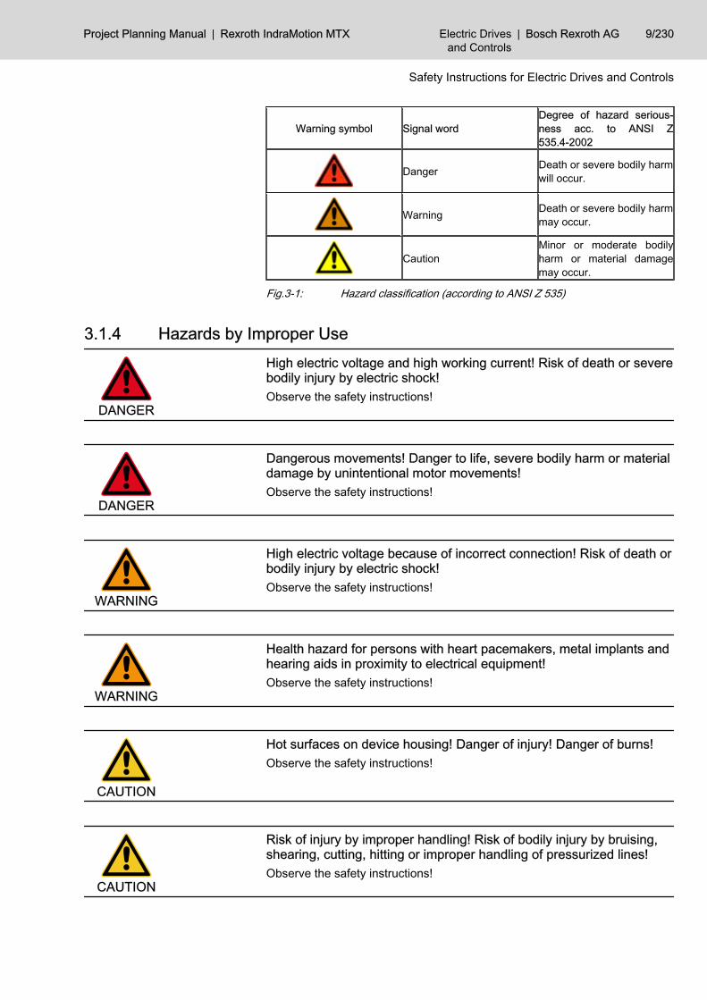
Warning symbol Signal wordDegree of hazard serious‐ness acc. to ANSI Z535.4-2002
Danger Death or severe bodily harmwill occur.
Warning Death or severe bodily harmmay occur.
CautionMinor or moderate bodilyharm or material damagemay occur.
Fig.3-1: Hazard classification (according to ANSI Z 535)
3.1.4 Hazards by Improper Use
DANGER
High electric voltage and high working current! Risk of death or severebodily injury by electric shock!Observe the safety instructions!
DANGER
Dangerous movements! Danger to life, severe bodily harm or materialdamage by unintentional motor movements!Observe the safety instructions!
WARNING
High electric voltage because of incorrect connection! Risk of death orbodily injury by electric shock!Observe the safety instructions!
WARNING
Health hazard for persons with heart pacemakers, metal implants andhearing aids in proximity to electrical equipment!Observe the safety instructions!
CAUTION
Hot surfaces on device housing! Danger of injury! Danger of burns!Observe the safety instructions!
CAUTION
Risk of injury by improper handling! Risk of bodily injury by bruising,shearing, cutting, hitting or improper handling of pressurized lines!Observe the safety instructions!
Project Planning Manual | Rexroth IndraMotion MTX Electric Drivesand Controls
| Bosch Rexroth AG 9/230
Safety Instructions for Electric Drives and Controls

CAUTION
Risk of injury by improper handling of batteries!Observe the safety instructions!
3.2 Instructions with Regard to Specific Dangers3.2.1 Protection Against Contact with Electrical Parts and Housings
This section concerns devices and drive components with voltagesof more than 50 Volt.
Contact with parts conducting voltages above 50 Volts can cause personaldanger and electric shock. When operating electrical equipment, it is unavoid‐able that some parts of the devices conduct dangerous voltage.
DANGER
High electrical voltage! Danger to life, electric shock and severe bodilyinjury!● Only those trained and qualified to work with or on electrical equipment
are permitted to operate, maintain and repair this equipment.● Follow general construction and safety regulations when working on pow‐
er installations.● Before switching on the device, the equipment grounding conductor must
have been non-detachably connected to all electrical equipment in ac‐cordance with the connection diagram.
● Do not operate electrical equipment at any time, even for brief measure‐ments or tests, if the equipment grounding conductor is not permanentlyconnected to the mounting points of the components provided for thispurpose.
● Before working with electrical parts with voltage potentials higher than50 V, the device must be disconnected from the mains voltage or powersupply unit. Provide a safeguard to prevent reconnection.
● With electrical drive and filter components, observe the following:Wait 30 minutes after switching off power to allow capacitors to dischargebefore beginning to work. Measure the electric voltage on the capacitorsbefore beginning to work to make sure that the equipment is safe to touch.
● Never touch the electrical connection points of a component while poweris turned on. Do not remove or plug in connectors when the componenthas been powered.
● Install the covers and guards provided with the equipment properly beforeswitching the device on. Before switching the equipment on, cover andsafeguard live parts safely to prevent contact with those parts.
● A residual-current-operated circuit-breaker or r.c.d. cannot be used forelectric drives! Indirect contact must be prevented by other means, forexample, by an overcurrent protective device according to the relevantstandards.
● Secure built-in devices from direct touching of electrical parts by providingan external housing, for example a control cabinet.
10/230 Bosch Rexroth AG | Electric Drivesand Controls
Rexroth IndraMotion MTX | Project Planning Manual
Safety Instructions for Electric Drives and Controls

For electrical drive and filter components with voltages of more than50 volts, observe the following additional safety instructions.
DANGER
High housing voltage and high leakage current! Risk of death or bodilyinjury by electric shock!● Before switching on, the housings of all electrical equipment and motors
must be connected or grounded with the equipment grounding conductorto the grounding points. This is also applicable before short tests.
● The equipment grounding conductor of the electrical equipment and thedevices must be non-detachably and permanently connected to the powersupply unit at all times. The leakage current is greater than 3.5 mA.
● Over the total length, use copper wire of a cross section of a minimum of10 mm2 for this equipment grounding connection!
● Before commissioning, also in trial runs, always attach the equipmentgrounding conductor or connect to the ground wire. Otherwise, high vol‐tages may occur at the housing causing electric shock.
3.2.2 Protection Against Electric Shock by Protective Extra-Low VoltageProtective extra-low voltage is used to allow connecting devices with basic in‐sulation to extra-low voltage circuits.All connections and terminals with voltages between 5 and 50 volts at Rexrothproducts are PELV systems. 1) It is therefore allowed to connect devicesequipped with basic insulation (such as programming devices, PCs, notebooks,display units) to these connections and terminals.
WARNING
High electric voltage by incorrect connection! Risk of death or bodilyinjury by electric shock!If extra-low voltage circuits of devices containing voltages and circuits of morethan 50 volts (e.g. the mains connection) are connected to Rexroth products,the connected extra-low voltage circuits must comply with the requirements forPELV. 2)
3.2.3 Protection Against Dangerous MovementsDangerous movements can be caused by faulty control of connected motors.Some common examples are:● improper or wrong wiring of cable connections● incorrect operation of the equipment components● wrong input of parameters before operation● malfunction of sensors, encoders and monitoring devices● defective components● software or firmware errorsDangerous movements can occur immediately after equipment is switched onor even after an unspecified time of trouble-free operation.
1) "Protective Extra-Low Voltage"2) "Protective Extra-Low Voltage"
Project Planning Manual | Rexroth IndraMotion MTX Electric Drivesand Controls
| Bosch Rexroth AG 11/230
Safety Instructions for Electric Drives and Controls

The monitoring in the drive components will normally be sufficient to avoid faultyoperation in the connected drives. Regarding personal safety, especially thedanger of bodily harm and material damage, this alone cannot be relied uponto ensure complete safety. Until the integrated monitoring functions becomeeffective, it must be assumed in any case that faulty drive movements will occur.The extent of faulty drive movements depends upon the type of control and thestate of operation.
12/230 Bosch Rexroth AG | Electric Drivesand Controls
Rexroth IndraMotion MTX | Project Planning Manual
Safety Instructions for Electric Drives and Controls

DANGER
Dangerous movements! Danger to life, risk of injury, severe bodily harmor material damage!● Ensure personal safety by means of qualified and tested higher-level
monitoring devices or measures integrated in the installation.These measures have to be provided for by the user according to thespecific conditions within the installation and a hazard and fault analysis.The safety regulations applicable for the installation have to be taken intoconsideration. Unintended machine motion or other malfunction is possi‐ble if safety devices are disabled, bypassed or not activated.
To avoid accidents, bodily harm and/or material damage:● Keep free and clear of the machine’s range of motion and moving parts.
Possible measures to prevent people from accidentally entering themachine’s range of motion:– use safety fences– use safety guards– use protective coverings– install light curtains or light barriers
● Fences and coverings must be strong enough to resist maximum possiblemomentum.
● Mount the emergency stop switch in the immediate reach of the operator.Verify that the emergency stop works before startup. Don’t operate thedevice if the emergency stop is not working.
● Isolate the drive power connection by means of an emergency stop circuitor use a safety related starting lockout to prevent unintentional start.
● Make sure that the drives are brought to a safe standstill before accessingor entering the danger zone.
● Additionally secure vertical axes against falling or dropping after switchingoff the motor power by, for example:– mechanically securing the vertical axes,– adding an external braking/ arrester/ clamping mechanism or– ensuring sufficient equilibration of the vertical axes.
● The standard equipment motor brake or an external brake controlled di‐rectly by the drive controller are not sufficient to guarantee personalsafety!
● Disconnect electrical power to the equipment using a master switch andsecure the switch against reconnection for:– maintenance and repair work– cleaning of equipment– long periods of discontinued equipment use
● Prevent the operation of high-frequency, remote control and radio equip‐ment near electronics circuits and supply leads. If the use of such devicescannot be avoided, verify the system and the installation for possible mal‐functions in all possible positions of normal use before initial startup. Ifnecessary, perform a special electromagnetic compatibility (EMC) test onthe installation.
Project Planning Manual | Rexroth IndraMotion MTX Electric Drivesand Controls
| Bosch Rexroth AG 13/230
Safety Instructions for Electric Drives and Controls

3.2.4 Protection Against Magnetic and Electromagnetic Fields During Oper‐ation and Mounting
Magnetic and electromagnetic fields generated by current-carrying conductorsand permanent magnets in motors represent a serious personal danger tothose with heart pacemakers, metal implants and hearing aids.
WARNING
Health hazard for persons with heart pacemakers, metal implants andhearing aids in proximity to electrical equipment!● Persons with heart pacemakers and metal implants are not permitted to
enter following areas:– Areas in which electrical equipment and parts are mounted, being
operated or commissioned.– Areas in which parts of motors with permanent magnets are being
stored, repaired or mounted.● If it is necessary for somebody with a pacemaker to enter such an area,
a doctor must be consulted prior to doing so. The noise immunity of pres‐ent or future implanted heart pacemakers differs greatly so that no generalrules can be given.
● Those with metal implants or metal pieces, as well as with hearing aids,must consult a doctor before they enter the areas described above. Oth‐erwise health hazards may occur.
3.2.5 Protection Against Contact with Hot Parts
CAUTION
Hot surfaces at motor housings, on drive controllers or chokes! Dangerof injury! Danger of burns!● Do not touch surfaces of device housings and chokes in the proximity of
heat sources! Danger of burns!● Do not touch housing surfaces of motors! Danger of burns!● According to the operating conditions, temperatures can be higher than
60 °C, 140°F during or after operation.● Before accessing motors after having switched them off, let them cool
down for a sufficiently long time. Cooling down can require up to 140 mi‐nutes! Roughly estimated, the time required for cooling down is five timesthe thermal time constant specified in the Technical Data.
● After switching drive controllers or chokes off, wait 15 minutes to allowthem to cool down before touching them.
● Wear safety gloves or do not work at hot surfaces.● For certain applications, the manufacturer of the end product, machine or
installation, according to the respective safety regulations, has to takemeasures to avoid injuries caused by burns in the end application. Thesemeasures can be, for example: warnings, guards (shielding or barrier),technical documentation.
3.2.6 Protection During Handling and MountingIn unfavorable conditions, handling and mounting certain parts and compo‐nents in an improper way can cause injuries.
14/230 Bosch Rexroth AG | Electric Drivesand Controls
Rexroth IndraMotion MTX | Project Planning Manual
Safety Instructions for Electric Drives and Controls

CAUTION
Risk of injury by improper handling! Bodily injury by bruising, shearing,cutting, hitting!● Observe the general construction and safety regulations on handling and
mounting.● Use suitable devices for mounting and transport.● Avoid jamming and bruising by appropriate measures.● Always use suitable tools. Use special tools if specified.● Use lifting equipment and tools in the correct manner.● If necessary, use suitable protective equipment (for example safety gog‐
gles, safety shoes, safety gloves).● Do not stand under hanging loads.● Immediately clean up any spilled liquids because of the danger of skidding.
3.2.7 Battery SafetyBatteries consist of active chemicals enclosed in a solid housing. Therefore,improper handling can cause injury or material damage.
CAUTION
Risk of injury by improper handling!● Do not attempt to reactivate low batteries by heating or other methods (risk
of explosion and cauterization).● Do not recharge the batteries as this may cause leakage or explosion.● Do not throw batteries into open flames.● Do not dismantle batteries.● When replacing the battery/batteries do not damage electrical parts in‐
stalled in the devices.● Only use the battery types specified by the manufacturer.
Environmental protection and disposal! The batteries contained inthe product are considered dangerous goods during land, air, andsea transport (risk of explosion) in the sense of the legal regulations.Dispose of used batteries separate from other waste. Observe thelocal regulations in the country of assembly.
3.2.8 Protection Against Pressurized SystemsAccording to the information given in the Project Planning Manuals, motorscooled with liquid and compressed air, as well as drive controllers, can be par‐tially supplied with externally fed, pressurized media, such as compressed air,hydraulics oil, cooling liquids and cooling lubricating agents. Improper handlingof the connected supply systems, supply lines or connections can cause injuriesor material damage.
Project Planning Manual | Rexroth IndraMotion MTX Electric Drivesand Controls
| Bosch Rexroth AG 15/230
Safety Instructions for Electric Drives and Controls

CAUTION
Risk of injury by improper handling of pressurized lines!● Do not attempt to disconnect, open or cut pressurized lines (risk of explo‐
sion).● Observe the respective manufacturer's operating instructions.● Before dismounting lines, relieve pressure and empty medium.● Use suitable protective equipment (for example safety goggles, safety
shoes, safety gloves).● Immediately clean up any spilled liquids from the floor.
Environmental protection and disposal! The agents used to operatethe product might not be economically friendly. Dispose of ecolog‐ically harmful agents separately from other waste. Observe the localregulations in the country of assembly.
16/230 Bosch Rexroth AG | Electric Drivesand Controls
Rexroth IndraMotion MTX | Project Planning Manual
Safety Instructions for Electric Drives and Controls

4 Configurations4.1 Configuration of the PLC NC Bit Interface4.1.1 General
After a new IndraWorks project has been created and the screen (e.g. HMI BTV40_1) and the IndraMotion MTXP60 control have been set up, you will find theconfiguration of the PLC NC bit interface as a subnode of this control. Therespective node name is "NC PLC Interface".The bit interface consists of the global interface (General Interface), the channelinterface, the axis interface and the spindle interface. The Machine Status Dis‐play can also be added to the bit interface .The configuration of the MSD is described in chapter 12.1 " Configuration ofMachine Status Display (MSD) " on page 199.By default, only the interface for General Data exists and is preset when a newproject is created.
Fig.4-1: The preset bit interface with the Properties dialog box for the GeneralInterface
The signals of the bit interface should always be viewed from the viewpoint ofthe PLC. For example, the signals from qGen are General Interface signalsfrom the PLC to the NC.
4.1.2 The General InterfaceThe Global Interface is always present and cannot be deleted. The symbolicname for output signals is "qGen" and the start address for the structureMT_qGif_Type is 5800. The symbolic name for input signals is "iGen" and thestart address for the structure MT_iGif_Type is 5800. You can enter the prop‐erties dialog by double-clicking on the node "General Interface" (or in thecontext menu via "Open"). In this Properties dialog box, you can change thepreassigned names and addresses for the inputs and outputs; you can alsoassign comments.
4.1.3 The Channel Interface (Channel Interface)The IndraMotion MTX supports a switching function channel (channel 0) andup to twelve machining channels. By default, no channels are yet defined. Newchannels are created by clicking the contextual menu on the "Channel Interfa‐ces" node.
Project Planning Manual | Rexroth IndraMotion MTX Electric Drivesand Controls
| Bosch Rexroth AG 17/230
Configurations
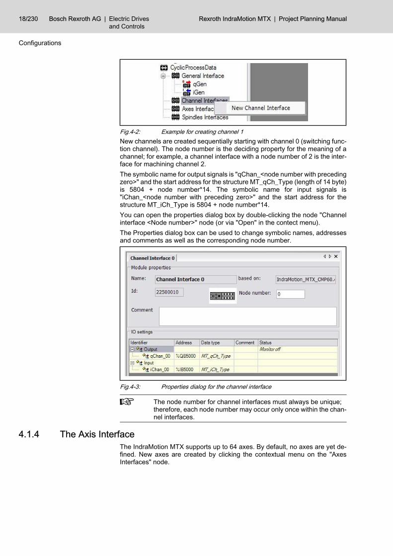
Fig.4-2: Example for creating channel 1New channels are created sequentially starting with channel 0 (switching func‐tion channel). The node number is the deciding property for the meaning of achannel; for example, a channel interface with a node number of 2 is the inter‐face for machining channel 2.The symbolic name for output signals is "qChan_<node number with precedingzero>" and the start address for the structure MT_qCh_Type (length of 14 byte)is 5804 + node number*14. The symbolic name for input signals is"iChan_<node number with preceding zero>" and the start address for thestructure MT_iCh_Type is 5804 + node number*14.You can open the properties dialog box by double-clicking the node "Channelinterface <Node number>" node (or via "Open" in the contect menu).The Properties dialog box can be used to change symbolic names, addressesand comments as well as the corresponding node number.
Fig.4-3: Properties dialog for the channel interface
The node number for channel interfaces must always be unique;therefore, each node number may occur only once within the chan‐nel interfaces.
4.1.4 The Axis InterfaceThe IndraMotion MTX supports up to 64 axes. By default, no axes are yet de‐fined. New axes are created by clicking the contextual menu on the "AxesInterfaces" node.
18/230 Bosch Rexroth AG | Electric Drivesand Controls
Rexroth IndraMotion MTX | Project Planning Manual
Configurations

Fig.4-4: Example for creating axis 2New axes are created sequentially starting with axis 1. The node number is thedeciding property for the meaning of an axis; for example, an axis interface witha node number of 4 is the interface for axis 4.The symbolic name for output signals is "qAxis_<node number with precedingzero>" and the start address for the structure MT_qAx_Type (length of 12 byte)is 5986 + node number*12. The symbolic name for input signals is "iAxis_<nodenumber with preceding zero>" and the start address for the structureMT_iAx_Type is 5986 + node number*12.You can open the properties dialog box by double-clicking the node "Axis in‐terface <Node number>" node (or via "Open" in the context menu).The Properties dialog box can be used to change symbolic names, addressesand comments as well as the corresponding node number.
Fig.4-5: Properties dialog for the axis interface
The node number for axis interfaces must always be unique; there‐fore, each node number may occur only once within the axis inter‐faces.
4.1.5 The Spindle InterfaceThe IndraMotion MTX supports up to 32 spindles. By default, no spindles areyet defined. New spindles are created by clicking the contextual menu on the"Spindles Interfaces" node.
Project Planning Manual | Rexroth IndraMotion MTX Electric Drivesand Controls
| Bosch Rexroth AG 19/230
Configurations
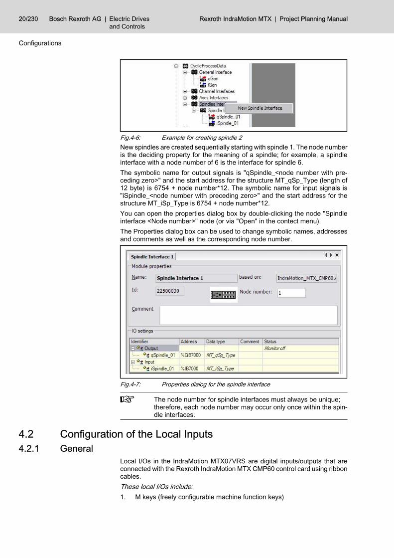
Fig.4-6: Example for creating spindle 2New spindles are created sequentially starting with spindle 1. The node numberis the deciding property for the meaning of a spindle; for example, a spindleinterface with a node number of 6 is the interface for spindle 6.The symbolic name for output signals is "qSpindle_<node number with pre‐ceding zero>" and the start address for the structure MT_qSp_Type (length of12 byte) is 6754 + node number*12. The symbolic name for input signals is"iSpindle_<node number with preceding zero>" and the start address for thestructure MT_iSp_Type is 6754 + node number*12.You can open the properties dialog box by double-clicking the node "Spindleinterface <Node number>" node (or via "Open" in the contect menu).The Properties dialog box can be used to change symbolic names, addressesand comments as well as the corresponding node number.
Fig.4-7: Properties dialog for the spindle interface
The node number for spindle interfaces must always be unique;therefore, each node number may occur only once within the spin‐dle interfaces.
4.2 Configuration of the Local Inputs4.2.1 General
Local I/Os in the IndraMotion MTX07VRS are digital inputs/outputs that areconnected with the Rexroth IndraMotion MTX CMP60 control card using ribboncables.These local I/Os include:1. M keys (freely configurable machine function keys)
20/230 Bosch Rexroth AG | Electric Drivesand Controls
Rexroth IndraMotion MTX | Project Planning Manual
Configurations
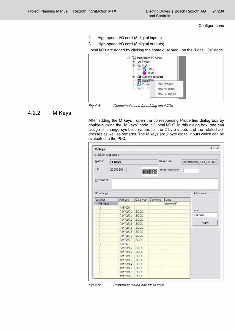
2. High-speed I/O card (8 digital inputs)3. High-speed I/O card (8 digital outputs)Local I/Os are added by clicking the contextual menu on the "Local IOs" node.
Fig.4-8: Contextual menu for adding local I/Os
4.2.2 M KeysAfter adding the M keys , open the corresponding Properties dialog box bydouble-clicking the "M keys" node in "Local I/Os". In this dialog box, one canassign or change symbolic names for the 2 byte inputs and the related ad‐dresses as well as remarks. The M keys are 2 byte digital inputs which can beevaluated in the PLC.
Fig.4-9: Properties dialog box for M keys
Project Planning Manual | Rexroth IndraMotion MTX Electric Drivesand Controls
| Bosch Rexroth AG 21/230
Configurations

The function of each machine function key is defined in the HMIconfiguration.
4.2.3 Digital Inputs of the IO Card (HS Input)After adding the digital inputs of the I/O card, open the corresponding Propertiesdialog box by double-clicking the "HS input" node in "Local I/Os". In this dialogbox, one can assign or change symbolic names for the input byte and relatedaddresses as well as remarks. The 8 digital inputs of the I/O cards can be eval‐uated both in the PLC and in the NC.
Fig.4-10: Properties dialog for HS input
The NC-side configuration is described in manual "Machine pa‐rameter".
4.2.4 Digital Outputs of the IO Card (HS Output)After adding the digital outputs of the I/O card, open the related properties dialogbox by double-clicking on the "HS Output" node in "Local I/Os". In this dialogbox, one can assign or change symbolic names for the output byte and relatedaddresses as well as remarks. The 8 digital inputs of the I/O cards can be eval‐uated both in the PLC and in the NC.
22/230 Bosch Rexroth AG | Electric Drivesand Controls
Rexroth IndraMotion MTX | Project Planning Manual
Configurations

Fig.4-11: Properties dialog box for HS output
The NC-side configuration is described in manual "Machine pa‐rameter".
4.3 Profibus Configuration4.3.1 General
The Rexroth IndraMotion MTX CMP60 control card has an onboard ProfibusDP Master. The ASPC2 Profibus controller is operated in "Dual Port" mode.512 kB of memory is available. The physical interface is optically decoupled.
4.3.2 The Profibus MasterThe Properties dialog box of the MTX CMP60 DP Master is opened by double-clicking the "Profibus/M" node. Among other things, the bus address and thebaud rate can be set here.
Project Planning Manual | Rexroth IndraMotion MTX Electric Drivesand Controls
| Bosch Rexroth AG 23/230
Configurations

Fig.4-12: Properties dialog box of the MTX CMP60 DP Master
Modified settings will not until the next download into PLC be acti‐vated!
Additional optimization settings are possible by setting Optimization to "Man‐ual". But the following note must be observed:
CAUTION
Modifications on the standard bus parameters can lead to unpredictablebehavior of profibus DP!The bus parameter may only be modified by specifically instructed Profibus DBspecialists!
4.3.3 Importing Device Master FilesThe DP slaves of most Bosch Rexroth products are provided automaticallyduring installation. If additional specific DP slaves are required nevertheless,they can be announced to the system by importing the associated GSD files.To start the import of GSD files , right-click on the "Profibus/M" node.
Fig.4-13: Contextual menu of the "Profibus/M" node
24/230 Bosch Rexroth AG | Electric Drivesand Controls
Rexroth IndraMotion MTX | Project Planning Manual
Configurations
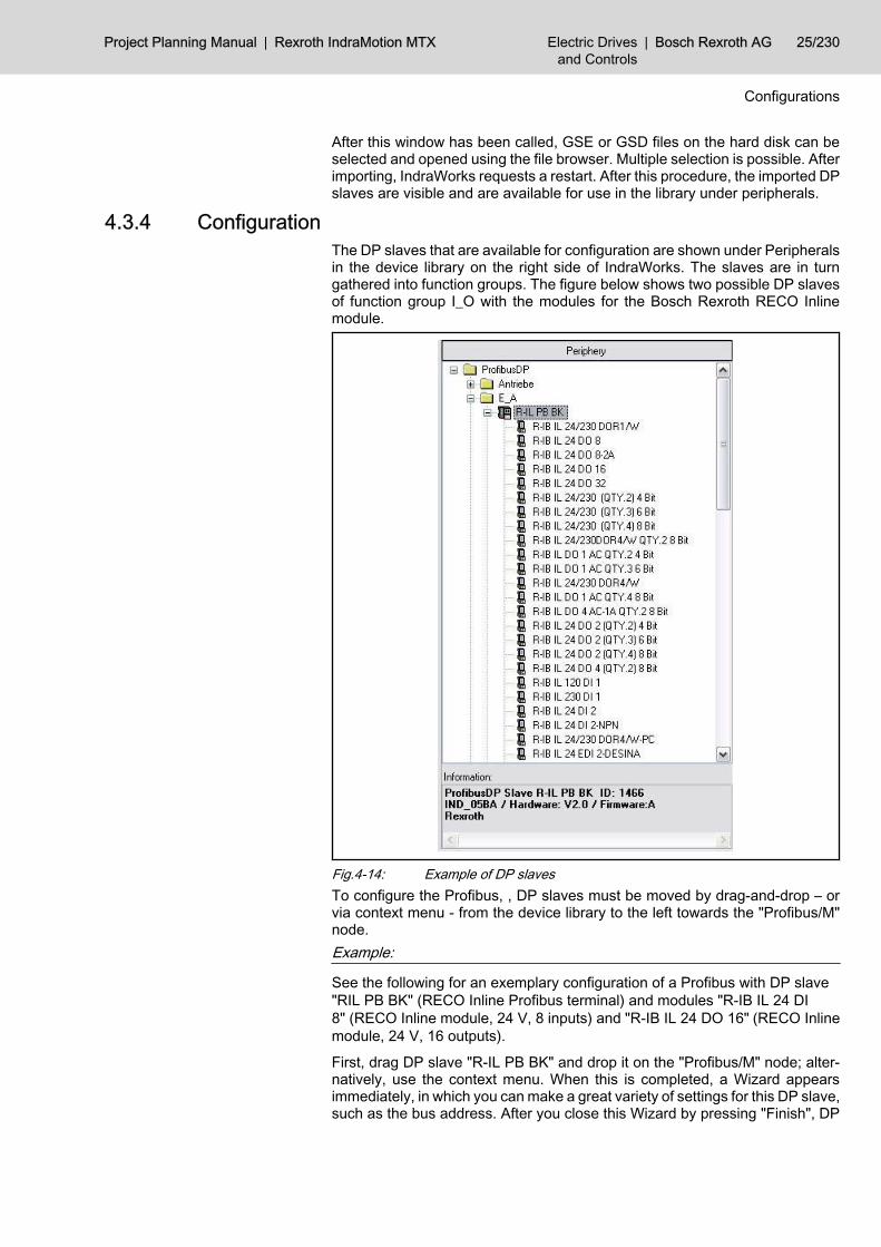
After this window has been called, GSE or GSD files on the hard disk can beselected and opened using the file browser. Multiple selection is possible. Afterimporting, IndraWorks requests a restart. After this procedure, the imported DPslaves are visible and are available for use in the library under peripherals.
4.3.4 ConfigurationThe DP slaves that are available for configuration are shown under Peripheralsin the device library on the right side of IndraWorks. The slaves are in turngathered into function groups. The figure below shows two possible DP slavesof function group I_O with the modules for the Bosch Rexroth RECO Inlinemodule.
Fig.4-14: Example of DP slavesTo configure the Profibus, , DP slaves must be moved by drag-and-drop – orvia context menu - from the device library to the left towards the "Profibus/M"node.Example:
See the following for an exemplary configuration of a Profibus with DP slave"RIL PB BK" (RECO Inline Profibus terminal) and modules "R-IB IL 24 DI8" (RECO Inline module, 24 V, 8 inputs) and "R-IB IL 24 DO 16" (RECO Inlinemodule, 24 V, 16 outputs).
First, drag DP slave "R-IL PB BK" and drop it on the "Profibus/M" node; alter‐natively, use the context menu. When this is completed, a Wizard appearsimmediately, in which you can make a great variety of settings for this DP slave,such as the bus address. After you close this Wizard by pressing "Finish", DP
Project Planning Manual | Rexroth IndraMotion MTX Electric Drivesand Controls
| Bosch Rexroth AG 25/230
Configurations

slave "R-IL PB BK" is now one of the nodes of the DP master. Then, dragmodules "R-IB IL 24 DI 8" and "R-IB IL 16 DO 16" and drop them on the nodeof the corresponding DP slave; alternatively, use the context menu. After eachdrag-and-drop procedure is completed, a Wizard appears, in which you canmake very many settings, such as symbolic names, addresses and comments.The completed Profibus configuration – with the default values – appears asfollows:
Fig.4-15: Sample Profibus configurationThe number before the name of the DP slave indicates the set bus address.
4.3.5 Setting Addresses in a DP SlaveThe addresses of DP slave participants are always set in the Properties dialogbox, which is opened by double-clicking the DP slave or a subordinate module.If a series of addresses without gaps is desired within a DP slave, addressingin the Properties dialog of the DP slave must take place in the "I/O settings"register card of the DP slave. The following example shows a series of ad‐dresses without any gaps for DP slave "R-IL PBBK":
Fig.4-16: Example of a series of addresses without any gapsIndraWorks also supports completely random addressing within a DP slave. Todo this, however, addressing must be carried out separately in the Propertiesdialog box of each individual module.
26/230 Bosch Rexroth AG | Electric Drivesand Controls
Rexroth IndraMotion MTX | Project Planning Manual
Configurations

Example:
Random addressing for the DP slave "R-IL PB BK":
Fig.4-17: Example of random addressing
Addressing using the Properties dialog box of the DP slave over‐writes any addressing previously executed in the modules of the DPslave.
Project Planning Manual | Rexroth IndraMotion MTX Electric Drivesand Controls
| Bosch Rexroth AG 27/230
Configurations

Bosch Rexroth AG | Electric Drivesand Controls
Rexroth IndraMotion MTX | Project Planning Manual

5 Global Interface Signals5.1 Overview Global Interface Signals5.1.1 General
Global interface signals are higher level signals used with functions relating tothe NC as a whole.
5.1.2 Overview Output Signals (PLC → NC)Bit Symbol. Addr. PLC output signal Bit Symbol. Addr. PLC output signal
0.0 qGen_Reset System control reset 1.0 qGen_StrokeInhibit Stroke inhibit
0.1 qGen_EditInhibit Edit inhibit 1.1 qGen_StrokeReserv Stroke reservation
0.2 qGen_DelErrInfo Clear error info 1.2 qGen_StrokeRel Stroke on
0.3 - res. 1.3 - res.
0.4 - res. 1.4 - res.
0.5 - res. 1.5 - res.
0.6 - res. 1.6 - res.
0.7 - res. 1.7 - res.
2.0 - res. 3.0 - res.
2.1 - res. 3.1 - res.
2.2 - res. 3.2 - res.
2.3 - res. 3.3 - res.
2.4 - res. 3.4 - res.
2.5 - res. 3.5 - res.
2.6 - res. 3.6 - res.
2.7 - res. 3.7 - res.
Fig.5-1: Overview of output signals (PLC → NC)
5.1.3 Overview Input Signals (NC → PLC)Bit Symbol. Addr. PLC input signal Bit Symbol. Addr. PLC input signal
0.0 - res. 1.0 iGen_StrokeIntend Stroke intended
0.1 iGen_HardwareState Hardware warning 1.1 iGen_NoStroke Stroke is not running
0.2 - res. 1.2 - res.
0.3 - res. 1.3 - res.
0.4 - res. 1.4 - res.
0.5 - res. 1.5 - res.
0.6 - res. 1.6 - res.
0.7 - res. 1.7 - res.
2.0 - res. 3.0 - res.
2.1 - res. 3.1 - res.
2.2 - res. 3.2 - res.
Project Planning Manual | Rexroth IndraMotion MTX Electric Drivesand Controls
| Bosch Rexroth AG 29/230
Global Interface Signals

Bit Symbol. Addr. PLC input signal Bit Symbol. Addr. PLC input signal
2.3 - res. 3.3 - res.
2.4 - res. 3.4 - res.
2.5 - res. 3.5 - res.
2.6 - res. 3.6 - res.
2.7 - res. 3.7 - res.
Fig.5-2: Overview of input signals (NC -> PLC)
5.2 Signal Description5.2.1 Output Signals (PLC→ NC) System Reset qGen_Reset
This signal acts on all channels of the NC. Its effect on the individual channelsis identical with a control reset of each single channel.System reset affects:● axis-related signals of the NC to the PLC● channel-related signals of the NC:
– Control reset executed– NC ready– Program is running
1: A system reset is effected on all channels.0: No effect.
Edit Inhibit Function qGen_EditInhibit
Edit inhibit is in the MTX 07VRS without function!
Edit inhibit prohibits the user from performing certain operations on the NC.Only user actions directly related with the production process are allowed.The effect of the Edit inhibit is independent of the channel.1: The following functions are either locked or restricted:
● File management● Tables● Editor● Machine parameter administration
0: No effect.
CAUTION
Edit inhibit does not act on tool management.If required, tool management can be locked via the PLC.
User level Edit inhibit applicable
System no
Developer no
MTB no
30/230 Bosch Rexroth AG | Electric Drivesand Controls
Rexroth IndraMotion MTX | Project Planning Manual
Global Interface Signals
Signal level
Signal level
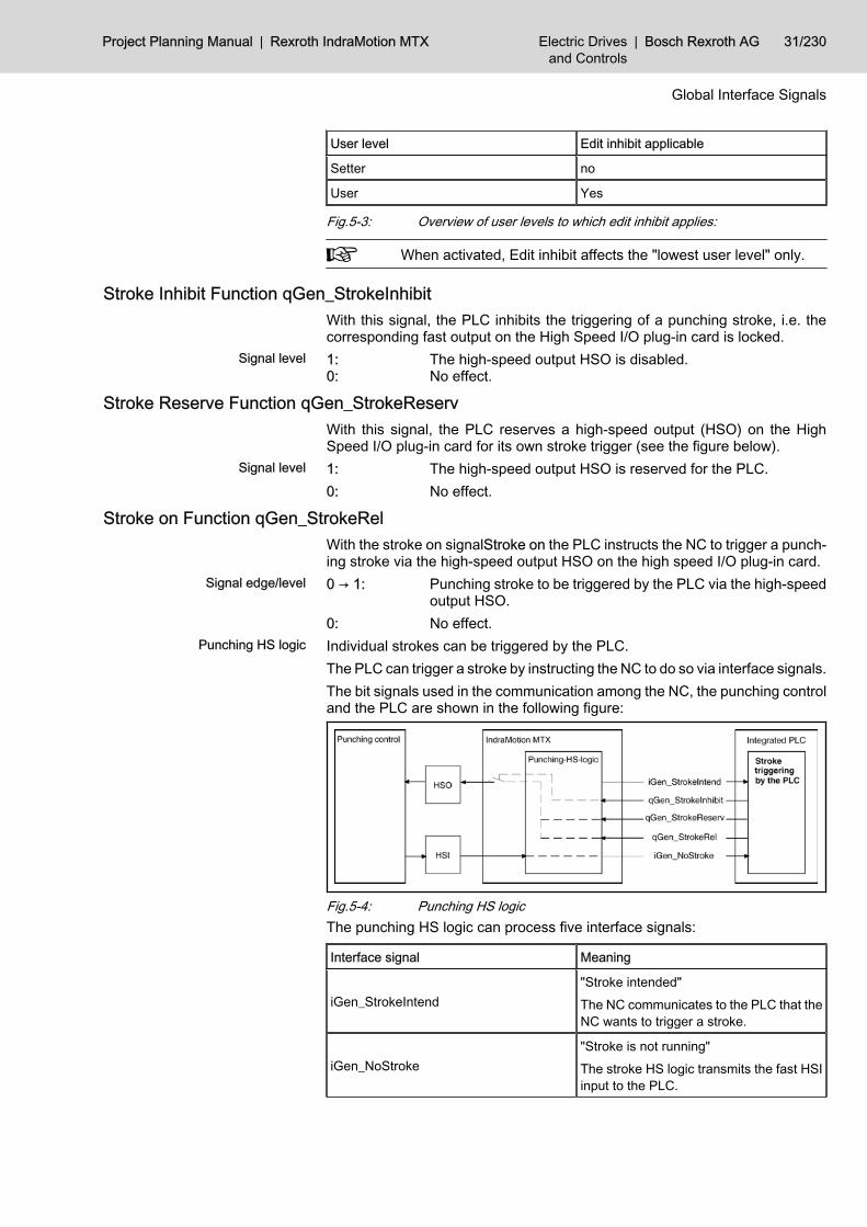
User level Edit inhibit applicable
Setter no
User Yes
Fig.5-3: Overview of user levels to which edit inhibit applies:
When activated, Edit inhibit affects the "lowest user level" only.
Stroke Inhibit Function qGen_StrokeInhibitWith this signal, the PLC inhibits the triggering of a punching stroke, i.e. thecorresponding fast output on the High Speed I/O plug-in card is locked.1: The high-speed output HSO is disabled.0: No effect.
Stroke Reserve Function qGen_StrokeReservWith this signal, the PLC reserves a high-speed output (HSO) on the HighSpeed I/O plug-in card for its own stroke trigger (see the figure below).1: The high-speed output HSO is reserved for the PLC.0: No effect.
Stroke on Function qGen_StrokeRelWith the stroke on signalStroke on the PLC instructs the NC to trigger a punch‐ing stroke via the high-speed output HSO on the high speed I/O plug-in card.0 → 1: Punching stroke to be triggered by the PLC via the high-speed
output HSO.0: No effect.Individual strokes can be triggered by the PLC.The PLC can trigger a stroke by instructing the NC to do so via interface signals.The bit signals used in the communication among the NC, the punching controland the PLC are shown in the following figure:
Fig.5-4: Punching HS logicThe punching HS logic can process five interface signals:
Interface signal Meaning
iGen_StrokeIntend"Stroke intended"The NC communicates to the PLC that theNC wants to trigger a stroke.
iGen_NoStroke"Stroke is not running"The stroke HS logic transmits the fast HSIinput to the PLC.
Project Planning Manual | Rexroth IndraMotion MTX Electric Drivesand Controls
| Bosch Rexroth AG 31/230
Global Interface Signals
Signal level
Signal level
Signal edge/level
Punching HS logic

Interface signal Meaning
qGen_StrokeInhibit"Stroke inhibit"The PLC inhibits the HSO from being set.
qGen_StrokeReserv"Stroke reservation"The PLC reserves the high speed output(HSO) for its own stroke triggering.
qGen_StrokeRel"Stroke on"The PLC instructs the NC to trigger astroke.
Fig.5-5: Interface signalsA punching stroke can be triggered both from the NC and from the PLC:
Fig.5-6: Stroke trigger by the NC
Delete Error info qGen_DelErrInfoSignal "Clear error info" allows to delete via PLC all errors, warnings and mes‐sage entries within the diagnostics memory of diagnostics overview (info dialog)of Rexroth IndraMotion MTX standard user interface. The interface signal hasthe same effect as the "Delete" F key if the F key is set to the "All" status forthe filter.1: Deleting all entries of errors, warnings and messages within a
diagnostics memory.0: No effect.
5.2.2 Input Signals (NC → PLC) Hardware Warning iGen_HardwareState
Signal Hardware Warning is set if one or more of the following conditions arefulfilled:● NC module reports "Overtemperature". This is the case in "CMP60" mod‐
ule if the speed of processor fan is descends under the defined speed.● NC module reports "Battery advance warning".PLC program can evaluate the system data● /SysHwStates/BattFail● /SysHwStates/OverTemp● /SysStates/BdTemp/CpuTempand derive an adequate reaction (see functional description).
32/230 Bosch Rexroth AG | Electric Drivesand Controls
Rexroth IndraMotion MTX | Project Planning Manual
Global Interface Signals
Signal level
Stroke Intended Function iGen_StrokeIntendWith the Stroke intended signal, the NC communicates to the PLC that the NCwants to trigger a punching stroke. If the PLC permits the stroke to be triggered(qGen_StrokeInhibit = 0 and qGen_StrokeReserv = 0), the high speed output(HSO) on the high speed I/O plug-in card is set by the punching (chapter 5.2 "Signal Description" on page 30).1: The NC communicates to the PLC that the NC wants to trigger
a stroke.0: No effect.
'Stroke Is Not Running' Function iGen_NoStrokeThe response signal stroke is not running from the punching control (high speedinput HSI on the high speed I/O plug-in card) is relayed to the PLC.1: Stroke is not running = response signal from the punching con‐
trol to the PLC.0: Stroke running.
Project Planning Manual | Rexroth IndraMotion MTX Electric Drivesand Controls
| Bosch Rexroth AG 33/230
Global Interface Signals
Signal level
Signal level

Bosch Rexroth AG | Electric Drivesand Controls
Rexroth IndraMotion MTX | Project Planning Manual

6 Channel-related Interface Signals6.1 Overview on Channel-related Interface Signals6.1.1 General
The IndraMotion MTX is provided with a Channel structure that allows pro‐cessing several tasks at a time.The channel-related interface signals have mainly an effect on the NC functionsthat are related to the process of the NC parts program.Every channel has its own interface; i.e. with n-channels, the interface depictedin sections chapter 6.1.2 "Overview of Output Signals (PLC → NC) " on page35 and chapter 6.1.3 "Overview of Input Signals (PLC → NC)" on page 37is mapped n-times on the corresponding markers.In addition to the channel-related interface, the axis-related interface is of sig‐nificance to the machining axes combined to form a channel as well as to theauxiliary axes.At least 2 channels must always be entered:● Channel 0 for switching functions● Channel 1 for a machining channelThe following description shows the interface signals for a channel.
6.1.2 Overview of Output Signals (PLC → NC) Bit Symbol. Addr. PLC output signal Bit Symbol. Addr. PLC output signal
0.0 qCh_OpModeSel_00 Sel. operating mode forbit 0 1.0 qCh_OpModePlc PLC operating mode
0.1 qCh_OpModeSel_01 Sel. operating mode forbit 1 1.1 qCh_Restart Automatic restart
0.2 qCh_OpModeSel_02 Sel. operating mode forbit 2 1.2 qCh_NCStart Cycle start
0.3 qCh_OpModeSel_03 Sel. operating mode forbit 3 1.3 qCh_TransferLock Read lock
0.4 - res. 1.4 qCh_FeedHold Feed stop
0.5 - res. 1.5 qCh_FeedStop Feed inhibit
0.6 - res. 1.6 - res.
0.7 - res. 1.7 qCh_ReSelOff Autom. reselection off
2.0 qCh_CtrlReset Control reset 3.0 qCh_ASub1 Asynchr. subprogr. 1
2.1 - res. 3.1 qCh_ASub2 Asynchr. subprogr. 2
2.2 qCh_CancDist Cancel distance to go 3.2 qCh_ASub3 Asynchr. subprogr. 3
2.3 qCh_NextBlk Switch to next block 3.3 qCh_ASub4 Asynchr. subprogr. 4
2.4 - res. 3.4 qCh_ASub5 Asynchr. subprogr. 5
2.5 - res. 3.5 qCh_ASub6 Asynchr. subprogr. 6
2.6 qCh_RetCont Return to path 3.6 qCh_ASub7 Asynchr. subprogr. 7
2.7 qCh_Retract Rapid retraction 3.7 qCh_ASub8 Asynchr. subprogr. 8
4.0 qCh_JogPlusWcs WCS manual + 5.0 qCh_BlkSlash Block slash
Project Planning Manual | Rexroth IndraMotion MTX Electric Drivesand Controls
| Bosch Rexroth AG 35/230
Channel-related Interface Signals

Bit Symbol. Addr. PLC output signal Bit Symbol. Addr. PLC output signal
4.1 qCh_JogMinusWcs WCS manual - 5.1 qCh_OptStop Optional stop
4.2 - res. 5.2 qCh_OptJump Conditional jump
4.3 - res. 5.3 - res.
4.4 qCh_Handw‐SelWcs_00 Select handwheel Bit0 5.4 qCh_RedRap Limit rapid travel
4.5 qCh_Handw‐SelWcs_01
Handwheel selection bit1 5.5 - res.
4.6 qCh_HandwDirWcs Handwheel direction 5.6 - res.
4.7 qCh_HandwPosMode Position handwheel 5.7 qCh_Override100 Override100%
6.0 qCh_Override_00 Override bit 0 7.0 qCh_Override_08 Override bit 8
6.1 qCh_Override_01 Override bit 1 7.1 qCh_Override_09 Override bit 9
6.2 qCh_Override_02 Override bit 2 7.2 qCh_Override_10 Override bit 10
6.3 qCh_Override_03 Override bit 3 7.3 qCh_Override_11 Override bit 11
6.4 qCh_Override_04 Override bit 4 7.4 qCh_Override_12 Override bit 12
6.5 qCh_Override_05 Override bit 5 7.5 qCh_Override_13 Override bit 13
6.6 qCh_Override_06 Override bit 6 7.6 qCh_Override_14 Override bit 14
6.7 qCh_Override_07 Override bit 7 7.7 qCh_Override_15 Override bit 15
8.0 qCh_Custom1 Customer input 1 9.0 qCh_OnlCorrWcs Online correction re‐lease
8.1 qCh_Custom2 Customer input 2 9.1 qCh_OnlCorrWcsDir Online correction direc‐tion
8.2 qCh_Custom3 Customer input 3 9.2 - res.
8.3 qCh_Custom4 Customer input 4 9.3 - res.
8.4 qCh_Custom5 Customer input 5 9.4 - res.
8.5 qCh_Custom6 Customer input 6 9.5 - res.
8.6 qCh_Custom7 Customer input 7 9.6 qCh_CoordCoupleOff Decoupling
8.7 qCh_Custom8 Customer input 8 9.7 qCh_TangTRotRel TTL release
10.0 - res. 11.0 - res.
10.1 - res. 11.1 - res.
10.2 - res. 11.2 - res.
10.3 - res. 11.3 - res.
10.4 - res. 11.4 - res.
10.5 - res. 11.5 - res.
10.6 - res. 11.6 - res.
10.7 - res. 11.7 - res.
12.0 - res. 13.0 qCH_TestFeed Test feed
12.1 - res. 13.1 qCH_TestRap Test rapid traverse
12.2 - res. 13.2 - res.
12.3 - res. 13.3 - res.
36/230 Bosch Rexroth AG | Electric Drivesand Controls
Rexroth IndraMotion MTX | Project Planning Manual
Channel-related Interface Signals

Bit Symbol. Addr. PLC output signal Bit Symbol. Addr. PLC output signal
12.4 - res. 13.4 - res.
12.5 - res. 13.5 - res.
12.6 - res. 13.6 - res.
12.7 - res. 13.7 - res.
Fig.6-1: Overview of output signals (PLC → NC)
6.1.3 Overview of Input Signals (PLC → NC)Bit Symbol. Addr. PLC input signal Bit Symbol. Addr. PLC input signal
0.0 iCh_OpMode_00 Sel. operating mode forbit 0 1.0 iCh_DryRun Test mode
0.1 iCh_OpMode_01 Sel. operating mode forbit 1 1.1 iCh_NCReady NC ready
0.2 iCh_OpMode_02 Sel. operating mode forbit 2 1.2 iCh_ProgRun Program is running
0.3 iCh_OpMode_03 Sel. operating mode forbit 3 1.3 iCh_TransferLockAct Block transfer inhibit ac‐
tive
0.4 res. 1.4 iCh_FeedHoldAct Feed hold active
0.5 res. 1.5 - res.
0.6 res. 1.6 iCh_ProgStopM0 Program stop M0
0.7 res. 1.7 iCh_ProgStopM30 Program stop M30
2.0 iCh_Reset Channel reset 3.0 iCh_ASub1 Asynchr. subprogr. 1
2.1 - res. 3.1 iCh_ASub2 Asynchr. subprogr. 2
2.2 - res. 3.2 iCh_ASub3 Asynchr. subprogr. 3
2.3 - res. 3.3 iCh_ASub4 Asynchr. subprogr. 4
2.4 iCh_RemoveFinish Remove finished 3.4 iCh_ASub5 Asynchr. subprogr. 5
2.5 iCh_ReadyReEnter Ready for re-entry 3.5 iCh_ASub6 Asynchr. subprogr. 6
2.6 iCh_ReEnterAct Reenter active 3.6 iCh_ASub7 Asynchr. subprogr. 7
2.7 - res. 3.7 iCh_ASub8 Asynchr. subprogr. 8
4.0 iCh_State_00 Channel status bit 0 5.0 iCh_BlkSlash Activate block slash
4.1 iCh_State_01 Channel status bit 1 5.1 iCh_OptStop Optional stop activated
4.2 iCh_State_02 Channel status bit 2 5.2 - res.
4.3 iCh_State_03 Channel status bit 3 5.3 iCh_SRunAct NC program restart ac‐tive
4.4 iCh_State_04 Channel status bit 4 5.4 iCh_SRunReEnter Reenter active
4.5 - res. 5.5 iCh_SRunRepos Repositioning active
4.6 - res. 5.6 iCh_Override0 Override 0%
4.7 - res. 5.7 iCh_Override100 Override 100%
6.0 iCh_Cpl01 CPL customer output 1 7.0 iCh_Cpl09 CPL customer output 9
6.1 iCh_Cpl02 CPL customer output 2 7.1 iCh_Cpl10 CPL customer output10
Project Planning Manual | Rexroth IndraMotion MTX Electric Drivesand Controls
| Bosch Rexroth AG 37/230
Channel-related Interface Signals

Bit Symbol. Addr. PLC input signal Bit Symbol. Addr. PLC input signal
6.2 iCh_Cpl03 CPL customer output 3 7.2 iCh_Cpl11 CPL customer output11
6.3 iCh_Cpl04 CPL customer output 4 7.3 iCh_Cpl12 CPL customer output12
6.4 iCh_Cpl05 CPL customer output 5 7.4 iCh_Cpl13 CPL customer output13
6.5 iCh_Cpl06 CPL customer output 6 7.5 iCh_Cpl14 CPL customer output14
6.6 iCh_Cpl07 CPL customer output 7 7.6 iCh_Cpl15 CPL customer output15
6.7 iCh_Cpl08 CPL customer output 8 7.7 iCh_Cpl16 CPL customer output16
8.0 iCh_Custom1 Customer output 1 9.0 iCh_G0Act Rapid traverse active
8.1 iCh_Custom2 Customer output 2 9.1 iCh_InPosAct Inpos range 2 active
8.2 iCh_Custom3 Customer output 3 9.2 iCh_G41G141Act G41/G141 active
8.3 iCh_Custom4 Customer output 4 9.3 iCh_G42G142Act G42/G142 active
8.4 iCh_Custom5 Customer output 5 9.4 - res.
8.5 iCh_Custom6 Customer output 6 9.5 - res.
8.6 iCh_Custom7 Customer output 7 9.6 iCh_CoordCoupleAct Coord. Coupling active
8.7 iCh_Custom8 Customer output 8 9.7 iCh_TangTRotCmd Tool rotation (Tang‐Tool)
10.0 iCh_ActFunc01 G70 active 11.0 iCh_ActFunc09 Tool compensation ac‐tive bit 0
10.1 iCh_ActFunc02 Feed 100% active 11.1 iCh_ActFunc10 Tool compensation ac‐tive bit 1
10.2 iCh_ActFunc03 G95 active 11.2 iCh_ActFunc11 Tool compensation ac‐tive bit 2
10.3 iCh_ActFunc04 Axis transformer 2 inac‐tive 11.3 iCh_ActFunc12 Tool compensation ac‐
tive bit 3
10.4 iCh_ActFunc05 Program position active 11.4 iCh_ActFunc13 Tool compensation ac‐tive bit 4
10.5 iCh_ActFunc06 Thread cycle active 11.5 iCh_ActFunc14 not assigned
10.6 iCh_ActFunc07 Tapping without com‐pensating chuck active 11.6 iCh_ActFunc15 not assigned
10.7 iCh_ActFunc08 Thread cutting active 11.7 iCh_ActFunc16 not assigned
12.0 iCh_ActFunc17 not assigned 13.0 iCh_TestFeed Test feed active
12.1 iCh_ActFunc18 G96 active 13.1 iCh_TestRap Test of rapid traverseactive
12.2 iCh_ActFunc19 not assigned 13.2 - res.
12.3 iCh_ActFunc20 not assigned 13.3 - res.
12.4 iCh_ActFunc21 not assigned 13.4 - res.
12.5 iCh_ActFunc22 not assigned 13.5 - res.
38/230 Bosch Rexroth AG | Electric Drivesand Controls
Rexroth IndraMotion MTX | Project Planning Manual
Channel-related Interface Signals

Bit Symbol. Addr. PLC input signal Bit Symbol. Addr. PLC input signal
12.6 iCh_ActFunc23 not assigned 13.6 - res.
12.7 iCh_ActFunc24 not assigned 13.7 - res.
Fig.6-2: Overview of input signals (NC -> PLC)
Please note that the preset assignment of the NC function-specificbit interface signals iCh_ActFunc<nn> have possibly been config‐ured differently by the machine manufacturer (configuration param‐eter: /PLC/NcFuncBitIf/NcFunc [1] "iChActFunc [1..24 ] //NCfunction assignment \n (max. 8 characters)" (3020 00001) and/or /PLC/NcFuncBitIf/NcFunc [1] "iChActFunc [1..24 ] //NC function as‐signment \n (supplement max. 8 characters)" (3020 00002)).
The signal iCh_ActFunc02 was assigned twice in V01 with "Feed100%" / "G95 active". The dual assignment was disbanded. Thefollowing conditions in the presetting apply as of V02:● iCh_ActFunc02 Feed 100%● iCh_ActFunc03G95 activeG196 is no longer displayed in iCh_ActFunc18 and must be spe‐cially configured if necessary.
6.2 Signal Description6.2.1 Output Signals (PLC → NC) Selection of Operating Mode qCh_OpModeSel_00 ... 03
The operating mode can be entered using either the PLC or the NC user inter‐face (see qCh_OpModePlc, chapter "PLC Operating Mode qCh_OpModePlc"on page 40).The following operating modes are possible:
Operating mode
Mode selection
Bit 3(qCh_ OpModeSel_03)
Bit 2(qCh_ OpModeSel_02)
Bit 1(qCh_ OpModeSel_01)
Bit 0(qCh_ OpModeSel_00)
No operating mode 0 0 0 0
Manual set up 0 0 0 1
Manual traverse to ref‐erence point
0 0 1 0
reserved 0 0 1 1
Manual input of NCblock
0 1 0 0
Next block 0 1 0 1
Program block 0 1 1 0
Single step 0 1 1 1
reserved 1 0 0 0
reserved 1 0 0 1
Single block 1 0 1 0
Project Planning Manual | Rexroth IndraMotion MTX Electric Drivesand Controls
| Bosch Rexroth AG 39/230
Channel-related Interface Signals

Operating mode
Mode selection
Bit 3(qCh_ OpModeSel_03)
Bit 2(qCh_ OpModeSel_02)
Bit 1(qCh_ OpModeSel_01)
Bit 0(qCh_ OpModeSel_00)
Return to path 1 0 1 1
CPL debugger programblock
1 1 0 0
CPL debugger nextblock
1 1 0 1
Manual setup, workpiece coordinates
1 1 1 0
reserved 1 1 1 1
Fig.6-3: Mode selectionSwitching from one operating mode to another is possible under the followingconditions:
Operating mode Operating mode switch, channel active
Mode switch, channelinactive(iCh_Reset = 1, channelreset)
Next block Automatic mode, group1
yes, within group 1 yes, within groups 1 and2:Is channel state readyfor program start, i.e. atstart of end of program?
yes
Single step yes
Single block yes
Program block Automatic mode, group2
yes, within group 2 yes
CPL debugger programblock
yes
CPL debugger nextblock
yes
Manual input of NC block yes, with a control reset executed for the channelprior to switching
yes
Return to path yes
Manual set up yes
Manual traverse to reference point yes
Manual setup, work piece coordinates yes
Fig.6-4: With a change of mode of operation
PLC Operating Mode qCh_OpModePlcThe selection of operating modes can be carried out manually via the NC userinterface or via the PLC sequential program.1: The mode is prescribed by the PLC using qCh_OpMode‐
Sel_00...03.As long as signal level = 1 is set, it is not possible to preselectan operating mode via the NC user interface.
0: The operating mode is entered via the NC user interface.As long as signal level = 0 is set, it is not possible to specify theoperating mode via the PLC.
40/230 Bosch Rexroth AG | Electric Drivesand Controls
Rexroth IndraMotion MTX | Project Planning Manual
Channel-related Interface Signals
Signal level

Automatic Restart qCh_Restart1: When a program has come to an end, it is restarted automati‐
cally.0: No automatic program reselection.
NC Start qCh_NCStartAffects the operating modes Next block, Single block, Single step, Programblock,and Manual input NC block.In connection with NC start, the input signals NC-ready, Feed stop active, andProgram is running are significant.0 → 1: Starts the execution of a part program (next block) or an NC
block. Feed hold active is reset and the axis movement is ini‐tiated again.
1 → 0: No effect.
Transfer Lock Function qCh_TransferLockAffects the operating modes Next block, Single block and Manual input NCblock.1: Execution of the next NC block is inhibited. However, execution
of the active block continues. Upon completion of the activeblock, the signal Block transfer inhibit active is set.As long as 'Transfer lock' is set, NC start cannot execute theparts program or the input NC block.The Block transfer inhibit signal will not stop block preparation,which continues to run regardless until the memory space forblock preparation is allocated.
0: The processing of an NC part program interrupted by the Blocktransfer inhibit is continued.
Feed Hold Function Halt qCh_FeedHoldAffects all machining axes of a channel.Feed hold has no effect on NC blocks in which no movement is programmed,i.e. the execution of the NC program is continued until a machining axis is aboutto perform a traversing movement.Feed hold is self-sustaining. Input signal Feed hold active remains set as longas Feed hold is active.Self-sustainment is canceled by the channel-related interface signal NC start.1: Axis motions are slowed to a halt with the deceleration; tra‐
versing motions cannot be started again before self-sustain‐ment is cancelled.Feed hold has no effect on thread cutting (G33). In this case,the feed rate is dependent on the spindle speed and the threadpitch.
0: As soon as Feed hold is reset, its self-sustainment can be can‐celled by setting NC start and the next traversing motion canbe started.
Feed Stop Function qCh_FeedStopActs simultaneously on all machining axes assigned to a channel in operatingmodes Next block, Single block, Single step and NC block manual data input.This signal has no effect on auxiliary axes since auxiliary axes are not assignedto any particular channel.
Project Planning Manual | Rexroth IndraMotion MTX Electric Drivesand Controls
| Bosch Rexroth AG 41/230
Channel-related Interface Signals
Signal level
Signal edge
Signal level
Signal level

Axis-related feed inhibit has priority over the channel related feed inhibit generalsignal.1: The axes do not traverse while the signal is set. If the signal is
set while the axes are in motion, all axes of the channel areslowed to a halt at the respective path deceleration.Feed inhibit has no effect on thread cutting (G33). The feedrate is dependent on the spindle speed and the thread pitch.
0: When feed inhibit has been reset, the axes are put back intomovement. They accelerate to the current path velocity.
Automatic Reselection from qCh_ReSelOffThis signal affects the automatic reselection of a part program.1: Automatic program reselection is suppressed.0: Automatic reselection permitted.
Reset qCh_CtrlResetThis signal has an effect on the axes interrelated by interpolation on one chan‐nel as well as on the part program running on this channel. It has the sameeffect as the Control reset function, which can be performed using the NC op‐erator interface.In connection with the Control reset, the channel related signals Channel re‐set, NC ready and Program running are significant. Furthermore, Control resethas an effect on the axis related signals Axis in position, axis running and Travelcommand.1: Control reset causes - among others - the deselection of the
NC parts program and the reset of NC functions to the on statedefined in machine parameter /CHAN/Ch[1]/Ini/ChResetState"On state after reset" (7060 00020). Furthermore, the machin‐ing axes are braked to a standstill.If the Control reset function is terminated from within the con‐trol, the NC sets signal Control reset executed. Then the PLCresets the signal level to 0.If the signal edges of all channels are simultaneously set from0 to 1, a general control reset will be performed. This meansthat, in addition to the individual resetting operations, auxiliaryaxes and spindles are decelerated until they come to a halt andcross-channel machine parameters are applied.In the case of thread cutting (G33), Control reset triggers arapid retraction (also see Rapid retraction, chapter "'Fast Re‐tract' Function qCh_Retract" on page 44).
0: No effect.Example:
Control reset
Signal Control reset is set via the channel related interface in order to abort theprocessing of a part program.
42/230 Bosch Rexroth AG | Electric Drivesand Controls
Rexroth IndraMotion MTX | Project Planning Manual
Channel-related Interface Signals
Signal level
Signal level
Signal level

*) for auxiliary axes and spindles only with a general control reset.Fig.6-5: Control reset
The "NC ready" signal is not set until an NC part program has beenselected.
'Cancel Distance to Go' Function qCh_CancDistAffects the operating modes Next block, Single block, Single step, Programblock with the active program, and the Manual input NC block.First, the program is stopped using Feed hold (qCh_FeedHold; this is not com‐pulsory). The display shows the distance the axes still have to traverse until theend of the block.Having initiated "Cancel distance to go", all prepared NC blocks, including theremainder of the current block, are cancelled and prepared again.
This must be considered:● CPL blocks or CPL parts are not taken into consideration:
Example: CPL variable POS has a value of 10 during prepa‐ration: the X[POS] NC word is then interpreted as X10 follow‐ing "Cancel distance to go" even though POS may have atotally different value at this time.
● Any changed compensation values are taken into account.In the display, the end point is set to the current position, atthe same time deleting the indicated distance to go. The chan‐nel then changes to the NC ready state (iCh_NCReady).Following the NC start (iCh_NCStart), the program is contin‐ued at the point of interruption, taking into account the newcompensation values.
0 → 1: Triggers Cancel distance to go when the program is active.1 → 0: No effect.
This signal must not be set when thread cutting is active.
'Switching to Next Block' Function qCh_NextBlkWhen the part program is active, this signal has an effect in operating modesNext block, Single block, Single step and Program block.
Project Planning Manual | Rexroth IndraMotion MTX Electric Drivesand Controls
| Bosch Rexroth AG 43/230
Channel-related Interface Signals
Signal edge

0 → 1: The synchronous axis movement of the channel is stoppedwith the admissible path deceleration. Subsequently, all pre‐pared NC blocks are cancelled. The channel switches to theNC ready state (iCh_NCReady).After the NC start (qCh_NCStart), the subsequent blocks areprepared again and executed. The part of the interrupted NCblock that has not yet been executed is ignored in the process.To be able to activate the function selectively, it is necessaryto previously stop the program at a defined position using Feedhold.
1 → 0: No effect.
This function generally only works if the aborted block is followedby a linear block (due to the changed starting position, a consistentcircle is no longer achieved using, for example, the programmedparameters).If cutter path compensation is active, the function usually leads toundesired traversing movements and thus to the destruction of thepart to be machined.
'Return to Contour' Function qCh_RetCont1: Following the NC start, the tool returns to contour on the stored
departing movement.0: Machining is continued immediately after the NC start.0 → 1: Recording of the motion in departing from the contour is stop‐
ped.
'Fast Retract' Function qCh_RetractIf thread cutting (G33) is active, this triggers retraction if the cutting movementhas been started.Requirement:The retracting movement is released by /THRD/Ch[1]/Retr/DrIndRetrAx, /THRD/Ch[1]/Retr/DrIndSeconAx "thread cutting: fast retract, system axis num‐bers " (7050 00645) - /THRD/Ch[1]/Retr/RetrVectRetrAx, /THRD/Ch[1]/Retr/RetrVectSeconAx "thread cutting: Fast retraction, distance and direction" (705000650) or configured using the function ThreadSet(RD( , )) and /THRD/Ch[1]/Retr/EnablRetrThrd "thread cutting: Fast retraction, activate" (7050 00640) orenabled using function ThreadSet(RON1).1: Retraction from the contour is initiated.
A linear retraction movement is superimposed on the "secondcutting axis", which moves the cutting tool away from the ma‐chined part.Second cutting axis:● Secondary axis of the plane in case of longitudinal thread,
or● Main axis of the plane in case of face thread
0: No effect.
Asynchronous Subroutine 1 ... 8 qCh_ASub1 ... 8Each of these signals triggers one of a maximum of 8 asynchronous subrou‐tines. The processing of an NC part program is interrupted and the asynchro‐nous subroutine is started immediately. Processing of the NC part program canbe continued after the asynchronous subroutine is terminated.
44/230 Bosch Rexroth AG | Electric Drivesand Controls
Rexroth IndraMotion MTX | Project Planning Manual
Channel-related Interface Signals
Signal edge
Signal level / edge
Signal level

WCS Manual + qCh_JogPlusWcs and WCS Manual - qCh_JogMinusWcsThese signals are effective in the Manual setup work piece coordinates oper‐ating mode. For a detailed description of this operating mode, please refer tothe "Function Description" manual.0 → 1: When a coordinate is selected in the "Manual setup work piece
coordinates" operating mode, the movement of the coordinateis started using Manual + or Manual -.
1 → 0: Manual + or Manual - continuous movement is stopped.
Handwheel Selection bit 0 qCh_HandwSelWcs_00 and Handwheel Selection Bit 1 qCh_Handw‐SelWcs_01
These signals are effective in the Manual setup work piece coordinates oper‐ating mode. For a detailed description of this operating mode, please refer tothe "Function Description" manual.Two handwheels can be connected to the NC control. As soon as one of thetwo signals is set, the selected coordinate can be traversed with the selectedhandwheel. The signals WCS manual + and WCS manual – are without aneffect.0 → 1: If the operation mode and a coordinate is selected, the hand‐
wheel mode is activated via handwheel selection Bit0 or hand‐wheel selection Bit1.
1 → 0: The handwheel mode is deselected. A movement which mayoccur is cancelled.
Handwheel Direction qCh_HandwDirWcsThis signal permits the direction of coordinate movement to be specified, re‐gardless of the direction of handwheel rotation.1: The direction of coordinate movement is vice-versa.0: No effect.
Handwheel Position qCh_HandwPosModeWith this signal it is possible to specify the behavior of handwheel mode duringexceeding the currently allowed maximum speed.
The level of the signal is adopted from the NC during settingqCh_HandwSelWcs_0x.
1: The distance specified by the handwheel movement is alsoprocessed when the maximum speed is exceeded.Note: Axis movements can also occur after exiting the hand‐wheel movement.
0: When exceeding the maximum speed, the traverse path is re‐duced accordingly.
'Block Skip' Function qCh_BlkSlashAffects the operating modes Next block, Program block, Single block and Singlestep.1: At the time of block preparation, the NC blocks marked with a
slash "/" in the NC part program are skipped during execution.Block preparation may be ahead of the active block by severalNC blocks. To make sure that the skip is definitely carried out,it is necessary to interrupt block preparation at an appropriatepoint (prior to the NC block with the slash /), depending on the
Project Planning Manual | Rexroth IndraMotion MTX Electric Drivesand Controls
| Bosch Rexroth AG 45/230
Channel-related Interface Signals
Signal edge
Signal edge
Signal level
Signal level
Signal level

application. Interruption of block preparation is effected in thepart program using the WAIT command.
0: The NC block with the slash "/" is not skipped.
Optional Stop qCh_OptStopEffective in conjunction with function M1, which is programmed in the NC partprogram.1: The execution of the NC part program is stopped after the NC
block in which function M1 has been programmed. It may berestarted with NC start.
0: Function M1 is not effective; the NC part program is not stop‐ped.
Conditional Jump qCh_OptJumpEffective in conjunction with function GoCond (GOC), which is programmed inthe NC part program.1: In the NC part program, a jump is executed to the NCblock
which is defined as the jump destination.For this purpose, the signal level "logic 1" must be detectedalready at the time of block preparation.Block preparation may be ahead of the active block by severalNC blocks.To make sure that the jump is actually carried out, it is neces‐sary to interrupt block preparation at an appropriate point (priorto the NC block with the GoCond function), depending on theapplication. The interruption is effected in the part program us‐ing the WAIT command.
0: The jump in the part program is not performed.
Reduced Rapid Traverse qCh_RedRapIn the operating modes MDI NC block, Next block, Program block, Singlestep, rapid traverse G0 is restricted by the setting of this signal to a maximumvalue specified in machine parameter /CHAN/Ch[1 ]/Path/Vel/RedChVel "Valuefor restricted rapid mode velocity" (7030 00110).If the reduction is set after the program is started, it becomes effective only afterall the blocks already prepared at this time have been executed.If this is not the required action, machining must be stopped by using the Feedhold function and the prepared blocks must be canceled using "Cancel distanceto go" before machining can be continued using NC start.Channel override is also valid with the Limit rapid travel function active, i.e.100% override is exactly equivalent to the limit rapid travel velocity.The function is effective for all NC functions traversing at rapid travel velocity.The Limit rapid travel function does not affect the spindle speed or the pro‐grammed feed rate.This function has an effect only on the synchronous axes assigned to the chan‐nel.1: All rapid travel blocks are prepared for execution at Limit rapid
travel velocity.0: Limit rapid travel is inactive and all rapid travel blocks are pre‐
pared for execution at the maximum travel velocity possible.
Override 100% qCh_Override100Acts on all axes defined on the channel.
46/230 Bosch Rexroth AG | Electric Drivesand Controls
Rexroth IndraMotion MTX | Project Planning Manual
Channel-related Interface Signals
Signal level
Signal level
Signal level

1: Cancels the Override function; the axes travel with the pro‐grammed/preselected speed.
0: The Override function is effective.
Override Bit 0 ... Bit 15 qCh_Override_00 ... 15The traversing speed of all machining axes of a channel can be controlled withthe Override function. The Override function affects the speeds programmedin the NC part program and on the preselectable speeds in Set-up mode.qCh_Override_00 ... 15 can be used to continuously specify 16 bits. The In‐draMotion MTX interprets the value directly as an override value in 0.01%.
Channel 0 defines the values for the auxiliary axes for which thevalues cannot be set directly.
Customer Input 1 ... 8 qCh_Custom1 ... 8Interface that can be configured on the NC side and can be assigned as re‐quired. (this is not possible at the moment).
Online Correction Enable qCh_OnlCorrWcsThis signal enables the "Online correction in work piece coordinates" NC func‐tion for a selected coordinate.In the case of online correction in work piece coordinates, a handwheel is usedto correct the position and orientation in the workpiece coordinate system(WCS) of a channel. This correction is possible with the part program active orinactive. For a detailed description please refer to the "Function Description"manual.
The online correction cannot be enabled in the "Manual setup","Manual setup work piece coordinates" and "Manual approachingthe reference point" operating modes.
1: The selected online correction processes the handwheel data.0 The selected online correction does not respond to the hand‐
wheel data.
Online Correction Direction qCh_OnlCorrWcsDirUsing this signal, it is possible to change the direction of correction.1: A positive direction of rotation of the handwheel results in a
negativeonline correction.0: A positive direction of rotation of the handwheel results in a
positiveonline correction.
Reverse ModeActivates the reverse mode.The user can reverse or advance on the marked contour.1: During edge change, 0 -> 1 the running program is paused
(internal feed on hold), no further motion is carried out in theparts program. Path motions reverse and advance are possi‐ble.
0: During edge change 1 -> 0, the reverse mode is deactivated.Machining can be continued with NC start.
Project Planning Manual | Rexroth IndraMotion MTX Electric Drivesand Controls
| Bosch Rexroth AG 47/230
Channel-related Interface Signals
Signal level
Signal level
Signal level
Signal level

Path Motion Advance Motion in retrace memory advance up to the beginning of the sets stored in theretrace memory.Condition:● Reverse mode activated ( qCh_Retrace=1)● Path motion reverse deactivated (qCh_RetraceMovRev=0)● Recorded sets available in retrace memory1: Motion advance0: Motion is paused
Motion Path Reverse Motion in retrace memory reverse up to the end of the sets stored in the retracememory.Condition:● Reverse mode activated ( qCh_Retrace=1)● Path motion advance deactivated (qCh_RetraceMovFwd=0)● Recorded sets available in retrace memory1: Motion reverse0: Motion is paused
Terminate Coupling qCh_CoordCoupleOffUsing this signal, the coordinate coupling for a slave channel is terminated.Since the master channel must be at a standstill when the slave is coupled, itis recommended that the master be stopped during the coupling process usingBlock transfer inhibit and Feed inhibit. Both signals can be reset by the slavechannel outputting the coordinate coupling active signal.When coordinate coupling is completed, the axes of the master channel shouldbe at a standstill.0 → 1: The coordinate coupling for a slave channel is terminated. The
slave channel then switches to the next block; the Coordinatecoupling active signal is set to logic 0.
0: No effect.
TTL Enable qCh_TangTRotRelThis signal allows the control to execute an intermediate block if the contourknee angle for the tool rotation between two blocks is too large (also see chapter"Tool Rotation (TangTool (TTL)) iCh_TangTRotCmd" on page 58).1: Release for the control to execute the intermediate block.0: The release of the execution of an intermediate block is termi‐
nated. The control can execute additional blocks.
Test Feed qCh_TestFeedThe control uses this signal to ignore the programmed velocity information; in‐stead, it moves with the velocity value stored in the permanent Test feed CPLvariables.There are 2 writable parameters for Test feed for each channel. The Test feedfunction can be activated by the NCS function or using the bit interface of thecorresponding channel.The switch occurs immediately because the evaluation of the signals occursdirectly within the interpolator logic, which influences the command feed.
48/230 Bosch Rexroth AG | Electric Drivesand Controls
Rexroth IndraMotion MTX | Project Planning Manual
Channel-related Interface Signals
Signal level
Signal level
Signal edge
Signal level

Note, however, that a certain amount of time passes until the com‐mand feed is attained since the braking or acceleration proceduresoccur with the parameterized/programmed acceleration.
The NC reports the currently active status back to the NC output interface. Itcan be queried according to each channel using a new NCS function.The Test feed function works under G93 (Time programming), G94 (Direct feedprogramming) and G95 (Feed/rotation). However, the behavior does not de‐pend on the status of G93/G94/G95. When the function is active, Test feed isweighted with the corresponding feed override. In the case of G95, the spindlevelocity has no effect.1: The control ignores the programmed velocity information and
moves with the velocity value stored in the permanent Testfeed CPL variables.
0: Test feed is no longer active; the control is once again movingwith the programmed velocity.
Test Rapid Traverse qCh_TestRapThe control uses this signal to ignore the programmed velocity information; in‐stead, it moves with the velocity value stored in the permanent Test rapidtraverse CPL variables.There are 2 writable parameters for Test rapid traverse for each channel. TheTest rapid traverse function can be activated by the NCS function or using thebit interface of the corresponding channel.The switch occurs immediately because the evaluation of the signals occursdirectly within the interpolator logic, which influences the command rapid tra‐verse.
Note, however, that a certain amount of time passes until the com‐mand rapid traverse is attained since the braking or accelerationprocedures occur with the parameterized/programmed accelera‐tion.
The NC reports the currently active status back to the NC output interface. Itcan be queried according to each channel using a new NCS function.The Test rapid traverse function works under G93 (Time programming), G94(Direct feed programming) and G95 (Feed/rotation). However, the behaviordoes not depend on the status of G93/G94/G95. When the function is active,Test rapid traverse is weighted with the corresponding feed override. In thecase of G95, the spindle velocity has no effect.1: The control ignores the programmed velocity information and
moves with the velocity value stored in the permanent Testrapid traverse CPL variables.
0: Test rapid traverse is no longer active; the control is once againmoving with the programmed velocity.
6.2.2 Input Signals (NC → PLC) Active Operating Mode iCh_OpMode_00 ... 03
The active operating mode is output in coded form:
Project Planning Manual | Rexroth IndraMotion MTX Electric Drivesand Controls
| Bosch Rexroth AG 49/230
Channel-related Interface Signals
Signal level
Signal level

Operating mode
Active mode
Bit 3(iCh_ OpMode_03)
Bit 2(iCh_ OpMode_02)
Bit 1(iCh_ OpMode_01)
Bit 0(iCh_ OpMode_00)
No operating mode 0 0 0 0
Manual set up 0 0 0 1
Manual traverse to ref‐erence point
0 0 1 0
reserved 0 0 1 1
Manual input of NCblock
0 1 0 0
Next block 0 1 0 1
Program block 0 1 1 0
Single step 0 1 1 1
reserved 1 0 0 0
reserved 1 0 0 1
Single block 1 0 1 0
Return to path 1 0 1 1
CPL debugger programblock
1 1 0 0
CPL debugger nextblock
1 1 0 1
Manual setup, workpiece coordinates
1 1 1 0
reserved 1 1 1 1
Fig.6-6: Active mode
Test Mode iCh_DryRunThis signal is set when every axis of the channel is in Test mode.In test mode, an axis is still interpolated internally; however, the calculatedcommand values are only shown on the display and not transmitted to the drive.The axis is held in the same position where it was when test mode was activa‐ted.Test mode can be activated using a softkey, automatically for drives that arenot connected (no SERCOS ring present) or using machine parameter 100100010 /MAIN/Dr[1]/EnablVirtMode "Virtual drive".
NC Ready iCh_NCReadyThe NC ready signal is a prerequisite for setting the NC start signal.1: This is set when:
● a program has been selected or, while in MDI mode, ablock is activated but not yet started.
● execution of a block in operating modes Program block,Single block or Single step is finished but execution of thenext block has not yet started,
● execution of a program in operating modes Next block,Program block, Single block or Single step is finished.
50/230 Bosch Rexroth AG | Electric Drivesand Controls
Rexroth IndraMotion MTX | Project Planning Manual
Channel-related Interface Signals
Signal level

● the NC functions "Program stop" M0 or M1 have beenexecuted.
● Cancel distance to go (qCh_CancDist) has been execu‐ted.
0: This is reset when:● no NC program has been selected.● the NC block has been entered,● execution has already been initiated with the NC start and
the Program running signal has been set.NC start must not be set while NC ready is reset.There is only one exception, i.e. in combination with Feedhold. When Feed hold has been set, NC ready = 0, the ma‐chining program can nevertheless be started with NC start.
Program Running iCh_ProgRunThis has an effect in operating modes Next block ,Program block, Singleblock and Single steponly if a program or, in MDI mode, an NC block has beenselected previously.1: The signal is set when an NC parts program has been started
with NC start in the operating modes Next block, Programblock, Single block, and Single step, or when execution of asingle NC block has been initiated with NC start in MDI mode.Output signals Feed inhibit, Block transfer inhibit and Driveoff have no effect on this signal. If Override = 0 is entered, thesignal level remains at logic 1.
0: This is reset when:● execution of a program in operating modes Next block,
Program block, Single block or Single step is finished,● a program has been selected or, while in MDI mode, a
block is activated but not yet started,● execution of a block in operating modes Program block,
Single block or Single step is finished but execution of thenext block has not yet started,
● NC functions M0, M1, M2 or M30 were executed previ‐ously.
● Feed hold (qCh_FeedHold) is active.
Transfer Lock Active iCh_TransferLockActThis signal indicates that the channel will, due to an active block transfer inhibit,delay the execution of blocks until the block transfer inhibit is reset.1: After a block transfer inhibit has been activated and execution
of the NC block active at that time has been completed, thechannel waits for the Block transfer inhibit to be reset and setsthe "Block transfer inhibit active" signal.This signal can be used if, for example, Cancel distance togo is to be executed for the transfer of the external compen‐sation at the block end.As soon as this signal has been set after the Block transferinhibit has been activated, Cancel distance to go can be usedto delete the prepared blocks so that the transferred compen‐sation values are active as of the next block.
0: Block transfer inhibit active.
Project Planning Manual | Rexroth IndraMotion MTX Electric Drivesand Controls
| Bosch Rexroth AG 51/230
Channel-related Interface Signals
Signal level
Signal level
This signal is not an acknowledgement signal indicating that theBlock transfer inhibit has been recognized by the NC; it indicatesonly that the Block transfer inhibit has become active.
Feed Hold Active iCh_FeedHoldActThis signal remains set as long as the signal Feed hold is self-sustaining.1: The self-sustainment of the Feed hold signal is active; no tra‐
versing motions of machining axes can be executed until theFeed hold signal is reset by NC start.
0: Feed hold is not active; traversing motion of machining axescan be executed.
Program Stop M0 iCh_ProgStopM0This signal is output when the NC function Program stop (conditional and un‐conditional) is carried out. At the same time, NCready (iCh_NCReady) is set.If no NC start (qCh_NCStart) is set before the block is completed, the programstops; it must be restarted using qCh_NCStart.1: This is set when:
● an NC block becomes active with Program stop (M0) .● an NC block becomes active with a conditional program
stop (M1) and the signal Optional stop (qCh_OptStop) setat the same time.
0: This is reset when:● a program is restarted with NC start after a program stop
(M0, M1),● a program is deselected.
Program End M30 iCh_ProgStopM30This signal is output when the main program is terminated.1: This is set when execution of the NC block is completed with
M30 in the main program or when the main program has beenfully executed, i.e. M30 terminates.
0: The signal is reset at an NC start (qCh_NCStart) at the begin‐ning of a program or when a program is deselected.
Channel Reset iCh_ResetThis signal has an effect in conjunction with the Control reset signal and theControl reset function which is initiated via the NC operator interface (see alsothe signal diagram for Control reset on page chapter "Reset qCh_CtrlReset" onpage 42).1: The Control reset function has been carried out internally by
the control; the channel is in the power up state.The Control reset signal must be reset by this signal.Signal level 1 is maintained for as long as the channel is in thepower up state and no program has yet been selected.
0: The channel is no longer in the power up state; an NC partprogram has been selected or is already active.
Remove Finish iCh_RemoveFinish1: The Remove Finish movement was terminated with an in‐
creasing edge (qCh_RetCont) or with pressing the softkey
52/230 Bosch Rexroth AG | Electric Drivesand Controls
Rexroth IndraMotion MTX | Project Planning Manual
Channel-related Interface Signals
Signal level
Signal level
Signal level
Signal level
Signal level

"Return to contour". Any subsequent traversing motions will notbe recorded.
0: Departing movements are recorded up to a maximum numberof blocks (specified in machine parameters /OPF/ReturnPath/Ch[1]/NofJogSteps "Minimum shape order for jolt limita‐tion" (7050 00330)).
Ready to Re-enter Contour iCh_ReadyReEnter1: In the "Automatic return to path" mode, with the Return to con‐
tour (qCh_RetCont) signal set, you can return to the savedcontour using the NC start. In all other cases, machining canbe continued with the NC start.
0: No automatic return to path or continuation of machining ispossible.
Re-entry Active iCh_ReEnterAct1: Automatic return to the saved contour has been started with an
NC start; the point of return to path has not been reached yet.0: Automatic return to path has not been started yet or is already
completed.
Asynchronous Subroutine 1 ... 8 iCh_ASub1 ... 8Each of these signals is assigned to one of a maximum of 8 asynchronoussubroutines.1: Asynchronous subroutine No. x active0: Asynchronous subroutine No. x inactive
Channel Status Bit 0 ... 4 iCh_State_00 .. 04Depending on the operating mode, the following channel states are output inbinary code:
Operating mode Channel statusBit 4(iCh_ State_04)
Bit 3(iCh_ State_03)
Bit 2(iCh_ State_02)
Bit 1(iCh_ State_01)
Bit 0(iCh_ State_00)
Inactive
Mode is not ac‐tive; a processmay be selec‐ted.
0 0 0 0 1
Ready
The mode isready; the proc‐ess may be star‐ted.
0 0 0 1 0
Runs
The mode is ac‐tive and execut‐ing a program orNC block.
0 0 0 1 1
Internal/re‐served reserved 0 0 1 0 0
Internal/re‐served reserved 0 0 1 0 1
Project Planning Manual | Rexroth IndraMotion MTX Electric Drivesand Controls
| Bosch Rexroth AG 53/230
Channel-related Interface Signals
Signal level
Signal level
Signal level

Operating mode Channel statusBit 4(iCh_ State_04)
Bit 3(iCh_ State_03)
Bit 2(iCh_ State_02)
Bit 1(iCh_ State_01)
Bit 0(iCh_ State_00)
Error
An error has oc‐curred in the op‐erating mode;this can becleared only by"Control reset"or "Program de‐selection".
0 0 1 1 0
Internal/re‐served reserved 0 0 1 1 1
Control resetactive
Control reset isbeing executedon the channel.No jobs may beaccepted untilthe statusswitches to "in‐active".
0 1 0 0 0
Program selec‐tionis running
A program hasbeen selectedand is being pre‐pared (e.g.linked).
0 1 0 0 1
Cancel distanceto goPreparation
"Cancel dis‐tance to go" wastriggered; clean‐up is takingplace.
0 1 0 1 0
Cancel distanceto gois running
The mode is ac‐tive and is re‐processing ex‐isting buffers.
0 1 0 1 1
Ready forProgram Start
The mode isready; the proc‐ess is at the be‐ginning of theprogram andmay be started.
0 1 1 0 0
Ready fornext block
All the blocks ofthe buffered NCblock input havebeen executed.Waiting for thenext input.
0 1 1 0 1
Fig.6-7: Binary coded active channel status
Activate 'Block skip' Function qCh_BlkSlashThis exists in conjunction with the character for Block skip (/) programmed inthe NC part program and the interface signal Block skip.
54/230 Bosch Rexroth AG | Electric Drivesand Controls
Rexroth IndraMotion MTX | Project Planning Manual
Channel-related Interface Signals

1: This is set when "Block skip" was actuated on the NC operatorinterface. The signal remains set until the block skip softkey ispressed again.The NC internal function Block skip is not yet activated by ac‐tuating the softkey; to activate the function, the input signalBlock skip (qCh_BlkSlash) must be set. This can be easilyachieved by feeding Activate block skip back to the Blockskip signal.All NC blocks in the part program identified with a slash "/" arethen skipped.
0: The Block skip softkey was not activated.
Activate Optional Stop qCh_OptStopThis exists in conjunction with the M1 function programmable in the NC partprogram and the signal Optional stop.1: This is set when the Optional stop softkey is actuated on the
NC operator interface. The signal remains set until the Optionalstop softkey is pressed again.The NC internal function Optional stop is not yet activated byactuating the softkey; to activate the function, the input signalOptional stop (qCh_OptStop) must be set. This can be easilyachieved by feeding Activate optional stop back to the Optionalstop signal.During execution of the NC part program, program executionis then interrupted in the block in which the function M1 hasbeen programmed. Program execution can be continued bysetting an NC start.
0: The Optional stop softkey was not activated.
iCh_OptJumpCurrently, this signal is not supported. The corresponding functionality has notyet been implemented within the MTX interface.
Project Planning Manual | Rexroth IndraMotion MTX Electric Drivesand Controls
| Bosch Rexroth AG 55/230
Channel-related Interface Signals
Signal level
Signal level

Overview Interface Signals for NC Program Restart
Fig.6-8: Interface signals for NC program restart
NC Program Restart Active iCh_SRunActThe signal acts in conjunction with the NC program restart function.1: In the "Calculation run", the program is processed until the
aborted block (= target block-1).0: No calculation run active.
56/230 Bosch Rexroth AG | Electric Drivesand Controls
Rexroth IndraMotion MTX | Project Planning Manual
Channel-related Interface Signals
Signal level
Re-entry Active iCh_SRunEnterThe signal acts in conjunction with the NC program restart function.1: The action block or the adjustment program is processed.0: No action block or adjustment program is processed.
Repositioning Active iCh_SRunReposThe signal acts in conjunction with the NC program restart function.1: The return block to the target block is active.0: The return block is not active.
Override 0% iCh_Override0This signal acts in conjunction with the Override function.The steps of the feed influencing can be weighted with /CHAN/Ch[1]/Path/Ovrd/ChOvrdStep[1], /AX/AsynchrAxOvrdIf/AxOvrdStep[1] "Feed override for chan‐nel" (7030 00010).1: Signal Override 100% (qCh_Override100) is not set for the
channel.Any 100% feed programmed with "OvrDis"(OVD) has no effecton this signal.
0: Override 100% has been selected using the interface.
Override 100% iCh_Override100 This signal acts in conjunction with the Override function.The steps of the feed influencing can be weighted with machine parameter /CHAN/Ch[1]/Path/Ovrd/ChOvrdStep[1], or /AX/AsynchrAxOvrdIf/AxOvrdStep[1] "Feed override for channel" (7030 00010).1: Signal Override 100% (qCh_Override100) is set for the chan‐
nel.Any 100% feed programmed with "OvrDis"(OVD) has no effecton this signal.
0: No Override 100% has been selected using the interface.
CPL Customer Output 1 ... 16 iCh_Cpl01 ... 16These 16 signals can be read and written directly from the CPL part programby CPL command "BITIF(..)" (see the "Programming Manual").
Customer Output 1 ... 8 iCh_Custom1 ... 8Interface that can be configured on the NC side and can be assigned as re‐quired.(This option is currently not yet active.)
Rapid Traverse Active iCh_G0ActThis signal is set if "Rapid traversing" is active modally (G0 variants).1: The signal is output as long as rapid traversing variants are
active.0: No rapid traversing effective.
Inpos Range 2 Active iCh_InPosActThis signal indicates that the Accurate stop mode is active in In-position window2 (rough) (e.g. G0(IPS2)) for all of the axes assigned to the channel. In-positionwindow 2 is specified for each axis with SERCOS parameter S-00261.
Project Planning Manual | Rexroth IndraMotion MTX Electric Drivesand Controls
| Bosch Rexroth AG 57/230
Channel-related Interface Signals
Signal level
Signal level
Signal level
Signal level
Signal level

If Accurate stop modes ..(IPS1) or ..(IPS3) are active, this signal is not set; thepositioning window of SERCOS parameter S-0-0057, which is used to form theaxis interface signal Axis in position (iAx_InPos), is used for the correspondingchannel axes.1: In-position window 2 (rough) is active for all axes assigned to
the channel.0: The "normal" positioning window is active for all axes assigned
to the channel.
G41/141 Active iCh_G41G141Act, G42/142 active iCh_G42G142Act These signals indicate that the respective function is active modally on thechannel. G41/141 and G42/142 mutually exclude each other in programming,i.e. only one of these signals can be active at any time. If neither of the signalsis set, no tool radius compensation is selected, i.e. G40 and G140 are active.1: G41/141 or G42/142 is active.0: G41/141 or G42/142 is not active.
Reverse Mode Activated Reverse mode is activated. Reverse and advance movements can be carriedout.The signal is deleted after the reverse mode was completed that meansqCh_Retrace=0 and the machining was continued with NC start.1: Reverse mode activated0: Reverse mode deactivated
Coordinate Coupling Active iCh_CoordCoupleActThis signal indicates that the respective channel is coupled to a master channel.1: Coordinate coupling is active.0: Coordinate coupling is not active.
Tool Rotation (TangTool (TTL)) iCh_TangTRotCmdThis signal indicates that the angle between 2 movement blocks has exceededthe current contour knee angle that has been programmed with TangTool(TTL) (Tangential tool leading).Before executing the internally generated intermediate block, the NC waits untilthe PLC has set the acknowledgment TangTool (TTL) release (qCh_TangTRo‐tRel).The iCh_TangTRotCmd signal remains set until the execution of the intermedi‐ate block is completed.1: The angle between two blocks exceeds the programmed con‐
tour knee angle.The NC is waiting for the PLC to set the release or is executingan intermediate block.
0: The tool rotation does not exceed the contour knee angle.No intermediate block waiting for the release to be set is cur‐rently present in the NC.
G70 Active iCh_ActFunc01This signal is set if G70 has been selected in the respective channel. The valuesprogrammed for the linear synchronous axes are then interpreted as being setin inches.1: G70 is active (inch programming).0: G71 is active (metric programming).
58/230 Bosch Rexroth AG | Electric Drivesand Controls
Rexroth IndraMotion MTX | Project Planning Manual
Channel-related Interface Signals
Signal level
Signal level
Signal level
Signal level
Signal level
Signal level

Feed 100% Active iCh_ActFunc02This signal indicates that the Set override 100% function has been programmedfor the channel and is applied modally. The Override 100% interface signal hasno effect on the Feed 100% active signal. If this signal is not set, the OvrEnafunction (OVR) (Feed 100% off) is active on the channel, which in turn can besuperimposed by the Override 100% interface signal.1: The OvrDis (OVD) function is active.0: The OvrDis (OVD) function is not active.
G95 Active iCh_ActFunc03 This signal shows that the speed definition in channel is interpreted in F wordas feed per rotation. G95 is selected via basic setting or programming G95.1: Feed per rotation is effective.0: Feed per rotation is not active.
Axis Transformer 2 Deactive iCh_ActFunc04This signal shows if the axis transformation 2 is switched off.1: Axis transformation 2 is inactive.0: Axis transformation 2 is active (e.g. lateral cylinder surface or
transmit transformation).
Program Position Active iCh_ActFunc05 This signal indicates that a SetPos offset is active on the channel. The SetPosoffset is selected by control reset or by programming SetPos (PLC) without anyaxis addresses.1: A SetPos offset is active.0: A SetPos offset is not active.
Thread Cycle Active iCh_ActFunc06This signal can be set from a part program using the ThreadSet (TST) TCIxfunction.
The end of the main program (M30) or a control reset cancel thesignal.
1: ThreadSet (TST) TCI1 is programmed.0: ThreadSet (TST) TCI0 is programmed or no program is active.
Tapping Active iCh_ActFunc07This signal indicates that the tapping function is active.1: Tapping (G63) is active.0: Tapping is not active.
Project Planning Manual | Rexroth IndraMotion MTX Electric Drivesand Controls
| Bosch Rexroth AG 59/230
Channel-related Interface Signals
Signal level
Signal level
Signal level
Signal level
Signal level
Signal level

Example:
The sequence of the most important signals for tapping can be illustrated in anexample.
Fig.6-9: Signals at tapping
Tapping Active iCh_ActFunc08This signal is set in case of active thread cutting (G33).1: G33 active. The feed rate is dependent on the spindle speed
and the thread pitch.The following signal reacts differently:● qCh_CtrlReset (control reset):
If configured and released, this triggers a rapid retraction(see qCh_Retract, Rapid retraction).
The following signals have no effect:● qCh_Override100 (Override 100%)● qCh_Override_00-15 (Override bit 0-15)● qCh_FeedStop (feed stop)● qCh_FeedHold (feed hold).The following signal must not be set:● qCh_CancDist (Cancel distance to go)
0: G33 is not active.
Tool Compensation Active Bit 0 ... Bit 4 iCh_ActFunc09 ... 13These signals indicate which tool compensation function is active in the chan‐nel.
Tool compensation
Output signal
Bit 4iCh_ActFunc13
Bit 3iCh_ActFunc12
Bit 2iCh_ActFunc11
Bit 1iCh_ ActFunc10
Bit 0iCh_ ActFunc09
ED0 0 0 0 0 0
ED1 0 0 0 0 1
ED2 0 0 0 1 0
ED3 0 0 0 1 1
ED4 0 0 1 0 0
ED5 0 0 1 0 1
ED6 0 0 1 1 0
ED7 0 0 1 1 1
ED8 0 1 0 0 0
60/230 Bosch Rexroth AG | Electric Drivesand Controls
Rexroth IndraMotion MTX | Project Planning Manual
Channel-related Interface Signals
Signal level

Tool compensation
Output signal
Bit 4iCh_ActFunc13
Bit 3iCh_ActFunc12
Bit 2iCh_ActFunc11
Bit 1iCh_ ActFunc10
Bit 0iCh_ ActFunc09
ED9 0 1 0 0 1
ED10 0 1 0 1 0
ED11 0 1 0 1 1
ED12 0 1 1 0 0
ED13 0 1 1 0 1
ED14 0 1 1 1 0
ED15 0 1 1 1 1
ED16 1 0 0 0 0
Fig.6-10: Tool correction active
G96 Active iCh_ActFunc18This signal indicates whether the spindle on the channel traverses at constantcutting speed (G96).1: Constant cutting velocity is active.0: Direct speed programming for spindle is active.
Project Planning Manual | Rexroth IndraMotion MTX Electric Drivesand Controls
| Bosch Rexroth AG 61/230
Channel-related Interface Signals
Signal level

Bosch Rexroth AG | Electric Drivesand Controls
Rexroth IndraMotion MTX | Project Planning Manual
7 Axis-related Interface Signals7.1 Overview of Axis-related Interface Signals7.1.1 General
The axis-related interface signals act on the NC functions which are associatedwith the control of a machining or auxiliary axis.The number of the existing axis interfaces corresponds to the index of the lastaxis or C-axis/spindle (identical with the physical axis or drive index) entered inmachine parameter /MAIN/NofDr, /MAIN/Dr[1]/EnablDr, /MAIN/Dr[1]/AxFunc, /MAIN/Dr[1]/SpFunc, /MAIN/Dr[1]/SpFunc/SpInd "Drive function type" (100100001). The axis interface of a C-axis is evaluated or written by the NC onlywhen the C-axis is being operated.When axes have been suppressed or "simple" spindles have been configuredbefore the last axis or C axis/spindle was defined, an axis related interface ismapped to the corresponding markers for each of these axes; however, theseinterfaces will not be served by the NC!The following description refers to the interface signals for one axis.
7.1.2 Overview of Output Signals (PLC → NC) Bit Symbol. Addr. PLC output signal Bit Symbol. Addr. PLC output signal
0.0 qAx_OpModeSel_00 Axis mode bit 0 1.0 qAx_TrvLim_00 Limit switch range bit 0
0.1 qAx_OpModeSel_01 Axis mode bit 1 1.1 qAx_TrvLim_01 Limit switch range bit 1
0.2 qAx_JogPlus Manual + 1.2 qAx_SwLimOff Suppress limit switch
0.3 qAx_JogMinus Manual - 1.3 - res.
0.4 qAx_JogInch Schrittmaß in Inch 1.4 - res.
0.5 qAx_JogDia Incremental Step Diam‐eter 1.5 - res.
0.6 qAx_NextNotch Next grid position 1.6 - res.
0.7 qAx_Reset Basic axis setting 1.7 qAx_FxStopRel Cancel fixed stop
2.0qAx_SafOpModeSwitch
Mode selection (BA) 3.0 qAx_HandwSel_00 Bit 0 handwheel sel.
2.1 qAX_SafDrvLock drive lock 3.1 qAx_HandwSel_01 Handwheel selection bit1
2.2 qAx_SafEnablCtrl Consent key 3.2 qAx_HandwDir Handwheel direction
2.3 qAx_SafSwitch1 S switch 1 (S1) 3.3 qAx_HandwPosMode Position handwheel
2.4 qAx_SafSwitch2 S switch 2 (S2) 3.4 - res.
2.5qAx_SafCheckInputState
Check input safetytechnology 3.5 - res.
2.6 qAx_SafTechState Status S signals 3.6 - res.
2.7 - res. 3.7 - res.
4.0 qAx_ManFeed_00 Manual feed for bit 0 5.0 - res.
4.1 qAx_ManFeed_01 Manual feed for bit 1 5.1 - res.
4.2 qAx_ManFeed_02 Manual feed for bit 2 5.2 - res.
Project Planning Manual | Rexroth IndraMotion MTX Electric Drivesand Controls
| Bosch Rexroth AG 63/230
Axis-related Interface Signals

Bit Symbol. Addr. PLC output signal Bit Symbol. Addr. PLC output signal
4.3 qAx_ManFeed_03 Manual feed for bit 3 5.3 - res.
4.4 - res. 5.4 - res.
4.5 - res. 5.5 - res.
4.6 - res. 5.6 - res.
4.7 - res. 5.7 qAx_Override100 Axis override 100 %
6.0 qAx_Override_00 Override bit 0 7.0 qAx_Override_08 Override bit 8
6.1 qAx_Override_01 Override bit 1 7.1 qAx_Override_09 Override bit 9
6.2 qAx_Override_02 Override bit 2 7.2 qAx_Override_10 Override bit 10
6.3 qAx_Override_03 Override bit 3 7.3 qAx_Override_11 Override bit 11
6.4 qAx_Override_04 Override bit 4 7.4 qAx_Override_12 Override bit 12
6.5 qAx_Override_05 Override bit 5 7.5 qAx_Override_13 Override bit 13
6.6 qAx_Override_06 Override bit 6 7.6 qAx_Override_14 Override bit 14
6.7 qAx_Override_07 Override bit 7 7.7 qAx_Override_15 Override bit 15
8.0 qAx_Custom1 Customer input 1 9.0 - res.
8.1 qAx_Custom2 Customer input 2 9.1 - res.
8.2 qAx_Custom3 Customer input 3 9.2 - res.
8.3 qAx_Custom4 Customer input 4 9.3 - res.
8.4 qAx_Custom5 Customer input 5 9.4 - res.
8.5 qAx_Custom6 Customer input 6 9.5 - res.
8.6 qAx_Custom7 Customer input 7 9.6 - res.
8.7 qAx_Custom8 Customer input 8 9.7 - res.
10.0 qAx_TrqErrOff Suppress standstill er‐ror 11.0 qAx_Discharge Axis discharged
10.1 qAx_LagErrOff Suppress coupling er‐ror 11.1 qAx_FrzIpoPos Hold command position
10.2 qAx_MasterPos Gantry in master posi‐tion 11.2 - res.
10.3 qAx_TakeActOffs Take over actual valueoffset 11.3 qAx_TrqLim Torque Reduction
10.4 - res. 11.4 - res.
10.5 - res. 11.5 - res.
10.6 - res. 11.6 qAx_DrvOn Drive on
10.7 - res. 11.7 qAx_DrvLock Feed lock
Fig.7-1: Overview of output signals (PLC → NC)
7.1.3 Overview of Input Signals (NC → PLC) Bit Symbol. Addr. PLC input signal Bit Symbol. Addr. PLC input signal
0.0 iAx_RefKnown Reference point known 1.0 iAx_DistCtrl Axis before end point
0.1 iAx_RefReached Home point reached 1.1 iAx_ProgSpReach Axis speed reached
0.2 iAx_TrvCmd Travel command 1.2 - res.
64/230 Bosch Rexroth AG | Electric Drivesand Controls
Rexroth IndraMotion MTX | Project Planning Manual
Axis-related Interface Signals

Bit Symbol. Addr. PLC input signal Bit Symbol. Addr. PLC input signal
0.3 iAx_TrvDirNeg Negative travel direc‐tion 1.3 - res.
0.4 iAx_Run Axis running 1.4 - res.
0.5 iAx_InPos Axis in position 1.5 - res.
0.6 iAx_NotchPos Axis on grid position 1.6 iAx_FxStopReached Fixed stop reached
0.7 iAx_Reset Axis is reset 1.7 iAx_FxStopAct Fixed stop active
2.0 iAx_SafOpMode_00 Bit 0 safety mode 3.0 iAx_PosSwitch1 Position switch point 1
2.1 iAx_SafOpMode_01 Bit 1 safety mode 3.1 iAx_PosSwitch2 Position switch point 2
2.2 iAx_SafOpMode_02 Bit 2 safety mode 3.2 iAx_PosSwitch3 Position switch point 3
2.3 iAx_SafOpMode_03 Safety mode bit 3 3.3 iAx_PosSwitch4 Position switch point 4
2.4 iAx_SafStatePos Safe position status 3.4 iAx_PosSwitch5 Position switch point 5
2.5iAx_SafCtrlOutputState
Control status output 3.5 iAx_PosSwitch6 Position switch point 6
2.6 - res. 3.6 iAx_PosSwitch7 Position switch point 7
2.7 - res. 3.7 iAx_PosSwitch8 Position switch point 8
4.0 iAx_ChIndex_00 Channel number bit 0 5.0 - res.
4.1 iAx_ChIndex_01 Channel number bit 1 5.1 - res.
4.2 iAx_ChIndex_02 Channel number bit 2 5.2 - res.
4.3 iAx_ChIndex_03 Channel number bit 3 5.3 - res.
4.4 - res. 5.4 - res.
4.5 - res. 5.5 - res.
4.6 - res. 5.6 iAx_Override0 Axis override 0 %
4.7 - res. 5.7 iAx_Override100 Axis override 100 %
6.0 iAx_ScsState00 SCS signal status 0 7.0 iAx_ScsState08 SCS signal status 8
6.1 iAx_ScsState01 SCS signal status 1 7.1 iAx_ScsState09 SCS signal status 9
6.2 iAx_ScsState02 SCS signal status 2 7.2 iAx_ScsState10 SCS signal status 10
6.3 iAx_ScsState03 SCS signal status 3 7.3 iAx_ScsState11 SCS signal status 11
6.4 iAx_ScsState04 SCS signal status 4 7.4 iAx_ScsState12 SCS signal status 12
6.5 iAx_ScsState05 SCS signal status 5 7.5 iAx_ScsState13 SCS signal status 13
6.6 iAx_ScsState06 SCS signal status 6 7.6 iAx_ScsState14 SCS signal status 14
6.7 iAx_ScsState07 SCS signal status 7 7.7 iAx_ScsState15 SCS signal status 15
8.0 iAx_Custom1 Customer output 1 9.0 iAx_MasterAxIndex_00 Index of master axis bit0
8.1 iAx_Custom2 Customer output 2 9.1 iAx_MasterAxIndex_01 Index of master axis bit1
8.2 iAx_Custom3 Customer output 3 9.2 iAx_MasterAxIndex_02 Index of master axis bit2
8.3 iAx_Custom4 Customer output 4 9.3 iAx_MasterAxIndex_03 Index of master axis bit3
Project Planning Manual | Rexroth IndraMotion MTX Electric Drivesand Controls
| Bosch Rexroth AG 65/230
Axis-related Interface Signals

Bit Symbol. Addr. PLC input signal Bit Symbol. Addr. PLC input signal
8.4 iAx_Custom5 Customer output 5 9.4 iAx_MasterAxIndex_04 Index of master axis bit4
8.5 iAx_Custom6 Customer output 6 9.5 - res.
8.6 iAx_Custom7 Customer output 7 9.6 - res.
8.7 iAx_Custom8 Customer output 8 9.7 - res.
10.0 iAx_TrqExceed Standstill error 11.0 iAx_DrvErrClass1 Error diagn. class -1
10.1 iAx_CoupleLag Tracking error 11.1 iAx_DrvChangeClass2 Modification statusclass 2
10.2 iAx_CmdOffsExst Gantry command valueoffset active 11.2 iAx_DrvChangeClass3 Modification status
class 3
10.3 iAx_CmdOffsExceedCompensable gantrycommand value dis‐placement exceeded
11.3 iAx_TrqLim Torque limited
10.4 - res. 11.4 iAx_DryRun Test mode
10.5 - res. 11.5 iAx_DrvPower Enabled for power acti‐vation
10.6 - res. 11.6 iAx_DrvReady Drive ready
10.7 - res. 11.7 iAx_DrvAct Drive under control
Fig.7-2: Overview of input signals (NC -> PLC)
7.2 Signal Description7.2.1 Output Signals (PLC → NC) General
Depending on their function, the IndraMotion MTX evaluates the signals aseither static signals with signal levels logic 0 and logic 1 or as edge-triggeredsignals with signal edges 0 → 1 or 1 → 0.
Axis Mode Bit 0 and 1 qAx_OpModeSel_00 ... 01This signal determines for the auxiliary axes if they should travel in the operationmodes Manual setup or Manual traverse to reference point when activatingManual +/- (provided that the axis is not assigned in one channel through pro‐gramming. That means that it may not travel).The selected modes of the channels are of no importance because asynchro‐nous axes are not assigned to a specific channel.Operating modes are coded as follows:
Operating modes
Mode selection
Bit 1(qAx_OpModeSel_01)
Bit 0(qAx_OpModeSel_00)
Programming 0 0
Manual set up 0 1
66/230 Bosch Rexroth AG | Electric Drivesand Controls
Rexroth IndraMotion MTX | Project Planning Manual
Axis-related Interface Signals

Manual traverse to refer‐ence point 1 0
reserved 1 1
Fig.7-3: Coding of operating modes
Manual+ qAx_JogPlusManual- qAx_JogMinus The Manual+ and Manual- signals are effective for channel axes (synchronousaxes) and auxiliary axes (asynchronous axes) in the Manual set up and Manualtraverse to reference point operating modes.In addition, the signals are used for manual jogging of synchronous axes whenmoving away from the contour. The active part program is stopped with feedhold in this context.1: Continuous jogging:
If channel/axis mode Manual setup has been set and all otherrequirements have been fulfilled (feed hold, feed inhibit, etc.are not set), the axis is moved in the appropriate direction usingManual+ or Manual-.The feed is selected via "Manual feed" (qAx_ManFeed_00 ...03), the acceleration is parameterized in the machine param‐eter /AX/Dr[1]/Jog/VarDistAxJog "Variable incrementalstep" (1015 00002).Signals "Travel command" (iAx_TrvCmd), "Axis run‐ning" (iAx_Run) and, depending on the travel direction, "Neg‐ative travel direction" (iAx_TrvDirNeg) are set on the axisinterface. The "Axis in position" (iAx_InPos) signal is cancelledat the same time.Incremental jogging:As described above but the axis travels using "Manualfeed" (qAx_ManFeed_00 ... 03) along the selected incrementalstep. The axis continues to move even when the Manual+ orManual- signal is no longer active and the movement along thepreselected path has not been completed. The distance is trav‐eled using the Manual feed bit 0 ... bit 3 in the speed enteredfor the defined steps or variable steps.A new movement can be triggered only if Manual+ or Manual-previously had signal level logic 0 (edge triggering).Traverse to reference point:If the channel or axis operating mode Manual traverse to ref‐erence point has been set and all other prerequisites havebeen met, drive controlled referencing is triggered for the axisusing Manual+ or Manual-. The drive's behavior is determinedin SERCOS referencing parameter S-0-0147.
0: Continuous jogging:When signal Manual+ or Manual- is cancelled, the traversingmovement is stopped with the deceleration set in the machineparameters. The travel command is reset. As soon as the axisis located in the position window, the "Axis running" signal isreset and Axis in position is output.
Project Planning Manual | Rexroth IndraMotion MTX Electric Drivesand Controls
| Bosch Rexroth AG 67/230
Axis-related Interface Signals
Signal level
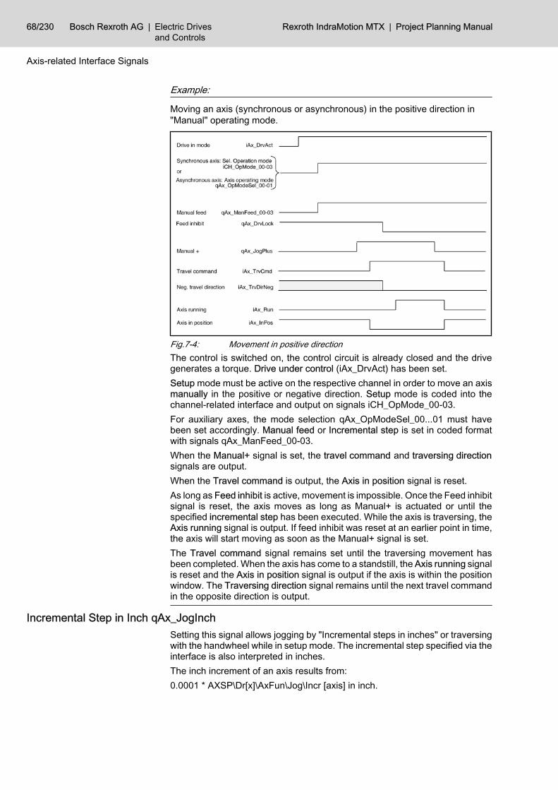
Example:
Moving an axis (synchronous or asynchronous) in the positive direction in"Manual" operating mode.
Fig.7-4: Movement in positive directionThe control is switched on, the control circuit is already closed and the drivegenerates a torque. Drive under control (iAx_DrvAct) has been set.Setup mode must be active on the respective channel in order to move an axismanually in the positive or negative direction. Setup mode is coded into thechannel-related interface and output on signals iCH_OpMode_00-03.For auxiliary axes, the mode selection qAx_OpModeSel_00...01 must havebeen set accordingly. Manual feed or Incremental step is set in coded formatwith signals qAx_ManFeed_00-03.When the Manual+ signal is set, the travel command and traversing directionsignals are output.When the Travel command is output, the Axis in position signal is reset.As long as Feed inhibit is active, movement is impossible. Once the Feed inhibitsignal is reset, the axis moves as long as Manual+ is actuated or until thespecified incremental step has been executed. While the axis is traversing, theAxis running signal is output. If feed inhibit was reset at an earlier point in time,the axis will start moving as soon as the Manual+ signal is set.The Travel command signal remains set until the traversing movement hasbeen completed. When the axis has come to a standstill, the Axis running signalis reset and the Axis in position signal is output if the axis is within the positionwindow. The Traversing direction signal remains until the next travel commandin the opposite direction is output.
Incremental Step in Inch qAx_JogInchSetting this signal allows jogging by "Incremental steps in inches" or traversingwith the handwheel while in setup mode. The incremental step specified via theinterface is also interpreted in inches.The inch increment of an axis results from:0.0001 * AXSP\Dr[x]\AxFun\Jog\Incr [axis] in inch.
68/230 Bosch Rexroth AG | Electric Drivesand Controls
Rexroth IndraMotion MTX | Project Planning Manual
Axis-related Interface Signals

Machine parameter AXSP\Dr[x]\AxFun\Jog\Incr corresponds to /AX/Dr[1]/Jog/IncrAxJog "Axis resolution" (1015 00001).
The "Incremental step in inch" interface signal is insignificant forrotary and endless axes.
Example:
AXSP\Dr[x]\AxFun\Jog\Incr = 1
1 incremental step in inches = 0.0001 inch1 incremental step in metric units = 0.001 mm
1: In jog mode or handwheel mode, the incremental step specifiedis interpreted in "inches".
0: In jog mode or handwheel mode, the incremental step specifiedis interpreted in "inches".
Incremental Step as Diameter qAx_JogDiaSetting this signal allows jogging by "incremental steps in diameter" or travers‐ing with the handwheel while in setup mode. The incremental step specified viathe interface is also interpreted as a diameter difference.The unit of measurement of the increments is specified by the signal "Incre‐mental step in inch".1: In jog or handwheel mode, the incremental step specified is
interpreted as a diameter difference.0: In jog or handwheel mode, the incremental step specified is
interpreted as a radius difference.
Next Notch Position qAx_NextNotchWith this signal, the NC can move a Hirth axis to its next grid position. For thispurpose, the NC must be in Manual set up mode and the Hirth axis must notbe activated by Jog mode at the same time (iAx_NotchPos has been set).The traversing direction which was active last (see iAx_TrvDirNeg) determinesthe direction in which the Hirth axis is moved.The signal can be used to move a Hirth axis which has come to a standstill andis located between 2 grid positions (e.g.: in case of EMERGENCY STOP) fromthe current travel direction back to the grid position.
Axis Reset qAx_ResetThis signal is used to cancel the movement of an asynchronous axis. After theaxis has come to a standstill, the signal axis is reset (iAx_Reset).0 → 1: The signal axis reset (iAx_Reset) is set.1 → 0: No effect.
Limit Switch Range 0 ... 1 qAx_TrvLim_00 ... 01Selects one of four possible limit switch ranges.
Bit combination 0: 1. Limit switch range activeBit combination 1: 2. Limit switch range activeBit combination 2: 3. Limit switch range active (not yet available)Bit combination 3: 4. Limit switch range active (not yet available)
Project Planning Manual | Rexroth IndraMotion MTX Electric Drivesand Controls
| Bosch Rexroth AG 69/230
Axis-related Interface Signals
Signal level
Signal level
Signal edge

Signal "Suppress limit switches" (qAx_SwLimOff) affects the selec‐ted limit switch range.
Suppress Limit Switches qAx_SwLimOffThis signal suppresses the positive and negative limit switches of the respectiveaxis. In this case, no position limit monitoring is active on the NC for this axis.As long as the reference point of the axis is not known (see iAx_RefKnown),this signal is not relevant. The internal checks performed by the NC are alwaysswitched off in this case.Monitoring within the drive is not affected by this signal (e.g. S-0-0049 Positionlimit value positive; S-0-0050 Position limit value negative). Other safety-rele‐vant functions must be assumed by the machine and/or PLC when the softwarelimit switches are suppressed.The Suppress limit switches signal is active in all operating modes.1: The software limit switches are suppressed.0: The software limit switches are not suppressed. The NC mon‐
itors the position limits as defined in the machine parametersin accordance with the limit switch range selected.
Cancel Fixed Stop qAx_FxStopRelSetting this signal cancels an active fixed stop for an asynchronous axis.
Mode Selection (BA) qAx_SafOpModeSwitchThis signal is a component of the safety technology for the IndraDrive series.The operating mode selection of the PLC is transferred as channel 1 to the drivevia the SERCOS interface in real time.0: Normal mode NO1: Special mode SO
(special mode at standstill / with movement)
Drive Lock qAx_SafDrvLockThis signal is a component of the safety technology for the IndraDrive series.The "Drive lock" signal is transferred as channel 1 to the drive using the PLCvia the SERCOS interface in real time. The drive releases itself from torquewhen the drive lock is selected.1: Drive lock on.0: Drive lock off.
Consent Key qAx_SafEnablCtrlThis signal is a component of the safety technology for the IndraDrive series.Switching to "Special mode with movement" via the PLC is transferred as chan‐nel 1 to the drive via the SERCOS interface in real time.1: Special mode with movement.0: Special mode at standstill.
S Switch 1 (S1) qAx_SafSwitch1These signals are components of the safety technology for the IndraDrive ser‐ies.
70/230 Bosch Rexroth AG | Electric Drivesand Controls
Rexroth IndraMotion MTX | Project Planning Manual
Axis-related Interface Signals
Signal level
Signal level
Signal level
Signal level

Two different parameter sets can be stored in the drive for "Special mode withmovement". The parameter set selected using the PLC is transferred as chan‐nel 1 to the drive via the SERCOS interface in real time.1: Parameter set 2 for safe movement active.0: Parameter set 1 for safe movement active.
Check Input Safety Technology qAx_SafCheckInputStateThis signal is a component of the safety technology for the IndraDrive series.The safe status signal set using the PLC is transferred as channel 1 to the drivevia the SERCOS interface in real time.
Status S Signals qAx_SafTechStateThis signal is a component of the safety technology for the IndraDrive series.The control signals of the PLC (qAx_Saf...) that are transferred via channel 1to the drive must be adjusted periodically so that they can be checked. As aresult, the PLC sets the signals to "0" for one cycle. At the same time, the PLCsets the safety signal status from "valid" to "adjusted", thus informing the drivethat the control signals are invalid.Then the signals are reset.1: The control signals of the safety technology are valid.0: The control signals of the safety technology are being adjusted.
Handwheel Selection Bit 0 and Bit 1 qAx_HandwSel_00 ... 01Two handwheels can be connected to the NC control. As soon as one of thetwo signals is set, the axis can be traversed with the selected handwheel. Sig‐nals Manual + and Manual - have no effect.If the axis is traversed with the handwheel, signals Manual feed 0...3 are active.In this context, the incremental steps that can be selected are used in the cal‐culation to weight the scale marks of the handwheel.
Handwheel
Handwheel assignment
Bit 1(qAx_HandwSel_01)
Bit 0(qAx_HandwSel_00)
no handwheel active 0 0
Handwheel 1 0 1
Handwheel 2 1 0
reserved 1 1
Fig.7-5: Handwheel selection, bit 0 and bit 1
Handwheel Direction qAx_HandwDirThis signal permits the direction of axis rotation to be specified, regardless ofthe direction of handwheel rotation.1: The direction of axis rotation is opposite to the direction of
handwheel rotation.0: The directions of axis and handwheel rotation are the same.
Handwheel Position qAx_HandwPosModeWith this signal it is possible to specify the behavior of handwheel mode duringexceeding the currently allowed maximum speed.
Project Planning Manual | Rexroth IndraMotion MTX Electric Drivesand Controls
| Bosch Rexroth AG 71/230
Axis-related Interface Signals
Signal level
Signal level
Signal level

The level of the signal is adopted from the NC during settingqAx_HandwSel_0x .
1: The distance specified by the handwheel movement is alsoprocessed when the maximum speed is exceeded.Note: Axis movements can also occur after exiting the hand‐wheel movement.
0: When exceeding the maximum speed, the traverse path is re‐duced accordingly.
Manual Feed for Bit 0 ... Bit 3 qAx_ManFeed_00 ... 03These signals are effective in the Setupoperating mode. If the axes are trav‐ersed manually with the jog button or handwheel, the feed rates or incrementalsteps which are assigned to the corresponding bit combination become active.The velocities will be defined in the machine parameters AXSP\Dr[x]\AxFun\Jog\Vel\...When the axes are moved using a handwheel, the incremental steps are eval‐uated as the weighting factor for the scale divisions of the handwheel.The incremental steps for x increments are specified in machine parameter /AX/Dr[1]/Jog/VarDistAxJog "Variable incremental step" (1015 00002).
Manual feed / in‐cremental step Machine parameter
Bit 3(qAx_ Man‐Feed_03)
Bit 2(qAx_ Man‐Feed_02)
Bit 1(qAx_ Man‐Feed_01)
Bit 0(qAx_ Man‐Feed_00)
no input - 0 0 0 0
Rapid traverse/AX/Dr[1]/Jog/Vel/RapidAx‐Vel "Manual feed Rapid tra‐verse" (1005 00006)
0 0 0 1
Fast/AX/Dr[1]/Jog/Vel/FastAxVel"Manual feed fast" (100500005)
0 0 1 0
Medium/AX/Dr[1]/Jog/Vel/Medium‐AxVel "Manual feedfast" (1005 00004)
0 0 1 1
Slow/AX/Dr[1]/Jog/Vel/SlowAx‐Vel "Manual feedslow" (1005 00003)
0 1 0 0
x increments/AX/Dr[1]/Jog/Vel/VarDis‐tAxVel "Manual feed for var‐iable steps" (1005 00008)
0 1 0 1
1000 increments/AX/Dr[1]/Jog/Vel/DefSte‐pAxVel "Manual feed for de‐fined steps" (1005 00007)
0 1 1 0
100 increments 0 1 1 1
10 increments 1 0 0 0
1 increment 1 0 0 1
Fig.7-6: Manual feed for bit 0 ... Bit 3 - incremental step
Axis Override 100% qAx_Override10 This signal suppresses the axis override of an asynchronous axis. In this case,the axis traverses at the preselected or programmed velocity. The signal refers
72/230 Bosch Rexroth AG | Electric Drivesand Controls
Rexroth IndraMotion MTX | Project Planning Manual
Axis-related Interface Signals
Signal level

to programmed asynchronous movements/external command value inputs aswell as to manual mode (jogging).The signal has no effect on movements interpolated by the drive (e.g. traverseto reference point).1: Axis override is suppressed.0: Axis override is active.
Override Bit 0 ... Bit 15 qAx_Override_00 ... 15The traversing speed of asynchronous axes can be influenced by the overridefunction. It affects the speeds programmed in the part program and on the pre‐selected speeds in Setup mode.This signal is used to activate one override weighting level for an auxiliary axisif the override has not been suppressed either using the interface (qAx_Over‐ride100) or the machine parameters.The levels of the override switch are queried by the NC in binary coded form.Via machine parameter /CHAN/Ch[1]/Path/Ovrd/ChOvrdStep[1], /AX/Asyn‐chrAxOvrdIf/AxOvrdStep[1] "Feed override for channel" (7030 00010), eachbinary code is assigned a value by channel 0 (!) which interprets the respectivevelocity as a percentage.
Customer Input 1 ... 8 qAx_Custom1 ... 8Interface that can be configured on the NC side and can be assigned as re‐quired.(This option is currently not yet active.)
Suppress Standstill Error qAx_TrqErrOffThis signal suppresses an internal error state when the standstill torque hasbeen exceeded. In this case, it is necessary for standstill torque monitoring tobe programmed in the PLC.
Regardless of this signal, the "Standstill error" (iAx_TrqExceed) er‐ror signal is set when the standstill torque has been exceeded!
1: If the standstill torque has been exceeded, the NC will not gen‐erate an internal error signal. Exeeding is tolerated.
0: Error status when the level drops below the standstill torque.
Suppress Coupling Error qAx_LagErrOffThis signal suppresses an internal error state when the coupling lag limit hasbeen exceeded. In this case, monitoring of the coupling lag must be program‐med in the PLC.
Regardless of this signal, the "Coupling lag" (iAx_CoupleLag) signalis set if the coupling lag limit has been exceeded!
1: In case a coupling lag limit is exceeded, the NC will not gen‐erate an internal error signal. Exeeding is tolerated.
0: Coupling lag limit monitoring generates an error.
Project Planning Manual | Rexroth IndraMotion MTX Electric Drivesand Controls
| Bosch Rexroth AG 73/230
Axis-related Interface Signals
Signal level
Signal level
Signal level

Gantry on Master Position qAx_MasterPos
CAUTION
The signal may only be set when the encoders have been commis‐sioned.Otherwise, there is the risk of mechanical damages.
In case of a Gantry slave with an absolute encoder, this signal is used to transferthe command position of the master axis without any offset as the commandposition of the slave axis. The signal effects on the slave axis.Prerequisites:● Master and slave with absolute encoder.● Difference of positions less than the maximum following error configured
in the machine parameters.● The signal effects also in incremental measuring systems with distance-
coded encoders if referencing with "Travel distance" is set.● The signal applies in following conditions:
– Drive in reference.– Maximum following error not exceeded or following error monitoring
deactivated.In case of cyclically absolute encoders, the axis positions are not known priorto referencing. This is why the distance between the gantry axes, which is de‐termined from the actual position values provided by the encoders, is main‐tained until referencing for safety reasons.In case of axes with absolute encoders, the actual position values are alsoknown without referencing. When the encoders have been commissioned, apossible skew can be recognized from the values they supply.0 → 1: The skew of the slave axis is compensated by a jerk as soon
as the drives are in operation. If the distance is too great, aservo error will occur.
Take Over Actual Value Offset qAx_TakeActOffsAcceptance of actual value displacement of this slave as command value dis‐placement.0 → 1: Acceptance of actual value displacement during open control‐
ler.The command value displacement of a Gantry slave is created from the controlof the current actual value displacement and retightened as long as the con‐troller is open. When the controller closes, the value is frozen.The signal must be set for the slave axis.
Axis Discharged qAx_DischargeWhen this signal is set, the axis is no longer checked within the Inposlogic.Nevertheless, the axis can remain in the configuration of a channel if signalDrive on has not also been set.
Hold Command Position qAx_FrzIpoPosThis signal prevents the actual drive position from being corrected with the po‐sition control loop open, i.e. "Drive under control" (iAx_DrvAct) is not set.1: The actual position of the drive is not transferred to the NC
when the position control loop is open.
74/230 Bosch Rexroth AG | Electric Drivesand Controls
Rexroth IndraMotion MTX | Project Planning Manual
Axis-related Interface Signals
Signal edge
Signal edge
Signal level

0: When the position control loop is open, the actual drive positionis input in the NC.
Torque Reduction qAx_TrqLi This signal allows the torque limit (SERCOS parameter S-0-0092) valid in thedrive to be changed.This signal is of particular significance in conjunction with the axis clampingfunction: With the axis clamped, the position control loop may remain closedwhile the torque of the drive can be reduced in order to minimize mechanicalstress. To a large extent, this prevents mechanical axis displacement whenclamping is applied or released.The value of the changed torque limit is set individually for each axis via ma‐chine parameter RedMaxTorq "Reduced maximum torque when torque reduc‐tion enabled" (1003 00010). Besides, it can be programmed via the RedTorque(RDT) NC function.A torque changeover is permissible only when the axis is at a standstill.If the torque limit is not accepted by the drive (e.g. because the parameter iswriteprotected), no error message is displayed. However, signal "Torque limi‐ted" (iAx_TrqLim) is not set.0 → 1: The torque reduction is transmitted to the drive via the SER‐
COS interface.1 →0: The original torque limit, as specified in SERCOS parameter
S-0-0092, is transmitted to the drive.
Drive on qAx_DrvOnThis signal switches the torque in the drive on when it is ready for operation(iAx_DrvReady has been set). The control circuit is closed.Resetting Drive on initiates a shutdown process. If the axis is still in motion atthis time, it is brought to a halt at the preset deceleration.When the axis has come to a standstill, the position control loop is opened andthe Drive under control signal is reset. Torque is no longer applied on the drive.
Fig.7-7: Drive onExample:
Functioning of the starting and shutdown cycles
When the machine is started or voltage is applied, the NC unit and the servoand spindle drives go through an initialization phase.While the initialization phase of the individual components is running, the digitalinterface for communication between the NC and the drives is established,among other things.This digital interface corresponds to the settings of the SERCOS interface.
Project Planning Manual | Rexroth IndraMotion MTX Electric Drivesand Controls
| Bosch Rexroth AG 75/230
Axis-related Interface Signals
Signal edge

Initialization of the SERCOS interface is in system, automatic and consists of4 phases. Once the interface is initialized and cyclic operation is active, theEnabled for power activation signal is output.Power can be switched on for the affected drives. When the power has beenconnected, the Drive ready signal is output.The position control loop is closed by setting Drive on. The drive is under torqueand the Drive under control signal is issued.The shutdown cycle or disconnection from the system is initiated by the PLCsequential program resetting the Drive on signal.If the axis is still in motion at this time, it is brought to a halt at the preset de‐celeration.When the axis has come to a standstill, the position control loop is opened andthe Drive under control signal is reset. Torque is no longer applied on the drive.The power can be switched off in the next step.The Enabled for power activation signal remains set as long as the machinecomponents (NC and drives) remain initialized.
Feed Inhibit qAx_DrvLockThis signal is effective when the control loop is closed and torque is applied onthe axis.It prevents a programmed or manually preset axis movement from being carriedout; however, it has no influence on the Travel command, Negative travel di‐rection and Axis in position input signals.1: Either the axis cannot be moved or it is stopped with the de‐
celeration set in the parameters if a movement is alreadyactive.If Feed inhibit is set for an axis which participates in an inter‐polation with other axes, the other axes cannot be traversedeither.
0: Axis feed is not inhibited. If an axis travel command is initiated(via the NC part program or manually), the axis can start tra‐versing immediately.If a traversing axis was previously brought to a standstill withFeed inhibit, it will start accelerating to its programmed speedas soon as the Feed inhibit signal is reset.
Example:
Feed lock
The machine is switched on and the control loop has been closed. A negativetraversing motion has been programmed for an axis via the NC part program.
76/230 Bosch Rexroth AG | Electric Drivesand Controls
Rexroth IndraMotion MTX | Project Planning Manual
Axis-related Interface Signals
Signal level

Fig.7-8: Drive under controlThe Drive under control signal informs the PLC sequential program that thecontrol loop is closed.The Travel command and Neg. traversing direction signals are output as soonas the NC block where the traversing motion is programmed is executed. Thetraversing direction is up-to-date only if a traversing command has been set.The Axis in position signal is reset when the travel command is activated.Traversing movement is not carried out as long as the Feed inhibit signal is set.When Feed inhibit is reset, the programmed traversing movement is performedand Axis running is set.If Feed inhibit is set again during the traversing movement, the traversingmovement is stopped and Axis running is reset when the axis has come to astandstill.When Feed inhibit is reset, the axis accelerates up to the previously appliedspeed, Axis running is set and the traversing movement is completed.When the programmed end position is reached, the Travel command and Axisrunning signals are reset and the Axis in position signal is set.
Reduce Transfer Time qAx_SafRedTransTimeThis signal is a component of the safety technology for the IndraDrive series.This signal allows the PLC to reduce the time of transfer from normal mode tospecial mode (P-0-3220) and/or from special mode to special mode (P-0-3225).Please note the remarks in the drive documentation about "status machine ofthe integrated safety technology" and about the SERCOS parameter "P-0-3212(SI control word, channel 1) Bit 11".1: Signals to the drive that the adjustment to the target value sys‐
tem has been completed and the drive will activate the moni‐toring of the selected special mode.
0: No effect.
7.2.2 Input Signals (NC → PLC) Reference Point Known iAx_RefKnown
This signal is set as soon as the reference point of the axis has been reached,or, if absolute encoders are used, as soon as they have been recognized bythe control. To do this, the control evaluates SERCOS parameter Actual posi‐tion value status S-0-0403. The NC does not monitor any limit switches as longas the Reference point known signal has not yet been set.
Project Planning Manual | Rexroth IndraMotion MTX Electric Drivesand Controls
| Bosch Rexroth AG 77/230
Axis-related Interface Signals
Signal level

After this signal has been set once, it will be reset only when a newSERCOS phase run-up has been initiated, or in the case of a drivefault (e.g. defective encoder).
1: The reference point has been reached, or the axis is equippedwith absolute encoders.
0: No reference point has been approached yet.
1 Start approaching reference point2 Approaching reference point completed3 Start approaching reference point4 Abort approaching of reference point (drive has identified reference
point)5 Control reset6 Start approaching reference point7 Approaching reference point completed8 Drive lost reference point due to a fault9 Control resetFig.7-9: Homing point
Reference Point Was Reached iAx_RefReachedIn contrast to the Reference point is known signal, this signal is set only whentraversing to the reference point has been successfully completed. If traversingto the reference point was cancelled, neither of the two signals will be set.While a subsequent basic setting causes a status check of the actual positionvalues to be performed in the drive (parameter S-0-0403) and sets (or clears)the Reference point is known signal, as applicable, the Reference point wasreached signal remains unchanged.This signal is reset at the beginning of any traverse to a reference point.1: The last traverse to the reference point was properly completed
by reaching the reference point.0: Either no reference points have been approached so far, or
traversing to the reference point is still active and the referencepoint has not yet been reached, or the last traverse to the ref‐erence point was cancelled.
Travel Command iAx_TrvCmdThe signals Travel command, Neg. traversing direction, Axis running and Axisin position affect each other.Examples of their relationships are shown in the signal diagrams and explan‐ations of signals Manual+/- (chapter "Manual+ qAx_JogPlusManual- qAx_Jog‐Minus " on page 67) and Feed inhibit (chapter "Feed Inhibit qAx_DrvLock" onpage 76).The Neg. traversing direction signal is output in conjunction with the Travelcommand signal.1: The input for a traversing movement exists. It can be carried
out by manual input or via the NC part program.0: No command for the traversing movement is present.
78/230 Bosch Rexroth AG | Electric Drivesand Controls
Rexroth IndraMotion MTX | Project Planning Manual
Axis-related Interface Signals
Signal level
Signal level
Signal level

Negative Traversing Direction iAx_TrvDirNegThis signal is effective only in conjunction with the signal Travel command. Inthe absence of a travel command signal, this signal is irrelevant.1: If "Negative traversing direction" and "Travel command" are
set, the respective axis is to execute a traversing movement inthe negative direction or the previous movement of this veryaxis was executed in the negative direction.
0: If "Negative traversing direction" is not set and "Travel com‐mand" is set, the respective axis is to execute a traversingmovement in the positive direction or the previous movementof this very axis was executed in the positive direction.
Axis Running iAx_RunThe signals Travel command, Neg. traversing direction, Axis running and Axisin position affect each other.Examples of their relationships are shown in the signal diagrams and explan‐ations of signals Manual+/- (chapter "Manual+ qAx_JogPlusManual- qAx_Jog‐Minus " on page 67) and Feed inhibit (chapter "Feed Inhibit qAx_DrvLock" onpage 76).If the traversing movement of an axis has been concluded on the NC side, notravel command is active any more, and the signals Axis in position or Axisrunning will be output.1: "Axis running" remains set for as long as the axis executes a
programmed or manually preset movement.This signal is not set in the case of drive controlled approachingof the reference point even if the axis is still in motion.
0: The axis performs no movement.
Axis in Position iAx_InPos The signal is active when the control loop is closed and torque is applied on theaxis.1: The axis is located within the in-position window set in the pa‐
rameters and no travel command is active. The inpositionwindow is specified by SERCOS parameter S-0-0057.The "In-position rough" window is specified with SERCOS pa‐rameter S-0-0261, for Diax/EcoDrive and HNC100 with themachine parameter /NCO/InPosWin/[1]/InPosRough "In-posi‐tion window" (1015 00100).
0: The axis is not in the parameterized inposition window.
Axis on Notch Position iAx_NotchPosThis signal indicates when the Hirth axis has reached a grid position.The level of this signal is 0 as long as the reference point has not been ap‐proached. This signal is set to 1 as soon as the axis is within the selected in-position window.1: The Hirth axis is within the selected in-position window.0: Indicates that the Hirth axis has not yet approached a reference
point.
Axis Reset iAx_ResetThis signal indicates that the asynchronous axis accepted the control reset taskand that the asynchronous axis is ready to accept new inputs for motions.
Project Planning Manual | Rexroth IndraMotion MTX Electric Drivesand Controls
| Bosch Rexroth AG 79/230
Axis-related Interface Signals
Signal level
Signal level
Signal level
Signal level
Axis Near End Point iAx_DistCtrlThis signal indicates that the axis is within a range before its end point definedvia machine parameter /SFU/AxDistCtrl/Dr[1]/EnablAxDistCtrl, /SFU/Ax‐DistCtrl/Dr[1]/DistEndPoint "Distance to end point" (1015 00010).1: Axis command position within the indicated distance.0: Axis command position outside of the indicated distance, not
configured, approaching reference point is active or handwheelis active.
Axis Speed Reached iAx_ProgSpReach1: The asynchronous axis reached the programmed speed or the
modulo speed <Axis>=S<Value>. The position of the overrideswitch is taken into account.
0: The speed or the modulo speed of the asynchronous axis hasnot been yet reached or the speed interpolation was cancelledwith <Axis>=S0 or an positioning process.
Fixed Stop Reached iAx_FxStopReachedThis signal is output when the axis is positioned at a fixed stop.The signal is reset when the axis leaves the 'fixed stop' monitoring window(machine parameter /MPS/Dr[1]/MaxDevPoStop "Fixed stop monitoring win‐dow" (1003 00032)), or when fixed stop has been canceled with "FsRe‐set" (FSR).1: Axis has reached the fixed stop.0: Fixed stop left or cancelled.
Fixed Stop Active iAx_FxStopActThis signal is output when the traverse movement to the fixed stop is active.A movement to the fixed stop is triggered by the "FsProbe" (FSB, Measuring atfixed stop) or "FsMove" (FSM, Move to fixed stop) functions.1: Axis moves to fixed stop.0: No move to fixed stop active.
Bit 0 Safety Mode ... Bit 3 iAx_SafOpMode_00 ... 03These signals are components of the safety technology for the IndraDrive ser‐ies.The NC reads the selected operating mode of the drive (P-0-3215) and passesthe information to the PLC via these outputs.
Safety function
Safety mode
Bit 3(iAx_ SafOpMode_00)
Bit 2(iAx_ SafOpMode_00)
Bit 1(iAx_ SafOpMode_00)
Bit 0(iAx_ SafOpMode_00)
Normal mode NO 0 0 0 0
Safe starting lockout(ASP)
0 0 0 1
Safe stop (SH) / Safemode stop (SBH)
0 0 1 0
Safe movement (SBB1) 0 0 1 1
Safe movement (SBB2) 0 1 0 0
80/230 Bosch Rexroth AG | Electric Drivesand Controls
Rexroth IndraMotion MTX | Project Planning Manual
Axis-related Interface Signals
Signal level
Signal level
Signal level
Signal level

Safety function
Safety mode
Bit 3(iAx_ SafOpMode_00)
Bit 2(iAx_ SafOpMode_00)
Bit 1(iAx_ SafOpMode_00)
Bit 0(iAx_ SafOpMode_00)
Safe movement (SBB3) 0 1 0 1
Safe movement (SBB4) 0 1 1 0
Safety technology notactive
1 1 1 0
Fig.7-10: Safety mode
Status Safe Position iAx_SafStatePosThis signal is a component of the safety technology for the IndraDrive series.The drive uses this signal to report whether safe referencing has been carriedout; this is a requirement for safety function "Safe absolute position" .1: The drive is safely referenced.0: No safe referencing.
Status Output Controller iAx_SafCtrlOutputStateThis signal is a component of the safety technology for the IndraDrive series.The drive uses this signal to provide feedback about its safe status.1: Safe status of the drive.0: No safe status of the drive.
Position Switch Point 1 ... 8 iAx_PosSwitch1 ... 8This signal serves to monitor the actual position of an axis. An axis may beassigned a maximum of 8 axis monitoring positions (electric limit switches).With machine parameter SFU\WayPoint\Point[x] (/SFU/WayPoint/Point[1]/DrIndWayPoint, /SFU/WayPoint/Point[1]/MonTypeWayPoint "Monitored ax‐is" (2010 00100), /SFU/WayPoint/Point[1]/PosWayPoint "Point position" (201000110), /SFU/WayPoint/Point[1]/IfSigWayPoint "Interface signal of thepoint" (2010 00120), /SFU/WayPoint/Point[1]/MonTypeWayPoint "Cyclic mon‐itoring of rotary axes" (2010 00130)), you can define a total of up to 64 axismonitoring positions for the whole system.By combining two signals, you can create "monitoring windows".For further information, see the "Machine Parameters" manual.1: The actual axis position is greater than or equal to the moni‐
toring position.0: The actual axis position is less than the monitoring position.
Channel Number bit 0 ... Bit 3 iAx_ChIndex_00 ... 03This signal is used to output the binary coded channel number of the corre‐sponding channel."0" is output if the axis is not assigned to any channel (e.g. asynchronous axis)
Channel numberBit 3(iAx_ ChIndex_03)
Bit 2(iAx_ ChIndex_02)
Bit 1(iAx_ ChIndex_01)
Bit 0(iAx_ ChIndex_00)
no channel 0 0 0 0
Channel 1 0 0 0 1
Project Planning Manual | Rexroth IndraMotion MTX Electric Drivesand Controls
| Bosch Rexroth AG 81/230
Axis-related Interface Signals
Signal level
Signal level
Signal level

Channel numberBit 3(iAx_ ChIndex_03)
Bit 2(iAx_ ChIndex_02)
Bit 1(iAx_ ChIndex_01)
Bit 0(iAx_ ChIndex_00)
... ... ... ... ...
Channel 12 1 1 0 0
Fig.7-11: Channel number bit 0 ... Bit 3If axes are lent to another channel, they are output in the following manner:
Status Channel information
Channel is activated (for program selec‐tion or manual data input) with one axis Number of this channel
Channel is deactivated (for program dese‐lection or end of manual data input) withone axis
Number of this channel
Channel releases axis with RemAxis; axishas not been released on its original chan‐nel
Number of the original channel
Channel releases axis with RemAxis; axishas been released on its original channel 0
Fig.7-12: Channel outputDefinitions:
Lent axis: An axis is lent if a channel accesses an "axis of an inactivechannel" while the axis was not released on this channel with"RemAxis" (RAX).
Original channel: When the NC starts up, all synchronous axes belong to anoriginal channel.
Axis Override 0% iAx_Override0This signal for an asynchronous axis indicates that its axis override is set to 0%and that no Override 100% has been selected using the interface (qAx_Over‐ride100).1: 0% acts on the axis.0: A value not equal to 0% acts on the axis.
Axis Override 100% iAx_Override100This signal for an asynchronous axis indicates that its axis override is set to100% and/or that Override 100% has been selected using the interface(qAx_Override100).1: A value of 100% acts on the axis.0: A value not equal to 100% acts on the axis.
SCS Signal Status 0 ...15 iAx_ScsState00 ... 15In the signal status word (SERCOS parameter S-0-0144), the configured bitsignals from the cyclic telegram of the axis drive are transmitted to the NC.The status signals can be configured in parameter S-0-0026. For transmissionof the signals in cyclic telegram, parameter S-0-0144 must be taken over intothe configuration list of the drive telegram (S-0-0016).
82/230 Bosch Rexroth AG | Electric Drivesand Controls
Rexroth IndraMotion MTX | Project Planning Manual
Axis-related Interface Signals
Signal level
Signal level

Example:
Configuration:
● S-0-0026 = (330, 331,0, 333, 0, 335, 336, 337, 0, 0, 0, 0, 0, 0, 0, 0):Configuration of the signal status word
● S-0-0016 = (40, 144):Configuration of the drive telegram
The following status messages are then allocated to the individual signals:● iAx_ScsState00: S-0-0330 message nact= ncom
● iAx_ScsState01: S-0-0331 message nact= 0● iAx_ScsState02: -● iAx_ScsState03: S-0-0333 message Md≥Mdx
● iAx_ScsState04: -● iAx_ScsState05: S-0-0335 message ncom>nlimit
● iAx_ScsState06: S-0-0336 message In-Position● iAx_ScsState07: S-0-0337 message P≥Px
● iAx_ScsState08: -● iAx_ScsState09: -● iAx_ScsState10: -● iAx_ScsState11: -● iAx_ScsState12: -● iAx_ScsState13: -● iAx_ScsState14: -● iAx_ScsState15: -
For a detailed description of all status messages available, pleasesee the "SERCOS interface Specifications".
Customer Output 1 ... 8 iAx_Custom1 ... 8Interface that can be configured on the NC side and can be assigned as re‐quired.(This option is currently not yet active.)
Index of Master Axis Bit 0 ... Bit 4 iAx_MasterAxindex_00 ... 04Each axis is given the axis index of its master axis in binary code; the followingapplies:● The index of the master axis must be less than 32.● If the axis is not coupled, the index of the master axis has a value of 0.● If the axis is the master itself, the index of the master axis is identical with
the axis index.
Standstill Error iAx_TrqExceedThis signal serves to monitor the standstill torque specified for an axis.
Project Planning Manual | Rexroth IndraMotion MTX Electric Drivesand Controls
| Bosch Rexroth AG 83/230
Axis-related Interface Signals
In the case of gantry axes, this signal refers to the sum total of thestandstill torque values (regardless of the sign) of all the axes of agroup of coupled axes. The signal is set only for the master axis.
1: The standstill torque specified for an axis has been exceeded.0: The standstill torque specified for an axis has not been excee‐
ded.
Coupling Lag iAx_CoupleLagThis signal serves to monitor the specified coupling lag for a group of coupledaxes.1: The maximum coupling lag specified for an axis has been ex‐
ceeded.0: The maximum coupling lag specified for an axis has not been
exceeded.
Gantry Command Value Displacement Active iAx_CmdOffsExst1: A command value displacement exists for this slave.
Compensable Gantry Command Value Displacement Exceeded iAx_CmdOffsExceed1: The compensable command value displacement is exceeded
for this slave.
Error State Class-1 iAx_DrvErrClass1This signal is a direct map of the corresponding signal in the SERCOS drivestatus word of the axis in question (the drive switches off and is interlocked).The interlock can be canceled only by the command "Reset diagnosticsclass-1", which is set automatically by the NC upon a control reset.The pending error can be evaluated manually using the SERCOS monitor orautomatically by having the PLC directly read the error.Parameter S-0 0011 comprises 2 bytes and has the following structure:
Bit 0: reserved
Bit 1: Amplifier switch off temperature S-0-0203
Bit 2: Motor switch off temperature S-0-0204
Bit 3: reserved
Bit 4: Control voltage fault
Bit 5: Feedback error (encoder, measuring system)
Bit 6: Error in electronic commutation system
Bit 7: Overcurrent
Bit 8: Overvoltage
Bit 9: Undervoltage fault
Bit 10: Phase fault in power supply
Bit 11: Excessive controller deviation S-0-0159
Bit 12: Communication Error
Bit 13: Position limit value exceeded S-0-0049
84/230 Bosch Rexroth AG | Electric Drivesand Controls
Rexroth IndraMotion MTX | Project Planning Manual
Axis-related Interface Signals
Signal level
Signal level
Signal level
Signal level

Bit 14: reserved
Bit 15: Manufacturer specific error S-0-0129
Fig.7-13: Structure of parameter S-0-0011
Change of Status Class-2 iAx_DrvChangeClass2This signal is a direct map of the corresponding signal in the SERCOS drivestatus word of the axis in question (switch off prewarning). The bit is set whendiagnostic class 2 is modified and is reset after reading the status via parameterS-0-0012. Reading can be carried out manually using the SERCOS monitor ordirectly by the PLC.Parameter S-0-0012 comprises 2 bytes and contains the following warnings:
Bit 0: reserved
Bit 1: Amplifier overtemperature warning S-0-0311
Bit 2: Motor overtemperature warning S-0-0312
Bit 3: reserved
Bit 4: reserved
Bit 5: reserved
Bit 6: reserved
Bit 7: reserved
Bit 8: reserved
Bit 9: reserved
Bit 10: reserved
Bit 11: reserved
Bit 12: reserved
Bit 13: reserved
Bit 14: reserved
Bit 15: Manufacturer specific warning S-0-0181
Fig.7-14: Warning parameter S-0-0012The effect of switch off prewarnings concerning the alteration bit can be sup‐pressed on the screen for diagnostics class 2 (S-0-0097).
Change of Status Class-3 iAx_DrvChangeClass3This signal is a direct map of the corresponding signal in the SERCOS drivestatus word of the axis in question (operating status messages). The bit is setwhen diagnostic class 3 is modified and is reset after reading the status viaparameter S-0-0013. Reading can be carried out manually using the SERCOSmonitor or directly by the PLC.Parameter S-0-0013 comprises 2 bytes and contains the following messages:
Bit 0: nact= ncomm S-0-0330
Bit 1: nact = 0 S-0-0331
Bit 2: ¦nact¦<¦nx¦ S-0-0332
Bit 3: ¦Md¦≥¦Mdx¦ S-0-0333
Bit 4: ¦Md¦≥¦Mdlimit¦ S-0-0334
Project Planning Manual | Rexroth IndraMotion MTX Electric Drivesand Controls
| Bosch Rexroth AG 85/230
Axis-related Interface Signals

Bit 5: ¦ncom¦>¦nlimit¦ S-0-0335
Bit 6: In-position S-0-0336
Bit 7: ¦P¦≥¦Px¦ S-0-0337
Bit 8: -
Bit 9: ¦nact¦≥min. spindle speed S-0-0339
Bit 10: ¦nact¦≥max. spindle speed S-0-0340
Bit 11: In-position rough S-0-0341
Bit 12: Target position reached S-0-0342
Bit 13: Interpolator halted S-0-0343
Bit 14: -
Bit 15: Manufacturer specific operating states S-0-0182
Fig.7-15: Messages parameter S-0-0013The effect of operating states concerning the alteration bit can be suppressedon the screen for diagnostics class 3 (S-0-0098).
Torque Reduced iAx_TrqLimThis signal indicates that the axis concerned is running at a reduced maximumtorque.1: Maximum torque of the axis is reduced.0: Maximum torque of the axis is not reduced.
Test Mode iAx_DryRunThis signal is set when the axis is in Test mode.In test mode, an axis is still interpolated internally; however, the calculatedcommand values are only shown on the display and not transmitted to the drive.The axis is held in the same position where it was when test mode was activa‐ted.Test mode can be activated using a softkey, automatically for drives that arenot connected (no SERCOS ring present) or using machine parameter 100100010 /MAIN/Dr[1]/EnablVirtMode "Virtual drive".
Enabled for Power Activation iAx_DrvPowerThis signal is closely related to the signals Drive on, Drive ready and Drive undercontrol (see S -0-0135, bit 14/15).The functional relationship is set out in detail in the signal diagram for the Driveon signal (chapter "Drive on qAx_DrvOn" on page 75).1: Initialization of the SERCOS interface, the drive and the
NCcontrol are complete and no errors are present. This signalis a prerequisite for connecting the drive to power.
0: Power cannot be connected to the drive.
Drive Ready iAx_DrvReadyThis signal is closely related to the signals Drive on, Enabled for power activa‐tion and Drive under control (see S -0-0135, bit 14/15).The functional relationship is set out in detail in the signal diagram for the Driveon signal (chapter "Drive on qAx_DrvOn" on page 75).
86/230 Bosch Rexroth AG | Electric Drivesand Controls
Rexroth IndraMotion MTX | Project Planning Manual
Axis-related Interface Signals
Signal level
Signal level

1: Power is connected to the affected drive. The signal remainsset until the drive is cut out.
0: The power is not connected to the drive.
Drive in OperationAx_DrvActThis signal is closely related to the signals Drive on,Enabled for power activa‐tion and Drive ready (see S -0-0135, bit 14/15).The functional relationship is set out in detail in the signal diagram for the Driveon signal (chapter "Drive on qAx_DrvOn" on page 75).1: The control loop remains closed and torque is applied on the
drive. The axis can be moved unless it is locked by any otherfunction, e.g. Feed inhibit.
0: The control loop is open and no torque is applied on the drive.
Project Planning Manual | Rexroth IndraMotion MTX Electric Drivesand Controls
| Bosch Rexroth AG 87/230
Axis-related Interface Signals
Signal level
Signal level

Bosch Rexroth AG | Electric Drivesand Controls
Rexroth IndraMotion MTX | Project Planning Manual

8 Spindle-related Interface Signals8.1 Overview of Spindle-related Interface Signals8.1.1 General
Spindle-related interface signals have an effect on those NC functions that arerelated to the control of a machining spindle.An interface is available for each projected spindle, i.e. for n spindles, the spin‐dle-related interface is also mapped n times on the corresponding marker.In the case of spindles assigned to a channel, the channel-related interface isalso of importance.The following description refers to the interface signals for one axis.
8.1.2 Overview of Output Signals (PLC -> NC) Bit Symbol. Addr. PLC output signal Bit Symbol. Addr. PLC output signal
0.0 qSp_CAxOn C axis on 1.0 qSp_TurnCW Spindle M3 manual
0.1 qSp_CAxOff C-axis Off 1.1 qSp_TurnCCW Spindle M4 manual
0.2 qSp_JogPlus Spindle jog M3 1.2 qSp_Stop Spindle M5 manual
0.3 qSp_JogMinus Spindle jog M4 1.3 qSp_Orientate Spindle M19 manual
0.4 - res. 1.4 - res.
0.5 - res. 1.5 - res.
0.6 - res. 1.6 - res.
0.7 qSp_Reset Spindle reset 1.7 - res.
2.0 qSp_SafOpModeSel Mode selection (BA) 3.0 qSp_Gear1Act Acknowledgement GTS1
2.1 - res. 3.1 qSp_Gear2Act Acknowledgement GTS2
2.2 qSp_SafAgreeButton Consent key 3.2 qSp_Gear3Act Acknowledgement GTS3
2.3 qSp_SafSwitch1 S switch 1 (S1) 3.3 qSp_Gear4Act Acknowledgement GTS4
2.4 - res. 3.4 - res.
2.5qSp_SafCheckInputState
Check input safetytechnology 3.5 - res.
2.6 qSp_SafSignalState Status S signals 3.6 - res.
2.7 - res. 3.7 qSp_GearIdleAct Idling acknowledge‐ment
4.0 qSp_ManSpeed_00 Spindle speed jog bit 0 5.0 qSp_SpeedLimit Speed limit
4.1 qSp_ManSpeed_01 Spindle speed jog bit 1 5.1 - res.
4.2 qSp_ManSpeed_02 Spindle speed jog bit 2 5.2 - res.
4.3 - res. 5.3 - res.
4.4 - res. 5.4 - res.
4.5 - res. 5.5 - res.
Project Planning Manual | Rexroth IndraMotion MTX Electric Drivesand Controls
| Bosch Rexroth AG 89/230
Spindle-related Interface Signals

Bit Symbol. Addr. PLC output signal Bit Symbol. Addr. PLC output signal
4.6 - res. 5.6 - res.
4.7 - res. 5.7 qSp_Override100 Spindle override 100%
6.0 qSp_Override_00 Override bit 0 7.0 qSp_Override_08 Override bit 8
6.1 qSp_Override_01 Override bit 1 7.1 qSp_Override_09 Override bit 9
6.2 qSp_Override_02 Override bit 2 7.2 qSp_Override_10 Override bit 10
6.3 qSp_Override_03 Override bit 3 7.3 qSp_Override_11 Override bit 11
6.4 qSp_Override_04 Override bit 4 7.4 qSp_Override_12 Override bit 12
6.5 qSp_Override_05 Override bit 5 7.5 qSp_Override_13 Override bit 13
6.6 qSp_Override_06 Override bit 6 7.6 qSp_Override_14 Override bit 14
6.7 qSp_Override_07 Override bit 7 7.7 qSp_Override_15 Override bit 15
8.0 qSp_Custom1 Customer input 1 9.0 - res.
8.1 qSp_Custom2 Customer input 2 9.1 - res.
8.2 qSp_Custom3 Customer input 3 9.2 - res.
8.3 qSp_Custom4 Customer input 4 9.3 - res.
8.4 qSp_Custom5 Customer input 5 9.4 - res.
8.5 qSp_Custom6 Customer input 6 9.5 - res.
8.6 qSp_Custom7 Customer input 7 9.6 - res.
8.7 qSp_Custom8 Customer input 8 9.7 - res.
10.0 - res. 11.0 - res.
10.1 - res. 11.1 - res.
10.2 - res. 11.2 - res.
10.3 - res. 11.3 - res.
10.4 - res. 11.4 - res.
10.5 - res. 11.5 - res.
10.6 - res. 11.6 qSp_DrvOn Drive on
10.7 - res. 11.7 qSp_DrvLock Spindle lock
Fig.8-1: Overview of output signals (PLC → NC)
8.1.3 Overview of Input Signals (PLC -> NC) Bit Symbol. Addr. PLC input signal Bit Symbol. Addr. PLC input signal
0.0 iSp_CAxAct C-axis is active 1.0 iSp_ProgSpReach Speed reached
0.1 iSp_CAxSwitch C axis switching 1.1 iSp_SpLim Speed limited
0.2 iSp_TurnCmd Spindle command 1.2 iSp_Stop Spindle still
0.3 iSp_TurnDirM4 Direction of rotation M4 1.3 iSp_OrientateFinish Spindle orientatet
0.4 - res. 1.4 iSp_OrientateAct Spindle orientation ac‐tive
0.5 iSp_InPos Spindle in position 1.5 - res.
0.6 iSp_PosCtrl Position control active 1.6 - res.
0.7 iSp_Reset Spindle reset 1.7 - res.
90/230 Bosch Rexroth AG | Electric Drivesand Controls
Rexroth IndraMotion MTX | Project Planning Manual
Spindle-related Interface Signals
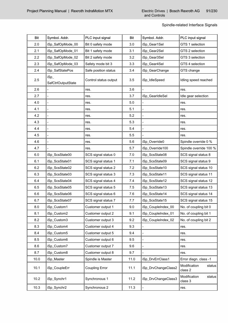
Bit Symbol. Addr. PLC input signal Bit Symbol. Addr. PLC input signal
2.0 iSp_SafOpMode_00 Bit 0 safety mode 3.0 iSp_Gear1Sel GTS 1 selection
2.1 iSp_SafOpMode_01 Bit 1 safety mode 3.1 iSp_Gear2Sel GTS 2 selection
2.2 iSp_SafOpMode_02 Bit 2 safety mode 3.2 iSp_Gear3Sel GTS 3 selection
2.3 iSp_SafOpMode_03 Safety mode bit 3 3.3 iSp_Gear4Sel GTS 4 selection
2.4 iSp_SafStatePos Safe position status 3.4 iSp_GearChange GTS change
2.5iSp_SafCtrlOutputState
Control status output 3.5 iSp_IdleSpeed Idling speed reached
2.6 - res. 3.6 - res.
2.7 - res. 3.7 iSp_GearIdleSel Idle gear selection
4.0 - res. 5.0 - res.
4.1 - res. 5.1 - res.
4.2 - res. 5.2 - res.
4.3 - res. 5.3 - res.
4.4 - res. 5.4 - res.
4.5 - res. 5.5 - res.
4.6 - res. 5.6 iSp_Override0 Spindle override 0 %
4.7 - res. 5.7 iSp_Override100 Spindle override 100 %
6.0 iSp_ScsState00 SCS signal status 0 7.0 iSp_ScsState08 SCS signal status 8
6.1 iSp_ScsState01 SCS signal status 1 7.1 iSp_ScsState09 SCS signal status 9
6.2 iSp_ScsState02 SCS signal status 2 7.2 iSp_ScsState10 SCS signal status 10
6.3 iSp_ScsState03 SCS signal status 3 7.3 iSp_ScsState11 SCS signal status 11
6.4 iSp_ScsState04 SCS signal status 4 7.4 iSp_ScsState12 SCS signal status 12
6.5 iSp_ScsState05 SCS signal status 5 7.5 iSp_ScsState13 SCS signal status 13
6.6 iSp_ScsState06 SCS signal status 6 7.6 iSp_ScsState14 SCS signal status 14
6.7 iSp_ScsState07 SCS signal status 7 7.7 iSp_ScsState15 SCS signal status 15
8.0 iSp_Custom1 Customer output 1 9.0 iSp_CoupleIndex_00 No. of coupling bit 0
8.1 iSp_Custom2 Customer output 2 9.1 iSp_CoupleIndex_01 No. of coupling bit 1
8.2 iSp_Custom3 Customer output 3 9.2 iSp_CoupleIndex_02 No. of coupling bit 2
8.3 iSp_Custom4 Customer output 4 9.3 - res.
8.4 iSp_Custom5 Customer output 5 9.4 - res.
8.5 iSp_Custom6 Customer output 6 9.5 - res.
8.6 iSp_Custom7 Customer output 7 9.6 - res.
8.7 iSp_Custom8 Customer output 8 9.7 - res.
10.0 iSp_Master Spindle is Master 11.0 iSp_DrvErrClass1 Error diagn. class -1
10.1 iSp_CoupleErr Coupling Error 11.1 iSp_DrvChangeClass2 Modification statusclass 2
10.2 iSp_Synchr1 Synchronous 1 11.2 iSp_DrvChangeClass3 Modification statusclass 3
10.3 iSp_Synchr2 Synchronous 2 11.3 - res.
Project Planning Manual | Rexroth IndraMotion MTX Electric Drivesand Controls
| Bosch Rexroth AG 91/230
Spindle-related Interface Signals

Bit Symbol. Addr. PLC input signal Bit Symbol. Addr. PLC input signal
10.4 - res. 11.4 iSp_DryRun Test mode
10.5 - res. 11.5 iSp_DrvPower Enabled for power acti‐vation
10.6 - res. 11.6 iSp_DrvReady Drive ready
10.7 - res. 11.7 iSp_DrvAct Drive under control
Fig.8-2: Overview of input signals (NC -> PLC)
8.2 Signal Description8.2.1 Output Signals (PLC-> NC) General
Depending on their function, the IndraMotion MTX evaluates the signals aseither static signals with signal levels logic 0 and logic 1 or as edge triggeredsignals with signal edges 0 -> 1 or 1 -> 0.
C-Axis on qSp_CAxOnWith this signal, the PLC can switch a spindle to C-axis operation.Application:In special cases (spindle/tool turret), it may be necessary to switch on C-axisoperation immediately after starting the control.0 → 1: The running spindle is decelerated and switched to C-axis op‐
eration.The NC-internal switching process is affected by the settingsin the machine parameter /SP/SpFunc/Sp[1]/SpTurrAx/Meas‐SysSpTurrAx "C axis: tool turret " (1040 00060).
C-Axis off qSp_CAxOffWith this signal, the PLC can switch a spindle back to spindle operation.0 → 1: The drive is switched back to spindle mode.
The NC-internal switching process is affected by the settingsin the machine parameter /SP/SpFunc/Sp[1]/SpTurrAx/Meas‐SysSpTurrAx "C axis: tool turret " (1040 00060).
1 → 0: No function.
Spindle Jog M3 qSp_JogPlusSpindle jog M4 qSp_JogMinusThese signals have an effect in NC mode Setup; their functions work togetherwith the coded signals Jog speed bit 0 ... bit 2.1: Speed specification using the coded Jog speed bit 0 ... bit 2
signals is required. Furthermore, the control loop must beclosed (Drive under control is set), spindle inhibit must be resetand a gear range must be activated. As long as the Spindle jogM3 or Spindle jog M4 signal is set, the spindle rotates at therespective speed in the selected direction of rotation.
0: The spindle is decelerated until it comes to a standstill; thecontrol loop remains closed.
92/230 Bosch Rexroth AG | Electric Drivesand Controls
Rexroth IndraMotion MTX | Project Planning Manual
Spindle-related Interface Signals
Signal edge
Signal edge
Signal level
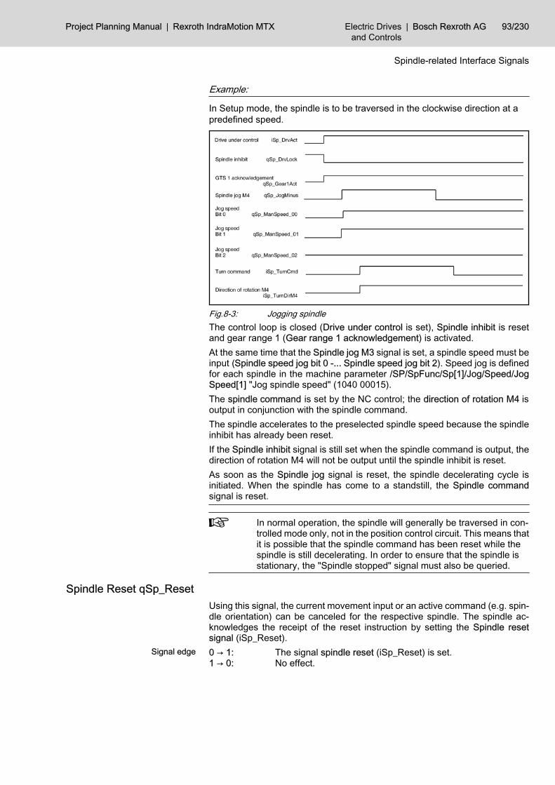
Example:
In Setup mode, the spindle is to be traversed in the clockwise direction at apredefined speed.
Fig.8-3: Jogging spindleThe control loop is closed (Drive under control is set), Spindle inhibit is resetand gear range 1 (Gear range 1 acknowledgement) is activated.At the same time that the Spindle jog M3 signal is set, a spindle speed must beinput (Spindle speed jog bit 0 -... Spindle speed jog bit 2). Speed jog is definedfor each spindle in the machine parameter /SP/SpFunc/Sp[1]/Jog/Speed/JogSpeed[1] "Jog spindle speed" (1040 00015).The spindle command is set by the NC control; the direction of rotation M4 isoutput in conjunction with the spindle command.The spindle accelerates to the preselected spindle speed because the spindleinhibit has already been reset.If the Spindle inhibit signal is still set when the spindle command is output, thedirection of rotation M4 will not be output until the spindle inhibit is reset.As soon as the Spindle jog signal is reset, the spindle decelerating cycle isinitiated. When the spindle has come to a standstill, the Spindle commandsignal is reset.
In normal operation, the spindle will generally be traversed in con‐trolled mode only, not in the position control circuit. This means thatit is possible that the spindle command has been reset while thespindle is still decelerating. In order to ensure that the spindle isstationary, the "Spindle stopped" signal must also be queried.
Spindle Reset qSp_ResetUsing this signal, the current movement input or an active command (e.g. spin‐dle orientation) can be canceled for the respective spindle. The spindle ac‐knowledges the receipt of the reset instruction by setting the Spindle resetsignal (iSp_Reset).0 → 1: The signal spindle reset (iSp_Reset) is set.1 → 0: No effect.
Project Planning Manual | Rexroth IndraMotion MTX Electric Drivesand Controls
| Bosch Rexroth AG 93/230
Spindle-related Interface Signals
Signal edge

Spindle M3 Manual qSp_TurnCWSpindle M4 manual qSp_TurnCCW Alternatively to the NC part program (programming M3, M4), these signals areused to determine the sense of rotation of the spindle:● Spindle M3 manual:
Spindle clockwise rotation● Spindle M4 manual:
Spindle anticlockwise rotation.In this regard, signal Spindle M5 manual also has significance (see the examplechapter "Spindle M5 Manual qSp_Stop" on page 94).0 → 1: Using this edge, a spindle speed and the corresponding sense
of rotation is input for the spindle drive. The spindle will start torotate if the control loop is closed ( Drive under control) and noSpindle inhibit signal is set.The spindle speed corresponds to the speed programmed last.
1 → 0: No effect.
Spindle M5 Manual qSp_StopAlternatively to the NC part program (programming M5), this signal is used toactivate the spindle stop function.In this regard, signals Spindle M3 manual and Spindle M4 manual are alsosignificant.0 →1: The spindle stops with the parameterized deceleration. The
gear range and spindle speed that were active previously re‐main stored in the NC. The control loop remains closed andtorque is still applied on the spindle drive.
1 → 0: No effect.Example:
The spindle is to be accelerated manually in the counterclockwise direction upto the speed that was programmed last.
Fig.8-4: Spindle M5 manualThe Drive under control signal indicates that the control loop is closed and tor‐que is applied on the spindle.When the Spindle M4 manual signal is set, the speed programmed last istransmitted to the spindle drive.As a result of this speed input, the NC sets the Spindle command and Directionof rotation M4 signals.When the Spindle command signal is output, the Spindle M4 manual signal canbe reset. The spindle does not rotate while Spindle inhibit is set.
94/230 Bosch Rexroth AG | Electric Drivesand Controls
Rexroth IndraMotion MTX | Project Planning Manual
Spindle-related Interface Signals
Signal edge
Signal edge

Only when the Spindle inhibit signal has been reset will the spindle start rotatingand the Spindle rotating signal be set. By setting the Spindle M5 manual signal,the rotation of the spindle is stopped and the Spindle command and Directionof rotation M4 signals are reset by the NC.
Spindle M19 Manual qSp_OrientateAlternatively to the NC part program (M19), this signal calls up the "Spindleorientation" function. For this purpose, the control loop must be closed and thedrive under control.In this regard, signals Spindle in position, Spindle orientation active and Spindleorientated have significance.
This function is not available for analog spindles (machine param‐eter /SP/SpFunc/Sp[1]/Base/SpType "Spindle type selec‐tion" (1040 00001)).
0 →1: Spindle orientation is initiated. The position results from thecurrent content of the system state SysSpCmdData[n]/Pecor‐inos. The direction of rotation depends on SERCOS parameterS-0-0154.
1 → 0: No effect.Example:
The spindle is to be oriented manually; the control loop is closed.
Fig.8-5: Spindle M19 manualThe control loop is closed (Drive under control is set) and Spindle inhibit is reset.When the signal Spindle orientation manual is set, the spindle receives thecommand to rotate; Spindle command is set.Depending on the direction of rotation, Direction of rotation M4 is set when thespindle is rotating counterclockwise (M4).When the Spindle command signal is output, the Spindle orientation manualsignal can be reset.When the spindle is rotating, Spindle orientation active is set.Once the spindle has been oriented in line with the marker position, signalsSpindle orientated and Spindle in positionare set and the Spindle commandsignal is reset.
Project Planning Manual | Rexroth IndraMotion MTX Electric Drivesand Controls
| Bosch Rexroth AG 95/230
Spindle-related Interface Signals
Signal edge

Mode Selection (BA) qSp_SafModeSelThis signal is a component of the safety technology for the IndraDrive series.The operating mode selection of the PLC is transferred as channel 1 to the drivevia the SERCOS interface in real time.1: Normal mode NO0: Special mode SO
(special mode at standstill / with movement)
Consent Key qSp_SafAgreeButtonThis signal is a component of the safety technology for the IndraDrive series.Switching to "Special mode with movement" via the PLC is transferred as chan‐nel 1 to the drive via the SERCOS interface in real time.1: Special mode with movement0: Special mode at standstill
S Switch 1 (S1) qSp_SafSwitch1These signals are components of the safety technology for the IndraDrive ser‐ies.Two different parameter sets can be stored in the drive for "Special mode withmovement". The parameter set selected using the PLC is transferred as chan‐nel 1 to the drive via the SERCOS interface in real time.1: Parameter set 2 for safe movement active.0: Parameter set 1 for safe movement active.
Check Input Safety State qSp_SafCheckInputState This signal is a component of the safety technology for the IndraDrive series.The safe status signal set using the PLC is transferred as channel 1 to the drivevia the SERCOS interface in real time.
State S Signals qSp_SafSignalStateThis signal is a component of the safety technology for the IndraDrive series.The control signals of the PLC (qAx_Saf...) that are transferred via channel 1to the drive must be adjusted periodically so that they can be checked. As aresult, the PLC sets the signals to "0" for one cycle. At the same time, the PLCsets the safety signal status from "valid" to "adjusted", thus informing the drivethat the control signals are invalid.Then the signals are reset.1: The control signals of the safety technology are being adjusted.0: The control signals of the safety technology are valid.
GTS 1 - 4 Acknowledgement qSp_Gear1Act ... 4ActIdle gear acknowledgment qSp_GearI‐dleAct
The current gear range is reported using these signals. In the case of a gearrange inconsistency, "idling" mode is activated when the next spindle commandis output.At control startup, the acknowledged gear range is adopted in the NC.For analog spindles (/SP/SpFunc/Sp[1]/Base/SpType "Spindle type selec‐tion" (1040 00001)), gear range switching is not supported. In the case of analogspindles, GTS 1 must be acknowledged.
96/230 Bosch Rexroth AG | Electric Drivesand Controls
Rexroth IndraMotion MTX | Project Planning Manual
Spindle-related Interface Signals
Signal level
Signal level
Signal level
Signal level
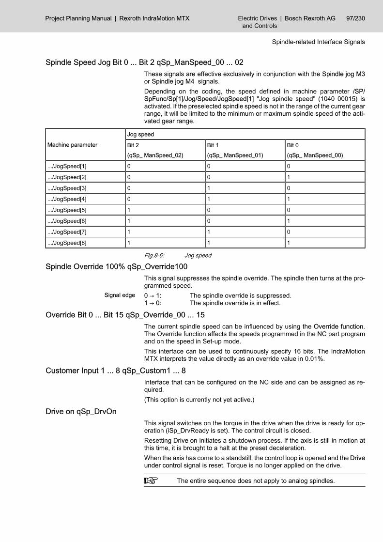
Spindle Speed Jog Bit 0 ... Bit 2 qSp_ManSpeed_00 ... 02These signals are effective exclusively in conjunction with the Spindle jog M3or Spindle jog M4 signals.Depending on the coding, the speed defined in machine parameter /SP/SpFunc/Sp[1]/Jog/Speed/JogSpeed[1] "Jog spindle speed" (1040 00015) isactivated. If the preselected spindle speed is not in the range of the current gearrange, it will be limited to the minimum or maximum spindle speed of the acti‐vated gear range.
Machine parameter
Jog speed
Bit 2(qSp_ ManSpeed_02)
Bit 1(qSp_ ManSpeed_01)
Bit 0(qSp_ ManSpeed_00)
.../JogSpeed[1] 0 0 0
.../JogSpeed[2] 0 0 1
.../JogSpeed[3] 0 1 0
.../JogSpeed[4] 0 1 1
.../JogSpeed[5] 1 0 0
.../JogSpeed[6] 1 0 1
.../JogSpeed[7] 1 1 0
.../JogSpeed[8] 1 1 1
Fig.8-6: Jog speed
Spindle Override 100% qSp_Override100This signal suppresses the spindle override. The spindle then turns at the pro‐grammed speed.0 → 1: The spindle override is suppressed.1 → 0: The spindle override is in effect.
Override Bit 0 ... Bit 15 qSp_Override_00 ... 15The current spindle speed can be influenced by using the Override function.The Override function affects the speeds programmed in the NC part programand on the speed in Set-up mode.This interface can be used to continuously specify 16 bits. The IndraMotionMTX interprets the value directly as an override value in 0.01%.
Customer Input 1 ... 8 qSp_Custom1 ... 8Interface that can be configured on the NC side and can be assigned as re‐quired.(This option is currently not yet active.)
Drive on qSp_DrvOnThis signal switches on the torque in the drive when the drive is ready for op‐eration (iSp_DrvReady is set). The control circuit is closed.Resetting Drive on initiates a shutdown process. If the axis is still in motion atthis time, it is brought to a halt at the preset deceleration.When the axis has come to a standstill, the control loop is opened and the Driveunder control signal is reset. Torque is no longer applied on the drive.
The entire sequence does not apply to analog spindles.
Project Planning Manual | Rexroth IndraMotion MTX Electric Drivesand Controls
| Bosch Rexroth AG 97/230
Spindle-related Interface Signals
Signal edge

Fig.8-7: Drive onExample:
Functioning of the starting and shutdown cycles
When the machine is started or voltage is applied, the NC unit and the servoand spindle drives go through an initialization phase.While the initialization phase of the individual components is running, the digitalinterface for communication between the NC and the drives is established,among other things.This digital interface corresponds to the settings of the SERCOS interface.Initialization of the SERCOS interface is in system, automatic and consists of4 phases. Once the interface is initialized and cyclic operation is active, theEnabled for power activation signal is output.Power can be switched on for the affected drives. When the power has beenconnected, the Drive ready signal is output.The position control loop is closed by setting Drive on. The drive is under torqueand the Drive under control signal is issued.The shutdown cycle or disconnection from the system is initiated by the PLCsequential program resetting the Drive on signal.If the axis is still in motion at this time, it is brought to a halt at the preset de‐celeration.When the axis has come to a standstill, the position control loop is opened andthe Drive under control signal is reset. Torque is no longer applied on the drive.The power can be switched off in the next step.The Enabled for power activation signal remains set as long as the machinecomponents (NC and drives) remain initialized.
Spindle Inhibit qSp_DrvLockThis signal is effective in any mode when the control loop is closed and torqueis applied to the spindle.It prevents the execution of a programmed or manually entered spindle move‐ment. If Spindle inhibit is set, the idling speed is not carried out.The signals Spindle command, Direction of rotation M4 and Spindle in positionare not affected.1: The spindle cannot be turned. If a rotating movement is already
active, the spindle will be stopped at the parameterized decel‐eration.
0: Spindle rotation is not inhibited. If a spindle command is initi‐ated (via the NC part program or manually) and the appropriategear range is active, the spindle can start rotating immediately.If a rotating spindle was brought to a standstill with Spindle in‐hibit, this spindle will now start accelerating to the initial speed.
98/230 Bosch Rexroth AG | Electric Drivesand Controls
Rexroth IndraMotion MTX | Project Planning Manual
Spindle-related Interface Signals
Signal level

Example:
Spindle lock
The machine is switched on and the control loop has been closed. A rotarymotion, e.g. M3 S1000, has been programmed via the NC part program.
Fig.8-8: Spindle lockThe Drive under control signal informs the PLC sequential program that thecontrol loop is closed. When the NC block in which the rotary movement wasprogrammed is executed, the Spindle command signal is output.As long as Spindle inhibit is set, the rotary movement will not be carried out;signal Direction of rotation M4 is not set and signal Spindle stopped is set. Thedirection of rotation can be queried only if a spindle command has been set.When Spindle inhibit is reset, the programmed rotary movement is executed,the Direction of rotation M4 is set according to the movement and Spindle stop‐ped is reset.If Spindle inhibit is set again during the rotary movement, the rotary movementis stopped and Spindle stopped is set when the spindle has come to a standstill.When Spindle inhibit is reset, the spindle accelerates to the previously appliedspeed and Spindle stopped is reset.The Spindle command signal is reset when the spindle is stopped with theM5 spindle stop function (NC part program or interface signal).
Speed Limitation SD qSp_SpeedLimitWith this signal, the PLC activates the speed limitation entered in the systemdata /SysSpCmdData[n]/MinSpeedLimit and /SysSpCmdData[n]/MaxSpeedLi‐mit.0 → 1: Applies the current content of system data and activates the
speed limitation.1 → 0: The speed limitation is switched off.
Reduce Transfer Time qSp_SafRedTransTimeThis signal is a component of the safety technology for the IndraDrive series.This signal allows the PLC to reduce the time of transfer from normal mode tospecial mode (P-0-3220) and/or from special mode to special mode (P-0-3225).Please note the remarks in the drive documentation about "status machine ofthe integrated safety technology" and about the SERCOS parameter "P-0-3212(SI control word, channel 1) Bit 11".1: Signals to the drive that the adjustment to the target value sys‐
tem has been completed and the drive will activate the moni‐toring of the selected special mode.
0: No effect.
Project Planning Manual | Rexroth IndraMotion MTX Electric Drivesand Controls
| Bosch Rexroth AG 99/230
Spindle-related Interface Signals
Signal edge
Signal level
S Value Specification via SD qSp_SValueSDThis signal permits the spindle S value specification via the system data /SysSpCmdData[n]/Speed und /SysSpCmdData[n]/OriPos.In case of the set interface signal "qSp_SValueSD" the following restrictions inthe spindle functionality result:● G96 does not work!
The combination G96 and "Speed specification via" causes a runtime er‐ror!
● M40 does not work!Only speed values programmed in the channel cause an automatic gearchange.
● SD(205,2,x) (programmed spindle speed) provides always the latest pro‐grammed value in the parts program.
1: The content of the system data SysSpCmdData[n]/Speed isused as speed value.The content of the system data SysSpCmdData[n]/OriPos isused as oriented stop position.
0: The S values given in the parts program are effective.
8.2.2 Input Signal (NC -> PLC) C-axis Active iSp_CAxAct
This signal indicates whether the respective spindle is in C-axis mode (positioninterface) or in spindle mode (speed interface). Spindles which can be switchedover to C-axis operation have additionally to the spindle interface a normal axisinterface for C-axis operation. The C-axis active signal indicates the relevantinterface.1: The spindle is in C-axis mode: the axis interface is valid, the
spindle interface is not served by the NC.0: The spindle is in spindle mode: the spindle interface is served
by the NC, the axis interface is not valid.
C-axis Switching iSp_CAxSwitchThis signal indicates that the spindle is currently in the switching phase betweenSpindle and C-axis operation.The Spindle command signal is always output at the same time.1: The spindle is in the switching phase.0: The spindle is not in the switching phase.
Turn Command iSp_TurnCmdThe Spindle command, Direction of rotation M4, Spindle stopped and Spindlein position signals affect each other mutually.Examples of their relationships are shown in the signal diagrams and explan‐ations for the Spindle M3 manual, Spindle M4 manual, Spindle M5 manual (seechapter "Spindle M3 Manual qSp_TurnCWSpindle M4 manual qSp_TurnCCW" on page 94) and Spindle inhibit (see chapter "Spindle Inhibit qSp_DrvLock"on page 98) signals.The Direction of rotation M4 signal is output in conjunction with the Spindlecommand.1: The spindle is to carry out a rotary motion, which is input either
manually (e.g. Spindle M3 manual) or via the NC part program
100/230 Bosch Rexroth AG | Electric Drivesand Controls
Rexroth IndraMotion MTX | Project Planning Manual
Spindle-related Interface Signals
Signal level
Signal level
Signal level
Signal level

(e.g. M3 S1500). A prerequisite is that the control loop isclosed, i.e. the Drive under control signal must have been set.
0: Spindle rotation was stopped by a programmed M5 spindlestop function or by a Spindle M5 manual signal (qSp_Stop).In addition, the Spindle command signal is not set if Spindleorientation, Positioning Gear range switching is active.
Direction of Rotation M4 iSp_TurnDirM4This signal is effective only in conjunction with the Spindle command signal, i.e.the Direction of rotation M4 and Spindle command signals must be linked byan AND element in the PLC sequential program.In the absence of a spindle command signal, the Direction of rotation M4 signalis irrelevant.No Direction of rotation M4 signal is output or its status remains unchanged forthe functions "Gear range switching", "Idling speed" and "Spindle orientation".1: When Direction of rotation M4 and Spindle command are set,
the spindle should carry out a rotary movement in the counter‐clockwise direction (M4).
0: When Direction of rotation M4 not set and Spindle commandis set, the spindle should carry out a rotary movement in theclockwise direction (M3).
Spindle in Position iSp_InPosThis signal is relevant only in conjunction with the Spindle orientation or Spindlepositioning functions.Requirement: The control loop is closed and torque is applied to the spindle
(signal Drive under control is set).1: The spindle has been orientated or positioned and is located
in the in-position window that is defined in the drive.0: The spindle has not been oriented and/or is not located in the
parameterized inposition window.
Position Control Active iSp_PosCtrl1: The spindle is activated via the position interface.0: The spindle is activated via the speed interface.
Spindle Reset iSp_ResetThis signal indicates that the spindle has accepted the control reset task andthat the spindle is again ready to accept new inputs for motion.
Speed Reached iSp_ProgSpReach1: The speed at the spindle corresponds to the programmed spin‐
dle speed and/or is within the speed tolerance range specifiedfor each spindle by the superimposition of the machine param‐eters /SP/SpFunc/Sp[1]/SpeedWin/AbsWin "'Speed reached'window in rpm" (1040 00020) and /SP/SpFunc/Sp[1]/Speed‐Win/PercWin "'Speed reached' window in % (1040 00021)".If the speed is limited by programmed speed limits or gearrange speed limits, this signal is output when the set limit isreached. In addition, the position of the override switch is takeninto account.
0: The spindle speed is not within the speed tolerance range.
Project Planning Manual | Rexroth IndraMotion MTX Electric Drivesand Controls
| Bosch Rexroth AG 101/230
Spindle-related Interface Signals
Signal level
Signal level
Signal level
Signal level

Speed Limited iSp_SpLimThis signal indicates that the programmed spindle speed is limited either by theactive gear range or by the programmed spindle speed limit (SMin, SMax).1: The programmed spindle speed is limited.0: The programmed spindle speed is not limited.
Spindle Stopped iSp_StopThis signal relates to the speed of the spindle.1: M5 has been executed (using the NC part program or inter‐
face), speed 0 (S0) has been set via the NC part program orthe Spindle inhibit or Override 0 signals have been set.
0: The spindle is rotating.
This signal is not generated for analog spindles!
Spindle Orientated iSp_OrientateFinishSignals Spindle orientation active and Spindle in position have significancetogether with this signal. The functional relationship is set out in detail in thesignal diagram on chapter "Spindle M19 Manual qSp_Orientate" on page 95 .1: The Spindle orientation function has been completed and the
spindle is in the oriented stop position.0: The spindle orientation function has been completed but the
spindle is no longer in its previous "oriented stop" position.
Orientate Spindle Active iSp_OrientateActThis signal is effective only in conjunction with the Spindle orientation function.The functional relationship is set out in detail in the signal diagram (see chapter8.2.1 "Output Signals (PLC-> NC) " on page 92).1: The spindle orientation function has been activated using the
NC parts program (e.g. by programming M19) or using theqSp_Orientate signal.
0: Spindle orientation is not activated.
Bit 0 Safety Mode ... Bit 3 iSp_SafOpMode_00 ... 03These signals are components of the safety technology for the IndraDrive ser‐ies.The control reads the selected mode of the drive (P-0-3215) and transfers it tothe PLC using these outputs.
Safety function
Safety mode
Bit 3(iAx_SafOpMode_00)
Bit 2(iAx_SafOpMode_00)
Bit 1(iAx_SafOpMode_00)
Bit 0(iAx_SafOpMode_00)
Normal mode NO 0 0 0 0
Safe starting lockout(ASP)
0 0 0 1
Safe stop (SH) /Safe mode stop (SBH)
0 0 1 0
Safe movement (SBB1) 0 0 1 1
Safe movement (SBB2) 0 1 0 0
Safe movement (SBB3) 0 1 0 1
102/230 Bosch Rexroth AG | Electric Drivesand Controls
Rexroth IndraMotion MTX | Project Planning Manual
Spindle-related Interface Signals
Signal level
Signal level
Signal level
Signal level
Safety function
Safety mode
Bit 3(iAx_SafOpMode_00)
Bit 2(iAx_SafOpMode_00)
Bit 1(iAx_SafOpMode_00)
Bit 0(iAx_SafOpMode_00)
Safe movement (SBB4) 0 1 1 0
Safety technology notactive
1 1 1 1
Fig.8-9: Safety mode
Status Safe Position iSp_SafStatePosThis signal is a component of the safety technology for the IndraDrive series.A prerequisite for the "Safe absolute position" safety function is that the driveuses this signal to report whether safe referencing has been carried out.1: The drive is safely referenced.0: No safe referencing.
State Output Controller iSp_SafCtrlOutputStateThis signal is a component of the safety technology for the IndraDrive series.The drive uses this signal to provide feedback about its safe status.1: Safe status of the drive.0: No safe status of the drive.
Selection for GTS 1 ... 4 iSp_Gear1Sel ... 4SelDepending on the gear range selection (manual or via the NC part program),the preselected gear range is output.The gear range can be selected directly by programming M41 - M44 (gear range1 - gear range 4) via the NC part program. The gear range is derived from theprogrammed speed S .... in conjunction with automatic gear range recognitionM40.If the speed ranges in the individual gear ranges overlap, the gear range withthe higher spindle drive speed is output.In the context of gear range switching, the Idling speed reached signal is ofimportance.Behavior afterpower-up:
After the power up or start up of the control, the gear rangewhich is reported as an acknowledgement by the PLC programvia the relevant inputs is output. If no gear range is acknowl‐edged, no gear range will be output either. In this case, no gearrange is output until a gear range is selected manually or viathe NC part program.If automatic gear range recognition M40 is active upon powerup, the gear range is output only after a speed S... has beenprogrammed in conjunction with a direction of rotation M3 orM4.
0 → 1: The change of gear is to be performed with this edge. In orderto minimize the mechanical impact of the gear change, theSpindle idling function (if available in the spindle drive) is acti‐vated in the spindle drive via the SERCOS interface. As soonas the idling speed has been reached, the NC sets the Idlingspeed reached signal so that the mechanical switching proce‐dure can be carried out. After the switching operation is com‐plete, the current gear range must be fed back to the respectiveinterface Acknowledgment GTS 1 ... Acknowledgment GTS
Project Planning Manual | Rexroth IndraMotion MTX Electric Drivesand Controls
| Bosch Rexroth AG 103/230
Spindle-related Interface Signals
Signal level
Signal level
Signal edge

4. Activation of the respective parameter block via the SER‐COS interface concludes the gear switching operation.
GTS Change iSp_GearChangeThis signal is effective only in conjunction with the gear switchover function,triggered by M functions M40, 41, 42.1: A change of gear range is executed.0: The change of gear range has been completed.
Idling Speed Reached iSp_IdleSpeedThis signal is effective in conjunction with the gear switchover function and thefeedback signal of the current gear range.The Spindle override setting is not taken into account when the idling speed isoutput.1: The spindle speed corresponds to the idling speed. This signal
is normally used to switch gear ranges.0: The idling speed has not yet been reached.
Idle Gear Selection iSp_GearIdleSelDepending on the gear range selection (manual or via the NC part program),the preselected gear range or idling setting is output.Idling can be selected directly by programming the M48 function in the NC partprogram. Neither a M3 or M4 direction of rotation, Spindle orientation M19 nora spindle speed S... may be programmed in conjunction with M48.In this context, the Idling speed reached signal is also of importance.0 → 1: This signal edge is used to switch the gear to the idle
position . In order to minimize the mechanical impact of thegear change, the Spindle idling function (if available in thespindle drive) is activated in the spindle drive via the SERCOSinterface.As soon as the idling speed (possibly accompanied by spindlegear meshing) is reached, the NC sets the Idling speedreached signal and the mechanical switching operation can becarried out.After the switching operation is complete, the idling position ofthe gear must be fed back to the Idle gear acknowledgementinterface; gear switching is thus complete.
1 → 0: The gear switching operation in the idling position is deselec‐ted.
Spindle Override 0% iSp_Override0This signal indicates that the override of the spindle is set to 0% and that noOverride 100% has been selected using the interface (qSp_Override100).1: 0% acts on the spindle.0: A value not equal to 0% acts on the spindle.
Spindle Override 100% iSp_Override100This signal indicates that the override of the spindle is set to 100% and/or thatOverride 100% has been selected using the interface (qSp_Override100).1: A value of 100% acts on the spindle.0: A value not equal to 100% acts on the spindle.
104/230 Bosch Rexroth AG | Electric Drivesand Controls
Rexroth IndraMotion MTX | Project Planning Manual
Spindle-related Interface Signals
Signal level
Signal level
Signal edge
Signal level
Signal level
SCS Signal Status 0 ...15 iSp_ScsState00 ... 15In the signal status word (SERCOS parameter S-0-0144), the configured bitsignals from the cyclic telegram of the spindle drive are transmitted to the NC.The status signals can be configured in parameter S-0-0026. For transmissionof the signals in cyclic telegram, parameter S-0-0144 must be taken over intothe configuration list of the drive telegram (S-0-0016).Example:
Configuration:
● S-0-0026 = (330, 331,0, 333, 0, 335, 336, 337, 0, 0, 0, 0, 0, 0, 0, 0):Configuration of the signal status word
● S-0-0016 = (40, 144):Configuration of the drive telegram
The following status messages are then allocated to the individual signals:iSp_ScsState00: S-0-0330 message nact= ncom
iSp_ScsState01: S-0-0331 message nact= 0iSp_ScsState02: -iSp_ScsState03: S-0-0333 message Md ≥ Mdx, as "symbol_D"
iSp_ScsState04: -iSp_ScsState05: S-0-0335 message ncom>nlimit
iSp_ScsState06: S-0-0336 message In-PositioniSp_ScsState07: S-0-0337 message P ≥ Px, as "symbol_D"
NC-A 7.0: -NC-A 7.1: -NC-A 7.2: -NC-A 7.3: -NC-A 7.4: -NC-A 7.5: -NC-A 7.6: -NC-A 7.7: -
For a detailed description of all status messages available, pleasesee the SERCOS interface Specifications.
Customer Output 1 ... 8 iSP_Custom1 ... 8Interface that can be configured on the NC side and can be assigned as re‐quired.(This option is currently not yet active.)
No. of Coupling Bits 0 ... Bit 2 iSp_CoupleIndex_00 ... 02When spindle coupling is active, the number of the coupling is output for eachmember of a group of coupled spindles using this signal.
Spindle is Master iSp_MasterThis signal indicates the master of a group of coupled spindles.1: The spindle is the master spindle.
Project Planning Manual | Rexroth IndraMotion MTX Electric Drivesand Controls
| Bosch Rexroth AG 105/230
Spindle-related Interface Signals
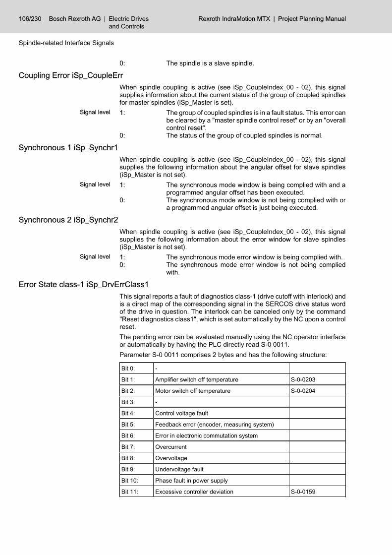
0: The spindle is a slave spindle.
Coupling Error iSp_CoupleErrWhen spindle coupling is active (see iSp_CoupleIndex_00 - 02), this signalsupplies information about the current status of the group of coupled spindlesfor master spindles (iSp_Master is set).1: The group of coupled spindles is in a fault status. This error can
be cleared by a "master spindle control reset" or by an "overallcontrol reset".
0: The status of the group of coupled spindles is normal.
Synchronous 1 iSp_Synchr1When spindle coupling is active (see iSp_CoupleIndex_00 - 02), this signalsupplies the following information about the angular offset for slave spindles(iSp_Master is not set).1: The synchronous mode window is being complied with and a
programmed angular offset has been executed.0: The synchronous mode window is not being complied with or
a programmed angular offset is just being executed.
Synchronous 2 iSp_Synchr2When spindle coupling is active (see iSp_CoupleIndex_00 - 02), this signalsupplies the following information about the error window for slave spindles(iSp_Master is not set).1: The synchronous mode error window is being complied with.0: The synchronous mode error window is not being complied
with.
Error State class-1 iSp_DrvErrClass1This signal reports a fault of diagnostics class-1 (drive cutoff with interlock) andis a direct map of the corresponding signal in the SERCOS drive status wordof the drive in question. The interlock can be canceled only by the command"Reset diagnostics class1", which is set automatically by the NC upon a controlreset.The pending error can be evaluated manually using the NC operator interfaceor automatically by having the PLC directly read S-0 0011.Parameter S-0 0011 comprises 2 bytes and has the following structure:
Bit 0: -
Bit 1: Amplifier switch off temperature S-0-0203
Bit 2: Motor switch off temperature S-0-0204
Bit 3: -
Bit 4: Control voltage fault
Bit 5: Feedback error (encoder, measuring system)
Bit 6: Error in electronic commutation system
Bit 7: Overcurrent
Bit 8: Overvoltage
Bit 9: Undervoltage fault
Bit 10: Phase fault in power supply
Bit 11: Excessive controller deviation S-0-0159
106/230 Bosch Rexroth AG | Electric Drivesand Controls
Rexroth IndraMotion MTX | Project Planning Manual
Spindle-related Interface Signals
Signal level
Signal level
Signal level

Bit 12: Communication Error
Bit 13: Position limit value exceeded S-0-0049
Bit 14: -
Bit 15: Manufacturer specific error S-0-0129
Fig.8-10: Structure of parameter S-0-0011
For analog spindles (/SP/SpFunc/Sp[1]/Base/SpType "Spindletype selection" (1040 00001)), this signal is not generated.
1: A diagnostics class -1 error has occurred.0: There is no diagnostics class -1 error.
Refer to the SERCOS interface Specifications for more informationon diagnostics class 1 errors.
Change of State Class-2 iSp_DrvChangeClass2This signal reports a change of diagnostics class 2 (switch off prewarning) andis a direct map of the corresponding signal in the SERCOS drive-status wordof the drive in question.The bit is set when diagnostic class -2 is modified and is reset after reading thestatus via parameter S-0-0012. Reading can occur manually using the NC op‐erator interface or automatically by having the PLC directly read S-0-0012.Parameter S-0-0012 comprises 2 bytes and contains the following warnings.
Bit 0: -
Bit 1: Amplifier overtemperature warning S-0-0311
Bit 2: Motor overtemperature warning S-0-0312
Bit 3to 14:
-
Bit 15: Manufacturer specific warning S-0-0181
Fig.8-11: Warnings parameter S-0-0012The effect of switch off warnings concerning the alteration bit can be sup‐pressed on the screen for diagnostics class 2 (S-0-0097).
For analog spindles (/SP/SpFunc/Sp[1]/Base/SpType "Spindletype selection" (1040 00001)), this signal is not generated.
Change of State Class-3 iSp_DrvChangeClass3This signal reports a change of diagnostics class -3 (operating status messag‐es) and is a direct map of the corresponding signal in the SERCOS drive-statusword of the drive in question. The bit is set when diagnostic class -3 is modifiedand is reset after reading the status via parameter S-0-0013. Reading can occurmanually using the NC operator interface or automatically by having the PLCdirectly read S-0-0013.Parameter S-0-0013 comprises 2 bytes and contains the following messages:
Bit 0: nact= ncomm S-0-0330
Bit 1: nact = 0 S-0-0331
Project Planning Manual | Rexroth IndraMotion MTX Electric Drivesand Controls
| Bosch Rexroth AG 107/230
Spindle-related Interface Signals
Signal level

Bit 2: ¦nact¦<¦nx¦ S-0-0332
Bit 3: ¦Md¦≥¦Mdx¦ S-0-0333
Bit 4: ¦Md¦≥¦Mdlimit¦ S-0-0334
Bit 5: ¦ncom¦>¦nlimit¦ S-0-0335
Bit 6: In-position S-0-0336
Bit 7: ¦P¦≥¦Px¦ S-0-0337
Bit 8: -
Bit 9: nact ≥min. spindle speed S-0-0339
Bit 10: ¦nact¦≥max. spindle speed S-0-0340
Bit 11: In-position rough S-0-0341
Bit 12: Target position reached S-0-0342
Bit 13: Interpolator halted S-0-0343
Bit 14: -
Bit 15: Manufacturer specific operating states S-0-0182
Fig.8-12: Messages of parameter S-0-0013The effect of operating states concerning the alteration bit can be suppressedon the screen for diagnostics class 3 (S-0-0098).
For analog spindles (/SP/SpFunc/Sp[1]/Base/SpType "Spindletype selection" (1040 00001)), this signal is not generated.
Test Mode iSp_DryRunThis signal indicates whether a spindle has been switched to test mode. In testmode, a spindle is still interpolated internally; however, the calculated commandvalues are only shown on the display and not transmitted to the drive.Test mode can be activated using a softkey, automatically for drives that arenot connected (no SERCOS ring present) or using machine parameter 100100010 /MAIN/Dr[1]/EnablVirtMode "Virtual drive".
Enabled for Power Activation iSp_DrvPowerThis signal is closely related to the signals Start inhibitor, Drive on, Driveready and Drive under control.The functional relationship is set out in detail in the signal diagram for the Driveinhibit signal (chapter "Drive on qSp_DrvOn" on page 97).1: Initialization of the SERCOS interface, the spindle drive and
the NC control are complete and no errors are present. Thissignal is a prerequisite for connecting the drive to power.
0: Power cannot be connected to the drive.
For analog spindles (/SP/SpFunc/Sp[1]/Base/SpType "Spindletype selection" (1040 00001)), this signal is not generated.
Drive Ready iSp_DrvReadyThis signal is closely related to the signals Start inhibitor, Drive on, Enabled forpower activation and Drive under control.
108/230 Bosch Rexroth AG | Electric Drivesand Controls
Rexroth IndraMotion MTX | Project Planning Manual
Spindle-related Interface Signals
Signal level

The functional relationship is set out in detail in the signal diagram for the Driveinhibit signal (chapter "Drive on qSp_DrvOn" on page 97).1: Power is connected to the affected drive. The signal remains
set until the drive is cut out.0: The power is not connected to the drive.
For analog spindles (/SP/SpFunc/Sp[1]/Base/SpType "Spindletype selection" (1040 00001)), this signal is not generated.
Drive in Operation iSp_DrvActThis signal is closely related to the signals Start inhibitor, Drive on, Enabled forpower activation and Drive ready.The functional relationship is set out in detail in the signal diagram for the Driveinhibit signal (chapter "Drive on qSp_DrvOn" on page 97).
For analog spindles (/SP/SpFunc/Sp[1]/Base/SpType "Spindletype selection" (1040 00001)), this signal is not generated.
1: The control loop remains closed and torque is applied on thedrive. The spindle can be rotated unless it is locked by anyother function, e.g. Spindle inhibit.
0: The control loop is open and no torque is applied on the drive.
When changing from logic 1 to logic 0, spindle stop (M5) is triggeredwithin the NC.
Project Planning Manual | Rexroth IndraMotion MTX Electric Drivesand Controls
| Bosch Rexroth AG 109/230
Spindle-related Interface Signals
Signal level
Signal level

Bosch Rexroth AG | Electric Drivesand Controls
Rexroth IndraMotion MTX | Project Planning Manual

9 Auxiliary Functions9.1 General
Auxiliary functions are programmed in the NC part program.All bit-coded auxiliary functions programmed in an NC block are mapped inparallel to markers.Output of non-bit-coded auxiliary functions can be preset using machine pa‐rameter /AUXF/OutBehav/OutBehavMode "Output mode of the auxiliary func‐tions" 301000015:0: Only bit-coded auxiliary functions are output in parallel.1: All auxiliary functions of an NC block are output in parallel.Parallel data transfer helps avoid machine downtimes.The following conventions apply to auxiliary functions:● Every channel has several auxiliary functions. The names (auxiliary func‐
tion types) of auxiliary functions (M, S, T, ...) are specified in machineparameter /AUXF/ClassDef/Class[1]/AuxFuncName "Names of auxiliaryfunctions" (3010 00030).
● An auxiliary function can be mapped as a– bit-coded auxiliary function– 32-bit BCD-coded auxiliary function– 64-bit BCD-coded auxiliary function– INTEGER-coded auxiliary function (32 bits)– FLOAT-coded auxiliary function (32 bits)– DOUBLE-coded auxiliary function (64 bits)on an operand range (machine parameter /AUXF/ClassDef/Class[1]/Ena‐blAuxFunc, /AUXF/ClassDef/Class[1]/AuxFuncChDep, /AUXF/ClassDef/Class[1]/Bit, /AUXF/ClassDef/Class[1]/Bcd32, /AUXF/ClassDef/Class[1]/Int, /AUXF/ClassDef/Class[1]/Float, /AUXF/ClassDef/Class[1]/Double"Classes of auxiliary functions" (3010 00040)). These auxiliary functionscan be defined both channel-dependently and channel-independently.
● For each channel, several auxiliary function types can be declared as bit-coded auxiliary functions (machine parameter /AUXF/ClassDef/Class[1]/AuxFuncName "Names of auxiliary functions" (3010 00030)), e.g. theauxiliary function with the designation M and the auxiliary function with thedesignation H.
● The start addresses of bit-coded auxiliary functions are set individually foreach channel in machine parameter /AUXF/PlcIf/ChDep/ChIf[1]/AddrCh‐DepBit "Addresses of the channel-specific bit-coded auxiliary func‐tions" (2060 00009).
● The output of the auxiliary functions is asynchronously with regard to theprocession of the IEC tasks. This means that also within PLC procession,an auxiliary function can be transfered by the CNC to PLC in the markerarea.If an auxiliary function is output within a PLC cycle and has already beenacknowledged, the help function output cannot be recorded using tracefunction, since this record is only carried out at the end of the PLC task.
● For this reason, auxiliary functions of type Double must always be definedso that they require acknowledgement to ensure the consistency of theauxiliary function value.
Project Planning Manual | Rexroth IndraMotion MTX Electric Drivesand Controls
| Bosch Rexroth AG 111/230
Auxiliary Functions

Furthermore, the values of the auxiliary function can only be accessedbefore the acknowledgement was carried out. The value can change in‐consistently after the acknowledgement!
● Only the change signal (bit 0) may be reset to acknowledge non-bit-codedauxiliary functions.
● If several auxiliary functions that are not bit-coded and of the same typeare defined, they are all stored one after the other within the marker area.The parameter index ( Macoda-Id 3010 00080 ) defines where the auxiliaryfunctions of a type are located. The index always starts with 0.
● Assignment of auxiliary function types and addresses in the marker area:
NC PLC IEC typeMacoda ID for marker address
Kanalabh(channel ind.)
Kanalunabh(channel ind.)
32 bit BCD DWORD MT_AuxFuncBCD32_t 2060 00010 2060 00003[6]
64 bit BCD DWORD1,DWORD2 MT_AuxFuncBCD64_t 2060 00011 2060 00003[7]
INTEGER DINT MT_AuxFuncInt_t 2060 00012 2060 00020[1]
FLOAT REAL MT_AuxFuncReal_t 2060 00013 2060 00020[2]
DOUBLE LREAL MT_AuxFuncLReal_t 2060 00014 2060 00020[3]
9.2 Bit-coded Auxiliary Functions Auxiliary functions are most often required in the PLC sequential program inthe form of individual signals. In this way, for example, the coolant is switchedon/off, a clamp is opened/closed or a cylinder is extended/retracted.Auxiliary functions are programmed in the NC part program in order to triggerthese functions. The decoded auxiliary functions are mapped on an operandrange (e.g. markers). The absolute size of this range is dependent on the num‐ber of auxiliary functions which are to be decoded as well as on the number ofchannels (machine parameter /MAIN/NofCh "Number of channels" (904000001)).The start address of the operand range is defined for each channel in machineparameter /AUXF/PlcIf/ChDep/ChIf[1]/AddrChDepBit "Addresses of the chan‐nel-specific bit-coded auxiliary functions" (2060 00009).Example:
Bit-coded auxiliary functions
3 channels are defined in the NC. For each channel, 128 (machineparameter /AUXF/NofAuxFunc/ChDep/ChDepBit "Number of auxiliary func‐tions [2]" (3010 00010)) decoded auxiliary functions of type M are declared(machine parameter /AUXF/ClassDef/Class[1]/AuxFuncName "Names of aux‐iliary functions" (3010 00030)); the operand range is to be at maker M200.0 forchannel 0 (machine parameter /AUXF/PlcIf/ChDep/ChIf[1]/AddrChDepBit "Ad‐dresses of the channel-specific bit-coded auxiliary functions [1]" (2060 00009)).The auxiliary functions of the remaining channels follow one another (machineparameter /AUXF/PlcIf/ChDep/ChIf[2]/AddrChDepBit "Addresses of the chan‐nel-specific bit-coded auxiliary functions [2]" (2060 00009) -> M240, Machineparameter /AUXF/PlcIf/ChDep/ChIf[3]/AddrChDepBit "Addresses of the chan‐nel-specific bit-coded auxiliary functions [3]" (2060 00009) -> M280).Owing to these parameters, the marker field has the following structure:
112/230 Bosch Rexroth AG | Electric Drivesand Controls
Rexroth IndraMotion MTX | Project Planning Manual
Auxiliary Functions
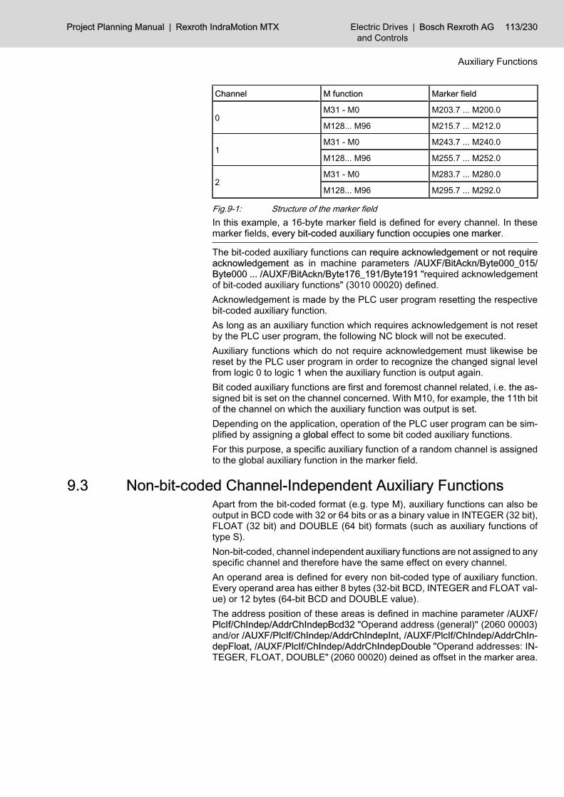
Channel M function Marker field
0M31 - M0 M203.7 ... M200.0
M128... M96 M215.7 ... M212.0
1M31 - M0 M243.7 ... M240.0
M128... M96 M255.7 ... M252.0
2M31 - M0 M283.7 ... M280.0
M128... M96 M295.7 ... M292.0
Fig.9-1: Structure of the marker fieldIn this example, a 16-byte marker field is defined for every channel. In thesemarker fields, every bit-coded auxiliary function occupies one marker.
The bit-coded auxiliary functions can require acknowledgement or not requireacknowledgement as in machine parameters /AUXF/BitAckn/Byte000_015/Byte000 ... /AUXF/BitAckn/Byte176_191/Byte191 "required acknowledgementof bit-coded auxiliary functions" (3010 00020) defined.Acknowledgement is made by the PLC user program resetting the respectivebit-coded auxiliary function.As long as an auxiliary function which requires acknowledgement is not resetby the PLC user program, the following NC block will not be executed.Auxiliary functions which do not require acknowledgement must likewise bereset by the PLC user program in order to recognize the changed signal levelfrom logic 0 to logic 1 when the auxiliary function is output again.Bit coded auxiliary functions are first and foremost channel related, i.e. the as‐signed bit is set on the channel concerned. With M10, for example, the 11th bitof the channel on which the auxiliary function was output is set.Depending on the application, operation of the PLC user program can be sim‐plified by assigning a global effect to some bit coded auxiliary functions.For this purpose, a specific auxiliary function of a random channel is assignedto the global auxiliary function in the marker field.
9.3 Non-bit-coded Channel-Independent Auxiliary Functions Apart from the bit-coded format (e.g. type M), auxiliary functions can also beoutput in BCD code with 32 or 64 bits or as a binary value in INTEGER (32 bit),FLOAT (32 bit) and DOUBLE (64 bit) formats (such as auxiliary functions oftype S).Non-bit-coded, channel independent auxiliary functions are not assigned to anyspecific channel and therefore have the same effect on every channel.An operand area is defined for every non bit-coded type of auxiliary function.Every operand area has either 8 bytes (32-bit BCD, INTEGER and FLOAT val‐ue) or 12 bytes (64-bit BCD and DOUBLE value).The address position of these areas is defined in machine parameter /AUXF/PlcIf/ChIndep/AddrChIndepBcd32 "Operand address (general)" (2060 00003)and/or /AUXF/PlcIf/ChIndep/AddrChIndepInt, /AUXF/PlcIf/ChIndep/AddrChIn‐depFloat, /AUXF/PlcIf/ChIndep/AddrChIndepDouble "Operand addresses: IN‐TEGER, FLOAT, DOUBLE" (2060 00020) deined as offset in the marker area.
Project Planning Manual | Rexroth IndraMotion MTX Electric Drivesand Controls
| Bosch Rexroth AG 113/230
Auxiliary Functions
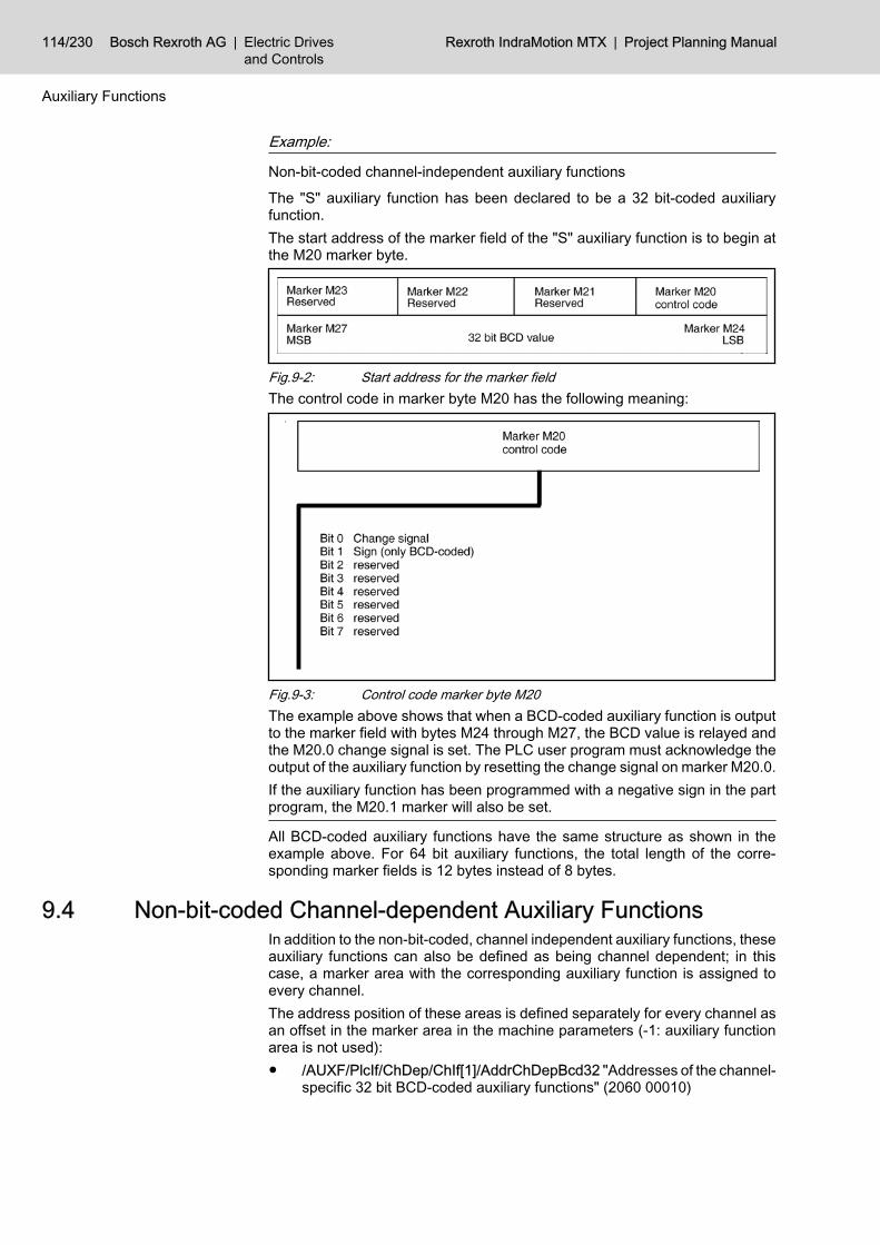
Example:
Non-bit-coded channel-independent auxiliary functions
The "S" auxiliary function has been declared to be a 32 bit-coded auxiliaryfunction.The start address of the marker field of the "S" auxiliary function is to begin atthe M20 marker byte.
Fig.9-2: Start address for the marker fieldThe control code in marker byte M20 has the following meaning:
Fig.9-3: Control code marker byte M20The example above shows that when a BCD-coded auxiliary function is outputto the marker field with bytes M24 through M27, the BCD value is relayed andthe M20.0 change signal is set. The PLC user program must acknowledge theoutput of the auxiliary function by resetting the change signal on marker M20.0.If the auxiliary function has been programmed with a negative sign in the partprogram, the M20.1 marker will also be set.
All BCD-coded auxiliary functions have the same structure as shown in theexample above. For 64 bit auxiliary functions, the total length of the corre‐sponding marker fields is 12 bytes instead of 8 bytes.
9.4 Non-bit-coded Channel-dependent Auxiliary FunctionsIn addition to the non-bit-coded, channel independent auxiliary functions, theseauxiliary functions can also be defined as being channel dependent; in thiscase, a marker area with the corresponding auxiliary function is assigned toevery channel.The address position of these areas is defined separately for every channel asan offset in the marker area in the machine parameters (-1: auxiliary functionarea is not used):● /AUXF/PlcIf/ChDep/ChIf[1]/AddrChDepBcd32 "Addresses of the channel-
specific 32 bit BCD-coded auxiliary functions" (2060 00010)
114/230 Bosch Rexroth AG | Electric Drivesand Controls
Rexroth IndraMotion MTX | Project Planning Manual
Auxiliary Functions

● "Adresses of the channel-specific 64 bit BCD-coded auxiliary func‐tions" (2060 00011)
● /AUXF/PlcIf/ChDep/ChIf[1]/AddrChDepInt "Addresses of the channel-specific INTEGER-codes auxiliary functions" (2060 00012)
● /AUXF/PlcIf/ChDep/ChIf[1]/AddrChDepFloat "Addresses of the channel-specific FLOAT-codes auxiliary functions" (2060 00013)
● /AUXF/PlcIf/ChDep/ChIf[1]/AddrChDepDouble "Addresses of the chan‐nel-specific DOUBLE-codes auxiliary functions" (2060 00014)
Example:
Non-bit-coded channel-dependent auxiliary functions
The "T" auxiliary function has been declared to be a channel dependent INTE‐GER coded auxiliary function.The start address of the marker field of the "T" auxiliary function is to begin:● at marker field M112 in channel 0● at marker field M120 in channel 1● at marker field M128 in channel 2
Fig.9-4: Channel-dependent INTEGER auxiliary function of channel 0
Fig.9-5: Channel-dependent INTEGER auxiliary function of channel 1
Fig.9-6: Channel-dependent INTEGER auxiliary function of channel 2The control code in marker byte M20 has the following meaning:
Project Planning Manual | Rexroth IndraMotion MTX Electric Drivesand Controls
| Bosch Rexroth AG 115/230
Auxiliary Functions

Fig.9-7: Control code marker byte M20
The example above shows that when an INTEGER coded auxiliary function"T" is output in channel 1 to the marker field with bytes M124 through M127,the binary value is relayed and the M120.0 change signal is also set. The PLCuser program must acknowledge the output of the auxiliary function by resettingthe change signal on marker M120.0.All non-bit-coded auxiliary functions have the same structure as shown in theexample above. For 64-bit auxiliary functions, the total length of the corre‐sponding marker fields is 12 bytes instead of 8 bytes.
116/230 Bosch Rexroth AG | Electric Drivesand Controls
Rexroth IndraMotion MTX | Project Planning Manual
Auxiliary Functions

10 Access to Digital I/Os Access to digital I/Os from the PLC user program is adapted in the machineparameters of group 4075. This adaptation involves setting the I/O signal as‐signments in the PLC and the application of PLC addresses.An extension card with digital I/Os is available for the IndraMotion MTX. Fur‐thermore, decentral I/Os are possible using PROFIBUS-DP.The IndraMotion MTX has a PROFIBUS-DP interface which can be used as aDP master interface .This interface is designed for the connection of decentralized PROFIBUS-DPperipherals.The I/O configuration of the PROFIBUS-DP is effected via the IndraLogic userinterface. The DPConfi diagnostic tool can be used to analyze errors.
An error reported by the DP master in the DP master status doesnot force a STOP of the PLC. If error handling is required, this mustbe programmed in the PLC user program.
Project Planning Manual | Rexroth IndraMotion MTX Electric Drivesand Controls
| Bosch Rexroth AG 117/230
Access to Digital I/Os
PROFIBUS-DP interface

Bosch Rexroth AG | Electric Drivesand Controls
Rexroth IndraMotion MTX | Project Planning Manual
11 Program Modules11.1 General Structure of Program Modules
The integrated program modules can be called up cyclically and with parame‐ters set by the PLC sequential program.If a module is called several times before the data from the previous call arereceived, ensure that another instance of the module is used.An error code is output if an error occurs in the execution of a function whichprevents the proper execution of the respective function. Errors may be causedby, among other things, incorrect parameterization, e.g. an invalid channelnumber. Also, system errors may occur, which will also be displayed with therespective error code.The error code has a length of 2 bytes:in the error code, the error type or error state are represented as a sign number.There are two categories of errors and states:1. General errors and states
These are errors and states caused by calling a function with incorrectparameter settings or an internal NC error.
2. Function-specific errors and statesThese are errors and states that are reported as an acknowledgementupon the execution of a function.
Because some of the error messages are function-specific, they areexplained in the description of the respective function.Error codes are defined by Rexroth and are updated as required inthe context of new releases.
The function starts when "Start" is set and "Active" is not set. If "Start" is notreset using the PLC sequential program, it is reset when the function has beencarried out. "Active" is set until the function has been carried out. As soon asthe data have been returned, the function is completed and "Active" is reset.The function can be completed within a call.The programming example for the first program module is shown in the PLCprogramming languages KOP, FUP, AWL and ST. All other programming ex‐amples are shown only in KOP.
11.2 Reading Actual Axis Values (MT_ScsPos)11.2.1 Function
This program module supplies the actual values of all axes at the time of therequest.The actual axis value feedback is scaled to 0.1 μm and represented as an in‐teger with 4 bytes.As regards cyclic calls of this module, please note that the number of callsshould be limited to what is necessary to reduce strain on the system capacity.This can be achieved by, for example, timer programming, time-controlledmodules or by calling the module only every nth cycle.The module may be called once or repeatedly in a PLC-cycle; calls may beunconditional or conditional.
Project Planning Manual | Rexroth IndraMotion MTX Electric Drivesand Controls
| Bosch Rexroth AG 119/230
Program Modules

Fig.11-1: Module MT_ScsPosThe module is called with the following parameters:Start: Flag for a new requestChan: desired channel numberDestAddr: address for the data (ADR(<Variable>))Size: Max. size of the memory for the data (in bytes).
(SIZEOF(<Variable>)The feedback parameters are:Active: Flag that displays if the function is still active.Error: Error detection: FALSE means that the function has been pro‐
cessed without errors.ErrorNo: Error code: valid only if Error = TRUE.NofElem: Number of returned elements
This module provides actual data feedback of every axis, regard‐less of the channel number transferred.
The function starts when Start is set and Active is not set. If Start is not resetusing the PLC sequential program, it is reset when the function has been carriedout.Active is set until the function has been carried out. As soon as the data havebeen returned, the function is completed and Active is reset.
11.2.2 Configuration Example3 axes are defined in channel 1. The actual axis values are to be queried withthe positive edge of PLC input %IX40.2.The task is triggered with the increasing edge at input %IX40.2.Given these requirements, the MT_ScsPos program module call may be struc‐tured as follows:
120/230 Bosch Rexroth AG | Electric Drivesand Controls
Rexroth IndraMotion MTX | Project Planning Manual
Program Modules
Module parameters
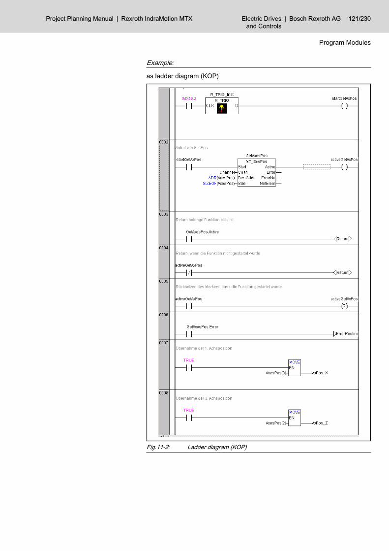
Example:
as ladder diagram (KOP)
Fig.11-2: Ladder diagram (KOP)
Project Planning Manual | Rexroth IndraMotion MTX Electric Drivesand Controls
| Bosch Rexroth AG 121/230
Program Modules

Example:
as function plan (FUP)
Fig.11-3: Function plan (FUP)
Example:
as instruction list (AWL)(* Increasing edge --> startGetAxPos *)LD %IX40.2STR_TRIG_Inst.CLKCALR_TRIG_Inst
122/230 Bosch Rexroth AG | Electric Drivesand Controls
Rexroth IndraMotion MTX | Project Planning Manual
Program Modules

(* Call of the function module for reading the axis posi-tion *)LDR_TRIG_Inst.QST startGetAxPosLD startGetAxPosST GetAxesPos.StartLD AxesPosADRST GetAxesPos.DestAddrLD AxesPosSIZEOFST GetAxesPos.SizeCAL GetAxesPos(Chan=Channel)(* Set marker indicating that the function has been star-ted *)LD GetAxesPos.ActiveST activeGetAxPos(* Return as long as the function is active *)RETC(* Return if the function has not been started *)LD activeGetAxPosRETCNR activeGetAxPos(* Reset marker *)(* Error handling in case of error*)LD GetAxesPos.ErrorJMPC error(* Positions read with no errors *)(* Transfer of 1st axis position *)LD AxesPos[0]ST AxPos_X(* Transfer of 3rd position *)LD AxesPos[3]ST AxPos_ZRETError:(* Error handling *)RET
Example:
as structured text (ST)(* Increasing edge --> startGetAxPos *)R_TRIG_Inst(CLK := %IX40.2);StartGetAxPos:=R_TRIG_Inst.Q;(* Call GetAxesPos *)
Project Planning Manual | Rexroth IndraMotion MTX Electric Drivesand Controls
| Bosch Rexroth AG 123/230
Program Modules

GetAxesPos(Start:=startGetAxPos,Chan:=Channel,DestAddr:=ADR(AxesPos), Size:=SIZEOF(AxesPos));(* Set marker indicating that the function has been star-ted *)activeGetAxPos:=GetAxesPos.Active;(* Return as long as the function is still active *)IF ( GetAxesPos.Active )THENRETURN ;END_IF(* Return if the function has not been started *)IF ( activeGetAxPos =NOT xxx ) THENRETURN ;END_IF(* Reset marker *)ActiveGetAxPos := FALSE;IF ( GetAxesPos.Error) THEN(* Error handling *)RETURN ;ELSE(* Axis positions read with no errors *)(* Transfer of 1st axis position *)AxPos_X := AxesPos[0];(* Transfer of 3rd position *)AxPos_Z := AxesPos[2];END_IF
11.2.3 Status MessagesIf an error or status occurs which prevents proper execution of the function aftercalling this function, error bit Error is set.Furthermore, the type of error or status is represented in the ErrorNo in the formof a number:General errors and stateswhen calling the function with incorrect parameters or with an internal NC error:1: Invalid channel number-6: No equipment for transmitting the task is currently available.-3: Data overflow: Only those data that fit into the available mem‐
ory are returned.-1: General parameter errors.
11.3 Program Selection/Deselection (MT_ProgSel)11.3.1 Function
This module facilitates the selection and deselection of an NC-part program viathe PLC sequential program.
124/230 Bosch Rexroth AG | Electric Drivesand Controls
Rexroth IndraMotion MTX | Project Planning Manual
Program Modules
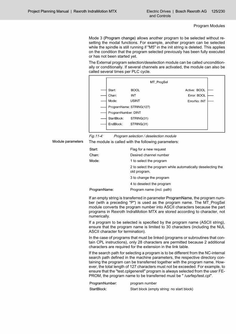
Mode 3 (Program change) allows another program to be selected without re‐setting the modal functions. For example, another program can be selectedwhile the spindle is still running if "M5" in the init string is deleted. This applieson the condition that the program selected previously has been fully executedor has not been started yet.The External program selection/deselection module can be called uncondition‐ally or conditionally. If several channels are activated, the module can also becalled several times per PLC cycle.
Fig.11-4: Program selection / deselection moduleThe module is called with the following parameters:
Start: Flag for a new requestChan: Desired channel numberMode: 1 to select the program
2 to select the program while automatically deselecting theold program,3 to change the program4 to deselect the program
ProgramName: Program name (incl. path)
If an empty string is transferred in parameter ProgramName, the program num‐ber (with a preceding "P") is used as the program name. The MT_ProgSelmodule converts the program number into ASCII characters because the partprograms in Rexroth IndraMotion MTX are stored according to character, notnumerically.If a program to be selected is specified by the program name (ASCII string),ensure that the program name is limited to 30 characters (including the NULASCII character for termination).In the case of programs that must be linked (programs or subroutines that con‐tain CPL instructions), only 28 characters are permitted because 2 additionalcharacters are required for the extension in the link table.If the search path for selecting a program is to be different from the NC-internalsearch path defined in the machine parameters, the respective directory con‐taining the program can be transferred together with the program name. How‐ever, the total length of 127 characters must not be exceeded. For example, toensure that the "test.cplgenerell" program is always selected from the user FE‐PROM, the program name to be transferred must be " /usrfep/test.cpl".
ProgramNumber: program numberStartBlock: Start block (empty string: no start block)
Project Planning Manual | Rexroth IndraMotion MTX Electric Drivesand Controls
| Bosch Rexroth AG 125/230
Program Modules
Module parameters

EndBlock: End block (empty string: no end block)
The feedback parameters are:
Active: Flag that displays if the function is still active.Error: Error detection: FALSE means that the function has been
processed without errors.ErrorNo: Error code: valid only if Error = TRUE
An NC part program can be selected only if Automatic mode is active.The function starts when Start is set and Active is not set. If Start is not resetusing the PLC sequential program, it is reset when the function has been carriedout.Active is set until the function has been carried out. As soon as the programhas been selected/deselected, the function is completed and Active is reset.Parameter Mode specifies whether a program is selected or a program that wasalready active is to be deselected.To deselect a program, only the channel number need to be entered. Thechannel number is always entered as an integer.If an empty string is transferred in parameter ProgramName, the program num‐ber (with a preceding "P") is used as the program name. The MT_ProgSelmodule converts the program number into ASCII characters because the partprograms in the IndraMotion MTX are stored according to character, not nu‐merically.If a program to be selected is specified by the program name (ASCII string),ensure that the program name is limited to 29 characters, with a trailing NULASCII character for termination. If the search path for selecting a program is tobe different from the NC-internal search path defined in the machine parame‐ters, the respective directory containing the program can be transferred togeth‐er with the program name. However, the total length of 30 characters must notbe exceeded. For example, to ensure that the "test.cplgenerell" program is al‐ways selected from the user FEPROM, "/usrfep/test.cpl" must be transferredas program name.If the part program is to be started at a certain block, a start block can be definedin addition to the program name. The start block can be an NC block accordingto DIN 66025 (always begins with "N") or a CPL block (no "N" in front of theblock number). Therefore, the start block is defined as a character string. Thestart block length is limited to 9 ASCII characters, with a trailing NUL ASCIIcharacter for termination.If the part program does not complete machining (M30) but is to terminate be‐fore the end, an end block can be defined. The same rules as for defining startblocks apply to defining end blocks.If a program is still active when another program is to be selected, it suffices toselect the program with Mode 2 or 3. Accordingly, the program is deselectedautomatically provided the NC is in Ready or Stopped status.
11.3.2 Configuration ExampleThe NC part program with the program name "Labor.npg" is to be activated inchannel 1.The task is triggered with the increasing edge at input %IX40.3.Module MT_ProgSel could be called as follows:
126/230 Bosch Rexroth AG | Electric Drivesand Controls
Rexroth IndraMotion MTX | Project Planning Manual
Program Modules

Fig.11-5: Calling module MT_ProgSel
11.3.3 Status MessagesIf an error or status occurs which prevents proper execution of the function aftercalling this function, error bit Error is set.Furthermore, the type of error or status is represented in the ErrorNo in the formof a number:General errors and stateswhen calling the function with incorrect parameters or with an internal NC error:-6: No equipment for transmitting the task is currently available.
Project Planning Manual | Rexroth IndraMotion MTX Electric Drivesand Controls
| Bosch Rexroth AG 127/230
Program Modules

-1: General parameter errors.Function-specific errors and statesas acknowledgement after executing the function:1: Illegal number of channels.Errors or states occurring upon program selection:2: Channel is busy.3 : Control reset is currently being executed on the channel.4: The program name is too long.5: Axes have not been referenced.6: Program cannot be opened.7: Error during program selection.8: Either the wrong operation mode or none at all has been se‐
lected.25: Syntax error in the selected program.Errors or states occurring upon program deselection:1 : Illegal number of channels.3 : Control reset is currently being executed on the channel.10 : No program is selected.11 : Program is running and feed hold is not present.
11.4 NC Block Input (MT_NcBlk)11.4.1 Function
This program module facilitates the input of an NC block via the PLC sequentialprogram. The NC channel must be in MDI or Automatic mode in this case. NCblock input can be made even while the program is running provided no axisaddresses are input that would have an impact on the running machining proc‐ess. In this way, for example, command values for auxiliary axes or auxiliaryfunctions can be transferred to the NC.If an NC block is input that would have an impact on the running machiningprocess, such as inputting a feed or programming a synchronous axis, a syntaxerror occurs.The input block must be completely processed before another block can beinput in the same channel.This module can be called unconditionally or conditionally.
Fig.11-6: Module MT_NcBlkThe module is called with the following parameters:
128/230 Bosch Rexroth AG | Electric Drivesand Controls
Rexroth IndraMotion MTX | Project Planning Manual
Program Modules
Module parameters

Start: Flag for a new request.Chan: Desired channel number.NcBlock: NC block to be executed.
The feedback parameters are:
Active: Flag that displays if the function is still active.Error: Error detection: FALSE means that the function has been
processed without errors.ErrorNo: Error code: valid only if Error = TRUE
The function starts when Start is set and Active is not set. If Start is not resetusing the PLC sequential program, it is reset when the function has been carriedout.Active is set until the function has been carried out, i.e. the input block hasbecome active. However, the movement must not yet be complete.If an asynchronous movement is input whose end point has not been reachedyet, this ensures that the axis travel command is already set at the time thefunction is completed.When the function is terminated, the status Active is reset.The NC executes the NC block immediately after receipt, without an additionalNC start signal.
11.4.2 Configuration ExampleNC block "G91 X10 Y5 Z1 F10000" is to be transferred in channel 1.Module MT_NcBlk could be called as follows:
Project Planning Manual | Rexroth IndraMotion MTX Electric Drivesand Controls
| Bosch Rexroth AG 129/230
Program Modules

Fig.11-7: Calling module MT_NcBlk
130/230 Bosch Rexroth AG | Electric Drivesand Controls
Rexroth IndraMotion MTX | Project Planning Manual
Program Modules

Fig.11-8: Calling module MT_NcBlk
11.4.3 Status MessagesIf an error or status occurs which prevents proper execution of the function aftercalling this function, error bit Error is set.Furthermore, the type of error or status is represented in the ErrorNo in the formof a number:General errors and stateswhen calling the function with incorrect parameters or with an internal NC error:-6: No equipment for transmitting the task is currently available.-1: General parameter errors.Function-specific errors and statesas acknowledgement after executing the function:1: Invalid channel number2: Channel is busy.3: The channel is just being (control) reset.4: NC block is too long.5: Axes have not been referenced.7: NC block selection was cancelled via control reset.8: Either the wrong operation mode or none at all has been se‐
lected.25: A runtime error was detected in the NC input, e.g. a syntax
error.
Project Planning Manual | Rexroth IndraMotion MTX Electric Drivesand Controls
| Bosch Rexroth AG 131/230
Program Modules

11.5 Extended NC Block Input (MT_NcBlkExt)11.5.1 Function
The program module Extended NC block selection facilitates the input of an NCblock via the PLC sequential program. Via input parameter Options, the pro‐cessing of default to NC side can be influenced. The NC channel must be inMDI or Automatic mode in this case. NC block input can be made even whilethe program is running provided no axis addresses are input that would havean impact on the running machining process. In this way, for example, com‐mand values for auxiliary axes or auxiliary functions can be transferred to theNC.If an NC block is input that would have an impact on the running machiningprocess, such as inputting a feed or programming a synchronous axis, a syntaxerror occurs.The input block must be completely processed before another block can beinput in the same channel.This module can be called unconditionally or conditionally.
Fig.11-9: Calling module MT_NcBlkExtThe module is called with the following parameters:
Start: Flag that executes a new request.Chan: Desired channel number.Options: Options is from type "MT_NcBlk_Options_t" and can apply
the following values to control the block selection:NO_AUTO_STARTNo automatic start after activating the NC block. ProcessingNC block must be started via signal qCh_NcStart per PLC.NO_CHAN_CHANGEIf the transferred channel is occupied, the task is not de‐toured automatically into the AutoStart channel.PROCESS_DELETEIf meanwhile the block selection is processed in the channel,a program is active (ready) or feed stop is active, this is de‐selected and the predefined NC block will be active.
NcBlock: NC block to be executed.
The feedback parameters are:
Active: Flag that displays if the function is still active.Error: Error detection: FALSE means that the function has been
processed without errors.ErrorNo: Error code: valid only if Error = TRUE
132/230 Bosch Rexroth AG | Electric Drivesand Controls
Rexroth IndraMotion MTX | Project Planning Manual
Program Modules
Module parameters
The function starts when the Start bit is set and Active is not set. If Bit Start isnot reset using the PLC sequential program, it is reset when the function hasbeen carried out.Active is set until the function has been carried out, i.e. the input block hasbecome active. However, the movement must not yet be complete.If an asynchronous movement is input whose end point has not been reachedyet, this ensures that the axis travel command is already set at the time thefunction is completed. On the end of the traversing movement, "iAx_InPos" canbe requested via interface signal.When the function is terminated, the status Active is reset.If option bit NO_AUTO_START is not set, the NC executed the NC block im‐mediately after receipt without additional NC start signal.
11.5.2 Configuration ExampleNC block "G91 X10 Y5 Z1 F10000" should be transferred in channel 1and nodetour should occur in the auto start channel.Module MT_NcBlkExt could be called as follows:
Project Planning Manual | Rexroth IndraMotion MTX Electric Drivesand Controls
| Bosch Rexroth AG 133/230
Program Modules
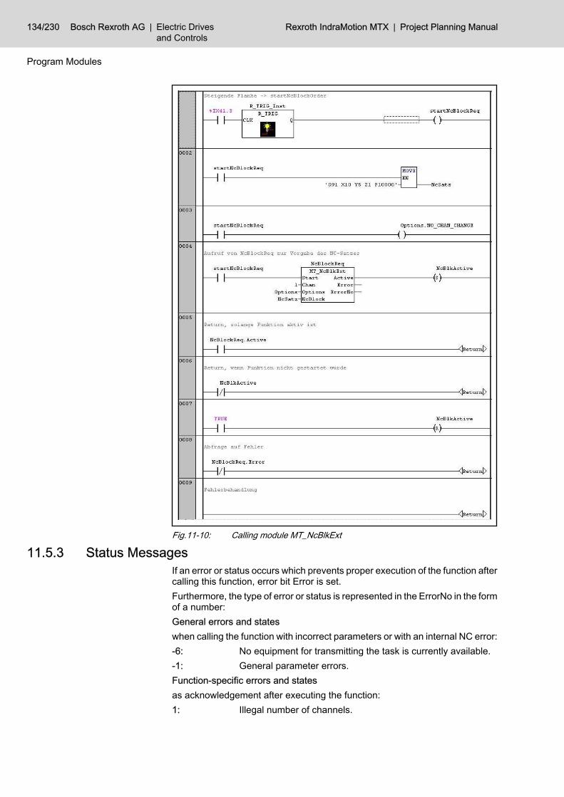
Fig.11-10: Calling module MT_NcBlkExt
11.5.3 Status MessagesIf an error or status occurs which prevents proper execution of the function aftercalling this function, error bit Error is set.Furthermore, the type of error or status is represented in the ErrorNo in the formof a number:General errors and stateswhen calling the function with incorrect parameters or with an internal NC error:-6: No equipment for transmitting the task is currently available.-1: General parameter errors.Function-specific errors and statesas acknowledgement after executing the function:1: Illegal number of channels.
134/230 Bosch Rexroth AG | Electric Drivesand Controls
Rexroth IndraMotion MTX | Project Planning Manual
Program Modules

2: Channel is busy.3: The channel is just being (control) reset.4: NC block is too long.5: Axes have not been referenced.7: NC block selection was cancelled via control reset.8: Either the wrong operation mode or none at all has been se‐
lected.25: A runtime error was detected in the NC input, e.g. a syntax
error.
11.6 Temperature Compensation (MT_TempComp)11.6.1 Function
This program module allows the user to set a compensation value via the PLCsequential program to offset temperature impacts. The PLC program transfersthe temperature compensation value for a certain number of axes, with tem‐perature compensation values becoming active immediately upon transfer. Theeffect of the compensation value does not depend on the position.To prevent servo errors, the differences of the compensation values must notexceed the jumping ability of the axes.This module can be called unconditionally or conditionally.
Fig.11-11: Calling of module MT_TempCompThe module is called with the following parameters:
Start: Flag for a new request.AxisNo: Physical axis index from which values can be adopted.NmbOfValues: Number of compensation values.DataAddr: Address of data (field for LREAL values).
The feedback parameters are:
Active: Flag that displays if the function is still activeError: Error detection: FALSE means that the function has been
processed without errors.ErrorNo: Error code: valid only if Error = TRUE.
The function starts when Start is set and Active is not set. If Start is not resetusing the PLC sequential program, it is reset when the function has been carriedout.Active is set until the function has been carried out. As soon as the NC hasacknowledged the function, the function is completed and Active is reset.The physical axis index must be entered in AxisNo, and the number of com‐pensation values must be entered in NmbOfValues. On the NC side, the
Project Planning Manual | Rexroth IndraMotion MTX Electric Drivesand Controls
| Bosch Rexroth AG 135/230
Program Modules
Module parameters

transferred temperature compensation values are calculated as of the axis withthe transferred "axis index". The axis index starts at 1 for the 1st axis.The temperature compensation is immediately accepted by the NC.
11.6.2 Configuration ExampleTo compensate the temperature impact, a compensation value of 123 μm is tobe input for the 4th axis and a compensation value of 234 μm is to be input forthe 5th axis.The task is triggered with the increasing edge at input %IX41.3.Module MT_TempComp could be called as follows:
Fig.11-12: Calling module MT_TempComp
136/230 Bosch Rexroth AG | Electric Drivesand Controls
Rexroth IndraMotion MTX | Project Planning Manual
Program Modules

Fig.11-13: Calling module MT_TempComp
11.6.3 Status MessagesIf an error or status occurs which prevents proper execution of the function aftercalling this function, error bit Error is set.Furthermore, the type of error or status is represented in the ErrorNo in the formof a number:General errors and stateswhen calling the function with incorrect parameters or with an internal NC error:-6: No equipment for transmitting the task is currently available.-1: General parameter errors.Function-specific errors and statesas acknowledgement after executing the function:16: Too many compensation values (displayed with the axis num‐
ber, if applicable).24: Invalid axis number33: The last compensation value has not yet been accepted by the
interpolator.
11.7 Reading Machine Parameter (MT_CfgData)11.7.1 Function
This program module supplies the values of a machine parameter block.The variables for the values must be defined sufficiently large for all individualparameters of the block to be stored there.This module does not convert value formats, so that real values are returnedas real numbers.The module may be called once or repeatedly in a PLC-cycle; calls may beunconditional or conditional.
Project Planning Manual | Rexroth IndraMotion MTX Electric Drivesand Controls
| Bosch Rexroth AG 137/230
Program Modules

Fig.11-14: Calling module MT_CfgDataThe module is called with the following parameters:
Start: Flag for a new request.Chan: Desired channel number for channel-specific machine pa‐
rameters.BlkNo: Number of machine parameter block.DestAddr: Address for the data.Size: Max. size of the memory for the data (in bytes).
The feedback parameters are:
Active: Flag that displays if the function is still active.Error: Error detection: FALSE means that the function has been
processed without errors.ErrorNo: Error code: valid only if Error = TRUE.NofElem: Number of returned elements.
The function starts when Start is set and Active is not set. If Start is not resetusing the PLC sequential program, it is reset when the function has been carriedout.Active is set until the function has been carried out. As soon as the data havebeen returned, the function is completed and Active is reset.While reading a channel-specific block, the values that refer to the channeltransferred in Chan are read. If the value transferred in Chan is -1, the controlreset of the block is returned.For channel-independent parameters, the value in Chan is ignored.
11.7.2 Configuration ExampleThe values of the machine parameter /SP/SpFunc/Sp[1]/Gear/GearStep[1]/MaxSpAcc "Maximum spindle acceleration" (1040 00031) are to be queriedwith the positive edge of the PLC input signal %IX40.7.The task is triggered with the increasing edge at input %IX40.7.Given these requirements, the MT_CfgData program module call may be struc‐tured as follows:
138/230 Bosch Rexroth AG | Electric Drivesand Controls
Rexroth IndraMotion MTX | Project Planning Manual
Program Modules
Module parameters

Fig.11-15: Calling program module MT_CfgData
Project Planning Manual | Rexroth IndraMotion MTX Electric Drivesand Controls
| Bosch Rexroth AG 139/230
Program Modules

Fig.11-16: Calling program module MT_CfgData
11.7.3 Status MessagesIf an error or status occurs which prevents proper execution of the function aftercalling this function, error bit Error is set.Furthermore, the type of error or status is represented in the ErrorNo in the formof a number:General errors and stateswhen calling the function with incorrect parameters or with an internal NC error:-6: No equipment for transmitting the task is currently available.-3: Data overflow: Only those data that fit into the available mem‐
ory are returned.-1: General parameter errors.Function-specific errors and statesas acknowledgement after executing the function:100: Invalid machine parameter number.
11.8 Hand Wheel Data (MT_Handw)11.8.1 Function
For handwheels in relation with PROFIBUS-DP, this program module transfersthe current handwheel value and handwheel number to the NC. Since the dataare transmitted via PROFIBUS-DP, the data from the input area must be trans‐ferred to the NC with the aid of this program module.Before the data are transferred, a handwheel must be selected using the in‐creasing edge on the corresponding axis interface (handwheel selection bit 0,1).The module may be called once or repeatedly in a PLC-cycle; calls may beunconditional or conditional.
Fig.11-17: Calling module MT_HandwThe module is called with the following parameters:
140/230 Bosch Rexroth AG | Electric Drivesand Controls
Rexroth IndraMotion MTX | Project Planning Manual
Program Modules
Module parameters

Start: Flag for a new request.HandwNo: Number of handwheel.HandwVal: Counter count of the handwheel.
The feedback parameters are:
Active: Flag that displays if the function is still active.Error: Error detection: FALSE means that the function has been
processed without errors.ErrorNo: Error code: valid only if Error = TRUE.
The function starts when Start is set and Active is not set. If Start is not resetusing the PLC sequential program, it is reset when the function has been carriedout.Active is set until the function has been carried out. As soon as the data havebeen transferred, the function is completed and Active is reset.
11.8.2 Configuration ExampleThe increments for the handwheel are available starting at input 80; they are tobe transferred to the NC as long as input %IX40.7 is TRUE.Module MT_Handw could be called as follows:
Project Planning Manual | Rexroth IndraMotion MTX Electric Drivesand Controls
| Bosch Rexroth AG 141/230
Program Modules

Fig.11-18: Example - Calling MT_Handw
11.8.3 Status MessagesIf an error or status occurs which prevents proper execution of the function aftercalling this function, error bit Error is set.Furthermore, the type of error or status is represented in the ErrorNo in the formof a number:General errors and stateswhen calling the function with incorrect parameters or with an internal NC error:-6: No equipment for transmitting the task is currently available.-1: General parameter errors.Function-specific errors and statesas acknowledgement after executing the function:1: Invalid handwheel number.
142/230 Bosch Rexroth AG | Electric Drivesand Controls
Rexroth IndraMotion MTX | Project Planning Manual
Program Modules
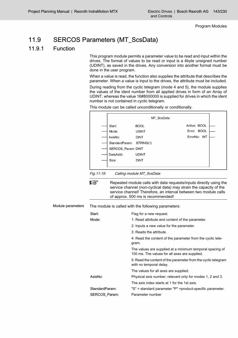
11.9 SERCOS Parameters (MT_ScsData)11.9.1 Function
This program module permits a parameter value to be read and input within thedrives. The format of values to be read or input is a 4byte unsigned number(UDINT), as saved in the drives. Any conversion into another format must bedone in the user program.When a value is read, the function also supplies the attribute that describes theparameter. When a value is input to the drives, the attribute must be included.During reading from the cyclic telegram (mode 4 and 5), the module suppliesthe values of the ident number from all applied drives in form of an Array ofUDINT, whereas the value 16#8000000 is supplied for drives in which the identnumber is not contained in cyclic telegram.This module can be called unconditionally or conditionally.
Fig.11-19: Calling module MT_ScsData
Repeated module calls with data requests/inputs directly using theservice channel (non-cyclical data) may strain the capacity of theservice channel! Therefore, an interval between two module callsof approx. 500 ms is recommended!
The module is called with the following parameters:
Start: Flag for a new request.Mode: 1: Read attribute and content of the parameter.
2: Inputs a new value for the parameter.3: Reads the attribute.4: Read the content of the parameter from the cyclic tele‐gram.The values are supplied at a minimum temporal spacing of100 ms. The values for all axes are supplied.5: Read the content of the parameter from the cyclic telegramwith no temporal delay.The values for all axes are supplied.
AxisNo: Physical axis number; relevant only for modes 1, 2 and 3.The axis index starts at 1 for the 1st axis.
StandardParam: "S" = standard parameter "P" =product-specific parameter.SERCOS_Param: Parameter number
Project Planning Manual | Rexroth IndraMotion MTX Electric Drivesand Controls
| Bosch Rexroth AG 143/230
Program Modules
Module parameters
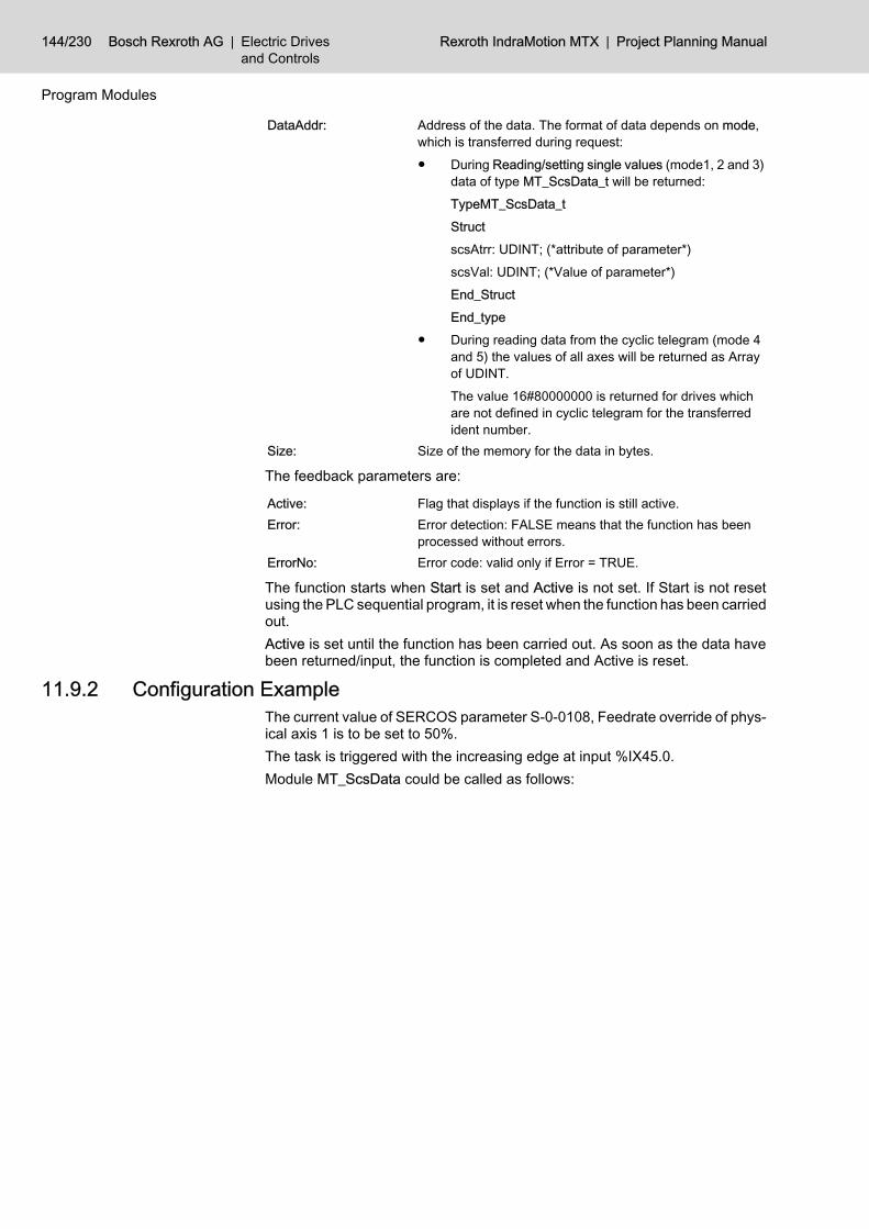
DataAddr: Address of the data. The format of data depends on mode,which is transferred during request:● During Reading/setting single values (mode1, 2 and 3)
data of type MT_ScsData_t will be returned:TypeMT_ScsData_tStructscsAtrr: UDINT; (*attribute of parameter*)scsVal: UDINT; (*Value of parameter*)End_StructEnd_type
● During reading data from the cyclic telegram (mode 4and 5) the values of all axes will be returned as Arrayof UDINT.The value 16#80000000 is returned for drives whichare not defined in cyclic telegram for the transferredident number.
Size: Size of the memory for the data in bytes.
The feedback parameters are:
Active: Flag that displays if the function is still active.Error: Error detection: FALSE means that the function has been
processed without errors.ErrorNo: Error code: valid only if Error = TRUE.
The function starts when Start is set and Active is not set. If Start is not resetusing the PLC sequential program, it is reset when the function has been carriedout.Active is set until the function has been carried out. As soon as the data havebeen returned/input, the function is completed and Active is reset.
11.9.2 Configuration ExampleThe current value of SERCOS parameter S-0-0108, Feedrate override of phys‐ical axis 1 is to be set to 50%.The task is triggered with the increasing edge at input %IX45.0.Module MT_ScsData could be called as follows:
144/230 Bosch Rexroth AG | Electric Drivesand Controls
Rexroth IndraMotion MTX | Project Planning Manual
Program Modules
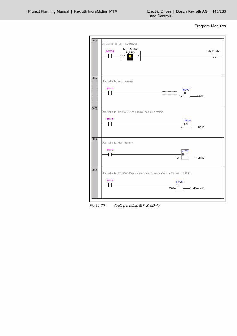
Fig.11-20: Calling module MT_ScsData
Project Planning Manual | Rexroth IndraMotion MTX Electric Drivesand Controls
| Bosch Rexroth AG 145/230
Program Modules
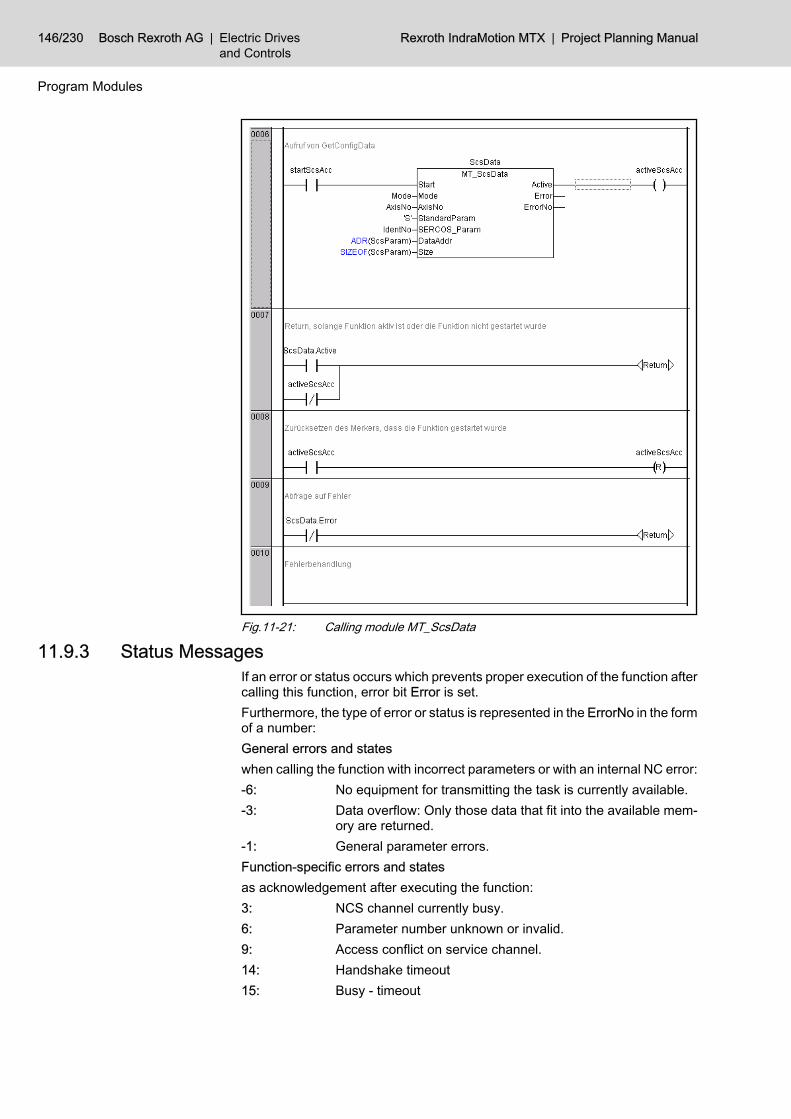
Fig.11-21: Calling module MT_ScsData
11.9.3 Status MessagesIf an error or status occurs which prevents proper execution of the function aftercalling this function, error bit Error is set.Furthermore, the type of error or status is represented in the ErrorNo in the formof a number:General errors and stateswhen calling the function with incorrect parameters or with an internal NC error:-6: No equipment for transmitting the task is currently available.-3: Data overflow: Only those data that fit into the available mem‐
ory are returned.-1: General parameter errors.Function-specific errors and statesas acknowledgement after executing the function:3: NCS channel currently busy.6: Parameter number unknown or invalid.9: Access conflict on service channel.14: Handshake timeout15: Busy - timeout
146/230 Bosch Rexroth AG | Electric Drivesand Controls
Rexroth IndraMotion MTX | Project Planning Manual
Program Modules
22: Transmitted datum too short.23: Transmitted datum too long.24: Element cannot be changed.25: Element cannot be changed at the moment (incorrect start-up
phase).26: Date smaller than minimum value.27: Date larger than maximum value.28: Invalid operating datum (e.g. bit combination).29: SERCOS ring currently not available (startup).30: Incorrect attribute received31: Invalid or non-SERCOS (dummy) system axis.33: Data length exceeds size of service container.40: Max. number of simultaneously active commands exceeded.41: Command change bit timeout.50: Conversion error (conversion to SERCOS representation or
vice versa).500: System axis not available as drive.501: Configuration error (system axis No. and axis No. in ring are
inconsistent).503: 503: invalid SERCOS phase for the function requested.
11.10 Editing Tool Lists (MT_P_DbRecList)11.10.1 Function
Only in connection with "old" tool database tables that are not XML-based.Module "MT_DbRecList" must be used for XML-based tables.
This program module makes it possible to request or delete a list of tool datarecords.● Searching for tool data records
To search for tool data records, up to 7 search criteria, each linked by logicAND operators, may be used. If fewer than 7 search criteria are used, 0must be entered in "Field".
● Deleting tool data recordsA list of data records to be deleted can be input. This module will thendelete each of these data records by overwriting their contents with "0",with the exception of the sector and location numbers. The tool list thatwas requested using certain search criteria can also be used for deleting.The number of data records to be deleted is entered in NofElem.
The module may be called once or repeatedly in a PLC-cycle; calls may beunconditional or conditional.
Project Planning Manual | Rexroth IndraMotion MTX Electric Drivesand Controls
| Bosch Rexroth AG 147/230
Program Modules

Fig.11-22: Calling module MT_P_DbRecListThe module is called with the following parameters:
Start: Flag for a new request.Mode: 1: Searches tool data records from start of table.
2: Search for tool data records starting at StartSector/Start‐Place.3: Delete the content of the tool data records acc. to the list.
TabNo: Table numberStartSector: Sector number from which data records can be sought.
(only for Mode 2)StartPlace: Place number from which data records can be sought.
(only for Mode 2)Conditions: Up to 7 search conditions in the form of a field with the fol‐
lowing structure:Type MT_P_DbRecListCond_tStructField: INT; (* Reference element for the search:0 - search condition is not taken into account1 - Sector2 - Query_int13 - Query_int24 - Query_int35 - Query_int46 - Query_string7 - Query_bitfield *)Value: INT; (* Reference element for the search at Field = 1- 5 *)End_structEnd_type
CondString: Reference string for the search at field = 6 Query_stringCondMask: Bit mask only for Field = 7 Query_bitfield
148/230 Bosch Rexroth AG | Electric Drivesand Controls
Rexroth IndraMotion MTX | Project Planning Manual
Program Modules
Module parameters

DestAddr: Address of the data in the form of a field with the followingstructure:Type MT_P_DbRecListEntryStructSector: INT;Place: INT;End_structEnd_type
Size: Size of the memory for the data in bytes.
The feedback parameters are:
Active: Flag that displays if the function is still active.Error: Error detection: FALSE means that the function has been
processed without errors.ErrorNo: Error code: valid only if Error = TRUE.NofElem: Number of returned elements
The function starts when Start is set and Active is not set. If Start is not resetusing the PLC sequential program, it is reset when the function has been carriedout.Active is set until the function has been carried out. As soon as the data havebeen returned, the function is completed and Active is reset.Search term:The following values may be entered for selecting a search term:
0 Ignore search term
1 Sector
2 Tool number (query_int 1)
3 Duplo number (query_int 2)
4 (query_int 3)
5 (query_int 4)
6 Tool name (query_string)
7 Tool identification (bitfield)
Fig.11-23: Selection of search term
11.10.2 Configuration ExampleA search is to be conducted in the list of all tools with tool number 123 locatedin the magazine (sector 2) and whose tool life has expired.The task is triggered with the increasing edge at input %IX40.0.Module MT_P_DbRecList could be called as follows:
Project Planning Manual | Rexroth IndraMotion MTX Electric Drivesand Controls
| Bosch Rexroth AG 149/230
Program Modules

Fig.11-24: Calling module MT_P_DbRecList
150/230 Bosch Rexroth AG | Electric Drivesand Controls
Rexroth IndraMotion MTX | Project Planning Manual
Program Modules

Fig.11-25: Calling module MT_P_DbRecList
11.10.3 Status MessagesIf an error or status occurs which prevents proper execution of the function aftercalling this function, error bit Error is set.Furthermore, the type of error or status is represented in the ErrorNo in the formof a number:General errors and stateswhen calling the function with incorrect parameters or with an internal NC error:-6: No equipment for transmitting the task is currently available.-3: Data overflow: Only those data that fit into the available mem‐
ory are returned.-1: General parameter errors.Function-specific errors and statesas acknowledgement after executing the function:68: Tool table is empty.1002: Invalid table number.
Project Planning Manual | Rexroth IndraMotion MTX Electric Drivesand Controls
| Bosch Rexroth AG 151/230
Program Modules

11.11 Editing Data Records (MT_P_DbData)11.11.1 Function
Only in connection with "old" tool database tables that are not XML-based.Module "MT_DbData" must be used for XML-based tables.
This program module offers various functions for reading and changing tooldata.The module may be called once or repeatedly in a PLC-cycle; calls may beunconditional or conditional.
Fig.11-26: Calling module MT_DbDataThe module is called with the following parameters:
Start: Flag for a new requestMode: 1 read tool data
2 read tool data with access lock for other processes3 write tool data4 enable tool data record5 exchange tool data record6 copy tool data record7 delete tool data record8 read in an ASCII file of the tool data9 generate an ASCII file of the tool data
TabNoSrc: Table number (source)SectorSrc: Sector number (source)PlaceSrc: Place number (source)TabNoDest: Table number (destination) [relevant only for modes 5 and 6]SectorDest: Sector number (destination) [relevant only for modes 5 and
6]PlaceDest: Place number (destination) [relevant only for modes 5 and 6]TabName: Table name [relevant only for modes 8 and 9]
152/230 Bosch Rexroth AG | Electric Drivesand Controls
Rexroth IndraMotion MTX | Project Planning Manual
Program Modules
Module parameters
DestAddr: Address of the data.The data are returned as type MT_P_DbData:Type MT_P_DbDataStructSector: INTPlace: INTQuery_int_1: INTQuery_int_2: INTQuery_int_3: INTQuery_int_4: INTQuery_bitfield: INTQuery_int: ARRAY[1...40]OFINTQuery_string: STRING(31)End_structEnd_type
Size: Size of the memory for the data in bytes.
The feedback parameters are:
Active: Flag that displays if the function is still active.Error: Error detection: FALSE means that the function has been
processed without errors.ErrorNo: Error code: valid only if Error = TRUE.
The function starts when Start is set and Active is not set. If Start is not resetusing the PLC sequential program, it is reset when the function has been carriedout.Active is set until the function has been carried out. As soon as the data havebeen returned, the function is completed and Active is reset.
11.11.2 Configuration ExampleThe data of the tool in location 5 of sector 2 of table 1 is to be read while anyfurther access to these data is to be inhibited.The task is triggered with the increasing edge at input %IX41.0.Module MT_P_DbData could be called as follows:
Project Planning Manual | Rexroth IndraMotion MTX Electric Drivesand Controls
| Bosch Rexroth AG 153/230
Program Modules

Fig.11-27: Calling module MT_P_DbData
154/230 Bosch Rexroth AG | Electric Drivesand Controls
Rexroth IndraMotion MTX | Project Planning Manual
Program Modules

Fig.11-28: Calling module MT_P_DbData
11.11.3 Status MessagesIf an error or status occurs which prevents proper execution of the function aftercalling this function, error bit Error is set.Furthermore, the type of error or status is represented in the ErrorNo in the formof a number:General errors and stateswhen calling the function with incorrect parameters or with an internal NC error:-6: No equipment for transmitting the task is currently available.-3: Data overflow: Only those data that fit into the available mem‐
ory are returned.-1: General parameter errors.Function-specific errors and statesas acknowledgement after executing the function:68: Tool table is empty.72: Data record not found.108: The data record locked last has not yet been released.
Project Planning Manual | Rexroth IndraMotion MTX Electric Drivesand Controls
| Bosch Rexroth AG 155/230
Program Modules

115: The data record was not inhibited before it was saved to thedatabase or reenabled.
1002: Invalid table number.
11.12 Edit Data Record Lists (MT_DbRecList)11.12.1 Function
This program module makes it possible to search for data records within a da‐tabase table or to delete data records according to a list.● Searching for data records
To search for data records, up to 12 search criteria, each linked by logicAND operators, may be used. The search conditions that are to be takeninto account are selected using parameter CondMask.
● Deleting data recordsA list of data records to be deleted can be input. This module will thendelete each of these data records by overwriting their contents with "0",with the exception of the sector and location numbers. The list that wasrequested using certain search criteria can also be used for deleting. Thenumber of data records to be deleted is entered in NofElem.
If an error occurs, the index of the field element in which the error occurred isreturned in NofElem.The module may be called once or repeatedly in a PLC-cycle; calls may beunconditional or conditional.
Fig.11-29: Calling module MT_P_DbRecListThe module is called with the following parameters:
Start: Flag for a new request.Mode: 1 search data records from start of table.
2 search for data records starting at K1, K2.3 delete the content of the data records acc. to the list.
ElemPath: Identification of data incl. path information (e.g. "/DBT1").
156/230 Bosch Rexroth AG | Electric Drivesand Controls
Rexroth IndraMotion MTX | Project Planning Manual
Program Modules
Module parameters

Conditions: Search conditions of type MT_DbRecListCond_t:Type MT_DbRecList Cond_tStructK1: INT; Key1K2: INT; Key2SKQ: INT; StringIKQ1: DINT; Integer value 1 (key value)IKQ2: DINT; Integer value 2 (key value)IKQ3: DINT; Integer value 3 (key value)IQ1: DINT; Integer value 1 (no key value)IQ2: DINT; Integer value 2 (no key value)IQ3: DINT; Integer value 3 (no key value)BQ1: DWORD; bitfield 1BQ1_Mask: DWORD; Mask for bit field 1BQ2: DWORD; bitfield 2BQ2_Mask: DWORD; Mask for bit field 2BQ3: DWORD; bitfield 3BQ3_Mask: DWORD; Mask for bit field 3End_structEnd_type
CondMask: Mask for selecting the conditions that are to be used in thesearch:16#00000001: K116#00000002: K216#00000004: SKQ16#00000008: IKQ116#00000010: IKQ216#00000020: IKQ316#00000040: IQ116#00000080: IQ216#00000100: IQ316#00000200: BQ116#00000400: BQ216#00000800: BQ3
Project Planning Manual | Rexroth IndraMotion MTX Electric Drivesand Controls
| Bosch Rexroth AG 157/230
Program Modules

DestAddr: Address of the data in the form of a field with the followingstructure:Type MT_DBT1HdStructK1: INTK2: INTSKQ: STRING(31)IKQ1: DINTIKQ2: DINTIKQ3: DINTIQ1: DINTIQ2: DINTIQ3: DINTBQ1: DWORDBQ2: DWORDBQ3: DWORDEnd_structEnd_type
Size: Size of the memory for the data in bytes.StartK1: In the case of a search with Mode 2 (search starting at K1,
K2), the value for K1, where the search is to be started, isentered here.
StartK2: In the case of a search with Mode 2 (search starting at K1,K2), the value for K2, where the search is to be started, isentered here.
If not all the found elements can be returned for a search becausenot enough memory was provided (AllRecsFound = FALSE), thevalues with which the search can then be continued are returned inStartK1 and StartK2.
NofElem: Only for deleting:Number of elements to be deleted.
The feedback parameters are:
Active: Flag that displays if the function is still active.Error: Error detection: FALSE means that the function has been
processed without errors.ErrorNo: Error code: valid only if Error = TRUE.NofElem: Only for searching:
Number of returned elements.
158/230 Bosch Rexroth AG | Electric Drivesand Controls
Rexroth IndraMotion MTX | Project Planning Manual
Program Modules

AllRecsFound: TRUE:All data records that correspond to the search conditions arereturned.FALSE:More data records exist; due to insufficient memory, thesecan not be returned.
StartK1 / StartK2: If not all the found elements can be returned for a searchbecause not enough memory was provided(AllRecsFound=FALSE), the values with which the searchcan then be continued are returned in StartK1 and StartK2.
NofElem: Search: number of returned elements.Delete: Only in case of an error: Index of the data recordwithin the list where the error occurred. When deleting datarecords, the list is processed starting at the end. Therefore,all the data records between the start and the faulty field el‐ement are not deleted if an error occurs.
The function starts when Start is set and Active is not set. If Start is not resetusing the PLC sequential program, it is reset when the function has been carriedout.Active is set until the function has been carried out. As soon as the data havebeen returned, the function is completed and Active is reset.
11.12.2 Configuration ExampleA search is to be carried out in the list of all tools within tool table DBT1 withduplo number 123 that are located in the magazine (K1=2).The task is triggered with the increasing edge at input %IX40.0.Module MT_DbRecList could be called as follows:
Project Planning Manual | Rexroth IndraMotion MTX Electric Drivesand Controls
| Bosch Rexroth AG 159/230
Program Modules

Fig.11-30: Calling module MT_P_DbRecList
160/230 Bosch Rexroth AG | Electric Drivesand Controls
Rexroth IndraMotion MTX | Project Planning Manual
Program Modules
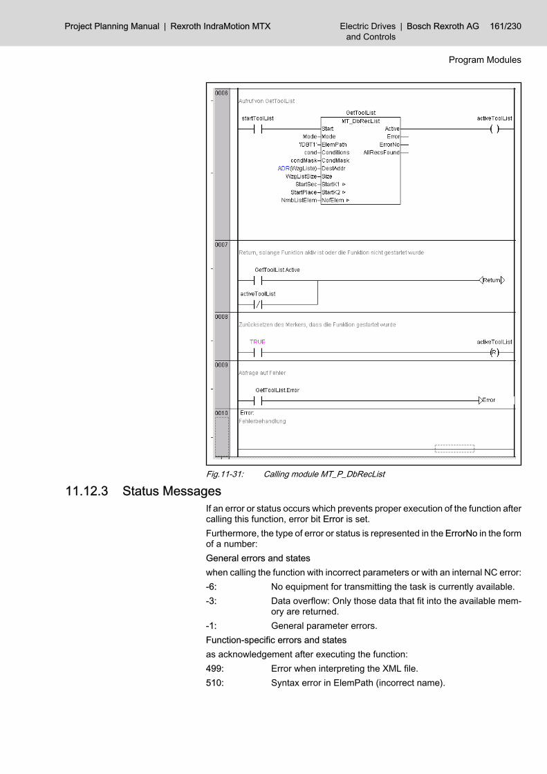
Fig.11-31: Calling module MT_P_DbRecList
11.12.3 Status MessagesIf an error or status occurs which prevents proper execution of the function aftercalling this function, error bit Error is set.Furthermore, the type of error or status is represented in the ErrorNo in the formof a number:General errors and stateswhen calling the function with incorrect parameters or with an internal NC error:-6: No equipment for transmitting the task is currently available.-3: Data overflow: Only those data that fit into the available mem‐
ory are returned.-1: General parameter errors.Function-specific errors and statesas acknowledgement after executing the function:499: Error when interpreting the XML file.510: Syntax error in ElemPath (incorrect name).
Project Planning Manual | Rexroth IndraMotion MTX Electric Drivesand Controls
| Bosch Rexroth AG 161/230
Program Modules

512: Syntax error in ElemPath (incorrect element position).516: The element specified in ElemPath is not declared in schema.518: Element not declared in scheme.519: Transferred data size does not agree with the element size.520: Transferred type ID is not suitable for the element (ElemPath).521: Unknown type ID525: Invalid REAL or LREAL value1001: Error when interpreting the XML file.1002: Database server not ready.1003: The entered name is too long.1007: Transferred data range is too small.1008: Buffer for the path is too small (events).1102: Invalid root element in ElemPath.1104: Data record is already locked.1109: Data record is too large.1112: Invalid search conditions1204: No data records with this key were found.1205: Database is empty.1206: Last locked data record is not released.1208: No locked data record exists.
11.13 Editing Data Records (MT_DbData)11.13.1 Function
This program module offers various functions for reading and changing datarecords (e.g. tool data).Both entire data records and partial data records can be processed. The se‐lection is made using input variable ElemPath (e.g. /DBT1). The data aresupplied in the format in which they were defined on the NC side by the schemefiles. The corresponding structures within the PLC program must be defined inorder to be able to access the files correctly. The corresponding types for thedefault configuration are available in the MTX library (see below).When writing database data, the ID of the type for which the variable is definedon the NC side must be defined in TypeId. This is returned when variables ofthis type are read. In the case of multiple write accesses, this ID must be speci‐fied only once before the first access attempt; it can then be transferred duringeach successive access attempt.The module may be called once or repeatedly in a PLC-cycle; calls may beunconditional or conditional.
162/230 Bosch Rexroth AG | Electric Drivesand Controls
Rexroth IndraMotion MTX | Project Planning Manual
Program Modules
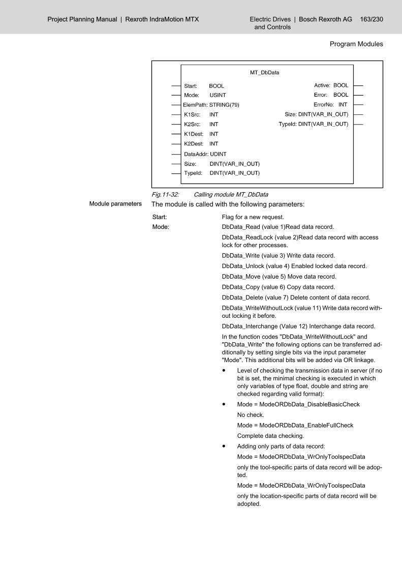
Fig.11-32: Calling module MT_DbDataThe module is called with the following parameters:
Start: Flag for a new request.Mode: DbData_Read (value 1)Read data record.
DbData_ReadLock (value 2)Read data record with accesslock for other processes.DbData_Write (value 3) Write data record.DbData_Unlock (value 4) Enabled locked data record.DbData_Move (value 5) Move data record.DbData_Copy (value 6) Copy data record.DbData_Delete (value 7) Delete content of data record.DbData_WriteWithoutLock (value 11) Write data record with‐out locking it before.DbData_Interchange (Value 12) Interchange data record.In the function codes "DbData_WriteWithoutLock" and"DbData_Write" the following options can be transferred ad‐ditionally by setting single bits via the input parameter"Mode". This additional bits will be added via OR linkage.● Level of checking the transmission data in server (if no
bit is set, the minimal checking is executed in whichonly variables of type float, double and string arechecked regarding valid format):
● Mode = ModeORDbData_DisableBasicCheckNo check.Mode = ModeORDbData_EnableFullCheckComplete data checking.
● Adding only parts of data record:Mode = ModeORDbData_WrOnlyToolspecDataonly the tool-specific parts of data record will be adop‐ted.Mode = ModeORDbData_WrOnlyToolspecDataonly the location-specific parts of data record will beadopted.
Project Planning Manual | Rexroth IndraMotion MTX Electric Drivesand Controls
| Bosch Rexroth AG 163/230
Program Modules
Module parameters

ElemPath: Identification of data incl. path information (e.g. "/DBT1").K1Src: Key 1 (source)K2Src: Key 2 (source)K1Dest: Key 1 (destination) [relevant only for modes 5, 6 and 12]K2Dest: Key 2 (destination) [relevant only for modes 5, 6 and 12]DataAddr: Address of the data.
In the case of access to data records of the default configu‐ration of the tool table, a data record has the following struc‐ture:
Type MT_DBT1Rec_tStructHd: MT_DBT1Hd_tUd: MT_DBT1Ud_tEnd_structEnd_type
Type MT_DBT1Ud_tStructTl: MT_Tl_tEd: ARRAY[1...2]OFMT_Ed_tEnd_structEnd_type
TypeMT_Tl_tStructDescr: STRING(31)LifeU: STRING(3)RemTlLife: REALEnd_structEnd_type
TypeMT_Ed_tStructGeo: MT_Geo_tWear: MT_Wear_tLife: MT_EdLife_tEnd_structEnd_type
164/230 Bosch Rexroth AG | Electric Drivesand Controls
Rexroth IndraMotion MTX | Project Planning Manual
Program Modules
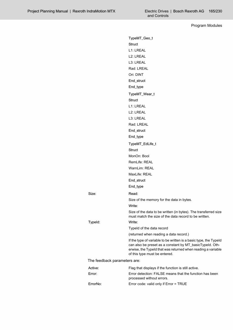
TypeMT_Geo_tStructL1: LREALL2: LREALL3: LREALRad: LREALOri: DINTEnd_structEnd_type
TypeMT_Wear_tStructL1: LREALL2: LREALL3: LREALRad: LREALEnd_structEnd_type
TypeMT_EdLife_tStructMonOn: BoolRemLife: REALWarnLim: REALMaxLife: REALEnd_structEnd_type
Size: Read:Size of the memory for the data in bytes.Write:Size of the data to be written (in bytes). The transferred sizemust match the size of the data record to be written.
TypeId: Write:TypeId of the data record(returned when reading a data record.)If the type of variable to be written is a basic type, the TypeIdcan also be preset as a constant by MT_basicTypeId. Oth‐erwise, the TypeId that was returned when reading a variableof this type must be entered.
The feedback parameters are:
Active: Flag that displays if the function is still active.Error: Error detection: FALSE means that the function has been
processed without errors.ErrorNo: Error code: valid only if Error = TRUE
Project Planning Manual | Rexroth IndraMotion MTX Electric Drivesand Controls
| Bosch Rexroth AG 165/230
Program Modules

Size: Read:Size of the read tool data (in bytes) or, in case of an error,the required memory size.Write:Size of the written tool data (in bytes) or, in case of an error,the correct size of the data record.
TypeId: Read:TypeId of the data record.
The function starts when Start is set and Active is not set. If Start is not resetusing the PLC sequential program, it is reset when the function has been carriedout.Active is set until the function has been carried out. As soon as the data havebeen returned, the function is completed and Active is reset.
11.13.2 Configuration ExampleThe data of the tool in location 5 (Key2) of sector 2 (Key1) of tool databaseDBT1 are to be read while any further access to this data is to be inhibited.The task is triggered with the increasing edge at input %IX41.0.Module MT_DbData could be called as follows:
Fig.11-33: Calling module MT_DbData
166/230 Bosch Rexroth AG | Electric Drivesand Controls
Rexroth IndraMotion MTX | Project Planning Manual
Program Modules

Fig.11-34: Calling module MT_DbData
11.13.3 Status MessagesIf an error or status occurs which prevents proper execution of the function aftercalling this function, error bit Error is set.Furthermore, the type of error or status is represented in the ErrorNo in the formof a number:General errors and stateswhen calling the function with incorrect parameters or with an internal NC error:-6: No equipment for transmitting the task is currently available.-3: Data overflow: Only those data that fit into the available mem‐
ory are returned.-1: General parameter errors.Function-specific errors and statesas acknowledgement after executing the function:499: Error when interpreting the XML file.506: There are more elements than permitted according to maxOc‐
curs.507: The content of the element does not agree with the basic data
type according to the scheme.
Project Planning Manual | Rexroth IndraMotion MTX Electric Drivesand Controls
| Bosch Rexroth AG 167/230
Program Modules

508: The content of the element does not agree with the facet ac‐cording to the scheme.
510: Syntax error in ElemPath (incorrect name)512: Syntax error in ElemPath (incorrect element position).516: The element specified in ElemPath is not declared in schema.518: Element not declared in scheme.519: Transferred data size does not agree with the element size.520: Transferred type ID is not suitable for the element (ElemPath).525: Data set corrupted521: Unknown type ID.1001: Error when interpreting the XML file.1002: Database server not ready.1003: The entered name is too long.1007: Transferred data range is too small.1008: Buffer for the path is too small (events).1102: Invalid root element in ElemPath.1104: Data record is already locked.1109: Data record is too large.1112: Invalid search conditions.1204: No data records with this key were found.1205: Database is empty.1206: Last locked data record is not released.1208: No locked data record exists.
11.14 Save Database Table (MT_DbSave)11.14.1 Function
This program module can be used to partially or totally save a database tablein a file. The following options exist:● the file is first deleted and then the data records are saved (Mode =1)
– or –● the data records are appended to the end of the file (Mode = 2).Parameter SelMask can be input in connection with K1Sel and K2Sel to saveonly certain data records.
Fig.11-35: Save database table
168/230 Bosch Rexroth AG | Electric Drivesand Controls
Rexroth IndraMotion MTX | Project Planning Manual
Program Modules

The module is called with the following parameters:
Start: Flag for a new request.Mode: 1: Save database table in an XML file after previously delet‐
ing the file contents.2: Save database table in an XML file by appending it to thefile contents.
ElemPath: Identification of data incl. Path information (e.g. "/DBT1")SelMask: Information for saving selected data records:
16#00: No selected data record; K1Sel and K2Sel are notconsidered.16#01: Save all data records where K1 corresponds to theinput K1Sel.16#02: Save all data records where K1 and K2 correspondto the input K1Sel and K2Sel.
K1Src: Select the data records using Key1.K2Sel: Select the data records using Key2.Filename: Name of the storage file.
The feedback parameters are:
Active: Flag that displays if the function is still active.Error: Error detection: FALSE means that the function has been
processed without errors.ErrorNo: Error code: valid only if Error = TRUE.
The function starts when Start is set and Active is not set. If Start is not resetusing the PLC sequential program, it is reset when the function has been carriedout.Active is set until the function has been carried out. As soon as the data havebeen returned, the function is completed and Active is reset.
11.14.2 Configuration ExampleAll data records of database table "\DBT1" are to be saved to file"tooltab.dbf"; the file content is to be deleted beforehand (Mode=1).The task is triggered with the increasing edge at input %IX41.0.Module MT_DbSave could be called as follows:
Project Planning Manual | Rexroth IndraMotion MTX Electric Drivesand Controls
| Bosch Rexroth AG 169/230
Program Modules
Module parameters

Fig.11-36: Calling module MT_DbSave
Fig.11-37: Calling module MT_DbSave
170/230 Bosch Rexroth AG | Electric Drivesand Controls
Rexroth IndraMotion MTX | Project Planning Manual
Program Modules

11.14.3 Status MessagesIf an error or status occurs which prevents proper execution of the function aftercalling this function, error bit Error is set.Furthermore, the type of error or status is represented in the ErrorNo in the formof a number:General errors and stateswhen calling the function with incorrect parameters or with an internal NC error:-6: No equipment for transmitting the task is currently available.-3: Data overflow: Only those data that fit into the available mem‐
ory are returned.-1 General parameter errors.Function-specific errors and statesas acknowledgement after executing the function:499: Error when interpreting the XML file.510: Syntax error in ElemPath (incorrect name).512: Syntax error in ElemPath (incorrect element position).516: The element specified in ElemPath is not declared in schema.518: Element not declared in scheme.519: Transferred data size does not agree with the element size.520: Transferred type ID is not suitable for the element (ElemPath).521: Unknown type ID.1001: Error when interpreting the XML file.1002: Database server not ready.1003: The entered name is too long.1007: Transferred data range is too small.1008: Buffer for the path is too small (events).1102: Invalid root element in ElemPath.1104: Data record is already locked.1109: Data record is too large.1112: Invalid search conditions.1204: No data records with this key were found.1205: Database is empty.1206: Last locked data record is not released.1208: No locked data record exists.
11.15 Load Database Table (MT_DbLoad)11.15.1 Function
This program module can be used to partially or totally load a database tablefrom an XML file.Parameter SelMask can be input in connection with K1Sel and K2Sel to loadonly certain data records.
Project Planning Manual | Rexroth IndraMotion MTX Electric Drivesand Controls
| Bosch Rexroth AG 171/230
Program Modules
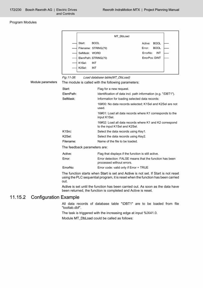
Fig.11-38: Load database table(MT_DbLoad)The module is called with the following parameters:
Start: Flag for a new request.ElemPath: Identification of data incl. path information (e.g. "/DBT1").SelMask: Information for loading selected data records:
16#00: No data records selected; K1Sel and K2Sel are notused.16#01: Load all data records where K1 corresponds to theinput K1Sel.16#02: Load all data records where K1 and K2 correspondto the input K1Sel and K2Sel.
K1Src: Select the data records using Key1.K2Sel: Select the data records using Key2.Filename: Name of the file to be loaded.
The feedback parameters are:
Active: Flag that displays if the function is still active.Error: Error detection: FALSE means that the function has been
processed without errors.ErrorNo: Error code: valid only if Error = TRUE
The function starts when Start is set and Active is not set. If Start is not resetusing the PLC sequential program, it is reset when the function has been carriedout.Active is set until the function has been carried out. As soon as the data havebeen returned, the function is completed and Active is reset.
11.15.2 Configuration ExampleAll data records of database table "\DBT1" are to be loaded from file"tooltab.dbf".The task is triggered with the increasing edge at input %IX41.0.Module MT_DbLoad could be called as follows:
172/230 Bosch Rexroth AG | Electric Drivesand Controls
Rexroth IndraMotion MTX | Project Planning Manual
Program Modules
Module parameters

Fig.11-39: Calling module MT_DbLoad
Fig.11-40: Calling module MT_DbLoad
11.15.3 Status MessagesIf an error or status occurs which prevents proper execution of the function aftercalling this function, error bit Error is set.Furthermore, the type of error or status is represented in the ErrorNo in the formof a number:
Project Planning Manual | Rexroth IndraMotion MTX Electric Drivesand Controls
| Bosch Rexroth AG 173/230
Program Modules
General errors and stateswhen calling the function with incorrect parameters or with an internal NC error:-6: No equipment for transmitting the task is currently available.-3: Data overflow: Only those data that fit into the available mem‐
ory are returned.-1: General parameter errors.Function-specific errors and statesas acknowledgement after executing the function:499: Error when interpreting the XML file.510: Syntax error in ElemPath (incorrect name).512: Syntax error in ElemPath (incorrect element position).516: The element specified in ElemPath is not declared in schema.518: Element not declared in scheme.519: Transferred data size does not agree with the element size.520: Transferred type ID is not suitable for the element (ElemPath).521: Unknown type ID.1001: Error when interpreting the XML file.1002: Database server not ready.1003: The entered name is too long.1007: Transferred data range is too small.1008: Buffer for the path is too small (events).1102: Invalid root element in ElemPath.1104: Data record is already locked.1109: Data record is too large.1112: Invalid search conditions.1204: No data records with this key were found.1205: Database is empty.1206: Last locked data record is not released.1208: No locked data record exists.
11.16 Tool Correction (MT_TCorr)11.16.1 Function
This program module allows to set correction values. A maximum of 16 cor‐rections can be transferred with one call.The external tool corrections are activated using G function "G47 ED x" (x = 1- 16) and deactivated using G48.
The correction values become active only in the next program blockto be prepared.
If the correction values are to become active immediately after their input, NCblock preparation must be suspended (e.g. by WAIT or Block transfer inhibit)or the NC blocks that have already been prepared must be prepared again (byCancel distance to go).This module can be called unconditionally or conditionally.
174/230 Bosch Rexroth AG | Electric Drivesand Controls
Rexroth IndraMotion MTX | Project Planning Manual
Program Modules

Fig.11-41: Tool correction(MT_TCorr)The module is called with the following parameters:
Start: Flag for a new request.Chan: Number of the channel in which the correction values apply.CorrType: 1: Correction with 1 radius and 3 length correction values
each, and the edge position.2: Correction with 1 radius and 3 length correction values,the edge position and angles phi, theta and psi.
CorrIndex: Selection of correction: permitted values: 1 - 16.CorrNmb: Number of corrections.DataAddr: Address of the data.
Depending on the correction type, the correction values aretransferred as a field in the following format:
Project Planning Manual | Rexroth IndraMotion MTX Electric Drivesand Controls
| Bosch Rexroth AG 175/230
Program Modules
Module parameters

CorrType 1:Type MT_Geo_tStructLen1: LREALLen2: LREALLen3: LREALRad: LREALOri: DINTEnd_structEnd_type
CorrType 2:Type MT_GeoExtended_tStructLen1: LREALLen2: LREALLen3: LREALRad: LREALOri: DINTPhi: LREALThe: LREALPsi: LREALEnd_structEnd_type
The feedback parameters are:
Active: Flag that displays if the function is still active.Error: Error detection: FALSE means that the function has been
processed without errors.ErrorNo: Error code: valid only if Error = TRUE.
The function starts when Start is set and Active is not set. The correction valuesare transferred to the NC immediately.If Start is not reset using the PLC sequential program, it is reset when the func‐tion has been carried out.Active is set until the NC has acknowledged the correction input.
11.16.2 Configuration ExampleA radius correction of 3.1234 mm and a length correction of 124 mm is to beinput as the 2nd correction (G47 ED 2) in channel 1 for a milling tool (correctiontype 2).The task is triggered with the increasing edge at input %IX42.0.Module MT_TCorr could be called as follows:
176/230 Bosch Rexroth AG | Electric Drivesand Controls
Rexroth IndraMotion MTX | Project Planning Manual
Program Modules

Fig.11-42: Calling module MT_TCorr
Fig.11-43: Calling module MT_TCorr
Project Planning Manual | Rexroth IndraMotion MTX Electric Drivesand Controls
| Bosch Rexroth AG 177/230
Program Modules

11.16.3 Status MessagesIf an error or status occurs which prevents proper execution of the function aftercalling this function, error bit Error is set.Furthermore, the type of error or status is represented in the ErrorNo in the formof a number:General errors and stateswhen calling the function with incorrect parameters or with an internal NC error:-6: No equipment for transmitting the task is currently available.-3: Data overflow: Only those data that fit into the available mem‐
ory are returned.-1: General parameter errors.Function-specific errors and statesas acknowledgement after executing the function:1: Illegal number of channels.19: Invalid correction index.20: Max. number of corrections exceeded (may be displayed with
the correction index).21: Invalid type of correction.22: Invalid tool edge position.
11.17 Read/Write of Perm. CPL Variables (MT_CplData)11.17.1 Function
This program module supplies the valid value at the time of query of a perma‐nent CPL variable, or can write this CPL variable.This module can be called unconditionally or conditionally.The module does not perform any type conversion. Source and target data typemust be identical.For accessing CPL variables with type conversion, module MT_CplDataConvis available.
Fig.11-44: Calling module MT_CplDataThe module is called with the following parameters:
178/230 Bosch Rexroth AG | Electric Drivesand Controls
Rexroth IndraMotion MTX | Project Planning Manual
Program Modules
Module parameters

Start: Flag for a new request.Chan: Desired channel number.Mode: 0: Read a CPL value.
1: Write a CPL value.VarName: Name of CPL variable.VarType: Type definition of CPL variable:
0 int1 float2 double3 boolean4 char
DestAddr: Address of the data.Size: Size of the memory for the data in bytes.Index1: Field index 1 (only for fields).Index2: Field index 2 (only for two-dimensional fields).NofElem: Write: Number of the predefined values.
The feedback parameters are:
Active: Flag that displays if the function is still active.Error: Error detection: FALSE means that the function has been
processed without errors.ErrorNo: Error code: valid only if Error = TRUE.NofElem: Read: Number of the read values.
The function starts when Start is set and Active is not set. If Start is not resetusing the PLC sequential program, it is reset when the function has been carriedout.Active is set until the function has been carried out. As soon as the data havebeen returned, the function is completed and Active is reset.
11.17.2 Configuration ExampleCPL variable "@Tool location" of type Integer is to be read out in channel 1.The task is triggered with the increasing edge at input %IX42.5.Module MT_CplData could be called as follows:
Project Planning Manual | Rexroth IndraMotion MTX Electric Drivesand Controls
| Bosch Rexroth AG 179/230
Program Modules

Fig.11-45: Calling MT_CplData
Fig.11-46: Calling MT_CplData Graphic
11.17.3 Status MessagesIf an error or status occurs which prevents proper execution of the function aftercalling this function, error bit Error is set.Furthermore, the type of error or status is represented in the ErrorNo in the formof a number:General errors and stateswhen calling the function with incorrect parameters or with an internal NC error:-6: No equipment for transmitting the task is currently available.-3: Data overflow: Only those data that fit into the available mem‐
ory are returned.-1: General parameter errors.
180/230 Bosch Rexroth AG | Electric Drivesand Controls
Rexroth IndraMotion MTX | Project Planning Manual
Program Modules

Function-specific errors and statesas acknowledgement after executing the function:1: variable not found.2: Different variable type.3: Field index faulty.4: Variable type does not exist.
11.18 Read/Write of Perm. CPL Variables with Type Conversion(MT_CplData)
11.18.1 FunctionThis program module supplies the value of a permanent CPL variable that isvalid at the time of the query or can describe this CPL variable. CPL and PLCvariable may be of different data types.The module performs a conversion between different data types. Any loss ofinformation or value range overflow is not indicated.This module can be called unconditionally or conditionally.
Fig.11-47: Calling module MT_CplDataConvThe module is called with the following parameters:
Start: Flag for a new request.Chan: Desired channel number.Mode: 0: Read a CPL value.
1: Write a CPL value.VarName: Name of CPL variable.
Project Planning Manual | Rexroth IndraMotion MTX Electric Drivesand Controls
| Bosch Rexroth AG 181/230
Program Modules
Module parameters

IECType: Type definition of PLC variable:IEC_DINT (0) DINTIEC_REAL (1) REALIEC_LREAL (2) LREALIEC_BOOL (3) BOOLIEC_SINT (4) SINTIEC_INT (5) INTIEC_UDINT (6) UDINTIEC_DWORD (7) DWORDIEC_USINT (8) USINTIEC_BYTE (9) BYTEIEC_STRING (10) STRINGIEC_UINT (11) UINTIEC_WORD (12) WORD
CPLType: Type definition of CPL variable:CPL_INT (0) intCPL_REAL (1) floatCPL_LREAL (2) doubleCPL_BOOL (3) booleanCPL_CHAR (4) char
DestAddr: Address of the data.Size: Size of the memory for the data in bytes.Index1: Field index 1 (only for fields).Index2: Field index 2 (only for two-dimensional fields).NofElem: Write: Number of the predefined values.
The feedback parameters are:
Active: Flag that displays if the function is still active.Error: Error detection: FALSE means that the function has been
processed without errors.ErrorNo: Error code: valid only if Error = TRUE.NofElem: Read: Number of the read values.
The function starts when Start is set and Active is not set. If Start is not resetusing the PLC sequential program, it is reset when the function has been carriedout.Active is set until the function has been carried out. As soon as the data havebeen returned, the function is completed and Active is reset.
11.18.2 Configuration ExampleCPL variable "@Feed_X" of type Integer is to be read out in channel 1. On thePLC side, the value is required in real format.The task is triggered with the increasing edge at input %IX42.5.Module MT_CplDataConv could be called as follows:
182/230 Bosch Rexroth AG | Electric Drivesand Controls
Rexroth IndraMotion MTX | Project Planning Manual
Program Modules

Fig.11-48: Calling MT_CplDataConv
11.18.3 Status MessagesIf an error or status occurs which prevents proper execution of the function aftercalling this function, error bit Error is set. Furthermore, the type of error or statusis represented in the ErrorNo in the form of a number:General errors and stateswhen calling the function with incorrect parameters or with an internal NC error:-6: No equipment for transmitting the task is currently available.-3: Data overflow: Only those data that fit into the available mem‐
ory are returned.-1: General parameter errors.Function-specific errors and statesas acknowledgement after executing the function:1: variable not found.2: Different variable type.3: Field index faulty.4: Variable type does not exist.
11.19 Read System Data (MT_SD_RD)11.19.1 Function
The Read system data module permits any system data to be read. Both entirevariables and partial variables can be read. The selection is made using inputvariable XPath(e.g. /VAR_1). The data are supplied in the format in which they
Project Planning Manual | Rexroth IndraMotion MTX Electric Drivesand Controls
| Bosch Rexroth AG 183/230
Program Modules

were defined on the NC side by the scheme files. The corresponding structureswithin the PLC program must be defined in order to be able to access the filescorrectly.Restrictions:● No complete arrays can be read on the lowermost level (e.g. /ArrayOfInts).
On the other hand, complete arrays that are subelements of a systemvariable can be read (e.g. /ArrayOfInts).
● The size of the requested data is limited to 4 kB.Several instances of the module can be called within one PLC cycle.
Fig.11-49: Calling module MT_SD_RDThe module is called with the following parameters:
Start: Flag for a new request.A new request is executed when Start =TRUE and Active =FALSE.
XPath: Identification of system data incl. path information (e.g. "/Var_1").
DataAddr: Address of the data.The data must be supplied in the format in which they weredefined on the NC side by the scheme files.
Size: Max. size of the data range for the requested data in bytes(SIZEOF( <variable>)).
The feedback parameters are:
Active: Flag that displays if the function is still active.Error: Error detection: FALSE means that the function has been
processed without errors.ErrorNo: Error code: valid only if Error = TRUE.Size: Size of the requested system data (in bytes).TypeId: Type ID of the system datum. This ID must be defined when
writing system data.
The function starts when the Start bit is set and Active is not set. If Bit Start isnot reset using the PLC sequential program, it is reset when the function hasbeen carried out.Active is set for the status until the function has been carried out. As soon asthe data have been returned, the function is completed and Active is reset.
11.19.2 Configuration ExampleThe data of system datum "/Var_1" are to be read.The task is started with the increasing edge at input I43.0.
184/230 Bosch Rexroth AG | Electric Drivesand Controls
Rexroth IndraMotion MTX | Project Planning Manual
Program Modules
Module parameters

Module MT_SD_Rd could be called as follows:
Fig.11-50: Calling module MT_SD_Rd
11.19.3 Status MessagesGeneral errors and stateswhen calling the function with incorrect parameters or with an internal NC error:-6: No equipment for transmitting the task is currently available.Function-specific errors and statesas acknowledgement after executing the function:1: Error within XML-Lib.502: Internal error of the XML server.
Project Planning Manual | Rexroth IndraMotion MTX Electric Drivesand Controls
| Bosch Rexroth AG 185/230
Program Modules

507: The content of the element does not agree with the basic datatype according to the scheme.
508: The content of the element does not agree with the facet ac‐cording to the scheme.
509: Internal error during validating.510: Syntax error in the path string.511: Segment path is not located within root path (internal).512: Element position not permitted according to schema (path).513: An element specified via path cannot be generated.514: The element specified using Path cannot be deleted.515: The element specified via Path does not exist in the XML files.516: The element specified via Path is not declared in the schema.517: The last element in path is not identical with the first element
in data.518: The element of the XML file or XML string is not declared in the
schema.519: The data size does not fit the specified element.520: The data type does not fit the specified element.521: Too much binary files were requested.522: Unknown data type.523: Invalid data size.524: Unknown root element.4001: Internal error of the XML server.4004: Data buffer too small.4101: Invalid mode (internal).4102: Invalid Xpath.
11.20 Write System Data (MT_SD_WR)11.20.1 Function
This program module allows system data to be written.Both entire variables and partial variables can be written. The selection is madeusing input variable XPath(e.g. /VAR_1). The data must be transferred in theformat in which they were defined on the NC side by the scheme files; the sizein Size must also match the type size.The ID of the type for which the variable is defined on the NC side must bedefined in TypeId. This is returned when variables of this type are read. In thecase of multiple write accesses, this ID must be specified only once before thefirst access attempt; it can then be transferred during each successive accessattempt.Restrictions:● No complete arrays can be written on the lowermost level (e.g. /ArrayO‐
fInts). On the other hand, complete arrays that are subelements of asystem variable can be written (e.g. /ArrayOfInts ).
● The size of the requested data is limited to 4 kB.Several instances of the module can be called within one PLC cycle.
186/230 Bosch Rexroth AG | Electric Drivesand Controls
Rexroth IndraMotion MTX | Project Planning Manual
Program Modules
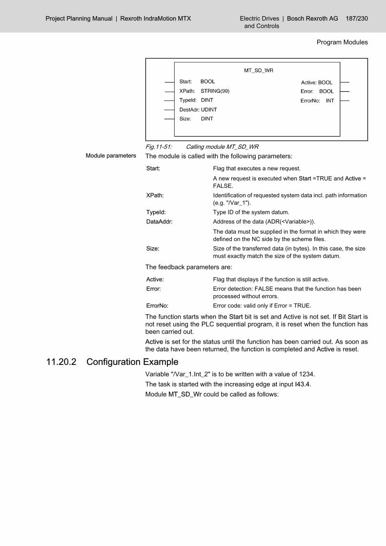
Fig.11-51: Calling module MT_SD_WRThe module is called with the following parameters:
Start: Flag that executes a new request.A new request is executed when Start =TRUE and Active =FALSE.
XPath: Identification of requested system data incl. path information(e.g. "/Var_1").
TypeId: Type ID of the system datum.DataAddr: Address of the data (ADR(<Variable>)).
The data must be supplied in the format in which they weredefined on the NC side by the scheme files.
Size: Size of the transferred data (in bytes). In this case, the sizemust exactly match the size of the system datum.
The feedback parameters are:
Active: Flag that displays if the function is still active.Error: Error detection: FALSE means that the function has been
processed without errors.ErrorNo: Error code: valid only if Error = TRUE.
The function starts when the Start bit is set and Active is not set. If Bit Start isnot reset using the PLC sequential program, it is reset when the function hasbeen carried out.Active is set for the status until the function has been carried out. As soon asthe data have been returned, the function is completed and Active is reset.
11.20.2 Configuration ExampleVariable "/Var_1.Int_2" is to be written with a value of 1234.The task is started with the increasing edge at input I43.4.Module MT_SD_Wr could be called as follows:
Project Planning Manual | Rexroth IndraMotion MTX Electric Drivesand Controls
| Bosch Rexroth AG 187/230
Program Modules
Module parameters
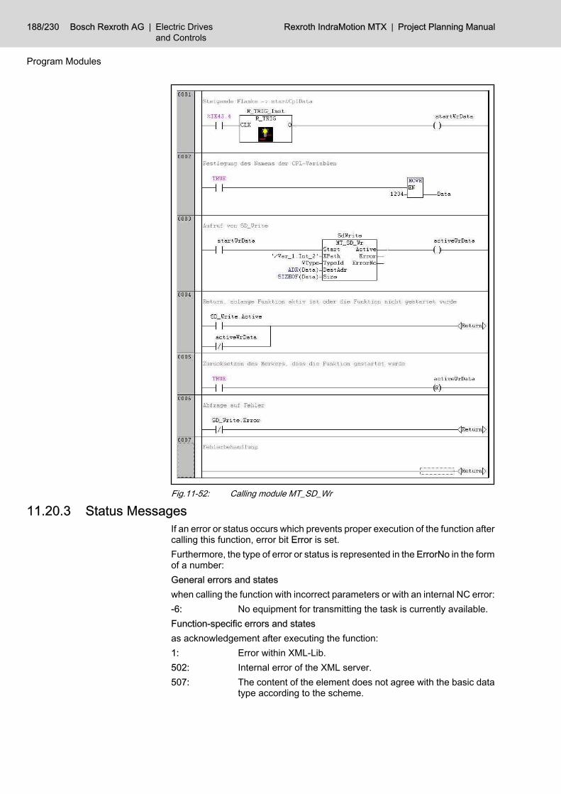
Fig.11-52: Calling module MT_SD_Wr
11.20.3 Status MessagesIf an error or status occurs which prevents proper execution of the function aftercalling this function, error bit Error is set.Furthermore, the type of error or status is represented in the ErrorNo in the formof a number:General errors and stateswhen calling the function with incorrect parameters or with an internal NC error:-6: No equipment for transmitting the task is currently available.Function-specific errors and statesas acknowledgement after executing the function:1: Error within XML-Lib.502: Internal error of the XML server.507: The content of the element does not agree with the basic data
type according to the scheme.
188/230 Bosch Rexroth AG | Electric Drivesand Controls
Rexroth IndraMotion MTX | Project Planning Manual
Program Modules

508: The content of the element does not agree with the facet ac‐cording to the scheme.
509: Internal error during validating.510: Syntax error in the path string.511: Segment path is not located within root path (internal).512: Element position not permitted according to schema (path).513: An element specified via path cannot be generated.514: The element specified using Path cannot be deleted.515: The element specified via Path does not exist in the XML files.516: The element specified via Path is not declared in the schema.517: The last element in path is not identical with the first element
in data.518: The element of the XML file or XML string is not declared in the
schema.519: The data size does not fit the specified element.520: The data type does not fit the specified element.521: Too much binary files were requested.522: Unknown data type.523: Invalid data size.524: Unknown root element.4001: Internal error of the XML server.4004: Data buffer too small.4101: Invalid mode (internal).4102: Invalid Xpath.
11.21 Read Diagnostics Data (MT_DiagCode)11.21.1 General
The function block" MT_DiagCode" provides an image of the content of the NCerror and message data base. The diagnostics messages can be restricted torelevant processing channels and/or relevant message classes via a respectiveinput switching.A diagnostics entry is represented using a structure with information on:● Date● Time● Error class● Diagnostics number.The user provides the FB with a memory for a list of these structures includingthe number of list elements The FB enters the diagnostics entries in decreasingtemporal sequence (the latest one first) in the list. If the list provided by the useris too small for the errors already occurred, all errors outside the list are notvisible for the user. A message regarding new messages and their number isgiven at the output by the FB. Please note that the diagnostics number is uniqueregardless the diagnostics classes except the MSD messages. MSD messageshave the message number projected in the PLC (bit position). NC program anddrive diagnostics are represented using one or more collected diagnostics
Project Planning Manual | Rexroth IndraMotion MTX Electric Drivesand Controls
| Bosch Rexroth AG 189/230
Program Modules

numbers respectively in the NC. Distinguishing between single NC program ordrive diagnostics is therefore not possible.
Fig.11-53: Calling module MT_DiagCode
11.21.2 Module ParametersThe module is called with the following parameters:
Enable: Activation inputAll input parameters are applied at this in‐put in case of an increasing edge.
Channel: Filter for processing channels:Bit 0 = 1 channel-dependent diagnosticsmessagesBit m = 1 (1<=m<=n)Activates the diagnostics for channel m,n: Number of channels in the system
190/230 Bosch Rexroth AG | Electric Drivesand Controls
Rexroth IndraMotion MTX | Project Planning Manual
Program Modules
Classes: Filter for message classes:16#00000001 - major system error16#00000002 - minor system error16#00000004 - drive error16#00000008 - interpolation error16#00000010 - hardware error16#00000020 - ICL error16#00000040 - part program error16#00000080 - CPL error16#00000100 - BOF error16#00000020 - DNC error16#00000400 - Input/output error16#00000800 - machine error16#00001000 - core system warnings16#00002000 - Periphery warning16#00004000 - interface warning16#00008000 - runtime warning16#00010000 - runtime note16#00020000 - DNC note16#00040000 - user note16#00080000 - General note16#00100000 - diagnostics note16#00200000 - machine warning16#00400000 - machine note
DataAddr: Pointer on one or more structures of theMT_DIAGCODE_DATA type.The data structures are filled by the FB withthe diagnostics information.The content of the diagnostics structures isonly valid if the NewData is TRUE.
Size: Size of the memory in bytes in the De‐stAddr
inOperation: Signalizes via TRUE that the block moni‐tors the internal diagnostics database re‐garding changes.The output is set in case of error(Error=TRUE) or in case of deactivation ofthe block via Enable=FALSE (after com‐pletion of ta possible running reading proc‐ess) to FALSE.
Error: Signalizes error states in the block viaTRUE.More exact diagnostics are possible via Er‐rorID and ErrorIdent.
ErrorID: Rough error description
Project Planning Manual | Rexroth IndraMotion MTX Electric Drivesand Controls
| Bosch Rexroth AG 191/230
Program Modules

ErrorIdent: Detailed error description (for future up‐grading)
NewData: Signalizes via TRUE that new diagnosticsmessages occurred or diagnostics mes‐sages were delete considering the filtercriteria (channel and classes): the contentof the memory addresses by DataAddr hasbeen changed.
NofResults: Number of diagnostics data sets in the Da‐taAddr.Value is only valid if DataAddr = TRUE.
Definition of the MT_DIAGCODE_DATA structure:Program:
STRUCT DateTime :DATE_AND_TIME; //Date and time of the message in UTC Chan :UINT; //Channel in which the diagnostics message occurred Class :UDINT; //Diagnostics class Number :DINT; //Diagnostics numberEND_STRUCT
11.21.3 Status MessagesIf an error or status occurs which prevents proper execution of the function aftercalling this function, error bit Error is set. Furthermore, the type of error or statusis represented in the ErrorNo in the form of a number:● 6 - Parameter error● -2 - internal error
11.21.4 Configuration ExampleAll diagnostics messages of channel 1 and all channel-independent messagescan be monitored continiously. The memory provided for accepting diagnosticsinformation has a size of 32 structure elements. If the content of the diagnosticsmemory changes, it is copied for further processing.
Fig.11-54: Configuration Example
192/230 Bosch Rexroth AG | Electric Drivesand Controls
Rexroth IndraMotion MTX | Project Planning Manual
Program Modules

11.22 Read Diagnostics Data (MT_DiagText)11.22.1 General
The function block MT_DiagText provides an image of the content of the NCerror and message data base. The diagnostics messages can be restricted torelevant processing channels and/or relevant message classes via a respectiveinput switching. In contrast to the function block MT_DiagCode, the diagnosticstext are also supplied.The language-dependent text files have to be loaded as UTF8 format in thedirectory "text" of the user eeprom.A diagnostics entry is represented using a structure with information on:● Date, time● Channel● Error class● Diagnostics number● Diagnostics text.The user provides the FB with a memory for a list of these structures includingthe number of list elements The FB enters the diagnostics entries in decreasingtemporal sequence (the latest one first) in the list. If the list provided by the useris too small for the errors already occurred, all errors outside the list are notvisible for the user. A message regarding number of the new messages andgiven at the output by the FB. Please note that the diagnostics number is uniqueregardless the diagnostics classes except the MSD messages. MSD messageshave the message number projected in the PLC (bit position). NC program anddrive diagnostics are represented using one or more collected diagnosticsnumbers respectively in the NC. Distinguishing between single NC program ordrive diagnostics is therefore not possible.
Fig.11-55: Calling module MT_DiagTextA maximum of three instances of the FB can be created for PLC each task.
11.22.2 Module ParametersThe module is called with the following parameters:
Project Planning Manual | Rexroth IndraMotion MTX Electric Drivesand Controls
| Bosch Rexroth AG 193/230
Program Modules
Requirement
Restriction

EnableActivation input, all input parameters are ap‐plied at this input in case of an increasingedge.
Channel
Filter for processing channels:Bit 0 = 1 channel-dependent diagnosticsmessagesBit m = 1 (1<=m<=n) activates diagnosticsfor chanel m, n: Number of channels in thesystem
Classes
Filter for message classes:16#00000001 - major system error16#00000002 - minor system error16#00000004 - drive error16#00000008 - interpolation error16#00000010 - hardware error16#00000020 - ICL error16#00000040 - part program error16#00000080 - CPL error16#00000100 - BOF error16#00000020 - DNC error16#00000400 - Input/output error16#00000800 - machine error16#00001000 - core system error16#00002000 - periphery warning16#00004000 - interface warning16#00008000 - runtime warning16#00010000 - runtime note16#00020000 - DNC note16#00040000 - user note16#00080000 - general note16#00100000 - diagnostics note16#00400000 - machine note16#00400000 - machine note
DataAddr
Pointer on one or more structures of theMT_DIAGTEXT_DATA type. The datastructures are filled by the FB with the diag‐nostics information. The content of the di‐agnostics structures is only valid if theNewData is TRUE.
Size Size of the memory in bytes in the DestAddr
LanguageCountry code for the language selectedE.g. "049" for German
inOperation:
Signalizes via TRUE that the block monitorsthe internal diagnostics database regardingchanges. The output is set in case of error(Error=TRUE) or in case of deactivation ofthe block via Enable=FALSE (after comple‐tion of ta possible running reading process)to FALSE.
194/230 Bosch Rexroth AG | Electric Drivesand Controls
Rexroth IndraMotion MTX | Project Planning Manual
Program Modules

ErrorSignalizes error states in the block viaTRUE. More exact diagnostics are possiblevia ErrorID and ErrorIdent.
ErrorID: Rough error description
ErrorIdent: Detailed error description (for future upgrad‐ing)
NewData
Signalizes via TRUE that new diagnosticsmessages occurred or diagnostics messag‐es were delete considering the filter criteria(channel and classes): the content of thememory addresses by DataAddr has beenchanged.
NofResultsNumber of diagnostics data sets in the Da‐taAddr. Value is only valid if DataAddr =TRUE.
Definition of the MT_DIAGTEXT_DATA structure:Program:STRUCT DateTime :DATE_AND_TIME; //Daten and time of the message in UTC Chan :UINT; //Channel in which the diagnostics message occurred Class :UDINT; //Diagnostics class Number :DINT; //Diagnostics number Message :String(64); //Diagnostics textEND_STRUCT
11.22.3 Status MessagesIf an error or status occurs which prevents proper execution of the function aftercalling this function, error bit "Error" is set. Furthermore, the type of error orstatus is represented in the ErrorNo in the form of a number:● 3 - No more instances of the FB can be created● 6 - Parameter error● -2 - internal error
11.22.4 Projection Examplesee chapter 11.21.4 "Configuration Example" on page 192.
11.23 RIL_CANHilscher11.23.1 Overview
The "RIL_CANHilscher.lib" can be used for MTX systems from versionMTX07VRS onwards.The library can be used in the following systems:
Target components Comment
CMP60 MTXperformance
CMP40 MTXstandard
11.23.2 FB overviewThe library is classified in the following folders:_VersionThe version number is set to 01V01 in the RIL_CANHilscher.lib.<without folder>
Project Planning Manual | Rexroth IndraMotion MTX Electric Drivesand Controls
| Bosch Rexroth AG 195/230
Program Modules
General
Target systems
Classification

Fuction to synchronize several CAN mastersDesignation Type DescriptionVersion_RIL_CANHilscher_01V01 Version ID
IL_CANSync Synchronizing several CANmasters
Fig.11-56: Overview about the function modules and functions in the library
11.23.3 Version_RIL_CANHilscher_01V01A designation of the version is included in the library to ensure version com‐patibility of the firmware. If the names of the version functions are not identical,loading of the application program is refused.
11.23.4 IL_CANSyncSynchronization of several CAN masters is carried out using the function mod‐ule "IL_CANSync".
Fig.11-57: IL_CANSync structure
Name Type Description
VAR_INPUT Execute Bool Function activation; an activated function block cannotbe interrupted.
VAR_OUTPUT Done BOOL Ready message (successful)
Active BOOL Activity display
Error BOOL Ready message (not successful)
ErrorID: ERROR_CODE tbd. (cp. system-comprehensive program guidelines)
ErrorIdent: ERROR_STRUCT Error structure from ErrorTable PB_DP_TABLE
Fig.11-58: IL_CANSync interface
196/230 Bosch Rexroth AG | Electric Drivesand Controls
Rexroth IndraMotion MTX | Project Planning Manual
Program Modules
Function overview
Brief Description
Brief Description
Interface Description

Fig.11-59: Signal time diagram IL_CANSyncThe I/O data exchange between several masters can be synchronized usingthe function module IL_CANSync. If the input signal Execute = True, synchro‐nization is started at the end of the PLC cycle The return values of the functionmodule can be evaluated when starting the next PLC cycle.The library RIL_CommonTypes.lib is necessary for using this function module.
Project Planning Manual | Rexroth IndraMotion MTX Electric Drivesand Controls
| Bosch Rexroth AG 197/230
Program Modules
Signal time diagram
Functional Description

Bosch Rexroth AG | Electric Drivesand Controls
Rexroth IndraMotion MTX | Project Planning Manual

12 Configuration of PLC-Specific Data in IndraWorks12.1 Configuration of Machine Status Display (MSD)12.1.1 General
The machine status display enables the diagnosis of machine errors, warningsand notes and supports the fast removing of faults in the operating procedureon the machine.The MSD diagnoses will be displayed in the MTX-HMI in diagnosis header andin OP9 "Diagnosis". MSD diagnoses can be recorded in the logbook.The corresponding messages will be defined in plaintext in the MSD file"mzatexte.xxx" and activated by setting the corresponding signal on MSD bitinterface in PLC program.
12.1.2 Parameterization of Machine Status Display (MSD)The exchange of MSD signals is cyclically executed between PLC and NC.Select parameter "MachStatDiagCycTime" for the time interval. It should e.g.be set to 300 ms to keep communication load of the system low.
Fig.12-1: MSD cycle time
The cycle time "0" switches off the MSD diagnosis.
12.1.3 Configuration of the MSD Bit InterfaceAccording to the number of machine errors, warnings and notes, the bit inter‐face data types● "qMSD" with up to 2048 or● "qMSD_Ext" with up to 8192different signals can be used.
Project Planning Manual | Rexroth IndraMotion MTX Electric Drivesand Controls
| Bosch Rexroth AG 199/230
Configuration of PLC-Specific Data in IndraWorks

Fig.12-2: Inserting MSD interface signalsThe following settings can be made in the MSD properties dialog (see fig. be‐low):● The identifier for the MSD bit interface can freely be selected. Therefore
the identifier of MSD node below the "CyclicProcessData" node must beclicked via the right mouse button. Now the "Rename" command can beselected in the context menu. We recommend to assume the proposedidentifier "qMSD" or "qMSD_Ext".
● The memory address of the selected data type in bit interface begins andcan freely be selected as long as this does not overlap with other ad‐dresses in bit interface.
200/230 Bosch Rexroth AG | Electric Drivesand Controls
Rexroth IndraMotion MTX | Project Planning Manual
Configuration of PLC-Specific Data in IndraWorks

Fig.12-3: MSD properties dialog
12.1.4 Structure of MSD fileThe MSD file must be stored in the control's root directory "/" or the user FE‐PROM "/usrfep" under the name "mzatexte.xxx". The file name extension"xxx" stands for the used language e.g. 049 for German.The MSD text is divided into main, auxiliary and remedy text. The separation iseffected with a double character "##". Long texts can be continued via character"_" on the line end in the next line.Example:
MSD text
mzatexte.049...(E123, EMERGENCY STOP button on the station is pressed! ## _The EMERGENCY STOP button on the station is still pressed! ## _Not until this EMERGENCY STOP condition is removed, the power _ can beswitched on!)(M124, coolant missing! ## The coolant level has fallen under the minimumlevel _! ##Please fill up coolant if necessary.)...
Project Planning Manual | Rexroth IndraMotion MTX Electric Drivesand Controls
| Bosch Rexroth AG 201/230
Configuration of PLC-Specific Data in IndraWorks

The syntax of MZA definition in file "mzatexte.xxx" is displayed as follows:(<Diagnosis class><Msd number>,<Main text>##<Auxiliary text>##<Remedytext> )
<Diagnosis class> ● E for machine error● W for machine warning● M for machine note
<MSD number> Bit in the structure qMSD [1..2048] or qMSD_Ext [1..8192]and simultaneous message number in the diagnosis.
<Main text> Mostly single-line message text which is also shown in thestatus line.
<Auxiliary text> Auxiliary text for detailed description of diagnosis.<Remedy text> Description for elimination of the occurred failure.
The texts which can not be displayed in the ASCII character set, can be enteredin the UTF8 character coding. A MZA file in UTF8 format must have the hexa‐decimal 3 byte file identification "EFBBBF" on block beginning. The texts willbe transmitted with a maximum length of up to 1000 characters. During utiliza‐tion of UTF8 format, the text length reduces by up to 2/3 of the displayablecharacters corresponding to the coding effort.
12.1.5 Activating the MessagesThe MSD messages will be activated in the PLC by setting the requested bitsignals.Example:
Structured text
qMSD_Ext.MZA_0004:=TRUE;
Resetting the MSD messages must also be programmed in the PLC.Example:
Structured text
qMSD_Ext.MZA_0004:=FALSE;
12.1.6 Additional InformationThe control-internal error database can not absorb unlimited errors.Messages from the MSD area can absorb a maximum of● 16 errors● 16 warnings and● 16 notes.If more messages occur (i.e. for example more than 16 machine errors), onlythe high-prior errors will be saved in the internal error database. The priority isspecified by the message number. Small numbers mean high priority.When messages are deleted, lower-priority ones may "follow on". On whichpoint of time the corresponding message occurs, is not known at the point oftime of "following on", as the time stamp is not saved."Follow on" messages will therefore get the time stamp 1.1.1970 00:00:00.000."Following on" only occurs if more than
202/230 Bosch Rexroth AG | Electric Drivesand Controls
Rexroth IndraMotion MTX | Project Planning Manual
Configuration of PLC-Specific Data in IndraWorks

● at the same time, 16 machine errors● 16 machine warnings or● 16 machine notes at a time.The range of the MSD signals specifies the file "mzatexte.xxx". Only the PLCMSD signals between qMZA(_Ext).MZA_0001 and qMZA(_Ext).MZA_nnnn areevaluated respectively. "nnnn" results from the highest error number(Ennnn,...), warning number- (Wnnnn,…) or notification number (Mnnnn,...)entered in the file "mzatexte.xxx". Signals that are not within the range are ig‐nored. Therefore, transmission time can be saved for signal that are notrequired. Signals within the range and without a text correspondence appearautomatically as machine warning (<No>).
Project Planning Manual | Rexroth IndraMotion MTX Electric Drivesand Controls
| Bosch Rexroth AG 203/230
Configuration of PLC-Specific Data in IndraWorks

Bosch Rexroth AG | Electric Drivesand Controls
Rexroth IndraMotion MTX | Project Planning Manual
13 RIL_ProfibusDP13.1 Overview
Using this library, DPV1 services of the process field bus master (DP masterclass 1) are made available on the one hand and on the other hand, a diagnosisinterface between the process field bus master and the PLC program is estab‐lished.
The sync and freeze control commande are not supported by theMTX.
The function blocks serve for read and write access to acyclic data exchange(DPV1):1. DP_RDREC2. DP_WRRECIn addition, auxiliary functions are available for addressing:1. DP_ADDR2. DP_ID3. DP_SLOT
By means of function blocks, diagnosis information can be obtained. The di‐agnosis is distinguished as follows:1. Slave diagnosis data according to the Profibus DP standard:
"DP_RDIAG" and "DP_RDIAG_EXT"2. General field bus diagnosis: "fbd..."Some of this data is administered in special file types (fields, structures):1. tFBD_BM_INFO2. tFBD_BIT_LIST3. tFBD_KSD_LISTThe function blocks are:1. DP_RDIAG2. DP_RDIAG_EXT3. fbdBaudrateGet4. fbdBmErrorGet5. fbdBmInfoGet6. fbdBmStateGet7. fbdKsdListGet8. fbdPdTypeGet9. fbdPrjSlaveListGet10. fbdSlaveDiagListGet
In the following, the read and write access for acyclic data exchange(DPV1) will be described.
13.2 Selection of the DP masterThe DP masters are distinguished by their sequence in the DP configuration.
Project Planning Manual | Rexroth IndraMotion MTX Electric Drivesand Controls
| Bosch Rexroth AG 205/230
RIL_ProfibusDP
DPV1 services
Diagnosis Information
Addressing
0 .. n(5) number of the DP master in ascending order of the configuration. OnlyDP masters will be counted.128..128+n addressing of the on-board and/or FM slave functionality (for nslaves)
The functions and function blocks which have to access a certain instance ofthe master will be assigned the input parameter "master" of the BYTE type.The functions and function blocks complying with the process field bus guide‐line 2182 dispose of a DWORD parameter "ID" which will be interpreted as aslot handle. It reserves a byte for the selection of the master. The functionDP_SLOT can be used for the generation of the ID parameter.The functions and function blocks using the DWORD parameter "Ident" cangenerate it by means of the DP_ID function.
byte Contents Description
0 MASTER ID of the DP system:Designation of the DP master (or of the on-board slave as well)
1 SEGMENT Number of the DP Segment (0)
2 STATION Number of the DP slave (bus address)
3 SLOT Number of the slot within the slave
Fig.13-1: Slot handle: Parameter "ID"
13.3 The function Version_RIL_ProfibusDP_01V01A designation of the version is included in the library to ensure version com‐patibility of the firmware. If the names of the version functions are not identical,loading of the application program is refused.
13.4 The function DP_ADDRThe function is not distinct. Due to its compatability with the process field busguideline 2182 this function can be loaded but will forward a handle unchanged.
Library Area
RIL_ProfibusDP.lib RIL DPV1-Services
Fig.13-2: Library assignment DP_ADDR
Name Type Description
VAR_INPUT ID DWORD Slot handle
Function value DWORD
Fig.13-3: Interface DP_ADDR
13.5 The function DP_SLOTThis functions adheres to the process field bus guideline 2182. It sets thespecified slot number in the slot handle.
Library Area
RIL_ProfibusDP.lib RIL DPV1-Services
Fig.13-4: Library assignment DP_SLOT
206/230 Bosch Rexroth AG | Electric Drivesand Controls
Rexroth IndraMotion MTX | Project Planning Manual
RIL_ProfibusDP
Application
Brief Description
Brief Description
Interface Description
Brief Description

Name Type Description
VAR_INPUT
ID DWORD Slot handle
SLOT BYTENumber of the slot within the slave(acc. to specification of the slave)(Range of values: 0...254).
Function value DWORD Slot handle
Fig.13-5: Interface DP_SLOT
13.6 The function DP_IDThis function composes an ident handle from the individual components.
Library Area
RIL_ProfibusDP.lib RIL DPV1-Services
Fig.13-6: Library assignment IL_DPIdent
Name Type Description
VAR_INPUT
MASTER BYTE Designation of the DP master (seeabove)
SEGMENT BYTE Number of the DP Segment (0)
STATION BYTE
Number of the DP slave (bus ad‐dress):If the command shall only apply to acertain slave, the bus address of theslave must be entered here (0...125).
SLOT BYTENumber of the slot within the slave(acc. to specification of the slave)(Range of values: 0...254).
Function value DWORD Ident handle
Fig.13-7: Interface DP_ID
The DWORD "Ident" is composed out of the 4 byte values. Such DWORD isrequired as an input parameter for the following function blocks.
13.7 The function block DP_RDRECA read DPV1 acces is carried out with the help of the function blockDP_RDREC. Data exchange on the process field bus DP is acyclical. A targetzone for the process data to be read must be defined via a pointer addressing(POINTER).
Library Area
RIL_ProfibusDP.lib RIL DPV1-Services
Fig.13-8: Library assignment DP_RDREC
Project Planning Manual | Rexroth IndraMotion MTX Electric Drivesand Controls
| Bosch Rexroth AG 207/230
RIL_ProfibusDP
Interface Description
Brief Description
Interface Description
Functional Description
Brief Description
Interface Description

Name Type Description
VAR_INPUT
REQ Bool Function activation; an activated func‐tion block cannot be interrupted.
ID DWORD Ident handle (see function DP_ID)
INDEX INT Index of the process data (field num‐ber)
MLEN UDINTMaximum length of the data to beread; number of the available bytes onthe pointer "REC_PTR"
REC_PTR POINTER TOBYTE
Pointer on data buffer for target data
VAR_OUTPUT
VALID Bool TRUE: New valid data is available
ERROR Bool TRUE: (An) error(s) has/have occur‐red.
BUSY BoolTRUE: The function block is busy. Aslong as BUSY = TRUE, the data can‐not be evaluated.
STATUS DWORD Status last identified
LEN UDINT Length of the process data in byte
Fig.13-9: Interface DP_RDREC
With this, the master (class 1) will access a DP-V1 slave. It will read the datarecord of the slave addressed by the slave address, the slot and the index.Addressing with the slot and the index as well as interpretation of the data isslave-specific and can be found in the relevant documentation of the slave. Theexecution time of the function also depends on the load of the bus and the baudrate set.This function is only possible for slaves participating in the DP bus cycle.
13.8 The function block DP_WRRECA write DPV1 acces is carried out with the help of the function blockDP_WRREC. Data exchange on the process field bus DP is acyclical. Theprocess data to be written will be transferred via pointer addressing (POINTER).
Library Area
RIL_ProfibusDP.lib RIL DPV1-Services
Fig.13-10: Library assignment DP_WRREC
208/230 Bosch Rexroth AG | Electric Drivesand Controls
Rexroth IndraMotion MTX | Project Planning Manual
RIL_ProfibusDP
Functional Description
Brief Description

Name Type Description
VAR_INPUT
REQ Bool Function activation; an activated func‐tion block cannot be interrupted.
ID DWORD Ident handle (see function IL_DPI‐dent)
INDEX INT Index of the process data (field num‐ber)
LEN UDINTMaximum length of the data to beread; number of the available bytes onthe pointer "REC_PTR"
REC_PTR POINTER TOBYTE
Pointer on data buffer for the data
VAR_OUTPUT
DONE Bool TRUE: Call completed
ERROR Bool TRUE: (An) error(s) has/have occur‐red.
BUSY BoolTRUE: The function block is busy. Aslong as BUSY = TRUE, the data can‐not be evaluated.
STATUS DWORD Status last identified
Fig.13-11: Interface signals DP_WRREC
With this, the master (class 1) will access a DP-V1 slave. It will read the datarecord of the slave addressed by the slave address, the slot and the index.Addressing with the slot and the index as well as interpretation of the data isslave-specific and can be found in the relevant documentation of the slave. Theexecution time of the function also depends on the load of the bus and the baudrate set.This function is only possible for slaves participating in the DP bus cycle.
Project Planning Manual | Rexroth IndraMotion MTX Electric Drivesand Controls
| Bosch Rexroth AG 209/230
RIL_ProfibusDP
Interface Description
Functional Description

Bosch Rexroth AG | Electric Drivesand Controls
Rexroth IndraMotion MTX | Project Planning Manual

14 Overview on Interface Signals14.1 Global Output Signals (PLC -> NC)
Bit Symbol. Addr. PLC output signal Bit Symbol. Addr. PLC output signal
0.0 qGen_Reset System control reset 1.0 qGen_StrokeInhibit Stroke inhibit
0.1 qGen_EditInhibit Edit inhibit 1.1 qGen_StrokeReserv Stroke reservation
0.2 qGen_DelErrInfo Clear error info 1.2 qGen_StrokeRel Stroke on
0.3 - res. 1.3 - res.
0.4 - res. 1.4 - res.
0.5 - res. 1.5 - res.
0.6 - res. 1.6 - res.
0.7 - res. 1.7 - res.
2.0 - res. 3.0 - res.
2.1 - res. 3.1 - res.
2.2 - res. 3.2 - res.
2.3 - res. 3.3 - res.
2.4 - res. 3.4 - res.
2.5 - res. 3.5 - res.
2.6 - res. 3.6 - res.
2.7 - res. 3.7 - res.
Fig.14-1: Overview of output signals (PLC → NC)
14.2 Global Input Signals (NC -> PLC)Bit Symbol. Addr. PLC input signal Bit Symbol. Addr. PLC input signal
0.0 - res. 1.0 iGen_StrokeIntend Stroke intended
0.1 iGen_HardwareState Hardware warning 1.1 iGen_NoStroke Stroke is not running
0.2 - res. 1.2 - res.
0.3 - res. 1.3 - res.
0.4 - res. 1.4 - res.
0.5 - res. 1.5 - res.
0.6 - res. 1.6 - res.
0.7 - res. 1.7 - res.
2.0 - res. 3.0 - res.
2.1 - res. 3.1 - res.
2.2 - res. 3.2 - res.
2.3 - res. 3.3 - res.
2.4 - res. 3.4 - res.
2.5 - res. 3.5 - res.
Project Planning Manual | Rexroth IndraMotion MTX Electric Drivesand Controls
| Bosch Rexroth AG 211/230
Overview on Interface Signals
Bit Symbol. Addr. PLC input signal Bit Symbol. Addr. PLC input signal
2.6 - res. 3.6 - res.
2.7 - res. 3.7 - res.
Fig.14-2: Overview of input signals (NC -> PLC)
14.3 Channel-related Output Signals (PLC -> NC)Bit Symbol. Addr. PLC output signal Bit Symbol. Addr. PLC output signal
0.0 qCh_OpModeSel_00 Sel. operating mode forbit 0 1.0 qCh_OpModePlc PLC operating mode
0.1 qCh_OpModeSel_01 Sel. operating mode forbit 1 1.1 qCh_Restart Automatic restart
0.2 qCh_OpModeSel_02 Sel. operating mode forbit 2 1.2 qCh_NCStart Cycle start
0.3 qCh_OpModeSel_03 Sel. operating mode forbit 3 1.3 qCh_TransferLock Read lock
0.4 - res. 1.4 qCh_FeedHold Feed stop
0.5 - res. 1.5 qCh_FeedStop Feed inhibit
0.6 - res. 1.6 - res.
0.7 - res. 1.7 qCh_ReSelOff Autom. reselection off
2.0 qCh_CtrlReset Control reset 3.0 qCh_ASub1 Asynchr. subprogr. 1
2.1 - res. 3.1 qCh_ASub2 Asynchr. subprogr. 2
2.2 qCh_CancDist Cancel distance to go 3.2 qCh_ASub3 Asynchr. subprogr. 3
2.3 qCh_NextBlk Switch to next block 3.3 qCh_ASub4 Asynchr. subprogr. 4
2.4 - res. 3.4 qCh_ASub5 Asynchr. subprogr. 5
2.5 - res. 3.5 qCh_ASub6 Asynchr. subprogr. 6
2.6 qCh_RetCont Return to path 3.6 qCh_ASub7 Asynchr. subprogr. 7
2.7 qCh_Retract Rapid retraction 3.7 qCh_ASub8 Asynchr. subprogr. 8
4.0 qCh_JogPlusWcs WCS manual + 5.0 qCh_BlkSlash Block slash
4.1 qCh_JogMinusWcs WCS manual - 5.1 qCh_OptStop Optional stop
4.2 - res. 5.2 qCh_OptJump Conditional jump
4.3 - res. 5.3 - res.
4.4 qCh_Handw‐SelWcs_00 Select handwheel Bit0 5.4 qCh_RedRap Limit rapid travel
4.5 qCh_Handw‐SelWcs_01
Handwheel selection bit1 5.5 - res.
4.6 qCh_HandwDirWcs Handwheel direction 5.6 - res.
4.7 qCh_HandwPosMode Position handwheel 5.7 qCh_Override100 Override100%
6.0 qCh_Override_00 Override bit 0 7.0 qCh_Override_08 Override bit 8
6.1 qCh_Override_01 Override bit 1 7.1 qCh_Override_09 Override bit 9
6.2 qCh_Override_02 Override bit 2 7.2 qCh_Override_10 Override bit 10
6.3 qCh_Override_03 Override bit 3 7.3 qCh_Override_11 Override bit 11
212/230 Bosch Rexroth AG | Electric Drivesand Controls
Rexroth IndraMotion MTX | Project Planning Manual
Overview on Interface Signals

Bit Symbol. Addr. PLC output signal Bit Symbol. Addr. PLC output signal
6.4 qCh_Override_04 Override bit 4 7.4 qCh_Override_12 Override bit 12
6.5 qCh_Override_05 Override bit 5 7.5 qCh_Override_13 Override bit 13
6.6 qCh_Override_06 Override bit 6 7.6 qCh_Override_14 Override bit 14
6.7 qCh_Override_07 Override bit 7 7.7 qCh_Override_15 Override bit 15
8.0 qCh_Custom1 Customer input 1 9.0 qCh_OnlCorrWcs Online correction re‐lease
8.1 qCh_Custom2 Customer input 2 9.1 qCh_OnlCorrWcsDir Online correction direc‐tion
8.2 qCh_Custom3 Customer input 3 9.2 - res.
8.3 qCh_Custom4 Customer input 4 9.3 - res.
8.4 qCh_Custom5 Customer input 5 9.4 - res.
8.5 qCh_Custom6 Customer input 6 9.5 - res.
8.6 qCh_Custom7 Customer input 7 9.6 qCh_CoordCoupleOff Decoupling
8.7 qCh_Custom8 Customer input 8 9.7 qCh_TangTRotRel TTL release
10.0 - res. 11.0 - res.
10.1 - res. 11.1 - res.
10.2 - res. 11.2 - res.
10.3 - res. 11.3 - res.
10.4 - res. 11.4 - res.
10.5 - res. 11.5 - res.
10.6 - res. 11.6 - res.
10.7 - res. 11.7 - res.
12.0 - res. 13.0 qCH_TestFeed Test feed
12.1 - res. 13.1 qCH_TestRap Test rapid traverse
12.2 - res. 13.2 - res.
12.3 - res. 13.3 - res.
12.4 - res. 13.4 - res.
12.5 - res. 13.5 - res.
12.6 - res. 13.6 - res.
12.7 - res. 13.7 - res.
Fig.14-3: Overview of output signals (PLC → NC)
14.4 Channel-related Input Signals (NC -> PLC)Bit Symbol. Addr. PLC input signal Bit Symbol. Addr. PLC input signal
0.0 iCh_OpMode_00 Sel. operating mode forbit 0 1.0 iCh_DryRun Test mode
0.1 iCh_OpMode_01 Sel. operating mode forbit 1 1.1 iCh_NCReady NC ready
Project Planning Manual | Rexroth IndraMotion MTX Electric Drivesand Controls
| Bosch Rexroth AG 213/230
Overview on Interface Signals

Bit Symbol. Addr. PLC input signal Bit Symbol. Addr. PLC input signal
0.2 iCh_OpMode_02 Sel. operating mode forbit 2 1.2 iCh_ProgRun Program is running
0.3 iCh_OpMode_03 Sel. operating mode forbit 3 1.3 iCh_TransferLockAct Block transfer inhibit ac‐
tive
0.4 res. 1.4 iCh_FeedHoldAct Feed hold active
0.5 res. 1.5 - res.
0.6 res. 1.6 iCh_ProgStopM0 Program stop M0
0.7 res. 1.7 iCh_ProgStopM30 Program stop M30
2.0 iCh_Reset Channel reset 3.0 iCh_ASub1 Asynchr. subprogr. 1
2.1 - res. 3.1 iCh_ASub2 Asynchr. subprogr. 2
2.2 - res. 3.2 iCh_ASub3 Asynchr. subprogr. 3
2.3 - res. 3.3 iCh_ASub4 Asynchr. subprogr. 4
2.4 iCh_RemoveFinish Remove finished 3.4 iCh_ASub5 Asynchr. subprogr. 5
2.5 iCh_ReadyReEnter Ready for re-entry 3.5 iCh_ASub6 Asynchr. subprogr. 6
2.6 iCh_ReEnterAct Reenter active 3.6 iCh_ASub7 Asynchr. subprogr. 7
2.7 - res. 3.7 iCh_ASub8 Asynchr. subprogr. 8
4.0 iCh_State_00 Channel status bit 0 5.0 iCh_BlkSlash Activate block slash
4.1 iCh_State_01 Channel status bit 1 5.1 iCh_OptStop Optional stop activated
4.2 iCh_State_02 Channel status bit 2 5.2 - res.
4.3 iCh_State_03 Channel status bit 3 5.3 iCh_SRunAct NC program restart ac‐tive
4.4 iCh_State_04 Channel status bit 4 5.4 iCh_SRunReEnter Reenter active
4.5 - res. 5.5 iCh_SRunRepos Repositioning active
4.6 - res. 5.6 iCh_Override0 Override 0%
4.7 - res. 5.7 iCh_Override100 Override 100%
6.0 iCh_Cpl01 CPL customer output 1 7.0 iCh_Cpl09 CPL customer output 9
6.1 iCh_Cpl02 CPL customer output 2 7.1 iCh_Cpl10 CPL customer output10
6.2 iCh_Cpl03 CPL customer output 3 7.2 iCh_Cpl11 CPL customer output11
6.3 iCh_Cpl04 CPL customer output 4 7.3 iCh_Cpl12 CPL customer output12
6.4 iCh_Cpl05 CPL customer output 5 7.4 iCh_Cpl13 CPL customer output13
6.5 iCh_Cpl06 CPL customer output 6 7.5 iCh_Cpl14 CPL customer output14
6.6 iCh_Cpl07 CPL customer output 7 7.6 iCh_Cpl15 CPL customer output15
6.7 iCh_Cpl08 CPL customer output 8 7.7 iCh_Cpl16 CPL customer output16
8.0 iCh_Custom1 Customer output 1 9.0 iCh_G0Act Rapid traverse active
214/230 Bosch Rexroth AG | Electric Drivesand Controls
Rexroth IndraMotion MTX | Project Planning Manual
Overview on Interface Signals

Bit Symbol. Addr. PLC input signal Bit Symbol. Addr. PLC input signal
8.1 iCh_Custom2 Customer output 2 9.1 iCh_InPosAct Inpos range 2 active
8.2 iCh_Custom3 Customer output 3 9.2 iCh_G41G141Act G41/G141 active
8.3 iCh_Custom4 Customer output 4 9.3 iCh_G42G142Act G42/G142 active
8.4 iCh_Custom5 Customer output 5 9.4 - res.
8.5 iCh_Custom6 Customer output 6 9.5 - res.
8.6 iCh_Custom7 Customer output 7 9.6 iCh_CoordCoupleAct Coord. Coupling active
8.7 iCh_Custom8 Customer output 8 9.7 iCh_TangTRotCmd Tool rotation (Tang‐Tool)
10.0 iCh_ActFunc01 G70 active 11.0 iCh_ActFunc09 Tool compensation ac‐tive bit 0
10.1 iCh_ActFunc02 Feed 100% active 11.1 iCh_ActFunc10 Tool compensation ac‐tive bit 1
10.2 iCh_ActFunc03 G95 active 11.2 iCh_ActFunc11 Tool compensation ac‐tive bit 2
10.3 iCh_ActFunc04 Axis transformer 2 inac‐tive 11.3 iCh_ActFunc12 Tool compensation ac‐
tive bit 3
10.4 iCh_ActFunc05 Program position active 11.4 iCh_ActFunc13 Tool compensation ac‐tive bit 4
10.5 iCh_ActFunc06 Thread cycle active 11.5 iCh_ActFunc14 not assigned
10.6 iCh_ActFunc07 Tapping without com‐pensating chuck active 11.6 iCh_ActFunc15 not assigned
10.7 iCh_ActFunc08 Thread cutting active 11.7 iCh_ActFunc16 not assigned
12.0 iCh_ActFunc17 not assigned 13.0 iCh_TestFeed Test feed active
12.1 iCh_ActFunc18 G96 active 13.1 iCh_TestRap Test of rapid traverseactive
12.2 iCh_ActFunc19 not assigned 13.2 - res.
12.3 iCh_ActFunc20 not assigned 13.3 - res.
12.4 iCh_ActFunc21 not assigned 13.4 - res.
12.5 iCh_ActFunc22 not assigned 13.5 - res.
12.6 iCh_ActFunc23 not assigned 13.6 - res.
12.7 iCh_ActFunc24 not assigned 13.7 - res.
Fig.14-4: Overview of input signals (NC -> PLC)
14.5 Axis-related of Output Signals (PLC -> NC)Bit Symbol. Addr. PLC output signal Bit Symbol. Addr. PLC output signal
0.0 qAx_OpModeSel_00 Axis mode bit 0 1.0 qAx_TrvLim_00 Limit switch range bit 0
0.1 qAx_OpModeSel_01 Axis mode bit 1 1.1 qAx_TrvLim_01 Limit switch range bit 1
0.2 qAx_JogPlus Manual + 1.2 qAx_SwLimOff Suppress limit switch
0.3 qAx_JogMinus Manual - 1.3 - res.
0.4 qAx_JogInch Schrittmaß in Inch 1.4 - res.
Project Planning Manual | Rexroth IndraMotion MTX Electric Drivesand Controls
| Bosch Rexroth AG 215/230
Overview on Interface Signals
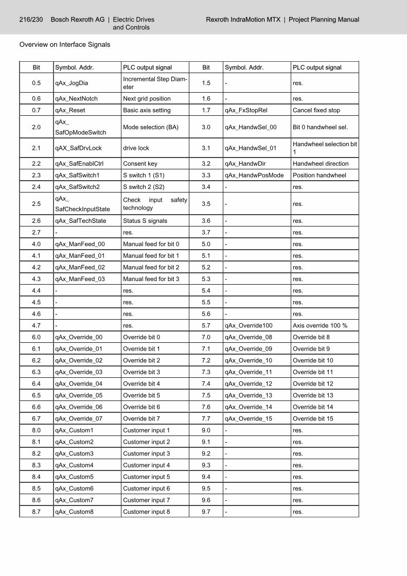
Bit Symbol. Addr. PLC output signal Bit Symbol. Addr. PLC output signal
0.5 qAx_JogDia Incremental Step Diam‐eter 1.5 - res.
0.6 qAx_NextNotch Next grid position 1.6 - res.
0.7 qAx_Reset Basic axis setting 1.7 qAx_FxStopRel Cancel fixed stop
2.0qAx_SafOpModeSwitch
Mode selection (BA) 3.0 qAx_HandwSel_00 Bit 0 handwheel sel.
2.1 qAX_SafDrvLock drive lock 3.1 qAx_HandwSel_01 Handwheel selection bit1
2.2 qAx_SafEnablCtrl Consent key 3.2 qAx_HandwDir Handwheel direction
2.3 qAx_SafSwitch1 S switch 1 (S1) 3.3 qAx_HandwPosMode Position handwheel
2.4 qAx_SafSwitch2 S switch 2 (S2) 3.4 - res.
2.5qAx_SafCheckInputState
Check input safetytechnology 3.5 - res.
2.6 qAx_SafTechState Status S signals 3.6 - res.
2.7 - res. 3.7 - res.
4.0 qAx_ManFeed_00 Manual feed for bit 0 5.0 - res.
4.1 qAx_ManFeed_01 Manual feed for bit 1 5.1 - res.
4.2 qAx_ManFeed_02 Manual feed for bit 2 5.2 - res.
4.3 qAx_ManFeed_03 Manual feed for bit 3 5.3 - res.
4.4 - res. 5.4 - res.
4.5 - res. 5.5 - res.
4.6 - res. 5.6 - res.
4.7 - res. 5.7 qAx_Override100 Axis override 100 %
6.0 qAx_Override_00 Override bit 0 7.0 qAx_Override_08 Override bit 8
6.1 qAx_Override_01 Override bit 1 7.1 qAx_Override_09 Override bit 9
6.2 qAx_Override_02 Override bit 2 7.2 qAx_Override_10 Override bit 10
6.3 qAx_Override_03 Override bit 3 7.3 qAx_Override_11 Override bit 11
6.4 qAx_Override_04 Override bit 4 7.4 qAx_Override_12 Override bit 12
6.5 qAx_Override_05 Override bit 5 7.5 qAx_Override_13 Override bit 13
6.6 qAx_Override_06 Override bit 6 7.6 qAx_Override_14 Override bit 14
6.7 qAx_Override_07 Override bit 7 7.7 qAx_Override_15 Override bit 15
8.0 qAx_Custom1 Customer input 1 9.0 - res.
8.1 qAx_Custom2 Customer input 2 9.1 - res.
8.2 qAx_Custom3 Customer input 3 9.2 - res.
8.3 qAx_Custom4 Customer input 4 9.3 - res.
8.4 qAx_Custom5 Customer input 5 9.4 - res.
8.5 qAx_Custom6 Customer input 6 9.5 - res.
8.6 qAx_Custom7 Customer input 7 9.6 - res.
8.7 qAx_Custom8 Customer input 8 9.7 - res.
216/230 Bosch Rexroth AG | Electric Drivesand Controls
Rexroth IndraMotion MTX | Project Planning Manual
Overview on Interface Signals

Bit Symbol. Addr. PLC output signal Bit Symbol. Addr. PLC output signal
10.0 qAx_TrqErrOff Suppress standstill er‐ror 11.0 qAx_Discharge Axis discharged
10.1 qAx_LagErrOff Suppress coupling er‐ror 11.1 qAx_FrzIpoPos Hold command position
10.2 qAx_MasterPos Gantry in master posi‐tion 11.2 - res.
10.3 qAx_TakeActOffs Take over actual valueoffset 11.3 qAx_TrqLim Torque Reduction
10.4 - res. 11.4 - res.
10.5 - res. 11.5 - res.
10.6 - res. 11.6 qAx_DrvOn Drive on
10.7 - res. 11.7 qAx_DrvLock Feed lock
Fig.14-5: Overview of output signals (PLC → NC)
14.6 Axis-related Input Signals (NC -> PLC)Bit Symbol. Addr. PLC input signal Bit Symbol. Addr. PLC input signal
0.0 iAx_RefKnown Reference point known 1.0 iAx_DistCtrl Axis before end point
0.1 iAx_RefReached Home point reached 1.1 iAx_ProgSpReach Axis speed reached
0.2 iAx_TrvCmd Travel command 1.2 - res.
0.3 iAx_TrvDirNeg Negative travel direc‐tion 1.3 - res.
0.4 iAx_Run Axis running 1.4 - res.
0.5 iAx_InPos Axis in position 1.5 - res.
0.6 iAx_NotchPos Axis on grid position 1.6 iAx_FxStopReached Fixed stop reached
0.7 iAx_Reset Axis is reset 1.7 iAx_FxStopAct Fixed stop active
2.0 iAx_SafOpMode_00 Bit 0 safety mode 3.0 iAx_PosSwitch1 Position switch point 1
2.1 iAx_SafOpMode_01 Bit 1 safety mode 3.1 iAx_PosSwitch2 Position switch point 2
2.2 iAx_SafOpMode_02 Bit 2 safety mode 3.2 iAx_PosSwitch3 Position switch point 3
2.3 iAx_SafOpMode_03 Safety mode bit 3 3.3 iAx_PosSwitch4 Position switch point 4
2.4 iAx_SafStatePos Safe position status 3.4 iAx_PosSwitch5 Position switch point 5
2.5iAx_SafCtrlOutputState
Control status output 3.5 iAx_PosSwitch6 Position switch point 6
2.6 - res. 3.6 iAx_PosSwitch7 Position switch point 7
2.7 - res. 3.7 iAx_PosSwitch8 Position switch point 8
4.0 iAx_ChIndex_00 Channel number bit 0 5.0 - res.
4.1 iAx_ChIndex_01 Channel number bit 1 5.1 - res.
4.2 iAx_ChIndex_02 Channel number bit 2 5.2 - res.
4.3 iAx_ChIndex_03 Channel number bit 3 5.3 - res.
4.4 - res. 5.4 - res.
Project Planning Manual | Rexroth IndraMotion MTX Electric Drivesand Controls
| Bosch Rexroth AG 217/230
Overview on Interface Signals

Bit Symbol. Addr. PLC input signal Bit Symbol. Addr. PLC input signal
4.5 - res. 5.5 - res.
4.6 - res. 5.6 iAx_Override0 Axis override 0 %
4.7 - res. 5.7 iAx_Override100 Axis override 100 %
6.0 iAx_ScsState00 SCS signal status 0 7.0 iAx_ScsState08 SCS signal status 8
6.1 iAx_ScsState01 SCS signal status 1 7.1 iAx_ScsState09 SCS signal status 9
6.2 iAx_ScsState02 SCS signal status 2 7.2 iAx_ScsState10 SCS signal status 10
6.3 iAx_ScsState03 SCS signal status 3 7.3 iAx_ScsState11 SCS signal status 11
6.4 iAx_ScsState04 SCS signal status 4 7.4 iAx_ScsState12 SCS signal status 12
6.5 iAx_ScsState05 SCS signal status 5 7.5 iAx_ScsState13 SCS signal status 13
6.6 iAx_ScsState06 SCS signal status 6 7.6 iAx_ScsState14 SCS signal status 14
6.7 iAx_ScsState07 SCS signal status 7 7.7 iAx_ScsState15 SCS signal status 15
8.0 iAx_Custom1 Customer output 1 9.0 iAx_MasterAxIndex_00 Index of master axis bit0
8.1 iAx_Custom2 Customer output 2 9.1 iAx_MasterAxIndex_01 Index of master axis bit1
8.2 iAx_Custom3 Customer output 3 9.2 iAx_MasterAxIndex_02 Index of master axis bit2
8.3 iAx_Custom4 Customer output 4 9.3 iAx_MasterAxIndex_03 Index of master axis bit3
8.4 iAx_Custom5 Customer output 5 9.4 iAx_MasterAxIndex_04 Index of master axis bit4
8.5 iAx_Custom6 Customer output 6 9.5 - res.
8.6 iAx_Custom7 Customer output 7 9.6 - res.
8.7 iAx_Custom8 Customer output 8 9.7 - res.
10.0 iAx_TrqExceed Standstill error 11.0 iAx_DrvErrClass1 Error diagn. class -1
10.1 iAx_CoupleLag Tracking error 11.1 iAx_DrvChangeClass2 Modification statusclass 2
10.2 iAx_CmdOffsExst Gantry command valueoffset active 11.2 iAx_DrvChangeClass3 Modification status
class 3
10.3 iAx_CmdOffsExceedCompensable gantrycommand value dis‐placement exceeded
11.3 iAx_TrqLim Torque limited
10.4 - res. 11.4 iAx_DryRun Test mode
10.5 - res. 11.5 iAx_DrvPower Enabled for power acti‐vation
10.6 - res. 11.6 iAx_DrvReady Drive ready
10.7 - res. 11.7 iAx_DrvAct Drive under control
Fig.14-6: Overview of input signals (NC -> PLC)
218/230 Bosch Rexroth AG | Electric Drivesand Controls
Rexroth IndraMotion MTX | Project Planning Manual
Overview on Interface Signals
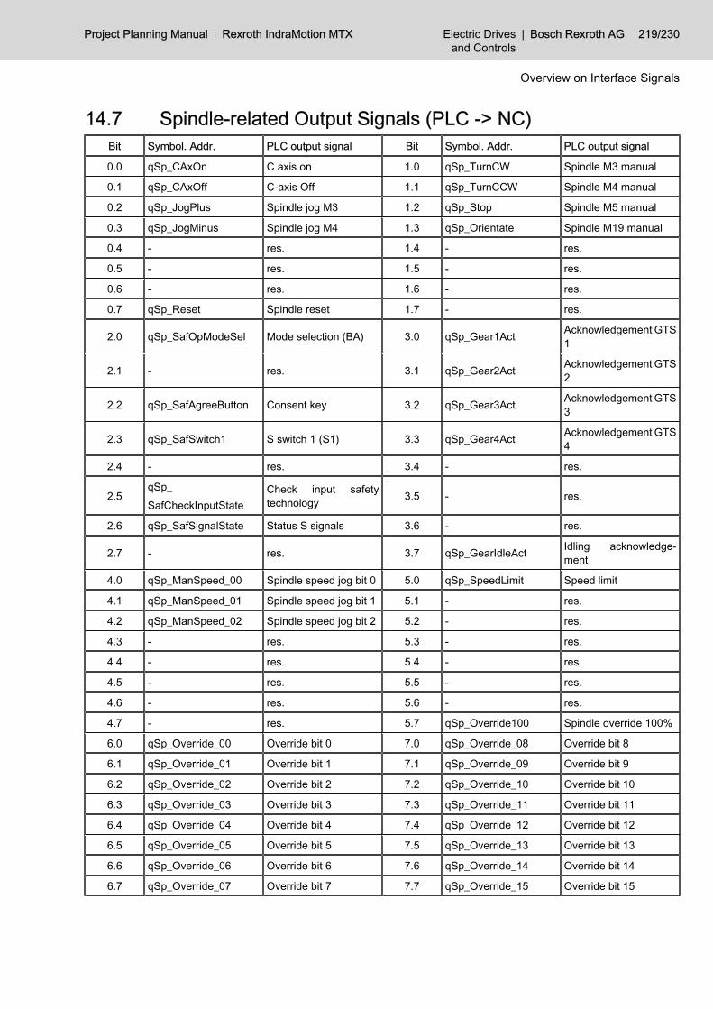
14.7 Spindle-related Output Signals (PLC -> NC)Bit Symbol. Addr. PLC output signal Bit Symbol. Addr. PLC output signal
0.0 qSp_CAxOn C axis on 1.0 qSp_TurnCW Spindle M3 manual
0.1 qSp_CAxOff C-axis Off 1.1 qSp_TurnCCW Spindle M4 manual
0.2 qSp_JogPlus Spindle jog M3 1.2 qSp_Stop Spindle M5 manual
0.3 qSp_JogMinus Spindle jog M4 1.3 qSp_Orientate Spindle M19 manual
0.4 - res. 1.4 - res.
0.5 - res. 1.5 - res.
0.6 - res. 1.6 - res.
0.7 qSp_Reset Spindle reset 1.7 - res.
2.0 qSp_SafOpModeSel Mode selection (BA) 3.0 qSp_Gear1Act Acknowledgement GTS1
2.1 - res. 3.1 qSp_Gear2Act Acknowledgement GTS2
2.2 qSp_SafAgreeButton Consent key 3.2 qSp_Gear3Act Acknowledgement GTS3
2.3 qSp_SafSwitch1 S switch 1 (S1) 3.3 qSp_Gear4Act Acknowledgement GTS4
2.4 - res. 3.4 - res.
2.5qSp_SafCheckInputState
Check input safetytechnology 3.5 - res.
2.6 qSp_SafSignalState Status S signals 3.6 - res.
2.7 - res. 3.7 qSp_GearIdleAct Idling acknowledge‐ment
4.0 qSp_ManSpeed_00 Spindle speed jog bit 0 5.0 qSp_SpeedLimit Speed limit
4.1 qSp_ManSpeed_01 Spindle speed jog bit 1 5.1 - res.
4.2 qSp_ManSpeed_02 Spindle speed jog bit 2 5.2 - res.
4.3 - res. 5.3 - res.
4.4 - res. 5.4 - res.
4.5 - res. 5.5 - res.
4.6 - res. 5.6 - res.
4.7 - res. 5.7 qSp_Override100 Spindle override 100%
6.0 qSp_Override_00 Override bit 0 7.0 qSp_Override_08 Override bit 8
6.1 qSp_Override_01 Override bit 1 7.1 qSp_Override_09 Override bit 9
6.2 qSp_Override_02 Override bit 2 7.2 qSp_Override_10 Override bit 10
6.3 qSp_Override_03 Override bit 3 7.3 qSp_Override_11 Override bit 11
6.4 qSp_Override_04 Override bit 4 7.4 qSp_Override_12 Override bit 12
6.5 qSp_Override_05 Override bit 5 7.5 qSp_Override_13 Override bit 13
6.6 qSp_Override_06 Override bit 6 7.6 qSp_Override_14 Override bit 14
6.7 qSp_Override_07 Override bit 7 7.7 qSp_Override_15 Override bit 15
Project Planning Manual | Rexroth IndraMotion MTX Electric Drivesand Controls
| Bosch Rexroth AG 219/230
Overview on Interface Signals

Bit Symbol. Addr. PLC output signal Bit Symbol. Addr. PLC output signal
8.0 qSp_Custom1 Customer input 1 9.0 - res.
8.1 qSp_Custom2 Customer input 2 9.1 - res.
8.2 qSp_Custom3 Customer input 3 9.2 - res.
8.3 qSp_Custom4 Customer input 4 9.3 - res.
8.4 qSp_Custom5 Customer input 5 9.4 - res.
8.5 qSp_Custom6 Customer input 6 9.5 - res.
8.6 qSp_Custom7 Customer input 7 9.6 - res.
8.7 qSp_Custom8 Customer input 8 9.7 - res.
10.0 - res. 11.0 - res.
10.1 - res. 11.1 - res.
10.2 - res. 11.2 - res.
10.3 - res. 11.3 - res.
10.4 - res. 11.4 - res.
10.5 - res. 11.5 - res.
10.6 - res. 11.6 qSp_DrvOn Drive on
10.7 - res. 11.7 qSp_DrvLock Spindle lock
Fig.14-7: Overview of output signals (PLC → NC)
14.8 Spindle-related Input Signals (NC -> PLC)Bit Symbol. Addr. PLC input signal Bit Symbol. Addr. PLC input signal
0.0 iSp_CAxAct C-axis is active 1.0 iSp_ProgSpReach Speed reached
0.1 iSp_CAxSwitch C axis switching 1.1 iSp_SpLim Speed limited
0.2 iSp_TurnCmd Spindle command 1.2 iSp_Stop Spindle still
0.3 iSp_TurnDirM4 Direction of rotation M4 1.3 iSp_OrientateFinish Spindle orientatet
0.4 - res. 1.4 iSp_OrientateAct Spindle orientation ac‐tive
0.5 iSp_InPos Spindle in position 1.5 - res.
0.6 iSp_PosCtrl Position control active 1.6 - res.
0.7 iSp_Reset Spindle reset 1.7 - res.
2.0 iSp_SafOpMode_00 Bit 0 safety mode 3.0 iSp_Gear1Sel GTS 1 selection
2.1 iSp_SafOpMode_01 Bit 1 safety mode 3.1 iSp_Gear2Sel GTS 2 selection
2.2 iSp_SafOpMode_02 Bit 2 safety mode 3.2 iSp_Gear3Sel GTS 3 selection
2.3 iSp_SafOpMode_03 Safety mode bit 3 3.3 iSp_Gear4Sel GTS 4 selection
2.4 iSp_SafStatePos Safe position status 3.4 iSp_GearChange GTS change
2.5iSp_SafCtrlOutputState
Control status output 3.5 iSp_IdleSpeed Idling speed reached
2.6 - res. 3.6 - res.
2.7 - res. 3.7 iSp_GearIdleSel Idle gear selection
220/230 Bosch Rexroth AG | Electric Drivesand Controls
Rexroth IndraMotion MTX | Project Planning Manual
Overview on Interface Signals

Bit Symbol. Addr. PLC input signal Bit Symbol. Addr. PLC input signal
4.0 - res. 5.0 - res.
4.1 - res. 5.1 - res.
4.2 - res. 5.2 - res.
4.3 - res. 5.3 - res.
4.4 - res. 5.4 - res.
4.5 - res. 5.5 - res.
4.6 - res. 5.6 iSp_Override0 Spindle override 0 %
4.7 - res. 5.7 iSp_Override100 Spindle override 100 %
6.0 iSp_ScsState00 SCS signal status 0 7.0 iSp_ScsState08 SCS signal status 8
6.1 iSp_ScsState01 SCS signal status 1 7.1 iSp_ScsState09 SCS signal status 9
6.2 iSp_ScsState02 SCS signal status 2 7.2 iSp_ScsState10 SCS signal status 10
6.3 iSp_ScsState03 SCS signal status 3 7.3 iSp_ScsState11 SCS signal status 11
6.4 iSp_ScsState04 SCS signal status 4 7.4 iSp_ScsState12 SCS signal status 12
6.5 iSp_ScsState05 SCS signal status 5 7.5 iSp_ScsState13 SCS signal status 13
6.6 iSp_ScsState06 SCS signal status 6 7.6 iSp_ScsState14 SCS signal status 14
6.7 iSp_ScsState07 SCS signal status 7 7.7 iSp_ScsState15 SCS signal status 15
8.0 iSp_Custom1 Customer output 1 9.0 iSp_CoupleIndex_00 No. of coupling bit 0
8.1 iSp_Custom2 Customer output 2 9.1 iSp_CoupleIndex_01 No. of coupling bit 1
8.2 iSp_Custom3 Customer output 3 9.2 iSp_CoupleIndex_02 No. of coupling bit 2
8.3 iSp_Custom4 Customer output 4 9.3 - res.
8.4 iSp_Custom5 Customer output 5 9.4 - res.
8.5 iSp_Custom6 Customer output 6 9.5 - res.
8.6 iSp_Custom7 Customer output 7 9.6 - res.
8.7 iSp_Custom8 Customer output 8 9.7 - res.
10.0 iSp_Master Spindle is Master 11.0 iSp_DrvErrClass1 Error diagn. class -1
10.1 iSp_CoupleErr Coupling Error 11.1 iSp_DrvChangeClass2 Modification statusclass 2
10.2 iSp_Synchr1 Synchronous 1 11.2 iSp_DrvChangeClass3 Modification statusclass 3
10.3 iSp_Synchr2 Synchronous 2 11.3 - res.
10.4 - res. 11.4 iSp_DryRun Test mode
10.5 - res. 11.5 iSp_DrvPower Enabled for power acti‐vation
10.6 - res. 11.6 iSp_DrvReady Drive ready
10.7 - res. 11.7 iSp_DrvAct Drive under control
Fig.14-8: Overview of input signals (NC -> PLC)
Project Planning Manual | Rexroth IndraMotion MTX Electric Drivesand Controls
| Bosch Rexroth AG 221/230
Overview on Interface Signals

Bosch Rexroth AG | Electric Drivesand Controls
Rexroth IndraMotion MTX | Project Planning Manual

15 Service and Support15.1 Helpdesk
Our service helpdesk at our headquarters in Lohr, Germany, will assist you withall kinds of inquiries.Contact us:● By phone through the Service Call Entry Center,
Monday to Friday 7:00 am - 6:00 pm CET+49 (0) 9352 40 50 60
● By fax+49 (0) 9352 40 49 41
● By e-mail: [email protected]
15.2 Service HotlineOut of helpdesk hours please contact our German service department directly:+49 (0) 171 333 88 26or+49 (0) 172 660 04 06Hotline numbers for other countries can be found in the addresses of eachregion (see below).
15.3 InternetAdditional notes regarding service, maintenance and training, as well as thecurrent addresses of our sales and service offices can be found onhttp://www.boschrexroth.comOutwith Germany please contact our sales/service office in your area first.
15.4 Helpful InformationFor quick and efficient help please have the following information ready:● Detailed description of the fault and the circumstances● Information on the type plate of the affected products, especially type co‐
des and serial numbers● Your phone and fax numbers as well as your e-mail address so we can
contact you in case of questions
Project Planning Manual | Rexroth IndraMotion MTX Electric Drivesand Controls
| Bosch Rexroth AG 223/230
Service and Support

Bosch Rexroth AG | Electric Drivesand Controls
Rexroth IndraMotion MTX | Project Planning Manual

IndexSymbols(MT_TempComp 135
AAccess to digital I/Os 117Activate block skip 54Activate MSD messages 202Active operating mode 49Appropriate use
Areas of application 5Introduction 5
Appropriate UseAreas of use 5
Asynchronous subroutine 1 ... 8 44, 53Automatic resection from 42Automatic restart 41Auxiliary functions 111Axis discharged 74Axis index 83Axis in position 79Axis interface 18Axis Mode Bit 0 and 1 66Axis near end point 80AxisNo 135Axis on notch position 79Axis override 0% 82Axis override 100% 72, 82Axis-related interface signals 63
Description PLC input signals 77Description PLC output signals 66PLC input signals - overview 90, 217PLC output signals - overview 215PLC Output signals - overview 63
Axis reset 69, 79Axis running 79Axis speed reached 80Axis transformer 2 inactive 59
BBCE code 113Binary coded active channel status 54Bit 0 safety mode ... Bit 3 80, 102Bit-coded auxiliary functions 112Block skip 45
CCancel distance to go 43Cancel fixed stop 70C-axis active 100C-axis off 92C-axis on 92C-axis switching 100Chan 138Change of state class-2 107Change of state class-3 107
Change of status class-2 85Change of status class-3 85Changing data records 162Changing tool data 152Channel Interface 17Channel number bit 0 ... Bit 3 81Channel-related interface signals 35
PLC input signals 49PLC input signals - overview 37, 64, 213PLC output signals 39PLC output signals - overview 35, 212
Channel reset 52Channel status bit 0 ... 4 53channel structure 35Check input safety state 96Check input safety technology 71Communication structure 2Compensable gantry command value displacementexceeded 84Conditional jump 46CondMask 156Configuration in IndraWorks 199Configuration of machine status display 199Configuration of the local inputs 20Configuration of the PLC NC bit interface 17Consent key 70Consent key (ZT) 96Coordinate coupling 48Coordinate coupling active 58Coupling error 106coupling lag 84Coupling lag 84CPL customer output 1 ... 16 57CPL variable 178Customer input 1 - 8 47, 73, 97Customer output 1 ... 8 57, 83, 105
DDeleting data records 156Deleting tool data records 147Diagnosis Information 205Digital I/Os 117Digital inputs of the IO card 22Digital outputs of the IO card 22Direction of rotation M4 101DP_ADDR 206DP_ID 207DP_RDREC 207DP_SLOT 206DP_WRREC 208DP master interface 117DP slaves 25DPV1 services 205Drive cutoff with interlock 106Drive in operation 87, 109
Project Planning Manual | Rexroth IndraMotion MTX Electric Drivesand Controls
| Bosch Rexroth AG 225/230
Index

Drive lock 70Drive on 75, 97Drive ready 86, 108
EEdge-triggered signals 66Edit data record lists 156Editing data records 152, 162Editing tool lists 147Edit inhibit 30ElemPath 162Enabled for power activation 86, 108End block 126Error code 119Error state class-1 84, 106Extended NC block input 132
FFast retract 44Feed 100% active 59Feed hold 41Feed hold active 52Feed inhibit 76Feed stop 41Fixed stop active 80Fixed stop reached 80
GG41/141 active 58G42/142 active 58G70 active 58G95 active 59G96 active 61Gantry command value displacement active 84Gantry on master position 74Gear in idle position 104Gear range selection 103Gear switchover function 104General Interface 17Global Interface 17Global interface signals
PLC input signals 32PLC input signals - overview 211PLC Input signals - overview 29PLC output signals 30PLC output signals - overview 29, 211
GTS 1 - 4 acknowledgement 96GTS change 104
HHand wheel data 140Handwheel direction 45, 71Handwheel position 45, 71Handwheel selection bit 0 45Handwheel selection bit 0 and bit 1 71Handwheel selection bit 1 45Hardware warning 32
Hold command position 74HS input 22HS output 22
IiAx_ChIndex_00 ... 03 81iAx_CmdOffsExceed 84iAx_CmdOffsExst 84iAx_CoupleLag 84iAx_Custom1 ... 8 83iAx_DistCtrl 80iAx_DrvAct 87iAx_DrvChangeClass2 85iAx_DrvChangeClass3 85iAx_DrvErrClass1 84iAx_DrvPower 86iAx_DrvReady 86iAx_DryRun 86iAx_FxStopAct 80iAx_FxStopReached 80iAx_InPos 79iAx_MasterAxindex_00 ... 04 83iAx_NotchPos 79iAx_Override0 82iAx_Override100 82iAx_PosSwitch1 ... 8 81iAx_ProgSpReach 80iAx_RefKnown 77iAx_RefReached 78iAx_Reset 79iAx_Run 79iAx_SafCtrlOutputState 81iAx_SafOpMode_00 ... 03 80iAx_SafStatePos 81iAx_ScsState00 ... 15 82iAx_TrqExceed 83iAx_TrqLim 86iAx_TrvCmd 78iAx_TrvDirNeg 79iCh_ActFunc01 58iCh_ActFunc02 59iCh_ActFunc03 59iCh_ActFunc04 59iCh_ActFunc05 59iCh_ActFunc06 59iCh_ActFunc07 59iCh_ActFunc08 60iCh_ActFunc09 ... 13 60iCh_ActFunc18 61iCh_ASub1 ... 8 53iCh_CoordCoupleAct 58iCh_Cpl01 ... 16 57iCh_Custom1 ... 8 57iCh_DryRun 50iCh_FeedHoldAct 52iCh_G0Act 57iCh_G41G141Act 58
226/230 Bosch Rexroth AG | Electric Drivesand Controls
Rexroth IndraMotion MTX | Project Planning Manual
Index

iCh_G42G142Act 58iCh_InPosAct 57iCh_NCReady 50iCh_OpMode_00 ... 03 49iCh_Override0 57iCh_Override100 57iCh_ProgRun 51iCh_ProgStopM0 52iCh_ProgStopM30 52iCh_ReadyReEnter 53iCh_ReEnterAct 53iCh_RemoveFinish 52iCh_Reset 52iCh_RetraceAct 58iCh_SRunAct 56iCh_SRunReEnter 57iCh_SRunRepos 57iCh_State_00 .. 04 53iCh_TangTRotCmd 58iCh_TransferLockAct 51Idle gear acknowledgment 96Idle gear selection 104Idling position of the gear 104Idling speed reached 104iGen_HardwareState 32iGen_NoStroke 33iGen_StrokeIntend 33Importing device master files 24Importing GSD files 24Inappropriate use, 6
Consequences, disclaimer of liability 5Inch increments 68Incremental step as diameter 69Incremental step in inch 68Incremental steps in diameter 69Index of master axis bit 0 ... Bit 4 83Inpos range 2 active 57Input of a parameter value 143Input signals (NC → PLC) 32IReduce transfer time 77, 99iSp_CAxAct 100iSp_CAxSwitch 100iSp_CoupleErr 106iSp_CoupleIndex_00 ... 02 105iSP_Custom1 ... 8 105iSp_DrvAct 109iSp_DrvChangeClass2 107iSp_DrvChangeClass3 107iSp_DrvErrClass1 106iSp_DrvPower 108iSp_DrvReady 108iSp_DryRun 108iSp_Gear1Sel ... 4Sel 103iSp_GearChange 104iSp_GearIdleSel 104iSp_IdleSpeed 104iSp_InPos 101iSp_Master 105
iSp_OrientateAct 102iSp_OrientateFinish 102iSp_Override0 104iSp_Override100 104iSp_PosCtrl 101iSp_ProgSpReach 101iSp_Reset 101iSp_SafCtrlOutputState 103iSp_SafOpMode_00 ... 03 102iSp_SafStatePos 103iSp_ScsState00 ... 15 105iSp_SpLim 102iSp_Stop 102iSp_Synchr1 106iSp_Synchr2 106iSp_TurnCmd 100iSp_TurnDirM4 101
LLent axis 82Limit switch range 0 ... 1 69Load database table 171
MMachine status display 199Manual- 67Manual+ 67Manual feed for bit 0 ... Bit 3 72M keys 21Mode selection 70Mode selection (BA) 96MSD 199MSD bit interface 199MSD file 201MSD text 201MT_CfgData 137MT_CplData 178MT_CplDataConv 181MT_DbData 162MT_DbLoad 171MT_DbRecList 156MT_DbSave 168MT_DiagCode 189MT_DiagText 193MT_Handw 140MT_NcBlk 128MT_NcBlkExt 132MT_P_DbData 152MT_P_DbRecList 147MT_ProgSel 124MT_ScsData 143MT_ScsPos 119MT_SD_RD 183MT_SD_WR 186MT_TCorr 174
Project Planning Manual | Rexroth IndraMotion MTX Electric Drivesand Controls
| Bosch Rexroth AG 227/230
Index

NNC block input 128NC program restart active 56NC ready 50NC start 41Negative traversing direction 79Next notch position 69NmbOfValues 135No. of coupling bit 0 ... Bit 2 105NofElem 156Non-bit-coded channel-dependent auxiliary func‐tions 114Non-bit-coded channel-independent auxiliary func‐tions 113
OOnline correction direction 47Online correction enable 47Operating status messages 107Optional stop 46, 55Orientate spindle active 102Original channel 82Output signals (PLC → NC ) 30Override 0% 57Override 100% 46, 57Override bit 0 ... Bit 15 47, 73, 97
PParameterization of machine status indication 199PLC input signals, 49
Axis-related interface signals 77Global interface signals 32
PLC input signals (NC -> PLC) 100PLC operating mode 40PLC output signals, 39, 92
Axis-related interface signals 66Global interface signals 30
Position control active 101Position switch point 1 - 8 81Profibus configuration 23, 25PROFIBUS-DP
I/O configuration 117PROFIBUS-DP interface 117Profibus master 23Program change 125Program end M30 52Program modules 119Program modules - General structure 119ProgramName 126Program position active 59Program running 51Program selection/deselection 124Program stop M0 52Punching HS logic 31
QqAx_Custom1 ... 8 73
qAx_Discharge 74qAx_DrvLock 76qAx_DrvOn 75qAx_FrzIpoPos 74qAx_FxStopRel 70qAx_HandwDir 71qAx_HandwPosMode 71qAx_HandwSel_00 ... 01 71qAx_JogDia 69qAx_JogInch 68qAx_JogMinus 67qAx_JogPlus 67qAx_LagErrOff 73qAx_ManFeed_00 ... 03 72qAx_MasterPos 74qAx_NextNotch 69qAx_OpModeSel_00 ... 01 66qAx_Override_00 ... 15 73qAx_Override100 72qAx_Reset 69qAx_SafCheckInputState 71qAx_SafDrvLock 70qAx_SafEnablCtrl 70qAx_SafOpModeSwitch 70qAx_SafRedTransTime 77qAx_SafSwitch1 70qAx_SafTechState 71qAx_SwLimOff 70qAx_TakeActOffs 74qAx_TrqErrOff 73qAx_TrqLim 75qAx_TrvLim_00 ... 01 69qCh_ASub1 ... 8 44qCh_BlkSlash 45, 54qCh_CancDist 43qCh_CoordCoupleOff 48qCh_CtrlReset 42qCh_Custom1 ... 8 47qCh_FeedHold 41qCh_FeedStop 41qCh_HandwDirWcs 45qCh_HandwPosMode 45qCh_HandwSelWcs_00 45qCh_HandwSelWcs_01 45qCh_JogMinusWcs 45qCh_JogPlusWcs 45qCh_NCStart 41qCh_NextBlk 43qCh_OnlCorrWcs 47qCh_OnlCorrWcsDir 47qCh_OpModePlc 40qCh_OpModeSel_00 ... 03 39qCh_OptJump 46qCh_OptStop 46, 55qCh_Override_00 ... 15 47qCh_Override100 46qCh_RedRap 46qCh_ReSelOff 42
228/230 Bosch Rexroth AG | Electric Drivesand Controls
Rexroth IndraMotion MTX | Project Planning Manual
Index

qCh_Restart 41qCh_RetCont 44qCh_Retrace 47qCh_RetraceMovFwd 48qCh_RetraceMovRev 48qCh_Retract 44qCh_TangTRotRel 48qCh_TestFeed 48qCh_TestRap 49qCh_TransferLock 41qGen_DelErrInfo 32qGen_EditInhibit 30qGen_Reset 30qGen_StrokeInhibit 31qGen_StrokeRel 31qGen_StrokeReserv 31qSp_CAxOff 92qSp_CAxOn 92qSp_Custom1 ... 8 97qSp_DrvLock 98qSp_DrvOn 97qSp_Gear1Act ... 4Act 96qSp_GearIdleAct 96qSp_JogMinus 92qSp_JogPlus 92qSp_ManSpeed_00 ... 02 97qSp_Orientate 95qSp_Override_00 ... 15 97qSp_Override100 97qSp_Reset 93qSp_SafAgreeButton 96qSp_SafCheckInputState 96qSp_SafModeSel 96qSp_SafRedTransTime 99qSp_SafSignalState 96qSp_SafSwitch1 96qSp_Stop 94qSp_SValueSD 100qSp_TurnCCW 94qSp_TurnCW 94
RRandom addressing 26Rapid traverse 57Rapid traverse G0 46Read/write of perm. CPL variables 178Read/write of perm. CPL variables with type conver‐sion 181Read diagnostics data (MT_DiagCode) 189Read diagnostics data (MT_DiagText) 193Reading actual axis values 119Reading a parameter value 143Reading machine parameter 137Reading of data records 162Reading tool data 152Read system data 183Ready to re-enter contour 53
Reduced rapid traverse 46Re-entry active 53, 57Reference point known 77Reference point was reached 78Remove finish 52Repositioning active 57Reset 42Return to contour 44RIL_ProfibusDP 205
SSafe absolute position 81Safety instructions for electric drives 7Save database table 168SCS signal status 0 ...15 82, 105SD qSp_SpeedLimit 99Searching for data records 156Searching for tool data records 147Selection GTS 1 ... 4 103Selection of operating mode 39Selection of the DP master 205SelMask 168, 171SERCOS parameters 143Series of addresses without gaps 26SetPos offset 59Setting addresses in a DP slave 26Setting correction values 174Speed limitation 99Speed limited 102Speed reached 101Spindle anticlockwise rotation 94Spindle clockwise rotation 94Spindle has stopped 102Spindle inhibit 98Spindle in position 101Spindle Interface 19Spindle is master 105Spindle jog M3 92Spindle jog M4 92Spindle M19 manual 95Spindle M3 manual 94Spindle M4 manual 94Spindle M5 manual 94Spindle orientated 102Spindle orientation 95Spindle override 0% 104Spindle override 100% 97, 104Spindle-related interface signals
Description PLC output signals 92Input signals (NC -> PLC) 100Output signals PLC -> NC 92PLC input signals - overview 220PLC output signals - overview 89, 219
Spindle reset 93, 101Spindle speed jog bit 0 ... Bit 2 97Spindle stop 94S switch 1 (S1) 70, 96
Project Planning Manual | Rexroth IndraMotion MTX Electric Drivesand Controls
| Bosch Rexroth AG 229/230
Index
Standstill error 83Start block 126State output controller 103State S signals 96Static signals 66Status output controller 81Status safe position 81, 103Status S signals 71Stroke inhibit 31Stroke intended 33Stroke is not running 33Stroke on 31Stroke reserve 31Suppress coupling error 73Suppress limit switches 70Suppress standstill error 73S value specification via SD 100Switching to next block 43Switch off prewarning 107Synchronous 1 106Synchronous 2 106System reset 30
TTake over actual value offset 74TangTool 58Tapping active 59, 60Temperature compensation 135Terminate coupling 48Test feed 48Test mode 50, 86, 108
Test rapid traverse 49Thread cycle active 59ThreadSet 59Tool compensation active bit 0 ... Bit 4 60Tool correction 174Tool rotation (TangTool (TTL)) 58Torque reduced 86Torque reduction 75Transfer lock 41Transfer lock active 51Travel command 78TTL enable 48Turn command 100TypeId 162
UUser level - Edit inhibit 30UTF8 character coding 202
VVersion_RIL_ProfibusDP_01V01 206
WWCS manual - 45WCS manual + 45Write system data 186
XXPath 183, 186
230/230 Bosch Rexroth AG | Electric Drivesand Controls
Rexroth IndraMotion MTX | Project Planning Manual
Index

Notes
Project Planning Manual | Rexroth IndraMotion MTX Electric Drivesand Controls
| Bosch Rexroth AG

Bosch Rexroth AGElectric Drives and ControlsP.O. Box 13 5797803 Lohr, GermanyBgm.-Dr.-Nebel-Str. 297816 Lohr, GermanyPhone +49 (0)93 52-40-50 60Fax +49 (0)93 52-40-49 [email protected]
Printed in GermanyDOK-MTX***-PLC*INT*V08-PR01-EN-PR911322275