58-page presentation
TRANSCRIPT
Presentation to
McHenry County CollegeCrystal Lake, IL
FM/TV Broadcast Facilityto include
1-1500 ft Self Supporting Tower
B M B C O M M U N I C A T I O N S M A N A G E M E N T , L L C
F e b r u a r y 1 8 , 2 0 0 9

Introduction
‣BMB Communications Management,LLC was formed in 2003 as an Oklahoma Limited Liability Company. It is owned by 3 partners, John Maguire, Jason Bradshaw and Ronald Bradshaw.
‣BMB has constructed, owned, operated and managed over 30 towers in the United States.
‣BMB’s clients have included broadcast companies such as College Creek Media LLC, Aurora Media LLC, M&M Broadcasting LLC, Sky Media LLC, Portland Broadcasting LLC and Resurgence Media LLC.

Economic Benefits
The construction of the site alone will greatly benefit the local economy. BMB will use local vendors when possible for some of the following construction work.
‣Concrete
‣Electrical
‣Excavation and Fencing
‣Miscellaneous Civil Work

Alan D. KirshnerEngineering experience
37 Years Broadcast Engineering Experience
FCC First Class Radiotelephone Operators License held since 1973
Past Projects:
Design and installation-former World Trade Center
Design and installation-Empire State Building
Design and installation-Stratosphere (Las Vegas, NV)
Licenses Held
FCC General Class Radio Telephone License with Ship Radar Endorsement FCC Amateur Radio Operator License FAA Private Pilot Certificate (own plane) New York State Private Trade School Teachers Certificate
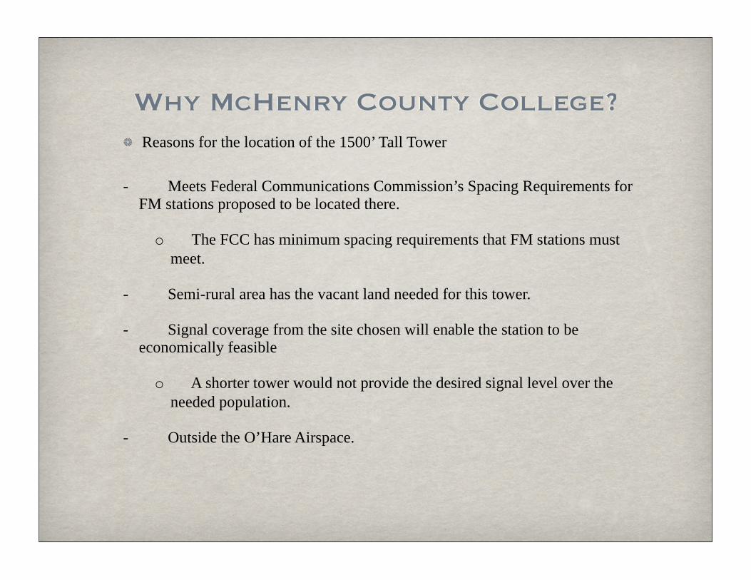
Why McHenry County College?Reasons for the location of the 1500’ Tall Tower
- Meets Federal Communications Commission’s Spacing Requirements for FM stations proposed to be located there.
o The FCC has minimum spacing requirements that FM stations must meet.
- Semi-rural area has the vacant land needed for this tower.
- Signal coverage from the site chosen will enable the station to be economically feasible
o A shorter tower would not provide the desired signal level over the needed population.
- Outside the O’Hare Airspace.

Improved Coverage
• Improved Coverage for Stations Will Result In:
– Better coverage for populated areas North and West of Chicago– Additional choices for listeners in high growth areas– A chance for small business owners to have an outlet for
advertising– Additional local communities receiving first aural services
• Resulting in better news and public service coverage of these communities
– Most Importantly, better EMERGENCY SERVICES COVERAGE of West Metro Communities that are not now being served• Severe Weather Alerts
–Tornado Warnings–Flood Warnings–Lightning Storm Warnings–Blizzard Warnings
• Hazardous Material Spills• Amber Alerts

Coverage From Proposed Location
Radiofrequency Electromagnetic Exposure

FCC FM Model for Calculating Radio Frequency

FCC FM Model for Calculating Radio Frequency Electromagnetic Exposure Levels
• The FCC Program shows that a maximum Power Density of 0.2502 µW/cm² at a distance of 1,746 meters or 5,726.9 feet from the base of the tower.
• The study was performed using an Electronics Research, Incorporated SHPX-4AC-HW antenna designed with 4 radiating bays spaced ½ wavelength apart. This antenna was chosen for, among other things, its very low downward radiation characteristics in the immediate vicinity of the tower.
• This graph shows that there will be virtually no radiation at the base of the tower and negligible radiation even at the maximum value shown.

Electronics Research, Inc. SHPX-4AC-HW Antenna Specifications
• Left picture shows the mechanical specifications of the SHPX-4AC-HW antenna proposed.• Right picture shows the Vertical Plane Plot (downward radiation) characteristics of the SHPX-4AC-
HW antenna– The vertical axis depicts the relative field voltage.
• As can be seen, the relative field approaches 0 at the base of the tower.– The horizontal axis shows the number of degrees below the horizontal plane of the antenna.
FCC OET Bulletin 56Questions and Answers about Biological Effects and Potential Hazards of
Radiofrequency Electromagnetic FieldsAugust 1999
• The following slide contains information take from the FCC’s OET Bulletin 56

FCC OET Bulletin 56Questions and Answers about Biological Effects and
Potential Hazards of Radio-frequency Electromagnetic Fields
• The previous graphs calculated using the FCC’s FM Model Program showed a maximum Power Density of 0.2502 µW/cm²
• The information supplied in Table 1 (A) of the FCC’s OET Bulletin 56 shows the limit for Occupational/Controlled to be 1 mW/cm² (1000 µW/cm²)
– Therefore the maximum Power Density of this antenna will represent only 0.025% of the maximum allowed for Workers in the vicinity of the tower.
• The information supplied in Table 1 (B) of the FCC’s OET Bulletin 56 shows the limit for General Public/Uncontrolled to be 0.2 mW/cm² (200 µW/cm²)
– Therefore, the maximum Power Density for this antenna will represent only 0.125% of the maximum allowed for the General Public
• To protect workers in the vicinity of the tower or antenna where the Power Density exceeds the maximum values allowed (over 100%), the FCC adds the following language to all AM, FM and TV Licenses (A copy of a typical FCC license is in the next slide)
– The permittee/licensee in coordination with other users of the site must reduce power or cease operation as necessary to protect persons having access to the site, tower or antenna from radiofrequency electromagnetic fields in excess of FCC guidelines.

Typical FCC License for Multi-User Antenna SiteNote Special Operating Condition 1
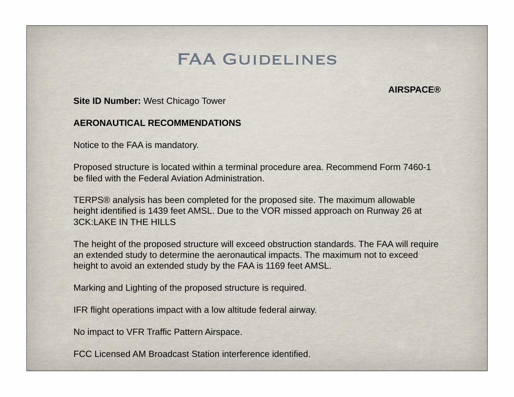
FAA GuidelinesAIRSPACE®
Site ID Number: West Chicago Tower
AERONAUTICAL RECOMMENDATIONS
Notice to the FAA is mandatory.
Proposed structure is located within a terminal procedure area. Recommend Form 7460-1 be filed with the Federal Aviation Administration.
TERPS® analysis has been completed for the proposed site. The maximum allowable height identified is 1439 feet AMSL. Due to the VOR missed approach on Runway 26 at 3CK:LAKE IN THE HILLS
The height of the proposed structure will exceed obstruction standards. The FAA will require an extended study to determine the aeronautical impacts. The maximum not to exceed height to avoid an extended study by the FAA is 1169 feet AMSL.
Marking and Lighting of the proposed structure is required.
IFR flight operations impact with a low altitude federal airway.
No impact to VFR Traffic Pattern Airspace.
FCC Licensed AM Broadcast Station interference identified.

Government Approvals and Permits
‣The Federal Aviation Administration
‣The Federal Communication Administration
‣NEPA (National Environmental Policy Act)
‣Local zoning
‣Federal, state and local permitting

Cabin Canyon, NVCabin Canyon, NV: This tower was built on Bureau of Land Management Land near Mesquite, NV. It is 190’ and was built for four FM broadcast stations.

Senator MT.Senator Mt, AZ: This tower was built for two FM broadcast stations at close to a 4,000’ elevation. The tower is 199’ high, with a 12’ X 20’ transmitter building. BMB constructed over 7 miles of new mountain road to access the site.

Portland TowerPortland, OR: This tower is a 550 ft Self Supporting tower built on State of Oregon
Forestry Land. It has a 20’x20’ transmitter building and sits on a 100’x 80’ compound.

Safety and Construction
Mr. Ernie Jones, VP of Engineering - Structural Division, Electronic Research, Inc.
Designs and fabricates steel structures such as the 1500 ft tower we are discussing.
PE (Professional Engineers) Licenses held 19 states.
36 years of experience.
Tall Tower Presentation for
Ernest R. Jones, P.E.VP Engineering ERI
2-18-2009

Self Supporting Towers

Typical Guyed Towers
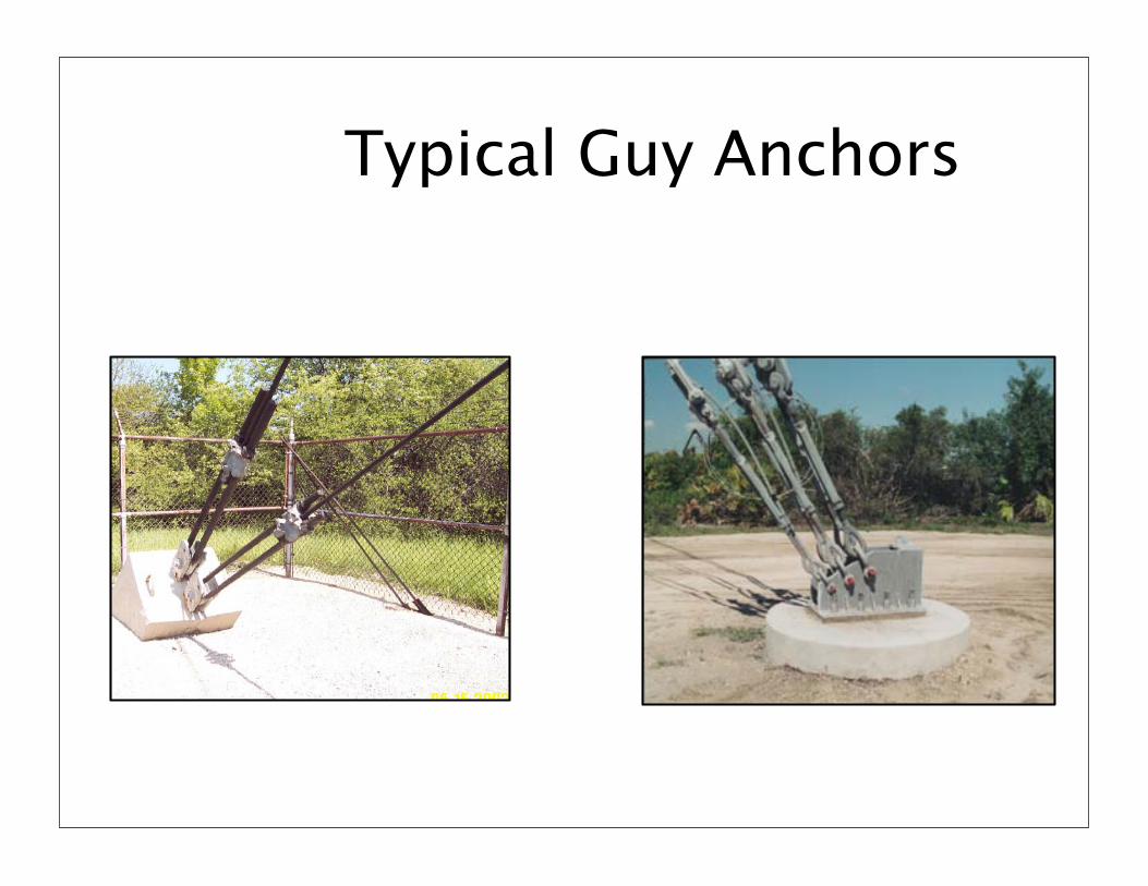
Typical Guy Anchors
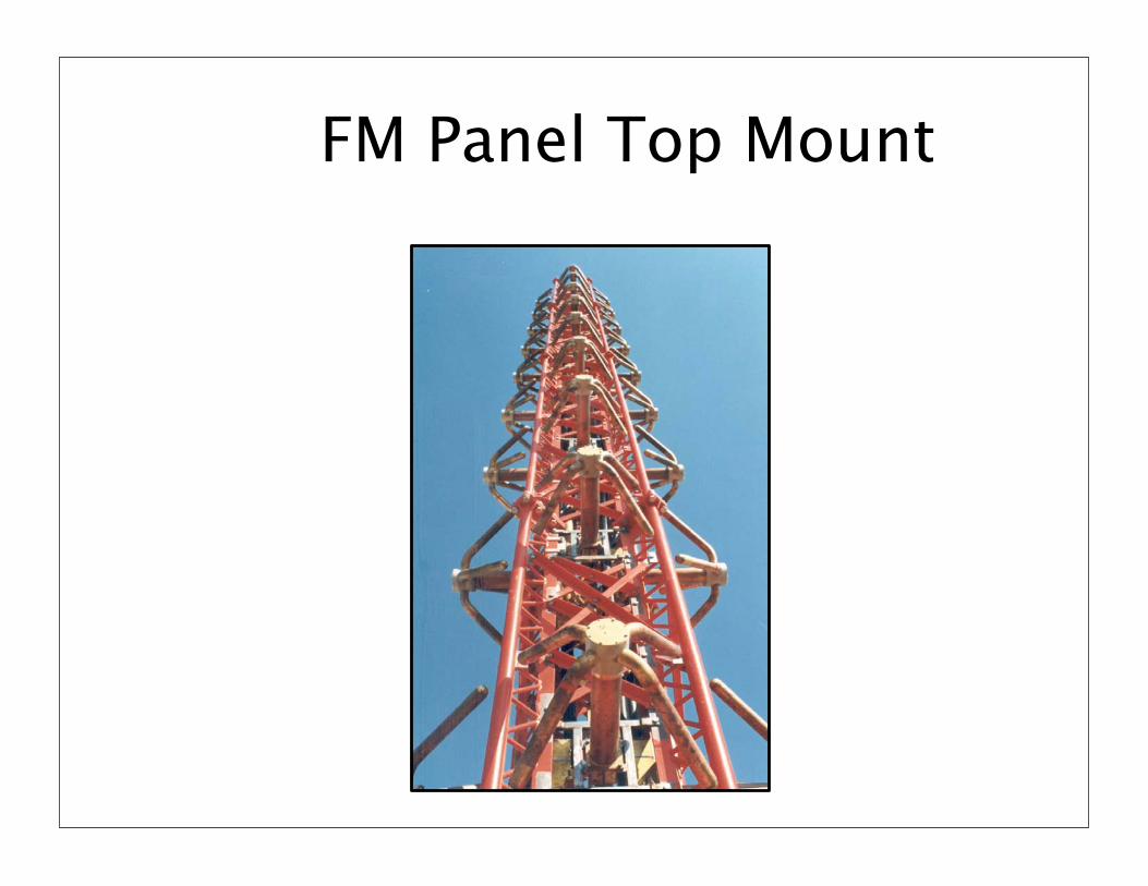
FM Panel Top Mount
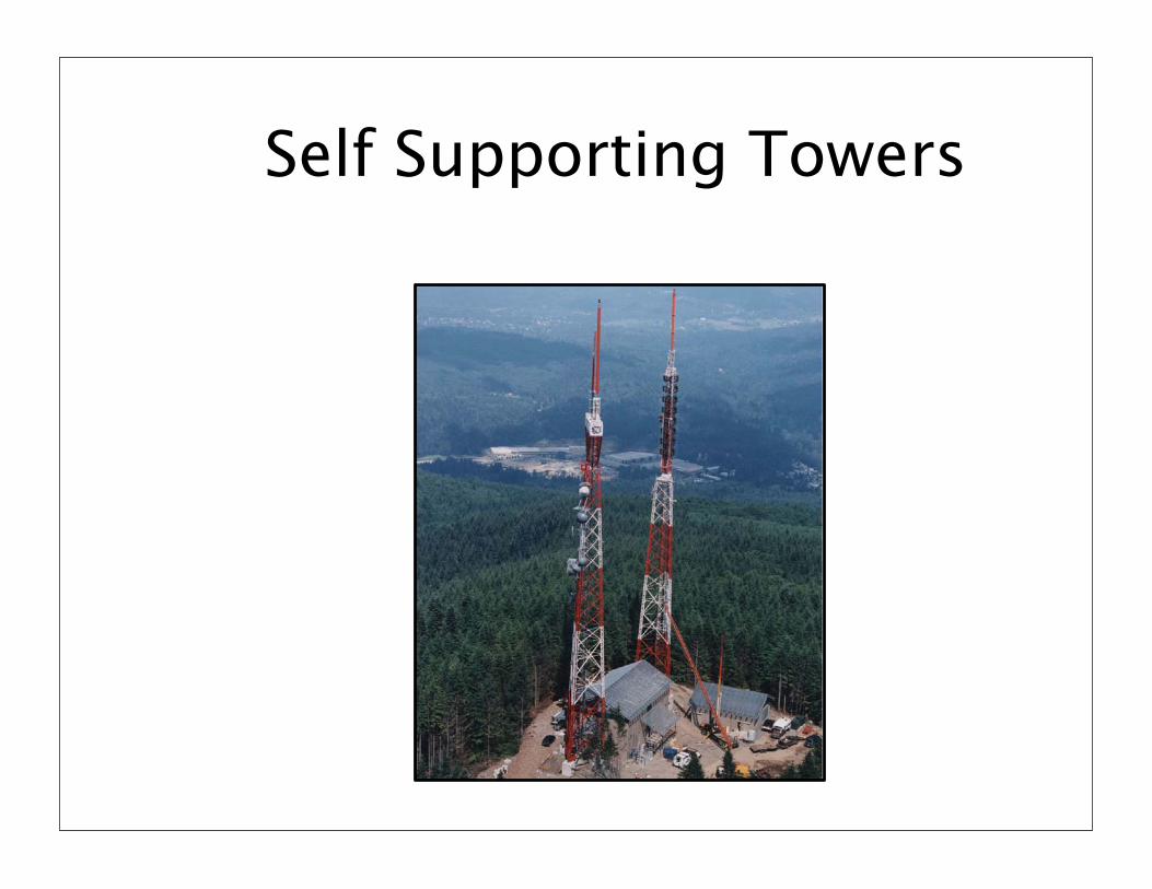
Self Supporting Towers

Self Supporting Towers

Self Supporting Towers
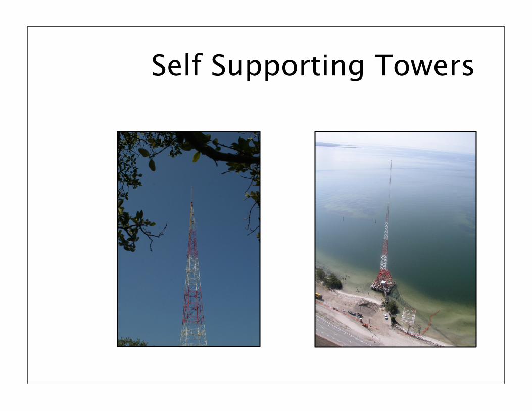
Self Supporting Towers

Built-Up Tower Leg
Built-up Leg

Tower on Empire State Building New York
Tower on Top of Empire State Building
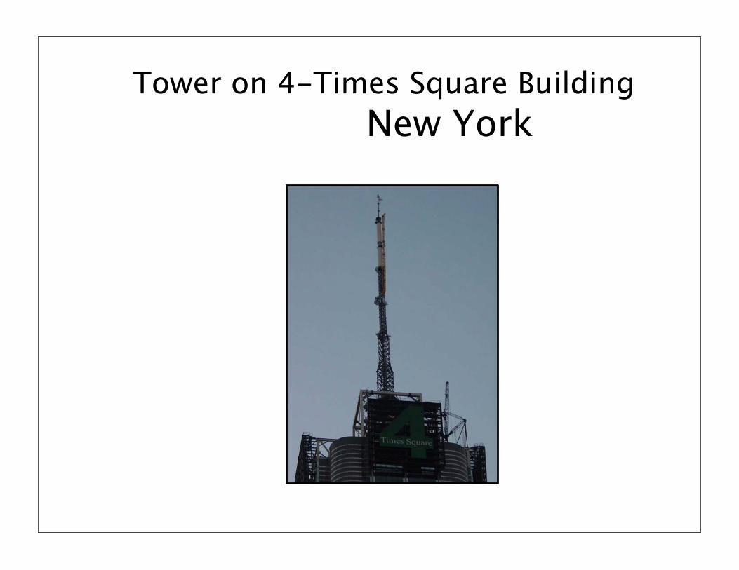
Tower on 4-Times Square Building New York

Towers on John Hancock Building Chicago

Eiffel Tower

Various Tall Structures


Tower Design with over a dozen load cases each with 12 wind directionsaround the structure.
Wind Criteria - 90 mph at Ground Increasing to 118 mph above 900’
Wind With Ice – 40 mph with ¾” ice 40 mph at Ground – 52 mph at Top 1.5” ice at Ground – 2.5” ice at top
TIA-222-G

Tower Plot:
136’ Center to Center on Tower Legs
Plot Size Approximately 200’ x200’

Proto-Type Tower Foundation
Estimated 1,600 Cu. Yds. of Concrete
184’ x 172’ Outer Dimensions of Foundation

Falling Ice


• There is very little information about the area at a site
which can be hit by shedding ice.
• It depends strongly on the structure and form of the ice in question and the actual wind speeds occurring during shedding events.
• The actual wind direction decides the direction of falling ice. When a piece of ice is released from a structure, gravity and wind drag determine its trajectory.
• Exact trajectories are difficult to predict because ice pieces are of different sizes, densities and shapes.
• The higher the wind speeds and the smaller the ice shape dimension the longer is the distance between the structure and the impact location of ice on the ground.

ICE ZONE AREAS
Red Zone – 150’ From Center of Tower
Orange Zone – 150’ to 300’ From Center of Tower
Green Zone – 300’ to 600’ From Center of Tower
Blue Zone – 600’ to 1000’ From Center of Tower

Red Zone – 150’ From Center of Tower • This Zone is Potential High Impact Zone if Winds are Moderate• Should be Marked off if Detrimental Icing Occurs• Roofs and Walkways Should have Ice Protection• Autos Should Not Park in this Area
Orange Zone – 150’ to 300’ From Center of Tower This Zone Should be Considered a Moderate Impact Zone A Warning for this Area is Recommended, Especially in the Event of High Winds or Gusty Winds. A Program Based on Site Experience of Alerting Personnel of Ice Hazards and Appropriate Protection Should be Implemented.
Green Zone – 300’ to 600’ From Center of Tower In This Zone Expect - Large Pieces of Ice Travelling Out is Not Expected. Ice that is Lighter and in More of a Sheet Form is the Most Expected in this Area During Gusty Wind Conditions.
Blue Zone – 600’ to 1000’ From Center of Tower In this Area we Expect Lighter Pieces of Ice Similar to Hail Conditions, if Winds are High and/or Gusty.

Tower Fall Radius
• Unless a special design is implemented it is possible for a Self Supporting Tower to fall in a near layout condition!

Self Supporting Tower Catastrophic Layout Type Failure

Folding of Tower Mast

Design with “First to Yield Section Concept”

First To Yield Sections
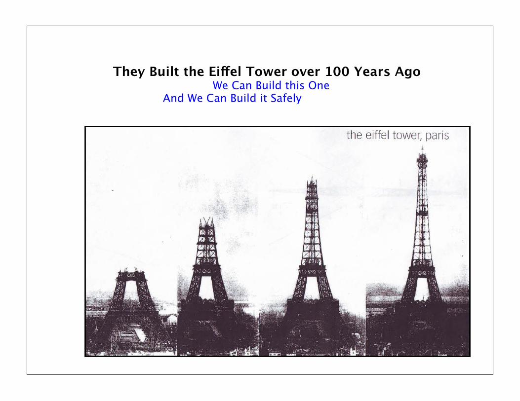
They Built the Eiffel Tower over 100 Years Ago We Can Build this One And We Can Build it Safely

Tower Industry Construction Standard
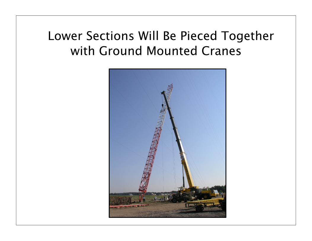
Lower Sections Will Be Pieced Together with Ground Mounted Cranes
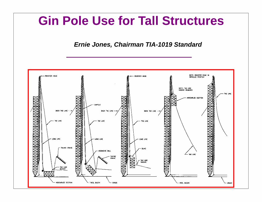
Gin Pole Use for Tall Structures
Ernie Jones, Chairman TIA-1019 Standard

Tilted Gin Pole Inside Tower
Gin Pole Inside Tower

Gin Pole Positioned Outside of Tower
Gin Pole
Tower
Section Being Lifted

Sequence of Turning a Lifted Load With Gin Pole

Questions?
Ernie Jones. P.E.Electronics Research7777 Gardner RoadChandler, IN 47610Ph: (812) [email protected]