57-9015-1 carb - kandn.com
TRANSCRIPT
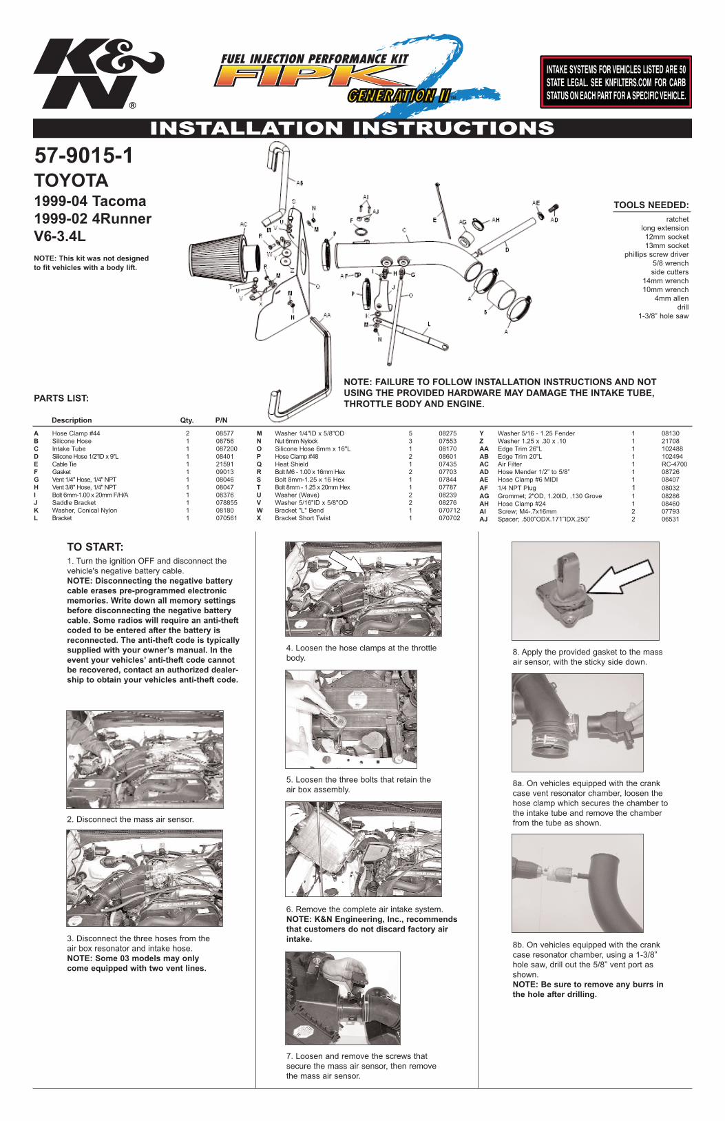
57-9015-1
TOOLS NEEDED:
PARTS LIST:
TO START:
ratchetlong extension12mm socket13mm socket
phillips screw driver5/8 wrenchside cutters
14mm wrench10mm wrench
4mm allendrill
1-3/8” hole saw
1. Turn the ignition OFF and disconnect thevehicle's negative battery cable.NOTE: Disconnecting the negative batterycable erases pre-programmed electronicmemories. Write down all memory settingsbefore disconnecting the negative batterycable. Some radios will require an anti-theftcoded to be entered after the battery isreconnected. The anti-theft code is typicallysupplied with your owner’s manual. In theevent your vehicles’ anti-theft code cannotbe recovered, contact an authorized dealer-ship to obtain your vehicles anti-theft code.
2. Disconnect the mass air sensor.
4. Loosen the hose clamps at the throttlebody.
5. Loosen the three bolts that retain theair box assembly.
6. Remove the complete air intake system.NOTE: K&N Engineering, Inc., recommendsthat customers do not discard factory airintake.
7. Loosen and remove the screws thatsecure the mass air sensor, then removethe mass air sensor.
3. Disconnect the three hoses from theair box resonator and intake hose.NOTE: Some 03 models may onlycome equipped with two vent lines.
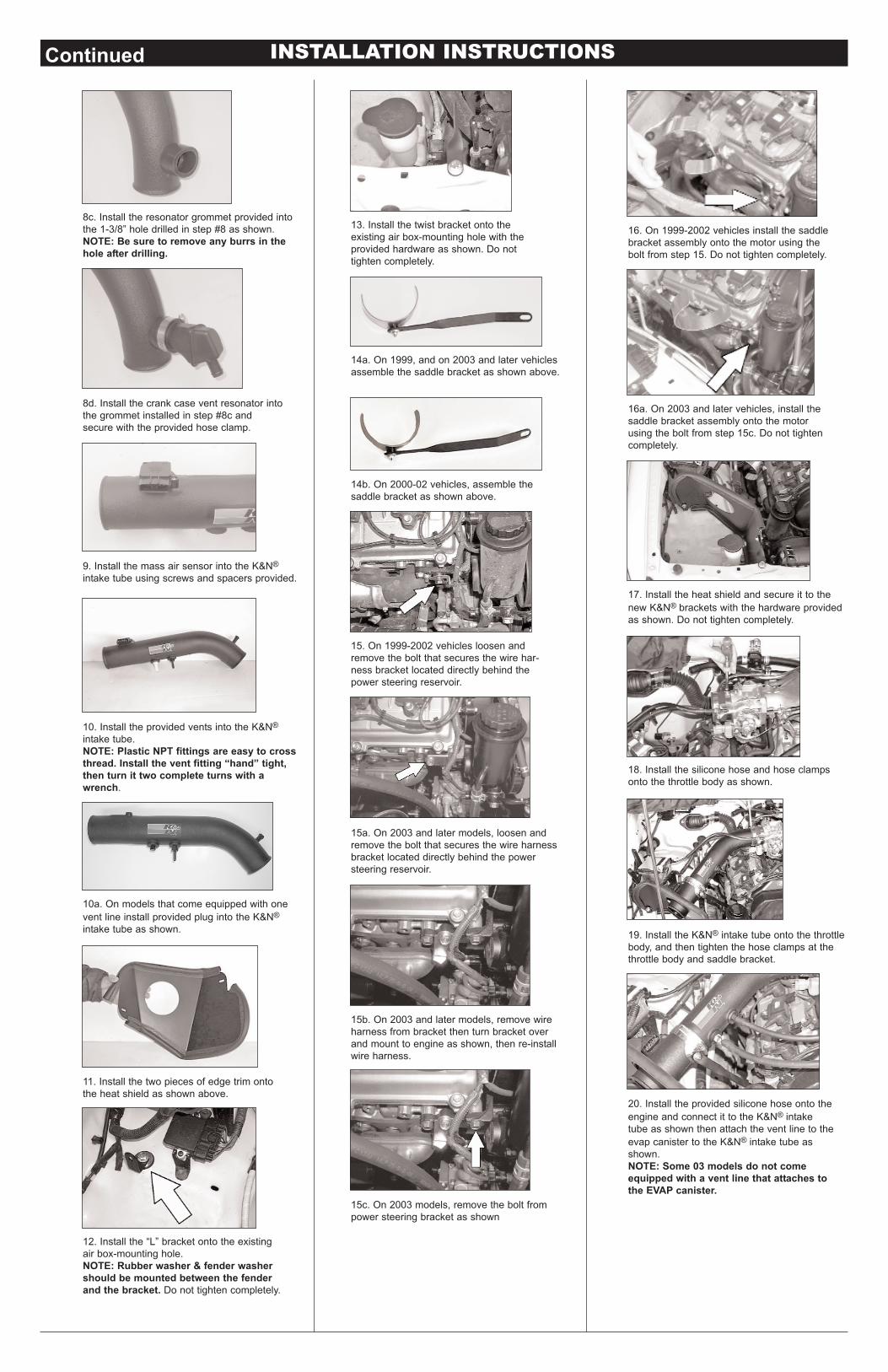
8. Apply the provided gasket to the massair sensor, with the sticky side down.
A Hose Clamp #44 2 08577B Silicone Hose 1 08756C Intake Tube 1 087200D Silicone Hose 1/2"ID x 9"L 1 08401E Cable Tie 1 21591F Gasket 1 09013G Vent 1/4" Hose, 1/4" NPT 1 08046H Vent 3/8" Hose, 1/4" NPT 1 08047I Bolt 6mm-1.00 x 20mmF/H/A 1 08376J Saddle Bracket 1 078855K Washer, Conical Nylon 1 08180L Bracket 1 070561
M Washer 1/4"ID x 5/8"OD 5 08275N Nut 6mmNylock 3 07553O Silicone Hose 6mm x 16"L 1 08170P Hose Clamp #48 2 08601Q Heat Shield 1 07435R Bolt M6 - 1.00 x 16mmHex 2 07703S Bolt 8mm-1.25 x 16 Hex 1 07844T Bolt 8mm - 1.25 x 20mmHex 1 07787U Washer (Wave) 2 08239V Washer 5/16"ID x 5/8"OD 2 08276W Bracket "L" Bend 1 070712X Bracket Short Twist 1 070702
Y Washer 5/16 - 1.25 Fender 1 08130Z Washer 1.25 x .30 x .10 1 21708AA Edge Trim 26"L 1 102488AB Edge Trim 20"L 1 102494AC Air Filter 1 RC-4700AD Hose Mender 1/2” to 5/8” 1 08726AE Hose Clamp #6 MIDI 1 08407AF 1/4 NPT Plug 1 08032AG Grommet; 2"OD, 1.20ID, .130 Grove 1 08286AH Hose Clamp #24 1 08460AI Screw; M4-.7x16mm 2 07793AJ Spacer; .500”ODX.171”IDX.250” 2 06531
TOYOTA1999-04 Tacoma1999-02 4RunnerV6-3.4L
Description Qty. P/N
8a. On vehicles equipped with the crankcase vent resonator chamber, loosen thehose clamp which secures the chamber tothe intake tube and remove the chamberfrom the tube as shown.
8b. On vehicles equipped with the crankcase resonator chamber, using a 1-3/8”hole saw, drill out the 5/8” vent port asshown.NOTE: Be sure to remove any burrs inthe hole after drilling.
NOTE: FAILURE TO FOLLOW INSTALLATION INSTRUCTIONS AND NOTUSING THE PROVIDED HARDWARE MAY DAMAGE THE INTAKE TUBE,THROTTLE BODY AND ENGINE.
NOTE: This kit was not designedto fit vehicles with a body lift.
INSTALLATION INSTRUCTIONS
20. Install the provided silicone hose onto theengine and connect it to the K&N® intaketube as shown then attach the vent line to theevap canister to the K&N® intake tube asshown.NOTE: Some 03 models do not comeequipped with a vent line that attaches tothe EVAP canister.
19. Install the K&N® intake tube onto the throttlebody, and then tighten the hose clamps at thethrottle body and saddle bracket.
Continued
15. On 1999-2002 vehicles loosen andremove the bolt that secures the wire har-ness bracket located directly behind thepower steering reservoir.
15a. On 2003 and later models, loosen andremove the bolt that secures the wire harnessbracket located directly behind the powersteering reservoir.
15b. On 2003 and later models, remove wireharness from bracket then turn bracket overand mount to engine as shown, then re-installwire harness.
15c. On 2003 models, remove the bolt frompower steering bracket as shown
16. On 1999-2002 vehicles install the saddlebracket assembly onto the motor using thebolt from step 15. Do not tighten completely.
14a. On 1999, and on 2003 and later vehiclesassemble the saddle bracket as shown above.
14b. On 2000-02 vehicles, assemble thesaddle bracket as shown above.
17. Install the heat shield and secure it to thenew K&N® brackets with the hardware providedas shown. Do not tighten completely.
18. Install the silicone hose and hose clampsonto the throttle body as shown.
16a. On 2003 and later vehicles, install thesaddle bracket assembly onto the motorusing the bolt from step 15c. Do not tightencompletely.
13. Install the twist bracket onto theexisting air box-mounting hole with theprovided hardware as shown. Do nottighten completely.
10. Install the provided vents into the K&N®intake tube.NOTE: Plastic NPT fittings are easy to crossthread. Install the vent fitting “hand” tight,then turn it two complete turns with awrench.
10a. On models that come equipped with onevent line install provided plug into the K&N®intake tube as shown.
11. Install the two pieces of edge trim ontothe heat shield as shown above.
12. Install the “L” bracket onto the existingair box-mounting hole.NOTE: Rubber washer & fender washershould be mounted between the fenderand the bracket. Do not tighten completely.
9. Install the mass air sensor into the K&N®intake tube using screws and spacers provided.
8c. Install the resonator grommet provided intothe 1-3/8” hole drilled in step #8 as shown.NOTE: Be sure to remove any burrs in thehole after drilling.
8d. Install the crank case vent resonator intothe grommet installed in step #8c andsecure with the provided hose clamp.
• 1455 CITRUS ST., P.O. BOX 1329, RIVERSIDE, CA., U.S.A. 92502 • TECH SERVICE 800-858-3333 • FAX 951-826-4001• e-mail: [email protected]® • WWW: http://www.knfilters.com®
* FREE K&N® decal To register your warranty, please see us online at knfilters.com/register. FREE K&N® decal *
INSTALLATION INSTRUCTIONSContinued
22. Install the K&N® air filter onto the K&N® intaketube and secure it with the provided hose clamp.NOTE: Drycharger® air filter wrap; part #RC-4700DK is available to purchase separately.To learn more about Drycharger® filter wrapsor look up color availability please visithttp://www.knfilters.com®.
23. Reconnect the mass air sensor.
ROAD TESTING:1. Start the engine with the transmission inneutral or park, and the parking brakeengaged. Listen for air leaks or odd noises.For air leaks secure hoses and connections.For odd noises, find cause and repair beforeproceeding. This kit will function identically tothe factory system except for being louder andmuch more responsive.
2. Test drive the vehicle. Listen for odd noisesor rattles and fix as necessary.
3. If road test is fine, you can now enjoy theadded power and performance from your kit.
4. K&N Engineering, Inc., suggests checkingthe air filter element periodically for excessivedirt build-up. When the element becomes cov-ered in dirt (or once a year), service it accord-ing to the instructions on the Recharger® ser-vice kit, part number 99-5000 or 99-5050.
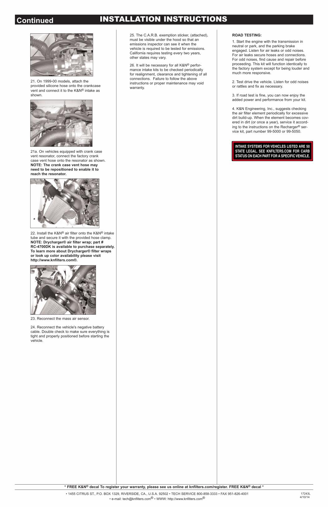
21. On 1999-00 models, attach theprovided silicone hose onto the crankcasevent and connect it to the K&N® intake asshown.
21a. On vehicles equipped with crank casevent resonator, connect the factory crankcase vent hose onto the resonator as shown.NOTE: The crank case vent hose mayneed to be repositioned to enable it toreach the resonator.
24. Reconnect the vehicle's negative batterycable. Double check to make sure everything istight and properly positioned before starting thevehicle.
25. The C.A.R.B. exemption sticker, (attached),must be visible under the hood so that anemissions inspector can see it when thevehicle is required to be tested for emissions.California requires testing every two years,other states may vary.
26. It will be necessary for all K&N® perfor-mance intake kits to be checked periodicallyfor realignment, clearance and tightening of allconnections. Failure to follow the aboveinstructions or proper maintenance may voidwarranty.
17243L4/10/14