5.2 – heating effects of electric currents · filament lamp diode devices for which current...
TRANSCRIPT
Topic 5: Electricity and magnetism5.2 – HEATING EFFECTS OF ELECTRIC
CURRENTS

• When the ends of an electric conductor are at different electric potential, charge flows from one end to the other. Voltage is what causes charge to move in a conductor. Charge moves toward lower potential energy the same way as you would fall from a tree.
• Voltage plays a role similar to pressure in a pipe; to get water to flow there must be a pressure difference between the ends, this pressure difference is produced by a pump
• A battery is like a pump for charge, it provides the energy for pushing the charges around a circuit

• You can have voltage, but without a path (connection) there is no current.
voltage
An electrical
outlet
Current– flow of electric chargeIf I connect a battery to the ends of the copper bar the electrons in the copper will be pulled toward the positive side of the battery and will flow around and around.🡪 this is called current – flow of charge
copper
Duracell+
An electric circuit!

Electric current (symbol I)
• DEF: the rate at which charge flows past a given cross-section.
• measured in amperes (A)
q
◊ the flow of electric charge q that can occur in solids, liquids and gases.
Solids – electrons in metals and graphite, and holes in semiconductorsLiquids – positive and negative ions in molten and aqueous electrolytesGases – electrons and positive ions stripped from gaseous molecules by large potential differences.

Electrical resistance (symbol R)
• The electrons do not move freely through a conductor. As they move they keep bumping into the ions of crystal lattice which either slows them down or bring them to rest.
.
atoms
free electron
(actually positive ions)
path
The resistance is a measure of how hard it is to pass something through a material.

Some very precise resistors are made of wire and are calledwire-wound resistors. And some resistors can be made to vary their resistance by tapping them at various places. These are called variable resistors and potentiometers.Thermistors are temperature- dependent resistors, changing their resistance in response to their temperature.Light-dependent resistors (LDRs) change their resistance in response to light intensity.
Electrical Resistance
A resistor’s working part is usually made of carbon, which is a semiconductor.The less carbon there is, the harder it is for current to flow through the resistor.
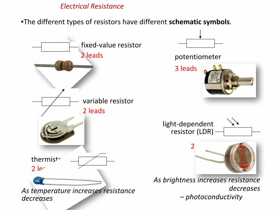
The different types of resistors have different schematic symbols.
fixed-value resistor
variable resistor
potentiometer2 leads
2 leads
3 leads
Electrical Resistance
thermister2 leads
As temperature increases resistance decreases
light-dependent resistor (LDR)
2 leads
As brightness increases resistance decreases
– photoconductivity

A reading of 0.L on an ohmeter means “overload”. The resistance (of the air) is too high to record with the meter.
Electrical resistance R is a measure of how hard it is for current to flow through a material. Resistance is measured in ohms (Ω) using an ohm-meter.
330.4 0.L 0.0 This resistor has a resistance of
330.4 Ω.
Electrical Resistance
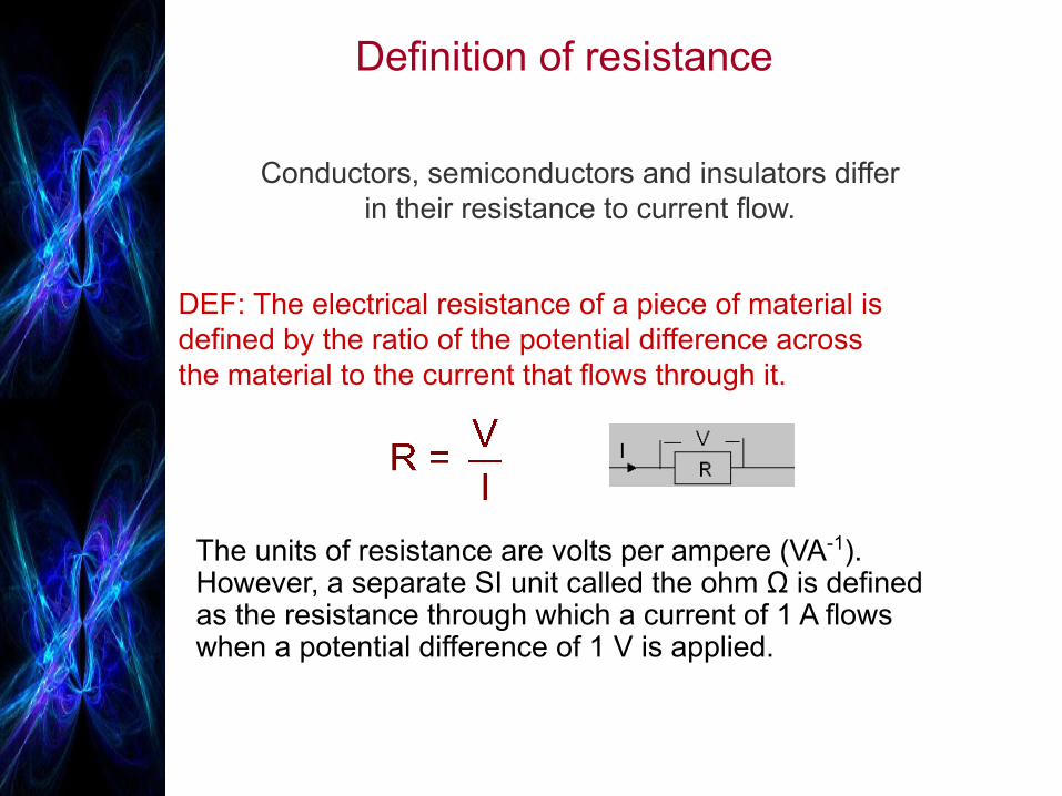
Definition of resistance
The units of resistance are volts per ampere (VA-1).However, a separate SI unit called the ohm Ω is defined as the resistance through which a current of 1 A flows when a potential difference of 1 V is applied.
Conductors, semiconductors and insulators differ in their resistance to current flow.
DEF: The electrical resistance of a piece of material is defined by the ratio of the potential difference across the material to the current that flows through it.

Wires, wires, wires
we ignore the resistance of a connecting wire calculations but resistance of a wire can not be neglected if it is a long, long wire as in the case of iron, washing machine, toaster ….., where it becomes resistor itself.
The resistance of a conducting wire depends on four main factors: • length • cross-sectional area • resistivity • temperature
Factors affecting resistance
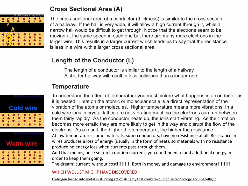
Cross Sectional Area (A)The cross-sectional area of a conductor (thickness) is similar to the cross section of a hallway. If the hall is very wide, it will allow a high current through it, while a narrow hall would be difficult to get through. Notice that the electrons seem to be moving at the same speed in each one but there are many more electrons in the larger wire. This results in a larger current which leads us to say that the resistance is less in a wire with a larger cross sectional area.
Length of the Conductor (L)The length of a conductor is similar to the length of a hallway. A shorter hallway will result in less collisions than a longer one.
TemperatureTo understand the effect of temperature you must picture what happens in a conductor as it is heated. Heat on the atomic or molecular scale is a direct representation of the vibration of the atoms or molecules. Higher temperature means more vibrations. In a cold wire ions in crystal lattice are not vibrating much so the electrons can run between them fairly rapidly. As the conductor heats up, the ions start vibrating. As their motion becomes more erratic they are more likely to get in the way and disrupt the flow of the electrons. As a result, the higher the temperature, the higher the resistance. At low temperatures some materials, superconductors, have no resistance at all. Resistance in wires produces a loss of energy (usually in the form of heat), so materials with no resistance produce no energy loss when currents pass through them. And that means, once set up in motion (current) you don’t need to add additional energy in order to keep them going.The dream: current without cost!!!!!!!!! Both in money and damage to environment!!!!!!!!
WHICH WE JUST MIGHT HAVE DISCOVERED
Hydrogen turned into metal in stunning act of alchemy that could revolutionise technology and spaceflight

Resistance of a wire when the temperature is kept constant is:
The resistivity, ρ (the Greek letter rho), is a value that only depends on the material being used. It is tabulated and you can find it in the books. For example, gold would have a lower value than lead or zinc, because it is a better conductor than they are.The unit is Ω•m.
Of course, resistance depends on the material being used.
In conclusion, we could say that a short fat cold wire makes the best conductor.
If you double the length of a wire, you will double the resistance of the wire.
If you double the cross sectional area of a wire you will cut its resistance in half.

The Greek ρ is the resistivity of the particular material the resistor is made from. It is measured in Ωm.
Resistivities and Temperature Coefficients for Various Materials at 20°Cρ (Ω⋅m) α (C° -1)Material ρ (Ω⋅m) α (C° -1)Material
Conductors Semiconductors
2.82×10⁻⁸ 4.29×10⁻³Aluminum Carbon 3600×10-8 -5.0×10⁻⁴
1.70×10⁻⁸ 6.80×10⁻³Copper Germanium 4.6×10⁻¹ -5.0×10⁻²
10×10-8 6.51×10⁻³Iron Silicon 2.5×10² -7.0×10⁻²
98.4×10⁻⁸ 0.89×10⁻³Mercury
100×10-8 0.40×10⁻³Nichrome Nonconductors
7.8×10⁻⁸ 6.0×10⁻³Nickel Glass 1012
10×10-8 3.93×10⁻³Platinum Rubber 1015
1.59×10⁻⁸ 6.1×10⁻³Silver Wood 1010
5.6×10⁻⁸ 4.5×10⁻³Tungsten
Electrical Resistance
Gold 2.3×10⁻⁸

PRACTICE: What is the resistance of a 0.00200 meter long carbon core resistor having a core diameter of 0.000100 m? Assume the temperature is 20 °C.
r = d / 2 = 0.0001 / 2 = 0.00005 m.A = πr2 = π(0.00005)2 = 7.854×10⁻⁹ m2.From the table ρ = 3600×10-8 Ω m. R = ρL / A = (3600×10-8)(0.002) / 7.854×10-9 = 9.17 Ω.
Resistance Note that resistance depends on temperature. The IBO does not require us to explore this facet of resistivity.
LA

End of Day 1
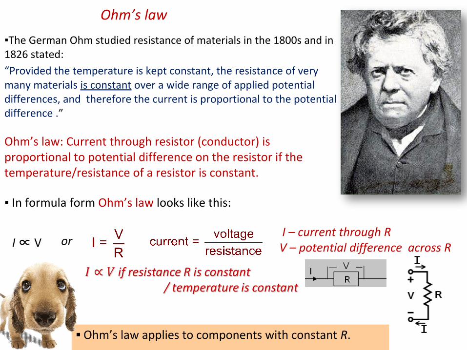
Ohm’s law applies to components with constant R.
The German Ohm studied resistance of materials in the 1800s and in 1826 stated:
“Provided the temperature is kept constant, the resistance of very many materials is constant over a wide range of applied potential differences, and therefore the current is proportional to the potential difference .”
In formula form Ohm’s law looks like this:
I ∝ V
Ohm’s law
Ohm’s law: Current through resistor (conductor) is proportional to potential difference on the resistor if the temperature/resistance of a resistor is constant.
or
I – current through R V – potential difference across R
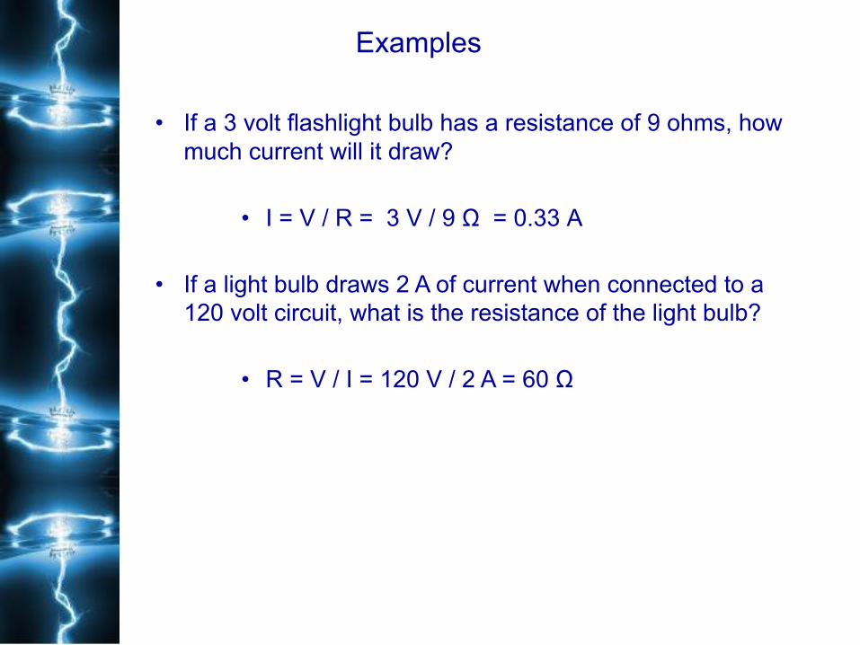
Examples
• If a 3 volt flashlight bulb has a resistance of 9 ohms, how much current will it draw?
• I = V / R = 3 V / 9 Ω = 0.33 A
• If a light bulb draws 2 A of current when connected to a 120 volt circuit, what is the resistance of the light bulb?
• R = V / I = 120 V / 2 A = 60 Ω

Effects of electric current on the BODY- electric shock
Current (A) Effect
0.001 can be felt
0.005 painful
0.010 involuntary muscle contractions (spasms)
0.015 loss of muscle control
0.070if through the heart, serious disruption; probably fatal if current lasts for more than 1 second
questionable circuits: live (hot) wire ? how to avoid being electrified?
1. keep one hand behind the body (no hand to hand current through the body)
2. touch the wire with the back of the hand. Shock causing muscular contraction will not cause their hands to grip the wire.

human body resistance varies: 100 ohms if soaked with salt water; moist skin - 1000 ohms; normal dry skin – 100 000 ohms, extra dry skin – 500 000 ohms.
What would be the current in your body if you touch the terminals of a 12-V battery with dry hands?
I = V/R = 12 V/100 000 Ω = 0.000 12 A quite harmless
But if your hands are moist (fear of IB test?) and you touch 24 V battery, how much current would you draw?
I = V/R = 24 V/1000 Ω = 0.024 A a dangerous amount of current.
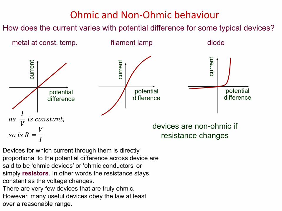
Ohmic and Non-Ohmic behaviourHow does the current varies with potential difference for some typical devices?
curr
ent
potential difference
devices are non-ohmic ifresistance changes
curr
ent
potential difference
curr
ent
potential difference
metal at const. temp. filament lamp diode
Devices for which current through them is directly proportional to the potential difference across device are said to be ‘ohmic devices’ or ‘ohmic conductors’ or simply resistors. In other words the resistance stays constant as the voltage changes.There are very few devices that are truly ohmic. However, many useful devices obey the law at least over a reasonable range.
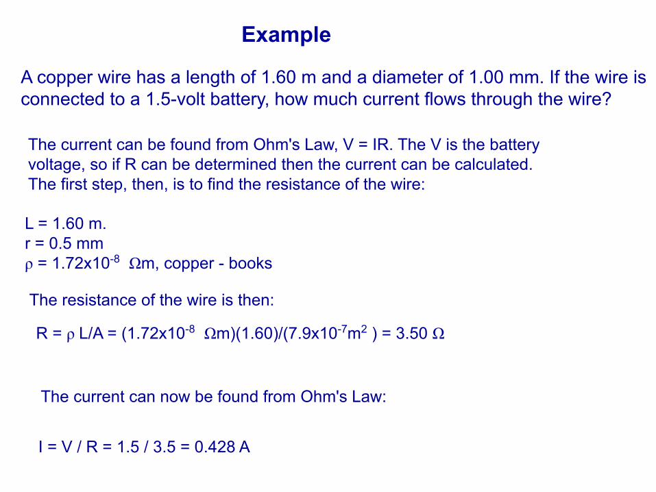
Example
A copper wire has a length of 1.60 m and a diameter of 1.00 mm. If the wire is connected to a 1.5-volt battery, how much current flows through the wire?
The current can be found from Ohm's Law, V = IR. The V is the battery voltage, so if R can be determined then the current can be calculated. The first step, then, is to find the resistance of the wire:
L = 1.60 m.r = 0.5 mmρ = 1.72x10⁻⁸ Ωm, copper - books
The current can now be found from Ohm's Law:
The resistance of the wire is then:
R = ρ L/A = (1.72x10⁻⁸ Ωm)(1.60)/(7.9x10-7m2 ) = 3.50 Ω
I = V / R = 1.5 / 3.5 = 0.428 A
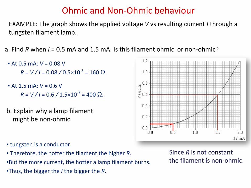
Since R is not constantthe filament is non-ohmic.
Ohmic and Non-Ohmic behaviourEXAMPLE: The graph shows the applied voltage V vs resulting current I through a tungsten filament lamp.
a. Find R when I = 0.5 mA and 1.5 mA. Is this filament ohmic or non-ohmic?
At 0.5 mA: V = 0.08 V
R = V / I = 0.08 / 0.5×10-3 = 160 Ω.
At 1.5 mA: V = 0.6 V
R = V / I = 0.6 / 1.5×10-3 = 400 Ω.
b. Explain why a lamp filament might be non-ohmic.
tungsten is a conductor.
Therefore, the hotter the filament the higher R.
But the more current, the hotter a lamp filament burns.
Thus, the bigger the I the bigger the R.
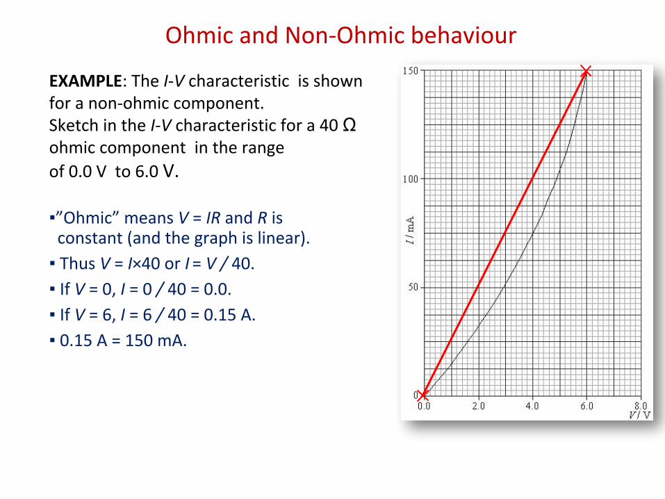
EXAMPLE: The I-V characteristic is shown for a non-ohmic component. Sketch in the I-V characteristic for a 40 Ω ohmic component in the range of 0.0 V to 6.0 V.
”Ohmic” means V = IR and R is constant (and the graph is linear).
Thus V = I×40 or I = V / 40.
If V = 0, I = 0 / 40 = 0.0.
If V = 6, I = 6 / 40 = 0.15 A.
0.15 A = 150 mA.
Ohmic and Non-Ohmic behaviour
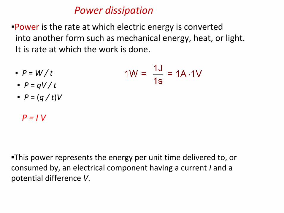
P = I V
Power is the rate at which electric energy is converted into another form such as mechanical energy, heat, or light. It is rate at which the work is done.
P = W / t
P = qV / t
P = (q / t)V
This power represents the energy per unit time delivered to, or consumed by, an electrical component having a current I and a potential difference V.
Power dissipation

PRACTICE: The graph shows the V-I characteristics of a tungsten filamentlamp. What is its power consumption I = 0.5 mA and at I = 1.5 mA?
At 0.5 mA, V = 0.08 V.
P = IV = (0.5×10⁻³)(0.08) = 4.0×10⁻⁵ W.
At 1.5 mA, V = 0.6 V.
P = IV = (1.5×10⁻³)(0.6) = 9.0×10⁻⁴ W.
Power dissipation

End of Day 2

An electric circuit is a set of conductors (like wires) and components (like resistors, lights, etc.) connected to an electrical voltage source (like a cell or a battery) in such a way that current can flow in complete loops.
Here are two circuits consisting of cells, resistors, and wires.
Note current flowing from (+) to (-) in each circuit.
single-loop circuit
triple-loop circuit
Electric circuits

A complete circuit will always contain a cell or a battery.
The schematic diagram of a cell is this:
A battery is just a group of cells connected in series:
If each cell is 1.5 V, then the battery above is 3(1.5) = 4.5 V. What is the voltage of your calculator battery?
The schematic of a fixed-value resistor :
this is really a cell…
this is a battery…
this is the same battery…
Circuits diagrams
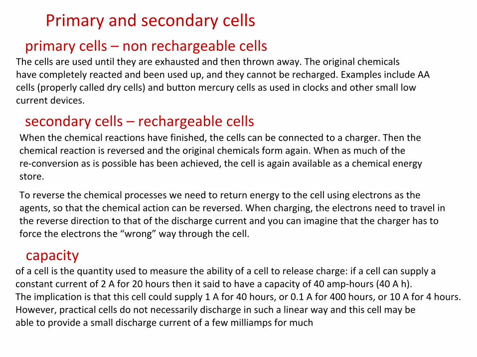
The cells are used until they are exhausted and then thrown away. The original chemicalshave completely reacted and been used up, and they cannot be recharged. Examples include AA cells (properly called dry cells) and button mercury cells as used in clocks and other small low current devices.
Primary and secondary cells
primary cells – non rechargeable cells
When the chemical reactions have finished, the cells can be connected to a charger. Then the chemical reaction is reversed and the original chemicals form again. When as much of the re-conversion as is possible has been achieved, the cell is again available as a chemical energy store.
secondary cells – rechargeable cells
To reverse the chemical processes we need to return energy to the cell using electrons as the agents, so that the chemical action can be reversed. When charging, the electrons need to travel in the reverse direction to that of the discharge current and you can imagine that the charger has to force the electrons the “wrong” way through the cell.
of a cell is the quantity used to measure the ability of a cell to release charge: if a cell can supply a constant current of 2 A for 20 hours then it said to have a capacity of 40 amp-hours (40 A h).The implication is that this cell could supply 1 A for 40 hours, or 0.1 A for 400 hours, or 10 A for 4 hours. However, practical cells do not necessarily discharge in such a linear way and this cell may beable to provide a small discharge current of a few milliamps for much
capacity

Schematic diagrams of each of the following circuits:
Drawing and interpreting circuit diagrams

Electromotive force: emf or ε
The voltage generated by a cell/battery has a special name. It is energy per unit charge and is measured in volts, not newtons, and thus, is not actually a force.
Electromotive force, (ε) is the power supplied to the circuit per unit current
P = I V ⟹ V = P/ I
Power supplied by the source will be dissipated in the circuit:
Electromotive force (ε) is the energy per unit charge made available by an electrical source.
Although, do not be surprised if we still write V instead of ε for cell voltage.
ε = U/q
In short, emf is voltage generated by cell
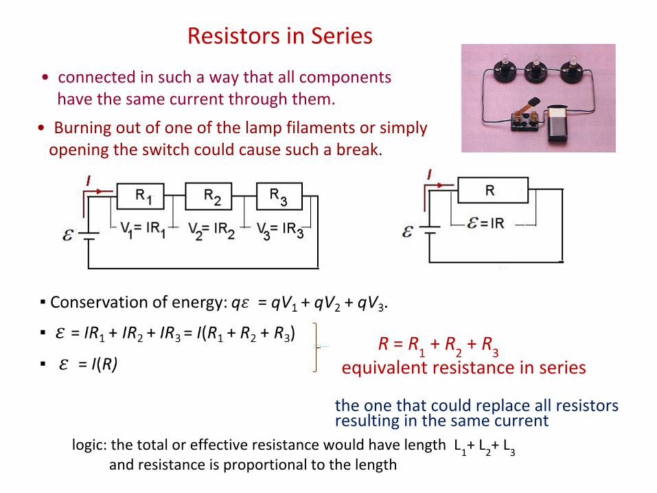
• Burning out of one of the lamp filaments or simply opening the switch could cause such a break.
Resistors in Series
• connected in such a way that all components have the same current through them.
logic: the total or effective resistance would have length L1+ L
2+ L
3 and resistance is proportional to the length
the one that could replace all resistors resulting in the same current
R = R1 + R
2 + R
3
equivalent resistance in series
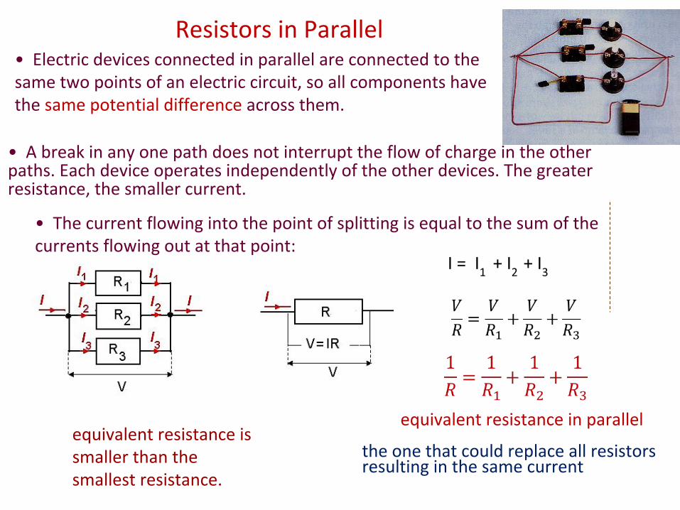
Resistors in Parallel• Electric devices connected in parallel are connected to the same two points of an electric circuit, so all components have the same potential difference across them.
• A break in any one path does not interrupt the flow of charge in the other paths. Each device operates independently of the other devices. The greater resistance, the smaller current.
equivalent resistance is smaller than the smallest resistance.
• The current flowing into the point of splitting is equal to the sum of the currents flowing out at that point:
the one that could replace all resistors resulting in the same current
I = I1
+ I2
+ I3
equivalent resistance in parallel
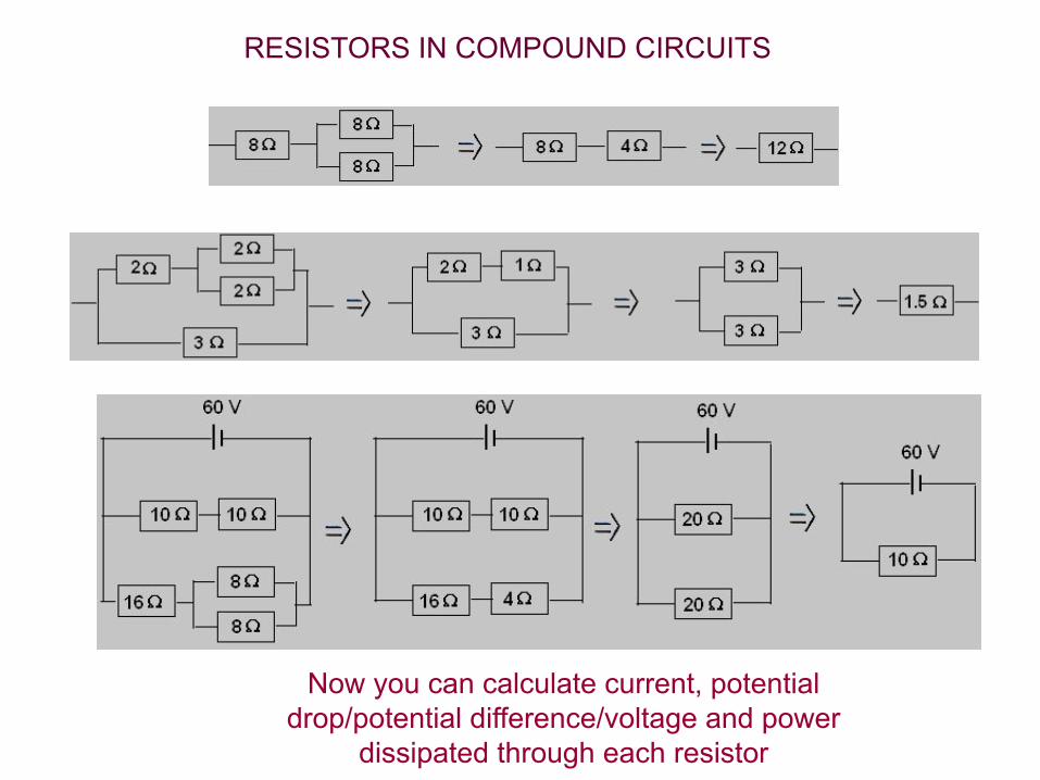
RESISTORS IN COMPOUND CIRCUITS
Now you can calculate current, potential drop/potential difference/voltage and power
dissipated through each resistor

In the mid-nineteenth century, G.R. Kirchoff (1824-1887) stated two simple rules using the laws of conservation of energy and charge to help in the analysis of direct current circuits.
These rules are called Kirchoff’s rules.

‘The sum of the currents flowing into a point in a circuit equals the sum of the currents flowing out at that point’.
1. Junction rule – conservation of charge.
I1
+ I2
= I3
+ I4
+ I5
2. loop rule – conservation of energy.
‘In a closed loop, the sum of the emfs equals the sum of the potential differences’.
energy: qε = qV1 + qV
2 + qV
3
Energy supplied by cell equals the energy released in this closed path

R1
R2
R3
ε
Resistors in seriesThree resistors of 330 Ω each are connected to a 6.0 V battery in series
What is the voltage and current on each resistor?
In series the V’s are different if the R’s are different.
R = R1 + R
2 + R
3 R = 330 + 330 + 330 = 990 Ω
I = V / R = 6 / 990 = 0.0061 A
The current I = 0.0061 A is the same in each resistor.
voltage/potential difference across each resistor: V = I R
1 = I R
2 = I R
3 = (0.0061)(330)
= 2.0 V
Resistors in series and parallel
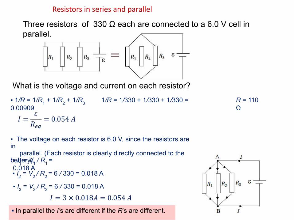
What is the voltage and current on each resistor?
In parallel the I’s are different if the R’s are different.
1/R = 1/R1 + 1/R2 + 1/R3 1/R = 1/330 + 1/330 + 1/330 = 0.00909
The voltage on each resistor is 6.0 V, since the resistors are in parallel. (Each resistor is clearly directly connected to the battery). I1 = V1 / R1 = 0.018 A I2 = V2 / R2 = 6 / 330 = 0.018 A
Three resistors of 330 Ω each are connected to a 6.0 V cell in parallel.
R = 110 Ω
I3 = V3 / R3 = 6 / 330 = 0.018 A
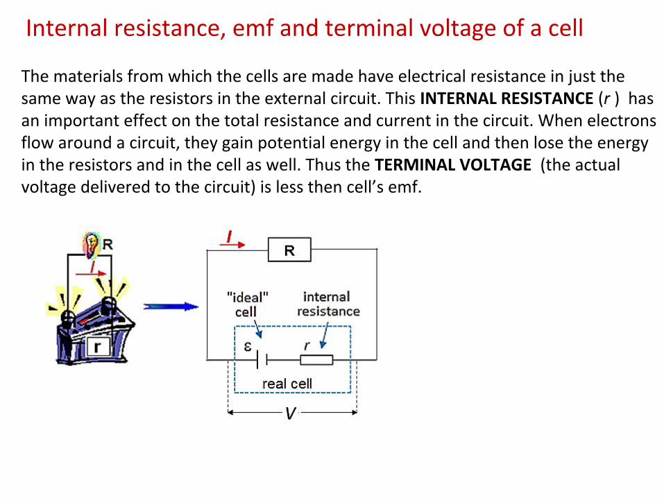
The materials from which the cells are made have electrical resistance in just the same way as the resistors in the external circuit. This INTERNAL RESISTANCE (r ) has an important effect on the total resistance and current in the circuit. When electrons flow around a circuit, they gain potential energy in the cell and then lose the energy in the resistors and in the cell as well. Thus the TERMINAL VOLTAGE (the actual voltage delivered to the circuit) is less then cell’s emf.
Internal resistance, emf and terminal voltage of a cell
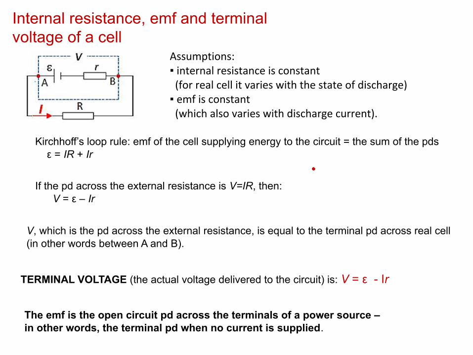
Internal resistance, emf and terminal voltage of a cell
Assumptions: internal resistance is constant (for real cell it varies with the state of discharge) emf is constant (which also varies with discharge current).
Kirchhoff’s loop rule: emf of the cell supplying energy to the circuit = the sum of the pds ε = IR + Ir
If the pd across the external resistance is V=IR, then: V = ε – Ir
V, which is the pd across the external resistance, is equal to the terminal pd across real cell (in other words between A and B).
The emf is the open circuit pd across the terminals of a power source –in other words, the terminal pd when no current is supplied.
TERMINAL VOLTAGE (the actual voltage delivered to the circuit) is: V = ε - Ir
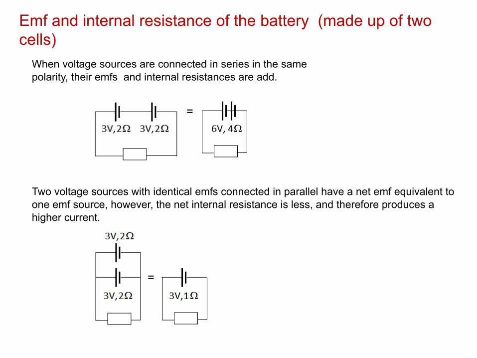
When voltage sources are connected in series in the same polarity, their emfs and internal resistances are add.
Two voltage sources with identical emfs connected in parallel have a net emf equivalent to one emf source, however, the net internal resistance is less, and therefore produces a higher current.
Emf and internal resistance of the battery (made up of two cells)

Summary:
I1
+ I2
= I3
+ I4
+ I5
Power dissipated in resistor R: P = IV
I – current through resistor, V – potential difference across R

Find power of the source, current in each resistor, terminal potential, potential drop across each resistor and power dissipated in each resistor.
1. step: find total/equivalent resistance
Req
= 120 Ω
I1 = ε ⁄ Req = 0.3 A
potential dropsV = IR
power dissipatedP = IV
80 Ω 0.3x80 = 24 V 0.3x24 = 7.2 W100 Ω 0.1x100 = 10 V 0.1x10 = 1 W50 Ω 0.2x50 = 10 V 0.2x10 = 2 W6.7 Ω 0.3x6.7 = 2 V 0.3x2 = 0.6 W
ε = Σ all potential drops: 36 V = 2 V + 24 V + 10 Vpower dissipated in the circuit =power of the source0.6 + 2 + 1 + 7.2 = 0.3x36
control:

In practical use, we need to be able to measure currents through components and voltages across various components in electrical circuits. To do this, we use AMMETERS and VOLTMETERS.
Ammeters and voltmeters
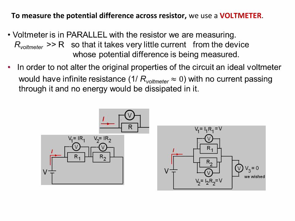
To measure the potential difference across resistor, we use a VOLTMETER.

Be sure to position the voltmeter across the desired resistor in parallel.
1.06
Circuit diagrams - voltmeters are connected in parallel
Draw a schematic diagram for this circuit
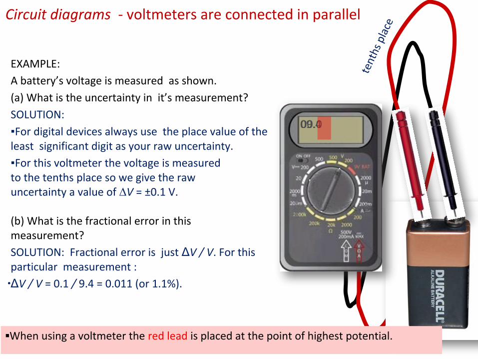
EXAMPLE:
A battery’s voltage is measured as shown.
(a) What is the uncertainty in it’s measurement?
SOLUTION:
For digital devices always use the place value of the least significant digit as your raw uncertainty.
For this voltmeter the voltage is measured to the tenths place so we give the raw uncertainty a value of ∆V = ±0.1 V.
Circuit diagrams - voltmeters are connected in parallel
tent
hs p
lace
09.400.0
(b) What is the fractional error in this measurement?
SOLUTION: Fractional error is just ΔV / V. For this particular measurement :
∙ΔV / V = 0.1 / 9.4 = 0.011 (or 1.1%).
When using a voltmeter the red lead is placed at the point of highest potential.

Consider the simple circuit of battery, lamp, and wire.To measure the voltage in the circuit we merely connect the
voltmeter while the circuit is in operation.
01.600.0
celllampvoltmeterin parallel
Circuit diagrams - voltmeters are connected in parallel
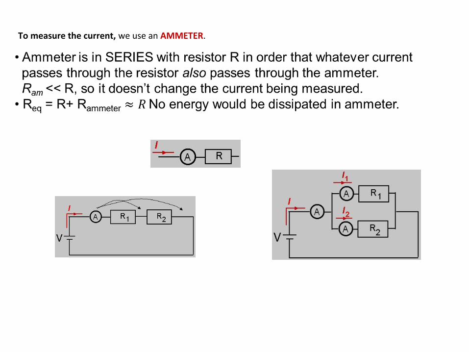
To measure the current, we use an AMMETER.

00.200.0
celllamp
ammeterin series
Circuit diagrams - ammeters are connected in series
To measure the current of the circuit we must break the circuit and insert the ammeter so that it intercepts all of the electrons that normally travel through the circuit.
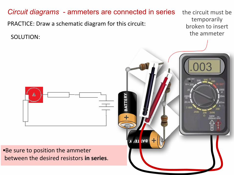
Be sure to position the ammeter between the desired resistors in series.
.003
the circuit must be temporarily
broken to insert the ammeter
Circuit diagrams - ammeters are connected in seriesPRACTICE: Draw a schematic diagram for this circuit:
SOLUTION:
Potential divider circuits
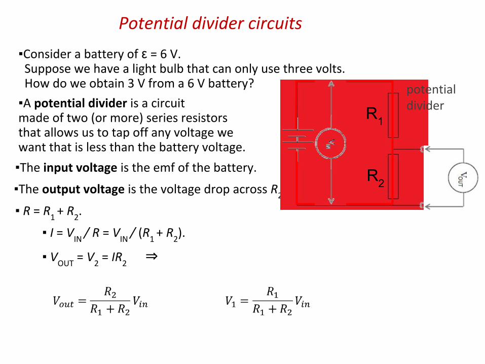
Consider a battery of ε = 6 V. Suppose we have a light bulb that can only use three volts. How do we obtain 3 V from a 6 V battery?
A potential divider is a circuit made of two (or more) series resistors that allows us to tap off any voltage we want that is less than the battery voltage.
The input voltage is the emf of the battery.
R = R1
+ R2.
The output voltage is the voltage drop across R2.
potential dividerR1
R2
I = VIN
/ R = VIN
/ (R1
+ R2).
VOUT
= V2 = IR
2 ⇒
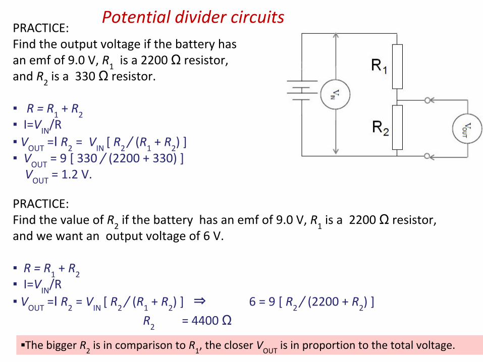
Potential divider circuitsPRACTICE: Find the output voltage if the battery has an emf of 9.0 V, R
1 is a 2200 Ω resistor,
and R2 is a 330 Ω resistor.
R = R1 + R
2
I=VIN
/R V
OUT =I R
2 = V
IN [ R
2 / (R
1 + R
2) ]
VOUT
= 9 [ 330 / (2200 + 330) ] V
OUT = 1.2 V.
The bigger R2 is in comparison to R
1, the closer V
OUT is in proportion to the total voltage.
PRACTICE: Find the value of R
2 if the battery has an emf of 9.0 V, R
1 is a 2200 Ω resistor,
and we want an output voltage of 6 V.
R = R1 + R
2
I=VIN
/R V
OUT =I R
2 = V
IN [ R
2 / (R
1 + R
2) ] ⇒ 6 = 9 [ R
2 / (2200 + R
2) ]
R2 = 4400 Ω
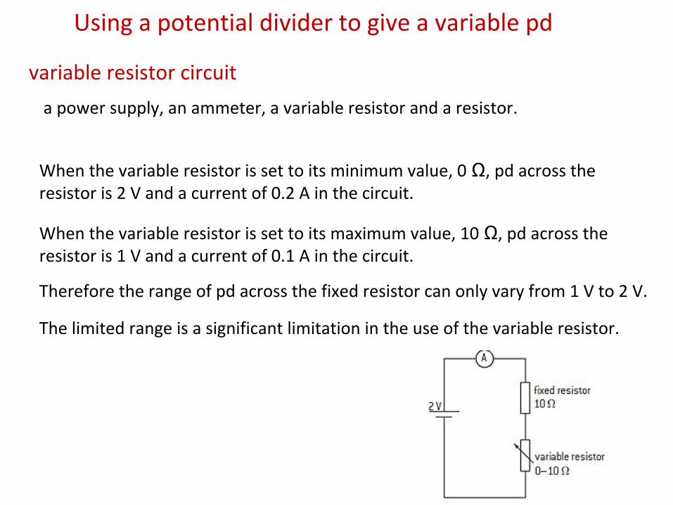
Using a potential divider to give a variable pd
a power supply, an ammeter, a variable resistor and a resistor.
When the variable resistor is set to its minimum value, 0 Ω, pd across the resistor is 2 V and a current of 0.2 A in the circuit.
When the variable resistor is set to its maximum value, 10 Ω, pd across the resistor is 1 V and a current of 0.1 A in the circuit.
Therefore the range of pd across the fixed resistor can only vary from 1 V to 2 V.
The limited range is a significant limitation in the use of the variable resistor.
variable resistor circuit
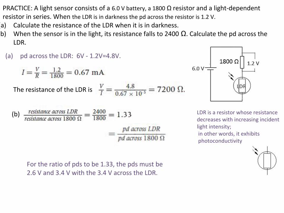
PRACTICE: A light sensor consists of a 6.0 V battery, a 1800 Ω resistor and a light-dependent resistor in series. When the LDR is in darkness the pd across the resistor is 1.2 V.
(a) Calculate the resistance of the LDR when it is in darkness. (b) When the sensor is in the light, its resistance falls to 2400 Ω. Calculate the pd across the
LDR.
(a) pd across the LDR: 6V - 1.2V=4.8V.
The resistance of the LDR is
(b)
For the ratio of pds to be 1.33, the pds must be 2.6 V and 3.4 V with the 3.4 V across the LDR.
LDR is a resistor whose resistance decreases with increasing incident light intensity; in other words, it exhibits photoconductivity
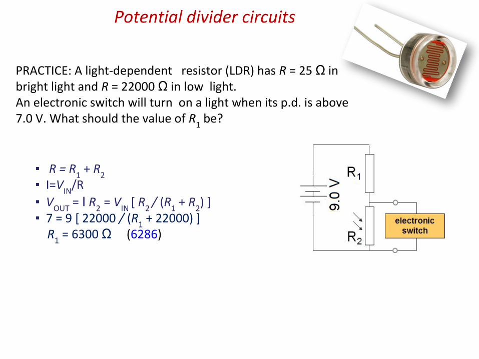
PRACTICE: A light-dependent resistor (LDR) has R = 25 Ω in bright light and R = 22000 Ω in low light. An electronic switch will turn on a light when its p.d. is above 7.0 V. What should the value of R
1 be?
Potential divider circuits
R = R1 + R
2
I=VIN
/R V
OUT = I R
2 = V
IN [ R
2 / (R
1 + R
2) ]
7 = 9 [ 22000 / (R1 + 22000) ]
R1 = 6300 Ω (6286)
Potential divider circuits
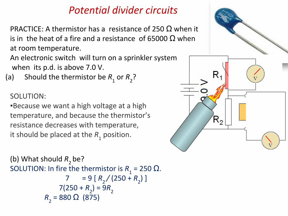
PRACTICE: A thermistor has a resistance of 250 Ω when it is in the heat of a fire and a resistance of 65000 Ω when at room temperature. An electronic switch will turn on a sprinkler system when its p.d. is above 7.0 V.
(a) Should the thermistor be R1 or R
2?
SOLUTION:Because we want a high voltage at a high temperature, and because the thermistor’s resistance decreases with temperature, it should be placed at the R
1 position.
(b) What should R2
be?SOLUTION: In fire the thermistor is R
1 = 250 Ω.
7 = 9 [ R2
/ (250 + R2) ]
7(250 + R2) = 9R
2 R
2 = 880 Ω (875)

PRACTICE: A filament lamp is rated at “4.0 V, 0.80 W”
on its package. The potentiometer has a resistance from X to Z of 24 Ω and has linear variation.
(a) Sketch the variation of the p.d. V vs. the current I for a typical filament lamp. Is it ohmic?
SOLUTION: Since the temperature increases with the current, so does the resistance.
But from V = IR we see that R = V / I, which is the slope.
Thus the slope should increase with I.
V
I
ohmic means linear
non-ohmic
Potential divider circuits
Since we need VOUT
= 4 V, and since VIN
= 6 V, the contact must be adjusted above the Y.
(b) The potentiometer is adjusted so that the meter shows 4.0 V. Will it’s contact be above Y, below Y, or exactly on Y?
SOLUTION: The circuit is acting like a potential divider with R
1 being the resistance between X and Y
and R2 being the resistance between Y and Z.
R1
R2

PRACTICE: A filament lamp is rated at “4.0 V, 0.80 W” on its package. The potentiometer has a resistance from X to Z of 24 Ω and has linear variation.
R1
R2
(c) The potentiometer is adjusted so that the meter shows 4.0 V. What are the current and the resistance of the lamp at this instant?SOLUTION: P = 0.80 W and V = 4.0 V. P = IV ⇒ 0.8 = I(4) ⇒ I = 0.20 A.
V = IR ⇒ 4 = 0.2R ⇒ R = 20. Ω.
You could also use P = I 2R for this last one.
(d) The potentiometer is adjusted so that the meter shows 4.0 V. What is the resistance of the Y-Z portion of the potentiometer?SOLUTION: Let R
1 = X to Y and R
2 = Y to Z resistance.
Then R1 + R
2 = 24 so that R
1 = 24 – R
2.
From VOUT
= VIN
[ R2
/ (R1 + R
2) ] we get
4 = 7 [ R2
/ (24 – R2 + R
2) ] → R
2 = 14 Ω (13.71).

PRACTICE: A filament lamp is rated at “4.0 V, 0.80 W” on its package. The potentiometer has a resistance from X to Z of 24 Ω and has linear variation.
R1
R2
(e) The potentiometer is adjusted so that the meter shows 4.0 V. What is the current in the Y-Z portion of the potentiometer?SOLUTION:
V2 = 4.0 V because it is in parallel with the lamp.
I2 = V
2 / R
2
= 4 / 13.71 = 0.29 A
(f) The potentiometer is adjusted so that the meter shows 4.0 V. What is the current in the ammeter?SOLUTION: The battery supplies two currents.
The red current is 0.29 A because it is the I2 we just calculated in (e).
The green current is 0.20 A found in (c).
The ammeter has both so I = 0.29 + 0.20 = 0.49 A.
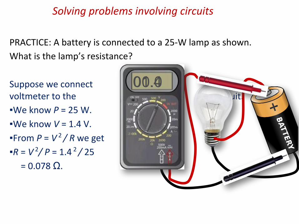
PRACTICE: A battery is connected to a 25-W lamp as shown.
What is the lamp’s resistance?
Suppose we connect a voltmeter to the circuit.
We know P = 25 W.
We know V = 1.4 V.
From P = V 2 / R we get
R = V 2/ P = 1.4 2 / 25
= 0.078 Ω.
01.400.0
Solving problems involving circuits
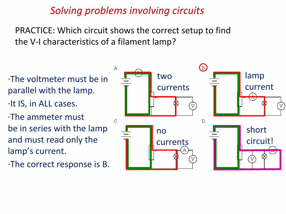
·The voltmeter must be in parallel with the lamp.
·It IS, in ALL cases.
·The ammeter must be in series with the lamp and must read only the lamp’s current.
·The correct response is B.
two currents
no currents
short circuit!
lamp current
PRACTICE: Which circuit shows the correct setup to find the V-I characteristics of a filament lamp?
Solving problems involving circuits

PRACTICE: A non-ideal voltmeter is used to measure the p.d. of the 20 kΩ resistor as shown. What will its reading be?
SOLUTION: There are two currents in the circuit because the voltmeter does not have a high enough resistance to prevent the green one from flowing.
The 20 kΩ resistor is in parallel with the 20 kΩ:
1 / R = 1 / 20000 + 1 / 20000 = 2 / 20000.
R = 20000 / 2 = 10 kΩ.
But then we have two 10 kΩ resistors in series and each takes half the battery voltage, or 3 V.
equivalent cktSolving problems involving circuits
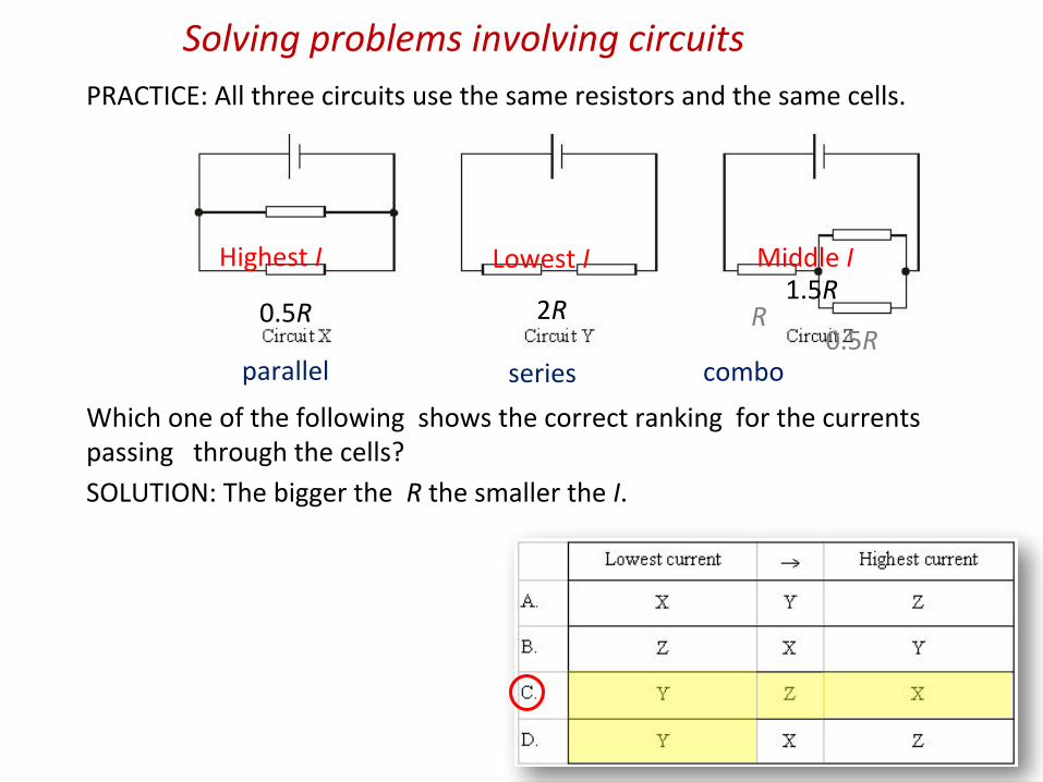
PRACTICE: All three circuits use the same resistors and the same cells.
Which one of the following shows the correct ranking for the currents passing through the cells?
SOLUTION: The bigger the R the smaller the I.
2R0.5R R0.5R
1.5R
parallel series combo
Highest I Lowest I Middle I
Solving problems involving circuits
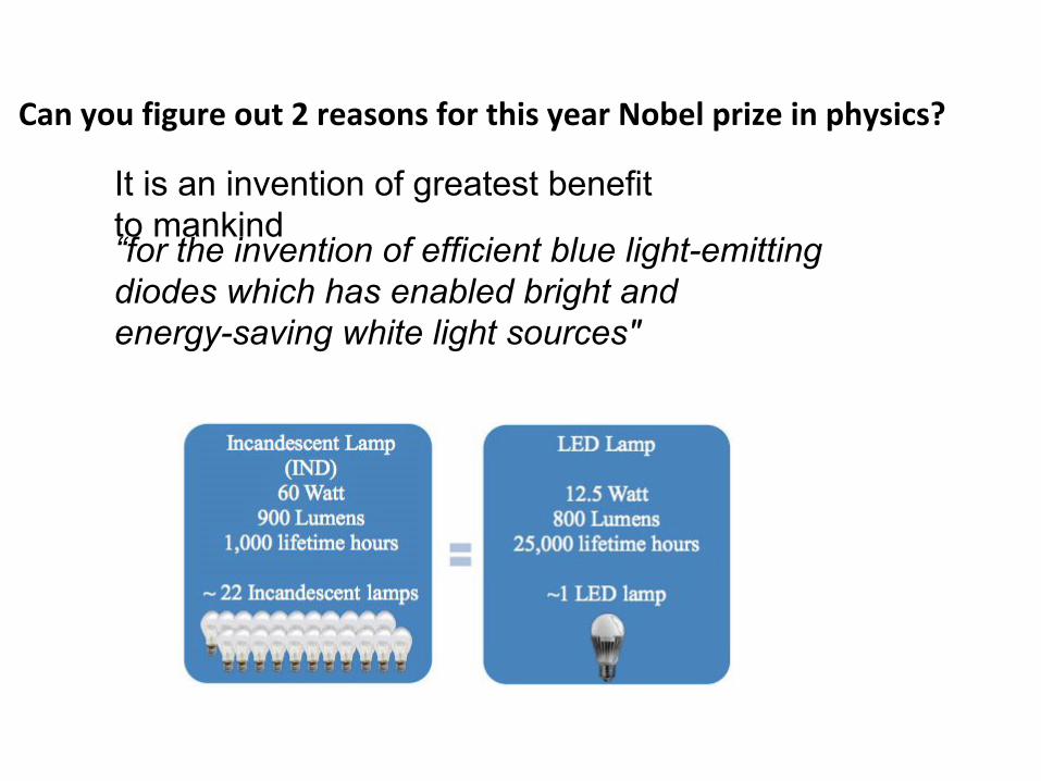
Can you figure out 2 reasons for this year Nobel prize in physics?
“for the invention of efficient blue light-emitting diodes which has enabled bright and energy-saving white light sources"
It is an invention of greatest benefit to mankind
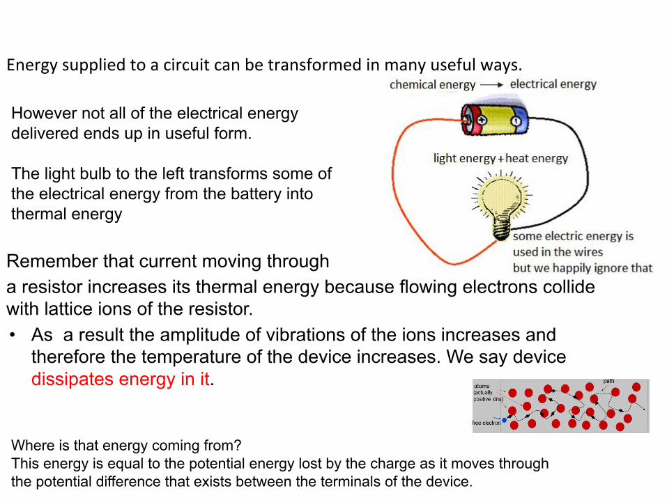
Energy supplied to a circuit can be transformed in many useful ways.
Remember that current moving through a resistor increases its thermal energy because flowing electrons collide with lattice ions of the resistor.• As a result the amplitude of vibrations of the ions increases and
therefore the temperature of the device increases. We say device dissipates energy in it.
However not all of the electrical energy delivered ends up in useful form.
The light bulb to the left transforms some of the electrical energy from the battery into thermal energy
Where is that energy coming from? This energy is equal to the potential energy lost by the charge as it moves through the potential difference that exists between the terminals of the device.

The main advantage is efficiency. In conventional tungsten/wolfram bulbs, the light-production process involves generating a lot of heat (the filament must be warmed). This is completely wasted energy, unless you're using the lamp as a heater, because a huge portion of the available electricity isn't going toward producing visible light. LEDs generate very little heat, relatively speaking. A much higher percentage of the electrical power is going directly to generating light, which cuts down on the electricity demands considerably.
https://www.youtube.com/watch?v=oCEKMEeZXug

DEF: Power is the rate at which electric energy is converted into another form such as mechanical energy, heat, or light.
Power dissipation in resistors
If a vacuum cleaner has a power rating of 500 W, it meansit is converting electrical energy to mechanical, soundand heat energy at the rate of 500 J s-1. A 60 W light globe converts electrical energy to light and heat energy at the rate of 60 J s -1.
Appliance Power rating
Blow heater 2 kWKettle 1.5 kWToaster 1.2 kWIron 850 WVacuum cleaner 1.2 kWTelevision 250 W
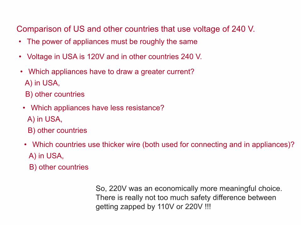
Comparison of US and other countries that use voltage of 240 V. • The power of appliances must be roughly the same
• Voltage in USA is 120V and in other countries 240 V.
• Which appliances have to draw a greater current? A) in USA, B) other countries
• Which appliances have less resistance? A) in USA, B) other countries
• Which countries use thicker wire (both used for connecting and in appliances)? A) in USA, B) other countries
So, 220V was an economically more meaningful choice. There is really not too much safety difference between getting zapped by 110V or 220V !!!

Direct Current (DC) electric circuits• a circuit containing a battery is a DC circuit• in a DC circuit the current always flows in the same direction.
Duracell
+
• a circuit must provide a closed path for the current to circulate around
• when the electrons pass through the light bulb they loose energy 🡪 the bulb gives light and heats up
• the battery is like a pump that re-energizes them each time they pass through it

Direction of Current
Current is defined as the direction positive charges would flow • From + side of battery to – side of battery
Fun FactBenjamin Franklin defined current in this manner long before we knew much about charges.
Now, we know that positive charges stay put and negative charges flow. So, electrons actually flow opposite current.
hystoric explanationclick me
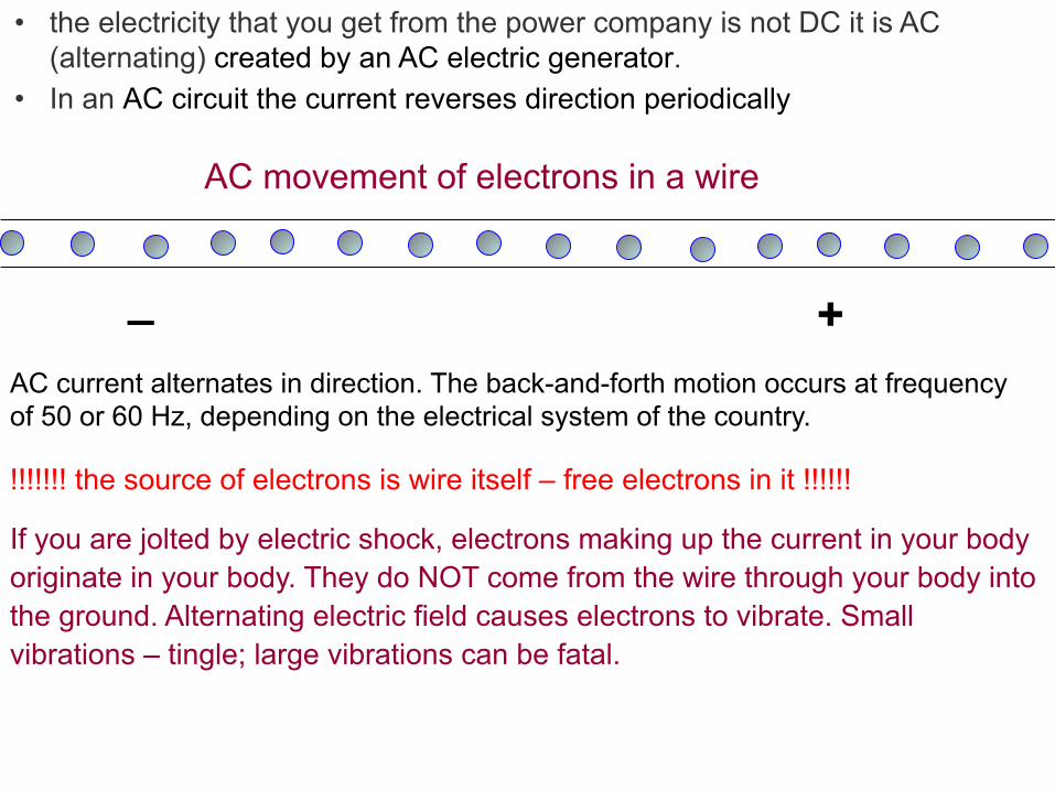
• the electricity that you get from the power company is not DC it is AC (alternating) created by an AC electric generator.
• In an AC circuit the current reverses direction periodically
_ +AC current alternates in direction. The back-and-forth motion occurs at frequency of 50 or 60 Hz, depending on the electrical system of the country.
AC movement of electrons in a wire
!!!!!!! the source of electrons is wire itself – free electrons in it !!!!!! If you are jolted by electric shock, electrons making up the current in your body originate in your body. They do NOT come from the wire through your body into the ground. Alternating electric field causes electrons to vibrate. Small vibrations – tingle; large vibrations can be fatal.

curr
ent
time
AC
curr
ent
time
DC
How does the voltage and current change in time?
DC does not change direction over time;
the actual voltage in a 120-V AC circuit varies between +170V and -170V peaks.
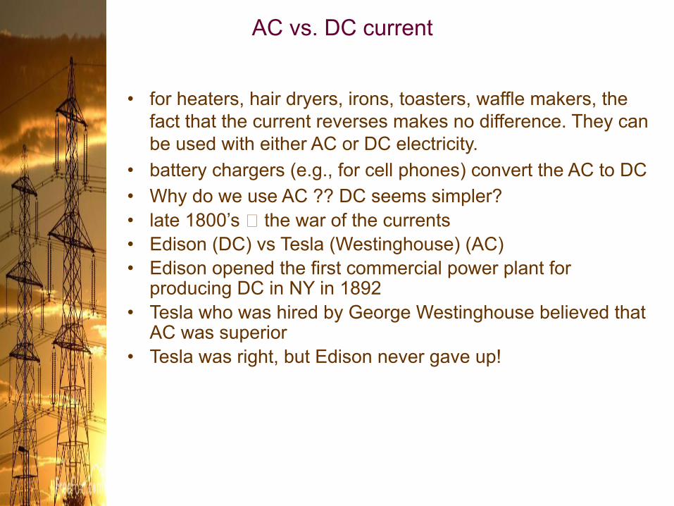
AC vs. DC current
• for heaters, hair dryers, irons, toasters, waffle makers, the fact that the current reverses makes no difference. They can be used with either AC or DC electricity.
• battery chargers (e.g., for cell phones) convert the AC to DC• Why do we use AC ?? DC seems simpler?• late 1800’s 🡪 the war of the currents• Edison (DC) vs Tesla (Westinghouse) (AC)• Edison opened the first commercial power plant for
producing DC in NY in 1892• Tesla who was hired by George Westinghouse believed that
AC was superior• Tesla was right, but Edison never gave up!

Why AC is better than DC• DC power is provided at one voltage only• There is energy lost in a power line due to dissipation of energy to heat
throughout the length of the cable.• So DC power plants must be close to users• The major advantage of AC: AC voltages can be transformed to higher or
lower voltages (can be stepped up or down to provide any voltage required) by the use of the transformers.
• This means that low voltage produced in a generator can be stepped up to higher voltage. High voltages in power lines are actually needed for sending power from one place to another over great distances.
• Power is equal to the current times the voltage. That means that if you want to send a lot of power you can use: a) high current b) high voltage
• if you use high current, resistance should be small. To reduce the resistance of power lines becomes very expensive since, in order to do this, bigger cables must be used (heavier cables aren’t very safe either).
• To avoid a lot of the power to be lost to the resistance in the wires it is much better to use high voltage since the currents are smaller then!

• Electrical energy sent at high voltage over great distances from the power station can be eventually reduced to a safer voltage for use in the house.
• Some long distance power lines use voltages of more than 500,000 V
• AC plants can be far outside cities• by 1895 DC was out and AC was in

Paying for electricity• You pay for the total amount of electrical energy (not power) that is
used each month• In Irving the cost of electric energy used is 12 ¢ per kilowatt-hour. • How do we get kilowatt-hour and what is that? • Power = energy/time
Physicists measure energy in joules, but utility companies customarily charge energy in units of kilowatt-hours (kW h), where :
Kilowatt-hour (kWh) = 103 W x 3600 s
1 kWh = 3.6 x 10⁶ J
1W x 1s = 1J

•
amount of power in kW used by the clock over 30 days
E = Pt ; where time is in hours and P is in kW
cost = E($.12)
Cost = $0.10
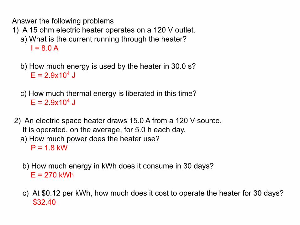
Answer the following problems1) A 15 ohm electric heater operates on a 120 V outlet. a) What is the current running through the heater? I = 8.0 A b) How much energy is used by the heater in 30.0 s? E = 2.9x10⁴ J c) How much thermal energy is liberated in this time? E = 2.9x10⁴ J 2) An electric space heater draws 15.0 A from a 120 V source. It is operated, on the average, for 5.0 h each day. a) How much power does the heater use? P = 1.8 kW
b) How much energy in kWh does it consume in 30 days? E = 270 kWh
c) At $0.12 per kWh, how much does it cost to operate the heater for 30 days? $32.40
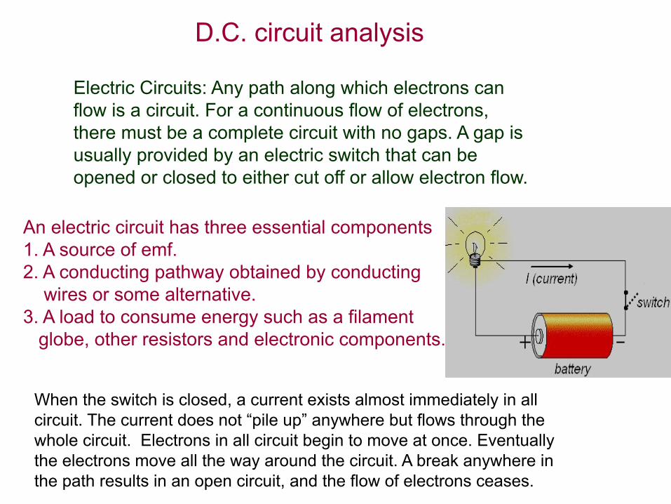
D.C. circuit analysis
An electric circuit has three essential components1. A source of emf.2. A conducting pathway obtained by conducting wires or some alternative.3. A load to consume energy such as a filament globe, other resistors and electronic components.
Electric Circuits: Any path along which electrons can flow is a circuit. For a continuous flow of electrons, there must be a complete circuit with no gaps. A gap is usually provided by an electric switch that can be opened or closed to either cut off or allow electron flow.
When the switch is closed, a current exists almost immediately in all circuit. The current does not “pile up” anywhere but flows through the whole circuit. Electrons in all circuit begin to move at once. Eventually the electrons move all the way around the circuit. A break anywhere in the path results in an open circuit, and the flow of electrons ceases.

Because resistance is directly proportional to the length of a resistor, a variable resistor also known as a potentiometer or as a “pot” can also be used to control the potential difference across some device.
Potentiometer
Pots have a rotating wheel mounted in plastic and they are commonly used as volume and tone controls in sound systems. They can be made from wire, metal oxides or carbon compounds.
Sliding contact A can connect anywhere from one end to the other of the resistor chain. This way it can control voltage across a device and therefore the current through it, from maximum down to zero.
1. step is to do a circuit without device and then adjust point A in such a way that there is no current passing through potentiometer.
Potential difference across potentiometer is 6 V.
For some other battery point A would be somewhere else. If you include a lamp into circuit and the pointer is at A, potential difference across the lamp is zero. However, if the pointer is moved up to two-thirds the length of the potentiometer as in the figure, then the output voltage across the filament lamp would be
⅔ × 6V = 4V.