5 viii august 2017
TRANSCRIPT

5 VIII August 2017
http://doi.org/10.22214/ijraset.2017.8241
International Journal for Research in Applied Science & Engineering Technology (IJRASET) ISSN: 2321-9653; IC Value: 45.98; SJ Impact Factor:6.887
Volume 5 Issue VIII, August 2017- Available at www.ijraset.com
1698 ©IJRASET (UGC Approved Journal): All Rights are Reserved
Design and Optimization of Drafe Tube to Increase the Efficiency by Varying the Geometry of the
Draft Tube Outlet Vishwanath1, Yogesh M2, Basavaraj Kakkalmeli3, Dr. G Harish4
123PG Student, 4Professor, Department of Mechanical Engineering, UVCE, Bangalore 01, India
Abstract: To increase the performance of hydroelectric power plant it is necessary to optimize the design of draft tube for uniformity of flow. Draft tube helps to convert the exit velocity head into pressure or potential head. Different geometries of draft tube have been created by changing the lengths .The numerical analysis have been done by using ANSYS CFX code and optimum values of length and diffuser angle are found for the maximum efficiency and head recovery for given boundary conditions. L/D ratio of each model will be changed and analysis has been done, whichever gives more draft tube efficiency and more head recovery will be optimized. Keywords: Draft tube,inlet,outlet,velocity head, pressure head, efficiency.
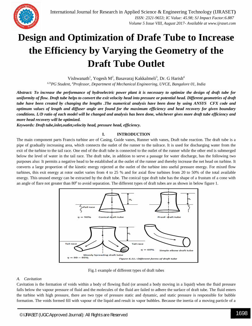
I. INTRODUCTION The main component parts Francis turbine are of Casing, Guide vanes, Runner with vanes, Draft tube reaction. The draft tube is a pipe of gradually increasing area, which connects the outlet of the runner to the tailrace. It is used for discharging water from the exit of the turbine to the tail race. One end of the draft tube is connected to the outlet of the runner while the other end is submerged below the level of water in the tail race. The draft tube, in addition to serve a passage for water discharge, has the following two purposes also: It permits a negative head to be established at the outlet of the runner and thereby increase the net head on turbine. It converts a large proportion of the kinetic energy rejected at the outlet of the turbine into useful pressure energy. For mixed flow turbines, this exit energy at rotor outlet varies from 4 to 25 % and for axial flow turbines from 20 to 50% of the total available energy. This unused energy can be extracted by the draft tube. The conical type draft tube has the shape of a frustum of a cone with an angle of flare not greater than 800 to avoid separation. The different types of draft tubes are as shown in below figure 1.
Fig.1 example of different types of draft tubes
A. Cavitation Cavitation is the formation of voids within a body of flowing fluid (or around a body moving in a liquid) when the fluid pressure falls below the vapour pressure of fluid and the molecules of the fluid are failed to adhere the surface of draft tube. The fluid enters the turbine with high pressure, there are two type of pressure static and dynamic, and static pressure is responsible for bubble formation. The voids formed fill with vapour of the liquid and result in vapor bubbles. Because the inertia of a moving particle of a

International Journal for Research in Applied Science & Engineering Technology (IJRASET) ISSN: 2321-9653; IC Value: 45.98; SJ Impact Factor:6.887
Volume 5 Issue VIII, August 2017- Available at www.ijraset.com
1699 ©IJRASET (UGC Approved Journal): All Rights are Reserved
liquid varies with the square of the velocity, because the greater the inertia, the greater the pressure required to force the particles to take a curved path, it becomes obvious that cavitation is associated with three conditions: high-velocity flow, low pressures, and abrupt changes in the direction of the flow.
II. LITERATURE REVIEW Oliver KIRSCHNER (1) has presented swirling flow in a straight cone draft tube, axi-symmetric flow analysis and made comparison with circumferentially averaged PIV measurements concluded that accurate swirling flow numerical results heavily rely on the draft tube cone inlet boundary conditions corresponding to the swirling flow downstream the turbine runner blades. P. Rudolf (2) did simulation for fluid flowing inside a straight line diffuser for different velocities. Two different types of vortices are determined, the first one is thin vortex with lower amplitude of pressure and high frequency. Kai Kuppinger (3) after an accurate analysis the fluid significantly high pressure losses were found by redesigning the draft tubes passive ways to improve the particular flow and therefore improves the efficiency of the draft tube. O. Kirschner, A. Ruprecht (4) did numerical prediction of unsteady flow structures and flow phenomena like a vortex rope by using CFD became possible with the fast development of computer performance. Dr. Ruchi Khare, Dr. Vishnu Prasad, Mitrasen Verma (5) observed, the optimum performance of draft tube is an important aspect in the design of hydraulic turbine, varying the shape and size of the draft tube. The recovery of kinetic energy leaving the runner determines the performance of draft tubes. The cross-sectional area at exit of draft tube is dependent of length and angle of diffuser and must be chosen to ensure maximum recovery with minimum loss. Conical draft tubes gives improved efficiency in comparison to elbow draft tubes because of more recovery of vortex flow au outlet of runner.
III. METHODOLOGY Numerical analysis is carried on draft tubes obtained by varying the length and geometry at the outlet efficiency is calculated and optimum geometry with high efficiency is determined. Here we are choosing divergence angle 4⁰,5⁰and6⁰ then we are keeping L/D ratio as 2.4, and 5 whichever gives high draft tube efficiency and more head recovery will be optimized. Applying Bernoulli’s equation at inlet and outlet Z1+P1/w+ (V1
2)/2g= Z2+p2/w+ (V22/2g) +hL
Where hL is the loss of energy head in the draft tube Taking P2/w=H atm=10.3mts of water P1/w=H atm-L-((V2
2-V32/2g)-hL)).
The quantity ((V22-V3
2/2g)-hL)). Is called dynamic head The conditions of flow should be so designed that p1/w shall not become less than vapour pressure head. If pressure at inlet is more than outlet, then there will back flow which will indicate the failure of model.
Here we used ICEM-CFD for modeling and meshing: for analysis we are using cfx-13 software. The reference paper is considered for model selection. We are analyzing the draft tube by varying its draft angle and length and optimized shape is obtained. We are comparing kε and sst turbulence model and we optimized the geometry of draft tube from the results obtained.
International Journal for Research in Applied Science & Engineering Technology (IJRASET) ISSN: 2321-9653; IC Value: 45.98; SJ Impact Factor:6.887
Volume 5 Issue VIII, August 2017- Available at www.ijraset.com
1700 ©IJRASET (UGC Approved Journal): All Rights are Reserved
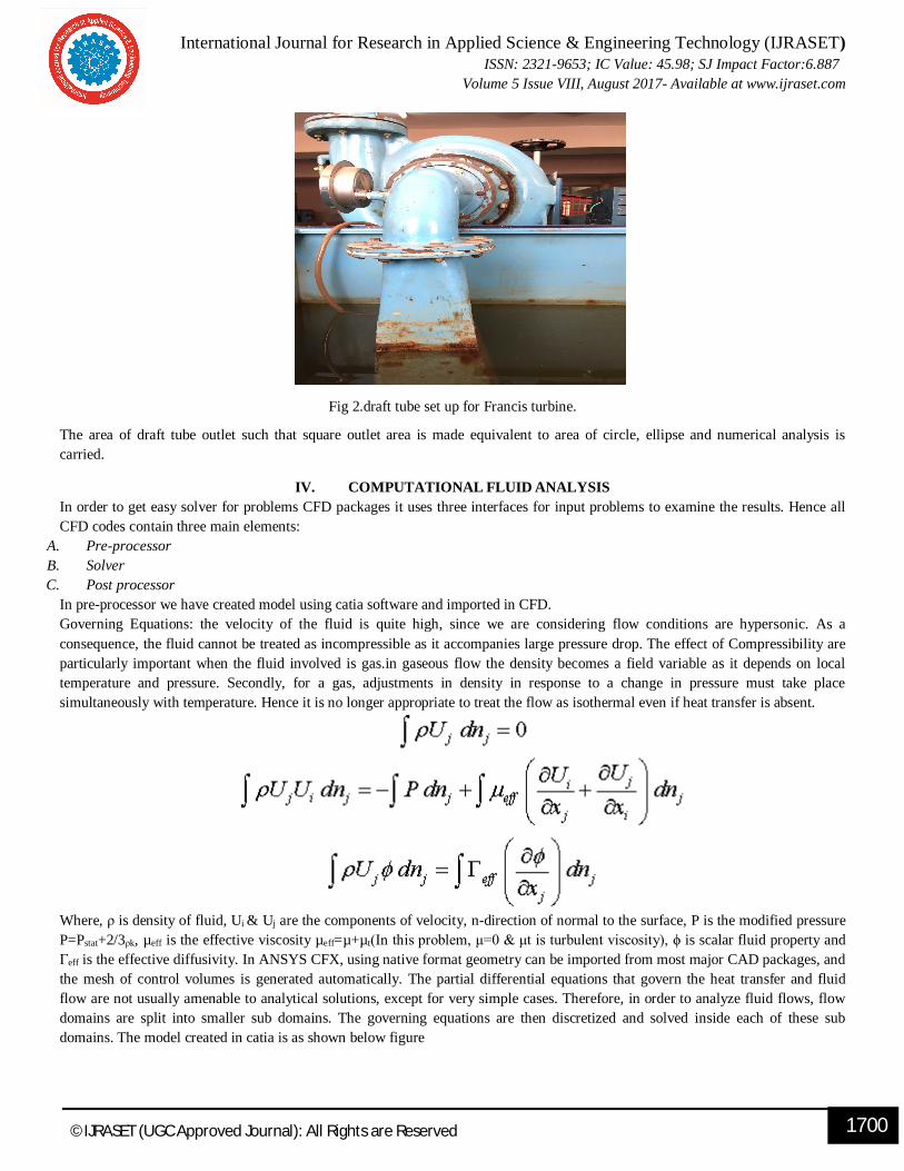
Fig 2.draft tube set up for Francis turbine.
The area of draft tube outlet such that square outlet area is made equivalent to area of circle, ellipse and numerical analysis is carried.
IV. COMPUTATIONAL FLUID ANALYSIS In order to get easy solver for problems CFD packages it uses three interfaces for input problems to examine the results. Hence all CFD codes contain three main elements:
A. Pre-processor B. Solver C. Post processor
In pre-processor we have created model using catia software and imported in CFD. Governing Equations: the velocity of the fluid is quite high, since we are considering flow conditions are hypersonic. As a consequence, the fluid cannot be treated as incompressible as it accompanies large pressure drop. The effect of Compressibility are particularly important when the fluid involved is gas.in gaseous flow the density becomes a field variable as it depends on local temperature and pressure. Secondly, for a gas, adjustments in density in response to a change in pressure must take place simultaneously with temperature. Hence it is no longer appropriate to treat the flow as isothermal even if heat transfer is absent.
Where, ρ is density of fluid, Ui & Uj are the components of velocity, n-direction of normal to the surface, P is the modified pressure P=Pstat+2/3ρk, µeff is the effective viscosity µeff=µ+µt(In this problem, μ=0 & μt is turbulent viscosity), ϕ is scalar fluid property and Гeff is the effective diffusivity. In ANSYS CFX, using native format geometry can be imported from most major CAD packages, and the mesh of control volumes is generated automatically. The partial differential equations that govern the heat transfer and fluid flow are not usually amenable to analytical solutions, except for very simple cases. Therefore, in order to analyze fluid flows, flow domains are split into smaller sub domains. The governing equations are then discretized and solved inside each of these sub domains. The model created in catia is as shown below figure

International Journal for Research in Applied Science & Engineering Technology (IJRASET) ISSN: 2321-9653; IC Value: 45.98; SJ Impact Factor:6.887
Volume 5 Issue VIII, August 2017- Available at www.ijraset.com
1701 ©IJRASET (UGC Approved Journal): All Rights are Reserved
Fig 3. Draft tube model created using catia
The different models of draft tubes are created by equating the area of the square outlet to ellipse and circle and numerical analysis is carried and comparison is made to get the optimized geometry of the draft tube.
V. RESULT AND DISCUSSION
Figures below show the variation of velocity stream line in different geometries of draft tube by varying the length from 700 to 1000 mm. Velocity streamline are obtained at the mid-portion of the draft tube.
Fig 4 square –square for L=700mm Fig 5 square-circle for L=700mm Fig6 square to ellipse L=700mm
Fig 7 square-square L-=1000mm Fig 8 square-ellipse L=1000mm

International Journal for Research in Applied Science & Engineering Technology (IJRASET) ISSN: 2321-9653; IC Value: 45.98; SJ Impact Factor:6.887
Volume 5 Issue VIII, August 2017- Available at www.ijraset.com
1702 ©IJRASET (UGC Approved Journal): All Rights are Reserved
The figure 4,5 & 6 represents the variation of velocity stream line in square,cicle and ellipse geometries of draft tube outlet respectively, and length of the draft tube considered is 700mm.Numerical study is carried and to get optimized shape the length of the draft is increased to 1000mm.fig 7 &8 represents the variation of velocity stream line in square and ellipse respectively for l=1000mm.The velocity of fluid at inlet equal to fluid velocity at outlet of the turbine is calculated by experimental data, since outlet area is kept constant according to continuity law we are going get the same velocity, but the velocity head converted to pressure head is calculated for different geometries and length of the draft tube is increased to 1000mm and corresponding conversion of velocity head into pressure head is calculated. Draft tube efficiency is calculated and comparison is made optimized geometry is selected. For length 700mm the outlet velocity is increased to 4m/s in all cases. The W/L ratio is varied and increased length of 1000mm is used for further study. The efficiency of draft tube is found and is increased for all cases of draft tube having increased length 1000mm, and for ellipse it is 98.36.
TABLE NO.1VARIATION EFFICIENCY WITH DIFFERENT SHAPES.
VI. CONCLUSION A. Square-ellipse length increased to 1000 mm is best suited. B. The efficiency of draft tube is 98.26% is obtained numerically by equating square outlet area to ellipse. C. Increase in length to dia of from 700mm to 1000mm shows significant improvement in draft tube efficiency hence the
length of draft tube corresponding to D/L to 0.32 is the optimum length of draft tube and ellipse is better geometry for draft tube outlet.
REFERENCES [1] Oliver kirschner 2nd IAHR International Meeting of the Workgroup on Cavitation and Dynamic Problems in Hydraulic Machinery and Systems Timisoara,
Romania(Scientific Bulletin of the “Politehnica” University of Timisoara Transactions on Mechanics Tom 52(66), Fascicola 2007 . [2] P. Rudolf “Connection between inlet velocity field and diffuser flow instability” Applied and Computational Mechanics Vol 3 (2009) pp177–184 . [3] Kai Kuppinger numerical analysis of draft tube flows and pasive ways to improve them .Institute of Fluid Mechanics and Hydraulic Machinery, University of
Stuttgart. [4] Dr. Ruchi Khare, Dr. Vishnu Prasad, Mitrasen Verma Dr. Ruchi Khare et al. “Hydraulic Turbine Draft Tube: Literature Review” International Journal of
Advances in Engineering, Science and Technology (IJAEST) [5] O. Kirschner, A. Ruprecht Velocity Measurement with PIV in a Straight Cone Draft Tube 3rd German - Romanian Workshop on Turbo machinery
Hydrodynamics, Timisoara, ROMANIA, May 10-12, 2007
Sl no Velocity at inlet m/s
Of draft tube Velocity at outlet of
draft tube
Efficiency of draft tube in %
1 SQUARE TO SQUARE 0.5356 89.29
2 SQUARE TO CIRCLE .5356 85.7
3 SQUARE TO ELLIPSE 0.5356
97.14
4 SQUARE TO SQUARE LENGTH INCREASED TO 1000mm
0.5356 93.86
5 SQUARE TO SQUARE
LENGTH INCREASED TO 1000mm
0.5356 98.26
