5. heat exchangers - wbuthelp.comof the hot stream for the parallel flow heat exchangers, while this...
TRANSCRIPT

5. Heat Exchangers 5.1 Introduction So far, we have studied the basic mechanisms for heat transfer. Various analytical and experimental correlations for the computation of the heat transfer were presented with numerous examples showing their application in engineering problems. In this chapter, we will use those correlations to describe the calculation procedure for heat transfer within widely used heat transfer devices, namely heat exchangers. Heat exchangers are thermal devices that transfer or exchange heat from one fluid stream to one or more others. It is a broad description to a vast range of hardware that operates in one of three ways:
1. By recuperation, or recovery, of heat from a hot stream to a cold stream; 2. by regeneration, as the hot and cold streams alternatively flow through a matrix; 3. by direct contact of one fluid stream with another.
The emphasis in this book will be on recuperative heat exchangers. These being by far the most common but this analysis can be extended to the other types. Examples of these types: Recuperation: Automotive radiators, oil coolers, power station condensers, economiser. Regenerative: Rotating matrix used to preheat exhaust gases, Stirling Cycle engine Direct contact: Cooling of hot metal sheet by a spray of water or air jet, cooling tower. In recuperative heat exchangers, mixing and contamination is prevented by solid walls. The dominant mechanisms of heat transfer are illustrated in Figure 5.1: Convection: A wall Conduction: Through wall Convection: wall B Figure 5-1 Mechanism of heat transfer in a heat exchanger
mywbut.com
1

Radiation will be present as well, but in most cases (excluding combustion) it is safe to assume that this is also negligible. There are at least two main objectives to the analysis of heat exchangers. The first is the design of a heat exchanger to fulfil a certain duty, providing geometric parameters. The second is the prediction of performance of a particular design working out inlet and outlet temperatures and heat flux. 5.2 Classification of Heat Exchangers Heat Exchangers are classified either by flow arrangement, by construction or by their degree of compactness. 5.2.1 Classification by flow arrangement In this classification, heat exchangers can be parallel flow, counter flow or cross flow as shown in Figure 5.2. In parallel flow heat exchangers, both flows run side by side, for example in concentric pipes. Counter flow heat exchangers are similar except the cold and hot streams go in opposite directions. Cross flow heat exchangers have the two flow stream normal to one another.
mywbut.com
2

The temperature distributions in a parallel and cross flow heat exchanger as a function of the coordinate along the heat exchanger are given in Figure 5.3.
It can be seen the exit temperature of the cold stream cannot by higher than the exit temperature of the hot stream for the parallel flow heat exchangers, while this is possible for counter flow heat exchangers. 5.2.2 Classification by construction A double pipe heat exchanger has a relatively poor performance resulting in a very large physical size to perform a given duty consequently; they are rarely used in practical applications in this form. In practice, other arrangements are possible which allow reduction in the physical size of the heat exchanger. Examples are the U-tube bundle and the shell and tube heat exchangers shown in Figure 5.4
Figure 5-2 Classification of heat exchangers by flow arrangement
Figure 0-3 Temperature distribution in parallel and counter flow heat exchangers
mywbut.com
3

A shell and tube is a development of a double pipe heat exchanger. This is a common form of construction, cheap and robust. However it is very heavy. Internal baffles are used to force the outer stream to cross the tubes, improving convective heat transfer.
U-tube
Shell and Tube
Figure 0-4 U-tube and shell-and-tube heat exchangers
mywbut.com
4

A typical example of cross flow heat exchangers is the plate-Plate-and-fin heat exchanger. In these types, flow channels are constructed from parallel plates separated by fins. Fins are used in both sides in gas to gas applications and on the gas side for gas to liquid applications such as automotive radiators. These can be either mixed or unmixed flow heat exchangers depending on whether the flow across the tubes is separated into various channels by plates or not. Typical cross flow heat exchangers are shown in Figure 5.5.
Figure 0-5 Examples of cross flow heat exchangers
mywbut.com
5
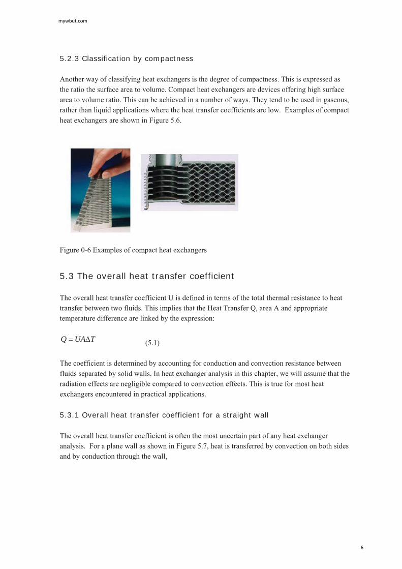
5.2.3 Classification by compactness Another way of classifying heat exchangers is the degree of compactness. This is expressed as the ratio the surface area to volume. Compact heat exchangers are devices offering high surface area to volume ratio. This can be achieved in a number of ways. They tend to be used in gaseous, rather than liquid applications where the heat transfer coefficients are low. Examples of compact heat exchangers are shown in Figure 5.6.
5.3 The overall heat transfer coefficient The overall heat transfer coefficient U is defined in terms of the total thermal resistance to heat transfer between two fluids. This implies that the Heat Transfer Q, area A and appropriate temperature difference are linked by the expression:
TUAQ (5.1) The coefficient is determined by accounting for conduction and convection resistance between fluids separated by solid walls. In heat exchanger analysis in this chapter, we will assume that the radiation effects are negligible compared to convection effects. This is true for most heat exchangers encountered in practical applications. 5.3.1 Overall heat transfer coefficient for a straight wall The overall heat transfer coefficient is often the most uncertain part of any heat exchanger analysis. For a plane wall as shown in Figure 5.7, heat is transferred by convection on both sides and by conduction through the wall,
Figure 0-6 Examples of compact heat exchangers
mywbut.com
6

)( 1TThAQq hh
(5.2)
)( 21 TTLkq
(5.3)
)( 2 cc TThq (5.4) Rearranging Equations 5.2 to 5.4,
hh h
qTT 1
(5.5)
LkqTT/21
(5.6)
cc h
qTT2
(5.7) Adding Equations 5.5 to 5.7 to eliminate wall temperatures gives:
chch hk
Lh
qTT 11
(5.8) which can be rearranged to give:
)(11 ch
ch
ch TTU
hkL
h
TTq
(5.9)
Figure 0-1: Heat flow across a solid wall with fluid either side
mywbut.com
7

Thus U is the overall heat transfer coefficient, referred to also as the U-value.
ch hkL
h
U11
1
(5.10) In the general case, the area on the hot and cold sides might not be equal, so the area needs to be taken into account. We then can define the overall heat transfer coefficient in that context as:
cw
h
cchh
hAR
hA
AUAUUA
)(1
)(1
1
(5.11) So if the area at the hot side is not the same as that on the cold side, then the associated heat transfer coefficient will not be the same.
mywbut.com
8
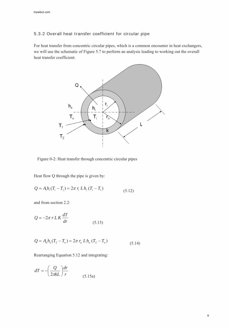
5.3.2 Overall heat transfer coefficient for circular pipe For heat transfer from concentric circular pipes, which is a common encounter in heat exchangers, we will use the schematic of Figure 5.7 to perform an analysis leading to working out the overall heat transfer coefficient.
Heat flow Q through the pipe is given by:
)(2)( 11 TThLrTThAQ iiiiii (5.12) and from section 2.2:
drdTKLrQ 2
(5.13)
)(2)( 22 oooooo TThLrTThAQ (5.14) Rearranging Equation 5.12 and integrating:
rdr
kLQdT
2 (5.15a)
Figure 0-2: Heat transfer through concentric circular pipes
mywbut.com
9

ln221
i
o
rr
kLQTT
(5.15b) Rearranging Equations and 5.12 and 5.14 gives:
iii Lhr
QTT21
(5.16)
ooo Lhr
QTT22
(5.17) Adding Equations 5.15b to 5.17 to eliminate the wall temperatures gives:
ooii
iooi rhrhk
rrL
QTT 11)/ln(2 (5.18)
Rearranging:
)(1ln
2 oio
oii
o
i
oo
oi
o
TTU
hrhr
rr
kr
TTLr
Q
(5.19)
Where oU is the overall heat transfer coefficient based on the outer area of the inner tube:
11lnoii
o
i
ooo hrh
rrr
krU
(5.20) Similarly we can work out an overall heat transfer coefficient based on the inner area of the inner tube:
11ln
ioo
i
i
oii hrh
rrr
krU
(5.21) Typical Values of overall heat transfer coefficients are given in Table 5.1 Table 0-1 Typical values of overall heat transfer coefficients
mywbut.com
10

Hot fluid Cold Fluid U (W/m2K) Water Water 1000-2500 Ammonia Water 1000-2500 Gases Water 10-250 Steam Water 1000-3500 Steam Gases 25-250
If 1io rr and the tubes are made from a good conductor, then the overall heat transfer coefficient reduces to:
Uhh
hhhh
UUio
io
oioi
111
(5.22)
if oi hh , then ohU
if io hh , then ihU So the heat transfer coefficient is controlled by the lower of heat transfer coefficients. To illustrate this assume a water to air heat exchanger, where the air side heat transfer coefficient is 40 W/m2K and the water side is 1000 W/m2K:
mywbut.com
11

KmWU 2/46.38100040100040
Consider two cases, one where the water side heat transfer coefficient is doubled and the other where the air side is doubled:
KmWU
KmWU
2
2
/07.74100080100080
/21.39200040200040
The former leads to a 2% change while the latter leads to 93% change. Example 5.1 Using the Dittus-Boelter correlation (Equation 3.52):
)( heating 4.0)( cooling 3.0
PrRe023.0 80
fs
fs
nDD
TTnTTn
Nu
Calculate the heat transfer coefficient for: 1 kg/s flow of water, density, 1000 kg/m3 at 300 K, k = 0.6 W/m K, Viscosity of 0.001 kg/ms, in a 50mm diameter tube, Pr=6 (Hot tube, cold fluid). For air, but with a velocity of fifteen times that if the water in part a. For air take the density 1.2 kg/m3, k = 0.02 W/m K and viscosity of 1.8x10⁻⁵ kg/ms, Pr = 0.7 Solution: (a)
VAm
smd
mA
mV /51.0
405.010
14
4
23
2
254641005.0
144Re 3dmVd
d
mywbut.com
12

1586.025464023.0 4080dNu
kdhNud
KmWd
kNuh d 2/189205.0
6.0158
(b)
smV /65.751.015
25500108.1
05.065.72.1Re 5d (Fifteen times velocity in a , but similar Re)
677.025500023.0 4080
dNu
KmWh 2/2705.0
02.067
(Similar values of Re but radically different h).
5.4 Analysis of Heat Exchangers There are two methods in use for the analysis of heat exchangers. The first is called the Log Mean Temperature Difference method (LMTD) and the second is called the Effectiveness – NTU method (Number of transfer Units) or simply the NTU method. In this book, we will explain and use the LMTD method. For the NTU method, the reader is referred to either Long (1999) or Incropera and DeWitt (2002). The heat transfer from one fluid stream to another can be written as:
mTUAQ (5.23)
Figure 0-3: Temperature distribution for a parallel flow heat exchanger
mywbut.com
13

:mT Some mean temperature difference, which will be defined later.
To determine mT we will make the following assumptions: No external losses from the heat exchanger Negligible conduction along the tube length; Changes in kinetic and potential energy are negligible h is constant along the length of the heat exchanger Specific heats are constant (not a function of temperature).
Consider a parallel flow heat exchanger with the temperature distribution as shown in Figure 5.9: The general relationship for the heat transfer from one fluid stream to the other is given by:
)( outFluidinFluidp TTcmQ (5.24)
)( HoHipHHH TTcmQ
mywbut.com
14

)( CiCopCCC TTcmQ
For the elemental section shown in Figure 5.9:
dQdQdQ CH (5.25)
HpHHH dTCmdQ (5.26)
CpCCC dTCmdQ (5.27) The overall change in temperature difference across the element is given by:
CH dTdTTd )( (5.28)
11)(pCCpHH CmCm
dQTd (5.29)
From Equation 5.1 we know that
TUdAdQTUAQ (5.30)
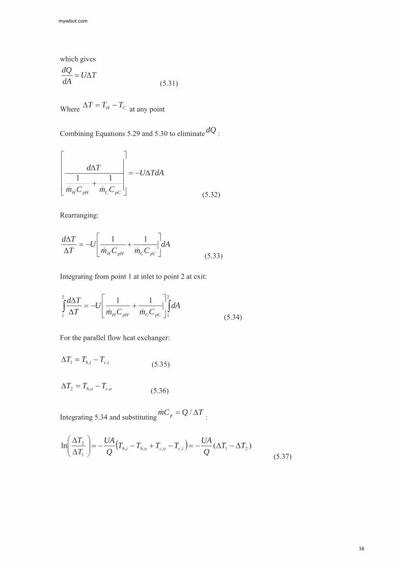
Figure 0-4: Analysis of heat flow through parallel flow heat exchanger
mywbut.com
15
which gives
TUdAdQ
(5.31)
Where CH TTT at any point
Combining Equations 5.29 and 5.30 to eliminate dQ :
TdAU
CmCm
Td
pCCpHH
11
(5.32) Rearranging:
dACmCm
UTTd
pCCpHH
11
(5.33) Integrating from point 1 at inlet to point 2 at exit:
2
1
2
1
11 dACmCm
UTTd
pCCpHH (5.34) For the parallel flow heat exchanger:
icih TTT ,,1 (5.35)
ocoh TTT ,,2 (5.36)
Integrating 5.34 and substituting TQCm p / :
)(ln 21,,,,1
2 TTQ
UATTTTQ
UATT
icocohih
(5.37)
mywbut.com
16
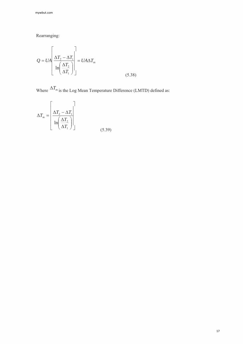
Rearranging:
mTUA
TT
TTUAQ
1
2
12
ln (5.38)
Where mT is the Log Mean Temperature Difference (LMTD) defined as:
1
2
12
lnTT
TTTm
(5.39)
mywbut.com
17

For a counter flow heat exchanger, with a temperature distribution as shown in Figure 5.10:
If we define:
ocih TTT ,,1 (5.40)
icoh TTT ,,2 (5.41) And we repeat the derivation; an identical expression is obtained for the LMTD as in Equations 5.38 and 5.39. However, care should be taken when defining the temperature difference in Equations 5.40 and 5.41 as opposed to those for parallel flow heat exchanger given in Equations 5.35 and 5.36. Equations 5.38 and 5.39 can also be extended to other types of heat exchangers such as cross flow or shell and tube using a correction factor which is a function of two other dimensionless factors which are in turn defined empirically as follows:
FTT cfmm 1 (5.42)
Where cfmT1 is the log mean temperature difference assuming counter flow heat exchanger and F is the correction factor defined as follows:
),( RPfF (5.43) Where P and R are empirical parameters defined as follows:
Figure 0-5: Counter flow heat exchanger terminology
mywbut.com
18

11
12
12
21 ,tTttP
ttTTR
(5.44) The temperatures in Equation 5.44 are defined, for example for a cross flow heat exchanger as shown in Figure 5.11.
R and P can be obtained from the empirical charts for various configurations. Figure 5.12 shows the correction factor for single pass cross flow heat exchanger with both streams unmixed. Correction factors for other configurations can be found in Incroperal and DeWitt (2002).
Figure 0-6 Inlet and outlet temperatures for a cross flow heat exchanger
Figure 0-7: Correction factor F for a single-pass cross flow heat exchanger with both streams unmixed
mywbut.com
19
Example 5.2 A concentric tube heat exchanger is used to cool lubricating oil for a large diesel engine. The inner tube is constructed of 2 mm wall thickness stainless steel, having k = 16 W/m K. The flow rate of cooling water through the inner tube (ri = 30mm) is 0.3 kg/s. The flow rate of oil through the tube (ro = 50mm) is 0.15 kg/s. Assume fully developed flow, if the oil cooler is to be used to cool oil from 90oC to 50oC using water available at 10oC, calculate: The length of the tube required for parallel flow; The length of the tube required for counterflow; The area required for a single pass cross-flow heat exchanger with both streams umixed, operating at the same temperatures and flow rates and with the same value of U as in a and b above. Solution: The water temperature at exit is unknown. This can be computed from the overall energy balance for oil and water.
mywbut.com
20
For oil: WTTCmQ ohihhph 12786)5090(213115.0)( ,,,
)( ,,, ociccpc TTCmQ
)10(41783.012786 ,ocT
For parallel flow:
CT o80)1090(1
CT o8.29)2.2050(2
CTTTTT o
lm 83.50)80/8.29ln(
808.29/ln 12
12
For counter flow:
CT o8.69)2.2090(1
CT o40)1050(2
CTTTTT o
lm 52.53)8.69/40ln(
8.6940/ln 12
12
For cross, flow, both streams are unmixed, in terms of the nomenclature for the cross flow:
CTTCTTCTtCTt ooc
oic
ooh
oih 2.20 ,10 ,50 ,90 ,2,1,2,1
5.0 255.011
12
12
21
tTttP
ttTTR
From Figure 5.12, 98.0F Therefore:
CFTT ocflmm 45.5298.052.53,
CT ooc 2.20,
mywbut.com
21

Area of tube:
lmTUAQ
lmTUQA
For parallel flow:
22.1183.509.21
12786 mA
mr
ALi
6103.02
2.112
For counter flow:
29.1052.539.21
12786 mA
mr
ALi
9.5703.02
9.102
For cross flow:
213.1145.529.21
12786 mA
Comment: The counter flow heat exchanger has the smallest area and thus can be considered more efficient. However, both parallel and counter flow are very long and could be impractical for engineering applications. The cross flow might provide the area required in a shorter length, however, a shell and tube heat exchanger might be superior to the other three arrangements. In the previous example, it was possible to work out the required information directly because three of the four inlet and outlet temperatures were known and the fourth could be computed from an energy balance. If only inlet temperatures were known, then this poses a difficulty to the design process. A method of overcoming this is illustrated in the following example:
mywbut.com
22

Example 5.3 The double pipe heat exchanger of Example 5.2 is to be used to cool 0.15kg/s of oil at 90oC using 0.3kg/s of seawater at 10oC. The area of the heat exchanger is 11.5m2 and the overall heat transfer coefficient is 21.9W/m2K. What are the exit states of oil and water from the heat exchanger? Solution To be able to calculate temperatures, an energy balance need to be performed. This requires knowledge of the overall heat transfer Q. This can be computed from the relation:
lmTUAQ
However, lmT is not known so an iterative procedure needs to be followed. The steps are:
Assume a value of ohT ,
Calculate ocT , from energy balance as in example 5.2
Calculate lmT and then Q
From Q and the capacity rate, compute ohT ,
mywbut.com
23
Compare ohT , with the initial value. If the two do not agree (say within Co5.0 repeat the
iteration with a new value of ohT , until convergence (usually taking the average between current and previous solutions improves the rate of convergence). So the sequence becomes:
Assume CT ooh 70,
)()( ,,,,,, ociccpcohihhph TTCmTTCm
CTCm
TTCmT o
iccp
ohihhphoc 1.1510
41783.07090213115.0)(
,,
,,,,
CT o80)1090(1
CT o9.24)1.1550(2
CT olm 66.66
)80/9.24ln(809.24
Evaluate Q:
WTUAQ lm 1678866.665.119.21
Calculate new ohT ,
)( ,,, ohihhph TTCmQ
CCmQTT o
hphihoh 5.37
213115.01678890
,,,
Comparing with assumed value, the difference is 32.5oC A reasonable choice for the 2nd iteration is the average value between the first assumption and the computed value, therefore, for the 2nd iteration, assume:
CT oh 7.53)5.3770(5.0,
mywbut.com
24

From which:
CT oc 24.19,
CTlm 09.50
WQ 13623
CT oh 38.47, The difference now is 6.3oC For third iteration, take:
CT oh 56.50)38.477.53(5.0, From which
CT oc 05.20,
CTlm 33.51
WQ 12356
CT oh 32.51, giving a difference of 0.7oC A fourth iteration is necessary to bring error within specified bound.
mywbut.com
25

5.5 Summary In this Chapter, we discussed the main classifications of heat exchangers. The chapter then focused on the analysis for recuperation type. Recuperation heat exchangers were classified based on three criteria. The first is based on flow arrangement, where heat exchangers are classified to parallel flow, counter flow and cross flow. The second criterion was based on construction. Of these, we mentioned double pipe, U-tube and shell and tube heat exchangers. A third classification is that based on compactness where heat exchangers are classified according to volume to surface area ratio. We then derived a formulation for the overall heat transfer coefficient for straight wall and circular pipe heat exchangers. The overall heat transfer coefficient takes into account the conductance in the two fluids and the metal separating them. The overall heat transfer coefficient U is defined such that the heat transfer is given by:
mTUAQ The final stage is to provide analysis of heat exchangers, were the Log Mean Temperature
Difference (LMTD) method was used. This led to the formulation for mT which can be used in the above equation to calculate the heat transfer in a heat exchanger.
mywbut.com
26