48v buck converter for automotive systems · 2020-01-17 · this reference design showcases a 48v...
TRANSCRIPT

MPQ2908 Reference Design 48V Buck converter for Automotive Systems

MPQ2908 Reference Design 48V Buck converter for Automotive Systems
MPQ2908 Reference Design MonolithicPower.com 1
1/17/2020 MPS Proprietary Information. Patent Protected. Unauthorized Photocopy and Duplication Prohibited. © 2020 MPS. All Rights Reserved.
Contents
1 Overview ........................................................................................................................................ 2
1.1 Description .................................................................................................................................. 2
1.2 Features .................................................................................................................................. 2
1.3 Applications ............................................................................................................................. 2
2 Reference Design ........................................................................................................................... 3
2.1 Block Diagram ......................................................................................................................... 3
2.2 Related Solutions .................................................................................................................... 3
2.3 System Specifications .............................................................................................................. 3
3 Design ............................................................................................................................................ 4
3.1 MPS Subsection ....................................................................... Error! Bookmark not defined.
3.2 Schematic ................................................................................................................................ 4
3.3 BOM ........................................................................................................................................ 5
3.4 PCB Layout ............................................................................................................................. 9
4 Test Results .................................................................................................................................. 11
4.1 Efficiency and Regulation ...................................................................................................... 11
4.2 Time Domain Waveforms ...................................................................................................... 12
4.3 Thermal Measurements ......................................................................................................... 14
4.4 EMC Measurements .............................................................................................................. 15
5 Start-Up ........................................................................................................................................ 16
5.1 Subsection ................................................................................ Error! Bookmark not defined.
6 Disclaimer ..................................................................................................................................... 17
MPQ2908 Reference Design 48V Buck converter for Automotive Systems
MPQ2908 Reference Design MonolithicPower.com 2
1/17/2020 MPS Proprietary Information. Patent Protected. Unauthorized Photocopy and Duplication Prohibited. © 2020 MPS. All Rights Reserved.
1 Overview
1.1 Description
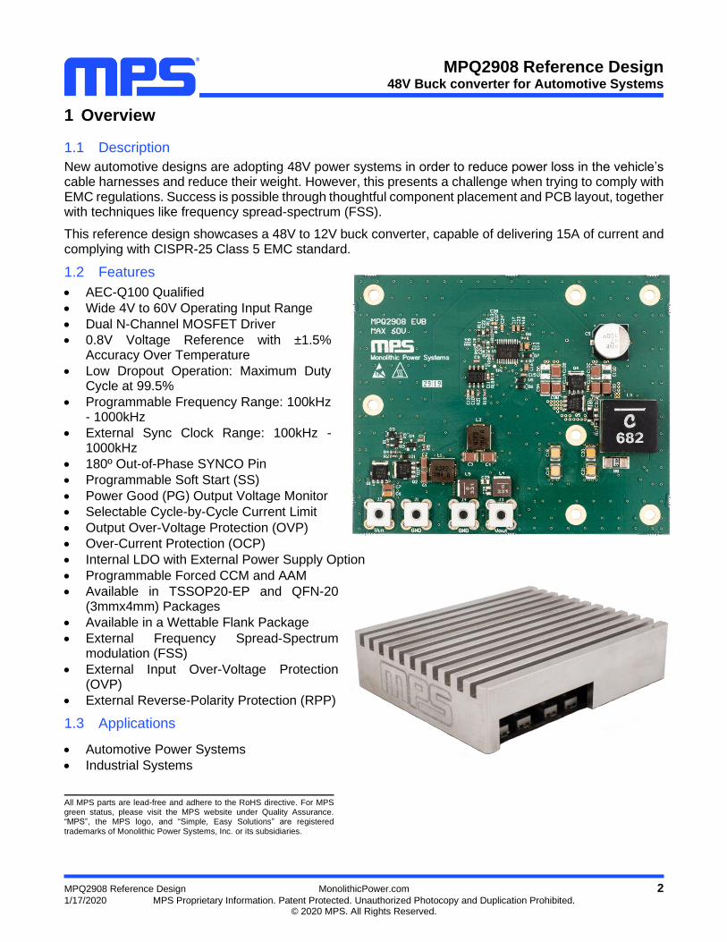
New automotive designs are adopting 48V power systems in order to reduce power loss in the vehicle’s cable harnesses and reduce their weight. However, this presents a challenge when trying to comply with EMC regulations. Success is possible through thoughtful component placement and PCB layout, together with techniques like frequency spread-spectrum (FSS).
This reference design showcases a 48V to 12V buck converter, capable of delivering 15A of current and complying with CISPR-25 Class 5 EMC standard.
1.2 Features
• AEC-Q100 Qualified
• Wide 4V to 60V Operating Input Range
• Dual N-Channel MOSFET Driver
• 0.8V Voltage Reference with ±1.5% Accuracy Over Temperature
• Low Dropout Operation: Maximum Duty Cycle at 99.5%
• Programmable Frequency Range: 100kHz - 1000kHz
• External Sync Clock Range: 100kHz - 1000kHz
• 180º Out-of-Phase SYNCO Pin
• Programmable Soft Start (SS)
• Power Good (PG) Output Voltage Monitor
• Selectable Cycle-by-Cycle Current Limit
• Output Over-Voltage Protection (OVP)
• Over-Current Protection (OCP)
• Internal LDO with External Power Supply Option
• Programmable Forced CCM and AAM
• Available in TSSOP20-EP and QFN-20 (3mmx4mm) Packages
• Available in a Wettable Flank Package
• External Frequency Spread-Spectrum modulation (FSS)
• External Input Over-Voltage Protection (OVP)
• External Reverse-Polarity Protection (RPP)
1.3 Applications
• Automotive Power Systems
• Industrial Systems
All MPS parts are lead-free and adhere to the RoHS directive. For MPS green status, please visit the MPS website under Quality Assurance. “MPS”, the MPS logo, and “Simple, Easy Solutions” are registered trademarks of Monolithic Power Systems, Inc. or its subsidiaries.

MPQ2908 Reference Design 48V Buck converter for Automotive Systems
MPQ2908 Reference Design MonolithicPower.com 3
1/17/2020 MPS Proprietary Information. Patent Protected. Unauthorized Photocopy and Duplication Prohibited. © 2020 MPS. All Rights Reserved.
2 Reference Design
2.1 Block Diagram
Buck converter with 48V nominal input, 12V 15A output capability, input EMI filter, RPP and OVP, FSS modulation.
Figure 1: Block diagram
2.2 Related Solutions
This reference design is based on the following MPS solutions:
Table 1: MPS Solutions
MPS Integrated Circuit Description
MPQ2908A 4V-60V Input, Current Mode, Synchronous, Step-Down Controller. AEC-Q100 Qualified
2.3 System Specifications
Table 2: System Specifications
Parameter Specification
Input voltage range 18VDC to 60VDC
Output voltage 12VDC
Maximum output current 15A (with 12V output)
Switching frequency 430kHz
Board form factor 94mmx78mmx12mm
Peak Efficiency 94.2%
12V output ripple 22mVp-p
MPQ2908 Reference Design 48V Buck converter for Automotive Systems
MPQ2908 Reference Design MonolithicPower.com 4
1/17/2020 MPS Proprietary Information. Patent Protected. Unauthorized Photocopy and Duplication Prohibited. © 2020 MPS. All Rights Reserved.
3 Design
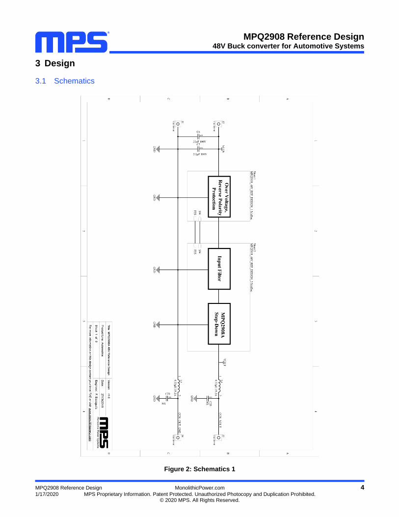
3.1 Schematics
Figure 2: Schematics 1

MPQ2908 Reference Design 48V Buck converter for Automotive Systems
MPQ2908 Reference Design MonolithicPower.com 5
1/17/2020 MPS Proprietary Information. Patent Protected. Unauthorized Photocopy and Duplication Prohibited. © 2020 MPS. All Rights Reserved.
Figure 3: Schematics 2

MPQ2908 Reference Design 48V Buck converter for Automotive Systems
MPQ2908 Reference Design MonolithicPower.com 6
1/17/2020 MPS Proprietary Information. Patent Protected. Unauthorized Photocopy and Duplication Prohibited. © 2020 MPS. All Rights Reserved.
Figure 4: Schematics 3

MPQ2908 Reference Design 48V Buck converter for Automotive Systems
MPQ2908 Reference Design MonolithicPower.com 7
1/17/2020 MPS Proprietary Information. Patent Protected. Unauthorized Photocopy and Duplication Prohibited. © 2020 MPS. All Rights Reserved.
3.2 BOM
Table 3: Bill Of Materials for the reference design
Designator Qty Value Package Manufacturer Part Number
C1, C2, C7 3 2.2µF 100V 1206 TDK CGA5L3X7S2A225K160AB
C3, C4, C9A, C9B, C9C, C9D, C10A, C10B
8 4.7µF 100V 1210 TDK C3225X7S2A475M200AB
C5 1 47µF 100V 10mm x 10mm
United Chemi-Con
EMVE101ADA470MJA0G
C6 1 22nF 100V 1206 KEMET C1206C223K1RECAUTO
C8, C11A, C11B, C14, C15
5 100nF 100V 0603 Murata GCJ188R72A104KA01D
C9 1 1µF 16V 0603 Murata GCM188R71C105KA64J
C10 1 6.8nF 16V 0603 Vishay Vitramon
VJ0603Y682KXJCW1BC
C10C, C10D 2 NS 1210 TDK C3225X7S2A475M200AB
C11, C12 2 100nF 16V 0603 KEMET C0603X104J4RECAUTO
C13 1 1µF 100V 0805 Murata GCM21BC72A105KE36L
C16 1 220nF 100V 0805 KEMET C0805C224K1RACTU
C17 1 4.7µF 16V 0603 Murata GRM188R61C475KAAJD
C18, C19, C20, C21
4 22µF 25V 1210 Murata GRM32ER61E226KE15L
C22 1 22pF 25V 0603 Kyocera AVX 06033A220JAT2A
C23 1 1µF 25V 0603 Yageo CC0603KRX5R8BB105
C24 1 10nF 16V 0603 KEMET C0603C103M3RACTU
C25, C29 2 NS 0805
C26, C27 2 NS 0603
C28 1 1nF 16V 0603 Yageo CC0603JRNPO8BN102
C31 1 NS 0805 Murata GCJ188R72A104KA01D
D1, D3, D5, D6
4 1N4148 SOD-323 Diodes 1N4148WSQ-7-F
D2 1 10V Zener SOD-523 Diodes BZT585B10T-7
D4 1 65V Zener SOT-23 ON Semiconductor
SZBZX84C62LT1G
D7 1 PMEG6010CEJ SOD-323 Nexperia PMEG6010CEJ,115
D8 1 RB168MM150TFTR SOD-123 Rohm RB168MM150TFTR
J1, J2, J3, J4 4 74650073R Wurth Electronics
74650073R
L1, L2 2 2.2µH 8A 20mΩ 7030 Eaton HCMA0703-2R2-R
L3 1 6.8µH 26A 4.17mΩ 1510 Coilcraft XAL1510-682MEB
L4, L5 2 0.33µH 19.2A 3.52mΩ 5030 Coilcraft XAL5030-331MEC
Q1, Q2 2 SQJA80EP PowerPAK-
SO-8L-4 Vishay SQJA80EP-T1_GE3
Q3 1 SBC846BLT1G SOT-23-3 ON Semiconductor
SBC846BLT1G

MPQ2908 Reference Design 48V Buck converter for Automotive Systems
MPQ2908 Reference Design MonolithicPower.com 8
1/17/2020 MPS Proprietary Information. Patent Protected. Unauthorized Photocopy and Duplication Prohibited. © 2020 MPS. All Rights Reserved.
Q4, Q5 2 SQJA82EP-T1_GE3 PowerPAK-
SO-8L-4 Vishay SQJA82EP-T1_GE3
R1, R5, R19 3 1kΩ 5% 0603 Yageo RC0603JR-071KL
R2, R6, R9 3 100Ω 5% 0603 Yageo RC0603JR-07100KL
R3, R4 2 20Ω 5% 0603 Yageo RC0603JR-0720KL
R7 1 2.2Ω 5% 0603 Panasonic ERJ-3GEYJ2R2V
R8 1 3mΩ 1% 2512 Yageo PA2512FKF7W0R003E
R10 1 45.3kΩ 1% 0603 Bourns CR0603-FX-4532ELF
R11 1 84.5kΩ 0.5% 0603 Panasonic ERJ-PB3D8452V
R12 1 6.04kΩ 1% 0603 Panasonic ERJ-3EKF6041V
R13 1 33kΩ 1% 0603 Panasonic ERJ-3EKF3302V
R14, R18 2 NS 0603 Yageo RC0603JR-070RL
R15, R16, R22
3 0Ω 5% 0603 Yageo RC0603JR-070RL
R17 1 10Ω 5% 0805 Panasonic ERJ-P06J101V
R20 1 NS 0603 Panasonic ERJ-3GEYJ103V
R21 1 11kΩ 5% 0603 Panasonic ERJ-3GEYJ113V
U1 1 MPQ2908A TSSOP-20
EP MPS MPQ2908AGF-AEC1
U2 1 TLC555QDRQ1 SOIC-8 Texas Instruments
TLC555QDRQ1
MPQ2908 Reference Design 48V Buck converter for Automotive Systems
MPQ2908 Reference Design MonolithicPower.com 9
1/17/2020 MPS Proprietary Information. Patent Protected. Unauthorized Photocopy and Duplication Prohibited. © 2020 MPS. All Rights Reserved.
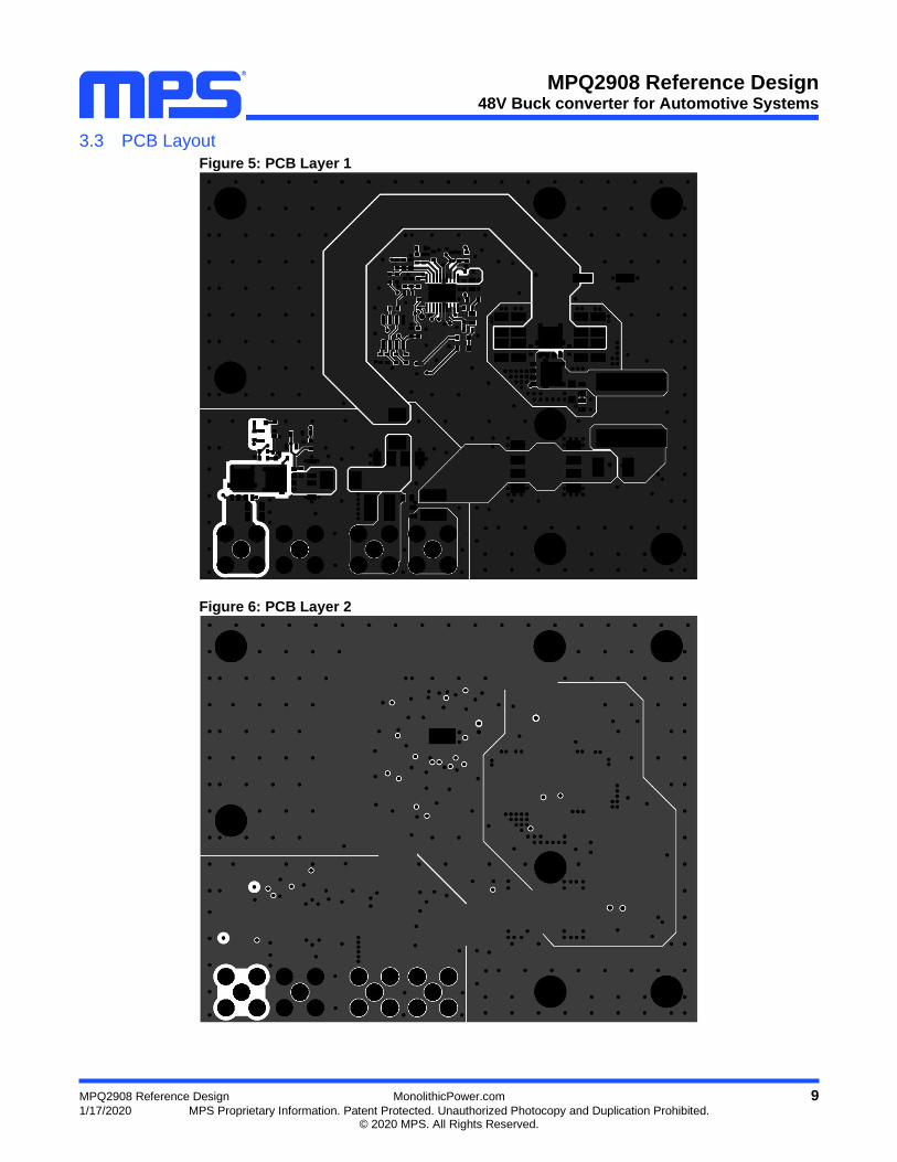
3.3 PCB Layout
Figure 5: PCB Layer 1
Figure 6: PCB Layer 2
MPQ2908 Reference Design 48V Buck converter for Automotive Systems
MPQ2908 Reference Design MonolithicPower.com 10
1/17/2020 MPS Proprietary Information. Patent Protected. Unauthorized Photocopy and Duplication Prohibited. © 2020 MPS. All Rights Reserved.
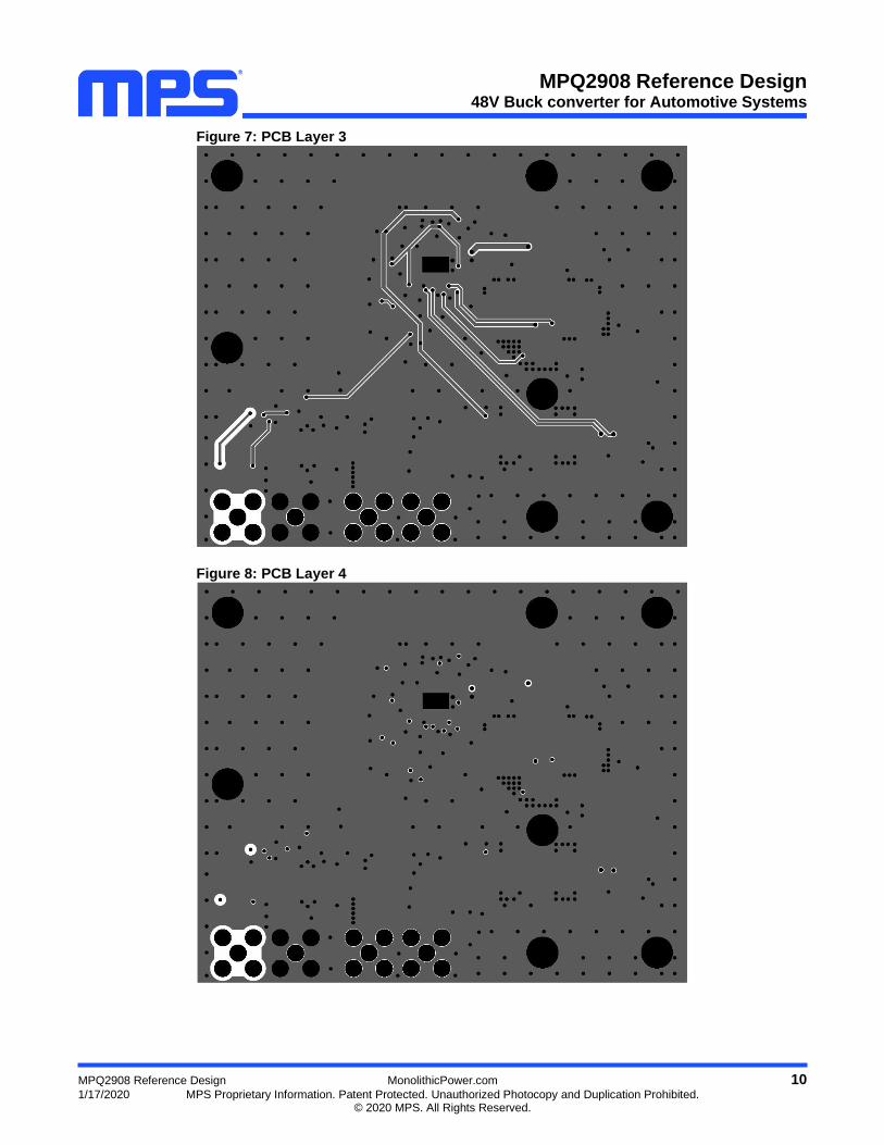
Figure 7: PCB Layer 3
Figure 8: PCB Layer 4

MPQ2908 Reference Design 48V Buck converter for Automotive Systems
MPQ2908 Reference Design MonolithicPower.com 11
1/17/2020 MPS Proprietary Information. Patent Protected. Unauthorized Photocopy and Duplication Prohibited. © 2020 MPS. All Rights Reserved.
4 Test Results
4.1 Efficiency and Regulation
VOUT = 12V, L = 6.8µH, FSW= 400kHz, CCM Mode, Cu Thickness = 35µm, TA = 25ºC Figure 9: Efficiency vs. Load Current With OVP and EMI filter
Figure 10: Load Regulation
Without OVP and EMI filter
Figure 11: Line Regulation
With OVP and EMI filter, measured at output connector
Figure 12: Line Regulation
With OVP and EMI filter, Measured at output capacitors
Figure 13: Load Regulation
VIN = 48V
IOUT=0A
IOUT=7A
IOUT=15A IOUT=0A
IOUT=7A
IOUT=15A

MPQ2908 Reference Design 48V Buck converter for Automotive Systems
MPQ2908 Reference Design MonolithicPower.com 12
1/17/2020 MPS Proprietary Information. Patent Protected. Unauthorized Photocopy and Duplication Prohibited. © 2020 MPS. All Rights Reserved.
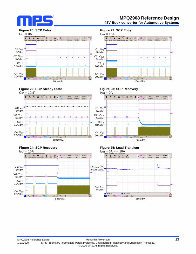
4.2 Time Domain Waveforms
VIN = 48V, VOUT = 12V, L = 6.8µH, TA = 25ºC, CCM Mode
Figure 14: Steady state IOUT = 0A
Figure 15: Steady State IOUT = 15A
Figure 16: Start-up through VIN IOUT = 0A
Figure 17: Start-up through VIN IOUT = 15A
Figure 18: Shutdown through VIN IOUT = 0A
Figure 19: Shutdown through VIN IOUT = 15A
C1: VOUT/AC 100mV/div.
C2: VSW 20V/div.
C3: IL 5A/div.
1µs/div. 1µs/div.
10ms/div.
C1: VIN 20V/div.
C2: VOUT 5V/div.
C3: IL 2A/div.
C4: VSW 20V/div.
5ms/div. 5ms/div.
20ms/div.
C1: VOUT/AC 100mV/div.
C2: VSW 20V/div.
C3: IL 5A/div.
C1: VIN 20V/div.
C2: VOUT 5V/div.
C3: IL 10A/div.
C4: VSW 20V/div.
C1: VIN 20V/div.
C2: VOUT 5V/div.
C3: IL 10A/div.
C4: VSW 20V/div.
C1: VIN 20V/div.
C2: VOUT 5V/div.
C3: IL 10A/div.
C4: VSW 20V/div.
MPQ2908 Reference Design 48V Buck converter for Automotive Systems
MPQ2908 Reference Design MonolithicPower.com 13
1/17/2020 MPS Proprietary Information. Patent Protected. Unauthorized Photocopy and Duplication Prohibited. © 2020 MPS. All Rights Reserved.
Figure 20: SCP Entry IOUT = 0A
Figure 21: SCP Entry IOUT = 15A
Figure 22: SCP Steady State CSS = 10nF
Figure 23: SCP Recovery IOUT = 0A
Figure 24: SCP Recovery IOUT = 15A
Figure 25: Load Transient IOUT = 5A <-> 10A
C1: VPG 5V/div.
C2: VOUT 5V/div.
C3: IL 10A/div.
C4: VSW 20V/div.
10ms/div.
C1: VPG 5V/div.
C2: VOUT 5V/div.
C3: IL 10A/div.
C4: VSW 20V/div.
C1: VSS 5V/div.
C2: VOUT 5V/div.
C3: IL 10A/div.
C4: VSW 20V/div.
5ms/div.
C1: VPG 5V/div.
C2: VOUT 5V/div.
C3: IL 10A/div.
C4: VSW 20V/div.
10ms/div.
5ms/div.
C1: VPG 5V/div.
C2: VOUT 5V/div.
C3: IL 10A/div.
C4: VSW 20V/div.
10ms/div.
5ms/div.
C1: VOUT/AC 500mV/div.
C2: IOUT 5A/div.

MPQ2908 Reference Design 48V Buck converter for Automotive Systems
MPQ2908 Reference Design MonolithicPower.com 14
1/17/2020 MPS Proprietary Information. Patent Protected. Unauthorized Photocopy and Duplication Prohibited. © 2020 MPS. All Rights Reserved.
Figure 26: Transient overvoltage test LV148 E48-02, VIN+ = 72V, tPEAK = 30ms, IOUT = 7A
Figure 27: Cold-crank test LV148 E48-10 VIN-= 24V, ttransient =1s, IOUT = 7A
4.3 Thermal Measurements
VIN = 48V, VOUT = 12V, L = 6.8µH, FSW = 400kHz TA = 25ºC, CCM Mode
Figure 28: Thermal Image
IOUT = 10A, without heatsink
Figure 29: MOSFET Case temperature: 123ºC
IOUT = 15A, Heatsink mounted, 2h runtime
200ms/div. 100ms/div.
C1: VBAT 10V/div.
C2: VIN 10V/div.
C3: VOUT 10V/div.
C4: VGS 10V/div. C1: VIN
20V/div.
C2: VOUT 5V/div.
C3: IL 5A/div.
C4: VSW 20V/div.

MPQ2908 Reference Design 48V Buck converter for Automotive Systems
MPQ2908 Reference Design MonolithicPower.com 15
1/17/2020 MPS Proprietary Information. Patent Protected. Unauthorized Photocopy and Duplication Prohibited. © 2020 MPS. All Rights Reserved.
4.4 EMC Measurements
VIN = 48V, VOUT = 12V, IOUT = 15A, L = 6.8μH, COUT=88μF, FSW=400kHz, TA = +25°C, FSS activated.
Figure 30: CISPR25 Class 5 Conducted Emissions
150kHz – 108MHz
MPQ2908 Reference Design 48V Buck converter for Automotive Systems
MPQ2908 Reference Design MonolithicPower.com 16
1/17/2020 MPS Proprietary Information. Patent Protected. Unauthorized Photocopy and Duplication Prohibited. © 2020 MPS. All Rights Reserved.
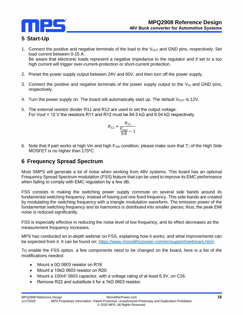
5 Start-Up
1. Connect the positive and negative terminals of the load to the VOUT and GND pins, respectively. Set load current between 0-15 A. Be aware that electronic loads represent a negative impedance to the regulator and if set to a too high current will trigger over-current-protection or short-current protection.
2. Preset the power supply output between 24V and 60V, and then turn off the power supply.
3. Connect the positive and negative terminals of the power supply output to the VIN and GND pins, respectively.
4. Turn the power supply on. The board will automatically start up. The default VOUT is 12V.
5. The external resistor divider R11 and R12 are used to set the output voltage. For Vout = 12 V the resistors R11 and R12 must be 84.5 kΩ and 6.04 kΩ respectively.
𝑅12 =𝑅11
𝑉𝑜𝑢𝑡0.8
− 1
6. Note that if part works at high Vin and high FSW condition, please make sure that TJ of the High Side
MOSFET is no higher than 175ºC.
6 Frequency Spread Spectrum
Most SMPS will generate a lot of noise when working from 48V systems. This board has an optional Frequency Spread Spectrum modulation (FSS) feature that can be used to improve its EMC performance when failing to comply with EMC regulation by a few dB. FSS consists in making the switching power supply commute on several side bands around its fundamental switching frequency, instead of having just one fixed frequency. This side-bands are created by modulating the switching frequency with a triangle modulation waveform. The emission power of the fundamental switching frequency and its harmonics is distributed into smaller pieces; thus, the peak EMI noise is reduced significantly. FSS is especially effective in reducing the noise level of low frequency, and its effect decreases as the
measurement frequency increases.
MPS has conducted an in-depth webinar on FSS, explaining how it works, and what improvements can
be expected from it. It can be found on: https://www.monolithicpower.com/en/support/webinars.html.
To enable the FSS option, a few components need to be changed on the board, here is a list of the
modifications needed:
• Mount a 0Ω 0603 resistor on R18.
• Mount a 10kΩ 0603 resistor on R20.
• Mount a 100nF 0603 capacitor, with a voltage rating of at least 6.3V, on C26.
• Remove R22 and substitute it for a 1kΩ 0603 resistor.

MPQ2908 Reference Design 48V Buck converter for Automotive Systems
MPQ2908 Reference Design MonolithicPower.com 17
1/17/2020 MPS Proprietary Information. Patent Protected. Unauthorized Photocopy and Duplication Prohibited. © 2020 MPS. All Rights Reserved.
To disable FSS, revert the former changes.
7 Disclaimer
Monolithic Power Systems (MPS) reserves the right to make changes to its products and to discontinue products without notice. The applications information, schematic diagrams, and other reference information included herein is provided as a design aid only and are therefore provided as-is. MPS makes no warranties with respect to this information and disclaims any implied warranties of merchantability or non-infringement of third-party intellectual property rights.
MPS cannot assume responsibility for use of any circuitry other than circuitry entirely embodied in an MPS product. No circuit patent licenses are implied.
Certain applications using semiconductor products may involve potential risks of death, personal injury, or severe property or environmental damage (“Critical Applications”).
MPS PRODUCTS ARE NOT DESIGNED, INTENDED, AUTHORIZED, OR WARRANTED TO BE SUITABLE FOR USE IN LIFE SUPPORT APPLICATIONS, DEVICES OR SYSTEMS, OR OTHER CRITICAL APPLICATIONS.
Inclusion of MPS products in critical applications is understood to be fully at the risk of the customer.
Questions concerning potential risk applications should be directed to MPS.
MPS semiconductors are typically used in power supplies in which high voltages are present during operation. High-voltage safety precautions should be observed in design and operation to minimize the chance of injury.