(4) well completion petronas
TRANSCRIPT

WELL COMPLETIONPROGRAM

The purpose of well completion is to provide communication between the reservoir and the surface production facilities.

TYPICAL WELL COMPLETION CONFIGURATION

Why well completion is so important ?
To effectively drain out the reservoir fluids to surface. Proper completion design is crucial in maximizing recovery.
To provide subsurface and surface flow control and safety. Several zones could be produced selectively or commingle it.
Isolate gas and water zones. To support wellbore and avoid excessive sand
production.

The well completion provides :
• Pressure control• A replaceable conduit for produced fluids• Selectivity of produced intervals• Simple well killing facilities• Potential for the exclusion of solids

ELEMENTS OFWELL COMPLETION
DESIGN
Res
ervo
ir C
onsi
dera
tion
Well Completion Design Consideration
2
1
3
4
5
67

1. Design Data RequirementWell Testing Data
• Production rate• Productivity Index, Skin and AOF• Basic Sediment and Water• Reservoir Pressure, Pr• Bottom Hole Flowing Pressure, Pwf
Temperature• Gas Oil Ratio (GOR), Gas Lliquid Ratio
(GLR) and Watercut (WC)• Type of fluid (oil, gas or water)• Degree API• Viscosity• Density• H2S, CO2 content• Fluid composition

1. Design Data Requirement ( cont..)
Reservoir Rock Properties
• Depth• Thickness• Porosity and Permeability• Capillary pressure• Rock strength (Brinell Hardness Number
and compressive strength)• Stresses• Young Modulus• Poissons ratio• Formation grain size (sieve analysis)

IPR with various Water Cut and GORsensitivity
10% WC
40% WC
> 60% WC
Increasing water cut
Pres
sure
, Psi
Production Rate, Q
High GOR scf/stb
GOR 400 scf/stb
GOR 100 scf/stb
Increasing GOR
Pres
sure
, Psi
Production Rate, Q
IPC
TPC
Notes: IPR – Inflow Performance Relationship; TPC – Tubing Performance Curve; GOR- Gas Oil Ratio
2. Design Process – Tubing Selection

IPR with THP and Pr Sensitivity
Increasing THP
THP 500 psi
THP 100 psi
THP 200
Pres
sure
, Psi
Production Rate, Q
Initial Pr
Depleted PrPr
essu
re, P
si
Production Rate, Q
Note: Pr – Reservoir Pressure

To as large as 9 5/8”
Tubing size ranges from 2 3/8”
7”
2 7/8”
3 1/2”
4”
4 1/2”
5 1/2”
Completion Tubing Sizes
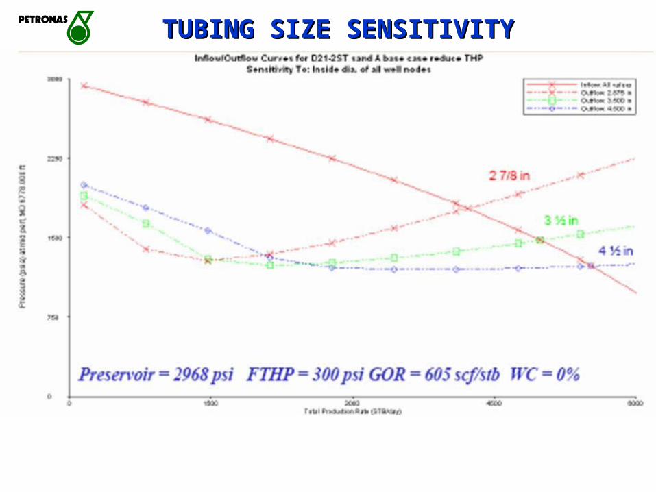
TUBING SIZE SENSITIVITYTUBING SIZE SENSITIVITY

Typical Casing Program
Conductor
Surfacecasing
Intermediatecasing
Production casing
Production liner

Production casing
Perforation
Tubing
Tubing hangerSCSSV
Landing/Seatingnipple
SSD
Wireline Entry Guide
1/4” control line
Gaslift mandrel(Side pocket mandrel)
Flow coupling
Dual packer
Blast jointTelescopic joint
No-go nipple Single packer
Completion Accessories

3. Special Study Requirement
• PVT • Core Analysis • Metallurgy
• Formation Water/Crude Analysis

• Production rate /Inflow performane
• Formation strength• Fluid type (corrosion, scale and
wax/asphaltene)• Reservoir permeability• Reservoir pressure • No. of reservoirs• Reservoir management
4. Reservoir Considerations

There are various types of well completion :5. Types of Well Completion
• Single string / selective single• Dual string• Gravelpack• slim well • monobore• horizontal• multilateral• twin well / triple well• Y Block completion• smart / intelligent well
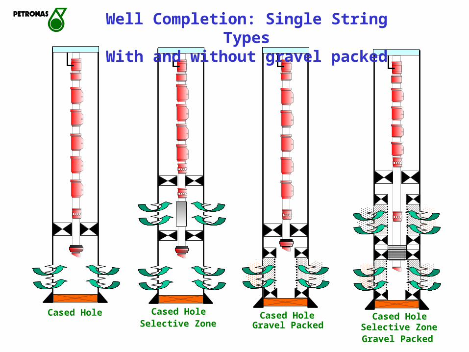
Selective Zone Selective ZoneGravel Packed
Gravel PackedCased Hole
Well Completion: Single String TypesWith and without gravel packed
Cased Hole Cased Hole Cased Hole
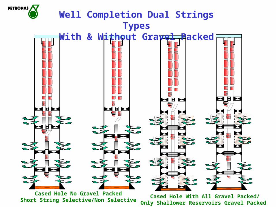
Well Completion Dual Strings TypesWith & Without Gravel Packed
Cased Hole No Gravel PackedShort String Selective/Non Selective Cased Hole With All Gravel Packed/
Only Shallower Reservoirs Gravel Packed

Slim Well
Drilling small hole sizes and completing with smaller casing scheme.
This will enable faster drilling with less casing tubular, cement and associated drilling materials hence lower cost.

Monobore Big bore Monobore
(e.g. 3 1/2” tubing with 3 1/2” liner) 4”-7” tubular

DUAL SLIMHOLE MONOBOREDUAL SLIMHOLE MONOBORE
7”
3-1/2”
9-5/8”
26”
7”
3-1/2”
23” hole
Flush Joint

Horizontal Well
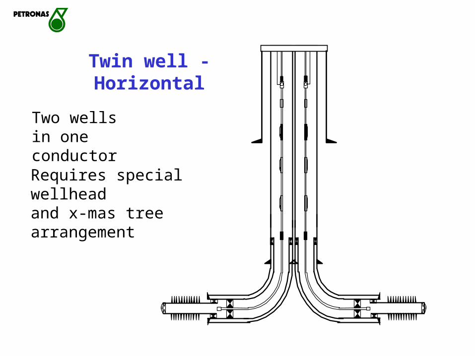
Twin well - Horizontal
Requires special wellheadand x-mas tree arrangement
Two wells in one conductor

TAML (Technology Advancement MultiLateral)
- 7" SC1AH Packer
- 4.00" Sealbore Extension
3.1/2" Float Shoe, FloatCollar and Landing Collar
Level 6 FORMationJunction 9.5/8"X7"X7"
LO W ERLATERAL
- Xover 4.1/2" 12.6 N Vam to 3.1/2" 9.2ppf New Vam
- Perforations inN-Series Sands
7" SC1AH Packer
- 4.00" Sealbore Extension
- Xover 4.1/2" 12.6 N Vam to 3.1/2" 9.2ppf New Vam
- Perforations inN-Series Sands
3.1/2" Float Shoe,Float Collar andLanding Collar
Size 51B Baker GTDual 3.1/2"X3.1/2" Dual Com pletion
Baker 9.5/8"X3.1/2"X3.1/2"Dual Com pletion M odule (DCM)
Size 80-40 Locator Seal Assem bly
Level 6

EW-117Level 6 Multilateral
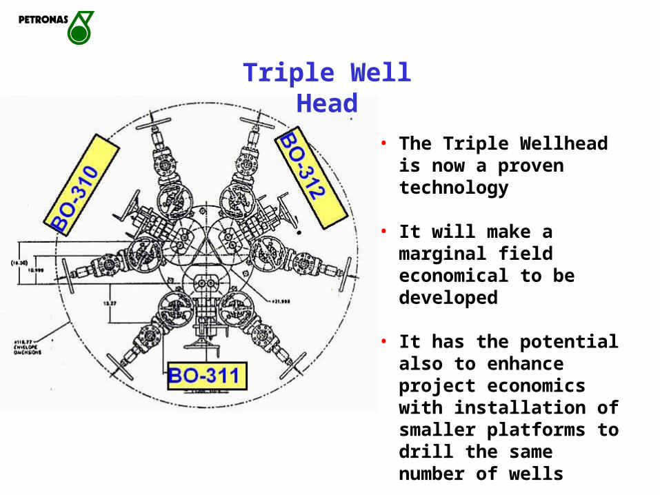
• The Triple Wellhead is now a proven technology
• It will make a marginal field economical to be developed
• It has the potential also to enhance project economics with installation of smaller platforms to drill the same number of wells
Triple Well Head

• Three wells drilled and completed from one shared conductor
• It provides 6 production strings
Triple well

Y Block Completion
Without Y Block, selectivity on short string is not possible (for gravelpack completion).
Typical Dual string Completion

Over the CouplingUmbilical Clamp
9 5/8" PES HF-1 Hydraulic Feed Through PackerNote all lines fed thru from Flatpack to respective tool
3 1/2" LV Ball Valve
3 1/2" PES Triple Gaugew External Port to LowerZone
3 1/2" CC-1 Sleeve
1/4" HydraulicTube terminatedfrom PDG to LV
3 1/2" SCSSV
PES 5 Line Flatpack
1/4" HydraulicTube from Gaugetransducer to LV
Valve
Advantages1-Shorter Manufacturing Time2-Significantly Lower Capex3-Two Less Electronic Connections
Dual Zone Completion with Triple P/TGauge Mandrel
SCSSV LinePT Gauge I WireControl Valve Hydraulic Line
PES Taper Lock Clamp(Stabilizes Flatpack End)
Hydraulic Splice Sub w Cover Sleeves(Acts as Hydraulic Termination Point & Take off for Hydraulic linesto surface, also a hydraulic tee for "common hydraulic line")
bottom CC-1 Sleeve)
SMART well with downhole inflow control and P/T gauges

SMART
2 SMART VALVES
• Under Balanced Drilling• SMART Commingling• Expandable Sand Screen
• Triple Gauge • Interval Control Valve• Lubricator Valve
150 ftah (50 ft tvd)8 1/2” hole, TD at 8113 ft (3890 ftss, 69 deg)
9 5/8” csg @ 7864 ftah (3630 ftss, 69 deg)
13 3/8” csg at 4000 ftah (2461 ftss, 69 deg)
26” conductor @ 600 ftah
7” Tbg L80 CS
3 1/2” Tbg L80 CS
3.1/2” SSD
3.1/2” Ball Valvewith P/T gauges
18 5/8” surface casing @ 1600 ftah (1445 ft.tvd, 37 deg)
H1
L1L2
SSD
• • • •
2 ICVLV
1
3
L
H
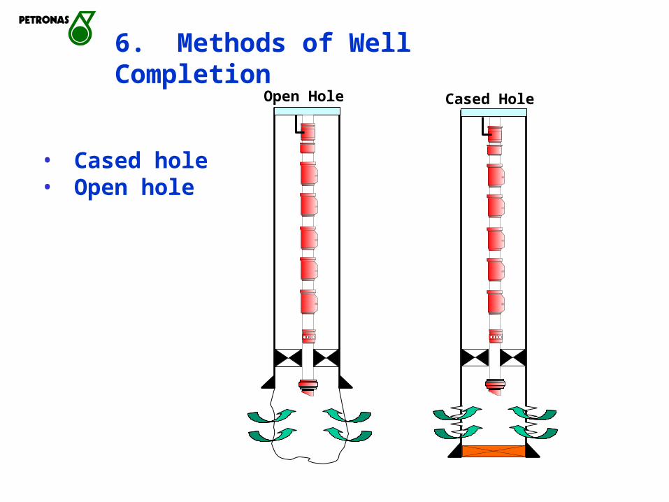
6. Methods of Well Completion
• Cased hole• Open hole
Open Hole Cased Hole

METHOD OF WELL COMPLETIONMETHOD OF WELL COMPLETION
Conventional Single/dual
Slimhole-monobore
26”
13-3/8”
9-5/8”
7”
24” / 20”x 13-3/8”
9-5/8”
3-1/2” tbg
2 x 7”
2 x 3-1/2”
SlimholeSingle
3-1/2”
7”
26”
TD = 5450-8000 ft
4-1/2”

Sequence of Completion Operations :
• Well cleanout• Perforate• Kill well • (Sand exclusion - if required)• Run and set completion string• Install X-mas tree• Flowline Tie-in • Unloading well• Handover to production

reservoir
reservoir
reservoir
reservoir
Well Preparation And Cleaning Clean Out
Assembly
Bit and Scraper
+Cleanout
Fluid

reservoir
reservoir
reservoir
reservoir
Well PerforatingPerforating
gunAssembly
reservoir
reservoir
reservoir
reservoir
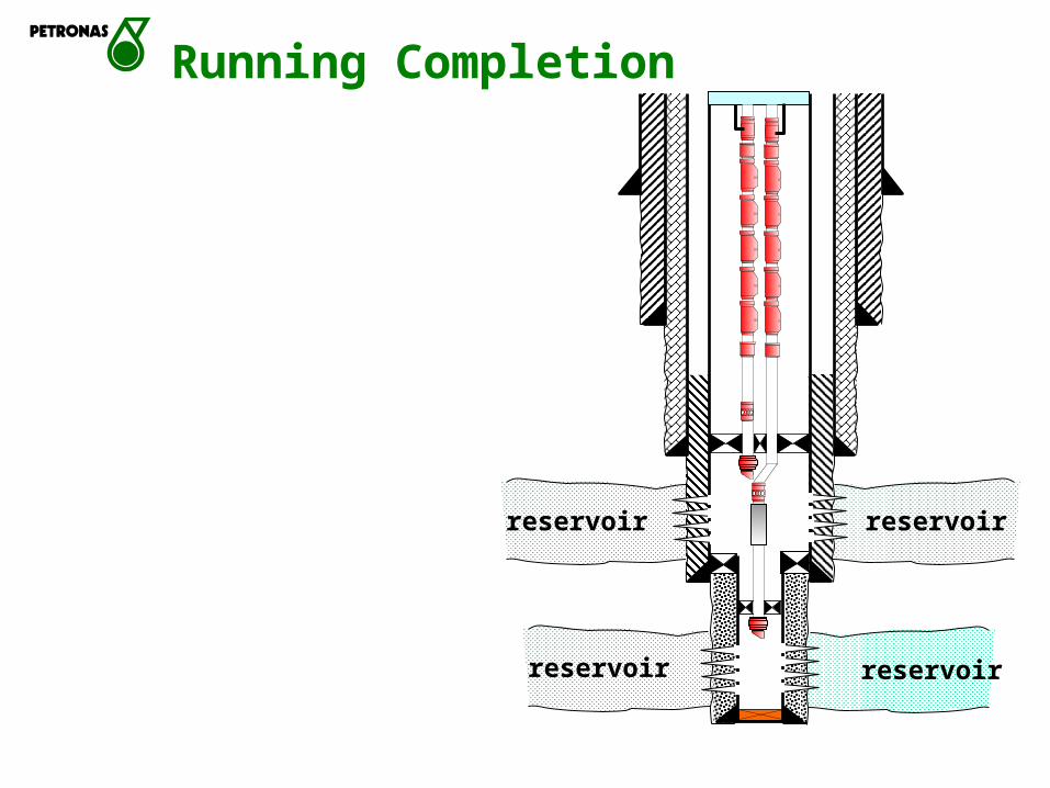
Running Completion

Install Christmas Tree
well

Production Flow Line Tie-In
Production header
ToProduction system
well

reservoir
reservoir
reservoir
reservoir
Unloading Well and Handover To Production Operations

• Safety• Simplicity/Reliability• Well Surveillance/Monitoring Requirement • Tubing Stress and Movement• Future Slick/E-line Intervention Technology• Future Work-over and Abandonment.
7. Mechanical Considerations

There are different ways of completing wells with different types of artificial lift
Types of artificial lift :• Gas lift • Sucker rod (Bean Pump)• Progressing Cavity Pump (PCP)• Electrical Submersible Pump (ESP)• Subsurface Hydraulic Jet Pump (SHJP)• Plunger Lift

Artificial lift – Gaslifting Well
GAS LIFT WELL
Injectiongas
Produced fluid Gas Sold or Flared
SEPARATOR
Oil & Water out
GAS SOURCEWELL
GAS LIFT WELL
Injectiongas
Produced fluid Gas Sold or Flared
SEPARATOR
Oil & Water out
GAS SOURCEWELL

Gaslift SystemGaslift System
Side Pocket Mandrel with Gas-Lift ValveGas-Lift Completion—SPMs
and Retrievable Valves
Artificial LiftArtificial Lift

Sucker rod (Bean Pump)
Artificial LiftArtificial Lift

Artificial LiftArtificial LiftSucker Rod Pump (SRP)Sucker Rod Pump (SRP)

Progressing Cavity Pump (PCP)
Artificial LiftArtificial Lift

Artificial LiftArtificial LiftProgressive Cavity Pump (PCP)Progressive Cavity Pump (PCP)
PCP Down Hole Equipment PCP Surface Facilities

Artificial LiftArtificial LiftProgressive Cavity Pump (PCP)Progressive Cavity Pump (PCP)

Artificial LiftArtificial LiftElectrical Submersible Pump (ESP)Electrical Submersible Pump (ESP)

Electrical Submersible Pump (ESP)Artificial LiftArtificial Lift

Artificial LiftArtificial LiftHydraulic Jet Pump (HJP)Hydraulic Jet Pump (HJP)

Artificial LiftArtificial Lift
Hydraulic Jet Pump (HJP)Hydraulic Jet Pump (HJP)

Plunger Lift
Artificial LiftArtificial Lift

THANK YOU

PCSB's well completion review• Most of PCSB's wells are cased hole either
single or dual completion. However, there are a few wells completed opened hole (slotted liner).
• Tubing size used range from 2-3/8" to 5-1/2 OD.
• PCSB has completed horizontal wells, multilateral wells, wells with gravel packing completion, slim well and one twin well.
• Completion with 1 packer to 6 packers, completing from 1 to 5 zones in a single wellbore.