4 trumbo rd limited concrete spalling repairs
TRANSCRIPT
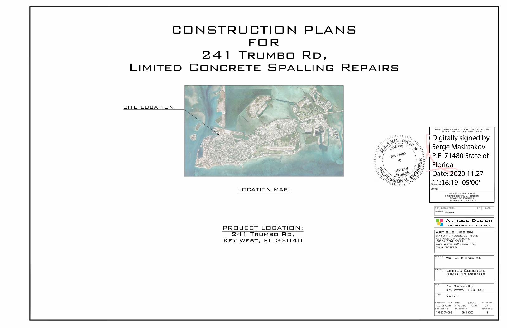
location map:
DATE:DESCRIPTION:REV: BY:
REVISION: PROJECT NO: DRAWING NO:
DRAWN: DATE: CHECKED:
TITLE:
SCALE AT 11x17:
CLIENT:
SITE:
STATUS:
PROJECT:
Artibus Design3710 N. Roosevelt BlvdKey West, FL 33040(305) 304-3512www.ArtibusDesign.comCA # 30835
Serge MashtakovProfessional Engineer
State of FloridaLicense No 71480
Signature:
Date:
this drawing is not valid without thesignature and original seal
William P Horn PA
Limited ConcreteSpalling Repairs
241 Trumbo RdKey West, FL 33040
Cover
Final
AS SHOWN 11/27/20 SAM SAM
1907-09 G-100 1
site location
CONSTRUCTION PLANSFOR
241 Trumbo Rd,Limited Concrete Spalling Repairs
PROJECT LOCATION:241 Trumbo Rd,
Key West, FL 33040

General Requirements:1. Prior to starting any work the Contractor shall review these plans and site
conditions and notify the Engineer if any discrepancies are discovered.2. The Engineer is not responsible for the supervision of the Contractor nor his
employees during the construction. It is the Contractor’s responsibility toprovide means and establish methods of the construction to meet requirements ofall applicable codes, industry standards and requirements of these plans.
3. Quality of the work shall meet or exceed industry standard practices.4. Any deviations from these plans shall be reviewed and approved by the Engineer.
Design Data:1. Applicable Building Code: FBC Existing Building 6th Edition (2017)2. Applicable Design Loads: per ASCI/SEI 7-10
Floor Live Load: 100 psfRoof Live Load: 20 psf (300 lb conc.)Basic Wind Speed: 180 MPHExposure: DStructural Category: II
Flood Zone: AE9
All pressures shown are based on ASD Design,with a Load Factor of 0.6
3.ASCE 24-14 FLOOD RESISTANT DESIGN AND CONSTRUCTION
Soils and Foundations:
Presumptive load-bearing values of foundation materials are used in lieu of acomplete geotechnical exploration.
Foundations shall be placed on a "Sedimentary and foliated rock" with an allowableload bearing pressure of 3,000 psf. Notify the Engineer if soil conditions aredifferent.
1. All foundations, slabs and footers shall be placed on stabilized undisturbedsubgrade soil.
2. Minimum foundation depth shall be 24” unless otherwise is specified on the plans.If over-excavated - fill shall not be placed back into the trench unless approvedby the Engineer.
3. Fill under the foundations shall be used only if approved by the Engineer. Cleanfill material shall be placed in 6”-8” layers and compacted to 98% density usingthe Modified Proctor Test.
4. Fill material shall be clean granular sand or limerock mix without any organicmaterials, clay, muck and rocks larger than 4”. Backfill shall not contain anywood or cellulose debris.
Augercast Piles1. Augercast piles shall be 16” diameter with minimum embedment of 3ft into the cap
rock unless otherwise shown on the plans.2. Concrete for piles shall have a min. compressive strength of 5000 psi.
Water/Cement ratio shall not exceed W/C=0.40.3. Reinforcement shall be four (4) #5 rebar vertically with #3 stirrups at 12” o.c.
Contractor shall use plastic chars or centralizers to provide a 3” cover on allsides of the reinforcement.
Concrete:1. Applicable Code ACI 318 latest edition and ACI 301.2. All concrete elements shall have a min. compressive strength of 4000 psi unless
otherwise is shown on the plans. Water/Cement ratio shall not exceed W/C=0.40.3. All cast-in-place concrete shall be cured and protected from overdrying per ACI
305R-10 "Hot Weather Concreting".4. All exposed edges shall have 1/2" chamfers.5. No cold joints are allowed unless otherwise approved by the Engineer.6. TESTING: All Field and Laboratory Testing shall be performed by an independent
specialized company. The contractor is responsible for all scheduling,coordination and cost of the testing company.
Three (3) samples shall be taken and tested each time.Minimum Sampling Frequency:a) Each day of concreting for every concrete mix;b) Every 50 cubic yards;c) Every 2000 sq.ft. of slab area.
All testing shall be per latest ACI and ASTM requirements.Laboratory shall supply three (3) original signed&sealed report results to the
Engineer.
7. Cast-in-place and precast member erection tolerances shall be as specified in thetable 8.2.2 or in section 8.3 of "PCI design handbook/Sixth edition".
Reinforcement:1. All rebar shall be deformed carbon-steel ASTM A615/A615M-13 Grade 60
unless otherwise specified on the plans.2. All requirements for placement, cover, tolerances, etc. Shall be per ACI 318-11.3. All hooks and bends shall be factory made unless field bends are approved by
the Engineer.4. Only PLASTIC CHAIRS and CENTRALIZERS shall be used for rebar support.
Aluminum Components:
1. Type 6061-T6 aluminum.2. MIG weld all joints w/ continuous 1/8" weld. Use 5356 filler wire alloy.3. All aluminum in contact with concrete, pt wood, dissimilar metals and
other corrosive materials shall coated with coal-tar epoxy or protected byother Engineer approved method.
Hardware:1. Hardware shall be 316 Stainless Steel or better, unless otherwise specified.
Structural Lumber:1. All wood members shall meet or exceed requirements specified in “ANSI/AF&PA
National Design Specification (NDS) for Wood Construction” and all referencedstandards.
2. All wood members shall be Pressure Treated Souther Pine No2 or Greater kilndried as specified in the Standards, unless otherwise specified.
3. All wood members exposed to exterior, in direct contact with concrete or steelshall be Pressure-Treated (PT) UC3B grade per AWPA Standards.
4. All field cuts in pt lumber shall be treated on site.5. Nailing shall be in accordance with FBC 6th Edition (2017). Nails and other
fasteners for PT wood shall be Stainless Steel or ACQ Approved treated.6.Sheathing shall be 19/32” CDX Plywood Sheathing Grade, unless otherwise is
specified on the plans. Use 8d ring-shank nails with spacing of 4” o.c. on alledges and 6” o.c. in the field.
Structural Steel:
1. Structural steel components shall be as described in "Specifications forStructural Steel Buildings" AISC 2005 or later edition.
2. HSS shapes (structural tubing) shall be ASTM A500 (Fy=46 ksi).3. Steel plates, flanges and miscellaneous elements shall be ASTM A36 (Fy=36 ksi)
unless noted otherwise on the plans.4. W-shapes, C-shapes and other formed steel shall be ASTM A992 (Fy=50 ksi).5. All welding shall be in conformance with the latest specifications AWS
D1.1/D1.1M:2010, Structural Welding Code - Steel.
Structural Steel Coating:
1. All surfaces shall be abrasive blast cleaned to near-white metal (per SSPC-SP10)Exposed Steel:2. All surfaces shall be primed with Polyamide Epoxy - one coat (8.0 mils DFT).3. Apply Sealant at all locations where steel is welded, lapped, etc. Sealant
material shall be compatible with the painting system.4. Top layer shall be two (2) coat Polyurethane (3.0 mils DFT each).5. Top paint shall be UV resistant or have a UV resistant coating.6. Colors shall match existing or to be selected by the owner.Non-Exposed Steel (Interior):7. 2 coats of "Sumter Coatings" Universal Primer (6.0 mils DFT) or Approved Equal.
Reinforced Masonry (CMU):
1. All Masonry shall be reinforced concrete masonry unit in accordance withthe latest edition of ACI 530/ASCE 5/TMS 402.
2. Install all blocks in running bond.3. Minimum masonry block (ASTM C90) strength shall (F'm) be 2000 psi.4. Type "S" mortar (ASTM C270) shall be used using 3/8" full bedding
reinforced w/ 9 gage 304SS ladder wire every 2nd row.5. Filled cells shall be reinforced with #5 rebar @ 24" o.c. (unless otherwise
is specified on the plans).6. Grout shall be pea rock pump mix (ASTM C476) with a minimum compressive
strength of 4000 psi (28 day) (ASTM C1019). Targeted slump shall be8"-11".
6. Each grouted cell shall have cleanout openings at the bottom. Thereshall be no loose mortar or other debris in the bottom of the cell. Useblast pressure washing for surface preparation.
CONCRETE REPAIRS:
1. REMOVE ALL LOOSE AND UNSOUND CONCRETE.2. EXPOSE ALL CORRODED REBAR FROM ALL SIDES (1.5" AROUND).3. CLEAN ALL EXPOSED REBAR BY MECHANICAL MEANS TO NEAR-WHITE CONDITION.4. PRESSURE WASH ALL CONCRETE AND REINFORCEMENT WITH POTABLE WATER.5. PRIME EXISTING REINFORCEMENT W/ "SIKA ARMATEC 110 EPOCEM" OR APPROVED
EQUAL. FOLLOW MANUFACTURER INSTRUCTIONS FOR SURFACE PREPARATION,APPLICATION AND CURING.
6. ALL REBAR WITH LOSS OF SECTION OVER 20% SHALL BE DUPLICATED WITH NEWREBAR OF EQUAL SIZE.
7. MINIMUM CONCRETE COVER SHALL BE 1.5" UNLESS OTHERWISE IS APPROVED BYTHE ENGINEER.
8. INSTALL SACRIFICIAL ANODES "VECTOR GALVASHIELD XPT" (OR APPROVEDEQUAL) AS SHOWN ON THE DIAGRAMS.
9. FOR SMALL PATCH REPAIRS (DEPTH UP TO 4", AREA UP TO 10 FT2) USE"SIKACRETE 211 SCC PLUS" REPAIR MORTAR.STRICTLY FOLLOW MANUFACTURER INSTRUCTIONS FOR SURFACE PREPARATION,APPLICATION AND CURING.
9A. FOR LARGE REPAIRS (FULL DEPTH SLAB, BEAM OR COLUMNREPAIR/REPLACEMENT) USE 4000 PSI CONCRETE MIX WITH W/C RATIO 0.4 MAX.WITH HIGH RANGE PLASTESIZER AND RUST INHIBITING ADMIXTURES.
10. FOR OVERHEAD REPAIR APPLICATION WITHOUT FORMING (SMALL DEPTH SLABAND BEAM REPAIRS) USE "SIKAQUICK® VOH" TROWEL GRADE REPAIR MORTARS.STRICTLY FOLLOW MANUFACTURER INSTRUCTIONS FOR SURFACE PREPARATION,APPLICATION AND CURING.
11. THE CONTRACTOR IS RESPONSIBLE FOR ANY SHORING/RESHORING ANDTEMPORARY SUPPORTS OF ALL STRUCTURAL ELEMENTS DURING THE REPAIR ANDTHROUGH THE CONCRETE CURING PERIOD.
! MOIST CURING FOR MINIMUM OF 4 DAYS IS REQUIRED. FOLLOW HOT WEATHERCONCRETING GUIDELINES.
! USE SIKA SET-XP ADHESIVE FOR ALL DOWELS AND REBAR EMBEDDED INTOEXISTING CONCRETE
DATE:DESCRIPTION:REV: BY:
REVISION: PROJECT NO: DRAWING NO:
DRAWN: DATE: CHECKED:
TITLE:
SCALE AT 11x17:
CLIENT:
SITE:
STATUS:
PROJECT:
Artibus Design3710 N. Roosevelt BlvdKey West, FL 33040(305) 304-3512www.ArtibusDesign.comCA # 30835
Serge MashtakovProfessional Engineer
State of FloridaLicense No 71480
Signature:
Date:
this drawing is not valid without thesignature and original seal
William P Horn PA
Limited ConcreteSpalling Repairs
241 Trumbo RdKey West, FL 33040
Notes
Final
AS SHOWN 11/27/20 SAM SAM
1907-09 G-101 1

WORK ZONE
SITE MAPSCALE: NTS
DETAIL
1TIE
-CO
LU
MN
REPAIR
DETAIL
2TIE
-CO
LU
MN
REPAIR
WALL VIEWPHOTOSCALE: NTS
PROTECT OR RELOCATEALL PLUMBING AND
MECHANICAL EQUIPMENTFOR DURATION OF
CONSTRUCTION ACTIVITIES
AFTER ALL REPAIRS ARE COMPLETE ANDCONCRETE IS CURED RESTORE MATCHINGCEMENT STUCCO, PRIME AND PAINTEXTERIOR WALL SURFACES AND RESTOREANY INTERIOR INSULATION AND FINISHESTO MATCH EXISTIGN CONDITIONS
DATE:DESCRIPTION:REV: BY:
REVISION: PROJECT NO: DRAWING NO:
DRAWN: DATE: CHECKED:
TITLE:
SCALE AT 11x17:
CLIENT:
SITE:
STATUS:
PROJECT:
Artibus Design3710 N. Roosevelt BlvdKey West, FL 33040(305) 304-3512www.ArtibusDesign.comCA # 30835
Serge MashtakovProfessional Engineer
State of FloridaLicense No 71480
Signature:
Date:
this drawing is not valid without thesignature and original seal
William P Horn PA
Limited ConcreteSpalling Repairs
241 Trumbo RdKey West, FL 33040
Site MapWork Zone
Final
AS SHOWN 11/27/20 SAM SAM
1907-09 S-101 1

TYPICAL TIE-COLUMN REPAIR ELEVATION VIEWSCALE:NTS
EXISTING ROOFTIE-BEAM TO REMAIN
EXTEND REPLACEMENT OFTHE CONCRETE COLUMN
6" BELOW EXISTING GRADEBEAM SURFACE
EXISTINGFOUNDATION
EPOXY DOWEL (4) #6 REBAREMBEDMENT 12" MIN.
EXISTING FIRST FLOORTIE-BEAM TO REMAIN(NOTIFY ENGINEER IF
DAMAGED
36" MIN. LAP INCOLUMN CAGE
36" MIN. LAP INCOLUMN CAGE
± 3
0-0
"FIE
LD
VER
IFY
2" MIN. COVER
±16"
FIELD VERIFY ALL DIMENSIONS.MATCH NEW COLUMN WIDTH
W/ EXISTING COLUMN WIDTH
6"
12
"
SAW CUT IN CLEANSTRAIGHT LINES
ADD "VECTOR GALVASHIELD XPT" ANODESTO EXISTING REINFORCEMENT
CONCRETE REPAIR/REPLACEMENT(SEE PLAN VIEW)
BOND CAST COLUMNTO ADJACENT MASONRY
CONCRETE REPAIR/REPLACEMENT(SEE PLAN VIEW)
BOND CAST COLUMNTO ADJACENT MASONRY
ADD "VECTOR GALVASHIELD XPT" ANODESTO EXISTING REINFORCEMENT
ADD "VECTOR GALVASHIELD XPT" ANODESTO EXISTING REINFORCEMENT
EXISTING ROOF RAKEBEAM TO REMAIN
±16"
DETAIL 1SCALE: NTS
±1'-4"
±8
"
REPLACE 8"x16" CONCRETE COLUMNPART OF 16"x16" TIE COLUMNW/ (4) #6 REBAR VERTICALLY.  STIRRUPS @ 12" O.C.
BOND CAST COLUMN TO ADJACENT CELLOF THE MASONRY BLOCK CELLS AS SHOWN
±8
"
(2) #4 REBAR 10"x6" HOOKS EPOXYDOWELED INTO EXISTING CONCRETE
COLUMN PART, 5" EMBEDMENTPART OF THE COLUMN OUTSIDE OF CMU WALL(TO REMAIN), TEMPORARY BRACING SUPPORTSNEEDED FOR DURATION OF CONSTRUCTION(ALTERNATIVE ENTIRE COLUMN CAN BE REPLACED OFMATCHING SECTION IF PARTIAL REMOVAL FROMINTERIOR DETERMINED TO BE LESS COST EFFECTIVE)
ROUGHENED CONCRETE SURFACE,CLEANED AND WATER SATURATED DRY
PRIOR NEW CONCRETE PLACEMENT
END OF EXISTING FLOOR BEAM (AND OTHER HARDWARE)EMBEDDED INTO DAMAGED CONCRETESHALL BE INSPECTED FOR SOUNDNESS, TEMPORARYSUPPORTED FOR THE DURATION OF CONSTRUCTION ANDCONCRETE CURING
APPLY 2 COATS OF COAL-TAR EPOXY PAINT 125MIL MIN PRIORNEW CONCRETE CASTING
DETAIL 2SCALE: NTS
±1'-4"
±8
"
REPLACE 8"x16" CONCRETE COLUMNW/ (4) #6 REBAR VERTICALLY.  STIRRUPS @ 12" O.C.
BOND CAST COLUMN TO ADJACENT CELLOF THE MASONRY BLOCK CELLS AS SHOWN
END OF EXISTING FLOOR BEAM (AND OTHER HARDWARE)EMBEDDED INTO DAMAGED CONCRETESHALL BE INSPECTED FOR SOUNDNESS, TEMPORARYSUPPORTED FOR THE DURATION OF CONSTRUCTION ANDCONCRETE CURING
APPLY 2 COATS OF COAL-TAR EPOXY PAINT 125MIL MIN PRIORNEW CONCRETE CASTING
DATE:DESCRIPTION:REV: BY:
REVISION: PROJECT NO: DRAWING NO:
DRAWN: DATE: CHECKED:
TITLE:
SCALE AT 11x17:
CLIENT:
SITE:
STATUS:
PROJECT:
Artibus Design3710 N. Roosevelt BlvdKey West, FL 33040(305) 304-3512www.ArtibusDesign.comCA # 30835
Serge MashtakovProfessional Engineer
State of FloridaLicense No 71480
Signature:
Date:
this drawing is not valid without thesignature and original seal
William P Horn PA
Limited ConcreteSpalling Repairs
241 Trumbo RdKey West, FL 33040
Details
Final
AS SHOWN 11/27/20 SAM SAM
1907-09 S-102 1