4 mechanical systems - assets.publishing.service.gov.uk · 5.5 safety programme and statement of...
TRANSCRIPT

4 - 1 JSP375 Pt2 Vol 3 (V1.0 Jan 16)
4 Mechanical Systems
Contents
Section Topic Page Amendments i Contents ii Preface iv
1 Introduction 1 1.1 General 1 1.2 Concept of Operations 1 1.3 Scope and Limitations 2 1.4 Definitions 2
2 Roles & Duties 3
2.1 General 3 2.2 Authorising Engineers (Mechanical) 3 2.3 Authorised Persons (Mechanical) 4 2.4 Persons in Charge (Mechanical) 5 2.5 Skilled Persons (Mechanical) 6
3 General Arrangements 7
3.1 General 7 3.2 Site Survey 7 3.3 Mechanical System – Risk Categorisation 8 3.4 Demarcation Agreement 8
4 Management Arrangements 9
4.1 Mechanical Systems Document Cabinet 9 4.2 Mechanical Systems Document Register 10 4.3 Mechanical Systems Operating Record 10 4.4 Keys & Key Security 11 4.5 Management of Remote Sites 13 4.6 Co-ordination of Activities on Site 14 4.7 Safety Rule Book 15
5 Operational Procedures 16
5.1 General 16 5.2 Risk Assessment 16 5.3 Determining the Level of Control 16 5.4 Isolation Methodology 17 5.5 Safety Programme and Statement of Isolation 19 5.6 Permit to Work (Requirements) 22 5.7 Issue, Acceptance and Cancellation of Permits
to Work 23

4 - 2 JSP375 Pt2 Vol 3 (V1.0 Jan 16)
5.8 Reinstatement on Completion of Work/Inspection
25
5.9 Standing Instructions (Requirements) 28 5.10 Issue, Acceptance and Cancellation of Standing
Instructions 28
6 Training 31
6.1 Introduction 31 6.2 Authorising Engineers (Mechanical) 31 6.3 Authorised Persons (Mechanical) 31 6.4 Skilled Persons (Mechanical) 33 6.5 Specific Requirements for Work on Natural Gas
and LPG 34
6.6 Specific Requirements for Work on MGPS and DAVS
34
6.7 Specific Requirements for Work on Refrigeration 34 Acknowledgements 35
Annexes A Boilers A-1 B Compressed Air B-1 C Gas (Natural & LPG) C-1 D Industrial Gases D-1 E Refrigeration Plant E-1 F Medical Gas Pipeline Systems F-1 G Dental Air and Vacuum Systems G-1
PART 2 MODEL FORMS & SIGNS
Form Subject SRP MECH 01 Mechanical Systems Operating Record (MSOR) SRP MECH 02 Risk Assessment Format SRP MECH 03 Safety Programme and Statement of Isolation SRP MECH 04 Permit to Work SRP MECH 05 Standing Instruction SRP MECH 06 DAVS Permit to Work SRP MECH 07 Site Survey Sheet

4 - 3 JSP375 Pt2 Vol 3 (V1.0 Jan 16)
Preface This Chapter of JSP 375 Part 2 Volume 3 was prepared under the patronage of the Ministry of Defence (MOD) Directorate of Defence Safety & Claims (DS&C) and is to be read in conjunction with the Common Requirements contained in Chapter 2. These Safety Rules & Procedures are mandatory for adoption by the Commanding Officer, Chief Executive or Head of Establishment, into their site safety plans, to secure compliance with the Health & Safety at Work etc Act and to aid the safe conduct of works activities. These Safety Rules and Procedures, in conjunction with the Common Requirements address the responsibilities of the MOD with regard to the design, construction, operation and maintenance of facilities under the ownership, in the widest sense, of the MOD. The adoption of the document into the site safety plan will influence the conduct of many organisations and personnel, including those whose responsibilities are defined in the Common Requirements, as follows:
• Site Safety Officer
• Establishment Works Consultant (where this duty is still extant)
• Works Service Management organisation and other Maintenance Management Organisations, other Contractors and Sub-contractors
• Facilities Managers, Project Sponsors, Project Managers and Contractors for Projects
• Designers of facilities and installations Technical advice and assistance on the application of this document can be obtained from: Senior Authorising Authority Defence Estates Kingston Road Sutton Coldfield B75 7RL Amendments to this publication will be advised by a Defence Information Notice or a Defence Estates ES&P Policy Instruction issued to MOD Top Level Budget Holders, DE and organisations managing the MOD Safe Systems of Work. It is the responsibility of persons using this publication on any MOD Establishment to check with the Facilities Manager or Project Sponsor to ascertain if amendments have been issued. JSP 375 Part 2 Volume 3 has been devised for the use of MOD and its contractors in the execution of works in relation to the defence estate. The Crown hereby excludes all liability (other than liability for death or personal injury) whatsoever and howsoever

4 - 4 JSP375 Pt2 Vol 3 (V1.0 Jan 16)
arising (including, but without limitation, negligence on the part of the Crown its servants or agents) for any loss or damage however caused where the Standard (JSP 375 Part 2 Volume 3) is used for any other purpose. Compliance with either this Chapter or Chapter 2 (Common Requirements) does not of itself confer immunity from legal obligations. In the case of conflict between these Safety Rules and Procedures and a Statutory Requirement becoming evident, DS&C and the SAA Mechanical are to be informed. Contact addresses are given below. DG DSA SAA Mechanical Defence Safety Authority Defence Estates Level 6, Zone D Kingston Road MOD Main Building Sutton Coldfield Whitehall, LONDON B75 7RL W1A 2HB Tel: 0121 311 2069 Introduction General 4.1.1.1 These Safety Rules and Procedures provide instruction on how work on
‘Mechanical Systems’ is to be managed on sites and in work situations, which are under the control of the Ministry of Defence (MOD). They are to be read in conjunction with MOD Safety Rules & Procedures –Ch. 2 - Common Requirements and Ch. 8 - Tuition Training and Site Familiarity.
4.1.1.2 For the purpose of these Safety Rules and Procedures, ‘Mechanical
Systems’ incorporate:
• Boilers and Pressure Systems (B&PS) (previously SRP 02) • Natural Gas and LPG Systems (previously SRP 05 (see Limitations
Section 4.1.5)) • Medical Gas Pipeline Systems (MGPS) (previously SRP 09) • Dental Air and Vacuum Systems (DAVS) (previously SRP 09)
For further detail see Section 4.1.3 SCOPE & LIMITATIONS 4.1.1.3 This document provides a system for:
• controlling work on Mechanical Systems (as defined above) • minimising the risks associated with working on Mechanical Systems • the appointment of Key Individuals to manage, oversee and perform
any such work • the documentation for use in the application of these Safety Rules
and Procedures
4 - 5 JSP375 Pt2 Vol 3 (V1.0 Jan 16)
4.1.1.4 The Defence Estates Senior Authorising Authority (Mechanical) must
approve any proposed deviations from these Safety Rules and Procedures that might be considered for specific MOD Establishments.
Concept of Operations 4.1.2.1 These Safety Rules & Procedures mandate the establishment of key
individuals with specific responsibilities for the management and / or execution of work on Mechanical Systems. Further guidance on the roles and duties of these appointments is given in JSP 375 Part 2 Volume 3 Ch. 2 – Common Requirements.
4.1.2.2 The application of these rules is not the sole responsibility of the
Authorised Person (Mechanical) but all those operating, working on, testing, decommissioning, ordering, specifying and designing mechanical systems. The onus is on those responsible for the ordering or tasking of the work to co-ordinate the activities of those carrying out the work and those making the activity safe. All parties involved in the work are to follow the Health and Safety Executive (HSE) recommendations (Use of Contractors – a joint responsibility (www.hse.gov.uk)), which promulgate the co-operation of all parties to ensure that health and safety is properly managed.
Scope and Limitations 4.1.3.1 These Safety Rules & Procedures are designed for use on MOD
Establishments, both in the UK and overseas. 4.1.3.2 These Safety Rules and Procedures apply to the following Mechanical
Systems:
• any Pressure System containing a relevant fluid as defined by the Pressure Systems Safety Regulations (PSSR), these can include: - Steam - Pressurised Hot Water systems
- Compressed Air
- Refrigeration
• Medical Gas Pipeline Systems (MGPS)
• Dental Air and Vacuum Systems (DAVS)
• Class III Boiler Fuels within the confines of the Boilerhouse,
excluding ‘hot work’ and vessel entry

4 - 6 JSP375 Pt2 Vol 3 (V1.0 Jan 16)
• LPG within the confines of a building after and including the LPG Isolation Valve
• Natural Gas within the confines of a building after and including the Gas Isolation Valve
• Hydraulic, Industrial Gas, LTHW systems and other Mechanical Systems as determined by the Authorising Engineer’s Site Survey and Risk Assessment of the Systems where significant risk is identified.
4.1.3.3 LPG cylinder and bulk storage (including distribution systems) is not within
the scope of this Chapter and is to be managed in accordance with JSP 375 Part 2 Volume 3 Ch. 5 – Petroleum.
4.1.3.4 Natural Gas Distribution Systems are excluded from this Chapter and are
to be managed in accordance with JSP 375 Part 2 Volume 3 Ch. 5 – Petroleum.
Definitions 4.1.4.1 Where this Chapter refers to AE and AP, these are abbreviations for
Authorising Engineer (Mechanical) and Authorised Person (Mechanical) and not other related specialisms. Other related specialisms will be written out in full e.g. Authorised Person (Electrical).
4.1.4.2 Other relevant definitions are provided in JSP 375 Part 2 Volume 3 Ch. 2 -
Common Requirements. Roles & Duties General 4.2.1.1 This Section discusses the principal roles and duties of those involved in
the management of the Safe System of Work. These are identified as follows:
• Appointment Approving Officer (AAO)
• Principal Authorising Authority (PAA)
• Senior Authorising Authority (Mechanical) (SAA)
• Co-ordinating Authorising Engineer (CAE)
• Authorising Engineer (Mechanical) (AE)
• Co-ordinating Authorised Person (Mechanical) (CAP)

4 - 7 JSP375 Pt2 Vol 3 (V1.0 Jan 16)
• Authorised Person (Mechanical) (AP)
• Person in Charge
• Skilled Person. 4.2.1.2 The roles, duties and scope of appointments concerned with work on
Medical Gas or Dental Systems are explained in Annexes F & G as different terminology is used within the Health Technical Memorandums (HTMs). HTM 02 and HTM 2022-Supplement 1 are the lead documents for work in these areas.
4.2.1.3 Annex C identifies the additional role of a Responsible Person (Gas)
(previously identified as an AP (Gas)). The role and responsibilities are defined within Annex C, it should be noted that this role is particular to gas. A Responsible Person Gas does not need to be an AP. The AE must still assess the individual as being competent for the appointment.
4.2.1.4 The general roles and duties of all individuals listed in paragraph 4.2.1.1
above are covered elsewhere in JSP 375 Part 2 Volume 3. The purpose of this Section is to summarise those roles and duties as well as to identify any specific and/or additional roles and duties connected with the management of work on Mechanical Systems.
Authorising Engineers (Mechanical) 4.2.2.1 The role of the Authorising Engineer (Mechanical) is to implement,
administer, monitor and audit these Safety Rules & Procedures. 4.2.2.2 The scope of Appointment for the AE may include one or more of the
following designations dependent upon the competence of the Authorising Engineer:
• Boilers and Pressure Systems
• Natural Gas and LPG Systems
• Medical Gas Pipeline Systems
• Dental Air and Vacuum Systems.
These designations will be identified on the Certificate of Competency issued to the
AE by the Senior Authorising Authority (Mechanical). 4.2.2.3 To be eligible for appointment, prospective AEs are to meet the
requirements defined elsewhere in JSP 375 Part 2 Volume 3. 4.2.2.4 Additional duties of the AE include:

4 - 8 JSP375 Pt2 Vol 3 (V1.0 Jan 16)
• undertaking a Site Survey in order to determine the Risk Categorisation of the plant and equipment on a particular Site or Establishment in accordance with Sections 4.3.2 and 4.3.3.
• determining the level of authority given to an AP in respect of the Hazard Levels i.e. the AE, depending on the Site Survey and the Risk Categorisation of a site may decide that an AP may only be authorised for works on Low Hazard Systems. Conversely, the AE may determine that an AP has suitable and sufficient training and experience to manage Safe Systems of Work on High Hazard Systems. This decision needs to be documented and filed in the Mechanical Systems Document Cabinet and be clearly identified on the Appointment of the respective AP.
Authorised Persons (Mechanical) . 4.2.3.1 A key role of the AP is to oversee and certify the isolation of Mechanical
Systems for which they have been authorised by the AE. 4.2.3.2 The role of the AP may also be to oversee and authorise any work on
Mechanical Systems that have been certified as isolated by another AP in accordance with these Safety Rules and Procedures.
4.2.3.3 Duties of the AP are detailed in JSP 375 Part 2 Volume 3 Ch. 2 –
Common Requirements under Duties of an Authorised Person. In addition duties of the AP include:
• reviewing all prospective work on Mechanical Systems and
determining the appropriate level of control
• ensuring that a Risk Assessment for the isolation of a Mechanical System is prepared prior to the production of a Safety Programme and Statement of Isolation (see clause 5.2.2)
• ensuring that a Safety Programme and Statement of Isolation is prepared to ensure adequate isolation of a Mechanical System prior to the issue of any Permits to Work for that System
• ensuring that a Risk Assessment for each Task on a Mechanical System is prepared to the satisfaction of the AP prior to issue of a Permit to Work or a Standing Instruction
• ensuring that where appropriate a suitable Method Statement for the Task is produced and available to the Person in Charge
• ensuring that any recipient of a Permit to Work or a Standing Instruction is an appointed Skilled Person for the system to be worked on

4 - 9 JSP375 Pt2 Vol 3 (V1.0 Jan 16)
• assessing Skilled Persons for appointment.
Persons in Charge (Mechanical) 4.2.4.1 The role of the Person in Charge (PiC) is to directly supervise (or carry
out) work on a Mechanical System for which they are in receipt of a Permit to Work or directly carry out work on a Mechanical System for which he/she is in receipt of a Standing Instruction.
4.2.4.2 The PiC must be an appointed Skilled Person for the system for which the
Permit to Work or Standing Instruction is to be issued. 4.2.4.3 An AP may not act in the capacity of a PiC whilst working in the capacity
as the duty AP for that system or location. 4.2.4.4 Duties of PiC for work on Mechanical Systems include:
• ensuring that adequate emergency arrangements are in place before commencing the works
• ensuring that the contents of the Risk Assessment for the task are communicated to all members of the work team
• ensuring that all necessary safety equipment is available and suitable for use prior to work
• ensuring that all members of the work team are adequately trained, fit and able to carry out the work required
• being fully conversant with, and able to ensure compliance with the conditions set out in the Permit to Work and agreed Safety Programme and Statement of Isolation
• ensuring that all members of the work team are aware of the method of work set out in the agreed Method Statement for the task, the means of communication, the emergency arrangements and the requirements of these Safety Rules and Procedures
• ensuring that the only work carried out is that for which the Permit to Work or Standing Instruction is valid
• stopping work and withdraw all personnel, tools, plant and equipment if for any reason the conditions of the Safety Programme and Statement of Isolation or Permit to Work cannot be met
• reporting to the AP any accident, dangerous occurrence, defects found or other exceptional incidents occurring during work under the Permit to Work or Standing Instruction

4 - 10 JSP375 Pt2 Vol 3 (V1.0 Jan 16)
• always be present at the work site when any work is being carried out.
Skilled Persons (Mechanical) 4.2.5.1 Duties of the Skilled Person include:
• working in accordance with these Safety Rules and Procedures
• taking reasonable care of the health and safety of themselves and of any other person who may be affected by their actions or omissions
• only using equipment for which they have been trained and in the manner in which they have been trained
• reporting to the Person in Charge any defects found in the tools, plant and equipment to be used in the works.
4.2.5.2 A Skilled Person must only work on Mechanical Systems for which they
have been appointed. Additional/different training requirements exist for work on Boilers and Pressure Systems, Gas Systems, Refrigeration Systems, Medical Gas Pipeline Systems and Dental Air and Vacuum Systems (See Section 4.6 for further guidance).
General Arrangements General 4.3.1.1 Where contractually mandated, compliance with these Safety Rules and
Procedures is mandatory for all persons working on, testing or inspecting mechanical systems under the control of the Ministry of Defence (except where agreed with the SAA) from their initial specification and design though their installation to their eventual operation. The client or those specifying works must consider the needs of the operators of the systems to be able to isolate items of plant for maintenance and the design must incorporate adequate valves and proving points to accommodate safe isolation of the plant. The design must also consider the needs of the operator for access with sufficient space between plant to allow the maintainer to work safely. Although on site changes are inevitable, any changes made to the original design by the installer are to maintain adequate working areas around plant and preserve the ability for lock off isolation points. The Project Manager in charge of the works is to ensure that any alterations made on site do not affect the application of these rules to the works.
4.3.1.2 The AE and APs for the establishment are to be available to provide
advice on the application of these rules to any new installations and to be

4 - 11 JSP375 Pt2 Vol 3 (V1.0 Jan 16)
available to review tender drawings for compatibility with the requirements of these Safety Rules and Procedures.
4.3.1.3 The Commissioning Engineer for any new works with respect to
mechanical systems must be fully conversant with the requirements of the Safety Rules and Procedures and take these into consideration when commissioning the plant. The AE and/or APs for the establishment are to be included in both snagging and handover meetings for new works to enable compliance with these rules. As part of the handover procedures, the installer must include an adequate period of training for the Skilled Persons who will be responsible for the maintenance of the plant.
Site Survey 4.3.2.1 A Site Survey of all the mechanical systems (as defined by these Safety
Rules and Procedures) on an establishment is to be made. This survey is to provide the basis for the safe system of work for the establishment. Where a Site Survey has previously been completed the output of the Site Survey is to be reviewed by any new AE, CAP or AP as part of their familiarisation or following any changes or modifications to the mechanical systems.
4.3.2.2 This survey is to consider the various risk categories the mechanical
systems may fall into and the number of sources of pressure/heat in the system. The survey is also to record the working temperatures and pressures of the systems and some indication of the magnitude of risk presented by the system. Any System deficiency identified with respect to the implementation of these Safety Rules and Procedures is to be recorded and actioned as appropriate.
4.3.2.3 The age and condition of the plant and a description of its usage pattern is
to be recorded, in order to ascertain an estimate of its useful working life based on age and usage. The survey is to include a check for the presence of documentation such as Written Schemes of Examination, Competent Person Inspection reports, Operational Restrictions, Schematic layouts of the plant, Installation drawings and Manufacturers’ manuals.
4.3.2.4 Categorisation of the Systems and is to be filed in the Mechanical Systems
Document Register. Mechanical System – Risk Categorisation 4.3.3.1 These Safety Rules and Procedures introduce the concept of two levels of
risk for Mechanical Systems (within the scope of these Rules). The AE as part of the Site Survey is to assess each system and assign the System with a category of either High Risk or Low Risk.
4.3.3.2 The following Systems are to be categorised as High Risk:

4 - 12 JSP375 Pt2 Vol 3 (V1.0 Jan 16)
• Steam Systems
• High Temperature Hot Water Systems (>120oC)
• Medium Temperature Hot Water Systems (100oC - 120oC)
• High Pressure Compressed Gas Systems (>10 Barg)
• Medical Gas Pipeline Systems (MGPS) excluding Dental Air and Vacuum Systems (DAVS).
4.3.3.3 All other Systems are to be assessed and categorised by the AE,
however, examples of Low Risk Systems (under normal operating conditions) are:
• point of use air compressors • Natural Gas and LPG Systems (see Annex C).
4.3.3.4 The AE may determine that other systems may pose a hazard that
requires control by the implementation of these Safety Rules and Procedures (e.g. hydraulic systems, LTHW systems, high-pressure systems not containing relevant fluids). Details of these additional Systems are to be documented and filed in the Mechanical Systems Document Register.
Demarcation Agreements 4.3.4.1 Where elements of Mechanical Systems or services are either received
from or supplied to a third party, a demarcation agreement must be drawn up setting out the exact point(s) of demarcation, and the responsibilities of all parties to the agreement.
4.3.4.2 A drawing marked with the demarcation points must accompany the
agreement. As a general rule demarcation points are to be immediately upstream or downstream of valves to aid isolation and provide an easily identified demarcation point.
4.3.4.3 The Demarcation Agreements are to be agreed and accepted by the AE.
Copies of the agreements are to be filed in the Mechanical Systems Document Register.

4 - 13 JSP375 Pt2 Vol 3 (V1.0 Jan 16)
Management Arrangements Mechanical Systems Document Cabinet 4.4.1.1 For each site, location or geographical area(s), a Document Cabinet is
required for the documents that support the management arrangements for Mechanical Systems. These documents will include the following:
• working pads, completed pads and stocks of:
- Safety Programme and Statement of Isolations
- Permits to Work
- Standing Instructions
- Mechanical Systems Operating Records
• the Mechanical Systems Document Register
• the result of the AE’s Site Survey detailing the Risk Categorisation of the
Systems and any additional systems required to be managed under these Safety Rules and Procedures
• copies of all risk assessments
• folders of photocopies, or carbon duplicates and cancelled originals of Safety Programme and Statement of Isolation
• folders of carbon duplicates and cancelled originals of Permits to Work
• folders used for holding other relevant documents
• copies of Skilled Persons’ appointment certificates together with the documentation which was used to support the appointment
• copies of AE’s Audit Reports
• register of AEs, CAP and APs appointed for the Site or Establishment. 4.4.1.2 The Document Cabinet is to be a lockable drawer, cabinet or series of
cabinets which is to be kept locked when unattended. Access is to be under the control of the APs.
4.4.1.3 The Document Cabinet, and the documents/information contained therein
are, and remain, the property of the MOD. This is to remain available on any change of AP, AE or Maintenance Management Organisation.
4.4.1.4 Where Documentation noted above is held elsewhere, the location of the

4 - 14 JSP375 Pt2 Vol 3 (V1.0 Jan 16)
Documentation is to be identified in the relevant Section of the Document Register.
Mechanical Systems Document Register 4.4.2.1 The Mechanical Systems Document Register is the principal source of
management information for Mechanical Systems within the site, location or geographical area. This file is to be maintained by the APs.
4.4.2.2 The Mechanical Systems Document Register will contain the following
information:
• an index
• the Written Schemes of Examination
• the output from the AE/APs Site Survey
• the last report of examination by the Competent Person
• any previous reports which contain information which may assist in assessing whether the pressure system is safe to operate
• relevant information on repairs
• valve identification charts where determined by the AE
• any Operational Restrictions in force and details of any remedial work undertaken
• any test certificates
• a list of instruments, tools, safety and test equipment held at the Establishment
• Notification of Imminent Danger and details of actions taken if appropriate
• Corrective Action and details of any remedial work undertaken
• schematic drawings where determined by the AE
• any relevant DE Policy Instructions, as directed by the Authorising Engineer (Mechanical)
• Inspection/Calibration Certificates for any test equipment required for management of the Mechanical Systems.

4 - 15 JSP375 Pt2 Vol 3 (V1.0 Jan 16)
4.4.2.3 Where Documentation noted above is held elsewhere, the location of the Documentation is to be identified in the relevant Section of the Document Register.
Mechanical Systems Operating Record 4.4.3.1 For each site, location or geographical area, as determined by the AE, a
Mechanical Systems Operations Record (MSOR) is to be prepared. This is to be in the form of a bound book, with pages sequentially numbered. The book is to be clearly and indelibly marked with the name of the site/location or geographical area to which the records relate.
4.4.3.2 The AE may determine that it is preferable to have separate MSORs for
distinctly separate systems. 4.4.3.3 Entries are to be made within the MSOR of any activity undertaken with
respect to a Mechanical System (as defined by these Safety Rules and Procedures). These entries are to include:
• the self operation of any safety devices
• the relinquishing and acceptance of responsibility between APs
• the isolation of any Mechanical System (or part of a system) in
accordance with a Safety Programme and Statement of Isolation
- this is to make reference to the Safety Programme and Statement of Isolation, not repeat all steps from the Safety Programme and Statement of Isolation
• the issue and cancellation of each Permit to Work, Standing Instruction
• the loss of a Permit to Work, Standing Instruction
• the withdrawal of a Permit to Work or Standing Instruction including the reason for withdrawal
• the re-instatement of any Mechanical System (or part of a system) following the completion of all works and the closure of the Safety Programme and Statement of Isolation
• details of any reportable disease, injury or dangerous occurrence associated with work on Mechanical Systems
• any change to the safe operating limits of a pressure system
• any change of the relevant fluid in a pressure system

4 - 16 JSP375 Pt2 Vol 3 (V1.0 Jan 16)
• the receipt and termination of a relevant Operational Restriction
• any examination or remedial action resulting from an Operational Restriction.
4.4.3.4 Entries in the MSOR are to be made in chronological order, each entry
being ruled off with a horizontal line across the page. A sample format for the Mechanical Systems Operations Record is given in Part 2.
4.4.3.5 Completed MSORs are to be retained in the Mechanical Systems
Document Cabinet for a minimum period of three years after the date of the last entry.
Keys and Key Security 4.4.4.1 This section discusses the use of safety and other types of locks in the
management of safe systems of work with respect to Mechanical Systems, together with the arrangements for their security.
4.4.4.2 There are three categories of keys normally associated with Mechanical
Systems:
• Safety Keys
• Safety Key Box keys
• Access Keys. 4.4.4.3 The use and purpose of each of these types of keys and their associated
locks is described in detail in JSP 375 Part 2 Volume 3 Ch.2 Common Requirements. A brief synopsis of their application with regard to Mechanical Systems is given below.
Safety Locks, Safety Keys & Safety Key Boxes 4.4.4.4 Safety Keys are keys to Safety Locks. These are used to:
• lock isolation valves in the open or closed position as appropriate
• isolate fuel and electricity supplies
• lock by-pass valves in safe positions
• lock open drainage points and vents. 4.4.4.5 A Safety Lock is a padlock indelibly painted red having only one key, which
is unique. Each Safety Lock is to be marked with a unique identification number and its key is to be labelled with the same number. When the safety locks are in use under a Safety Programme and Statement of

4 - 17 JSP375 Pt2 Vol 3 (V1.0 Jan 16)
Isolation the safety keys are to be kept in a Safety Key Box.
4.4.4.6 Safety Key Boxes are secure boxes with either two unique locks or one unique lock and the facility to fit a multi-hasp.
4.4.4.7 For Standard Safety Key Boxes, each unique lock is to have only one key,
one labelled “Safety Key Box - Person in Charge", and the other “Safety Key Box - Authorised Person". Both locks on the Safety Key Box must be released before access can be gained to the box.
4.4.4.8 For Safety Key Boxes which have a multi-hasp facility, the unique lock is to
have only one key labelled “Safety Key Box - Authorised Person". When in use the multi-hasp facility must have a multi-hasp fitted and each Permit to Work issued against the Isolation must have a corresponding unique padlock fitted to the multi-hasp. The key for each padlock in the multi-hasp must be retained by each Person in Charge and the padlock is not to be removed from the multi-hasp until the corresponding Permit to Work has been closed out.
4.4.4.9 Safety Locks and Safety Key Boxes are items of equipment common to
other SRP governed disciplines. A Safety Key Box may only be used for one SRP discipline at any one time. There is no requirement for dedicated Mechanical Systems Safety Locks or Safety Key Boxes, provided that the work of other SRP disciplines is not materially affected.
4.4.4.10 Use of Safety Locks, Safety Keys and Safety Key Boxes is discussed
further in Section 4.5. Access Keys 4.4.4.11 Access Keys are keys to locks that control access to Boilerhouses and
Plantrooms that contain Mechanical Systems. Access Keys and locks are to be unique except where a system of controlled suited locks is installed.
4.4.4.12 There is to be an auditable system for the management of all Access Keys
on each site. The AE is to define this auditable system and the arrangements are to be documented in the Mechanical Systems Document Register.
4.4.4.13 A procedure is to be drawn up detailing who (and under what
circumstances) has access to the keys. Keys must be uniquely labelled in accordance with the agreed management system to provide an auditable trail.
4.4.4.14 The form of storage employed on a particular site must be agreed with the
Authorising Engineer. The keys are to be secured in a key cabinet or other safe location; the exact form of storage will be dependent on the number of keys involved. If a key cabinet is necessary, due to the number of keys involved, the cabinet is to be secured and the key kept in a small key safe, which is accessed by a combination lock.

4 - 18 JSP375 Pt2 Vol 3 (V1.0 Jan 16)
4.4.4.15 Ideally the AP should control the access to all plantrooms and boiler
houses but it is recognised that this may not occur on some sites. Where the local client or third party retains control of the access to plantrooms, this must be formally recorded in the key management system.
Key Registers 4.4.4.16 Where Access Keys are held under the control of the AP, issue and receipt
of these must be controlled under a Key Register. When issuing or returning a key, Authorised Key Signatories must enter in the Register:
• details of the key • name and signature of the person receiving or returning the key
• the date and time of issue
• the signature of the Authorised Key Signatory
• the date and time of return.
Management of Remote Sites 4.4.5.1 Where sites do not have a resident AP, the AE is to determine suitable
arrangements for the management of any work on Mechanical Systems at that site. This will include the appointment of an AP for the remote site. The AE is to determine the arrangements for custody of the documents relating to the remote site.
Co-ordination of Activities on Site 4.4.6.1 Where work involves APs from different disciplines, one AP is to be
identified to co-ordinate the actions of the APs of all other disciplines. 4.4.6.2 Where work needs to be co-ordinated within a single discipline, the AP
best placed to co-ordinate the work is to do so (this may be because that AP is in control of the greater part of the works, is geographically better placed to manage the co-ordination or has more appropriate experience).
4.4.6.3 A site specific protocol is to be developed and agreed by all APs, to lay
down the hierarchy of the management of works, where:
• an AP of more than one discipline is required to issue safety documentation
• a site is made up of several geographically discrete locations and non-related works are required to take place simultaneously at separate locations requiring the attention of more than one AP

4 - 19 JSP375 Pt2 Vol 3 (V1.0 Jan 16)
• more than one AP is required to raise a Permit to Work for non-related works to take place simultaneously on the same system under a single Safety Programme and Statement of Isolation
• a Statement of Isolation is to be issued to or received from a third party for work at or either side of a point of demarcation.
4.4.6.4 Where works cross the boundaries of demarcation agreements it may be
necessary to obtain a Permit to Work or Certificate of Isolation from a third party. A Certificate of Isolation is a formal statement to be completed by the AP responsible for one side of a demarcation line between two sections of a mechanical system, to enable work to be undertaken on a mechanical system for which there is shared responsibility, as defined by the demarcation agreement. Where the company cannot supply a Certificate of Isolation, a Safety Programme and Statement of Isolation may be used.
4.4.6.5 On large sites there may be instances where it is beyond the capacity of
one AP to raise the required Permits to Work. Provided there is no conflict between the activities then a second AP can take responsibility for additional work on the same site when the duty AP is busy. In exceptional circumstances and only where approved by the AE, this could be on the same pressure system, for example if the whole of a pressure system is shut down. The following co-ordination arrangements are to apply as a minimum:
• the duty AP is to identify the extent of the work the second AP is able
to cover
• the second AP is to familiarise himself with the extent of the works already being managed by the duty AP
• the second AP is to sign on duty in the Mechanical Systems Operating Record (MSOR) making a clear note that there are now two APs on duty and clearly state the extent of work for which he is taking responsibility
• once the overlapping duty is completed the appropriate AP is to sign off in the MSOR, making a clear note of the name of the remaining duty AP and informing the remaining AP accordingly.
Safety Rule Book 4.4.7.1 The Mechanical Safety Rule Book has been prepared for the benefit of all
persons involved in working on or testing of Mechanical Systems for which the Ministry of Defence is responsible.
4.4.7.2 All Skilled Persons are to have a Safety Rule Book available for reference
whenever they are working on or testing Mechanical Systems.
4 - 20 JSP375 Pt2 Vol 3 (V1.0 Jan 16)
4.4.7.3 The AP is to ensure that all Skilled Persons appointed are in possession of a SRP Mechanical Safety Rule Book.
Operational Procedures General 4.5.1.1 This Section describes the documents to be used and the Operational
Procedures to be adopted when controlling work on any Mechanical System (as defined by these Safety Rules and Procedures).
Risk Assessment 4.5.2.1 Prior to any work on a Mechanical System a ‘suitable and sufficient’ Risk
Assessment must be produced. 4.5.2.2 A Risk Assessment is required to be produced by the AP to address the
hazards exhibited by the system. This Risk Assessment will be referred to as the Isolation Risk Assessment.
4.5.2.3 The Isolation Risk Assessment must be prepared in conjunction with the
Safety Programme and Statement of Isolation as this will confirm the isolation methodology to be adopted. This Risk Assessment must also include the hazards to the individual carrying out the isolation.
4.5.2.4 A further Risk Assessment is required to cover the risks encountered in
carrying out the task. This ‘Task Risk Assessment’ is to be carried out by the person/persons carrying out the task and is to include local hazard information supplied to the individual by the Area Custodian as detailed elsewhere in JSP 375 Part 2 Volume 2.
4.5.2.5 The Task Risk Assessment is to be submitted to the AP prior to the issue
of a Permit to Work or Standing Instruction. There must be a reasonable timeframe (to be agreed with the AP/Skilled Person) prior to the requirement for a Permit to Work or Standing Instruction to enable the AP sufficient time to review the Task Risk Assessment.
4.5.2.6 The AP is to review the Task Risk Assessment and determine if it is
consistent with the Isolation Method. Should the AP consider that the Risk Assessment is inadequate a Permit to Work or Standing Instruction is not to be issued. If the AP is in doubt as to the suitability of the Task Risk Assessment they are to refer to the AE for further guidance.
4.5.2.7 The Isolation Risk Assessment must be retained with the Safety
Programme and Statement of Isolation. 4.5.2.8 The Task Risk Assessment(s) must be retained with the Permit to Work.

4 - 21 JSP375 Pt2 Vol 3 (V1.0 Jan 16)
4.5.2.9 A model form to record the findings of a Risk Assessment is given in Part 2.
Determining the Level of Control 4.5.3.1 The level of control exercised over work on Mechanical Systems will take
the form of one of the following:
• Standing Instruction • Permit to Work.
4.5.3.2 Guidance on the requirements of Standing Instructions and Permits to Work is given in the following Sections.
Isolation Methodology 4.5.4.1 The isolation methodology used on the defence estate is to be based on
the risk exhibited by the system. 4.5.4.2 The isolation methodology to be used is based on the Health and Safety
Executive publication ‘HSG 253 The Safe Isolation of Plant and Equipment’.
4.5.4.3 The Safe Isolation of Plant and Equipment is to be used as the lead
reference when determining Isolation. 4.5.4.4 Due to the differences in application fields the selection criteria to
determine the type of isolation to be used has been adapted for use on the defence estate. The selection criteria, methods of isolation and further guidance are detailed below.
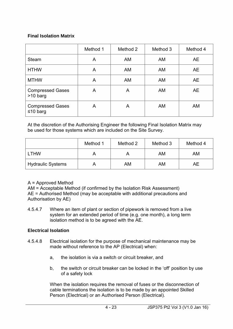
Method 1 Full System Depressurisation Method 2 Double Block and Bleed Method 3 Single Block, Bleed and Blank (or Spectacle Plate) Method 4 Single Block and Bleed

4 - 22 JSP375 Pt2 Vol 3 (V1.0 Jan 16)
4.5.4.5 Isolations in practice can involve 2 stages, for example, in implementing
Method 3 the initial isolation (Method 4) is an intermediate step, which may be of relatively short duration. This can be implemented without full system depressurisation provided that the time taken to implement the second stage of the isolation i.e. fitting the blank or spectacle plate is minimised and suitable precautions are taken. The initial stage does not require the issue of a Permit to Work and is to be controlled directly by the AP. Where this method is to be employed the Safety Programme and Statement of Isolation is to be countersigned by a second AP or the AE.
NOTE: Suitable precautions may include minimising personnel in the
area, ensuring all equipment is readily available before starting, allowing sufficient time for cooling or provision of, Personal Protective Equipment. Further guidance is available in ‘HSG 253 The Safe Isolation of Plant and Equipment’.
4.5.4.6 For short duration tasks, where the task would take less time to complete
than the installation and removal of the final stage of isolation, the use of a different method of isolation may be acceptable, this is to be considered carefully and be supported by the Isolation Risk Assessment. Further guidance is available in ‘HSG 253 The Safe Isolation of Plant and Equipment’. Alternative methods of final isolation not identified in the matrix below will require the written approval of the AE, e.g. freezing, or incorporating operation at reduced temperatures/pressures.
4 - 23 JSP375 Pt2 Vol 3 (V1.0 Jan 16)
Final Isolation Matrix
Method 1 Method 2 Method 3 Method 4
Steam A AM AM AE
HTHW A AM AM AE
MTHW A AM AM AE
Compressed Gases >10 barg
A A AM AE
Compressed Gases ≤10 barg
A A AM AM
At the discretion of the Authorising Engineer the following Final Isolation Matrix may be used for those systems which are included on the Site Survey.
Method 1 Method 2 Method 3 Method 4
LTHW A A AM AM
Hydraulic Systems A AM AM AE
A = Approved Method AM = Acceptable Method (if confirmed by the Isolation Risk Assessment) AE = Authorised Method (may be acceptable with additional precautions and Authorisation by AE) 4.5.4.7 Where an item of plant or section of pipework is removed from a live
system for an extended period of time (e.g. one month), a long term isolation method is to be agreed with the AE.
Electrical Isolation 4.5.4.8 Electrical isolation for the purpose of mechanical maintenance may be
made without reference to the AP (Electrical) when:
a, the isolation is via a switch or circuit breaker, and b, the switch or circuit breaker can be locked in the ‘off’ position by use
of a safety lock
When the isolation requires the removal of fuses or the disconnection of cable terminations the isolation is to be made by an appointed Skilled Person (Electrical) or an Authorised Person (Electrical).
4 - 24 JSP375 Pt2 Vol 3 (V1.0 Jan 16)
Fuel Oil Isolation 4.5.4.9 The AP may isolate and authorise maintenance on, a fuel oil supply to an
item of equipment provided that the fuel in question is Class III and that the work is within the confines of the boilerhouse or plantroom. Where fuel lines have to be disconnected or broken into to allow further work to proceed, the open end is to be capped or blanked off. Work on Fuel Oil installations outside the confines of the Boilerhouse, or work involving hot work or vessel entry is to be managed in accordance with JSP 375 Part 2 Volume 3 Chapter 5 – Petroleum.
Natural Gas/LPG 4.5.4.10 The disconnection of Natural Gas or LPG must be undertaken by a Corgi
registered (or other approving body) fitter and carried out in accordance with the current gas safety regulations.
4.5.4.11 Where any part of the system has been physically disconnected, a gas
soundness certificate must be issued prior to restarting the system. 4.5.4.12 The re-instatement of Natural Gas or LPG whether isolated or
disconnected must be undertaken by a Corgi registered (or other approving body) fitter and carried out in accordance with the current gas safety regulations.
4.5.4.13 For further information on Natural Gas and LPG see Appendix C. Safety Programme and Statement of Isolation 4.5.5.1 The Safety Programme and Statement of Isolation is to be signed by the
AP prior to implementation. 4.5.5.2 A Safety Programme and Statement of Isolation is to be implemented and
the Statement of Isolation Box on the front page signed by the AP before the issue of any permit.
4.5.5.3 Once the Safety Programme and Statement of Isolation is completed the
system or part of the system is deemed to be safe to work on. Multiple Permits can then be raised against this Safety Programme and Statement of Isolation.
4.5.5.4 Each Permit to Work against a Safety Programme and Statement of
Isolation must be reviewed by the AP to ensure that the isolation is suitable and sufficient for the proposed work under that Permit to Work.
4.5.5.5 Each Permit to Work raised against the Safety Programme and Statement
of Isolation must be recorded on the Safety Programme and Statement of Isolation.
4 - 25 JSP375 Pt2 Vol 3 (V1.0 Jan 16)
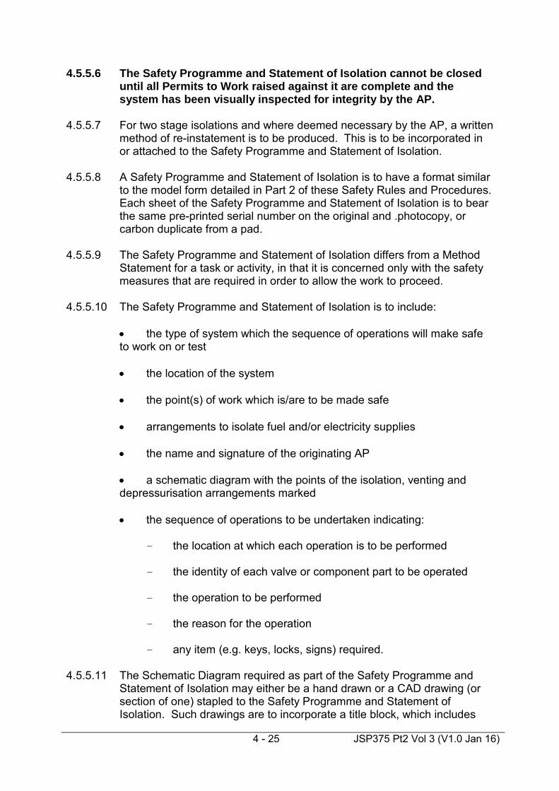
4.5.5.6 The Safety Programme and Statement of Isolation cannot be closed until all Permits to Work raised against it are complete and the system has been visually inspected for integrity by the AP.
4.5.5.7 For two stage isolations and where deemed necessary by the AP, a written
method of re-instatement is to be produced. This is to be incorporated in or attached to the Safety Programme and Statement of Isolation.
4.5.5.8 A Safety Programme and Statement of Isolation is to have a format similar
to the model form detailed in Part 2 of these Safety Rules and Procedures. Each sheet of the Safety Programme and Statement of Isolation is to bear the same pre-printed serial number on the original and .photocopy, or carbon duplicate from a pad.
4.5.5.9 The Safety Programme and Statement of Isolation differs from a Method
Statement for a task or activity, in that it is concerned only with the safety measures that are required in order to allow the work to proceed.
4.5.5.10 The Safety Programme and Statement of Isolation is to include:
• the type of system which the sequence of operations will make safe to work on or test • the location of the system • the point(s) of work which is/are to be made safe • arrangements to isolate fuel and/or electricity supplies • the name and signature of the originating AP • a schematic diagram with the points of the isolation, venting and depressurisation arrangements marked • the sequence of operations to be undertaken indicating:
- the location at which each operation is to be performed - the identity of each valve or component part to be operated - the operation to be performed - the reason for the operation - any item (e.g. keys, locks, signs) required.
4.5.5.11 The Schematic Diagram required as part of the Safety Programme and Statement of Isolation may either be a hand drawn or a CAD drawing (or section of one) stapled to the Safety Programme and Statement of Isolation. Such drawings are to incorporate a title block, which includes

4 - 26 JSP375 Pt2 Vol 3 (V1.0 Jan 16)
the Safety Programme and Statement of Isolation number, the name and signature of the AP and is to be dated upon issue of the Safety Programme and Statement of Isolation. Points of isolation, venting and depressurisation are to be clearly identified.
4.5.5.12 When the Safety Programme and Statement of Isolation has been
produced, including the sequence of operations, and is ready to be implemented, the AP is to secure the photocopy, or carbon duplicate from a pad in the Mechanical Systems Document Cabinet.
4.5.5.13 During implementation of the Safety Programme and Statement of
Isolation, the AP is to take the original to the Point of Work and annotate it with the time and date of each operation.
4.5.5.14 Where 2 Stage Isolation is being applied, a minimum of 2 people including
the AP must be present. This is to be detailed within the Isolation Risk Assessment and may include additional precautions in addition to the requirement for countersignature by a second AP or the AE.
4.5.5.15 Each isolation point is to be secured with a Safety Lock and a Safety Sign
fitted to the isolated item. 4.5.5.16 On completion of the sequence of operations, the AP is to sign the original
Safety Programme and Statement of Isolation box on the front of the Safety Programme and Statement of Isolation to confirm that the system has been isolated and place any Safety Keys used into a Safety Key Box.
4.5.5.17 The nature of the task/tasks to be implemented will determine if the keys
are to be locked in a standard Safety Key Box or a Safety Key Box which has the facility to fit a multi hasp. The AP is to retain and secure the AP Key from the Safety Key Box.
4.5.5.18 When a Safety Programme and Statement of Isolation has been
implemented, and the Statement of Isolation Box on the front page has been signed by the AP, the original Safety Programme and Statement of Isolation is to be posted in a prominent position in the APs’ Office.
4.5.5.19 Once isolations have been made or removed the actions are to be
recorded in the MSOR by reference to the Safety Programme and Statement of Isolation.
4.5.5.20 The AP is to ensure that the issue and cancellation of all associated
Permits to Work are recorded on the original Safety Programme and Statement of Isolation as well as documenting within the Mechanical Systems Operating Record.
4.5.5.21 If the completed original Safety Programme and Statement of Isolation is
lost the AP is to take a copy of the photocopy or carbon duplicate held in the Mechanical Systems Document cabinet, confirm that isolations and any significant departures, are in accordance with the Safety Programme

4 - 27 JSP375 Pt2 Vol 3 (V1.0 Jan 16)
and Statement of Isolation steps. A review of the Mechanical Systems Operating Record and Permit to Work file is to be undertaken in order to identify all related Permits to Work.
4.5.5.22 Isolation has been completed and all associated Permits to Work have
been cancelled, the AP is to cancel the original Safety Programme and Statement of Isolation prior to the implementation of the reinstatement. The original is then to be filed in the Mechanical Systems Document Register.
4.5.5.23 The closed out Safety Programme and Statement of Isolation is to be filed
in the Mechanical Systems Document Register for a period of not less than three years.
Permit to Work (Requirements) 4.5.6.1 A Permit to Work (PTW) is required where the integrity of a system is to be
breached (with the exception of the initial stage of a two stage isolation – see para 5.4.5), and when either:
• the system is classified as high risk or
• the system is classified as low risk and the Approved or Acceptable
Method of isolation is not achievable (see Final Isolation Matrix).
4.5.6.2 A Permit to Work is not required for routine operational tasks undertaken without the use of tools e.g. water treatment or draining receivers.
4.5.6.3 Work on Low Risk Systems where a PTW is not required is to be
controlled by the use of a Standing Instruction. 4.5.6.4 A PTW (Mechanical) is to have a format similar to the model form detailed
in Part 2 of these Safety Rules and Procedures. Each sheet of a permit is to be identified by the same pre-printed serial number on the original and photocopy, or carbon duplicate from a pad. Sets of consecutively numbered forms are to be used.
4.5.6.5 A PTW (MGPS) is to have a format similar to the model form detailed in
HTM 02 Part B Chapter 6, guidance on the use of Permit Books is in HTM 02 Part B Annex G.
4.5.6.6 A PTW (DAVS) is to have a format similar to the model form detailed in
Part 2 of these Safety Rules and Procedures, and comply with the requirements of NHS HTM 2022 Supplement No 1.
4.5.6.7 The AP is to issue the PTW immediately before work is to commence and
it is to remain in force until the work is completed.

4 - 28 JSP375 Pt2 Vol 3 (V1.0 Jan 16)
4.5.6.8 Whilst a PTW is in force a sign is to be displayed at the point of work clearly identifying that a Permit to Work is in force and giving contact details of the Duty Authorised Person.
4.5.6.9 A PTW is to be issued only to Skilled Persons or other APs (an AP cannot
issue a permit to himself). 4.5.6.10 A Permit to Work (Mechanical) is to state precisely and legibly:
• the system to be worked on
• the location of the system
• the proposed work
• the serial number of the Safety Programme and Statement of
Isolation
• where applicable, the serial number of any related PTW (e.g. Confined Spaces or Electrical).
Issue, Acceptance and Cancellation of Permits to Work 4.5.7.1 A Permit to Work is to be issued only at the point of work. The issue and
cancellation of every PTW is to be recorded in the Mechanical Systems Operating Record.
4.5.7.2 To comply with local or other MOD procedures the Duty AP is to ensure
that, where appropriate:
• the Maintenance Management Organisation (MMO) is informed of the proposed work and any loss of service
• permission is obtained from the client for the system to be taken out of service.
4.5.7.3 Before the issue of a PTW the Duty AP is to demonstrate to the Skilled
Person:
• the identity of the Mechanical System and the component parts to be worked on
• that the Mechanical System or component part has been isolated
• the safety arrangements at the place of work and at points of isolation
• any special instructions and/or safety measures

4 - 29 JSP375 Pt2 Vol 3 (V1.0 Jan 16)
• that the point(s) of work is/are de-pressurised, vented and drained, and that it is safe for the work to proceed.
4.5.7.4 Before the issue of a PTW the Duty AP is also to ensure that the Skilled Person is in possession of and understands the Task Risk Assessment and the Method Statement for the task. 4.5.7.5 Before accepting the PTW the Skilled Person is to:
• read the PTW and the Safety Programme and Statement of Isolation
• understand the extent of the work
• understand the safety precautions
• be prepared to undertake the work
• enter the PTW number on the Safety Programme and Statement of Isolation and sign it.
4.5.7.6 The Skilled Person is to sign the relevant Section of the PTW to accept the
responsibilities of the Person in Charge (PiC). On signing for acceptance of the PTW the Skilled Person authenticates the permit as valid and becomes the PiC of the permitted work.
4.5.7.7 The PiC is then to either take control of the PiC Key from the Safety Key
Box, or is to attach a unique padlock to the multi hasp on the Safety Key Box and take control of the key to that padlock.
4.5.7.8 The acceptance of a PTW identifies the PiC as personally responsible for
supervising or undertaking the defined work. The PIC retains the original Permit to Work until the task is completed or stopped.
4.5.7.9 While the work is in progress, the PiC is not permitted to leave the site or
to undertake any other work or tests. During any temporary absence of the PiC from the point of work, the work is to be halted. The PiC is to ensure that suitable safety precautions are taken and the AP informed, before leaving the point of work.
4.5.7.10 Where a change of PiC is required the PTW is to be closed and a new
PTW issued. The reason for closure of the PTW and status of the task is to be recorded on the original PTW and in the MSOR.
4.5.7.11 On completion of the work the PiC is to:
• withdraw all persons, equipment, tools and instruments from the point of work

4 - 30 JSP375 Pt2 Vol 3 (V1.0 Jan 16)
• advise all persons under his or her control that they are no longer permitted to work on the mechanical system
• complete and sign the relevant section of the original PTW
• complete and sign the entry on the Safety Programme and Statement of Isolation
• return the original PTW to the Duty AP
• return the PiC Key or remove the unique padlock from the multi hasp. 4.5.7.12 The Duty AP is to confirm that the work has been completed satisfactorily. 4.5.7.13 The Duty AP is to close the PTW by signing the original and filing it in the
MSOR. 4.5.7.14 If the Duty AP decides that it is necessary to stop the work, the PTW is to
be withdrawn and cancelled. The withdrawal is to be noted on the original PTW and the reasons for withdrawal and any actions taken are to be noted in the MSOR. A new PTW is required before re-starting work.
4.5.7.15 Where the work is stopped, the PTW is to be cancelled. The PiC is to:
• withdraw all persons and if appropriate all equipment, tools and instruments from the place of work • advise all persons under his or her control that they are no longer permitted to work on the system • amend the relevant Section of the original Permit to the effect that the work is incomplete and the point of work has been made safe • return the original PTW to the Duty AP • return the PiC Key or remove the unique padlock from the multi hasp.
4.5.7.16 Where the work is stopped and the PiC has returned the PTW, the Duty
AP is to annotate the Safety Programme and Statement of Isolation to highlight that work is not complete. This serves to prevent removal of the isolations until all associated work is complete and the integrity of the system has been restored.
4.5.7.17 If the PiC has lost the original PTW, the loss is to be recorded by the Duty
AP in the MSOR. The photocopy, or carbon duplicate from a pad of the PTW is then to be used in place of the original and cancelled in accordance with the above paragraphs. The PiC is to countersign the statements in the MSOR to confirm and acknowledge the loss of the PTW.

4 - 31 JSP375 Pt2 Vol 3 (V1.0 Jan 16)
4.5.7.18 Cancelled original Permits, together with their associated Risk Assessments and Safety Programme and Statement of Isolations are to be retained in an appropriate folder in the Mechanical Systems Document Cabinet for a minimum period of three years after the cancellation date.
Reinstatement on Completion of Work/Inspection 4.5.8.1 The isolation risk assessment is to identify the risks associated with the
reinstatement of the system on completion of work/inspection. Where the risk of reinstatement is identified as high, a documented reinstatement programme is to be produced and implemented under the supervision of the AP. The reinstatement programme is to be incorporated into the Safety Programme and Statement of Isolation or modelled on the “Sequence of Operations” section and attached to the “Safety Programme and Statement of Isolation”.
4.5.8.2 A reinstatement programme is required to be produced for all works
involving a two stage isolation in accordance with Section 4.5.4.5.

4 - 32 JSP375 Pt2 Vol 3 (V1.0 Jan 16)
Risk Assessment /Safety Programme / Permit to Work Process - Pt 1
Skilled Person (SP) / Person in Charge (PIC)Authorised Person (AP)Input Output
Task requiring isolation
Prepare isolation Risk assessment
(R.A.)Isolation R.A.
Raise Safety Programme & Statement of
Isolation (SP&SOI)
Place copy in Mechanical
Systems Document cabinet
Implement safety programme
annotating original with time & date of
operations
Has MMO been notified of
proposed work?
Is safety programme complete?
Notification to MMO/MO/DO
Sign Safety Programme
Yes
Yes
SP&SOI
No
Raise, or amend existing, Task Risk
Assessment(TRA)
Is TRA suitable & sufficient ?
Issue Permit to Work (PTW) & PIC key to SP.
Read, accept & sign PTW plus
enter PTW no. & sign SP&SOI .
SP becomes PIC
Signed PTW & SP&SOI
Task R.A.
Page 2Page 2
No
Yes
No

4 - 33 JSP375 Pt2 Vol 3 (V1.0 Jan 16)
Risk Assessment /Safety Programme / Permit to Work Process – Pt 2
OutputSkilled Person/Person in charge (PIC)APInput
Perform task
Is task complete?
1. Complete & sign PTW
2.Complete & sign entry on SP&SOI
3.Return original PTW to AP
1. Cancel PTW by signing original
2. Note cancellation in
MSOR
Have all PTWs on the SP&SOI been cancelled?
1. Cancel original SP&SOI.
2.File in MSD cabinet.
Yes
No
Cancelled original filed in Mechanical
Systems Document Cabinet
1. .Display original SP&SOI in AP
office.2. Entry to be
made in MSOR.
Page 1 Page 1
No
Yes
Updated MSOR

4 - 34 JSP375 Pt2 Vol 3 (V1.0 Jan 16)
Standing Instruction (Requirements) 4.5.9.1 Standing Instructions are issued by the Duty AP to Skilled Persons
(Mechanical) for both one-off and repetitive tasks on mechanical systems where a PTW is not appropriate.
4.5.9.2 A Standing Instruction is to contain the following information:
• location and type of system to which the instruction refers
• isolation procedure (if applicable)
• detail of tasks to be carried out
• special instructions or safety measures applicable
• name of Skilled Person
• employer
• validity period of Standing Instruction. 4.5.9.3 Standing Instructions must be specific and must contain sufficient detail
with respect to the procedure required to be undertaken by the Skilled Person to ensure that the system is safe before commencement of work. This may be in the form of an attached procedure detailing the method for isolation and de-pressurisation. There could be several such procedures supporting a Standing Instruction as it may cover more than one item or plant system.
4.5.9.4 Standing Instructions are to be supported by Risk Assessments that cover
both the isolation procedure and the task as per the requirements of Permits to Work and Safety Programmes & Statements of Isolation.
4.5.9.5 Standing Instructions (Electrical) issued by the Authorised Person
(Electrical) for electrical work such as fault finding in a boiler house control panel are outside the scope of these Safety Rules and Procedures.
4.5.9.6 A Standing Instruction is to have a format similar to the model form in Part
2 of these Safety Rules and Procedures. Each sheet of a Standing Instruction is to be identified by the same unique serial number on the original, the photocopy, or carbon duplicate from a pad.
Issue, Acceptance and Cancellation of Standing Instructions 4.5.10.1 Having understood the instruction(s) and being prepared to undertake the
task(s), the Skilled Person is to sign and accept the Standing Instruction. On signing for acceptance of the instruction a Skilled Person authenticates the instruction as valid and becomes the Person in Charge of the permitted task(s).

4 - 35 JSP375 Pt2 Vol 3 (V1.0 Jan 16)
4.5.10.2 In accordance with local or other MOD procedures the AP is to ensure
that, where appropriate:
• Persons in Charge inform the MMO of any task to be undertaken which may result in any loss of service
• Persons in Charge obtain permission from the MMO before taking mechanical systems out of service
• Skilled Persons are provided with a written instruction of the arrangements for informing the MMO of any loss of service.
4.5.10.3 The issue of a Standing Instruction is to be recorded in the MSOR. The
original copy of the Standing Instruction is to be issued to the Skilled Person. The duplicate copy is to be retained in the document register.
4.5.10.4 When an AP is appointed or returns to duty he is to review the MSOR to
check for any Standing Instructions in force. The AP is to familiarise himself with the contents of the extant Standing Instructions and annotate the MSOR to record this fact.
4.5.10.5 The Duty AP may cancel a Standing Instruction at any time. 4.5.10.6 On completion of the tasks outlined in the Standing Instruction or (for
repetitive tasks) on reaching the expiry date, the Person in Charge is to return the instruction to the Duty AP for cancellation. All Standing Instructions for repetitive tasks are to include an expiry date.
4.5.10.7 The Duty AP is to cancel the Standing Instruction by destroying the
duplicate copy and completing the cancellation section of the original document.
4.5.10.8 The cancellation of a Standing Instruction is to be noted in the MSOR. 4.5.10.9 Cancelled Standing Instructions together with their associated Risk
Assessments are to be placed in a folder marked “Standing Instructions - Cancelled Documents” and retained in the Mechanical Systems Document Cabinet for a minimum period of three years.
4.5.10.10 If the Person in Charge has lost the original Standing Instruction, the loss
is to be recorded by the Duty AP in the MSOR. The duplicate copy of the Standing Instruction is then to be used in place of the original and cancelled in accordance with the previous paragraphs. The Person in Charge is to countersign the statements in the MSOR to confirm and acknowledge the loss of the Standing Instruction.
4.5.10.11 A Standing Instruction is not to be transferred from one Skilled Person to
another.

4 - 36 JSP375 Pt2 Vol 3 (V1.0 Jan 16)
4.5.10.12 A Standing Instruction for repetitive tasks is to be valid for not more than three years but must be reviewed by an AP at intervals of not more than twelve months or following any change or modification to the system. Before issuing a new Standing Instruction the AP is to review the tasks on the expired instruction. This review is to be recorded in the MSOR.

4 - 37 JSP375 Pt2 Vol 3 (V1.0 Jan 16)
Standing Instruction Process
Authorised Person Skilled Person / Person in ChargeInput Output
Requirement for a one – off or
repetitive task on a mechanical
system.
1. Raise Standing Instruction & issue to Skilled Person
2. Retain duplicate in Document
Register
1. Read, understand & accept (sign)
Standing Instruction
2. Retain original
Completed S.I. signed by AP & Skilled Person /
Person in Charge
Inform & obtain permission from MMO for tasks which may / will result in loss of
service
Provide Skilled Person, in writing, arrangements for notifying loss of service to the
MMO
Notification / request to MMO
Record issue of S.I. in the MSOR
Updated MSOR
Perform task
Has S.I. reached its expiry date ?
1. Destroy duplicate copy2. Complete cancellation
section of original
Return S.I. to AP for cancellation
File in ‘S.I. – cancelled
documents’ folder in Mechanical
Systems Document Cabinet.
Cancelled Standing
Instructions to be retained for 3
years
Mechanical System Operating
Record ammended.
Yes
Review Standing Instruction
YesIs S.I. for a one-off
task?
Yes Retain S.I. for use on repeat tasks
No
No
Prepare isolation Risk Assessment (R.A.) if applicable
Isolation R.A,Raise (or amend
existing) Task R.A.
Is Task R.A acceptable?
Task R.A.No
Yes

4 - 38 JSP375 Pt2 Vol 3 (V1.0 Jan 16)
Training Introduction 4.6.1.1 The requirements for general training for APs and AEs are given
elsewhere in JSP 375 Part 2 Volume 3 and are not discussed further within this Section.
4.6.1.2 The requirement for training on Dental Air and Vacuum Systems (DAVS) is
deemed to be included in the approved training for Medical Gas Pipeline Systems (MGPS). Training on an approved DAVS-only course does not meet the requirements for AEs or APs with MGPS responsibilities.
Authorising Engineers (Mechanical) 4.6.2.1 AEs for the Mechanical discipline must achieve the same technical training
standards as given in Section 4.6.3, below, for an AP. 4.6.2.2 The AE for a site is to be involved in the selection and training
requirements of APs intended for duty on that site. Authorised Persons (Mechanical) 4.6.3.1 The AP is required to satisfactorily complete the necessary approved
training prior to his appointment to enable him to carry out the role. This training is made up of :
• initial training, which is common to all SRPs • the Mechanical Course • specialist technical training covering the systems for which the AP is
to be responsible. 4.6.3.2 The additional technical training may not necessarily refer to the Safety
Rules and Procedures (Mechanical). 4.6.3.3 An AP who is authorised by the AE to manage works on High Risk
Systems will have additional training in the particular fields required to enable him to manage those ‘High’ Risk Systems under his control. The AE must be in a position to demonstrate that such training has taken place.
4.6.3.4 The Mechanical Course is designed to teach APs how to implement the
Safety Rules and Procedures (Mechanical) and also provides a grounding in the management of risks.

4 - 39 JSP375 Pt2 Vol 3 (V1.0 Jan 16)
4.6.3.5 The course will cover:
• a review of system definitions and properties • an overview of associated Statutory Regulations • Pressure Systems Safety Regulations (PSSR) • an introduction to MOD Mechanical Safety Rules and Procedures • the scope of the Mechanical Safety Rules and Procedures • an overview of operational appointments • the specific roles and responsibilities of appointed personnel with respect to Mechanical Safety Rules and Procedures • Site Surveys, System Categorisation and Demarcation Agreements • Risk Assessment • Isolation Methodology and HSG 253 ‘Safe Isolation of Plant and Equipment’ • management, application and control of Mechanical Safety Rules and Procedures Documentation • Audit and Monitoring
Learning outcomes 4.6.3.6 On completion of the course, candidates will be able to:
• determine the differences between a High Risk and Low Risk System • understand the scope of ‘Mechanical Systems’ • demonstrate an understanding of the relevant legislation to work on
‘Mechanical Systems’ • demonstrate an understanding of Isolation Methodology and
Selection • describe the potential hazards and precautions to be taken to allow
safe work on Mechanical Systems • demonstrate familiarity with these Safety Rules & Procedures and
other relevant associated publications relating to Mechanical Systems

4 - 40 JSP375 Pt2 Vol 3 (V1.0 Jan 16)
• produce suitable and sufficient risk assessments for typical tasks on
Mechanical Systems • prepare Safety Programme and Statement of Isolations, Permits to
Work and Standing Instructions in accordance with these Safety Rules & Procedures
• describe the roles, duties and relationships between those parties
with operational appointments listed elsewhere in JSP 375 Part 2 Volume 3
• recognise the importance of familiarity with site installations and any
site specific procedures • describe what action to take when there are conflicting requirements
listed in Statutory Regulations, these Safety Rules & Procedures and any local rules
• understand the requirement for Demarcation Agreements
Assessment
4.6.3.7 On completion of the above training, candidates are to be assessed. The
assessment will include:
• an open book (clean SRP and supporting literature) examination, covering the topics identified above (one hour)
• a practical exercise involving the preparation of an Isolation Risk
Assessment, Safety Programme and Statement of Isolation, and PTW (up to issue stage) and the review of the prospective Person in Charge; all for a given scenario.
4.6.3.8 No specific time limit shall be given for the conduct of the practical
exercise. This is to be regarded as coursework to be completed before the end of the training course.
4.6.3.9 On completion of the Assessment, candidates will be graded as either,
“Satisfactory” or “Unsatisfactory” and a certificate issued to that effect. 4.6.3.10 Candidates who gain an unsatisfactory grading shall resubmit themselves
for re-assessment of the failed element(s), in order to have their grading reviewed. There is no requirement, to re-attend the entire course unless deemed necessary by the Training Provider in conjunction with the individual’s Authorising Engineer (or SAA in the case of an AE). The ‘re-assessment’ is to be undertaken within three months of initially attending the course.

4 - 41 JSP375 Pt2 Vol 3 (V1.0 Jan 16)
Skilled Persons (Mechanical) 4.6.4.1 To be eligible for appointment, prospective Skilled Persons (Mechanical)
are to meet the requirements of JSP 375 Part 2 Volume 3 Chapter 2 and are to have an appropriate qualification in a relevant discipline. Skilled Persons (Mechanical) are required to have successfully undertaken technical training as determined by the AP to meet the needs of his site and the task.
4.6.4.2 The suitability of a specific qualification will depend on:
• the work to be undertaken
• the type of mechanical system. Specific Requirements for Work on Natural Gas and LPG 4.6.5.1 Any individual working on Natural Gas and/or LPG must have successfully
undertaken technical and practical training and assessment to enable them to be a member of a class of persons approved by HSE, their registration must be applicable to the type of work and responsibilities found on the particular establishment(s).
4.6.5.2 They must hold a valid identity card as a member of a class of persons
approved by HSE (currently CORGI) with the relevant areas either endorsed on the rear of identity card or contained in a relevant certificate of competence from a Nationally Accredited Certification Body. See also Annex C.
Specific Requirements for Work on MGPS and DAVS 4.6.6.1 In addition to the general requirements for Skilled Persons, those working
on Medical Gas Pipeline Systems and Dental Gas Systems (where not directly employed by the MMO) must also be employed by a company registered to BS EN ISO 9000 with the scope of registration defined to include design, installation, commissioning and maintenance of MGPS as appropriate (DAVS is deemed to be included in the MGPS registration).
4.6.6.2 Organisations installing or maintaining DAVS must be able to verify
competence in appropriate techniques including supervision by qualified managers. Skilled Persons must be able to demonstrate that they are fully familiar with HTM 02 and with HTM 2022 Supplement 1. The Skilled Person must be qualified for the duties of the Competent Person as defined in HTM 02 Operational Management. The service provider must provide documentary evidence to this effect and evidence of the Skilled Person’s training and re-training.

4 - 42 JSP375 Pt2 Vol 3 (V1.0 Jan 16)
4.6.6.3 HTM 02 Part B Chapter 10 details procedures and rules for the competency of Skilled Persons. The Authorised Person has final authority in determining Skilled Person and contractor competency.
Specific Requirements for Work on Refrigeration 4.6.7.1 To be eligible for appointment for work undertaken in association with
Refrigeration Systems, prospective Skilled Persons are to meet the requirements given elsewhere in JSP 375 Part 2 Volume 3 and Annex E of this Chapter.
Acknowledgements These revised Safety Rules and Procedures have been produced by a joint Industry / Ministry of Defence working group comprising representation from the following contributing companies, organisations and individuals:
Atkins Defence Asset Management Aylan Associates Babcock Infrastructure Services Carillion Defence Estates Develop Training Interserve SERCO Turner Facilities Management

4A - 1 JSP375 Pt2 Vol 3 (V1.0 Jan 16)
Annex A
Boilers Introduction General Heating systems, hot water and steam boilers present hazards in terms of system operation, maintenance and repair. The principal hazards are the potential uncontrolled release of stored energy in the form of pressurised fluid and the potential of harm from contact with the heated fluid or heated surfaces. There are other secondary safety and environmental hazards. The pressure system isolation methods and proving techniques described elsewhere in these Safety Rules and Procedures (SRP Mechanical) are designed to be directly applicable to secure safety in heating systems, hot water and steam boilers. The isolation procedures are based on the HSE’s guidance document HSG 253 ‘Safe Isolation of Plant and Equipment’. In addition to the safe isolation and management procedures described elsewhere in these Safety Rules and Procedures, it is necessary to provide operating and maintenance instructions that provide a safe environment.
Model Instructions for Boiler Operators Introduction 4.A.1.1 With boiler installations there are many variations in items such as design
concept, layout, control logic, which make the start-up methods, operating procedures, emergency action and maintenance routines all by definition slightly different.
Operating Instructions and Records 4.A.2.1 It is a statutory requirement to provide instructions to individuals for the
purpose of ensuring safe operation of pressure systems. 4.A.2.2 Operating instructions are to include:
• start up and shut down procedures
• safety precautions
• the function and effect of all controls and safety devices.

4A - 2 JSP375 Pt2 Vol 3 (V1.0 Jan 16)
4.A.2.3 The following sub-sections list the main requirements. It is not intended to be used as a checklist.
Steam and Hot Water Pressure Systems 4.A.3.1 The Authorised Person is to draw up pre - firing, start up and operating
instructions for steam and hot water pressure systems, which are to include where appropriate:
• operation in accordance with manufacturers’ instructions
• methods of establishing the correct water level in a boiler
• blowdown procedures
• procedures for maintaining adequate water supplies to a boiler
• procedures for monitoring water quality
• water treatment regime
• procedures to avoid water hammer
• safe blowdown of a steam boiler or any part of the system requiring
treatment
• methods of carrying out any flue side gas purging
• methods of establishing correct firing conditions in order that pressure and temperature are raised carefully, preventing undue thermal shock
• precautions to be taken when emptying the boiler
• any other instructions affecting the safe operation of the pressure system.
4.A.3.2 Operating instructions are to be prominently displayed in boilerhouses and
plant rooms. Model Instructions for Steam Boiler Operators Pre-Lighting Up Checklist 4.A.4.1.1 Where appropriate, before lighting up a steam boiler ensure that:

4A - 3 JSP375 Pt2 Vol 3 (V1.0 Jan 16)
• boilerhouse ventilation inlet and outlet grilles are clean and free from obstruction
• boilerhouse ventilation fans are running
• the area adjacent to the boiler is clean and free of all combustible material
• forced draught fan inlet(s) is/are clean and free from obstruction
• hand operated flue dampers are OPEN
• smokebox and flue condensate drains are OPEN and clear of obstruction
• feed tank/hotwell water level is correct
• the feed water supply is available
• gauge glasses are clean and guards are in position
• gauges are indicating correctly
• all valves or cocks in the steam and water connections to the float chambers of water level controls are OPEN
• boiler pressure gauge valves or cocks are OPEN
• the pressure gauge indicates zero
• the boiler water level is correct
• the blow-down valve is CLOSED and not leaking
• boiler air-cocks are OPEN
• the steam range isolating valve (header valve) is CLOSED
• the drain valve on the pipe between the stop valve (crown valve) and the steam range isolating valve (header valve) is OPEN.
4.A.4.1.2 Where-starting a solid fuel fired boiler which has been 'banked', a fire door
is not to be opened until draught has been established for sufficient time to allow any accumulation of explosive gases in the combustion space and flues to be purged from the system.
4A - 4 JSP375 Pt2 Vol 3 (V1.0 Jan 16)
Procedure – Lighting Up and Warming Through 4.A.4.2.1 Where appropriate, carry out the following operations:
• check electrical power supply indicator light is on at the Burner/Stoker control panel
• switch firing equipment controls to 'MANUAL' setting
• initiate oil/gas burner light up sequence on 'Low-Flame' or ignite the solid fuel bed and initiate the operation of the mechanical stoker
• confirm that the automatic damper moves to the open position
• confirm that stable combustion conditions have been established
• control the warming through process by stopping and starting the burner or stoker in order to limit the temperature rise of the boiler water to the manufacturer's recommended rate
• purge air until a full flow of steam is evident and CLOSE air cocks
• as the boiler warms through check the tightness of manhole and handhole covers and their securing nuts
• when the boiler pressure begins to rise, control the rate of rise of pressure in accordance with the manufacturer's instructions
• continue to check the tightness of manhole and handhole covers and their securing nuts as the pressure rises
• carefully crack OPEN the stop valve (crown valve) to purge the line between the stop valve (crown valve) and the steam range isolating valve (header valve) of air and condensed water and allow the pipework to warm through
• when the line between the stop valve (crown valve) and the steam range isolating valve (header valve) is thoroughly warmed through CLOSE the line drains
• continue raising boiler pressure in accordance with the manufacturer's instructions until the system safe operating limit is reached
• at frequent intervals gradually open the line drains in the pipe between the stop valve (crown valve) and the steam range isolating valve (header valve) to ensure that the system remains clear of condensed water and to prevent the possibility of water hammer.

4A - 5 JSP375 Pt2 Vol 3 (V1.0 Jan 16)
4.A.4.2.2 Throughout the lighting up and warming through process the boilerhouse is to be regarded as fully operational. All necessary checks on the boiler and associated equipment are to be carried out. In particular regular checks are to be made on the boiler water level indicators and the operation of the boiler feed pump.
Procedure – Bringing a Boiler Onto Line 4.A.4.3.1 A boiler may be brought onto line either to pressurise a cold system or to
meet the demands of a system already under pressure. When the system is cold carry out the following operations:
• ensure the boiler pressure is raised to the safe operating limit by
following the procedure for lighting up and warming through
• check that system drain valves are OPEN
• check that system is adequately vented
• check that all system isolating valves, including those fitted to branch pipes, are CLOSED
• crack OPEN the steam range isolating valve (header valve)
• slowly warm through the header pipework and purge of air and condensate
• crack OPEN the system isolating valves at the header
• slowly warm through each section of pipework up to the next isolating valve and purge of air and condensate
• CLOSE the drain and vent points in that section of pipework, progressively continue the warming through process until each part of the system is at the required pressure and temperature
• slowly OPEN each isolating valve to its full extent
• slowly OPEN the steam range isolating valve (header valve) to its full extent
• slowly OPEN the stop valve (crown valve) to its full extent
• switch burner/stoker controls to 'AUTOMATIC'. 4.A.4.3.2 As the system is progressively brought onto line it may be necessary to
manually adjust boiler firing to meet the system demands.

4A - 6 JSP375 Pt2 Vol 3 (V1.0 Jan 16)
4.A.4.3.3 When the system is already under pressure carry out the following operations:
• ensure the boiler pressure is raised to the normal operating pressure
by following the procedure for lighting up and warming through
• crack OPEN the steam range isolating valve (header valve) until the system pressure is stabilised
• slowly OPEN the steam range isolating valve (header valve) to its full extent
• slowly OPEN the stop valve (crown valve) to its full extent
• switch burner/stoker controls to 'AUTOMATIC'.
Water Hammer 4.A.4.4.1 The admission of steam into a pipe in which there is an accumulation of
water may set the water into violent motion and generate a pressure wave. This is known as water hammer and is caused by either the sudden formation of a vacuum as steam in the system condenses rapidly or as condensate flow is suddenly restricted. The kinetic energy contained in water hammer may be sufficient to cause extensive damage or system failure.
4.A.4.4.2 Water hammer may be produced at any time by a slight variation in
conditions in steam pipes, particularly in parts of the system where condensate collects.
4.A.4.4.3 The sudden opening of drains is a frequent cause of water hammer. 4.A.4.4.4 To minimise the risk of water hammer in a system:
• OPEN Steam Valves very slowly
• should there be an indication of water hammer in the pipes, CLOSE the appropriate valve as soon as practical and ensure that the pipes are thoroughly drained before re-opening the valve
• install low capacity by-pass valves and use to purge condensate before opening main valves
• ensure the correct operation of steam traps in drain lines
• if necessary keep drains open sufficiently to prevent the accumulation of water

4A - 7 JSP375 Pt2 Vol 3 (V1.0 Jan 16)
• where it may be necessary to open drains on a pipe system suspected of containing water OPEN the drains gradually
• ensure that sufficient steam trap sets are installed in the system
• ensure that steam trap sets are correctly selected and maintained
• condensate drainage is to be sized to meet start-up demands
• improve quality of distributed steam
• ensure thermal insulation is installed and maintained
• maintain the pressure system in good condition. Hot Water Boilers Pre-Lighting Up Checklist 4.A.5.1.1 Where appropriate, before lighting up a hot water boiler ensure that:
• boilerhouse ventilation inlet and outlet grilles are clean and free from obstruction
• boilerhouse ventilation fans are running
• the area adjacent to the boiler is clean and free of all combustible material
• forced draught fan inlet(s) is/are clean and free from obstruction
• hand operated flue dampers are OPEN
• smokebox and flue condensate drains are OPEN and clear of obstruction
• the boiler is fully flooded
• the boiler main flow and return valves should be cracked OPEN
• the air vents should be OPENED and full flow of water proved
• the air vents should then be CLOSED
• the system pressure is being maintained at the correct level
• the feed water supply is available and at the correct pressure

4A - 8 JSP375 Pt2 Vol 3 (V1.0 Jan 16)
• boiler pressure gauge valves or cocks are OPEN
• pressure gauges are registering correct system pressures (marking should be on the gauge)
• system circulating pumps are running
• burner fuel connections are free of leaks
• air damper linkages and actuators are operational
• the combustion chamber is free from any accumulation of oil
• swing-open burners are in the closed position for firing
• the locking devices are secure
• the burner fuel supply and return valves are OPEN. 4.A.5.1.2 When re-starting a boiler that has been 'banked', a fire door is not to be
opened until draught has been established for sufficient time to allow any accumulation of explosive gases in the combustion space and flues to be purged from the system.
Procedure – Lighting Up and Warming Through a Boiler Rated Up To 3 MW(TH) 4.A.5.2.1 Where appropriate, carry out the following operations:
• check electrical power supply indicator light is on at the Burner/Stoker control panel
• fully OPEN boiler flow and return valves
• start recirculating pumps and circulate system water through the boiler prior to commencing firing
• if heat is available in the water returning to the boiler, delay firing until the flow temperature of the boiler is approximately the same as the return temperature
• initiate the firing control of the burner or ignite the fuel bed and initiate the operation of the mechanical stoker
• check that the automatic damper moves to a safe open position
• confirm that stable combustion conditions have been established.

4A - 9 JSP375 Pt2 Vol 3 (V1.0 Jan 16)
4.A.5.2.2 Throughout the lighting up and warming through process the boilerhouse is to be regarded as fully operational. All necessary checks on the boiler and associated equipment are to be carried out.
Procedure – Lighting Up and Warming Through a Boiler Rated Above 3 MW(TH) 4.A.5.3.1 Where appropriate, carry out the following operations:
• check electrical power supply indicator light is on at the Burner/Stoker control panel
• fully OPEN boiler flow and return valves
• start recirculating pumps and circulate system water through the boiler prior to commencing firing
• if heat is available in the water returning to the boiler, delay firing until the flow temperature of the boiler is approximately the same as the return temperature
• switch firing equipment controls to 'MANUAL' setting
• initiate oil/gas burner light up sequence on 'Low-Flame' or ignite the solid fuel bed and initiate the operation of the mechanical stoker
• confirm that the automatic damper moves to the open position
• confirm that stable combustion conditions has been established
• control the warming through process by stopping and starting the burner or stoker in order to limit the temperature rise of the boiler water to the manufacturer's recommended rate
• as the boiler warms through, check the tightness of manhole and handhole covers and their securing nuts
• continue raising boiler temperature in accordance with the manufacturer's instructions until the system safe operating limit is reached
• when the safe operating limit is reached switch the burner/stoker controls to 'AUTOMATIC' setting.
4.A.5.3.2 Throughout the lighting up and warming through process the boilerhouse
is to be regarded as fully operational. All necessary checks on the boiler and associated equipment are to be carried out.

4A - 10 JSP375 Pt2 Vol 3 (V1.0 Jan 16)
Emergency Procedures General 4.A.6.1.1 Report immediately, any accident or mishap involving fireside explosion,
loss of water or water hammer. 4.A.6.1.2 Notices are to be fixed in Boilerhouses requiring persons to report defects
to the Authorised Person via a continually manned telephone number. In Case of Fire 4.A.6.2.1 Raise the alarm in accordance with local arrangements for the building or
site and then take action as follows, if safe to do so:
• isolate electricity supply
• operate the emergency shut-off to the main fuel system fire valve where fitted
4.A.6.2.2 Fire action notices complying with current regulations are to be fixed in
boilerhouses requiring persons to report fire to the appropriate authority. Failure of Electricity Supply 4.A.6.3.1 Where boilerhouses have a second source of electricity, the following
actions should be taken where applicable:
• initiate changeover sequence if manually operated
• reset and start water circulating pumps
• reset burner/stoker and fire boiler. 4.A.6.3.2 Where applicable:
• illuminate water gauge glasses, temperature, pressure gauges and other relevant controls with battery-operated lamps or torches
• if necessary to avoid boiler water loss to the steam distribution system CLOSE the most convenient isolating valves and dampen down or withdraw fires
• aid water circulation by opening all standby circulating pump valves
• observe the water level in the pressurisation unit and adjust the nitrogen pressure as a precaution against drawing nitrogen into the system and to avoid the generation of flash steam.

4A - 11 JSP375 Pt2 Vol 3 (V1.0 Jan 16)
Restoration of Electricity Supply 4.A.6.4.1 Restore the system to normal conditions and re-start boilers and
associated equipment. Loss of Boiler Water Level (Steam Boilers) 4.A.6.5.1 If the water level is not indicated in the gauge glass when the boiler is
steaming, immediate action is to be taken. Boiler Operators are to act according to their best judgement and knowledge of events prior to the occurrence. The following actions are to be considered:
• all persons are to withdraw from the vicinity of the boiler at once
• operate the emergency shut-off to the main fuel system fire valve
where fitted
• operate any other emergency or shut off devices
• vacate the boilerhouse
• warn anyone in the immediate neighbourhood that it is likely that an explosion or serious accident may be about to occur and take actions to prevent any person approaching or entering the boilerhouse
• inform the emergency services in accordance with local procedures.


4B - 1 JSP375 Pt2 Vol 3 (V1.0 Jan 16)
Annex B Compressed Air General 4.B.1.1 Compressed air is a relevant fluid as defined by the Pressure System
Safety Regulations. As air is compressible, it can contain a large amount of stored energy for a given volume and this characteristic can present a danger to those who operate and maintain compressed air systems. The Health and Safety Executive produce a guidance booklet (HSG 39 Compressed Air Safety) which is essential reading for those involved with designing, manufacturing, installing, operating or otherwise involved with compressed air systems and plant. BS 6244 (Code of Practice for Stationary Air Compressors) provides further guidance on compressed air safety.
Demarcation of Authorised Persons (Mechanical) Roles and Responsibilities and those who operate compressed air plant 4.B.2.1 The AP (Mechanical) has a responsibility to ensure that:
• compressed air plant is safe to operate and maintain
• those maintaining the compressed air system have appropriate competencies for the tasks they are required to carry out
• installation and plant deficiencies have been recorded and brought to the attention of the Maintenance Management Organisation
• appropriate warning notices and safety posters are displayed in the plant room.
4.B.2.2 APs may have no direct responsibility for the actions of those operating
such plant in the course of day to day activities. They do however have a duty (under the Health and Safety at Work Act) to bring to the attention of the operators’ line management any unsafe working practices or equipment deficiencies that those operating the plant may be using.
Control of Works 4.B.3.1 Where there are small single compressor/receiver units, as per HSG 39,
supplying one or two outlets only (typical of installations found in motor transport facilities) it is acceptable for an appropriately experienced and qualified Skilled Person to carry out maintenance tasks (including those that breach the integrity of the system itself) without the intervention of an AP. Such maintenance tasks need to be detailed on a Standing Instruction.
4B - 2 JSP375 Pt2 Vol 3 (V1.0 Jan 16)
4.B.3.2 Compressed air systems which have a more complex distribution system
or include more than one air receiver or by virtue of risk assessment constitute a risk which requires further controls, must be subject to the Permit to Work procedures described in these Safety Rules and Procedures.
Plant and Equipment Safety Identification 4.B.4.1.1 For safety reasons compressed air pipelines must be identified by a colour
code in accordance with BS1710. Automatically controlled plant must have signs warning that the plant may start automatically the design of which must comply with the Safety Signs and Signal Regulations.
Air Intake and Plant Room Ventilation 4.B.4.2.1 Inlet air to compressors should be drawn from an area, which is free from
potentially flammable or corrosive concentrations of fumes or vapours, or from moisture-laden air. Adequate ventilation of the plant room in which the air compressor plant is sited must be provided and take into account the heat generated from the compression process as well as the risk to the system from low ambient temperatures. Appropriate signage (both internal and external) must be affixed adjacent to these air intakes. Ideally compressors should not be sited in boiler houses. Where this is the case, the air inlet to the air compressor should ideally be ducted from an external source.
Operating Instructions 4.B.4.3.1 All compressed air systems, plants and accessories shall have proper and
comprehensive operating instructions, a copy of which should be readily available to staff responsible for operation.
4.B.4.3.2 The AP is responsible for ensuring that emergency procedures are in place
which cover:
• any failure that results in the uncontrolled release of compressed air
• over pressurisation
• any other occurrence likely to cause danger. Maintenance Tasks 4.B.4.4.1 Maintenance is to be carried out in accordance with manufacturer’s
instructions and MOD guidelines. There are also general requirements (for maintenance) set out in the Health and Safety at Work Act (Section 2(2)(a))

4B - 3 JSP375 Pt2 Vol 3 (V1.0 Jan 16)
and the Provision and Use of Work Equipment Regulations. HSG 39 also provides some guidance on maintaining compressed air systems including the requirement for designers, manufacturers and installers to provide guidance on maintenance of compressed air plant and systems.
4.B.4.4.2 The discharge from a compressor may deposit oil residues on the exhaust
chamber, the discharge pipe and in the receiver. The oil residues can build up and if exposed to high temperatures may ignite. This can, and has resulted in fire in the compressed air pipework. Subject to a risk assessment it may be necessary for the compressor head and discharge pipes to be removed and cleaned internally at least once per year. Over temperature devices must be installed in the compressor discharge to switch off the plant in the event of high temperatures occurring if a risk assessment identifies this as a control measure.
Training 4.B.4.5.1 All Skilled Persons are to have received suitable and sufficient training to
ensure and demonstrate their competence for the installed systems to the satisfaction of the AP.
Useful References 4.B.5.1 Further information is detailed in HSG 39


4C - 1 JSP375 Pt2 Vol 3 (V1.0 Jan 16)
Annex C Natural Gas and LPG Introduction and Scope 4.C.1.1 The Gas Safety (Installation and Use) Regulations place responsibilities on
a wide range of people, including those installing, servicing, maintaining or repairing gas appliances and other gas fittings; as well as suppliers and users of gas. The Regulations deal with the safe installation, maintenance and use of gas fittings, appliances and flues and generally apply to any gas as defined in the Gas Act and Gas Safety (Management) Regulations.
4.C.1.2 These Safety Rules & Procedures set out the requirements for the
management and control of work on gas systems, appliances and ancillary equipment that fall within the scope of the Regulations. These procedures cover gas systems internal to a building; all external distribution pipe work and storage vessels are subject to JSP 375 Part 2 Volume 3 Ch. 5 – Petroleum.
4.C.1.3 For non-UK establishments, the MMO is to agree with the SAA a regime
equal or equivalent to that operated and managed by the UK Registration Body identified in 4.C2.2.2.
Management of Work on Gas Fittings 4.C.2.1 The principal requirement of this procedure is to ensure that any work on
Natural Gas and LPG Systems and associated appliances in any workplace, site or premises, is carried out by a ‘competent person’.
Roles and Responsibilities 4.C.2.2.1 This encompasses all those who are involved in the execution,
supervision, management and monitoring of work on Gas Systems. 4.C.2.2.2 The Registration Body (currently Gas Safe Register) is appointed by the
Health & Safety Executive to operate a mandatory registration scheme for competent businesses which carry out gas work.
4.C.2.2.3 Specifically, the Registration Body will:
• carry out an initial review, and where appropriate, register businesses as competent to carry out work on Gas Systems
• carry out routine audits and assessments of the management arrangements of businesses registered for work on Gas Systems

4C - 2 JSP375 Pt2 Vol 3 (V1.0 Jan 16)
• carry out an initial review, and where appropriate, register individuals who are assessed as competent to work on Gas Systems
• carry out routine continuous assessments of individuals who are assessed as competent to work on Gas Systems.
4.C.2.2.4 With regard to the management of work on gas systems, the AE will:
• Confirm that a sufficient number of Responsible Persons (Gas) are appointed with specific responsibility for the management of work on Gas Systems
• ensure that a demarcation agreement is drawn up and agreed with the AE Petroleum. This is to be in the form of a schematic drawing for each gas distribution system, and is to be displayed in the AP Office and available to all interested parties
• confirm in writing for each site or geographical area the custodian of the Schematic Drawings & Register of Gas Appliances.
4.C.2.2.5 The Responsible Person (Gas) will:
• ensure that, where a company is employed to work on Gas Systems, the individuals concerned are registered with the Registration Body and have a certificate of competence appropriate to the type of work and system to be worked upon
• maintain, for each geographical area, a database of sites on which Gas Systems are maintained or operated
• ensure that, for each geographical area, a database of competent staff (Approved Gas Fitters) is maintained
• ensure that a schematic drawing detailing the pipe work installation in each building is maintained and available to all Approved Gas Fitters
• ensure that a register of every gas appliance and flue is maintained and available to all Approved Gas Fitters
• undertake six monthly checks of the system documents & records. 4.C.2.2.6 Every company employed to carry out work on gas systems, appliances or
ancillary equipment on the MOD Estate is to have suitable and sufficient management and procedures in place to discharge the duty of the Employer under the regulations.

4C - 3 JSP375 Pt2 Vol 3 (V1.0 Jan 16)
4.C.2.2.7 The Employer of an Approved Gas Fitter will:
• obtain and maintain Corporate Registration from the Registration Body
• ensure that, where directly employed staff are engaged on work on Gas Systems, the individuals are trained to the appropriate standards and registered with the Registration Body and have a certificate of competence appropriate to the type of work and system to be worked upon
• ensure that, where a sub-contractor is employed to work on Gas Systems, the individuals concerned are registered with the Registration Body and have a certificate of competence appropriate to the type of work and system to be worked upon
• maintain records of training of individuals assessed as competent and any assessments carried out by the Registration Body
• ensure that records of employment, training and assessment of ‘competent persons’ are available to the Authorising Engineer and Responsible Person (Gas) for audit purposes
• ensure that any modifications to installed pipe work are communicated to the Responsible Person (Gas) including the provision of an updated schematic drawing for the installation
• ensure that the Responsible Person (Gas) is informed of the installation or removal from a site of any gas appliance and/or flue
• undertake routine checks of all employees and sub-contractors employed on gas works.
4.C.2.2.8 Approved Gas Fitters will:
• carry out work in a competent manner in accordance with industry best practice
• co-operate with management in the adoption of safe systems of work as dictated by both this and other MOD Safety Rules & Procedures
• advise management of any work situation which could result in either serious or immediate danger to health and safety.

4C - 4 JSP375 Pt2 Vol 3 (V1.0 Jan 16)
Assessment of Risk 4.C.3.1 In terms of gas equipment, all risks to health and safety are to be
assessed taking into account all relevant factors. Specific emphasis is to be placed on effective measures to prevent access to any dangerous parts of equipment.
Competence 4.C.4.1 Approved Gas Fitters: The Approved Gas Fitter, must have current
registration with the Registration Body (Gas Safe Register) appropriate to the Gas System on which they are to work.
4.C.4.2 The Responsible Person (Gas) will, in order to be assessed and appointed
for responsibilities with respect to gas systems:
• have a sound understanding of the Gas Safety (Installation & Use Regulations)
• have a basic knowledge of other Health & Safety related legislation
• understand the competency requirements for Approved Gas Fitters
• have a technical appreciation of Gas Systems including the difference between various systems, the combustion process, the mechanics of gas safety control gear, ventilation requirements and gas pipe work
• have a sound understanding of the Registration Body’s quality management systems as applied to work on Gas Systems.
Employer’s Duty 4.C.5.1 It is the duty of the Maintenance Management Organisation (MMO) to
ensure that any gas appliance, installation pipe work or flue installed at any place of work under the MMO’s control is maintained in a safe condition.
4.C.5.2 For specific requirements, reference is to be made as appropriate to the
Regulations, standards and manufacturer’s instructions. An inspection of the physical condition of equipment for deterioration, performance tests and cleaning are to be addressed.
Safety Precautions 4.C.6.1 Any gas appliance, installation pipe work, flue or fitting installed at any
place of work is to be maintained in a safe condition so as to prevent risk of injury.

4C - 5 JSP375 Pt2 Vol 3 (V1.0 Jan 16)
4.C.6.2 No person shall carry out any work in relation to gas in such a manner that gas could be released, unless steps are taken to prevent the gas so released constituting a danger.
4.C.6.3 No person carrying out work in relation to gas equipment shall leave the
undertaking unattended unless every incomplete gas-way has been sealed with the appropriate fitting or the gas equipment is otherwise safe.
4.C.6.4 When carrying out work in relation to gas equipment which involves
exposing gas ways which contain or have contained flammable gas the Approved Gas Fitter shall not smoke or use any source of ignition in such a manner as may lead to the risk of fire or explosion.
4.C.6.5 No person searching for an escape of gas shall use any source of ignition. 4.C.6.6 Where a person carries out any work in relation to gas equipment which
might affect the gas tightness of the installation they shall immediately thereafter test the installation for tightness at least as far as the nearest valves upstream and downstream of the works.
4.C.6.7 No person shall install a gas storage vessel unless the site where it is to
be installed is such as to ensure that it can be used, filled or refilled without causing danger.
Protection against Damage 4.C.7.1 Gas equipment is to be installed or replaced in accordance with
appropriate standards and the manufacturer’s instructions. The Gas Appliances (Safety) Regulations require such instructions to accompany appliances. Where the appliance is installed in domestic premises, these instructions are to be held at the premises and a copy held by the Responsible Person (Gas). Where the appliance is installed in a non-domestic premise, these instructions are to be held by the Responsible Person (Gas).
4.C.7.2 Gas equipment is not to be installed or replaced if there is reason to
suspect that foreign matter may block or otherwise interfere with the safe operation of the fitting unless a suitable filter or other protective device is fitted.
4.C.7.3 Gas equipment is not to be installed or be replaced in a position where it is
likely to be exposed to any substance which may corrode the equipment, unless it is constructed of materials which are inherently resistant to corrosion, or it is suitably protected against such corrosion.
Existing Gas Equipment 4.C.8.1 No person shall make any alteration to any premises or site in which a gas
storage vessel is fitted if that alteration would adversely affect the safety of the fitting or vessel such that, if the fitting or the vessel had been installed

4C - 6 JSP375 Pt2 Vol 3 (V1.0 Jan 16)
after the alteration, there would have been a contravention of or failure to comply with the Regulations
4.C.8.2 No person shall do anything which would affect a gas fitting or any flue or
means of ventilation used in connection with the fitting in such a manner that the subsequent use of the fitting might constitute a danger to any person
Installation of Gas Appliances 4.C.9.1 No person shall install a gas appliance unless:
• the appliance and the gas fittings and other works for the supply of gas to be used in connection with the appliance are safe
• there is a means of removal of the products of combustion from the appliance
• there is a sufficient permanent supply of air for the appliance for proper combustion
• there is a means of ventilation to the room or internal space in which the appliance is to be used, and
• the general conditions of installation including the stability of the appliance and its connection to any other gas fitting are correct.
Servicing Gas Appliances 4.C.10.1 Where an Approved Gas Fitter services a gas appliance, his/her Employer
is to ensure that the Approved Gas Fitter shall immediately thereafter examine:
• the effectiveness of any flue
• the supply of combustion air
• its heat input and operating pressure
• its safe functioning.
4.C.10.2 Where a defect is found during the course of the activity the Approved Gas
Fitter is to immediately notify the responsible person for the premises where the appliance is situated and in turn his/her Employer and the Responsible Person (Gas).

4C - 7 JSP375 Pt2 Vol 3 (V1.0 Jan 16)
Flues 4.C.11.1 No person shall install a gas appliance to any flue unless the flue is
suitably constructed and in a proper condition for the safe operation of the appliance, also no person shall:
• install a flue pipe so that it enters a brick or masonry chimney in such
a way that the seal between the flue pipe and the chimney cannot be inspected
• connect a gas appliance to a flue which is surrounded by an enclosure unless that enclosure is so sealed that any spillage or products of combustion cannot pass from the enclosure into any room or internal space in which the appliance is installed
• install a power operated flue system for gas appliance unless it safely prevents the operation of the appliance if the draught fails.
Flue Dampers 4.C.12.1 Any person who installs an automatic damper to serve a gas appliance
shall:
• ensure that the damper is so interlocked with the gas supply to the burner, that burner operation is prevented in the event of failure of the damper when not in the open position
• immediately after installation examine the appliance and the damper to verify that they can be used together safely without constituting a danger to any person or property.
4.C.12.2 Manually operated dampers to flues are not to be installed to serve any
gas appliance unless the damper is permanently fixed in the open position. Suspended Appliances 4.C.13.1 A suspended gas appliance is not to be installed unless adequately
supported in accordance with the appliance manufacturer’s installation instructions.
Escape of Gas 4.C.14.1 Gas escapes are to be dealt with immediately they are identified and are to
take priority over all other work. The Approved Gas Fitter should be capable of taking charge of the situation to ensure that the correct procedure for dealing with a gas escape is strictly observed. In the absence of an Approved Gas Fitter, the method of isolation of the gas supply is to be readily identifiable and be suitable to make safe immediately.

4C - 8 JSP375 Pt2 Vol 3 (V1.0 Jan 16)
4.C.14.2 Isolation valves, emergency shut off valves, and isolation devices are to be easily identified by being labelled, colour coded and signed where appropriate. Plant rooms and mains inlet points are to be supported by valve charts and diagrams showing the routes of gas pipe work, isolation points, and other safety features.
Unsafe Situations 4.C.15.1 Unsafe situations are to be dealt with in accordance with the relevant
Publication summarised below.
Dealing with Unsafe Situations
Is the appliance / installation existing?
Is the appliance / installation Immediately
Dangerous (ID)? (1)
Has permission been granted to disconnect
and cap off?
Inform Transco Gas Emergency Service call
centre. Record details and time of day
Attach warning label (4), Complete Warning /Advice Notice (5). Ask responsible person to sign document &
issue copy.
The Gas Emergency Service Provider will disconnect and
cap off the appliance / installation.
Complete RIDDOR form F2508G2 (where
appropriate) and send to HSE within 14 days (6).
Is the installation or appliance At Risk
(AR)? (2)
Is the installation or appliance Not to
Current Standards (NCS)? (3)
Turn off the Appliance
Attach warning label (4). Complete Warning /
Advice Notice(5).Responsible person to sign document & issue
copy.
Verbally inform the responsible
person. Record details on
Warning / Advice notice (5) or job
record.
Disconnect and cap off appliance /
installation.
Attach Warning Label (4). Complete
Warning / Advice Notice (5).
Responsible person to sign document and
issue copy.
Can the appliance be commissioned in
accordance with the Gas Safety (Installation & Use)
Regulations?
Commission the appliance & put
into use.
Disconnect, cap off & label the
appliance. inform the responsible
person.
Start
NO
YES
YES
YES
NO
YES YES
NO
YES
NO
(1) One which if operated or left connected to a gas supply will be an IMMEDIATE danger to life or property.
(2) One which if operated may lead to a situation which COULD create risk to life or property.
(3) One which is not in accordance with current Regulations, Codes of Practice or Standards and Specifications, but does NOT constitute either an Immediately Dangerous or At Risk situation.
(4) The CORGI WL1 or TG3 Warning Label.
(5) The CORGI CP14 Warning / Advice Notice reporting form.
(6) The F2508G2 forms are available from CORGI or the HSE.

4C - 9 JSP375 Pt2 Vol 3 (V1.0 Jan 16)
Test and Inspection 4.C.16.1 Regular inspection of equipment is an essential part of any preventive
maintenance programme. Records of maintenance, including inspection and test results are to be maintained preferably throughout the life of equipment. Completion and/or test certificates are mandatory. The documents are obtainable through Gas Safe Register or where appropriate produced under local arrangements, but to the same level of detail.
4.C.16.2 The following lists the documents most common to the MMO’s activities
and are to be processed when applicable, copies of which are to be issued to and held by the Responsible Person (Gas):
• Gas Safety Inspection
• Landlord’s Gas Safety Record
• Electrical Cross Bonding
• Combustion Report Form
• Warning/Advice Notice.
Dangerous Occurrence 4.C.17.1 The Responsible Person (Gas) is to ensure that any dangerous
occurrence is reported in accordance with the Reporting of Injuries, Diseases, and Dangerous Occurrences Regulations. Near misses are to be reported to the SAA (Mechanical), via the AE.
Audit and Monitoring 4.C.18.1 System audits will be conducted by the Authorising Engineer. 4.C.18.2 System audits will review, as a minimum the existence and continued
competence of the Appointments mandated by this procedure and the existence and completeness of the documents referred to in this procedure.
4.C.18.3 Monitoring of work on Gas Systems will be undertaken as required, by the
Employer. This will include checks on the current Registration of the Approved Gas Fitters; the adherence to safe work instructions and Quality Assurance procedures; witnessing the results of tests and the checking of any completed records.
4.C.18.4 Audits and monitoring by the Employer of an Approved Gas Fitter are to be
carried out as required to satisfy the requirements and maintain registration with the Registration Body.
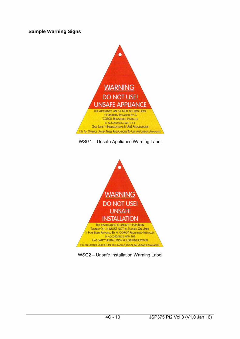
4C - 10 JSP375 Pt2 Vol 3 (V1.0 Jan 16)
Sample Warning Signs
WSG1 – Unsafe Appliance Warning Label
WSG2 – Unsafe Installation Warning Label

4C - 11 JSP375 Pt2 Vol 3 (V1.0 Jan 16)
Sample Warning/Advice Notice


4D - 1 JSP375 Pt2 Vol 3 (V1.0 Jan 16)
Annex D Industrial Gases Introduction 4.D.1.1 The Scope of Industrial Gases found across the Defence Estate varies
widely. Guidance on the Management of Industrial Gases can be found in JSP 319.
4.D.1.2 Any Industrial Gas Systems in a particular location should be inspected by
the Authorising Engineer (Mechanical) during the site survey and an assessment carried out based on system risk as to whether any special precautions or arrangements are to be implemented on that system.
4.D.1.3 These systems may need individual guidance notes to be produced by the
Authorising Engineer for that particular system and location.


4E - 1 JSP375 Pt2 Vol 3 (V1.0 Jan 16)
Annex E Refrigeration Plant General 4.E.1.1 Refrigeration systems present both safety and environmental hazards in
terms of system operation, maintenance and repair as well as with regards to refrigerant handling.
4.E.1.2 The standard pressure system isolation methods and proving techniques
advocated elsewhere in these Safety Rules and Procedures may not be appropriate for refrigeration. Decanting refrigeration medium for example will require access to the pressurised elements of the equipment.
4.E.1.3 BS EN 378:2000 (Refrigeration systems and heat pumps – Safety and
environmental requirements) provides further guidance on refrigeration safety. Only those Authorised Persons (Mechanical) who have an appropriate refrigeration endorsement on their Certificate of Appointment will be authorised to control access to refrigeration plant and systems for maintenance purposes.
AP Mechanical Roles and Responsibilities applied to Refrigeration Systems 4.E.2.1 The Authorised Person has responsibility to ensure that:
• refrigeration plant is safe to maintain
• those maintaining the refrigeration systems are competent for the tasks they are required to carry out
• installation and plant deficiencies have been recorded and brought to the attention of the management of the Maintenance Management Organisation
• appropriate warning notices and safety posters are displayed in refrigeration system plant rooms including COSHH data sheets where appropriate
• workplace risk assessments have been carried out and that suitable control measures are in place
• co-ordination between those carrying out refrigeration maintenance tasks, the Maintenance Management Organisation and those responsible for enforcing other MOD Safety Rules and Procedures (such as Confined Spaces and Electrical, as well as any local safety procedures such as those relating to hot work permits)

4E - 2 JSP375 Pt2 Vol 3 (V1.0 Jan 16)
• those tasked with maintaining refrigeration systems have access to workplace based risk assessments prior to any specific maintenance task being carried out.
Control of Refrigeration Plant Maintenance 4.E.3.1 The Authorised Person controls access to refrigeration plant for
maintenance purposes. 4.E.3.2 Prior to any specific maintenance tasks being carried out, the Authorised
Person will verify the competencies of those operatives who have been allocated the particular maintenance task on specific refrigeration plant or equipment, with a view to applying the formal Skilled Person appointment procedures (described elsewhere in these Safety Rules and Procedures).
4.E.3.3 Those tasked with carrying out the refrigeration maintenance task are
required to provide a risk assessment and method statement to cover the specific maintenance tasks (i.e. a Task Risk Assessment) which takes into account the risks and associated control measures in the workplace based risk assessment, these must be in accordance with EC Regulation 842/2006. The Authorised Person reviews the method statement and risk assessment jointly with those responsible for the maintenance tasks to ensure the risks are suitably controlled and the method statement accords with any operational imperatives.
4.E.3.4 The Authorised Person can then control the tasks needed to be carried out
on the refrigeration plant by:
• Standing Instruction
• Safety Programme and Statement of Isolation
• Permit to Work
depending on the risks involved and based on the refrigeration company’s Task Risk Assessments and Method Statements.
4.E.3.5 Isolation methods and controls will be jointly agreed and will reflect
refrigeration engineering requirements and best practice. 4.E.3.6 It is therefore acceptable (providing the risks are controlled) for an
appropriately experienced and qualified refrigeration Skilled Person to carry out maintenance tasks (including those that breach the integrity of the system itself) without invoking a Permit to Work procedure. Such maintenance tasks need to be detailed on a Standing Instruction.
4.E.3.7 The Skilled Person must isolate and depressurise the system as well as
apply his own safety locks in accordance with the Safety Programme and Statement of Isolation. Where the refrigeration system is to be restored to

4E - 3 JSP375 Pt2 Vol 3 (V1.0 Jan 16)
service following any maintenance work, written reinstatement procedures are required to be drawn up which the Skilled Person must follow.
4.E.3.8 The Authorised Person will be required to satisfy him/herself that the
Skilled Person is following the controls and steps set out in the agreed method statement and risk assessment.
Hazards Associated with Refrigeration Plant and Systems 4.E.4.1 Some of the common hazards associated with refrigeration plant are listed
below. The list is by no means exhaustive:
• noise from machinery
• rotating shafts and machinery
• toxic or flammable refrigerants
• temperature burns (both cold and hot related)
• electrical hazards relating to compressor supply and controls or refrigerant transfer pump
• asphyxiation relating to release of refrigerant
• fire hazard relating to welding/brazing repairs and hydrocarbon based refrigerants
• high pressure - rupture due to plant control and protective device failures
• Confined Space
• hazards associated with inadequate design, poor installation and lack of maintenance
• oils and lubricants associated with the operation and maintenance of refrigeration systems
• unsecured cylinders
• exposure to refrigerant in liquid and vapour forms. 4.E.4.2 These hazards (as well as others identified in any site/installation risk
registers or during any site visit) are to be considered in any task related Risk Assessment and associated Method Statement.

4E - 4 JSP375 Pt2 Vol 3 (V1.0 Jan 16)
Plant and Equipment Safety Operating Instructions 4.E.5.1.1 All refrigeration systems shall have proper and comprehensive operating
instructions, a copy of which should be readily available to staff responsible for operation (and maintenance).
4.E.5.1.2 As a guide, operating instructions should include:
• procedures for monitoring and keeping records of the relevant operating pressures, temperatures, power consumption and the condition of warning indicators or other devices affecting the safe operation of the refrigeration system, so that any deterioration from normal operating conditions may be observed and the appropriate action taken
• the manufacturer’s safety recommendations and instructions for installation, operation, maintenance of the plant and systems.
4.E.5.1.3 The Authorised Person is responsible for ensuring that emergency
procedures are in place which cover:
• a failure which results in the uncontrolled release of refrigerant
• any other occurrence likely to cause danger.
4.E.5.1.4 The Authorised Person may advocate the use of an installation specific Emergency Procedures poster.
Electrical Equipment 4.E.5.2.1 All electrical equipment and its installations shall comply with current
Regulations and DE Standard Specification 034. 4.E.5.2.2 Safety emergency knock off buttons shall be provided in accordance with
Regulations. 4.E.5.2.3 Electrical isolation of plant shall enable compliance with JSP 375 Part 2
Volume 3 Chapter 3 Electrical. Maintenance tasks 4.E.5.3.1 Regulation 12 of the Pressure Systems Safety Regulations requires that
“The user of an installed system and the owner of a mobile system shall ensure that the system is properly maintained in good repair, so as to prevent danger”.
4E - 5 JSP375 Pt2 Vol 3 (V1.0 Jan 16)
4.E.5.3.2 There is also a general requirements (for maintenance) set out in the Health and Safety at Work Act (Section 2(2)(a)) and under the Provision and Use of Work Equipment Regulations. BS EN 378 parts 2 and 4 provide further guidance on refrigeration maintenance requirements as well as that set out in the equipment manufacturers’ documentation.
Training 4.E.5.4.1 The Management of Health and Safety at Work Regulations, the Health
and Safety at Work Act as well as Regulations 8 & 9 of the Provision and Use of work equipment regulations all place an obligation on employers to provide information, instruction, training and supervision as is necessary to ensures, so far as reasonably practicable, the health and safety at work of their employees. Therefore supervisors and those involved in operating (and maintaining) refrigeration systems must be provided with appropriate training in safe working practices relating to hazards associated with the plant. For complex installations, training will need to include familiarity and operational training for individual items of plant.
Competencies 4.E.5.5.1 Joint Services Publication (JSP) 418 (Environment) specifies that those
who maintain refrigerant systems and equipment should be competent and trained in the use and handling of refrigerants. Appropriate registration on the ACRIB Register of Operatives is required.
4.E.5.5.2 Competent refrigeration technicians will be able to demonstrate a track
record in maintaining refrigeration plant by virtue of trade qualifications, manufacturers’ training and trade apprenticeship preferably with ACRIB registration. These attributes should be confirmed by the employer organisation in writing and recorded on the Skilled Person register.
4.E.5.5.3 Whilst currently only a voluntary scheme, companies registered with
REFCOM (Register of Companies Competent to Handle Refrigerants) provides a degree of competence assurance at the company and individual operatives level.
4.E.5.5.4 The CITB also provide competence based certification for those engaged
in brazing refrigeration pipework systems. 4.E.5.5.5 Guidance on welding work on refrigeration systems can be obtained from
BS EN287-1 (Approval Testing of Welders for Fusion Welding of Steels) and BS EN 288 (Specification and Approval of Welding Procedures for Metallic Materials). Advice can also be sought from the Competent Person organisation tasked with revising/ drawing up a Written Scheme of Examination in accordance with the Pressure Systems Regulations.
4.E.5.5.6 In addition to refrigerant handling accreditation any organisation removing
and transporting refrigerant off site needs to be licensed to dispose of the refrigerant in accordance with the current Regulations.

4E - 6 JSP375 Pt2 Vol 3 (V1.0 Jan 16)
Useful References
• REGULATION (EC) No 842/2006 OF THE EUROPEAN PARLIAMENT AND OF THE COUNCIL on certain fluorinated greenhouse gases.
• BS EN 378 Refrigeration systems and heat pumps – Safety and
environmental requirements (including amendment A1:2003) (The BS consists of the following four parts: - Part 1 Basic requirements, definitions, classifications and selection
criteria. - Part 2 Design, construction, testing, marking and documentation. - Part 3 Installation site and personal protection. - Part 4 Operation , maintenance , repair and recovery.)
• Safety Code for Compression Refrigeration Systems Utilising Group A1 and A2 refrigerants.
• Safety Code for Compression Refrigeration Systems Utilising Group A3
refrigerants. • Safety Code for Compression Refrigeration Systems Utilising Carbon
Dioxide. • Safety Code for Refrigeration Systems Utilising Ammonia. • Pressure Equipment Directive • Pressure Equipment Regulations.
Contacts
• British Refrigeration Association (BRA). • Building Research Establishment (BRE). • Air Conditioning and Refrigeration Industry Board (ACRIB). • Register of Companies Competent to Handle Refrigerants (REFCOM). • Institute of Refrigeration. Kelvin House, 76 Mill Lane, Carshalton, Surrey.
"http://www.ior.org.uk"

4F - 1 JSP375 Pt2 Vol 3 (V1.0 Jan 16)
Annex F Medical Gas Pipeline Systems (MGPS) Introduction Scope General 4.F.1.1.1 These Safety Rules and Procedures are for use on MOD Establishments
and are to be read in conjunction with Health Technical Memorandum (HTM) 02 - Medical Gas Pipeline Systems. Further guidance on the use of Medical Gas Cylinders within the MOD can be found in JSP 319.
Aim 4.F.1.1.2 The aim of this document is to explain the application of the procedures
and requirements of HTM 02, for MGPS within the MOD Estate. Supplement 1 to HTM 2022 is still extant for DAVS
Document Summary 4.F.1.1.3 These Safety Rules and Procedures relate to:
• minimising or eliminating the risk to patients from work on MGPS
• the integrity and performance of the MGPS
• the control of work on MGPS, for which the MOD is responsible
• minimising or eliminating the risks from or to MGPS. Application of these Safety Rules and Procedures Specific to MGPS 4.F.1.2.1 Except in the circumstances detailed below, compliance with HTM 02 is
mandatory for all persons working on, working near, testing, inspecting or operating MGPS owned or operated by the MOD.
4.F.1.2.2 For MOD Establishments in Canada, Germany and the United States of
America, the MOD will generally adopt the technical standards and criteria of the local government works organisation unless a specifically higher standard has been formally agreed and promulgated by the Defence Estates Technical Authority. For other MOD Establishments overseas HTM 02 is to be applied. The Defence Estates Technical Authority may approve a modified version of these Safety Rules and Procedures for certain MOD Establishments.

4F - 2 JSP375 Pt2 Vol 3 (V1.0 Jan 16)
4.F.1.2.3 These Safety Rules and Procedures have been drafted to secure
compliance with the Health and Safety at Work etc. Act , European legislation and United Kingdom statutory requirements and the guidance contained in HTM 02, and to prevent, so far as is reasonably practicable, danger arising from the operation, maintenance, examination and testing of MGPS. In the case of conflict between these Safety Rules and Procedures and a statutory requirement, the latter is to be followed and DS&C is to be informed.
4.F.1.2.4 MGPS must comply with:
• The Pressure Systems Safety Regulations
• MOD Safety Rules and Procedures
• HTM 02 - MGPS. 4.F.1.2.5 MGPS are pressure systems that provide direct life support. It is this
principle which governs all safe systems of work in this area. 4.F.1.2.6 The Competent Person, as defined in the Pressure Systems Safety
Regulations, is not the same person as the Competent Person (MGPS) defined in these Safety Rules and Procedures. The former is responsible for certifying written schemes of examination and carrying out examinations of pressure systems. The latter is the person responsible for carrying out installation or maintenance tasks on MGPS.
4.F.1.2.7 All references to HTM 02 shall refer to the current edition. 4.F.1.2.8 These Safety Rules and Procedures are intended to provide a safe system
of work for MGPS and Dental Compressed Air and Vacuum Systems (DAVS).
Medical Gas Pipeline Systems Specific Roles and Duties 4.F.2.1.1 Terminology in MOD and NHS Estates documentation differs, in particular
the positions and titles of key individuals involved in the application of the safe system of work, the following table equates the titles:
MOD Safety Rules & Procedures JSP 375 Part 2 Volume 3
NHS Health Technical Memorandum 02
Skilled Person Competent Person (MGPS) Person in Charge Competent Person (MGPS)
Designated Porter (MGPS) 4.F.2.2.1 Role of a Designated Porter (MGPS) 4.F.2.2.2 Designated Porter (MGPS) are to be trained to handle medical gas
cylinders and are responsible for the safe transfer of medical gas

4F - 3 JSP375 Pt2 Vol 3 (V1.0 Jan 16)
cylinders, disconnection of empty medical gas cylinders and connection of full cylinders to a manifold.
4.F.2.2.3 Duties of a Designated Porter (MGPS):
• work in accordance with these Safety Rules and Procedures
• take all safety measures to avoid danger and to prevent damage to the MGPS
• be aware of the extent and limits of the work to be undertaken and of any constraints on the sequence or method of working
• take care for own and other persons’ health and safety
• only carry out medical gas cylinder replacement at the locations listed on the Certificate of Appointment and Standing Instruction.
4.F.2.2.4 Appointment of a Designated Porter 4.F.2.2.5 The Designated Porter (MGPS) is appointed, in writing, by the Line
Manager, to carry out listed duties at defined locations. The Line Manager will forward a list of the Designated Porters (MGPS), which will be held in the MGPS Document Register, to the Maintenance Management Organisation (MMO) and Co-ordinating Authorised Person (MGPS).
4.F.2.2.6 The Line Manager has the authority to suspend or terminate the
appointment of a Designated Porter (MGPS). 4.F.2.2.7 Authorised Persons (MGPS) can request the suspension or termination of
appointment of a Designated Porter (MGPS), when supported by sufficient reason, and recommend any training or other action considered necessary.
Quality Controller 4.F.2.3.1 Role of a Quality Controller 4.F.2.3.2 The Quality Controller, as defined in HTM 02; Operational Management; is
responsible for the identity and quality of the medical gases. 4.F.2.3.3 Duties of a Quality Controller:
• carry out the identity and purity tests of the medical gases in accordance with the procedures specified in HTM 02, Design, installation, validation and verification
• confirm that the MGPS has not been contaminated during the construction stage by carrying out particulate and odour tests

4F - 4 JSP375 Pt2 Vol 3 (V1.0 Jan 16)
• test the quality of MGPS gases at the plant as well as the pipeline distribution systems
• record all test results and provide written confirmation, countersigned by the Authorised Person (MGPS).
Safety, Operation and Maintenance Procedures Scope 4.F.3.1.1 MGPS are designed to provide a safe and effective method of delivering
the required medical gas from the source of supply through a pipeline to the patient. Although the MGPS provide many benefits, they can be the source of a major hazard if any serious failure of procedural use or maintenance occurs. To minimise the risk of failure of supply, all MGPS plant has standby and/or emergency reserve facilities.
4.F.3.1.2 Medical gases are life support systems. The most commonly used MGPS
are:
• Medical Oxygen
• Nitrous Oxide
• Nitrous Oxide/Oxygen mixture 50% v/v
• Medical Air – for respirable applications at 400kPa
• Surgical Air for power tools at 700kPa
• Medical Vacuum
• Anaesthetic Gas Scavenging Systems (AGSS)
• Nitric Oxide
• Oxygen – Carbon Dioxide mixtures.
4.F.3.1.3 Although medical gases are not flammable, they vigorously support combustion.
4.F.3.1.4 All MGPS will be monitored by central plant and area alarm systems. 4.F.3.1.5 Training is given to all staff who use and maintain the MGPS to minimise
the risk of a failure. 4.F.3.1.6 These Safety Rules and Procedures give guidance in the management of
risks associated with MGPS.

4F - 5 JSP375 Pt2 Vol 3 (V1.0 Jan 16)
Safety 4.F.3.2.1 The safety of medical gas pipeline installations is dependent on four basic
tenets:
• Identity
• Adequacy
• Continuity
• Quality of supply. 4.F.3.2.2 Identity is assured by the use of gas specific connections throughout the
MGPS, for example terminal units and connections, and by the adherence to strict testing and commissioning procedures of the system.
4.F.3.2.3 Adequacy of MGPS depends on an accurate assessment of demands and
on the selection of plant appropriate to the clinical and medical demands on the system. Requirements and detailed guidance on the specification of MGPS system configuration and capacities are detailed in HTM 02 Part A.
4.F.3.2.4 Requirements and detailed guidance on the specification and capacities of
Medical Gas Systems and ancillaries, including the provision of spare liquid or gas supplies, are detailed in HTM 02 Part A.
4.F.3.2.5 Quality of MGPS supply is achieved by:
• the use of gases purchased to the appropriate pharmaceutical European requirements
• plant performing to specified standards
• maintenance of cleanliness throughout the installation of the system
• testing and commissioning procedures.
4.F.3.2.6 Safe MGPS operation can be achieved by:
• a Written Operational Policy
• the Authorised Person (MGPS) carrying out an assessment of the MGPS storage, plant, pipelines, isolation valves and terminal units with respect to HTM 02 compliance
• generating an action plan • systematically, in order of priority, carrying out remedial action to
eradicate problems

4F - 6 JSP375 Pt2 Vol 3 (V1.0 Jan 16)
• ensuring a maintenance programme is adhered to
• recording all maintenance, defects and repairs
• maintaining an accurate set of drawings, ensuring the drawings are
amended to take account of all changes
• ensuring any person involved in maintaining the MGPS has adequate and suitable instructions to ensure safe operation.
Operational Requirements 4.F.3.3.1 Compliance with these Safety Rules and Procedures is mandatory for all
persons working on, working near, testing, inspecting, maintaining or operating MGPS.
4.F.3.3.2 These Safety Rules and Procedures will apply to all staff and Specialist
Contractors. 4.F.3.3.3 The guidance contained in the HTM 02 will be followed for all new MGPS
works, refurbishment, maintenance and upgrading of existing MGPS. 4.F.3.3.4 All relevant Statutory Requirements, British Standards and equivalent CEN
standards shall be complied with. 4.F.3.3.5 Contractors who carry out work on MGPS shall be registered BS EN ISO
9000 and only carry out work within the area authorised by the Permit to Work. The Competent Person (MGPS) shall only sign the Permit to Work when he fully understands the work to be carried out.
4.F.3.3.6 The Authorised Person (MGPS) has the responsibility for the management
of the safe and efficient operation of the MGPS. 4.F.3.3.7 Only the Authorised Person (MGPS), under normal conditions, has the
authority to take a system or any part of a system into or out of use. 4.F.3.3.8 The Authorised Person (DAVS) has the responsibility for the management
of the safe and efficient operation of dental compressed air and vacuum systems in those MOD establishments which only have these systems installed.
4.F.3.3.9 The relevant sections of the numbered Permit to Work form shall be
completed by the Designated Medical or Nursing Officer, Authorised Person (MGPS), Competent Person (MGPS) and the Quality Controller as the repair or modification work is proceeding.
4.F.3.3.10 Detailed procedures for working on and modifying MGPS are given in HTM
02, which includes rules for operation of the necessary Permit to Work procedures, notification procedures and safe isolation, testing and reinstatement of the systems.

4F - 7 JSP375 Pt2 Vol 3 (V1.0 Jan 16)
Maintenance Instructions 4.F.3.4.1 The maintenance needs of MGPS are determined by the:
• MOD planned maintenance policy
• establishment’s planned maintenance policy
• age and condition of the systems
• operating conditions and the environment
• hours run
• recommendations of the Competent Person (MGPS)
• recommendations of the Competent Person (Pressure Systems)
• reports by the Competent Person (MGPS)
• repairs or modifications
• recommendations by manufacturers and suppliers. 4.F.3.4.2 MGPS are to be maintained to designers', manufacturers' and suppliers'
recommendations. The maintenance procedures are to include:
• record keeping
• provision of "as fitted” drawings and schematic diagrams
• functional checks and tests
• regular tests and replacement of certified safety devices
• routine planned maintenance checks
• regular systematic testing of alarm systems, pressures, leakage and purity of gases.
Operational and Maintenance Records 4.F.3.5.1 Operational and maintenance records are to be kept in a log and are to
include details of:
• maintenance check lists
• repairs

4F - 8 JSP375 Pt2 Vol 3 (V1.0 Jan 16)
• replacements
• periodic maintenance
• such activities as: - quality of gases
- visual inspections
- consumption of gases
- other relevant events.
Corrective Actions, Notification of Imminent Danger and Operational Restrictions 4.F.3.6.1 Corrective actions, notifications of imminent danger and operational
restrictions can be instituted on MGPS, however, the requirement to continue to provide the minimum gas delivery pressures needs to take precedence. The medical gas pressure is not intended to fall below 370 kPa at the outlet of the most remote terminal unit with system at design flow. If this minimum delivery pressure requirement is not met then a medical emergency may result. Patients' requirements will therefore need to be met from portable gas sets and the medical officer must be consulted. Any corrective action or operational restriction that is instituted and does still meet the delivery pressure requirement must be regarded as strictly a temporary measure and remedial action to re-provide design pressures for medical gas supply and distribution within the system must be instituted immediately.
Keys and Key Cabinets 4.F.3.7.1 The three categories of keys normally used with MGPS are:
• valve box keys
• control panel access keys
• plant/manifold room access keys. 4.F.3.7.2 Valve box keys are used to:
• lock line valves in the closed or open position
• lock area valve service units against casual interference. 4.F.3.7.3 Control panel access keys will permit access to the MGPS plant or
manifold control circuitry and monitoring systems. 4.F.3.7.4 The issue of plant/manifold room access keys, where rooms are not
shared with any other service, will be controlled by the Authorised Person
4F - 9 JSP375 Pt2 Vol 3 (V1.0 Jan 16)
(MGPS). A single key to each plant/manifold room will be issued to, and signed for by, the Line Manager for issue to the Designated Porter (MGPS) to permit cylinder replacement and maintain stock levels.
Model Instructions for Designated Porters (MGPS) Main Cylinder and Ready to Use Store General Conditions 4.F.4.1.1 The written procedure is to detail a rotational stock control system. The
main cylinder store should be large enough to permit the use of a rotational stock control system. Racks for small cylinders should be designed to assist rotation of stock. Where a system incorporating an in-use bay and a latest-delivery bay is employed, the in-use bay shall be emptied before a fresh delivery is loaded into it. Appropriate movable signs should be available.
4.F.4.1.2 Detailed guidance on cylinder management is given in HTM 02
Operational Management Section 8. Designated Porters (MGPS) shall:
• maintain a register of cylinders – type and size
• ensure appropriate protective clothing and handling/transporting equipment is available and used
• keep minimum stocks of cylinders within “ready to use” stores (normally 24 hours supply but may be increased for weekends, bank holidays etc. and other operational reasons)
• keep the store clean and tidy and free from oil and grease
• observe “No Smoking” conditions
• use cylinders in rotation from stock
• cylinders on the reserve bank are never used in normal operation and this can present problems. It is important that cylinder rotation is applied to the reserve bank. When changing empty cylinders on the stand-by bank, the opportunity should be taken to connect fresh cylinders to the reserve manifold and fit cylinders from the reserve manifold to the standby bank. There should be a periodic automatic or manual changeover between the duty and standby banks to maintain cylinder stock rotation
• make sure that an up-to-date cylinder identification chart is available
• keep full and empty cylinders well separated
• ensure when cylinders connected to regulators are returned, checks are made for leaks, and the cylinders valve and vent contents are

4F - 10 JSP375 Pt2 Vol 3 (V1.0 Jan 16)
closed from the flow-meter before removing the regulator
• ensure that an adequate supply of the correct cylinder keys is available.
Medical Gas Manifolds and Manifold Rooms 4.F.4.2.1 Accommodation for medical gas cylinders shall:
• not be used as general store areas
• store the minimum number of cylinders required – those connected to the manifold(s) and sufficient to replenish the bank(s). In the case of manifolds for nitrous oxide/oxygen, mixtures sufficient to replace two complete banks should be stored
• be kept clean, tidy and free from oil, grease and dirt
• have fire extinguishers that are clearly visible, of the correct type and in good order
• clearly display appropriate hazard warning notices (fire/pressurised cylinders/no smoking)
• be locked at all times except during cylinder changing and essential maintenance.
4F.4.2.2 Designated Porters (MGPS) shall:
• have received suitable training (only those persons entered on the Designated Porter (MGPS) Register should change cylinders on manifolds)
• ensure that cylinders held in manifold rooms for “ready use” are replaced immediately on changing cylinders and empty cylinders removed to the medical gas store. The need to change cylinders will be signalled by the central Medical Gas Alarm System.
Directions for Changing Cylinders (This notice to be posted adjacent to each manifold)
Remove empty cylinders from the manifold, one at a time, replacing each empty cylinder with a full cylinder according to the following procedure:
• check that the name of the gas and the colour around the collar of
the cylinder are appropriate and the cylinder is “in date”
• remove the plastic seal
• inspect for the presence and condition of the bodok seal in the cylinder yoke, change if necessary, taking care not to expose the
4F - 11 JSP375 Pt2 Vol 3 (V1.0 Jan 16)
surfaces to grease or oil
• connect the cylinder to the manifold and tighten firmly by hand only, taking care not to put undue strain on the manifold tail pipe
• ensure that there are no leaks between the cylinder valve and the manifold. This can usually be determined by sound. If in doubt a TEEPOL solution can be used. Care must be taken to wipe off solution with a clean damp cloth
• once the bank has been fully changed, check that the contents gauge is maximum. IMPORTANT: Where the bank of cylinders is empty, all cylinders must be changed. Failure to do this could endanger a patient’s life
• complete the cylinder change register held in the room, stating date, time, number of cylinders changed and contents gauge reading
• sign the register
If a problem or fault is suspected, advise the Authorised Person immediately.

4F - 12 JSP375 Pt2 Vol 3 (V1.0 Jan 16)
High Hazard Risk Assessment / Safety Programme / Permit to Work Process –
Page 1
QCAP SP / PIC OUTPUT
INPUT
Task requiring isolation
Prepare isolation risk assessment
(RA)
Raise or amend existing Task Risk
Assessment (TRA)
Is TRA Suitable & sufficient ?
Raise Safety Programme & Statement of
Isolation (SP&SOI)
Place copy in Mechanical
Systems Document Cabinet
Raise & complete Part 1 of Permit to Work High Hazard
(PTW HH)
Notify DMOs/DNOs of work and obtain permission.
Notify QC of requirments
Implement safety programme
annotating original with time & date of
operation
Page 2
Isolation R.A.
Task R.A.
SP&SOI
PTW (HH)
Yes
No
Pt 1 of PTW(HH) signed by DMO/DNO
Page 2Page 3

4F - 13 JSP375 Pt2 Vol 3 (V1.0 Jan 16)
High Hazard Risk Assessment / Safety Programme / Permit to Work Process - Page 2
OUTPUTQCSP / PICAP
INPUT
Page 1
Has isolation been fully
implemented?
Sign SP&SOI
Issue PTW (HH) & PIC key to SP & record on MSOR
Read, accept & sign Part 2 of
PTW (HH), enter no. on & sign SP&SOI. SP
becomes PIC.
Signed PTW (HH) & SP&SOI
Perform Task
Carry out Engineering Tests,
complete & sign Part 3 of
PTW(HH) & SP&SOI. Return PTW(HH) to AP
Signed Pt 3 of PTW(HH)
Review Engineering Tests, sign Pt 3 to cancel
PTW(HH)
Are Engineering Tests
Satisfactory?
Contact QC to carryout
Pharmaceutical tests
Carry out tests, complete and sign Pt 4 of PTW (HH)
Sign Pt 4 of PTW (HH)
PTW (HH) Pt 4 signed by QC
& AP
Page 3
Page 3
Yes
No
Yes
Page 1
No

4F - 14 JSP375 Pt2 Vol 3 (V1.0 Jan 16)
High Hazard Risk Assessment / Safety Programme / Permit to Work Process – Page 3
OUTPUTDMO / DNOSP / PICAP
INPUT
Page 2
Are QC tests satisfactory?
Notify DMO/DNO system is ready & obtain approval to return to service
Notify DMO/DNO system is not
ready & will not be returned to service
Note completion of PTW(HH) in
MSOR
Cancel SP&SOI and file in
Mechanical Safety Document Cabinet
Sign Part 5 of PTW (HH)
Sign Part 5 of PTW (HH)
Page 2
Yes
No
Cancelled original filed in MSD cabinet
Page 1

4F - 15 JSP375 Pt2 Vol 3 (V1.0 Jan 16)
Low Hazard (Central Plant) Risk Assessment / Safety Programme / Permit to Work Process
QCQCAP SP / PIC(CP-MGPS) OUTPUT
INPUT
Task requiring isolation of Central
Plant
Prepare isolation risk assessment
(RA)
Raise or amend existing Task Risk
Assessment (TRA)
Is TRA Suitable & sufficient ?
Raise Safety Programme & Statement of
Isolation (SP&SOI)
Place copy in Mechanical
Systems Document Cabinet
Raise & complete Part 1 of Permit to Work Low Hazard
(PTW LH)
Implement safety programme
annotating original with time & date of
operation
Page 2
Isolation R.A.
Task R.A.
SP&SOI
PTW (LH)
Yes
No
Page 2

4F - 16 JSP375 Pt2 Vol 3 (V1.0 Jan 16)
Low Hazard (Central Plant) Risk Assessment / Safety Programme / Permit to Work Process
OUTPUTQCSP / PIC(CP-MGPS)AP
INPUT
Page 1
Has isolation been fully
implemented?
Sign SP&SOI
Issue PTW (LH) & PIC key to SP & record on MSOR
Read, accept & sign Part 2 of
PTW (LH), enter no. on & sign SP&SOI. SP
becomes PIC.
Signed PTW (LH) & SP&SOI
Perform Task
Carry out Engineering Tests,
complete & sign Part 3 of PTW(LH) & SP&SOI. Return
PTW to AP
Signed Pt 3 of PTW(LH) &
SP&SOI
Review Engineering Tests, sign Pt 4 to cancel
PTW(LH)
Are Engineering Tests
Satisfactory?
Yes
No
Yes
Page 1
No
Note completion of PTW(LH) in
MSOR
Cancel SP&SOI and file in
Mechanical Safety Document Cabinet
Cancelled original filed in MSD cabinet
Cancelled PTW (LH)

4F - 17 JSP375 Pt2 Vol 3 (V1.0 Jan 16)
Low Hazard (Terminal Units) Risk Assessment / Permit to Work Process
DMO / DNODMO / DNOAPAP SP / PIC(CP - MGPS)
SP / PIC(CP - MGPS) OUTPUTOUTPUT
INPUT
Task on Terminal Unit utilising
integral isolation
Raise or amend existing Task Risk
Assessment (TRA)
Is TRA Suitable & sufficient ?
Raise & complete Part 1 of Permit to Work Low Hazard
(PTW LH)
Notify DMOs/DNOs of work and obtain permission
Page 2
Task Risk Assessment.
Completed PTW (LH) Pt1
Yes
No
Signed Pt 1 of PTW(LH)
Page 2
Sign Pt 1 of PTW(LH)
Issue PTW (LH) to SP & record on
MSOR
Read, accept & sign Part 2 of PTW (LH), SP becomes PIC.
Signed PTW Pt 2
Perform Task
Carry out Engineering Tests,
complete & sign Part 3 of
PTW(LH). Return PTW to AP Review
Engineering Tests, sign Pt 4 to cancel
PTW(LH)
Signed PTW Pt 3.
Signed & cancelled PTW

4F - 18 JSP375 Pt2 Vol 3 (V1.0 Jan 16)
Low Hazard (Terminal Units) Risk Assessment / Permit to Work Process
OUTPUTDMO/DNOSP / PIC(CP- MGPS)AP
INPUT
Page 1
Are Engineering Tests
Satisfactory?
Yes
No
Notify DMO/DNO system is ready & obtain approval to return to service
Sign Part 5 of PTW (LH)
Notify DMO/DNO system is not
ready & will not be returned to service
Sign Part 5 of PTW (LH)
Note completion of PTW(LH) in
MSOR
Page 1

4G - 1 JSP375 Pt2 Vol 3 (V1.0 Jan 16)
Annex G Dental Air and Vacuum Systems (DAVS) Introduction 4.G.1.1 Dental hospitals, clinics and surgeries require compressed air to power
dental instruments and a vacuum system to remove detritus from the operation site.
4.G.1.2 NHS Estates Health Technical Memorandum 2022 Supplement No 1 -
Dental Compressed Air and Vacuum Systems gives definitive guidance on the design, installation, validation, verification, operational management and maintenance of compressed air and vacuum systems for use in dental hospitals, surgeries and clinics. The Supplement needs to be read in conjunction with HTM 02.
Terminology 4.G.2.1 Terminology in MOD and NHS Estates documentation differs, in particular
the positions and titles of key individuals involved in the application of the safe system of work, the following table equates the titles:
MOD Safety Rules & Procedures
JSP 375 Part 2 Volume 3 NHS Health Technical Memorandum
2022 Supplement 1 Skilled Person Competent Person (MGPS) Person in Charge Competent Person (MGPS)
4.G.2.2 NHS Estates Health Technical Memorandum 2022 Supplement No 1 -
Dental Compressed Air and Vacuum Systems (DAVS) does not include an Authorised Person (DAVS), but does state that those systems located on a site where Medical Gas Pipeline Systems (MGPS) are installed are to be controlled by the Authorised Person (MGPS) and that for all other sites responsibility for the management of the DAVS should be clearly defined in the operational policy.
4.G.2.3 For those MOD sites which only have DAVS an Authorised Person
(Mechanical) who has been suitably trained, assessed and appointed in accordance with these rules is to assume the duties of an Authorised Person (MGPS) as defined in NHS Estates Health Technical Memorandum 2022 Supplement No 1 - Dental Compressed Air and Vacuum Systems.
Application 4.G.3.1 All MOD sites which have DAVS are to adopt JSP 375 Part 2 Volume 3 &
NHS Estates Health Technical Memorandum 2022 Supplement No 1 - Dental Compressed Air and Vacuum Systems.

4G - 2 JSP375 Pt2 Vol 3 (V1.0 Jan 16)
5 Documentation G4.1 A Permit to Work (DAVS) and a Testing of Quality Form (DAVS) are to have
a format similar to the model form detailed in Part 2 of these Safety Rules and Procedures.
DAVS Risk Assessment / Safety Programme / Permit to Work Process - Page 1
QCAP SP / PIC (CP-MGPS) OUTPUT
INPUT
Task requiring isolation
Prepare isolation risk assessment
(RA)
Raise or amend existing Task Risk
Assessment (TRA)
Is TRA Suitable & sufficient ?
Raise safety Programme & Statement of
Isolation (SP&SOI)
Place copy in Mechanical
Systems Document Cabinet
Raise & complete Part 1 of Permit to
Work (DAVS)
Notify DMOs/DNOs of work and obtain permission.
Notify QC of requirments
Implement safety programme
annotating original with time & date of
operation
Page 2
Isolation R.A.
Task R.A.
SP&SOI
PTW (DAVS)
Yes
No
Pt 1 of PTW(DAVS)
signed by DMO/DNO
Page 2Page 3

4G - 3 JSP375 Pt2 Vol 3 (V1.0 Jan 16)
DAVS Risk Assessment / Safety Programme / Permit to Work Process - Page 2
OUTPUTQCSP / PIC(CP-MGPS)AP
INPUT
Page 1
Has isolation been fully
implemented?
Sign Safety Programme
Issue PTW (DAVS) & PIC key to SP & record on
MSOR
Read, accept & sign Part 2 of PTW (DAVS), enter no. on &
sign SP&SOI. SP becomes PIC.
Signed PTW (DAVS) Pt 2 &
SP&SOI
Perform Task
Carry out Engineering Tests,
Completed test sheet
Review Engineering & Quality Tests,
complete & sign Pt 3 to cancel PTW
(DAVS)
Are Engineering Tests
Satisfactory?
Carry out Quality tests, complete and sign Test
Sheet
Pt 3 of PTW (DAVS) signed by PIC & AP
Page 3
Page 3
No
Yes
Page 1
No
Complete & sign Pt 3 of PTW (DAVS) &
SP&SOI. Return PTW to AP
Notify DMO/DNO system is ready & obtain approval to return to service
PTW (DAVS) Pt 4 signed by DMO / DNO
Yes

4G - 4 JSP375 Pt2 Vol 3 (V1.0 Jan 16)
DAVS Risk Assessment / Safety Programme / Permit to Work Process – Page 3
OUTPUTDMO / DNOSP / PIC(CP-MGPS)AP
INPUT
Notify DMO/DNO system is not
ready & will not be returned to service
Note completion of PTW(DAVS) in
MSOR
Cancel SP&SOI and file in
Mechanical Safety Document Cabinet
Page 2
No
Cancelled original filed in MSD cabinet
Page 1
Page 2
Ensure system is left in safe condition

4G - 5 JSP375 Pt2 Vol 3 (V1.0 Jan 16)
Operational Policy 5.G.5.1 For each DAVS an Operational Policy is to be prepared by the Authorised
Person, detailing the day to day operational requirements, arrangements for control, monitoring of modifications, maintenance and training.


4G - 6 JSP375 Pt2 Vol 3 (V1.0 Jan 16)
MODEL FORMS and SIGNS Model Forms and Signs The following Model Forms and Signs have been developed for use with these safety rules and procedures as an aid to compliance. Each of the Model Forms and Signs may be freely copied or otherwise reproduced in electronic or other printed format. However, where this is done, acknowledgement must be given to the Ministry of Defence as the source. Use of the Model Forms and Signs is not mandatory, in the implementation and operation of these safety rules and procedures. Companies, organisations and individuals who adopt these safety rules and procedures are therefore free to develop their own systems and method of compliance. However, where a company, organisation or individual chooses to adopt their own system, the information content of any documentation produced must not be less than that provided for in these Model Forms and Signs.

SRP MECH 01 – Example MSOR
4G - 7 JSP375 Pt2 Vol 3 (V1.0 Jan 16)
Date & Time of Operation Location & Identity of Valve or Component Part Event or Operation * Reason Signature
Rule off each entry Page No

SRP MECH 02 – Example Risk Assessment
4G - 8 JSP375 Pt2 Vol 3 (V1.0 Jan 16)
RISK ASSESSMENT & CONTROL Risk Assessment No: Unique reference number
Site: Location: Sheet No: of Date Activity: Description of work to be carried out
Significant Hazards Applicable To (Persons affected)
Risk Rating Before Control
Measure Control Measures
Risk Rating After Control Measure
High (tick)
Low (tick) High Low
Significant Hazards listed here Person at risk – consider all persons at risk not Specify the Control Measures & Method of Isolation
including any other work being just those carrying out the work
undertaken in the vicinity.
Further Considerations:
Task Method Statement Required Yes [ ] No [ ] Gas Isolation Certificate Required Yes [ ] No [ ] COSHH Assessment Required Yes [ ] No [ ] Manual Handling Assessment Required Yes [ ] No [ ] Confined Spaces Permit Required Yes [ ] No [ ] Electrical Permit Required Yes [ ] No [ ] Reinstatement Programme Required Yes [ ] No [ ] Asbestos insulation or gaskets Yes [ ] No [ ] Other – Please specify Yes [ ] No [ ]
Assessment carried out by:
Signed:……………………………………………. Name:……………………………………….
Date:……………………………………………. For ……………………………………………………………………………………….
I have read, understood and will implement all control measures indicated on this Risk Assessment
Signed:……………………………………… Name:……………………………………….
Date:……………………………………………. For ………………………………………………………………………………………
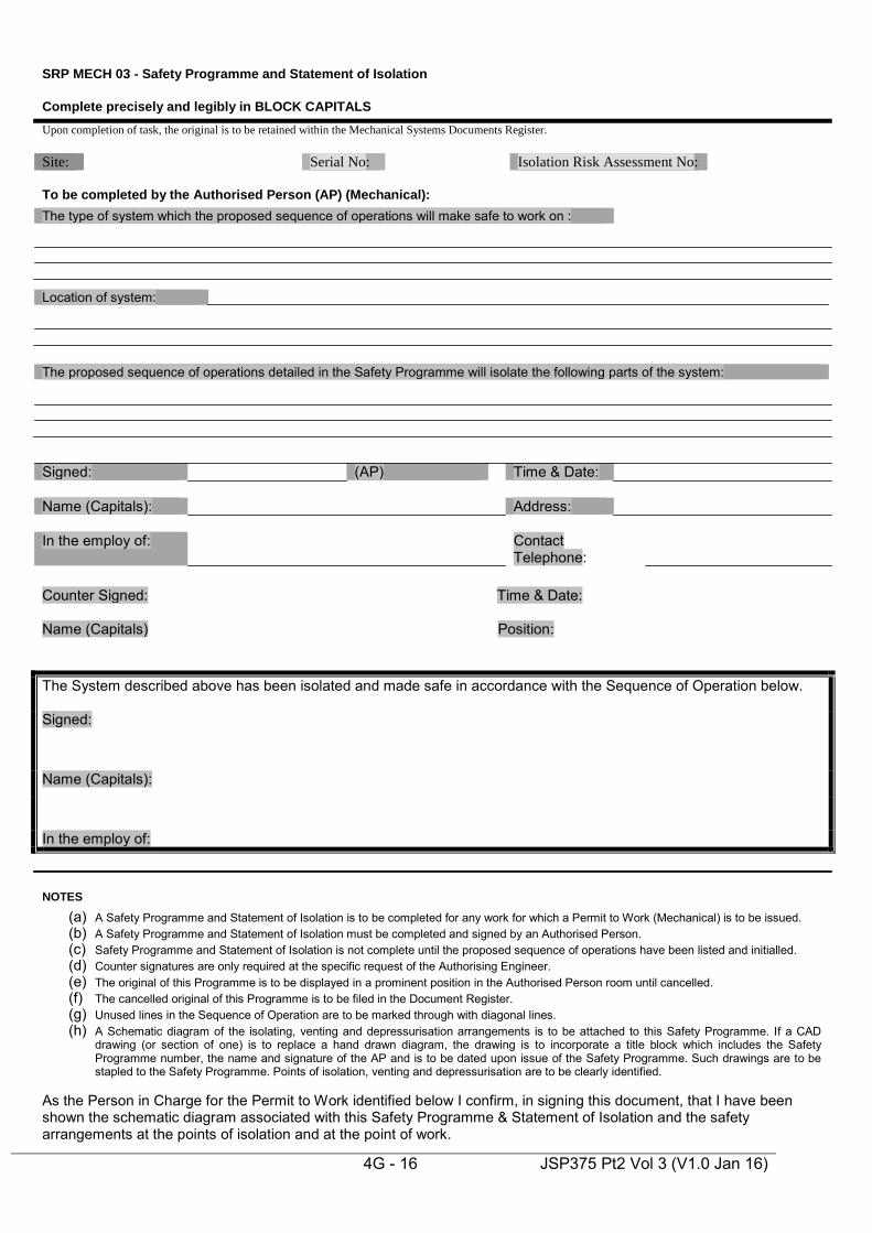
SRP MECH 03 - Safety Programme and Statement of Isolation
Complete precisely and legibly in BLOCK CAPITALS Upon completion of task, the original is to be retained within the Mechanical Systems Documents Register. Site: Serial No: Isolation Risk Assessment No:
4G - 16 JSP375 Pt2 Vol 3 (V1.0 Jan 16)
To be completed by the Authorised Person (AP) (Mechanical): The type of system which the proposed sequence of operations will make safe to work on :
Location of system:
The proposed sequence of operations detailed in the Safety Programme will isolate the following parts of the system: Signed: (AP) Time & Date: Name (Capitals): Address: In the employ of: Contact
Telephone:
Counter Signed: Time & Date: Name (Capitals) Position:
The System described above has been isolated and made safe in accordance with the Sequence of Operation below. Signed:
Name (Capitals):
In the employ of:
NOTES
(a) A Safety Programme and Statement of Isolation is to be completed for any work for which a Permit to Work (Mechanical) is to be issued. (b) A Safety Programme and Statement of Isolation must be completed and signed by an Authorised Person. (c) Safety Programme and Statement of Isolation is not complete until the proposed sequence of operations have been listed and initialled. (d) Counter signatures are only required at the specific request of the Authorising Engineer. (e) The original of this Programme is to be displayed in a prominent position in the Authorised Person room until cancelled. (f) The cancelled original of this Programme is to be filed in the Document Register. (g) Unused lines in the Sequence of Operation are to be marked through with diagonal lines. (h) A Schematic diagram of the isolating, venting and depressurisation arrangements is to be attached to this Safety Programme. If a CAD
drawing (or section of one) is to replace a hand drawn diagram, the drawing is to incorporate a title block which includes the Safety Programme number, the name and signature of the AP and is to be dated upon issue of the Safety Programme. Such drawings are to be stapled to the Safety Programme. Points of isolation, venting and depressurisation are to be clearly identified.
As the Person in Charge for the Permit to Work identified below I confirm, in signing this document, that I have been shown the schematic diagram associated with this Safety Programme & Statement of Isolation and the safety arrangements at the points of isolation and at the point of work.
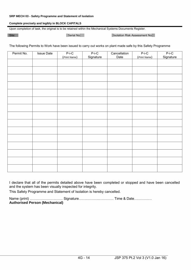
SRP MECH 03 - Safety Programme and Statement of Isolation
Complete precisely and legibly in BLOCK CAPITALS
Upon completion of task, the original is to be retained within the Mechanical Systems Documents Register. Site: Serial No: Isolation Risk Assessment No:
4G - 14 JSP 375 Pt.2 Vol 3 (V1.0 Jan 16)
The following Permits to Work have been issued to carry out works on plant made safe by this Safety Programme
Permit No. Issue Date P-i-C (Print Name)
P-i-C Signature
Cancellation Date
P-i-C (Print Name)
P-i-C Signature
I declare that all of the permits detailed above have been completed or stopped and have been cancelled and the system has been visually inspected for integrity. This Safety Programme and Statement of Isolation is hereby cancelled.
Name (print) ………………….…… Signature…….………..………… Time & Date…………… Authorised Person (Mechanical)
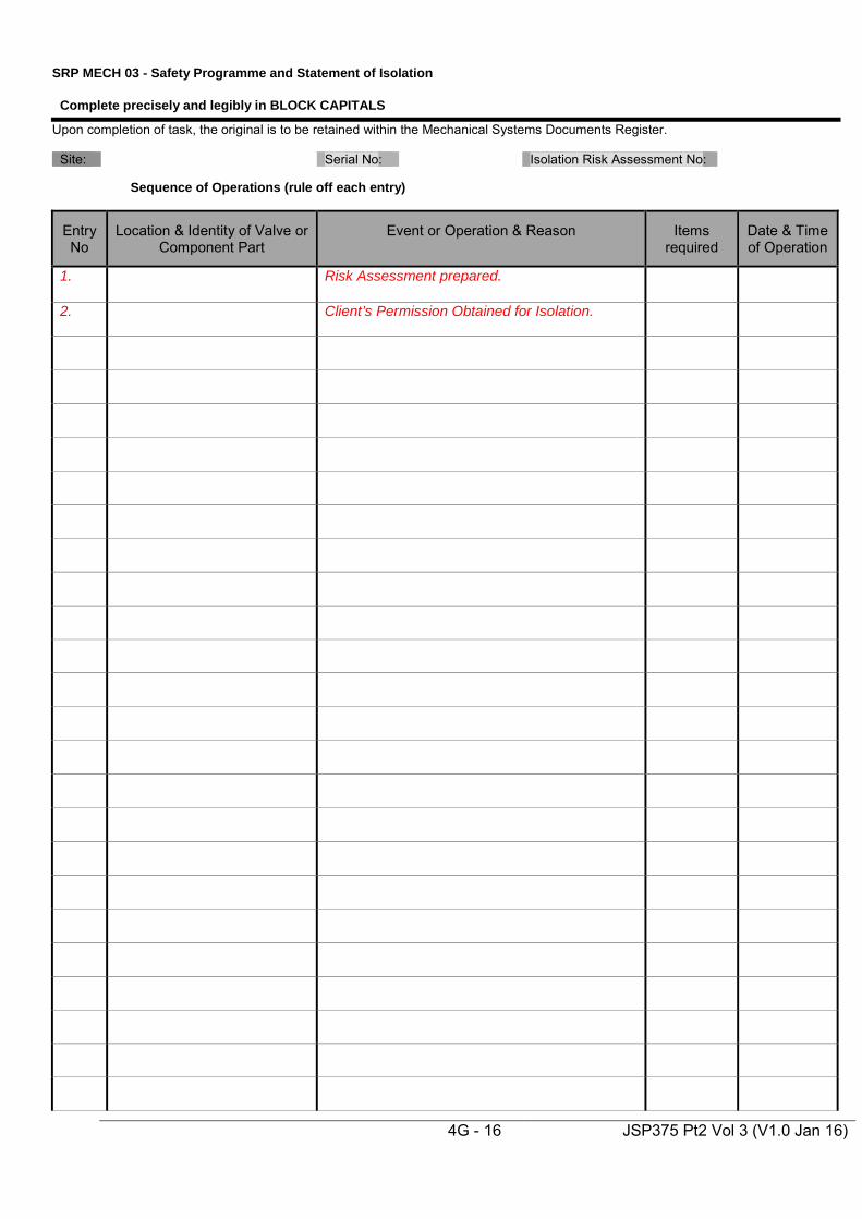
SRP MECH 03 - Safety Programme and Statement of Isolation
Complete precisely and legibly in BLOCK CAPITALS
Upon completion of task, the original is to be retained within the Mechanical Systems Documents Register.
Site: Serial No: Isolation Risk Assessment No:
4G - 16 JSP375 Pt2 Vol 3 (V1.0 Jan 16)
Sequence of Operations (rule off each entry)
Entry No
Location & Identity of Valve or Component Part
Event or Operation & Reason
Items required
Date & Time of Operation
1.
Risk Assessment prepared.
2.
Client’s Permission Obtained for Isolation.
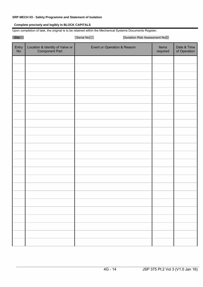
SRP MECH 03 - Safety Programme and Statement of Isolation
Complete precisely and legibly in BLOCK CAPITALS
Upon completion of task, the original is to be retained within the Mechanical Systems Documents Register.
Site: Serial No: Isolation Risk Assessment No:
4G - 14 JSP 375 Pt.2 Vol 3 (V1.0 Jan 16)
Entry No
Location & Identity of Valve or Component Part
Event or Operation & Reason
Items required
Date & Time of Operation

SRP MECH 04 - Permit to Work
Permit to Work Mechanical (Original)
4G - 16 JSP375 Pt2 Vol 3 (V1.0 Jan 16)
Site Serial No.
System Location Part 1 Authorisation The system has been isolated under Statement of Isolation No……………...……… I confirm that the issue of this Permit to Work has been recorded on the Statement of Isolation which is on display at …………………………………………………………………………………………….. The works to be carried out are as follows …………………………………………..……………….…… ………………………………………………………………………………….……………………………...… …………………………………………………………………………………………………………………………………………………………………………………………………………………………………………………………………………………………………………………………………………………………..……………………………………………………………………………………………………………………………………………………………………………………………………………………………………………Serial number of related Permit to Work ……………..……………………………………………...…… I am in receipt of and have reviewed the Task Risk Assessment No ……….. including the control measures and the task method statement.
Name (print) ………………….…… Signature…….………..………… Time & Date…………… Authorised Person (Mechanical) Contact Telephone Number……………………. Part 2 Acceptance I accept responsibility for carrying out the works detailed in Part 1. I have reviewed the Isolation Risk Assessment; I have reviewed & signed the Statement of Isolation; I have been shown all aspect of the isolation: I have applied a Safety Lock to the Safety Key Box and have retained the key. I am in receipt of and have reviewed the Task Risk Assessment No ……….. including the control measures and the task method statement and confirm that no attempt will be made by me or any person under my control to work on any other part of the system and that all persons under my control will work in compliance with the task risk assessment and method statement.
Name (print) ………………….…… Signature…….………..………… Time & Date…………… Person in Charge (Mechanical) Contact Telephone Number……………………. Part 3 Completion I declare that all persons, equipment, tools and instruments under my control have been withdrawn and that the works detailed in Part 1 have been:
*(a) satisfactorily completed.
*(b) stopped and abandoned, and that the system has been made safe pending further works, the reasons for stopping the work and the actions taken are detailed overleaf.
Name (print) ………………….…… Signature…….………..………… Time & Date…………… Person in Charge (Mechanical) I declare that the works detailed in Part 1 have been completed/stopped* and that the permit is cancelled. The entry relating to this permit on the Statement of Isolation has been signed as closed
Name (print) ………………….…… Signature…….………..………… Time & Date…………… Authorised Person (Mechanical)
* Strikethrough as appropriate
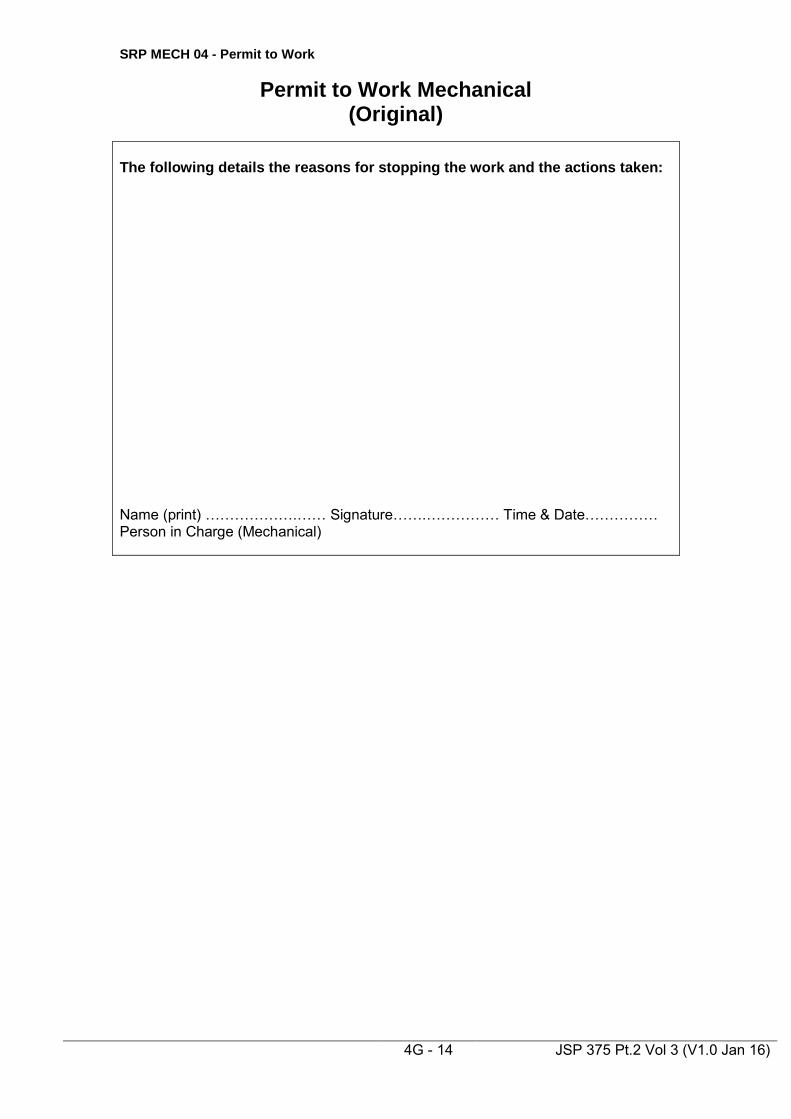
SRP MECH 04 - Permit to Work
Permit to Work Mechanical (Original)
4G - 14 JSP 375 Pt.2 Vol 3 (V1.0 Jan 16)
The following details the reasons for stopping the work and the actions taken:
Name (print) ……………….…… Signature…….…………… Time & Date…………… Person in Charge (Mechanical)

SRP MECH 05 - Standing Instruction
4G - 16 JSP375 Pt2 Vol 3 (V1.0 Jan 16)
STANDING INSTRUCTION for MECHANICAL SYSTEMS
Serial No.
Establishment To: ………………………………………….. (Person in charge) Employed by: …………………………………….. Issue Date: …………… Expiry Date (for repetitive tasks only): ……………….
Location and type of system to which
this instruction applies: ………………………………………………………………. Tasks to be undertaken on the system specified above: 1) …………………………………………………………………………………..
2) …………………………………………………………………………………..
3) …………………………………………………………………………………..
4) …………………………………………………………………………………..
Special instructions or safety measures: WORK CAN ONLY COMMENCE ON THE SYSTEM WHEN ALL OF THE ABOVE CONDITIONS HAVE BEEN MET. Signed: ……………………………….. (Originating Authorised Person) Name (CAPITALS): ………………………… Time & Date …………………………… In the employ of: ………………………….. Contact Tel No. ………………………
I acknowledge receipt of this Standing Instruction have been shown the system to which this Instruction refers and confirm that I fully understand the tasks listed above and the circumstances under which they are to be undertaken. Signed: …………………………….(Person in Charge) Name (CAPITALS): …………………………… Time & Date: ……………………………. Contact Tel No: …………………………… I hereby declare that: i) the work has been completed (for one off tasks only) ii) this Standing Instruction is cancelled iii) the original instruction has been lost. iv) the cancellation or loss has been noted in the Systems Operating Record Signed: …………………………………….. (Authorised Person) Name (CAPITALS): …………………………….. Time & date ……………………………. In the employ of: ……………………………… Contact Tel No. ……………………….

SRP MECH 06 – DAVS Permit to Work
4G - 17 JSP375 Pt2 Vol 3 (V1.0 Jan 16)
Dental Air and Vacuum Systems Permit to Work (Original)
Site Serial No. Part 1 Authorisation The system to be isolated is as follows …………………………………………………………... ……………………………………………………………………………………….………………... ……………………………………………………………………………………….………………... The works to be carried out are as follows ………………………………………..…………….. ………………………………………………………………………………….……………………... ………………………………………………………………………………………………………...
Name (print) …………………...…… Signature…….……….…….…… Date/Time…………… Authorised Person (Mechanical)
I acknowledge that the dental compressed air/vacuum* installation located in surgery ……………………………… will be taken out of service for a period of …………………….. hours/days from ……………………….. (date & time) to enable alterations/maintenance works to be carried out as detailed above. I confirm that I am responsible for the surgery named above and that I will inform all users of the dental installation named above of these works and their intended duration.
Signature………………………………….. Name (print) ……………………………….
Date……………………………….………. Time ………………………………………… Part 2 Acceptance I accept responsibility for carrying out the works detailed in Part 1. No attempt will be made by me or any person under my control to work on any other part of the system.
Name (print) …………………...…… Signature…….……….…….…… Date/Time…..……… Competent Person (MGPS) Part 3 Completion I declare that the works detailed in Part 1 have been completed and tested in accordance with the standards required. Test Certificate Serial No ………………….
Name (print) …………………...…… Signature…….……….…….…… Date/Time…………… Competent Person (MGPS)
I declare that the works detailed in Part 1 have been completed to my satisfaction. The installation has/has not* passed the required quality tests and can/can not* be returned to service.
Name (print) …………………...…… Signature…….……….…….…… Date/Time…………… Authorised Person (Mechanical) Part 4 Acceptance of System Back into Service I declare that all aspects of the works have been explained to me, including any modifications since the original instructions were approved at Part 1 above. I hereby accept the system back into service and will undertake to advise all the appropriate staff that the system has been re-instated.
Signature………………………………….. Name (print)……………………………
Date……………………………….………. Time…………………………………… * delete as necessary

SRP MECH 06 – DAVS Permit to Work
4G - 16 JSP375 Pt2 Vol 3 (V1.0 Jan 16)
The test results obtained are *Satisfactory/Not Satisfactory. The system *May/May Not be returned to service. Name (Print) _____________________Company__________________________ Signature__________________________Date___________Time_____________ * Delete as applicable.

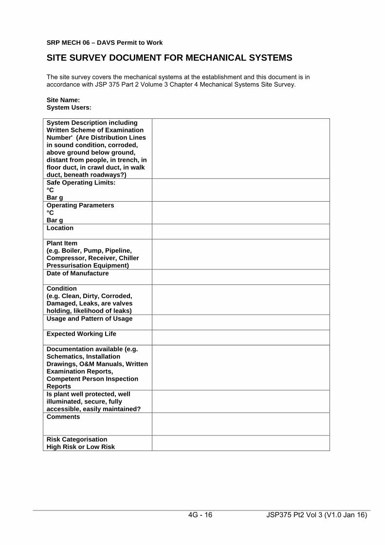
SRP MECH 06 – DAVS Permit to Work
4G - 16 JSP375 Pt2 Vol 3 (V1.0 Jan 16)
SITE SURVEY DOCUMENT FOR MECHANICAL SYSTEMS The site survey covers the mechanical systems at the establishment and this document is in accordance with JSP 375 Part 2 Volume 3 Chapter 4 Mechanical Systems Site Survey. Site Name: System Users: System Description including Written Scheme of Examination Number' (Are Distribution Lines in sound condition, corroded, above ground below ground, distant from people, in trench, in floor duct, in crawl duct, in walk duct, beneath roadways?)
Safe Operating Limits: °C Bar g
Operating Parameters °C Bar g
Location
Plant Item (e.g. Boiler, Pump, Pipeline, Compressor, Receiver, Chiller Pressurisation Equipment)
Date of Manufacture
Condition (e.g. Clean, Dirty, Corroded, Damaged, Leaks, are valves holding, likelihood of leaks)
Usage and Pattern of Usage
Expected Working Life
Documentation available (e.g. Schematics, Installation Drawings, O&M Manuals, Written Examination Reports, Competent Person Inspection Reports
Is plant well protected, well illuminated, secure, fully accessible, easily maintained?
Comments
Risk Categorisation High Risk or Low Risk