3d fitting simulation of glasses frames using …art-science.org/nicograph/disk/2010i/paper/s5-3...
TRANSCRIPT
3D Fitting Simulation of Glasses Frames Using Individual’s Face Model
Noriaki TAMURA and Katsuhiro KITAJIMA
Tokyo University of Agriculture and Technology, Tokyo, Japan
E-mail: [email protected], [email protected]
Abstract This paper proposes a novel 3D simulation method of wearing glasses frames that fits an individual’s face. The
method is based on our face modeling technique that can quickly generate an individual’s face polygon model with
sufficient accuracy from several pieces of image of a digital camera. In the optician’s shops, 2D simulators based
on the image composition of a face and glasses frames are widely used at both real optician’s shops and virtual shops.
Although 3D simulators have recently been put on the market, little of them are actually used. The main reason is
that it is difficult to generate 3D individual’s face models rapidly and in low cost. We solved both problems by
applying our 3D face modeling technique which we call the Generalized Free-Form Deformation (GFFD) method.
Moreover, in most of conventional 3D simulators, there is such a problem that glasses frames do not fit one’s face
because the frames in standard size are just located on the standard position. So, users can not be satisfied with the
visual effect of such simulators. We also solved this problem by newly developing a 3D fitting simulator to make
glasses frames fit an individual’s face. We achieved this by formulating the fitting (adjustment) procedure that is
actually conducted by skilled operators at real optician’s shops and then developed a novel method to automatically
scale and deform the glasses frames in standard shape and size into the frames that fit the face.
Keywords: glasses, glasses frames, individual’s face model, fitting simulation, GFFD
1. Introduction
Simulators of wearing glasses frames are widely used at
both real optician’s shops and virtual shops through the
Internet. The biggest advantage of using them is that
customers can virtually put various types of glasses frames on
and can watch their own faces wearing them, even though they
are not kept in the real shops.
3D simulators of wearing glasses frames have recently been
put on the market [1]. Most of simulators used now are,
however, not 3D, but 2D [2, 3, 4]. The main reason why the
conventional 3D simulators have never become popular is that
they need special expensive devices such as laser scanners and
grating pattern projection scanners. Moreover, at real shops,
it is necessary to quickly generate an individual’s face model
every time a new customer comes to the shops. So, the
authors solved the former problem by using digital cameras as
input devices, and the latter one by applying our 3D face
modeling technique which we call the Generalized Free-Form
Deformation (GFFD) method [5] to our simulator of wearing
glasses frames.
The main advantage of 3D simulators compared to 2D ones
is that the face wearing frames can be watched from various
directions. However, in conventional 3D simulators, it often
occurs that the nose pad or the temple of frames usually
intersect or do not touch the face when it is watched from
various directions. This reason is that the most of
conventional 3D simulators has such a problem that glasses
frames do not fit one’s face because the frames in standard size
are just located on the standard position and never be adjusted.
When we purchase glasses at real optician’s shops, the shop’s
operator adjusts frames’ temples, nose pads, etc. to the face so
that the frames fit the face untightly and unloosely. This
adjustment operation is called ‘fitting’ [6]. By formulating
this fitting operation, we have developed a 3D simulator of
wearing glasses frames that fits frames to individual’s face
models.
2. Geometric Model of Frames and Faces
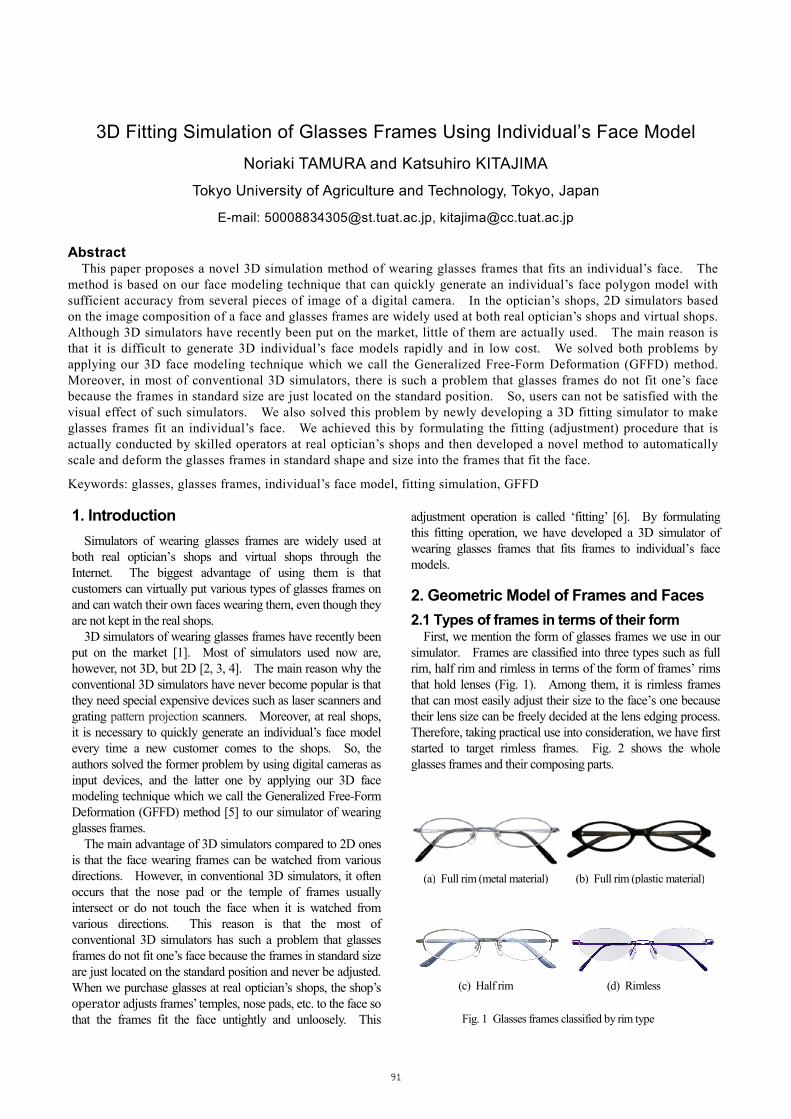
2.1 Types of frames in terms of their form First, we mention the form of glasses frames we use in our
simulator. Frames are classified into three types such as full
rim, half rim and rimless in terms of the form of frames’ rims
that hold lenses (Fig. 1). Among them, it is rimless frames
that can most easily adjust their size to the face’s one because
their lens size can be freely decided at the lens edging process.
Therefore, taking practical use into consideration, we have first
started to target rimless frames. Fig. 2 shows the whole
glasses frames and their composing parts.
(a) Full rim (metal material) (b) Full rim (plastic material)
(c) Half rim (d) Rimless
Fig. 1 Glasses frames classified by rim type
91

2.2 Geometric model of frames The frames consist of 17 parts. The geometric model for
each part is a triangle polygon. The authors made it from
standard size real frames by 3D modeling software.
2.3 Geometric model of faces As mentioned in 1.introduction, we generate individual’s
face models by using our GFFD method.
It first extracts feature points from the face images of three
views and computes their 3D coordinates. Then, it
transforms a generic face model which we generated as a
polygon model in advance to the individual’s face model by
treating the feature points as the control points of the GFFD
and deforming the space. The method makes it possible to
generate an individual's face model rapidly with sufficient
accuracy without any special expensive devices.
Fig. 3 shows the coordinate system that the face model is
defined. We define the frontal plane, the sagittal plane and
the horizontal plane that are used in the facial restoration
method of forensic medicine as x-y, y-z and z-x plane,
respectively. Then the point that three planes intersect is
determined as the origin.
In the next chapter, we will mention the method of frames
fitting simulation using the models of both frames and faces.
3. Method of Frames Fitting Simulation
3.1 Positioning the frames for a face (Preprocessing) In order to transform the frames’ parts models so that the
whole frames fit a face, we first decide the method of setting
the frames on the face at the position that they are worn. One
of the authors knows how the skilled operators at real optician's
shops set the frames. The process is as follows:
First, we locate the center of frames on the y-z plane of the
face (Fig. 4(a)). Next, we lean the frames so that the angles
between their lenses and the x-y plane will be 10 degrees (Fig.
4(b)). Then, we decide the position of y direction of the
frames so that the center of the lens will be 2mm below the
center of the pupil (Fig. 4(c)). The value 2mm, which is
called ‘eye point height’, is usually adopted at the most of
optician’s shops. Finally, we decide the position of z
direction so that the distance between the lens back and the
center of the pupil will be 12mm (Fig. 4(d)).
(a) Glasses frames
Fig. 2 Name of parts composing glasses flames
(b) Parts
Nose Pad Pad Arm
Bridge
Lens Endpiece
Temple
Screw
Tip Screw
Fig. 3 Coordinate system representing a face model
Frontal plane (x-y plane)
Sagittal plane(y-z plane)
Horizontal plane(z-x plane)
Origin
・x
z
y
・・pupil
lens back surface
(d) Deciding z position
12mm
Fig. 4 Positioning frames to a face
pupil
・1
1
2mm
(c) Deciding y position
(a) Deciding x position
(b) Leaning frames
10 degrees
92

3.2 Bending pad arms and leaning nose pads along nose's shape
After preprocessing, nose pads do not touch the nose surface
but apart from it or might stick into it (Fig. 5).
By bending the pad arms and leaning the nose pads, we can
make the nose-contacting surfaces of the pads fit the nose.
The whole process is divided into the following Steps A, B.
Step A: Making the position of the nose-contacting surface
coincide with that of the nose surface
First, we designate a vertex P on the polygon near the center
of the nose-contacting surface. Next, we obtain the point Q
which is the cross point between the straight line of z direction
from P and the surface of the nose that should contact the nose
pad (Fig. 6). Then, we bend the pad arm by the angle λx
around the vector of x direction passing the point O so that P
will coincide with Q (Fig. 7). The angle λx is calculated as
follows:
, (1)
where (Px, Py, Pz) is the coordinate in a local coordinate system,
the origin of which is the point O.
At this point, the position of the nose-contacting surface
coincides with that of the nose surface, but their orientations
are different each other.
Step B: Making the orientation of the nose-contacting surface
coincide with that of the nose surface
In this step, we rotate the pad to make the orientation of the
nose-contacting surface coincide with that of the nose surface.
The rotating angle α and the vector A for the axis of
rotation (as shown in Fig. 8) are easily calculated using the
inner product and outer product of two vectors, as follows:
, . (2)
where M and N are the average normal vectors of all
faces on the nose-contacting surface of the pad and the nose
surface, respectively.
After Step B, the position of the points P and Q may slightly
change. So, we judge the distance |PQ| between P and Q.
When |PQ| becomes within a certain threshold value Td,
the whole process is over, otherwise it returns to Step A.
Fig. 9 and 10 show the results of the nose pad fitting
procedure for five face models.
)PP
P (cos)
PP
PQP (cos
2
z
2
y
z1
2
z
2
y
z1
+−
+
+= −−
xλ
(a) Not touching (b) Sticking
Fig. 5 Examples of nose pad not fitting nose
NM
Distance PQ
Q
P
N−
Fig. 6 Top view for frames and a face
Fig. 7 Bending a pad arm
Fig. 8 Rotating a nose pad
・
λλλλxxxx
Direction of rotation
O Bending point (Center of rotation)
・ Center of rotation
A : Axis of rotation
))(
(cos1
ΝM
NM
−•
−•= −α
)(
)(
NM
NMA
−×
−×=
93
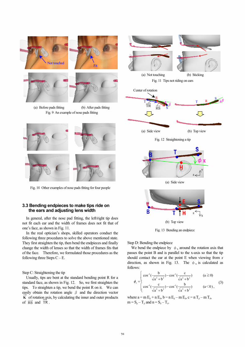
3.3 Bending endpieces to make tips ride on the ears and adjusting lens width
In general, after the nose pad fitting, the left/right tip does
not fit each ear and the width of frames does not fit that of
one’s face, as shown in Fig. 11.
In the real optician’s shops, skilled operators conduct the
following three procedures to solve the above mentioned state.
They first straighten the tip, then bend the endpieces and finally
change the width of lenses so that the width of frames fits that
of the face. Therefore, we formulated those procedures as the
following three Steps C – E.
Step C: Straightening the tip
Usually, tips are bent at the standard bending point R for a
standard face, as shown in Fig. 12. So, we first straighten the
tips. To straighten a tip, we bend the point R on it. We can
easily obtain the rotation angle β and the direction vector K of rotation axis, by calculating the inner and outer products
of RS and TR .
Step D: Bending the endpiece
We bend the endpiece by φx around the rotation axis that
passes the point B and is parallel to the x-axis so that the tip
should contact the ear at the point E when viewing from x
direction, as shown in Fig. 13. The φx is calculated as
follows:
(3)
where a = m Ey + n Ez, b = n Ey – m Ez, c = n Ty – m Tz,
m = Sy – Ty and n = Sz – Tz.
+−
+
+−
+=
−−
−−
,)0a()ba
b (cos)
ba
c (cos
)0a()ba
c (cos)
ba
b (cos
22
1
22
1
22
1
22
1
<
≧
xφ
Not touched Fit
(a) Before pads fitting (b) After pads fitting
Fig. 9 An example of nose pads fitting
Fig. 10 Other examples of nose pads fitting for four people
(a) Not touching (b) Sticking
Fig. 11 Tips not riding on ears
RT
ββββS
・TR
RS ・・ RT
S ββββ
・
Center of rotation
(a) Side view (b) Top view
Fig. 12 Straightening a tip
・ST
H
φφφφxxxx・・
・B
・ST
H
φφφφxxxx・・
・B
・
・
・
・・S
B H
E
T・
・
・
・・S
B H
E
T
Fig. 13 Bending an endpiece
y
z
x z
(b) Top view
(a) Side view
94
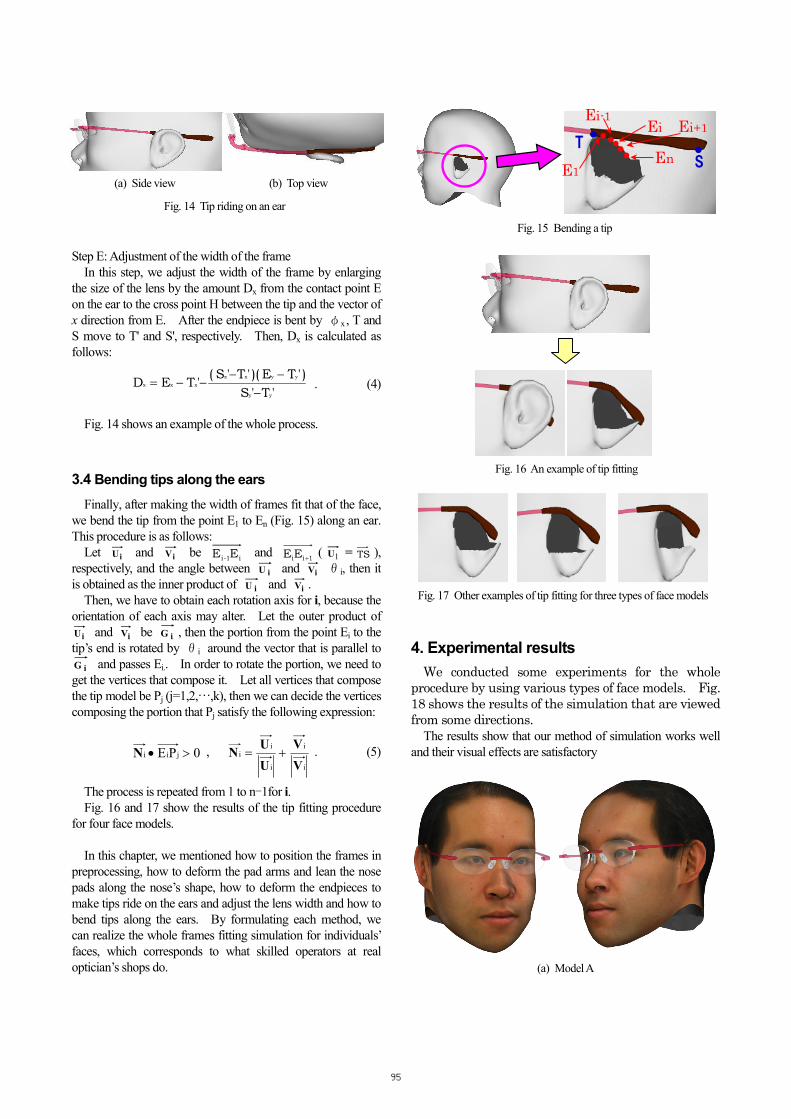
Step E: Adjustment of the width of the frame
In this step, we adjust the width of the frame by enlarging
the size of the lens by the amount Dx from the contact point E
on the ear to the cross point H between the tip and the vector of
x direction from E. After the endpiece is bent by φx , T and
S move to T' and S', respectively. Then, Dx is calculated as
follows:
. (4)
Fig. 14 shows an example of the whole process.
3.4 Bending tips along the ears
Finally, after making the width of frames fit that of the face,
we bend the tip from the point E1 to En (Fig. 15) along an ear.
This procedure is as follows:
Let iU and iV be i1-i EE and
1iiEE +( 1U = TS ),
respectively, and the angle between iU and iV θi, then it
is obtained as the inner product of iU and iV .
Then, we have to obtain each rotation axis for i, because the
orientation of each axis may alter. Let the outer product of
iU and iV be iG , then the portion from the point Ei to the
tip’s end is rotated by θi around the vector that is parallel to
iG and passes Ei.. In order to rotate the portion, we need to
get the vertices that compose it. Let all vertices that compose
the tip model be Pj (j=1,2,…,k), then we can decide the vertices
composing the portion that Pj satisfy the following expression:
, . (5)
The process is repeated from 1 to n-1for i. Fig. 16 and 17 show the results of the tip fitting procedure
for four face models.
In this chapter, we mentioned how to position the frames in
preprocessing, how to deform the pad arms and lean the nose
pads along the nose’s shape, how to deform the endpieces to
make tips ride on the ears and adjust the lens width and how to
bend tips along the ears. By formulating each method, we
can realize the whole frames fitting simulation for individuals’
faces, which corresponds to what skilled operators at real
optician’s shops do.
4. Experimental results
We conducted some experiments for the whole
procedure by using various types of face models. Fig.
18 shows the results of the simulation that are viewed
from some directions.
The results show that our method of simulation works well
and their visual effects are satisfactory
(a) Model A
'T'S
)'TE )('T'S ('TED
yy
yyxx
xxx
−−−
−−=
0PE jii >•N i
i
i
ii
V
V
U
UN +=
Fig. 14 Tip riding on an ear
(a) Side view (b) Top view
Fig. 15 Bending a tip
・・ ・・Ei
EnE1
Ei-1
・T
S・Ei+1・
Fig. 17 Other examples of tip fitting for three types of face models
Fig. 16 An example of tip fitting
95
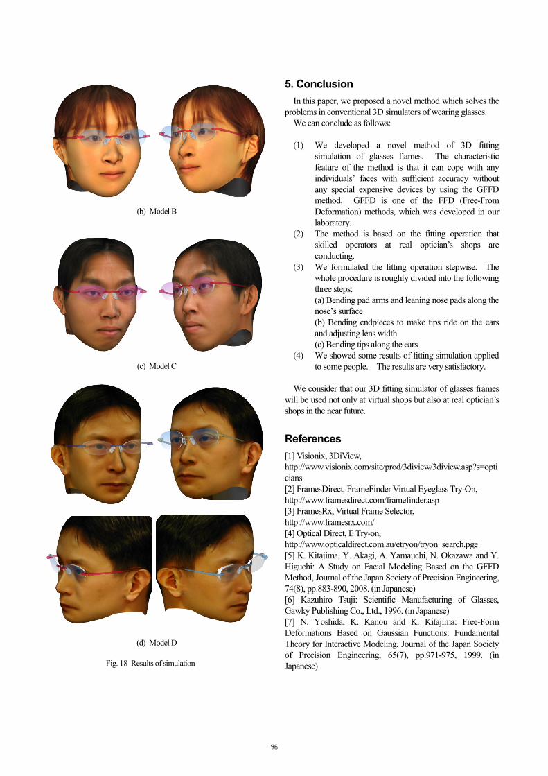
(b) Model B
(c) Model C
(d) Model D
5. Conclusion
In this paper, we proposed a novel method which solves the
problems in conventional 3D simulators of wearing glasses.
We can conclude as follows:
(1) We developed a novel method of 3D fitting
simulation of glasses flames. The characteristic
feature of the method is that it can cope with any
individuals’ faces with sufficient accuracy without
any special expensive devices by using the GFFD
method. GFFD is one of the FFD (Free-From
Deformation) methods, which was developed in our
laboratory.
(2) The method is based on the fitting operation that
skilled operators at real optician’s shops are
conducting.
(3) We formulated the fitting operation stepwise. The
whole procedure is roughly divided into the following
three steps:
(a) Bending pad arms and leaning nose pads along the
nose’s surface
(b) Bending endpieces to make tips ride on the ears
and adjusting lens width
(c) Bending tips along the ears
(4) We showed some results of fitting simulation applied
to some people. The results are very satisfactory.
We consider that our 3D fitting simulator of glasses frames
will be used not only at virtual shops but also at real optician’s
shops in the near future.
References
[1] Visionix, 3DiView,
http://www.visionix.com/site/prod/3diview/3diview.asp?s=opti
cians
[2] FramesDirect, FrameFinder Virtual Eyeglass Try-On,
http://www.framesdirect.com/framefinder.asp
[3] FramesRx, Virtual Frame Selector,
http://www.framesrx.com/
[4] Optical Direct, E Try-on,
http://www.opticaldirect.com.au/etryon/tryon_search.pge
[5] K. Kitajima, Y. Akagi, A. Yamauchi, N. Okazawa and Y.
Higuchi: A Study on Facial Modeling Based on the GFFD
Method, Journal of the Japan Society of Precision Engineering,
74(8), pp.883-890, 2008. (in Japanese)
[6] Kazuhiro Tsuji: Scientific Manufacturing of Glasses,
Gawky Publishing Co., Ltd., 1996. (in Japanese)
[7] N. Yoshida, K. Kanou and K. Kitajima: Free-Form
Deformations Based on Gaussian Functions: Fundamental
Theory for Interactive Modeling, Journal of the Japan Society
of Precision Engineering, 65(7), pp.971-975, 1999. (in
Japanese)
Fig. 18 Results of simulation
96