396 3790y1 - support.surefireag.com
TRANSCRIPT

396-3790Y1 QuickStart Setup Instructions for Raven RCM and NH3 Profile 02/22/2021 ©2017-2021 SureFire Ag Systems, Inc. — All Rights Reserved 1
396-3790Y1 QuickStart setup instructions for Raven RCM and SureFire harness for NH3 Profile with Liquid
Harness 213-00-3816Y1 and possibly others
Below are typical SureFire System setup screens for NH3 plus Liquid. Your setup may vary.
Read the Raven RCM Operation Manual for safety information and additional setup/operating information.
1. Navigate to the Setup Wizard
Rates Setup Setup
NH3 is a very dangerous product. It can kill you or blind you or worse. If you have not taken an
approved NH3 Safety Class, do not work around it. If you have had the course, follow ALL safety
precautions ALL the time. Applicator Setup
System Settings
Alarm Settings
2. Start a New Profile. 3. Enter a Profile Name. Machine Type > NH3 Tool 4. Number of Products = 2
You will see this icon
at times. Be patient. If using a hydraulic pump with a pump RPM sensor.
5.Select Application Type. 6.Set up Section Groups (example shows 3 sections for NH3 and liquid).
Sections 1-6 are reserved for NH3. Liquid will start with Section Driver 7.
1.6.2.5 or higher

396-3790Y1 QuickStart Setup Instructions for Raven RCM and NH3 Profile 02/22/2021 ©2017-2021 SureFire Ag Systems, Inc. — All Rights Reserved 2
QuickStart setup instructions for Raven RCM and SureFire NH3 Use with SureFire adapter harness: 213-00-3816Y1 NH3 Profile plus Liquid
7. Set up Pressure Sensors. Sensors 1 & 2 are reserved for NH3. Sensor 3
will be for Liquid. The example shows 1 sensor for NH3 and 1 for Liquid.
Choose “Custom” for SureFire
pressure sensors.
Normally, do not set any Pressure
Alarms. Pressure Alarms become
control limits on a liquid system.
Set RPM if using a hydraulic
pump with a pump RPM sensor
for the liquid product.
In this setup that would be Prod-
uct 2.
8.Set up Fan/Spinner RPM.
Use this if running a liquid hydraulic pump with an RPM sensor.
9.Set up Control Valve, Rate Sensor, Tank, and Rates for Product 1—NH3
Use 340 when using flowmeter
that is 144 pls/gal. Verify in field.
OPTIONAL: Use as desired.
Must enter at least 1 rate.
Check Display Smoothing.
Set Off Rate Alarm as desired.
340
500

396-3790Y1 QuickStart Setup Instructions for Raven RCM and NH3 Profile 02/22/2021 ©2017-2021 SureFire Ag Systems, Inc. — All Rights Reserved 3
QuickStart setup instructions for Raven RCM and SureFire NH3 Use with SureFire adapter harness: 213-00-3816Y1 NH3 Profile plus Liquid
10. Control Valve Setup—Start with these numbers. Adjust as needed in the field.
See Above
See at
Left
Low Limit (Adjust in field as needed)
PumpRight (hydraulic) 25
Tower (electric) 8
Catalyst and Spartan 5
PWM Startup (Adjust in field as needed)
PumpRight (hydraulic) 40
Tower (electric) 20
Catalyst and Spartan 5-10
Fine-tune PWM Low Limit at
Diagnostics > Tests > Calibrate
PWM Limits
11. Enter appropriate Flowmeter Cal
See below
Flowmeter
Size (GPM)
Pulses/
Gal
0.08-1.6 22710
0.13-2.6 3000
0.3-5.0 3000
0.6-13 2000
1.3-26 2000
2.6-53 2000
Spartan
model
#
Puls/
fl oz
115 1700
125 890
135 450
145 220
SureFire Electromagnetic Flowmeters.
Verify pls/gal on Serial Number label.
12(a). Tank and Fill Flowmeter set- 12(b). Fill Flowmeter Cal setup
OPTIONAL: Use as desired
Check Tank Fill Monitor box if
using a fill flowmeter.
13. Set Rates as desired.
You must enter at least one rate.
Check Display Smoothing
Set the Decimal Shift box at 1.
Set Decimal Shift at 2 for rates such
as 0.25 gal/ac.
14. Set Off-Rate Alarm as desired.
Read the Raven RCM Operation Manual for safety information and additional setup/operating information.
Then enter Tank Fill Flowmeter
Calibration
SFA 3” Fill Flowmeter 130
SFA 2” Fill Flowmeter 300
(Units are 10 gal on SureFire Tank
Fill flowmeters .)
OPTIONAL
Click on the Question Mark
for helpful information.
Valve Response Rate: For software 1.4 or higher (Adjust as needed in field)
PumpRight (hydraulic) 1
Tower (electric) 20
Catalyst and Spartan 5
Control Deadband: Start at 2
If pump is slow responding to rate or speed changes, increase Valve Response Rate If product oscil-lates around rate going across the field, reduce Valve Response Rate.
Electric Pumps will NOT use Ad-vanced Tuning with software 1.4 or higher.

396-3790Y1 QuickStart Setup Instructions for Raven RCM and NH3 Profile 02/22/2021 ©2017-2021 SureFire Ag Systems, Inc. — All Rights Reserved 4
QuickStart setup instructions for Raven RCM and SureFire NH3 Use with SureFire adapter harness: 213-00-3816Y1 NH3 Profile plus Liquid
15. Pressure Sensors must be calibrated. See the boxes below for the procedure. If you have 2 sensors, both must be
calibrated. Be sure there is no pressure against the sensor when calibrating. Unplug the sensor during the calibration
process. More on Pressure Sensor Diagnostics later. SureFire recommends putting the Pressure Sensor reading in
your Display Settings on the Run Screen (see next page). For
complete information on how the sensor is operating, go to
Diagnostics > System Information > Pressure Sensors.
0 Pressure Voltage should be 0.00 V.
Select Voltage-Based
Calibration
If you are using SureFire pressure sensors: CUSTOM
Pressure Sensor 1 (and 2 if using 2 NH3 sensors) is 0-5 v, 0-400 PSI, with 12.5 mv/PSI.
Pressure Sensor 3 is for the Liquid product and is a 0-5 v, 0-100 PSI sensor, with 50 mv/PSI.
Enter ‘12.5’ for NH3 sensor
Enter ‘50’ for Liquid Sensor
Read the Raven RCM Operation Manual for safety information and additional setup/operating information.
Diagnostics >
System Information
Menu
Diagnostics >
Tests
Menu
DIAGNOSTICS > SYSTEM INFORMATION and DIAGNOSTICS > TESTS
Go here for important system
information and to run system
tests.
For NH3
• Control Valve Test
• Energize System
• Bleed System Test
For Liquid
• Nozzle Flow Check
• Rinse Cycle
• Control / Section Test
• Calibrate PWM Limits
• Hardware / Software
• Switchbox
• Delivery System
• Section Status
• System Voltages
• Working Parameters
• Switches / Status
• Pressure Sensors
• Bin Level Sensors
• RPM Sensors
• Tank Fill Monitor
Product Summary
System Summary
ANHYDROUS AMMONIA IS AN INHALATION HAZARD AND WILL CAUSE SERIOUS INJURY
OR DEATH. PLEASE USE EXTREME CAUTION WHEN HANDLING IT OR PERFORMING ANY
MAINTENANCE ON EQUIPMENT USED FOR ANHYDROUS AMMONIA.

396-3790Y1 QuickStart Setup Instructions for Raven RCM and NH3 Profile 02/22/2021 ©2017-2021 SureFire Ag Systems, Inc. — All Rights Reserved 5
QuickStart setup instructions for Raven RCM and SureFire NH3
Display Setup Menu
Recommended for all Liquid systems
Recommended for hydraulic pump
systems with Pump RPM sensor
Run Screen Display Setup
Read the Raven RCM Operation Manual for safety information and additional setup/operating information.
Setup
Totals
Main
Diagnostics
Navigation
Implement Height Indicator Setup
Setup Applicator Setup
Check the Height Switch box if you are using a
Mercury Switch or Finger Style Switch for
Implement Height Indication.
Test Speed will be used later
when testing the system.
• Valve Response Rate
• Control Deadband
• PWM Setup (Coil Frequency, High Limit, Low
Limit, PWM Standby)
Control Valve Setup Menu
• RPM Calibration Pulse/Rev
• RPM Low Limit
• RPM High Limit
• RPM Sensor Assignment
Auxiliary Features Setup Menu
These 9 locations
can be edited from
Display Setup
Menu to show the
values you want to
see.

396-3790Y1 QuickStart Setup Instructions for Raven RCM and NH3 Profile 02/22/2021 ©2017-2021 SureFire Ag Systems, Inc. — All Rights Reserved 6
19. LIQUID Product Initial Operation in AUTO mode: (Could also do Nozzle Flow Check).
1. Enter a Test Speed by pressing on the Speed (mph) window or at Setup > Applicator Setup.
2. Toggle system to AUTO / ENABLED. Select a Rate.
3. Height switch must be DOWN (or uncheck Height Switch box).
4. Turn on Master Switch.
5. Monitor Actual Rate (gal/ac), Flow (gal/min), PSI, DC, Pump RPM.
6. Go to Switch Box (above). Turn Sections OFF and ON.
7. Turn Master Switch OFF. (NOTE: Pressure will be much less with water than with heavier, thicker fertilizer.)
18. LIQUID Product Initial Operation in MANUAL mode: (See Optional Manual Pump Operation below)
1. Fill the system with water. For first time startup, open air bleed valve until a steady stream comes out.
2. Enter a Test Speed by pressing on the Speed (mph) window or at Setup > Applicator Setup.
3. Navigate to MANUAL MODE as shown above (toggle between Auto and Manual with the Auto/Manual button).
4. ENABLE system (toggle between Enable / Disable with the Enable / Disable button).
5. Height switch must be DOWN (or uncheck Height Switch box).
6. Turn on Master Switch. Press and hold + to increase flow.
7. Monitor Flow (gal/min), PSI, DC, Pump RPM (if using Hydraulic pump with RPM sensor).
8. Go to Switch Box. Turn Sections OFF and ON.
9. Turn Master Switch OFF.
OPTIONAL MANUAL PUMP OPERATION:
Go to Diagnostics > Tests > Calibrate PWM LIMITS. Here you can manually run the pump without the system shutting
down if it doesn’t read flow immediately. Turn on Master Switch, Start the test, hold + button to increase pump speed.
Advanced Setup and Operating Information, Run Page, Initial Startup
AUTO MODE / DISABLED MANUAL MODE / DISABLED
AUTO MODE / ENABLED MANUAL MODE / ENABLED
If flow or pressure is not immediately detected, the Solution Pump Dry
warning will come up and the system will shut down.
Solution Pump Dry is NOT a problem for SureFire electric pumps or for
SureFire PumpRight hydraulic diaphragm pumps. It is a problem for
centrifugal pumps.
Read the Raven RCM Operator’s Manual for safety information and additional setup/operating information.
2

396-3790Y1 QuickStart Setup Instructions for Raven RCM and NH3 Profile 02/22/2021 ©2017-2021 SureFire Ag Systems, Inc. — All Rights Reserved 7
20. NH3 Initial Operation: FOLLOW ALL SAFETY PRECAUTIONS BEFORE TURNING ON ANHYDROUS AMMONIA
DIAGNOSTICS > TESTS for NH3 Product 1
1. Before opening nurse tank valve, check the operation of the control valve: Diagnostics > Tests > Product 1 >
Control Valve Test. Be sure the control valve is moving in the correct direction.
2. Before opening nurse tank valve, run Energize System Test to check the operation of the valves.
3. When safe to do so, slowly open the nurse tank valve. Running Energize System test will allow anhydrous ammonia
to escape. Be sure it is safe and wind is in the right direction before running this test. Read all safety precautions
before starting this test.
4. Bleed System Test will open the valves to empty the system. Close the nurse tank valve before running this.
5. Monitor amount applied with first tank or two and check the amount shown on the display against the weigh ticket
for the tank. Adjust flowmeter calibration as needed.
Running these tests may release NH3 into the air. Be sure that
is what you want to do and that it is safe to do so. Know the
wind direction. Follow all safety precautions. Every time.
SECTIONS 1-6
Imp Height Switch
POWER CONNECTOR
12 Pin ISO Connector
12 Pin ISO Connector
POWER CONNECTORSECTIONS 7-12
PRODUCT 2
25A
15A
15A
Dust cap
Plug in 201-3758Y1 with dust cap on 2-pin
Product 1 – NH3
Middle 23-pin 213-00-3816Y1 for NH3 and one Liquid/Dry Product
Plug into matching connectors from Front
ISO Extension harness
Plug into ISO Terminator
Plug into Raven RCM.
396-3790Y1 QuickStart Setup Instructions for Raven RCM and NH3 Profile 02/22/2021 ©2017-2021 SureFire Ag Systems, Inc. — All Rights Reserved 8
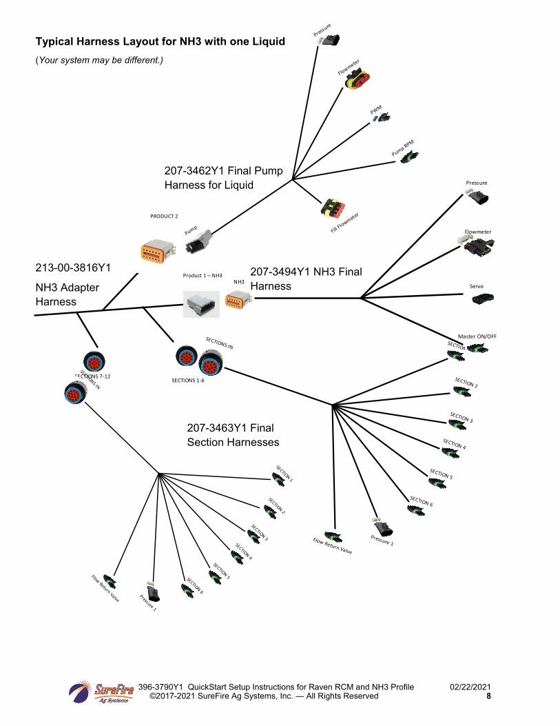
SECTIONS 1-6SECTIONS 7-12
PRODUCT 2
Product 1 – NH3
SECTION 1
SECTION 2
SECTION 3
SECTION 4
SECTION 5
SECTION 6
Pressure 1Flow Return Valve
SECTIONS IN
SECTION 1
SECTION 2
SECTION 3SECTION 4
SECTION 5SECTION 6Pressure 1
Flow Return Valve
SECTIONS IN
Pressure
Flowmeter
PWM
Pump RPM
Fill Flowmeter
Pump
Pressure
Flowmeter
Servo
Master ON/OFF
NH3
207-3462Y1 Final Pump
Harness for Liquid
207-3494Y1 NH3 Final
Harness
207-3463Y1 Final
Section Harnesses
213-00-3816Y1
NH3 Adapter
Harness
Typical Harness Layout for NH3 with one Liquid
(Your system may be different.)