37672-e0 residentialplumbing mg ed pr1 - lab-volt
TRANSCRIPT

Tech-Design
Residential Plumbing
Module Guide
Edition 1 37672-E0


FIRSTS EDITION
First Printing, April 2005
Copyright 2005 Lab-Volt Systems, Inc.
All rights reserved. No part of this publication may be reproduced, stored in a retrieval system, or transmitted in any form by any means, electronic, mechanical, photocopied, recorded, or otherwise, without prior written permission from Lab-Volt Systems, Inc. Information in this document is subject to change without notice and does not represent a commitment on the part of Lab-Volt Systems, Inc. The MultiMedia Tech-Design software and other materials described in this document are furnished under a license agreement or a nondisclosure agreement. The software may be used or copied only in accordance with the terms of the agreement.
ISBN-086657-664-9 Lab-Volt and Tech-Design are registered trademarks of Lab-Volt Systems, Inc. WindowsTM is a trademark of Microsoft Corp. Lead pipe photo courtesy of Roman Baths Museum, England. All other trademarks belong to their respective owners.

Lab-Volt License Agreement By using the software in this package, you are agreeing to become bound by the terms of this License Agreement, Limited Warranty, and Disclaimer. This License Agreement constitutes the complete agreement between you and Lab-Volt. If you do not agree to the terms of this agreement, do not use the software. Promptly return the multimedia (CD-ROM) compact discs and all other materials that are part of Lab-Volt's multimedia Tech-Design product within ten days to Lab-Volt for a full refund or credit. 1. License Grant. In consideration of payment of the license fee, which is part of the price you paid for this Lab-Volt product, Lab-Volt, as Licensor, grants to you, the Licensee, a nonexclusive, nontransferable license to use this copy of the CD-ROM software with the corresponding curriculum resources. Lab-Volt reserves all rights not expressly granted to the Licensee. 2. Ownership. As the Licensee, you own the physical media on which the CD-ROM is originally or subsequently recorded or fixed, but Lab-Volt retains title to and ownership of the software programs recorded on the original compact disc and any subsequent copies of the CD-ROM, regardless of the form or media in or on which the original and other copies may exist. This license is not a sale of the original software program of Lab-Volt's CD-ROM or any portion or copy of it. 3. Copy Restrictions. The CD-ROM software and the accompanying materials are copyrighted and contain proprietary information and trade secrets of Lab-Volt. Unauthorized copying of the CD-ROM even if modified, merged, or included with other software or with written materials is expressly forbidden. You may be held legally responsible for any infringement of Lab-Volt's intellectual property rights that is caused or encouraged by your failure to abide by the terms of this agreement. You may make copies of the CD-ROM solely for backup purposes provided the copyright notice is reproduced in its entirety on the backup copy. 4. Permitted Uses. This CD-ROM and all accompanying documentation is licensed to you, the Licensee, and may not be transferred to any third party for any length of time without the prior written consent of Lab-Volt. You may not modify, adapt, translate, reverse engineer, decompile, disassemble, or create derivative works based on the Lab-Volt product without the prior written permission of Lab-Volt. Written materials provided to you may not be modified, adapted, translated, or used to create derivative works without the prior written consent of Lab-Volt. 5. Termination. This agreement is effective until terminated. It will terminate automatically without notice from Lab-Volt if you fail to comply with any provisions contained herein. Upon termination you shall destroy the written materials, Lab-Volt's CD-ROM software, and all copies of them, in part or in whole, including modified copies, if any. 6. Registration. Lab-Volt may from time to time update the CD-ROM. Updates can be made available to you only if a properly signed registration card is filed with Lab-Volt or an authorized registration card recipient.
7. Miscellaneous. This agreement is governed by the laws of the State of New Jersey. Limited Warranty and Disclaimer This CD-ROM software has been designed to assure correct operation when used in the manner and within the limits described in the Tech-Lab® Multimedia Installation & User’s Guide. As a highly advanced software product, it is quite complex; thus, it is possible that if it is used in hardware configurations with characteristics other than those specified in Tech-Lab® Multimedia Installation & User’s Guide or in environments with non-specified, unusual, or extensive other software products, problems may be encountered by a user. In such cases, Lab-Volt will make reasonable efforts to assist the user to properly operate the CD-ROM but without guaranteeing its proper performance in any hardware or software environment other than as described in the Tech-Lab® Multimedia Installation & User’s Guide. This CD-ROM software is warranted to conform to the descriptions of its functions and performance as outlined in the courseware documentation. Upon proper notification and within a period of one year from the date of installation and/or customer acceptance, Lab-Volt, at its sole and exclusive option, will remedy any nonconformity or replace any defective compact disc free of charge. Any substantial revisions of this product, made for purposes of correcting software deficiencies within the warranty period, will be made available, also on a licensed basis, to registered owners free of charge. Warranty support for this product is limited, in all cases, to software errors. Errors caused by hardware malfunctions or the use of non-specified hardware or other software are not covered. LICENSOR MAKES NO OTHER WARRANTIES OF ANY KIND CONCERNING THIS PRODUCT, INCLUDING WARRANTIES OR MERCHANTABILITY OR OF FITNESS FOR A PARTICULAR PURPOSE. LICENSOR DISCLAIMS ALL OBLIGATIONS AND LIABILITIES ON THE PART OF LICENSOR FOR DAMAGES, INCLUDING BUT NOT LIMITED TO SPECIAL OR CONSEQUENTIAL DAMAGES ARISING OUT OF OR IN CONNECTION WITH THE USE OF THE SOFTWARE PRODUCT LICENSED UNDER THIS AGREEMENT. Questions concerning this agreement and warranty and all requests for product repairs should be directed to Lab-Volt field representative in your area. LAB-VOLT SYSTEMS, INC. P.O. Box 686 Farmingdale, NJ 07727 Attention: Program Development Phone: (732) 938-2000 or (800) LAB-VOLT Fax: (732) 774-8573 Technical Support: (800) 522-4436 Technical Support E-Mail: [email protected]

Residential Plumbing Table of Contents
Module Guide i
Welcome to Residential Plumbing!.............................................................................. 1
Introduction to Residential Plumbing.......................................................................... 3
Plumbing Basics ........................................................................................................ 4 The Water Supply System ......................................................................................... 5 The Drain, Waste, and Vent System.......................................................................... 6 Safety......................................................................................................................... 8 Pipe Comparison Chart.............................................................................................. 9
Residential Plumbing Trainer..................................................................................... 11
Lesson 1 – Install Sink Basket Strainers and Drain Assembly................................. 13 Lesson 2 – Install Tub Drain/Overflow and Trap...................................................... 19 Lesson 3 – Rough In the Drainpipe.......................................................................... 23 Lesson 4 – Install a Vent/Soil Stack and Cleanout................................................... 28 Lesson 5 – Rough In the Supply Pipes .................................................................... 31 Lesson 6 – Install a Kitchen Faucet ......................................................................... 34 Lesson 7 – Troubleshoot a Lavatory Faucet............................................................ 40 Lesson 8 – Install Shower Faucets .......................................................................... 44 Lesson 9 – Install a Showerhead and Tub Spout .................................................... 54 Lesson 10 – Install a Hose Bib ................................................................................ 58 Independent Study Projects..................................................................................... 63
Reference A – Tools and Fittings............................................................................... 65
Reference B – How to Measure Plastic Pipe............................................................. 67
Reference C – Blow-Up Diagrams.............................................................................. 69
Tub Drain/Overflow Assembly ................................................................................. 69 Generic – No Trip Lever........................................................................................... 69 Center Tee Drain Assembly..................................................................................... 70 Basket Strainer Assembly........................................................................................ 71

Residential Plumbing Table of Contents
ii Module Guide

Residential Plumbing Welcome to Residential Plumbing
Module Guide 1
WELCOME TO RESIDENTIAL PLUMBING! Welcome to the new Tech-Design Residential Workshop Series! The modules in this series are titled “Residential Plumbing,” “Residential Wiring,” and “3D Design and Construction Modeling.” These modules offer hands-on experiences in residential design, as well the techniques used to install the most common plumbing and electrical fixtures. It is likely that you will someday become a homeowner, and at some point, you’ll almost certainly find yourself in need of a common repair or upgrade. Homeowners spend a lot of money to hire craftspeople to do the same jobs you'll learn in this module. Regardless of whether or not you pursue one of these fields professionally, you will benefit enormously from the skills you acquire in these lessons. What if you had the ability to do your own plumbing and electrical wiring? The possibilities are endless. There are plenty of job opportunities for talented craftspeople in the areas covered in the Residential Workshop Series. Take renovation and construction, for example. Renovation has become a large percentage of construction in this country. Imagine the enormous satisfaction a carpenter gets after restoring the facade1 of a stylish Victorian home, along with all the details of its original design. Whether you enroll in a union apprenticeship program or learn by doing, a career in some aspect of residential construction, plumbing, or electrical wiring can be very rewarding. You may even decide to go into business for yourself. If you work hard and have patience and determination, your business can be a success!
1 facade - the front or face of a building.

Residential Plumbing Welcome to Residential Plumbing
2 Module Guide

Residential Plumbing Introduction to Residential Plumbing
Module Guide 3
INTRODUCTION TO RESIDENTIAL PLUMBING If you think of plumbing as being a network of pipes that provide the home with fresh water and drainage, you're right; but that’s just part of the complete picture. Let's take a brief look at a few interesting facts about plumbing. The early Romans constructed aqueducts (canals) to bring water to their cities from many miles away. Hot water baths, steam systems, fountains, and continuously flushing toilets were commonplace. Drains and sewer systems were built to carry away the dirty water. Later, the Romans began making pipe out of lead. In fact, the term "plumber" is derived from the Latin term "plumbus," which means lead. Complicated networks of lead pipes moved water from one place to another using gravity. Keep in mind that all this was engineered about two thousand years ago, long before gravity was discovered! Why a Plumber? You may ask yourself, "Why would I want to be a plumber?" The work is often difficult; but if you like working with tools and have sufficient problem-solving skills, this may be the profession for you. Being a licensed plumber can be very profitable. The author once had the opportunity to watch a residential plumber install a new hot-water heating system. He watched as pipes were run to and from the new furnace and hot-water heater. The plumber had a very good reputation and took pride in his work. When the plumbing inspector arrived, he thoroughly examined the finished product and
This lead pipe was made by hammering sheets of lead around a wooden pole.
Roman Aqueduct

Residential Plumbing Introduction to Residential Plumbing
4 Module Guide
then turned and said, “This is a work of art. These days, I rarely see anyone so meticulous about their work.” Being able to look back at what you've done and think, "I did that, and did it properly" can offer a great sense of accomplishment. If you think you may have an interest in the plumbing profession, you might consider this Module Guide an introduction to a career in residential plumbing. Plumbing Basics Our water sources vary according to where we live. Cities get their water from civically or privately owned water companies that treat and purify water collected from lakes, rivers, and reservoirs. If you live in the country, water is commonly obtained from wells. Pipes and other plumbing materials must be strong, durable, and non-corrosive. Supply pipes must withstand the high pressures inherent in water supply systems. They are made from materials that will match or exceed the expected life of the homes in which they are installed. The array of pipes found in the home may seem complex when you first look at them; but it's really quite simple once you know the basics. Once you are able to identify the specific parts and understand what they do, you're on the road to having the skills to install and maintain a home plumbing system. Water is provided by a municipal water company or by a well. In cities and towns, water runs through main supply lines under the street. A pipe branching off the main supply line enters the house and passes through a water meter and main shut-off valve. The water meter monitors the amount of water being used. The pipe then branches off to a water heater and from there, to all the fixtures and appliances in the house. Drain lines collect water from sinks, showers, and bathtubs. A strainer is used to prevent a sink or tub drain from clogging. Waste lines carry wastes from toilets. Because the drain and waste lines rely on gravity, they slope slightly downward, allowing the waste to run down and out to the municipal sewer or septic tank. Vent pipes allow sewer gases to escape and also allow wastes to flow freely by maintaining the necessary air pressure. Vent pipes are vital to drain and waste systems. If you have ever pressed your finger against the top of a straw and then pulled it out of a soda can, then you may have noticed how this created a vacuum and prevented the soda from running out of the straw. This would also happen if there were no vent pipes in a drain or waste system.

Residential Plumbing Introduction to Residential Plumbing
Module Guide 5
The Water Supply System The water supply pipes carry hot and cold water to all parts of the house. Hot and cold water pipes are run through walls or the underside of floor joists. Pipes that run through outside walls may freeze and burst in cold climates.
Most homes built within the last 40 years have copper supply pipes. Although copper is still the best material available, CPVC2 is slowly gaining acceptance. Codes vary and some areas may not allow plastic pipe. You should first check with your local building authority about codes, regulations, and inspections. Water supply pipes have small diameters, usually ranging from one-half to one inch. For a one-bathroom house, you need a minimum diameter of ¾-inch (1.91 cm) pipe for incoming cold water. The size needed for a specific water supply system is found in the state codebook, which is available from your local building inspector’s office. Based upon the beginning water pressure, it will describe the proper water pipe diameter according to the number of fixtures in the house and the furthest fixture from the water meter.
2 CPVC – chlorinated polyvinyl chloride

Residential Plumbing Introduction to Residential Plumbing
6 Module Guide
All pipes are joined with watertight fittings. Hot and cold water pipes are run side-by-side to faucets, tubs, showers, and other fixtures and appliances where both hot and cold water are required. Only cold water pipes are needed for toilets, fountains, and hose bibs.3 The most common appliances that require plumbing are dishwashers and washing machines. The Drain, Waste, and Vent System Also known as the DWV system, the drain, waste, and vent system is the network of large-diameter pipes that carry water and waste to the sewer or septic system. Vent pipes promote quick and efficient drainage. Large diameters are needed to minimize the possibility of blockages. Drainpipes typically range in diameter from 1½ to 4 inches (3.81 to 10.16 cm). 4-inch pipe is seldom seen in new home construction because it is too wide for long, horizontal runs. Generally, a 3-inch (7.62 cm) pipe is a soil pipe used for carrying solids while 1½- and 2-inch (5.08 cm) pipes are used to carry water from sinks, tubs, and washing machines. Drainpipes are sloped to allow the drain water to run down and out to the municipal sewer system or septic tank. The amount of slope depends upon the diameter of the pipe and its intended purpose. The standard guideline is at least ¼-inch (.64 cm) of drop for every foot of run. Plastic drainpipes (ABS or PVC) are almost universally accepted by plumbing codes. Older homes may have lead; but cast iron and copper are more common. Some of the older vent pipes are made of galvanized iron. Drains used for toilets, sinks, and bathtubs incorporate a trap, which is a curved section of pipe that holds standing water. This water prevents sewage gases from entering the house. Each time one of these fixtures is used, the water in the trap is replaced with fresh water. Waste lines should have cleanouts4 to allow easy access in case of a clog. Cleanouts are often seen as Y-shaped fittings that are capped off. Plumbing codes require a cleanout at the end of every horizontal drainpipe.
3 hose bib – a cold water spout with threads to accommodate a hose. 4 cleanout – a threaded cover on a waste pipe or trap that allows access for cleaning.

Residential Plumbing Introduction to Residential Plumbing
Module Guide 7
Vent pipes have two purposes. They allow air to circulate freely in the drainage system, which allows the water to flow freely down the drainpipes. They also allow sewer gases to escape through the roof. Proper ventilation is mandatory; therefore, you will never see a drainage system without vent piping. To save on materials and to avoid penetrating the roof more than once, the vent lines are tied together and run into one main vent stack, which is the pipe you usually see sticking up out of the roof of a house. In the figure above, notice that each horizontal run of drainpipe has a cleanout. Also notice that the drainpipes are sloped so that drain-water runs downward to the soil stack. The soil stack is connected to a sewer pipe, which runs out to the street or septic tank.
Drain, Waste, Vent System

Residential Plumbing Introduction to Residential Plumbing
8 Module Guide
Safety The guidelines in local plumbing codes ensure that a job is done in a way that protects the safety of the occupants of a home or building. An inspector checks the job to make sure that these guidelines are followed. There are a few general rules that you should always remember when working on a plumbing task: • Safety glasses should be worn during any soldering, cutting, or threading operation.
They should also be worn if there is a possibility of drainage splashing into your eyes.
• The work area should be kept as clear as possible. • Always use the correct tools and equipment for the job. • Always wash your hands after working on any part of the drain system. There are also some general rules that should be followed when using the Residential Plumbing Trainer: • Never use a tool for anything other than its intended purpose. • The threads on some fixtures may have sharp edges. Use caution when handling
them. • Use common sense whenever you use any of the tools. There should never be an
occasion where excessive force is necessary. If there is, ask your instructor for assistance.

Residential Plumbing Introduction to Residential Plumbing
Module Guide 9
Pipe Comparison Chart This chart shows the various types of pipe that are available from plumbing supply stores or home centers. Before using any of these pipes, you should check your local plumbing codes. The people at the plumbing supply store are very knowledgeable and can give you good advice. All diameters refer to the inside diameter (ID).
General Info Lengths Common Uses Diameters Fitting
Methods Cutting Tools
Cast Iron 5'’ – 10'’ main DWV pipe 3"- 4"
banded neoprene couplings
soil pipe cutter or hacksaw
ABS (acrylonitrile
butadiene styrene)
10’ – 20’ or by linear ft.
DWV pipes, traps
1¼” – 1½” - 2” – 3”- 4”
solvent glue, ABS fittings
tubing cutter, hacksaw
PVC (polyvinyl chloride)
10’ – 20’ or by linear ft.
DWV pipes, traps
1½” – 2”- 3” and 4”
solvent glue, PVC fittings
tubing cutter, hacksaw mitre saw
Galvanized Iron* various hot and cold
water, drains
½” - ¾” – 1” – 1½” - 2’
galvanized threaded fittings
pipe cutter, tubing cutter
CPVC (chlorinated
polyvinyl chloride)
10’ hot and cold
water 100psi
3/8” – ½” – ¾” – 1”
solvent glue, CPVC
fittings, grip fittings
tubing cutter, hacksaw, miter saw
PB (polybutylene)
25’ – 100’ coils or by linear ft.
hot and cold water (where
permitted) 3/8” - ½” - ¾” plastic grip
fittings
tubing cutter, hacksaw,
sharp knife
Rigid Copper 10’ – 20’ or by linear ft.
hot and cold water supply
3/8” - ½” - ¾” and 1”
solder , copper
fittings or compression
fittings
tubing cutter, hacksaw
Chromed Copper 12’ – 20’ –30’
tubing for fixture water
supply (visible when
installed)
3/8” brass
compression fittings
tubing cutter, hacksaw
Flexible Copper Tubing
30’ – 60’ coils or by linear ft.
hot and cold water supply, natural gas
¼ - 3/8” – ½” – ¾” – 1”
brass compression fittings, flare
fittings, solder
tubing cutter, hacksaw
Chromed Brass various valves, shutoffs, traps
¼” – ½” – ¾” for traps 1¼"–
1½"
compression fittings
tubing cutter, hacksaw
*Not recommended for new installations.

Residential Plumbing Introduction to Residential Plumbing
10 Module Guide

Residential Plumbing Residential Plumbing Trainer
Module Guide 11
RESIDENTIAL PLUMBING TRAINER
The Residential Plumbing trainer comes with a kitchen faucet, lavatory faucet, shower and tub fixtures, and all the pipes and fittings you'll need for the lessons in this manual. The knowledge and skills you'll gain from these experiences will enable you to install and maintain the most common fixtures found in residential plumbing. CPVC pipe is used instead of copper because of the risks associated with using a torch and solder. In many areas, plumbing codes consider CPVC to be an acceptable alternative for hot and cold water supply lines. We chose this material because it is much safer to work with and effectively demonstrates how hot and cold supply lines distribute water. You will also install drainpipes and fittings where needed. The glues that are made for PVC and CPVC are toxic and flammable. They should never be used without adequate ventilation. We cannot guarantee that the area where you'll be working will be properly ventilated; therefore, all pipes will be dry-fitted5. 5 dry-fit – to connect pipe without the use of glue.

Residential Plumbing Residential Plumbing Trainer
12 Module Guide
In the Reference section, photos are provided so that you can easily identify all of the tools and fittings used in these lessons. They'll also help you to become familiar with the correct terminology. This Module Guide contains photos to guide you through the steps you’ll be performing in each lesson. A video for each lesson is also provided and can be accessed on your computer. Your instructor will show you how to access these videos as well as your pretest, posttest, exercises, and lesson quizzes.
NOTE: Never over-tighten any of the parts and fixtures in these lessons. Everything must be disassembled so that other students can use them.

Residential Plumbing Residential Plumbing Trainer
Module Guide 13
Lesson 1 – Install Sink Basket Strainers and Drain Assembly When you have completed this lesson, you will be able to: • install sink basket strainers onto a predrilled sink platform. • install tailpieces to the sink drain. • install a center type, double drain assembly. • Install a drain trap. MATERIAL LIST 1 – 1½-in. PVC pipe 2 – 1½-in. PVC tailpiece w/washer (If needed) 1 – 1½-in. PVC drain trap 1 – 1½-in. Trap adapter 1 – Center type, double drain assembly 2 – Basket strainers Sanding cloth TOOLS YOU'LL NEED Channel-type pliers Hacksaw Felt-tipped marker Tape measure Safety goggles Bench vise Use the bench vise and wear safety goggles whenever you are cutting pipe. If necessary, refer to “How to Measure Plastic Pipe” in the Reference section for additional help. You may view a video of this activity by going to Lesson 1 on your computer. Click on the icon for the video titled “Install Sink Basket Strainers and Drain Assembly.” This video can be paused or repeated as often as necessary to complete this lesson. Identify each part of the strainer assembly. You should have the following parts:
• Basket strainer • Strainer body • Rubber and fiber washer • Locknut
NOTE: A blow-up diagram of the basket strainer assembly is provided in the Reference section.

Residential Plumbing Residential Plumbing Trainer
14 Module Guide
1. Normally, a bead of plumber's putty should be applied to the bottom of a strainer body flange prior to permanent installation. You will be dry-fitting the strainers because the installation is temporary. Begin by inserting the two strainer bodies through the pre-drilled sink drain holes.
2. While holding the strainer firmly in place, install the rubber washer and then the fiber washer (if included) over the neck of the strainer body. Screw the locknut onto the neck of the strainer and gently tighten it with channel-type pliers.
Install the other strainer by repeating Steps 1 and 2.
Residential Plumbing Residential Plumbing Trainer
Module Guide 15
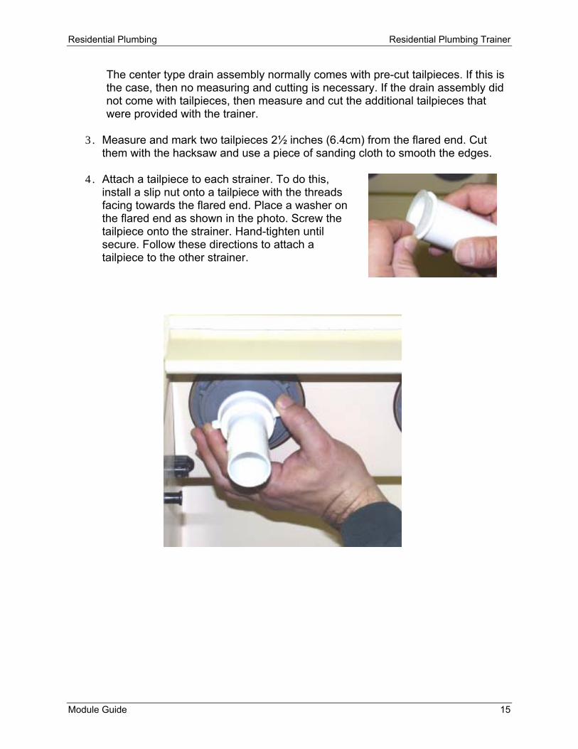
The center type drain assembly normally comes with pre-cut tailpieces. If this is the case, then no measuring and cutting is necessary. If the drain assembly did not come with tailpieces, then measure and cut the additional tailpieces that were provided with the trainer.
3. Measure and mark two tailpieces 2½ inches (6.4cm) from the flared end. Cut
them with the hacksaw and use a piece of sanding cloth to smooth the edges. 4. Attach a tailpiece to each strainer. To do this,
install a slip nut onto a tailpiece with the threads facing towards the flared end. Place a washer on the flared end as shown in the photo. Screw the tailpiece onto the strainer. Hand-tighten until secure. Follow these directions to attach a tailpiece to the other strainer.
Residential Plumbing Residential Plumbing Trainer
16 Module Guide
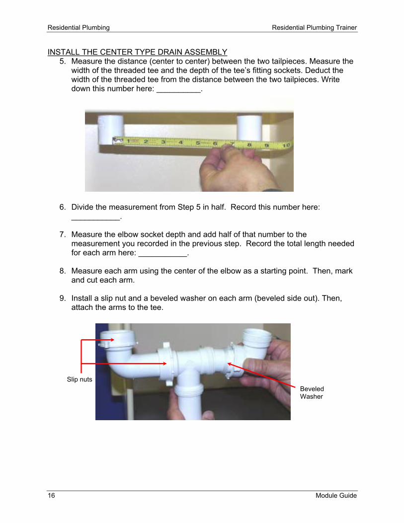
INSTALL THE CENTER TYPE DRAIN ASSEMBLY 5. Measure the distance (center to center) between the two tailpieces. Measure the
width of the threaded tee and the depth of the tee’s fitting sockets. Deduct the width of the threaded tee from the distance between the two tailpieces. Write down this number here: __________.
6. Divide the measurement from Step 5 in half. Record this number here: ___________.
7. Measure the elbow socket depth and add half of that number to the measurement you recorded in the previous step. Record the total length needed for each arm here: ___________.
8. Measure each arm using the center of the elbow as a starting point. Then, mark and cut each arm.
9. Install a slip nut and a beveled washer on each arm (beveled side out). Then, attach the arms to the tee.
Slip nuts Beveled Washer
Residential Plumbing Residential Plumbing Trainer
Module Guide 17
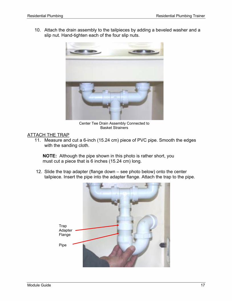
10. Attach the drain assembly to the tailpieces by adding a beveled washer and a slip nut. Hand-tighten each of the four slip nuts.
ATTACH THE TRAP
11. Measure and cut a 6-inch (15.24 cm) piece of PVC pipe. Smooth the edges with the sanding cloth.
NOTE: Although the pipe shown in this photo is rather short, you must cut a piece that is 6 inches (15.24 cm) long.
12. Slide the trap adapter (flange down – see photo below) onto the center tailpiece. Insert the pipe into the adapter flange. Attach the trap to the pipe.
Trap Adapter Flange
Pipe
Center Tee Drain Assembly Connected to Basket Strainers

Residential Plumbing Residential Plumbing Trainer
18 Module Guide
13. Tighten the trap coupling and the adapter locknut. Make sure all the other fittings are secure.
REMINDER: Traps are an essential part of sink and tub drains because they prevent sewage gases from entering the house.
The trap you attached to the sink drain will be connected to a drainpipe in another lesson. Congratulations! You've successfully installed the sink strainers and drain assembly. Go to the next section in the presentation, Exercise. When you are finished, read the Lesson Review and then take the Lesson Quiz. After you have taken the quiz, you may proceed to Lesson 2.

Residential Plumbing Residential Plumbing Trainer
Module Guide 19
Lesson 2 – Install Tub Drain/Overflow and Trap When you have completed this lesson, you will be able to:
• assemble the tub drain/overflow based on the directions supplied by the manufacturer.
• Install the tub drain/overflow assembly. • install a trap.
MATERIAL LIST Tub drain/overflow kit ½-inch PVC trap w/coupling 2 ft (61cm) 1½-inch PVC pipe 1½-inch trap adapter Sanding cloth TOOLS YOU'LL NEED Channel-type pliers Felt-tipped marker Tape measure Slotted and Phillips head screwdrivers Hacksaw Safety goggles Bench vise This tub drain has no linkage for a trip lever. This means that the tub drain stopper is opened and closed by hand instead of with a lever. Use the bench vise and wear safety goggles whenever you are cutting pipe. If necessary, refer to “How to Measure Plastic Pipe” in the Reference section for additional help. There is also a blow-up diagram of the drain overflow kit in the Reference section. You may view a video of this activity by going to Lesson 2 on your computer. Click on the icon for the video titled “Install Tub Drain/Overflow and Trap.” This video can be paused or repeated as often as necessary to complete this lesson. Your tub drain-overflow kit includes the following parts:
• Overflow cover plate • Adjustable height overflow pipe • Adjustable drain T-fitting with adjustable tailpiece • Drain cover plate with strainer-plunger

Residential Plumbing Residential Plumbing Trainer
20 Module Guide
1. Using the blow-up diagram (Reference C), assemble the pipes and attach all the gaskets and washers included in your tub drain/overflow kit.
2. On the center portion of the trainer, place the overflow elbow and rubber gasket
against the back of the overflow hole. Using the chrome-plated screws, attach the chrome cover plate to the overflow elbow.
3. For a permanent installation, a bead of plumber's putty would be placed around the underside of the drain piece/strainer flange. In this case, the strainer flange is dry-fit because the installation is temporary.
4. Extend the adjustable drain T-fitting until the drain elbow and gasket line up with
the hole for the drain.
NOTE: If the adjustable drain T-fitting does not reach the drain hole, then shorten the overflow tube accordingly.

Residential Plumbing Residential Plumbing Trainer
Module Guide 21
Rubber Washer
5. Insert the drain piece/strainer through the drain hole and screw it into the elbow with rubber washer underneath. Tighten until snug.
6. Using the channel-type pliers, gently tighten all slip nuts. Double-check your work.
NOTE: The previous steps should take place before the tub is installed.

Residential Plumbing Residential Plumbing Trainer
22 Module Guide
Adapter Flange (Pipe Hidden)
Drain T-Fitting Tailpiece
ATTACH THE TRAP
7. Measure and cut a 1-inch (2.5cm) piece of 1½-inch PVC pipe. Smooth the edges with the sanding cloth. NOTE: the trap adapter you install in Step 8 may be configured differently and may not require the 1-inch pipe that you just cut.
8. Slide the trap adapter (flange down) onto the drain T-fitting tailpiece. Insert the pipe into the adapter flange. Attach the trap to the trap adapter.
In the next lesson, the trap will be connected to a drainpipe. Good Job! You have successfully installed a tub drain and trap. Go to the next section in the presentation, Exercise. When you are finished, read the Lesson Review and take the Lesson Quiz. After you have taken the quiz, you may proceed to Lesson 3.

Residential Plumbing Residential Plumbing Trainer
Module Guide 23
Lesson 3 – Rough In the Drainpipe When you have completed this lesson, you will be able to: • determine where to position the waste T-fittings so that they can be connected to the
drain traps. • measure and cut PVC pipe so that the installed T-fittings can be connected to the
drain traps. • connect sink and tub drain traps to the drainpipe. MATERIAL LIST 1 – 5ft (1.5m) x 1½-inch PVC pipe 2 – 1½-inch PVC waste T-fittings 2 – 1½-inch PVC street elbows TOOLS YOU'LL NEED Hacksaw Tape measure Felt-tipped pen Safety goggles Bench vise Sanding cloth Use the bench vise and wear safety goggles whenever you are cutting pipe. For additional help, refer to “How to Measure Plastic Pipe” in the Reference section. You may view a video of this activity by going to Lesson 3 on your computer. Click on the icon for the video titled “Rough In the Drainpipe.” This video can be paused or repeated as often as necessary to complete the lesson.

Residential Plumbing Residential Plumbing Trainer
24 Module Guide
1. Connect a street elbow to the trap below the sink. The trap bend is now directed down to where the drainpipe will run.
2. Cut a 1-inch (2.5cm) piece of pipe. Use this to connect the waste T-fitting, with pipe attached, to the trap below the sink.

Residential Plumbing Residential Plumbing Trainer
Module Guide 25
3. The waste T-fitting for the sink should be facing in the direction shown in the photo below. The arrow indicates the direction that water runs, which is toward a vent/soil stack.
NOTE: Unlike vent pipes, waste pipes require gradual changes in direction, which is why waste T-fittings do not have a sharp bend. The direction that you want the drain water to flow determines the direction in which the waste T-fitting should be installed. Because you’ll want water to flow downward and to the right, the waste T-fitting should be installed accordingly.
4. Connect a street elbow to the drain trap below the tub. The drain trap will now
direct water down toward the drainpipe.
5. Measure and cut another piece of PVC pipe to use for connecting the tub drain trap to the waste T-fitting. Remember that if you have trouble, you can refer to “How to Measure Plastic Pipe” in the Reference section.
Street Elbow

Residential Plumbing Residential Plumbing Trainer
26 Module Guide
Connecting the tub drain trap to the existing pipe will require careful planning. Look at your job and try to determine where the trap should be installed. You must run more pipe to another waste T-fitting where the drain trap for the tub will be connected. Due to a lower tailpiece, the tolerances are closer below the tub drain than they were below the sink. So, take your time and try to get it right the first time.
6. Twist the upper drain trap elbow towards the left, so that both traps are angled toward each other. Connect the waste T-fitting to the drain trap.
7. Measure the gap between the two waste T-fittings and cut a piece of pipe accordingly. Remember to include the depth of the fitting sockets while calculating your next cut. Once again, refer to “How to Measure Plastic Pipe” in the Reference section if you have trouble.
8. Use the pipe to connect the two waste T-fittings.

Residential Plumbing Residential Plumbing Trainer
Module Guide 27
Step 8
Step 9
9. Cut a 1 ft (30.5cm) piece of pipe and attach it to the left side of the waste T-fitting. This pipe will extend out through the opening in the left panel.
REMINDER: Horizontal runs of drainpipe should drop ¼-inch (.635 cm) for every foot (30.5 cm) of run. You can determine how much downward slope is needed by multiplying the total length of drainpipe, in feet, by .25.
Congratulations! This portion of the DWV (Drain, Waste, Vent) system is now installed. At least one vent pipe will be added. Otherwise, water will not drain properly. Go to the next section in the presentation, Lesson Review. Read the review and then take the Lesson Quiz. After you have taken the quiz, you may proceed to Lesson 4.

Residential Plumbing Residential Plumbing Trainer
28 Module Guide
Lesson 4 – Install a Vent/Soil Stack and Cleanout When you have completed this lesson, you will be able to: • cut a piece of PVC pipe to use as a vent stack. • connect the vent sack to the waste cross. • connect the drainpipe to the waste cross. • connect another piece of drainpipe to the waste cross and then to a cleanout fitting. MATERIAL LIST 1 – 5ft (1.5 m) x 1½-inch PVC pipe 1 – 1½- inch waste cross 1 – Cleanout fitting w/threaded cap 1 – 1½-inch PVC elbow TOOLS YOU'LL NEED Hacksaw Tape measure Felt-tipped pen Safety goggles Bench vise Sanding cloth Use the bench vise and wear safety goggles whenever you are cutting pipe. For additional help, refer to “How to Measure Plastic Pipe” in the Reference section. Local codes specify the maximum distance that a drain trap can be from a vent pipe. In this case, the sink and tub drains are extremely close to one another, eliminating the need for additional vent pipes. In the home, however, these fixtures are much further apart. Separate trap vents would be installed and connected to the vent stack. Refer to the diagram in the section titled “The Drain, Waste, Vent System” to see where these vents are installed in a home. You may view a video of this activity by going to Lesson 4 on your computer. Click on the icon for the video titled “Install a Vent/Soil Stack and Cleanout.” This video can be paused or repeated as often as necessary to complete this lesson. The vent/soil stack will run vertically behind the shower fixtures.
1. Cut a 2ft (61 cm) piece of 1½-inch (3.8 cm) pipe and smooth the edges with the sanding cloth.

Residential Plumbing Residential Plumbing Trainer
Module Guide 29
2. Place the waste cross on the right, between the tub drain partitions. Lower the pipe through the hole next to the lavatory faucet. Connect the pipe to the waste cross fitting.
Waste Cross

Residential Plumbing Residential Plumbing Trainer
30 Module Guide
3. Measure the distance between the waste T-fitting below the tub drain and the waste cross. Cut the appropriate length piece of pipe and use it to connect the two fittings. If needed, refer to “How to Measure Plastic Pipe” in the Reference section for additional help.
Complete the DWV installation by installing a cleanout. Cleanouts make the DWV system easier to service.
4. Measure and cut another piece of pipe, at least 6-inches (15cm) long. Connect it to the waste cross.
5. Connect an elbow (1½-inch or 3.8 cm) to the end of the drainpipe and then
connect a cleanout to the elbow. Good job! You’ve successfully completed the DWV system. The sink and tub drains are fully installed and you also installed a vent pipe and a cleanout. Go to the next section in the presentation, Lesson Review and then take the Lesson Quiz. After you have taken the quiz, you may proceed to Lesson 5.

Residential Plumbing Residential Plumbing Trainer
Module Guide 31
Lesson 5 – Rough In the Supply Pipes When you have completed this lesson, you will be able to: • determine where T-fittings should be located for supplying hot and cold water to a
sink and shower faucets. • measure and cut ½ inch CPVC pipe to the appropriate lengths needed for supplying
water to a kitchen sink. • install a T-fitting for supplying hot and cold water to a hose bib. . • run pipe and install elbows for supplying hot and cold water to a shower valve. MATERIAL LIST 1 – 5ft (1.5m) x ½-inch CPVC pipe 2 – ½-inch CPVC T-fittings TOOLS YOU'LL NEED Hacksaw Tape measure Felt-tipped pen Safety goggles Bench vise Sanding cloth In this activity, you will run the hot and cold supply lines for a kitchen faucet, hose bib, and shower. Fittings will be installed so that these fixtures can be mounted and connected at a later time. Use the bench vise and wear safety goggles whenever you are cutting pipe. If needed, refer to “How to Measure Plastic Pipe” in the Reference section for additional help. You may view a video of this activity by going to Lesson 5 on your computer. Click on the icon for the video titled “Rough In the Supply Pipes.” This video can be paused or repeated as often as necessary to complete this lesson. INSTALL THE HOT WATER PIPE Look at where the kitchen faucet and shower faucets will be installed. Hot water faucets are always located on the left side. You will need a T-fitting for the faucet. You will also need to divert hot water for the shower. Since you cannot accurately determine placement of the elbows for the shower faucet water supply, we’ll come back to that after the shower faucets are installed.

Residential Plumbing Residential Plumbing Trainer
32 Module Guide
1. Cut a 4-inch (10cm) piece of pipe and connect it to a T-fitting. The T-fitting should be placed just below the hot water side of the kitchen faucet. The kitchen faucet will be mounted on the top panel with the four predrilled holes. The left hole will accommodate the hot water faucet.
2. Measure the distance from the T-fitting to directly below where the shower hot-
water faucet will be located (left hole on shower panel), then add 3-inches (8cm) to that measurement.
3. Cut a piece of CPVC pipe to the appropriate length. Smooth the edges with the sanding cloth.
4. Connect the pipe to the T-fitting and let it rest on the partition opening for the
shower. The pipe will be a few inches (appx. 8cm) too long, but this will be corrected later.
INSTALL THE COLD WATER PIPE Cold water faucets are always located on the right side. Once again, you’ll need a T-fitting for the cold water faucet, and a run of pipe across to the shower. In a different lesson, a hose bib will be installed midway between the kitchen faucet and the shower faucet, but we will ignore the cold water connection for now. The final location of the hot and cold water T-fittings is not critical. This is because the kitchen faucet will be connected to the water supply with flexible supply hoses.
5. Place a T-fitting directly below where the cold water faucet will be located.
6. Measure and cut a piece of pipe and connect it to the T-fitting. This pipe should be cut to a length so that it extends out through the partition wall at a distance equal to that of the hot water pipe.
Hot Water Pipe Ends 3 in (8cm) Beyond Hole Predrilled for Shower Hot Water

Residential Plumbing Residential Plumbing Trainer
Module Guide 33
7. Measure the distance from the T-fitting to directly below where the shower cold water faucet will be located, then add approximately 2-inches (5 cm) to that measurement.
NOTE: Both pipes will be removed and cut again when the shower faucets are installed.
8. Connect the pipe to the T-fitting. This pipe should run to the right end of the
trainer, beyond where the shower cold water faucet will be located.
REMINDER: Before using CPVC in your home, you should check your local plumbing code. In many areas, only copper is accepted.
REMINDER: The pipe diameter for the water supply is determined by the demand based on the amount of fixtures and the length of the supply lines.
Congratulations! The hot and cold water pipes are now installed and ready to supply water to the fixtures. Go to the next section in the presentation, Lesson Review and then take the Lesson Quiz. After you have taken the quiz, you may proceed to Lesson 6.
T-Fittings
Cold Water Pipe Extends All The Way Across

Residential Plumbing Residential Plumbing Trainer
34 Module Guide
Lesson 6 – Install a Kitchen Faucet When you have completed this lesson, you will be able to: • install a kitchen faucet. • connect flexible vinyl supply tubes to the faucet tailpieces. • install shut-off valves. MATERIAL LIST 1 – Single-handle kitchen faucet 2 – ½ x ⅜ Flexible vinyl supply tubes 2 – ½-inch CPVC male adapters 1 – Teflon tape 2 – Shutoff valves 2 – 2-inch (5cm) x ½-inch CPVC pipe TOOLS YOU'LL NEED Adjustable wrench Basin wrench Channel-type pliers Hacksaw Bench vise Safety goggles Sanding cloth Use the bench vise and wear safety goggles whenever you are cutting pipe. Installing a faucet is a simple operation. Regardless of the faucet’s style, its installation usually follows a standard set of directions. Sinks normally have four pre-drilled holes to accommodate a faucet and sprayer. If there are no holes in the sink, drilling is the first step in the process. All faucets come with either a template or a diagram that shows exactly where the holes should be placed if drilling is necessary. Since drilling is not necessary, you may begin installing your faucet. You may view a video of this activity by going to Lesson 6 on your computer. Click on the icon for the video titled “Install a Kitchen Faucet.” This video can be paused or repeated as often as necessary to complete this lesson.

Residential Plumbing Residential Plumbing Trainer
Module Guide 35
1. Run the sprayer hose through the sprayer base. Insert the sprayer hose into the hole farthest to the right. From below the sink, run the mounting nut through the hose and screw it onto the sprayer base.

Residential Plumbing Residential Plumbing Trainer
36 Module Guide
2. Wrap a small amount of Teflon tape around the tailpiece threads and the center spray hose nipple.
3. Install the faucet through the two outer holes on the faucet panel. The center hole is for the sprayer hose connection.
Normally, a bead of plumber’s putty or silicone caulk should be applied to the base of the faucet prior to mounting. This step is not needed because the installation is temporary.

Residential Plumbing Residential Plumbing Trainer
Module Guide 37
4. Install the mounting bracket on the threaded shank. Then, install the mounting nut and tighten by hand.
NOTE: Different faucet models may have different installation procedures. If your faucet has no threaded shank and it is mounted with two plastic locknuts, one for each tailpiece, then the basin wrench will not be necessary. Hand tightening is sufficient. A basin wrench has a long handle and is used for working in tight areas. See Reference A – Tools and Fittings.
5. Make sure the faucet is on straight by moving the faucet until the deck plate is parallel with the splashboard (rear panel). Using the basin wrench, tighten the mounting nut and tailpiece nuts (if provided).
6. Screw the spray hose onto the spray hose nipple and tighten it with the
adjustable wrench.
7. Attach the flexible supply tubes to the tailpieces and tighten them with the channel-type pliers.
Residential Plumbing Residential Plumbing Trainer
38 Module Guide
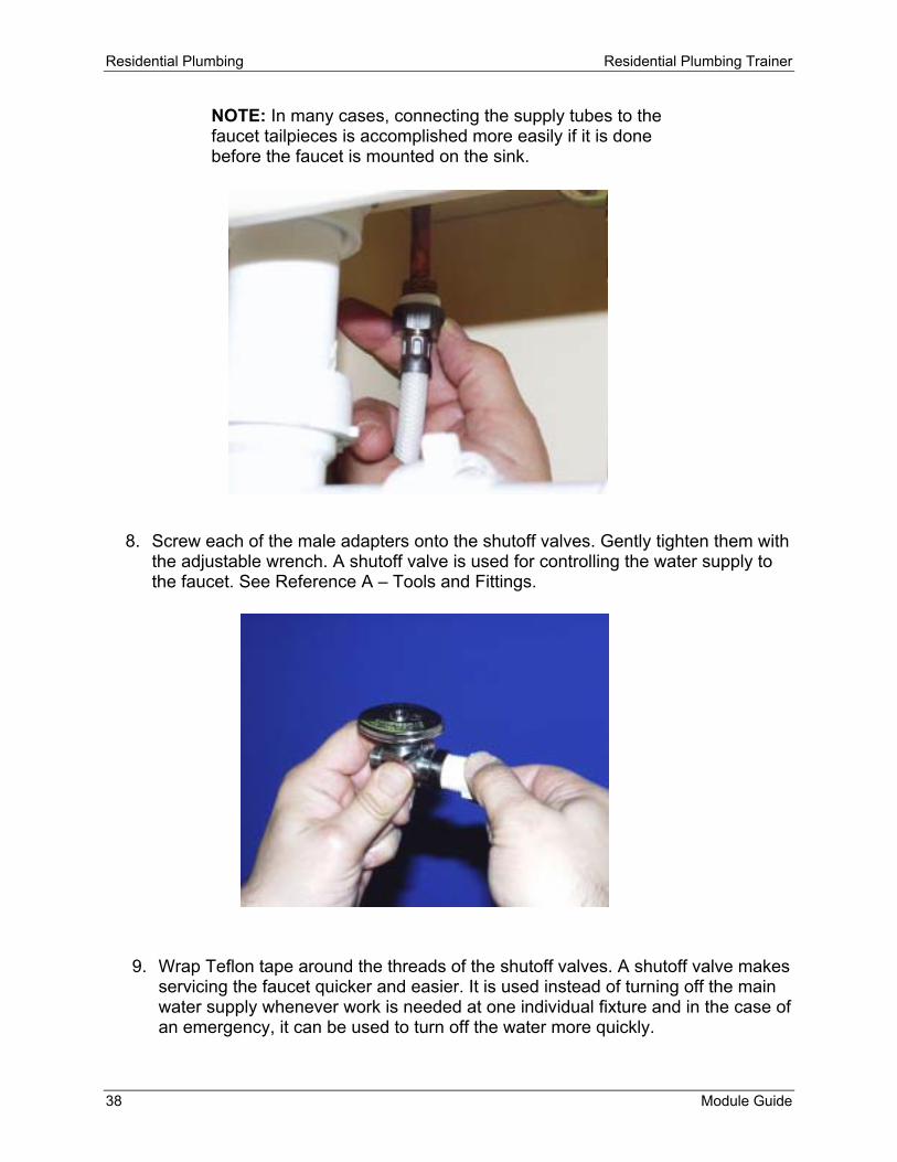
NOTE: In many cases, connecting the supply tubes to the faucet tailpieces is accomplished more easily if it is done before the faucet is mounted on the sink.
8. Screw each of the male adapters onto the shutoff valves. Gently tighten them with the adjustable wrench. A shutoff valve is used for controlling the water supply to the faucet. See Reference A – Tools and Fittings.
9. Wrap Teflon tape around the threads of the shutoff valves. A shutoff valve makes servicing the faucet quicker and easier. It is used instead of turning off the main water supply whenever work is needed at one individual fixture and in the case of an emergency, it can be used to turn off the water more quickly.

Residential Plumbing Residential Plumbing Trainer
Module Guide 39
10. Attach the water supply tubes to the shutoff valves.
11. Cut two 2-inch (5cm) pieces of ½-inch CPVC pipe. Smooth the edges with the sanding cloth.
12. Install each pipe between the T-fitting sockets and the male adapter sockets.
Congratulations! The faucet is now completely installed along with shutoff valves. Go to the next section in the presentation, Lesson Review and then take the Lesson Quiz. After you have taken the quiz, you may proceed to Lesson 7.

Residential Plumbing Residential Plumbing Trainer
40 Module Guide
Lesson 7 – Troubleshoot a Lavatory Faucet When you have completed this lesson, you will be able to: • remove the handle from a lavatory faucet. • remove the cartridge and examine the main features. • remove the seat and spring. • add a coat of faucet grease, if necessary. • reassemble a faucet. MATERIAL LIST Lavatory faucet Towel or rag Faucet grease TOOLS YOU'LL NEED Adjustable wrench Slotted and Phillips head screwdrivers Channel-type pliers A leaky faucet is one of the most common residential plumbing problems. In older faucets, this occurs when washers, O-rings, or seals become dirty or worn. In newer faucets, this is usually due to worn seats and springs or a worn cartridge. Before you begin this type of project, you must identify the type of faucet you have and determine which replacement parts you will need. This way, the replacement parts are available before the job is started. In this activity, you'll disassemble a cartridge-type faucet (the most commonly found on the market today); remove the cartridge, seat, and spring; and reassemble the faucet. Before beginning this type of project, you must always turn off the water supply! Close the shutoff valves or main service valve. You may view a video of this activity by going to Lesson 7 on your computer. Click on the icon for the video titled “Troubleshoot a Lavatory Faucet.” This video can be paused or repeated as often as necessary to complete this lesson.
1. Using a slotted screwdriver, carefully pry off the cap from one of the faucet handles. If it is threaded, unscrew it counterclockwise.

Residential Plumbing Residential Plumbing Trainer
Module Guide 41
2. Remove the handle screw that holds the faucet handle onto the stem spindle. Then, remove the handle by pulling straight up. Put the handle screw in a safe place.
3. Using the adjustable wrench, remove the cartridge-retaining nut by turning it counterclockwise.

Residential Plumbing Residential Plumbing Trainer
42 Module Guide
4. Using the channel type pliers, pull the cartridge out of the faucet body.
5. Using the Phillips screwdriver, carefully remove the seat and spring. If the spring is larger on one end than the other, make note of which end faces up.
If a cartridge faucet leaks, the seat and spring are the parts you’d be replacing. If the faucet continued to leak, the cartridge would also have to be replaced.
6. Using a towel, clean the faucet body.
7. Reinstall the seat and spring.

Residential Plumbing Residential Plumbing Trainer
Module Guide 43
8. Check the cartridge to see if it’s coated with a thin layer of lubricant. If the lubricant is almost gone, very lightly coat the cartridge with the faucet grease before reinstalling.
9. Looking down at the faucet body, you’ll see two notches. Align the cartridge with the notches and then push it into the faucet body.
10. Screw the retaining nut back on and hand tighten. Finish tightening with the adjustable wrench
11. Re-install the faucet handle and screw.
Nice work! Years ago, fixing a leaking compression faucet was simply a matter of replacing a washer and an O-ring. However, it often involved struggling with corroded screws and stripped valve stems. It was also common for the handle to seem like it was welded to the stem. A handle puller would be needed to remove the handle. Go to the next section in the presentation, Exercise. When you are finished with the exercise and have read the Lesson Review, complete the Lesson Quiz. When you have completed the lesson quiz, you may move on to Lesson 8.

Residential Plumbing Residential Plumbing Trainer
44 Module Guide
Lesson 8 – Install Shower Faucets When you have completed this lesson, you will be able to: • install shower faucets by first determining where the faucet body should be placed. • measure and cut appropriate lengths of pipe. • install drop elbows for a tub spout and showerhead. • install the faucet body. • mount faucet handles. MATERIAL LIST 1 – Two handle shower faucet kit 2ft (61cm) x ½-inch CPVC pipe 5 – ½-inch CPVC male adapter 2 – ½-inch brass/CPVC drop elbows 2 – ½-inch CPVC 90º elbows TOOLS YOU'LL NEED Adjustable wrench Phillips head screwdriver Hacksaw Felt-tipped pen Pencil Tape measure Safety goggles Bench vise Sanding cloth Use the bench vise and wear safety goggles whenever you are cutting pipe. At any time during the lesson, you can refer to “How to Measure Plastic Pipe” in the Reference section. You may view a video of this activity by going to Lesson 8 on your computer. Click on the icon for the video titled “Install Shower Faucets.” This video can be paused or repeated as often as necessary to complete this lesson. Before you begin, the outer shower panel must be removed. This panel has predrilled holes for the shower arm, shower faucets, and the tub spout.

Residential Plumbing Residential Plumbing Trainer
Module Guide 45
1. Using the screws provided, install a drop elbow on the lower portion of the shower panel. This elbow will be used to accommodate a tub spout.
NOTE: The CPVC insert should be facing up.
2. Screw a ½-inch (1.25cm) male adapter into the elbow. Tighten the adapter with an adjustable wrench.
You are now ready to install the shower faucet body.
Residential Plumbing Residential Plumbing Trainer
46 Module Guide
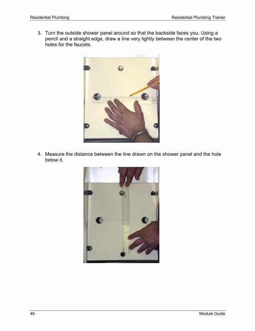
3. Turn the outside shower panel around so that the backside faces you. Using a pencil and a straight edge, draw a line very lightly between the center of the two holes for the faucets.
4. Measure the distance between the line drawn on the shower panel and the hole below it.

Residential Plumbing Residential Plumbing Trainer
Module Guide 47
5. Take a moment to look at each of the four fitting sockets on the faucet body (one on the left, two in the center, and one on the right). If they are threaded, then install a male adapter into each socket. If they are not threaded, then they will accommodate CPVC pipe without an adapter. Now, using your measurement from Step 4 and taking the depths of the fitting socket or male adapter into consideration, cut a piece of pipe the appropriate length, smooth out the edges, and insert it into the drop elbow. Place the lower faucet body discharge port onto the pipe.

Residential Plumbing Residential Plumbing Trainer
48 Module Guide
The center of the faucet body and faucet stems should line up properly with the two large holes in the outside shower panel. To verify this, temporarily press the shower panel against its mounting clips. The faucet stems should line up and protrude through the panel. If they don’t, then go back and make the necessary corrections.
6. Hold another drop elbow directly over the mounting holes on the top of the panel. The CPVC insert should be facing down.
7. Measure the distance between the drop elbow and the upper faucet body discharge port. Don’t forget to include the depth of the fitting sockets or male adapters. Cut and install another pipe while mounting the drop elbow using the bolts provided. The faucet body is now installed.

Residential Plumbing Residential Plumbing Trainer
Module Guide 49
NOTE: In the home, the shower faucets are normally 48 inches (1.2 m) high and the showerhead is 72 inches (1.8 m) high.
On the bottom of the faucet body are two supply ports for hot and cold water. You will now measure and cut the hot and cold water pipes so that they can be connected to the faucet body.

Residential Plumbing Residential Plumbing Trainer
50 Module Guide
8. Measure and cut a piece of pipe long enough to fit into the hot water supply port and extend about 1 inch beyond the hot water pipe you roughed in earlier. The two pipes should cross. Mark the hot-water pipe on the left side of the vertical pipe you are now holding.
9. Temporarily remove the hot water pipe from the trainer and cut it on the mark.
10. Reinstall the pipe and place an elbow on the end.
Mark Here

Residential Plumbing Residential Plumbing Trainer
Module Guide 51
11. Measure and cut the vertical pipe to the appropriate length and place it in the hot water supply port. Connect the other end to the elbow.
12. To connect the cold water pipe to the faucet supply port, repeat the procedures described in Steps 7 through 11. When the hot and cold water is connected, it should look like the photo shown here.

Residential Plumbing Residential Plumbing Trainer
52 Module Guide
13. Install the outer shower panel. 14. Place an escutcheon on each faucet valve. 15. If your faucet came with chrome hubs, install
them now. 16. Using a Phillips screwdriver, attach the faucet
handles. Press the caps onto the faucet handles.
Good job! The shower faucets are now completely installed. Knowing the fitting dimensions and socket depth is a key factor when measuring and cutting pipe. Learning how to do this correctly can save you time and materials. Shower faucets also come in single handle and three-handle styles. In a three-handle faucet, the center valve is used to divert water to either the tub or the shower. A diverter is a valve or mechanism that directs water flow to the showerhead or tub spout.

Residential Plumbing Residential Plumbing Trainer
Module Guide 53
Go to the next section in the presentation, Lesson Review. Read the review and then complete the Lesson Quiz. When you have completed the lesson quiz, you may move on to Lesson 9.

Residential Plumbing Residential Plumbing Trainer
54 Module Guide
Lesson 9 – Install a Showerhead and Tub Spout When you have completed this lesson, you will be able to: • install a shower arm. • install a showerhead. • install a tub spout. MATERIAL LIST 1 – Showerhead 1 – Shower arm 1 – Tub spout w/hardware 1 – Teflon tape 1 – ½-inch CPVC male adapter TOOLS YOU'LL NEED Channel-type pliers Hacksaw Felt-tipped pen Tape measure Safety goggles Bench vise Use the bench vise and wear safety goggles whenever you are cutting pipe. You will now complete the job that you started in Lesson 8. You may view a video of this activity by going to Lesson 9 on your computer. Click on the icon for the video titled “Install a Showerhead and Tub Spout.” This video can be paused or repeated as often as necessary to complete this lesson.
1. Wrap some Teflon tape around the threads on each end of the shower arm.

Residential Plumbing Residential Plumbing Trainer
Module Guide 55
2. Install the shower arm by screwing it into the upper elbow behind the shower panel. Using the channel-type pliers, gently tighten the shower arm until the arm is pointing straight out.
3. Install the showerhead and tighten it with the channel-type pliers.
4. Take a moment to look at the socket inside your tub spout. If it is threaded, then install a ½-inch male adapter now. If it is not threaded, then the socket will accommodate CPVC pipe without an adapter.
5. Determine the depth of the socket inside the tub spout. Use that measurement to
determine the length of pipe needed to connect the tub spout to the male adapter behind the shower panel. Don’t forget to include the fitting socket depth in your measurement.

Residential Plumbing Residential Plumbing Trainer
56 Module Guide
6. Cut the appropriate length of pipe and insert it into the tub spout. Your tub spout may have a setscrew for locking the pipe into the spout. If an Allen wrench was provided for tightening the setscrew, you may tighten it now. If you do not have an Allen wrench, then locking the pipe in the spout is not necessary.
Residential Plumbing Residential Plumbing Trainer
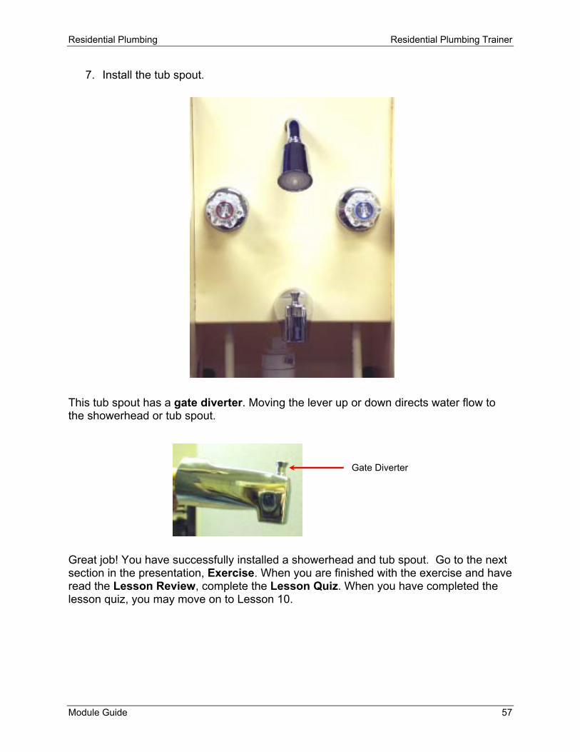
Module Guide 57
7. Install the tub spout. This tub spout has a gate diverter. Moving the lever up or down directs water flow to the showerhead or tub spout. Great job! You have successfully installed a showerhead and tub spout. Go to the next section in the presentation, Exercise. When you are finished with the exercise and have read the Lesson Review, complete the Lesson Quiz. When you have completed the lesson quiz, you may move on to Lesson 10.
Gate Diverter

Residential Plumbing Residential Plumbing Trainer
58 Module Guide
Lesson 10 – Install a Hose Bib When you have completed this lesson, you will be able to: • mount a hose bib on the trainer. • connect a hose bib to the water supply. MATERIAL LIST 1 – Hose bib w/mounting screws 1 – ½-inch CPVC male adapter 1 – ½-inch CPVC elbow 1 – ½-inch CPVC T-fitting 2ft (61cm) x ½-inch CPVC pipe TOOLS YOU'LL NEED Adjustable wrench Hacksaw Felt-tipped pen Tape measure Allen wrench Safety goggles Bench vise Use the bench vise and wear safety goggles whenever you are cutting pipe. You may view a video of this activity by going to Lesson 10 on your computer. Click on the icon for the video titled “Install a Hose Bib.” This video can be paused or repeated as often as necessary to complete this lesson.
Residential Plumbing Residential Plumbing Trainer
Module Guide 59
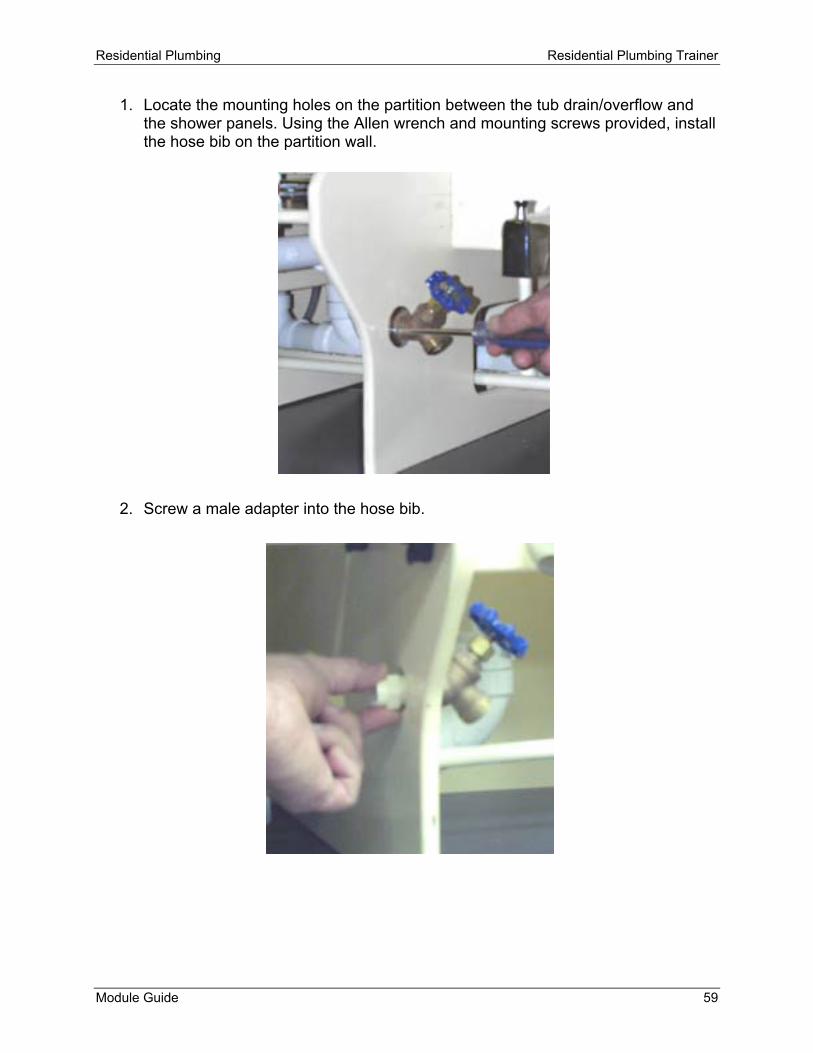
1. Locate the mounting holes on the partition between the tub drain/overflow and the shower panels. Using the Allen wrench and mounting screws provided, install the hose bib on the partition wall.
2. Screw a male adapter into the hose bib.

Residential Plumbing Residential Plumbing Trainer
60 Module Guide
3. Measure the cold water pipe 3-inches (7.5cm) back from the partition, and then mark the pipe.
4. Temporarily remove the cold water pipe that was roughed in earlier and cut it at the mark.
5. Reinstall the pipe by reconnecting it to the T-fitting below the kitchen faucet.
6. Attach a T-fitting to the end of this pipe.

Residential Plumbing Residential Plumbing Trainer
Module Guide 61
7. Measure and cut the remaining pipe so that it connects to the T-fitting and can be reconnected to the shower faucet.
8. Measure and cut a 2-inch (5cm) piece of pipe and fit it into the hose bib, then
place an elbow on the end of the pipe.
9. Measure and cut a short piece of pipe to make the final connection between the hose bib and the water supply.

Residential Plumbing Residential Plumbing Trainer
62 Module Guide
Hose bibs are compression faucets with male threads on the spout for hooking up to a garden hose. A frost-proof sillcock is a hose bib with a built-in anti-siphon device. The stem on a sillcock can run from 6-inches to 30-inches (15-76 cm) inside the house. As you shut off a sillcock, water throughout the length of the extension tube drains out. Therefore it is important to install a sillcock with a slight downward slant. Congratulations, you have successfully installed a hose bib. Go to the next section in the presentation.

Residential Plumbing Residential Plumbing Trainer
Module Guide 63
Independent Study Projects Choose one of the Independent Study Projects from the list below. When you have completed your project, give it to your instructor for review. 1. Use the Internet or your local library to research the basics of plumbing. Pay specific
attention to information on how to properly use copper pipes in plumbing. Describe the methods and step-by-step processes used for cutting and soldering copper pipe.
2. Describe why plumbing permits and inspections are necessary. 3. Describe the siphoning action of a toilet. Write the steps that take place when a toilet
is flushed.
Residential Plumbing Residential Plumbing Trainer
64 Module Guide

Reference A – Tools and Fittings
Module Guide 65
REFERENCE A – TOOLS AND FITTINGS
1½" PVC Pipe ½" CPVC Pipe
1½" Waste T-Fitting 1½" Trap w/Coupling
1½" PVC Elbow 1½" Trap Adapter
½" CPVC T-Fitting
½" CPVC Male Adapter
Teflon Tape Drop Elbow
½" CPVC Elbow
Cleanout
Faucet Grease
Double Drain
Waste Cross 1½" Tailpiece Flexible Supply Tube

Residential Plumbing Residential Plumbing Trainer
66 Module Guide
Channel-Type Pliers
Hacksaw
Adjustable Wrench
Sanding Cloth
Vise
Phillips and Slotted Screwdrivers
Tape Measure
Basin Wrench Street Elbow
Shutoff Valve

Reference B – How to Measure Plastic Pipe
Module Guide 67
REFERENCE B – HOW TO MEASURE PLASTIC PIPE
When you measure pipe, include the distance between the bottoms of the fitting sockets. Remember that adding the extra length of the fittings will determine the run of the pipe. This will vary, according to the size and type of fittings being used.

Residential Plumbing Residential Plumbing Trainer
68 Module Guide

Reference C – Blow-Up Diagrams
Module Guide 69
REFERENCE C – BLOW-UP DIAGRAMS Tub Drain/Overflow Assembly Generic – No Trip Lever
Residential Plumbing Residential Plumbing Trainer
70 Module Guide
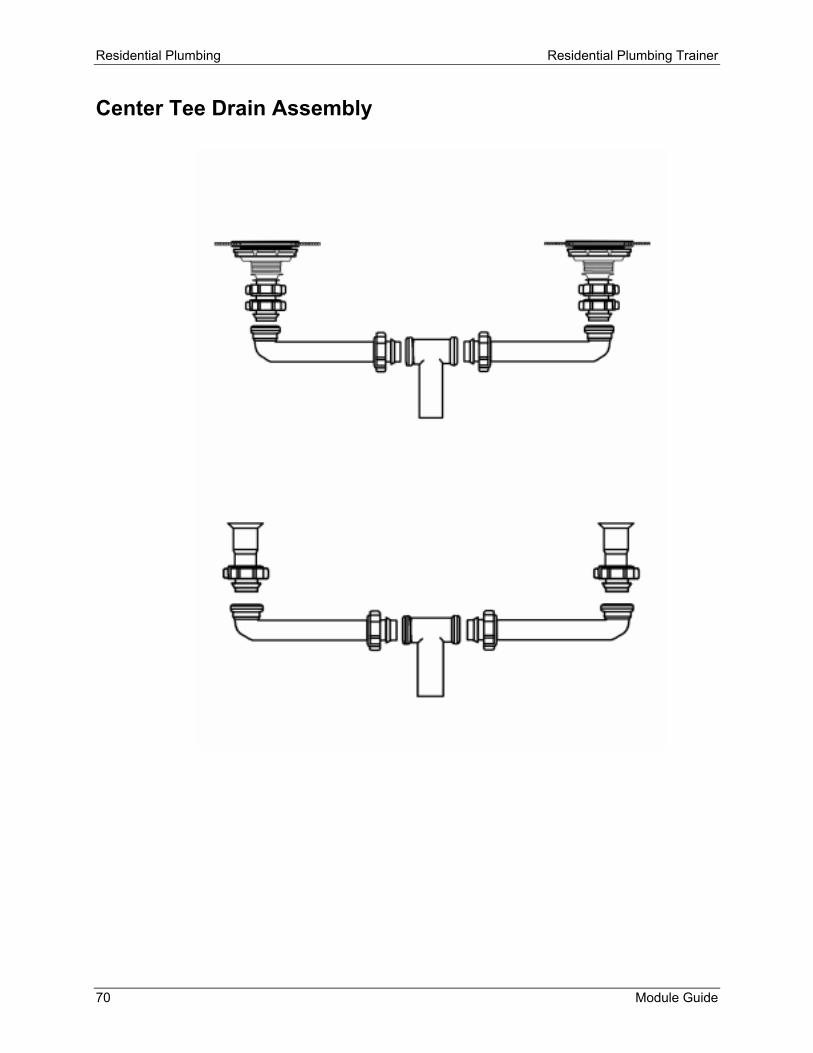
Center Tee Drain Assembly

Reference C – Blow-Up Diagrams
Module Guide 71
Basket Strainer Assembly

Residential Plumbing Residential Plumbing Trainer
72 Module Guide
THIS

THIS