3.3 one wire communication touch memories i - buttons references 1. 2
TRANSCRIPT
3.3 ONE WIRE COMMUNICATION
TOUCH MEMORIESI - BUTTONS
References1. http://www.ibutton.com/2. http://www.atstake.com/research/reports/practical_introduction_to_ibutton.pdf3. http://www.mrioftx.com/ibuttons/overview.html4. http://berk.tc/intercon/standard.pdf5. https://store.ibutton.com/cgi-bin/ncommerce3/CategoryDisplay?cgrfnbr=808&cgmenbr=776&cg=808
Interconncection ProtocolsBy Berk USTUNDAGIstanbul Technical University
What is an iButton ?
The iButton® is a 16mm computer chip armored in a stainless steel can.Upto-date information can travel with a person or object.Product of Dallas Semiconductors Inc.
Properties Rugged enough – withstand harsh outdoor environmentsDurability – enough for a person to wear everyday on a digitial accessory
( ring, watch, wallet etc )

iButton Types
Memory iButton Java™-powered cryptographic iButton Thermochron iButton
Each has a guaranteed-unique registration number engraved in silicon.
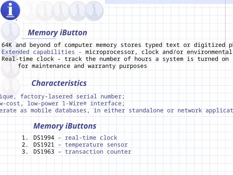
Memory iButton 64K and beyond of computer memory stores typed text or digitized photos Extended capabilities - microprocessor, clock and/or environmental sensors . Real-time clock - track the number of hours a system is turned on for maintenance and warranty purposes
Characteristics
Unique, factory-lasered serial number; Low-cost, low-power 1-Wire® interface; Operate as mobile databases, in either standalone or network application designs
Memory iButtons
1. DS1994 – real-time clock2. DS1921 – temperature sensor 3. DS1963 – transaction counter
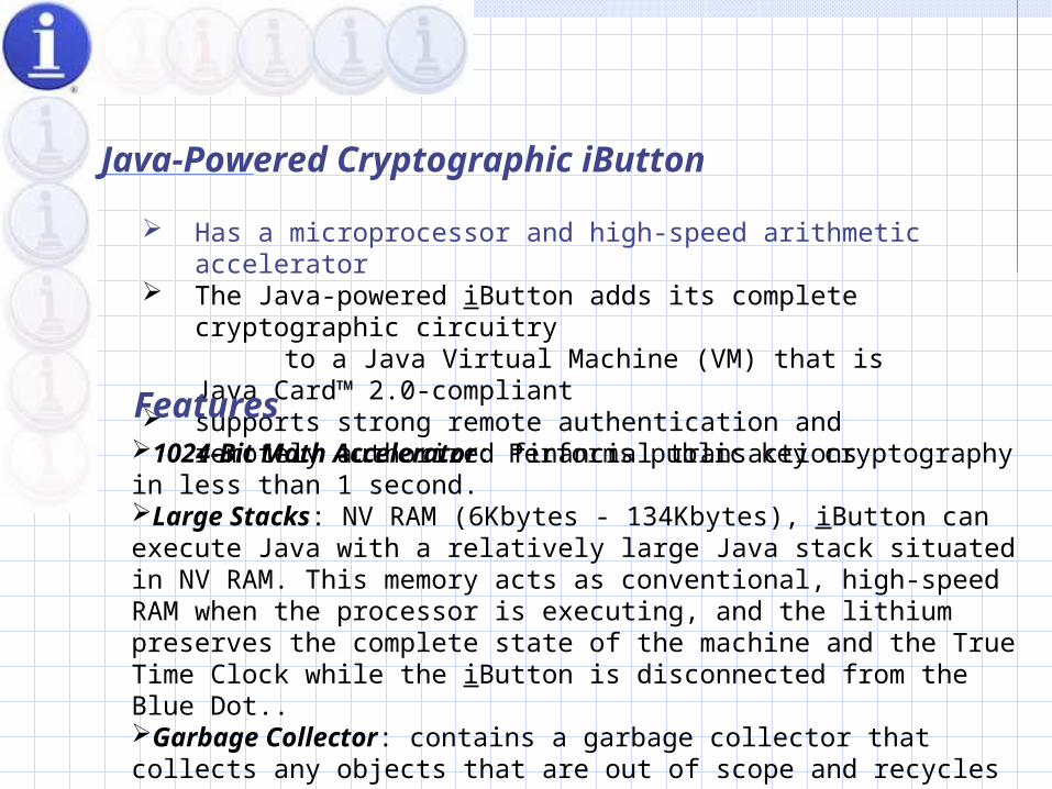
Java-Powered Cryptographic iButton
Has a microprocessor and high-speed arithmetic accelerator The Java-powered iButton adds its complete cryptographic circuitry to a Java Virtual Machine (VM) that is Java Card™ 2.0-compliant supports strong remote authentication and remotely authorized
financial transactions
Features1024-Bit Math Accelerator: Performs public key cryptography in less than 1 second. Large Stacks: NV RAM (6Kbytes - 134Kbytes), iButton can execute Java with a relatively large Java stack situated in NV RAM. This memory acts as conventional, high-speed RAM when the processor is executing, and the lithium preserves the complete state of the machine and the True Time Clock while the iButton is disconnected from the Blue Dot.. Garbage Collector: contains a garbage collector that collects any objects that are out of scope and recycles the memory for future use.
Thermochron iButton
Tracks time and temperature – key to freshness of many products integrates a thermometer, a clock/calendar, a thermal history log, and 512
bytes of additional memory to store a shipping manifest.
characteristics
Easily attachable measures temperature from -40°C to +85°C in 0.5° increments logs data for more than 10 years or up to 1 million temperature measurements. Stores temperature in two formats - time-temperature & Histogram
Missioningthe PC or handheld's Blue Dot receptor Viewing and Tracking Thermochron Data on the Web
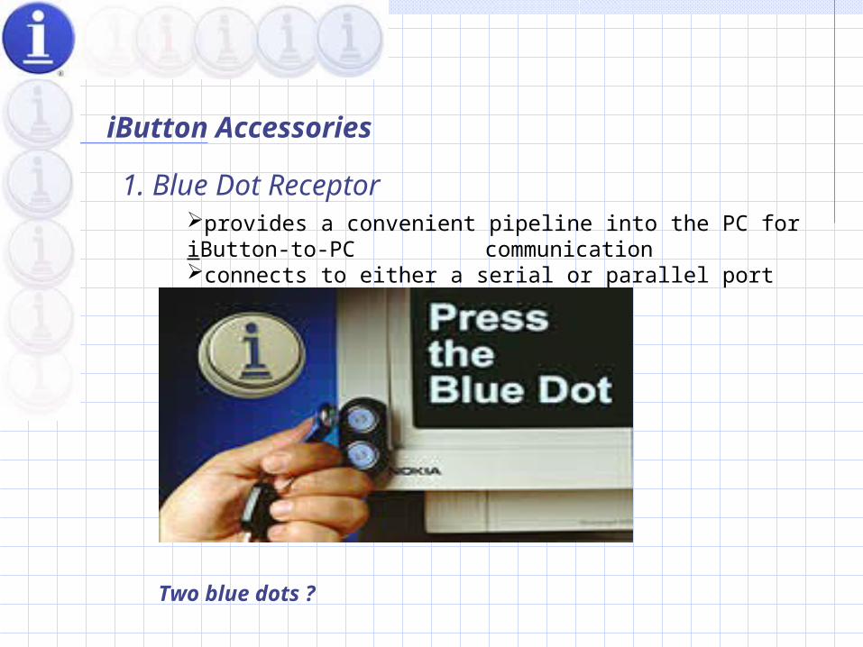
iButton Accessories
1. Blue Dot Receptorprovides a convenient pipeline into the PC for iButton-to-PC communication connects to either a serial or parallel port
Two blue dots ?
Digital Jewelries
ring, key chain, wallet, watch, or metal card Reasons ?
- Locked door access - Computer log-on - Coin purse - Medical information - Internet transactions - Citizen credential (driver's license, passport, etc.)
Pictures.

Applications
•Reliable, Cashless Transactions •Increasing Efficiency and Quality Control •Access Control •Asset Tracking •Electronic Identity and Medical Data •Electronic Identity and Time & Attendance •Internet Commerce
Technical Overview
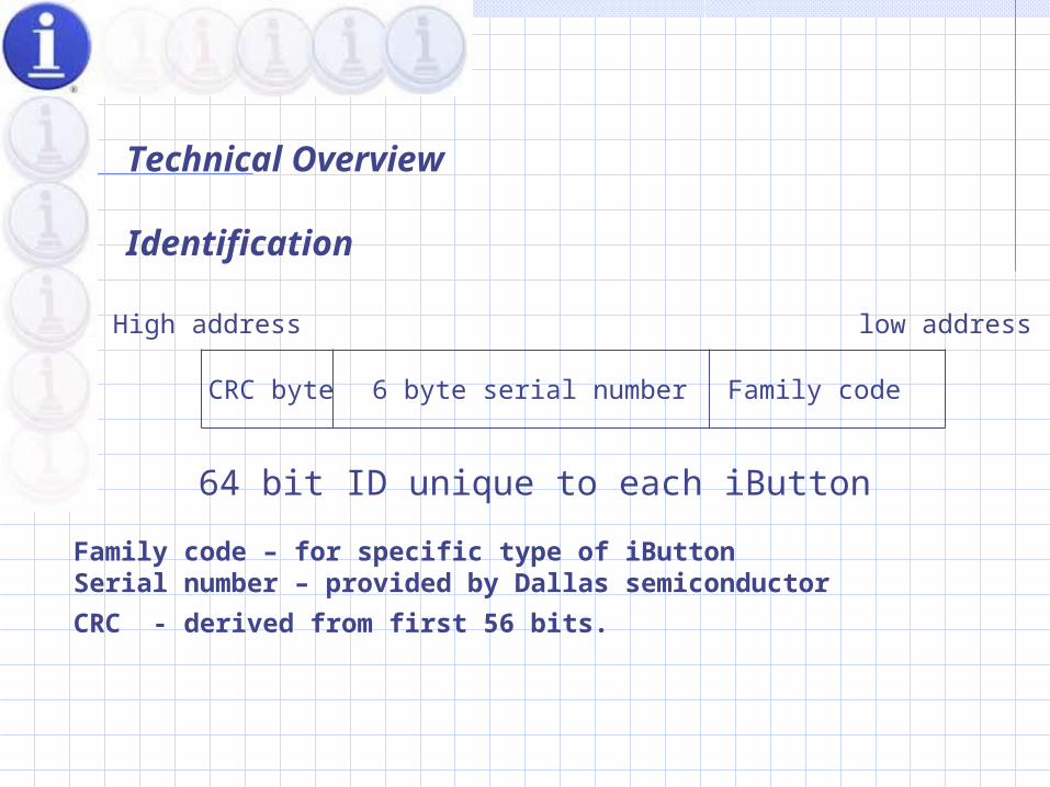
Identification
CRC byte 6 byte serial number Family code
High address low address
64 bit ID unique to each iButton
Family code – for specific type of iButtonSerial number – provided by Dallas semiconductor
CRC - derived from first 56 bits.
Communication
Touch Reset- check for the presense of an iButton and send a required Reset pulse to prepare it for data communication
Touch Byte- core data transfer routine, specific iButton commands are sent using this routine and the response from the iButtondevice is returned.
Some commands, READ ROM, SKIP ROM, MATCH ROM, SEARCH ROMREAD MEMORY, READ/WRITE SUBKEY, READ/WRITE SCRATCH PAD, COPY SCRATCHPAD
Zeroization
The monolithic chip includes up to 134K of SRAM that is specially designed so that it will rapidly erase its contents as a tamper response to an intrusion.
Specific intrusions that result in zeroization include:
- Opening the case - Removing the chip's metallurgically bonded substrate barricade - Micro-probing the chip - Subjecting the chip to temperature extremes
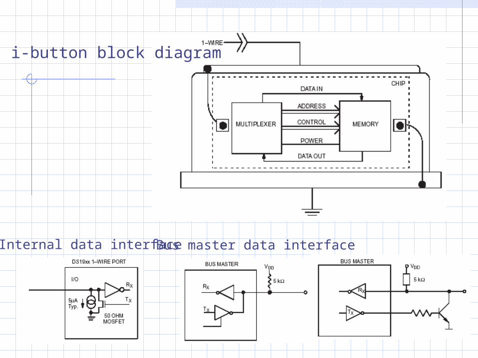
i-button block diagram
Internal data interface Bus master data interface
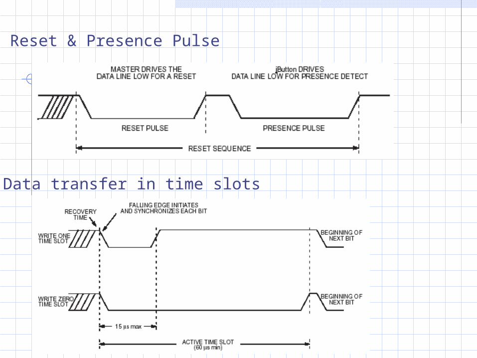
Reset & Presence Pulse
Data transfer in time slots
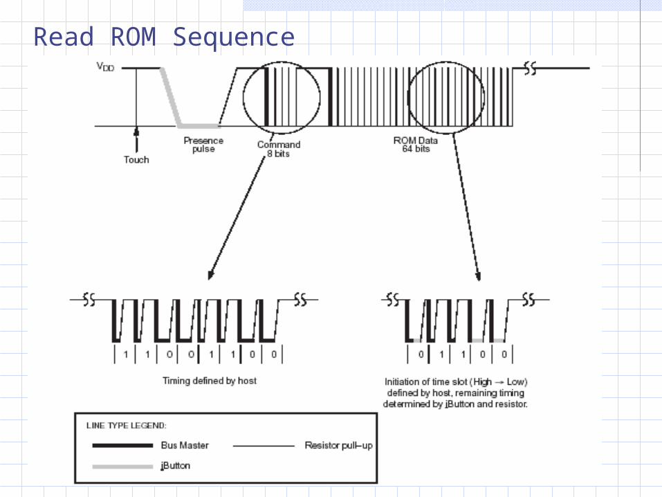
Read ROM Sequence
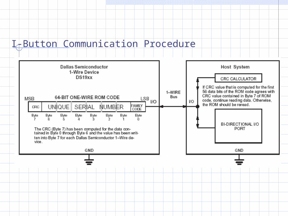
I-Button Communication Procedure
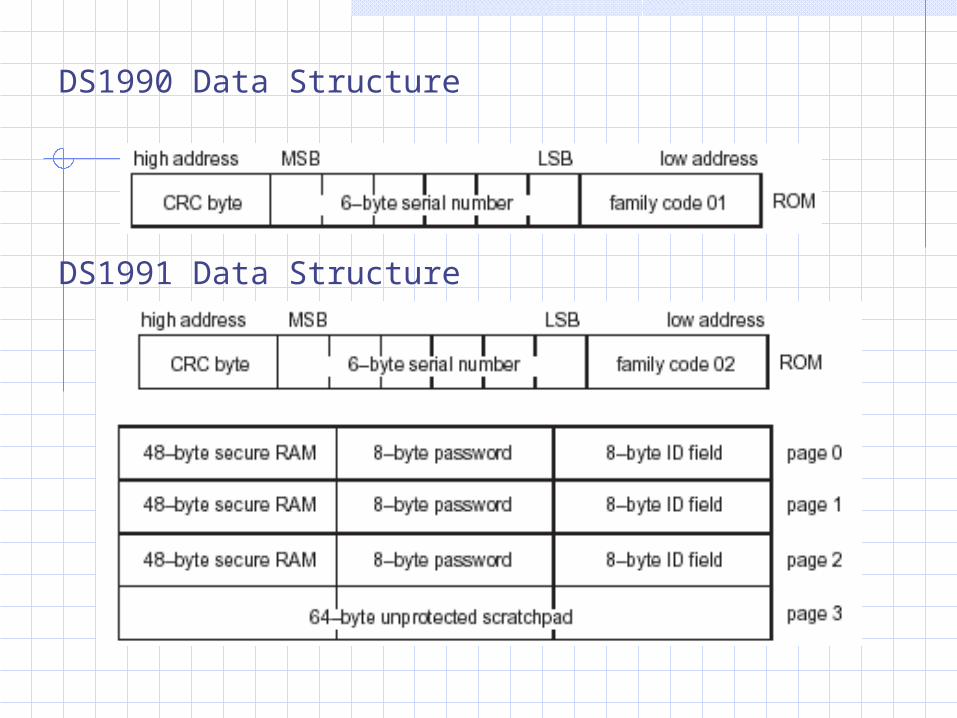
DS1990 Data Structure
DS1991 Data Structure
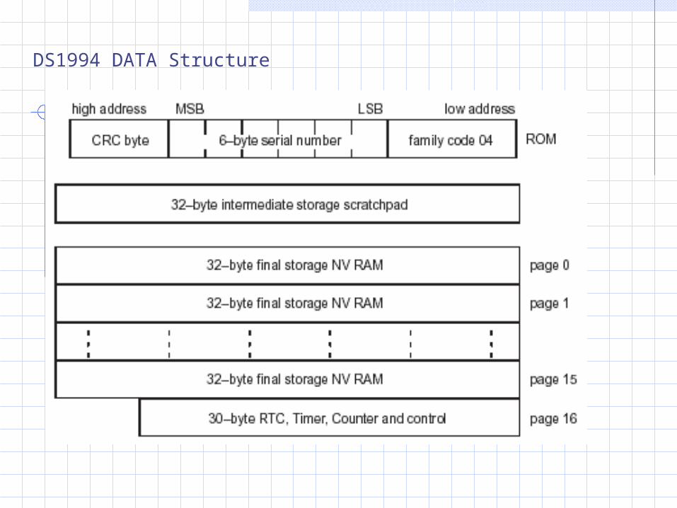
DS1994 DATA Structure

Mechanical Standards
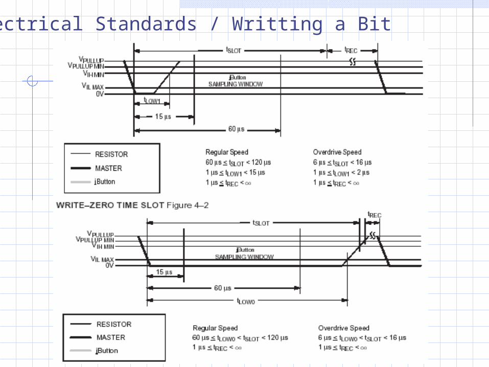
Electrical Standards / Writting a Bit
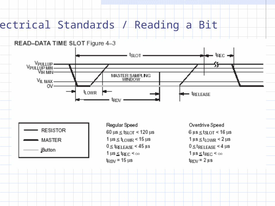
Electrical Standards / Reading a Bit
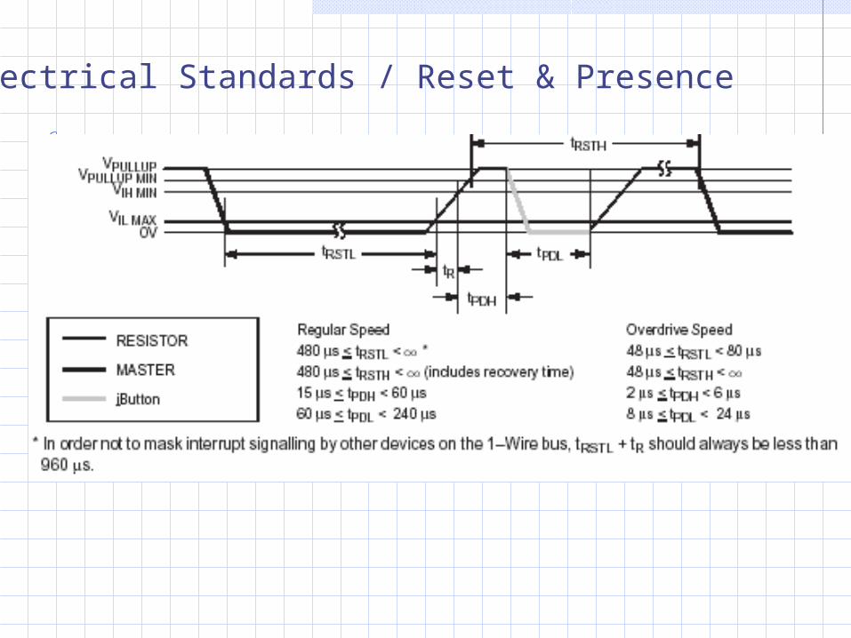
Electrical Standards / Reset & Presence

Rom Functions Flow Chart
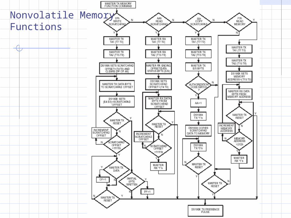
Nonvolatile MemoryFunctions
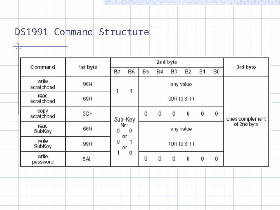
DS1991 Command Structure
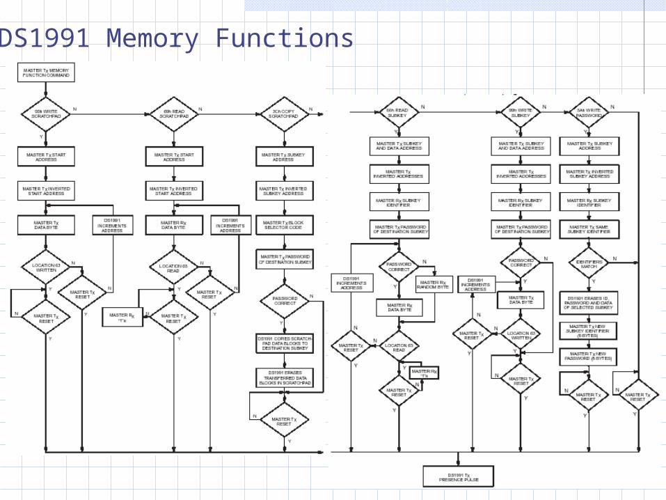
DS1991 Memory Functions
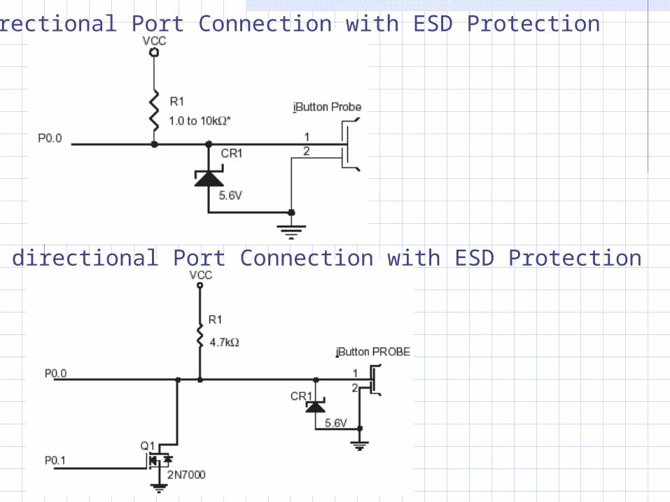
Bidirectional Port Connection with ESD Protection
Fixed directional Port Connection with ESD Protection
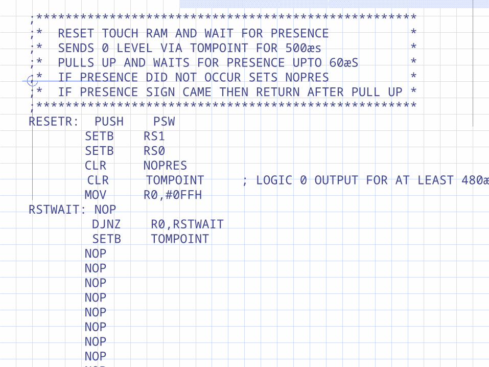
;****************************************************;* RESET TOUCH RAM AND WAIT FOR PRESENCE *;* SENDS 0 LEVEL VIA TOMPOINT FOR 500æs *;* PULLS UP AND WAITS FOR PRESENCE UPTO 60æS *;* IF PRESENCE DID NOT OCCUR SETS NOPRES * ;* IF PRESENCE SIGN CAME THEN RETURN AFTER PULL UP *;****************************************************RESETR: PUSH PSW
SETB RS1 SETB RS0 CLR NOPRES
CLR TOMPOINT ; LOGIC 0 OUTPUT FOR AT LEAST 480æs MOV R0,#0FFH
RSTWAIT: NOP DJNZ R0,RSTWAIT SETB TOMPOINT NOP NOP NOP NOP NOP NOP NOP NOP NOP NOP
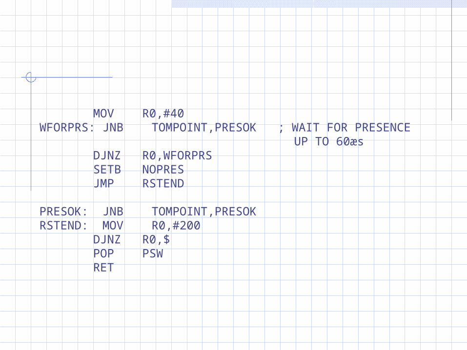
MOV R0,#40WFORPRS: JNB TOMPOINT,PRESOK ; WAIT FOR PRESENCE
UP TO 60æs DJNZ R0,WFORPRS SETB NOPRES JMP RSTEND
PRESOK: JNB TOMPOINT,PRESOKRSTEND: MOV R0,#200
DJNZ R0,$ POP PSW RET
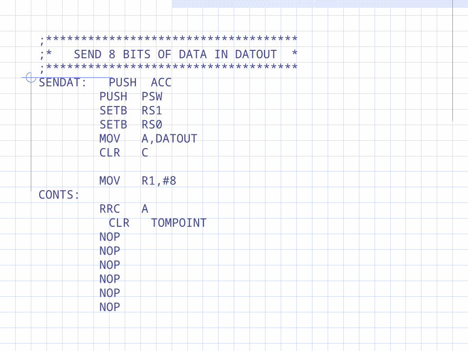
;************************************;* SEND 8 BITS OF DATA IN DATOUT *;************************************SENDAT: PUSH ACC
PUSH PSW SETB RS1 SETB RS0 MOV A,DATOUT CLR C MOV R1,#8
CONTS: RRC A
CLR TOMPOINT NOP NOP NOP NOP NOP NOP

MOV TOMPOINT,C MOV R0,#30 ; WAIT TILL END OF TIME SLOT DJNZ R0,$
SETB TOMPOINT MOV R0,#30 DJNZ R0,$
NOP ; WAIT 5æs FOR trec NOP NOP NOP NOP NOP NOP
DJNZ R1,CONTS ; IF DATA HAS NOT REACHED 8 BITS THEN CONTINUE BY SENDING NEXT BIT
POP PSW POP ACC RET

;************************************;* READ 8 BITS OF DATA INTO DATIN *;************************************READAT: PUSH PSW
PUSH ACC SETB RS1 SETB RS0 MOV DATIN,#0 MOV A,#00000001B
NEXTBIT: CLR TOMPOINT MOV R0,#5 ; PREVIOUSLY 5
DJNZ R0,$ SETB TOMPOINT
MOV R0,#5 DJNZ R0,$
JNB TOMPOINT,ZEROBIT0 ORL DATIN,A
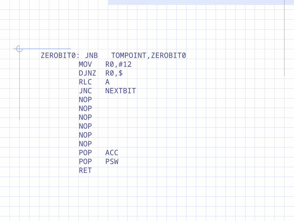
ZEROBIT0: JNB TOMPOINT,ZEROBIT0 MOV R0,#12 DJNZ R0,$ RLC A JNC NEXTBIT NOP NOP NOP NOP NOP NOP POP ACC POP PSW RET
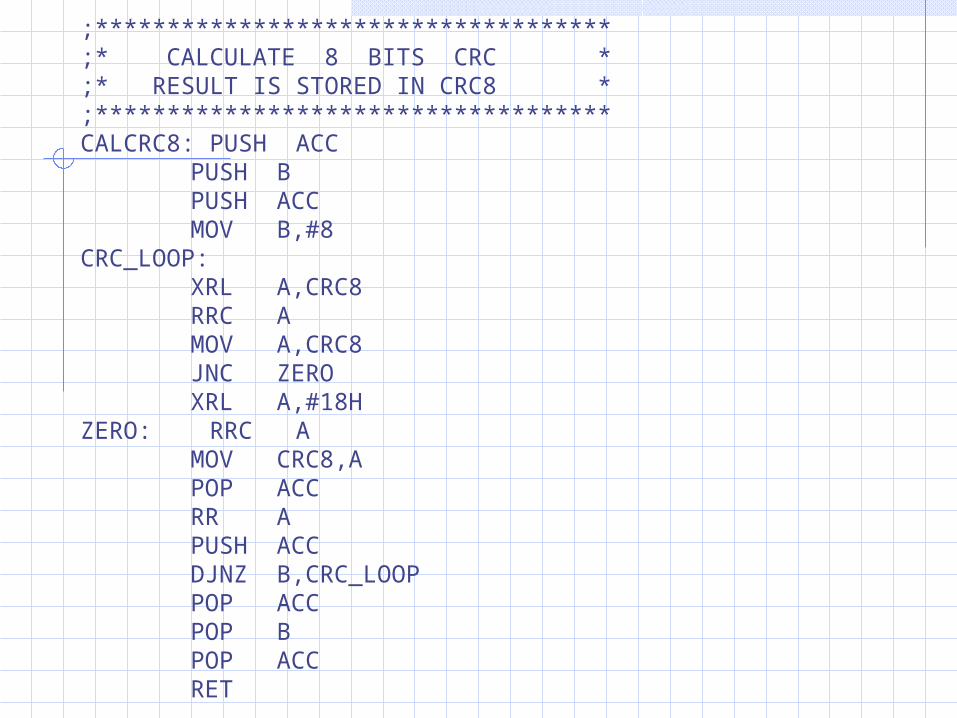
;************************************;* CALCULATE 8 BITS CRC *;* RESULT IS STORED IN CRC8 *;************************************CALCRC8: PUSH ACC
PUSH B PUSH ACC MOV B,#8
CRC_LOOP: XRL A,CRC8 RRC A MOV A,CRC8 JNC ZERO XRL A,#18H
ZERO: RRC A MOV CRC8,A POP ACC RR A PUSH ACC DJNZ B,CRC_LOOP POP ACC POP B POP ACC RET
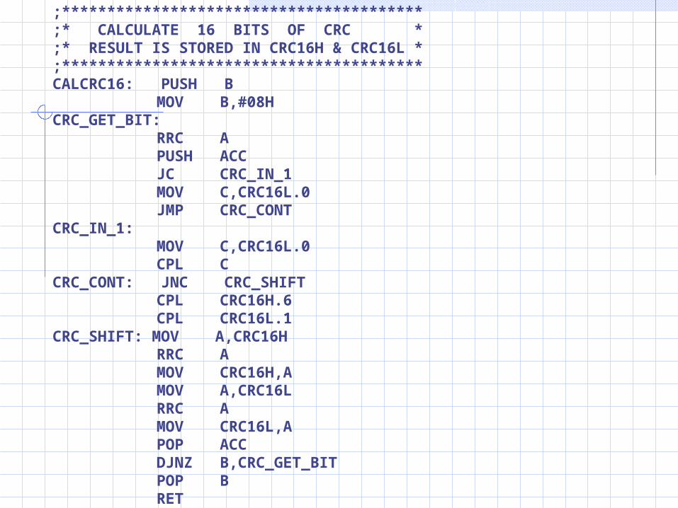
;****************************************;* CALCULATE 16 BITS OF CRC *;* RESULT IS STORED IN CRC16H & CRC16L *;****************************************CALCRC16: PUSH B
MOV B,#08HCRC_GET_BIT:
RRC A PUSH ACC JC CRC_IN_1 MOV C,CRC16L.0 JMP CRC_CONT
CRC_IN_1: MOV C,CRC16L.0 CPL C
CRC_CONT: JNC CRC_SHIFT CPL CRC16H.6 CPL CRC16L.1
CRC_SHIFT: MOV A,CRC16H RRC A MOV CRC16H,A MOV A,CRC16L RRC A MOV CRC16L,A POP ACC DJNZ B,CRC_GET_BIT POP B RET

READROM: MOV DATOUT,#33H ; COMMAND=READ ROM CALL SENDAT MOV R0,#8
MOV R1,#38H ;DATA BUFFER STARTS AT 38HROMDAT1: CALL READAT ;READ ROM INTO 38H..40H
MOV @R1,DATIN INC R1 DJNZ R0,ROMDAT1
MOV R1,#38HRETCRC1: MOV A,@R1 ; CALCULATE AND COMPARE CRC
CALL CALCRC8 INC R1
CJNE R1,#40H,RETCRC1 MOV A,CRC8
JZ READYSUB ; IF CRC IS OK THEN PASS TO MEMORY OPERATIONS
DJNZ R7,RESRAM SETB BADCRC
JMP READREND ; IF CRC IS BAD THEN END
“Read ROM” command
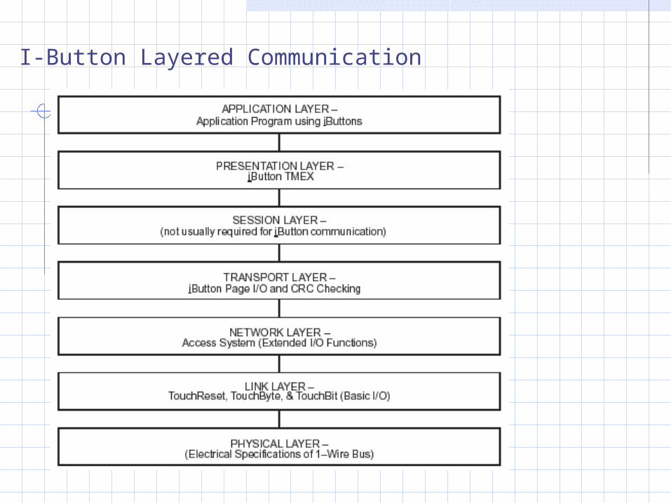
I-Button Layered Communication
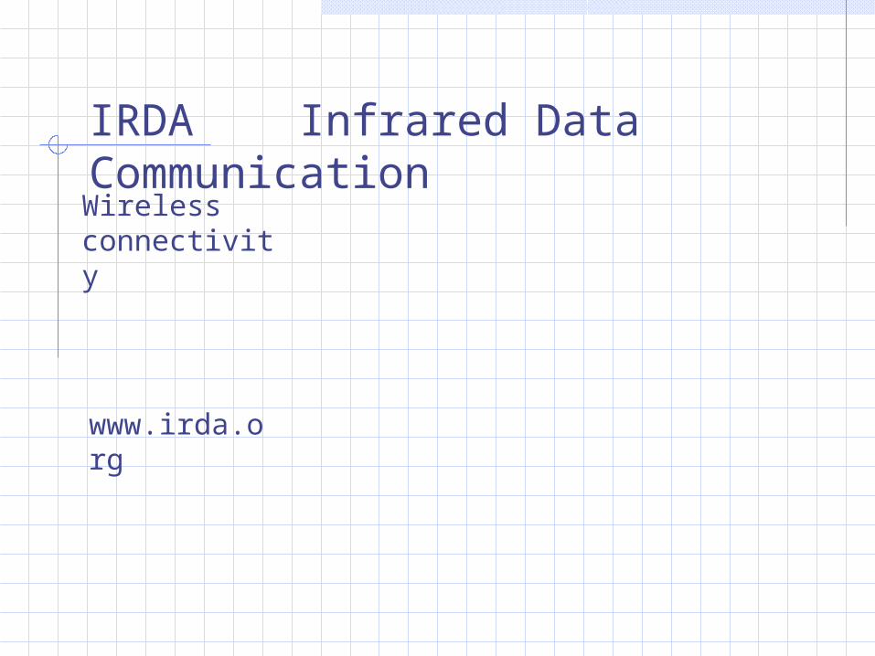
IRDA Infrared Data CommunicationWireless connectivity
www.irda.org
The Infrared Data Association or IrDA was formed to create standards for interoperability between devices using simple low cost infrared data links. Most PCs built today offer support for the IrDA standards. And a wide variety of peripherals using IrDA are available today, including keyboards, game controllers, joysticks, printers, and digital cameras.
The original IrDA specification provided for a maximum data rate of 115.2 kbps, but IrDA has been extended to greater speeds. Currently,
IrDA 1.1 supports speeds up to 4 Mbps and work is under way to increase speeds to 16 and possibly 32 Mbps. IrDA does not limit itself to just the physical specification either.
IrDA takes a layered protocol approach specifying several layers of protocols including 1- IrPHY (physical layer), 2- IrLAP (link access protocol) and 3- IrLMP (link managment protocol).
The specification also groups devices into two classes: IrDA Data and IrDA Control. IrDA Data covers data that may need to transport large amounts of data devices such as printers and digital cameras. And IrDA Control covers control devices including mice, keyboards, game controllers, and so on.
Beyond the required protocol layers.( IrPHY, IrLAP, and IrLMP), there are numerous optional protocols that help with various kinds of applications. For example, the IrTran-p protocol is commonly used in digital cameras for transferring pictures back to a host computer.
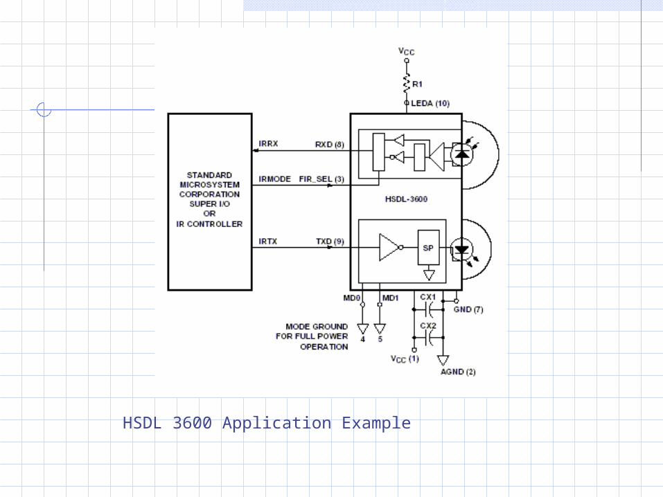
HSDL 3600 Application Example