33 and 35 exit devices - coralind.us duprin 33 series...hardware, and are tested in ... 33 and 35...
TRANSCRIPT

33 and 35 Exit Devices T
2
INDEX
Introduction . . . . . . . . . . . . . . . . . . . . . . . . . . . . . . . . . . . . . . . . . . . . . . . . . . . . . . . . . . . . . . . . . . . . . . . . . . . . . . . 3
Exit Hardware Rim device. . . . . . . . . . . . . . . . . . . . . . . . . . . . . . . . . . . . . . . . . . . . . . . . . . . . . . . . . . . . . . . . . . . . . . . . . . . . . . . . 4Surface mounted vertical rod device . . . . . . . . . . . . . . . . . . . . . . . . . . . . . . . . . . . . . . . . . . . . . . . . . . . . 5Concealed vertical rod device . . . . . . . . . . . . . . . . . . . . . . . . . . . . . . . . . . . . . . . . . . . . . . . . . . . . . . . . . 6-7
Fire Exit Hardware Concealed vertical rod device . . . . . . . . . . . . . . . . . . . . . . . . . . . . . . . . . . . . . . . . . . . . . . . . . . . . . . . . 8 -9
Trim Selection . . . . . . . . . . . . . . . . . . . . . . . . . . . . . . . . . . . . . . . . . . . . . . . . . . . . . . . . . . . . . . . . . . . . . . . . . . . . . . . . . . . . . . . 10-11
Device Options ALK Alarm kit . . . . . . . . . . . . . . . . . . . . . . . . . . . . . . . . . . . . . . . . . . . . . . . . . . . . . . . . . . . . . . . . . . . . . . . . . . . 13Cylinder dogging . . . . . . . . . . . . . . . . . . . . . . . . . . . . . . . . . . . . . . . . . . . . . . . . . . . . . . . . . . . . . . . . . . . . . . . . 16Electric latch retraction . . . . . . . . . . . . . . . . . . . . . . . . . . . . . . . . . . . . . . . . . . . . . . . . . . . . . . . . . . . . . . . . . 14LX Latch bolt monitoring . . . . . . . . . . . . . . . . . . . . . . . . . . . . . . . . . . . . . . . . . . . . . . . . . . . . . . . . . . . . . . . 15RX Request to exit switch . . . . . . . . . . . . . . . . . . . . . . . . . . . . . . . . . . . . . . . . . . . . . . . . . . . . . . . . . . . . . . 14SS Signal switch . . . . . . . . . . . . . . . . . . . . . . . . . . . . . . . . . . . . . . . . . . . . . . . . . . . . . . . . . . . . . . . . . . . . . . . . 15
Accessories CDK Cylinder dogging kit. . . . . . . . . . . . . . . . . . . . . . . . . . . . . . . . . . . . . . . . . . . . . . . . . . . . . . . . . . . . . . . 16HDK Hex key dogging kit . . . . . . . . . . . . . . . . . . . . . . . . . . . . . . . . . . . . . . . . . . . . . . . . . . . . . . . . . . . . . . . 16Electric power transfer . . . . . . . . . . . . . . . . . . . . . . . . . . . . . . . . . . . . . . . . . . . . . . . . . . . . . . . . . . . . . . . . . . 16Power supplies . . . . . . . . . . . . . . . . . . . . . . . . . . . . . . . . . . . . . . . . . . . . . . . . . . . . . . . . . . . . . . . . . . . . . . . . . . 17Dummy push bar. . . . . . . . . . . . . . . . . . . . . . . . . . . . . . . . . . . . . . . . . . . . . . . . . . . . . . . . . . . . . . . . . . . . . . . . 17Cylinders . . . . . . . . . . . . . . . . . . . . . . . . . . . . . . . . . . . . . . . . . . . . . . . . . . . . . . . . . . . . . . . . . . . . . . . . . . . . . . . . 18Optional levers . . . . . . . . . . . . . . . . . . . . . . . . . . . . . . . . . . . . . . . . . . . . . . . . . . . . . . . . . . . . . . . . . . . . . . . . . . 11SS-333 Signal switch trim . . . . . . . . . . . . . . . . . . . . . . . . . . . . . . . . . . . . . . . . . . . . . . . . . . . . . . . . . . . . . . 16Vertical rod and latch guard . . . . . . . . . . . . . . . . . . . . . . . . . . . . . . . . . . . . . . . . . . . . . . . . . . . . . . . . . . . . 13
Additional Information ANSI grade, type & function. . . . . . . . . . . . . . . . . . . . . . . . . . . . . . . . . . . . . . . . . . . . . . . . . . . . . . . . . . . . 18Device dimensions. . . . . . . . . . . . . . . . . . . . . . . . . . . . . . . . . . . . . . . . . . . . . . . . . . . . . . . . . . . . . . . . . . . . . . 19Finishes . . . . . . . . . . . . . . . . . . . . . . . . . . . . . . . . . . . . . . . . . . . . . . . . . . . . . . . . . . . . . . . . . . . . . . . . . . . . . . . . . 19Fire label ratings/applications . . . . . . . . . . . . . . . . . . . . . . . . . . . . . . . . . . . . . . . . . . . . . . . . . . . . . . . . . . 18Handing . . . . . . . . . . . . . . . . . . . . . . . . . . . . . . . . . . . . . . . . . . . . . . . . . . . . . . . . . . . . . . . . . . . . . . . . . . . . . . . . . 18How-To-Order Information. . . . . . . . . . . . . . . . . . . . . . . . . . . . . . . . . . . . . . . . . . . . . . . . . . . . . . . . . . . . . . 21Nomenclature . . . . . . . . . . . . . . . . . . . . . . . . . . . . . . . . . . . . . . . . . . . . . . . . . . . . . . . . . . . . . . . . . . . . . . . . . . . 22Popular double door applications . . . . . . . . . . . . . . . . . . . . . . . . . . . . . . . . . . . . . . . . . . . . . . . . . . . . . . 20Strike application/minimum stile . . . . . . . . . . . . . . . . . . . . . . . . . . . . . . . . . . . . . . . . . . . . . . . . . . . . . . . 12
Q 1997 Ingersoll-Rand Co. May be copied for use with specification submittal.

T

INTRODUCTION
The proper selection and application of exit hardware, in addition to safety, are majorconcerns to all responsible manufacturers. Exit devices are a critical part of a dooropening or access system and will provide safe and reliable service when properlyapplied and maintained. It is the policy of Von Duprin Division, Ingersoll-RandCompany, to design and manufacture exit devices to a high standard of quality andreliability in accordance with accepted U.S. domestic and international standards. All33 and 35 series exit devices are UL listed for Accident Hazard and Fire ExitHardware, and are tested in accordance to ANSI A156.3, 1994, Grade I.
It is intended that the information included in this publication, when properly used, willprovide clear and reliable guidelines to the proper general selection and application.However, the scope of the information is necessarily limited.
Unusual operating conditions and environments and other external influences canaffect the proper application of the products represented. Modifications of theseproducts will also affect UL listings. It is recommended that whenever an unusualapplication condition exists, or when any modification of a product is considered,that our engineers review the application.
Application engineering services are available to help ensure proper selection or toreview any areas where users of Von Duprin products may have questions.
33 Series f eatures gr ooved mec hanism case .
35 Series f eatures smooth mec hanism case .
Von Duprin push pad exit devices are available in two external surface styles,designated 33 series and 35 series.
The two styles are mechanically and dimensionally identical and provide a wideselection of appearance options.
THE QUIET ONE®
A fluid dampener decelerates the push pad on its return stroke and eliminates mostnoise associated with exit device operations. Furnished on all 33/35 series exitdevices.
33 and 35 Exit De vices T
3

33 and 35 Rim Devices T
4
33 and 35 rim devices for all types of single and double doors with mullion, ULlisted for accident hazard installations. Fits door stiles as narrow as 1¾9 (44mm).
FEATURES
● Nonhanded ● Seven popular finishes● Field sizeable ● Hex key dogging● 3/49 (19mm) throw latch bolt
DIMENSIONS
Touchbar height to finished floor 3913/169 (1011mm) at center
Touchbar projection —neutral 313/169 (97mm)depressed 31/169 (78mm)
Center case 7½9225/169215/169 (191mm259mm233mm)
Device length — Short 38 (914mm) 2869 to 38 (762mm to 914mm) door sizeDevice length — Long 48 (1219mm) 3819 to 48 (940mm to 1219mm) door size
STRIKE AND FASTENERS
Device is furnished standard with 1409 strike in dull black finish. For strikedimensions and optional strike information, refer to page 12. Sex nuts and bolts arefurnished standard for mounting on 13/49 (44mm) and 21/49 (57mm) thick doors.
DEVICE OPTIONS
Electric latch retraction, page 14.Request to exit switch, page 14.Latch bolt monitoring switch, page 15.Signal switch, page 15.Cylinder dogging, page 16.
For How-To-Order information on all devices, see page 21.
OUTSIDE TRIMStandard
333NL-TP334333DT370L
Optional
3308NL3308DT370T3342550DT
For complete outside triminformation, see pages10-11.
1409

33 and 35 Surface Mounted Vertical Rod De vice T
5
3327 and 3527 surface mounted ver tical r od de vices for all types of single ordouble doors, UL listed for accident hazard installations. Fits door stiles as narrow as13/49 (44mm).
Vertical rod and latch guards are available to protect the bottom rod of the exitdevice from the damaging impacts of carts or gurneys passing through doors. Referto page 13.
FEATURES
● Nonhanded ● Seven popular finishes● Field sizeable ● Hex key dogging● 5/89 (16mm) throw latch bolt
DIMENSIONS
Touchbar height to finished floor 3913/169 (1011mm) at center
Touchbar projection —neutral 313/169 (97mm)depressed 31/169 (78mm)
Center case 71/29225/169215/169 (191mm259mm233mm)
Device length — Short 38 (914mm) 2869 to 38 (762mm to 914mm) door sizeDevice length — Long 48 3819 to 48 (940mm to 1219mm) door size
Top & bottom latch case 49217/89211/29 (1219mm248mm238mm)
Vertical rods 1/29 (13mm) square tubing
STRIKES AND FASTENERS
Device is furnished standard 248L-4, 266, and 304L strikes. For strike dimensionsand optional strike information, refer to page 12. Sex nuts and bolts are furnishedstandard for mounting on 13/49 (44mm) and 21/49 (57mm) thick doors.
DEVICE OPTIONS
Electric latch retraction, page 14.Request to exit switch, page 14.Latch bolt monitoring switch, page 15.Signal switch, page 15.Cylinder dogging, page 16.
For Ho w-To-Order inf ormation on all de vices, see page 21.
OUTSIDE TRIMStandar d
333NL-TP333DT370L374T2333DT
For complete outside triminformation, see pages10-11.
266 248L-4 304L265
33 and 35 Concealed Vertical Rod De vice T
6
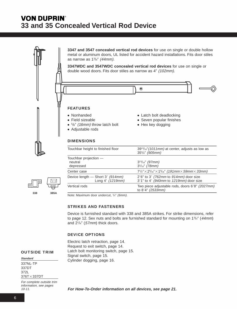
3347 and 3547 concealed ver tical r od de vices for use on single or double hollowmetal or aluminum doors, UL listed for accident hazard installations. Fits door stilesas narrow as 13/49 (44mm).
3347WDC and 3547WDC concealed ver tical r od de vices for use on single ordouble wood doors. Fits door stiles as narrow as 49 (102mm).
FEATURES
● Nonhanded ● Latch bolt deadlocking● Field sizeable ● Seven popular finishes● 5/89 (16mm) throw latch bolt ● Hex key dogging● Adjustable rods
DIMENSIONS
Touchbar height to finished floor 3913/169(1011mm) at center, adjusts as low as355/89 (905mm)
Touchbar projection —neutral 313/169 (97mm)depressed 31/169 (78mm)
Center case 71/29225/169215/169 (191mm259mm233mm)
Device length — Short 38 (914mm) 2869 to 38 (762mm to 914mm) door sizeDevice length — Long 48 (1219mm) 3819 to 48 (940mm to 1219mm) door size
Vertical rods Two piece adjustable rods, doors 6889 (2027mm)to 8849 (2533mm)
Note: Maximum door undercut, 1/49 (6mm).
STRIKES AND FASTENERS
Device is furnished standard with 338 and 385A strikes. For strike dimensions, referto page 12. Sex nuts and bolts are furnished standard for mounting on 13/49 (44mm)and 21/49 (57mm) thick doors.
DEVICE OPTIONS
Electric latch retraction, page 14.Request to exit switch, page 14.Latch bolt monitoring switch, page 15.Signal switch, page 15.Cylinder dogging, page 16.
For Ho w-To-Order inf ormation on all de vices, see page 21.
OUTSIDE TRIMStandar d
337NL-TP337DT372L376T2337DT
For complete outside triminformation, see pages10-11.
338 385A
33 and 35 Concealed Vertical Rod De vice T
7
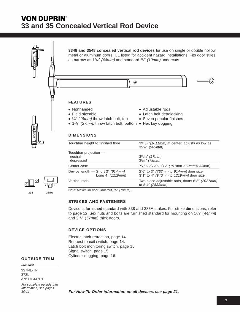
3348 and 3548 concealed ver tical r od de vices for use on single or double hollowmetal or aluminum doors, UL listed for accident hazard installations. Fits door stilesas narrow as 13/49 (44mm) and standard 3/49 (19mm) undercuts.
FEATURES
● Nonhanded ● Adjustable rods● Field sizeable ● Latch bolt deadlocking● 3/49 (19mm) throw latch bolt, top ● Seven popular finishes● 11/29 (37mm) throw latch bolt, bottom ● Hex key dogging
DIMENSIONS
Touchbar height to finished floor 3913/169(1011mm) at center, adjusts as low as355/89 (905mm)
Touchbar projection —neutral 313/169 (97mm)depressed 31/169 (78mm)
Center case 71/29225/169215/169 (191mm259mm233mm)
Device length — Short 38 (914mm) 2869 to 38 (762mm to 914mm) door sizeDevice length — Long 48 (1219mm) 3819 to 48 (940mm to 1219mm) door size
Vertical rods Two piece adjustable rods, doors 6889 (2027mm)to 8849 (2533mm)
Note: Maximum door undercut, 3/49 (19mm).
STRIKES AND FASTENERS
Device is furnished standard with 338 and 385A strikes. For strike dimensions, referto page 12. Sex nuts and bolts are furnished standard for mounting on 13/49 (44mm)and 21/49 (57mm) thick doors.
DEVICE OPTIONS
Electric latch retraction, page 14.Request to exit switch, page 14.Latch bolt monitoring switch, page 15.Signal switch, page 15.Cylinder dogging, page 16.
For Ho w-To-Order inf ormation on all de vices, see page 21.
OUTSIDE TRIMStandar d
337NL-TP372L376T2337DT
For complete outside triminformation, see pages10-11.
338 385A

33 and 35 Fire Exit Concealed Vertical Rod Device T
8
3347-F and 3547-F fire exit concealed vertical rod devices for use on 88288(2438mm22438mm) double metal doors, UL listed for 3 hour fire labeledinstallations. Fits door stiles as narrow as 31/29 (89mm).
3347WDC-F and 3547WDC-F fire exit concealed vertical rod devices for useon 8829839 (2438mm22819mm) double wood doors, UL listed for 90 minute firelabeled installations. Fits door stiles as narrow as 31/29 (89mm).
Less Bottom Rod – LBRLBR option is available, using a spring loaded auxiliary latch bolt installed in thelower door edge. When exposed to heat the auxiliary latch bolt releases, keeping thedoors in alignment and closed during a fire. UL listed 3 hours double egress doors,90 minutes doors swinging same direction, and 20 minute wood doors.
FEATURES
● Nonhanded ● Adjustable rods● Field sizeable ● Latch bolt deadlocking● 5/89 (16mm) throw latch bolt ● Seven popular finishes
DIMENSIONS
Touchbar height to finished floor 3913/169(1011mm) at center, adjusts as low as355/89 (905mm)
Touchbar projection —neutral 313/169 (97mm)depressed 31/169 (78mm)
Center case 71/29225/169215/169 (191mm259mm233mm)
Device length — Short 38 (914mm) 2869 to 38 (762mm to 914mm) door sizeDevice length — Long 48 (1219mm) 3819 to 48 (940mm to 1219mm) door size
Vertical rods 3/89 (10mm) round tubingNote: Maximum door undercut, 1/49 (6mm).
STRIKES AND FASTENERS
Device is furnished standard with 338 and 385A strikes. For strikedimensions, refer to page 12. Sex nuts and bolts are furnished standard formounting on 13/49 (44mm) and 21/49 (57mm) thick doors.
DEVICE OPTIONS
Electric latch retraction, page 14.Request to exit switch, page 14.Latch bolt monitoring switch, page 15.Signal switch, page 15.Cylinder dogging, page 16.
For How-To-Order information on all devices, see page 21.
OUTSIDE TRIMStandard
337NL-TP372L376T2337DT
For complete outside triminformation, see pages10-11.
338 385A

33 and 35 Fire Exit Concealed Vertical Rod De vice T
9
3348-F and 3548-F fire e xit concealed ver tical r od de vices for use on 882108(2438mm22540mm) double metal doors, UL listed for 3 hour fire labeledinstallations. Fits door stiles as narrow as 31/29 (89mm) and standard 3/49 (19mm)undercuts.
FEATURES
● Nonhanded ● Latch bolt deadlocking● Field sizeable ● Seven popular finishes● 3/49 (16mm) throw latch bolt, top ● 11/29 (37mm) throw latch bolt, bottom● Adjustable rods
DIMENSIONS
Touchbar height to finished floor 3913/169(1011mm) at center, adjusts as low as355/89 (905mm)
Touchbar projection —neutral 313/169 (97mm)depressed 31/169 (78mm)
Center case 71/29225/169215/169 (191mm259mm233mm)
Device length — Short 38 (914mm) 2869 to 38 (762mm to 914mm) door sizeDevice length — Long 48 (1219mm) 3819 to 48 (940mm to 1219mm) door size
Vertical rods 3/89 (10mm) round tubingNote: Maximum door undercut, 3/49 (19mm).
STRIKES AND FASTENERS
Device is furnished standard with 338 and 385A strikes. For strike dimensions, referto page 12. Sex nuts and bolts are furnished standard for mounting on 13/49 (44mm)and 21/49 (57mm) thick doors.
DEVICE OPTIONS
Electric latch retraction, page 14.Request to exit switch, page 14.Latch bolt monitoring switch, page 15.Signal switch, page 15.Cylinder dogging, page 16.
For Ho w-To-Order inf ormation on all de vices, see page 21.
OUTSIDE TRIMStandar d
337NL-TP372L376T2337DT
For complete outside triminformation, see pages10-11.
338 385A

01 02 02 03 03 03 05/06 08/09 11/12Exit Only Pull When Pull When Key Retracts Key Retracts Key Retracts NL- Push Button Key Locks Key Locks
Dogged Dogged Latchbolt Latchbolt Latchbolt Operates With Lever ThumbturnFunction Key Only
TP - Key LocksPush Button
333DT 3308DT 334 3308NL 334@Pull 333NL-TP 370L 370T, 374T,376T▲▲
Trim Numberand Dimensions
Device/TrimCenter LineTo Finished Floor
Projection — 27/169 (62mm) 21/169 (62mm) 15/169 (24mm) 21/169 (52mm) 25/89 (67mm) 23/49 (70mm) 25/89 (67mm) 113/169 (46mm)
Panic33EO 33DT 33DT23308DT 33NL-OP 33NL-OP23308NL 33NL-OP2550 33NL-TP 33L 33TL35EO 35DT 35DT23308DT 35NL-OP 35NL-OP23308NL 35NL-OP2550 35NL-TP 35L 35TL
Rim 3913/169 3913/169 A 3913/169 A 3913/169 A 3913/169 A 3913/169 3913/169 A 3913/169 A 3913/169
Ctr. Line (1011mm) (1011mm) (1011mm) (1011mm) (1011mm) (1011mm) (1011mm) (1011mm) (1011mm)B 351/169 B 4115/169 B 351/169 B 3913/169 B 3715/169 B 531/29
(891mm) (1065mm) (891mm) (1011mm) (964mm) (1359mm)
Surface Panic3327EO 3327DT — — — — 3327NL-TP 3327L 3327TL
Mounted3527EO 3527DT 3527NL-TP 3527L 3527TL
Vertical Rod Ctr. Line A 3913/169 — — — — B 3913/169 B 3715/169 B 531/29(1011mm) (1011mm) (964mm) (1359mm)
Panic3347EO 3347DT — — — — 3347NL-TP 3347L 3347TL
Concealed 3547EO 3547DT 3547NL-TP 3547L 3547TL
Ctr. Line A 3913/169 — — — — B 3913/169 B 389/169 B 531/29Vertical Rod(1011mm) (1011mm) (979mm) (1359mm)
Panic3347EO-F — — — — — 3347NL-TP-F 3347L-F 3347TL-F3547EO-F 3547NL-TP-F 3547L-F 3547TL-F
Ctr. Line — — — — B 3913/169 B 389/169 B 531/29Fire Exit (1011mm) (979mm) (1359mm)Concealed
Panic3348EO-F — — — — — 3348NL-TP-F 3348L-F 3348TL-FVertical Rod 3548EO-F 3548NL-TP-F 3548L-F 3548TL-F
Ctr. Line — — — — B 3913/169 B 389/169 B 531/29(1011mm) (979mm) (1359mm)
Additional SNB 2 2 2 1 1 1 2 2 2requirements
CylinderRim — — — Rim Rim Rim Rim Mortise Mortise
TypeVert. Rod — — — — — — Rim Mortise Mortise
RequiredC. V. R. — — — — — — Rim Mortise MortiseFire C. V. R. — — — — — — Rim Mortise Mortise
▲Wood door applications require the use of a 10WDA cover plate.
33 and 35 Trim Selection T
10
AA
A BAB
BBBB
RimLocation
715/329(190mm)
53/89(137mm)
11/49 (32mm)
49(102mm)
71/29(191mm)
31/29(89mm)
111/169(43mm)
11/49(32mm)
53/89(137mm)
111/169(43mm)
15/89(41mm)
M N
M
N
71/29(191mm)
M
N
M N
M
N
M
N
111/29(292mm)
M NM N
M
N
15/89(41mm)
M N
M N
M N
M
N
109(254mm)
M
N
M
N
715/329(190mm)
49(102mm)
M N
M
N
M
N
53/89(137mm)
M
N53/89(137mm)
109(254mm)
A
A

33 and 35 Trim Selection T
11
STANDARD TRIMSERIES 370LLever control has a forged brass 7/89 (22mm) thick escutcheon. Optional lever designsare available.
SERIES 370TThumbturn control has a forged brass 7/89 (22mm) thick escutcheon. Often used with333/337DT or 550 pull trim.
SERIES 333/337Heavy aluminum extrusion body with forged brass pull handle. Available functions:333DT for rim and surface vertical rod, 337DT for concealed vertical rod, 333NL-TPfor rim and surface vertical rod, and 337NL-TP for concealed vertical rod.
SERIES 334Heavy aluminum forged 15/169 (24mm) thick cylinder mount. Often used with333/337DT or 550 pull trim. Cylinder must be ordered separate.
OPTIONAL TRIMSERIES 550Heavy aluminum brackets with 109 (254mm) stainless steel pull bar. DT function only.
3308 SERIES TRIM3308 series trim is available for 33 rim device applications. Available for NL or DToperation. Not recommended for double doors using 5554 or 5754 mullions. Use trimsuffix, example 33NL-OP23308NL.
SERIES 392-6Offset pull throughbolts to 33/35 exit device, 3/49 (19mm) solid brass wire. US26Dfinish only.
LEVER DESIGN OPTIONS
#01 #02 #03 #06 (Std.) #07 #12 #17
To or der, specify:1. Use suffix lever number, example 3327L203.
OPERATION OPTIONS — 370 SERIES LEVER AND THUMBTURN
Standard operation, key Night latch available Blank escutcheon, leverlocks and unlocks lever using the NL cylinder always active. Use BEor thumbturn. plate furnished standard, suffix, i.e., 370L-BE,
lever retracts latch for 372L-BE.NL function.
333/337NL/TP
370L 370T
334
392-6
550
3308
02
333/337DT

STRIKES FOR RIM DEVICES
299 1408 1409 — Blade Stop 1410 — Integral Stop
Projection 13/169 (21mm) One per pair of doors Projection 1/29 (13mm) Projection 1/29 (13mm)
1606 1609
Projection 3/89 (10mm) For rim/vertical rod combination — consult factory
STRIKES FOR VERTICAL ROD DEVICES
284L-4 260U — Flush Transom Only 265 266
Projection 3/89 (10mm) Projection 3/89 (10mm) Projection 3/49 (19mm) Projection 1 1/49 (21mm)
299 304L 338 385A
Projection 13/169 (21mm) Mortise 13/169 (21mm) Projection 5/89 (16mm) Mortise 2 1/29 (64mm)
33 and 35 Strike/Stile Information T
12
3335
33273527Latch Retraction
3347, 33483547, 35483347WDC3547WDC
3347-F, 3348-F3547-F, 3548-F3347WDC-F3547WDC-F
Device Standard OptionalType Single door Double door Single door Double door
Strike Stile
1409 13/49 (44mm)
266 (Top) 1¾9 (44mm)304L (Bottom)248L-4 (Bottom)
338 (Top) 2½9 (64mm)385A (Bottom)
— —
Strike w/Mullion* Stile
140825754 13/49 (44mm)
266 (Top) 1¾9 (44mm)304L (Bottom)248L-4 (Bottom)
338 (Top 1¾9 (44mm)385A (Bottom)
338 (Top) 3½9 (89mm)385A (Bottom)
Strike Stile Strike w/Mullion* Stile
299 2¾9 (70mm) 29925654 25/89 (67mm)
1410 1¾9 (44mm) 29924954 35/169 (84mm)
1606 2½9 (64mm) 160621654 2¾9 (70mm)266/299 (Top) 31/89 (79mm) 266/299 (Top) 21/89 (54mm)385A (Bottom) 385A (Bottom)
260U/266 (Top) 21/89 (54mm) 260U/266 (Top) 13/49 (44mm)385A (Bottom) 385A (Bottom)
304L (Bottom) 2½9 (64mm) 304L (Bottom) 1¾9 (44mm)
— — 304L (Bottom) 3½9 (89mm)
*Mullion information — Refer to the General and Auxiliary Catalog.
STRIKE APPLICATION/MINIMUM STILE
17/89(48mm)
11/49(32mm)
7/329(6mm)
7/89(22mm)
1/49(6mm)
33/169(81mm)
27/89(73mm)
31/49(83mm)
M
N
27/89(73mm)
M
M
NNO P 13/89
(35mm)
13/89(35mm)
3/89(10mm)
3/169(5mm)
O P13/89
(35mm)
5/89(15mm)
29/169(63mm)
3/169(5mm)
M
M M
M
M
M
M
M
M
M M
M
N
N
11/49(32mm)
11/49(32mm)
1/49(6mm)
13/169 (21mm)
M
M
M
M
M
M
N
37/169(87mm)
M
N
M
N
M
N
23/89(60mm)
M
M
3/169(5mm)
1/29(13mm)
3/169(5mm)
1/29(13mm)
17/89(48mm)
11/169(27mm)
11/169(27mm)
3/89(10mm)
13/49(44mm)
17/89(48mm)
M
M
21/29(64mm)
M
M
M
N
9/169(14mm)
21/29(64mm)
M
M
M
N
15/89(41mm)
27/89(73mm)
M
M
M
M
M
M
M
M
N
11/49(32mm)
3/169(5mm)
13/169(21mm)
M
M 17/89(48mm)
M
N
15/89(41mm)
M
M 17/89(48mm)
M
N
29(51mm)
M
M 23/49(70mm)
M
N
33 and 35 Options T
13
ALK EXIT ALARM KIT
The ALK battery alarm kit is a simple yet effectiveway to monitor the use of an exit device. While still ameans of egress, the unit contains an internal horn,when the touchbar is depressed, the horn sounds toprovide an audible means of signaling that theopening has been violated.
The key switch uses a standard 11/49 (32mm) mortisecylinder. The unit operates on one standard 9-volttransistor battery. When the battery is weak the hornwill emit an intermittent signal.
Alarm kits are available with a choice of two switchkits, S1 or S2. S1 monitors the touchpad and isfurnished standard, S2 optional latchbolt monitoringis recommended for use with surface vertical rod exitdevices. Specify ALK-S2.
The ALK is available in two styles, 33/99ALK,grooved cover and 35/98ALK, smooth cover.
The ALK includes “EMERGENCY EXIT ONLY.ALARM WILL SOUND” decal for application on door.
Minim um Door Siz es
388 (914mm) 488 (1219mm)Device Length Length
33/35 2899 (838mm) 3839 (991mm)
3327/3527 2889 (813mm) 3829 (966mm)
3347/3347-F/3547/3547-F 2889 (813mm) 3829 (966mm)
3348/3348-F/3547/3547-F 2889 (813mm) 3829 (966mm)
PS9 POWER SUPPLY
The PS9 is an AC power supply that provides 9VDC power to operate the ALK alarm kit. The unitwill power one or two alarm kits. Included is a 9-voltsealed battery that provides backup power in caseof an AC power failure. PS9 must be orderedseparately.
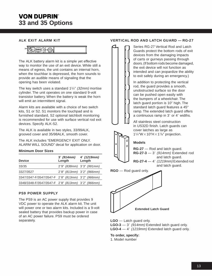
VERTICAL ROD AND LATCH GUARD — RG-27
Series RG-27 Vertical Rod and LatchGuards protect the bottom rods of exitdevices from the damaging impactsof carts or gurneys passing throughdoors. (If bottom rods become damaged,the exit device will not function asintended and can jeopardize the abilityto exit safely during an emergency.)
In addition to protecting the verticalrod, the guard provides a smooth,unobstructed surface so the doorcan be pushed open easily withthe bumpers of a wheelchair. Thelatch guard portion is 109 high. Thestandard latch guard features a 45°ramp. The extended latch guard offersa continuous ramp in 38 or 48 widths.
All stainless steel construction in US32D finish. Latch guards cancover latches as large as11/49W2109H217/89 projection.
Models
RG-27 — Rod and latch guard.RG-27-3 — 38 (914mm) Extended rod
and latch guard.RG-27-4 — 48 (1219mm) Extended rod
and latch guard.
RGO — Rod guard only.
LGO — Latch guard only.LGO-3 — 38 (914mm) Extended latch guard only.LGO-4 — 48 (1219mm) Extended latch guard only.
To or der, specify:1. Model number
Extended Latc h Guar d
33 and 35 Options T
14
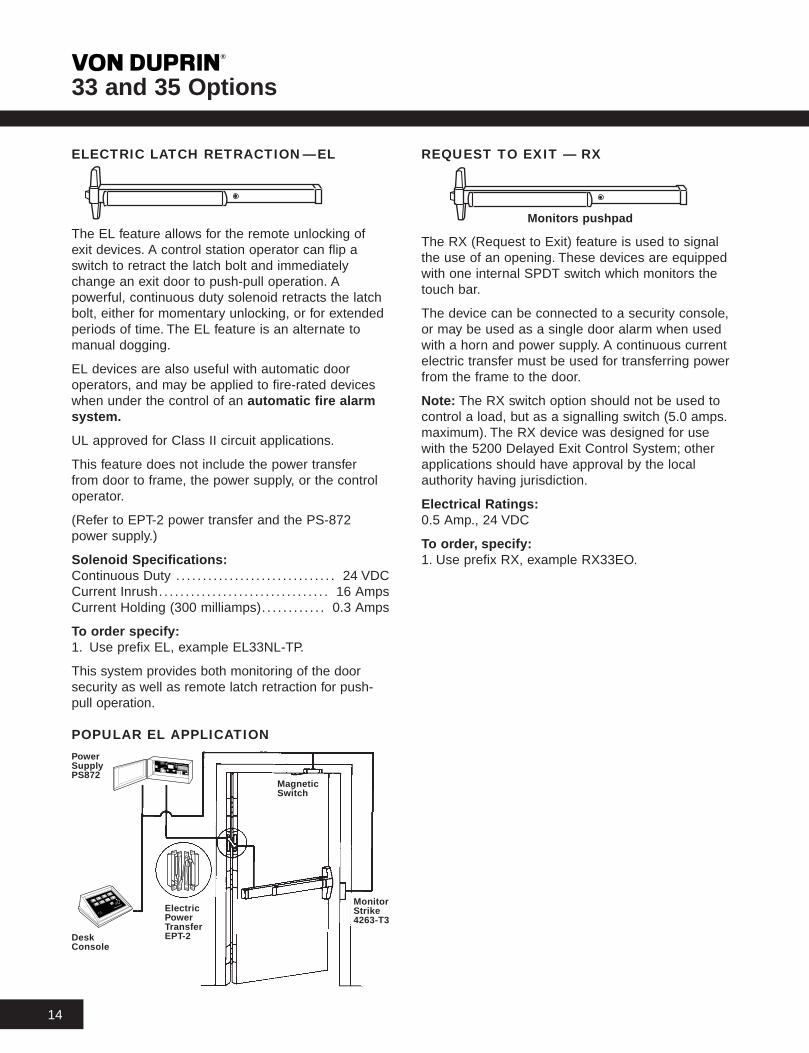
ELECTRIC LATCH RETRACTION—EL
The EL feature allows for the remote unlocking ofexit devices. A control station operator can flip aswitch to retract the latch bolt and immediatelychange an exit door to push-pull operation. Apowerful, continuous duty solenoid retracts the latchbolt, either for momentary unlocking, or for extendedperiods of time. The EL feature is an alternate tomanual dogging.
EL devices are also useful with automatic dooroperators, and may be applied to fire-rated deviceswhen under the control of an automatic fire alarmsystem.
UL approved for Class II circuit applications.
This feature does not include the power transferfrom door to frame, the power supply, or the controloperator.
(Refer to EPT-2 power transfer and the PS-872power supply.)
Solenoid Specifications:Continuous Duty . . . . . . . . . . . . . . . . . . . . . . . . . . . . . . 24 VDCCurrent Inrush. . . . . . . . . . . . . . . . . . . . . . . . . . . . . . . . 16 AmpsCurrent Holding (300 milliamps). . . . . . . . . . . . 0.3 Amps
To or der specify:1. Use prefix EL, example EL33NL-TP.
This system provides both monitoring of the doorsecurity as well as remote latch retraction for push-pull operation.
POPULAR EL APPLICATIONPowerSuppl yPS872
DeskConsole
ElectricPowerTransf erEPT-2
MagneticSwitc h
MonitorStrike4263-T3
REQUEST TO EXIT — RX
Monitor s pushpad
The RX (Request to Exit) feature is used to signalthe use of an opening. These devices are equippedwith one internal SPDT switch which monitors thetouch bar.
The device can be connected to a security console,or may be used as a single door alarm when usedwith a horn and power supply. A continuous currentelectric transfer must be used for transferring powerfrom the frame to the door.
Note: The RX switch option should not be used tocontrol a load, but as a signalling switch (5.0 amps.maximum). The RX device was designed for usewith the 5200 Delayed Exit Control System; otherapplications should have approval by the localauthority having jurisdiction.
Electrical Ratings:0.5 Amp., 24 VDC
To or der, specify:1. Use prefix RX, example RX33EO.

33 and 35 Options T
15
SIGNAL SWITCH — SS
Monitor s pushpad and latc h bolt
The SS feature is used to signal the unauthorizeduse of an opening. These devices are equipped withtwo internal SPDT switches. One switch monitorsboth the touch bar and the latch bolt assembly,making the latch bolt tamper resistant, for positivesecurity. An additional SPDT switch is connected tothe 11/49 (32mm) mortise master keyable cylinder foralarm “bypass.”
The device can be connected to a security console,or may be used as a single door alarm when usedwith a horn and power supply. A continuous currentelectric transfer must be used for transferring powerfrom the frame to the door.
Electrical Ratings:Each switch rated 0.5 Amp. 24 VDC
To or der, specify:1. Use prefix SS, example SS33NL-TP.2. Finish, see page 19 (touch pad finish is US32D
only).3. Handing LHR or RHR.4. Size 38 or 48 (914mm or 1219mm).
Unauthorized use of this opening will activate thelocal horn. The key switch permits inhibiting thissystem for authorized entry.
POPULAR SS APPLICATION
EMERGENCY EXIT ONLYPUSH TO OPEN AND SOUND ALARM
HornL1900F
ElectricFeed-thr oughHing e
MagneticSwitc h
PowerSuppl yPS861
KeySwitc h(exterior)SS903
LATCH BOLT MONITORING — LX
The LX feature is used to signal the use of anopening. These devices are equipped with oneinternal SPDT switch which monitors the latch bolt.
The device can be connected to a security console,or may be used as a single door alarm when usedwith a horn and power supply. A continuous currentelectric transfer must be used for transferring powerfrom the frame to the door.
Note: The LX switch option should not be used tocontrol a load, but as a signalling switch (5.0 amps.maximum).
Electrical Ratings:0.5 Amp., 24 VDC
To or der, specify:1. Use prefix LX, example LX33EO.

33 and 35 Accessories T
16
SIGNAL SWITCH TRIM — SS-333
The SS-333 outside trim contains aSPDT switch for monitoring theoperation of the outside push button.This switch may be used as amonitoring device or as an alarminhibit for passage through amonitored door without causing analarm.
This trim is designed for use on aluminum or hollowmetal doors. The wiring in aluminum doors must berouted through the door using the stile and top rail.
An electric feed-through hinge may be used totransfer power from the frame to the door.
The SS-333 trim is available for use with 33 rim or3327 surface mounted vertical rod devices. Notrecommended for NL function. Cylinder not included.
Electrical Ratings:0.5 Amps. 24 VDC
To or der, specify:1. SS-333, R (rim) or V (vertical rod).2. Finish, see page 19.3. Handing, see page 22.
CYLINDER DOGGING — CD
Cylinder dogging is available onall 33/35 devices to replace thestandard hex key dogging. Unitrequires a standard 11/49 (32mm)mortise cylinder.
To or der, specify:1. Use prefix CD, example CD33NL-TP.
CYLINDER DOGGING KIT — CDK
For field conversions, a cylinder dogging conversionkit is available.
Order: 33/99CDK or 35/98CDK, specify finish.
HEX KEY DOGGING KIT — HDK
For field conversion, a hex key dogging conversionkit is available.
Order: 33/99HDK or 35/98HDK, specify finish.
ELECTRICAL POWER TRANSFER
The EPT provides a means to transfer power fromthe frame to the door stile in EL33/35 13/49 (44mm)thick door applications; up to 59 (127mm) butt hinges— 1807 opening, 3/49 (19mm) offset privots — 1807opening, 51/29 (140mm) butt hinges — 1307 opening,and 69 (152mm) butt hinges — 1107 opening. Whenthe door is closed, the unit is concealed and tamperresistant.
Two models are available, EPT-2 (two 18 gaugewires) and EPT-10 (ten 24 gauge wires).
UL Fire Listed for use with listed rim, and vertical rodfire devices with electric latch retraction feature.
Dimensions
Housing 99211/49211/29 (229mm232mm238mm)
Conductors Two 18 AWG., ten 24 AWG
Rating EPT-2, 2 Amps. at 24 VDC, 16 Amp.maximum surge EPT-10, 2 Amp. at 24 VDC
To or der, specify:1. EPT-2 or EPT-10.2. Finish, SP28 (sprayed aluminum) or SP313
(sprayed duranodic).

33 and 35 Accessories T
17
POWER SUPPLIES
The series PS861 power supply is designed forelectric locking or monitoring on single or doubledoor applications. The output power is field selec-table for either 24 VDC @ 1 ampere or 12 VDC @ 2ampere. Standard input 120 VAC @ 0.6 ampere and240 VAC @ 0.3 ampere available. The terminal blockwill accept up to 14 gauge stranded wire.
The gray enclosure is 1092109249 (254mm2254mm2102mm), has a hinged cover, and isconstructed of heavy 19 gauge steel. Six 1/29 (13mm)knockout holes are provided for conduit connection.
Options include keylock cover and sealed leadacid battery pack. The pair of batteries will provideback-up power for three hours at full load or sevenhours at half load. Batteries will automaticallyrecharge when failed power is restored.
FOUR MODELS:
PS861 Standard supplyPS861K Standard supply
with keylock coverPS861B Battery backupPS861BK Battery backup and
keylock cover
DUMMY PUSH BAR
The 330 dummy push bar is designed as acompanion unit for all 33 devices. The 350 dummypush bar is a companion unit for all 35 devices. Thetouch bar is rigid or nonfunctioning. A push/pulloperation can be accomplished by using 337DT or370L-DT trim.
To order, specify:1. 330 or 350.2. Size 38 or 48 (914mm or 1219mm).3. Finish, see page 19.
The series PS871 power supply is designed tooperate electric locking or monitoring exit devices,except EL (electric latch retraction). The regulatedoutput power is field selectable for either 24 VDC @2 ampere or 12 VDC @ 4 ampere. Standard input120 VAC @ 1.0 ampere or 240 VAC @ 0.5 ampereis available.
The gray enclosure is 57/892121/29 wide 259 deep(149mm2318mm2127mm), has a hinged cover,and is constructed of heavy 19 gauge steel. Three1/2923/49 (13mm219mm) knockout holes areprovided for conduit connection. The terminal blockwill accept up to 14 gauge wire.
Option — An 871-2 circuit card is available forfield installation. The 871-2 converts the PS871 tothe equivalent PS872 and will operate two ELdevices.
The series PS872 power supply is designed tooperate two EL (electric latch retraction) exit devicesand replaces the MPB842. The regulated outputpower is 24 VDC @ 2 ampere. Standard input 120VAC @ 1.0 ampere or 240 VAC @ 0.5 ampere isavailable.
The gray enclosure is 57/892121/29 wide 259 deep(149mm2318mm2127mm), has a hinged cover,and is constructed of heavy 19 gauge steel. Three1/2923/49 (13mm219mm) knockout holes areprovided for conduit connection. The terminal blockwill accept up to 14 gauge wire.
Option — An 871-2 circuit card is available for fieldinstallation. The 871-2 is a two zone controller cardand, when added to the PS872, will operate four ELexit devices. It replaces the RBS884.
To Order, Specify:1. Model number
UL ListedClass 2, Power SupplyUL1012UL1310
Standard
UL ListedClass 2, Power SupplyUL1012UL1310
With keylockand batteries

33 and 35 Ad ditional Inf ormation T
18
ANSI GRADE, TYPE & FUNCTION
Function Grade 1, Type 4 Grade 1, Type 5 Grade 1, Type 6 & 8 Grade 1, Type 7
3347EO, 3347EO-F 3347WDC-EO, 3547WDC-EO01 33EO, 35EO 3327EO, 3527EO 3547EO, 3547EO-F
3348EO, 3348EO-F3548EO, 3548EO-F
02 33DT, 35DT 3327DT, 3527DT 3347DT, 3547DT 3347WDC-DT, 3547WDC-DT3348DT, 3548DT
03 33NL-OP, 35NL-OP — — —
3347NL-TP, 3347NL-TP-F
05-06 33NL-TP, 35NL-TP 3327NL-TP, 3527NL-TP 3547NL-TP, 3547NL-TP-F 3347WDC-NL-TP3348NL-JP, 3348NL-TP-F 3547WDC-NL-TP3548NL-TP, 3548NL-TP-F
3347L, 3347L-F
08-09 33L, 35L 3327L, 3527L 3547L, 3547L-F 3347WDC-L, 3547WDC-L3348L, 3348L-F3548L, 3548L-F
3347TL, 3347TL-F
11-12 33TL, 35TL 3327TL, 3527TL 3547TL, 3547TL-F 3347WDC-TL, 3547WDC-TL3348TL, 3348TL-F3548TL, 3548TL-F
UL LISTED — FIRE EXIT HARDWARE LABEL/OPENING SIZE
Doub le Door
Exit De vice Same Direction Doub le Egress
3347-F 90 Min. 88288 3 Hour 88288
3547-F 90 Min. 88288 3 Hour 88288
3347-F-WDC 90 Min. 8829839 —
3547-F-WDC 90 Min. 8829839 —
3348-F 90 Min. 882108 3 Hour 882108
3548-F 90 Min. 882108 3 Hour 882108
LHR RHR
Left HandOrientation
Right HandOrientation
(Left hand reverse) (Right hand reverse)
Outside
HANDING
CYLINDERSCylinders are not furnished with device or trim and must be specified when ordering. Rim, surface vertical rod,and concealed vertical rod exit devices use rim type cylinders. Mortise lock exit devices and series 370 controlsuse mortise type cylinders.
Mor tise – 3215 (Sc hlage B502-191 cam)
A
B
1 5/32''(29mm)
1 1/4''(32mm)
5/16 – 3/8'' (8 – 9mm)
11/16 – 3/4'' (17 – 19mm)
A
B
1 5/32''(29mm)
1 1/4''(32mm)
5/64'' max.(2mm)
1/4'' max.(6mm)
Rim – 3216

33 and 35 Ad ditional Inf ormation T
19
FINISHES
Color US Number BHMA Number A, B, C, D, G E F
Brass, Polished US3 BHMA605 Plated Brass, Polished US3, BHMA605 Buffed Anodized
Brass, Dull US4 BHMA Anodized Brass, Dull US4, BHMA606 Anodized
Bronze, Dull US10 BHMA688 Anodized Bronze, Dull US10, BHMA612 Anodized
Chrome, Polished US26 BHMA625 Plated Stainless Steel, Polished US32, BHMA629 Buffed Anodized
Chrome, Dull US26D BHMA626 Plated Stainless Steel, Satin US32D, BHMA630 Anodized
Aluminum, Anodized US28 BHMA628 Anodized Stainless Steel, Satin US32D, BHMA630 Anodized
Duranodic Dark Bronze 313 — Anodized Walnut grain vinyl Anodized
Touc h Bar Option s —Knurled—Black vinyl—Embossed “Push”, bronze or stainless steel
DIMENSIONS
71/29(191mm)
21/49(57mm)
215/169(75mm)
115/169(49mm)
339 (838mm)489 (1118mm)
189 (457mm)249 (810mm)
Neutral: 313/169 (97mm)Depressed: 31/169 (75mm)
215/169(75mm)
A — Lock stile cover–top
D — Touch bar end capE — Touch bar
B — Lock stile housing
C — Lock stile cover–bottomF — Mechanism housing
G — Mechanism end cap

33 and 35 Ad ditional Inf ormation T
20
POPULAR DOUBLE DOOR APPLICATIONS
Two rim devices with mullion — same direction
Two vertical rods — double egress
Two vertical rod devices — same direction (do not use withoverlapping astragal)

33 and 35 Ad ditional Inf ormation T
21
HOW-TO-ORDER INFORMATION
Rim de vices, specify:1. Exit device model number with trim selection.
Examples: 33EO (exit only with no outside trim).33NL-OP (includes standard 334 trim). 33NL-OP23308NL (includes the optional 3308NL trim).
2. Size 48 (1219mm) for door sizes 3819 (940mm) to48 (1219mm). Size 38 (914mm) for door sizes 2869(792mm) to 38 (914mm) is shipped standard.
3. Door thickness if other than 13/49 (44mm).4. Door and frame material if other than hollow
metal.5. Finish, see page 19.6. Handing required on “L,” “SS,” or “TP-BE.” Specify
LHR or RHR. See page 18.
Vertical r od de vices, specify:1. Exit device model number with trim selection.
Example: 3327EO (exit only with no outsidetrim). 3327NL-OP (includes standard 334 trim).3327NL-OP23308NL (includes the optional3308NL trim).
2. Size 48 (1219mm) for door sizes 3819 (940mm) to48 (1219mm). Size 38 (914mm) for door sizes 2869(792mm) to 38 (914mm) is shipped standard.
3. Door thickness if other than 13/49 (44mm).4. Door height if greater than 78 (2134mm),
extension rods must be ordered.5. Door and frame material if other than hollow
metal.6. Finish, see page 19.7. Handing required on “L,” “SS,” or “TP-BE.” Specify
LHR or RHR. See page 18.
Pullman latc hes are optional for 33/3527 devices.Latchbolts remain extended at all times. Specify“Pullman Latch” when required.

33 and 35 Ad ditional Inf ormation T
22
NOMENCLATURE
EL 33 47 WDC NL-TP -F -BE
CD — Cylinder DoggingEL — Electric Latch RetractionES — Electric Strike (obsolete)LX — Latch Bolt MonitoringPL — Pullman LatchRX — Request to ExitSS — Signal Switch
33 — Series 3335 — Series 35
None — Rim Device27 — Surface Mounted Vertical Rod Device37 — Use 47-F (37 obsolete)47 — Concealed Vertical Rod Device48 — Concealed Vertical Rod Device
WDC — Wood Door Concealed
DT — Dummy TrimEO — Exit OnlyL — LeverNL-OP — Night Latch Cylinder AssemblyNL-TP — Night Latch/ThumbpieceTL — Turn Lever
F — Fire Exit Device
BE — Blank Escutcheon (trim always operable)LBR — Less Bottom Rod