32199033 production engineering module 2
TRANSCRIPT

8/9/2019 32199033 Production Engineering Module 2
http://slidepdf.com/reader/full/32199033-production-engineering-module-2 1/60
ME- 305ME- 305
MANUFACTURING PRPOCESSES - IIMANUFACTURING PRPOCESSES - II
05/30/10 1
Module 2
Lecture 3 - Cutting Tools
WECWEC

8/9/2019 32199033 Production Engineering Module 2
http://slidepdf.com/reader/full/32199033-production-engineering-module-2 2/60
Cutting
Cutting is the separation of a physical object, ora portion of a physical object, into two portions,through the application of an acutely directedforce.
Cutting is a compressive and shearingphenomenon, and occurs only when the totalstress generated by the cutting implementexceeds the ultimate strength of the material of the object being cut. The simplest applicableequation is stress = force/area: The stress
generated by a cutting implement is directlyproportional to the force with which it is applied,and inversely proportional to the area of contact.Hence, the smaller the area (i.e., the sharper thecutting implement), the less force is needed tocut something

8/9/2019 32199033 Production Engineering Module 2
http://slidepdf.com/reader/full/32199033-production-engineering-module-2 3/60
Cutting tools

8/9/2019 32199033 Production Engineering Module 2
http://slidepdf.com/reader/full/32199033-production-engineering-module-2 4/60
Cutting Tool
Requirements
8/9/2019 32199033 Production Engineering Module 2
http://slidepdf.com/reader/full/32199033-production-engineering-module-2 5/60
Single point cutting
tool – Tool Bit The term tool bit generally refers to a
non-rotary cutting tool used in metallathes, shapers, and planers. Such cutters
are also often referred to by the set-phrase name of single-point cuttingtool. The cutting edge is ground to suit aparticular machining operation and may
be re-sharpened or reshaped as needed. The ground tool bit is held rigidly by a toolholder while it is cutting.

8/9/2019 32199033 Production Engineering Module 2
http://slidepdf.com/reader/full/32199033-production-engineering-module-2 6/60
Various tool bits,carbide inserts andholders

8/9/2019 32199033 Production Engineering Module 2
http://slidepdf.com/reader/full/32199033-production-engineering-module-2 7/60
Single point toolGeometry

8/9/2019 32199033 Production Engineering Module 2
http://slidepdf.com/reader/full/32199033-production-engineering-module-2 8/60
Single point tool
Geometry Back Rake is to help control the direction of thechip, which naturally curves into the work due tothe difference in length from the outer and innerparts of the cut. It also helps counteract thepressure against the tool from the work by pullingthe tool into the work.
Side Rake along with back rake controls the chipflow and partly counteracts the resistance of thework to the movement of the cutter and can beoptimized to suit the particular material being cut.
Brass for example requires a back and side rake of 0 degrees while aluminum uses a back rake of 35degrees and a side rake of 15 degrees.
8/9/2019 32199033 Production Engineering Module 2
http://slidepdf.com/reader/full/32199033-production-engineering-module-2 9/60
Single point tool
Geometry Nose Radius makes the finish of the cutsmoother as it can overlap the previous cut andeliminate the peaks and valleys that a pointedtool produces. Having a radius also strengthens
the tip, a sharp point being quite fragile. All the other angles are for clearance in order
that no part of the tool besides the actual cuttingedge can touch the work. The front clearanceangle is usually 8 degrees while the side
clearance angle is 10-15 degrees and partlydepends on the rate of feed expected.

8/9/2019 32199033 Production Engineering Module 2
http://slidepdf.com/reader/full/32199033-production-engineering-module-2 10/60
Single point tool
Geometry Minimum angles which do the job required are
advisable because the tool gets weaker as theedge gets keener due to the lessening support
behind the edge and the reduced ability toabsorb heat generated by cutting.
The Rake angles on the top of the tool neednot be precise in order to cut but to cutefficiently there will be an optimum angle forback and side rake.

8/9/2019 32199033 Production Engineering Module 2
http://slidepdf.com/reader/full/32199033-production-engineering-module-2 11/60
Tool Geometry

8/9/2019 32199033 Production Engineering Module 2
http://slidepdf.com/reader/full/32199033-production-engineering-module-2 12/60

8/9/2019 32199033 Production Engineering Module 2
http://slidepdf.com/reader/full/32199033-production-engineering-module-2 13/60
Tool Geometry

8/9/2019 32199033 Production Engineering Module 2
http://slidepdf.com/reader/full/32199033-production-engineering-module-2 14/60
Tool Geometry
8/9/2019 32199033 Production Engineering Module 2
http://slidepdf.com/reader/full/32199033-production-engineering-module-2 15/60
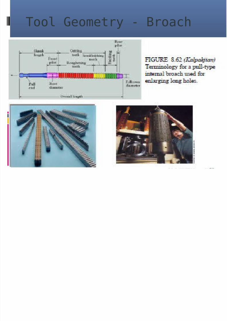
Tool Geometry - Broach

8/9/2019 32199033 Production Engineering Module 2
http://slidepdf.com/reader/full/32199033-production-engineering-module-2 16/60
Tooling hardness andtemperature
8/9/2019 32199033 Production Engineering Module 2
http://slidepdf.com/reader/full/32199033-production-engineering-module-2 17/60
Mill cutters
Milling cutters are cutting toolsused in milling machines ormachining centres. They removematerial by their movement withinthe machine (eg: a ball nose mill) ordirectly from the cutters shape (a
form tool such as a Hobbing cutter).

8/9/2019 32199033 Production Engineering Module 2
http://slidepdf.com/reader/full/32199033-production-engineering-module-2 18/60
Milling Cutters

8/9/2019 32199033 Production Engineering Module 2
http://slidepdf.com/reader/full/32199033-production-engineering-module-2 19/60
Features of a milling
cutter
Milling cutters come in several shapes and many sizes. There is also a choice of coatings, as well as rake angleand number of cutting surfaces.
Shape: Several standard shapes of milling cutter areused in industry today, which are explained in moredetail below.
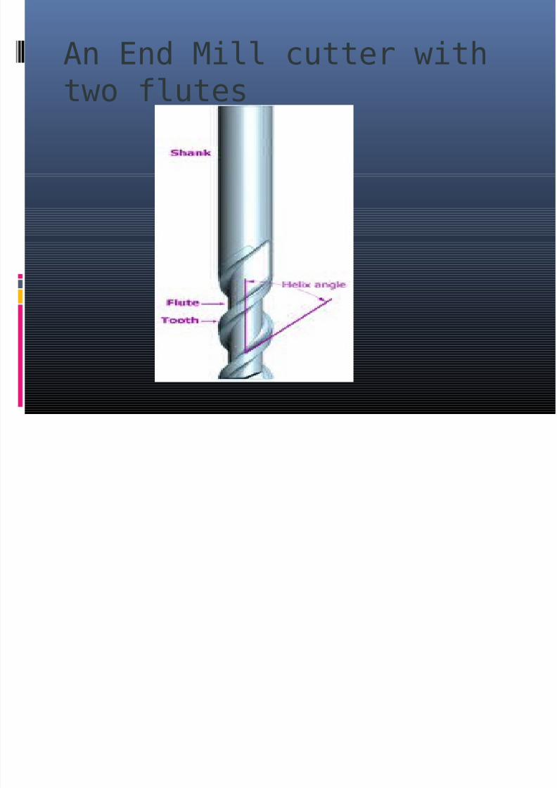
Flutes / teeth: The flutes of the milling bit are thedeep helical grooves running up the cutter, while thesharp blade along the edge of the flute is known as thetooth. The tooth cuts the material, and chips of thismaterial are pulled up the flute by the rotation of thecutter. There is almost always one tooth per flute, butsome cutters have two teeth per flute. Often, the words
flute and tooth are used interchangeably. Milling cuttersmay have from one to many teeth, with 2, 3 and 4being most common. Typically, the more teeth a cutterhas, the more rapidly it can remove material. So, a 4-tooth cutter can remove material at twice the rate of a2-tooth cutter.

8/9/2019 32199033 Production Engineering Module 2
http://slidepdf.com/reader/full/32199033-production-engineering-module-2 20/60
Features of a milling
cutter Helix angle: The flutes of a milling cutter arealmost always helical. If the flutes were straight,the whole tooth would impact the material atonce, causing vibration and reducing accuracyand surface quality. Setting the flutes at anangle allows the tooth to enter the materialgradually, reducing vibration. Typically, finishingcutters have a higher rake angle (tighter helix)to give a better finish.
Center cutting: Some milling cutters can drill
straight down (plunge) through the material,while others cannot. This is because the teeth of some cutters do not go all the way to the centreof the end face. However, these cutters can cutdownwards at an angle of 45 degrees or so.

8/9/2019 32199033 Production Engineering Module 2
http://slidepdf.com/reader/full/32199033-production-engineering-module-2 21/60
Features of a milling
cutter Roughing or Finishing: Different types of cutter areavailable for cutting away large amounts of material, leavinga poor surface finish (roughing), or removing a smalleramount of material, but leaving a good surface finish(finishing). A roughing cutter may have serrated teeth for
breaking the chips of material into smaller pieces. Theseteeth leave a rough surface behind. A finishing cutter mayhave a large number (4 or more) teeth for removingmaterial carefully. However, the large number of flutesleaves little room for efficient swarf removal, so they areless appropriate for removing large amounts of material.

8/9/2019 32199033 Production Engineering Module 2
http://slidepdf.com/reader/full/32199033-production-engineering-module-2 22/60
Features of a milling
cutter Coatings: The right tool coatings can have a great influence on thecutting process by increasing cutting speed and tool life, andimproving the surface finish. Polycrystalline Diamond (PCD) is anexceptionally hard coating used on cutters which must withstandhigh abrasive wear. A PCD coated tool may last up to 100 timeslonger than an uncoated tool. However the coating cannot be used attemperatures above 600 degrees C, or on ferrous metals. Tools formachining aluminium are sometimes given a coating of TiAlN.Aluminium is a relatively sticky metal, and can weld itself to theteeth of tools, causing them to appear blunt. However it tends not tostick to TiAlN, allowing the tool to be used for much longer inaluminium.
Shank: The shank is the cylindrical (non-fluted) part of the toolwhich is used to hold and locate it in the tool holder. A shank may be
perfectly round, and held by friction, or it may have a Weldon Flat,where a grub screw makes contact for increased torque without thetool slipping. The diameter may be different from the diameter of thecutting part of the tool, so that it can be held by a standard toolholder.
8/9/2019 32199033 Production Engineering Module 2
http://slidepdf.com/reader/full/32199033-production-engineering-module-2 23/60
An End Mill cutter with
two flutes
8/9/2019 32199033 Production Engineering Module 2
http://slidepdf.com/reader/full/32199033-production-engineering-module-2 24/60
Types of milling cutters
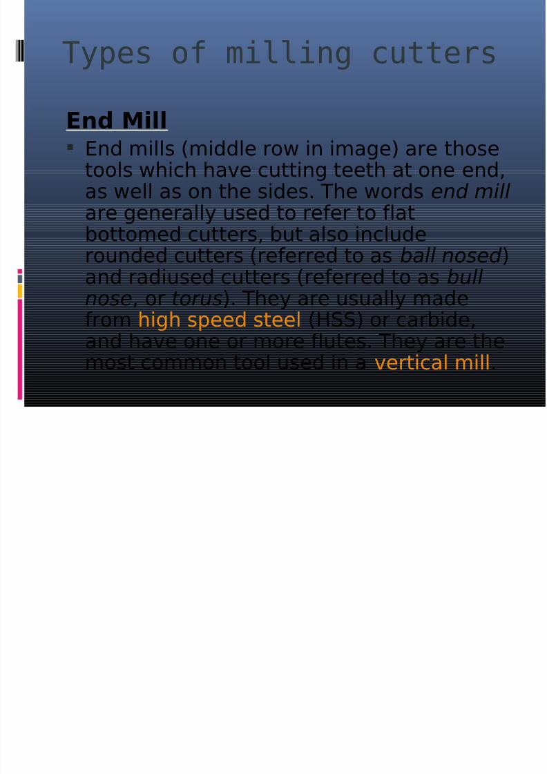
End Mill End mills (middle row in image) are those
tools which have cutting teeth at one end,
as well as on the sides. The words end mill are generally used to refer to flatbottomed cutters, but also includerounded cutters (referred to as ball nosed )and radiused cutters (referred to as bullnose, or torus). They are usually madefrom high speed steel (HSS) or carbide,and have one or more flutes. They are themost common tool used in a vertical mill.

8/9/2019 32199033 Production Engineering Module 2
http://slidepdf.com/reader/full/32199033-production-engineering-module-2 25/60
Types of milling cutters
Slot drill Slot drills (top row in image) are generally
two (occasionally three or four) fluted cuttersthat are designed to drill straight down into
the material. This is possible because thereis at least one tooth at the centre of the endface. They are so named for their use incutting keyway slots. The term slot drill isusually assumed to mean a two fluted, flat
bottomed end mill if no other information isgiven. Two fluted end mills are usually slotdrills, three fluted sometimes are not, andfour fluted usually are not.

8/9/2019 32199033 Production Engineering Module 2
http://slidepdf.com/reader/full/32199033-production-engineering-module-2 26/60
Types of milling cutters
Roughing end mill Roughing end mills quickly remove large
amounts of material. This kind of end millutilizes a wavy tooth form cut on the
periphery. These wavy teeth form manysuccessive cutting edges producing manysmall chips, resulting in a relatively roughsurface finish. During cutting, multipleteeth are in contact with the workpiece
reducing chatter and vibration. Rapid stockremoval with heavy milling cuts issometimes called hogging. Roughing endmills are also sometimes known as rippingcutters.

8/9/2019 32199033 Production Engineering Module 2
http://slidepdf.com/reader/full/32199033-production-engineering-module-2 27/60
Types of milling cutters
Ball nose cutter
Ball nose cutters (lower row in image) aresimilar to slot drills, but the end of the
cutters are hemispherical. They are idealfor machining 3-dimensional contouredshapes in machining centres, for examplein moulds and dies. They are sometimescalled ball mills in shop-floor slang,despite the fact that that term also hasanother meaning. They are also used toadd a radius between perpendicular facesto reduce stress concentrations.

8/9/2019 32199033 Production Engineering Module 2
http://slidepdf.com/reader/full/32199033-production-engineering-module-2 28/60

8/9/2019 32199033 Production Engineering Module 2
http://slidepdf.com/reader/full/32199033-production-engineering-module-2 29/60
Types of milling cutters
Slab Mill
Slab mills are used either bythemselves or in gang milling operations on manual horizontal oruniversal milling machines to machinelarge broad surfaces quickly. They
have been superseded by the use of carbide-tipped face mills which arethen used in vertical mills ormachining centres.
8/9/2019 32199033 Production Engineering Module 2
http://slidepdf.com/reader/full/32199033-production-engineering-module-2 30/60

8/9/2019 32199033 Production Engineering Module 2
http://slidepdf.com/reader/full/32199033-production-engineering-module-2 31/60
Types of milling cutters
Involute gear cutter
There are 8 cutters (excluding the
rare half sizes) that will cut gearsfrom 12 teeth through to a rack(infinite diameter).

8/9/2019 32199033 Production Engineering Module 2
http://slidepdf.com/reader/full/32199033-production-engineering-module-2 32/60
Types of milling cutters
Hob
These cutters are a type of form tooland are used in hobbing machines togenerate gears. A cross section of thecutters tooth will generate therequired shape on the workpiece, once
set to the appropriate conditions(blank size). A hobbing machine is aspecialised milling machine.

8/9/2019 32199033 Production Engineering Module 2
http://slidepdf.com/reader/full/32199033-production-engineering-module-2 33/60

8/9/2019 32199033 Production Engineering Module 2
http://slidepdf.com/reader/full/32199033-production-engineering-module-2 34/60
Types of milling cutters
Face mill A face mill consists of a cutter body (with the
appropriate machine taper) that is designed tohold multiple disposable carbide or ceramic
tips or inserts, often golden in color. The tipsare not designed to be resharpened and areselected from a range of types that may bedetermined by various criteria, some of whichmay be: tip shape, cutting action required,material being cut. When the tips are blunt,they may be removed, rotated (indexed) andreplaced to present a fresh, sharp face to theworkpiece, this increases the life of the tip andthus their economical cutting life.

8/9/2019 32199033 Production Engineering Module 2
http://slidepdf.com/reader/full/32199033-production-engineering-module-2 35/60
Types of milling cutters
Fly cutter
A fly cutter is composed of a body into which oneor two tool bits are inserted. As the entire unitrotates, the tool bits take broad, shallow facing
cuts. Fly cutters are analogous to face mills inthat their purpose is face milling and theirindividual cutters are replaceable. Face mills aremore ideal in various respects (e.g., rigidity,indexability of inserts without disturbing effective
cutter diameter or tool length offset, depth-of-cutcapability), but tend to be expensive, whereas flycutters are very inexpensive.
8/9/2019 32199033 Production Engineering Module 2
http://slidepdf.com/reader/full/32199033-production-engineering-module-2 36/60
Types of milling cutters
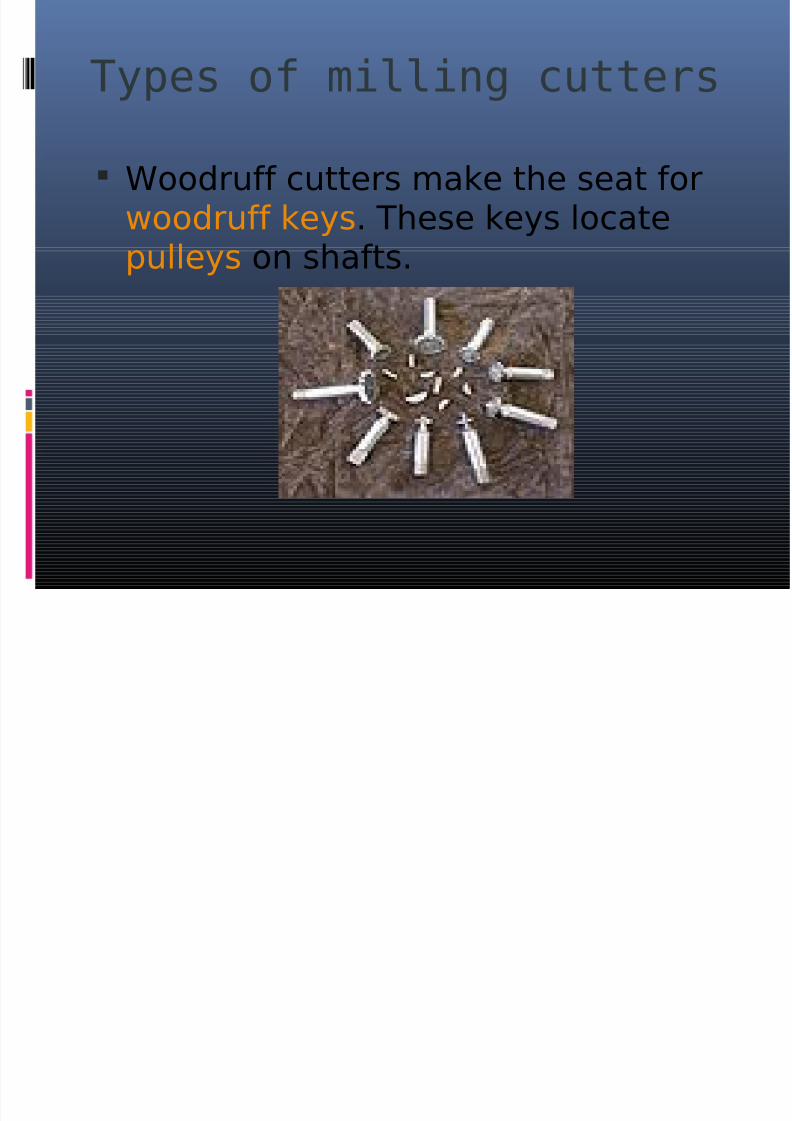
Woodruff cutters make the seat forwoodruff keys. These keys locatepulleys on shafts.

8/9/2019 32199033 Production Engineering Module 2
http://slidepdf.com/reader/full/32199033-production-engineering-module-2 37/60
Types of milling cutters
Hollow mill
Hollow milling cutters, more often calledsimply hollow mills, are essentially
"inside-out endmills". They are shapedlike a piece of pipe (but with thickerwalls), with their cutting edges on theinside surface. They are used onturret lathes and screw machines as analternative to turning with a box tool, oron milling machines or drill presses tofinish a cylindrical boss (such as atrunnion).

8/9/2019 32199033 Production Engineering Module 2
http://slidepdf.com/reader/full/32199033-production-engineering-module-2 38/60

8/9/2019 32199033 Production Engineering Module 2
http://slidepdf.com/reader/full/32199033-production-engineering-module-2 39/60
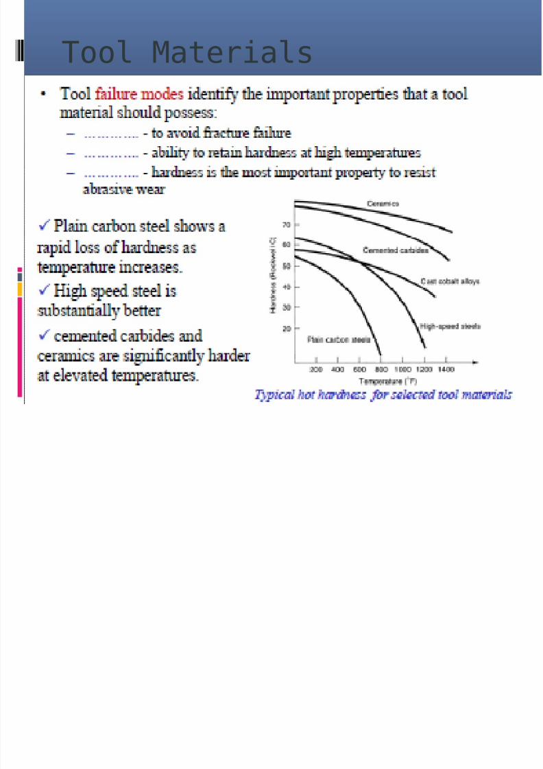
Tool Materials
Steels
Originally, all tool bits were made of high carbon tool steelswith the appropriate hardening and tempering. Since theintroductions of high-speed steel (HSS) (early years of the 20thcentury), sintered carbide (1930s), ceramic and diamondcutters, those materials have gradually replaced the earlier
kinds of tool steel in almost all cutting applications. Most toolbits today are either HSS or carbide.
Carbides and ceramics
Carbide, ceramics (such as cubic boron nitride) and diamond,having higher hardness than HSS, all allow faster materialremoval than HSS in most cases. Because these materials aremore expensive and brittler than steel, typically the body of the cutting tool is made of steel, and a small cutting edgemade of the harder material is attached. The cutting edge isusually either screwed on (in this case it is called an insert), orbrazed on to a steel shank (this is usually only done forcarbide).
8/9/2019 32199033 Production Engineering Module 2
http://slidepdf.com/reader/full/32199033-production-engineering-module-2 40/60
Tool Materials
8/9/2019 32199033 Production Engineering Module 2
http://slidepdf.com/reader/full/32199033-production-engineering-module-2 41/60
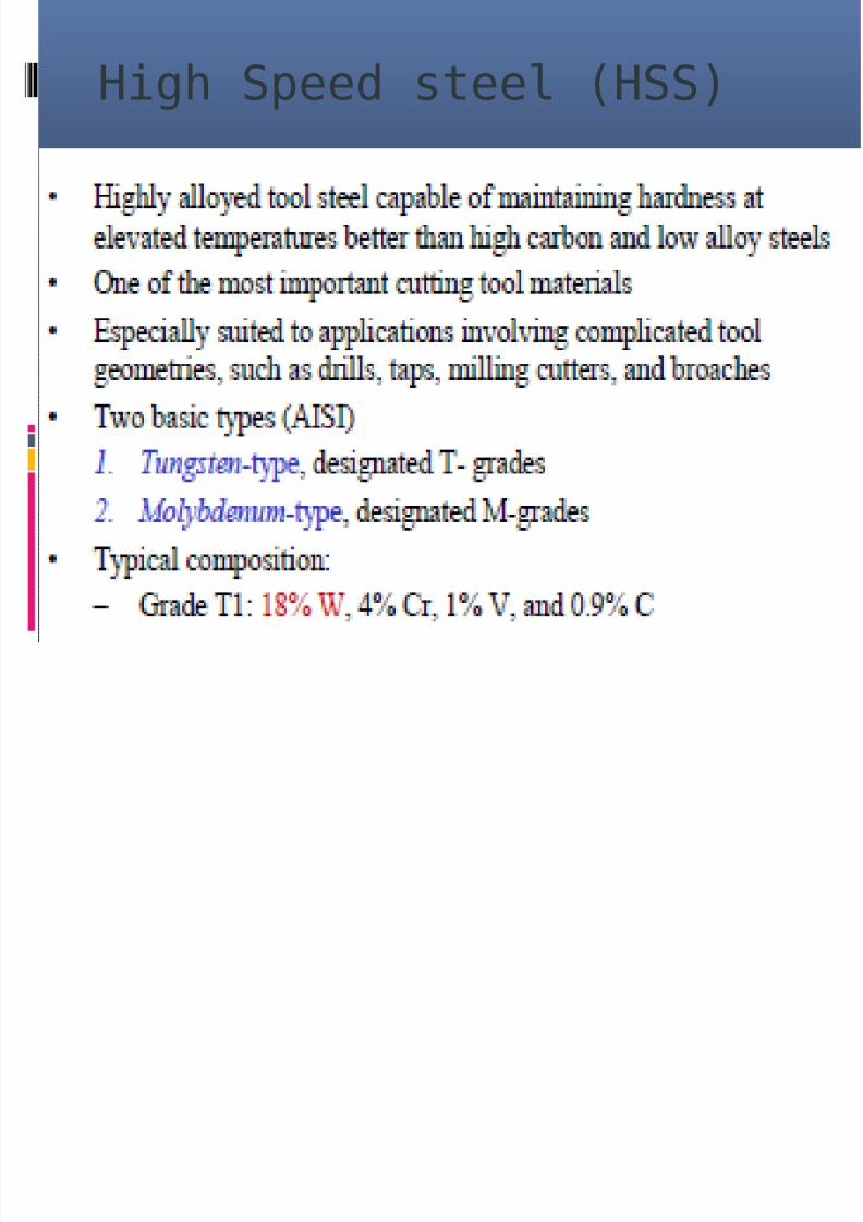
High Speed steel (HSS)

8/9/2019 32199033 Production Engineering Module 2
http://slidepdf.com/reader/full/32199033-production-engineering-module-2 42/60
Cemented Carbides

8/9/2019 32199033 Production Engineering Module 2
http://slidepdf.com/reader/full/32199033-production-engineering-module-2 43/60

8/9/2019 32199033 Production Engineering Module 2
http://slidepdf.com/reader/full/32199033-production-engineering-module-2 44/60

8/9/2019 32199033 Production Engineering Module 2
http://slidepdf.com/reader/full/32199033-production-engineering-module-2 45/60

8/9/2019 32199033 Production Engineering Module 2
http://slidepdf.com/reader/full/32199033-production-engineering-module-2 46/60
Inserts
Almost all high-performance cutting tools use indexableinserts. There are several reasons for this. First of all, atthe very high cutting speeds and feeds supported bythese materials, the cutting tip can reach temperatureshigh enough to melt the brazing material holding it to
the shank. Economics are also important; inserts aremade symmetrically so that when the first cutting edgeis dull they can be rotated, presenting a fresh cuttingedge. Some inserts are even made so that they can beflipped over, giving as many as 16 cutting edges perinsert. There are many types of inserts: some forroughing, some for finishing. Others are made for
specialized jobs like cutting threads or grooves. Theindustry employs standardized nomenclature todescribe inserts by shape, material, coating material,and size.

8/9/2019 32199033 Production Engineering Module 2
http://slidepdf.com/reader/full/32199033-production-engineering-module-2 47/60
Form tools
A form tool is precision-ground into a pattern thatresembles the part to be formed. The form tool canbe used as a single operation and thereforeeliminate many other operations from the slides(front, rear and/or vertical) and the turret, such as
box tools. A form tool turns one or more diameterswhile feeding into the work. Before the use of formtools, diameters were turned by multiple slide andturret operations, and thus took more work to makethe part. For example, a form tool can turn manydiameters and in addition can also cut off the part
in a single operation and eliminate the need toindex the turret. For single-spindle machines,bypassing the need to index the turret candramatically increase hourly part production rates.

8/9/2019 32199033 Production Engineering Module 2
http://slidepdf.com/reader/full/32199033-production-engineering-module-2 48/60
Form tools
On long-running jobs it is common to use aroughing tool on a different slide or turret stationto remove the bulk of the material to reduce wearon the form tool.
There are different types of form tools. Insert formtools are the most common for short- to medium-range jobs (50 to 20,000 pcs). Circular form toolsare usually for longer jobs, since the tool wear canbe ground off the tool tip many times as the tool isrotated in its holder. There is also a skiving toolthat can be used for light finishing cuts. Form toolscan be made of cobalt steel, carbide, or high-speed steel. Carbide requires additional carebecause it is very brittle and will chip if chatteroccurs

8/9/2019 32199033 Production Engineering Module 2
http://slidepdf.com/reader/full/32199033-production-engineering-module-2 49/60
Form tools
A drawback when using form tools is that the feed into thework is usually slow, 0.0005" to 0.0012" per revolutiondepending on the width of the tool. Wide form tools createmore heat and usually are problematic for chatter. Heatand chatter reduces tool life. Also, form tools wider than2.5 times the smaller diameter of the part being turned
have a greater risk of the part breaking off. [1] Whenturning longer lengths, a support from the turret can beused to increase turning length from 2.5 times to 5 timesthe smallest diameter of the part being turned, and thisalso can help reduce chatter. Despite the drawbacks, theelimination of extra operations often makes using formtools the most efficient option.

8/9/2019 32199033 Production Engineering Module 2
http://slidepdf.com/reader/full/32199033-production-engineering-module-2 50/60
Form tool

8/9/2019 32199033 Production Engineering Module 2
http://slidepdf.com/reader/full/32199033-production-engineering-module-2 51/60
Factors which effect toollife & Tool life
relationship Tool Wear Tool wear describes the gradual failure of cutting
tools due to regular operation. It is a term oftenassociated with tipped tools, tool bits, or drill bitsthat are used with machine tools
Types of wear include: flank wear in which the portion of the tool in
contact with the finished part erodes. Can bedescribed using the Tool Life Expectancy equation.
crater wear in which contact with chips erodes the
rake face. This is somewhat normal for tool wear,and does not seriously degrade the use of a tool untilit becomes serious enough to cause a cutting edgefailure.
8/9/2019 32199033 Production Engineering Module 2
http://slidepdf.com/reader/full/32199033-production-engineering-module-2 52/60
Factors which effect toollife & Tool life
relationship Tool WearCan be caused by spindle speed that is too low or a feed rate that
is too high. In orthogonal cutting this typically occurs where thetool temperature is highest. Crater wear occurs approximatelyat a height equaling the cutting depth of the material. Craterwear depth ~ t0 t0= cutting depth
Built-up Edge in which material being machined builds up onthe cutting edge. Some materials (notably aluminum andcopper) have a tendency to anneal themselves to the cuttingedge of a tool. It occurs most frequently on softer metals, with alower melting point. It can be prevented by increasing cuttingspeeds and using lubricant. When drilling it can be noticed asalternating dark and shiny rings.
Glazing occurs on grinding wheels, and occurs when theexposed abrasive becomes dulled. It is noticeable as a sheenwhile the wheel is in motion.
Edge Wear, in drills, refers to wear to the outer edge of a drillbit around the cutting face caused by excessive cutting speed.It extends down the drill flutes, and requires a large volume of material to be removed from the drill bit before it can becorrected.

8/9/2019 32199033 Production Engineering Module 2
http://slidepdf.com/reader/full/32199033-production-engineering-module-2 53/60
Effects of Tool Wear
Some General effects of tool wearinclude: Increased cutting forces
Increased cutting temperatures Poor surface finish
Decreased accuracy of finished part
Reduction in tool wear can be accomplished
by using lubricants and coolants whilemachining. These reduce friction andtemperature, thus reducing the tool wear.

8/9/2019 32199033 Production Engineering Module 2
http://slidepdf.com/reader/full/32199033-production-engineering-module-2 54/60
Tool Life Expectancy
The Taylor Equation for Tool LifeExpectancy provides a goodapproximation.

8/9/2019 32199033 Production Engineering Module 2
http://slidepdf.com/reader/full/32199033-production-engineering-module-2 55/60
Crater Wear

8/9/2019 32199033 Production Engineering Module 2
http://slidepdf.com/reader/full/32199033-production-engineering-module-2 56/60
Temperature
Considerations At high temperature zones craterwear occurs. The highesttemperature of the tool can exceed
700 °C and occurs at the rake facewhereas the lowest temperature canbe 500 °C or lower depending on
the tool.ram

8/9/2019 32199033 Production Engineering Module 2
http://slidepdf.com/reader/full/32199033-production-engineering-module-2 57/60
Energy Considerations
Energy comes in the form of heat from toolfriction. It is a reasonable assumption that 80%of energy from cutting is carried away in thechip. If not for this the workpiece and the toolwould be much hotter than what is experienced.
The tool and the workpiece each carryapproximately 10% of the energy. The percent of energy carried away in the chip increases as thespeed of the cutting operation increases. Thissomewhat offsets the tool wear from increasedcutting speeds. In fact, if not for the energytaken away in the chip increasing as cuttingspeed is increased; the tool would wear morequickly than is found.

8/9/2019 32199033 Production Engineering Module 2
http://slidepdf.com/reader/full/32199033-production-engineering-module-2 58/60
Temperature gradient of tool, workpiece and chipduring orthogonal cutting. As can easily be seen,heat is removed from the workpiece and the tool
to the chip. Crater wear occurs around the 720degree area of the tool.
Cutting Fluids –

8/9/2019 32199033 Production Engineering Module 2
http://slidepdf.com/reader/full/32199033-production-engineering-module-2 59/60
Cutting Fluids Types & Properties
Cutting Fluids –

8/9/2019 32199033 Production Engineering Module 2
http://slidepdf.com/reader/full/32199033-production-engineering-module-2 60/60
Cutting Fluids Types & Properties