3100 series pos bundle - utc retail
TRANSCRIPT
3100 Series™ is a registered trademark of UTC RETAIL 11692017 Rev A 2009 UTC RETAIL. All rights reserved.
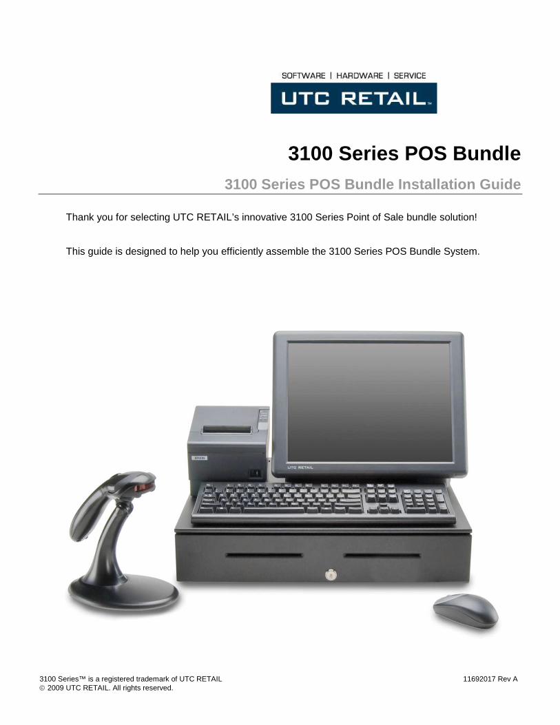
3100 Series POS Bundle 3100 Series POS Bundle Installation Guide
Thank you for selecting UTC RETAIL’s innovative 3100 Series Point of Sale bundle solution!
This guide is designed to help you efficiently assemble the 3100 Series POS Bundle System.
11692017 Rev A - 2 - © 2009 UTC RETAIL
3100 Series POS Bundle System Installation Guide
This guide was prepared by UTC RETAIL to assist personnel with the installation of the bundle components. All attempts have been made to ensure that the information presented in this manual is correct. No liability, expressed or implied, will be assumed by UTC RETAIL or affiliates for damage resulting from the use of this information.
All rights reserved. No part of this document may be reproduced, stored in a retrieval system, or transmitted in any form or by any means, electronic or mechanical, including photocopying, recording, or otherwise, without the prior written permission of UTC RETAIL.
If a unit needs to be shipped to UTC RETAIL for repairs, please return it in the original packaging material and shipping container. If you have questions, please call UTC RETAIL’s Technical Support at 1.800.349.0546.
The 3100 Series Touch Screen POS Workstation complies with UL60950 requirements. This equipment has been tested and found to comply with the limits for a Class “A” digital device, pursuant to Part 15 of the FCC Rules. These limits are designed to provide reasonable protection against harmful interference when the equipment is operated in a commercial environment. This equipment generates, uses, and can radiate radio frequency energy and, if not installed and used in accordance with the instruction manual, may cause harmful interference to radio communications. Operation of this equipment in a residential area is likely to cause harmful interference, in which case the user will be required to correct the interference at his/her own expense.
Safety Precautions DANGER: High Voltage
This unit contains high voltage. There is a risk of electrical shock if the case is opened. If service is required, contact an authorized service agent or UTC RETAIL (UTC).
WARNING: CMOS Battery Damage
Replace your system's battery only with CR-2032 (or equivalent) 3V Lithium-Ion coin cell battery to avoid risk of personal injury or physical damage to your equipment. Always dispose of used batteries according to local ordinance, where applicable. Any damage due to not following this warning will void your motherboard's manufacturer warranty.
WARNING: Access to Internal Components
All access to internal components of the 3100 Series unit is restricted to Authorized Service Personnel only. Opening the case or service by anyone else will automatically void the warranty on this product.
WARNING: Connect AC Power Cable last
To avoid accidental power-up during installation, connect the AC Power Cable last.
WARNING: Electrical Shock
Use caution when connecting cables. To avoid electric shock, do not connect safety extra-low voltage (SELV) circuits to telephone-network voltage (TNV) circuits. Local Area Network (LAN) ports contain SELV circuits, and telephone ports contain TNV circuits. Some LAN ports and some telephone ports use RJ-45 connectors.
CAUTION:
Damage to the unit components may occur if AC power is not removed from the product prior to attaching any accessories.
CAUTION:
Do not hot plug to the rear panel serial ports. Turn off the 3100 Series Unit before connecting serial port cables.
CAUTION:
Do not use the Magnetic Stripe Reader (MSR) unit as a handle when moving or carrying the 3100 Series.

© 2009 UTC RETAIL 3 11692017 Rev A
TABLE OF CONTENTS
3100 SERIES POS BUNDLE SYSTEM INSTALLATION GUIDE ............................................................................................. 2
SAFETY PRECAUTIONS ..................................................................................................................................................................... 2
PRODUCT INFORMATION ........................................................................................................................................................... 4
UN-BOXING THE SYSTEM............................................................................................................................................................ 5
INSTALLATION............................................................................................................................................................................... 5
POWERING ON YOUR 3100 SERIES POS BUNDLE SYSTEM.............................................................................................. 17
TROUBLESHOOTING PROCEDURES ...................................................................................................................................... 18

11692017 Rev A - 4 - © 2009 UTC RETAIL
Product Information
You will find the following components inside the 3100 Series POS Bundle System Box:
• Safety Sheet
• 3100 Series POS All-in-One unit (Touch Screen PC / logic device)
• A/C power cord for logic device
• Cash drawer
• Barcode scanner
• POS receipt printer
• Keyboard
• Mouse
Note: The following optional items may or may not be present depending on the configuration purchased and may be shipped in a separate box.
• Magnetic Stripe Reader (MSR)
• Payment Terminal - Pin Pad device, power supply & cables
• Payment Terminal - Signature Capture device, power supply & cables
• Rear Customer Display
• Inventory Scanner
• AC Power Conditioner
• Traffic Counter and Door Sensor
• Label / Ticket Printer

© 2009 UTC RETAIL 5 11692017 Rev A
Un-boxing the System
1. Open the point-of-sale box and remove the contents.
2. Remove all packing materials.
Installation
1. Orient the cash drawer on its back side on your cash wrap (counter). Remove the keys. Locate the cash drawer cable package, labeled ‘APG cash drawer 320 Multipro cable kit’. Connect the end with the larger modular plug into the jack on the base of the cash drawer.
Figure 1: Bottom View of Drawer
2. Lay down the cash drawer and place the cable to the side.
3. Connect the other end of the cash drawer cable to the POS printer drawer port, labeled ‘DK’.
Figure 2: Bottom View of Drawer
Note: the actual loc ation of the jack on the cash drawer base will vary from drawer model to model.

11692017 Rev A - 6 - © 2009 UTC RETAIL
4. Connect the printer USB cable from the printer to any USB port on the rear of the 3100 Series.
5. Connect the power cable from the printer power supply to the connector on the printer. Connect the AC cable to the printer power supply and then to a wall outlet or the optional Power Conditioner. Optionally, connect cable 11029567 between the printer and the 24VDC output on the 3100 Series.
Figure 3: Rear View of 3100 Series and Printer
6. Connect the mouse and keyboard cables to the 3100 Series. The mouse may be plugged into any USB port and the keyboard port is purple.
Figure 4: Rear View of 3100 Series and Top views of keyboard and mouse
You may eliminate the printer’s AC adapter by connecting cable 11029567 between the 3100 Series 24VDC output and the printer.

© 2009 UTC RETAIL 7 11692017 Rev A
7. Connect the USB connector end of the Barcode Scanner cable to a USB port on the back of the
3100 Series. Connect the other end into the jack on the barcode scanner handle.
Figure 5: Rear View of 3100 Series, Scanner connection
8. Connect the optional MSR (Magnetic Stripe Reader) assembly to the 3100 Series unit as follows:
Figure 6: Side View of 3100 Series and MSR Assembly
1. Remove the connector cover plate
Lay the 3100 Series LCD bezel face down on a clean, smooth surface, ensuring you do not scratch the bezel or LCD panel. On the rear, left side of the LCD display, remove the mounting screws (2) holding the plastic cover. See picture right. Remove the plastic cover and you will observe 3 screw holes.
2. Attach the connector
Lay the MSR, with its molded Swipe icon face down, on the table top next to the 3100 Series workstation. Using a screw from the step above, attach the single black ground wire to the middle screw hole. Orient the metal screw terminal on this ground wire so it is inline with the 3 screw holes. The screw terminal cannot be left hanging over the edge of the MSR mounting location. The cable bundle with the white plug is the data cable. Holding the white plug so the black wire is to your left and the red wires to the right, plug the data cable into the data jack – see the photo on the right.
Ground wire screw
Black wire
Data cable plug and jack
Mounting screws

11692017 Rev A - 8 - © 2009 UTC RETAIL
3. Position the MSR
Align the top and bottom grooves in the MSR unit with the guide rails on the LCD bezel and slide it into position, making sure the ground wire and data cable assembly are not pinched against the bezel wall.
4. Insert and tighten screws
Insert the two screws provided with the MSR unit, and tighten to secure the MSR housing to the main unit. Do not use the MSR as a carrying handle when you move the 3100 Series.
9. Connect the optional Payment Terminal (Pin Pad or Signature Capture device) to an unpowered Serial Port on the back of the 3100 Series. For instructions on the Signature Capture device cable connections, refer to the install guide included with the terminal. Plug the AC power adapter into a wall outlet or the optional Power Conditioner.
Figure 7: Rear View of 3100 Series, Payment Terminal connection
Mounting screws
Groove – top & bottom
Rail – top and bottom

© 2009 UTC RETAIL 9 11692017 Rev A
10. Connect the optional Rear Customer Display as follows:
Figure 8: Side View of 3100 Series Unit
1. Remove the rear cover
On both sides of the rear cover, remove the rubber plugs and the screws behind the plugs. From the rear of the machine, press in the tab on both sides of rear cover, unlocking the rear cover from the front panel. Pull the rear cover straight back, then lift it off the machine.
Press tab here (both sides of cover)

11692017 Rev A - 10 - © 2009 UTC RETAIL
2. Remove the knockout Being careful not to scratch the cover, turn it over and hold it in your lap. Locate the plastic knockout and its tabs on the back side of the cover. Ensuring the knockout is not against your leg, and using a flat instrument, apply a slow, steady pressure on the knockout’s retaining tabs, while pushing down on the knockout with your thumb. The knockout will slowly start to release, and then pop out.
3. Snap the pole adapter into place
From the 3100 Series RCD box, remove the pole adapter. Turn the rear cover over (right side up) and align the 4 tabs on the pole adapter with the 4 slots in the rear cover. The adapter will only attach in one way; the smallest pole adapter tab goes towards the rear of the rear cover. Press the pole adapter into the cover's knockout hole until the adapter locks into place.
4. Configuring the COM Ports
The 3100 Series has 4 serial ports; one of these ports will be used to send power and data to the 3100 Series RCD. Check with your POS software supplier for information regarding which serial port you should use. Serial ports are also known as COM ports; the remainder of this manual will assume COM2 is the port being used. The 3100 Series RCD requires +5VDC on pin 9 of the DB9 serial cable and the 3100 Series standard configuration has COM2, COM3 and COM4 ports setup to provide +5VDC to pin 9. If you have not modified this standard configuration, continue the installation at Step 8, “Attaching the RCD Head” section of this document.
5. Open the chassis
Set the rear cover aside. Gently pull straight back (a half inch) on the handle on the rear of top cover of the logic unit chassis. The cover will unlock from the chassis bottom.

© 2009 UTC RETAIL 11 11692017 Rev A
6. Raise the cover
Pivot the cover up; unplug the power connector (circled in red in the photo to the right) by pressing its tab and pulling it out of the motherboard jack. Raise the cover fully; aligning the pivot screws in the chassis slots and locking the rear cover up at a 45° angle.
7. Configure the COM port to provide +5VDC to Pin 9
Use the drawing below to locate the terminal block you need. COM1→JP4, COM2→JP5, COM3→JP7, COM4→JP6. The drawing’s left side is the rear of the motherboard; pin 1 on each terminal block is indicated by the small black circle. When pins 7 and 8 are jumpered, pin 9 of the serial port is signal RI for a modem. When pins 9 and 10 are jumpered, +5VDC is routed to pin 9 of the serial port. Remove the jumper connecting pins 7 and 8 and install it to connect pins 9 and 10. On a 3100 Series in its standard configuration, JP4 has a jumper connecting pins 7 and 8, whereas on JP5, JP7 and JP6 that jumper has been moved to connect pins 9 and 10.
Reverse previous steps to close the cover. Lift the chassis cover out of the locking slots, reconnect the power cable, lay the cover flat on the main chassis and slide it forward the half inch required to seat the pivot barrels into their mating slots.

11692017 Rev A - 12 - © 2009 UTC RETAIL
8. Attaching the RCD Head
Install the rear cover back onto the 3100 Series. Do not install the rear cover screws and plugs at this time. Remove the RCD head from the box and feed the RCD head's cable through installed adapter and behind the handle on the chassis cover. Continue to install the head onto the adapter, locking the adapter’s nub into the middle of the 5 holes in the RCD pole adapter.
9. Connect to the COM Port
Lift up the rear door of 3100 Series. Obtain the cable with the 9-pin serial plug from the RCD product box; plug it into the COM port matching the port selected in the “Configuring the COM Ports” section. The photo to the right shows the cable attached to the COM2 jack. Secure the plug to the chassis using the two attached locking screws. Connect the other end of this cable with the cable from the RCD head; align the two plugs, press and lock them together.
10. Testing the RCD
Finish configuring your 3100 Series POS Bundle (Steps 11-13 on the following pages), then return here to test the RCD.
Turn on the 3100 Series. A bootup message (shown at right) will appear on the RCD for about 2 seconds.
When at the Windows desktop, start HyperTerminal. Look on the Start menu, All Programs→Accessories→ Communications→HyperTerminal
If necessary, answer the question regarding default telnet program.

© 2009 UTC RETAIL 13 11692017 Rev A
If necessary, put in your local area code.
Accept the Phone and Modem Option presented, or edit it as desired.
Enter a Connection Description.

11692017 Rev A - 14 - © 2009 UTC RETAIL
Select the COM port to which you connected the RCD.
Click the Configure button that appears and setup the COM Properties form that appears as seen on the right.
When you click OK, the form will disappear and the software will connect to the RCD. Click the Disconnect icon.

© 2009 UTC RETAIL 15 11692017 Rev A
Click the Properties icon. Click the Settings tab and then the ASCII Setup... button. Check the “Echo typed characters locally” box and the “Send line ends with line feeds” box.
On the main page, click on the Call icon.
Now type a test message using a POS keyboard. Your message will appear in the HyperTerminal window and on the RCD. The RCD can display 2 lines of 20 characters each. The display will wrap to line 2 after the 20th character. At the 20th character on line 2, line 2 will move to line 1 position. The Esc key will erase the display and return to line 1, character 1 position.
The message will be displayed in the RCD.
To detach HyperTerminal from the RCD, click the Disconnect icon and then exit HyperTerminal. Any message in the RCD will remain until the 3100 Series is restarted.
Install the Rear Cover’s screws and rubber plugs.
RS232 RCD Factory Settings Baud -rate = 9600, Word length = 8, Stop bits = 2, Parity = None. Refer to the 3100 Series RCD Programming guide to change baud rates or parity.

11692017 Rev A - 16 - © 2009 UTC RETAIL
11. Connect the optional Inventory Scanner to a serial port on the back of the 3100 Series. If you are using the scanner’s power supply, disable the serial port power as described above. Then plug the power supply into a wall outlet or the optional Power Conditioner.
Figure 9: Rear View of 3100 Series Inventory Scanner connection
12. Connect a site provided network cable into the network jack on the back of the 3100 Series.
Figure 10: Rear View of 3100 Series , Network cable connection
© 2009 UTC RETAIL 17 11692017 Rev A
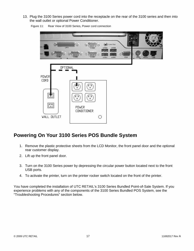
13. Plug the 3100 Series power cord into the receptacle on the rear of the 3100 series and then into the wall outlet or optional Power Conditioner.
Figure 11: Rear View of 3100 Series, Power cord connection
Powering On Your 3100 Series POS Bundle System
1. Remove the plastic protective sheets from the LCD Monitor, the front panel door and the optional rear customer display.
2. Lift up the front panel door.
3. Turn on the 3100 Series power by depressing the circular power button located next to the front USB ports.
4. To activate the printer, turn on the printer rocker switch located on the front of the printer.
You have completed the installation of UTC RETAIL’s 3100 Series Bundled Point-of-Sale System. If you experience problems with any of the components of the 3100 Series Bundled POS System, see the “Troubleshooting Procedures” section below.

11692017 Rev A - 18 - © 2009 UTC RETAIL
Troubleshooting Procedures
The following table presents symptoms and solutions for problems potentially encountered when installing the 3100 Series Bundled POS System components.
Symptom Solutions
Touch screen accuracy is off
• Recalibrate the touch screen using the calibration utility located in the Control Panel using the Elo Touchscreen application and click on the Align button.
The printer does not have power.
• Check to see if the printer power cable is properly connected to the printer.
• Make sure that the printer power switch is ON.
The printer has power but the system does not boot to Windows.
• Push the power button in the front of the logic unit located under the front panel door.
A keyboard error message displays when you boot the 3100 Series POS unit.
• Check to see if the keyboard cable is properly connected to the keyboard and the rear panel of the 3100 Series.
The rear customer display does not have power.
• Make sure the customer display is plugged in to connector provided on back of unit behind the panel cover.
Please call UTC RETAIL’s Technical Support at 800.349.0546, if you have any problems not addressed in the Troubleshooting Procedures or have questions about other sections of this documentation.