cis 3100.pdf
TRANSCRIPT

PHONTECH
PHONTECH COMMUNICATION P.B. 274, 3183 HORTEN NORWAY
PHONE +47 33 08 35 00 FAX +47 33 08 35 01 E-mail : [email protected]
www.phontech.no
DOCUMENTATION HANDBOOK
COMMAND INTERCOM SYSTEM – CIS 3100
1
2
3
4
5
CALL
ALLTALK
CIS 3100
VOLUME

VALGMULIGHETER PÅ CIS 3100, 3101 OG 3102SELECTIONS ON THE CIS 3100, 3101 AND 3102
CIS 3100: S.NO.:
CIS 3101: PROG. VER.:
CIS 3102:
CIS 3100, 3101 og 3102 har noen enkle valgmuligheter for drift og tilkobling. Valgmulighetene finnes i form av "strap'er"(koblingslinker). Strap'ene kan enten være åpne eller lukkes med egnede linker (blå). Strap'ene har følgende funksjon:
The CIS 3100, 3101 and 3102 contains some selections regarding operation and connections. These selections are madeby opening or closing straps. The straps have the following functionality:
Strap TilstandCondition
Beskrivelse / FunksjonDescription / Functionality
Status: Stan-dard
ST1 lukketST2 åpen
ST1 closedST2 open
Benytter tilleggsmikrofon, integrert mikrofon nyttes ikke
Using an additional microphone, the integrated microphone is not used
ST1 åpenST2 lukket
ST1 openST2 closed
Benytter integrert mikrofon, tilleggsmikrofon på enheten er ikke montert
Using the integrated microphone, an additional unit microphone is not mounted ü
ST3 åpenST3 open
Styrbord broving interface benyttes som broving - NORMALStarboard bridge wing interface is used as bridge wing interface - NORMAL ü
ST3 lukket
ST3 closed
Styrbord broving interface benyttes som inngang for eksternt PRIORITERTALLE KALLStarboard bridge wing interface is used as input for external PRIORITY ALLCALL
ST4 åpenST4 open
Mikrokontroller RESET: Skal alltid være åpen i normal driftMicrocontroller RESET: Always open during normal working conditions ü ü
ST4 lukketST4 closed
Benyttes kun av service personell: Skal alltid være åpen i normal driftOnly to be used by service personell: Always open during normal workingconditions
ST5 åpen
ST5 open
Frakoble høyttaler audio til styrbord broving interface. Benyttes ved tilkobling tileksternt nøklingsutstyr f.eks. PA-system, PABX etc.Disable loudspeaker audio to the starboard bridge wing interface. This facility isused in line feed conditions. i.e PA-system, PABX etc.
ST5 lukket
ST5 closed
Tilkoble høyttaler audio til styrbord broving. Benyttes ved NORMAL brovingfunksjonEnable loudspeaker audio to the starboard bridge wing. This facility is used inNORMAL bridge wing operation
ü
ST6 lukket-ST7 åpen
ST6 closed-ST7 open
Styrbord broving er tilkoblet linje nivå (0dBm) interface. F.eks. PA system,PABX etc.The starboard bridge wing is connected to a line level (0dBm) interface, i.e. PAsystem, PABX etc.
ST6 åpen-ST7 lukket
ST6 open-ST7 closed
Styrbord broving er tilkoblet mikrofon nivå interface, f.eks. broving mikrofon,mikrofon for PRIORITERT ALLE KALLThe starboard bridge wing is connected to a microphone level interface, i.e.bridge wing microphone, microphone for PRIORITY ALL CALL
ü
STRAPB_1.SAM
Page 1 of 1
ST2 ST1
ST2 ST1
ST3
ST3
ST4
ST4
ST5
ST5
ST7 ST6
ST7 ST6

DECLARATION OF CONFORMITY (Manufacturers Declaration)
COMMAND INTERCOM SYSTEM CIS 3000
The CIS 3000 has been tested and found to comply with the following standard:
• Maritime navigation and radio communication equipment and systems – General requirements – Methods of testing and required test results IEC 60945 (1996, third edition).
o Ch. 9: Unwanted electromagnetic emission – Methods of testing and required test results.
o Ch.10: Immunity to electromagnetic environment - Methods of testing and required test results.
• IMO Resolution A.813: General requirements for electromagnetic
compatibility (EMC) for all electrical and electronic ships equipment. Ref. DNV test report no. 2002-3157 and project no. 420 10346. Manufacturer: Phontech A/S Bromsveien 19 3192 Horten NORWAY Horten, Norway 22.05.2002 on behalf of Phontech A/S
_____________________ Thor Bertrand Andersen QA Manager
Doc.No.: 97301-000-DE
Page 1 of 16
4 2003.09.04 REVISION, EM 964 ASk TBA ASk 3 010424 REVISION, EM 846 ASk TBA ASk 2 980209 REVISION, EM 680 ASk t.ly ASk 1 980109 REVISION, EM 677 ASk t.ly ASk 0 970401 DEVELOPMENT t.ly ASk t.ly
REV No: ISSUE DATE REASON FOR ISSUE PREPARED CHECKED APPROVED
This document is the property of PHONTECH and must not be copied or shown to a third person without our written acceptance. In the interest of product improvement, PHONTECH reserves the right to alter specification and design without notice.
SIZE: NA UED no: 94
DOC no: 97301-000-DE
TITLE: CIS SYSTEMS MASTER STATION SERIES 310X Description / Beskrivelse
FILE NAME: 97301-000-DE.doc
1712
11 16
VOLUME
CIS 3102
CALL
1813
1914
15 20 ALLTALK
72
1 6
83
94
5 10
7
6
VOLUME
8
9 CALL
CIS 3101
10ALL
TALK
2
1
3
4
5
2
1
VOLUME
3
4 CALL
CIS 3100
5ALL
TALK

Doc.No.: 97301-000-DE
Page 2 of 16
PHONTECH
CONTENTS.
1.0 INTRODUCTION / INTRODUKSJON
2.0 GENERAL DESCRIPTION / GENERELL BESKRIVELSE
3.0 FACILITY LIST / FUNKSJONER OG MULIGHETER
4.0 MOUNTING / INSTALLATION / SCREEN CONNECTION. MONTERING / INSTALLASJON OG SKJERM TERMINERING
5.0 CABLE REQUIREMENTS / KRAV TIL KABEL
6.0 SELECTIVE CALLS / SELEKTIVE ANROP
7.0 ALL CALL / ALLEKALL(FELLESANROP)
8.0 BRIDGE WING - EXTERNAL PAGING BROVING - EKSTERNT AKTIVERT ANROP
9.0 PRIORITY / PRIORITET
10.0 CALLS DURING AN EXTERNAL ALL-CALL ANROP UNDER EKSTERNT ALLEKALL
11.0 INTENTIONALLY LEFT OUT / UTELATT
12.0 INTENTIONALLY LEFT OUT / UTELATT
13.0 TECHNICAL DATA / TEKNISKE DATA
14.0 SYSTEM BOARD 97301-001 (CIS 3100/3101) STRAPPING AND CONNECTION POINT LOCATIONS. LOKALISERING AV LINKER OG KONTAKTPUNKTER
15.0 SYSTEM BOARD 97301-011 (CIS 3102)
STRAPPING AND CONNECTION POINTS LOCATION. LOKALISERING AV LINKER OG KONTAKTPUNKTER

Doc.No.: 97301-000-DE
Page 3 of 16
PHONTECH
1.0 INTRODUCTION / INTRODUKSJON Eng.:
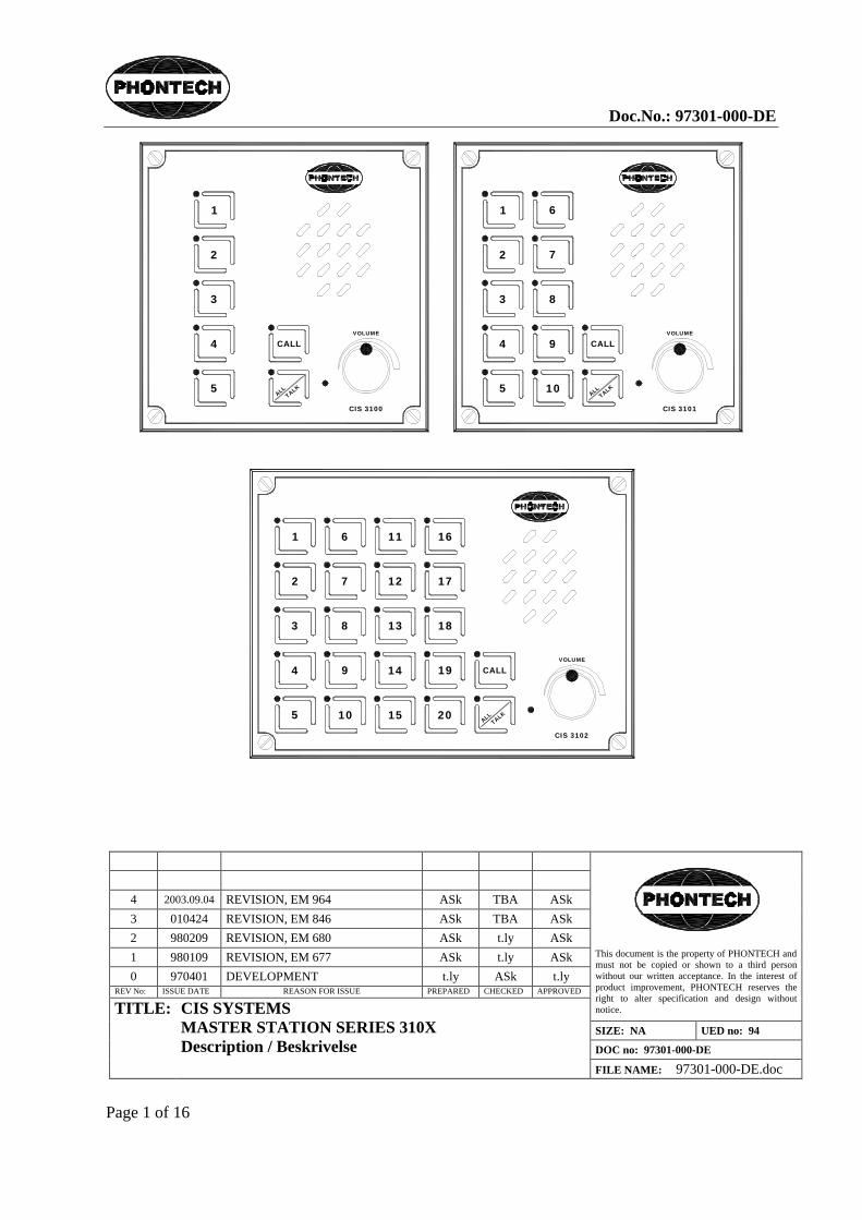
A command intercom system (CIS) consist of one MASTER station (3100 series), most often located on the ships bridge, and distributed SUBSTATIONS (9000 series) in cabins, engine room, engine control room a.s.o. The CIS may also comprise port and starboard side BRIDGE WING stations. The CIS may also be interconnected with the PHONTECH small public address and alarm system (SPA). The CIS serves as two-way command and intercom system. The communication channels is to/from the master station and the substations. Please note that communication between the substations is not possible. The compact design makes the CIS easy to install. The mounting is for 3100/3101 DIN 144 x 144mm, 3102 DIN 192 x 144 mm. flush mounting, or wall mounting. (wallmount backbox required)
No.:
Et kommando intercom system (CIS) består av en MASTER stasjon (3100 serie), som oftest plassert på båtens bro, og distribuerte understasjoner (9000 serie) i lugarer, motorrom, motor kontrollrom osv. CIS kan også omfatte babord og styrbord broving stasjoner. Systemet kan også tilkobles til PHONTECH "small public address and alarm system" (SPA). CIS tjener som et to-veis kommando kommunikasjonssystem, med oppkallsmulighet begge veier. Kommunikasjonen går mellom master og understasjoner, dvs. at kommunikasjon mellom understasjoner ikke er mulig. Det kompakte designet gjør systemet lett å installere. Montering er for 3100/3101 DIN 144 x 144mm, 3102 DIN 192 x 144 mm. innfelt montering eller på vegg montasje. ting. Veggmontering krever ekstra bakboks som er ekstrautstyr.
2.0 GENERAL DESCRIPTION / GENERELL BESKRIVELSE Eng.:
The CIS is delivered as follows:
MASTER STATIONS - 3100 CIS MASTER STATION max. 5 extensions. Amplifier capacity 10W. - 3101 CIS MASTER STATION max. 10 extensions. Amplifier capacity 20W. - 3102 CIS MASTER STATION max. 20 extensions. Amplifier capacity 40W.
SUBSTATIONS, ACCESSORIES - 9001 substation for cabins and/or accommodation areas. - 9003 substation for headset with relay. - 9004 call unit for loudspeaker, weatherproof. - 9009 call unit for portable loudspeaker, weatherproof. - 9011 plug box, weatherproof. - 9016 call unit for loudspeaker, loudspeaker on/off switch, weatherproof.
- 0035 engine control room phone. (handset) - 0005 headset 10 m. cable and plug. - 0006 additional handset. - 0010 portable loudspeaker cable and plug. - 0012 gooseneck microphone unit, PTT, flush mounting. - 0013 microphone box, bridge wing connection. - 0017 hand microphone cable and plug. - 0019 line amplifier. The MASTER stations contains the electronics required in an CIS. As an extended value added feature, the CIS 310X units are supplied with a "loudspeaker as substation / automatic call disable" facility. This makes the installer able to connect plain loudspeakers directly as substations. During power on the CIS 310X unit will detect such configurations and prevent calls from this positions.
No.:
CIS leveres som følger:

Doc.No.: 97301-000-DE
Page 4 of 16
PHONTECH
MASTER STASJONER: - 3100 CIS MASTER STASJON maks. 5 linjer. Forsterker kapasitet 10 W. - 3101 CIS MASTER STASJON. maks. 10 linjer. Forsterker kapasitet 20 W. - 3102 CIS MASTER STASJON. maks. 20 linjer. Forsterker kapasitet 40 W.
UNDERSTASJONER/UTSTYR: - 9001 understasjon for lugar/ oppholdsrom. - 9003 understasjon for hodesett med rele. - 9004 oppkallsenhet for høyttaler, værsikker. - 9009 kalleenhet for bærbar høyttaler, værsikker. - 9011 plugg boks værsikker. - 9016 kalleenhet for høyttaler, høyttaler bryter, værsikker.
- 0035 maskinkontroll rom telefon. (håndsett) - 0005 hodesett med 10m kabel og plugg. - 0006 ekstra handsett. - 0010 bærbar høyttaler,med kabel og plugg. - 0012 svanehals mikrofon enhet, tal knapp, innfelt montering. - 0013 mikrofonboks for broving tilkobling. - 0017 håndmikrofon med kabel og plugg. - 0019 linjeforsterker. MASTER stasjonene inneholder stort sett all elektronikken som kreves i et CIS system. I tillegg er alle CIS 310X enheter utstyrt med funksjonen "høyttaler som understasjon / automatisk oppkalls-hindring. Dette gir installatøren mulighet til å tilkoble høyttalere direkte til understasjon linjer. Ved påslag vil CIS 310X enheten oppdage dette og i ettertiden hindre oppkall fra disse posisjonene.
3.0 FACILITY LIST Eng.:
(see figure 1)
CIS 3100: - Connection for 5 substation lines.
CIS 3101: - Connection for 10 substation lines.
CIS 3102: - Connection for 20 substation lines.
COMMON: - Loudspeaker as substation / automatic call disable - Connection for port and starboard bridge wing stations. - Connection for phonTECH SPA system. - Built-in wide-band loudspeaker. - Built- in condenser microphone. - Automatic gain control for speech level. - Loudspeaker volume control - Bi-coloured key indicator leds. - Call key. - Talk key. - Automatic all call function. - Extra signal organ output for line 1-4. - External loudspeaker output connections.

Doc.No.: 97301-000-DE
Page 5 of 16
PHONTECH
OPTIONS. - Line engagement time out. - Optional extra signal organ output for all lines (up to 10) - Optional line amplifier connection. - Gooseneck/handheld microphone connection.
No.:
CIS 3100: - Tilkobling for 5 understasjoner.
CIS 3101: - Tilkobling for 10 understasjoner.
CIS 3102: - Tilkobling for 20 understasjoner.
FELLES: - Høyttaler som biapparat / automatisk oppkalls-hindring - Tilkobling for babord og styrbord broving stasjoner. - Tilpasset for sammenkobling med phonTECH SPA system. - Innebygget bredbånds høyttaler. - Innebygget kondensator mikrofon. - Automatisk nivå kontroll krets for tale. - Høyttaler volum kontroll. - To-fargede linje indikasjons lysdioder. - Kalle tast. - Tale tast. - Automatisk allekall funksjon. - Ekstra signal giver utgang for linje 1-4. - Ekstern høyttaler utgang. VALGBART: - Automatisk tidsstyrt linje nedkobling - Ekstra signal utgang for alle linjer. (opp til 10) - Linje forsterker tilkobling. - Svanehals /håndmikrofon tilkobling

Doc.No.: 97301-000-DE
Page 6 of 16
PHONTECH
FIGURE 1 / FIGUR 1
2
1
VOLUME
3
4 CALL
CIS 3100
5ALL
TALK
4.0 MOUNTING / INSTALLATION / SCREEN CONNECTION MONTERING / INSTALLASJON OG SKJERMTERMINERING
Eng.: MOUNTING: The master stations 3100/3101/3102 is delivered for flush mounting. On request the units may be delivered with wall-mounting box. (option)
Front plate dimensions 3100 and 3101: 144 x 144 mm. (HxW) 3102: 144 x 192 mm. (HxW) Cut- out dimensions for flush-mounting 3100 and 3101: 115 x 115 mm. (HxW) 3102: 115 x 163 mm. (HxW) Depth, all types flush mounted: 100 mm. wall mounted: 100 mm.
INSTALLATION: The installation should be planned in details before starting. The cables should be listed in a cable plan, with number of pairs a.s.o. The location of each unit in the intercom system should be planned to obtain maximum performance and user ability. The master station location/ orientation with regards to the operator must be taken especially into consideration. Please note the gooseneck mic (if installed) is "close talk". A close talk microphone has the ability to reduce surrounding noise to a minimum. The drawback is that the operator has to speak no more than 5-10 cm away from the microphone.
SCREEN CONNECTION. In order to obtain maximum performance after installation, it is necessary to terminate the cables and ground the screens in a good manners. The cables is to be de-isolated by removing approximately 250 mm of the outer insulation. Then the

Doc.No.: 97301-000-DE
Page 7 of 16
PHONTECH
screen braid is cut off appr. 30 mm longer than the outer isolation. The conductors is de-isolated and fitted with end- crimps before they are inserted into the terminal. The outer screen is clamped to the cable fixing arcs inside the cabinet. Cable ties of a conductive type is recommended for best result.
Please see figure 2 for more details.
No.:
Hoved stasjonene 3100/3101/3102 leveres som standard for innfelt montering. På forespørsel kan veggboks leveres for utvendig montering
Front plate dimensjoner 3100 and 3101: 144 x 144 mm. (HxB) 3102: 144 x 192 mm. (HxB) Utstansingsmål for innfelt montering, 3100 and 3101: 115 x 115 mm. (HxB) 3102: 115 x 163 mm. (HxB) Dybde, alle typer innfelt montering: 100 mm. utvendig montering: 100 mm.
INSTALLASJON: Installasjonen bør planlegges i detalj før start. Kablene bør listes i en kabel plan med nummererte par etc. Plasseringen av hver enhet i intercom systemet bør kartlegges for å oppnå maksimal bruksvennlighet og ytelse. Det bør legges spesiell vekt på plassering av hovedstasjon i forhold til operatøren. Viktig å vite er at dersom det installeres en svanehals mikrofon (gooseneck microphone) er denne ofte "close-talk", dvs. med direktiv virkning. En direktiv mikrofon har den fordel at den er lite følsom for omgivelsesstøy. Ulempen er at operatøren må svært nær for å tale (5-10 cm).
SKJERM TERMINERING: For å oppnå maksimal lydkvalitet er det meget viktig med god og riktig terminering av skjerm. Kablene skal avisoleres ved å fjerne den yttre beskyttelses kappen i en lengde på ca 250mm. Deretter kuttes ytterskjermen slik at denne stikker ca. 30 mm ut fra kabelisolasjonen. Lederne avisoleres og helst påmonteres termineringshylser for å oppnå best og varig kontakt i skruterminalene. Ytterskjermen klemmes inntil de dertil egnede feste punktene på innsiden av bakboksen. For å oppnå best kontakt bør festebånd av elektrisk ledende materiale benyttes.
Ref. figur 2 for detaljer

Doc.No.: 97301-000-DE
Page 8 of 16
PHONTECH
FIGURE 2 / FIGUR 2
Eng.: The cable outer screens is to be terminated as shown. Conductive type of cable ties is recommended to obtain best possible screen connections.
No.:
Kabelens ytterskjerm skal termineres som vist. Festebånd av ledende materiale bør benyttes for å oppnå best kontakt mellom skjerm og chassis.
5.0 CABLE REQUIREMENTS / KRAV TIL KABEL
Eng.: To substations: one pair, twisted, outer screen. If extra signal organ: one pair extra. To bridge wings: two pairs, individually twisted, outer screen. Power cables: one pair, gnd. Minimum conductor area all cable types: 0.75 mm2.
IMPORTANT: TO SECURE UN-INTERFERED OPERATION DO NOT COMBINE SIGNAL CABLES WITH OTHER CABLE TYPES SUCH AS MAINS SUPPLY. THE CABLING FOR THE CIS SYSTEM SHOULD BE A SEPARATE NETWORK.

Doc.No.: 97301-000-DE
Page 9 of 16
PHONTECH
Consult drawings 97301-007-EC (CIS 3100), 97301-002-EC (CIS 3101) and 97301-013-EC (CIS 3102) for further cabling information.
No.:
Til understasjoner: ett par revolvert, utvendig skjermet. Ved ekstra signal organ: et ekstra par. Til broving: to par, individuelt revolvert, utvendig skjerm. Kraft kabler: ett par, jord. Minimum tverrsnitt alle typer: 0,75 mm2.
VIKTIG: FOR Å SIKRE UFORSTYRRET DRIFT, IKKE KOMBINER SIGNAL KABLER MED KABLER FOR ANNET UTSTYR SOM F.EKS. NETTKABLER OSV. KABLINGEN FOR CIS SYSTEMET SKAL VÆRE ET EGET NETT.
I dokumentene 97301-007-EC (CIS 3100), 97301-002-EC (CIS 3101) og 97301-013-EC (CIS 3102) finnes ytterligere informasjon.
6.0. SELECTIVE CALLS / SELEKTIVE ANROP Eng.:
This chapter describes the operation of the CIS master stations. In idle status / after power-up, the master station line indicator leds illuminates dim green as night orientation light.
No.: Dette kapittelet beskriver bruken av hovedstasjonene. I hvilestilling og etter påslag lyser hovedstasjonens lysdioder svakt grønt . (bakbelysning)
6.1. MASTER CALL TO A SUBSTATION / HOVEDSTASJON ANROPER UNDERSTASJON Eng.:
- Select the line by operating the appropriate line key. The line indicator led turns red. - Now press the CALL key. This will generate an attention tone in the substation unit loudspeaker and activate the extra signal device if any. Note: several lines may be called simultaneously.
No.: - Velg ønsket linje ved å trykke inn linjeknappen. Linje indikator lysdiode skifter til rødt fullt lys. - Trykk CALL knappen. Dette starter en oppmerksomhetstone i understasjonens høyttaler/ hodesett. Eventuelt ekstra signal organ starter også. NB: flere linjer kan kalles samtidig.
6.2. MASTER CALL TO ALL SUBSTATIONS / HOVEDSTASJON ANROPER ALLE UNDERSTASJONER
Eng.: - Press the ALL/TALK key without any lines engaged. The master station automatically enters the all-call mode. All the leds illuminates red colour. -Speak into the microphone.
No.: - Trykk ALL/TALK knappen uten noen linjer aktive. Hovedstasjonen velger automatisk alle-kall modus. Alle lysdiodene tenner rødt lys, også lysdiode for ALL/TALK knappen. -Snakk direkte inn i mikrofonen.
Doc.No.: 97301-000-DE
Page 10 of 16
PHONTECH
6.3 A SUBSTATION ANSWER THE CALL FROM THE MASTER / UNDERSTASJONEN SVARER PÅ ANROP FRA HOVEDSTASJON
Eng.: When the attention tone is heard in the loudspeaker and / or the extra signal organ is activated: - Press the talk-key and answer the call. - Keep the TALK key pressed all time during the conversation.
No.: Når oppmerksomhetstonen høres i høyttaleren / eller ekstra signal giver aktiveres: - Trykk på TALK knappen for å svare oppkallet. - Hold TALK knappen inne hele tiden mens samtalen pågår.
6.3. THE MASTER TALKING TO THE SUBSTATION / HOVEDSTASJONEN SNAKKER TIL EN UNDERSTASJON
Eng.: When the call is answered: - Operate the TALK key on the master and talk into the microphone / loudspeaker. - Release the talk-key to return to listen-mode.
No.: Når understasjonen svarer oppkallet: - Trykk TALK knappen og snakk inn i mikrofonen / høyttaleren. - Slipp TALK knappen for å returnere til lytte-modus.
6.5. SUBSTATION CALL TO MASTER / UNDERSTASJON OPPKALL TIL HOVEDSTASJON Eng.:
- Press the CALL button on the substation / call unit. This generates an attention tone in the master station as long as the call-button is kept pressed. Simultaneously the appropriate line indicator led turns full light green to indicate which substation made the call. Note: If a call occurs during an on-going conversation, the attention tone is disabled, but the line indicator led change to green colour full intensity.
No.: - Trykk på CALL knappen på understasjonen. Dette starter oppkallstonen i hovedstasjonen, og denne lyder så lenge understasjonen prøver å kalle opp. Samtidig tenner linjens lysdiode grønn, fullt lys, for å indikere hvilken understasjon som kaller. Viktig: hvis et oppkall inntreffer under pågående samtale, aktiveres ikke kalletonen, men lysdioden tenner fullt grønt lys.
6.6. THE MASTER ANSWER THE CALL FROM A SUBSTATION / HOVEDSTASJONEN SVARER PÅ ANROP FRA UNDERSTASJONEN
Eng.: To answer the call from a substation: - Press the appropriate line key. The line indicator led turns green full intensity. - Press the talk key and speak into the microphone. - Release the TALK key to return to listen mode.
No.: For å svare et oppkall fra en understasjon. - Trykk inn gjeldende linjeknapp. Lysdioden tenner fullt rødt lys. - Trykk inn TALK knappen og snakk inn i mikrofonen. - Slipp TALK knappen for å returnere til lytte-modus.

Doc.No.: 97301-000-DE
Page 11 of 16
PHONTECH
6.7. TERMINATING THE CONVERSATION / AVSLUTTE SAMTALEN Eng.:
The conversation is terminated by de-activating the line: - Operate the line key once more. The line indicator led turn green half-light intensity. (backlight)
No.: Samtalen avsluttes ved å legge linjen ut igjen: - Trykk linjeknappen en gang til. Lysdioden skifter til grønt baklys (hvilestilling).
7.0. ALL CALL / ALLEKALL Eng.:
The master station CIS 3100/3101/3102 may perform an ALL CALL to the substations. - Operate the ALL/TALK key. (no lines active) A special attention tone (1kHz chopped) is distributed to all the substations for about 2-3 seconds. Simultaneously all the extra signal organ outputs is activated for 2-3 seconds. All the line indicator leds turns red colour. The call key indicator led illuminate red during this interval (2-3 seconds.) When this led turns off again the system is ready to use. - Give the message and release the ALL/TALK key.
No.:
Hovedstasjonene CIS 3100/3101/3102 kan utføre alle kall til understasjonene. - Trykk inn ALL/TALK knappen når hovedstasjonen er i hvilestilling (ingen linjer aktivert). En spesiell tone 1kHz pulset (viktig melding), distribueres til alle understasjonene i cirka. 2-3 sekunder. Samtidig aktiveres alle ekstra signal utganger i cirka 2-3 sekunder. Alle linje indikator lysdioder tenner rødt. Call knappens lysdiode tenner rødt i 2-3 sekunder. Når CALL knappens lysdiode slukker er systemet klart til bruk. - Snakk inn i mikrofonen og slipp TALK knappen etter meldingen.
8.0 BRIDGE WING - EXTERNAL PAGING / BROVING - EKSTERNT AKTIVERT ANROP
Eng.: Two separate external audio and key lines are provided for remote paging. These interfaces are as default intended for bridge wing paging, port and starboard. In this mode they interface a loudspeaker/microphone/key configuration. The paging can be done in 2 ways. Either prepared in advance on the master station making the bridge wing able to communicate with the selected substations (conversation mode). Or the system can be keyed directly from idle into the all call paging mode. In both situations the master station loudspeaker will relay the activity. The starboard bridge wing interface has an alternative mode; the emergency allcall mode. It can be redefined as an interface to other equipment (Phontech SPA 1500 system) or be activated from an emergency microphone position. In the emergency all call mode it will generate an ALL CALL situation independent of prior status (idle or busy) (Ref. chapter 9 - priority and chapter 14 or 15 - Strapping and connection point locations). Both speech audio and alarms may be fed to this input.
No.: To separate eksterne audio og nøklings linjer er tilgjengelig for fjernstyring av anrop. Disse linjene er primært ment brukt til anrop fra broving , babord og styrbord. Linjene interfacer en høyttaler/mikrofon/nøklings konfigurasjon. Anropet kan gjøres på 2 måter. Enten kan et linjevalg settes opp i forkant. På denne måten kan brovingene samtale med understasjonene i begge retninger (konversasjons modus). Eller systemet kan nøkles direkte fra hvilesituasjon til allekall/fellesanrop. I begge tilfelle vil hovedstasjonens høyttaler monitorere samtale begge veier. Styrbord broving linje kan omdefineres til en nød allekall modus. Linjen kan omdefineres for tilkobling enten til annet utstyr (Phontech SPA 1500 system) eller den kan aktiveres fra en nødmikrofon. I nød allekall modus vil systemet generere et allekall/fellesanrop uansett status på forhånd (ledig/opptatt). (ref. kapittel 9 - Prioritet og kapittel 14 eller 15 - Lokalisering av linker og kontaktpunkter). Både tale og alarmtoner kan tilføres denne linjen.
9.0 PRIORITY / PRIORITET Eng.:
- The master station normally has first priority.

Doc.No.: 97301-000-DE
Page 12 of 16
PHONTECH
- If the external emergency paging is enabled this will have an intermediate first priority and override existing calls. After this first priority override activation the master station regains priority and can place calls of any type.
No.: - Hovedstasjonen har normalt første prioritet. - Dersom eksternt nød allekall aktiveres vil dette likevel ha midlertidig første prioritet og overstyre eventuelle eksisterende anrop. Etter første gangs aktivering vil hovedstasjonen gjenerobre første prioritet og kan gjøre anrop av alle typer.
10.0 CALLS DURING AN EXTERNAL ALL-CALL / ANROP UNDER EKSTERNT ALLEKALL
Eng.: Line selections during emergency all call (press any substation line key even if this is already busy (led indicator) causes all other lines to disable and a two-way conversation can be made. Alternatively the talk key can be activated immediately causing substation audio to be replaced by the master station message. When the talk key is released, the external emergency all call will be re-engaged.
No.: Dersom linjer velges under et eksternt nød allekall (aktiver understasjon linjer selv om linjeindikatoren lyser rødt) vil de øvrige linjene deaktiveres slik at en to-veis samtale med valgt linje fan skje. Alternativt kan hovedapparat operatøren trykke TALK direkte og erstatte understasjon audio med egen melding. Når TALK tasten slippes gjeninnføres det eksterne nød allekall.
11.0 INTENTIONALLY LEFT OUT / UTELATT 12.0 INTENTIONALLY LEFT OUT / UTELATT
13.0 TECHNICAL DATA.
CIS 3100. Operation voltage / driftsspenning: 24 VDC Current drain / strømtrekk: 1 A max.
Line capacity / linjekapasitet: 5 lines. Power amp. capacity / forsterkerkapasitet: 10 W total Up to 10 W per line.
Frequency range / frekvens område: Better than 400-6000 Hz (-3dB) Distortion / forvrengning: Better than 2.5% typ.
Extra signal organ output / ekstra signal giver utgang: + 24 VDC, max 150mA Open collector output to GND
Bridge wing microphone input / Broving mikrofon nivå: 200 Ohm / 10 mV typ. Bridge wing loudspeaker output / Broving høyttaler utgang: 8 Ohm / 5W typ.
Line level, Stb. Bridge wing Emergency paging level / Linje nivå, Styrbord broving Nød melding nivå: 775 mV (0dBm) typ.
CIS 3101. Operation voltage / driftsspenning: 24 VDC Current drain / strømtrekk: 2 A max.

Doc.No.: 97301-000-DE
Page 13 of 16
PHONTECH
Line capacity / linjekapasitet: 10 lines. Power amp. capacity / forsterkerkapasitet: 20 W total Up to 10 W per line.
Frequency range / frekvens område: Better than 400-6000 Hz (-3dB) Distortion / forvrengning: Better than 2.5% typ.
Extra signal organ output / ekstra signal giver utgang: + 24 VDC, max 150mA Open collector output to GND
Bridge wing microphone input / Broving mikrofon nivå: 200 Ohm / 10 mV typ. Bridge wing loudspeaker output / Broving høyttaler utgang: 8 Ohm / 5W typ.
Line level, Stb. Bridge wing Emergency paging level / Linje nivå, Styrbord broving Nød melding nivå: 775 mV (0dBm) typ.
CIS 3102 Operation voltage / driftsspenning: 24 VDC Current drain / strømtrekk: 3 A max.
Line capacity / linjekapasitet: 20 lines. Power amp. capacity / forsterkerkapasitet: 40 W total Up to 10 W per line.
Frequency range / frekvens område: Better than 400-6000 Hz (-3dB) Distortion / forvrengning: Better than 2.5% typ.
Extra signal organ output / ekstra signal giver utgang: + 24 VDC, max 150mA Open collector output to GND
Bridge wing microphone input / Broving mikrofon nivå: 200 Ohm / 10 mV typ. Bridge wing loudspeaker output / Broving høyttaler utgang: 8 Ohm / 5W typ.
Line level, Stb. Bridge wing Emergency paging level / Linje nivå, Styrbord broving Nød melding nivå: 775 mV (0dBm) typ.

Doc.No.: 97301-000-DE
Page 14 of 16
PHONTECH
14.0 SYSTEM BOARD 97301-001 (CIS 3100/3101) STRAPPING AND CONNECTION POINT LOCATIONS / LOKALISERING AV LINKER OG KONTAKTPUNKTER.
J2 Terminal / pin No. - J2 Terminal / pin. nr. Function / Equipment Funksjon / tilkoblet utstyr 1 & 2 Volume potensiometer Volum potensiometer 3 & 4 Unit loudspeaker Apparat høyttaler 5 & 6 Microphone Mikrofon element 7 & 8 TALK activator Tale knapp
Strap Condition Tilstand
Description / Functionality Beskrivelse / Funksjon
Stan- dard
ST2 ST1
� �---�
ST1 closed ST2 open
ST1 lukket ST2 åpen
Using an additional microphone, the integrated microphone is not used Benytter tilleggsmikrofon, integrert mikrofon benyttes ikke
ST2 ST1
�---� �
ST1 open ST2 closed
ST1 åpen ST2 lukket
Using the integrated microphone, an additional unit microphone is not mounted Benytter integrert mikrofon, tilleggsmikrofon på enheten er ikke montert
ü
ST3 � �
ST3 open ST3 åpen
Starboard bridge wing interface is used as bridge wing interface - NORMAL Styrbord broving interface benyttes som broving - NORMAL ü
ST3
�---�
ST3 closed
ST3 lukket
Starboard bridge wing interface is used as input for external PRIORITY ALL CALL Styrbord broving interface benyttes som inngang for eksternt PRIORITERT ALLE KALL
ST4 � �
ST4 open ST4 åpen
Microcontroller RESET: Always open during normal working conditions Mikrokontroller RESET: Skal alltid være åpen i normal drift ü
ST4
�---� ST4 closed
ST4 lukket
Only to be used by service personnel: Always open during normal working conditions Benyttes kun av service personell: Skal alltid være åpen i normal drift
ST5 � �
ST5 open
ST5 åpen
Disable loudspeaker audio to the starboard bridge wing interface. This facility is used in line feed conditions. i.e PA-system, PABX etc. Frakoble høyttaler audio til styrbord broving interface. Benyttes ved tilkobling til eksternt nøklingsutstyr f.eks. PA-system, PABX etc.
ST5
�---� ST5 closed
ST5 lukket
Enable loudspeaker audio to the starboard bridge wing. This facility is used in NORMAL bridge wing operation Tilkoble høyttaler audio til styrbord broving. Benyttes ved NORMAL broving funksjon
ü
ST7 ST6
� �---�
ST6 closed- ST7 open
ST6 lukket- ST7 åpen
The starboard bridge wing is connected to a line level (0dBm) interface, i.e. PA system, PABX etc. Styrbord broving er tilkoblet linje nivå (0dBm) interface. F.eks. PA system, PABX etc.
ST7 ST6
�---� �
ST6 open- ST7 closed
ST6 åpen- ST7 lukket
The starboard bridge wing is connected to a microphone level interface, i.e. bridge wing microphone, microphone for PRIORITY ALL CALL Styrbord broving er tilkoblet mikrofon nivå interface, f.eks. broving mikrofon, mikrofon for PRIORITERT ALLE KALL
ü

Doc.No.: 97301-000-DE
Page 15 of 16
PHONTECH
FIGURE 3 / FIGUR 3
ST6ST5
PHONTECH 97301-001.MK.1.SEEN FROM COMPONENT SIDE
file:\..\strapbes.drw
++
+
+
+
+ +
+
1
1
ST7
1
ST3
ST2 ST1
GENERAL VOLUME POTENSIOMENTER
CLOSED WHEN STB BW INPUT IS 0 dBm
ST5: NORMAL BRIDGEWING: CLOSED
CONNECTION PIN 5/6 FOR EXT. MIC
ST2 CLOSED WHEN INTERNAL MIC IS USED
ST1 CLOSED WHEN EXT. MIC. IS USED
ST 3 PROGRAM SELECTOR NORM OPEN
ST
4
CLOSED WHEN STB BW INPUT IS USED F. ALLCALL
CONNECTION PIN 7/8 FOR EXT. MIC PTT
CLOSED WHEN STB BW INPUT IS 5mV
MICROCONTROLLER RESET ALWAYS OPEN

Doc.No.: 97301-000-DE
Page 16 of 16
PHONTECH
15.0 SYSTEM BOARD 97301-011 (CIS 3102) STRAPPING AND CONNECTION POINTS LOCATION / LOKALISERING AV LINKER OG KONTAKTPUNKTER.
J3 Terminal / pin No. - J3 Terminal / pin. nr. Function / Equipment Funksjon / tilkoblet utstyr
1 & 2 Volume potensiometer Volum potensiometer 3 & 4 Unit loudspeaker Apparat høyttaler 5 & 6 Microphone Mikrofon element 7 & 8 TALK activator Tale knapp
Ref. strap descriptions under chapter 14.0 Ref. link beskrivelser under kapittel 14.0 FIGURE 4 / FIGUR 4
C13+
J4
C21
+
ST1
RE119RE115RE114
J2
RE116 RE120 RE121 RE118
R6
3
R11
M7
M19
M16
Q5
M21
M2
0
J6
J3
M8 R1
09
R108
+
C2
R8
6
C3 +
M15
M18 M17
C2
6
+
C1
C2
5
R8
8 C4
3
C4
5
C41
R10
C44
C23
C2
7
R6
4
R4
4
C8
R7
8
R7
7
R8
3
R7
5
R8
1
R8
4
R8
7
R8
0
R1
02
R8
9
R9
0
R9
2
R9
5
R1
01
R9
9
R1
04
R1
06
R7
4
R1
54
R9
8
R1
50
R1
51
R1
52
R1
53
R1
55
R1
56
R1
57
R1
58
R1
59
R1
60
R1
61
R1
62
R1
63
R1
64
R1
65
R1
67
R1
49
R93
R65
ST3
ST5
C33+
C9
M127
C2
8
M130
M126 M128
M9
M125
ST4
R6
6
R67
R17 C32
Q2
C7
C42
C19
R68
R6
9
R5
4
M6
R5
5
R5
6
R57
R5
8
R59
R60
R6
1
R52
R9
1
R9
7
R9
4
R1
03
R1
05
R7
3
R3
R107
R72
R169
R12
R70 R71
R7
6
R1
00
R8
5
R8
2
R7
9
R16
R19
R2
R18
R20
M1
24
M122M4
C11
+
M129
ST6
M2M1
F1Q1
Q6
Q4
R8Q3
M5
C37
+
C39
+
C16
+
X1
C112
+
C18
+
R6
2
RE15
M3 M1
23
RE5
RE2
RE110
RE108
RE3
RE13
RE106
RE4
RE109
RE1
RE107
RE12
RE14
RE11
RE112 RE113RE111
RE117
R96
J5
J7
J1
file:v:\....\strapbes.drw
1 40
1
1 1
1
1
1
ST7
ST2
MICROCONTROLLER RESET ALWAYS OPEN
CONNECTION PIN 5/6 FOR EXT. MIC
CONNECTION PIN 7/8 FOR EXT. MIC PTT
PHONTECH 97301-011SEEN FROM COMPONENT SIDE
ST2 CLOSED WHEN INTERNAL MIC IS USED
ST1 CLOSED WHEN EXT. MIC. IS USED
ST 3 PROGRAM SELECTOR NORM OPENCLOSED WHEN STB BW INPUT IS USED F. ALLCALL
CLOSED WHEN STB BW INPUT IS 0 dBm
ST5: NORMAL BRIDGEWING: CLOSED
CLOSED WHEN STB BW INPUT IS 5mV
GENERAL VOLUME POTENSIOMETER


1
2
3
4
5
CALL
ALLTALK
CIS 3100
VOLUME
1
2
3
4
5
CALL
ALLTALK
CIS 3100
VOLUME

PHONTECH

Doc.No.: 96900-001-DE
Page 1 of 1
1 96.09.04 CHANGE ORDER No. 600. R.F. TBA TBA 0 960822 AS BUILT. R.F. TBA TBA
REV No: ISSUE DATE REASON FOR ISSUE PREPARED CHECKED APPROVED
This document is the property of PHONTECH and must not be copied or shown to a third person without our written acceptance. In the interest of product improvement, PHONTECH reserves the right to alter specification and design without notice.
SIZE: A4 UED no: 27/142
DOC no: 96900-001-DE
TITLE: CABIN SUBSTATION. 9001. DESCRIPTION.
FILE NAME: 9001-DE.DOC
CABIN SUBSTATION, 9001.
DESCRIPTION. • Cabin substation with combined loudspeaker/microphone. • Call button. • Privacy circuit: Privacy (talk) button must be kept pressing during
two-way communication. • Front in alu.zink plated steel, painted with RAL 9006. Silkprinted black. • Box made off black PC/ABS blend. (flame retardent). • Ingress protection: IP-30. • Cable requirement: 1 pair with outer screen, min cond. area: 0,5 sq. Med mer. • Required opening for flush mounting: See dwg no: 96900-001-ML • Dimension: W: 100,00mm. H: 130,00mm. D: 52,00mm. • Weight: 0,4kg.


Doc.No.: 96900-003-DE
Page 1 of 1
1 96.09.04 CHANGE ORDER No. 600. R.F. TBA R.F. 0 96.08.20 AS BUILT. R.F. TBA R.F.
REV No: ISSUE DATE REASON FOR ISSUE PREPARED CHECKED APPROVED
This document is the property of PHONTECH and must not be copied or shown to a third person without our written acceptance. In the interest of product improvement, PHONTECH reserves the right to alter specification and design without notice.
SIZE: A4 UED no: 27/142
DOC no: 96900-003-DE
TITLE: SUBSTATION CALL/PLUGBOX. 9003. DESCRIPTION.
FILE NAME: 9003-DE.DOC
SUBSTATION 9003. DESCRIPTION.
• Substation with call lamp and plug for headset connection type 0005/0018. • Call button. • Built in relay for extra signal device (max 2A):
! 24VDC – max load 48W. ! 115VAC – max load 230W. ! 230VAC – max load 460W.
• Connection of external loudspeaker possible. • Front in alu.zink plated steel, painted with RAL 9006. Silkprinted black. • Box made off black PC/ABS blend. (Flame retardant). • Ingress protection: IP-44. • Cable requirement: 2 pairs with outer screen, min. conductor dimension 0,5sq.mm. • Dimension: W: 100,00mm.
H: 130,00mm. D: 52,00mm.
• For mounting dimension: See dwg no: 96900-003-MT • Weight: 0,3kg.


Doc.No.: 96900-004-DE
Page 1 of 1
2 1999.03.08 Revision, EM 729 RF TBA TBA 1 96.09.04 Revision, EM 600 TBA R.F. TBA 0 96.08.20 AS BUILT. TBA R.F. TBA
REV No: ISSUE DATE REASON FOR ISSUE PREPARED CHECKED APPROVED
This document is the property of PHONTECH and must not be copied or shown to a third person without our written acceptance. In the interest of product improvement, PHONTECH reserves the right to alter specification and design without notice.
SIZE: A4 UED no: 27/142
DOC no: 96900-004-DE
TITLE: CALL UNIT. 9004. DESCRIPTION.
FILE NAME: 9004-DE.DOC
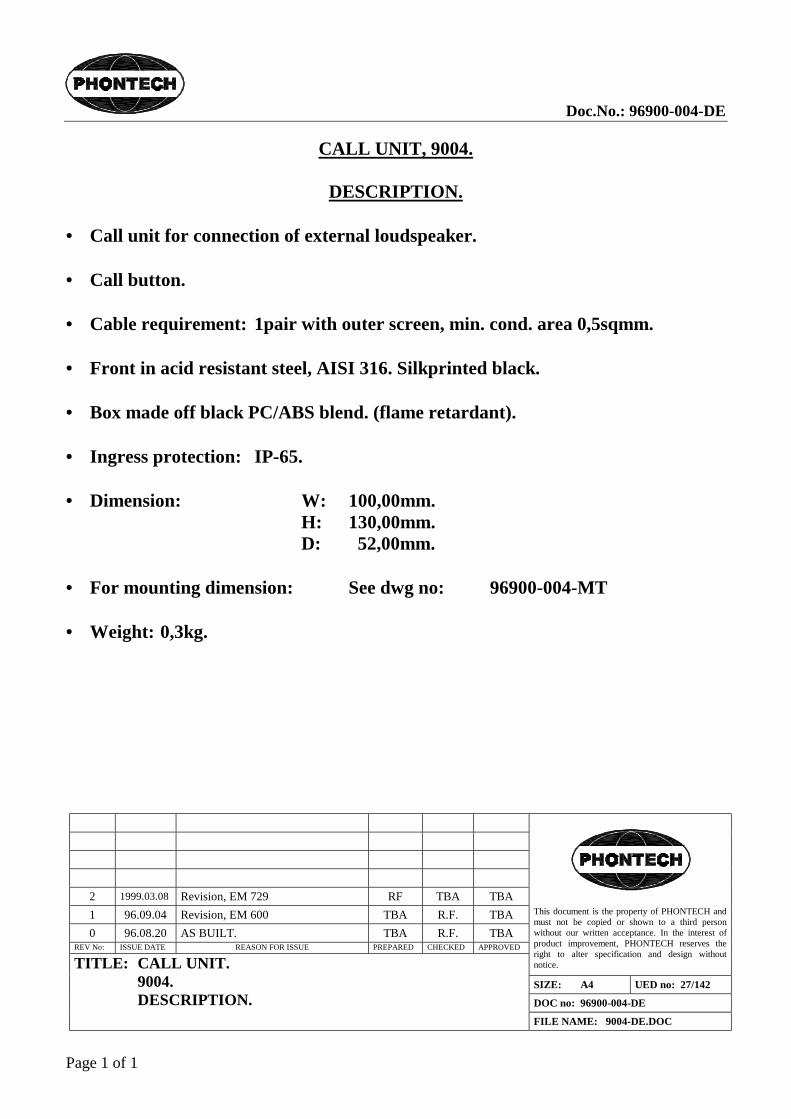
CALL UNIT, 9004.
DESCRIPTION.
• Call unit for connection of external loudspeaker. • Call button. • Cable requirement: 1pair with outer screen, min. cond. area 0,5sqmm. • Front in acid resistant steel, AISI 316. Silkprinted black. • Box made off black PC/ABS blend. (flame retardant). • Ingress protection: IP-65. • Dimension: W: 100,00mm.
H: 130,00mm. D: 52,00mm.
• For mounting dimension: See dwg no: 96900-004-MT • Weight: 0,3kg.


Doc.No.: 96900-009-DE
Page 1 of 1
2 2000.11.21 Revision, EM 816 RF TBA RF 1 96.09.04 Revision, EM 600 TBA R.F. TBA 0 96.08.20 AS BUILT. TBA R.F. TBA
REV No: ISSUE DATE REASON FOR ISSUE PREPARED CHECKED APPROVED
This document is the property of PHONTECH and must not be copied or shown to a third person without our written acceptance. In the interest of product improvement, PHONTECH reserves the right to alter specification and design without notice.
SIZE: A4 UED no: 27/142
DOC no: 96900-009-DE
TITLE: SUBSTATION. 9009. DESCRIPTION.
FILE NAME: 9009-DE.DOC
SUBSTATION, 9009.
DESCRIPTION.
• Substation with plug for external loudspeaker. • Call button. • Cable requirement: 1pair with outer screen, min. cond. area 0,5sqmm. • Front in acid resistant steel, AISI 316. Silk printed black. • Box made off PC/ABS blend. (flame retardant). • Ingress protection: IP-65. • Dimension: W: 100,00mm.
H: 130,00mm. D: 52,00mm.
• For mounting dimension: See dwg no: 96900-009-MT. • Weight: 0,3kg.


Doc.No.: 96900-011-DE
Page 1 of 1
2 1999.03.08 REVISION, EM 729 R.F. TBA RF 1 96.09.04 REVISION, EM 600 TBA R.F. TBA 0 96.08.20 AS BUILT. TBA R.F. TBA
REV No: ISSUE DATE REASON FOR ISSUE PREPARED CHECKED APPROVED
This document is the property of PHONTECH and must not be copied or shown to a third person without our written acceptance. In the interest of product improvement, PHONTECH reserves the right to alter specification and design without notice.
SIZE: A4 UED no: 27/142
DOC no: 96900-011-DE
TITLE: PLUGBOX. 9011. DESCRIPTION.
FILE NAME: 9011-DE.DOC
PLUGBOX, 9011.
DESCRIPTION.
• Plugbox with front mounted socket with 4 pins for microphone or headset. • Front in ACID RESISTANT STEEL, AISI 316. Silk printed black. • Box made off black PC/ABS blend. (flame retardant). • Ingress protection: IP-65. • Dimension: W: 100,00mm.
H: 130,00mm. D: 52,00mm.
• For mounting dimension: See dwg no: 96900-011-MT • Weight: 0,3kg.


Doc.No.: 96900-016-DE
Page 1 of 1
2 1999.03.08 REVISION, EM 729 R.F. TBA R.F. 1 96.09.04 REVISION, EM 600 TBA R.F. TBA 0 96.08.20 AS BUILT. TBA R.F. TBA
REV No: ISSUE DATE REASON FOR ISSUE PREPARED CHECKED APPROVED
This document is the property of PHONTECH and must not be copied or shown to a third person without our written acceptance. In the interest of product improvement, PHONTECH reserves the right to alter specification and design without notice.
SIZE: A4 UED no: 27/142
DOC no: 96900-016-DE
TITLE: SUBSTATION. 9016. DESCRIPTION.
FILE NAME: 9016-DE.DOC
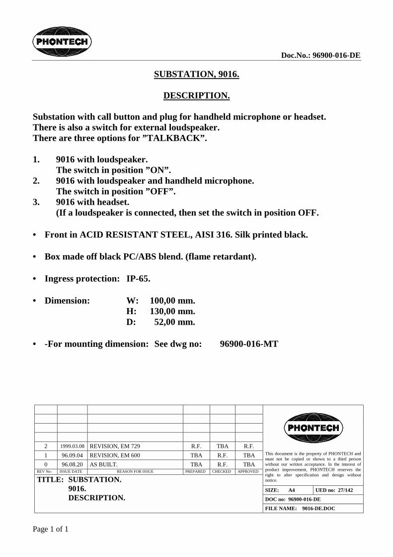
SUBSTATION, 9016.
DESCRIPTION.
Substation with call button and plug for handheld microphone or headset. There is also a switch for external loudspeaker. There are three options for ”TALKBACK”. 1. 9016 with loudspeaker.
The switch in position ”ON”. 2. 9016 with loudspeaker and handheld microphone.
The switch in position ”OFF”. 3. 9016 with headset.
(If a loudspeaker is connected, then set the switch in position OFF. • Front in ACID RESISTANT STEEL, AISI 316. Silk printed black. • Box made off black PC/ABS blend. (flame retardant). • Ingress protection: IP-65. • Dimension: W: 100,00 mm.
H: 130,00 mm. D: 52,00 mm.
• -For mounting dimension: See dwg no: 96900-016-MT


DNH reserves the right to alter specifications without notice. Rev. 23.02.2001
HP-10(T)N-3770 KragerøNORWAYPhone: ........ (47) 35 98 56 00Fax: ............ (47) 35 98 56 10E-mail: .............. [email protected]: ........www.dnh.noISO 9001 CERTIFIED
DNH WW Ltd. Phone: ......................................................(44) 1908 275 000England Fax: ..........................................................(44) 1908 275 100
E-mail: .......................................................... [email protected]
DNH GmbH Phone: .....................................................(49) 040 6569 30-0Germany Fax: .......................................................(49) 040 6569 30-30
E-mail: .............................................................. [email protected]
\\Ntserver2\dataark_2000\Horn\HP\HP10T.doc
Material / Colour........................................ ABS / RAL 7035Mounting .............................................................. BracketTermination .............................. Internal screw connectionsWeight ................................................................... 1,3 kgIP-rating ...................................................................... 56Max. / min. amb. temp .................................90 °C / -50 °CStandard version .......................... 50 V / 100 V transformerRated / max. power........................................10 W / 15 WSPL 1W/1m............................................................106 dBSPL rated power.....................................................116 dBEffective freq. range .................................... 410 – 8000 HzDispersion (-6dB) 1kHz / 4kHz ............................ 150° / 45°Directivity factor, Q (2kHz) ........................................... 7,4
Installation, Operation and Maintenance Procedures
� When mounting the loudspeaker please ensure that it is re-assembled in the same manner in which it wasreceived.
� To change the position of the loudspeaker please adjust the bracket (by loosening / tightening the screws) asrequired.
� For optimum performance, always use the correct voltage / power and operate within the frequency limits asstated.
� Do not open loudspeaker when energized.� Fasten lid with a torque of 1 - 2 Nm.� This loudspeaker is supplied with a 2 year warranty against defective workmanship.
Most of our products are available in different colors, impedances and power ratings.
1W/1m Pink Noise 1/3 octave bands
50/100 volt CombinedTransformer:
Primary connections:5 : 6 50 Volt line5 : 8 100 Volt line
Secondary nominaltappings:1 : 4 10,0 W1 : 3 5,0 W2 : 4 3,5 W1 : 2 2,5 W3 : 4 1,5 W2 : 3 0,8 W
Bracket and all outside nuts andbolts in stainless steel
M20
Cable diameter:6 - 12 mm

DNH reserves the right to alter specifications without notice. Rev. 14.05.2001
HP-15(T)N-3770 Kragerø NORWAY Phone: ........ (47) 35 98 56 00Fax: ............ (47) 35 98 56 10E-mail: .............. [email protected]: ........www.dnh.noISO 9001 CERTIFIED
DNH WW Ltd. Phone: ......................................................(44) 1908 275 000England Fax: ..........................................................(44) 1908 275 100 E-mail: .......................................................... [email protected]
DNH GmbH Phone: .....................................................(49) 040 6569 30-0Germany Fax: .......................................................(49) 040 6569 30-30 E-mail: .............................................................. [email protected]
\\Ntserver2\dataark_2000\Horn\HP\HP15T.doc
Material / Colour........................................ ABS / RAL 7035 Mounting .............................................................. Bracket Termination ................................. Inside screw connections Weight ................................................................... 1,7 kg IP-rating ...................................................................... 56 Max. / min. amb. temp .................................90 °C / -50 °C Standard version .......................... 50 V / 100 V transformer Rated / max. power........................................15 W / 20 W SPL 1W/1m............................................................108 dB SPL rated power.....................................................118 dB Effective freq. range .................................... 330 – 8000 Hz Dispersion (-6dB) 1kHz / 4kHz ............................ 130° / 35° Directivity factor, Q (2kHz) ........................................... 8,3
Installation, Operation and Maintenance Procedures
�� When mounting the loudspeaker please ensure that it is re-assembled in the same manner in which it was received.
�� To change the position of the loudspeaker please adjust the bracket (by loosening / tightening the screws) as required.
�� For optimum performance, always use the correct voltage / power and operate within the frequency limits as stated.
�� Do not open loudspeaker when energized. �� Fasten lid with a torque of 1 - 2 Nm. �� This loudspeaker is supplied with a 2 year warranty against defective workmanship. Most of our products are available in different colors, impedances and power ratings.
1W/1m Pink Noise 1/3 octave bands
50/100 volt Combined Transformer: Primary connections: 5 : 6 50 Volt line 5 : 8 100 Volt line Secondary nominal tappings: 1 : 4 15,0 W 1 : 3 7,5 W 2 : 4 5,0 W 1 : 2 4,0 W 3 : 4 2,0 W 2 : 3 0,8 W
Bracket and all outside nuts and bolts in stainless steel
M20
Cable diameter: 6 - 12 mm