3.1 starters and switches 3 product overview - eatonpub/@electrical/documents/conte… · v5-t3-2...
TRANSCRIPT
Volume 5—Motor Control and Protection CA08100006E—August 2015 www.eaton.com V5-T3-1
3
3
3
3
3
3
3
3
3
3
3
3
3
3
3
3
3
3
3
3
3
3
3
3
3
3
3
3
3
3
NEMA Manual Starters
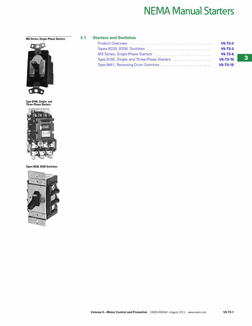
MS Series, Single-Phase Starters
Type B100, Single- and Three-Phase Starters
Types B230, B330 Switches
3.1 Starters and Switches
Product Overview . . . . . . . . . . . . . . . . . . . . . . . . . . . . . . . . . . . . . . . . V5-T3-2
Types B230, B330, Switches . . . . . . . . . . . . . . . . . . . . . . . . . . . . . . . . V5-T3-3
MS Series, Single-Phase Starters . . . . . . . . . . . . . . . . . . . . . . . . . . . . V5-T3-6
Type B100, Single- and Three-Phase Starters . . . . . . . . . . . . . . . . . . . V5-T3-10
Type 9441, Reversing Drum Switches . . . . . . . . . . . . . . . . . . . . . . . . . V5-T3-15
V5-T3-2 Volume 5—Motor Control and Protection CA08100006E—August 2015 www.eaton.com
3
3
3
3
3
3
3
3
3
3
3
3
3
3
3
3
3
3
3
3
3
3
3
3
3
3
3
3
3
3
3.1NEMA Manual Starters
Starters and Switches
Starters and Switches ContentsDescription Page
Starters and SwitchesTypes B230, B330, Switches . . . . . . . . . . . . . . V5-T3-3
MS Series, Single-Phase Starters . . . . . . . . . . V5-T3-6
Type B100, Single- and Three-Phase Starters . . . . . . . . . . . . . . . . . . . . . . . . . . . . . V5-T3-10
Type 9441, Reversing Drum Switches . . . . . . . V5-T3-15
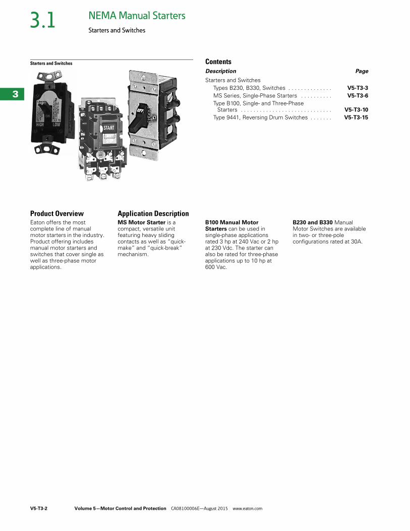
Product OverviewEaton offers the most complete line of manual motor starters in the industry. Product offering includes manual motor starters and switches that cover single as well as three-phase motor applications.
Application DescriptionMS Motor Starter is a compact, versatile unit featuring heavy sliding contacts as well as “quick-make” and “quick-break” mechanism.
B100 Manual Motor Starters can be used in single-phase applications rated 3 hp at 240 Vac or 2 hp at 230 Vdc. The starter can also be rated for three-phase applications up to 10 hp at 600 Vac.
B230 and B330 Manual Motor Switches are available in two- or three-pole configurations rated at 30A.
Volume 5—Motor Control and Protection CA08100006E—August 2015 www.eaton.com V5-T3-3
3
3
3
3
3
3
3
3
3
3
3
3
3
3
3
3
3
3
3
3
3
3
3
3
3
3
3
3
3
3
3.1NEMA Manual Starters
Starters and Switches
Types B230, B330 Switches ContentsDescription Page
Types B230, B330, Switches Product Selection . . . . . . . . . . . . . . . . . . . . . . . V5-T3-4
Wiring Diagrams . . . . . . . . . . . . . . . . . . . . . . . . V5-T3-4
Dimensions . . . . . . . . . . . . . . . . . . . . . . . . . . . V5-T3-5
MS Series, Single-Phase Starters . . . . . . . . . . . . . V5-T3-6
Type B100, Single- and Three-Phase Starters . . . . V5-T3-10
Type 9441, Reversing Drum Switches . . . . . . . . . . V5-T3-15
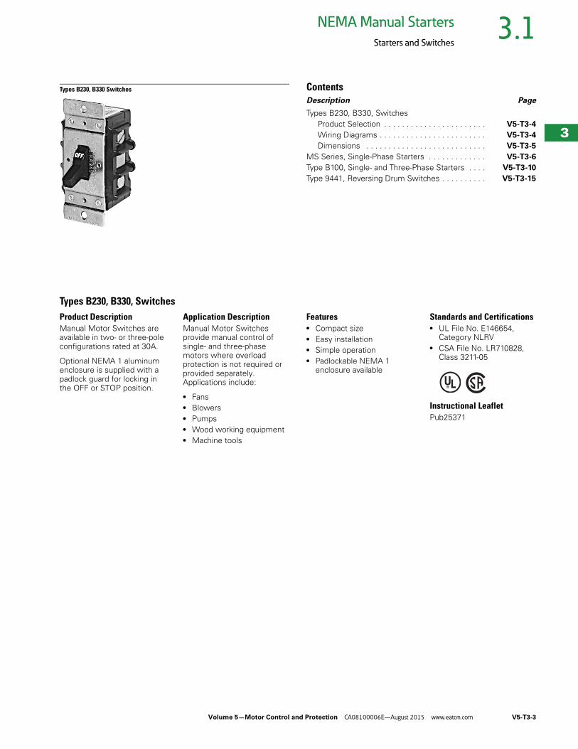
Types B230, B330, SwitchesProduct DescriptionManual Motor Switches are available in two- or three-pole configurations rated at 30A.
Optional NEMA 1 aluminum enclosure is supplied with a padlock guard for locking in the OFF or STOP position.
Application DescriptionManual Motor Switches provide manual control of single- and three-phase motors where overload protection is not required or provided separately. Applications include:
● Fans● Blowers● Pumps● Wood working equipment● Machine tools
Features● Compact size● Easy installation● Simple operation● Padlockable NEMA 1
enclosure available
Standards and Certifications● UL File No. E146654,
Category NLRV● CSA File No. LR710828,
Class 3211-05
Instructional LeafletPub25371
V5-T3-4 Volume 5—Motor Control and Protection CA08100006E—August 2015 www.eaton.com
3
3
3
3
3
3
3
3
3
3
3
3
3
3
3
3
3
3
3
3
3
3
3
3
3
3
3
3
3
3
3.1NEMA Manual Starters
Starters and Switches
Product Selection
When Ordering Specify● Catalog number of manual motor switch
Manual Motor Switches without Overload
Wiring Diagrams
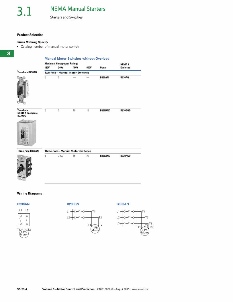
B230AN B230BN B330AN
Maximum Horsepower RatingsOpen
NEMA 1Enclosed120V 240V 480V 600V
Two-Pole—Manual Motor Switches
2 5 — — B230AN B230AG
2 5 10 15 B230BND B230BGD
Three-Pole—Manual Motor Switches
3 7-1/2 15 20 B330AND B330AGD
Two-Pole B230AN
Two-PoleNEMA 1 EnclosureB230BG
Three-Pole B330AN
L1 L2
T1 T21-Ph.Motor
L1 T1
L2 T2
T1 T21-Ph.Motor
L1 T1
L2 T2
L3 T3
T1 T3T2
3-Ph.Motor
Volume 5—Motor Control and Protection CA08100006E—August 2015 www.eaton.com V5-T3-5
3
3
3
3
3
3
3
3
3
3
3
3
3
3
3
3
3
3
3
3
3
3
3
3
3
3
3
3
3
3
3.1NEMA Manual Starters
Starters and Switches
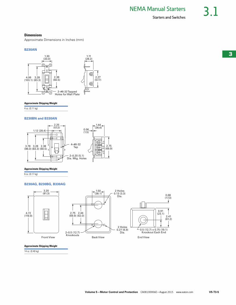
DimensionsApproximate Dimensions in Inches (mm)
B230AN
B230BN and B330AN
B230AG, B230BG, B330AG
2.38(60.5)
4.06(103.1)
3.28(83.3)
1.30(33.0)
2.27(57.7)
1.11(28.2)
2–#6-32 TappedHoles for Wall Plate
Approximate Shipping Weight
4 oz. (0.11 kg)
2–0.20 (5.1)Dia. Mtg. Holes
1.44(36.6)
0.06(1.5)
1.12 (28.4)
3.78(96.0)
3.28(83.3)
2.38(60.5)
2.75(69.9)
4–#6-32Tap
2.25(57.2)
Approximate Shipping Weight
6 oz. (0.17 kg)
2.41(61.2)
0.91(23.1)
0.68(17.3)
1.50(38.1)
2.44(62.0)
3.20(81.3)
4.72(119.9)
2.75(69.9)
2 Holes0.13 (3.3)
Dia.
2 Holes0.27 (6.9)
Dia.2–0.5 (12.7)Knockouts
Front View Back View End View
0.5 (12.7) x 0.75 (19.1)Knockout Each End
Approximate Shipping Weight
14 oz. (0.40 kg)
V5-T3-6 Volume 5—Motor Control and Protection CA08100006E—August 2015 www.eaton.com
3
3
3
3
3
3
3
3
3
3
3
3
3
3
3
3
3
3
3
3
3
3
3
3
3
3
3
3
3
3
3.1NEMA Manual Starters
Starters and Switches
MS Series, Single-Phase Starters ContentsDescription Page
Types B230, B330, Switches . . . . . . . . . . . . . . . . V5-T3-3
MS Series, Single-Phase Starters Product Selection . . . . . . . . . . . . . . . . . . . . . . . V5-T3-7
Accessories . . . . . . . . . . . . . . . . . . . . . . . . . . . V5-T3-9
Dimensions . . . . . . . . . . . . . . . . . . . . . . . . . . . V5-T3-9
Type B100, Single- and Three-Phase Starters . . . . V5-T3-10
Type 9441, Reversing Drum Switches . . . . . . . . . V5-T3-15
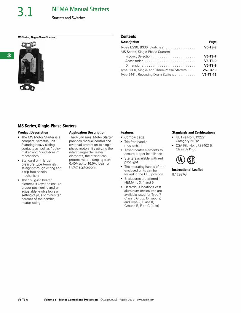
MS Series, Single-Phase StartersProduct Description● The MS Motor Starter is a
compact, versatile unit featuring heavy sliding contacts as well as “quick-make” and “quick-break” mechanism
● Standard with large pressure type terminals, straight-through wiring and a trip-free handle mechanism
● The “plug-in” heater element is keyed to ensure proper positioning and an adjustable knob allows a setting of plus or minus ten percent of the nominal heater rating
Application DescriptionThe MS Manual Motor Starter provides manual control and overload protection to single-phase motors. By utilizing the interchangeable heater elements, the starter can protect motors ranging from 0.40A up to 16.0A. Ideal for HVAC applications.
Features● Compact size● Trip-free handle
mechanism● Keyed heater elements to
ensure proper installation● Starters available with red
pilot light● The operating handle of the
enclosed units can be locked in the OFF position
● Enclosures are offered in NEMA 1, 3, 4 and 5
● Hazardous locations cast aluminum enclosures are available rated for Type 7, Class I, Group D (vapors) and Type 9, Class II, Groups E, F an G (dust)
Standards and Certifications● UL File No. E19222,
Category NLRV● CSA File No. LR39402-6,
Class 3211-05
Instructional LeafletIL12987G
Volume 5—Motor Control and Protection CA08100006E—August 2015 www.eaton.com V5-T3-7
3
3
3
3
3
3
3
3
3
3
3
3
3
3
3
3
3
3
3
3
3
3
3
3
3
3
3
3
3
3
3.1NEMA Manual Starters
Starters and Switches
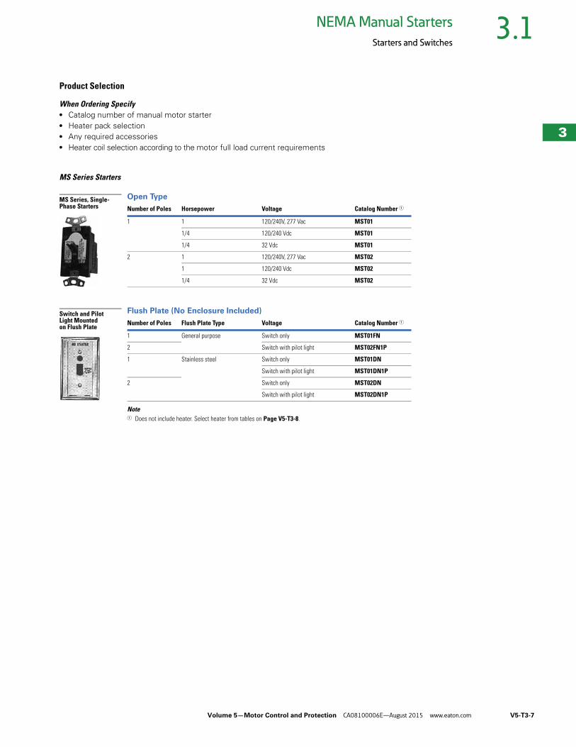
Product Selection
When Ordering Specify● Catalog number of manual motor starter● Heater pack selection● Any required accessories● Heater coil selection according to the motor full load current requirements
MS Series Starters
Open Type
Flush Plate (No Enclosure Included)
Note1 Does not include heater. Select heater from tables on Page V5-T3-8.
Number of Poles Horsepower Voltage Catalog Number 1
1 1 120/240V, 277 Vac MST01
1/4 120/240 Vdc MST01
1/4 32 Vdc MST01
2 1 120/240V, 277 Vac MST02
1 120/240 Vdc MST02
1/4 32 Vdc MST02
Number of Poles Flush Plate Type Voltage Catalog Number 1
1 General purpose Switch only MST01FN
2 Switch with pilot light MST02FN1P
1 Stainless steel Switch only MST01DN
Switch with pilot light MST01DN1P
2 Switch only MST02DN
Switch with pilot light MST02DN1P
MS Series, Single-Phase Starters
Switch and Pilot Light Mounted on Flush Plate
V5-T3-8 Volume 5—Motor Control and Protection CA08100006E—August 2015 www.eaton.com
3
3
3
3
3
3
3
3
3
3
3
3
3
3
3
3
3
3
3
3
3
3
3
3
3
3
3
3
3
3
3.1NEMA Manual Starters
Starters and Switches
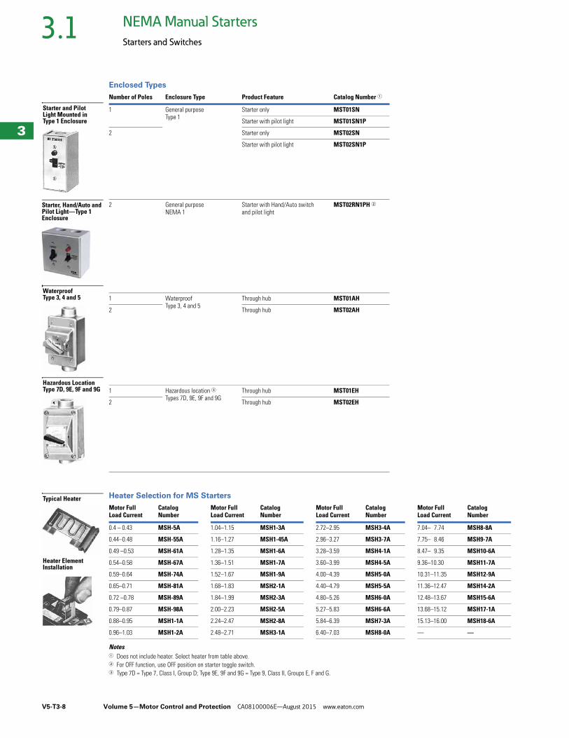
Enclosed Types
Heater Selection for MS Starters
Notes1 Does not include heater. Select heater from table above.2 For OFF function, use OFF position on starter toggle switch. 3 Type 7D = Type 7, Class I, Group D; Type 9E, 9F and 9G = Type 9, Class II, Groups E, F and G.
Number of Poles Enclosure Type Product Feature Catalog Number 1
1 General purposeType 1
Starter only MST01SN
Starter with pilot light MST01SN1P
2 Starter only MST02SN
Starter with pilot light MST02SN1P
2 General purposeNEMA 1
Starter with Hand/Auto switch and pilot light
MST02RN1PH 2
1 WaterproofType 3, 4 and 5
Through hub MST01AH
2 Through hub MST02AH
1 Hazardous location 3Types 7D, 9E, 9F and 9G
Through hub MST01EH
2 Through hub MST02EH
Motor Full Load Current
CatalogNumber
Motor FullLoad Current
CatalogNumber
Motor FullLoad Current
CatalogNumber
Motor Full Load Current
CatalogNumber
0.4 – 0.43 MSH-5A 1.04–1.15 MSH1-3A 2.72–2.95 MSH3-4A 7.04– 7.74 MSH8-8A
0.44–0.48 MSH-55A 1.16–1.27 MSH1-45A 2.96–3.27 MSH3-7A 7.75– 8.46 MSH9-7A
0.49 –0.53 MSH-61A 1.28–1.35 MSH1-6A 3.28–3.59 MSH4-1A 8.47– 9.35 MSH10-6A
0.54–0.58 MSH-67A 1.36–1.51 MSH1-7A 3.60–3.99 MSH4-5A 9.36–10.30 MSH11-7A
0.59–0.64 MSH-74A 1.52–1.67 MSH1-9A 4.00–4.39 MSH5-0A 10.31–11.35 MSH12-9A
0.65–0.71 MSH-81A 1.68–1.83 MSH2-1A 4.40–4.79 MSH5-5A 11.36–12.47 MSH14-2A
0.72 –0.78 MSH-89A 1.84–1.99 MSH2-3A 4.80–5.26 MSH6-0A 12.48–13.67 MSH15-6A
0.79–0.87 MSH-98A 2.00–2.23 MSH2-5A 5.27–5.83 MSH6-6A 13.68–15.12 MSH17-1A
0.88–0.95 MSH1-1A 2.24–2.47 MSH2-8A 5.84–6.39 MSH7-3A 15.13–16.00 MSH18-6A
0.96–1.03 MSH1-2A 2.48–2.71 MSH3-1A 6.40–7.03 MSH8-0A — —
Starter and PilotLight Mounted in Type 1 Enclosure
Waterproof Type 3, 4 and 5
Hazardous Location Type 7D, 9E, 9F and 9G
Starter, Hand/Auto and Pilot Light—Type 1 Enclosure
Typical Heater
Heater Element Installation
Volume 5—Motor Control and Protection CA08100006E—August 2015 www.eaton.com V5-T3-9
3
3
3
3
3
3
3
3
3
3
3
3
3
3
3
3
3
3
3
3
3
3
3
3
3
3
3
3
3
3
3.1NEMA Manual Starters
Starters and Switches
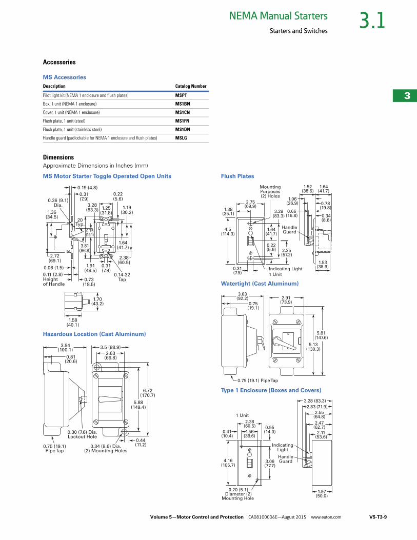
Accessories
MS Accessories
DimensionsApproximate Dimensions in Inches (mm)
MS Motor Starter Toggle Operated Open Units
Hazardous Location (Cast Aluminum)
Flush Plates
Watertight (Cast Aluminum)
Type 1 Enclosure (Boxes and Covers)
Description Catalog Number
Pilot light kit (NEMA 1 enclosure and flush plates) MSPT
Box, 1 unit (NEMA 1 enclosure) MS1BN
Cover, 1 unit (NEMA 1 enclosure) MS1CN
Flush plate, 1 unit (steel) MS1FN
Flush plate, 1 unit (stainless steel) MS1DN
Handle guard (padlockable for NEMA 1 enclosure and flush plates) MSLG
1.36(34.5)
0.31(7.9)
1.25(31.8)
3.28(83.3)
3.81(96.8)
0.75(19.1)
0.22(5.6)
1.64(41.7)
1.19(30.2)
2.38(60.5)
0.14-32Tap
20Typ.
0.31(7.9)
0.06 (1.5)
0.11 (2.8)Heightof Handle
0.73(18.5)
1.91(48.5)
0.19 (4.8)
0.36 (9.1)Dia.
2.72(69.1)
1.70(43.2)
1.58(40.1)
0.75 (19.1)Pipe Tap
0.30 (7.6) Dia.Lockout Hole
0.81(20.6)
3.94(100.1)
2.63(66.8)
0.44(11.2)
3.5 (88.9)
5.88(149.4)
6.72(170.7)
0.34 (8.6) Dia.(2) Mounting Holes
0.31(7.9) 1 Unit
0.22(5.6) 2.25
(57.2)
1.64(41.7)
Indicating Light
HandleGuard
MountingPurposes(2) Holes
1.38(35.1)
0.34(8.6)
0.66(16.8)
0.78(19.8)
1.06(26.9)
1.64(41.7)
1.52(38.6)
2.75(69.9)
3.28(83.3)
4.5(114.3)
1.53(38.9)
0.75 (19.1) Pipe Tap
0.75(19.1)
3.63(92.2)
5.13(130.3)
5.81(147.6)
2.91(73.9)
1 Unit
3.28 (83.3)
3.06(77.7)
IndicatingLight
HandleGuard
1.56(39.6)
0.55(14.0)
2.47(62.7)
2.11(53.6)
2.55(64.8)
2.83 (71.9)
2.38(60.5)
4.16(105.7)
1.97(50.0)
0.41(10.4)
0.20 (5.1)Diameter (2)
Mounting Hole
V5-T3-10 Volume 5—Motor Control and Protection CA08100006E—August 2015 www.eaton.com
3
3
3
3
3
3
3
3
3
3
3
3
3
3
3
3
3
3
3
3
3
3
3
3
3
3
3
3
3
3
3.1NEMA Manual Starters
Starters and Switches
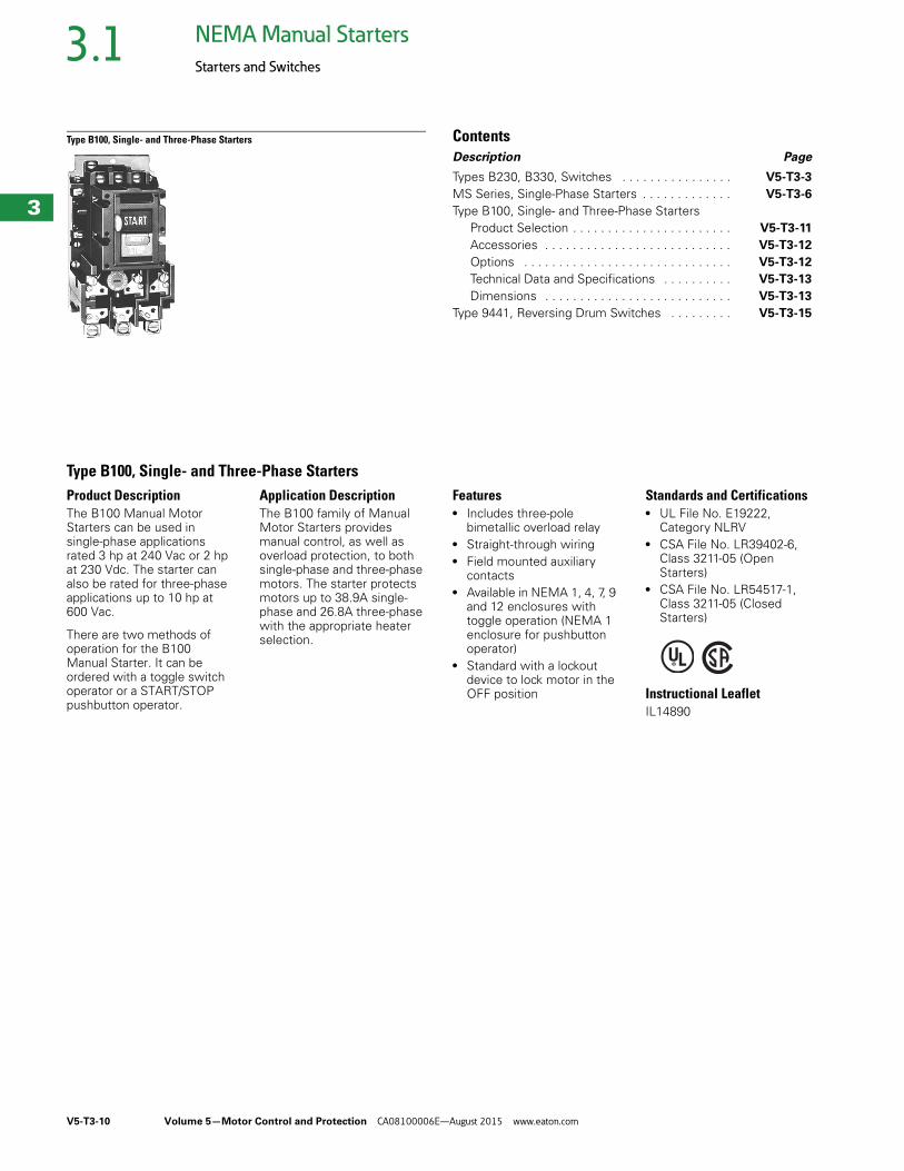
Type B100, Single- and Three-Phase Starters ContentsDescription Page
Types B230, B330, Switches . . . . . . . . . . . . . . . . V5-T3-3
MS Series, Single-Phase Starters . . . . . . . . . . . . . V5-T3-6
Type B100, Single- and Three-Phase Starters Product Selection . . . . . . . . . . . . . . . . . . . . . . . V5-T3-11
Accessories . . . . . . . . . . . . . . . . . . . . . . . . . . . V5-T3-12
Options . . . . . . . . . . . . . . . . . . . . . . . . . . . . . . V5-T3-12
Technical Data and Specifications . . . . . . . . . . V5-T3-13
Dimensions . . . . . . . . . . . . . . . . . . . . . . . . . . . V5-T3-13
Type 9441, Reversing Drum Switches . . . . . . . . . V5-T3-15
Type B100, Single- and Three-Phase StartersProduct DescriptionThe B100 Manual Motor Starters can be used in single-phase applications rated 3 hp at 240 Vac or 2 hp at 230 Vdc. The starter can also be rated for three-phase applications up to 10 hp at 600 Vac.
There are two methods of operation for the B100 Manual Starter. It can be ordered with a toggle switch operator or a START/STOP pushbutton operator.
Application DescriptionThe B100 family of Manual Motor Starters provides manual control, as well as overload protection, to both single-phase and three-phase motors. The starter protects motors up to 38.9A single-phase and 26.8A three-phase with the appropriate heater selection.
Features● Includes three-pole
bimetallic overload relay● Straight-through wiring● Field mounted auxiliary
contacts● Available in NEMA 1, 4, 7, 9
and 12 enclosures with toggle operation (NEMA 1 enclosure for pushbutton operator)
● Standard with a lockout device to lock motor in the OFF position
Standards and Certifications● UL File No. E19222,
Category NLRV● CSA File No. LR39402-6,
Class 3211-05 (Open Starters)
● CSA File No. LR54517-1, Class 3211-05 (Closed Starters)
Instructional LeafletIL14890

Volume 5—Motor Control and Protection CA08100006E—August 2015 www.eaton.com V5-T3-11
3
3
3
3
3
3
3
3
3
3
3
3
3
3
3
3
3
3
3
3
3
3
3
3
3
3
3
3
3
3
3.1NEMA Manual Starters
Starters and Switches
Product Selection
When Ordering Specify● Catalog number of
Starter with application modifications
● Heater pack selection—a three-phase starter requires three heaters, and a single-phase starter requires two heaters
● Any required accessories
Toggle and Pushbutton Operated Starters
Heater Selection—Single-Phase Enclosed Starters 5
Notes1 One 1 in chrome hub supplied on each end.2 NEMA 7D = NEMA 7, Class I, Group D. NEMA 9E, 9F and 9G = NEMA 9, Class II, Groups E, F and G.3 Tapped for 1 in conduit on each end.4 Starter does not include heaters. Select catalog numbers of heaters from table on Page V5-T3-12.5 Single-phase starters require two overload heaters.
NEMASize
Open TypeToggle Handle
Enclosed
NEMA 1General Purpose
NEMA 4Watertight,Stainless Steel 1
NEMA 7D,9E, 9F and 9G for HazardousLocations 23
NEMA 12Dust-Tight
CatalogNumber 4
CatalogNumber 4
CatalogNumber 4
CatalogNumber 4
CatalogNumber 4
Type B100 Non-Reversing Two-Pole (For Single-Phase Motors and DC)
M-0 B100M0B B100S0B B100W0B B100U0B B100J0B
M-1 B100M1B B100S1B B100W1B B100U1B B100J1B
Type B100 Non-Reversing Three-Pole (For Polyphase Motors) 4
M-0 B100M0C B100S0C B100W0C B100U0C B100J0C
M-1 B100M1C B100S1C B100W1C B100U1C B100J1C
Motor Full Load Current
MaximumFuse Amps
Catalog Number
Motor Full Load Current
MaximumFuse Amps
Catalog Number
Motor Full Load Current
MaximumFuse Amps
Catalog Number
0.28–0.29 1 FH03 1.90–2.10 7 FH22 9.59–10.40 35 FH40
0.30–0.33 1 FH04 2.11–2.32 8 FH23 10.41–11.30 35 FH41
0.34–0.36 1 FH05 2.33–2.54 8 FH24 11.40–12.20 40 FH42
0.37–0.40 1 FH06 2.55–2.79 9 FH25 12.30–13.50 45 FH43
0.41–0.45 1 FH07 2.80–3.07 10 FH26 13.60–14.90 50 FH44
0.46–0.50 1 FH08 3.08–3.36 10 FH27 15.00–16.00 50 FH45
0.51–0.56 1 FH09 3.37–3.68 10 FH28 16.10–17.10 60 FH46
0.57–0.63 2 FH10 3.69–4.03 10 FH29 17.20–18.30 60 FH47
0.64–0.70 2 FH11 4.04–4.40 15 FH30 18.40–19.70 70 FH48
0.71–0.78 2 FH12 4.41–4.81 15 FH31 19.80–21.20 70 FH49
0.79–0.86 2 FH13 4.82–5.26 15 FH32 21.30–22.80 80 FH50
0.87–0.95 3 FH14 5.27–5.74 15 FH33 22.90–24.50 88 FH51
0.96–1.04 3 FH15 5.75–6.26 20 FH34 24.60–26.40 90 FH52
1.05–1.14 3 FH16 6.27–6.83 20 FH35 26.50–28.50 90 FH53
1.15–1.25 4 FH17 6.84–7.45 25 FH36 28.60–30.80 100 FH54
1.26–1.39 4 FH18 7.46–8.11 25 FH37 30.90–33.30 110 FH55
1.40–1.54 5 FH19 8.12–8.81 30 FH38 33.40–36.00 125 FH56
1.55–1.71 5 FH20 8.82–9.58 30 FH39 36.10–38.90 125 FH57
1.72–1.89 6 FH21 — — — — — —
Toggle Operated
Type 1 Enclosure
V5-T3-12 Volume 5—Motor Control and Protection CA08100006E—August 2015 www.eaton.com
3
3
3
3
3
3
3
3
3
3
3
3
3
3
3
3
3
3
3
3
3
3
3
3
3
3
3
3
3
3
3.1NEMA Manual Starters
Starters and Switches
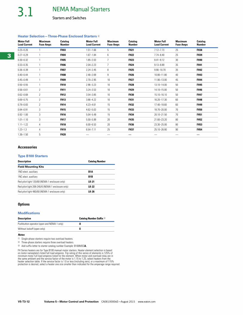
Heater Selection—Three-Phase Enclosed Starters 2
Accessories
Type B100 Starters
Options
Modifications
Notes1 Single-phase starters require two overload heaters.2 Three-phase starters require three overload heaters.3 Add suffix letter to starter catalog number Example: B100MOCA.
FH Series heaters are for Type B100 manual motor starters. Heater element selection is based on motor nameplate’s listed full load amperes. Trip rating of this series of elements is 125% of minimum motor full load amperes listed for the element. When motor and overload relay are in the same ambient and the service factor of the motor is 1.15 to 1.25, select heaters from the heater selection table. If the service factor is 1.0 or less (including zero), or a maximum of 115% protection is desired, select a heater one size smaller than indicated for the amperage range required.
Motor Full Load Current
MaximumFuse Amps
Catalog Number
Motor Full Load Current
MaximumFuse Amps
Catalog Number
Motor Full Load Current
MaximumFuse Amps
Catalog Number
0.25–0.26 1 FH03 1.51–1.66 5 FH21 7.12–7.73 25 FH38
0.27–0.29 1 FH04 1.67–1.84 6 FH22 7.74–8.40 25 FH39
0.30–0.32 1 FH05 1.85–2.03 7 FH23 8.41–9.12 30 FH40
0.33–0.35 1 FH06 2.04–2.23 7 FH24 9.13–9.89 35 FH41
0.36–0.39 1 FH07 2.24–2.45 8 FH25 9.90–10.70 35 FH42
0.40–0.44 1 FH08 2.46–2.69 9 FH26 10.80–11.80 40 FH43
0.45–0.49 1 FH09 2.70–2.95 10 FH27 11.90–13.00 45 FH44
0.50–0.55 1 FH10 2.96–3.23 10 FH28 13.10–14.00 50 FH45
0.56–0.61 2 FH11 3.24–3.53 10 FH29 14.10–15.00 50 FH46
0.62–0.68 2 FH12 3.54–3.85 10 FH30 15.10–16.10 50 FH47
0.69–0.75 2 FH13 3.86–4.22 10 FH31 16.20–17.30 60 FH48
0.78–0.83 2 FH14 4.23–4.61 15 FH32 17.40–18.60 60 FH49
0.84–0.91 3 FH15 4.62–5.03 15 FH33 18.70–20.00 70 FH50
0.92–1.00 3 FH16 5.04–5.49 15 FH34 20.10–21.50 70 FH51
1.01–1.10 3 FH17 5.50–5.99 20 FH35 21.60–23.20 80 FH52
1.11–1.22 4 FH18 6.00–6.53 20 FH36 23.30–25.00 80 FH53
1.23–1.3 4 FH19 6.54–7.11 25 FH37 25.10–26.80 90 FH54
1.36–1.50 5 FH20 — — — — — —
Description Catalog Number
Field Mounting Kits
1NO elect. auxiliary B1A
1NC elect. auxiliary B1B
Red pilot light 120/60 (NEMA 1 enclosure only) LK-21
Red pilot light 208-240/6 (NEMA 1 enclosure only) LK-22
Red pilot light 480/60 (NEMA 1 enclosure only) LK-26
Description Catalog Number Suffix 3
Pushbutton operator (open and NEMA 1 only) A
Without lockoff (open only) X
Volume 5—Motor Control and Protection CA08100006E—August 2015 www.eaton.com V5-T3-13
3
3
3
3
3
3
3
3
3
3
3
3
3
3
3
3
3
3
3
3
3
3
3
3
3
3
3
3
3
3
3.1NEMA Manual Starters
Starters and Switches
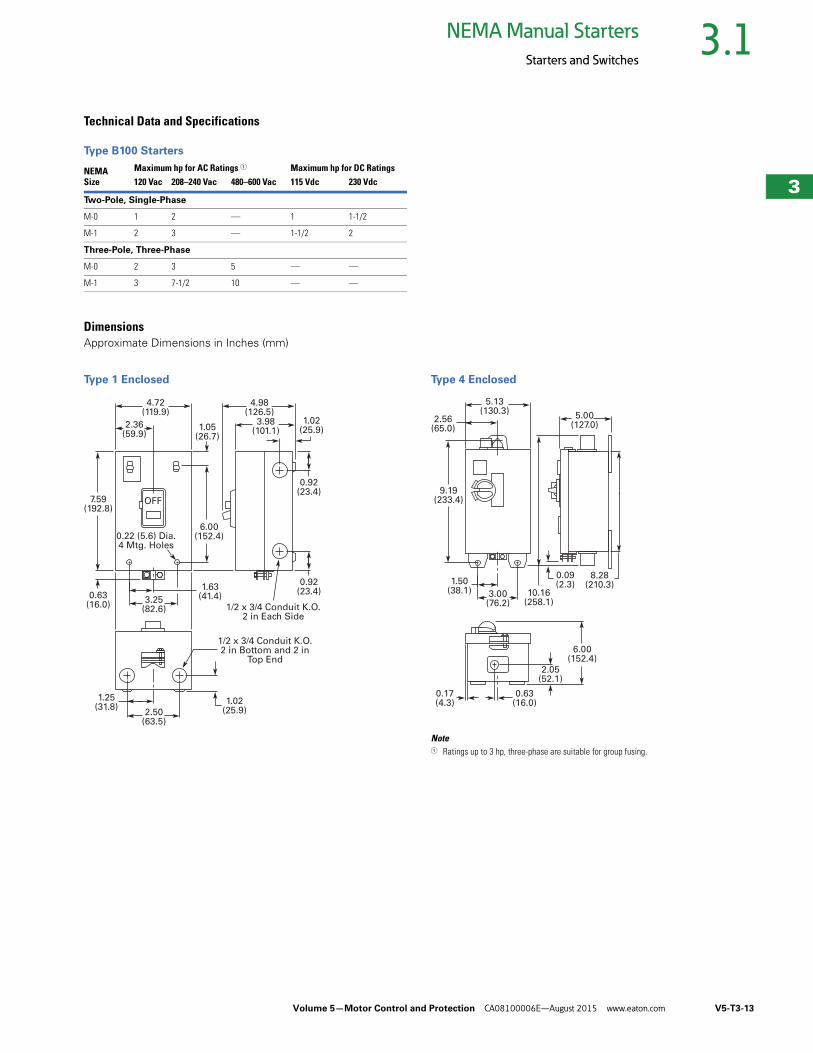
Technical Data and Specifications
Type B100 Starters
DimensionsApproximate Dimensions in Inches (mm)
Type 1 Enclosed Type 4 Enclosed
Note1 Ratings up to 3 hp, three-phase are suitable for group fusing.
NEMASize
Maximum hp for AC Ratings 1 Maximum hp for DC Ratings120 Vac 208–240 Vac 480–600 Vac 115 Vdc 230 Vdc
Two-Pole, Single-Phase
M-0 1 2 — 1 1-1/2
M-1 2 3 — 1-1/2 2
Three-Pole, Three-Phase
M-0 2 3 5 — —
M-1 3 7-1/2 10 — —
1.02(25.9)
1/2 x 3/4 Conduit K.O.2 in Bottom and 2 in
Top End
1/2 x 3/4 Conduit K.O.2 in Each Side
0.92(23.4)
0.92(23.4)
6.00(152.4)
1.05(26.7)
7.59(192.8)
0.63(16.0)
4.72(119.9)
4.98(126.5)
3.98(101.1)
1.02(25.9)
2.36(59.9)
3.25(82.6)
1.63(41.4)
2.50(63.5)
1.25(31.8)
OFF
0.22 (5.6) Dia.4 Mtg. Holes
0.09(2.3)
9.19(233.4)
0.17(4.3)
2.05(52.1)
5.13(130.3)
5.00(127.0)
2.56(65.0)
3.00(76.2)
1.50(38.1)
6.00(152.4)
8.28(210.3)
10.16(258.1)
0.63(16.0)
V5-T3-14 Volume 5—Motor Control and Protection CA08100006E—August 2015 www.eaton.com
3
3
3
3
3
3
3
3
3
3
3
3
3
3
3
3
3
3
3
3
3
3
3
3
3
3
3
3
3
3
3.1NEMA Manual Starters
Starters and Switches
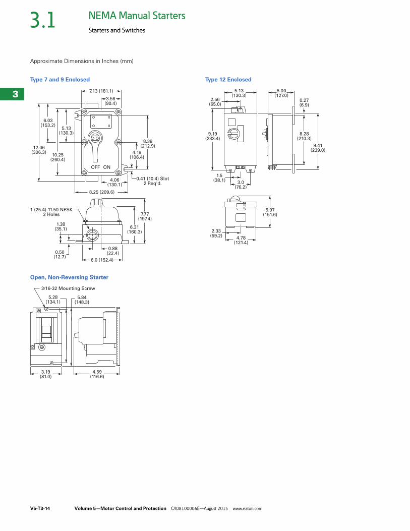
Approximate Dimensions in Inches (mm)
Type 7 and 9 Enclosed
Open, Non-Reversing Starter
Type 12 Enclosed
12.06(306.3)
6.03(153.2)
10.25(260.4)
5.13(130.3)
0.50(12.7)
1.38(35.1)
1 (25.4)-11.50 NPSK2 Holes
7.13 (181.1)
3.56(90.4)
6.0 (152.4)
8.25 (209.6)
7.77(197.4)
6.31(160.3)
8.38(212.9)
0.41 (10.4) Slot2 Req'd.
4.06(130.1)
4.19(106.4)
OFF ON
0.88(22.4)
3.19(81.0)
4.59(116.6)
5.84(148.3)
5.28(134.1)
3/16-32 Mounting Screw
9.19(233.4)
5.13(130.3)
5.00(127.0)
2.56(65.0)
3.0(76.2)
1.5(38.1)
4.78(121.4)
2.33(59.2)
5.97(151.6)
8.28(210.3)
0.27(6.9)
9.41(239.0)
Volume 5—Motor Control and Protection CA08100006E—August 2015 www.eaton.com V5-T3-15
3
3
3
3
3
3
3
3
3
3
3
3
3
3
3
3
3
3
3
3
3
3
3
3
3
3
3
3
3
3
3.1NEMA Manual Starters
Starters and Switches
Type 9441, Reversing Drum Switches ContentsDescription Page
Types B230, B330, Switches . . . . . . . . . . . . . . . . . V5-T3-3
MS Series, Single-Phase Starters . . . . . . . . . . . . . V5-T3-6
Type B100, Single- and Three-Phase Starters . . . . V5-T3-10
Type 9441, Reversing Drum Switches Product Selection . . . . . . . . . . . . . . . . . . . . . . . V5-T3-16
Wiring Diagrams . . . . . . . . . . . . . . . . . . . . . . . . V5-T3-17
Dimensions . . . . . . . . . . . . . . . . . . . . . . . . . . . V5-T3-17
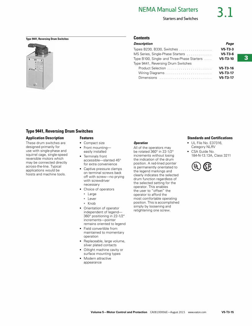
Type 9441, Reversing Drum SwitchesApplication DescriptionThese drum switches are designed primarily for use with single-phase and squirrel cage, single-speed reversible motors which may be connected directly across-the-line. Typical applications would be hoists and machine tools.
Features● Compact size● Front mounting—
easily installed● Terminals front
accessible—slanted 45° for extra convenience
● Captive pressure clamps on terminal screws back off with screw—no prying with screwdriver necessary
● Choice of operators ● Large● Lever● Knob
● Orientation of operator independent of legend—360° positioning in 22-1/2° increments—pointer remains oriented to legend
● Field convertible from maintained to momentary operation
● Replaceable, large volume, silver plated contacts
● Oiltight machine cavity or surface mounting types
● Modern attractive appearance
OperationAll of the operators may be rotated 360° in 22-1/2° increments without losing the indication of the drum position. A red-lined pointer is permanently orientated to the legend markings and clearly indicates the selected drum function regardless of the selected setting for the operator. This enables the user to “offset” the operator to afford the most comfortable operating position. This is accomplished simply by loosening and retightening one screw.
Standards and Certifications● UL File No. E37316,
Category NLRV● CSA Guide No.
184-N-13.13A, Class 3211
V5-T3-16 Volume 5—Motor Control and Protection CA08100006E—August 2015 www.eaton.com
3
3
3
3
3
3
3
3
3
3
3
3
3
3
3
3
3
3
3
3
3
3
3
3
3
3
3
3
3
3
3.1NEMA Manual Starters
Starters and Switches
Product Selection
When Ordering Specify● Catalog number
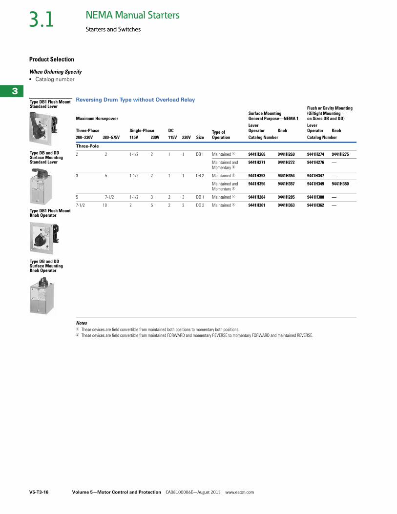
Reversing Drum Type without Overload Relay
Notes1 These devices are field convertible from maintained both positions to momentary both positions.2 These devices are field convertible from maintained FORWARD and momentary REVERSE to momentary FORWARD and maintained REVERSE.
Maximum Horsepower
SizeType ofOperation
Surface MountingGeneral Purpose—NEMA 1
Flush or Cavity Mounting(Oiltight Mountingon Sizes DB and DD)
Three-Phase Single-Phase DCLever Operator Knob
Lever Operator Knob
200–230V 380–575V 115V 230V 115V 230V Catalog Number Catalog Number
Three-Pole
2 2 1-1/2 2 1 1 DB 1 Maintained 1 9441H268 9441H269 9441H274 9441H275
Maintained and Momentary 2
9441H271 9441H272 9441H276 —
3 5 1-1/2 2 1 1 DB 2 Maintained 1 9441H353 9441H354 9441H347 —
Maintained and Momentary 2
9441H356 9441H357 9441H349 9441H350
5 7-1/2 1-1/2 3 2 3 DD 1 Maintained 1 9441H284 9441H285 9441H388 —
7-1/2 10 2 5 2 3 DD 2 Maintained 1 9441H361 9441H363 9441H362 —
Type DB1 Flush Mount Standard Lever
Type DB and DD Surface Mounting Standard Lever
Type DB1 Flush Mount Knob Operator
Type DB and DD Surface Mounting Knob Operator
Volume 5—Motor Control and Protection CA08100006E—August 2015 www.eaton.com V5-T3-17
3
3
3
3
3
3
3
3
3
3
3
3
3
3
3
3
3
3
3
3
3
3
3
3
3
3
3
3
3
3
3.1NEMA Manual Starters
Starters and Switches
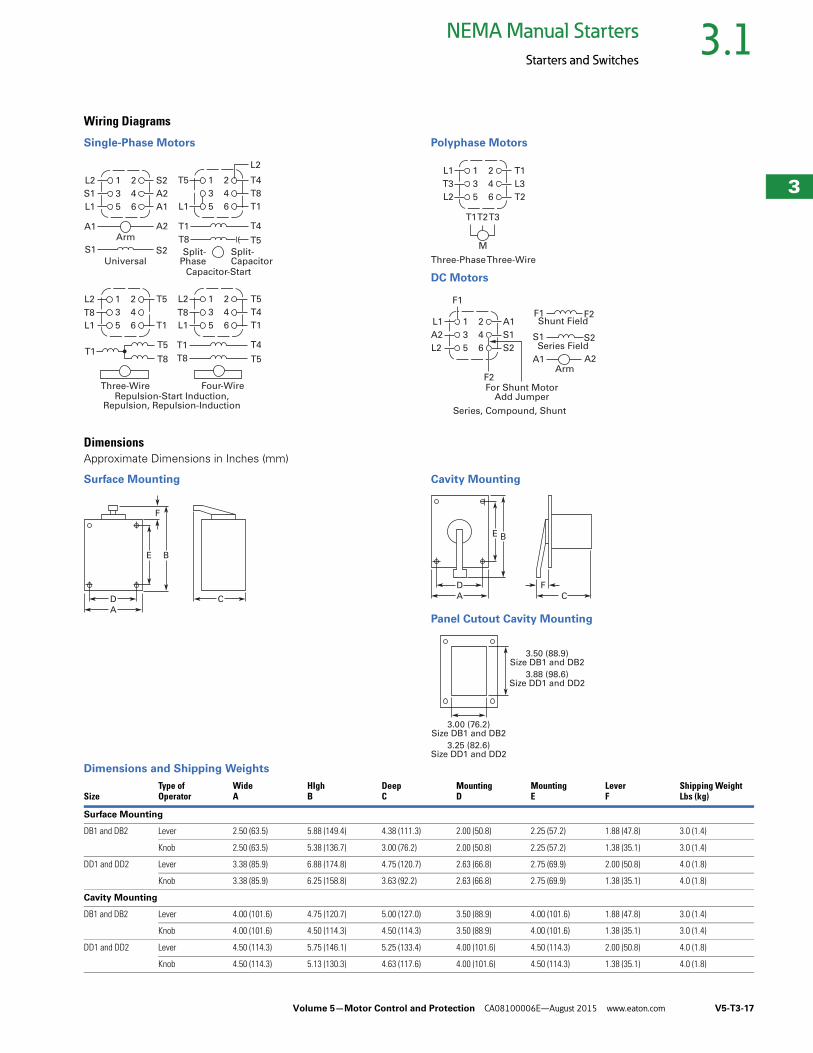
Wiring Diagrams
Single-Phase Motors Polyphase Motors
DC Motors
DimensionsApproximate Dimensions in Inches (mm)
Surface Mounting Cavity Mounting
Panel Cutout Cavity Mounting
Dimensions and Shipping Weights
L2
S1
L1
A1
S1
1
3
5
2
4
6
S2
A2
A1
A2
S2
Arm
T5
L1
T1
T8
Split-Phase
1
3
5
2
4
6
T4
L2
T8
T1
T4
T5
Split-Capacitor
Capacitor-StartUniversal
L2
T8
L1
1
3
5
2
4
6
T5
T1
T5
T8
Three-Wire
T1
L2
T8
L1
T1
T8
1
3
5
2
4
6
T5
T4
T1
T4
T5
Four-WireRepulsion-Start Induction,
Repulsion, Repulsion-Induction
Three-Phase Three-Wire
L1
T3
L2
T1 T3T2
1
3
5
2
4
6
T1
L3
T2
M
Series, Compound, Shunt
L1
F1
F2
A2
L2
1
3
5
2
4
6
A1
S1
S2
For Shunt MotorAdd Jumper
Shunt Field
Series FieldS1 S2
F1 F2
A1 A2Arm
E
CD
B
F
A
BE
C
D F
A
3.50 (88.9)Size DB1 and DB2
3.00 (76.2)Size DB1 and DB2
3.88 (98.6)Size DD1 and DD2
3.25 (82.6)Size DD1 and DD2
SizeType ofOperator
WideA
HIghB
DeepC
MountingD
MountingE
LeverF
Shipping WeightLbs (kg)
Surface Mounting
DB1 and DB2 Lever 2.50 (63.5) 5.88 (149.4) 4.38 (111.3) 2.00 (50.8) 2.25 (57.2) 1.88 (47.8) 3.0 (1.4)
Knob 2.50 (63.5) 5.38 (136.7) 3.00 (76.2) 2.00 (50.8) 2.25 (57.2) 1.38 (35.1) 3.0 (1.4)
DD1 and DD2 Lever 3.38 (85.9) 6.88 (174.8) 4.75 (120.7) 2.63 (66.8) 2.75 (69.9) 2.00 (50.8) 4.0 (1.8)
Knob 3.38 (85.9) 6.25 (158.8) 3.63 (92.2) 2.63 (66.8) 2.75 (69.9) 1.38 (35.1) 4.0 (1.8)
Cavity Mounting
DB1 and DB2 Lever 4.00 (101.6) 4.75 (120.7) 5.00 (127.0) 3.50 (88.9) 4.00 (101.6) 1.88 (47.8) 3.0 (1.4)
Knob 4.00 (101.6) 4.50 (114.3) 4.50 (114.3) 3.50 (88.9) 4.00 (101.6) 1.38 (35.1) 3.0 (1.4)
DD1 and DD2 Lever 4.50 (114.3) 5.75 (146.1) 5.25 (133.4) 4.00 (101.6) 4.50 (114.3) 2.00 (50.8) 4.0 (1.8)
Knob 4.50 (114.3) 5.13 (130.3) 4.63 (117.6) 4.00 (101.6) 4.50 (114.3) 1.38 (35.1) 4.0 (1.8)