308221b pro-wash gun washer - graco inc. gun washer model 110–484, series a 100 psi (7 bar)...
TRANSCRIPT

INSTRUCTIONS–PARTS LIST 308–221This manual contains IMPORT ANTWARNINGS AND INSTRUCTIONS
READ AND RETAIN FOR REFERENCE
Rev BSupercedes A
PRO-WASH� GUN WASHERModel 110–484, Series A100 psi (7 bar) MAXIMUM WORKING PRESSUREWith Mini-Flo� Supply Pump (Model 217–588) and plas-tic fluid tank; two gun capacity
Model 110–485, Series A100 psi (7 bar) MAXIMUM WORKING PRESSUREWith Husky� 715 Pump (Model 220–617) and plasticfluid tank; two gun capacity
Model 110–486, Series A100 psi (7 bar) MAXIMUM WORKING PRESSUREWith Husky� 715 Pump (Model 220–617) and stainlesssteel fluid tank; four gun capacity
Model 110–487, Series A100 psi (7 bar) MAXIMUM WORKING PRESSUREWith Husky� 715 Pump (Model 220–617), stainlesssteel fluid tank, foot pedal assembly, and hose wash; fourgun capacity
���������� ��� ������� ��� �������
Never use 1,1,1-trichloroethane, methylene chloride, other halogenated hydrocarbon solvents or fluids containing such solvents with gun washer 110–484 or guns having wetted aluminum or galvinized parts. Suchuse could result in a serious chemical reaction, with the possibility of explosion, which could cause death,serious bodily injury and/or substantial property damage.Consult your fluid suppliers to ensure that the fluids being used are compatible with the aluminum parts.Refer to the Technical Data on the back page for “Wetted Parts” information.
������� ��� �� ��� ��� �� ����� � ��� ��������� �����������
WARNING
GRACO INC. P.O. BOX 1441 MINNEAPOLIS, MN 55440–1441�� COPYRIGHT 1992 GRACO INC.
�� � � � �������
WARNINGSFOR PROFESSIONAL USE ONLY. OBSERVE ALL WARNINGS.
READ AND UNDERSTAND ALL INSTRUCTION MANUALS AND WARNING LABELS SUPPLIED WITH THIS EQUIPMENT BEFORE OPERATING IT.
EQUIPMENT MISUSE HAZARD
General SafetyAny misuse of the equipment or accessories, such asoverpressurizing, modifying parts, using incompatiblechemicals and fluids, or using worn or damaged parts,can cause them to rupture and result in serious bodily in-jury, including eye injury, fire, explosion or property dam-age.
A safety device has been installed to shut off the pumpwhen the gun washer lid is opened. DO NOT tamper withor alter this device. Serious bodily injury, including blind-ness, could result.
The gun washer lid has been designed to close automati-cally unless supported by hand (Models 110–485,110–484, and 110–486) or by foot (Model 110–487).NEVER attempt to overcome this safety feature by prop-ping the cover open with an object or by any other means.
ALWAYS open the gun washer lid slowly.
NEVER alter or modify any part of this equipment.
CHECK all equipment regularly and repair or replaceworn or damaged parts immediately.
Take precautions to avoid a hazardous fluid spill. SeeUSING HAZARDOUS FLUIDS , below.
System PressureThe gun washer pumps develop 100 psi (7 bar) MAXI-MUM FLUID WORKING PRESSURE at 100 psi (7 bar)maximum incoming air pressure. Never exceed thesemaximum pressures, or the maximum working pressureof the lowest rated component in your system.
Fluid CompatibilityBE SURE all fluids and solvents used are chemicallycompatible with the “Wetted Parts” shown in the TECH-NICAL DATA on the back page. Always read the solventmanufacturer’s literature before using the solvent in thisequipment.
Model 110–485, 110–486, 110–487 Gun WasherIf the pump’s diaphragm fails, non-wetted parts will be ex-posed to the fluid, along with the wetted parts. Check thepump manual for a list of non-wetted materials.
Pressure Relief ProcedureTo reduce the risk of serious bodily injury, includingsplashing fluid or solvent in the eyes or on the skin,always shut off the air to the pump, relieve all systempressure, and drain the solvent from the gun washer tankbefore checking, adjusting, cleaning, moving, or repair-ing any part of the system.
USING HAZARDOUS FLUIDS
Improper handling of hazardous fluids or inhaling toxicvapors can cause extremely serious bodily injury, evendeath, due to splashing in the eyes, ingestion, or bodilycontamination. Know what fluid you are pumping and itsspecific hazards. Store hazardous fluid in an appropriate,approved container. Dispose of it according to all Local,State and Federal regulations for hazardous fluids. Ob-serve all the following precautions when handling knownor potentially hazardous fluids.
1. Always wear appropriate clothing and equipment,such as eye protection and breathing apparatus, toprotect yourself.
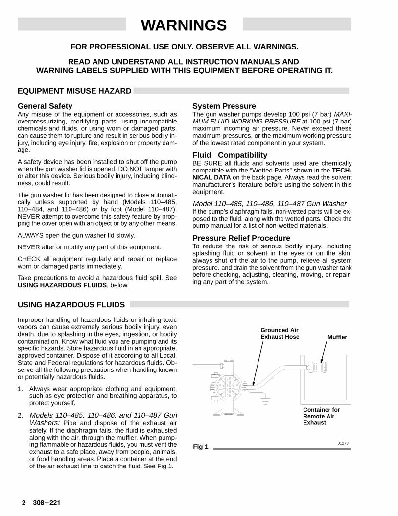
2. Models 110–485, 110–486, and 110–487 GunWashers: Pipe and dispose of the exhaust airsafely. If the diaphragm fails, the fluid is exhaustedalong with the air, through the muffler. When pump-ing flammable or hazardous fluids, you must vent theexhaust to a safe place, away from people, animals,or food handling areas. Place a container at the endof the air exhaust line to catch the fluid. See Fig 1.
Fig 1 01273
Grounded AirExhaust Hose Muffler
Container forRemote AirExhaust

�������� � � � �
FIRE OR EXPLOSION HAZARD
Flammable LiquidFlammable liquid solvent vapors may ignite. ALWAYSkeep all ignition sources such as static electricity, sparks,arcs, open flames (including pilot lights), and hot objects(including cigarettes) away from the gun washer and sol-vent.
MAKE SURE the ES ON-OFF valve lever (electrostatics)is “OFF” before cleaning an electrostatic gun.
NEVER allow solvent to enter the air passage of anyelectrostatic gun. Plug the gun air inlet before cleaningthe gun.
Use only solvents recommended by spray gun manufac-turer.
ALWAYS use solvent with the highest possible flash-point.
Use only non-conductive solvent when cleaning electros-tatic guns.
The PRO-Wash gun washer is classified as a temporarystorage container. To reduce the risk of fire or explosion,BE SURE to drain the solvent into a proper storage con-tainer and store it according to the local code for flam-mable liquids when shutting down your system.
Static SparkingStatic electricity is created by the fluid flowing through thepump and hose. If the equipment is not properlygrounded, sparking may occur, and the system maybecome hazardous. Sparks can ignite fumes from sol-
vents and the fluid being pumped, dust particles andother flammable substances, whether you are pumpingindoors or outdoors, and cause a fire or explosion, seri-ous bodily injury, and property damage.
If you experience any static sparking or even a slightshock while using this equipment, STOP USING THEEQUIPMENT IMMEDIATELY. Do not use the equipmentagain until the cause of the problem is identified and cor-rected.
GroundingTo reduce the risk of static sparking, ground the pumpand all other equipment used or located in the gun wash-er area. CHECK your local electrical code for detailedgrounding instructions for your area and type of equip-ment. GROUND ALL OF THIS EQUIPMENT.
1. Gun Washer: Ground as instructed on page 45
2. Air and Fluid hoses: Use only grounded hoses witha maximum of 500 ft. (150 m) combined hose lengthto ensure grounding continuity.
3. Air compressor: Ground according to manufactur-er’s recommendations.
4. Ground all solvent pails used when flushing anddraining according to local code. Use only metalpails, which are conductive. Do not place the pail ona non-conductive surface, such as paper or card-board, which interrupts the grounding continuity.
5. Fluid supply container: Ground according to localcode.
IMPORTANTUnited States Government safety standards have been adopted under the Occupational Safety and Health Act. Thesestandards – particularly the General Standards, Part 1910, Sections 1910.106 and 1910.107 – should be consulted.
CONTENTS
Warnings 2. . . . . . . . . . . . . . . . . . . . . . . . . . . . . . . . . . . . .
Installation 4. . . . . . . . . . . . . . . . . . . . . . . . . . . . . . . . . . .
Start-Up 7. . . . . . . . . . . . . . . . . . . . . . . . . . . . . . . . . . . . . .
Operation 8. . . . . . . . . . . . . . . . . . . . . . . . . . . . . . . . . . . . .
Shutdown and Care 11. . . . . . . . . . . . . . . . . . . . . . . . . .
Parts Drawings and Lists
Model 110–484 14. . . . . . . . . . . . . . . . . . . . . . . . . . . .
Model 110–485 16. . . . . . . . . . . . . . . . . . . . . . . . . . . .
Model 110–486 18. . . . . . . . . . . . . . . . . . . . . . . . . . . .
Model 110–487 20. . . . . . . . . . . . . . . . . . . . . . . . . . . .
Technical Data 23. . . . . . . . . . . . . . . . . . . . . . . . . . . . . . .
Warranty Back Cover. . . . . . . . . . . . . . . . . . . . . . . . . . . .
Important Phone Numbers Back Cover. . . . . . . . . . . .
�� � � � �������
INSTALLATION
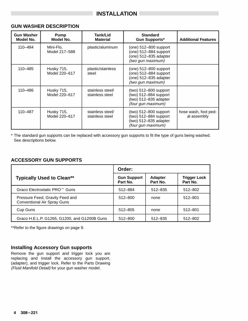
GUN WASHER DESCRIPTION
Gun WasherModel No.
Pump Model No.
Tank/LidMaterial
StandardGun Supports* Additional Features
110–484 Mini-Flo, Model 217–588
plastic/aluminum (one) 512–800 support(one) 512–884 support(one) 512–835 adapter(two gun maximum)
110–485 Husky 715, Model 220–617
plastic/stainlesssteel
(one) 512–800 support(one) 512–884 support(one) 512–835 adapter(two gun maximum)
110–486 Husky 715,Model 220–617
stainless steel/stainless steel
(two) 512–800 support(two) 512–884 support(two) 512–835 adapter(four gun maximum)
110–487 Husky 715,Model 220–617
stainless steel/stainless steel
(two) 512–800 support(two) 512–884 support(two) 512–835 adapter(four gun maximum)
hose wash, foot ped-al assembly
* The standard gun supports can be replaced with accessory gun supports to fit the type of guns being washed.See descriptions below.
ACCESSORY GUN SUPPORTS
Order:
Typically Used to Clean** Gun SupportPart No.
Adapter Part No.
Trigge r Lock Part No.
Graco Electrostatic PRO� Guns 512–884 512–835 512–802
Pressure Feed, Gravity Feed and Conventional Air Spray Guns
512–800 none 512–801
Cup Guns 512–805 none 512–801
Graco H.E.L.P. G1265, G1200, and G1200B Guns 512–800 512–835 512–802
**Refer to the figure drawings on page 9.
Installing Accessory Gun supportsRemove the gun support and trigger lock you arereplacing and install the accessory gun support,(adapter), and trigger lock. Refer to the Parts Drawing(Fluid Manifold Detail) for your gun washer model.

�������� � � � �
INSTALLATION
Install the Gun WasherWARNING
To prevent hazardous concentrations of toxic and/or flammable vapors, the gun washer must beinstalled in a properly ventilated paint mixing roomor spray booth. Never operate the gun washerunless ventilation fans are operating.
Check and follow all the National, State and Localcodes regarding ventilation requirements.
NOTE: Make sure the gun washer is standing on a level,solid surface.
Ground the Gun WasherWARNING
Static electricity is created by fluid flowing throughthe pump and hose. To reduce the risk of staticsparking, ground the pump and all other equipmentused or located in the gun washer area. Read FIREOR EXPLOSION HAZARD on page 2. Ground thegun washer as instructed below.
Ground the gun washer and its pump by connecting theclamp end of the gun washer’s 15 ft. (4.6 m) ground wireto a true earth ground. See Fig 2.
Fig 2 01274
Bleed-typeMaster
Air Valve
Air LineLubricator
GroundingClamp
Air Line
TYPICAL INSTALLA TION AND GROUNDING SHOWN

�� � � � �������
INSTALLATION
ALL MODELS1. Install a bleed-type master air valve upstream and
within easy reach of the gun washer to relieve airtrapped between this valve and the pump after the airis shut off. See Fig 2.
Continue with step 2 for your gun washer model.
WARNINGThe bleed-type master air valve is required in yoursystem to relieve air trapped between this valveand the pump after the air is shut off. Trapped aircan cause the pump to cycle unexpectedly, whichcould result in serious bodily injury, includingsplashing in the eyes or on the skin.
MODEL 110–4842. Model 110–484 includes a lubricator. See Fig 3. Fill
the lubricator reservoir to the “full line” with non-de-tergent SAE 30W oil. The lubricator adjustment knobhas been preset at the factory to provide the optimumdrip rate of five drops per minute of operation; do notreadjust.
3. Install into the end of the reset valve block a 1/4 in.npt male coupler that is compatible with the quick dis-connect of your air supply line.
4. Connect the air line to the coupler.
Fig 3 01277
Lubricator
ResetValveBlock
NeedleValveModel 110–484 1/4 npt(m)
Coupler
MODELS 110–485, 110–486, and 110–4872. Install an air line lubricator downstream of the master
air valve and as close to the pump as possible for au-tomatic air motor lubrication. See Fig 2.
3. Install into the air inlet adapter a 1/4 in. npt male cou-pler that is compatible with the quick disconnect ofyour air supply line. See Fig 4.
4. Connect the air line to the coupler.
Fig 4 01278
Model 110–485, 110–486, & 110–487
Air Filter/Regulator
DO NOTchangesetting
PilotValve
ResetValveBlock
1/4 npt(m)Coupler

�������� � � � �
START-UP
1. Apply � pipe paste to the fluid drain valve malethreads and screw it into the bottom of the gun wash-er. See Parts Drawing.
WARNINGImproper handling of hazardous fluids or inhalingtoxic vapors can cause extremely serious bodily in-jury, even death, due to splashing in the eyes,ingestion, or bodily contamination.
ALWAYS wear proper eye protection, breathing ap-paratus, and other appropriate clothing and equip-ment when operating or servicing this equipment.Consult the solvent’s Material Safety Data Sheetfor other precautionary requirements.
2. Make sure the fluid drain valve is in the closed posi-tion. Fill the gun washer fluid tank with solvent asinstructed for your gun washer model, below.
Models 110–485 and 110–484: Carefully pour sol-vent into the fluid tank until the fluid level is at least1/2 inch (12.7 mm) above the filter in the lower por-tion of the cabinet.
Models 110–486 and 110–487: Carefully pour sol-vent into the fluid tank until the fluid level is just belowthe bottom of the tank assembly.
NOTE: DO NOT pour more than 5 gallons (18.9 liters) ofa compatible solvent into the fluid tank.
CAUTIONUse only non-conductive solvents when cleaningelectrostatic guns. Conductive solvents can causethe gun to malfunction.
Follow the spray gun manufacturer’s cleaning rec-ommendations and the solvent material safetydata sheets when selecting a solvent.
WARNINGTo reduce the risk of fire or explosion, ALWAYSuse solvent with the highest possible flashpoint.
3. Set the air pressure to the pump between 40 and 75psi (2.8 and 5.2 bar).
4. Model 110–484: To adjust the pump, first close theair needle valve to the pump. Start the gun washer bydepressing the button on the reset valve block. SeeFig 3. Adjust the pump needle valve to achieve 120cycles/minute.
NOTE: Installing and using a regulator and filter will helpextend pump life.
Models 110–485, 110–486, and 110–487 include anair filter/regulator that has been preset at the factory;do not readjust it. See Fig 4.
CAUTIONDO NOT change the setting on the Husky pump’sair filter/regulator as this will damage the regulator.
PTFE

�� � � � �������
OPERATIONWARNING
Flammable liquid solvent vapors may ignite. Toreduce the risk of serious injury, explosion, or fire,ALWAYS keep all ignition sources such as staticelectricity, sparks, arcs, open flames (includingpilot lights), and hot objects (including cigarettes)away from the gun washer.
WARNINGTo avoid component rupture, which could result inserious injury or property damage, NEVER connectthe gun washer to a source of air pressure in ex-cess of 100 psi (7 bar) or above the maximum work-ing pressure of your lowest rated component.
NEVER operate the gun washer at a pressureabove the working pressure rating of the gun(s) be-ing cleaned.
Preparing Guns/Cups for the Gun Washer1. Remove the pressure cup or fluid line and the air line
from the spray gun.
2. Drain any excess fluid into a fluid container.
NOTE: The solvent in the gun washer will last longer ifpressure cups are thoroughly emptied beforeplacing them in the gun washer.
3. Remove the spray gun filter at the fluid inlet fitting.Clean spray gun filter daily or replace it if necessary.
4. Hang the gun on the gun holder rod on the front of thegun washer.
CAUTIONAll pressure gauges must be removed before plac-ing the painting equipment in the gun washer toavoid damaging the gauges.
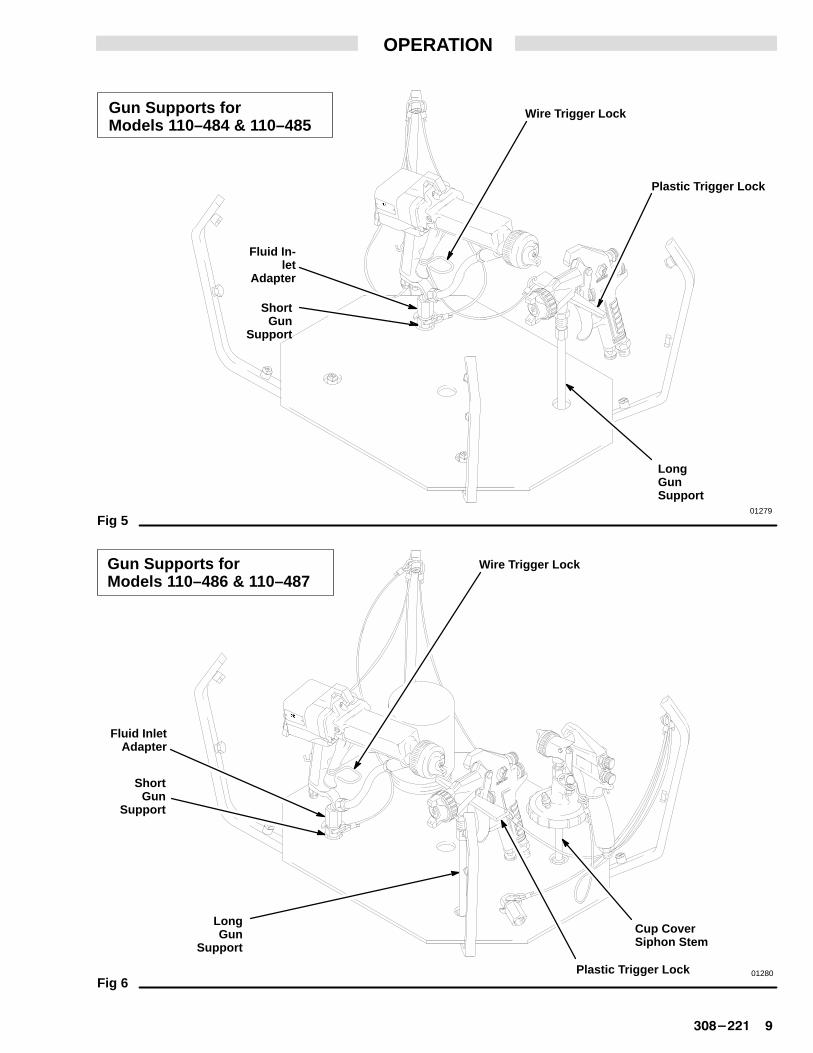
5. Electrostatic Guns: To lock the gun trigger in theopen position, install the wire trigger lock around thegun handle and trigger as shown in Fig 5 or 6.
H.E.L.P. G1265, G1200, G1200B Guns: To lock thegun trigger in the open position, install the wire triggerlock around the gun handle and trigger as shown inFig 6.
Other Guns: To lock the gun trigger in the open posi-tion, insert the narrow tip of the plastic trigger lockbetween the trigger and gun housing as shown in Fig5 or 6.
NOTE: If the plastic trigger lock cannot be inserted or thewire trigger lock does not fit on your electrostaticgun, wrap the chain around the trigger and han-dle to hold trigger in an open position.
Placing Guns/Cups in the Gun Washer
H.E.L.P. G1265, G1200, G1200B GunsScrew the fluid inlet adapter onto the H.E.L.P. gun fluidinlet. Set fluid inlet adapter over the long gun support.
Siphon Feed GunsSet the gun siphon stem over the short gun support.
Pressure Feed Guns with Cup (2 Qt. Capacity)Set the cup cover siphon stem over the short gun sup-port. Position the gun and hoses on the screen platform.See Fig 6.
Pressure Feed Guns (More Than 2 Qt. Capac-ity)Set the gun fluid inlet over the long gun support as shownin Fig 5 or 6.
Gravity Feed GunsSet the gun fluid inlet over the long gun support as shownin Fig 5 or 6.
Electrostatic GunsWARNING
To reduce the risk of electrostatic shock, fire, orexplosion; which could result in serious injury andproperty damage, be sure to follow these precau-tions.
� ONLY use non-conductive solvents whencleaning electrostatic guns.
� MAKE SURE the ES ON-OFF valve lever (elec-trostatics) is “OFF” before cleaning the gun.
� NEVER allow solvent to enter the air passageof any electrostatic gun. Plug the gun air inletbefore cleaning the gun.
� NEVER place the gun air inlet over a gunsupport.
� ONLY use the fluid inlet adapter provided withthe gun washer. Install it on the gun fluid inlet asinstructed below.
NOTE: The PRO-Wash� gun washer is approved toclean the Graco PRO 4000, PRO AA4000, PRO3500, and PRO 4500 electrostatic guns. Consultthe manufacturer of any other electrostatic gunbefore using the PRO-Wash.
1. MAKE SURE the ES ON-OFF lever (electrostatics)is OFF. Refer to your gun manual.
2. Screw the fluid inlet adapter onto the PRO-gun fluidinlet.
3. Place the gun in the gun washer, setting the fluid inletadapter over the short gun support as shown in Fig 5or 6.
Leave the air cap installed on the gun. Remove andclean it by hand after removing the gun from the gunwasher.
�������� � � � �
OPERATION
Fig 5
Gun Supports for Models 110–484 & 110–485
Gun Supports for Models 110–486 & 110–487
Fig 6
01279
01280
Wire Trigger Lock
Plastic T rigger Lock
Fluid In -let
Adapter
ShortGun
Support
LongGunSupport
Wire Trigger Lock
Plastic T rigger Lock
LongGun
Support
Fluid InletAdapter
ShortGun
Support
Cup Cover Siphon Stem

��� � � � �������
OPERATION
Model 110–487 -- Using the Hose Wash1. Place the hose entirely inside the gun washer.
2. Connect one end of the hose to the hose wash bulk-head fitting. See Fig 7.
3. Turn the hose/gun wash selector to HOSE WASH.
NOTE: When the selector is set for hose wash, the sol-vent is routed through the hose wash bulkheadfitting instead of the gun supports and spraynozzles.
4. Continue by following Operating the Gun Washerinstructions, at right.
Fig 7 01388
Model 110–487 -- Hose Wash
Hose/GunWash
Selector
Hose WashBulkheadFitting
Operating the Gun WasherWARNING
A safety device has been installed to shut off thepump when the gun washer lid is opened. DO NOTtamper with or alter this device. Serious bodily inju-ry, including blindness, could result.
ALWAYS open the gun washer lid slowly.
ALWAYS wear proper eye protection when operat-ing or servicing this equipment. Consult the solventMaterial Safety Data Sheet for other precautionaryrequirements.
The gun washer lid has been designed to close au-tomatically unless supported by hand (Models110–485, 110–484, and 110–486) or by foot (Model110–487). NEVER attempt to overcome this safetyfeature by propping the cover open with an object orby any other means.
1. Make sure all adaptor chains and cables are insidethe gun washer tank.
2. Close the gun washer lid.
3. Press the start button on the reset valve block to startthe gun washer. Guns, cups, or other paint utensilswill be cleaned, inside and out, in about 30 to 60 se-conds.
NOTE: Cleaning operation should not exceed 60seconds. Longer operation will not improve thecleaning process and will cause unnecessarywear on the pump.
If the lid is opened while the gun washer is operating,the air supply will automatically shut off and sprayingaction will stop. To restart the pump, close the lid andpress the start button.
4. If one or more of the gun mounts is not being used,place a stream blocking device, such as a pint-sizecan, over the stem supports and the cup spraynozzle not being used to prevent those jets of solventfrom hitting the underside of the gun washer lid.
WARNINGTo reduce the risk of fire or explosion, ALWAYSclean-up any solvent leaks or spills immediately.Repair any leaking components before operatingthe gun washer again.
Pump Operation and MaintenanceSee the pump instruction manual provided with the gunwasher for operation and maintenance of the pump.

�������� � � � ��
SHUTDOWN AND CARE
Gun Washer Shutdown and CareWARNING
When shutting down the gun washer and beforechecking, cleaning, adjusting, moving, or servicingit, ALWAYS disconnect the air supply, relieve pres-sure, and drain the solvent into a proper solventcontainer. This will reduce the risk of serious injury,including splashing in the eyes or on the skin, fire,explosion, or electric shock.
1. Drain the solvent from the gun washer tank daily.Place a proper solvent container under the fluid drainvalve on the bottom of the tank and open the fluiddrain valve.
WARNINGThe PRO-Wash gun washer is classified as a tem-porary storage container. To reduce the risk of fireor explosion, BE SURE to drain the solvent into aproper storage container and store it according tothe local code for flammable liquids when shuttingdown your system.
2. Wipe the inside of the tank with a cloth or use a brushto remove any built-up paint residue.
3. Thoroughly clean the gun washer filter (item 12 inParts Drawings) with a brush.
4. Change the solvent completely when it is no longerthoroughly cleaning the painting equipment. If thegun washer is being filled with old solvent, be sure tofilter the solvent before filling the gun washer tank.
NOTE: If the solvent is thoroughly filtered daily toremove paint residue, it can usually be reusedfor 2 to 8 weeks (depending on gun washerusage).
WARNINGTo reduce the risk of fire or explosion, ALWAYSclean-up any solvent leaks or spills immediately.Repair any leaking components before operatingthe gun washer again.
Air Cut-off Switch and Reset BlockWARNING
A safety device has been installed to shut off thepump when the gun washer lid is opened. DO NOTtamper with or alter this device. Serious bodily inju-ry, including blindness, could result.
The air connections between the air cut-off switch and re-set block are color coded. They must ALWAYS be con-nected as shown in Fig 8.
Fig 8 01281
Air Cut-off and Reset Block for Models 110–485, 110–486, & 110–487
Air Cut-off and Reset Block for Model 110–484
OILER
PUMP
top port
bot. port
Pilot SignalClear Color
Lid Closed Sig-nalBlue Color
Air SupplyBlack Color
Limit Switch
Pilot Signal
Pilot ValveMain AirMountingHardware
StartSwitch
Limit Switch
Lid Closed SignalBlue Color
Air SupplyBlack Color
PUMP OILER
StartSwitch
Main Air In

��� � � � �������
SERVICE
Check the Gun Washe r Electrical ContinuityWARNING
There must be electrical continuity between thegun washer’s fluid tank, divider plate, frame, andmain ground wire. To reduce the risk of static spark-ing, fire, or explosion, check the gun washer electri-cal continuity between all gun washer metallic partsand true earth ground before operating the gunwasher again, after servicing it.
Check your local electrical code for detailed groundinginstructions for your area and type of equipment.
If electrical continuity is lost, check the grounding con-nections and reconnect them as needed. See Fig 9 forthe gun washers grounding circuits.
Fig 9 01276
Grounding Circuit for Models 110–484 & 110–485
Grounding Circuit for Models 110–486 & 110–487
Jumper Wirefrom Lid to
Fluid Manifold
Jumper W ire fromFluid Drain V alve to
Pump Grounding Bar
Ground Wireto True Earth
Ground
Ground Wireto True Earth
Ground
Jumper W ire fromPump Outlet to
Pump Grounding Bar
Jumper W ire fromPump Inlet to
Pump Grounding Bar
MODEL 110–485 SHOWN

�������� � � � ��
NOTES
ÂÂÂÂÂÂ
23
13
2
125
6
10
16
27
Ref A
15
28
01282
Ref FluidManifold
Detail
26
7 30
��� � � � �������
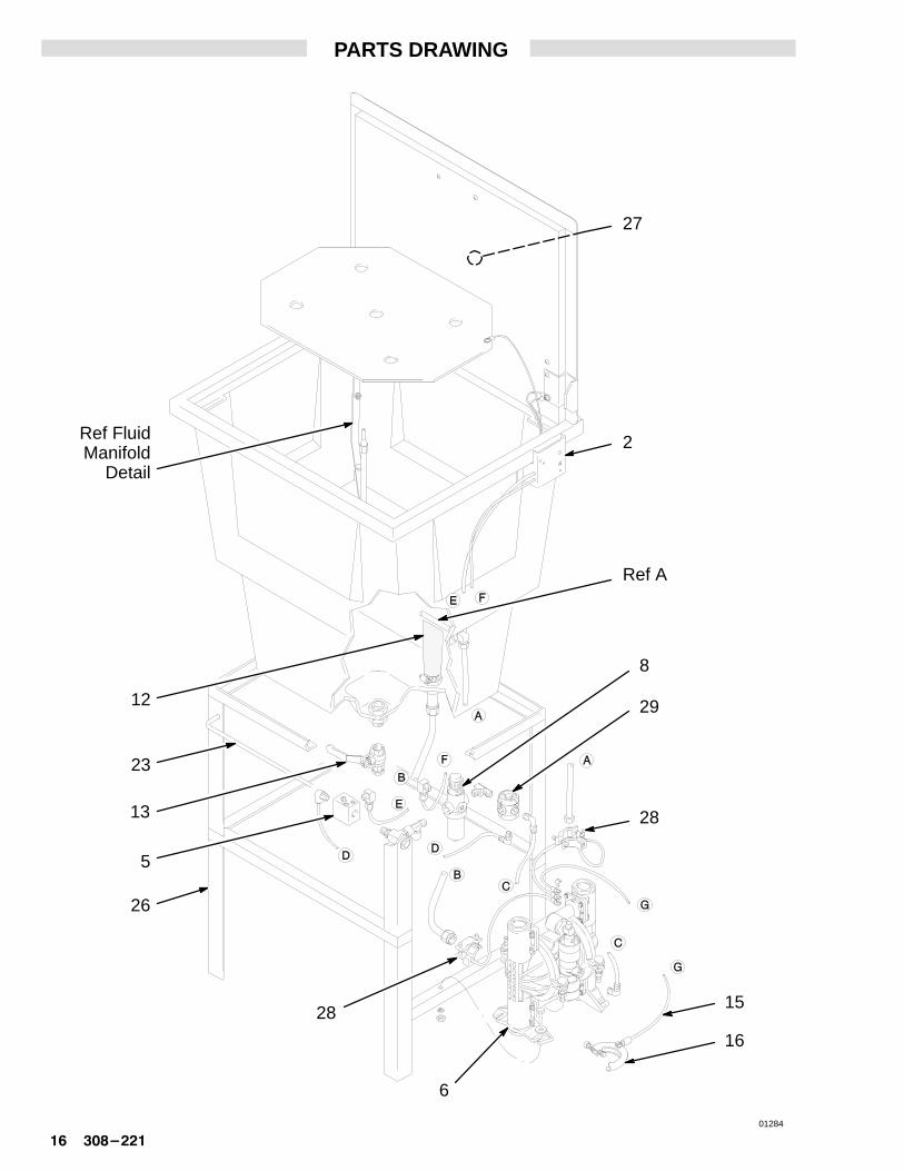
PARTS DRAWING

�������� � � � ��
PARTS LIST
Model 110–484 Gun Washer
REF NO. PART NO. DESCRIPTION QTY
1 512–799 NOZZLE, spray; brass 102 512–803 SWITCH, air cut-off 14 512–827 PLUG; brass 25 512–804 BLOCK, reset valve 16 512–826 OILER, air 17 512–837 MUFFLER, pump 110 222–590 PUMP, Mini-Flo; See manual
307–618 to order parts 111 512–807 TUBING, pump (lower);
tin-coated steel 112 513–290 FILTER, fluid 113 102–646 VALVE, fluid drain; brass 114 512–800 GUN SUPPORT, long; brass 115 512–871 WIRE, grounding 1
REF NO. PART NO. DESCRIPTION QTY
16 103–538 CLAMP, grounding 117 512–801 TRIGGER LOCK; plastic 118 512–884 GUN SUPPORT, short; brass 119 512–802 TRIGGER LOCK, wire;
stainless steel 121 512–835 ADAPTER, fluid inlet, PRO-gun;
brass 123 512–867 ROD, gun holder 126 110–559 STAND, gun washer 127* 186–527 LABEL, warning, gun washer 128 513–049 JUMPER, ground 130* 181–211 LABEL, warning, pump 1
*Warning labels available at no charge from Graco.
Fluid Manifold Detail
1
17
Ref A
19
4
14
21
18
01285
23
13
12
2
27
Ref A
5
15
16
29
8
6
28
28
01284
Ref FluidManifold
Detail
26
��� � � � �������
PARTS DRAWING

�������� � � � ��
PARTS LIST
Model 110–485 Gun Washer
REF NO. PART NO. DESCRIPTION QTY
1 512–799 NOZZLE, spray; brass 112 512–803 SWITCH, air cut-off 14 512–827 PLUG; brass 15 512–804 BLOCK, reset valve 16** 220–617 PUMP, Husky 715; See manual
307–855 to order parts 18 512–838 REGULATOR, air filter 112 513–290 FILTER, fluid 113 102–646 VALVE, fluid drain; brass 114 512–800 GUN SUPPORT, long; brass 115 512–871 WIRE, grounding 116 103–538 CLAMP, grounding 117 512–801 TRIGGER LOCK; plastic 118 512–884 GUN SUPPORT, short; brass 1
REF NO. PART NO. DESCRIPTION QTY
19 512–802 TRIGGER LOCK, wire;stainless steel 1
21 512–835 ADAPTER, fluid inlet, PRO-gun;brass 1
23 512–867 ROD, gun holder 126 110–566 STAND, gun washer 127* 186–527 LABEL, warning, gun washer 128 513–049 JUMPER, ground 229 104–633 VALVE, pilot 1
*Warning labels available at no charge from Graco.
** If a pump is ordered, the replacement pump’s manifoldmust be rotated before installing it on the gun washer.See manual 307–855.
Fluid Manifold Detail
1
17
Ref A
19
4
14
21
18
01285

Ref A2
5
68
12
13
15
16
27
28
29
01286
Ref FluidManifold
Detail
26
��� � � � �������
PARTS DRAWING

�������� � � � ��
PARTS LIST
Model 110–486 Gun Washer
REF NO. PART NO. DESCRIPTION QTY
1 512–799 NOZZLE, spray; brass 82 512–803 SWITCH, air cut-off 14 512–827 PLUG; brass 45 512–804 BLOCK, reset valve 16� 220–617 PUMP, Husky 715; See manual
307–855 to order parts 18 512–838 REGULATOR, air filter 112 513–290 FILTER, fluid 113 102–646 VALVE, fluid drain; brass 114 512–800 GUN SUPPORT, long; brass 215 512–871 WIRE grounding 116 103–538 CLAMP, grounding 117 512–801 TRIGGER LOCK; plastic 218 512–884 GUN SUPPORT, short; brass 2
REF NO. PART NO. DESCRIPTION QTY
19 512–802 TRIGGER LOCK, wire;stainless steel 2
21 512–835 ADAPTER, fluid inlet, PRO-gun;brass 2
26 110–567 STAND, gun washer 127* 186–527 LABEL, warning, gun washer 128 513–049 JUMPER, ground 129 104–633 VALVE, pilot 1
* Replacement Danger and Warning labels, tags andcards are available at no cost.
� When replacing a pump, the pump’s manifold mustbe rotated before installing it on the gun washer.Refer to manual 307–855.
Fluid Manifold Detail
1
17
Ref A
19
4
14
21
18
01287A

27
5
6
8
12
13
1516
24
28
31
32
33
39
29
2
Ref A
01288
23
37
Ref FluidManifold
Detail
26
��� � � � �������
PARTS DRAWING

�������� � � � ��
PARTS LIST
Model 110–487 Gun Washer
REF NO. PART NO. DESCRIPTION QTY
1 512–799 NOZZLE, spray; brass 82 512–803 SWITCH, air cut-off 14 512–827 PLUG; brass 45 512–804 BLOCK, reset valve 16� 220–617 PUMP, Husky 715; See manual
307–855 to order parts 18 512–838 REGULATOR, air filter 112 513–290 FILTER, fluid inlet 113 102–646 VALVE, fluid drain; brass 114 512–800 GUN SUPPORT, long; brass 215 512–871 WIRE, grounding 116 103–538 CLAMP, grounding 117 512–801 TRIGGER LOCK; plastic 218 512–884 GUN SUPPORT, short; brass 219 512–802 TRIGGER LOCK, wire;
stainless steel 221 512–835 ADAPTER, fluid inlet, PRO-gun
brass 2
REF NO. PART NO. DESCRIPTION QTY
23 513–284 GASKET, lid 124 512–868 SHOCK ABSORBER 126 110–568 STAND, gun washer 127* 186–527 LABEL, warning, gun washer 128 513–049 JUMPER, ground 229 104–633 VALVE, pilot 131 948–598 HOSE WASHING KIT 132 513–285 ROD, lid opener 133 513–292 ELBOW, inlet filter; stainless steel 137 513–305 ROD, trip 139 512–866 FOOT PEDAL ASSY. 1
* Replacement Danger and Warning labels, tags andcards are available at no cost.
� When replacing a pump, the pump’s manifold mustbe rotated before installing it on the gun washer.Refer to manual 307–855.
Fluid Manifold Detail
1
17
Ref A
19
4
14
21
18
01287A

��� � � � �������
NOTES

TECHNICAL DATA
Air Pressure Operating RangeModel 110–484 30–100 psi (2–7 bar). . . . . . . . . . . . Model 110–485 25–100 psi (1.7–7 bar). . . . . . . . . . Model 110–486 25–100 psi (1.7–7 bar). . . . . . . . . . Model 110–487 25–100 psi (1.7–7 bar). . . . . . . . . .
Maximum Tank Capacity 5 gal. (19 liters). . . . . . . . . . Air Inlet 1/4 npt(f). . . . . . . . . . . . . . . . . . . . . . . . . . . . . . . .
Approximate Dry WeightModel 110–484 69 lbs. (31.1 kg). . . . . . . . . . . . . . . . Model 110–485 76 lbs. (34.2 kg). . . . . . . . . . . . . . . . Model 110–486 86 lbs. (38.7 kg). . . . . . . . . . . . . . . . Model 110–487 90 lbs. (40.5 kg). . . . . . . . . . . . . . . .
Wetted PartsModel 110–484 Carbon Steel,. . . . . . . . . . . . . . . . . .
Polyethylene (tank), Aluminum, Zinc-platedSteel, Chrome-plated Steel, Stainless Steel,Brass, , Nylon,
Model 110–485 Carbon Steel,. . . . . . . . . . . . . . . . . . Polyethylene (tank), 303 Stainless Steel, Alumi-
num, Brass, , AcetalModel 110–486 Stainless Steel,. . . . . . . . . . . . . . . . .
Chrome-plated Carbon Steel, Aluminum, Brass,Acetal,
Model 110–487 Stainless Steel, Brass,. . . . . . . . . . Acetal,
MANUAL CHANGE SUMMARY
This manual was changed form Revision A to Revision Bto correct the Fluid Manifold configurations for Models110−486 and 110−487 (pages 19 & 21). In the TechnicalData section, Model numbers were inserted under“Wetted Parts.”
PTFE
PTFE
PTFE
PTFE

��� � � � �������
THE GRACO WARRANTY AND DISCLAIMERSWARRANTY
Graco warrants all equipment manufactured by it and bearing its name to be free from defects in material and workmanship onthe date of sale by an authorized Graco distributor to the original purchaser for use. As purchaser’s sole remedy for breach of thiswarranty, Graco will, for a period of twelve months from the date of sale, repair or replace any part of the equipment proven defec-tive. This warranty applies only when the equipment is installed, operated and maintained in accordance with Graco’s written rec-ommendations.
This warranty does not cover, and Graco shall not be liable for, any malfunction, damage or wear caused by faulty installation,misapplication, abrasion, corrosion, inadequate or improper maintenance, negligence, accident, tampering, or substitution ofnon–Graco component parts. Nor shall Graco be liable for malfunction, damage or wear caused by the incompatibility with Gracoequipment of structures, accessories, equipment or materials not supplied by Graco, or the improper design, manufacture, instal-lation, operation or maintenance of structures, accessories, equipment or materials not supplied by Graco.
This warranty is conditioned upon the prepaid return of the equipment claimed to be defective to an authorized Graco distributorfor verification of the claim. If the claimed defect is verified, Graco will repair or replace free of charge any defective parts. Theequipment will be returned to the original purchaser transportation prepaid. If inspection of the equipment does not disclose anydefect in material or workmanship, repairs will be made at a reasonable charge, which charges may include the costs of parts,labor and transportation.
DISCLAIMERS AND LIMITATIONS
The terms of this warranty constitute purchaser’s sole and exclusive remedy and are in lieu of any other warranties (express orimplied), including warranty of merchantability or warranty of fitness for a particular purpose , and of any non–contractualliabilities, including product liabilities, based on negligence or strict liability. Every form of liability for direct, special or consequen-tial damages or loss is expressly excluded and denied. In no case shall Graco’s liability exceed the amount of the purchase price.Any action for breach of warranty must be brought within two (2) years of the date of sale.
EQUIPMENT NOT COVERED BY GRACO WARRANTY
Graco makes no warranty, and disclaims all implied warranties of merchantability and fitness for a particular purpose , withrespect to accessories, equipment, materials, or components sold but not manufactured by Graco. These items sold, but notmanufactured by Graco (such as electric motor, switches, hose, etc.) are subject to the warranty, if any, of their manufacturer.Graco will provide purchaser with reasonable assistance in making any claim for breach of these warranties.
GRACO PHONE NUMBERS
TO PLACE AN ORDER, contact your Graco distrib-utor, or call this number to identify the distributorclosest to you: 1–800–367–4023 Toll Free
FOR TECHNICAL ASSISTANCE, service repairinformation or assistance regarding the application ofGraco equipment: 1–800–543–0339 Toll Free
Sales Offices: Atlanta, Chicago, Dallas, Detroit, Los Angeles, Mt. Arlington (N.J.)Foreign Offices: Canada; England; Korea; Switzerland; France; Germany; Hong Kong; Japan
GRACO INC. P.O. BOX 1441 MINNEAPOLIS, MN 55440–1441PRINTED IN U.S.A. 308−221 7/92 Revised 9/93