30015t5e, t5x, v7j 30022t5e, t5x, v6j, v8z, vrj
TRANSCRIPT
Published Manual Number/ECN: MQRMNM01U2/2017192A• Publishing System: TPAS2• Access date: 05/08/2017• Document ECNs: Latest
30015T5E, T5X, V7J30022T5E, T5X, V6J, V8Z,VRJ
PELLERIN MILNOR CORPORATION POST OFFICE BOX 400, KENNER, LOUISIANA 70063-0400, U.S.A.


MQRMNM01U2/17192A
1 1. English3 Maintenance Guide—30-series, Console style OPL
Washer-extractor MQRMNM01EN/20120626
33 2. Português35 Manutenção — Série 30, Lavadora Extratora OPL estilo
Console MQRMNM01PT/20120626
65 3. Nederlands67 Onderhoud—30-serie, OPL-was-/extractiemach ine in
consolestijl MQRMNM01NL/20120626


English 1
1


Published Manual Number: MQRMNM01EN • Specified Date: 20120626• As-of Date: 20120626• Access Date: 20120626• Depth: Detail• Custom: n/a• Applicability: RMN• Language Code: ENG01, Purpose: publication, Format: 1colA
Maintenance Guide— 30-series, Console style OPL Washer-extractor
PELLERIN MILNOR CORPORATION POST OFFICE BOX 400, KENNER, LOUISIANA 70063 - 0400, U.S.A.
3

Applicable Milnor® products by model number: 30015T5E 30015T5X 30015V7J 30022T5E 30022T5X 30022V6J 30022V8Z 30022VRJ
4

Table of Contents
PELLERIN MILNOR CORPORATION
Table of Contents Sections Figures, Tables, and Supplements
Chapter 1. Machine Description, Identification, and Certification
1.1. About This Milnor® Machine—30-series, Console style OPL Washer-extractor (Document BIUUUF01)
1.1.1. Functional Description 1.1.2. Machine Identification Figure 1: Machine Data Plate
1.2. General Content of the EC-Declaration of Conformity (Document BIWUUL01)
Chapter 2. Safety
2.1. Safety—Rigid Washer Extractors (Document BIUUUS27) 2.1.1. General Safety Requirements—Vital Information for
Management Personnel (Document BIUUUS04)
2.1.1.1. Laundry Facility 2.1.1.2. Personnel 2.1.1.3. Safety Devices 2.1.1.4. Hazard Information 2.1.1.5. Maintenance
2.1.2. Safety Alert Messages—Internal Electrical and Mechanical Hazards (Document BIUUUS11)
2.1.3. Safety Alert Messages—Cylinder and Processing Hazards (Document BIUUUS13)
2.1.4. Safety Alert Messages—Unsafe Conditions (Document BIUUUS14)
2.1.4.1. Damage and Malfunction Hazards 2.1.4.1.1. Hazards Resulting from Inoperative Safety
Devices
2.1.4.1.2. Hazards Resulting from Damaged Mechanical Devices
2.1.4.2. Careless Use Hazards 2.1.4.2.1. Careless Operation Hazards—Vital Information
for Operator Personnel (see also operator hazards throughout manual)
2.1.4.2.2. Careless Servicing Hazards—Vital Information for Service Personnel (see also service hazards throughout manuals)
2.2. Prevent Damage From Chemical Supplies and Chemical Systems (Document BIWUUI06)
2.2.1. How Chemical Supplies Can Cause Damage 2.2.1.1. Dangerous Chemical Supplies and Wash Formulas
5

Table of Contents
PELLERIN MILNOR CORPORATION
Sections Figures, Tables, and Supplements
2.2.1.2. Incorrect Configuration or Connection of Equipment Figure 2: Incorrect Configurations That Let the Chemical Supply Go In the Machine by a Siphon
Figure 3: Incorrect Configurations That Let the Chemical Supply Go In the Machine by Gravity
2.2.2. Equipment and Procedures That Can Prevent Damage 2.2.2.1. Use the Chemical Manifold Supplied. Figure 4: Examples of Manifolds for
Chemical Tubes. Your equipment can look different.
2.2.2.2. Close the line. 2.2.2.3. Do not let a vacuum occur. 2.2.2.4. Flush the chemical tube with water. 2.2.2.5. Put the chemical tube fully below the machine inlet. Figure 5: A Configuration that Prevents
Flow in the Machine When the Pump is Off (if the chemical tube and tank have no pressure)
2.2.2.6. Prevent leaks.
Chapter 3. Routine Maintenance
3.1. Routine Maintenance—30-series, Console style OPL Washer-extractor (Document BIUUUM09)
3.1.1. How To Show the Maintenance On a Calendar Table 1: Where to Put Marks On a Calendar
3.1.2. Maintenance Summary Table 2: Guards and Related Components Table 3: Filters, Screens, and Sensitive
Components Table 4: Fluid Containers Table 5: Components that Become Worn Table 6: Bearings and Bushings. See Table
7 for Motors. Table 7: Motor Grease Schedule. Use the
data in Section 3.1.4.2 to complete this table.
Table 8: Mechanisms and Settings 3.1.3. How to Remove Contamination Table 9: Contamination Types, Cleaning
Agents, and Procedures 3.1.4. Lubricant Identification and Procedures Table 10: Lubricant Identification
3.1.4.1. Grease Gun Procedures 3.1.4.2. Procedures for Motors Figure 6: Motor Grease Maintenance
Conditions Table 11: Motor Grease Intervals and
Quantities. Use grease EM (Table 10)
6

Table of Contents
PELLERIN MILNOR CORPORATION
Sections Figures, Tables, and Supplements
3.1.5. Maintenance Components—Machines and Controls Group (Document BIUUUM10)
Supplement 1: How to Examine Belts and Pulleys
Figure 7: Belt and Pulley Conditions To Look For. See Supplement 1.
Figure 8: Electric Box and Inverter. These are examples. Your machine can look different.
Figure 9: Chemical Inlet Manifolds for Chemical Pump Systems. See caution statement 24 . These are examples. Your machine can look different.
Figure 10: Soap Chute and Optional 3-compartment Supply Injector
Figure 11: Air Tube for the Water Level Sensor. These are examples. Your machine can look different.
Figure 12: Steam Inlet Strainer. These are examples. Your machine can look different.
Figure 13: Compressed Air Inlet Strainers. These are examples. Your machine can look different.
3.1.6. Maintenance Components—Large Extractors (Document BIWUUM03)
Figure 14: Oil Maintenance Areas for Bearing Assembly. A 30022T5E is shown. Your machine can look different.
7

Chapter 1. Machine Description, Identification, and Certification
PELLERIN MILNOR CORPORATION
Chapter 1 Machine Description, Identification, and Certification
BIUUUF01 (Published) Book specs- Dates: 20120501 / 20120501 / 20120501 Lang: ENG01 Applic: RMN 1.1. About This Milnor® Machine—30-series, Console style OPL
Washer-extractor This manual applies to the Milnor products whose model numbers are listed inside the front cover and which are in the families of machines defined below.
1.1.1. Functional Description Washer-extractors wash linen using water and nonvolatile chemicals and remove excess water by centrifugal force.
30-series, Console style OPL Washer-extractor models are rigid mount, visible shell washer-extractors, with a cylinder diameter of 30 inches (762 mm), for use in nursing homes, schools, and similar on-premise laundry applications.
1.1.2. Machine Identification Find the model number and other data for your machine on the machine data plate affixed to the machine. See the figure that follows.
8

Chapter 1. Machine Description, Identification, and Certification
PELLERIN MILNOR CORPORATION
Figure 1: Machine Data Plate
View of Data Plate (English text shown) Legend
.
1. Model number. See inside the front cover of this manual.
2. Data that uniquely identifies your machine
3. Cylinder maximum rotation speed in revolutions per minute, if applicable
4. Cylinder volume in the units of measure shown, if applicable
5. Piped utility requirements 6. Hydraulic oil pressure, if
applicable 7. Electrical requirements 8. Part number for
multi-unit machine, if applicable.
— End of BIUUUF01 —
BIWUUL01 (Published) Book specs- Dates: 20120501 / 20120501 / 20120501 Lang: ENG01 Applic: RMN 1.2. General Content of the EC-Declaration of Conformity
Manufacturer Pellerin Milnor Corporation
Hereby we declare under our sole responsibility that the machinery Type (see the declaration for your machine) Serial no (see the declaration for your machine) Manufacturing date (see the declaration for your machine)
is in conformity with the provisions of Machinery Directive (89/392 EEC) as amended.
Pellerin Milnor Corporation certifies that the machine(s) listed above, manufactured in Kenner, Louisiana, 70063, USA conform(s) as stipulated by schedule of verification of ISO/DIS 10 472-1 of June 1994 Safety Requirements for Industrial Laundry Machine, Part One, Common Requirements for All Types, ISO/DIS 10 472-2 of June 1994, Safety Requirements for Industrial Laundry Machine, Part Two: Washing Machines and Washer Extractors, BS EN 294 of 1992 Safety of Machinery, Safety Distances to Prevent Danger Zones Being Reached by the Upper Limbs, and EN 60204-1 of October 1992, Safety of Machinery, Electrical Equipment of Machines, Part One, General Requirements. EN50081-1,2 Electromagnetic Compatibility. Safety compliance to the standard is described in detail in MILNOR manual (see the declaration for your machine).
This letter confirms that the machine(s) only meets the required aforementioned standards. It is the responsibility of the installer/owner of the machine(s) to ensure compliance with all requirements for on-site preparation, installation, and operation.
Our conformance to the above listed standards is certified with exceptions listed in MILNOR Conformance Report (see the declaration for your machine).
Place Kenner, Louisiana, 70063, USA
9

Chapter 1. Machine Description, Identification, and Certification
PELLERIN MILNOR CORPORATION
Date of first issue of above mentioned machine type Signature Kenneth W. Gaulter Engineering Manager
Signature Russell H. Poy Vice President, Engineering
— End of BIWUUL01 —
10

Chapter 2. Safety
PELLERIN MILNOR CORPORATION
Chapter 2 Safety
BIUUUS27 (Published) Book specs- Dates: 20120501 / 20120501 / 20120501 Lang: ENG01 Applic: RMN 2.1. Safety—Rigid Washer Extractors
2.1.1. General Safety Requirements—Vital Information for Management Personnel [Document BIUUUS04] Incorrect installation, neglected preventive maintenance, abuse, and/or improper repairs, or changes to the machine can cause unsafe operation and personal injuries, such as multiple fractures, amputations, or death. The owner or his selected representative (owner/user) is responsible for understanding and ensuring the proper operation and maintenance of the machine. The owner/user must familiarize himself with the contents of all machine instruction manuals. The owner/user should direct any questions about these instructions to a Milnor® dealer or the Milnor® Service department.
Most regulatory authorities (including OSHA in the USA and CE in Europe) hold the owner/user ultimately responsible for maintaining a safe working environment. Therefore, the owner/user must do or ensure the following:
• recognize all foreseeable safety hazards within his facility and take actions to protect his personnel, equipment, and facility;
• work equipment is suitable, properly adapted, can be used without risks to health or safety, and is adequately maintained;
• where specific hazards are likely to be involved, access to the equipment is restricted to those employees given the task of using it;
• only specifically designated workers carry out repairs, modifications, maintenance, or servicing;
• information, instruction, and training is provided; • workers and/or their representatives are consulted.
Work equipment must comply with the requirements listed below. The owner/user must verify that installation and maintenance of equipment is performed in such a way as to support these requirements:
• control devices must be visible, identifiable, and marked; be located outside dangerous zones; and not give rise to a hazard due to unintentional operation;
• control systems must be safe and breakdown/damage must not result in danger; • work equipment is to be stabilized; • protection against rupture or disintegration of work equipment;
11

Chapter 2. Safety
PELLERIN MILNOR CORPORATION
• guarding, to prevent access to danger zones or to stop movements of dangerous parts before the danger zones are reached. Guards to be robust; not give rise to any additional hazards; not be easily removed or rendered inoperative; situated at a sufficient distance from the danger zone; not restrict view of operating cycle; allow fitting, replacing, or maintenance by restricting access to relevant area and without removal of guard/protection device;
• suitable lighting for working and maintenance areas; • maintenance to be possible when work equipment is shut down. If not possible, then
protection measures to be carried out outside danger zones; • work equipment must be appropriate for preventing the risk of fire or overheating; discharges
of gas, dust, liquid, vapor, other substances; explosion of the equipment or substances in it.
2.1.1.1. Laundry Facility—Provide a supporting floor that is strong and rigid enough to support–with a reasonable safety factor and without undue or objectionable deflection–the weight of the fully loaded machine and the forces transmitted by it during operation. Provide sufficient clearance for machine movement. Provide any safety guards, fences, restraints, devices, and verbal and/or posted restrictions necessary to prevent personnel, machines, or other moving machinery from accessing the machine or its path. Provide adequate ventilation to carry away heat and vapors. Ensure service connections to installed machines meet local and national safety standards, especially regarding the electrical disconnect (see the National Electric Code). Prominently post safety information, including signs showing the source of electrical disconnect.
2.1.1.2. Personnel—Inform personnel about hazard avoidance and the importance of care and common sense. Provide personnel with the safety and operating instructions that apply to them. Verify that personnel use proper safety and operating procedures. Verify that personnel understand and abide by the warnings on the machine and precautions in the instruction manuals.
2.1.1.3. Safety Devices—Ensure that no one eliminates or disables any safety device on the machine or in the facility. Do not allow machine to be used with any missing guard, cover, panel or door. Service any failing or malfunctioning device before operating the machine.
2.1.1.4. Hazard Information—Important information on hazards is provided on the machine safety placards, in the Safety Guide, and throughout the other machine manuals. Placards must be kept clean so that the information is not obscured. They must be replaced immediately if lost or damaged. The Safety Guide and other machine manuals must be available at all times to the appropriate personnel. See the machine service manual for safety placard part numbers. Contact the Milnor Parts department for replacement placards or manuals.
2.1.1.5. Maintenance—Ensure the machine is inspected and serviced in accordance with the norms of good practice and with the preventive maintenance schedule. Replace belts, pulleys, brake shoes/disks, clutch plates/tires, rollers, seals, alignment guides, etc. before they are severely worn. Immediately investigate any evidence of impending failure and make needed repairs (e.g., cylinder, shell, or frame cracks; drive components such as motors, gear boxes, bearings, etc., whining, grinding, smoking, or becoming abnormally hot; bending or cracking of cylinder, shell, frame, etc.; leaking seals, hoses, valves, etc.) Do not permit service or maintenance by unqualified personnel.
12

Chapter 2. Safety
PELLERIN MILNOR CORPORATION
2.1.2. Safety Alert Messages—Internal Electrical and Mechanical Hazards [Document BIUUUS11] The following are instructions about hazards inside the machine and in electrical enclosures.
WARNING 1 : Electrocution and Electrical Burn Hazards—Contact with electric power can kill or seriously injure you. Electric power is present inside the cabinetry unless the main machine power disconnect is off. • Do not unlock or open electric box doors. • Do not remove guards, covers, or panels. • Do not reach into the machine housing or frame. • Keep yourself and others off of machine. • Know the location of the main machine disconnect and use it in an emergency to remove
all electric power from the machine.
WARNING 2 : Entangle and Crush Hazards—Contact with moving components normally isolated by guards, covers, and panels, can entangle and crush your limbs. These components move automatically. • Do not remove guards, covers, or panels. • Do not reach into the machine housing or frame. • Keep yourself and others off of machine. • Know the location of all emergency stop switches, pull cords, and/or kick plates and use
them in an emergency to stop machine motion.
2.1.3. Safety Alert Messages—Cylinder and Processing Hazards [Document BIUUUS13] The following are instructions about hazards related to the cylinder and laundering process.
DANGER 3 : Entangle and Sever Hazards—Contact with goods being processed can cause the goods to wrap around your body or limbs and dismember you. The goods are normally isolated by the locked cylinder door. • Do not attempt to open the door or reach into the cylinder until the cylinder is stopped. • Do not touch goods inside or hanging partially outside the turning cylinder. • Do not operate the machine with a malfunctioning door interlock. • Know the location of all emergency stop switches, pull cords, and/or kick plates and use
them in an emergency to stop machine motion. • Know the location of the main machine disconnect and use it in an emergency to remove
all electric power from the machine.
WARNING 4 : Crush Hazards—Contact with the turning cylinder can crush your limbs. The cylinder will repel any object you try to stop it with, possibly causing the object to strike or stab you. The turning cylinder is normally isolated by the locked cylinder door. • Do not attempt to open the door or reach into the cylinder until the cylinder is stopped. • Do not place any object in the turning cylinder. • Do not operate the machine with a malfunctioning door interlock.
WARNING 5 : Confined Space Hazards—Confinement in the cylinder can kill or injure you. Hazards include but are not limited to panic, burns, poisoning, suffocation, heat prostration, biological contamination, electrocution, and crushing.
13

Chapter 2. Safety
PELLERIN MILNOR CORPORATION
• Do not attempt unauthorized servicing, repairs, or modification.
WARNING 6 : Explosion and Fire Hazards—Flammable substances can explode or ignite in the cylinder, drain trough, or sewer. The machine is designed for washing with water, not any other solvent. Processing can cause solvent-containing goods to give off flammable vapors. • Do not use flammable solvents in processing. • Do not process goods containing flammable substances. Consult with your local fire
department/public safety office and all insurance providers.
2.1.4. Safety Alert Messages—Unsafe Conditions [Document BIUUUS14]
2.1.4.1. Damage and Malfunction Hazards
2.1.4.1.1. Hazards Resulting from Inoperative Safety Devices
DANGER 7 : Entangle and Sever Hazards—Cylinder door interlock—Operating the machine with a malfunctioning door interlock can permit opening the door when the cylinder is turning and/or starting the cycle with the door open, exposing the turning cylinder. • Do not operate the machine with any evidence of damage or malfunction.
WARNING 8 : Multiple Hazards—Operating the machine with an inoperative safety device can kill or injure personnel, damage or destroy the machine, damage property, and/or void the warranty. • Do not tamper with or disable any safety device or operate the machine with a
malfunctioning safety device. Request authorized service.
WARNING 9 : Electrocution and Electrical Burn Hazards—Electric box doors—Operating the machine with any electric box door unlocked can expose high voltage conductors inside the box. • Do not unlock or open electric box doors.
WARNING 10 : Entangle and Crush Hazards—Guards, covers, and panels—Operating the machine with any guard, cover, or panel removed exposes moving components. • Do not remove guards, covers, or panels.
2.1.4.1.2. Hazards Resulting from Damaged Mechanical Devices
WARNING 11 : Multiple Hazards—Operating a damaged machine can kill or injure personnel, further damage or destroy the machine, damage property, and/or void the warranty. • Do not operate a damaged or malfunctioning machine. Request authorized service.
WARNING 12 : Explosion Hazards—Cylinder—A damaged cylinder can rip apart during extraction, puncturing the shell and discharging metal fragments at high speed. • Do not operate the machine with any evidence of damage or malfunction.
14

Chapter 2. Safety
PELLERIN MILNOR CORPORATION
2.1.4.2. Careless Use Hazards
2.1.4.2.1. Careless Operation Hazards—Vital Information for Operator Personnel (see also operator hazards throughout manual)
WARNING 13 : Multiple Hazards—Careless operator actions can kill or injure personnel, damage or destroy the machine, damage property, and/or void the warranty. • Do not tamper with or disable any safety device or operate the machine with a
malfunctioning safety device. Request authorized service. • Do not operate a damaged or malfunctioning machine. Request authorized service. • Do not attempt unauthorized servicing, repairs, or modification. • Do not use the machine in any manner contrary to the factory instructions. • Use the machine only for its customary and intended purpose. • Understand the consequences of operating manually.
2.1.4.2.2. Careless Servicing Hazards—Vital Information for Service Personnel (see also service hazards throughout manuals)
WARNING 14 : Electrocution and Electrical Burn Hazards—Contact with electric power can kill or seriously injure you. Electric power is present inside the cabinetry unless the main machine power disconnect is off. • Do not service the machine unless qualified and authorized. You must clearly understand
the hazards and how to avoid them. • Abide by the current OSHA lockout/tagout standard when lockout/tagout is called for in
the service instructions. Outside the USA, abide by the OSHA standard in the absence of any other overriding standard.
WARNING 15 : Entangle and Crush Hazards—Contact with moving components normally isolated by guards, covers, and panels, can entangle and crush your limbs. These components move automatically. • Do not service the machine unless qualified and authorized. You must clearly understand
the hazards and how to avoid them. • Abide by the current OSHA lockout/tagout standard when lockout/tagout is called for in
the service instructions. Outside the USA, abide by the OSHA standard in the absence of any other overriding standard.
WARNING 16 : Confined Space Hazards—Confinement in the cylinder can kill or injure you. Hazards include but are not limited to panic, burns, poisoning, suffocation, heat prostration, biological contamination, electrocution, and crushing. • Do not enter the cylinder until it has been thoroughly purged, flushed, drained, cooled,
and immobilized. — End of BIUUUS27 —
BIWUUI06 (Published) Book specs- Dates: 20120501 / 20120501 / 20120501 Lang: ENG01 Applic: RMN 2.2. Prevent Damage From Chemical Supplies and Chemical
Systems
This document uses Simplified Technical English. Learn more at http://www.asd-ste100.org.
15

Chapter 2. Safety
PELLERIN MILNOR CORPORATION
All Milnor® washer-extractors and CBW® tunnel washers use stainless steel with the AISI 304 specification. This material gives good performance when chemical supplies are correctly applied. If chemical supplies are incorrectly applied, this material can be damaged. The damage can be very bad and it can occur quickly.
Chemical supply companies usually: • supply chemical pump systems that put the supplies in the machine, • connect the chemical pump system to the machine, • write wash formulas that control the chemical concentrations.
The company that does these procedures must make sure that these procedures do not cause damage. Pellerin Milnor Corporation accepts no responsibility for chemical damage to the machines it makes or to the goods in a machine.
2.2.1. How Chemical Supplies Can Cause Damage
2.2.1.1. Dangerous Chemical Supplies and Wash Formulas—Some examples that can cause damage are:
• a very high concentration of chlorine bleach, • a mixture of acid sour and hypo chlorite, • chemical supplies (examples: chlorine bleach, hydrofluosilicic acid) that stay on the stainless
steel because they are not quickly flushed with water.
The book “Textile Laundering Technology” by Charles L. Riggs gives data about correct chemical supplies and formulas.
2.2.1.2. Incorrect Configuration or Connection of Equipment—Many chemical systems: • do not prevent a vacuum in the chemical tube (for example, with a vacuum breaker) when the
pump is off, • do not prevent flow (for example, with a valve) where the chemical tube goes in the machine.
Damage will occur if a chemical supply can go in the machine when the chemical system is off. Some configurations of components can let the chemical supplies go in the machine by a siphon (Figure 2). Some can let chemical supplies go in the machine by gravity (Figure 3).
16

Chapter 2. Safety
PELLERIN MILNOR CORPORATION
Figure 2: Incorrect Configurations That Let the Chemical Supply Go In the Machine by a Siphon
Schematic Views
Legend
P. Pump T. Chemical tank S. The siphon occurs above here. Liquid in the gray parts of the chemical tube and tank can go in
the machine. .
17

Chapter 2. Safety
PELLERIN MILNOR CORPORATION
Figure 3: Incorrect Configurations That Let the Chemical Supply Go In the Machine by Gravity
Schematic Views
Legend
P. Pump T. Chemical tank D. Chemical tube. Liquid in the gray areas can go in the machine.
.
2.2.2. Equipment and Procedures That Can Prevent Damage
2.2.2.1. Use the Chemical Manifold Supplied.—There is a manifold on the machine to attach chemical tubes from a chemical pump system. Figure 3 shows examples. The manifold has a source of water to flush the chemical supplies with water. Figure 4: Examples of Manifolds for Chemical Tubes. Your equipment can look different.
18

Chapter 2. Safety
PELLERIN MILNOR CORPORATION
2.2.2.2. Close the line.—If the pump does not always close the line when it is off, use a shutoff valve to do this.
2.2.2.3. Do not let a vacuum occur.—Supply a vacuum breaker in the chemical line that is higher than the full level of the tank.
2.2.2.4. Flush the chemical tube with water.—If the liquid that stays in the tube between the pump and the machine can flow in the machine, flush the tube with water after the pump stops.
2.2.2.5. Put the chemical tube fully below the machine inlet.—It is also necessary that there is no pressure in the chemical tube or tank when the system is off. Figure 5 shows this configuration.
Figure 5: A Configuration that Prevents Flow in the Machine When the Pump is Off (if the chemical tube and tank have no pressure)
Schematic View Legend
.
I. Chemical inlet on the machine
L. Chemical tube P. Pump T. Chemical tank
2.2.2.6. Prevent leaks.—When you do maintenance on the chemical pump system: • Use the correct components. • Make sure that all connections are the correct fit. • Make sure that all connections are tight.
— End of BIWUUI06 —
19

Chapter 3. Routine Maintenance
PELLERIN MILNOR CORPORATION
Chapter 3 Routine Maintenance
BIUUUM09 (Published) Book specs- Dates: 20120501 / 20120501 / 20120501 Lang: ENG01 Applic: RMN 3.1. Routine Maintenance—30-series, Console style OPL
Washer-extractor
This document uses Simplified Technical English. Learn more at http://www.asd-ste100.org. Do the maintenance in Section 3.1.2 “Maintenance Summary” to make sure that the machine is safe, keeps the warranty, and operates correctly. This will also decrease repair work and unwanted shutdowns. Speak to your dealer or Milnor if repairs are necessary.
WARNING 19 : Risk of severe injury—Mechanisms can pull in and mutilate your body. • You must be approved by your employer for this work. • Use extreme care when you must examine components in operation. Remove power from
the machine for all other work. Obey safety codes. In the USA, this is the OSHA lockout/tagout (LOTO) procedure. More local requirements can also apply.
• Replace guards and covers that you remove for maintenance.
3.1.1. How To Show the Maintenance On a Calendar If you use software to keep the maintenance schedule for your plant, add the items in Section 3.1.2 to that schedule. If not, you can put marks on a calendar that work with the tables in Section 3.1.2. The marks are the numbers 2, 3, 4, 5, and 6. It is not necessary to show the number 1 (items you do each day) on the calendar. The number 2 = items you do each 40 to 60 hours, 3 = each 200 hours, 4 = each 600 hours, 5 = each 1200 hours, and 6 = each 2400 hours. These are the "Mark" numbers at the top of the narrow columns on the left of each table in Section 3.1.2.
Table 1 shows where to put the marks on a calendar. For example, if your machine operates between 41 and 60 hours each week, the first three marks are 2, 2, and 3. Put these marks on the first, second, and third weeks after the machine starts operation. If you do routine maintenance on a given day of the week, put the mark on that day of each week. Continue to put marks on the subsequent weeks. It can be necessary to do the 40 to 60 hour (2) maintenance more than one time each week. If the machine operates between 61 and 100 hours, put a 2 on two days of the week. If the machine operates 101 or more hours, put a 2 on three days of the week.
On each date with a 3, do the items with an x in the 3 or the 2 column of each table in Section 3.1.2. On each date with a 4, do the items with an x in the 4, 3, or 2 column. Continue this pattern.
20

Chapter 3. Routine Maintenance
PELLERIN MILNOR CORPORATION
Table 1: Where to Put Marks On a Calendar Week Number Hours /
Week 1 2 3 4 5 6 7 8 9 10 11 12 13 14 15 16 17 18 19 20 21 22 23 24 25 26 27 28 29 30 Up to 40 2 2 2 2 3 2 2 2 2 3 2 2 2 2 4 2 2 2 2 3 2 2 2 2 3 2 2 2 2 5 41 - 60 2 2 3 2 2 2 3 2 2 4 2 2 3 2 2 2 3 2 2 5 2 2 3 2 2 2 3 2 2 4 61 - 80 2 2 3 2 3 2 4 2 2 3 2 2 3 2 5 2 3 2 2 3 2 4 2 2 3 2 2 3 2 6 81 - 100 2 3 2 3 2 4 2 3 2 3 2 5 2 3 2 3 2 4 2 3 2 3 2 6 repeat 101 - 120 2 3 2 3 4 2 3 2 3 5 2 3 2 3 4 2 3 2 3 6 repeat 121 - 140 2 3 2 3 4 3 2 3 5 2 3 2 3 4 3 2 3 6 repeat
Week Number, continued Hours / Week 31 32 33 34 35 36 37 38 39 40 41 42 43 44 45 46 47 48 49 50 51 52 53 54 55 56 57 58 59 60 Up to 40 2 2 2 2 3 2 2 2 2 3 2 2 2 2 4 2 2 2 2 3 2 2 2 2 3 2 2 2 2 6 41 - 60 2 2 3 2 2 2 3 2 2 6 repeat
3.1.2. Maintenance Summary The tables in this section give the routine maintenance items for your machine. Each table is for one type of procedure (example: apply grease to bearings and bushings). The top of the table gives the general procedure. The "More Data" column gives special instructions if necessary.
* If the machine operates more than 12 hours each day, do the "day" items two times each day. Do the other items at the given hours or on the days that you show on a calendar (see Section 1). Do all items in all tables for the maintenance intervals that apply (for example, day, 40 to 60 hours, and 200 hours).
Tip: The sections that follow the maintenance summary give more data about the maintenance items. After you know this data, it is only necessary to look at the summary to do the maintenance.
Table 2: Guards and Related Components
Examine. If a component is damaged, missing, or not set, correct this immediately to prevent injury. Mark
1 2 3 4 5 6 Do this each Component More Data
x day* guards, covers x day* safety placards
Speak to your dealer or Milnor for replacement components.
x 200 hours fasteners Fasteners must be tight. x 200 hours anchor bolts and grout Grout must be good. Bolts must be tight. x day* door interlock If the machine operates with the door open:
Immediately remove power. Do not permit operation. Speak to your dealer or Milnor.
21

Chapter 3. Routine Maintenance
PELLERIN MILNOR CORPORATION
Table 3: Filters, Screens, and Sensitive Components
Remove contamination from these components to prevent damage and unsatisfactory performance. Mark
1 2 3 4 5 6 Do this each Component
More Data. See also Section 3.1.3 “How to Remove Contamination”
x 40 to 60 hours inverter fans, vents, filters See Figure 8. Keep good air flow. x 600 hours motors Keep good air flow. x 2400 hours entire machine Remove excessive dust and dirt. x day* chemical inlet areas Some chemical supplies that stay on machine
surfaces will cause corrosion damage. See Figure 9 and Section 2.2. “Prevent Damage From Chemical Supplies and Chemical Systems”
x 2400 hours water inlet strainers if supplied by others
Remove strainers from incoming water lines and flush with water.
x 2400 hours strainer in connector for each valve in 3-compartment supply injector
See Figure 10
x 200 hours strainer(s) for air inlet See Figure 13 x 200 hours strainer for steam inlet.
(Steam is optional on some models.)
See Figure 12
Table 4: Fluid Containers
Examine. Add fluid if necessary and keep components clean to prevent damage. Mark
1 2 3 4 5 6 Do this each Component
More Data. See also Section 3.1.4 “Lubricant Identification and Procedures”
x 600 hours bearing housing remove used oil. Add 22 ounces (650 ml) of oil 30 (Table 10). See Figure 14
Table 5: Components that Become Worn
Examine. Tighten or replace if necessary, to prevent shutdowns and unsatisfactory performance. Speak to your dealer for replacement parts
Mark 1 2 3 4 5 6
Do this each Component More Data
x 200 hours drive belts and pulleys See Supplement 1 and Figure 7 x 200 hours tubes and hoses Examine hoses and hose connections for
leaks.
22

Chapter 3. Routine Maintenance
PELLERIN MILNOR CORPORATION
Table 6: Bearings and Bushings. See Table 7 for Motors.
Apply grease to these components to prevent damage. Mark
1 2 3 4 5 6 Do this each Component
More Data. See also Section 3.1.4 “Lubricant Identification and Procedures”
x 600 hours bearing housing The bearing assembly is oil-filled. No routine grease maintenance is required. Grease is added to the seal grease cavity at assembly. Examine the grease cavity drain tube (Figure 14). If a large quantity of contamination or water flows from the tube, maintenance can be necessary. Speak to your dealer or Milnor.This is not routine maintenance.
Table 7: Motor Grease Schedule. Use the data in Section 3.1.4.2 to complete this table.
Interval Quantity Dates When Grease is Added Motor Identification (example: main drive) Years Hours fl oz mL . Table 8: Mechanisms and Settings
Make sure mechanisms are serviceable and settings are correct to prevent unsatisfactory performance.
Mark 1 2 3 4 5 6
Do this each Component More Data
x 2400 hours controller circuitry Examine wiring and connections in electrical boxes. Look for corrosion, loose connections. See Section 3.1.3
x 200 hours bath level sensor that uses air pressure
Examine the air tube and connections. See Figure 11
23

Chapter 3. Routine Maintenance
PELLERIN MILNOR CORPORATION
3.1.3. How to Remove Contamination Table 9: Contamination Types, Cleaning Agents, and Procedures
Material or Component
Usual Contamination
Example Cleaning Agent More Data
machine housing dust, dirt — compressed air or shop vacuum
Air—no more than 30 psi (207 kpa). Do not push dust in mechanisms.
fins and vents on electrical components
dust motors, inverters, braking resistors
electric box interior dust all electric boxes
shop vacuum, soft bristle brush, canned air for electrical components
Do not push dust in mechanisms.
electrical connections
corrosion, varnish
spade connector, molex connector, plug-in relay
spray solvent for electrical components
Disconnect then connect it again. Use solvent if the bad connection continues.
dust none Use a clean, soft, dry cloth. electronic sensors dirt
photoeye lens, reflector, laser, proximity switch, temperature probe
warm water with soap, then water flush
Use clean, soft cloths.
stainless steel chemical spill shell, supply injector
water Use a hose to flush the chemical supply from the surface fully. Do not get water on electrical components or mechanisms.
300 series stainless steel
chemical corrosive attack
shell interior, cylinder
pickling and passivation
Speak to your dealer or Milnor.This is not routine maintenance.
painted metal, unpainted aluminum
dust, dirt, grease frame members warm water with soap, then water to flush
Use clean cloths. Do not get water in electrical components.
rubber dirt, oil, grease drive belts, hoses warm water with soap, then water to flush
Use clean cloths. Flush fully. Oil or soap must not stay on drive belts. Make sure that drive belts are serviceable.
clear plastic, acrylic discoloration (yellowing)
compressed air filter bowl, visual flow meter
warm water with soap, then water to flush, then acrylic cleaner. Do not use ammonia.
Use only the necessary cleaning agents. Wash and rinse with clean, soft cloths. Follow instructions on acrylic cleaner.
glass discoloration (yellowing)
door glass, site glass
ammonia and water solution and water rinse then acetone
Use clean, soft cloths. Use only the necessary cleaning agents. If necessary, soak in cleaner.
soft air filter, lint filter,
dust, lint on inverter electric box door, in air line filter bowl, in dryers
shop vacuum Replace the used with a new filter when the vacuum cannot remove contamination.
rigid strainers, screens for water, steam
mineral particles in water line, y-strainer
water Use a rigid bristle brush. Flush with a flow of water.
rigid strainers, screens for oil
metal shavings in hydraulic line carburetor cleaner or equivalent solvent
Soak. Use a rigid bristle brush.
3.1.4. Lubricant Identification and Procedures Table 10 identifies the lubricant for each lubricant code given in the maintenance summary. Get these or equivalent lubricants from from your local lubricant supplier.
24

Chapter 3. Routine Maintenance
PELLERIN MILNOR CORPORATION
When you add grease, always use the procedures given in Section 3.1.4.1. When you add grease to motors, also use the procedures given in Section 3.1.4.2.
CAUTION 20 : Risk of damage—Bad lubricant will decrease the life of components. • Make sure that all equipment and fittings used to apply lubricants are clean. • Use only the given lubricants or equivalent lubricants that have the same specifications. Table 10: Lubricant Identification
Code Type Trademark Name Application Example EM grease Mobil Polyrex EM or as given on
the motor nameplate motor bearings
EPLF2 grease Shell Alvania EP (LF) Type 2 drive shaft bearings and bushings, ball joints
30 oil High quality SAE 30, 40, or 50 weight motor oil (non-detergent, if available)
small bearing housings
3.1.4.1. Grease Gun Procedures
CAUTION 21 : Risk of damage—Hydraulic pressure can push out seals and push grease into unwanted areas (example: motor windings). • Use a hand grease gun. A power grease gun gives too much pressure. • Know the quantity of grease your grease gun gives each cycle (each stroke). • Operate the grease gun slowly (10 to 12 seconds for one cycle). • Add only the specified quantity. Stop if new grease come out of a drain port or other
opening. • Remove spilled grease from belts and pulleys. The tables give grease quantities in fluid ounces (fl oz) and milliliters (mL). You can also use grease gun cycles (strokes). A cycle is each time that you pull the trigger. One cycle is usually approximately 0.06 fl oz (1.8 mL). Your grease gun can give more or less than this. Measure the output of your grease gun as follows: 1. Make sure that the grease gun operates correctly. 2. Operate the grease gun to put grease into a small container with fluid ounce or milliliter
increments. Pull the trigger fully and slowly. 3. Add a sufficient quantity of grease to measure accurately. Count the number of cycles of the
grease gun (the number of times that you pull the trigger). 4. Calculate the quantity for each cycle of the grease gun.
Example: 2 fl oz / 64 cycles = 0.031 fl oz for each cycle
Example: 59 mL / 64 cycles = 0.92 mL for each cycle
3.1.4.2. Procedures for Motors—If a motor on your machine does not have grease fittings, no grease maintenance is necessary. If a motor on your machine has grease fittings, it is necessary to add grease. But the interval is usually longer than for other maintenance. Table 11 gives motor grease intervals and quantities for motors with specified frame sizes and speeds. You get this data from the motor nameplate. Use Table 7 in Section 3.1.2 to record the data for the motors on your machine.
25

Chapter 3. Routine Maintenance
PELLERIN MILNOR CORPORATION
Figure 6: Motor Grease Maintenance Conditions
Grease Fitting and Grease Relief Grease Fitting and Grease Drain
Motor Nameplate Grease Fittings, No Reliefs or Drains
Legend 1. Grease fitting 2. Grease relief. Do not remove. 3. Grease drain plug. Remove first. 4. RPM (motor speed). This example is 1465
RPM at 50 Hz and 1765 RPM at 60 Hz. 5. NEMA (IEC) frame size. Example: 256T
.
CAUTION 22 : Risk of damage—You can push grease into the windings and burn out the motor if you fail to remove the grease drain plugs. • If the motor has grease drain plugs, remove them before you add grease. If the motor has
grease relief fittings, it is not necessary to remove them. Apply grease as follows: 1. Operate the machine or use manual functions to operate the motor until it is warm. 2. Remove power from the machine. 3. If the motor has grease drain plugs, remove them. See caution statement 22 .
26

Chapter 3. Routine Maintenance
PELLERIN MILNOR CORPORATION
4. Add grease EM (Table 10) with the motor stopped. If the motor with the nameplate in Figure 6 operates at 60 Hz, the specified grease quantity for each grease fitting is 0.65 fl oz (18.4 mL).
5. If the motor has a grease drain plugs, operate the machine or use manual functions to operate the motor for two hours. Replace the drain plug.
Table 11: Motor Grease Intervals and Quantities. Use grease EM (Table 10)
On Motor Nameplate (see Figure 6) Interval Quantity NEMA (IEC) Frame Size
RPM Less Than or Equal To
Years Hours Fluid
Ounces mL
900 5.5 11000 1200 4.5 9000 1800 3 6000
Up to 210 (132)
3600 1.5 3000
0.34 9.5
900 4.5 9000 1200 3.5 7000 1800 2.5 5000
>210 to 280 (132 to 180)
3600 1 2000
0.65 18.4
900 3.5 7000 1200 3 6000 1800 2 4000
>280 to 360 (180 to 200)
3600 0.5 1000
0.87 24.6
900 2.5 5000 1200 2 4000 1800 1 2000
>360 to 5000 (200 to 300)
3600 0.5 1000
2.23 63.2
3.1.5. Maintenance Components—Machines and Controls Group [Document BIUUUM10]
Supplement 1
How to Examine Belts and Pulleys
Examine belts and pulleys as explained below.
With power removed: • Look for dirt, dust, oil, and grease. Remove contamination. • Look for belt damage as shown in Figure 7. • Look for worn pulleys as shown in Figure 7.
With the machine in operation—Do not touch the machine. Look and listen: • A belt can have some vibration and not cause damage. It is necessary to correct this
condition only if the vibration is large. • A belt must have sufficient tension that there is no slippage on the pulley during operation.
If slippage occurs, you can usually tell from the noise.
27

Chapter 3. Routine Maintenance
PELLERIN MILNOR CORPORATION
About Component Replacement and Tension Adjustment—Correct adjustment is very important to the service life of components and operation of the machine. Your Milnor dealer can do this work. If you know how to do this work (for example, correctly align belts and pulleys), and you want to do it, speak to your dealer or Milnor for part numbers. Replace worn components before you make tension adjustments.
• Machines that use rods with full threads and nuts to hold the position of the motor base—Turn the nuts on the rods as necesary to adjust tension. Tighten the nuts.
• Machines that use a spring to hold tension on the motor base—Use the metal tube supplied with the machine. Put the tube on the rod that the spring is attached to or remove the tube to increase or decrease tension. Replace the spring if necessary.
Figure 7: Belt and Pulley Conditions To Look For. See Supplement 1.
Types of Belt Damage How to Find a Worn Pulley
Legend
.
1. Broken cord—damage from a sharp object. 2. Cracks—belt is too large for the pulley. 3. Shiny side walls—oil or grease on belt. 4. The belt layers disconnect—Oil or grease. 5. Bands on side walls—dirt, particles. 6. Incorrect: The pulley is too worn. 7. Correct: The belt only touches the side
walls. You can put a thin strip of paper into the space between the belt and the pulley.
8. Space
28

Chapter 3. Routine Maintenance
PELLERIN MILNOR CORPORATION
Figure 8: Electric Box and Inverter. These are examples. Your machine can look different.
30022X_ Washer-extractor 48040F_ Washer-extractor 76039 CBW Tunnel Washer
Legend 1. Air filter 2. Fan on elecrtric box door. Tip: Put streamers in front of the fan to make sure the fan operates. 3. Inverter cooling vanes and vents. See caution statement 23 . 4. Braking resistor, if applicable
.
CAUTION 23 : Risk of damage—The inverter will burn out without sufficient airflow. • Keep fans, filter, vents, and braking resistors clean.
Figure 9: Chemical Inlet Manifolds for Chemical Pump Systems. See caution statement 24 . These are examples. Your machine can look different.
36026V7J 60044WP2 76039CBW
.
CAUTION 24 : Risk of corrosion damage to the machine and the goods— • Connect chemical tubes only to chemical manifold inlets. • Stop leaks. Remove leaked supplies from surfaces. • Speak to your dealer or Milnor if you see corrosion damage.
29

Chapter 3. Routine Maintenance
PELLERIN MILNOR CORPORATION
CAUTION 25 : Risk of injury and damage—Chemical supplies can splash on personnel and machine surfaces if water pressure is too high. • Make sure the pressure is set as told in the maintenance summary.
Figure 10: Soap Chute and Optional 3-compartment Supply Injector
Supply Injector Valves in Valve Compartment Soap Chute
Legend 1. Do not let chemical supplies stay on stainless steel surfaces. 2. Valve compartment 3. Strainer (one of three)
.
Figure 11: Air Tube for the Water Level Sensor. These are examples. Your machine can look different.
30022T5E Washer-extractor 42044SP2 Washer-extractor 36030F8_ Washer-extractor
30022V6J Washer-extractor
Legend
1. Level switches 2. Pressure transducer 3. Air tube. See caution
statement 26 . 4. Air chamber
30

Chapter 3. Routine Maintenance
PELLERIN MILNOR CORPORATION
.
CAUTION 26 : Risk of malfunction—The level sensor must give correct data. • Keep the connecting tube or hose free of blockages and leaks. • Make sure that the connections are tight.
Figure 12: Steam Inlet Strainer. These are examples. Your machine can look different.
42044SP2 Washer-extractor 76039CBW Tunnel Washer Legend 1. Steam strainer. Remove
steam pressure before you remove the plug. See warning statement 27
2. Steam valve
.
WARNING 27 : Risk of severe injury—You can accidentally release pressurized steam. • Close the external shutoff valve and release remaining pressure before you do
maintenance.
Figure 13: Compressed Air Inlet Strainers. These are examples. Your machine can look different.
T-Strainer. Outside machine frame on some models.
T-Strainer. Inside machine frame on some models.
Y-strainer. Used on some models
Legend 1. See caution statement 28 . Remove plug to remove
strainer. 2. Compressed air in.
.
CAUTION 28 : Risks of injury and damage— • Close the external shutoff valve and release remaining pressure before you do
maintenance.
31

Chapter 3. Routine Maintenance
PELLERIN MILNOR CORPORATION
3.1.6. Maintenance Components—Large Extractors [Document BIWUUM03]
Figure 14: Oil Maintenance Areas for Bearing Assembly. A 30022T5E is shown. Your machine can look different.
Views of Maintenance Areas Legend
.
1. Oil drain port. When you remove the used oil, do not let the oil get on the motor or other components.
2. Oil fill tube and stopper. Do not let new oil get on components in the console.
3. Housing vent port 4. Seal cavity drain tube.
Remove comtamination that flows from the tube.
— End of BIUUUM09 —
32

Português 2
33


Published Manual Number: MQRMNM01PT • Specified Date: 20120626 • As-of Date: 20120626 • Access Date: 20141208 • Depth: Detail • Custom: n/a • Applicability: RMN • Language Code: POR01, Purpose: publication, Format: 1colA
Manutenção — Série 30, Lavadora Extratora OPL estilo Console CUIDADO: As informações contidas neste manual foram fornecidas pela Pellerin Milnor Corporation no {/Z0E33}. Apenas para a versão em inglês. A Milnor tentou obter a melhor qualidade de tradução, mas não clama, promete ou garante a precisão, totalidade ou adequabilidade das informações contidas nas versões em idiomas diferentes do inglês.
Além do mais, a Milnor não tentou verificar as informações contidas nas versões em idiomas diferentes do inglês, já que este trabalho foi feito totalmente por terceiros. Portanto, a Milnor nega expressamente qualquer responsabilidade por erros no conteúdo ou na forma, e não se responsabiliza pela confiança ou pelas consequências de usar as informações nas versões de idiomas diferentes do inglês.
Sob nenhuma circunstância a Milnor, seus agentes ou seus responsáveis devem ser responsabilizados por quaisquer danos diretos, indiretos, incidentais, punitivos ou consequentes que possam resultar, de qualquer maneira, do uso ou incapacidade de uso, ou da confiança, das ou nas versões em idiomas diferentes do inglês deste manual, ou que resultem de enganos, omissões ou erros de tradução.
Leia o manual de segurança
PELLERIN MILNOR CORPORATION POST OFFICE BOX 400, KENNER, LOUISIANA 70063 - 0400, U.S.A.
35

Pode ser aplicado Milnor® produtos por número do modelo:
30015T5E 30015T5X 30015V7J 30022T5E 30022T5X 30022V6J 30022V8Z 30022VRJ
36

Índice
PELLERIN MILNOR CORPORATION
Índice Seções Imagens, tabelas e suplementos
Capítulo 1. Descrição da máquina, identificação e certificação
1.1. Sobre esta máquina Milnor® — (Documento BIUUUF01) 1.1.1. Descrição funcional 1.1.2. Identificação da máquina Imagem 1: Placa de dados da máquina
1.2. Conteúdo geral da EC - Declaração de conformidade (Documento BIWUUL01)
Capítulo 2. Segurança
2.1. Segurança — (Documento BIUUUS27) 2.1.1. Requisitos gerais de segurança — Informações essenciais
para o pessoal de gerenciamento (Documento BIUUUS04)
2.1.1.1. Instalação de lavanderia 2.1.1.2. Pessoal 2.1.1.3. Dispositivos de segurança 2.1.1.4. Informações sobre riscos 2.1.1.5. Manutenção
2.1.2. Mensagens de alerta de segurança — Riscos elétricos e mecânicos internos (Documento BIUUUS11)
2.1.3. Mensagens de alerta de segurança — Riscos de cilindro e de processamento (Documento BIUUUS13)
2.1.4. Mensagens de alerta de segurança — Condições inseguras (Documento BIUUUS14)
2.1.4.1. Riscos de dano e de mau funcionamento 2.1.4.1.1. Riscos resultantes de dispositivos de segurança
inoperantes
2.1.4.1.2. Riscos resultantes de dispositivos mecânicos danificados
2.1.4.2. Riscos por uso descuidado 2.1.4.2.1. Riscos por operação descuidada — Informações
essenciais para pessoal de operação (consulte também os perigos para o operador ao longo do manual)
2.1.4.2.2. Riscos por serviço descuidado — Informações essenciais para pessoal de serviço (consulte também os perigos de manutenção ao longo dos manuais)
2.2. Evitar danos decorrentes de substâncias químicas e sistemas de produtos químicos (Documento BIWUUI06)
2.2.1. Como as substâncias químicas podem causar danos
37

Índice
PELLERIN MILNOR CORPORATION
Seções Imagens, tabelas e suplementos
2.2.1.1. Substâncias químicas perigosas e fórmulas de lavagem
2.2.1.2. Configuração ou conexão incorreta de equipamentos Imagem 2: Configurações incorretas que permitem que a substância química entre na máquina através de um sifão
Imagem 3: Configurações incorretas que permitem que a substância química entre na máquina por gravidade
2.2.2. Equipamentos e procedimentos que podem evitar danos 2.2.2.1. Use os tubos de distribuição de produtos químicos
fornecidos. Imagem 4: Exemplos de tubos de
distribuição de produtos químicos para tubos de produtos químicos. Seu equipamento pode ter outra aparência.
2.2.2.2. Feche a tubulação. 2.2.2.3. Não deixe ocorrer um vácuo. 2.2.2.4. Lave com água, o tubo de produtos químicos. 2.2.2.5. Coloque o tubo de produtos químicos totalmente
abaixo da entrada da máquina. Imagem 5: Uma configuração que impede
o fluxo na máquina quando a bomba está desligada (se o tubo de produtos químicos e o tanque estiverem sem pressão)
2.2.2.6. Evitar vazamentos.
Capítulo 3. Manutenção de rotina
3.1. Manutenção de rotina — (Documento BIUUUM09) 3.1.1. Como mostrar a manutenção em um calendário Tabela 1: Onde colocar as marcas em um
calendário 3.1.2. Resumo de manutenção Tabela 2: Proteções e componentes
relacionados Tabela 3: Filtros, telas e componentes
sensíveis Tabela 4: Reservatórios de fluidos Tabela 5: Componentes que se desgastam Tabela 6: Rolamentos e buchas. Veja a
Tabela 7 para motores. Tabela 7: Programação de lubrificação do
motor. Usar os dados da Seção 3.1.4.2 para completar esta tabela.
Tabela 8: Mecanismos e configurações 3.1.3. Como remover a contaminação Tabela 9: Tipos de contaminação, agentes
de limpeza e procedimentos 3.1.4. Identificação e procedimentos para lubrificantes Tabela 10: Identificação de lubrificantes
3.1.4.1. Procedimentos de pistola de lubrificação
38

Índice
PELLERIN MILNOR CORPORATION
Seções Imagens, tabelas e suplementos
3.1.4.2. Procedimentos para motores Imagem 6: Condições de manutenção de lubrificação do motor
Tabela 11: Intervalos e quantidades de graxa para o motor. Usar a graxa EM (Tabela 10)
3.1.5. Componentes de manutenção — Grupo máquinas e controles (Documento BIUUUM10)
Suplemento 1: Como examinar as correias e polias
Imagem 7: Condições a procurar em correias e polias. Consulte o Suplemento 1.
Imagem 8: Caixa elétrica e inversor. Estes são apenas exemplos. Sua máquina pode ter outra aparência.
Imagem 9: Tubos de distribuição de entrada de produtos químicos para sistemas de bombas de produtos químicos. Consulte o relatório de cuidado 24 . Estes são apenas exemplos. Sua máquina pode ter outra aparência.
Imagem 10: Canaleta e injetor opcional de alimentação de três compartimentos.
Imagem 11: Tubo de ar para o sensor de nível de água. Estes são apenas exemplos. Sua máquina pode ter outra aparência.
Imagem 12: Filtro de entrada de vapor. Estes são apenas exemplos. Sua máquina pode ter outra aparência.
Imagem 13: Filtros de entrada de ar comprimido. Estes são apenas exemplos. Sua máquina pode ter outra aparência.
3.1.6. Componentes de manutenção — Extratoras Grandes (Documento BIWUUM03)
Imagem 14: Áreas de manutenção de óleo do conjunto de rolamentos. Uma 30022T5E é mostrada. Sua máquina pode ter outra aparência.
39

Capítulo 1. Descrição da máquina, identificação e certificação
PELLERIN MILNOR CORPORATION
Capítulo 1 Descrição da máquina, identificação e certificação
BIUUUF01 (Published) Book specs- Dates: 20120626 / 20120626 / 20141208 Lang: POR01 Applic: RMN 1.1. Sobre esta máquina Milnor® —
Este manual é destinado aos produtos Milnor cujos números de modelo estão listados na contracapa e que fazem parte das famílias de máquinas definidas abaixo.
1.1.1. Descrição funcional Lavadoras Extratoras lavam a roupa utilizando água e produtos químicos não voláteis, e removem o excesso de água por força centrífuga.
Os modelos Série 30, Lavadora Extratora OPL estilo Console apresentam montagem sem suspensão, lavadoras extratoras com tanque visível, diâmetro do cilindro de 30 polegadas (762 mm), e são ideais para uso em casas de repouso, escolas e aplicações similares com lavanderia própria.
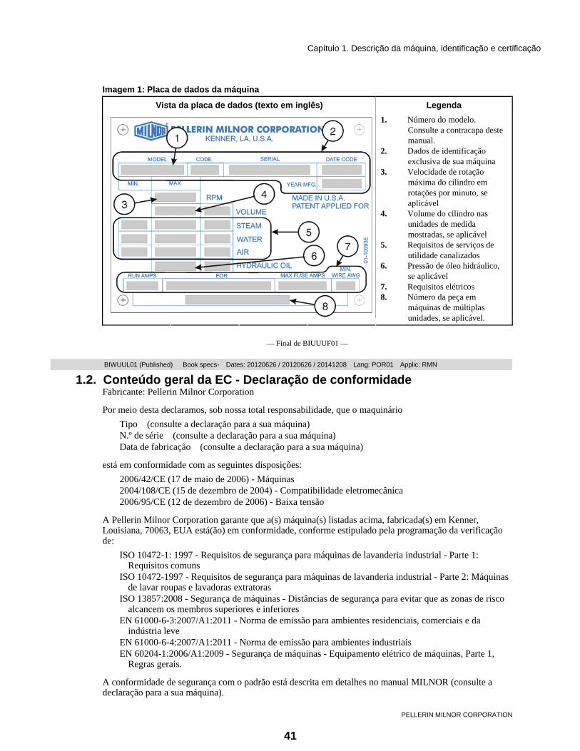
1.1.2. Identificação da máquina Localize o número e outros dados do modelo de sua máquina na placa de dados da máquina afixada à mesma. Observe na figura apresentada a seguir.
40
Capítulo 1. Descrição da máquina, identificação e certificação
PELLERIN MILNOR CORPORATION
Imagem 1: Placa de dados da máquina
Vista da placa de dados (texto em inglês) Legenda
.
1. Número do modelo. Consulte a contracapa deste manual.
2. Dados de identificação exclusiva de sua máquina
3. Velocidade de rotação máxima do cilindro em rotações por minuto, se aplicável
4. Volume do cilindro nas unidades de medida mostradas, se aplicável
5. Requisitos de serviços de utilidade canalizados
6. Pressão de óleo hidráulico, se aplicável
7. Requisitos elétricos 8. Número da peça em
máquinas de múltiplas unidades, se aplicável.
— Final de BIUUUF01 —
BIWUUL01 (Published) Book specs- Dates: 20120626 / 20120626 / 20141208 Lang: POR01 Applic: RMN 1.2. Conteúdo geral da EC - Declaração de conformidade
Fabricante: Pellerin Milnor Corporation
Por meio desta declaramos, sob nossa total responsabilidade, que o maquinário Tipo (consulte a declaração para a sua máquina) N.º de série (consulte a declaração para a sua máquina) Data de fabricação (consulte a declaração para a sua máquina)
está em conformidade com as seguintes disposições: 2006/42/CE (17 de maio de 2006) - Máquinas 2004/108/CE (15 de dezembro de 2004) - Compatibilidade eletromecânica 2006/95/CE (12 de dezembro de 2006) - Baixa tensão
A Pellerin Milnor Corporation garante que a(s) máquina(s) listadas acima, fabricada(s) em Kenner, Louisiana, 70063, EUA está(ão) em conformidade, conforme estipulado pela programação da verificação de:
ISO 10472-1: 1997 - Requisitos de segurança para máquinas de lavanderia industrial - Parte 1: Requisitos comuns
ISO 10472-1997 - Requisitos de segurança para máquinas de lavanderia industrial - Parte 2: Máquinas de lavar roupas e lavadoras extratoras
ISO 13857:2008 - Segurança de máquinas - Distâncias de segurança para evitar que as zonas de risco alcancem os membros superiores e inferiores
EN 61000-6-3:2007/A1:2011 - Norma de emissão para ambientes residenciais, comerciais e da indústria leve
EN 61000-6-4:2007/A1:2011 - Norma de emissão para ambientes industriais EN 60204-1:2006/A1:2009 - Segurança de máquinas - Equipamento elétrico de máquinas, Parte 1,
Regras gerais.
A conformidade de segurança com o padrão está descrita em detalhes no manual MILNOR (consulte a declaração para a sua máquina).
41

Capítulo 1. Descrição da máquina, identificação e certificação
PELLERIN MILNOR CORPORATION
Esta carta confirma que a(s) máquina(s) apenas atende(m) os padrões requeridos acima mencionados. É responsabilidade do instalador/proprietário da(s) máquina(s) garantir a conformidade com todos os requisitos de preparação, instalação e operação no local.
Nossa conformidade com os padrões listados acima é garantida, com as exceções listadas no Relatório de conformidade MILNOR (consulte a declaração para a sua máquina).
Local Kenner, Louisiana, 70063, EUA Data de emissão do tipo de máquina mencionado acima Assinatura Kenneth W. Gaulter Gerente de engenharia
Assinatura Russell H. Poy Vice-presidente, Engenharia
— Final de BIWUUL01 —
42

Capítulo 2. Segurança
PELLERIN MILNOR CORPORATION
Capítulo 2 Segurança
BIUUUS27 (Published) Book specs- Dates: 20120626 / 20120626 / 20141208 Lang: POR01 Applic: RMN 2.1. Segurança —
2.1.1. Requisitos gerais de segurança — Informações essenciais para o pessoal de gerenciamento [Documento BIUUUS04] Instalação incorreta, manutenção preventiva negligenciada, abuso e/ou reparos indevidos, ou alterações na máquina poderão causar operação insegura e ferimentos pessoais, como fraturas múltiplas, amputações ou morte. O proprietário ou seu representante selecionado (proprietário/usuário) são responsáveis por compreender e assegurar o funcionamento e a manutenção adequados da máquina. O proprietário/usuário deverá estar familiarizado com o conteúdo de todos os manuais de instrução da máquina. O proprietário/usuário deverá direcionar quaisquer perguntas sobre estas instruções a um revendedor da Milnor® ou ao Departamento de Manutenção da Milnor®.
A maioria das autoridades regulatórias (incluindo a OSHA nos EUA e a CE na Europa) responsabilizam o proprietário/usuário por manter um ambiente de trabalho seguro. Dessa forma, o proprietário/usuário deverá fazer o seguinte ou assegurar-se de:
• reconhecer todos os riscos de segurança previsíveis em sua instalação e tomar as medidas para proteger o pessoal, o equipamento e a instalação;
• manter equipamento de trabalho adequado, devidamente adaptado e que possa ser usado sem riscos à saúde ou à segurança, tendo passado por manutenção apropriada;
• nos locais em que riscos específicos poderão estar envolvidos, restringir o acesso ao equipamento para os funcionários que receberam a tarefa de usá-lo;
• assegurar que apenas trabalhadores especificamente designados conduzam reparos, modificações, manutenção ou serviço;
• certificar-se de que informações, instruções e treinamento foram fornecidos; • consultar os trabalhadores e/ou seus representantes.
O equipamento de trabalho deverá estar em conformidade com os requisitos listados abaixo. O proprietário/usuário deverá verificar se a instalação e a manutenção do equipamento foram realizadas de forma a atender a esses requisitos:
• os dispositivos de controle deverão estar visíveis, identificáveis e marcados, localizados fora de zonas de perigo e não deverão criar situação de risco devido a operação não intencional;
• sistemas de controle deverão ser seguros e falha/dano não deverá resultar em perigo; • o equipamento de trabalho deverá ser estabilizado; • deverá haver proteção contra ruptura ou desintegração do equipamento de trabalho; • deverá ser fornecida proteção para evitar o acesso a zonas de perigo ou para interromper o movimento
de partes perigosas antes de acessar zonas de perigo. As proteções deverão ser robustas, não provocar riscos adicionais, serem difíceis de remover ou de serem colocadas fora de operação, estar situadas a
43

Capítulo 2. Segurança
PELLERIN MILNOR CORPORATION
uma distância suficiente da zona de perigo, não restringir a visualização do ciclo operacional, permitir o encaixe, a substituição ou a manutenção pela restrição do acesso à área relevante e sem remoção do dispositivo de proteção;
• deverá haver iluminação adequada para as áreas de trabalho e de manutenção; • a manutenção deverá ser possível quando o equipamento de trabalho estiver desligado. Se não for
possível, medidas de proteção deverão ser tomadas fora das zonas de perigo; • o equipamento de trabalho deverá ser apropriado para evitar o risco de fogo ou de superaquecimento,
descargas de gás, poeira, líquido, vapor ou outras substâncias e a explosão do equipamento ou das substâncias nele.
2.1.1.1. Instalação de lavanderia — Deverá oferecer um piso de sustentação forte e rígido o bastante para sustentar–com um fator de segurança razoável e sem deflexão imprópria ou indevida–o peso da máquina totalmente carregada e as forças transmitidas por ela durante a operação. Ofereça espaço suficiente para o movimento da máquina. Forneça quaisquer proteções de segurança, cercas, restrições, dispositivos e restrições verbais e/ou escritas para evitar que pessoal, máquinas ou outro maquinário móvel acesse a máquina ou entre em seu caminho. Forneça ventilação adequada para que calor e vapores sejam retirados. Certifique-se de que as conexões de serviço a máquinas instaladas atendam aos requisitos de segurança padrão, locais e nacionais, especialmente no que diz respeito a disjuntores elétricos (consulte o National Electric Code - Código Elétrico Nacional, nos EUA). Deixa as informações de segurança à vista, incluindo sinais mostrando a fonte do disjuntor elétrico.
2.1.1.2. Pessoal — Informe o pessoal sobre como evitar riscos e sobre a importância do cuidado e do senso comum. Ofereça ao pessoal as instruções operacionais e de segurança aplicáveis. Certifique-se de que o pessoal segue os procedimentos operacionais e de segurança devidos. Verifique se o pessoal compreende e segue os avisos na máquina e as precauções nos manuais de instrução.
2.1.1.3. Dispositivos de segurança — Certifique-se de que ninguém elimine ou desative nenhum dispositivo de segurança na máquina ou na instalação. Não permita que a máquina seja usada sem proteção, tampa, painel ou porta ausente. Realize a manutenção em qualquer dispositivo com falhas ou com mau funcionamento antes de operar a máquina.
2.1.1.4. Informações sobre riscos — Importantes informações sobre riscos são fornecidas nas placas de segurança da máquina, no guia de segurança e ao longo de outros manuais da máquina. Consulte o manual de serviço da máquina para obter os números de peça das placas de segurança. entre em contato com o Departamento de Peças da Milnor para obter placas de substituição ou manuais.
2.1.1.5. Manutenção — Assegure-se de que a máquina seja inspecionada e de que nela seja realizado o serviço de acordo com as normas de boas práticas e com o cronograma de manutenção preventiva. Substitua correias, polias, pastilhas/discos de freio, discos/colares da embreagem, roldanas, vedações, guias de alinhamento e outros, antes que estejam excessivamente gastos. Investigue imediatamente qualquer revestimento de falha iminente e faça os reparos necessários (por exemplo, rachaduras em cilindro, revestimento ou algum quadro, motor ou componentes da transmissão, caixas de câmbio, rolamentos e outros, chiados, rangidos, fumaça ou calor anormal, cilindro, revestimento ou quadro tortos ou rachados, etc.). Não permita pessoal não qualificado realizar serviço ou manutenção.
2.1.2. Mensagens de alerta de segurança — Riscos elétricos e mecânicos internos [Documento BIUUUS11] As seguintes instruções são sobre riscos no interior da máquina e em invólucros elétricos.
ALERTA 1 : Riscos de eletrocução e queimaduras elétricas — O contato com a energia elétrica pode ferir seriamente ou matar. A energia elétrica estará presente no interior do gabinete a menos que o disjuntor principal da máquina esteja desligado. • Não destrave ou abra portas de quadros de energia; • Não remova proteções, tampas ou painéis;
44

Capítulo 2. Segurança
PELLERIN MILNOR CORPORATION
• Não acesse a caixa de proteção ou o quadro da máquina; • Mantenha você e os demais afastados da máquina; • Saiba a localização do disjuntor principal da máquina e use-o em caso de emergência para cortar
toda a energia elétrica da máquina.
ALERTA 2 : Riscos de esmagamento e de se prender — O contato com componentes móveis normalmente isolados por proteções, tampas e painéis pode enroscar ou esmagar seus membros. Esses componentes se movem automaticamente. • Não remova proteções, tampas ou painéis; • Não acesse a caixa de proteção ou o quadro da máquina; • Mantenha você e os demais afastados da máquina; • Saiba a localização de todos os interruptores de parada de emergência, cordas de emergência e/ou
botões de rodapé, usando-os em uma emergência para interromper o movimento da máquina.
2.1.3. Mensagens de alerta de segurança — Riscos de cilindro e de processamento [Documento BIUUUS13] As instruções seguintes referem-se a riscos relacionados ao cilindro e ao processo de lavagem.
PERIGO 3 : Riscos de se prender e de amputação — O contato com bens em processamento poderá fazer com que eles se enrosquem no seu corpo ou membros, desmembrando você. Os bens são, normalmente, isolados pela porta fechada do cilindro. • Não tente abrir a porta ou acessar o cilindro até que este esteja parado; • Não toque nos artigos dentro ou pendurados parcialmente fora do cilindro girando; • Não opere a máquina com um intertravamento de porta com mau funcionamento; • Saiba a localização de todos os interruptores de parada de emergência, cordas de emergência e/ou
botões de rodapé, usando-os em uma emergência para interromper o movimento da máquina. • Saiba a localização do disjuntor principal da máquina e use-o em caso de emergência para cortar
toda a energia elétrica da máquina.
ALERTA 4 : Riscos de esmagamento — O contato com o cilindro girando poderá esmagar seus membros. O cilindro repelirá qualquer objeto que você use para tentar pará-lo, possivelmente fazendo com que esse objeto atinja você ou o perfure. O cilindro giratório é, normalmente, isolado pela porta fechada do cilindro. • Não tente abrir a porta ou acessar o cilindro até que este esteja parado; • Não coloque qualquer objeto no cilindro girando; • Não opere a máquina com um intertravamento de porta com mau funcionamento;
ALERTA 5 : Riscos de espaço confinado — O confinamento no cilindro poderá matá-lo ou feri-lo. Os riscos incluem, mas não se limitam a, pânico, queimaduras, envenenamento, sufocamento, exaustão por calor, contaminação biológica, eletrocussão e esmagamento. • Não tente realizar serviços, reparos ou modificações não autorizados.
ALERTA 6 : Riscos de explosão e de fogo — Substâncias inflamáveis podem explodir ou acender no cilindro, na calha do dreno ou no escoadouro. A máquina foi projetada para ser lavada com água e não com qualquer outro solvente. O processamento poderá fazer com que bens que contenham solvente exalem vapores inflamáveis. • Não use solventes inflamáveis no processamento; • Não processe bens que contenham substâncias inflamáveis. Consulte os bombeiros ou o escritório
de segurança pública local e todos os fornecedores de seguro.
45

Capítulo 2. Segurança
PELLERIN MILNOR CORPORATION
2.1.4. Mensagens de alerta de segurança — Condições inseguras [Documento BIUUUS14]
2.1.4.1. Riscos de dano e de mau funcionamento
2.1.4.1.1. Riscos resultantes de dispositivos de segurança inoperantes
PERIGO 7 : Riscos de se prender e de amputação — Intertravamento da porta do cilindro — operar a máquina com um intertravamento da porta com mau funcionamento poderá permitir a abertura da porta quando o cilindro estiver girando e/ou começando o ciclo com a porta aberta, o que expõe o cilindro girando. • Não opere a máquina com qualquer evidência de dano ou de mau funcionamento.
ALERTA 8 : Riscos diversos — Operar a máquina com um dispositivo de segurança inoperante poderá matar ou ferir o pessoal, danificar ou destruir a máquina, danificar propriedade e/ou anular a garantia. • Não adultere ou desative o dispositivo de segurança, nem opere a máquina com um dispositivo de
segurança com mau funcionamento. Solicite serviço autorizado.
ALERTA 9 : Riscos de eletrocução e queimaduras elétricas — Portas de quadros de energia — operar a máquina com qualquer porta de quadro de energia destravada poderá expor os condutores de alta tensão no interior do quadro. • Não destrave ou abra portas de quadros de energia;
ALERTA 10 : Riscos de esmagamento e de se prender — Proteções, tampas e painéis — operar a máquina com qualquer proteção, tampa ou painel removido exporá os componentes móveis. • Não remova proteções, tampas ou painéis;
2.1.4.1.2. Riscos resultantes de dispositivos mecânicos danificados
ALERTA 11 : Riscos diversos — Operar uma máquina danificada poderá matar ou ferir pessoal, danificar mais a máquina ou destruí-la, danificar propriedade e/ou anular a garantia. • Não opere uma máquina danificada ou com mau funcionamento. Solicite serviço autorizado.
ALERTA 12 : Riscos de explosão — Cilindro — um cilindro danificado poderá romper durante a extração, perfurando o revestimento e lançando fragmentos de metal em alta velocidade. • Não opere a máquina com qualquer evidência de dano ou de mau funcionamento.
2.1.4.2. Riscos por uso descuidado
2.1.4.2.1. Riscos por operação descuidada — Informações essenciais para pessoal de operação (consulte também os perigos para o operador ao longo do manual)
ALERTA 13 : Riscos diversos — Ações descuidadas do operador poderão matar ou ferir pessoas, danificar ou destruir a máquina, danificar propriedade e/ou anular a garantia. • Não adultere ou desative o dispositivo de segurança, nem opere a máquina com um dispositivo de
segurança com mau funcionamento. Solicite serviço autorizado. • Não opere uma máquina danificada ou com mau funcionamento. Solicite serviço autorizado. • Não tente realizar serviços, reparos ou modificações não autorizados. • Não use a máquina de nenhum modo contrário às instruções de fábrica. • Use a máquina apenas para seu propósito costumeiro ou planejado. • Compreenda as consequências da operação manual.
46

Capítulo 2. Segurança
PELLERIN MILNOR CORPORATION
2.1.4.2.2. Riscos por serviço descuidado — Informações essenciais para pessoal de serviço (consulte também os perigos de manutenção ao longo dos manuais)
ALERTA 14 : Riscos de eletrocução e queimaduras elétricas — O contato com a energia elétrica pode ferir seriamente ou matar. A energia elétrica estará presente no interior do gabinete a menos que o disjuntor principal da máquina esteja desligado. • Não realize manutenção na máquina a menos que seja qualificado e autorizado. Você deve
compreender claramente os riscos e como os evitar. • Siga os padrões atuais de lockout/tagout da OSHA quando for necessário realizar o lockout/tagout
segundo as instruções de serviço. Fora dos EUA, siga o padrão da OSHA na ausência de qualquer outro padrão que se sobreponha.
ALERTA 15 : Riscos de esmagamento e de se prender — O contato com componentes móveis normalmente isolados por proteções, tampas e painéis pode enroscar ou esmagar seus membros. Esses componentes se movem automaticamente. • Não realize manutenção na máquina a menos que seja qualificado e autorizado. Você deve
compreender claramente os riscos e como os evitar. • Siga os padrões atuais de lockout/tagout da OSHA quando for necessário realizar o lockout/tagout
segundo as instruções de serviço. Fora dos EUA, siga o padrão da OSHA na ausência de qualquer outro padrão que se sobreponha.
ALERTA 16 : Riscos de espaço confinado — O confinamento no cilindro poderá matá-lo ou feri-lo. Os riscos incluem, mas não se limitam a, pânico, queimaduras, envenenamento, sufocamento, exaustão por calor, contaminação biológica, eletrocussão e esmagamento. • Não entre no cilindro até que ele tenha sido completamente purgado, lavado, drenado, resfriado e
imobilizado. — Final de BIUUUS27 —
BIWUUI06 (Published) Book specs- Dates: 20120626 / 20120626 / 20141208 Lang: POR01 Applic: RMN 2.2. Evitar danos decorrentes de substâncias químicas e sistemas de
produtos químicos
Todas as lavadoras extratoras Milnor® e lavadores túnel CBW® usam aço inoxidável com a especificação AISI 304. Este material oferece bom desempenho quando as substâncias químicas são aplicadas corretamente. Se as substâncias químicas forem aplicadas incorretamente, este material pode ser danificado. O dano pode trazer sérias consequências e pode ocorrer muito rápido.
As empresas de fornecimento de produtos químicos geralmente: • fornecem sistemas de bombas de alimentação de produtos químicos que colocam o material na
máquina; • conectam o sistema de bombas de produtos químicos à máquina; • elaboram fórmulas de lavagem que controlam as concentrações químicas.
A empresa que segue estes procedimentos deve verificar se estes procedimentos não causam danos. A Pellerin Milnor Corporation não se responsabiliza por danos químicos causados às máquinas que ela fabrica ou aos artigos que estejam em uma máquina.
2.2.1. Como as substâncias químicas podem causar danos
2.2.1.1. Substâncias químicas perigosas e fórmulas de lavagem — Alguns exemplos que podem causar danos são:
• uma concentração muito alta de alvejante à base de cloro;
47

Capítulo 2. Segurança
PELLERIN MILNOR CORPORATION
• uma mistura de solução ácida de enxofre [acid sour] e hiperclorito; • substâncias químicas (exemplos: alvejante à base de cloro, ácido hexafluorossilícico) que ficam sobre
o aço inoxidável, por não serem lavadas rapidamente com água.
O livro “Textile Laundering Technology” de Charles L. Riggs oferece dados sobre substâncias químicas corretas e fórmulas.
2.2.1.2. Configuração ou conexão incorreta de equipamentos — Muitos sistemas químicos: • não impedem que haja vácuo no tubo de produtos químicos (por exemplo, com um quebravácuo)
quando a bomba está desligada; • não impedem a vazão (por exemplo, com uma válvula), onde o tubo de produtos químicos entra na
máquina.
Ocorrerá dano se uma substância química entrar na máquina quando o sistema de produtos químicos estiver desligado. Algumas configurações de componentes podem permitir que as substâncias químicas entrem na máquina por um sifão (Imagem 2). Algumas podem permitir que as substâncias químicas entrem na máquina por gravidade (Imagem 3).
48

Capítulo 2. Segurança
PELLERIN MILNOR CORPORATION
Imagem 2: Configurações incorretas que permitem que a substância química entre na máquina através de um sifão
Visões esquemáticas
Legenda
P. Bomba T. Tanque de produtos químicos S. O sifão fica acima aqui. O líquido nas partes do tanque e do tubo de produto químico em cinza pode ir para a
máquina. .
49

Capítulo 2. Segurança
PELLERIN MILNOR CORPORATION
Imagem 3: Configurações incorretas que permitem que a substância química entre na máquina por gravidade
Visões esquemáticas
Legenda
P. Bomba T. Tanque de produtos químicos D. Tubo de produto químico. O líquido nas áreas em cinza pode ir para a máquina.
.
2.2.2. Equipamentos e procedimentos que podem evitar danos
2.2.2.1. Use os tubos de distribuição de produtos químicos fornecidos. — Existe um tubo de distribuição de produtos químicos na máquina para encaixar os tubos de substâncias químicas de um sistema de bombas de produtos químicos. A Figura 3 mostra exemplos. O tubo de distribuição de produtos químicos tem uma fonte de água para lavar o material químico com água.
50

Capítulo 2. Segurança
PELLERIN MILNOR CORPORATION
Imagem 4: Exemplos de tubos de distribuição de produtos químicos para tubos de produtos químicos. Seu equipamento pode ter outra aparência.
2.2.2.2. Feche a tubulação. — Caso a bomba não feche a tubulação sempre que estiver desligada, use uma válvula de corte.
2.2.2.3. Não deixe ocorrer um vácuo. — Coloque um quebravácuo na tubulação de produtos químicos mais elevado do que o nível total do tanque.
2.2.2.4. Lave com água, o tubo de produtos químicos. — Se o líquido que fica no tubo entre a bomba e a máquina pode escorrer para a máquina, lave o tubo com água assim que a bomba parar.
2.2.2.5. Coloque o tubo de produtos químicos totalmente abaixo da entrada da máquina. — Também é necessário que não haja nenhuma pressão no tanque ou no tubo de produtos químicos quando o sistema está desligado. A Imagem 5 mostra esta configuração.
Imagem 5: Uma configuração que impede o fluxo na máquina quando a bomba está desligada (se o tubo de produtos químicos e o tanque estiverem sem pressão)
Visão esquemática Legenda
.
I. Entrada de produtos químicos na máquina
L. Tubo de produtos químicos P. Bomba T. Tanque de produtos
químicos
2.2.2.6. Evitar vazamentos. — Quando você faz a manutenção do sistema de bombas de produtos químicos: • Use os componentes corretos. • Certifique-se de que todas as conexões estejam ajustadas corretamente. • Assegure-se de que todas as conexões estejam apertadas.
— Final de BIWUUI06 —
51

Capítulo 3. Manutenção de rotina
PELLERIN MILNOR CORPORATION
Capítulo 3 Manutenção de rotina
BIUUUM09 (Published) Book specs- Dates: 20120626 / 20120626 / 20141208 Lang: POR01 Applic: RMN 3.1. Manutenção de rotina —
Faça a manutenção descrita na Seção 3.1.2 “Resumo de manutenção” para assegurar que a máquina esteja segura, a garantia seja mantida e que funcione corretamente. Isto também diminuirá o trabalho de manutenção corretiva e os desligamentos indesejados. Fale com o seu revendedor ou com a Milnor se uma manutenção for necessária.
ALERTA 19 : Risco de ferimentos graves — Mecanismos podem puxar e mutilar seu corpo. • Você deve ser aprovado pelo seu empregador antes de realizar este trabalho. • Tenha extremo cuidado quando precisar examinar componentes em funcionamento. Corte a energia
elétrica de todos os outros trabalhos da máquina. Obedeça às normas de segurança. Nos EUA, este é o procedimento de lockout/tagout [parada com travamento] (LOTO) da OSHA. Outras exigências locais podem ser requeridas.
• Substitua as proteções e coberturas que você removeu para a manutenção.
3.1.1. Como mostrar a manutenção em um calendário Se você utiliza o software para manter a programação da manutenção de sua planta, adicione os itens da Seção 3.1.2 àquela programação. Caso contrário, você pode colocar marcas em um calendário que funcionem com as tabelas da Seção 3.1.2. As marcas são os números 2, 3, 4, 5 e 6. Não é necessário mostrar o número 1 (itens que você executa cada dia) no calendário. O número 2 = itens que você executa a cada 40 a 60 horas, 3 = a cada 200 horas, 4 = a cada 600 horas, 5 = a cada 1200 horas e 6 = a cada 2400 horas. Estes são os números de "Marca" na parte superior das colunas estreitas à esquerda de cada tabela na Seção 3.1.2.
A Tabela 1 mostra onde colocar as marcas em um calendário. Por exemplo, se sua máquina funciona entre 41 e 60 horas a cada semana, as três primeiras marcas são 2, 2 e 3. Coloque essas marcas na primeira, segunda e terceira semanas após a máquina entrar em operação. Se você faz a manutenção de rotina em um determinado dia da semana, coloque a marca neste dia em cada semana. Continue a colocar marcas nas semanas subsequentes. Pode ser necessário fazer a manutenção de 40 a 60 horas (2) mais de uma vez por semana. Se a máquina funciona entre 61 e 100 horas, coloque um 2 em dois dias da semana. Se a máquina funciona 101 horas ou mais, coloque um 2 em três dias da semana.
Em cada dia com um 3, faça os itens com um x nas colunas 3 ou 2 de cada tabela na Seção 3.1.2. Em cada dia com um 4, faça os itens com um x nas colunas 4, 3 ou 2. Continue com esse padrão.
52

Capítulo 3. Manutenção de rotina
PELLERIN MILNOR CORPORATION
Tabela 1: Onde colocar as marcas em um calendário Número da Semana Horas/
Semanas 1 2 3 4 5 6 7 8 9 10 11 12 13 14 15 16 17 18 19 20 21 22 23 24 25 26 27 28 29 30 Até 40 2 2 2 2 3 2 2 2 2 3 2 2 2 2 4 2 2 2 2 3 2 2 2 2 3 2 2 2 2 5 41 - 60 2 2 3 2 2 2 3 2 2 4 2 2 3 2 2 2 3 2 2 5 2 2 3 2 2 2 3 2 2 4 61 - 80 2 2 3 2 3 2 4 2 2 3 2 2 3 2 5 2 3 2 2 3 2 4 2 2 3 2 2 3 2 6 81 - 100 2 3 2 3 2 4 2 3 2 3 2 5 2 3 2 3 2 4 2 3 2 3 2 6 repetir 101 - 120 2 3 2 3 4 2 3 2 3 5 2 3 2 3 4 2 3 2 3 6 repetir 121 - 140 2 3 2 3 4 3 2 3 5 2 3 2 3 4 3 2 3 6 repetir
Número da Semana, continuação Horas/ Semana 31 32 33 34 35 36 37 38 39 40 41 42 43 44 45 46 47 48 49 50 51 52 53 54 55 56 57 58 59 60 Até 40 2 2 2 2 3 2 2 2 2 3 2 2 2 2 4 2 2 2 2 3 2 2 2 2 3 2 2 2 2 6 41 - 60 2 2 3 2 2 2 3 2 2 6 repetir
3.1.2. Resumo de manutenção As tabelas nesta seção oferecem os itens da manutenção de rotina da sua máquina. Cada tabela é para um tipo de procedimento (exemplo: aplicar graxa nos rolamentos e buchas). A parte superior da tabela apresenta o procedimento geral. A coluna "Mais Dados" dá instruções especiais, se necessário.
* Se a máquina funciona mais de 12 horas a cada dia, execute os itens do "dia" duas vezes por dia. Execute os outros itens nas horas determinadas ou nos dias em que você marcou no calendário (consulte a Seção 1). Execute todos os itens de todas as tabelas para os intervalos de manutenção que forem aplicáveis (por exemplo, dia, de 40 a 60 horas e 200 horas).
Dica: As seções após o resumo de manutenção apresentam mais dados sobre os itens de manutenção. Depois que você conhecer estes dados, só é necessário consultar o resumo para fazer a manutenção.
Tabela 2: Proteções e componentes relacionados
Examine. Se um componente estiver danificado, faltando ou não definido, corrija isto imediatamente para evitar lesões.
Marca 1 2 3 4 5 6
Execute a cada
Componente Mais Dados
x dia* proteções, coberturas x dia* placas de segurança
Fale com o seu revendedor ou com a Milnor para substituir componentes.
x 200 horas fixadores Os fixadores devem estar apertados. x 200 horas parafusos de ancoragem e
rejuntamento O rejuntamento deve estar bom. Os parafusos devem estar apertados.
x dia* bloqueio de porta Se a máquina continua funcionando com a porta aberta: Desligue a energia elétrica imediatamente. Não permita a operação. Fale com seu o revendedor ou com a Milnor.
53

Capítulo 3. Manutenção de rotina
PELLERIN MILNOR CORPORATION
Tabela 3: Filtros, telas e componentes sensíveis
Remova a contaminação desses componentes para evitar danos e desempenho insatisfatório. Marca
1 2 3 4 5 6
Execute a cada
Componente Mais Dados. Veja também a Seção 3.1.3
“Como remover a contaminação” x 40 a 60 horas ventoinhas de inversores,
aberturas de ventilação, filtros Consulte o Imagem 8. Manter um bom fluxo de ar.
x 600 horas motores Manter um bom fluxo de ar. x 2400 horas toda a máquina Remova a sujeira e poeira excessiva. x dia* áreas de admissão de produtos
químicos Alguma substância química que permanecer nas superfícies da máquina causará dano de corrosão. Consulte o Imagem 9 e Seção 2.2. “Evitar danos decorrentes de substâncias químicas e sistemas de produtos químicos”
x 2400 horas filtros de entrada de água, se fornecidos por terceiros
Remova os filtros das linhas de entrada de água e lave-os com água.
x 2400 horas Filtro no conector de cada válvula no injetor de alimentação de três compartimentos.
Consulte o Imagem 10
x 200 horas filtro(s) de entrada de ar Consulte o Imagem 13 x 200 horas filtro de entrada de vapor.
(Vapor é opcional em alguns modelos).
Consulte o Imagem 12
Tabela 4: Reservatórios de fluidos
Examine. Adicione o fluido, se necessário, e mantenha os componentes limpos para evitar danos. Marca
1 2 3 4 5 6
Execute a cada
Componente Mais Dados. Veja também Seção 3.1.4
“Identificação e procedimentos para lubrificantes”
x 600 horas caixa de rolamento remova o óleo usado. Adicione 22 onças (650 ml) de óleo 30 (Tabela 10). Consulte o Imagem 14
Tabela 5: Componentes que se desgastam
Examine. Aperte ou substitua, se necessário, para evitar desligamentos e desempenho insatisfatório. Fale com o seu revendedor para obter peças de reposição
Marca 1 2 3 4 5 6
Execute a cada
Componente Mais Dados
x 200 horas correias de transmissão e polias Consulte o Suplemento 1 e Imagem 7 x 200 horas tubos e mangueiras Verifique as mangueiras e as conexões das
mangueiras em busca de vazamentos.
54

Capítulo 3. Manutenção de rotina
PELLERIN MILNOR CORPORATION
Tabela 6: Rolamentos e buchas. Veja a Tabela 7 para motores.
Aplique graxa nestes componentes para evitar danos. Marca
1 2 3 4 5 6
Execute a cada
Componente Mais Dados. Veja também a Seção 3.1.4
“Identificação e procedimentos para lubrificantes”
x 600 horas caixa de rolamento O conjunto de rolamentos é imerso em óleo. Nenhuma manutenção de rotina de lubrificação é necessária. A graxa é adicionada à cavidade de lubrificação do retentor do conjunto. Examine o tubo de drenagem da cavidade de lubrificação (Imagem 14). Se houver uma grande quantidade de contaminação ou de fluxos de água do tubo, uma manutenção pode ser necessária. Fale com seu o revendedor ou com a Milnor.Esta não é uma manutenção de rotina.
Tabela 7: Programação de lubrificação do motor. Usar os dados da Seção 3.1.4.2 para completar esta tabela.
Intervalo Quantidade Datas de quando a graxa foi adicionada Identificação do motor (exemplo: unidade principal)
Anos Horas fl oz mL . Tabela 8: Mecanismos e configurações
Certifique-se de que os mecanismos estão em condições de uso e as configurações corretas para evitar desempenho insatisfatório.
Marca 1 2 3 4 5 6
Execute a cada
Componente Mais Dados
x 2400 horas circuito controlador Verifique a fiação e as ligações nas caixas elétricas. Procure por corrosão, conexões frouxas. Consulte o Seção 3.1.3
x 200 horas sensor de nível de banho que utiliza pressão de ar
Verifique o tubo de ar e as conexões. Consulte o Imagem 11
55

Capítulo 3. Manutenção de rotina
PELLERIN MILNOR CORPORATION
3.1.3. Como remover a contaminação Tabela 9: Tipos de contaminação, agentes de limpeza e procedimentos
Material ou componente
Contaminação usual
Exemplo Agente de limpeza Mais Dados
carcaça da máquina poeira, sujeira — ar comprimido ou aspirador de pó
Ar — não mais de 30 psi (207 kpa). Não jogue poeira nos mecanismos.
aletas e aberturas de ventilação em componentes elétricos
poeira motores, inversores, resistores de frenagem
interior da caixa elétrica poeira todas as caixas elétricas
aspirador de pó, escova de cerdas macias, ar comprimido para componentes elétricos
Não jogue poeira nos mecanismos.
ligações elétricas corrosão, verniz conector de pá, conector molex, relé plug-in
solvente em spray para componentes elétricos
Desconecte e, em seguida, conecte novamente. Use o solvente se a conexão ruim continuar.
poeira nenhum Use um pano limpo, macio e seco. sensores eletrônicos sujeira
lente fotoelétrica, refletor, laser, sensor de proximidade, sonda de temperatura
água morna com sabão e, em seguida, lavar com água
Use panos limpos e macios.
aço inoxidável derramamento de produto químico
tanque, injetor de alimentação
água Use uma mangueira para lavar e remover resíduos de produtos químicos totalmente da superfície. Não deixe cair água em componentes elétricos ou mecanismos.
série 300 aço inoxidável ataque de produto químico corrosivo
interior do tanque, cilindro
decapagem e passivação Fale com seu o revendedor ou com a Milnor.Esta não é uma manutenção de rotina.
metal pintado, alumínio sem pintura
poeira, sujeira, graxa
elementos da estrutura
água morna com sabão e, em seguida, água para lavar
Use panos limpos. Não deixe cair água em componentes elétricos.
borracha sujeira, óleo, graxa correias da transmissão, mangueiras
água morna com sabão e, em seguida, água para lavar
Use panos limpos. Lavar completamente. Óleo ou sabão não devem permanecer nas correias de transmissão. Certifique-se de que as correias de transmissão estejam em condições de uso.
plástico transparente, acrílico
descoloração (fica amarelado)
copo do filtro de ar comprimido, medidor visual de fluxo
água morna com sabão e, em seguida, água para enxaguar e depois um fluido de limpeza de acrílico. Não use amônia.
Use apenas os agentes de limpeza necessários. Lave e limpe com panos limpos e macios. Siga as instruções contidas no fluido de limpeza de acrílico.
vidro descoloração (fica amarelado)
vidro da porta, vidro local
solução de amônia e água, enxaguar com água e, em seguida, acetona
Use panos limpos e macios. Use apenas os agentes de limpeza necessários. Se necessário, deixe de molho em um fluido de limpeza.
filtro de ar flexível, filtro de fiapos
poeira, fiapo na porta da caixa elétrica do inversor, no copo do filtro do duto de ar, em secadoras
aspirador de ar Substitua o filtro usado por um novo quando o aspirador de pó não conseguir remover a contaminação.
filtros rígidos, telas para água, vapor
partículas minerais em tubulação de água, filtros em Y
água Use uma escova de limpeza de filtros com cerdas rígidas. Lave com um fluxo de água.
filtros rígidos, telas para óleo
aparas de metal em tubulação hidráulica
fluido de limpeza de carburador ou solvente equivalente
Molho. Use uma escova de limpeza de filtros com cerdas rígidas.
3.1.4. Identificação e procedimentos para lubrificantes Tabela 10 identifica o lubrificante para cada código de lubrificante referido no resumo de manutenção. Use estes lubrificantes ou equivalentes de seu fornecedor local de lubrificantes.
56

Capítulo 3. Manutenção de rotina
PELLERIN MILNOR CORPORATION
Quando você adicionar graxa, siga sempre os procedimentos fornecidos na Seção 3.1.4.1. Quando você adicionar graxa em motores, também deve seguir os procedimentos fornecidos na Seção 3.1.4.2.
CUIDADO 20 : Risco de danos — Lubrificantes ruins diminuirão a vida útil dos componentes. • Certifique-se de que todos os equipamentos e acessórios usados para aplicar os lubrificantes
estejam limpos. • Utilize apenas os lubrificantes determinados ou os equivalentes que tenham as mesmas
especificações. Tabela 10: Identificação de lubrificantes
Código Tipo Nome da marca registrada Exemplo de aplicação EM graxa Mobil Polyrex EM ou como
determinado na placa de identificação do motor
rolamentos do motor
EPLF2 graxa Shell Alvania EP (LF) Tipo 2 rolamentos e buchas do eixo de transmissão, articulações esféricas
30 óleo Óleo de motor, pesado, de alta qualidade versões: SAE 30, 40 ou 50 (não-detergente, se disponível)
pequenos alojamentos de mancais.
3.1.4.1. Procedimentos de pistola de lubrificação
CUIDADO 21 : Risco de danos — A pressão hidráulica pode empurrar os retentores para fora e espalhar graxa em áreas não desejadas (exemplo: bobina do motor). • Use uma pistola de lubrificação. Uma pistola de lubrificação elétrica aplica demasiada pressão. • Saiba a quantidade de graxa que sua pistola de lubrificação aplica a cada ciclo (cada curso). • Opere a pistola de lubrificação lentamente (10 a 12 segundos para cada ciclo). • Adicione somente a quantidade especificada. Pare caso a nova graxa saia por um orifício de
drenagem ou outra abertura. • Remova a graxa derramada em correias e polias. As tabelas especificam as quantidades de graxa em onças fluidas (fl oz) e mililitros (mL). Você também pode usar os ciclos da pistola de lubrificação (cursos). Um ciclo ocorre cada vez que você puxa o gatilho. Um ciclo adiciona geralmente cerca de 0,06 fl oz (1,8 mL). Sua pistola de lubrificação pode aplicar mais ou menos do que isso. Meça a saída de sua pistola de lubrificação da seguinte forma: 1. Certifique-se de que a pistola de lubrificação funcione corretamente. 2. Opere a pistola de lubrificação para colocar graxa em um pequeno recipiente com incrementos de onça
fluida ou mililitro. Puxe o gatilho totalmente e lentamente. 3. Adicione uma quantidade suficiente de graxa para medir com precisão. Conte o número de ciclos da
pistola de lubrificação (o número de vezes que você puxou o gatilho). 4. Calcule a quantidade de cada ciclo da pistola de lubrificação.
Exemplo: 2 fl oz / 64 ciclos = 0,031 fl oz para cada ciclo
Exemplo: 59 mL / 64 ciclos = 0,92 mL para cada ciclo
3.1.4.2. Procedimentos para motores — Se um motor em sua máquina não tiver graxeiras, não há necessidade de manutenção de lubrificação. Se um motor em sua máquina tiver graxeiras, é necessário adicionar graxa. Mas o intervalo é geralmente maior do que para outras manutenções. A Tabela 11 especifica os intervalos e quantidades de graxa para os motores com tamanhos de estrutura e velocidades especificados. Você obtém estes dados na placa de identificação do motor. Use a Tabela 7 na seção 3.1.2 para gravar os dados dos motores de sua máquina.
57

Capítulo 3. Manutenção de rotina
PELLERIN MILNOR CORPORATION
Imagem 6: Condições de manutenção de lubrificação do motor
Encaixe do bocal e saída de graxa Encaixe do bocal e dreno de graxa
Placa de identificação do motor Graxeiras, sem saídas ou drenos
Legenda 1. Encaixe do bocal 2. Alívio de graxa. Não remova. 3. Bujão de drenagem de graxa. Remova primeiro. 4. RPM (velocidade do motor). Este exemplo é
1465 RPM a 50 Hz e 1765 RPM a 60 Hz. 5. Tamanho de estrutura NEMA (IEC). Exemplo:
256T .
CUIDADO 22 : Risco de danos — Você pode derramar graxa na bobina e queimar o motor, se você não conseguir remover os bujões de drenagem de graxa. • Se o motor tiver bujões de drenagem de graxa, remova-os antes de adicionar graxa. Se o motor tem
graxeiras com saídas de graxa, não é necessário removê-las. Aplique graxa como segue: 1. Opere a máquina ou use funções manuais para operar o motor até que esteja aquecido. 2. Desligue a energia elétrica da máquina. 3. Se o motor tiver bujões de drenagem de graxa, remova-os. Consulte o relatório de cuidado 22 .
58

Capítulo 3. Manutenção de rotina
PELLERIN MILNOR CORPORATION
4. Adicione a graxa EM (Tabela 10) com o motor parado. Se o motor com a placa de identificação da Imagem 6 opera a 60 Hz, a quantidade de graxa especificada para cada encaixe do bocal é de 0,65 fl oz (18,4 mL).
5. Se o motor possuir bujões de drenagem de graxa, opere a máquina ou use funções manuais para operar o motor por duas horas. Substitua o bujão de drenagem.
Tabela 11: Intervalos e quantidades de graxa para o motor. Usar a graxa EM (Tabela 10)
Na placa de identificação do motor (veja Imagem 6)
Intervalo Quantidade
Tamanho de estrutura NEMA
(IEC)
RPM menor ou igual a
Anos Horas Onças fluidas
mL
900 5,5 11000 1200 4,5 9000 1800 3 6000
Até 210 (132)
3600 1,5 3000
0,34 9,5
900 4,5 9000 1200 3,5 7000 1800 2,5 5000
>210 a 280 (132 a 180)
3600 1 2000
0,65 18,4
900 3,5 7000 1200 3 6000 1800 2 4000
>280 a 360 (180 a 200)
3600 0,5 1000
0,87 24,6
900 2,5 5000 1200 2 4000 1800 1 2000
>360 a 5000 (200 a 300)
3600 0,5 1000
2,23 63,2
3.1.5. Componentes de manutenção — Grupo máquinas e controles [Documento BIUUUM10]
Suplemento 1
Como examinar as correias e polias
Verifique as correias e polias, conforme explicado a seguir.
Com a energia elétrica desligada: • Procure por sujeira, poeira, óleo e graxa. Remova a contaminação. • Procure por danos na correia conforme mostrado na Imagem 7. • Procure por polias gastas, conforme exibido na Imagem 7.
Com a máquina em funcionamento — Não toque na máquina. Observe e escute: • Uma correia pode ter alguma vibração e não causar danos. É necessário corrigir esta condição
somente se a vibração for grande. • Uma correia deve ter tensão suficiente, de modo que não haja nenhum deslizamento na polia durante
a operação. Se algum deslizamento estiver ocorrendo, você geralmente pode saber pelo ruído.
Sobre a substituição de componentes e o ajuste de tensão — Um ajuste correto é muito importante
59

Capítulo 3. Manutenção de rotina
PELLERIN MILNOR CORPORATION
para a vida útil dos componentes e o funcionamento da máquina. O seu revendedor Milnor pode fazer este trabalho. Se você sabe como fazer este trabalho (por exemplo, alinhar corretamente as correias e polias) e deseja fazê-lo, fale com o seu revendedor ou com a Milnor para saber os números das peças. Substitua os componentes desgastados antes de fazer os ajustes de tensão.
• Máquinas que usam hastes com rosca inteira e porcas para manter a posição da base do motor — gire as porcas sobre as hastes conforme necessário para ajustar a tensão. Aperte as porcas.
• Máquinas que usam uma mola para manter a tensão da base do motor — Use o tubo de metal fornecido com a máquina. Coloque o tubo na haste onde a mola está ligada ou remova o tubo para aumentar ou diminuir a tensão. Se necessário, substitua a mola.
Imagem 7: Condições a procurar em correias e polias. Consulte o Suplemento 1.
Tipos de danos de correia Como encontrar uma polia desgastada
Legenda
.
1. Cordão quebrado — danos causados por um objeto afiado.
2. Trinca — a correia é muito grande para a polia. 3. Paredes laterais brilhantes — óleo ou graxa na
correia. 4. Separação de camadas da correia — Óleo ou
graxa. 5. Faixas nas paredes laterais — sujeira, partículas. 6. Incorreto: A polia está muito desgastada. 7. Correto: A correia apenas toca nas paredes
laterais. É possível colocar uma tira fina de papel no espaço entre a correia e a polia.
8. Espaço
60

Capítulo 3. Manutenção de rotina
PELLERIN MILNOR CORPORATION
Imagem 8: Caixa elétrica e inversor. Estes são apenas exemplos. Sua máquina pode ter outra aparência.
30022X_ Lavadora Extratora 48040F_ Lavadora Extratora 76039 CBW Lavadora de Túnel
Legenda 1. Filtro de ar 2. Ventilador na porta da caixa elétrica. Dica: Coloque fitas de papel na frente do ventilador para certificar-se
de que está funcionando. 3. Aletas de refrigeração e aberturas de ventilação do inversor. Consulte o relatório de cuidado 23 . 4. Resistor de frenagem, se aplicável
.
CUIDADO 23 : Risco de danos — O inversor queimará sem um fluxo de ar suficiente. • Mantenha os ventiladores, filtros, aberturas de ventilação e resistores de frenagem limpos.
Imagem 9: Tubos de distribuição de entrada de produtos químicos para sistemas de bombas de produtos químicos. Consulte o relatório de cuidado 24 . Estes são apenas exemplos. Sua máquina pode ter outra aparência.
36026V7J 60044WP2 76039CBW
.
CUIDADO 24 : Risco de dano de corrosão para a máquina e para os artigos — • Ligue os tubos de substâncias químicas somente às entradas dos tubos de distribuição de produtos
químicos. • Impeça vazamentos. Remova das superfícies as substâncias que vazaram.
61

Capítulo 3. Manutenção de rotina
PELLERIN MILNOR CORPORATION
• Fale com o seu revendedor ou com a Milnor se você observar danos de corrosão.
CUIDADO 25 : Risco de lesões e danos — As substâncias químicas podem espirrar no pessoal e nas superfícies da máquina se a pressão da água for muito alta. • Certifique-se de que a pressão seja estabelecida conforme especificado no resumo de manutenção.
Imagem 10: Canaleta e injetor opcional de alimentação de três compartimentos.
Injetor de alimentação Válvulas no compartimento de válvulas
Canaleta de sabão
Legenda 1. Não deixe que as substâncias químicas permaneçam nas superfícies
de aço inoxidável. 2. Compartimento de válvulas 3. Filtro (um de três)
.
62

Capítulo 3. Manutenção de rotina
PELLERIN MILNOR CORPORATION
Imagem 11: Tubo de ar para o sensor de nível de água. Estes são apenas exemplos. Sua máquina pode ter outra aparência.
30022T5E Lavadora Extratora 42044SP2 Lavadora Extratora 36030F8_ Lavadora Extratora
30022V6J Lavadora Extratora
Legenda
1. Interruptores de nível 2. Transdutor de pressão 3. Tubo de ar. Veja o relatório
de cuidado 26 . 4. Câmara de ar
.
CUIDADO 26 : Risco de avaria — O sensor de nível deve informar dados corretos. • Mantenha o tubo ou mangueira livre de obstruções e vazamentos. • Assegure-se de que as conexões estejam apertadas.
Imagem 12: Filtro de entrada de vapor. Estes são apenas exemplos. Sua máquina pode ter outra aparência.
42044SP2 Lavadora Extratora 76039CBW Lavadora de Túnel Legenda 1. Filtro de vapor. Remova a
pressão do vapor antes de remover o bujão. Veja o relatório de alerta 27
2. Válvula de vapor
.
ALERTA 27 : Risco de ferimentos graves — Você pode acidentalmente liberar vapor pressurizado. • Feche a válvula externa de corte e libere a pressão residual antes de fazer a manutenção.
63

Capítulo 3. Manutenção de rotina
PELLERIN MILNOR CORPORATION
Imagem 13: Filtros de entrada de ar comprimido. Estes são apenas exemplos. Sua máquina pode ter outra aparência.
Filtro do tipo T. Estrutura exterior da máquina para alguns
modelos.
Filtro do tipo T. Estrutura interior da máquina para alguns
modelos.
Filtro do tipo Y. Usado em alguns modelos
Legenda 1. Consulte o relatório de cuidado 28 . Remova o bujão para
remover o filtro. 2. Entrada de ar comprimido.
.
CUIDADO 28 : Riscos de lesões e danos — • Feche a válvula externa de corte e libere a pressão residual antes de fazer a manutenção.
3.1.6. Componentes de manutenção — Extratoras Grandes [Documento BIWUUM03]
Imagem 14: Áreas de manutenção de óleo do conjunto de rolamentos. Uma 30022T5E é mostrada. Sua máquina pode ter outra aparência.
Vistas das áreas de manutenção Legenda
.
1. Porta de drenagem de óleo. Ao remover o óleo usado, não permita que o óleo atinja o motor ou outros componentes.
2. Tubo de enchimento de óleo e tampa. Não permita que o óleo novo atinja os componentes do console.
3. Bujão de respiro do alojamento
4. Tubo de drenagem da cavidade de vedação. Remova a contaminação que flui do tubo.
— Final de BIUUUM09 —
64

Nederlands 3
65


Published Manual Number: MQRMNM01NL • Specified Date: 20120626• As-of Date: 20120626• Access Date: 20170503• Depth: Detail• Custom: n/a• Applicability: RMN• Language Code: DUT01, Purpose: publication, Format: 1colA
Onderhoud— 30-serie, OPL-was-/extractiemachine in consolestijl WARRSCHUWING: De in deze handleiding opgenomen informatie is door Pellerin Milnor Corporation alleen in het Engels voorzien. Milnor heeft getracht een vertaling van goede kwaliteit te verkrijgen, maar maakt geen claims, doet geen beloften en biedt geen garanties betreffende de nauwkeurigheid, volledigheid of adequaatheid van de in de niet-Engelse versie opgenomen informatie.
Bovendien heeft Milnor geen enkele poging gedaan de in de niet-Engelse versie opgenomen informatie te controleren, aangezien dit geheel door derden is gedaan. Om deze redenen wijst Milnor uitdrukkelijk elke aansprakelijkheid voor fouten wat betreft inhoud of vorm af en neemt zij geen enkele verantwoordelijkheid op zich voor vertrouwen op, of gevolgen van, het gebruik van de informatie in de niet-Engelse versie.
Milnor, of diens lasthebbers of functionarissen, zijn in geen enkel geval aansprakelijk voor directe, indirecte, incidentele of strafrechtelijke schade of gevolgschade die op welke wijze dan ook het gevolg is van het gebruik van, of onvermogen tot gebruik van, of vertrouwen op, de niet-Engelse versie van deze handleiding, of die het gevolg is van fouten, weglatingen of vergissingen in de vertaling.
Lees de veiligheidshandleiding
PELLERIN MILNOR CORPORATION POST OFFICE BOX 400, KENNER, LOUISIANA 70063 - 0400, U.S.A.
67

Toepasselijk Milnor® producten op modelnummer:
30010G5E 30010G5X 30015G5E 30015G5X 30015M4A 30015M4G 30015M4J 30015M4T 30015M6A 30015M6G 30015M6J 30015M6T 30015S5G 30015S5J 30015S5T 30015T5E 30015T5J 30015T5X 30015V7J 30022M5G 30022M5J 30022M5T 30022S4G 30022S4J 30022S4T 30022S5G 30022S5J 30022S5T 30022T5E 30022T5J 30022T5X 30022V6J 30022V8Z
68

Inhoudsopgave
PELLERIN MILNOR CORPORATION
Inhoudsopgave Secties Afbeeldingen, tabellen en supplementen
Hoofdstuk 1. Machinebeschrijving, identificatie en certificering
1.1. Informatie over deze Milnor® machine— (Document BIUUUF01)
1.1.1. Functiebeschrijving 1.1.2. Machine-identificatie Afbeelding 1: Machinegegevensplaatje
1.2. Algemene inhoud van de EG-verklaring van overeenstemming (Document BIWUUL01)
Hoofdstuk 2. Veiligheid
2.1. Veiligheid— (Document BIUUUS27) 2.1.1. Algemene Veiligheids Eisen—Essentiële informatie voor
Management personeel. (Document BIUUUS04)
2.1.1.1. Wasserij Bedrijf 2.1.1.2. Personeel / Medewerkers 2.1.1.3. Veiligheids Onderdelen 2.1.1.4. Risico-informatie 2.1.1.5. Onderhoud
2.1.2. Veiligheidswaarschuwingen—Intern Elektrisch en Mechanisch Gevaar (Document BIUUUS11)
2.1.3. Veiligheidswaarschuwingen—Trommel en Programma Gevaar (Document BIUUUS13)
2.1.4. Veiligheidswaarschuwingen—Onveilige voorwaarde (Document BIUUUS14)
2.1.4.1. Schade en defekt Gevaar 2.1.4.1.1. Risico's Door Buiten Gebruik Zijnde Veiligheids
Onderdelen
2.1.4.1.2. Risico's Door Defekte Mechanische Onderdelen 2.1.4.2. Gevaar bij onzorgvuldig gebruik
2.1.4.2.1. Slordige Bedienings Risico's-Essentiële Informatie voor Bedienings Personeel (Zie ook Bedienings Waarschuwingen in de gehele handleiding)
2.1.4.2.2. Nalatige Service/Onderhouds Risico's-Essentiële Informatie voor Onderhouds Personeel (Zie ook onderhouds waarschuwingen in de gehele handleiding)
2.2. Schade door chemicaliën en chemische systemen voorkomen (Document BIWUUI06)
2.2.1. Hoe chemicaliën schade kunnen veroorzaken
69

Inhoudsopgave
PELLERIN MILNOR CORPORATION
Secties Afbeeldingen, tabellen en supplementen
2.2.1.1. Gevaarlijke chemicaliën en wasformules 2.2.1.2. Onjuiste configuratie of aansluiting van apparatuur Afbeelding 2: Onjuiste configuraties die
chemicaliën de machine in laten lopen via een sifon
Afbeelding 3: Onjuiste configuraties die chemicaliën de machine in laten lopen door middel van de zwaartekracht
2.2.2. Uitrustingen en procedures die schade kunnen voorkomen 2.2.2.1. Gebruik de meegeleverde chemische verdeler. Afbeelding 4: Voorbeelden van verdelers
voor chemische leidingen. Uw apparatuur kan er anders uitzien.
2.2.2.2. Sluit de leiding. 2.2.2.3. Zorg dat er geen vacuüm ontstaat. 2.2.2.4. Spoel de chemische leiding met water. 2.2.2.5. Plaats de gehele chemische leiding lager dan de inlaat
van de machine. Afbeelding 5: Een configuratie die instroom in de machine voorkomt als de pomp is uitgeschakeld (als de chemische leiding en tank geen druk hebben)
2.2.2.6. Lekken voorkomen.
Hoofdstuk 3. Routineonderhoud
3.1. Routineonderhoud— (Document BIUUUM09) 3.1.1. Het onderhoud weergeven op een kalender Tabel 1: Markeringen op de kalender
zetten 3.1.2. Overzicht onderhoud Tabel 2: Beschermingen en gerelateerde
onderdelen Tabel 3: Filters, zeven en gevoelige
onderdelen Tabel 4: Vloeistofcontainers Tabel 5: Onderdelen die verslijten Tabel 6: Lagers en bussen. Zie Tabel 7
voor motoren. Tabel 7: Schema motorsmering. Gebruik
de gegevens in Sectie 3.1.4.2 om deze tabel aan te vullen.
Tabel 8: Mechanismen en instellingen 3.1.3. Verontreinigingen verwijderen Tabel 9: Soorten verontreiniging,
reinigingsmiddelen en procedures 3.1.4. Identificatie en procedures voor smeermiddelen Tabel 10: Identificatie van smeermiddelen
3.1.4.1. Procedures voor vetspuit
70

Inhoudsopgave
PELLERIN MILNOR CORPORATION
Secties Afbeeldingen, tabellen en supplementen
3.1.4.2. Procedures voor motoren Afbeelding 6: Voorwaarden voor motorsmeringonderhoud
Tabel 11: Intervallen en hoeveelheden voor motorsmering Gebruik vet EM (Tabel 10)
3.1.5. Onderhoudsonderdelen—machines en bedieningsgroep (Document BIUUUM10)
Supplement 1: Banden en riemschijven controleren
Afbeelding 7: Toestanden van band en riemschijf om naar uit te kijken. Zie Supplement 1.
Afbeelding 8: Elektriciteitskast en omvormer. Dit zijn voorbeelden. Uw machine kan er anders uitzien.
Afbeelding 9: Chemische inlaatverdelers voor pompsystemen voor chemicaliën. Zie verklaring betreffende voorzichtigheid 24 . Dit zijn voorbeelden. Uw machine kan er anders uitzien.
Afbeelding 10: Zeepgoot en optioneel zeepcompartiment met 3 kamers
Afbeelding 11: Luchtslang voor de waterpeilsensor. Dit zijn voorbeelden. Uw machine kan er anders uitzien.
Afbeelding 12: Stoominlaatzeef. Dit zijn voorbeelden. Uw machine kan er anders uitzien.
Afbeelding 13: Inlaatzeven perslucht. Dit zijn voorbeelden. Uw machine kan er anders uitzien.
3.1.6. Onderhoudsonderdelen—Grote extractiemachines (Document BIWUUM03)
Afbeelding 14: Olie-onderhoudsgedeelten voor lagers. A 30022T5E wordt weergegeven. Uw machine kan er anders uitzien.
71

Hoofdstuk 1. Machinebeschrijving, identificatie en certificering
PELLERIN MILNOR CORPORATION
Hoofdstuk 1 Machinebeschrijving, identificatie en certificering
BIUUUF01 (Published) Book specs- Dates: 20120626 / 20120626 / 20170503 Lang: DUT01 Applic: RMN 1.1. Informatie over deze Milnor® machine—
Deze handleiding is van toepassing op de Milnor-producten waarvan de modelnummers binnen in de voorkant te vinden zijn en in de onderstaande machinefamilies.
1.1.1. Functiebeschrijving Wasmachines-extractiemachines was het wasgoed met water en niet-vluchtige chemicaliën en verwijder overtollig water met centrifugale kracht.
30-serie, OPL-was-/extractiemachine in consolestijl modellen zijn robuuste, zichtbare shell was/-extractiemachines met een cilinderdiameter van 30 inches (762 mm) voor gebruik in verzorgingstehuizen, scholen en soortgelijke wasserij-activiteiten ter plaatse.
1.1.2. Machine-identificatie Het modelnummer en andere gegevens van uw machine zijn te vinden op het machinegegevensplaatje dat op de machine is bevestigd. Zie onderstaande afbeelding.
72

Hoofdstuk 1. Machinebeschrijving, identificatie en certificering
PELLERIN MILNOR CORPORATION
Afbeelding 1: Machinegegevensplaatje
Aanzicht van gegevensplaatje (Engelse tekst) Randschrift
1. Modelnummer. Zie de binnenkant van de omslag van deze handleiding.
2. Gegevens die uw machine identificeren.
3. Maximale cilindertoerental in omwentelingen per minuut, indien van toepassing
4. Cilindervolume in maateenheden weergegeven, indien van toepassing
5. Vereisten voor leidingstelsel 6. Hydraulische oliedruk,
indien van toepassing 7. Vereisten voor elektriciteit 8. Onderdeelnummer voor
machine met meerdere eenheden, indien van toepassing .
— Einde BIUUUF01 —
BIWUUL01 (Published) Book specs- Dates: 20120626 / 20120626 / 20170503 Lang: DUT01 Applic: RMN 1.2. Algemene inhoud van de EG-verklaring van overeenstemming
Fabrikant: Pellerin Milnor Corporation
Wij verklaren uitsluitend op eigen verantwoordelijkheid dat de machines Type (zie de verklaring voor uw machine) Serienummer (zie de verklaring voor uw machine) Fabricagedatum (zie de verklaring voor uw machine)
voldoet aan alle voorwaarden zoals vastgesteld in 2006/42/EC (17 mei 2006) - Machines 2004/108/EC (15 december 2004) - Elektromechanische compatibiliteit 2006/95/EC (12 december 2006) - laag voltage
Pellerin Milnor Corporation verklaart dat de hierboven vermelde machines, gefabriceerd in Kenner, Louisiana, 70063, VS, voldoen zoals gesteld in het controleschema voor
ISO 10472-1:1997 - Veiligheidseisen voor industriële wasmachines - deel 1: Algemene eisen ISO 10472-2:1997 - Veiligheidseisen voor industriële wasmachines - deel 2: Wasmachines en
was-/extractiemachines ISO 13857:2008 - Veiligheid van machines - Veiligheidsafstanden ter voorkoming van het bereiden
van gevaarlijke zones met de onderste en bovenste ledematen EN 61000-6-3:2007/A1:2011 - Emissienorm voor woon-, werk- en licht industriële omgevingen EN 61000-6-4:2007/A1:2011 - Emissienorm voor industriële omgevingen EN 60204-1:2006/A1:2009 - Veiligheid van machines - Elektrische uitrusting van machines, Deel een,
Algemene eisen.
Veiligheidsnaleving van de norm wordt gedetailleerd beschreven in de MILNOR-handleiding (zie de verklaring voor uw machine).
73

Hoofdstuk 1. Machinebeschrijving, identificatie en certificering
PELLERIN MILNOR CORPORATION
Deze brief bevestigt dat de machines alleen voldoen aan de vereiste hierboven genoemde normen. Het is de verantwoordelijkheid van de installateur/eigenaar van de machines om naleving van alle eisen voor voorbereiding, installatie en gebruik op locatie te controleren.
Onze overeenstemming met de hierboven vermelde normen is gecertificeerd met uitzonderingen zoals vermeld in het MILNOR Conformance Report (zie de verklaring voor uw machine).
Plaats Kenner, Louisiana, 70063, USA Datum van eerste uitgifte van het hierboven genoemde type machine Handtekening Kenneth W. Gaulter Engineering Manager
Handtekening Russell H. Poy Vice President, Engineering
— Einde BIWUUL01 —
74

Hoofdstuk 2. Veiligheid
PELLERIN MILNOR CORPORATION
Hoofdstuk 2 Veiligheid
BIUUUS27 (Published) Book specs- Dates: 20120626 / 20120626 / 20170503 Lang: DUT01 Applic: RMN 2.1. Veiligheid—
2.1.1. Algemene Veiligheids Eisen—Essentiële informatie voor Management personeel. [Document BIUUUS04] Incorrecte installatie, nagelaten preventief onderhoud, misbruik, en/of verkeerde reparaties, of wijzigingen aan de machine kunnen onveilige werking en persoonlijke ongevallen veroorzaken, zoals meervoudige frakturen, amputaties of met dodelijke afloop. De eigenaar of beheerder is verantwoordelijk voor de werking van de machine en moet zorgdragen voor goede bediening en onderhoud. De eigenaar/gebruiker moet op de hoogte zijn van de inhoud van alle instruktie boeken. De eigenaar/gebruiker behoort vragen over de instrukties alleen aan een Milnor® dealer of de Milnor® Service afdeling te stellen.
De meeste regelgevende instanties (inklusief OSHU in de VS en de CE in Europa) houden de eigenaar/gebruiker uiteindelijk verantwoordelijk voor het zorgen voor een veilige werkomgeving. Daarom moet de eigenaar het volgende doen of garanderen:
• herkennen van alle zichtbare veiligheids risico's/gebreken binnen zijn bedrijf en aktie ondernemen om zijn personeel, apparatuur en bedrijf te beschermen.
• de installatie is geschikt, goed geïnstalleerd, kan gebruikt worden zonder risico voor gezondheid of veiligheid, en is naar behoren onderhouden
• waar het specifieke gevaren betreft, is toegang tot de installatie beperkt tot aangewezen personeel om het te gebruiken;
• alleen met name aangestelde medewerkers voeren reparaties, modificaties, onderhoud of service uit; • informatie, instruktie en opleiding is voorzien; • medewerkers en/of hun vervangers zijn geraadpleegd.
De installatie moet voldoen aan de eisen zoals onderstaand weergegeven. De eigenaar/gebruiker moet controleren dat het installeren en onderhouden van de installatie zodanig is gebeurd dat het overeenkomt met deze eisen:
• besturings apparaten moeten zichtbaar, herkenbaar en gemerkt zijn; geplaatst zijn buiten gevaar zones; en geen gevaar opleveren bij verkeerd gebruik;
• besturings systemen moeten veilig zijn en uitvallen of schade moet geen gevaar opleveren; • de installatie moet gestabiliseerd zijn; • bescherming tegen scheuren en uiteenvallen van een installatie; • hekken/afzettingen, ter voorkoming van het binnengaan van gevaarlijke zones of voor het stoppen van
gevaarlijke bewegende delen voordat ze de gevaren zone bereiken. Hekken dienen stevig te zijn; geen extra gevaar op te leveren; niet gemakkelijk te verwijderen of buiten gebruik te stellen zijn; geplaatst op voldoende afstand van de gevaren zone; geen uitzicht te belemmeren op het proces; aanpassen,
75

Hoofdstuk 2. Veiligheid
PELLERIN MILNOR CORPORATION
vervangen of onderhoud niet te belemmeren in de nabije omgeving en zonder verwijdering van deze hekken;
• geschikte verlichting voor werk- en onderhouds omgeving; • onderhoud moet mogelijk zijn als de installatie buiten gebruik is. Indien niet mogelijk, dan
beschermings verordeningen buiten de gevaren zones; • de installatie moet uitgerust zijn ter voorkoming van brand of oververhitting; lekken van gas, stof,
vloeistof, damp, andere substanties; exploderen van de installatie of subsanties erin.
2.1.1.1. Wasserij Bedrijf —Zorg voor een vloer die sterk en stijf genoeg is om, met redelijke veiligheids factor/marge en zonder overmatige of bedenkelijke buigingû het gewicht van een geladen machine en de vrijkomende krachten tijdens het werken, de machine te dragen. Geef de machine voldoende ruimte om te bewegen. Zorg voor veiligheids kettingen, hekken, belemmeringen, apparaten en mondelinge en/of aangeplakte waarschuwingen om te voorkomen dat personeel, machines en andere bewegende machines in de nabijheid komen. Zorg voor adequate/goede ventilatie om hitte en dampen af te voeren. Zorg voor goede aansluitingen bij de geïnstalleerde machines die voldoen aan de plaatselijke en landelijke eisen, vooral voor de elektrische aansluiting. Opvallende veiligheids informatie, inclusief aanwijzing die de oorsprong van de elektrische aansluiting laten zien.
2.1.1.2. Personeel / Medewerkers—Informeer het personeel over risico vermijding en het belang van zorg en gezond verstand. Voorzie het personeel van de veiligheids en bedienings voorschriften die bij hun funktie horen. Kontroleer dat het personeel de goede veiligheids en bedienings procedures hanteert. Kontroleer of het personeel de waarschuwingen op de machine en de voorzorgsmaatregelen in de handleidingen begrijpt en zich eraan houdt.
2.1.1.3. Veiligheids Onderdelen—Verzeker u ervan dat niemand enig veiligheids onderdeel van de machine of in de fabriek weghaalt of buiten gebruik stelt.
2.1.1.4. Risico-informatie—Op de veiligheidsplaatjes op de machine, in de veiligheidshandleiding en in de andere machinehandleidingen wordt belangrijke informatie over de risico's gegeven. Raadpleeg de onderhoudshandleiding van de machine voor onderdeelnummers van veiligheidsplaten. Neem contact op met de onderdelenafdeling van Milnor voor vervangende platen of handleidingen.
2.1.1.5. Onderhoud—Zorg ervoor dat de machine gekontroleerd en onderhouden wordt aan de hand van de normen van de praktijk en met een preventief onderhouds schema. Vervang banden, snaarschijven, remschoenen/schijven, koppelings platen/wielen, hulpwielen, seals, langsgeleidingen etc. voordat ze geheel versleten zijn. Onderzoek onmiddelijk mogelijk bewijs van dreigende storing en doe de noodzakelijke reparaties (b.v., trommel, voorfront of frame breuken; aandrijfonderdelen zoals motoren, vertragingskasten, lagers, etc., janken, knarsen, roken, of buitengewoon warm worden; buigen of kraken van de trommel, voorfront of frame, etc.; lekkende seals, slangen, ventielen/afsluiters, etc.) Laat geen onderhoud plegen door niet gekwalificeerd personeel.
2.1.2. Veiligheidswaarschuwingen—Intern Elektrisch en Mechanisch Gevaar [Document BIUUUS11] Hieronder vindt u informatie over de risico's in de machine en in elektrische behuizingen.
WAARSCHUWING 1 : Elektrocutie en verbrandingsgevaar door elektriciteit—Contact met elektrische spanning kan de dood of ernstig letsel tot gevolg hebben. In de machine is elektriciteitsspanning aanwezig, tenzij de hoofdvoeding van de machine is uitgeschakeld. • Wees voorzichtig bij het openen van elektrische deuren met componenten. • Haal geen kettingen, kappen of panelen weg. • Reik niet in de machine of tussen het frame. • Houdt uzelf en anderen van de machine. • Zorg er steeds voor dat u zelf de hoofdschakelaar uitschakelt voordat u aan de machine gaat
76

Hoofdstuk 2. Veiligheid
PELLERIN MILNOR CORPORATION
werken en controleer met een goed werkend meetinstrument of er nog spanning op de machine aanwezig is. Zorg ervoor dat niemand anders de hoofdschakelaar kan omzetten tijdens het werken.
WAARSCHUWING 2 : Vastloop / Verstrik en Verpletter Gevaar—Kontakt met bewegende delen kunnen uw ledematen verpletteren , sommige bewegingen worden automatisch uitgevoerd. De bewegende delen zijn afgeschermd met de nodige kettingen, kappen en platen. • Haal geen kettingen, kappen of panelen weg. • Reik niet in de machine of tussen het frame. • Houdt uzelf en anderen van de machine. • Zorg dat u weet waar de noodschakelaar, trekkoorden en/of veiligheids-platen zitten, en gebruik ze
bij nood om de machine te stoppen.
2.1.3. Veiligheidswaarschuwingen—Trommel en Programma Gevaar [Document BIUUUS13] Hieronder vindt u informatie over de risico's met betrekking tot de cilinder en het wasproces.
GEVAAR 3 : Gevaar voor vastlopen/verstrikt raken en afbreken—Kontakt met te verwerken goederen kunnen de goederen om uw lichaam en ledematen draaien en u uiteen rijten / uitschakelen. De goederen zijn normaal gesproken afgeschermd door een gesloten trommel deur. • Probeer niet de deur te openen of in de trommel te reiken voordat de trommel gestopt is. • Raak geen goederen aan die in de draaiende trommel liggen of die er gedeeltelijk uithangen • Gebruik de machine niet met een niet funktionerend veiligheids deurslot • Zorg dat u weet waar de noodschakelaar, trekkoorden en/of veiligheids-platen zitten, en gebruik ze
bij nood om de machine te stoppen. • Zorg er steeds voor dat u zelf de hoofdschakelaar uitschakelt voordat u aan de machine gaat
werken en controleer met een goed werkend meetinstrument of er nog spanning op de machine aanwezig is. Zorg ervoor dat niemand anders de hoofdschakelaar kan omzetten tijdens het werken.
WAARSCHUWING 4 : Verpletter Gevaar—Kontakt met de draaiende trommel kan uw ledematen verpletteren of afrukken. Tracht de trommel niet te stoppen met uw handen of andere vreemde voorwerpen. De deur moet gesloten zijn als de trommel draait. • Probeer niet de deur te openen of in de trommel te reiken voordat de trommel gestopt is. • Plaats niets in de draaiende trommel. • Gebruik de machine niet met een niet funktionerend veiligheids deurslot
WAARSCHUWING 5 : Besloten / Te nauwe Ruimte Gevaar—In de trommel kruipen kan u doden of verwonden. Gevaar is er niet alleen voor paniek, verbranding, vergiftiging, verstikking, hitte uitputting, biologische vervuiling, elektrokutie en verplettering. • Laat geen ongekwalificeerde mensen, onderhoud, reparaties of modificaties uitvoeren.
WAARSCHUWING 6 : Explosie en Brand Gevaar—Brandbare stoffen kunnen exploderen of vlam vatten in de trommel, uitlaat, goot of riool. De machine is ontworpen om te wassen met water, niet een andere oplossing. Het werken ermee kan goederen met een chemische oplossing opleveren met brandbare dampen. • Gebruik geen brandbare oplossingen bij het wassen. • Gebruik de machine niet vor brandbare wassen. Raadpleeg de lokale brandweer voorschriften en al
uw verzekerings kantoren.
77

Hoofdstuk 2. Veiligheid
PELLERIN MILNOR CORPORATION
2.1.4. Veiligheidswaarschuwingen—Onveilige voorwaarde [Document BIUUUS14]
2.1.4.1. Schade en defekt Gevaar
2.1.4.1.1. Risico's Door Buiten Gebruik Zijnde Veiligheids Onderdelen
GEVAAR 7 : Gevaar voor vastlopen/verstrikt raken en afbreken—Veiligheids slot trommel deur-Werken met de machine met een haperend veiligheids slot kan het openen van de deur veroorzaken als de trommel draait en/of tijdens het starten van een programma met de deur open, u blootstellend aan de draaiende trommel. • Gebruik de machine niet met enige schade of defekten.
WAARSCHUWING 8 : Diverse risico's'—Werken met de machine met niet werkende veiligheids voorzieningen kan personeel doden of verwonden, schade aan de machine veroorzaken of vernielen, eigendommen/apparaten vernielen en/of garantie verspelen. • Knoei niet met of stel geen veiligheidsvoorzieningen buiten werking en werk niet met de machine
als de veiligheidsvoorzieningen niet volledig in orde zijn. Vraag om gekwalificeerd personeel om de veiligheidsvoorzieningen terug in orde te brengen .
WAARSCHUWING 9 : Elektrocutie en verbrandingsgevaar door elektriciteit—Elektrische bedieningskast deuren-Werken met de machine met een open elektrische kastdeur kan u blootstellen aan hoog voltage geleiders in de kast. • Wees voorzichtig bij het openen van elektrische deuren met componenten.
WAARSCHUWING 10 : Vastloop / Verstrik en Verpletter Gevaar—Kettingen, kappen en panelen-Werken met de machine met een ketting, kap of paneel verwijderd stelt u bloot aan bewegende delen. • Haal geen kettingen, kappen of panelen weg.
2.1.4.1.2. Risico's Door Defekte Mechanische Onderdelen
WAARSCHUWING 11 : Diverse risico's'—Werken met een beschadigde machine kan personeel doden of verwonden, verdere schade of vernieling van de machine, schade aan eigendommen veroorzaken en/of de garantie verspelen. • Werk niet met een beschadigde of niet goed funktionerende machine. Vraag om
gerechtigd/gemachtigd/gekwalificeerd onderhouds personeel.
WAARSCHUWING 12 : Explosie en Machine Schade Gevaar—Trommel-Een beschadigde trommel kan uiteen vallen tijdens centrifugeren, de buitentrommel lek maken en metaal uitstoten op hoge snelheid. • Gebruik de machine niet met enige schade of defekten.
2.1.4.2. Gevaar bij onzorgvuldig gebruik
2.1.4.2.1. Slordige Bedienings Risico's-Essentiële Informatie voor Bedienings Personeel (Zie ook Bedienings Waarschuwingen in de gehele handleiding)
WAARSCHUWING 13 : Diverse risico's'—Een onzorgvuldige manier van werken kan leiden tot ernstige beschadigingen aan de machine of omringende installaties en eigendommen. Dit kan leiden tot ernstige verwondingen van het bedieningspersoneel met eventueel de dood tot gevolg. Door onjuist gebruik van de machine kan de garantie vervallen. • Knoei niet met of stel geen veiligheidsvoorzieningen buiten werking en werk niet met de machine
als de veiligheidsvoorzieningen niet volledig in orde zijn. Vraag om gekwalificeerd personeel om de veiligheidsvoorzieningen terug in orde te brengen .
78

Hoofdstuk 2. Veiligheid
PELLERIN MILNOR CORPORATION
• Werk niet met een beschadigde of niet goed funktionerende machine. Vraag om gerechtigd/gemachtigd/gekwalificeerd onderhouds personeel.
• Laat geen ongekwalificeerde mensen, onderhoud, reparaties of modificaties uitvoeren. • Gebruik de machine niet tegenovergesteld aan de fabrieks instrukties. • Gebruik de machine alleen voor normale en voorbestemde doeleinden. • Doorzie de consequenties van werken op handbediening.
2.1.4.2.2. Nalatige Service/Onderhouds Risico's-Essentiële Informatie voor Onderhouds Personeel (Zie ook onderhouds waarschuwingen in de gehele handleiding)
WAARSCHUWING 14 : Elektrocutie en verbrandingsgevaar door elektriciteit—Contact met elektrische spanning kan de dood of ernstig letsel tot gevolg hebben. In de machine is elektriciteitsspanning aanwezig, tenzij de hoofdvoeding van de machine is uitgeschakeld. • U mag alleen onderhoud aan de machine uitvoeren als u hiervoor gekwalificeerd en bevoegd bent.
U dient de risico's goed te begrijpen en te weten hoe u deze kunt voorkomen. • Houd u aan de geldende OSHA-norm voor blokkering/etikettering wanneer hierom wordt gevraagd
in de onderhoudsinstructies. Buiten de VS dient u zich aan de OSHA-norm te houden als er geen andere vervangende norm van kracht is.
WAARSCHUWING 15 : Vastloop / Verstrik en Verpletter Gevaar—Kontakt met bewegende delen kunnen uw ledematen verpletteren , sommige bewegingen worden automatisch uitgevoerd. De bewegende delen zijn afgeschermd met de nodige kettingen, kappen en platen. • U mag alleen onderhoud aan de machine uitvoeren als u hiervoor gekwalificeerd en bevoegd bent.
U dient de risico's goed te begrijpen en te weten hoe u deze kunt voorkomen. • Houd u aan de geldende OSHA-norm voor blokkering/etikettering wanneer hierom wordt gevraagd
in de onderhoudsinstructies. Buiten de VS dient u zich aan de OSHA-norm te houden als er geen andere vervangende norm van kracht is.
WAARSCHUWING 16 : Besloten / Te nauwe Ruimte Gevaar—In de trommel kruipen kan u doden of verwonden. Gevaar is er niet alleen voor paniek, verbranding, vergiftiging, verstikking, hitte uitputting, biologische vervuiling, elektrokutie en verplettering. • Reik niet in de trommel voordat deze geheel is gereinigd, gespoeld, leeggelopen, afgekoeld en
stilgezet. — Einde BIUUUS27 —
BIWUUI06 (Published) Book specs- Dates: 20120626 / 20120626 / 20170503 Lang: DUT01 Applic: RMN 2.2. Schade door chemicaliën en chemische systemen voorkomen
Alle Milnor® was-/extractiemachines en CBW® wastunnels zijn van roestvrij staal volgens de AISI 304-specificatie. Dit materiaal levert goede prestaties als chemicaliën op de juiste wijze worden toegepast. Als chemicaliën niet op de juiste manier worden toegepast, kan dit materiaal beschadigd raken. De schade kan zeer ernstig zijn en kan snel ontstaan.
Leveranciers van chemicaliën gaan meestal als volgt te werk: • ze bieden pompsystemen voor chemicaliën die de stoffen in de machine pompen, • ze sluiten het pompsysteem aan op de machine, • ze schrijven wasformules waarmee de chemische concentraties worden beheerst.
Het bedrijf dat deze procedures uitvoert moet ervoor zorgen dat de procedures geen schade veroorzaken. Pellerin Milnor Corporation is niet verantwoordelijk voor schade aan de machines of de goederen in een machine door chemicaliën.
79

Hoofdstuk 2. Veiligheid
PELLERIN MILNOR CORPORATION
2.2.1. Hoe chemicaliën schade kunnen veroorzaken
2.2.1.1. Gevaarlijke chemicaliën en wasformules—Enkele voorbeelden van chemicaliën die schade kunnen veroorzaken zijn:
• een zeer hoge concentratie chloorbleekmiddel, • een mengsel van zuur en hypochloriet, • chemicaliën (voorbeelden: chloorbleekmiddel, hexafluorkiezelzuur) die te lang op het roestvrijstalen
oppervlak blijven omdat ze niet snel genoeg met water worden weggespoeld.
Het boek “Textielreinigingstechnologie” door Charles L. Riggs biedt informatie over de juiste chemicaliën en formules.
2.2.1.2. Onjuiste configuratie of aansluiting van apparatuur—Veel chemische systemen: • voorkomen geen vacuüm in de chemische leiding (bijvoorbeeld met een vacuümbreker) als de pomp is
uitgeschakeld, • voorkomen geen stroming (bijvoorbeeld met een klep) op het punt waar de chemische leiding de
machine in gaat.
Er ontstaat schade als chemicaliën de machine in kunnen lopen terwijl het chemische systeem is uitgeschakeld. Sommige configuraties van componenten kunnen de chemicaliën de machine in later stromen via een sifon (Afbeelding 2). Sommige laten chemicaliën de machine in lopen door middel van de zwaartekracht (Afbeelding 3).
80

Hoofdstuk 2. Veiligheid
PELLERIN MILNOR CORPORATION
Afbeelding 2: Onjuiste configuraties die chemicaliën de machine in laten lopen via een sifon
Schematische weergaven
Randschrift
P. Pomp T. Chemicaliëntank S. De sifon bevindt zich hierboven. Vloeistof in de grijze delen van de chemische leiding en tank kunnen de
machine in lopen. .
81

Hoofdstuk 2. Veiligheid
PELLERIN MILNOR CORPORATION
Afbeelding 3: Onjuiste configuraties die chemicaliën de machine in laten lopen door middel van de zwaartekracht
Schematische weergaven
Randschrift
P. Pomp T. Chemicaliëntank D. Chemische leiding. Vloeistof in de grijze delen kan de machine in lopen.
.
2.2.2. Uitrustingen en procedures die schade kunnen voorkomen
2.2.2.1. Gebruik de meegeleverde chemische verdeler.—Op de machine is een verdeler aangebracht waaraan chemische leidingen van een chemicaliënpomp kunnen worden bevestigd. In afbeelding 3 worden voorbeelden gegeven. De verdeler heeft een wateraansluiting, zodat de chemicaliën met water kunnen worden weggespoeld.
82

Hoofdstuk 2. Veiligheid
PELLERIN MILNOR CORPORATION
Afbeelding 4: Voorbeelden van verdelers voor chemische leidingen. Uw apparatuur kan er anders uitzien.
2.2.2.2. Sluit de leiding.—Als de pomp de leiding niet altijd afsluit als deze uit staat, gebruikt u hiervoor een afsluitklep.
2.2.2.3. Zorg dat er geen vacuüm ontstaat.—Breng een vacuümbreker aan in de chemische leiding die zich hoger bevindt dan het peil van de tank als deze is gevuld.
2.2.2.4. Spoel de chemische leiding met water.—Als de vloeistof die in de leiding tussen de pomp en de machine blijft, de machine in kan stromen, spoelt u de leiding met water nadat de pomp stopt.
2.2.2.5. Plaats de gehele chemische leiding lager dan de inlaat van de machine.—Ook mag er geen druk op de chemische leiding of tank staan als het systeem is uitgeschakeld. Afbeelding 5 geeft deze configuratie weer.
Afbeelding 5: Een configuratie die instroom in de machine voorkomt als de pomp is uitgeschakeld (als de chemische leiding en tank geen druk hebben)
Schematische weergave Randschrift
I. Chemische inlaat op de machine
L. Chemische leiding P. Pomp T. Chemicaliëntank
.
2.2.2.6. Lekken voorkomen.—Als u onderhoudswerkzaamheden uitvoert aan het pompsysteem voor chemicaliën:
• Gebruik de juiste onderdelen. • Zorg ervoor dat alle verbindingen de juiste maten hebben.
83

Hoofdstuk 2. Veiligheid
PELLERIN MILNOR CORPORATION
• Zorg dat alle aansluitingen stevig vast zitten.
— Einde BIWUUI06 —
84

Hoofdstuk 3. Routineonderhoud
PELLERIN MILNOR CORPORATION
Hoofdstuk 3 Routineonderhoud
BIUUUM09 (Published) Book specs- Dates: 20120626 / 20120626 / 20170503 Lang: DUT01 Applic: RMN 3.1. Routineonderhoud—
Voer het onderhoud in Sectie 3.1.2 “Overzicht onderhoud” uit om ervoor te zorgen dat de machine veilig is, de garantie behouden blijft en de machine goed functioneert. Hiermee vermindert u ook het aantal reparaties en ongewenste uitval. Neem contact op met uw leverancier of met Milnor als reparaties nodig zijn.
WAARSCHUWING 19 : Gevaar op ernstig letsel—Mechanismen kunnen uw lichaam naar binnen trekken en verminken. • U moet door uw werkgever zijn goedgekeurd voor dit werk. • Wees uiterst voorzichtig wanneer u onderdelen moet controleren die in bedrijf zijn. Sluit de stroom
van de machine af voor al het andere werk. Houd u aan de veiligheidsvoorschriften. In de VS is dit de procedure OSHA (LOTO)(lockout/tagout). Er kunnen meer lokale vereisten van toepassing zijn.
• Plaats beschermingen en kleppen die u voor onderhoud verwijdert terug.
3.1.1. Het onderhoud weergeven op een kalender Als u software gebruikt voor de onderhoudsplanning van uw fabriek, voegt u de items in Sectie 3.1.2 toe aan die planning. Als dat niet het geval is, kunt u markeringen op de kalender plaatsen die werken met de tabellen in Sectie 3.1.2. De markeringen zijn de nummers 2, 3, 4, 5 en 6. Nummer 1 (items die u elke dag uitvoert) hoeft niet op de kalender te worden weergegeven. De items met nummer 2 = voert u om de 40 tot 60 uur uit, 3 = om de 200 uur, 4 = om de 600 uur, 5 = om de 1200 uur en 6 = om de 2400 uur. Dit zijn de nummers voor 'Mark' (Markeren) boven aan de smalle kolommen links in elke tabel in Sectie 3.1.2.
Tabel 1 geeft aan waar u de markeringen op de kalender kunt aangeven. Als uw machine bijvoorbeeld tussen de 41 en 60 uur per week draait, zijn de eerste drie markeringen 2, 2 en 3. Noteer deze markeringen voor de eerste, tweede en derde week nadat de machine in bedrijf wordt genomen. Als u een routine-onderhoud uitvoert op een willekeurige dag van de week, zet u de markering op die dag van elke week. Noteer de markeringen ook voor de volgende weken. Het kan nodig zijn om het onderhoud voor 40 tot 60 uur (2) vaker dan eens per week uit te voeren. Als de machine tussen de 61 en 100 uur in bedrijf is, noteert u een 2 voor twee dagen van de week. Als de machine 101 of meer uren in bedrijf is, noteert u een 2 voor drie dagen van de week.
Voer op elke datum met een 3 de items uit met een x in de kolom 3 of 2 van elke tabel in Sectie 3.1.2. Op elke datum met een 4 plaatst u de items met een x in de kolom 4, 3 of 2. Ga verder met dit patroon.
85

Hoofdstuk 3. Routineonderhoud
PELLERIN MILNOR CORPORATION
Tabel 1: Markeringen op de kalender zetten
Uren/week
Weeknummer 1 2 3 4 5 6 7 8 9 10 11 12 13 14 15 16 17 18 19 20 21 22 23 24 25 26 27 28 29 30
Maximaal 40 2 2 2 2 3 2 2 2 2 3 2 2 2 2 4 2 2 2 2 3 2 2 2 2 3 2 2 2 2 5 41 - 60 2 2 3 2 2 2 3 2 2 4 2 2 3 2 2 2 3 2 2 5 2 2 3 2 2 2 3 2 2 4 61 - 80 2 2 3 2 3 2 4 2 2 3 2 2 3 2 5 2 3 2 2 3 2 4 2 2 3 2 2 3 2 6 81 - 100 2 3 2 3 2 4 2 3 2 3 2 5 2 3 2 3 2 4 2 3 2 3 2 6 herhalen 101 - 120 2 3 2 3 4 2 3 2 3 5 2 3 2 3 4 2 3 2 3 6 herhalen 121 - 140 2 3 2 3 4 3 2 3 5 2 3 2 3 4 3 2 3 6 herhalen Uren/week
Weeknummer, vervolg 31 32 33 34 35 36 37 38 39 40 41 42 43 44 45 46 47 48 49 50 51 52 53 54 55 56 57 58 59 60
Maximaal 40 2 2 2 2 3 2 2 2 2 3 2 2 2 2 4 2 2 2 2 3 2 2 2 2 3 2 2 2 2 6 41 - 60 2 2 3 2 2 2 3 2 2 6 herhalen
3.1.2. Overzicht onderhoud De tabellen in dit gedeelte bevatten het routineonderhoud voor uw machine. Elke tabel is bestemd voor een soort procedure (voorbeeld: vet aanbrengen op de lagers en bussen). Boven in de tabel staat de algemene procedure. De kolom 'Meer gegevens' bevat speciale instructies, als deze nodig zijn.
* Als de machine elke dag meer dan 12 uur in bedrijf is, voert u de "dag"-items twee maal daags uit. De andere items voert u uit op de aangegeven tijden of op de dagen die zijn aangegeven op de kalender (zie Gedeelte 1). Voer alle items in alle tabellen uit met de geldende onderhoudsintervallen (bijvoorbeeld dagelijks, 40 tot 60 uur en 200 uur).
Tip: De gedeelten die volgen op het onderhoudsoverzicht bevatten meer gegevens over de onderhoudsitems. Als u vertrouwd bent met deze gegevens, hoeft u alleen naar het overzicht te kijken om de onderhoudswerkzaamheden te kunnen uitvoeren.
Tabel 2: Beschermingen en gerelateerde onderdelen Controleer. Als een onderdeel beschadigd is, ontbreekt of niet is ingesteld, corrigeert u dit direct om letsel te
voorkomen. Markering Doe dit elke Onderdeel Meer gegevens 1 2 3 4 5 6
x dag* beschermingen, afdekkingen Neem contact op met uw leverancier of met Milnor voor vervangende onderdelen. x dag* beveiligingsplaten
x 200 uur bevestigingen Bevestigingen moeten stevig zijn. x 200 uur ankerbouten en voegen Voegen moeten goed zijn. Bouten moeten stevig
vastzitten. x dag* deurvergrendeling Als de machine in bedrijf is met de deur open:
Verbreek direct de verbinding met het stroomnet. Zorg dat de machine niet in bedrijf wordt gesteld. Neem contact op met uw leverancier of met Milnor.
86

Hoofdstuk 3. Routineonderhoud
PELLERIN MILNOR CORPORATION
Tabel 3: Filters, zeven en gevoelige onderdelen Verwijder verontreinigingen van deze onderdelen om schade en tegenvallende prestaties te voorkomen.
Markering Doe dit elke Onderdeel Meer gegevens. Zie ook Sectie 3.1.3 “Verontreinigingen verwijderen” 1 2 3 4 5 6
x 40 tot 60 uur omvormerventilatoren, ontluchtingen, filters
ZieAfbeelding 8. Behoud een goede luchtcirculatie.
x 600 uur motoren Behoud een goede luchtcirculatie. x 2400 uur gehele machine Verwijder overtollig stof en vuil. x dag* chemische inlaatgebieden Bepaalde chemicaliën die achterblijven op
machineoppervlakken veroorzaken schade door corrosie. ZieAfbeelding 9 en Sectie 2.2. “Schade door chemicaliën en chemische systemen voorkomen”
x 2400 uur waterinlaatfilters indien geleverd door anderen
Verwijder de filters van de inkomende waterleidingen en spoel met water.
x 2400 uur filter in connector voor elke klep in toevoerinjector met 3 compartimenten
ZieAfbeelding 10
x 200 uur zeef of zeven voor luchtinlaat ZieAfbeelding 13 x 200 uur zeef voor stoominlaat. (Stoom is
optioneel op sommige modellen.)
ZieAfbeelding 12
Tabel 4: Vloeistofcontainers
Controleer. Voeg indien nodig vloeistof toe en houd onderdelen schoon om schade te voorkomen. Markering
Doe dit elke Onderdeel Meer gegevens. Zie ook Sectie 3.1.4 “Identificatie en procedures voor
smeermiddelen” 1 2 3 4 5 6 x 600 uur lagerhuis afgewerkte olie verwijderen. Voeg 650 ml (22
ounces) olie 30 (Tabel 10) toe. ZieAfbeelding 14 Tabel 5: Onderdelen die verslijten
Controleer. Draai aan of vervang indien nodig, om uitval en tegenvallende prestaties te voorkomen. Neem contact op met uw dealer voor vervangende onderdelen
Markering Doe dit elke Onderdeel Meer gegevens 1 2 3 4 5 6 x 200 uur aandrijfbanden en riemschijven ZieSupplement 1 en Afbeelding 7 x 200 uur buizen en slangen Controleer slangen en slangaansluitingen op
lekken.
87

Hoofdstuk 3. Routineonderhoud
PELLERIN MILNOR CORPORATION
Tabel 6: Lagers en bussen. Zie Tabel 7 voor motoren. Breng smering aan op deze onderdelen om schade te voorkomen.
Markering Doe dit elke Onderdeel
Meer gegevens. Zie ook Sectie 3.1.4 “Identificatie en procedures voor
smeermiddelen” 1 2 3 4 5 6 x 600 uur lagerhuis De lagerconstructie is oliegevuld. Invetten als
routineonderhoud is niet nodig. Er wordt bij het samenstellen vet toegevoegd aan de smeerholte voor de verzegeling. Controleer de drainageslang van de opening (Afbeelding 14). Als een grote hoeveelheid verontreiniging of water uit de buis stroomt, kan onderhoud nodig zijn. Neem contact op met uw leverancier of met Milnor.Dit is geen routineonderhoud.
Tabel 7: Schema motorsmering. Gebruik de gegevens in Sectie 3.1.4.2 om deze tabel aan te vullen. Motoridentificatie (bijvoorbeeld: hoofdaandrijving)
Interval Hoeveelheid Datums waarop vet is toegevoegd Jaren Uur fl oz ml
. Tabel 8: Mechanismen en instellingen
Zorg dat mechanismen kunnen worden onderhouden en instellingen correct zijn om tegenvallende prestaties te voorkomen.
Markering Doe dit elke Onderdeel Meer gegevens 1 2 3 4 5 6 x 2400 uur controllerschakelingen Controleer de bedrading en aansluitingen in
elektriciteitskasten. Controleer op corrosie en losse aansluitingen. ZieSectie 3.1.3
x 200 uur waspeilsensor die luchtdruk gebruikt
Controleer de luchtslang en de verbindingen. ZieAfbeelding 11
88
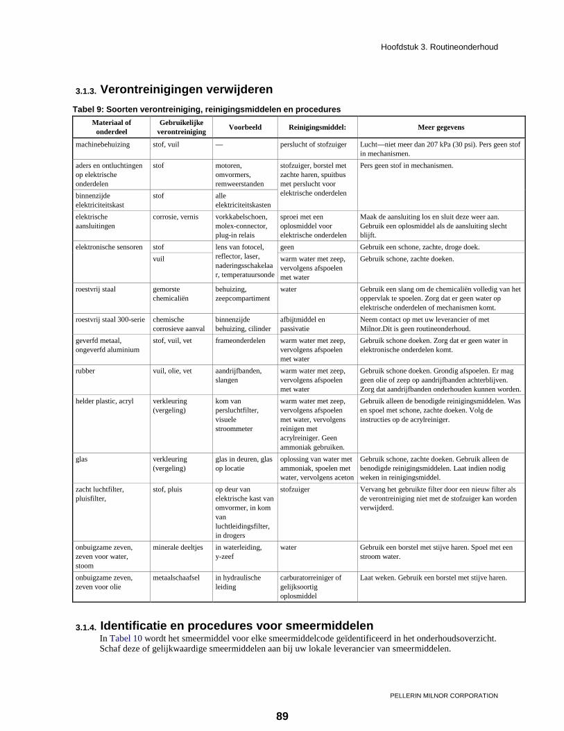
Hoofdstuk 3. Routineonderhoud
PELLERIN MILNOR CORPORATION
3.1.3. Verontreinigingen verwijderen Tabel 9: Soorten verontreiniging, reinigingsmiddelen en procedures
Materiaal of onderdeel
Gebruikelijke verontreiniging
Voorbeeld Reinigingsmiddel: Meer gegevens
machinebehuizing stof, vuil — perslucht of stofzuiger Lucht—niet meer dan 207 kPa (30 psi). Pers geen stof in mechanismen.
aders en ontluchtingen op elektrische onderdelen
stof motoren, omvormers, remweerstanden
stofzuiger, borstel met zachte haren, spuitbus met perslucht voor elektrische onderdelen
Pers geen stof in mechanismen.
binnenzijde elektriciteitskast
stof alle elektriciteitskasten
elektrische aansluitingen
corrosie, vernis vorkkabelschoen, molex-connector, plug-in relais
sproei met een oplosmiddel voor elektrische onderdelen
Maak de aansluiting los en sluit deze weer aan. Gebruik een oplosmiddel als de aansluiting slecht blijft.
elektronische sensoren stof lens van fotocel, reflector, laser, naderingsschakelaar, temperatuursonde
geen Gebruik een schone, zachte, droge doek. vuil warm water met zeep,
vervolgens afspoelen met water
Gebruik schone, zachte doeken.
roestvrij staal gemorste chemicaliën
behuizing, zeepcompartiment
water Gebruik een slang om de chemicaliën volledig van het oppervlak te spoelen. Zorg dat er geen water op elektrische onderdelen of mechanismen komt.
roestvrij staal 300-serie chemische corrosieve aanval
binnenzijde behuizing, cilinder
afbijtmiddel en passivatie
Neem contact op met uw leverancier of met Milnor.Dit is geen routineonderhoud.
geverfd metaal, ongeverfd aluminium
stof, vuil, vet frameonderdelen warm water met zeep, vervolgens afspoelen met water
Gebruik schone doeken. Zorg dat er geen water in elektronische onderdelen komt.
rubber vuil, olie, vet aandrijfbanden, slangen
warm water met zeep, vervolgens afspoelen met water
Gebruik schone doeken. Grondig afspoelen. Er mag geen olie of zeep op aandrijfbanden achterblijven. Zorg dat aandrijfbanden onderhouden kunnen worden.
helder plastic, acryl verkleuring (vergeling)
kom van persluchtfilter, visuele stroommeter
warm water met zeep, vervolgens afspoelen met water, vervolgens reinigen met acrylreiniger. Geen ammoniak gebruiken.
Gebruik alleen de benodigde reinigingsmiddelen. Was en spoel met schone, zachte doeken. Volg de instructies op de acrylreiniger.
glas verkleuring (vergeling)
glas in deuren, glas op locatie
oplossing van water met ammoniak, spoelen met water, vervolgens aceton
Gebruik schone, zachte doeken. Gebruik alleen de benodigde reinigingsmiddelen. Laat indien nodig weken in reinigingsmiddel.
zacht luchtfilter, pluisfilter,
stof, pluis op deur van elektrische kast van omvormer, in kom van luchtleidingsfilter, in drogers
stofzuiger Vervang het gebruikte filter door een nieuw filter als de verontreiniging niet met de stofzuiger kan worden verwijderd.
onbuigzame zeven, zeven voor water, stoom
minerale deeltjes in waterleiding, y-zeef
water Gebruik een borstel met stijve haren. Spoel met een stroom water.
onbuigzame zeven, zeven voor olie
metaalschaafsel in hydraulische leiding
carburatorreiniger of gelijksoortig oplosmiddel
Laat weken. Gebruik een borstel met stijve haren.
3.1.4. Identificatie en procedures voor smeermiddelen In Tabel 10 wordt het smeermiddel voor elke smeermiddelcode geïdentificeerd in het onderhoudsoverzicht. Schaf deze of gelijkwaardige smeermiddelen aan bij uw lokale leverancier van smeermiddelen.
89

Hoofdstuk 3. Routineonderhoud
PELLERIN MILNOR CORPORATION
Volg altijd de procedures in Sectie 3.1.4.1 wanneer u smering aanbrengt. Volg altijd de procedures in Sectie 3.1.4.2 wanneer u smering aanbrengt aan motoren.
WARRSCHUWING 20 : Risico op schade—Slechte smeermiddelen verlagen de levensduur van onderdelen. • Zorg dat alle apparatuur en fittingen waarmee smeermiddelen worden aangebracht schoon zijn. • Gebruik alleen de opgegeven smeermiddelen of gelijkwaardige smeermiddelen met dezelfde
specificaties. Tabel 10: Identificatie van smeermiddelen
Code Type Handelsnaam Toepassingsvoorbeeld EM smering Mobil Polyrex EM of zoals opgegeven
op de naamplaat van de motor motorlagers
EPLF2 smering Shell Alvania EP (LF) Type 2 lagers en bussen van aandrijfas, kogelverbindingen
30 olie Hoogwaardige motorolie SAE 30, 40 of 50 (niet-zuiverend, indien beschikbaar)
kleine lagerhuizen
3.1.4.1. Procedures voor vetspuit
WARRSCHUWING 21 : Risico op schade—Hydraulische druk kan sluitingen eruit drukken en vet in ongewenste gedeelten persen (voorbeeld: motorwikkelingen). • Gebruik een handmatige vetspuit. Een elektrische vetspuit geeft teveel druk. • Zorg dat u weet welke hoeveelheid smering de vetspuit elke cyclus (elke slag) geeft. • Bedien de vetspuit langzaam (10 tot 12 seconden voor een cyclus). • Breng niet meer dan de opgegeven hoeveelheid aan. Stop als er nieuw vet uit een afvoer of andere
opening komt. • Verwijder gemorst vet van banden en riemschijven. In de tabellen worden hoeveelheden vet gegeven in milliliters (ml) en fluid ounces (fl oz). U kunt ook cycli van de vetspuit gebruiken. Een cyclus is elke keer dat u de trekker overhaalt. Eén cyclus is gewoonlijk ongeveer 1,8 ml (0,06 fl oz). Uw vetspuit kan meer of minder leveren dan dat. Meet de uitvoer van uw vetspuit als volgt: 1. Zorg dat de vetspuit correct functioneert. 2. Bedien de vetspuit om vet in een kleine container te spuiten waarin millimeters of fluid ounces worden
aangegeven. Haal de hendel volledig en langzaam over. 3. Spuit voldoende vet om de hoeveelheid nauwkeurig te kunnen meten. Tel het aantal cycli van de
vetspuit (het aantal keren dat u de hendel overhaalt). 4. Bereken de hoeveelheid voor elke cyclus van de vetspuit.
Een voorbeeld: 59 ml / 64 cycli = 0,92 ml voor elke cyclus
Een voorbeeld: 2 fl oz / 64 cycli = 0,031 fl oz voor elke cyclus
3.1.4.2. Procedures voor motoren—Als een motor van uw apparaat geen smeernippels heeft, is er geen smeringonderhoud nodig. Als een motor van uw machine wel smeernippels heeft, is het nodig smering toe te voegen. Het interval is echter gewoonlijk langer dan voor ander onderhoud. In Tabel 11 vindt u de intervallen en hoeveelheden voor motorsmering voor motoren met de opgegeven framegroottes en snelheden. Deze gegevens vindt u op de naamplaat van de motor. Gebruik Tabel 7 in sectie 3.1.2 om de gegevens voor de motoren van uw machine vast te leggen.
90

Hoofdstuk 3. Routineonderhoud
PELLERIN MILNOR CORPORATION
Afbeelding 6: Voorwaarden voor motorsmeringonderhoud
Smeernippels en vetafvoer Smeernippels en vetuitlaat
Naamplaat motor Smeernippels, geen afvoer of uitlaat
Randschrift
1. Smeernippel 2. Vetafvoer. Niet verwijderen. 3. Plug van vetuitlaat. Eerst verwijderen. 4. RPM (motorsnelheid). Dit voorbeeld is 1465
RPM op 50 Hz en 1765 RPM op 60 Hz. 5. NEMA (IEC) framegrootte. Een voorbeeld:
256T .
WARRSCHUWING 22 : Risico op schade—U kunt vet in de wikkelingen persen en de motor verbranden als u de vetuitlaatpluggen niet verwijdert. • Als de motor vetuitlaatpluggen heeft, verwijdert u deze voordat u vet toevoegt. Als de motor
fittingen voor vetafvoer heeft, is het niet nodig deze te verwijderen. Breng vet aan als volgt: 1. Stel de machine in bedrijf of bedien de motor met handmatige functies tot deze warm is. 2. Sluit de stroom van de machine af. 3. Als de motor vetuitlaatpluggen heeft, verwijdert u deze. Zie verklaring betreffende voorzichtigheid
22 .
91

Hoofdstuk 3. Routineonderhoud
PELLERIN MILNOR CORPORATION
4. Breng vet EM (Tabel 10) aan, terwijl de motor stilstaat. Als de motor met de naamplaat in Afbeelding 6 werkt op 60 Hz, is de opgegeven hoeveelheid vet voor elke smeernippel 18,4 ml (0,65 fl oz).
5. Als de motor vetuitlaatpluggen heeft, stelt u de machine in bedrijf of gebruikt u handmatige functies om de motor twee uur te laten draaien. Plaats de uitlaatplug weer terug.
Tabel 11: Intervallen en hoeveelheden voor motorsmering Gebruik vet EM (Tabel 10) Op de motornaamplaat (zie Afbeelding
6) Interval Hoeveelheid
NEMA (IEC) framegrootte
RPM minder dan of gelijk aan
Jaren Uur Fluid
ounces ml
Maximaal 210 (132)
900 5.5 11000
0.34 9.5 1200 4.5 9000 1800 3 6000 3600 1.5 3000
>210 tot 280 (132 tot 180)
900 4.5 9000
0.65 18.4 1200 3.5 7000 1800 2.5 5000 3600 1 2000
>280 tot 360 (180 tot 200)
900 3.5 7000
0.87 24.6 1200 3 6000 1800 2 4000 3600 0.5 1000
>360 tot 5000 (200 tot 300)
900 2.5 5000
2.23 63.2 1200 2 4000 1800 1 2000 3600 0.5 1000
3.1.5. Onderhoudsonderdelen—machines en bedieningsgroep [Document BIUUUM10]
Supplement 1
Banden en riemschijven controleren
Controleer de transportbanden en riemschijven zoals hieronder worden uitgelegd.
Met de stroom afgesloten: • Kijk uit naar vuil, stof, olie en vet. Verwijder verontreinigingen. • Kijk uit naar schade aan de band zoals getoond in Afbeelding 7. • Kijk uit naar versleten riemschijven zoals getoond in Afbeelding 7.
Terwijl de machine in bedrijf is—Raak de machine niet aan. Kijk en luister: • Een band kan iets vibreren zonder dat dit schade veroorzaakt. Alleen als de vibratie sterk is, moet dit
worden gecorrigeerd. • Een band moet onder voldoende spanning staan om niet over de riemschijf te slippen tijdens gebruik.
Als de band slipt, kunt u dat gewoonlijk aan het geluid horen.
Onderdelen vervangen en de spanning aanpassen—De juiste afstelling is gewoonlijk zeer belangrijk voor de levensduur van onderdelen en het bedrijf van de machine. Uw Milnor-dealer kan dit doen. Als u weet hoe dit werk moet worden uitgevoerd (bijvoorbeeld banden en riemschijven op de juiste manier
92

Hoofdstuk 3. Routineonderhoud
PELLERIN MILNOR CORPORATION
uitlijnen), en u dit zelf wilt doen, neemt u contact op met uw dealer of Milnor voor de onderdeelnummers. Vervang versleten onderdelen voordat u de spanning verandert.
• Machines die voorzien zijn van stangen met volledig schroefdraad en moeren om de positie van de motorbasis vast te zetten—Draai de moeren op de stangen om de spanning aan te passen. Draai de moeren aan.
• Machines die een veer hebben voor het instellen van de spanning op de motorbasis—Gebruik de metalen buis die met de machine is meegeleverd. Plaats de buis op de stang waaraan de veer is bevestigd of verwijderd de buis om de spanning groter of kleiner te maken. Vervang de veer indien nodig.
Afbeelding 7: Toestanden van band en riemschijf om naar uit te kijken. Zie Supplement 1.
Soorten schade aan band Een versleten riemschijf vinden
Randschrift
1. Gebroken koord—schade door een scherp object. 2. Barsten—band is te groot voor de riemschijf. 3. Glinsterende zijkanten—olie of vet op de band. 4. De lagen van de band raken los van elkaar—Olie
of vet. 5. Strepen op de zijkanten—vuil, deeltjes. 6. Fout: de riemschijf is te versleten. 7. Goed: de band raakt alleen de zijkanten. U kunt
een dunne strook papier in de ruimte tussen de band en de riemschijf steken.
8. Ruimte .
93

Hoofdstuk 3. Routineonderhoud
PELLERIN MILNOR CORPORATION
Afbeelding 8: Elektriciteitskast en omvormer. Dit zijn voorbeelden. Uw machine kan er anders uitzien.
Was-/extractiemachine 30022X_ Was-/extractiemachine 48040F_ CBW-wastunnel 76039
Randschrift
1. Luchtfilter 2. Ventilator op deur elektriciteitskast. Tip: houd een wimpel voor de ventilator om te controleren of deze
werkt. 3. Koelbladen en ontluchtingen van omvormer. Zie verklaring betreffende voorzichtigheid 23 . 4. Remweerstand, indien van toepassing.
.
WARRSCHUWING 23 : Risico op schade—Zonder voldoende luchtcirculatie verbrandt de omvormer. • Houd ventilatoren, filter, ontluchtingsopeningen en remweerstanden schoon.
Afbeelding 9: Chemische inlaatverdelers voor pompsystemen voor chemicaliën. Zie verklaring betreffende voorzichtigheid 24 . Dit zijn voorbeelden. Uw machine kan er anders uitzien.
36026V7J 60044WP2 76039CBW
.
WARRSCHUWING 24 : Risico op corrosieschade aan de machine en de goederen— • Sluit chemische buizen alleen aan op chemische verdelerinlaten. • Stop lekkages. Verwijder gelekte stoffen van oppervlakken. • Neem contact op met uw leverancier of met Milnor als u corrosieschade opmerkt.
94

Hoofdstuk 3. Routineonderhoud
PELLERIN MILNOR CORPORATION
WARRSCHUWING 25 : Risico op letsel en schade—Chemicaliën kunnen op de grond en op oppervlakken van de machine terechtkomen als de waterdruk te hoog is. • Controleer of de druk is ingesteld volgens het onderhoudsoverzicht.
Afbeelding 10: Zeepgoot en optioneel zeepcompartiment met 3 kamers
Zeepcompartiment Kleppen in klepcompartiment Zeepgoot
Randschrift
1. Laat geen resten van chemicaliën achter op roestvrijstalen oppervlakken.
2. Klepcompartiment 3. Filter (een van drie)
.
95

Hoofdstuk 3. Routineonderhoud
PELLERIN MILNOR CORPORATION
Afbeelding 11: Luchtslang voor de waterpeilsensor. Dit zijn voorbeelden. Uw machine kan er anders uitzien.
Was-/extractiemachine 30022T5E Was-/extractiemachine 42044SP2 Was-/extractiemachine 36030F8_
Was-/extractiemachine 30022V6J
Randschrift 1. Peilschakelaars 2. Drukomzetter 3. Luchtslang. Zie verklaring
betreffende voorzichtigheid 26 .
4. Luchtkamer .
WARRSCHUWING 26 : Risico op storingen—De peilsensor moet correcte gegevens leveren. • Houd de aansluitslang of -buis vrij van blokkades en lekkages. • Zorg dat de aansluitingen stevig vast zitten.
Afbeelding 12: Stoominlaatzeef. Dit zijn voorbeelden. Uw machine kan er anders uitzien.
Was-/extractiemachine 42044SP2 Wastunnel 76039CBW Randschrift
1. Stoomzeef. Haal de stoomdruk er af voordat u de plug verwijdert. Zie verklaring betreffende waarschuwingen 27 .
2. Stoomklep
.
WAARSCHUWING 27 : Gevaar op ernstig letsel—U kunt per ongeluk stoom onder druk laten ontsnappen. • Sluit de externe afsluitklep en laat de resterende druk ontsnappen voordat u onderhoud uitvoert.
96

Hoofdstuk 3. Routineonderhoud
PELLERIN MILNOR CORPORATION
Afbeelding 13: Inlaatzeven perslucht. Dit zijn voorbeelden. Uw machine kan er anders uitzien.
T-zeef. Aan de buitenkant van het machineframe op sommige
modellen.
T-zeef. Aan de binnenkant van het machineframe op sommige
modellen.
Y-zeef. Gebruikt op sommige modellen.
Randschrift 1. Zie verklaring betreffende voorzichtigheid 28 . Verwijder
de plug om de zeef te verwijderen. 2. Perslucht in.
.
WARRSCHUWING 28 : Risico op letsel en schade— • Sluit de externe afsluitklep en laat de resterende druk ontsnappen voordat u onderhoud uitvoert.
3.1.6. Onderhoudsonderdelen—Grote extractiemachines [Document BIWUUM03]
Afbeelding 14: Olie-onderhoudsgedeelten voor lagers. A 30022T5E wordt weergegeven. Uw machine kan er anders uitzien.
Weergaven van de onderhoudsgedeelten Randschrift
1. Olietapopening. Zorg er bij het verwijderen van de gebruikte olie voor dat er geen olie op de motor of andere onderdelen terecht komt.
2. Olievulleiding en stop. Zorg ervoor dat er geen nieuwe olie op de onderdelen in de console terecht komt.
3. Behuizing aftappoort 4. Aftapleiding holte
verzegeling. Verwijder de verontreinigingen die uit de leiding lopen.
.
— Einde BIUUUM09 —
97