2755-833, ds/dd ser.b bar code decoders user...
TRANSCRIPT

UserManual
DS/DD Series BEnhanced BarCode Decoders
(Bulletin 2755)
Allen-Bradley

Because of the variety of uses for the products described in thispublication, those responsible for the application and use of thiscontrol equipment must satisfy themselves that all necessary stepshave been taken to assure that each application and use meets allperformance and safety requirements, including any applicable laws,regulations, codes and standards.
The illustrations, charts, sample programs and layout examplesshown in this guide are intended solely for purposes of example.Since there are many variables and requirements associated with anyparticular installation, Allen-Bradley does not assume responsibilityor liability (to include intellectual property liability) for actual usebased upon the examples shown in this publication.
Allen-Bradley publication SGI-1.1, Safety Guidelines for theApplication, Installation, and Maintenance of Solid-State Control(available from your local Allen-Bradley office), describes someimportant differences between solid-state equipment andelectromechanical devices that should be taken into considerationwhen applying products such as those described in this publication.
Reproduction of the contents of this copyrighted publication, inwhole or in part, without written permission of Allen-BradleyCompany, Inc., is prohibited.
Throughout this manual we use notes to make you aware of safetyconsiderations:
!ATTENTION: Identifies information about practicesor circumstances that can lead to personal injury ordeath, property damage or economic loss.
Attention statements help you to:
• identify a hazard
• avoid the hazard
• recognize the consequences
Important: Identifies information that is critical for successfulapplication and understanding of the product.
Important UserInformation

Table of Contents toc-i
Publication 2755-833
Chapter 1
Chapter Objectives 1–1. . . . . . . . . . . . . . . . . . . . . . . . . . . . . . . . . . What the Package Includes 1–1. . . . . . . . . . . . . . . . . . . . . . . . . . . . Contents of Manual 1–2. . . . . . . . . . . . . . . . . . . . . . . . . . . . . . . . . . What You Need to Know 1–3. . . . . . . . . . . . . . . . . . . . . . . . . . . . . . Terminology 1–3. . . . . . . . . . . . . . . . . . . . . . . . . . . . . . . . . . . . . . . Conventions Used 1–3. . . . . . . . . . . . . . . . . . . . . . . . . . . . . . . . . . . Related Publications 1–4. . . . . . . . . . . . . . . . . . . . . . . . . . . . . . . . .
Chapter 2
Chapter Objectives 2–1. . . . . . . . . . . . . . . . . . . . . . . . . . . . . . . . . . NEMA Type Enclosures 2–1. . . . . . . . . . . . . . . . . . . . . . . . . . . . . . . Scanner Ports 2–1. . . . . . . . . . . . . . . . . . . . . . . . . . . . . . . . . . . . . . Power Supply 2–2. . . . . . . . . . . . . . . . . . . . . . . . . . . . . . . . . . . . . . LED Indicators 2–3. . . . . . . . . . . . . . . . . . . . . . . . . . . . . . . . . . . . . . LCD Display 2–4. . . . . . . . . . . . . . . . . . . . . . . . . . . . . . . . . . . . . . . AUX Port 2–4. . . . . . . . . . . . . . . . . . . . . . . . . . . . . . . . . . . . . . . . .
Decoder Configuration 2–4. . . . . . . . . . . . . . . . . . . . . . . . . . . . . . Manual Data Entry 2–4. . . . . . . . . . . . . . . . . . . . . . . . . . . . . . . . .
Host Port 2–5. . . . . . . . . . . . . . . . . . . . . . . . . . . . . . . . . . . . . . . . . Power Connector and On/Off Switch 2–5. . . . . . . . . . . . . . . . . . . . . . Memory Backup 2–5. . . . . . . . . . . . . . . . . . . . . . . . . . . . . . . . . . . . Discrete I/O Modules 2–5. . . . . . . . . . . . . . . . . . . . . . . . . . . . . . . . . Decoder Options (NEMA Type 1 Decoders) 2–7. . . . . . . . . . . . . . . . .
Power Cords 2–7. . . . . . . . . . . . . . . . . . . . . . . . . . . . . . . . . . . . . Decoder Options (NEMA Type 4 Decoders) 2–8. . . . . . . . . . . . . . . . .
Power Cords 2–8. . . . . . . . . . . . . . . . . . . . . . . . . . . . . . . . . . . . . Input/Output Modules 2–9. . . . . . . . . . . . . . . . . . . . . . . . . . . . . . . Replacement Fuses (for decoders with I/O Module Board options) 2–9I/O Module Board Options (available when ordering either the NEMA Type
1 or Type 4 decoder) 2–9. . . . . . . . . . . . . . . . . . . . . . . . . . . . . LCD Display 2–10. . . . . . . . . . . . . . . . . . . . . . . . . . . . . . . . . . . . .
Scanners 2–11. . . . . . . . . . . . . . . . . . . . . . . . . . . . . . . . . . . . . . . . . Decoder Accessories 2–11. . . . . . . . . . . . . . . . . . . . . . . . . . . . . . . . .
Configuration and Cable Group Selector 2–11. . . . . . . . . . . . . . . . . Cable Selection Guide 2–12. . . . . . . . . . . . . . . . . . . . . . . . . . . . . . Package Detectors for Scanners 2–13. . . . . . . . . . . . . . . . . . . . . . . Communication Cable and Connector Kit 2–13. . . . . . . . . . . . . . . . .
Chapter 3
Chapter Objectives 3–1. . . . . . . . . . . . . . . . . . . . . . . . . . . . . . . . . . Function of Decoder 3–1. . . . . . . . . . . . . . . . . . . . . . . . . . . . . . . . . . Bar Code Symbologies 3–1. . . . . . . . . . . . . . . . . . . . . . . . . . . . . . . . Configuration Options 3–1. . . . . . . . . . . . . . . . . . . . . . . . . . . . . . . .
Using this Manual
Decoder Features
Overview of DecoderOperations

Table of Contentstoc-ii
Publication 2755-833
Configuration Screens 3–2. . . . . . . . . . . . . . . . . . . . . . . . . . . . . . Host Commands 3–2. . . . . . . . . . . . . . . . . . . . . . . . . . . . . . . . . .
Stand-alone Operation 3–2. . . . . . . . . . . . . . . . . . . . . . . . . . . . . . . . Host Operation 3–3. . . . . . . . . . . . . . . . . . . . . . . . . . . . . . . . . . . . .
Programmable Logic Controllers (PLC) 3–3. . . . . . . . . . . . . . . . . . Host Computers 3–5. . . . . . . . . . . . . . . . . . . . . . . . . . . . . . . . . .
Types of Memory 3–5. . . . . . . . . . . . . . . . . . . . . . . . . . . . . . . . . . . . Operating Memory 3–6. . . . . . . . . . . . . . . . . . . . . . . . . . . . . . . . . Storage Memory 3–6. . . . . . . . . . . . . . . . . . . . . . . . . . . . . . . . . . Memory Contents at Startup 3–7. . . . . . . . . . . . . . . . . . . . . . . . . .
Decoder Operating Modes 3–8. . . . . . . . . . . . . . . . . . . . . . . . . . . . . Scanning Modes 3–8. . . . . . . . . . . . . . . . . . . . . . . . . . . . . . . . . . Decode Modes 3–8. . . . . . . . . . . . . . . . . . . . . . . . . . . . . . . . . . . Sending Data to Host – Speed vs. Timing 3–9. . . . . . . . . . . . . . . .
Chapter 4
Chapter Objectives 4–1. . . . . . . . . . . . . . . . . . . . . . . . . . . . . . . . . . Power Requirements 4–1. . . . . . . . . . . . . . . . . . . . . . . . . . . . . . . . . Electrical Recommendations 4–1. . . . . . . . . . . . . . . . . . . . . . . . . . . Grounding 4–2. . . . . . . . . . . . . . . . . . . . . . . . . . . . . . . . . . . . . . . . . Replacing LED Label 4–2. . . . . . . . . . . . . . . . . . . . . . . . . . . . . . . . . Mounting the Decoder 4–3. . . . . . . . . . . . . . . . . . . . . . . . . . . . . . . . Installing Power Cord 4–4. . . . . . . . . . . . . . . . . . . . . . . . . . . . . . . . . Quick Start for DS/DD Decoder Configuration and Scanner Setup 4–6.
Connect AUX Terminal 4–6. . . . . . . . . . . . . . . . . . . . . . . . . . . . . . Set Communication Parameters 4–6. . . . . . . . . . . . . . . . . . . . . . . Apply Power and Select Language 4–6. . . . . . . . . . . . . . . . . . . . . Select CRT Type 4–7. . . . . . . . . . . . . . . . . . . . . . . . . . . . . . . . . . Select Operations 4–8. . . . . . . . . . . . . . . . . . . . . . . . . . . . . . . . . Set Symbology Parameters 4–9. . . . . . . . . . . . . . . . . . . . . . . . . . Configure Scanner(s) 4–10. . . . . . . . . . . . . . . . . . . . . . . . . . . . . . . Customize As Required 4–15. . . . . . . . . . . . . . . . . . . . . . . . . . . . .
Connecting the AUX Terminal 4–15. . . . . . . . . . . . . . . . . . . . . . . . . . . Connecting the Host Device 4–16. . . . . . . . . . . . . . . . . . . . . . . . . . . . Installing I/O Modules 4–19. . . . . . . . . . . . . . . . . . . . . . . . . . . . . . . . . Connecting I/O Modules to External Devices 4–20. . . . . . . . . . . . . . . . Wiring I/O Modules 4–20. . . . . . . . . . . . . . . . . . . . . . . . . . . . . . . . . . Installing Conduit Hubs/NEMA Type 4 Decoder 4–22. . . . . . . . . . . . . .
Conduit Holes 4–22. . . . . . . . . . . . . . . . . . . . . . . . . . . . . . . . . . . . Conduit Connections 4–22. . . . . . . . . . . . . . . . . . . . . . . . . . . . . . .
Chapter 5
Chapter Objectives 5–1. . . . . . . . . . . . . . . . . . . . . . . . . . . . . . . . . . Connect and Set Up AUX Terminal 5–1. . . . . . . . . . . . . . . . . . . . . . . AUX Terminal Selector 5–1. . . . . . . . . . . . . . . . . . . . . . . . . . . . . . . .
Installing the Decoder
Introduction to AUXTerminal Configuration

Table of Contents toc-iii
Publication 2755-833
Getting Started 5–2. . . . . . . . . . . . . . . . . . . . . . . . . . . . . . . . . . . . . Configuration Functions 5–4. . . . . . . . . . . . . . . . . . . . . . . . . . . . . . . Editing Conventions 5–5. . . . . . . . . . . . . . . . . . . . . . . . . . . . . . . . . .
Highlight 5–6. . . . . . . . . . . . . . . . . . . . . . . . . . . . . . . . . . . . . . . . Moving Around the Screen 5–6. . . . . . . . . . . . . . . . . . . . . . . . . . . Field Types 5–7. . . . . . . . . . . . . . . . . . . . . . . . . . . . . . . . . . . . . .
Select Field 5–7. . . . . . . . . . . . . . . . . . . . . . . . . . . . . . . . . . . . Edit Field 5–7. . . . . . . . . . . . . . . . . . . . . . . . . . . . . . . . . . . . . . Select/Edit Numeric Field 5–7. . . . . . . . . . . . . . . . . . . . . . . . . .
Changing Fields 5–7. . . . . . . . . . . . . . . . . . . . . . . . . . . . . . . . . . Audible Beep 5–9. . . . . . . . . . . . . . . . . . . . . . . . . . . . . . . . . . . . . Help Line 5–9. . . . . . . . . . . . . . . . . . . . . . . . . . . . . . . . . . . . . . .
Select Mode 5–9. . . . . . . . . . . . . . . . . . . . . . . . . . . . . . . . . . . Edit Mode 5–9. . . . . . . . . . . . . . . . . . . . . . . . . . . . . . . . . . . . .
Command Line 5–10. . . . . . . . . . . . . . . . . . . . . . . . . . . . . . . . . . . Command Summary 5–10. . . . . . . . . . . . . . . . . . . . . . . . . . . . . . .
Chapter 6
Configure Symbology 6–1. . . . . . . . . . . . . . . . . . . . . . . . . . . . . . . . . Code 39 6–2. . . . . . . . . . . . . . . . . . . . . . . . . . . . . . . . . . . . . . . . Code 39 Specific Lengths 6–2. . . . . . . . . . . . . . . . . . . . . . . . . . . . Code 39 Check Character 6–3. . . . . . . . . . . . . . . . . . . . . . . . . . . Include Code 39 Check Character 6–3. . . . . . . . . . . . . . . . . . . . . . Interleaved 2-of-5 6–3. . . . . . . . . . . . . . . . . . . . . . . . . . . . . . . . . Interleaved 2-of-5 Specific Lengths 6–3. . . . . . . . . . . . . . . . . . . . . Interleaved 2-of-5 Check Character 6–4. . . . . . . . . . . . . . . . . . . . . Include Interleaved 2-of-5 Check Character 6–4. . . . . . . . . . . . . . . Interleaved 2-of-5 Guard Bars 6–4. . . . . . . . . . . . . . . . . . . . . . . . . Codabar 6–5. . . . . . . . . . . . . . . . . . . . . . . . . . . . . . . . . . . . . . . . Codabar Specific Lengths 6–5. . . . . . . . . . . . . . . . . . . . . . . . . . . . Codabar Check Character 6–5. . . . . . . . . . . . . . . . . . . . . . . . . . . Include Codabar Check Character 6–5. . . . . . . . . . . . . . . . . . . . . . Code 128 6–6. . . . . . . . . . . . . . . . . . . . . . . . . . . . . . . . . . . . . . . Code 128 Specific Lengths 6–6. . . . . . . . . . . . . . . . . . . . . . . . . . . Code 128 FNC1 Character 6–7. . . . . . . . . . . . . . . . . . . . . . . . . . . UPC-A 6–7. . . . . . . . . . . . . . . . . . . . . . . . . . . . . . . . . . . . . . . . . UPC-A Supplements 6–7. . . . . . . . . . . . . . . . . . . . . . . . . . . . . . . UPC-E 6–8. . . . . . . . . . . . . . . . . . . . . . . . . . . . . . . . . . . . . . . . . UPC-E Supplements 6–8. . . . . . . . . . . . . . . . . . . . . . . . . . . . . . . Expand UPC-E 6–9. . . . . . . . . . . . . . . . . . . . . . . . . . . . . . . . . . . EAN-8 6–9. . . . . . . . . . . . . . . . . . . . . . . . . . . . . . . . . . . . . . . . . EAN-8 Supplements 6–9. . . . . . . . . . . . . . . . . . . . . . . . . . . . . . . EAN-13 6–10. . . . . . . . . . . . . . . . . . . . . . . . . . . . . . . . . . . . . . . . . EAN-13 Supplements 6–10. . . . . . . . . . . . . . . . . . . . . . . . . . . . . . . Enable Pharma-Code Symbology (Pharma-Code Decoders Only) 6–10
Configuration: Symbology

Table of Contentstoc-iv
Publication 2755-833
Quiet Zone Ratio (All Decoders) 6–11. . . . . . . . . . . . . . . . . . . . . . . Space Tolerance (Pharma-Code Decoders Only) 6–12. . . . . . . . . . . Bar Tolerance (Pharma-Code Decoders Only) 6–12. . . . . . . . . . . . . Minimum Number of Bars (Pharma-Code Decoders Only) 6–13. . . . . Decode Direction (A or B) (Pharma-Code Decoders Only) 6–14. . . . . Wide to Narrow Bar Ratio (Pharma-Code Decoders Only) 6–14. . . . . Code Verification List (Pharma-Code Decoders Only) 6–15. . . . . . . .
Chapter 7
Scanner Control, Primary Match Code Table, Discrete I/O 7–1. . . . . . . Scanner A Control Parameters 7–1. . . . . . . . . . . . . . . . . . . . . . . .
Laser Light (Scanners A and B) 7–2. . . . . . . . . . . . . . . . . . . . . Decode Mode 7–2. . . . . . . . . . . . . . . . . . . . . . . . . . . . . . . . . . No-Read Timer 7–4. . . . . . . . . . . . . . . . . . . . . . . . . . . . . . . . . Inter-Scan Timer 7–5. . . . . . . . . . . . . . . . . . . . . . . . . . . . . . . . Capture Count 7–6. . . . . . . . . . . . . . . . . . . . . . . . . . . . . . . . . . Symbols / Scan 7–7. . . . . . . . . . . . . . . . . . . . . . . . . . . . . . . . . Symbols/Package 7–8. . . . . . . . . . . . . . . . . . . . . . . . . . . . . . . Match Complete 7–8. . . . . . . . . . . . . . . . . . . . . . . . . . . . . . . .
Scanner B Control Parameters 7–8. . . . . . . . . . . . . . . . . . . . . . . . Laser Light 7–9. . . . . . . . . . . . . . . . . . . . . . . . . . . . . . . . . . . . Decode Mode 7–9. . . . . . . . . . . . . . . . . . . . . . . . . . . . . . . . . . Trigger Timeout 7–11. . . . . . . . . . . . . . . . . . . . . . . . . . . . . . . . .
Package Detect Input Parameters 7–11. . . . . . . . . . . . . . . . . . . . . . Package Detect Input A Filter 7–11. . . . . . . . . . . . . . . . . . . . . . . . .
Package Detect Input A Sense 7–12. . . . . . . . . . . . . . . . . . . . . . Package Detect Input B Filter 7–12. . . . . . . . . . . . . . . . . . . . . . . Package Detect Input B Sense 7–13. . . . . . . . . . . . . . . . . . . . . .
Primary Match Table Parameters 7–13. . . . . . . . . . . . . . . . . . . . . . Symbology (1 - 8) 7–14. . . . . . . . . . . . . . . . . . . . . . . . . . . . . . . Match Code String (1 - 8) 7–14. . . . . . . . . . . . . . . . . . . . . . . . . .
Discrete I/O Parameters 7–15. . . . . . . . . . . . . . . . . . . . . . . . . . . . . Output State 7–15. . . . . . . . . . . . . . . . . . . . . . . . . . . . . . . . . . . Source 7–16. . . . . . . . . . . . . . . . . . . . . . . . . . . . . . . . . . . . . . . Output Condition 7–16. . . . . . . . . . . . . . . . . . . . . . . . . . . . . . . . Output Duration 7–21. . . . . . . . . . . . . . . . . . . . . . . . . . . . . . . . .
Chapter 8
Extended Match Table 8–1. . . . . . . . . . . . . . . . . . . . . . . . . . . . . . . . Screen Status 8–2. . . . . . . . . . . . . . . . . . . . . . . . . . . . . . . . . . . . Status of Counter Set 8–3. . . . . . . . . . . . . . . . . . . . . . . . . . . . . . . Mode 8–3. . . . . . . . . . . . . . . . . . . . . . . . . . . . . . . . . . . . . . . . . . Source 8–5. . . . . . . . . . . . . . . . . . . . . . . . . . . . . . . . . . . . . . . . . Symbology 8–5. . . . . . . . . . . . . . . . . . . . . . . . . . . . . . . . . . . . . . Match Pattern String 8–6. . . . . . . . . . . . . . . . . . . . . . . . . . . . . . .
Configuration: ScannerControl, Primary MatchTable, Discrete I/O
Configuration: ExtendedMatch Table and Counters

Table of Contents toc-v
Publication 2755-833
Count 8–6. . . . . . . . . . . . . . . . . . . . . . . . . . . . . . . . . . . . . . . . . . Loading 8–7. . . . . . . . . . . . . . . . . . . . . . . . . . . . . . . . . . . . . . . . Output Duration 8–9. . . . . . . . . . . . . . . . . . . . . . . . . . . . . . . . . . .
Chapter 9
AUX and LCD Display Parameters 9–1. . . . . . . . . . . . . . . . . . . . . . . Display Data 9–1. . . . . . . . . . . . . . . . . . . . . . . . . . . . . . . . . . . . . Message Format 9–2. . . . . . . . . . . . . . . . . . . . . . . . . . . . . . . . . . Scroll LCD 9–3. . . . . . . . . . . . . . . . . . . . . . . . . . . . . . . . . . . . . . Position: Bar Code Strings 9–4. . . . . . . . . . . . . . . . . . . . . . . . . . . Position: Decoder Performance 9–4. . . . . . . . . . . . . . . . . . . . . . . Position: Package Counter 9–4. . . . . . . . . . . . . . . . . . . . . . . . . . Position: Symbols Not Read Counter 9–5. . . . . . . . . . . . . . . . . . . Position: Primary Counters 9–5. . . . . . . . . . . . . . . . . . . . . . . . . . Displaying Host Messages 9–5. . . . . . . . . . . . . . . . . . . . . . . . . . .
ASCII Command 9–6. . . . . . . . . . . . . . . . . . . . . . . . . . . . . . . . PCCC Command 9–6. . . . . . . . . . . . . . . . . . . . . . . . . . . . . . . . How Scrolling Affects the Display of Host Messages 9–7. . . . . . .
LCD Display Examples 9–8. . . . . . . . . . . . . . . . . . . . . . . . . . . . . . Adjusting Contrast of LCD Display 9–10. . . . . . . . . . . . . . . . . . . . . . . .
AUX Terminal Display Examples 9–10. . . . . . . . . . . . . . . . . . . . . . .
Chapter 10
Introduction to Host Message Replacement Rules 10–1. . . . . . . . . . . . Symbols vs. Host Message Fields 10–2. . . . . . . . . . . . . . . . . . . . . . Introduction to Host Message Replacement Rules 10–2. . . . . . . . . . Metacharacters 10–3. . . . . . . . . . . . . . . . . . . . . . . . . . . . . . . . . . . Processing Order 10–7. . . . . . . . . . . . . . . . . . . . . . . . . . . . . . . . . .
Configuration Parameters 10–8. . . . . . . . . . . . . . . . . . . . . . . . . . . . . . Source 10–8. . . . . . . . . . . . . . . . . . . . . . . . . . . . . . . . . . . . . . . . . Symbology 10–9. . . . . . . . . . . . . . . . . . . . . . . . . . . . . . . . . . . . . . Symbol Number 10–9. . . . . . . . . . . . . . . . . . . . . . . . . . . . . . . . . . . Find String Containing 10–11. . . . . . . . . . . . . . . . . . . . . . . . . . . . . . Replace Entire String With 10–12. . . . . . . . . . . . . . . . . . . . . . . . . . . Minimum Field Length 10–12. . . . . . . . . . . . . . . . . . . . . . . . . . . . . . Alignment 10–13. . . . . . . . . . . . . . . . . . . . . . . . . . . . . . . . . . . . . . . Fill Character 10–13. . . . . . . . . . . . . . . . . . . . . . . . . . . . . . . . . . . . . Host Message Field Number 10–13. . . . . . . . . . . . . . . . . . . . . . . . . . Assembling a Host Message 10–14. . . . . . . . . . . . . . . . . . . . . . . . . . Examples 10–15. . . . . . . . . . . . . . . . . . . . . . . . . . . . . . . . . . . . . . .
Example 1: Sorting by Data Source 10–15. . . . . . . . . . . . . . . . . . Example 2: Identifying the Source of Data 10–15. . . . . . . . . . . . . . Example 3: Sorting by Symbology 10–16. . . . . . . . . . . . . . . . . . . Example 4: Sorting by Symbol Number 10–16. . . . . . . . . . . . . . . . Example 5: Sorting Symbols by Data Identifiers 10–17. . . . . . . . . .
Configuration: AUX andLCD Display Parameters
Configuration: HostMessage ReplacementRules
Table of Contentstoc-vi
Publication 2755-833
Example 6: Sorting by Unique Characters and/or Strings 10–18. . . Example 7: Stripping Unwanted Characters 10–18. . . . . . . . . . . . Example 8: Stripping Unwanted Characters 10–19. . . . . . . . . . . . Example 9: Substituting Characters Within a String 10–19. . . . . . .
Chapter 11
Host Message Format 11–1. . . . . . . . . . . . . . . . . . . . . . . . . . . . . . . . Introduction to Host Message Format 11–1. . . . . . . . . . . . . . . . . . . . .
Bar Code Host Message Format 11–2. . . . . . . . . . . . . . . . . . . . . . . Host Message Parameters 11–4. . . . . . . . . . . . . . . . . . . . . . . . . . . . .
Start Character 11–4. . . . . . . . . . . . . . . . . . . . . . . . . . . . . . . . . . . Source Identifier for AUX, A, and B 11–4. . . . . . . . . . . . . . . . . . . . . Header Message 11–5. . . . . . . . . . . . . . . . . . . . . . . . . . . . . . . . . . Field Delimiter 11–5. . . . . . . . . . . . . . . . . . . . . . . . . . . . . . . . . . . . Number of Fields in Message 11–5. . . . . . . . . . . . . . . . . . . . . . . . . Send Symbology 11–6. . . . . . . . . . . . . . . . . . . . . . . . . . . . . . . . . . Send Package Count 11–6. . . . . . . . . . . . . . . . . . . . . . . . . . . . . . . Send Bar Code Strings 11–6. . . . . . . . . . . . . . . . . . . . . . . . . . . . . . Send Decoder Performance 11–7. . . . . . . . . . . . . . . . . . . . . . . . . . End Message 11–7. . . . . . . . . . . . . . . . . . . . . . . . . . . . . . . . . . . . Default No-Read Message 11–7. . . . . . . . . . . . . . . . . . . . . . . . . . . No-Read Replacement Strings 11–8. . . . . . . . . . . . . . . . . . . . . . . .
Chapter 12
Host Communications 12–1. . . . . . . . . . . . . . . . . . . . . . . . . . . . . . . . Baud Rate 12–2. . . . . . . . . . . . . . . . . . . . . . . . . . . . . . . . . . . . . . . Bits/Char 12–2. . . . . . . . . . . . . . . . . . . . . . . . . . . . . . . . . . . . . . . . Parity 12–2. . . . . . . . . . . . . . . . . . . . . . . . . . . . . . . . . . . . . . . . . . Host Protocol 12–3. . . . . . . . . . . . . . . . . . . . . . . . . . . . . . . . . . . . Device Address 12–3. . . . . . . . . . . . . . . . . . . . . . . . . . . . . . . . . . . ACK Character 12–4. . . . . . . . . . . . . . . . . . . . . . . . . . . . . . . . . . . NAK Character 12–4. . . . . . . . . . . . . . . . . . . . . . . . . . . . . . . . . . . Start Scan Character 12–5. . . . . . . . . . . . . . . . . . . . . . . . . . . . . . . Stop Scan Character 12–5. . . . . . . . . . . . . . . . . . . . . . . . . . . . . . . Large Buffer 12–6. . . . . . . . . . . . . . . . . . . . . . . . . . . . . . . . . . . . . Send Message to Host 12–6. . . . . . . . . . . . . . . . . . . . . . . . . . . . . . Transmission Check 12–7. . . . . . . . . . . . . . . . . . . . . . . . . . . . . . .
Chapter 13
Chapter Objectives 13–1. . . . . . . . . . . . . . . . . . . . . . . . . . . . . . . . . . Supported Terminals 13–1. . . . . . . . . . . . . . . . . . . . . . . . . . . . . . . . . AUX Terminal Configuration 13–2. . . . . . . . . . . . . . . . . . . . . . . . . . . .
Enable Keyboard Entry 13–2. . . . . . . . . . . . . . . . . . . . . . . . . . . . . Confirm Entry 13–3. . . . . . . . . . . . . . . . . . . . . . . . . . . . . . . . . . . .
Configuration: HostMessage Format
Configuration: HostCommunications
Configuration: AUXTerminal Data Entry

Table of Contents toc-vii
Publication 2755-833
AUX Data Format 13–4. . . . . . . . . . . . . . . . . . . . . . . . . . . . . . . . . Rubout Character 13–4. . . . . . . . . . . . . . . . . . . . . . . . . . . . . . . . . Echo To Terminal 13–4. . . . . . . . . . . . . . . . . . . . . . . . . . . . . . . . . . Size of Display 13–5. . . . . . . . . . . . . . . . . . . . . . . . . . . . . . . . . . . Default Prompt Message 13–5. . . . . . . . . . . . . . . . . . . . . . . . . . . .
Switching to Manual Data Entry Mode 13–5. . . . . . . . . . . . . . . . . . . . . Internal Selector 13–6. . . . . . . . . . . . . . . . . . . . . . . . . . . . . . . . . .
Internal Selector (AUX Terminal Jumper) 13–6. . . . . . . . . . . . . . . External Selector 13–6. . . . . . . . . . . . . . . . . . . . . . . . . . . . . . . . . .
Data Entry and Display Operations 13–7. . . . . . . . . . . . . . . . . . . . . . . Displaying Data at the AUX Terminal 13–7. . . . . . . . . . . . . . . . . . . . . .
Displaying Host Messages 13–8. . . . . . . . . . . . . . . . . . . . . . . . . . . Processing No-Reads 13–8. . . . . . . . . . . . . . . . . . . . . . . . . . . . . .
Using ASCII and PCCC Commands 13–10. . . . . . . . . . . . . . . . . . . . . . ASCII Commands 13–10. . . . . . . . . . . . . . . . . . . . . . . . . . . . . . . . .
Format of Manually Entered Data 13–11. . . . . . . . . . . . . . . . . . . . PCCC Commands 13–11. . . . . . . . . . . . . . . . . . . . . . . . . . . . . . . . .
Chapter 14
Chapter Objectives 14–1. . . . . . . . . . . . . . . . . . . . . . . . . . . . . . . . . . Connect and Set Up AUX Terminal 14–1. . . . . . . . . . . . . . . . . . . . . . . Display Bar Code Strings 14–2. . . . . . . . . . . . . . . . . . . . . . . . . . . . . . Display Status and Primary Counters 14–3. . . . . . . . . . . . . . . . . . . . .
Resetting the Counters 14–5. . . . . . . . . . . . . . . . . . . . . . . . . . . . . . Restart System 14–5. . . . . . . . . . . . . . . . . . . . . . . . . . . . . . . . . . . . . Select Language 14–6. . . . . . . . . . . . . . . . . . . . . . . . . . . . . . . . . . . . Save Configuration 14–6. . . . . . . . . . . . . . . . . . . . . . . . . . . . . . . . . .
Chapter 15
Chapter Objectives 15–1. . . . . . . . . . . . . . . . . . . . . . . . . . . . . . . . . . Using RS-232/RS-422 15–1. . . . . . . . . . . . . . . . . . . . . . . . . . . . . . . . Using DH485 15–1. . . . . . . . . . . . . . . . . . . . . . . . . . . . . . . . . . . . . . .
Command Format 15–5. . . . . . . . . . . . . . . . . . . . . . . . . . . . . . . . . ASCII and Hexadecimal Equivalents - Start Command Sequence 15–5Command Replies 15–6. . . . . . . . . . . . . . . . . . . . . . . . . . . . . . . . . CT - Configure Bar Code Symbology and Supplements 15–8. . . . . . SL - Configure Specific Length for Bar Code Symbology 15–9. . . . . CC - Configure Code 39, I 2-of-5, Codabar Check Characters 15–11. . CG - Configure Interleaved 2-of-5 Guard Bar 15–12. . . . . . . . . . . . . . CQ - Configure Quiet Zone 15–13. . . . . . . . . . . . . . . . . . . . . . . . . . . CF - Configure Code 128 FNC1 Character 15–14. . . . . . . . . . . . . . . . CV - Code Verification List 15–15. . . . . . . . . . . . . . . . . . . . . . . . . . . CP - Configure Pharma-Code Symbology 15–16. . . . . . . . . . . . . . . . SC - Configure Scanner A Control 15–18. . . . . . . . . . . . . . . . . . . . . . PB - Configure Scanner B Control 15–20. . . . . . . . . . . . . . . . . . . . . .
Display and SystemConfiguration
ASCII Host Commands

Table of Contentstoc-viii
Publication 2755-833
IF - Configure Scanner A Package Detect Filter and Sense 15–21. . . . BF - Configure Scanner B Package Detect Filter and Sense 15–22. . . BL - Configure Scanner B Laser Mode 15–23. . . . . . . . . . . . . . . . . . . SW - Write Scanner Source to Match Code Table 15–24. . . . . . . . . . . AB - Auto-load Begin 15–25. . . . . . . . . . . . . . . . . . . . . . . . . . . . . . . AE - Autoload End 15–25. . . . . . . . . . . . . . . . . . . . . . . . . . . . . . . . . AL - Autoload 15–26. . . . . . . . . . . . . . . . . . . . . . . . . . . . . . . . . . . . OS - Set Output Normally Open/Closed 15–28. . . . . . . . . . . . . . . . . . OC - Set Output Condition and Output Duration 15–29. . . . . . . . . . . . OH - Hold Output Open/Closed 15–31. . . . . . . . . . . . . . . . . . . . . . . . MR - Read Primary Match Code Table Entry 15–33. . . . . . . . . . . . . . MW - Write Primary Match Code Table Entry 15–34. . . . . . . . . . . . . . CM - Clear Primary Output Counters 15–35. . . . . . . . . . . . . . . . . . . CO - Clear All Primary Output Counters 15–36. . . . . . . . . . . . . . . . . . CA - Clear Extended Match Counters 15–36. . . . . . . . . . . . . . . . . . . SE - Set Extended Match Counters 15–37. . . . . . . . . . . . . . . . . . . . . RC - Read Extended Match Counters 15–38. . . . . . . . . . . . . . . . . . . SM - Set Extended Match Data 15–39. . . . . . . . . . . . . . . . . . . . . . . . RP - Read All Extended Match Data 15–41. . . . . . . . . . . . . . . . . . . . RA - Read All Extended Counters 15–43. . . . . . . . . . . . . . . . . . . . . . RA - Read All Extended Counters (continued) 15–44. . . . . . . . . . . . . CS - Disable Extended Match Code Set 15–45. . . . . . . . . . . . . . . . . . RS - Read Extended Match Set Status 15–46. . . . . . . . . . . . . . . . . . DF - Enable Data Display on AUX Terminal and LCD 15–47. . . . . . . . DP - Configure Data Display Positions for AUX Terminal and LCD 15–48SD - Enable LCD Scrolling 15–49. . . . . . . . . . . . . . . . . . . . . . . . . . . SR - Set Search and Replace Rule for Host Message Fields 15–50. . . SF - Set No-Read Replacement Strings 15–52. . . . . . . . . . . . . . . . . . HC - Configure Host Communications 15–53. . . . . . . . . . . . . . . . . . HB - Configure Scanner B Start & Stop CharactersÀ 15–55. . . . . . . . . MF - Configure Host Message Format 15–56. . . . . . . . . . . . . . . . . . HF - Set the Number of Fields in Host Message 15–58. . . . . . . . . . . IX - Configure AUX Terminal Source Identifier 15–59. . . . . . . . . . . . . IM - Configure Scanner A Source Identifier 15–60. . . . . . . . . . . . . . . IB - Configure Scanner B Source Identifier 15–61. . . . . . . . . . . . . . . . HM - Configure Header Message 15–62. . . . . . . . . . . . . . . . . . . . . . NM - Configure Default No-Read String 15–63. . . . . . . . . . . . . . . . . AX - Configure AUX Terminal Data Entry Operations 15–64. . . . . . . . TM - Display Text Message at AUX Terminal and LCD 15–66. . . . . . . PM - Default Prompt Message for AUX Terminal 15–68. . . . . . . . . . . . PI - Read Decoder Performance Indicators 15–69. . . . . . . . . . . . . . . PR - Read Package Counter 15–70. . . . . . . . . . . . . . . . . . . . . . . . . . NR - Read Symbols Not Read Counter 15–71. . . . . . . . . . . . . . . . . . MC - Read Output Counter 15–72. . . . . . . . . . . . . . . . . . . . . . . . . . PC - Clear Package Counter 15–73. . . . . . . . . . . . . . . . . . . . . . . . .

Table of Contents toc-ix
Publication 2755-833
NC - Clear Symbols Not Read Counter 15–73. . . . . . . . . . . . . . . . . . RN - Save Configuration to Storage Memory and Restart 15–74. . . . . SA - Save Configuration to Storage Memory (No Restart) 15–74. . . . . DD - Set Configuration to Default Values 15–75. . . . . . . . . . . . . . . . . RD - Set Configuration to Factory Defaults and Restart 15–75. . . . . . RE - Reset Decoder 15–76. . . . . . . . . . . . . . . . . . . . . . . . . . . . . . . . ID - Version of Software 15–76. . . . . . . . . . . . . . . . . . . . . . . . . . . . . DM – Configure Bar Code Data Mask 15–77. . . . . . . . . . . . . . . . . . . PD - Configure Pad Data Character 15–77. . . . . . . . . . . . . . . . . . . . .
Chapter 16
Chapter Objectives 16–1. . . . . . . . . . . . . . . . . . . . . . . . . . . . . . . . . . Protocol Options 16–1. . . . . . . . . . . . . . . . . . . . . . . . . . . . . . . . . . . . PCCC Commands 16–1. . . . . . . . . . . . . . . . . . . . . . . . . . . . . . . . . . .
Command Format 16–2. . . . . . . . . . . . . . . . . . . . . . . . . . . . . . . . . Command Reply Format 16–3. . . . . . . . . . . . . . . . . . . . . . . . . . . .
Unprotected Read Command 16–4. . . . . . . . . . . . . . . . . . . . . . . . . . . Read Current Bar Code Data 16–5. . . . . . . . . . . . . . . . . . . . . . . . . Read Counters and Performance Indicator 16–6. . . . . . . . . . . . . . . . Read Last Host Message 16–7. . . . . . . . . . . . . . . . . . . . . . . . . . . . Read Decoder Configuration Data 16–8. . . . . . . . . . . . . . . . . . . . . .
Unprotected Write Command 16–8. . . . . . . . . . . . . . . . . . . . . . . . . . . Modify Configuration Data 16–9. . . . . . . . . . . . . . . . . . . . . . . . . . . Execute Decoder Functions 16–9. . . . . . . . . . . . . . . . . . . . . . . . . . Send Repeat Read Command 16–11. . . . . . . . . . . . . . . . . . . . . . . . Cancel Repeat Read Command 16–12. . . . . . . . . . . . . . . . . . . . . . . Display Text Message on AUX Terminal / Enable AUX Terminal
Keyboard.A 16–12. . . . . . . . . . . . . . . . . . . . . . . . . . . . . . . . . . . Hold Discrete Output Open or Closed 16–13. . . . . . . . . . . . . . . . . . .
Diagnostic Link Commands 16–14. . . . . . . . . . . . . . . . . . . . . . . . . . . . Diagnostic Loop 16–14. . . . . . . . . . . . . . . . . . . . . . . . . . . . . . . . . . . Read Diagnostic Counters 16–15. . . . . . . . . . . . . . . . . . . . . . . . . . . Reset Diagnostic Counters 16–16. . . . . . . . . . . . . . . . . . . . . . . . . . . Read Diagnostic Status 16–16. . . . . . . . . . . . . . . . . . . . . . . . . . . . .
Chapter 17
Chapter Objectives 17–1. . . . . . . . . . . . . . . . . . . . . . . . . . . . . . . . . . Replacing the Battery 17–1. . . . . . . . . . . . . . . . . . . . . . . . . . . . . . . . . Replacing Module Fuses 17–2. . . . . . . . . . . . . . . . . . . . . . . . . . . . . . Troubleshooting 17–3. . . . . . . . . . . . . . . . . . . . . . . . . . . . . . . . . . . . .
Chapter 18
Bar Code Decoders Catalog Numbers 2755-DD1_ 2755-DD4_ 2755-DS1_2755-DS4_ 18–1. . . . . . . . . . . . . . . . . . . . . . . . . . . . . . . . . . . . .
PCCC Host Commands
Maintenance andTroubleshooting
Specifications

Table of Contentstoc-x
Publication 2755-833
Appendix A
Decoder Function or Command Addresses A–10. . . . . . . . . . . . . . . Pharma–Code Configuration 0700H–0725H A–11. . . . . . . . . . . . . . . Series B Configuration Parameters 0900H–0901H A–12. . . . . . . . . . Series B Configuration Parameters 0E00H–0EFFH A–12. . . . . . . . . Host Message Replacement Rules 1000H–143FH A–13. . . . . . . . . . Host Message No Read Replacement Strings 2000H–21B9H A–14. . Extended Count Values D800H–DA03H A–14. . . . . . . . . . . . . . . . . Extended Match Data 8000H–A03FH A–14. . . . . . . . . . . . . . . . . . . Extended Match Data 8000H–A03FH A–15. . . . . . . . . . . . . . . . . . .
Appendix B
Appendix C
Appendix D
Appendix Objectives D–1. . . . . . . . . . . . . . . . . . . . . . . . . . . . . . . . . Connecting Terminal to AUX Port on NEMA Type 1 Decoder D–1. . . . . Connecting Terminal to AUX Port of NEMA Type 4 Decoder D–1. . . . . Lear Siegler ADM 3E Terminal D–2. . . . . . . . . . . . . . . . . . . . . . . . . . DEC VT100 Terminal D–3. . . . . . . . . . . . . . . . . . . . . . . . . . . . . . . . . Allen-Bradley 1784-T45 or T47 Programming Terminal D–4. . . . . . . . . Allen-Bradley 1770-T1, -T2, -T3 Terminals D–5. . . . . . . . . . . . . . . . . . 2708-DH5 Attended Workstations D–6. . . . . . . . . . . . . . . . . . . . . . . .
Appendix E
RS-232 Interface E–2. . . . . . . . . . . . . . . . . . . . . . . . . . . . . . . . . . . . RS-422 Interface E–4. . . . . . . . . . . . . . . . . . . . . . . . . . . . . . . . . . . . RS-485 Using DH485 Protocol E–6. . . . . . . . . . . . . . . . . . . . . . . . . .
Appendix F
Appendix G
DC Output Module Application G–1. . . . . . . . . . . . . . . . . . . . . . . . AC Output Module Application G–2. . . . . . . . . . . . . . . . . . . . . . . . Using a Diode to Protect Output Module G–2. . . . . . . . . . . . . . . . .
Decoder ConfigurationAddresses
Factory Default Settings
Transmission Check
Setting Up Terminals
Connecting to a Host
Protocol Selection
Output Module Applications

Table of Contents toc-xi
Publication 2755-833
Appendix H
AutoLoad Input Module Application (powered internally) H–1. . . . . . AutoLoad Input Module Application (powered externally) H–2. . . . . . AutoLoad Activated by Aux Port Connector H–2. . . . . . . . . . . . . . .
Appendix I
Entering Non-Printable ASCII Characters I–2. . . . . . . . . . . . . . . . . . .
Appendix J
Appendix K
Electrical Interfaces forAutoLoad Applications
ASCII Character Set
Custom Settings
European Union DirectiveCompliance
Glossary
Index

������ �
Publication 2755-833
��� ��� �����
This chapter gives an overview of the manual, including:
• what the package includes
• contents of manual
• what you need to know
• conventions and terminology
• warnings and cautions
• related publications
This manual and interchangeable LED indicator legends in sixdifferent languages are shipped with the following decoders:
Catalog Number Description
2755-DS1A Single-Head, NEMA Type 1
2755-DD1A Dual-Head, NEMA Type 1
2755-DS1P Single-Head, NEMA Type 1, with optional Pharma-Codecapability
2755-DD1P Dual-Head, NEMA Type 1, with optional Pharma-Codecapability
2755-DS4A Single-Head, NEMA Type 4
2755-DD4A Dual-Head, NEMA Type 4
2755-DS4P Single-Head, NEMA Type 4, with optional Pharma-Codecapability
2755-DD4P Dual-Head, NEMA Type 4, with optional Pharma-Codecapability
The installation chapter shows how to replace the LED legend (ifnecessary).
The decoder is available in a variety of configurations for factory orcustomer installation. For example, the decoder is available with anoptional LCD Display or I/O Module Board for use with single pointI/O.
Chapter Objectives
What the PackageIncludes
1–2 Using this Manual
Publication 2755-833
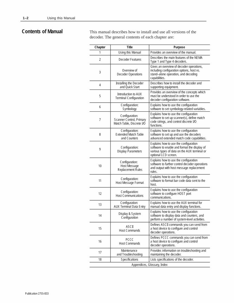
This manual describes how to install and use all versions of thedecoder. The general contents of each chapter are:
Chapter Title Purpose
1 Using this Manual Provides an overview of the manual.
2 Decoder Features Describes the main features of the NEMAType 1 and Type 4 decoders.
3 Overview ofDecoder Operations
Gives an overview of decoder operations,including configuration options, host vs.stand–alone operation, and decodingcapabilities.
4 Installing the Decoderand Quick Start
Describes how to install the decoder andsupporting equipment.
5 Introduction to AUXTerminal Configuration
Provides an overview of the concepts whichmust be understood in order to use thedecoder configuration software.
6 Configuration:Symbology
Explains how to use the configurationsoftware to set symbology-related variables.
7Configuration:
Scanner Control, PrimaryMatch Table, Discrete I/O
Explains how to use the configurationsoftware to set up scanner(s), define matchcode strings, and control discrete I/Ofunctions.
8Configuration:
Extended Match Tableand Counters
Explains how to use the configurationsoftware to set up and use the decodersadvanced extended match code capabilities.
9 Configuration:Display Parameters
Explains how to use the configurationsoftware to enable and format the display ofvarious types of data on the AUX terminal oroptional LCD screen.
10Configuration: Host Message
Replacement Rules
Explains how to use the configurationsoftware to further control decoder operationsand output with host message replacementrules.
11 Configuration:Host Message Format
Explains how to use the configurationsoftware to format bar code data sent to thehost.
12 Configuration:Host Communications
Explains how to use the configurationsoftware to configure HOST portcommunications.
13 Configuration: AUX Terminal Data Entry
Explains how to use the AUX terminal formanual data entry and display functions.
14 Display & SystemConfiguration
Explains how to use the configurationsoftware to display data and counters, andperform a number of system-level activities.
15 ASCIIHost Commands
Defines ASCII commands you can send froma host device to configure and controldecoder operations.
16 PCCCHost Commands
Defines PCCC commands you can send froma host device to configure and controldecoder operations.
17 Maintenance and Troubleshooting
Provides information on troubleshooting andmaintaining the decoder.
18 Specifications Lists specifications of the decoder.
Appendices, Glossary, Index
Contents of Manual

1–3Using this Manual
Publication 2755-833
No special knowledge is required to read this manual or use thedecoder. However, if using the decoder to communicate with aprogrammable controller or host device, you should be familiar withcommunication devices, standards (RS-232, RS-422, RS-485) andterminology.
This manual defines commands a host device can send to the decoderand responses to those commands. However, the manual does notinclude programs which are required to generate the commands.
If this product is installed within the European Union or EEAregions and has the CE mark, the following regulations apply.
EMC Directive
This apparatus is tested to meet Council Directive 89/336Electromagnetic Compatibility (EMC) using a technical constructionfile and the following standards, in whole or in part:
• EN 50081-2 EMC – Generic Emission Standard, Part 2 –Industrial Environment
• EN 50082-2 EMC – Generic Immunity Standard, Part 2 –Industrial Environment
The product described in this manual is intended for use in anindustrial environment.
This manual contains many terms that are used within the bar codeindustry and terms that are unique to the decoder. Refer to theglossary at any time for definitions of these terms.
The following conventions are used in this manual:
• All configuration menus and screens are approximate renderingsof what you see on the terminal screen, although Allen-Bradleyreserves the right to make minor modifications to any menu orscreen to help improve performance.
• A symbol or word in brackets represents a single key you presson the computer keyboard. For example: [Esc], [Enter],[Backspace].
On some computers, the [Enter] key is labelled [↵ ] or [Return].
• The built-in configuration screens of the decoder have manyconfiguration parameters which are referred to throughout themanual. Parameter names are italicized within text.
• Information which you can select or enter into the menus orscreens appear in the text in bold type.
What You Need to Know
European Union DirectiveCompliance
Terminology
Conventions Used

1–4 Using this Manual
Publication 2755-833
• We have prepared this manual assuming you are using a completeimplementation of the product: a dual-head scanner withPharma-Code capabilities and LCD screen.
You should apply its contents as appropriate to your ownimplementation. For instance, references to Scanner B will notapply to single–head decoders.
• We refer to all possible configurations of series 2755 decoders(NEMA Type 1 or Type 4, single or dual-head, with or withoutthe optional LCD screen, or with or without Pharma–Codecapabilities) as the decoder.
Other publications to which you may want to refer include:
• User’s Manual for the 2755-L7 and -L9 Scan HeadsCatalog No. 2755-ND002
• User’s Manual for the 2755-L4F and -L4REnhanced Medium Speed Scan HeadsPublication 2755-829
• User’s manual for the 2755-LD4 and -LD8 High PerformanceVisible Laser Diode ScannersPublication 2755-832
• Product Data for the 2755-NC16 Gun AdapterCatalog No. 2755-2.37
• User’s Manual for the 2760-RB Flexible Interface ModuleCatalog No. 2760-ND001
• User’s Manual for the 2760-SFC1 Protocol CartridgeCatalog No. 2760-ND003
• User’s Manual for the 2760-SFC2 Protocol CartridgeCatalog No. 2760-ND002
• User’s Manual for the 1771-DA ASCII I/O ModulePublication No. 1771-6.5.13
• User’s Manual for the 1771-DB BASIC ModulePublication No. 1771-6.5.34
Related Publications

������ �
Publication 2755-833
������ ������
This chapter describes features of the Dual-Head Bar CodeDecoders, including available options and accessories. It covers:
• NEMA type enclosures
• scanner ports
• power supply
• LED indicators
• serial communication ports (HOST port and AUX port)
• LCD display
• discrete input/output modules
The 2755-DS1_ and -DD1_ decoders have NEMA Type 1enclosures. The 2755-DS4_ and 2755-DD4_ decoders have NEMAType 4 enclosures. All connections and ports on the NEMA Type 4enclosure comply with NEMA 4 standards.
Although the installation varies for the NEMA Type 1 and Type 4decoders, they have the same features and operate identically.
Single-head decoders have one port for connecting a scanner. Thatport is designated Scanner Port A. Dual-head decoders have twoports for connecting scanners. They are designated Scanner Port Aand B.
Both ports support scanners from the 2755-L4/L5, -L7/L9, –LD4 and–LD8① families with the appropriate cables. The scanners do notrequire a separate power supply. They receive power from thedecoder through the cable. The NEMA Type 1 decoder also supportsthe 2755-G3 and –G6 Hand-Held Scanners and 2755–LD1 and–LD2 Scanners.②
① Catalog Numbers are incomplete. The 2755-L4/L5, –L7/L9, –LD4 and LD8 scanners are availablein different configurations.
② The 2755-G3 and –G6 Hand-Held Scanners and 2755–LD1 and –LD2 Scanners require the2755-NC16 Gun Adapter.
Chapter Objectives
NEMA Type Enclosures
Scanner Ports

2–2 Decoder Features
Publication 2755-833
Dual-head scanners can operate in two modes:
• Independent Mode
Both scanners operate independently of one another, each using aseparate trigger source (Scanner A and Scanner B).
• Coordinated Mode
Both scanners operate in a coordinated mode, each using thesame trigger source (Scanner A).
An internal power supply provides power to both the laser scanner(s)and the decoder. The source voltage may range from 100 to 240 voltsAC nominal (50 to 60 Hz). The power supply automatically adjuststo the input voltage.
Figure 2.1NEMA Type 1 Decoder (Catalog No. 2755-DD1A)
POWER
ALLEN-BRADLEY BAR CODE DECODER
POWERCPU ACTIVECOMMUNICATION
LASER ON ATRIGGER ACTIVE AVALID READ A
LASER ON BTRIGGER ACTIVE BVALID READ B
DISCRETE I/O
1 2 3 4 5 6 7 8
SCANNER A PortSCANNER B Port(DD Versions Only)
AUX PortRS-232
HOST PortRS-232/422/485
Optional LCD Display
LED Indicators
IEC 320 Power Connectorand ON/OFF SwitchHoles for Conduit or Optional Output Module Connectors
(shown installed on left and plugged on right).
Power Supply

2–3Decoder Features
Publication 2755-833
Seventeen front panel indicators provide a visual indication of theoperating status of the dual-head decoders. There are fourteen frontpanel indicators on single-head decoders. Table 2.A defines the colorand function of each LED.
Table 2.ALED Indicators (NEMA Type 1 and Type 4 Decoders)
LED Label Color Lights when
Power Green The decoder is receiving power.
CPU Active Green The CPU is active and running. The LED turns off if a fault condition is detected.
Communications Yellow Data is transmitting to or from the AUX port or HOST port.
Laser On A Red Scanner A is activated to turn on its laser light source. ①
Trigger Active A Yellow The decoder is in triggered mode and scanning has been triggered for Scanner A or Scanner B.
Valid Read A Green A valid read occurs from Scanner A.
Laser On B Red Scanner B is activated to turn on its laser light source. ① . (Dual-head versions only)
Trigger Active B Yellow The decoder is in triggered mode and scanning has been triggered for Scanner A or B. (Dual-head versions only)
Valid Read B Green A valid read occurs from Scanner B. (Dual-head versions only)
Discrete I/O (1-8) Red Input/output module in position 1,2, 3, 4, 5, 6, 7, or 8 is active.① The LED will light even if the scanner is disconnected or the Laser On switch for the scanner is in
the OFF position.
Figure 2.2NEMA Type 4 Decoder (Catalog No. 2755-DD4A)
ALLEN-BRADLEY BAR CODE DECODER
POWERCPU ACTIVECOMMUNICATION
LASER ON ATRIGGER ACTIVE AVALID READ A
LASER ON BTRIGGER ACTIVE BVALID READ B
DISCRETE I/O
1 2 3 4 5 6 7 8
Optional LCD Display
ON/OFFToggle Switch
NEMA Type 4 Power Connector
SCANNER APort
SCANNER B Port(DD Versions Only)
AUX PortRS-232
HOST PortRS-232/422/485
LED Indicators
Holes for Conduit or Optional Output Module Connectors(shown installed on left and plugged on right).
LED Indicators

2–4 Decoder Features
Publication 2755-833
The decoders support an optional 2 line x 20 character per linealphanumeric LCD Display for viewing:
• bar code data
• output counter values
• decoder performance values
The format of the display data is under user control via theconfiguration screens or host commands.
The LCD Display can be factory installed or ordered as a separatecomponent for customer installation.
The AUX port communicates with a standard ASCII terminal usingthe RS-232 interface. We refer to this terminal as the AUX terminal.The AUX port can switch between two modes of operations.
Decoder Configuration
The AUX terminal is used to configure and monitor decoderoperations.
Manual Data Entry
The AUX terminal is used to:
• enter data at the keyboard when the unattended scanners cannotread a label
This feature is useful when labels are damaged or missing.
• display messages from the host
• display bar code data, output counters, and decoder status
The decoder features an AUX Terminal jumper on the main logicboard to switch between configuration and manual data entryoperations. Another way to switch between these two modes is toconnect specific pins in the AUX port connector. The port and logicboard jumpers are initially set for decoder configuration operations.
Important: The two operational modes described above aremutually exclusive. You can use the port for eitherdecoder configuration or for manual data entryfunctions, but not both. Refer to Chapter 13 foradditional information.
LCD Display
AUX Port

2–5Decoder Features
Publication 2755-833
The HOST port supports RS-232, RS-422, and RS-485 (usingAllen-Bradley DH485 protocol) interfaces. The HOST port allowsthe exchange of data between the decoder and a host computer orAllen-Bradley PLC controller.
The NEMA Type 1 decoder uses an IEC 320 power entry connector.
The NEMA Type 4 decoder uses a standard 3-pin connector with aseparate ON/OFF toggle switch (that is sealed to comply withNEMA Type 4 standards).
Power cord options are available for each decoder and are listed inthe Decoder Options section.
The decoders are designed to retain configuration during short termpower interruptions. Controlled discharge of an on-board capacitorsupports configuration retention for 6 hours at an ambienttemperature of 50�C (122�F), or 50 hours at 30�C (86�F). Thecapacitor accumulates a charge when power is restored.
An optional battery (catalog number 1747-BA) may be used to retainthe configuration without outside power for up to five years. Whenthe optional battery is used, power interruptions (whether intentionalor resulting from power supply “glitches”) will have no affect onoperating memory.
If the battery is not used, long term power loss (see above) will resultin the loss of the Extended Match Code Table configuration, thePrimary and Extended Match Code Counters, and the text examplescontained in the Host Replacement Rules. Note that the ReplacementRules themselves will not be lost, but the test examples you haveentered at the bottom of each rule page will be lost.
Storage memory configuration is transferred into operating memoryon restart if power is lost for a period longer than the on-boardcapacitor (and, if installed, optional battery) can support. Refer toChapter 3 for an explanation of decoder memory architecture.
The decoders support an optional I/O Module Board with eightpositions for output modules. These I/O modules are used to controlexternal AC or DC devices. Conditions that activate the outputs areunder user control via the configuration screens or host commands.
Host Port
Power Connector andOn/Off Switch
Memory Backup
Discrete I/O Modules

2–6 Decoder Features
Publication 2755-833
All positions accept an output module. Position eight also accepts aninput module. You can configure the input module (in position 8) toautomatically load scanned bar code data into the match code table.This function is referred to as Autoload Input. Match code functionsare described in detail in Chapters 7 and 8.
Each decoder has two conduit holes or optional connectors forwiring the I/O modules.
The I/O Module Board is available in several variations for factoryor customer installation. You can order the decoder with the I/OModule Board only for customer installation of specific modules, orwith 2 DC outputs and 1 DC input for ”out of the box” applications.
The options available for the NEMA Type 1 and Type 4 decodersare:
• I/O board without modules
• I/O board with 2 DC output modules and 1 DC input module
• I/O board with 1 NEMA Type 4 connector and cable for installingup to 4 modules in positions 1-8.
• I/O board with 2 NEMA Type 4 connectors and cables forinstalling up to 8 modules in positions 1-8.
• I/O board with 2 DC output modules, 1 DC input module and 2NEMA Type 4 connectors/cables for installing up to 8 modules inpositions 1-8.
Each option is listed under Decoder Options in this chapter.

2–7Decoder Features
Publication 2755-833
Options available when ordering the NEMA Type 1 decoder arelisted inside the decoder’s cover as shown below. Note that on actualproduction labels:
• the base catalog number will appear in the first field following thewords “Cat No.”
• the series letter will appear in the field following “Ser.”
• the revision letter will appear in the field following “Rev.”.
CAT. NO. SER. REV.
POWER CORD
0 = NONE1=240VAC U.S.2=240VAC EUROPEAN
USER MANUAL
U=NONEBLANK=ENGLISH
I/O
B1=I/O BOARDB2=I/O BOARD,
(1) D.C. IN. (2) D.C. OUTB5=I/O BOARD,
1 CONN. & CABLE
B6=I/O BOARD,2 CONN. & CABLES
B7=I/O BOARD, (2) CONN. & CABLES(1) D.C. IN. , (2) D.C. OUT
BLANK=NONE
DISPLAY MODULE
R1=DISPLAYBLANK=NONE
BLANK=120VAC U.S.
Power Cords
Power cords available when ordering the NEMA Type 1 decoder are:
Option Power Cord Description
Blank 120 VAC, IEC 320, terminated three prong, U.S. style power cord, 6 ft. (1.83m)①
-0 No power cord (User must supply appropriate power cord)
-1 240 VAC, IEC 320, three wire (U.S. Color Code) unterminated power cord, 6 ft.(1.83 m)
-2 240 VAC, IEC 320, three wire (European Harmonized) unterminated powercord, 2.5 m (8 ft. 2 in)②
① Supplied with decoder if alternate power cord is not specified in catalog number.
② The decoder is not UL listed/CSA approved when used with EuropeanHarmonized power cords.
To order a replacement power cord for the NEMA Type 1 decoder,use the following replacement part numbers.
ReplacementPart No. Power Cord Description
77121-801-01 120 VAC, IEC 320, terminated, 6 ft. three prong, U.S. style power cord, 6 ft.(1.83 m)
77121-801-02 240 VAC, IEC 320, three wire (U.S. Color Code) unterminated power cord, 6 ft.(1.83 m)
77121-801-03 240 VAC, IEC 320, three wire (European Harmonized) unterminated powercord, 2.5 m (8 ft. 2 in)①
① The decoder is not UL listed/CSA approved when used with EuropeanHarmonized power cords.
Decoder Options(NEMA Type 1 Decoders)

2–8 Decoder Features
Publication 2755-833
Options available when ordering the NEMA Type 4 decoder arelisted inside the decoder’s cover. Note that on actual productionlabels:
• the base catalog number will appear in the first field following thewords “Cat No.”
• the series letter will appear in the field following “Ser.”
• the revision letter will appear in the field following “Rev.”.
CAT. NO. SER. REV.
POWER CORD
0 = NONE3 = NEMA 4 EuropeanBLANK = NEMA 4 U.S.
USER MANUAL
U = NONEBLANK = ENGLISH
I/O
B1 = I/O BOARDB2 = I/O BOARD,
(1) D.C. IN. , (2) D.C. OUTB5 = I/O BOARD,
1 CONN. & CABLE
B6 = I/O BOARD,2 CONN. & CABLES
B7 = I/O BOARD, (2) CONN. & CABLES(1) D.C. IN. (2) D.C. OUT
BLANK=NONE
DISPLAY MODULE
R1 = DISPLAYBLANK = NONE
Power Cords
Power cords available when ordering the NEMA Type 4 decoderinclude:
OptionPower Cord Description
Blank 120/240 VAC, three wire (US Color Code) unterminated power cord, 6 ft. (1.83 m)①
-0 No power cord (User must supply appropriate power cord)
-3 240 VAC, three wire (European Harmonized) unterminated power cord, 6 ft. (1.83 m)②
① Supplied with decoder if alternate power cord is not specified in catalog number.
② The decoder is not UL listed/CSA approved when used with European Harmonized power cords.
To order a replacement power cord for the NEMA Type 4 decoder,use the following replacement part numbers.
Replacement Number Power Cord Description
77121-801-04 120/240 VAC, three wire (US Color Code) unterminated power cord
71721-801-05 240 VAC, three wire (European Harmonized) unterminated power cord①
① The decoder is not UL listed/CSA approved when used with European Harmonized power cords.
Decoder Options(NEMA Type 4 Decoders)
2–9Decoder Features
Publication 2755-833
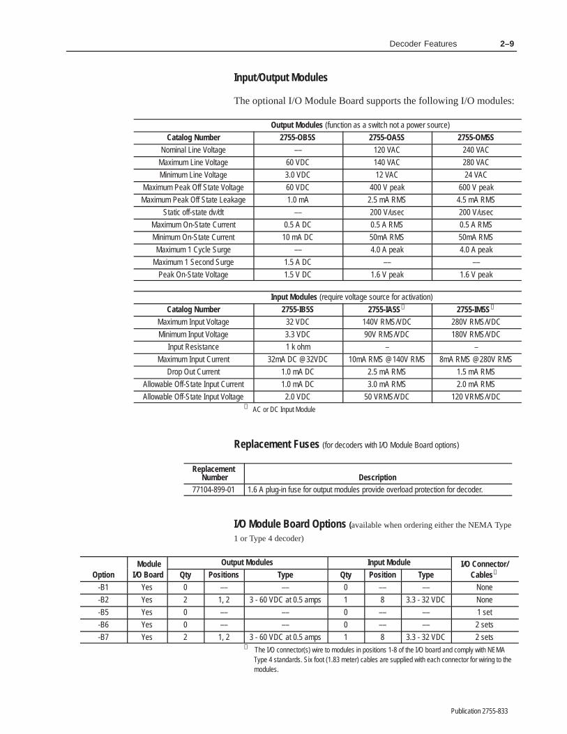
Input/Output Modules
The optional I/O Module Board supports the following I/O modules:
Output Modules (function as a switch not a power source)
Catalog Number 2755-OB5S 2755-OA5S 2755-OM5S
Nominal Line Voltage –– 120 VAC 240 VAC
Maximum Line Voltage 60 VDC 140 VAC 280 VAC
Minimum Line Voltage 3.0 VDC 12 VAC 24 VAC
Maximum Peak Off State Voltage 60 VDC 400 V peak 600 V peak
Maximum Peak Off State Leakage 1.0 mA 2.5 mA RMS 4.5 mA RMS
Static off-state dv/dt –– 200 V/usec 200 V/usec
Maximum On-State Current 0.5 A DC 0.5 A RMS 0.5 A RMS
Minimum On-State Current 10 mA DC 50mA RMS 50mA RMS
Maximum 1 Cycle Surge –– 4.0 A peak 4.0 A peak
Maximum 1 Second Surge 1.5 A DC –– ––
Peak On-State Voltage 1.5 V DC 1.6 V peak 1.6 V peak
Input Modules (require voltage source for activation)
Catalog Number 2755-IB5S 2755-IA5S① 2755-IM5S①
Maximum Input Voltage 32 VDC 140V RMS/VDC 280V RMS/VDC
Minimum Input Voltage 3.3 VDC 90V RMS/VDC 180V RMS/VDC
Input Resistance 1 k ohm – –
Maximum Input Current 32mA DC @32VDC 10mA RMS @140V RMS 8mA RMS @280V RMS
Drop Out Current 1.0 mA DC 2.5 mA RMS 1.5 mA RMS
Allowable Off-State Input Current 1.0 mA DC 3.0 mA RMS 2.0 mA RMS
Allowable Off-State Input Voltage 2.0 VDC 50 VRMS/VDC 120 VRMS/VDC① AC or DC Input Module
Replacement Fuses (for decoders with I/O Module Board options)
Replacement Number Description
77104-899-01 1.6 A plug-in fuse for output modules provide overload protection for decoder.
I/O Module Board Options (available when ordering either the NEMA Type
1 or Type 4 decoder)
Module Output Modules Input Module I/O Connector/Option I/O Board Qty Positions Type Qty Position Type Cables①
-B1 Yes 0 –– –– 0 –– –– None
-B2 Yes 2 1, 2 3 - 60 VDC at 0.5 amps 1 8 3.3 - 32 VDC None
-B5 Yes 0 –– –– 0 –– –– 1 set
-B6 Yes 0 –– –– 0 –– –– 2 sets
-B7 Yes 2 1, 2 3 - 60 VDC at 0.5 amps 1 8 3.3 - 32 VDC 2 sets① The I/O connector(s) wire to modules in positions 1-8 of the I/O board and comply with NEMA
Type 4 standards. Six foot (1.83 meter) cables are supplied with each connector for wiring to themodules.

2–10 Decoder Features
Publication 2755-833
There are three I/O Module Board options available for customerinstallation in any 2755 decoder.
Catalog number 2755-NB0 includes a NEMA Type 4 connector anda 6 foot (1.83 meter) unterminated cable. Each connector and cablecombination can connect to as many as four modules.
Catalog number 2755-NB1 includes an I/O Board (withoutmodules).
Catalog number 2755-NB2 is a kit including two DC output modules(3 to 60 VDC at 0.5 amps), one input module (3.3 to 32 VDC), andthe I/O board.
Catalog Module Output Modules Input Module I/O Connector/Number I/O Board Qty Positions Type Qty Position Type Cables①
2755-NB0 No 0 –– –– 0 –– –– 1 set
2755-NB1 Yes 0 –– –– 0 –– –– None
2755-NB2 Yes 2 1, 2 3 - 60 VDC at 0.5 amps 1 8 3.3 - 32 VDC None① The I/O connector(s) wire to modules in positions 1-8 of the I/O board and comply with NEMA
Type 4 standards. Six foot (1.83 meter) cables are supplied with each connector for wiring to themodules.
LCD Display
The optional 2 line by 20 character LCD backlit display is availablewhen ordering the NEMA Type 1 or Type 4 decoder by specifyingdisplay option R1 in the catalog number.
The display is also available for customer installation as Catalog No.2755-NR1.

2–11Decoder Features
Publication 2755-833
The following table provides a quick reference guide to theAllen-Bradley scanners that are available for use with the decoders.
Catalog No. Description
2755-LD8① High Performance Visible Laser Diode Bar Code Scanner. 500 scan per second fixed mount scanners with readdistances up to 50 inches (1.27 meters) depending on the symbol size and quality.
2755-LD4① High Performance Visible Laser Diode Bar Code Scanner. 200 scan per second fixed mount scanners with readdistances up to 84 inches (2.13 meters) depending on the symbol size, quality, and scanner range selected.
2755-L9① Industrial NEMA Type 4 High Speed Bar Code Scanner. 800 scan per second raster and side scanning device withread distances up to 30 inches (76 cm) depending upon symbol size and quality.
2755-L7① Industrial NEMA Type 4 Bar Code Scanner. 350 scan per second raster and side scanning device with read distancesup to 50 inches (1.27 meters) depending upon symbol size and quality.
2755-L4F① -L4R①
Enhanced NEMA Type 12 Bar Code Scanner. 200 scan per second front or side scanning device with read distancesup to 50 inches (1.27 meters) depending upon symbol size and quality.
2755-L5R① Enhanced NEMA Type 12 Raster Scanner. 200 scan per second raster scanner with read distances up to 45 inches(1.14 meters) depending on symbol size and quality.
2755-G3①➁ Hand-Held Laser Scanner. Non-contact scanners that can read bar code symbols at distances of 1 inch to 30 inches(2.5 to 76.2 cm).
2755-G6①➁ Hand-Held Laser Scanner. Non-contact scanners that can read bar code symbols at distances of 8 to 66 inches (20.3to 167.6 cm).
2755-LD1①➁ Standard Range Fixed Mount Laser Scanner. 36 scan per second “stop and scan” scanners that can read bar codesymbols at distances from 1 inch to 30 inches (2.5 to 76.2 cm) depending upon symbol size and quality.
2755-LD2①➁ Long Range Fixed Mount Laser Scanner. 36 scan per second “stop and scan” scanners that can read bar code sym-bols at distances from 8 to 66 inches (20.3 to 167.7 cm) depending upon symbol size and quality.
① Catalog Number is not complete. The scanners are available in a variety of configurations. Checkcompatibility of new scanners with your Allen-Bradley representative.
➁ These scanners require the 2755-NC16 Gun Adapter to function with these decoders.
This section lists the accessories that are available for the NEMAType 1 and Type 4 decoders.
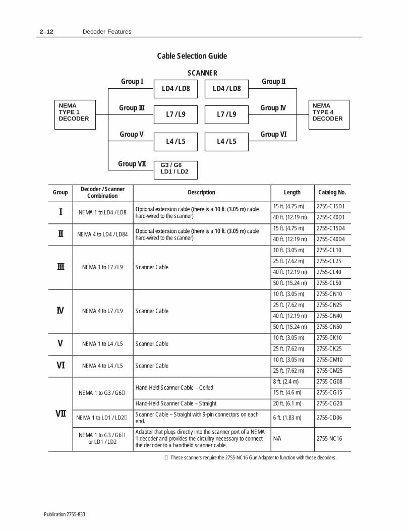
Configuration and Cable Group Selector
Use the chart below and the Cable Selection Guide table that followsit to determine which cables are appropriate to your own application.
To use the chart, simply identify the scanner you are using in thecenter column, then look to the left if you are using a NEMA Type 1decoder, or to the right if you are using a NEMA Type 4 decoder. Acable group identification number appears over the line connectingyour scanner with your decoder type. For example, if you are usingan -LD4 scanner with a NEMA Type 4 decoder, you would select aGroup II cable.
Scanners
Decoder Accessories
2–12 Decoder Features
Publication 2755-833
Cable Selection Guide
SCANNER
L4 / L5
LD4 / LD8
L7 / L9
G3 / G6LD1 / LD2
NEMATYPE 1DECODER
NEMATYPE 4DECODER
Group I
Group III
Group V
Group VII
Group II
Group IV
Group VIL4 / L5
LD4 / LD8
L7 / L9
Group Decoder / ScannerCombination Description Length Catalog No.
I A to Optional extension cable (there is a 10 ft. (3.05 m) cablea d i d to t cann
15 ft. (4.75 m) 2755-C15D1I NEMA 1 to LD4 / LD8 Optional extension cable (there is a 10 ft. (3.05 m) cable
hard-wired to the scanner) 40 ft. (12.19 m) 2755-C40D1
II A to Optional extension cable (there is a 10 ft. (3.05 m) cablea d i d to t cann
15 ft. (4.75 m) 2755-C15D4II NEMA 4 to LD4 / LD84 Optional extension cable (there is a 10 ft. (3.05 m) cable
hard-wired to the scanner) 40 ft. (12.19 m) 2755-C40D4
10 ft. (3.05 m) 2755-CL10
III A to cann abl25 ft. (7.62 m) 2755-CL25
III NEMA 1 to L7 / L9 Scanner Cable40 ft. (12.19 m) 2755-CL40
50 ft. (15.24 m) 2755-CL50
10 ft. (3.05 m) 2755-CN10
I A to cann abl25 ft. (7.62 m) 2755-CN25
IV NEMA 4 to L7 / L9 Scanner Cable40 ft. (12.19 m) 2755-CN40
50 ft. (15.24 m) 2755-CN50
A to cann abl10 ft. (3.05 m) 2755-CK10
V NEMA 1 to L4 / L5 Scanner Cable25 ft. (7.62 m) 2755-CK25
I A to cann abl10 ft. (3.05 m) 2755-CM10
VI NEMA 4 to L4 / L5 Scanner Cable25 ft. (7.62 m) 2755-CM25
and ld cann abl oil d8 ft. (2.4 m) 2755-CG08
NEMA 1 to G3 / G6➀Hand-Held Scanner Cable – Coiled
15 ft. (4.6 m) 2755-CG15
IIHand-Held Scanner Cable – Straight 20 ft. (6.1 m) 2755-CG20
VII NEMA 1 to LD1 / LD2➀Scanner Cable – Straight with 9-pin connectors on eachend.
6 ft. (1.83 m) 2755-CD06
NEMA 1 to G3 / G6➀or LD1 / LD2
Adapter that plugs directly into the scanner port of a NEMA1 decoder and provides the circuitry necessary to connectthe decoder to a handheld scanner cable.
N/A 2755-NC16
➀ These scanners require the 2755-NC16 Gun Adapter to function with these decoders.

2–13Decoder Features
Publication 2755-833
Package Detectors for Scanners
Scanner Description Catalog No.L7 / L9 Optional, for Catalog No. 2755-L7, -L9 Scan Head. DC retroflective detector with an operating range up to 18 feet
(5.49 meters). Mounts from front or rear, plus head rotation allows additional flexibility in selecting sending direc-tion.
2755-NP3
Optional, for Catalog No. 2755-L7, -L9 Scan Head. Polarized beam retroflective detector has a maximum operatingdistance of 10 feet (3.03 meters) or 8 feet (2.43 meters) with a 2 to 1 operating margin. Includes mounting bracketsfor single-hole or flat surface mounting.
2755-NP5
L4 / L5 Optional, for Catalog No. 2755-L4, -L5 Scan Head. DC retroflective detector with an operating range up to 18 feet(5.49 meters). Mounts from front or rear, plus head rotation allows additional flexibility in selecting sending direc-tion.
2755-NP1
Optional, for Catalog No. 2755-L4, -L5 Scan Head. Polarized beam retroflective detector has a maximum operatingdistance of 10 feet (3.03 meters) or 8 feet (2.43 meters) with a 2 to 1 operating margin. Includes mounting bracketsfor single-hole or flat surface mounting.
2755-NP4
We recommend using Allen-Bradley Photoswitch� packagedetectors (PhotoSeries 6000 or 9000) with 2755-LD4 and -LD8scanners. You must order a current sinking type sensor with the QD(Quick Disconnect) suffix that is capable of operating with a +12VDC source (pin 1) and drawing not more than 100 mA and a sinkcapability of 5 mA at +12V DC.
For example: Catalog Number 42SRU-6203-QD orCatalog Number 42GRU-9200-QD
Communication Cable and Connector Kit
A cable and connector kit is available for the AUX and HOST portsof the NEMA Type 4 decoder. We recommend using CatalogNumber 2755-NC17 to make your own cable for RS-422 or RS-485.Pinouts can be found in Appendices D and E. Use Catalog Number2755-CT1 only for RS-232. Order as separate components using thefollowing catalog numbers.
Catalog Number
NEMAType Product Description
2755–NC17 4 Connector Kit 19-pin NEMA 4 Host or AUX port connectors. Used to make custom NEMA 4 communicationcables.
2755–CT1 4 Interface Cable 10 foot cable with NEMA Type 4 connector on one end for connecting to HOST or AUX port ofNEMA Type 4 Decoder and 25-pin DB connector on other end for connecting to a host device orprogramming terminal (for RS-232 only).
2755–CY1 4 Host Port Interface Cable
Multidrop interface cable for DH485 applications using NEMA Type 4 decoders.
������ �
Publication 2755-833
��� ��� �� ������ ��� ����
This chapter defines the function of the decoder and gives anoverview of decoder operations, including:
• function of decoder
• supported bar code symbologies
• configuration options
• stand-alone vs. host operations
• types of memory
• decoder operating modes
The decoder acquires and decodes video information from one ortwo scanners. The decoder can then:
• send the decoded data to a host device (host computer,programmable logic controller), ASCII terminal, or LCD display
• compare the decoded data to previously stored data and use theresults to operate up to eight discrete outputs (match codeoperation)
The decoder also maintains counters for package count, no-reads,and discrete output operations.
The decoder supports the following bar code symbologies:
• Code 39 (standard character set)
• Pharma–Code (available on DSzP and DDzP catalog numbersonly)
• UPC-A and UPC-E including optional 2 or 5 digit supplements
• EAN-8 and EAN-13 including optional 2 or 5 digit supplements
• Code 128
• Codabar
• Interleaved 2-of-5
You can configure or monitor decoder operations using the built-inconfiguration screens or by sending commands from a host device,such as a PLC controller or computer. Both configuration optionsallow you to:
• select a bar code symbology for decoding operations
• define operating parameters for the scanner(s)
• set host message format for decoded bar code data
Chapter Objectives
Function of Decoder
Bar Code Symbologies
Configuration Options

3–2 Overview of Decoder Operations
Publication 2755-833
• set host communication parameters
• define up to 8 primary and 128 extended match codes
• specify up to eight discrete outputs and the conditions that willactivate each output
• set display format for data on LCD display and/or AUX portterminal
• define operating parameters for AUX port ASCII terminal whenused for manual data entry
Configuration Screens
The decoder has built-in menus and screens for configuration andmonitoring operations. You access these menus by connecting one ofseveral standard ASCII terminals (or a computer emulating one ofthose terminals) to the AUX port of the decoder. The process ofconfiguring the decoder at the AUX port is called AUX terminalconfiguration.
The configuration menus support five different languages: English,French, German, Italian, and Spanish.
Host Commands
The decoder also supports a set of host commands for configuringthe decoder and monitoring operations. Host commands are sent tothe decoder from a PLC controller or computer and perform thesame functions as the configuration software.
The HOST port accepts commands using the RS-232 and RS-422interfaces and a variety of communication protocols, as well as theRS-485 interface using Allen-Bradley DH485 protocol. Appendix Flists the protocol options for each interface.
The decoder can operate as a stand-alone device or connected to ahost device. As a stand-alone device, the decoder uses outputmodules to control external devices. The decoder sends discreteoutput signals to external control equipment based on the results ofdecoded data.
The discrete outputs can be controlled remotely by host commandsor manually via the configuration screens.
Chapter 7 provides information on how to control the discrete I/O.Appendixes G and H show various examples of input and outputmodule connections.
Stand-alone Operation

3–3Overview of Decoder Operations
Publication 2755-833
The decoder can also communicate directly with a host computer orPLC in a control or data collection application. The decodercommunicates with and transmits bar code data to a host computer orPLC controller via the HOST port of the decoder.
Programmable Logic Controllers (PLC)
The decoder connects to an Allen-Bradley PLC Controller in thefollowing ways (see Figure 3.1):
1. Flexible Interface Module (Catalog No. 2760-RB) whichsupports a:
– point-to-Point link using the RS-232, RS-422, or DH485interface to the HOST port
– multi-drop link using the DH485 interface of the HOST portand the Flexible Interface Module.Each port of the Module operates as a separate network,supporting up to 31 decodersUse the Catalog No. 2760-SFC2 protocol cartridge with theFlexible Interface Module and configure the decoder forDH485 mode.
2. Catalog No. 1771-DB BASIC Module or 1771-DA ASCII I/OModule connects decoder directly to a PLC.
3. Programmable logic controllers from the Allen-Bradley PLC-5�
family of products that support an RS-232 ASCII port.
Host Operation

3–4 Overview of Decoder Operations
Publication 2755-833
Figure 3.1 PLC Controller Configurations
Catalog No1771-DB BASIC I/OModule➀
PLCProcessor
Catalog No.1771-DA
ASCII I/O Module1771
DA
PLC with ASCII or BASIC Module to Decoder using RS-232
1771
DB
2755–DS/DDDecoder
2755–DS/DDDecoder
Requires BASIC Driver for communications betwee1771-DB BASIC Module and Bar Code Decoder.
Multi-drop Link using Flexible Interface Module and DH485 Data Link
.....
PLCProcessor
Flexible Interface Module with2760-SFC2 Protocol Cartridge
1771-1/OI/ORack
.....
PLCProcessor
Flexible InterfaceModule with
2760-SFC1 or -SFC2 Protocol Cartridge
Point-to-Point Link using Flexible Interface Module RS-232, RS-422, or DH485 (point-to-point)
1771-1/OI/ORack
1 2 31
1 2 31
31 2 1
2755–DD1A/4ADecoder
2755–DD1A/4ADecoder
2755–DD1A/4ADecoder
2755–DD1A/4ADecoder
2755–DD1A/4ADecoder
2755–DD1A/4ADecoder
2755–DD1A/4ADecoder
2755–DD1A/4ADecoder
2755–DD1A/4ADecoder
2755–DD1A/4ADecoder
2755–DD1A/4ADecoder
2755–DD1A/4ADecoder
2755-CY1 withNEMA Type 4 device or2760-A485 connectors withNEMA Type 1 device
PLCProcessor
1771-1/OI/ORack
2755–DD1A/4ADecoder
Point-to-Point Link using PLC-5 family processorwith serial ASCII port.
➀
1746 1/OI/ORack
SLC 5/03 Controller Multidrop Using DH485 Datalink
SLC 5/03Controller
2755–DD1A/4ADecoder
31 2 31
2755–DD1A/4ADecoder
2755–DD1A/4ADecoder
1747-AIC LinkCouplerModuleModule
1747-C11 Cable

3–5Overview of Decoder Operations
Publication 2755-833
Host Computers
The decoder connects directly to other host computers using theRS-232 or RS-422 interface of the host device, or can bemulti-dropped (with DH485) through a 1784-KR module.
2755–DD1A/4ADecoder
The Series B decoder has two types of memory:
• operating memory
• storage memory.
Figure 3.2 shows the relationship of the types of memory, and thetext that follows summarizes their contents.
Figure 3.2 Memory Areas of Decoder
Operating Memory
Storage Memory FactoryDefaults
User InterfaceAUX Terminal
Host Commands
DecoderPerformance or
Operation
SAVERECALL/RESTART & STARTUP
(Following loss of memorybackup)
DEFAULT
Types of Memory

3–6 Overview of Decoder Operations
Publication 2755-833
Operating Memory
The decoder uses configuration parameters as they exist in operatingmemory to perform all functions. Initially set to factory defaults,these parameters can be changed using the AUX terminalconfiguration and ASCII or PCCC host commands. With theexception of specific host communication parameters (See Chapter12), all parameters take effect immediately when changed①
You can use the Default command to reset the operating memory tofactory defaults. The Save command will copy the contents ofoperating memory into storage memory. When you issue a Recall,the decoder copies the Saved parameters from storage memory intooperating memory.
The decoders are designed to retain configuration in operatingmemory even during short term power interruptions. Refer toChapter 2 for information about memory backup.
Storage Memory
Within the decoder there is permanently stored a copy of the factorydefault configuration parameters. You cannot modify this copy, butcan copy them into the operating memory at any time using theDefault command.
In addition, the decoder can retain in storage memory a copy of theconfiguration parameters you have set. You can use the Savecommand to copy the operating memory into storage memory. TheRecall command copies the contents of storage memory back intothe operating memory. You will find this capability useful fortroubleshooting custom configurations, for making temporarychanges on-line, and for use with Autoload and Lot.
The Autoload parameter (in either the Primary or Extended MatchCode Table) and the Lot parameter (in the Extended Match CodeTable) allow the decoder to take scanned symbol data and load it intothe match code table. The Restart command will reset theseparameters to the originally Saved parameter so that new values canbe loaded.
① The parameters that do not change until they are saved and the decoder is restarted, involve host commu
would be disruptive to change host communications parameters while data transmission was in process.communications parameters are loaded into operating memory from storage memory during restart.

3–7Overview of Decoder Operations
Publication 2755-833
Storage memory can be thought of as programmable read onlymemory (PROM). The default parameters are stored as read only(EPROM), while the user changeable portion as retentive EEPROM.for the sake of simplicity and consistency with earlier versions of theDS/DD decoders, we will maintain the conventions that the Save andRecall commands will ask for confirmation to “SAVECONFIGURATION CHANGES TO EEPROM . . . Y/N?” and“RESTORE CONFIGURATION FROM EEPROM . . . Y/N?”
Memory Contents at Startup
Until you have modified and saved your own configurationparameters, the decoder storage memory will contain only thepermanent factory default configuration. The first time you start thedecoder it will create a copy of those factory defaults in operatingmemory.
Even on decoders without the optional battery, once you have savedthem to storage memory you will retain most of your configurationparameters even with an extended loss of power. When you restartthe decoder it will read the saved configuration parameters ratherthan the factory defaults. Parameters and values not retained afterextended power loss without a battery include:
• Extended Match Code Table Configuration, which will be lostand reset to factory defaults
• Primary Match Code Table counts, which will be lost and reset tozero
• Host Replacement Rule Examples (which are the test examplesyou have entered on the bottom half of the Host MessageReplacement Rules screen). These examples will be lost and theexample section of the screen will be cleared. Note that the rulesthemselves will be retained.
The long life of the optional battery makes it unlikely that any loss ofconfiguration or data will occur during any conceivable poweroutage in battery-backed decoders.

3–8 Overview of Decoder Operations
Publication 2755-833
This section gives a brief overview of the different operating modesof the decoder. You select these operating modes and parameterswhen configuring the decoder.
Scanning Modes
The decoder supports two scanning modes:
• Coordinated ModeScanner A and Scanner B are coordinated, using the same triggersource and set of configuration parameters.
• Independent ModeScanner A and Scanner B operate independently, each using aseparate trigger source and set of configuration parameters.
Decode Modes
The decoder has three decode modes:
• Continuous Mode
In continuous mode, the decoder attempts to decode every scan.Additional scans are accumulated until the capture count issatisfied. When the symbols per package is satisfied, a valid readoccurs. In Continuous Mode there is no concept of a No-Read.Damaged or missing symbols are ignored.
This mode is useful during initial setup to determine the optimumlocation of the scanner relative to the bar code labels.
• Continuous/Unique Mode
This mode is similar to continuous mode except the decodercompares a valid read to the previous valid read. If the valid readsare identical, the new data is discarded. In continuous/uniquemode, the decoder defines a package as a valid read if it isdifferent (unique) from the previous valid read. The Symbols Read counter and the Package counterincrement with every valid read. In Continuous/Unique Modethere is no concept of a No-Read. Damaged or missingsymbolssignals are ignored.
• Triggered Mode
In triggered mode, the decoder only attempts to decode data afterreceiving a trigger. The three trigger sources are:
– Host. The trigger source is a command generated by a hostcomputer or programmable controller
– Package Detect. The trigger source is a package detectorconnected to the scanner
Decoder Operating Modes

3–9Overview of Decoder Operations
Publication 2755-833
– Internal Timer. The trigger source is an internal timer thatcycles the trigger on and off at a set time interval
Once triggered, the decoder continuously attempts to decode barcodes until one of the following conditions occurs:
– Number of symbols (bar codes) per package count is satisfied– -Trigger off command (stop scan character) received from host
device (Host Decode mode)– -Package detect signal is no longer present (Package Detect
mode)– -No-read timer expires (Internal Timer mode)
Sending Data to Host – Speed vs. Timing
In the triggered mode, you can configure the decoder to sendinformation to a host device and/or operate the discrete outputs:
• Immediately After Valid Package (for highest speed)
This is a package with valid bar code symbols that meets thesymbols (bar codes) per package count.
The Immediately After Valid Package response mode sendsdecoded data to the discrete outputs and host immediately afterthe decode operation. This response mode is useful in high speedapplications where maximum throughput is required.
or
• At End of Trigger (for predictable timing)
The At End of Trigger response mode sends decoded data to thediscrete outputs and host when the:
– -Host sends the stop scan character (Host Decode mode)– -Package detect signal expires (Package Detect mode)– -No-read timer expires (Internal Timer mode)
This response mode is useful when timing of the discrete outputsor timing of host communications is critical.
No-read messages are always sent at the end of the trigger.
������ �
Publication 2755-833
��������� �� ��� ���
This chapter presents recommendations and instructions on how toinstall and connect equipment to the NEMA Type 1 and Type 4Single and Dual-Head Bar Code Decoders. The information isorganized by task, and can serve as a useful quick start tutorial toguide you through system installation and setup. Topics coveredinclude:
• meeting electrical and grounding requirements
• installing alternate language LED indicator labels
• mounting dimensions
• connecting power cord
• setting communication parameters
• selecting language
• selecting CRT type
• selecting operations to perform
• connecting and configuring scanners
• setting symbology parameters
• customizing setup
• connecting AUX terminal
• connecting host device
• installing and wiring optional I/O modules
Before Installation:
• verify that incoming power source is 100 to 240 volts ACnominal, 50 to 60 Hz
• protect power source with an external fuse or circuit breaker,rated at no more than 15 amps
• connect decoder to its own branch circuit (when possible) toreduce electrical noise
Install equipment using guidelines in publication NFPA 70E,Electrical Safety Requirements for Employee Workplaces. Inaddition:
• do not use signal wiring and power wiring in the same conduit
• route incoming power to the decoder using a separate pathfrom the communication cables (if paths must cross, theirintersection should be perpendicular)
Chapter Objectives
Power Requirements
ElectricalRecommendations

4–2 Installing the Decoder
Publication 2755-833
When installing the decoder in a noise-polluted industrialenvironment, consider the effects of electromagnetic interference(EMI). Factors that minimize EMI include:
• proper grounding
• shielded cables
• correct routing of wires
Grounding is an important safety measure in electrical installations.With solid-state systems, grounding also minimizes the effects ofnoise caused by electromagnetic interference (EMI).
An authoritative source on grounding requirements is the NationalElectrical Code published by the National Fire ProtectionAssociation of Boston, Massachusetts. Article 250 discusses thetypes and sizes of wire conductors and safe methods of groundingelectrical equipment and components.
The NEMA Type 1 and Type 4 decoders are shipped with LEDindicator labels in six different languages: English, French, German,Italian, Japanese, and Spanish.
The decoders are shipped with the English label installed and a sheetof five alternate labels loosely packaged. If desired, replace theEnglish label with another language label.
To replace the LED indicator label, loosen the two screws on thedecoder cover and open. The LED label insert is on the inside thecover, between the LED board and cover. Remove the insert bypulling on the gray tab. Slide the desired label into position.
Grounding
Replacing LED Label

4–3Installing the Decoder
Publication 2755-833
Figure 4.1 View of the front cover from inside
Pull on tab to remove LED Label insert
LCD Display(optional)
LED Board
Figure 4.2 shows nominal mounting dimensions in inches (and cm)for the NEMA Type 1 and Type 4 decoders. The horizontal mountingorientation is shown here.
Figure 4.2 Mounting dimensions (for reference only)
10.25 in(26.0 cm)
9.5 in(24.1 cm)
8.0 in(20.3 cm)
12.0 in(30.5 cm)
ALLEN-BRADLEY
4.6 in(11.7 cm)
MountingHoles
Allow clearance of 6 inches above and below decoder for cables
10.5 in(26.7 cm)
You can mount the decoder horizontally or vertically. Whenmounting allow clearance:
• at hinged side of cover for cover to swing open
• of 6 inches (152 mm) above the decoder to connect cables to thescanner ports and communication ports
Mounting the Decoder

4–4 Installing the Decoder
Publication 2755-833
• of 6 inches (152 mm) below the decoder to wire I/O modules andto access the power entry/power switch
To mount the decoder, we recommend that you use four 1/4 inch (M6)hex-head capscrews or bolts with flat and split lockwashers and nuts.Select a bolt that equals the thickness of the mounting surface, plusthe thickness of the washers, plus at least 1/2 inch (12.7 mm) toaccommodate the mounting brackets of the decoder and the nut.
The NEMA Type 1 decoder has a standard IEC 320 power entryconnector.
Figure 4.3 shows the available power cord options for the NEMAType 1 decoder. Unless an alternate power cord is ordered, thedecoder is shipped with a 120 VAC terminated (3 prong) U.S. powercord.
Figure 4.3 Power cord options for NEMA Type 1 decoder
Power Cord Options
0 1
Brown (Line)
Blue (Neutral)
Green/Yellow
(Earth Ground)
Green (Earth G
round)W
hite (Neutral)
Black (Line)
IEC 320 Connector
ON/OFFPower Switch
①
① 120 VAC, IEC 320 terminated (three prong) U.S. style power cord(6 ft./1.83m). Default. Shipped with decoder unless otherwise specified.
② 240 VAC, IEC 320 three wire (U.S. Color Code) unterminated power cord(6ft./1.83 m).
③ 240 VAC, IEC 320 three wire (European Harmonized Code) unterminatedpower cord. (UL listing/CSA approval not applicable when this cord is used.)( 8 ft. 2 in./2.5 m)
② ③
!ATTENTION: Disconnect incoming power and makesure the power switch on the decoder is in the offposition before connecting power cord to powersource.
The NEMA Type 4 decoder has a standard 3-pin power connectorwith a separate ON/OFF toggle switch.
Installing Power Cord

4–5Installing the Decoder
Publication 2755-833
Figure 4.4 shows the available power cord options for the NEMAType 4 decoder. Unless an alternate power cord is ordered, thedecoder is shipped with a 120/240 VAC, three wire (U.S. ColorCode) unterminated power cord.
Figure 4.4 Power cord options for NEMA Type 4 Decoder
Power Cord Options
Brown (Line)
Blue (Neutral)
Green/Yellow
(Earth Ground)
Green (Earth G
round)W
hite (Neutral)
Black (Line)1
0
ON/OFFToggle Switch Power
Connector
Line Neutral
Ground
① 120/240 VAC three wire unterminated power cord (U.S. color code) 6ft./1.83 m length. Default. Shipped with decoder unless otherwise specified.
② 240 VAC, three wire unterminated power cord (European Harmonized Code)6 ft./1.83 m. Note: UL listing/CSA approval not applicable when this cord isused.
① ②
!ATTENTION: Disconnect incoming power and makesure the power switch on the decoder is in the offposition before connecting power cord to powersource.

4–6 Installing the Decoder
Publication 2755-833
You will need a computer terminal or a personal computer withterminal emulation software (such as PROCOMM ) and an RS-232cable. Lists of compatible terminals appear in Figures 4.7 and 4.8.Wiring information appears in Appendix D. See Chapters 5 through14 for more detail on using a terminal to configure the decoder andmonitor operations.
Connect AUX Terminal
Connect your terminal’s RS-232 serial port to the AUX port of the2755-DS or -DD decoder➀ To make easy connection to the NEMAType 4 decoders, a 3.03 meter (10 foot) cable is available (Cat. No.2755-CT1).
Set Communication Parameters
Set the terminal’s serial port parameters to 9600 Baud, 8 Data Bits, 1Stop Bit, No Parity (Parity = None).
Apply Power and Select Language
Turn the decoder on. The decoder will send the Select Languagescreen to the terminal. If the screen does not appear, then press theESC key on your terminal. The Communications LED on thedecoder should light momentarily, and the decoder will resend theSelect Language screen. If the LED does not light when you pressESC, verify the terminal’s communications settings and allconnections.
➀ The AUX port supports a terminal for either configuring the decoder or for manentry. For information on use of the AUX port for manual data entry, consult Cha
Quick Start for DS/DDDecoder Configurationand Scanner Setup

4–7Installing the Decoder
Publication 2755-833
Note: When using the 2755-CT1 cable to interface with a NEMAType 4 decoder, it may be necessary to use a null modem adapter onsome computers or terminals. You can identify such equipment bycomparing the pinout supplied with your computer or terminal withthe schematic supplied with your cable. You will need a null modemif pins 2 and 3 are reversed.
Choose a language from the Select Language screen by pressing theappropriate number on your keyboard. All of the screens that followwill now be displayed in the language you select.
Select CRT Type
After you have selected a language, the Select CRT Type screen willappear on your terminal. Select a terminal type from among thoselisted.

4–8 Installing the Decoder
Publication 2755-833
Note: If the next screen that appears is not properly formatted, or ifstrange characters appear, press the ESC key to return to the SelectCRT Type screen. Review your CRT Type selection. If you areusing terminal emulation, verify that your settings are correct.
Select Operations
After you have selected a CRT type, you will see the SelectOperations menu.

4–9Installing the Decoder
Publication 2755-833
Press “1” to proceed to the Symbology configuration screen. ACaution screen will appear. This screen allows you to disable thedecoder’s optional output modules during configuration. It willappear each time you select a configuration screen from the SelectOperations menu while the outputs are enabled. More informationon this subject appears in Chapter 5. For now, press any key exceptESC to continue configuration.
Note: Restarting the decoder by selecting “E” from the SelectOperations menu after configuration will reactivate the outputmodules.
At the Symbology configuration screen, we suggest resetting thedecoder to assure that you are starting from a default configuration.To do so:
1. Press ESC to activate the command line at the bottom of thescreen.
2. Use the arrow keys to move the highlight to the “DEFAULT’option.
3. Press ENTER (or RETURN on some keyboards).
4. Confirm your intention to reset the decoder to its defaultconfiguration by answering yes to the confirmation prompt (press“Y” in English).
Set Symbology Parameters
Enable the symbology (or symbologies) you would like to read byusing the arrow keys to move the highlight to the appropriateposition. Toggle through the available selections by pressing thespace bar. Press ENTER to accept each change.

4–10 Installing the Decoder
Publication 2755-833
Note: For best performance, enable only those symbologies youintend to read. You can find additional information on selectingsymbologies in Chapter 6.
Configure Scanner(s)
Once all your symbology selections have been made, press ESC toactivate the command line at the bottom of the screen. Press ENTERto select the highlighted “Next Page”.
The Scanner Control screen will appear.
While your actual operation will vary depending on your application,you will want to follow the same basic steps during initial scannersetup. Those steps include:
1. Select the scanner based on the narrow element width (thenarrowest bar or space) and desired reading distance
Refer to Bar Code Site Survey (Pub. No. 2755-939) to verify allimportant aspects of your own application. Consult the scanner’sProduct Data Sheet or User Manual for read ranges.

4–11Installing the Decoder
Publication 2755-833
2. Turn the decoder off and connect the scanner to the decoder
3. Even if your application will use a host computer, externaldisplay, discrete I/O (input or output devices), or package detect,do not attach those devices at this time.
Figure 4.5 shows the scanners you can connect to Scanner Port Aand B of the NEMA Type 1 decoder and the cables available foreach scanner. Figure 4.6 shows the scanners you can connect toScanner Port A and B of the NEMA Type 4 decoder and thecables available for each scanner. Each shows the optionalpackage detectors connected to each scanner.
Refer to the appropriate manuals for scanner mountinginstructions.

4–12 Installing the Decoder
Publication 2755-833
Figure 4.5 Connecting scanners to NEMA Type 1 decoder
Optional ExtensionCables2755-C15D12755-C40D1
Optional ExtensionCables2755-C15D12755-C40D1
2755-NP1/NP4
Package Detector
2755-NP3/NP5
Package Detector2755-NP3/NP5
Package Detector
Cables2755-CG082755-CG152755-CG20
2755-NC16Adapter
Cables2755-CG082755-CG152755-CG20
Cables2755-CK102755-CK25
HOSTRS-232 /422 /485
SCANNER A SCANNER B AUXRS-232
CABLES2755-CL102755-CL252755-CL402755-CL50
2755-G3/G6Hand-Held Laser Scanner
OR
OR
2755–L4/L5Scanner
OR
2755–L7/L9Scanner
Cables2755-CK102755-CK25
2755-NP1/NP4
Package Detector
2755-G3/G6Hand-Held Laser Scanner
2755-NC16Adapter
2755–L7/L9Scanner
2755–L4/L5Scanner
CABLES2755-CL102755-CL252755-CL402755-CL50
OR
OR
2755–LD4/LD8Scanner
2755–LD4/LD8Scanner
OR
SeePhotoswitchCatalog
SeePhotoswitchCatalog
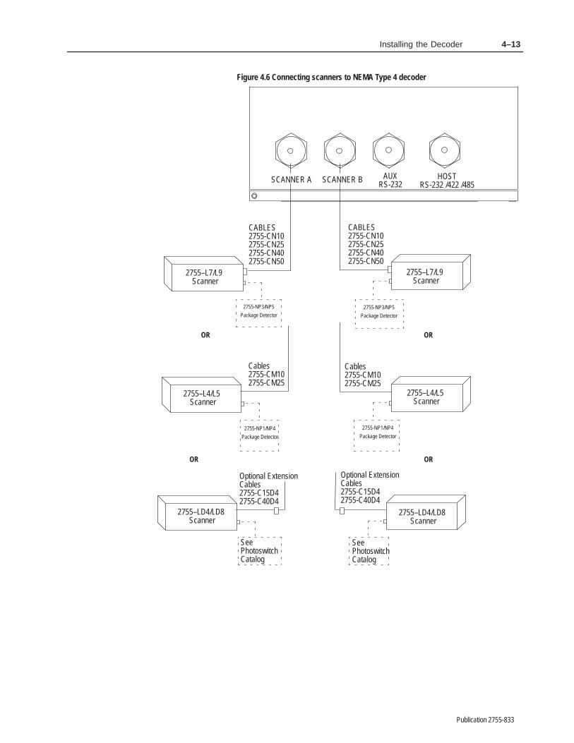
4–13Installing the Decoder
Publication 2755-833
Figure 4.6 Connecting scanners to NEMA Type 4 decoder
Cables2755-CM102755-CM25
Optional ExtensionCables2755-C15D42755-C40D4
Cables2755-CM102755-CM25
Optional ExtensionCables2755-C15D42755-C40D4
2755-NP1/NP4
Package Detector2755-NP1/NP4
Package Detector
2755-NP3/NP5
Package Detector
2755-NP3/NP5
Package Detector
HOSTRS-232 /422 /485
SCANNER A SCANNER B AUXRS-232
CABLES2755-CN102755-CN252755-CN402755-CN50
OR
2755–L4/L5 Scanner
2755–L4/L5 Scanner
OR
CABLES2755-CN102755-CN252755-CN402755-CN50
2755–L7/L9 Scanner
2755–L7/L9 Scanner
OR
2755–LD4/LD8 Scanner
2755–LD4/LD8 Scanner
OR
SeePhotoswitchCatalog
SeePhotoswitchCatalog
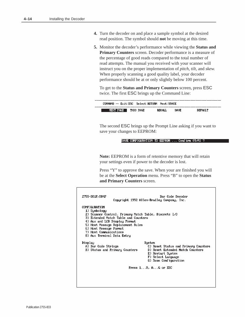
4–14 Installing the Decoder
Publication 2755-833
4. Turn the decoder on and place a sample symbol at the desiredread position. The symbol should not be moving at this time.
5. Monitor the decoder’s performance while viewing the Status andPrimary Counters screen. Decoder performance is a measure ofthe percentage of good reads compared to the total number ofread attempts. The manual you received with your scanner willinstruct you on the proper implementation of pitch, tilt , and skew.When properly scanning a good quality label, your decoderperformance should be at or only slightly below 100 percent.
To get to the Status and Primary Counters screen, press ESCtwice. The first ESC brings up the Command Line:
The second ESC brings up the Prompt Line asking if you want tosave your changes to EEPROM:
Note: EEPROM is a form of retentive memory that will retainyour settings even if power to the decoder is lost.
Press “Y” to approve the save. When your are finished you willbe at the Select Operation menu. Press “B” to open the Statusand Primary Counters screen.

4–15Installing the Decoder
Publication 2755-833
6. Adjust the position of the scanner to maximize decoderperformance.
7. Fix the scanner in this optimized position.
Customize As Required
Your system is now ready to customize for best performance in yourparticular application. The software screens used to do that havebeen structured to “walk you through” the configuration process. Werecommend stepping through the screens in the order they appear,using this manual as a reference.
If your application requires a host device or I/O modules, the nexttwo sections, “Connecting Host Device” and “Installing I/OModules” will help guide you through the hardware configurationrequired to use them.
The AUX port supports a terminal for either configuring the decoderor for manual data entry.
The AUX port on the NEMA Type 1 decoder is configured as shownbelow, and communicates over an RS-232 serial communication line.It has a 25-pin D shell (female) connector. Figure 4.7 showsterminals you can connect to the AUX port of the NEMA Type 1decoder.
Figure 4.7 Connecting terminal to AUX port of NEMA Type 1decoder
ConfigurationManual Data Entry
Supported Terminal Types
① Construct your own cable usingthe pinouts in Appendix D.
Allen-Bradley Industrial Terminals 1771-T1, -T2, -T3
Allen-Bradley 1784-T45 Laptop TerminalDEC VT100Lear Siegler ADM 3E
Computer or terminal that emulates one
HOSTRS-232 /422 /485
SCANNER A SCANNER B AUXRS-232
①
of the above
Connecting theAUX Terminal
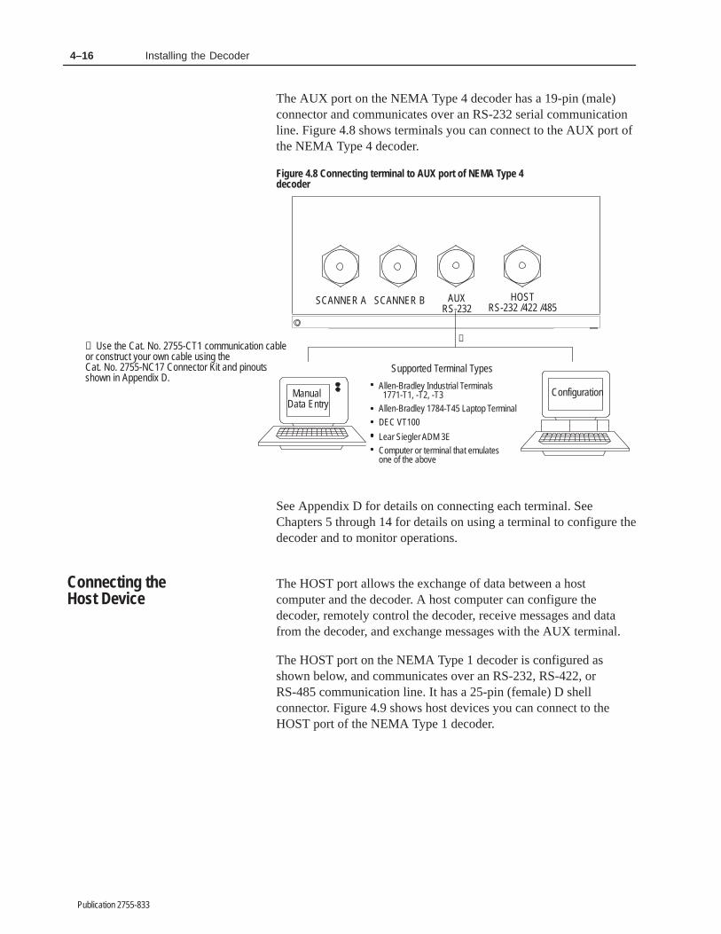
4–16 Installing the Decoder
Publication 2755-833
The AUX port on the NEMA Type 4 decoder has a 19-pin (male)connector and communicates over an RS-232 serial communicationline. Figure 4.8 shows terminals you can connect to the AUX port ofthe NEMA Type 4 decoder.
Figure 4.8 Connecting terminal to AUX port of NEMA Type 4decoder
ConfigurationManual Data Entry
Supported Terminal Types
① Use the Cat. No. 2755-CT1 communication cableor construct your own cable using theCat. No. 2755-NC17 Connector Kit and pinoutsshown in Appendix D.
Allen-Bradley Industrial Terminals 1771-T1, -T2, -T3Allen-Bradley 1784-T45 Laptop Terminal
DEC VT100
Lear Siegler ADM 3EComputer or terminal that emulates
①
HOSTRS-232 /422 /485
SCANNER A SCANNER B AUXRS-232
one of the above
See Appendix D for details on connecting each terminal. SeeChapters 5 through 14 for details on using a terminal to configure thedecoder and to monitor operations.
The HOST port allows the exchange of data between a hostcomputer and the decoder. A host computer can configure thedecoder, remotely control the decoder, receive messages and datafrom the decoder, and exchange messages with the AUX terminal.
The HOST port on the NEMA Type 1 decoder is configured asshown below, and communicates over an RS-232, RS-422, orRS-485 communication line. It has a 25-pin (female) D shellconnector. Figure 4.9 shows host devices you can connect to theHOST port of the NEMA Type 1 decoder.
Connecting theHost Device

4–17Installing the Decoder
Publication 2755-833
Figure 4.9 Connecting device to HOST port of NEMA Type 1decoder
Allen-Bradley PLC Controller via: Cat. No. 1771-DB BASIC Module
Any RS-232 or RS-422 ASCII Device
Cat. No. 1771-DA ASCII I/O ModuleCat. No. 2760-RB Flexible Interface Modulewith Cat. No. 2760-SFC1/SFC2 Protocol Cartridge
Supported Host Devices
-
--
HOSTRS-232 /422 /485
SCANNER A SCANNER B AUXRS-232 ①
① Construct your own cable using pinouts in Appendix E.
Pin Abbreviation Function1 GND Chassis Ground
2 TD RS-232 Transmit Data (from decoder to host).
3 RD RS-232 Receive Data (from host).
4 RTS RS-232 Request to Send
5 CTS RS-232 Clear to Send
6 DSR RS-232 Data Set Ready
7 SIG GND RS-232 Signal Common
9 SHLD RS-485 Shield Ground
12 485 TERM RS-485 Line Termination. Jumpers to 13.
13 485 A/TERM RS-485 Line Termination. Jumpers to 12.
14 TxB+ RS-422(B) or RS-485(B) Transmit Data (from decoder to host).
15 TxA- RS-422(A) or RS-485(A) Transmit Data (from decoder to host).
16 RxA ’- RS-422 Receive Data (from host).
17 RxB ’+ RS-422 Receive Data (from host).
18 422 A/TERM RS-422 Line Termination. Jumpers to 19.
19 422 TERM RS-422 Line Termination. Jumpers to 18.
20 DTR RS-232 Data Terminal Ready
The HOST port on the NEMA Type 4 decoder has a 19-pin (male)connector and communicates over an RS-232, RS-422, or RS-485communication line. Figure 4.10 shows host devices you can connectto the HOST port of the NEMA Type 4 decoder.

4–18 Installing the Decoder
Publication 2755-833
Figure 4.10 Connecting device to HOST port of NEMA Type 4 decoder
Use the Cat. No. 2755-CT1 communicationcable or construct your own cable using the Cat.No. 2755-NC17 Connector Kit and the pinouts inAppendix E. Use 2755-CY1 for multidropapplications.
C
D
B
E
P
A
S
N
M
FG
U
L
H
K
TJ V
RC
D
B
E
P
A
S
N
M
FG
U
L
H
K
TJ V
R
HOST Port (male) Connector
Allen-Bradley PLC Controller via: Cat. No. 1771-DB BASIC Module
Any RS-232 or RS-422 ASCII Device
Cat. No. 1771-DA ASCII I/O ModuleCat. No. 2760-RB Flexible Interface Modulewith Cat. No. 2760-SFC1/SFC2 Protocol Cartridge
Supported Host Devices
-
--
HOSTRS-232 /422 /485
SCANNER A SCANNER B AUXRS-232
①
①
Pin Abbreviation FunctionA GND Chassis Ground
B RD RS-232 Receive Data (from host).
C TD RS-232 Transmit Data (from decoder to host).
D SIG GND RS-232 Signal Common
E DTR RS-232 Data Terminal Ready
F RTS RS-232 Request to Send
H DSR RS-232 Data Set Ready
J CTS RS-232 Clear to Send
L SHLD RS-485 Shield Ground
M 485 TERM RS-485 Line Termination. Jumpers to N.
N 485 A/TERM RS-485 Line Termination. Jumpers to M.
P TxB+ RS-422 Transmit Data (from decoder to host).
R TxA- RS-422 Transmit Data (from decoder to host).
S RxA ’- RS-422 Receive Data (from host).
T RxB ’+ RS-422 Receive Data (from host).
U 422 A/TERM RS-422 Line Termination. Jumpers to V.
V 422 TERM RS-422 Line Termination. Jumpers to U.
See Appendix E for specific details on connecting to a host deviceusing the different communication interfaces.

4–19Installing the Decoder
Publication 2755-833
This section shows how to install input and output modules on theoptional I/O Module Board. The board has eight positions(MOD1-MOD8) for I/O modules. All eight positions accept outputmodules. The MOD8 position alternately accepts an input modulefor the match code AutoLoad function.
The Accessories section in Chapter 2 provides a complete list ofmodules supported by the I/O board.
Figure 4.11 shows two output modules installed in the MOD1 andMOD2 positions and one input module in the MOD8 position. Ascrew holds each module into position on the I/O board.
Figure 4.11 I/O module board (with optional I/O modulesinstalled
I/O Modules
Module Connectors (8)
HoldDownScrews
I/O Board
Fuses (F1 - F8)
MOD2 MOD3 MOD4 MOD6 MOD7 MOD8
– 1 +
MOD1
– +
12 VDC
– 2 + – 3 + – 4 +
MOD5
– 5 + – 6 + – 7 + – 8 +
F1
F2
F3
F4
F5
F6
F7
F8
12V DC PowerSource (100 mAMax) for AutoloadInput Only
MOD8 acceptsinput or outputmodule
To install a module on the I/O board:
1. Verify that power is disconnected from decoder and moduleconnectors.
2. Loosen the two screws which secure the cover of the decoder andopen.
3. Carefully align module pins over sockets in board. Plug moduleinto MOD position on I/O board.
4. Note: The module pins must puncture the silicon seal of theI/O board sockets.
5. Tighten the hold-down screw to secure module in position.
To remove a module, verify that the power is off, loosen thehold-down screw, and pull out module.
Installing I/O Modules

4–20 Installing the Decoder
Publication 2755-833
The bottom of the decoder has two holes for I/O module field wiring.The 7/8 inch holes accept standard 1/2 inch conduit fittings or NEMA4 Conduit Hubs, or the 2755-NB0 NEMA 4 Connector Kit. TheNEMA 4 connector can be used with either NEMA 1 or NEMA 4decoders. Figure 4.12 shows the location of the holes in the bottomof the enclosure.
Figure 4.12 Connecting I/O to external devices
Connect I/O Devices using:
Two Catalog No. 2755-NB0
7/8 inch holes for 1/2 inch conduit
I/O Module Field Wiring Holes
Switch and Power Connector Area
Switch and Power Connector Area
NEMA 4 Connector Kits
See the next section for details on how to install conduit hubs in theI/O module field wiring holes. Use the 2755-NB0 Connector Kit orthe 1490-N1 conduit hubs in the NEMA Type 4 decoder to maintainthe environmental rating.
Figure 4.13 shows how the factory installed NEMA Type 4Connectors are pre-wired to the I/O module locations. Below eachoutput module is a terminal block connector which accepts up to 12gauge wire.
Connecting I/O Modules toExternal Devices
Wiring I/O Modules

4–21Installing the Decoder
Publication 2755-833
To wire each output module:
1. Strip 1/4 inch of the insulation from wires (removing wireparticles).
2. Loosen terminal screws on pull-apart connector. For easierinstallation, remove connector from the I/O board by gentlylifting the connector.
3. Insert wires into connector. Note polarity on module connectorswhen using DC modules.
4. Tighten terminal screws on connector to secure the wires.
5. Replace pull-apart connector if removed from I/O board.
Figure 4.13 Wiring I/O modules
(for use with input module in position8)
I/O Modules
MOD2 MOD3 MOD4 MOD6 MOD7 MOD8
– 1 +
MOD1
– +
Module Pull-ApartConnectors (8)
Hold DownScrews
12 VDC
I/O Board
Washer
I/O Connector
Locknut Locknut
– 2 + – 3 + – 4 +
MOD5
– 5 + – 6 + – 7 + – 8 +
F5
F6
F7
F8
F1
F2
F3
F4
12V DC PowerSource 100 mA Max
– 1 + – 2 + – 3 + – 4 +
BLU
E
OR
ANG
E
WH
ITE/
BLAC
K
WH
ITE
BLAC
K
RED
GR
EEN
RED
/BLA
CK
BLU
EO
RAN
GE
WH
ITE/
BLAC
K
WH
ITE
BLAC
K
RED
GR
EEN
RED
/BLA
CK
– 5 + – 6 + – 7 + – 8 +
Factory Installed I/O Connector Wiring
Washer
I/O Connector
OrangeBlueWhite/BlackBlack
WhiteRedGreenRed/Black
Wire ColorPin #
Left Right1–
1+2–2+3–3+4–4+
6–
6+7–7+
5–
5+
8–
8+
MOD8 acceptsinput or output module
Wire modules toexternal equipmentusing conduit or theNEMA Type 4 ConnectorKit and Cables.

4–22 Installing the Decoder
Publication 2755-833
Use the Bulletin 1490-N1 conduit hub with the NEMA Type 4decoder to maintain environmentally sealed connections at conduitentrances. The NEMA Type 1 and Type 4 decoders accept CatalogNumber 1490-N1 conduit hubs (for a 7/8 inch hole size and 1/2 inchconduit).
Conduit Holes
The conduit hubs install in the two output module field wiring holesin the bottom of the enclosure. Each hole size is 7/8 inch and accepts1/2 inch conduit.
Conduit Connections
!ATTENTION: To guard against enclosure damage,align the conduit so as to prevent unnecessary stress onthe enclosure walls.
You can connect conduit to the conduit connector (hub) before orafter the conduit connector is secured into the prepared hole usingthe connector locknut. Tighten connector locknut securely to providebonding to equipment enclosure.
!ATTENTION: To complete the bonding betweengrounding bushings and the enclosure, bonding mustbe provided in accordance with all applicable codes.
Installing ConduitHubs/NEMA Type 4Decoder
Conduit
”O” RingOutsideEnclosure
Enclosure
Locknut
Bulletin 1490ConduitConnector(Hub)
Hole
������ �
Publication 2755-833
���������� �� ��� ������������� �������
This chapter describes the basic concepts you’ll need to understandbefore attempting to use the built-in configuration menus and screensof the Dual-Head Bar Code Decoders to:
• select bar code symbology and supplements
• configure scanner operations
• reset decoder status and counters
• configure AUX port terminal and LCD display
• display bar code values
• configure host communications and host message format
• restart decoder
To use the built-in configuration menus and screens, you must firstconnect a terminal to the RS-232 AUX port of the decoder.Supported terminals include:
• Allen-Bradley Industrial Terminal (Catalog No. 1770-T1, -T2,-T3)
• Allen-Bradley 1784-T45 Laptop Terminal (Catalog No.1784-T45)
• DEC VT100
• Lear Siegler ADM 3E
• computer or terminal that emulates one of the above
Appendix D provides details on how to connect and setup eachterminal. The AUX port communication parameters are fixed at:
• 8 Data Bits
• 1 Stop Bit
• 9600 Baud Rate
• Parity None
• XON/XOFF Flow Control (Decoder responds to XON/XOFF, butdoes not generate XON/XOFF characters to the terminal.)
The AUX terminal can be used to either configure the decoder or formanual data entry and display functions. The AUX port terminal isfactory set for configuration functions.
Chapter Objectives
Connect and Set UpAUX Terminal
AUX Terminal Selector

5–2 Introduction to AUX Terminal Configuration
Publication 2755-833
After connecting the terminal to the decoder and setting thecommunication parameters, you can start using the configurationmenus.
1. Power on the terminal or computer and load communicationssoftware (if required).
2. Power on the decoder. The POWER and CPU ACTIVE indicatorslight.
3. The Select Language screen displays:
If the Select Language screen does not appear, press [Esc]. If theSelect Language screen still does not appear, check yourcommunication parameters to be certain they match those listedearlier in this chapter. Also, be sure the COM port selected inyour communications software matches the COM port to whichthe decoder is connected. See Appendix D for information onselecting a COM port.
Important: If you are unable to access the configuration screens,the AUX port may be set for manual data entry mode. SeeChapter 13 for details on how to switch to configuration mode.
Getting Started

5–3Introduction to AUX Terminal Configuration
Publication 2755-833
4. Press the number key that corresponds to the language you wantto use. All subsequent screens will display in the selectedlanguage.
5. After selecting a language, the Select CRT Type screen displays.
6. Press the number key that corresponds to the terminal you areusing, or press [Esc] to return to the previous screen.
7. After selecting the terminal type, the Select Operation screenwill appear.
This menu displays all of the operations you can performincluding Configuration functions, Display functions, andSystem functions.

5–4 Introduction to AUX Terminal Configuration
Publication 2755-833
Select an operation by pressing a number key from [1] to [8] or [A]to [G]. Press [Esc] to return to the previous screen.
Each operation is described in the sections that follow.
The eight numbered options on the Select Operation menu accessconfiguration functions:
1. Symbology
2. Scanner Control, Primary Match Table, Discrete I/O
3. Extended Match Table and Counters
4. Aux and LCD Display Format
5. Host Message Replacement Rules
6. Host Message Format
7. Host Communications
8. Aux Terminal Data Entry
9. If you select one of these options while the discrete outputs areenabled, the following caution message displays.
The message informs you that configuration changes could changethe state of the discrete outputs.
Configuration Functions

5–5Introduction to AUX Terminal Configuration
Publication 2755-833
!ATTENTION: If your application uses discreteoutputs, we recommend that you disable the outputsduring configuration to prevent unwanted statechanges.
To proceed with configuration while the outputs are enabled, pressthe [Esc] key. To disable the outputs during configuration, press anyother key.
Note: The outputs remain disabled until you restart the system withfunction E) Restart System.
After responding to the caution message, the selected configurationscreen is displayed.
!ATTENTION: When controlling outputs locallyusing configuration screens, suspend hostcommunications to prevent outputs fromunintentionally changing state.
This section provides some helpful hints on using and editing theconfiguration screens including:
• highlight
• moving around the screen
• data fields
• editing data fields
• audible beep
• prompt line and command line
For example purposes, let’s look at one of the configuration screenswhile going over editing conventions.
Editing Conventions
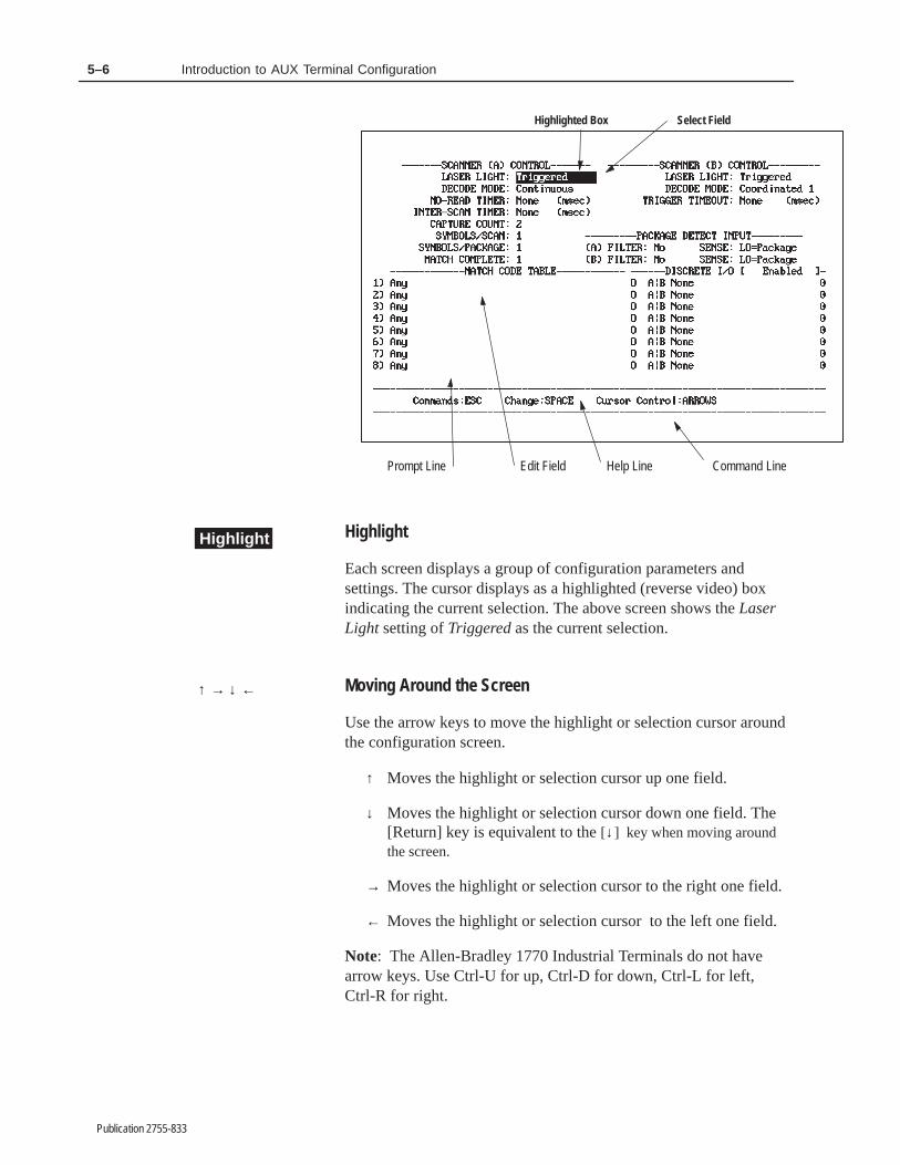
5–6 Introduction to AUX Terminal Configuration
Publication 2755-833
Prompt Line
Highlighted Box
Edit Field
Select Field
Help Line Command Line
Highlight
Each screen displays a group of configuration parameters andsettings. The cursor displays as a highlighted (reverse video) boxindicating the current selection. The above screen shows the LaserLight setting of Triggered as the current selection.
Moving Around the Screen
Use the arrow keys to move the highlight or selection cursor aroundthe configuration screen.
↑ Moves the highlight or selection cursor up one field.
↓ Moves the highlight or selection cursor down one field. The[Return] key is equivalent to the [↓ ] key when moving aroundthe screen.
→ Moves the highlight or selection cursor to the right one field.
← Moves the highlight or selection cursor to the left one field.
Note: The Allen-Bradley 1770 Industrial Terminals do not havearrow keys. Use Ctrl-U for up, Ctrl-D for down, Ctrl-L for left,Ctrl-R for right.
Highlight
↑ → ↓ ←

5–7Introduction to AUX Terminal Configuration
Publication 2755-833
Field Types
Each configuration parameter has a field associated with it thatshows the current setting. You can change the value or setting in anyfield. There are two main types of fields: select fields and edit fields.A third type, select/edit numeric field, is a hybrid of the other two.
Select Field
Select fields have a fixed group of settings from which you canchoose. For example, the Laser Light Mode is a select field and theavailable settings are On, Triggered, or Off. An example is shown onthe left.
Edit Field
Edit fields are data entry fields which allow you to enter strings ofcharacters. The length of the highlighted box determines the size ofthe field. An example is shown on the left. The three types of editfields are:
• ASCII character (decimal value 0 to 255)
ASCII fields display the decimal value followed by the ASCIIcharacter equivalent, for example: 013 = CR. You can enter:
– a decimal value; the software displays the ASCIIequivalent character
– an ASCII (non-numeric) character such as T; the softwaredisplays the decimal equivalent
– a [Return] when the field is empty; the software displaysNONE which means an ASCII value is not defined. Thedecimal value of 255 is interpreted as NONE
• numeric values
• text strings (including non-printable characters, see Appendix I)
Select/Edit Numeric Field
A select/edit numeric field, as its name implies, behaves as both aselect field and edit field. That is, you can either enter a numericvalue from the keyboard, or use the space bar to move through a listof available values.
Changing Fields
To change the contents of a select field, edit field, or select/editfield use these keys:

5–8 Introduction to AUX Terminal Configuration
Publication 2755-833
[Space] Advances through available settings in a select orselect/edit field or opens an edit field for changes.
Pressing [Space] in an edit field clears the contentsof the field and places you in edit mode. In editmode, the field is highlighted (displays in reversevideo) while you enter text.
[Backspace] Deletes the previous character in edit mode. Movesbackwards through the available settings in a selector select/edit field. This key is labeled [Delete] or[Rubout] on some computers. This key is not validin an edit field until the field is open.
[Tab] Opens edit field and puts the cursor in the firstposition without affecting the field contents. Ifpressed when field is already open, moves the cursorone place to the right. This allows you to change thecontents of edit fields without first clearing theircontents with the space bar. Opens select andselect/edit fields and selects next value.
[*] In a select or select edit field, pressing the asterisk(*) will set the field to its default value.
An asterisk in an unopened edit text field will openthe field and enter an asterisk in the first position.When pressed in an edit text field that is alreadyopen, the asterisk will behave like any otherprintable character.
Note: Most fields may be set to their default valueby pressing the [Space] key and then [Enter].Otherwise, press “ * ” (an asterisk) followed by[Enter].
[Return] In open fields, accepts the field selection or entryand closes the field. You must press [Return] toclose an open field before you can use the arrowkeys to move to another field. Moves the cursor tothe next field if applied to a closed field. This key islabeled [↵ ] or [Enter] on some computers.
[Esc] Cancels the selection change or edits (beforepressing [Return]) and restores the field to its initialcontents.
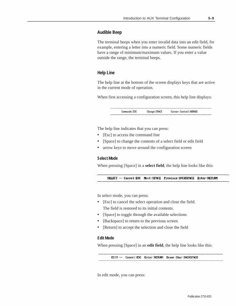
5–9Introduction to AUX Terminal Configuration
Publication 2755-833
Audible Beep
The terminal beeps when you enter invalid data into an edit field, forexample, entering a letter into a numeric field. Some numeric fieldshave a range of minimum/maximum values. If you enter a valueoutside the range, the terminal beeps.
Help Line
The help line at the bottom of the screen displays keys that are activein the current mode of operation.
When first accessing a configuration screen, this help line displays:
The help line indicates that you can press:
• [Esc] to access the command line
• [Space] to change the contents of a select field or edit field
• arrow keys to move around the configuration screen
Select Mode
When pressing [Space] in a select field, the help line looks like this:
In select mode, you can press:
• [Esc] to cancel the select operation and close the field.
The field is restored to its initial contents.
• [Space] to toggle through the available selections
• [Backspace] to return to the previous screen
• [Return] to accept the selection and close the field
Edit Mode
When pressing [Space] in an edit field, the help line looks like this:
In edit mode, you can press:

5–10 Introduction to AUX Terminal Configuration
Publication 2755-833
• [Esc] to cancel the edit operation and close the field.
The field is restored to its initial contents.
• [Return] to accept the entered data and close the field
• [Backspace] while editing to erase the last character
Command Line
Press [Esc] while in any configuration screen to access the commandline.
The command line displays with NEXT PAGE highlighted.
The following keys are active in the command line:
[Esc] Exits configuration mode and returns to the SelectOperation menu.
[Return] Accepts the highlighted command and performs theoperation.
[Space] Toggles through options in the command line.
[→] [←] Moves highlight one command to the right or left.
Command Summary
NEXT PAGE Displays the next configuration screen. The screensdisplay in the order below:
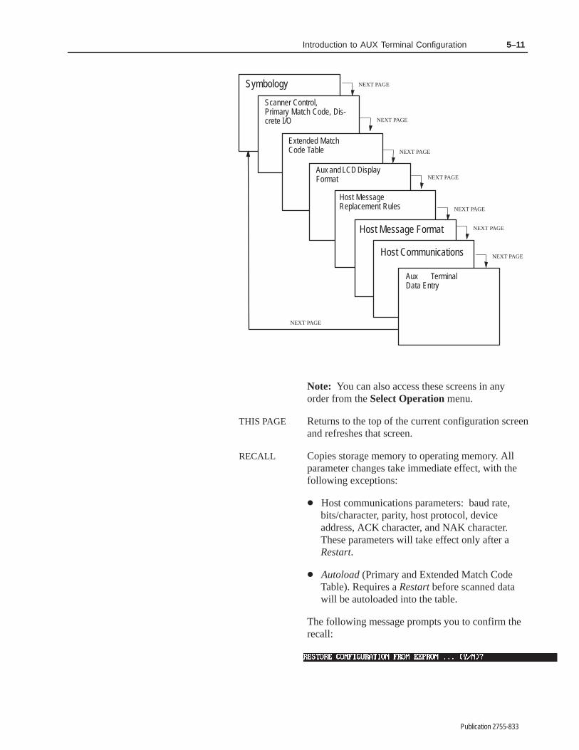
5–11Introduction to AUX Terminal Configuration
Publication 2755-833
NEXT PAGE
NEXT PAGE
NEXT PAGE
NEXT PAGE
NEXT PAGE
NEXT PAGE
NEXT PAGE
Symbology
Extended MatchCode Table
Aux and LCD DisplayFormat
Host MessageReplacement Rules
Scanner Control,Primary Match Code, Dis-crete I/O
Host Message Format
NEXT PAGE
Aux TerminalData Entry
Host Communications
Note: You can also access these screens in anyorder from the Select Operation menu.
THIS PAGE Returns to the top of the current configuration screenand refreshes that screen.
RECALL Copies storage memory to operating memory. Allparameter changes take immediate effect, with thefollowing exceptions:
� Host communications parameters: baud rate,bits/character, parity, host protocol, deviceaddress, ACK character, and NAK character.These parameters will take effect only after aRestart.
� Autoload (Primary and Extended Match CodeTable). Requires a Restart before scanned datawill be autoloaded into the table.
The following message prompts you to confirm therecall:

5–12 Introduction to AUX Terminal Configuration
Publication 2755-833
Press [N] or [Esc] to cancel the operation and returnto the Select Operation menu. Press [Y] to recallthe values from storage memory. The recalledconfiguration will then control decoder operations.
SAVE Saves the configuration currently in operatingmemory to storage memory. The Save commanddoes not alter the current operation of the decoder.The following message prompts you to confirm thesave operation.
Press [N] or [Esc] to cancel the operation and returnto the Select Operation menu. Press [Y] to save theconfiguration to storage memory.
DEFAULT Copies the factory default configuration parametersinto operating memory. All parameters take effectimmediately, with the following exceptions:
� Host communications parameters: baud rate,bits/character, parity, host protocol, deviceaddress, ACK character, and NAK character.These parameters will take effect only after aRestart.
When you select Default, the following confirmationmessage will appear:
Press [N] or [Esc] to cancel the operation and returnto the Select Operation menu. Press [Y] to restorethe factory defaults in storage memory to operatingmemory. This operation has no effect on anyconfiguration parameters previously saved to storagememory with the Save command. The factorydefaults are listed in Appendix B.
!ATTENTION: It is good practice to save yourconfiguration once the required host communicationsparameters have been set. Doing so assures you willretain those parameter settings even after lengthyperiods without power.

������ �
Publication 2755-833
� ������� �� ���� ��
Option 1 on the Select Operation menu accesses the Symbologyconfiguration screen. Use this function to select symbologies fordecoding and to define the operating parameters to use duringdecoding. The screen is displayed with the first field highlighted.
The default settings are displayed the first time you access thisscreen. Make changes appropriate for your application. If the factorydefaults are satisfactory, you can return to the Select Operationmenu by pressing [Esc] twice.
The parameters on this screen:
• Enable symbologies for decoding
• Enable specific length checking, which serves two purposes:
– provides data integrity for variable length symbologies byprotecting against short reads. The decoder will only decodebar code symbols that contain the exact number of charactersspecified in the length fields. Especially useful for Interleaved2 of 5 when check characters are not being used.
– optimizes operations by allowing the decoder to select scansfor decoding from several labels with different lengths. Forexample, the decoder can select the 6 character code from acarton that has 14, 6, and 4 character codes
• Enable supplements for UPC/EAN symbologies
• Enable verification of guard bars with Interleaved 2-of-5 symbols
• Adjust and set the quiet zone ratio (if necessary)
• Configure parameters for Pharma–Code labels.
Configure Symbology

6–2 Configuration: Symbology
Publication 2755-833
The decoder will auto discriminate between multiple symbologies.For optimum performance, enable only those symbologies and codelengths you intend to use.
The following pages define each symbology parameter along withthe field type and possible values. The default value is shown in boldletters.
Code 39
Field Type Options
Select NoYes
Enables/disables decoding of Code 39 bar code labels. The default ofYes (except on Pharma-Code decoders) enables decoding of thissymbology. Select No to disable decoding.
Code 39 Specific Lengths
Field Type Options
Edit Numeric 0 through 64 (0)
Sets length checking for Code 39 bar code labels. The default is 0,which means the decoder does not check lengths.
You can specify up to 8 code lengths (maximum of 64 characters).The code length includes the check character, but not the startand stop characters. If you specify a code length other than 0, thedecoder will only decode labels with the number of charactersspecified.
Important: Enter specific lengths starting with the leftmost blankfield. Specific lengths entered to the right of a blank field areignored.
Correct Incorrect
15 is to the right of a blankfield and will be ignored.

6–3Configuration: Symbology
Publication 2755-833
Code 39 Check Character
Field Type Options
Select NoYes
Controls whether the decoder is required to compute and verify acode check character for Code 39 bar codes. The code checkcharacter ensures that the data is read correctly. The default is No,which means the decoder treats all decoded characters as data.
The Code 39 check character is computed as a Modulus 43 sum ofall characters value as specified in the AIM specification USS-39.
Include Code 39 Check Character
Field Type Options
Select NoYes
Controls whether the code 39 check character computed by thedecoder is included in the message sent to the host. The default isNo, which means the Code 39 check character is not sent to the host.
Interleaved 2-of-5
Field Type Options
Select NoYes
Enables/disables decoding of Interleaved 2-of-5 bar code labels. Thedefault of No disables decoding of this symbology. Select Yes toenable decoding.
Interleaved 2-of-5 Specific Lengths
Field Type Options
Edit Numeric Even numbers2 through 64 (0)
Sets length checking for Interleaved 2-of-5 bar code labels. Thedefault is 0, which means the decoder does not check lengths.
You can specify up to 8 code lengths (maximum of 64 characters).Only even numbers (2-64) are allowed. The code length includesthe check character, but not the start and stop characters. If youspecify a code length other than 0, the decoder will only decodelabels with the number of characters specified.

6–4 Configuration: Symbology
Publication 2755-833
We recommend that you enter specific lengths for Interleaved 2-of-5labels. Otherwise, a partial scan of symbols could result in a validshorter read.
The decoder will ignore 2 character Interleaved 2-of-5 labels unlessyou enter a specific length of 2.
Interleaved 2-of-5 Check Character
Field Type Options
Select NoYes
Controls whether the decoder is required to compute and verify acode check character for Interleaved 2 of 5 bar codes. The codecheck character ensures that the data is read correctly. The default isNo, which means the decoder treats all decoded characters as data.
The Interleaved 2 of 5 character is computed as a Modulus 10 sum ofall characters value as specified in the AIM specification USS-I 2/5.
Include Interleaved 2-of-5 Check Character
Field Type Options
Select NoYes
Controls whether the Interleaved 2 of 5 check character computed bythe decoder is included in the message sent to the host. The default isNo, which means the Interleaved 2 of 5 check character is not sent.
Interleaved 2-of-5 Guard Bars
Field Type Options
Select NoYes
Controls verification of the presence of guard bars on Interleaved2-of-5 symbols. The default of No results in no verification. SelectYes to activate guard bar verification.

6–5Configuration: Symbology
Publication 2755-833
Codabar
Field Type Options
Select NoYes
Enables/disables decoding of Codabar labels. The default of Nodisables decoding of this symbology. Select Yes to enable decoding.
Codabar Specific Lengths
Field Type Options
Edit Numeric 0 through 64 (0)
Sets length checking for Codabar labels. The default is 0, whichmeans the decoder does not check lengths.
You can specify up to 8 code lengths (maximum of 64 characters).The code length includes the check character and the start andstop characters. If you specify a code length other than 0, thedecoder will only decode labels with the number of charactersspecified.
Codabar Check Character
Field Type Options
Select NoYes
Controls whether the decoder is required to compute and verify acode check character for Codabar bar codes. The code checkcharacter ensures that the data is read correctly. The default is No,which means the decoder treats all decoded characters as data.
The Codabar character is computed as a Modulus 16 sum of allcharacters value as specified in the AIM specification USS-Codabar.
Include Codabar Check Character
Field Type Options
Select NoYes
Controls whether the Codabar check character computed by thedecoder is included in the message sent to the host. The default isNo, which means the Codabar check character is not sent.

6–6 Configuration: Symbology
Publication 2755-833
Code 128
Field Type Options
Select NoYes
Enables/disables decoding of Code 128 labels. The default of Nodisables decoding of this symbology. Select Yes to enable decoding.
Code 128 Specific Lengths
Field Type Options
Edit Numeric 0 through 64 (0)
Sets length checking for Code 128 labels. The default is 0, whichmeans the decoder does not check lengths.
You can specify up to 8 code lengths (maximum of 64 characters).The code length does not include the check character or the startand stop characters.① If you specify a code length other than 0, thedecoder will only decode labels with the number of charactersspecified.
The decoder uses the specific length parameter in three ways:
• The decoder discards decoded symbols with lengths that do notmatch the specific length parameter
This allows you to filter out all decoded symbols except thosethat have a specific length that appears in the specific lengthtable.
• The decoder uses it to determine if the number of bar to spacetransitions that occur during a scan is appropriate for thesymbologies and specific length values
Scans that occur in the absence of a symbol or part of a symbolare not valid, and therefore result in extra processing overhead forthe decoder. The decoder discards these scans before themicroprocessor sees them.
• Once the microprocessor sees a scan, it uses the specific lengthparameter to search within the symbol for a valid number of barto space transitions
① The decoder will ignore Code 128 FNC2, FNC3, and FNC4 characters regardless of the Code 128 FNCharacter setting. FNC2, FNC3, and FNC4 are also ignored by the specific length parameter.
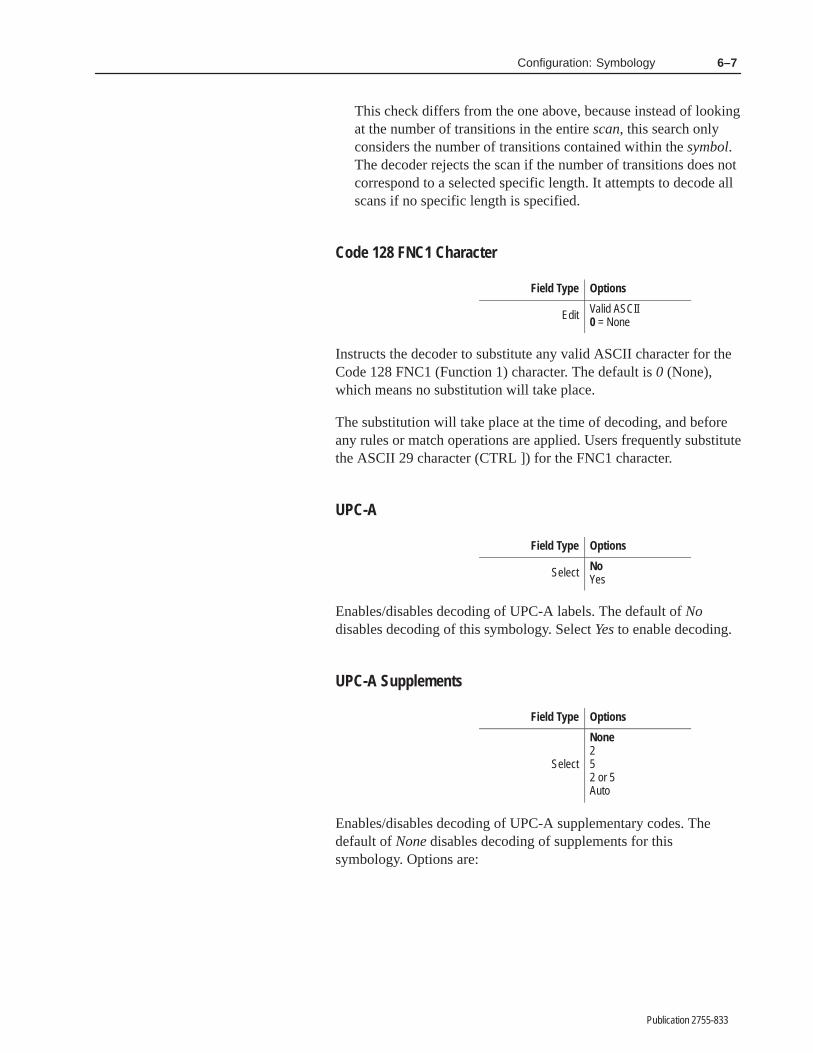
6–7Configuration: Symbology
Publication 2755-833
This check differs from the one above, because instead of lookingat the number of transitions in the entire scan, this search onlyconsiders the number of transitions contained within the symbol.The decoder rejects the scan if the number of transitions does notcorrespond to a selected specific length. It attempts to decode allscans if no specific length is specified.
Code 128 FNC1 Character
Field Type Options
Edit Valid ASCII0 = None
Instructs the decoder to substitute any valid ASCII character for theCode 128 FNC1 (Function 1) character. The default is 0 (None),which means no substitution will take place.
The substitution will take place at the time of decoding, and beforeany rules or match operations are applied. Users frequently substitutethe ASCII 29 character (CTRL ]) for the FNC1 character.
UPC-A
Field Type Options
Select NoYes
Enables/disables decoding of UPC-A labels. The default of Nodisables decoding of this symbology. Select Yes to enable decoding.
UPC-A Supplements
Field Type Options
Select
None252 or 5Auto
Enables/disables decoding of UPC-A supplementary codes. Thedefault of None disables decoding of supplements for thissymbology. Options are:

6–8 Configuration: Symbology
Publication 2755-833
None Disables decoding of supplementary codes.2 Enables decoding of 2 character supplementary codes.5 Enables decoding of 5 character supplementary codes.
2 or 5 Enables decoding of 2 or 5 character supplementary codes.
Auto Enables decoder to auto discriminate supplementary codes (None, 2 or 5) on label①
① The Auto Selection allows you to mix labels without supplements with labels containing 2 or 5 digitsupplements. The supplements are often a different size than the primary symbol. Therefore, it iscritical that both the primary symbol and the supplement be present when the decoder istriggered. If the decoder does not detect the supplement, the primary symbol is sufficient toproduce a valid scan. The Auto selection is not recommended when the Decode Mode is set toContinuous.
If you select 2, 5, or 2 or 5, the decoder must decode both theprimary label and the supplement to produce a valid scan.
UPC-E
Field Type Options
Select NoYes
Enables/disables decoding of UPC-E labels. The default of Nodisables decoding of this symbology. Select Yes to enable decoding.
UPC-E Supplements
Field Type Options
Select
None252 or 5Auto
Enables/disables decoding of UPC-E supplementary codes. Thedefault of None disables decoding of supplements for thissymbology. Options are:
None Disables decoding of supplementary codes.2 Enables decoding of 2 character supplementary codes.5 Enables decoding of 5 character supplementary codes.
2 or 5 Enables decoding of 2 or 5 character supplementary codes.
Auto Enables decoder to auto discriminate supplementary codes (None, 2 or 5) on label①
① The Auto Selection allows you to mix labels without supplements with labels containing 2 or 5 digitsupplements. The supplements are often a different size than the primary symbol. Therefore, it iscritical that both the primary symbol and the supplement be present when the decoder istriggered. If the decoder does not detect the supplement, the primary symbol is sufficient toproduce a valid scan. The Auto selection is not recommended when the Decode Mode is set toContinuous.
If you select 2, 5, or 2 or 5, the decoder must decode both theprimary label and the supplement to produce a valid scan.
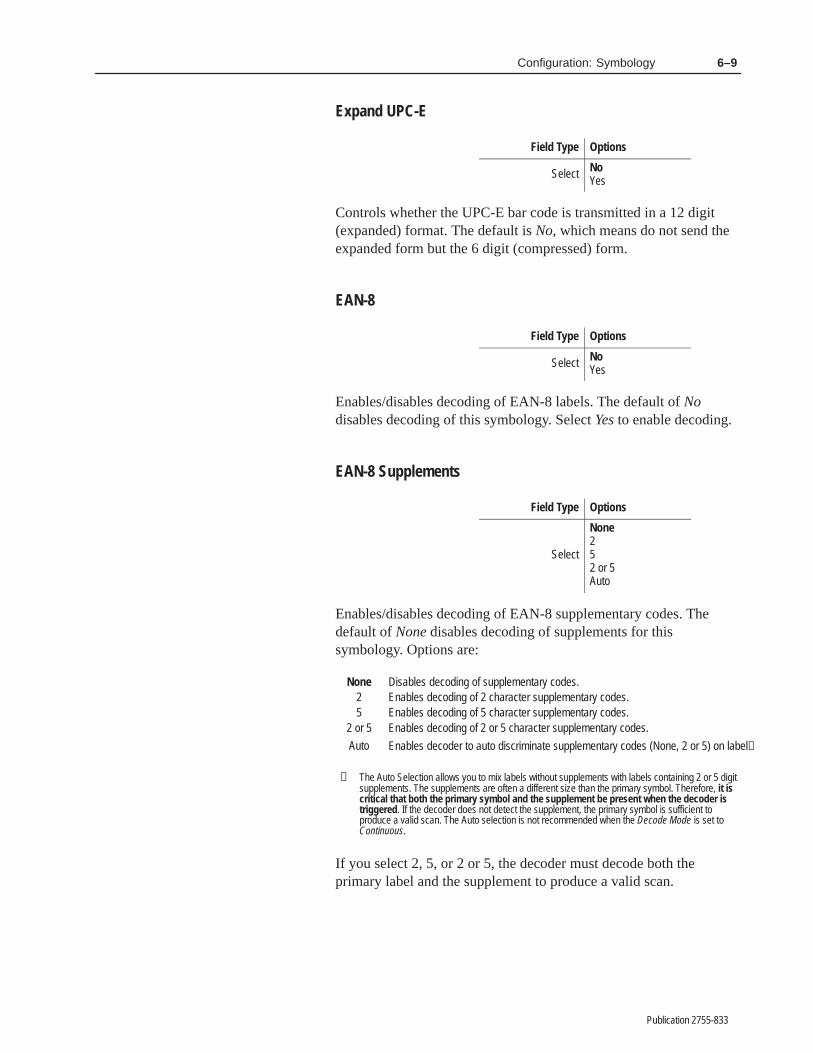
6–9Configuration: Symbology
Publication 2755-833
Expand UPC-E
Field Type Options
Select NoYes
Controls whether the UPC-E bar code is transmitted in a 12 digit(expanded) format. The default is No, which means do not send theexpanded form but the 6 digit (compressed) form.
EAN-8
Field Type Options
Select NoYes
Enables/disables decoding of EAN-8 labels. The default of Nodisables decoding of this symbology. Select Yes to enable decoding.
EAN-8 Supplements
Field Type Options
Select
None252 or 5Auto
Enables/disables decoding of EAN-8 supplementary codes. Thedefault of None disables decoding of supplements for thissymbology. Options are:
None Disables decoding of supplementary codes.2 Enables decoding of 2 character supplementary codes.5 Enables decoding of 5 character supplementary codes.
2 or 5 Enables decoding of 2 or 5 character supplementary codes.
Auto Enables decoder to auto discriminate supplementary codes (None, 2 or 5) on label①
① The Auto Selection allows you to mix labels without supplements with labels containing 2 or 5 digitsupplements. The supplements are often a different size than the primary symbol. Therefore, it iscritical that both the primary symbol and the supplement be present when the decoder istriggered. If the decoder does not detect the supplement, the primary symbol is sufficient toproduce a valid scan. The Auto selection is not recommended when the Decode Mode is set toContinuous.
If you select 2, 5, or 2 or 5, the decoder must decode both theprimary label and the supplement to produce a valid scan.

6–10 Configuration: Symbology
Publication 2755-833
EAN-13
Field Type Options
Select NoYes
Enables/disables decoding of EAN-8 labels. The default of Nodisables decoding of this symbology. Select Yes to enable decoding.
EAN-13 Supplements
Field Type Options
Select
None252 or 5Auto
Enables/disables decoding of EAN-13 supplementary codes. Thedefault of None disables decoding of supplements for thissymbology. Options are:
None Disables decoding of supplementary codes.2 Enables decoding of 2 character supplementary codes.5 Enables decoding of 5 character supplementary codes.
2 or 5 Enables decoding of 2 or 5 character supplementary codes.
Auto Enables decoder to auto discriminate supplementary codes (None, 2 or 5) on label①
① The Auto Selection allows you to mix labels without supplements with labels containing 2 or 5 digitsupplements. The supplements are often a different size than the primary symbol. Therefore, it iscritical that both the primary symbol and the supplement be present when the decoder istriggered. If the decoder does not detect the supplement, the primary symbol is sufficient toproduce a valid scan. The Auto selection is not recommended when the Decode Mode is set toContinuous.
If you select 2, 5, or 2 or 5, the decoder must decode both theprimary label and the supplement to produce a valid scan.
Enable Pharma-Code Symbology (Pharma-Code Decoders Only)
Field Type Options
Select NoYes
Enables decoding of Pharma-Code symbols. The default of Yesenables decoding for this symbology. Select No to disable decoding

6–11Configuration: Symbology
Publication 2755-833
Note: We recommend starting with the default settings for allPharma-Code parameters except Minimum Number of Bars andDecode Direction, which must be determined by your application.The complex interrelationships among other Pharma-Code optionsmake them best suited for use only by experienced Pharma-Codeusers in unusual instances when the default values do not provideacceptable results.
Quiet Zone Ratio (All Decoders)
Field Type Options
Edit Numeric 4 through 10 (5)
Specifies the ratio of the width of the clear space before the first barto the width of the first bar, or the width of the clear space after thelast bar to the width of the last bar; whichever is smaller. Valid quietzone ratio values are 4 to 10. The default is 5. The default value forthis parameter has been optimized for most applications, and itis unlikely you will ever have a reason to change it.
AB
If scan direction is AClear Space Width
1st Bar Width (Wide Bar)= 5
If scan direction is BClear Space Width
1st Bar Width (Narrow Bar)= 10
For this example:
Quiet Zone Quiet Zone
Wide BarNarrow Bar
Space
The decoder uses the quiet zone to determine the necessary clearspace on both sides of the symbol. A symbol not preceded by anadequate quiet zone is ignored.➀ The quiet zone after the bars andspaces of a symbol indicates the end of data. If you specify a quietzone ratio that is too small, the decoder may interpret a space withinthe symbol as the end of the symbol, resulting in no-reads ormisreads. A general rule to use is:
Maximum Space Width in Symbol
Minimum Narrow Bar Width Quiet Zone RatioWidth of the Smallest Quiet Zone
Maximum Wide Bar Width
① If the Quiet Zone is found to be inadequate, the decoder will examine the symbol further to attempt a dWe recommend, however, that all labels be printed within specified limits.

6–12 Configuration: Symbology
Publication 2755-833
A typical quiet zone value for the Pharma-Code symbology is 5.
Space Tolerance (Pharma-Code Decoders Only)
Field Type Options
Edit 5 through 40 (15)Ignore
Defines the percent difference (in width) between the narrowest andwidest space elements of the Pharma-Code symbol. Space toleranceis expressed mathematically as:
(Widest Space + Narrowest Space)
2
(Widest Space – Narrowest Space)
x 100% = % Space Tolerance
Select a value that is greater than the worst case tolerance to preventno-reads.
Valid percent values are 5 to 40, or Ignore. If set to Ignore anyamount of space tolerance is allowed within the symbol. The defaultvalue is 15 (15%). The default value for this parameter has beenoptimized for most applications, and it is unlikely you will everhave a reason to change it.
The decoder will reject a symbol if two spaces within the symboldiffer in width by more than the space tolerance value. Select Ignoreto prevent the decoder from rejecting a symbol based on widthdifferences between spaces.
Bar Tolerance (Pharma-Code Decoders Only)
Field Type Options
Edit 5 through 40 (15)Ignore
Defines the percent difference (in width) between two bars of asymbol that have the same nominal width but the largest widthdifference. There are two bar tolerances since Pharma-Code symbolshave wide and narrow bars. Bar tolerance is expressedmathematically as:

6–13Configuration: Symbology
Publication 2755-833
(Widest
x 100% = % Bar Tolerance
Wide Bar – Narrowest Wide Bar )
(Widest Wide Bar + Narrowest Wide Bar )
2
OR
(Widest
x 100% = % Bar Tolerance
Narrow
2
Bar – Narrowest Narrow Bar)
(Widest Narrow Bar + Narrowest Narrow Bar)
Select a value that is greater than the worst case tolerance to preventno-reads.
Valid bar tolerance values are 5 to 40, or Ignore. The Ignore valueallows any amount of tolerance between bars of the same nominalwidth. The default value is 15 (15%). The default value for thisparameter has been optimized for most applications, and it isunlikely you will ever have a reason to change it.
The decoder will reject a symbol if the width of two bars of the samenominal width differs by more than the bar tolerance value. SelectIgnore to prevent the decoder from rejecting a symbol based onwidth differences between bars of the same nominal width.
Minimum Number of Bars (Pharma-Code Decoders Only)
Field Type Options
Edit 3 through 12 (5)
Specifies the least number of bars that must be present within aPharma-Code symbol for the decoder to perform a decode. Possiblevalues are 3 to 12. The default is 5.
If the Code Verification List contains values, the decoder will ignorethe minimum bar setting and decode only those symbols that havevalues in the list.
If the Code Verification List has no values, the decoder will reject allsymbols that contain fewer bars than the minimum bar setting.

6–14 Configuration: Symbology
Publication 2755-833
Decode Direction (Scanner A or B) (Pharma-Code Decoders Only)
Field Type Options
Select ForwardReverse
Sets the direction the decoder uses to decode a scanned label.Direction values are either Forward or Reverse. The default isForward.
The decoder uses the decode direction to determine the leastsignificant bar of a symbol. The examples below show how aPharma-Code label is decoded depending on the direction.
Example 1: The decode direction is set to forward. The decodedirection fixes the position of the least significant bar (regardless ofscan direction). The decoded value is 94.
94
Least Significant BarMost Significant Bar
Decode Direction = ForwardDecoded Value = 94
Scan Direction
Decode Direction
Example 2: The decode direction is set to reverse. The decodedirection fixes the position of the least significant bar. The decodedvalue is 125.
125
Most Significant BarLeast Significant Bar
Decode Direction = ReverseDecoded Value = 125
Scan Direction
Decode Direction
Wide to Narrow Bar Ratio (Pharma-Code Decoders Only)
Field Type Options
Edit 2 through 4 (2)Midrange
Specifies the minimum ratio of the widest bar to the narrowest barwithin a symbol.
Valid settings are 2 to 4, or midrange. The default is 2. The defaultvalue for this parameter has been optimized for mostapplications, and it is unlikely you will ever have a reason tochange it.
If the setting is 2 to 4, the decoder will reject symbols whose wide tonarrow bar ratio is less than the parameter setting.
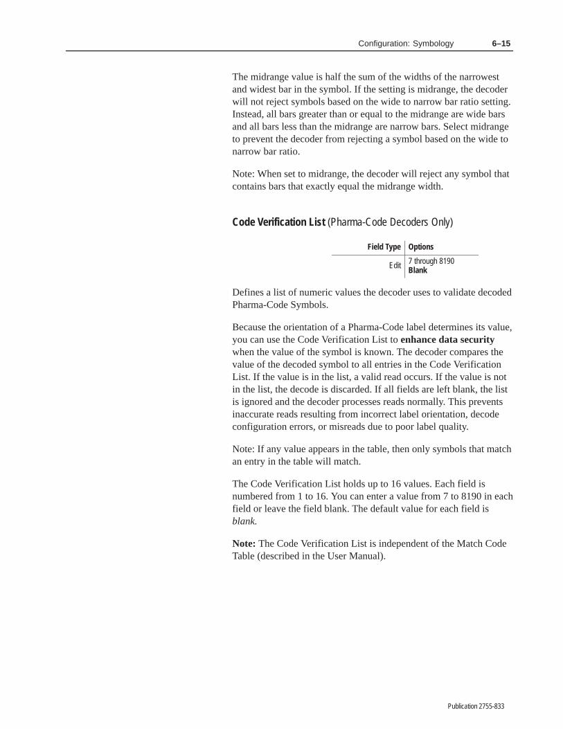
6–15Configuration: Symbology
Publication 2755-833
The midrange value is half the sum of the widths of the narrowestand widest bar in the symbol. If the setting is midrange, the decoderwill not reject symbols based on the wide to narrow bar ratio setting.Instead, all bars greater than or equal to the midrange are wide barsand all bars less than the midrange are narrow bars. Select midrangeto prevent the decoder from rejecting a symbol based on the wide tonarrow bar ratio.
Note: When set to midrange, the decoder will reject any symbol thatcontains bars that exactly equal the midrange width.
Code Verification List (Pharma-Code Decoders Only)
Field Type Options
Edit 7 through 8190Blank
Defines a list of numeric values the decoder uses to validate decodedPharma-Code Symbols.
Because the orientation of a Pharma-Code label determines its value,you can use the Code Verification List to enhance data securitywhen the value of the symbol is known. The decoder compares thevalue of the decoded symbol to all entries in the Code VerificationList. If the value is in the list, a valid read occurs. If the value is notin the list, the decode is discarded. If all fields are left blank, the listis ignored and the decoder processes reads normally. This preventsinaccurate reads resulting from incorrect label orientation, decodeconfiguration errors, or misreads due to poor label quality.
Note: If any value appears in the table, then only symbols that matchan entry in the table will match.
The Code Verification List holds up to 16 values. Each field isnumbered from 1 to 16. You can enter a value from 7 to 8190 in eachfield or leave the field blank. The default value for each field isblank.
Note: The Code Verification List is independent of the Match CodeTable (described in the User Manual).

������ �
Publication 2755-833
�������� ����� �� ������������ ��� �� � ��� � ������������ ��
Option 2 on the Select Operation configuration screens. Use thisfunction to configure scanner control, match codes, and discrete I/Ooperations. The screen displays with the first field highlighted.
The factory defaults are displayed the first time you access thisscreen. Make changes appropriate for your application. If the factorydefaults are satisfactory, you can return to the Select Operationmenu by pressing [Esc] twice.
The parameters are grouped by function on the screen. The followingpages describe each group of parameters.
Scanner A Control Parameters
These parameters control the operation of Scanner A. Eachparameter is defined below. The options for each parameter aresummarized in a table, and explained more fully in the text. Thedefault setting for each parameter is displayed in bold letters in thetable.
Scanner Control, PrimaryMatch Code Table,Discrete I/O

7–2 Configuration: Scanner Control, Primary Match Table, Discrete I/O
Publication 2755-833
Laser Light (Scanners A and B)
Field Type Options
SelectOnTriggeredOff
Determines whether the Scanner A laser is on continuously, turns onand off with the trigger, or is off regardless of the trigger. Usetriggered mode with slower package rates to extend the life of yourlaser.
This parameter also affects Scanner B when it is set to operate incoordinated mode with Scanner A. See Scanning Mode underScanner B Control.
On The scanner scans continuously.
Triggered The scanner scans only when receiving a triggerfrom a package detector, host, or internal timer. Thescanner continues scanning until an end triggercondition occurs.
Off Turns the scanner laser off. Use this setting as asafety precaution during decoder maintenance ortroubleshooting.
Important: It is important that you understand the following termsbefore proceeding.
• valid scan
• valid symbol
• valid read
• valid package
• no-read
See Glossary for definitions.
Decode Mode
Field Type Options
Select
ContinuousContinuous/UniquePackage DetectHostInternal Timer
Determines how the decoder starts and stops decoding. Thisparameter affects Scanner A, or Scanner A and B when both areoperating in coordinated mode. (See Scanning Mode under ScannerB Control.)

7–3Configuration: Scanner Control, Primary Match Table, Discrete I/O
Publication 2755-833
Continuous The decoder continuously attempts to decode everyscan from the scanner. There is no start and stopcontrol.
The continuous mode of operation is useful duringinitial setup to determine the optimum location ofthe scanner relative to the bar code labels. (Use aSymbols Per Package value of 1 for setup.)
The no-read condition does not exist in this mode.
Continuous/Unique The decoder continuously attempts to decodeevery scan from the scanner. The decoder discardsvalid reads that are identical to the previous validread. The decoder does not process data (send tohost or activate appropriate match codes) until a newvalid read is decoded.
A valid package in continuous/unique mode is avalid read that is different from the previous validpackage.
The no-read condition does not exist in this mode.
Host A start scan command from a host device triggersthe decoder to start decoding.
Note: Refer to the section on host communicationsfor additional information on the start and stop scancommands.
Package Detect A package detect signal triggers decoding on andoff. The package detect is typically an externalpresence sensor or the trigger of a hand-held laserscanner.
The package detect signals the arrival and departureof a package.
Internal Timer This mode uses the No-Read Timer as a triggersource. A set time interval triggers decoding on andoff. The No-Read Timer determines the timeinterval.

7–4 Configuration: Scanner Control, Primary Match Table, Discrete I/O
Publication 2755-833
Figure 7.1 Internal timer trigger
ON
OFF
X Y
X = Y = No-Read Timer value (in milliseconds)
Minimum value = 10 msecMaximum value = 9999 msec➀
Resolution = 5 msec
A no-read occurs if the timer expires before a validpackage occurs.
The Internal Timer decode mode is useful duringinitial setup to simulate the package detect signal.
Note: When Scanner B is operating independently from Scanner A,its decode mode is always either Package Detect or Host.
No-Read Timer
Field Type Options
Edit 10 through 9999 or 0
Specifies the length of time the decoder will try to decode a labelwhen triggered by a host command or package detector. The timerstarts when the decoder is triggered. If a valid package does notoccur within the specified time (Symbols/Package setting is notsatisfied), a no-read occurs.
The default of 0 disables the timer. To set the timer, enter a numberbetween 10 and 9999.➀ Select a value that allows the decoder enoughtime to read an entire package or a no-read will occur.
Note: When the decode mode is set to internal timer, the no-readtimer functions as a trigger source. The trigger remains on until theno-read timer expires. See Internal Timer under Decode Mode.
➀ ATTENTION: Set output durations in multiples of 5 milliseconds. Actual output will have a worst-case precisionof +0 to –5 milliseconds, varying with the timing of the output. Durations that are not set in multiples of 5milliseconds will be rounded up to the nearest multiple of 5 and function within the same +0 to –5 millisecondprecision.
For example, a setting of 25 milliseconds will result in a duration of from 20 to 25 milliseconds. A setting of 23milliseconds will result in the same duration range.

7–5Configuration: Scanner Control, Primary Match Table, Discrete I/O
Publication 2755-833
Inter-Scan Timer
Field Type Options
Edit 10 through 9999 or 0
Disables decoding for a set time interval after a valid read. Thedefault is 0, which disables the timer. The Inter-Scan Timer is validin both continuous and triggered modes of operations.
You can use the Inter-Scan Timer to:
• provide a delay between decodes to enable multiple labels, thatare not necessarily unique, to be read within the same package
• enable multiple decodes of the same label for verificationpurposes
The Inter-Scan Timer accepts a value between 10 and 9999.➀
Important: To ensure that package labels are read before theNo-Read Timer expires, set the Inter-Scan Timer to a value that isless than the No-Read Timer setting.
A valid read starts the timer. See Figure 5.2. The decoder decodes ascan within Field #1, which starts the Inter-Scan Timer andimmediately stops decoding. The decoder waits for the timer toexpire (or timeout) to resume decoding.
Use the following equations to create a delay between decodes:
W (cm or inches) x 1000 (msec/sec)
Line Speed (cm/sec or inches/sec)Approximate Inter-Scan Timer Value (msec)=
Equation 1:
Equation 2: Maximum Inter-Scan Timer Value
S (cm or inches) x 1000 (msec/sec)
Line Speed (cm/sec or inches/sec)Approximate Inter-Scan Timer Value (msec)=
Minimum Inter-Scan Timer Value
You may have to experiment with several settings since factors suchas label quality determine when the first read occurs.
➀ ATTENTION: Set output durations in multiples of 5 milliseconds. Actual output will have a worst-case precisionof +0 to –5 milliseconds, varying with the timing of the output. Durations that are not set in multiples of 5milliseconds will be rounded up to the nearest multiple of 5 and function within the same +0 to –5 millisecondprecision.
For example, a setting of 25 milliseconds will result in a duration of from 20 to 25 milliseconds. A setting of 23milliseconds will result in the same duration range.

7–6 Configuration: Scanner Control, Primary Match Table, Discrete I/O
Publication 2755-833
Figure 7.2 Inter-scan timer
Direction of Travel
Field #1 Field #2
Scan
Lin
e
S
W
D D =
W =
S =
Distance traveled during Inter-Scan Timer.
Width of label.
Distance between start of field #1 field #2.
The label orientation must be such that distance D is ≤ S for thescanner to scan all of Field #2. The line speed must be constant.
Set the Inter-Scan Timer to a value between the minimum andmaximum values to prevent additional decodes of Field #1, whileallowing all of Field #2 to be scanned.
To allow multiple reads of a single symbol for verification purposes,set the Inter-Scan Timer to a value that is less than equation 1.
Capture Count
Field Type Options
Select/Edit 1 through 8, or V2
Specifies the number of identical valid scans that must be decodedbefore a read is considered valid. The default is 2, which means thecapture count is not satisfied until two sequential, identical, validscans are decoded. A capture count of 2 is appropriate for mostapplications.
To specify a different capture count, select a value between 1 and 8,or V. V (for Verify) requires that each symbol in a bar code mustmatch an entry in the primary match code table to produce a validread.
The “V” capture count is useful in high speed verificationapplications, where the value of the symbol is known. By loading theexpected value into a match code table, the decoder only needs toacquire one valid scan matching the expected values to produce avalid read.

7–7Configuration: Scanner Control, Primary Match Table, Discrete I/O
Publication 2755-833
The decoder interprets a scanned label in one of three ways.
• Valid Scan
Sufficient valid symbols have been decoded to satisfy theSymbols/Scan parameter.
• Undecodable Scan
The scanned data does not correspond to a valid pattern withinthe selected symbologies.
• Misread or Substitution Error
Smudges, stray marks, voids, or print errors (resulting in wider ornarrower bars and spaces) may result in a pattern that is validwithin an enabled symbology that is not representative of theintended data.
The capture count reduces misreads by requiring the decoder to readlabels multiple times before producing a valid read.
Symbologies that are not self-checking (do not use start and stopcharacters or check characters) are more susceptible to misreads. Forexample, Interleaved 2-of-5 without check characters is notself-checking.
Setting the capture count too high may result in excessive no-reads,particularly when the number of scans crossing the label in a triggerperiod is low (5 - 10). Set the capture count to a value no greater thanhalf the number of expected scans crossing the label in a triggerperiod.
Symbols / Scan
Field Type Options
Select/Edit 1–6, Any1
Specifies the number of bar code symbols that must be present in ascan for a valid read. The default is 1.
On a single scan (movement of laser beam from one side to another),the decoder can decode up to 6 successive bar code symbols. Validsettings for this parameter include 1, 2, 3, 4, 5, 6 or Any.
If you select Any, the decoder looks for up to 6 symbols. Thedecoder will ignore any damaged symbols it encounters.
Select Any for those applications where the number of symbolsvaries or cannot be controlled. For all other applications specify anumber.

7–8 Configuration: Scanner Control, Primary Match Table, Discrete I/O
Publication 2755-833
Important: If you select Any and the decoder is operating in atriggered mode, the symbols within each label must be unique. Thedecoder interprets identical symbols as duplicates and ignores thesecond symbol.
Symbols/Package
Field Type Options
Select/Edit 1–161
Specifies the number of valid symbols that must be decoded toproduce a valid package. The default is 1. You can enter a numericvalue between 1 and 16.
If the Symbols/Package setting is satisfied, a valid read occurs. If theSymbols/Package setting is not satisfied, a no-read occurs for thatpackage as well as for each symbol not read.
Match Complete
Field Type Options
Select/Edit 1–161
Specifies the number of times that symbols on a package must matchentries in the match code table before a Match Complete conditionoccurs. You can enter a value from 1 to 16. The default is 1, whichmeans at least one symbol on a package must match an entry in thematch code table.
Match Complete is one of ten output conditions that can activate anoutput. See the Output Condition parameter.
Note: The match complete count does not have to equal theSymbols/Package setting. However, the match complete count mustbe less than or equal to the Symbols/Package setting for a matchcomplete condition to occur.
Scanner B Control Parameters
These parameters control the operation of Scanner B. Eachparameter is defined below. The options for each parameter aresummarized in a table, and explained more fully in the text. Thedefault setting for each parameter is displayed in bold letters in thetable.

7–9Configuration: Scanner Control, Primary Match Table, Discrete I/O
Publication 2755-833
Laser Light
Refer to Laser Light under Scanner A Parameters earlier in thissection for information on Scanner B laser light control.
Decode Mode
Field Type Options
Select
Coordinated 1Coordinated 2Package DetectHost
Sets the decode mode for Scanner B. The options are Coordinated 1,Coordinated 2, Package Detect, and Host. The default isCoordinated 1.
If you set the scanning mode to either Coordinated mode, Scanner Boperates in concert with Scanner A, and both scanners use the triggerspecified for Scanner A. The Trigger Timeout parameters is notused when Scanner B operates in coordinated mode.
If you use one of the independent decode modes (either Host orPackage Detect), Scanner B will operate independently of Scanner Aand use its own trigger source. If the Decode Mode is packagedetect; decoding is triggered by the Scanner B package detect signal.If the Decode Mode is host, decoding is initiated by the Scanner BStart Character and concluded by the Scanner B Stop Character.
In the Coordinated modes, the Symbols/Package setting can besatisfied by either or both scanner(s). For example, theSymbols/Package setting is 2. Scanner A can decode one validsymbol and Scanner B can decode one valid symbol to produce avalid read, or both symbols can be read from either scanner. Thedifference between the two coordinated modes is in how eachdefines what constitutes a unique decoding event within a package.
• In Coordinated 1 mode (source dependent), the decoder alwaysconsiders the source of the data as well as its content. Data willbe treated as unique if it originates from different scanners, or ifthe value or symbology is different.
• In Coordinated 2 mode (source independent), the decoder willconsider data to be unique only when its value or its symbology isdifferent. Identical data originating from different scanners willbe treated as a single decode (and the second decode is ignored).

7–10 Configuration: Scanner Control, Primary Match Table, Discrete I/O
Publication 2755-833
In Independent Package Detect mode, the Symbols/Packagesetting must be satisfied by each scanner individually. Forexample, the Symbols/Package setting is 2. Scanner A must decodetwo symbols to produce a valid read, or scanner B must decode twosymbols to produce a valid read. If both scanners are triggered fromtheir respective package detects, and Scanner A decodes only onesymbol and Scanner B decodes only one symbol, two packages willbe sent to the host with a no-read indicated in each.
In Independent Host Command mode, the decoder starts andstops decoding symbols as instructed by a host computer. Forexample, the Symbols/Package setting is 2. Scanner A must decodetwo symbols to produce a valid read, or scanner B must decode twosymbols to produce a valid read. If both scanners are triggered usingtheir respective Start Scan and Stop Scan characters, and Scanner Adecodes only one symbol and Scanner B decodes only one symbol,two packages will be sent to the host with a no-read indicated ineach.
The following example illustrates the difference betweenCoordinated 1 and Coordinated 2 modes, and how theSymbols/Package setting affects scanner operation in both theCoordinated and the Independent modes.
Scanner A reads 1234 Scanner B reads ABCD
Symbols/Package = 2
Independent ModesCoordinated 1 Mode
/1234/No–Read///ABDC/No–Read//
/1234/ABCD//
In this example the field delimiter is the “ /”, source identifiers are ScnA and ScnB forscanner A and B respectively, and the default no-read message is “No-Read”.
Coordinated 2 Mode
/1234/ABCD//
Scanner A reads 1234 Scanner B reads 1234
/1234/No–Read///1234/1234// /1234/No-Read//
Scanner A reads 1234 Scanner A reads ABCD
/1234/ABCD///1234/ABCD// /1234/ABCD//
Example #1
Example #2
Example #3
ScnAScnB
ScnA ScnA
ScnA ScnA
ScnAScnA ScnA
ScnB
ScnB/No-Read/No-Read//
/1234/No–Read//ScnA

7–11Configuration: Scanner Control, Primary Match Table, Discrete I/O
Publication 2755-833
Trigger Timeout
Field Type Options
Edit 10 through 9999 or 0
Determines the length of time (in milliseconds) the Scanner B laserremains on after receiving a start trigger. The trigger timeoutdetermines a no-read condition for Scanner B. The default is 0,which disables the timer.
To set the trigger timeout, enter a number between 10 and 9999.➀
The timer has an accuracy of ± 5 milliseconds. Select a value thatallows enough time for the decoder to read an entire package or ano-read will occur.
When Scanner B is triggered, the timer starts. If a package is notprocessed successfully within the elapsed time Symbols/Packagesetting is not satisfied), a no-read occurs.
Note: The Trigger Timeout acts like the No-Read Timer if theScanning Mode is independent; it is not used if the Scanning Mode isset to coordinated.
Package Detect Input Parameters
These parameters control the package detect input for Scanner A andB. Each parameter is defined below. The options for each parameterare summarized in a table, and explained more fully in the text. Thedefault setting for each parameter is displayed in bold letters in thetable.
Package Detect Input A Filter
Field Type Options
Select YesNo
Enables or disables the debounce filter for the package detect signalon Scanner A. The default is No which disables the filter. Whendisabled, the decoder recognizes any signal greater than 1millisecond as a start trigger.
➀ ATTENTION: Set output durations in multiples of 5 milliseconds. Actual output will have a worst-case precisionof +0 to –5 milliseconds, varying with the timing of the output. Durations that are not set in multiples of 5milliseconds will be rounded up to the nearest multiple of 5 and function within the same +0 to –5 millisecondprecision.
For example, a setting of 25 milliseconds will result in a duration of from 20 to 25 milliseconds. A setting of 23milliseconds will result in the same duration range.
7–12 Configuration: Scanner Control, Primary Match Table, Discrete I/O
Publication 2755-833
If the filter is enabled, the decoder starts a timer whenever it senses apackage detect signal longer than 1 millisecond. This timer delaysthe decoder’s reaction to the package detect for between 10 and 15milliseconds to allow any “bounce” in the signal level to settle. If thepackage detect signal is still present when the timer expires, thedecoder will begin to process the package. Package detect signalsshorter than 10 milliseconds will be ignored by the decoder whenthe filter is used. Because of timer resolution, package detectsbetween 10 and 15 milliseconds may be ignored.
The filter likewise reacts to the loss of the package detect signal.When the signal is lost for a minimum of 1 millisecond, the filterwill maintain the trigger for 10 to 15 milliseconds. The resultanttrigger period length will be equal to the package detect period �5milliseconds.
Note: This parameter also applies to Scanner B when operating incoordinated mode. In coordinated mode, Scanner A and B aretriggered by the same package detect signal (Package Detect Input AFilter and Package Input A Sense).
Package Detect Input A Sense
Field Type Options
Select Lo = PackageHi = Package
Determines whether a package on Scanner Port A is detected whenthe voltage at the package detect input is high or low. The default isLO=Package.
Note: This parameter applies to Scanner B when operating incoordinated mode. In coordinated mode, Scanner A and B aretriggered by the same package detect signal (Package Detect Input AFilter and Package Input A Sense).
Package Detect Input B Filter
Field Type Options
Select YesNo
Enables or disables the debounce filter for the package detect signalon Scanner B. The default is No which disables the filter. Whendisabled, the decoder recognizes any signal greater than 1millisecond as a start trigger.

7–13Configuration: Scanner Control, Primary Match Table, Discrete I/O
Publication 2755-833
If the filter is enabled, the decoder starts a timer whenever it senses apackage detect signal longer than 1 millisecond. This timer delaysthe decoder’s reaction to the package detect for between 10 and 15milliseconds to allow any “bounce” in the signal level to settle. If thepackage detect signal is still present when the timer expires, thedecoder will begin to process the package. Package detect signalsshorter than 10 milliseconds will be ignored by the decoder whenthe filter is used. Because of timer resolution, package detectsbetween 10 and 15 milliseconds may be ignored.
The filter likewise reacts to the loss of the package detect signal.When the signal is lost for a minimum of 1 millisecond, the filterwill maintain the trigger for 10 to 15 milliseconds. The resultanttrigger period length will be equal to the package detect period �5milliseconds.
Note: This parameter applies only when Scanner B is operating inindependent mode. (See Scanning Mode under Scanner B Control.)
Package Detect Input B Sense
Field Type Options
Select Lo = PackageHi = Package
Determines whether a package on Scanner B is detected when thevoltage at the package detect input is high or low. The default isLO=Package.
Note: This parameter applies only to Scanner B and only whenScanner B is operating in an independent mode. (See Scanning Modeunder Scanner B Control.)
Primary Match Table Parameters
These parameters define match code entries in the primary matchcode table. You can define up to eight entries here (and another 128entries in the extended match code table described later). Each tableentry has two parameters:
• symbology of match code string
• match code string
Each parameter is defined below. The options for each parameter aresummarized in a table, and explained more fully in the text. Thedefault setting for each parameter is displayed in bold letters in thetable.

7–14 Configuration: Scanner Control, Primary Match Table, Discrete I/O
Publication 2755-833
Symbology (1 - 8)
Field Type Options
Select
Code 39Interleaved 2-of-5CodabarUPC-AUPC-EEAN-8EAN-13Code 128Pharma–Code①Any
① Applies only to decoders equipped with the optionalPharma–Code capabilities.
Selects the symbology of the match code string (1–8). You can selectany one of the symbologies for each primary match code string.
Note: Any is the default symbology for all entries in the match codetables.
Match Code String (1 - 8)
Field Type Options
Edit Text 0 to 32 charactersBlank
Defines the characters for a specified match code string (1 - 8). Thedefault is nothing (blank), which means a match code string is notdefined.
You can enter up to 32 characters for each match code string(including non-printable control characters). Enter the characters asthey will be transmitted to the host. Do not include check digits ifyou disabled the Include Check Character parameter for theselected symbology.
The string accepts the question mark (“?”) as a single character wildcard. A position containing a ? will match any single ASCIIcharacter in the same position of the decoded data.
Note: The Primary and Extended Match Code tables interpret aquestion mark differently than do the Host Replacement rules. Thequestion mark functions as a generic wildcard when used in theprimary match code table, and as a metacharacter in the HostMessage Replacement Rules. (See Chapter 10.)
7–15Configuration: Scanner Control, Primary Match Table, Discrete I/O
Publication 2755-833
Discrete I/O Parameters
These parameters define conditions that control the discrete outputs.Each output is defined by four parameters:
• normal state of an output (O=opened or C=closed)
• source of the event (Scanner A or B)
• condition that activates an output
• duration of pulsed output
• send Host Message parameter
The discrete outputs can be controlled locally via the configurationscreens or remotely using host commands. The discrete I/O systemcan:
• indicate the success or failure of the decoder to read bar code datafrom a package
• indicate the results of a compare operation between decoded barcode data and match code data
• provide external control of the outputs using host commands
• indicate a buffer full condition (no data lost)
• indicate a buffer overflow condition
• load bar code data into the match code table using an externalswitch along with an input module
!ATTENTION: When controlling outputs locally usingconfiguration screens, suspend host communications toprevent outputs from unintentionally changing state.
Each discrete I/O parameter is defined below. The options for eachparameter are shown, with the default setting in bold letters.
Output State
Field Type Options
Select O = Normally OpenC = Normally Closed
Defines the normal state of each discrete output (or input). Thedefault is O=Normally Opened. To change the state of the output toC=Normally Closed, select C.

7–16 Configuration: Scanner Control, Primary Match Table, Discrete I/O
Publication 2755-833
!ATTENTION: Outputs are initially open (off) whenpower is first applied to the decoder, and again whenthe decoder is powered off.
If a fault condition is detected, the outputs open and the CPUACTIVE indicator light turns off.
Source
Field Type Options
Select
A (Default for DS)BA|B = A or B (Default for DD)A–B = Precedent determined
Specifies from which scanner(s) an event can originate and meet theprimary match pattern requirements. For single head decoders,Scanner A is the default value. For dual head decoders, the defaultvalue is A|B, which means that the decoder will accept input fromeither A or B to create a match. Other options include Scanner B, orprecedent determined (A–B).
When set to A–B, the decoder will use the first input from eitherScanner A or Scanner B to establish a precedent for all followinginputs. If, for example, the first input comes via Scanner B, then onlydata from Scanner B will be matched from that point on.
Output Condition
Field Type Options
Select
NoneRead PackageNo–Read PackageMatch-CompleteMatch-EntryRead and No-MatchNo-Read or No-MatchAuto Load at StartupBuffer FullBuffer OverflowAuto Load (INPUT)①
① Applies only to module position 8.
Defines the condition that will activate a specified output. Thedefault is None, which means a condition is not defined for theoutput.
The available output conditions appear below. Select the outputcondition appropriate for your application.

7–17Configuration: Scanner Control, Primary Match Table, Discrete I/O
Publication 2755-833
None The factory default setting for each output is None,which means an output condition is not defined.
You can hold an output open or closed by setting thecondition to None and then changing the OutputState to normally open or normally closed.
Match-Entry Activates the specified output when bar code datamatches the string to the left of the output. Used forverification of specific label information.
The corresponding output counter increments eachtime a match entry occurs.
In the following example, Output 1 (normally opencontact) will activate (close) for 100 milliseconds ifdecoded data matches 123456.
Match-Complete Activates the specified output when bar code datafrom a valid package matches the number of entriesin the primary match code table as set by the MatchComplete parameter.
The match-complete condition is used to verify thatmultiple symbols with different information appearon the same package.
Read (Package) Activates the specified output when bar code dataresults in a valid package.
The read (package) condition is used to verify thepresence of a good label.
The corresponding output counter increments oncefor each package read.
No-Read (Package) Activates the specified output when a no-readoccurs for the last processed package.
The no-read condition is used to detect missing ordamaged labels.
A no-read occurs when end of trigger occurs withouta valid package
The corresponding output counter increments oncefor each package not read.
NOTE: The no-read condition does not exist incontinuous mode.

7–18 Configuration: Scanner Control, Primary Match Table, Discrete I/O
Publication 2755-833
Read and No-Match Activates the specified output when a validread occurs but the bar code data does not matchany entry in the primary match code table.
The read and no-match condition is used to detectwhen incorrect labels have been used.
The corresponding output counter increments eachtime a read and no-match condition occurs.
No-Read or No-Match Activates the specified output when either ano-read or a no-match condition occurs. (The barcode data does not match any entry in the primarymatch code table.)
Like the read and no-match condition, this conditionis used to detect incorrect or missing labels.
The corresponding output counter increments eachtime a no-read or no-match condition occurs.
Buffer Full The specified output signals that the bar code databuffer is full and cannot process additional bar codedata. The output turns off when the buffer fullcondition is cleared. This is not a pulsed output. Theoutput will actuate whenever the Buffer Fullcondition exists, and turn off when HostCommunications resume.
Often, the decoder can decode data faster than thehost can receive it. Use this condition as an indicatorto control the package rate to keep pace with hosttransmissions.
The corresponding output counter increments eachtime the buffer full condition occurs.
Buffer Overflow The specified output signals that bar code data hasbeen lost because of a buffer overflow condition.The output turns off when the buffer overflowcondition is cleared.
The buffer overflow condition may occur:
• if host communications is suspended
• if an XOFF is sent to the decoder via either theHost or AUX Port
The performance indicator displays 999 until thebuffer overflow condition is cleared.

7–19Configuration: Scanner Control, Primary Match Table, Discrete I/O
Publication 2755-833
The corresponding output counter increments eachtime the buffer overflow condition occurs.
AutoLoad Configures the specified output to load bar code datafrom the first valid package(s) into the match codetable.
After configuring one or more outputs forAutoLoad, you can activate AutoLoad in one ofthree ways:
1. Restart system (using Select Operation menu orhost command). Refer to the examples for additionalinformation.
2. Configure Output 8 for AutoLoad (INPUT) andapply the appropriate input voltage to the inputmodule in I/O location 8. See AutoLoad (INPUT)and Appendix H.
3. Connect a normally opened (N.O.) contact tospecific pins in the AUX connector as shown inAppendix H. The AutoLoad function activates whenthe contacts close.
Note: This method does not require an I/O ModuleBoard with an installed input module.
Note: The first Autoload does not increment thecounter.
After activating the AutoLoad function, and if theSymbology parameter is set to Any, then bar codefields (32 characters maximum) are sequentiallyloaded into the match code table until one of thefollowing occurs:
• Symbols/Package setting is satisfied. If thenumber of outputs configured for AutoLoad isgreater than the symbols/package setting, theAutoload function will fill entries until thesymbols/package setting is satisfied. SeeAutoLoad (INPUT), below, for an explanationof how to load match code data into the tablewhere the number of match codes is greater thanthe value of the Symbols/Package parameter.
• All entries (configured for AutoLoad) are filled.
NOTE: If the Symbology parameter is set toanything other than Any, then only symbols of thecurrently selected symbology will be AutoLoaded.

7–20 Configuration: Scanner Control, Primary Match Table, Discrete I/O
Publication 2755-833
If an invalid operation occurs (decoder is unable todecode a symbol in a package), it will wait for thenext package.
For each match code entry, the decoder:
• if Symbology is Any, the decoder changes thesetting of the Symbology parameter to match thesymbology of the first symbol read
• loads the match code string
• changes output condition to Match-Entry
If the bar code data contains the ”%” character, thedecoder displays %% in the match code table, butrecords a single % in the data. Use the ”%” characterto enter any non-printable character. For example,%M represents CTRL-M, or carriage return. SeeAppendix I.
!ATTENTION: It is good practice to save yourconfiguration once the required AutoLoad parametershave been set. Doing so assures you will retain keyAutoLoad parameters even after lengthy periodswithout power.
AutoLoad (INPUT) Configures discrete input/output 8 forAutoLoad (INPUT). This function requires an inputmodule in position 8 of the I/O Module Board, orconnection of the appropriate pins on the AUX port.(Appendix H shows how to wire the input module inI/O location 8 to a normally open contact.)
Important: AutoLoad (INPUT) requires that youconfigure one or more of the other outputs (1-7) forAutoLoad.
You can restore the AutoLoad condition to outputsconfigured (and saved) for Autoload by applying theappropriate input voltage to module 8. Refer toChapter 4 for more information.
The AutoLoad (INPUT) condition serves twofunctions:
1. Activates AutoLoad Activates the AutoLoadfunction without restarting the system (via the SelectOperation menu or host command). Refer to theexamples for more information

7–21Configuration: Scanner Control, Primary Match Table, Discrete I/O
Publication 2755-833
2. AutoLoads Multiple Packages Loads multiplepackages into the match code table as long asAutoLoad (INPUT) is held active. If the number ofoutputs configured for AutoLoad exceeds theSymbols/Package setting, multiple packages can beloaded until all table entries are filled. Do not use inContinuous Decode mode unless your intention is toload multiple versions of the same package.
When Output 8 is configured for AutoLoad(INPUT), the decoder will not load data into entry 8of the match table.
AutoLoad (INPUT) is useful in product verificationapplications, where you need to load new matchcodes into the decoder regularly or when multiplepackages must be used to fill the table. A switch orpush button can be used to enter new product labeldata in the match code table.
Output Duration
Field Type Options
Edit 10 to 99990
Specifies the length of time (in milliseconds) that an output isactivated. Enter a value between 10 and 9999.➀ The default of 0disables the timer.
Important: The pulsed outputs will not operate unless you specifyan output duration.
The LED indicator for an output lights only when the output is in itsclosed state. Therefore, the LED for a normally open output lightswhen the output is closed. The LED for a normally closed outputlights when the output is in its closed state and turns off when theoutput is opened.
➀ ATTENTION: Set output durations in multiples of 5 milliseconds. Actual output will have a worst-case precisionof +0 to –5 milliseconds, varying with the timing of the output. Durations that are not set in multiples of 5milliseconds will be rounded up to the nearest multiple of 5 and function within the same +0 to –5 millisecondprecision.
For example, a setting of 25 milliseconds will result in a duration of from 20 to 25 milliseconds. A setting of 23milliseconds will result in the same duration range.

7–22 Configuration: Scanner Control, Primary Match Table, Discrete I/O
Publication 2755-833
Figure 7.3 AutoLoad using System Restart
AutoLoad Configuration at System Restart
Ready for Next AutoLoad (using System Restart)
(Saved configuration)
First Valid Package Read
After System Restart
Notes: AutoLoad is set for Outputs 1, 2, and 3 and applies to match code entries 1, 2, and 3.Symbols/package parameter is set to 3.
System Restart
Notes:Output condition changes from AutoLoad to Match Entry for Outputs 1, 2, and 3.Bar code data loaded into match code table for entries 1,2 and 3.
Notes: Table is restored to saved configurationData cleared from primary match code table for entries 1, 2, and 3.
Output duration must beset for outputs and LEDs to operate.
No new data scanned
The AutoLoad condition for outputs 1, 2, and 3 is still saved.
Output conditions change from Match Entry to AutoLoad for Outputs 1, 2, and 3.

7–23Configuration: Scanner Control, Primary Match Table, Discrete I/O
Publication 2755-833
Figure 7.4 AutoLoad using AutoLoad (INPUT)
First Valid Package Read After AutoLoad
Notes: AutoLoad is set for outputs 1, 2, and 3 and applies to match code entries 1, 2, and 3.Output 8 is set to AutoLoad (INPUT), which activates the AutoLoad function for entries 1, 2, and 3
Symbols per package parameter is set to 1.
AutoLoad Configuration after Next AutoLoad (INPUT)
Notes:Output condition changes from AutoLoad to Match Entry for Output 1.Bar code data loaded into match code table entry 1.
Notes: Table is restored to saved configuration.
when an input signal is momentarily applied.
No new data scanned
The output condition for outputs 2 and 3 does not change from AutoLoad since Symbols/Package
Output condition changes from Match Entry to AutoLoad for Output 1.
setting has been satisfied.
Output duration must beset for outputs and LEDs to operate.
AutoLoad Configuration at AutoLoad (Input) (Saved Configuration)
Ready to Autoload next symbol read into match code table

7–24 Configuration: Scanner Control, Primary Match Table, Discrete I/O
Publication 2755-833
Figure 7.5 Loading multiple packages using AutoLoad(INPUT)
First Valid Package ReadAutoLoad (INPUT) Activated and Held
Notes: AutoLoad is set for Outputs 1, 2, and 3 and applies to match code entries 1, 2, and 3.Output 8 is set to AutoLoad (INPUT) and activates the AutoLoad function for entries 1, 2, and 3
Symbols/package parameter is set to 1.
Notes:Output condition changes from AutoLoad to Match Entry for Output 1.Bar code data loaded into match code table entry 1.
when an input signal is applied. In this example, the input signal is applied until all three
The condition for Outputs 2 and 3 does not change since Symbols/Package has been met.
AutoLoad (INPUT) Held Active
Notes:Output condition changes from AutoLoad to Match Entry for output 2.Bar code data from next package loaded into table entry 2.
The condition for Output 3 does not change since the Symbols/Package setting has been met.
Second Valid Package Read
Output duration must beset for outputs and LEDs to operate.
AutoLoad Configuration at AutoLoad (Input)(Saved Configuration)
symbols are read.
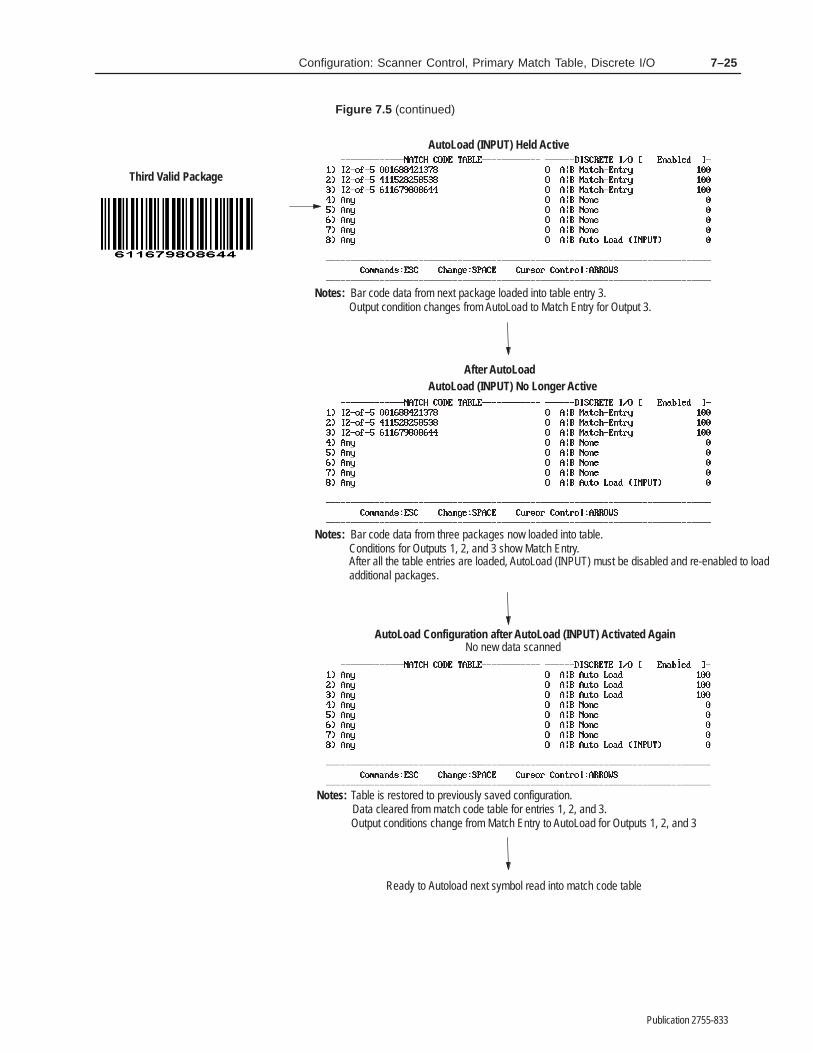
7–25Configuration: Scanner Control, Primary Match Table, Discrete I/O
Publication 2755-833
Figure 7.5 (continued)
Third Valid Package
After AutoLoad
AutoLoad (INPUT) Held Active
Notes:Output condition changes from AutoLoad to Match Entry for Output 3.Bar code data from next package loaded into table entry 3.
AutoLoad (INPUT) No Longer Active
Notes: Bar code data from three packages now loaded into table.Conditions for Outputs 1, 2, and 3 show Match Entry.
AutoLoad Configuration after AutoLoad (INPUT) Activated Again
Notes: Table is restored to previously saved configuration.Data cleared from match code table for entries 1, 2, and 3.
No new data scanned
Output conditions change from Match Entry to AutoLoad for Outputs 1, 2, and 3
additional packages.After all the table entries are loaded, AutoLoad (INPUT) must be disabled and re-enabled to load
Ready to Autoload next symbol read into match code table

������ �
Publication 2755-833
����� �������� ���������������� �� ��������
You can use the screen illustrated below to set up match code entriesin the Extended Match Code Table. You can define up to 128 entrieshere that provide added flexibility in response to incoming data overthe Primary Match Codes described in the previous chapter.
Using Extended Match Codes you can compare all incoming dataagainst table entries that you create to meet your own unique needs.The decoder can then count valid matches, and optionally fire one ormore outputs.
Extended Match Codes provide a way to gather extremely detailedinformation based on decoder activity, and to exercise an additionallevel of control over decoder output activities.
The Extended Match Codes differ from the Primary Match Codes ina number of ways:
• Extended Match Code counters appear on the same screen fromwhich they are controlled (the primary counters appear on aseparate Status and Primary Counters screen)
• Extended Match Codes can activate multiple outputs, the durationof which are defined in the Primary Match Code Table (PrimaryMatch Codes can each fire only a single output).
This screen displays the extended match code table in eight sets ofsixteen entries. Set one includes entries 1 through 16, set 2 includes17 through 32, and so on. The entry numbers (1 through 128) appearon the left side of the screen.
Extended Match Table

8–2 Configuration: Extended Match Table and Counters
Publication 2755-833
Each parameter is defined below. The options for each parameter aresummarized in a table, and explained more fully in the text. Thedefault setting for each parameter is displayed in bold letters in thetable.
Screen Status
Field Type Options
Select
Auto RefreshReset All CountsReset Set OnlyNext SetPrevious Set
This parameter can be used to control three different functionsrelating to the extended match codes:
• It determines whether the display is refreshed regularly
Selecting the default Auto Refresh setting will result in alldisplayed counters being updated every second.
• It permits resetting the value of extended match code tablecounters to zero
Selecting Reset All Counts zeroes all extended counters, whetherthey are among the currently displayed set or not. Selecting ResetSet Only zeroes only those counters in the currently displayed set.The system will ask you to confirm either reset command beforeit takes any action.
• It provides a means to move through all eight sets as necessary
Selecting Next Set displays the next set of sixteen extended matchcode entries. Selecting Previous Set displays the previous set ofsixteen extended match code entries.
Both commands treat all eight sets as a closed loop. If you selectNext Set while displaying set 8, the system will display set 1. Ifyou select Previous Set while displaying set 1, the system willdisplay set 8.
Once you’ve selected either Next Set or Previous Set, you cancontinue to scroll through all sets by repeatedly pressing [Return].Note, however, that there may be a slight delay while the systemprepares and formats each new set for display. If you hold downthe [Return] key in an effort to speed up paging, you are likely topass your intended destination.
It is not necessary to assign extended match code values in sequence.One could, for example, assign match patterns to entries 1, 2, 5, 7,12, and 16 in set 1, nothing in set 2, and 33 through 35 in set 3. Thedetails of each application will determine the strategy used inassigning (or not assigning) extended match code patterns.

8–3Configuration: Extended Match Table and Counters
Publication 2755-833
Status of Counter Set
Field Type Options
Select EnabledDisabled
This parameter activates or deactivates the counters within theparticular set of extended match code values currently displayed. Thedefault value is Enabled, which means that any extended match codetable entry in the currently displayed set to which a match pattern hasbeen assigned will be enabled. Selecting Disabled turns off allentries in the currently displayed set. Keep in mind that thisparameter affects only the currently displayed set.
Use the Screen Status parameter described above to move amongsets within the table. Note that when moving from one screen toanother the “Set” identifier changes to reflect the number of the setcurrently displayed.
The ability to turn individual sets of extended match code tableentries on and off at will provides a potentially useful additionallevel of process control and flexibility.
Mode
Field Type Options
Select
A = AutoloadM = Match EntryD = DisabledL = Lot
The Mode parameter controls the operational status of individualentries in the extended match code table. The default setting isDisabled. Other choices include:
• Autoload, which configures the specified extended match codetable entry to match the bar code data from the first validpackage(s) into the extended match code table
Once a pattern is entered, the Mode parameter changes to MatchEntry.
If the bar code data contains the ”%” character, the decoderdisplays %% in the match code table, but records a single % inthe data. Use the ”%” character to enter any non-printablecharacter. For example, %M represents CTRL-M, or carriagereturn. See Appendix I.
• Match Entry, which activates the specified output when bar codedata matches the string in that row➀
➀ The duration of Extended Match Code Table outputs are established in the Primary Match Code Tablebelow.

8–4 Configuration: Extended Match Table and Counters
Publication 2755-833
Used for verification of specific label information. Thecorresponding output counter increments each time a match entryoccurs.
• Lot, which is an advanced capability available only in theextended match code table, and not in the primary match codetable
When Lot is selected, the decoder will change the Modeparameter to Match Entry, M, place into the extended match codetable entry the value of the first Interleaved 2-of-5 label it reads,and increment the counter. If Any had been selected as theSymbology, it will change to I 2-of-5. Every time the systemencounters a matching I 2-of-5 label it will then:
– Increment the counter– Activate appropriate outputs.➀
This will continue until the decoder encounters a Code 39 labelwith the same value, at which point the system will:
– Reset the Mode to Disable– Change the Symbology to Code 39– Increment the counter a final time– Activate appropriate outputs a final time.➀
You can use multiple Lot entries, and have them runningindependently of one another. The Lot parameter provides a levelof process monitoring and control sophistication required in onlya few applications, but highly valuable where needed to generatestatistical information.
For example, suppose extended match code table entry 1 is set upfor lot mode, with activation of output 4. If the first Interleaved2-of-5 symbol read by the decoder has a value of 123456, thenthe mode becomes Match Entry, and 123456 becomes the matchstring.
Subsequent I 2 of 5 symbols with the same value will eachincrement the counter in row 1, and activate output 4. The firstCode 39 symbol read that has the value 123456 will “close” thelot, and change the Symbology value from I 2 of 5 to Code 39,change M to D for the Mode, activate output 4 for the last time,and increment the counter a final time. This “closed” lot will notincrement the counter or activate outputs for any I 2 of 5 or Code39 symbols once the lot is closed. Instead, it will open a new lot ifone is available.
8–5Configuration: Extended Match Table and Counters
Publication 2755-833
Source
Field Type Options
Select
A (Default for DS)BA|B = A or B (Default for DD)A–B = Precedent determined
Specifies from which scanner(s) an event can originate and meet theextended match pattern requirements. For single head decoders,Scanner A is the default value. For dual head decoders, the defaultvalue is A|B, which means that the decoder will accept input fromeither A or B to create a match. Other options include Scanner B, orprecedent determined (A–B).
When set to A–B, the decoder will use the first input from eitherScanner A or Scanner B to establish a precedent for all followinginputs. If, for example, the first input comes via Scanner B, then onlydata from Scanner B will be matched from that point on.
Symbology
Field Type Options
Select
Code 39Interleaved 2-of-5CodabarUPC-AUPC-EEAN-8EAN-13Code 128Pharma–Code①Any
① Applies only to decoders equipped with the optionalPharma–Code capabilities.
Selects the symbology of the match code string. You can select anyone of the symbologies for each extended match code string.
Note: Any is the default value in the Symbology field for all entriesin the match code tables.
8–6 Configuration: Extended Match Table and Counters
Publication 2755-833
Match Pattern String
Field Type Options
Edit Text 0 to 32 charactersBlank
Defines the characters for a specified match code string (1 - 128).The default is no characters (Blank), which means a match codestring is not defined.
You can enter up to 32 characters for each match code string(including non-printable control characters). Enter the characters asthey will be transmitted to the host. Do not include check digits ifyou disabled the Include Check Character parameter for theselected symbology.
The string accepts the question mark (?) as a single character wildcard. A position containing a ? will match any single ASCIIcharacter in the same position of the decoded data.
Note: The Extended Match Code tables interpret a question markdifferently than do the Host Replacement rules. The question markfunctions as a generic wildcard when used in the Extended MatchCode Table, and as a metacharacter in the Host MessageReplacement Rules.
The decoder compares all decoded data with the specified entries inthe match code table. If the decoded data matches any of the 128strings, a match condition occurs.
Count
Field Type Options
Edit Numeric 0 through 9999990
This field displays the current value of the extended match count foreach table entry. The count automatically increments when thepattern, source, and symbology values all match a given extendedmatch pattern. You can edit this field to set a specific start valuewhen desired.

8–7Configuration: Extended Match Table and Counters
Publication 2755-833
Loading
Field Type Options
Edit Numeric 0 through 9, X0
In the most general sense, loading provides a means to distribute theresponse to incoming data among the eight discrete outputs. Loadinginstructs the decoder to respond to a match by activating the discretecorresponding to the next column number in which a nonzero valueappears.
The default value of 0 disables loading for a given discrete. Valuesinclude 0 through 9, and X.
Activation occurs from left to right in a “round-robin” fashion.During operation, a “greater than” symbol (>) will appear on theterminal screen to indicate the next discrete scheduled to fire. Anyoutput set to “X” will fire every time a match is successful, inaddition to the appropriate “round-robin” output.
Note: The duration of Extended Match Code Table outputs areestablished in the Primary Match Code Table. See below.
Given a situation where discretes 5, 6, and 8 are activated withloading values of 1, 3, and 1, the table below shows what wouldhappen during three complete cycles (15 total matches). In theexample below, a bold horizontal line marks the beginning of eachnew cycle.

8–8 Configuration: Extended Match Table and Counters
Publication 2755-833
MatchInternal Status of Counters On Terminal Display➀
Match #1 2 3 4 5 6 7 8 1 2 3 4 5 6 7 8
0 0 0 0 0 1 3 0 1 • • • • >1 3 • 1
1 0 0 0 0 0 3 0 1 • • • • 1 >3 • 1
2 0 0 0 0 0 2 0 1 • • • • 1 3 • >1
3 0 0 0 0 0 2 0 0 • • • • 1 >3 • 1
4 0 0 0 0 0 1 0 0 • • • • 1 >3 • 1
5 0 0 0 0 1 3 0 1 • • • • >1 3 • 1
6 0 0 0 0 0 3 0 1 • • • • 1 >3 • 1
7 0 0 0 0 0 2 0 1 • • • • 1 3 • >1
8 0 0 0 0 0 2 0 0 • • • • 1 >3 • 1
9 0 0 0 0 0 1 0 0 • • • • 1 >3 • 1
10 0 0 0 0 1 3 0 1 • • • • >1 3 • 1
11 0 0 0 0 0 3 0 1 • • • • 1 >3 • 1
12 0 0 0 0 0 2 0 1 • • • • 1 3 • >1
13 0 0 0 0 0 2 0 0 • • • • 1 >3 • 1
14 0 0 0 0 0 1 0 0 • • • • 1 >3 • 1
➀ Tinted cells in this table show location of indicator arrow (“greater than” symbol). Cells are nothighlighted on screen.
Note that the numbers displayed on the terminal during processingdo not change as loading progresses. Only the “greater than” symbolchanges, moving as necessary to indicate the next scheduled discreteactivation.
Note also that the value in each vertical (output) column hasmeaning only in relation to the other values on the same horizontal(match entry) row. To find the percentage of cases in which a givenloading value will fire, simply divide that value by the sum thevalues for that match, then multiply by 100.
0 + 0 + 0 + 0 + 1 + 3 + 0 + 1 = 5
In the example above, discretes 5 and 8 will each fire 20% of thetime (1/5*100), while discrete 6 will fire 60% of the time (3/5*100).

8–9Configuration: Extended Match Table and Counters
Publication 2755-833
Output Duration
!ATTENTION: Outputs that are addressed frommultiple Extended Match Code Table entries (or fromboth Primary and Extended Match Code Table entries)and have overlapping durations will activate as shownbelow. Failure to consider this fact could lead tounexpected discrete output behavior.
The settings in the Primary Match Code Table determine the durationof all outputs initiated by the Extended Match Codes.
For example, assume output 1 is set to activate for 100 ms on amatch to 1234 in the Primary Match Code Table, and to activate on amatch to 1345 in the Extended Match Code Table. The duration ofthe Extended Match Code Table activation will be 100 ms (asestablished in the Primary Match Code Table). If the decoder reads1234, followed 75 ms later by 1345, the resulting timing will be the175 ms. The following illustration will help explain why.
Read 1234Output Timing of
1234 Alone
Output Timing of1345 AloneRead 1345
Output Timing of12341345
Milliseconds0 25 50 75 100 125 150 175 200
CombinedResult
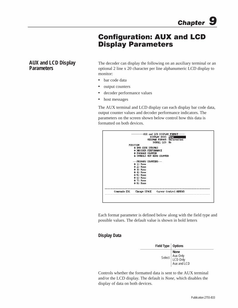
������ �
Publication 2755-833
��� ��������� �� �� ��������� ��������
The decoder can display the following on an auxiliary terminal or anoptional 2 line x 20 character per line alphanumeric LCD display tomonitor:
• bar code data
• output counters
• decoder performance values
• host messages
The AUX terminal and LCD display can each display bar code data,output counter values and decoder performance indicators. Theparameters on the screen shown below control how this data isformatted on both devices.
Each format parameter is defined below along with the field type andpossible values. The default value is shown in bold letters
Display Data
Field Type Options
Select
NoneAux OnlyLCD OnlyAux and LCD
Controls whether the formatted data is sent to the AUX terminaland/or the LCD display. The default is None, which disables thedisplay of data on both devices.
AUX and LCD DisplayParameters

9–2 Configuration: AUX and LCD Display Parameters
Publication 2755-833
Select AUX Only to display the data on the AUX terminal but not theLCD display. Select LCD Only to display the data on the LCDdisplay but not the AUX terminal. Select AUX and LCD to enablethe display of data on both devices.
The display parameters set for the AUX port apply to the AUXterminal when it is in manual data entry mode (See Chapter 13 forinformation on manual data entry).
Message Format
Field Type Options
Select UnformattedHost Format
Controls the format of the bar code data that is displayed. Thedefault is Unformatted, which means the bar code data is displayedunformatted.
Select Host Format to display scanned data in the host messageformat set by the parameters on the Host Message Formatconfiguration screen.
Note: Manually entered data cannot be sent to the LCD.
For example, assume the scanned bar code data is 123456. If the datais displayed unformatted, it is sent as 123456. If the data is displayedin the host format (using predefined configuration parameters), it issent as:
Start Character
Field DelimiterCode 39
End Message Character
#LD8–AScanner A Data / 01123456 / / 000013CRLF
Package Count
Bar Code Label Data
Header Mes-sage
Field Delimiters
Source Identifier
See the Host Message Format screen configuration instructions inChapter 11 for details on the configuration parameters that controlthe host message format.
Note: The Aux Terminal internal selector (described in Chapter 13)must be installed in the data entry position to send host formatteddata to the Aux Port.
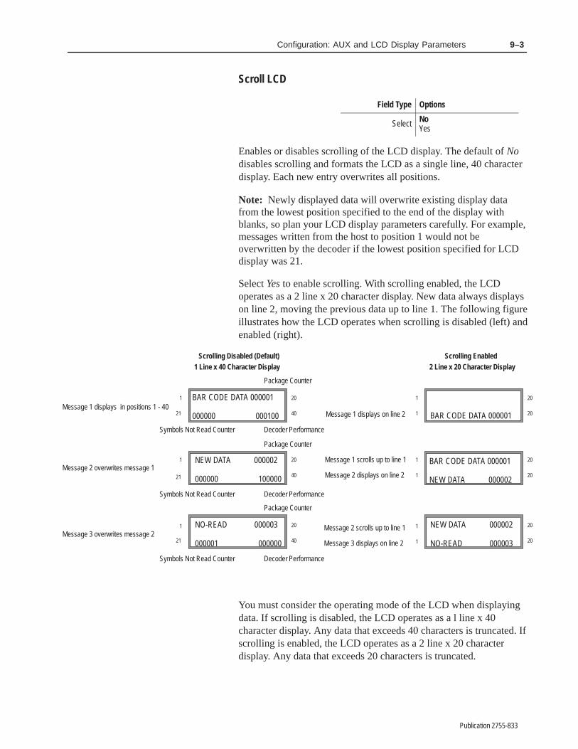
9–3Configuration: AUX and LCD Display Parameters
Publication 2755-833
Scroll LCD
Field Type Options
Select NoYes
Enables or disables scrolling of the LCD display. The default of Nodisables scrolling and formats the LCD as a single line, 40 characterdisplay. Each new entry overwrites all positions.
Note: Newly displayed data will overwrite existing display datafrom the lowest position specified to the end of the display withblanks, so plan your LCD display parameters carefully. For example,messages written from the host to position 1 would not beoverwritten by the decoder if the lowest position specified for LCDdisplay was 21.
Select Yes to enable scrolling. With scrolling enabled, the LCDoperates as a 2 line x 20 character display. New data always displayson line 2, moving the previous data up to line 1. The following figureillustrates how the LCD operates when scrolling is disabled (left) andenabled (right).
Scrolling Disabled (Default)
Message 1 scrolls up to line 1
Message 2 displays on line 2
Message 1 displays on line 2
Message 2 scrolls up to line 1
Message 3 displays on line 2
Scrolling Enabled
BAR CODE DATA 000001
000000 000100Message 1 displays in positions 1 - 40
1
21
20
40
1 20
40
20
40
1
1
1
20
20
1
1
20
20
20
20
1
1
21
21
Message 2 overwrites message 1
Message 3 overwrites message 2
1 Line x 40 Character Display 2 Line x 20 Character Display
NEW DATA 000002
000000 100000
NO-READ 000003
000001 000000
NEW DATA 000002
NO-READ 000003
BAR CODE DATA 000001
NEW DATA 000002
BAR CODE DATA 000001
Symbols Not Read Counter
Symbols Not Read Counter
Symbols Not Read Counter
Decoder Performance
Package Counter
Package Counter
Package Counter
Decoder Performance
Decoder Performance
You must consider the operating mode of the LCD when displayingdata. If scrolling is disabled, the LCD operates as a l line x 40character display. Any data that exceeds 40 characters is truncated. Ifscrolling is enabled, the LCD operates as a 2 line x 20 characterdisplay. Any data that exceeds 20 characters is truncated.

9–4 Configuration: AUX and LCD Display Parameters
Publication 2755-833
Position: Bar Code Strings
Field Type Options
Edit Numeric 0 through 400
Defines the character position at which to start displaying the barcode data. The default of 0 disables the display of bar code data.
To start the bar code data display at a specific position, enter astarting character position between 1 and 40. For example, to startthe display at character position 1, enter 1.➀
Position: Decoder Performance
Field Type Options
Edit Numeric 0 through 400
Defines the character position at which to start displaying thedecoder performance values for Scanner A and (for DD decoders)Scanner B. The performance indicator displays one value for eachscanner. Each is left justified and can be a value up to 100. For DDdecoders, the first value applies to Scanner A; the second valueapplies to Scanner B. The default of 0 disables the display of thisdata.
To determine the starting position for decoder performance display,enter a starting character position between 1 and 40. For example, tostart the display at character position 21, select 21. Assumingscrolling is disabled, the display will appear beginning in the firstposition on the second line of the LCD display.①
Remember when selecting a starting position that you will needspace for up to 3 characters for a single scanner and 6 characters fortwo scanners.
Position: Package Counter
Field Type Options
Edit Numeric 0 through 400
Defines the character position at which to start displaying the 6 digitpackage counter. The default of 0 disables the display of the packagecounter.
➀ The Default Prompt Message and host messages always start in position 1. To prevent other data frooverwriting these messages on the LCD Display, select a position greater than the message length aLCD scrolling.

9–5Configuration: AUX and LCD Display Parameters
Publication 2755-833
To start the package counter display at a specific position, enter astarting character position between 1 and 40. For example, to startthe display at character position 30, select 30.➀
Position: Symbols Not Read Counter
Field Type Options
Edit Numeric 0 through 400
Defines the character position at which to start displaying the 6 digitno-read counter. The default of 0 disables the display of the no-readcounter.
To start the no-read counter display at a specific position, enter astarting character position between 1 and 40. For example, to startthe display at character position 30, select 30.➀
Position: Primary Counters
Field Type Options
Edit Numeric 0 through 400
Defines the character position at which to start displaying the 6 digitprimary output counters (1–8). The default of 0 disables the displayof the specified output counter.
To start the output counter display at a specific position, enter astarting character position between 1 and 40. For example, to startthe display at character position 30, select 30.
Remember, each output counter occupies 6 character positions. Ifyou display more than one counter, allow enough positions for eachcounter to prevent data from overwriting other data.➀
Note: All of the output counters (1-8) are formatted the same way.
Displaying Host Messages
The LCD Display can display text messages that are sent from thehost using the ASCII or PCCC form of the Display Text Messagecommand (depending on the host protocol you are using). Refer toChapters 15 and 16 for additional information on ASCII and PCCCcommands.
➀ The Default Prompt Message and host messages always start in position 1. To prevent other data frooverwriting these messages on the LCD Display, select a position greater than the message length aLCD scrolling.
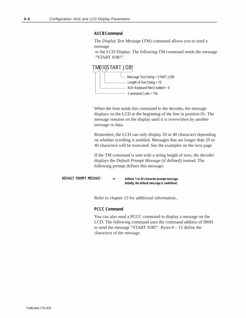
9–6 Configuration: AUX and LCD Display Parameters
Publication 2755-833
ASCII Command
The Display Text Message (TM) command allows you to send amessage to the LCD Display. The following TM command sends the message ”START JOB!”.
TM010START JOB!
Message Text String = START JOB!
Length of Text String = 10
AUX Keyboard Not Enabled = 0
Command Code = TM
When the host sends this command to the decoder, the messagedisplays on the LCD at the beginning of the line in position 01. Themessage remains on the display until it is overwritten by anothermessage or data.
Remember, the LCD can only display 20 or 40 characters dependingon whether scrolling is enabled. Messages that are longer than 20 or40 characters will be truncated. See the examples on the next page.
If the TM command is sent with a string length of zero, the decoderdisplays the Default Prompt Message (if defined) instead. Thefollowing prompt defines this message:
Defines 1 to 20 character prompt message.Initially, the default message is undefined.
Refer to chapter 13 for additional information..
PCCC Command
You can also send a PCCC command to display a message on theLCD. The following command uses the command address of 900Hto send the message ”START JOB!”. Bytes 6 – 15 define thecharacters of the message.
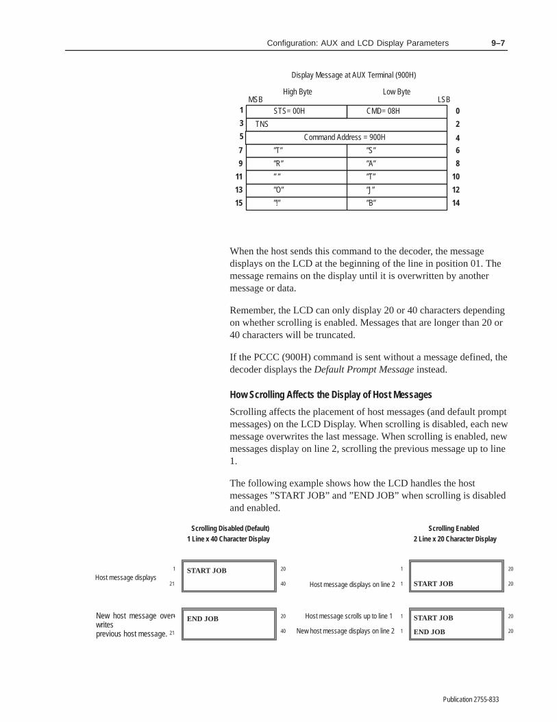
9–7Configuration: AUX and LCD Display Parameters
Publication 2755-833
0
5
STS= 00H
TNS
High Byte Low ByteMSB LSB
1
3 2
8
CMD= 08H
Display Message at AUX Terminal (900H)
Command Address = 900H 4
7 ”T” ”S”
10
9 ”R” ”A”
12
11 ” ” ”T”
14
13 ”O” ”J”
15 ”!” ”B”
6
When the host sends this command to the decoder, the messagedisplays on the LCD at the beginning of the line in position 01. Themessage remains on the display until it is overwritten by anothermessage or data.
Remember, the LCD can only display 20 or 40 characters dependingon whether scrolling is enabled. Messages that are longer than 20 or40 characters will be truncated.
If the PCCC (900H) command is sent without a message defined, thedecoder displays the Default Prompt Message instead.
How Scrolling Affects the Display of Host Messages
Scrolling affects the placement of host messages (and default promptmessages) on the LCD Display. When scrolling is disabled, each newmessage overwrites the last message. When scrolling is enabled, newmessages display on line 2, scrolling the previous message up to line1.
The following example shows how the LCD handles the hostmessages ”START JOB” and ”END JOB” when scrolling is disabledand enabled.
Scrolling Disabled (Default)
Host message scrolls up to line 1
New host message displays on line 2
Host message displays on line 2
Scrolling Enabled
START JOBHost message displays
1
21
20
40
1 20
40
1
1
20
20
1
1
20
2021
New host message over-writesprevious host message.
1 Line x 40 Character Display 2 Line x 20 Character Display
END JOB
START JOB
START JOB
END JOB
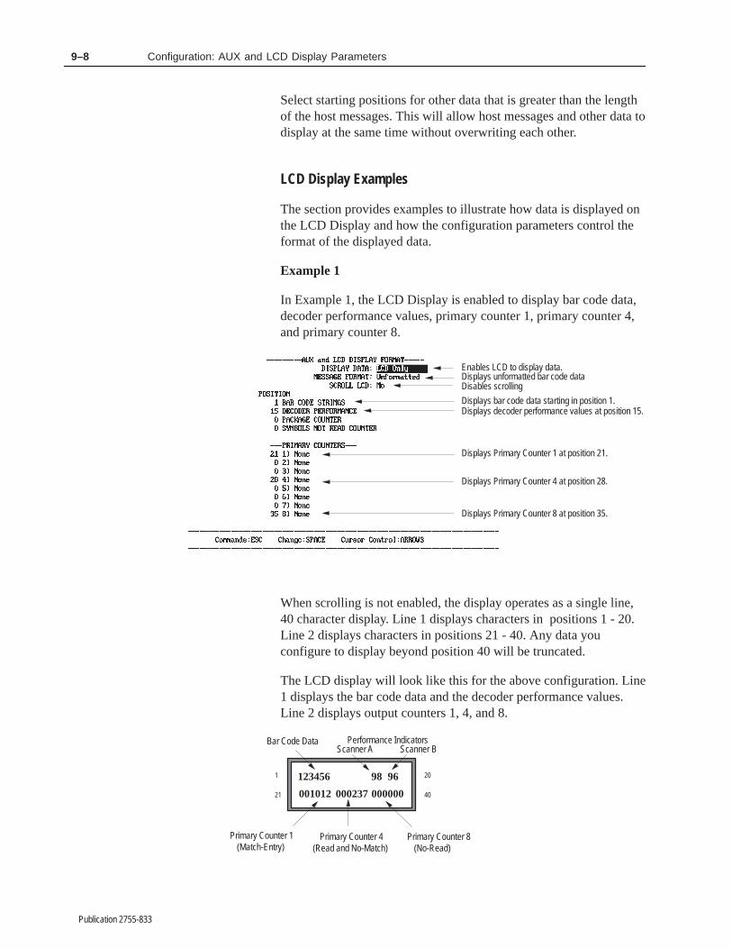
9–8 Configuration: AUX and LCD Display Parameters
Publication 2755-833
Select starting positions for other data that is greater than the lengthof the host messages. This will allow host messages and other data todisplay at the same time without overwriting each other.
LCD Display Examples
The section provides examples to illustrate how data is displayed onthe LCD Display and how the configuration parameters control theformat of the displayed data.
Example 1
In Example 1, the LCD Display is enabled to display bar code data,decoder performance values, primary counter 1, primary counter 4,and primary counter 8.
Enables LCD to display data.Displays unformatted bar code data
Displays bar code data starting in position 1.Displays decoder performance values at position 15.
Displays Primary Counter 4 at position 28.
Displays Primary Counter 8 at position 35.
Disables scrolling
Displays Primary Counter 1 at position 21.
When scrolling is not enabled, the display operates as a single line,40 character display. Line 1 displays characters in positions 1 - 20.Line 2 displays characters in positions 21 - 40. Any data youconfigure to display beyond position 40 will be truncated.
The LCD display will look like this for the above configuration. Line1 displays the bar code data and the decoder performance values.Line 2 displays output counters 1, 4, and 8.
123456 98 96
001012 000237 000000
Bar Code Data Performance Indicators
Primary Counter 1(Match-Entry)
Primary Counter 4(Read and No-Match)
Primary Counter 8(No-Read)
1
21 40
20
Scanner A Scanner B
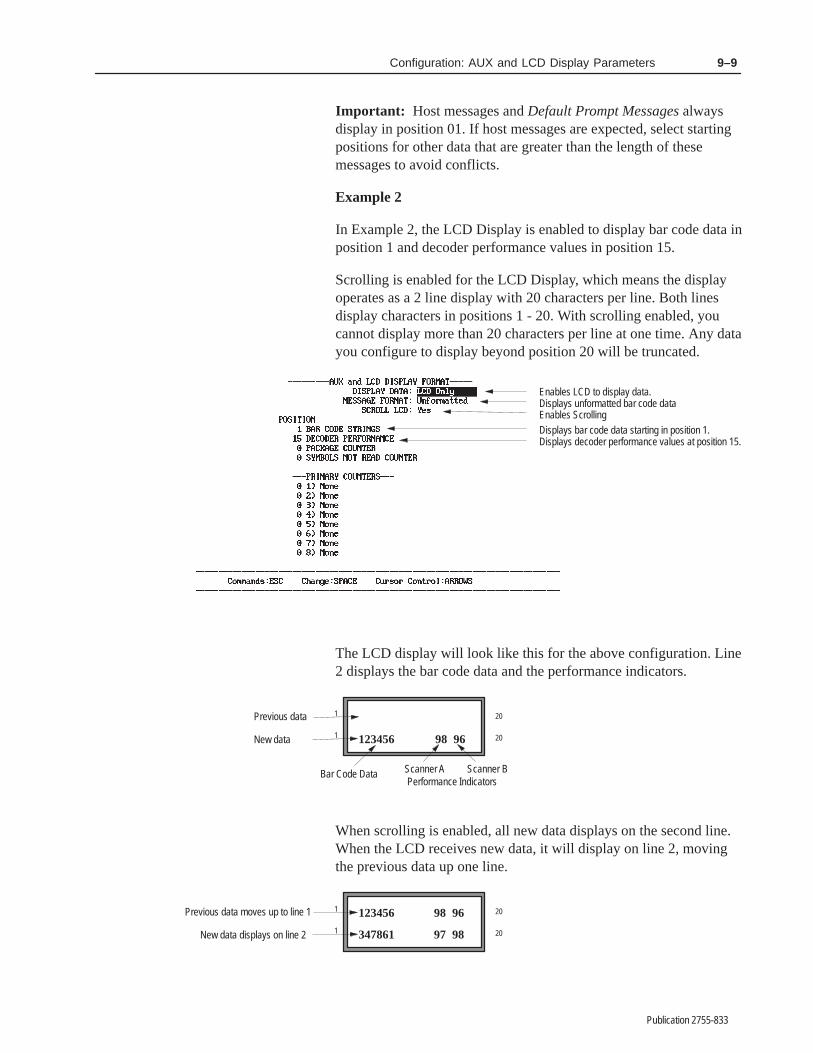
9–9Configuration: AUX and LCD Display Parameters
Publication 2755-833
Important: Host messages and Default Prompt Messages alwaysdisplay in position 01. If host messages are expected, select startingpositions for other data that are greater than the length of thesemessages to avoid conflicts.
Example 2
In Example 2, the LCD Display is enabled to display bar code data inposition 1 and decoder performance values in position 15.
Scrolling is enabled for the LCD Display, which means the displayoperates as a 2 line display with 20 characters per line. Both linesdisplay characters in positions 1 - 20. With scrolling enabled, youcannot display more than 20 characters per line at one time. Any datayou configure to display beyond position 20 will be truncated.
Enables LCD to display data.Displays unformatted bar code data
Displays bar code data starting in position 1.Displays decoder performance values at position 15.
Enables Scrolling
The LCD display will look like this for the above configuration. Line2 displays the bar code data and the performance indicators.
123456 98 96
Bar Code DataPerformance Indicators
1
20
20
Scanner A Scanner B
1
Previous data
New data
When scrolling is enabled, all new data displays on the second line.When the LCD receives new data, it will display on line 2, movingthe previous data up one line.
347861 97 98
1
20
20
1
Previous data moves up to line 1
New data displays on line 2
123456 98 96

9–10 Configuration: AUX and LCD Display Parameters
Publication 2755-833
The main logic board of the decoder has a potentiometer foradjusting the contrast of the LCD Display. Figure 9.1 shows thegeneral location of the potentiometer on the main logic board.
Figure 9.1 Potentiometer for LCD display contrast
Main Logic Board
Enclosure
LCD DISPLAYCONTRAST
ADJUST
Potentiometer for LCD Display Contrast
AUX TERMINAL
DATA CONFIG.ENTRY
Mounting bracket for optional battery
∨∨
To adjust the contrast of the LCD Display:
1. Power on decoder, but if possible disconnect power from moduleconnectors.
2. Loosen the two screws which secure the cover of the decoder andopen.
3. Using your fingers, turn the LCD Display potentiometer to theleft or right until the desired contrast or readability is achieved.
4. Close cover of decoder and tighten screws.
AUX Terminal Display Examples
The section provides examples to illustrate how data is displayed atthe AUX terminal and how the configuration parameters control theformat of the displayed data.
Example 1
In Example 1, the AUX terminal is configured to displayunformatted bar code data in position 21.
Adjusting Contrast ofLCD Display

9–11Configuration: AUX and LCD Display Parameters
Publication 2755-833
Enables AUX Terminal to display data.Displays unformatted bar code data.
Displays bar code data starting at position 21.
The AUX terminal display will look like this for the aboveconfiguration.
Bar Code Data
229176229183229192229206229240229253229263229268229285229322229327229336229345229361229371229391229427229433229438229449229456229466229476229493229517
Example 2
In Example 2, bar code data configured to display in position 21 willnot display because the AUX terminal has not been enabled todisplay data.

9–12 Configuration: AUX and LCD Display Parameters
Publication 2755-833
Disables the display of data on any device
Configures bar code data to display in position 21
Example 3
In Example 3, the AUX terminal is enabled to display bar code data,decoder performance values, and the package counter.
Enables AUX terminal to display data.Displays unformatted bar code data.
Displays bar code data starting at position 21.Displays Decoder Performance values at position 50.Displays Package Counter at position 60.
The terminal display will look like this for the above configuration.

9–13Configuration: AUX and LCD Display Parameters
Publication 2755-833
Bar Code DataPackage Counter
Decoder Performance ValuesScanner A Scanner B
229176229183229192229206229240229253229263229268229285229322229327229336229345229361229371229391229427229433229438229449229456229466229476229493229517
0 98
98 00 96
0 9596 099 00 97
97 00 99
0 9699 099 00 95
97 00 98
0 9998 097 098 00 9596 099 00 97
97 00 99
229176 001724001725001726001727001728001729001730001731001732001733001734001735001736001737001738001739001740001741001742001743001744001745001746001747001748

����� ��
Publication 2755-833
������������� ���� ������� ����� �� �
Function 5 on the Select Operation menu accesses the HostMessage Replacement Rules configuration screen. Use thisfunction to modify the message sent to the host.
Host message replacement rules may not be required in everyapplication. They are unnecessary when your needs include simpleobject counting, or collection of raw bar code data. However, hostmessage replacement rules will prove useful when you need tosubstitute a predetermined output message for specific bar code dataduring decoding. With them you can:
• send data in a particular, predefined order regardless of the orderin which the labels were read
• mask bar code characters to simplify operations and speedprocessing
• truncate or pad the length of the data package
• substitute a predetermined text string for one or more expectedvalues.
• convert abstract bar code contents into more easily understoodtext form
• categorize labels based upon selected portions of their contents.
Both the search and replacement strings that make up a HostMessage Replacement Rule can consist of a combination of standardASCII characters and special characters known as metacharacters.Metacharacters are explained later in this section.
Introduction toHost MessageReplacement Rules

10–2 Configuration: Host Message Replacement Rules
Publication 2755-833
Symbols vs. Host Message Fields
Understanding host message replacement rules and their use requiresthat you clearly understand the difference between two frequentlyconfused terms.
A bar code symbol is the set of bars and spaces from which thescanner gathers data for interpretation by the decoder.
A message field is the decoded information sent from the decoder toa host after processing an incoming symbol.
In the most simple terms, a symbol can be thought of as a stimulus tothe decoder, and a message field (or group of message fieldsassembled into a host message) can be considered the response tothat stimulus.
Introduction to Host Message Replacement Rules
The decoder allows you to use up to 16 Host Message ReplacementRules. Each rule can be enabled and defined as necessary to meetyour own application needs.
In addition to the prompt line at the bottom of the screen, the HostMessage Replacement Rules configuration screen is made up ofthree sections:

10–3Configuration: Host Message Replacement Rules
Publication 2755-833
• Rule status, located on the far left side of the screen
Each number represents an available host message replacementrule. Currently enabled rules are marked with an asterisk (*).Rules are enabled by assigning a value to the Find StringContaining field.
• Host message replacement rule definition, located in the upperhalf of the screen
This section displays the current search rule criteria (whichinclude Source, Symbology, Symbol Number, and Find StringContaining) and the replacement string to send to the host whenmatches are found. The rule definition also includes parameters tofix the length of the field, the character used to “fill” the field,and the alignment of the string within the field.
• Example testing, in the lower portion of the screen
This section provides a “worksheet” where you can insert samplebar code strings to test the performance of your rules. This featureallows you to conveniently “debug” your replacement ruleexpressions for structural and logical errors before going on-line.You simply input the test bar code string on the left. The stringthat will appear in the host message after application of thedisplayed rule appears on the right. If your test string does notcreate a match, you will be notified of that fact on the right sideof the screen.
Taken together, these three sections provide for full control overhost message replacement rules, and enable you to format complete,comprehensible message fields as required.
Each format parameter is defined below along with the field type andpossible values. The default value is shown in bold letters in theparameter tables. A careful study of the examples that follow theparameter descriptions will help explain their use.
Metacharacters
The decoder provides a complete set of special purpose charactersyou can use to perform logical functions on characters, expressions,or even entire strings. These characters are known as metacharacters.Simply put, they are string manipulation commands consisting ofstandard ASCII characters which you can embed within search orreplacement strings. Each metacharacter conveys a specificinstruction to the decoder software, and acts upon a clearly definedrange within the string. Metacharacters can be used with standardalphanumeric characters to describe and manipulate even the mostcomplex substitution scenarios with ease.
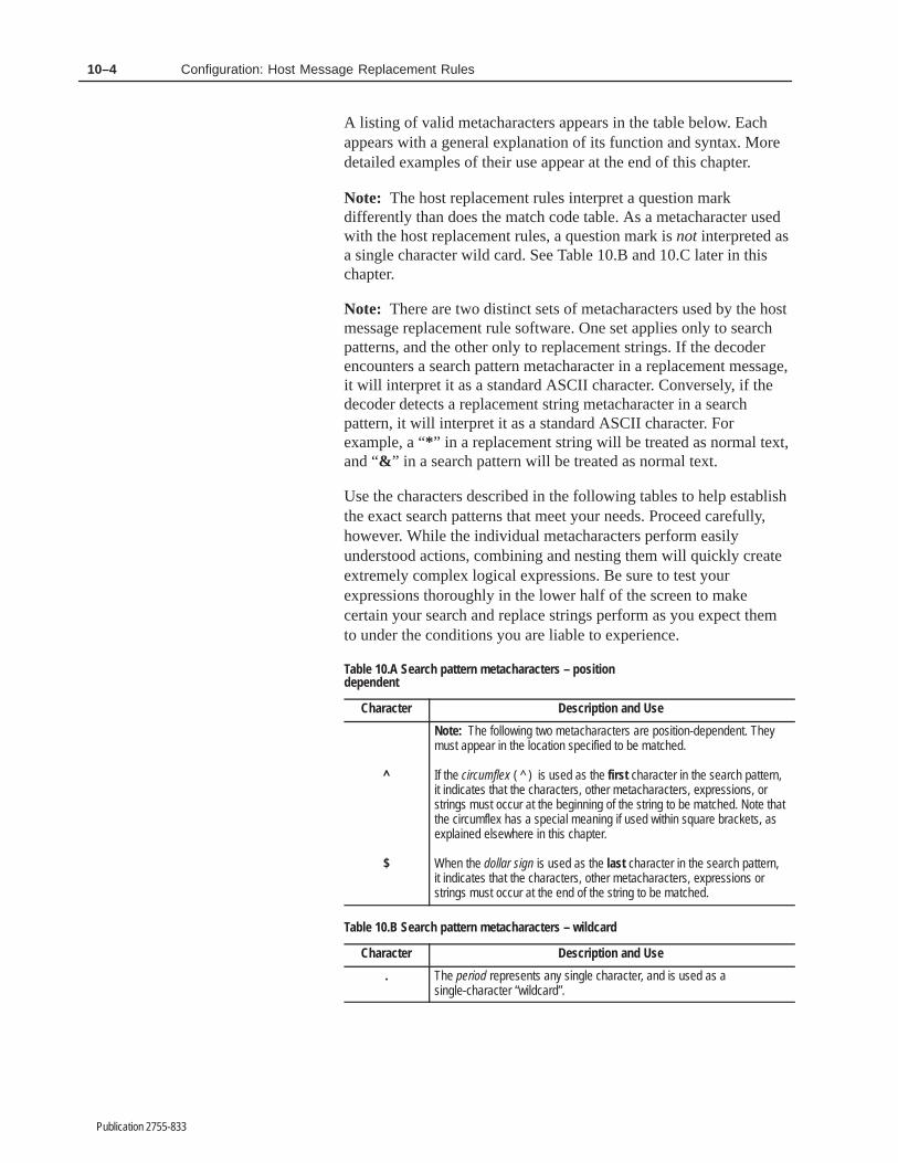
10–4 Configuration: Host Message Replacement Rules
Publication 2755-833
A listing of valid metacharacters appears in the table below. Eachappears with a general explanation of its function and syntax. Moredetailed examples of their use appear at the end of this chapter.
Note: The host replacement rules interpret a question markdifferently than does the match code table. As a metacharacter usedwith the host replacement rules, a question mark is not interpreted asa single character wild card. See Table 10.B and 10.C later in thischapter.
Note: There are two distinct sets of metacharacters used by the hostmessage replacement rule software. One set applies only to searchpatterns, and the other only to replacement strings. If the decoderencounters a search pattern metacharacter in a replacement message,it will interpret it as a standard ASCII character. Conversely, if thedecoder detects a replacement string metacharacter in a searchpattern, it will interpret it as a standard ASCII character. Forexample, a “* ” in a replacement string will be treated as normal text,and “& ” in a search pattern will be treated as normal text.
Use the characters described in the following tables to help establishthe exact search patterns that meet your needs. Proceed carefully,however. While the individual metacharacters perform easilyunderstood actions, combining and nesting them will quickly createextremely complex logical expressions. Be sure to test yourexpressions thoroughly in the lower half of the screen to makecertain your search and replace strings perform as you expect themto under the conditions you are liable to experience.
Table 10.A Search pattern metacharacters – positiondependent
Character Description and Use
^
$
Note: The following two metacharacters are position-dependent. Theymust appear in the location specified to be matched.
If the circumflex ( ^ ) is used as the first character in the search pattern,it indicates that the characters, other metacharacters, expressions, orstrings must occur at the beginning of the string to be matched. Note thatthe circumflex has a special meaning if used within square brackets, asexplained elsewhere in this chapter.
When the dollar sign is used as the last character in the search pattern,it indicates that the characters, other metacharacters, expressions orstrings must occur at the end of the string to be matched.
Table 10.B Search pattern metacharacters – wildcard
Character Description and Use
. The period represents any single character, and is used as asingle-character “wildcard”.

10–5Configuration: Host Message Replacement Rules
Publication 2755-833
Table 10.C Search pattern metacharacters – stringmanipulation
Character Description and Use
?
+
*
Note: These metacharacters refer to the character, metacharacter,string, or expression that immediately precedes them.
The question mark instructs the rule to match either no occurrence orone occurrence of what precedes it. This metacharacter is used in asearch string where the character may not appear at all, or may appearonce.
The plus sign instructs the rule to match one or more occurrences ofwhat precedes it. This metacharacter is used in a search string where thecharacter will be present, but you are unsure how many times it appears.
The asterisk instructs the rule to match none or more occurrences ofwhat precedes it. This metacharacter is used in a search string in caseswhere the character may not appear, or may appear one or more times.
Table 10.D Search patter metacharacters – logical operatorsand other special functions
Character Description and Use
[ ] Square brackets ( [ ] ) instructs the rule to match an incoming string if anycharacter enclosed within the brackets appears in the string. A range ofvalues can be represented within the brackets by separating the first andlast characters in the range by a hyphen. Square brackets must be usedin pairs.
Note: The circumflex ( ^ ) can be used as the first character within thesquare brackets to reverse the sense of the expression.
Examples
[ABC] Matches “A”, “B”, or “C”
[L–P] Matches “L”, “M”, “N”, “O”, or “P”
[0 – 9] Matches “0”, “1”, “2”, “3”, “4”, “5”, “6”, “7”, “8”, or “9”
[^A – Z] Matches any character that is not upper casealphabetic
( ) Parentheses can be used in two different ways. They can be used insearch patterns to group characters and metacharacters to formexpressions. Parentheses must be used in pairs.
Examples
(AB)+ The plus sign applies to the expression (AB).Strings that would match this expression include: “AB”, “ABAB”, “123AB”,
and “AB123”.
Parentheses can also be used to identify strings for use in the ReplaceEntire String With field. If a character, string, or expression is surroundedby parentheses in a search pattern, then it can be later recalled in areplace pattern with the “\n” metacharacter described elsewhere in thischapter.
Note: Parentheses may be nested to form complex expressions.

10–6 Configuration: Host Message Replacement Rules
Publication 2755-833
Character Description and Use
| A vertical bar (the shifted “\” character on the keyboard) instructs the ruleto match an incoming string if the character or expression on the left orright of the vertical bar appears in the string.
Examples
A | B Matches “A” or “B”
abc|123 Matches “abc” or “123”
\ The backslash indicates that the following character, which wouldnormally be interpreted as a metacharacter, should instead beinterpreted as a literal ASCII character.
Note: The backslash is used differently in the Replace Patterns. SeeTable 10.E.
Example
\. The period ( . ) will be interpreted as a periodrather than a
single character wildcard.

10–7Configuration: Host Message Replacement Rules
Publication 2755-833
Table 10.E Replacement string metacharacters
Character Description and Use
\n The backslash plus a number 1 through 9 recalls a previously savedstring. Any character, string or expression that is surrounded byparentheses in the search pattern (as described earlier) can be recalledby the replace pattern using the “\n” format. Since the parentheses maybe nested, the number “n” represents the order of the groupings asdefined by the order of the left parenthesis in the search pattern.
Examples
Search Pattern = 123(ABC)Replace Entire String With = \1Incoming String = 123ABC456Result for Host Message = ABC
The search pattern above matches the incoming string. The ReplaceEntire String With value states that the string identified within the firstparentheses should be sent to the host.
Search Pattern = (123(ABC))Replace Entire String With = \1\2Incoming String = 123ABC456Result for Host Message = 123ABCABC
The search pattern above matches the incoming string. The ReplaceEntire String With value states that the string identified within the firstparentheses (123ABC), plus the string identified by the secondparentheses(ABC) should be sent to the host.
& When the ampersand ( & ) is used in a replacement pattern, it indicatesthat the part of the string that matches the search pattern should be sentto the host. Therefore, if the string read contains more characters thanthe search pattern, then the additional characters are discarded.
Examples
Search Pattern = 123ABCReplace Entire String With = &Incoming String = 123ABCResult for Host Message = 123ABC
The search pattern matches the incoming string. The Replace EntireString With value states that the string identified in the search patternshould be sent to the host.
Search Pattern = 123ABCReplace Entire String With = &Incoming String = 123ABC456Result for Host Message = 123ABC
The search pattern matches the incoming string. The Replace EntireString With value states that the string identified in the search patternshould be sent to the host. This does not include the digits 456.
Processing Order
Matches are determined for each of the Host Message Fields (1through 16) by applying the rule parameters as follows:

10–8 Configuration: Host Message Replacement Rules
Publication 2755-833
The lowest numbered rule with the Host Message Field Numbervalue of 1 (or All) will be applied first. If that rule is successful, noother rule specifying field 1 (or All) will be applied. This willcontinue until a rule satisfies the field, or until all appropriate ruleshave been applied to field 1. The decoder will continue this processfor all fields until each is satisfied, or until all appropriate rules havefailed. No-read Replacement strings (if defined) will be substitutedfor the data if the rules fail. See Chapter 11.
Important: You will want to set up your host message replacementrule table with care. Here are a few general guidelines:
• Prioritize your replacement rules. Only one rule can fill a field,and once one rule has filled a field, then no other rules will applyto that field. Define the rule which will lead to the mostpreferable result first, the next preferable result next, and so on.
• If you need to fill specific fields, define the rules for those fieldsfirst.
• When using metacharacters, define first those expressions whichare most restrictive (most specific), and then proceed to thosewhich are less so.
• Define rules specifying All as the host message field number last.This is especially important, because if such a rule creates amatch, then no other rules that occur after it and are directed tospecific host fields can have any affect. (Remember: once onerule has filled a field, then no other rules will apply to that field.)
Source
Field Type Options
Select
A (Default for DS Only)BA|B = A or B (Default for DD only)Aux
Specifies where an event can originate and meet the host messagereplacement rule requirements. For DS decoders, Scanner A is thedefault value. For DD decoders, the default value is A|B, whichmeans that the decoder will accept input from either A or B to createa match. You can also select AUX or, if you have a DD decoder,Scanner B as the source.
The decoder processes rules for the AUX and each of the scannersseparately. For example, if all enabled rules specify Scanner A as thesource, then data received from Scanner B or the auxiliary terminaldoes not pass through the rules and will not be affected by them.
Configuration Parameters
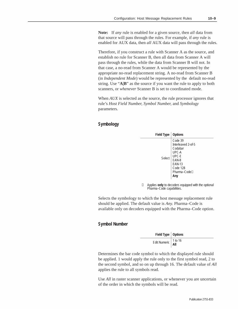
10–9Configuration: Host Message Replacement Rules
Publication 2755-833
Note: If any rule is enabled for a given source, then all data fromthat source will pass through the rules. For example, if any rule isenabled for AUX data, then all AUX data will pass through the rules.
Therefore, if you construct a rule with Scanner A as the source, andestablish no rule for Scanner B, then all data from Scanner A willpass through the rules, while the data from Scanner B will not. Inthat case, a no-read from Scanner A would be represented by theappropriate no-read replacement string. A no-read from Scanner B(in Independent Mode) would be represented by the default no-readstring. Use “A|B” as the source if you want the rule to apply to bothscanners, or whenever Scanner B is set to coordinated mode.
When AUX is selected as the source, the rule processor ignores thatrule’s Host Field Number, Symbol Number, and Symbologyparameters.
Symbology
Field Type Options
Select
Code 39Interleaved 2-of-5CodabarUPC-AUPC-EEAN-8EAN-13Code 128Pharma–Code①Any
① Applies only to decoders equipped with the optionalPharma–Code capabilities.
Selects the symbology to which the host message replacement ruleshould be applied. The default value is Any. Pharma–Code isavailable only on decoders equipped with the Pharma–Code option.
Symbol Number
Field Type Options
Edit Numeric 1 to 16All
Determines the bar code symbol to which the displayed rule shouldbe applied. 1 would apply the rule only to the first symbol read, 2 tothe second symbol, and so on up through 16. The default value of Allapplies the rule to all symbols read.
Use All in raster scanner applications, or whenever you are uncertainof the order in which the symbols will be read.

10–10 Configuration: Host Message Replacement Rules
Publication 2755-833
Note: Using a combination of All in the symbol number field andAll in the host message field number field within a rule creates aspecial situation in which the decoder will attempt to match the ruleusing only those symbols that have not previously satisfied a rule.
A rule in which the host message field number is set to All will try toprocess every symbol to satisfy the search criteria until all of the hostfields are satisfied.
Important: Do not set the host message field number to All unless:
• The Number of Fields in Message parameter is set to 1 on theHost Message Format screen.
OR
• The Number of Fields in Message parameter is set to All on theHost Message Format screen and the Symbols per Packageparameter is set to 1 on the Scanner Control screen
OR
• The Symbol Number parameter is set to All.
Other configurations will result in multiple copies of the same databeing set as different fields in the host message.
For example, if the Number of Fields in Message parameter is set toa number greater than 1, with the host message field number set toAll, then the same symbol will be processed through a single rulemultiple times. For the purposes of this example, assume the numberof fields in message value is set to 3, and the user has enabled rulenumber 1 as shown below.

10–11Configuration: Host Message Replacement Rules
Publication 2755-833
If Scanner A reads the following symbols:
AB1 1AB BA1
Then the host message would be AB1AB1AB1. Since the firstsymbol read satisfies the search criteria, it will continue passingthrough the rule until all host fields are filled.
Changing the symbol number to 2 would lead to a host message of1AB1AB1AB.
Instead, if the Symbol Number parameter is set to All and the hostmessage field number is set to All, then each symbol that hassatisfied a rule is “marked”. That symbol’s marked status prohibitsother rules with both Symbol Number and Host Message FieldNumber parameters set to All from using it.
For example, resetting the symbol number to All in the configurationillustrated above results in a host message of AB11ABBA1.
This occurs because AB1 (the first symbol read) satisfies the rule andis used for host field one. Since AB1 has now been used, and bothsymbol number and host message field number are set to All, AB1won’t be considered for the second pass through the rule. Instead,1AB will satisfy the rule on the second pass, and will be used forhost field two and will be marked so it will not be considered for thethird pass. BA1 satisfies the third pass, and will be used for host fieldthree.
Find String Containing
Field Type Options
Edit TextAny valid string up to 24characters in lengthBlank
If not blank, enables the selected rule number and specifies a stringfor which to search among incoming symbols. The string mayconsist of any valid combination of ASCII characters andmetacharacters. All the Find String Containing fields are empty bydefault, which disables all host message replacement rules. Onlyenabled rules will affect decoder performance. All rules are empty –and therefore disabled – at default startup.

10–12 Configuration: Host Message Replacement Rules
Publication 2755-833
Replace Entire String With
Field Type Options
Edit TextAny valid string up to 24characters in lengthBlank
Defines the string or expression that should be sent to the host toreplace the string that was matched by the search pattern currently ineffect. Whenever the search pattern is satisfied, the replacementpattern defined here will be substituted for the entire string.
Even if the search pattern is only a portion of the incoming string,the entire incoming string is replaced by the replacement pattern. Foran example of how to replace only a portion of the incoming string,see Example 9 at the end of this chapter.
The resulting string appears in the field defined by the host messagefield number. The string or expression may consist of any validcombination of ASCII characters and metacharacters. The defaultvalue is Blank.
Minimum Field Length
Field Type Options
Edit Numeric 0 through 640
Specifies the minimum number of characters in any field thatsatisfies the rule. Fields that are longer than the minimum fieldlength remain unchanged, but fields that are shorter than theminimum length are padded to meet the minimum value. Fillcharacters appear either before or after the existing field, dependingon the field’s alignment.
The default value is 0, which means minimum field length,alignment, and fill character functions are all disabled. Allowablevalues are any number from 0 to 64.

10–13Configuration: Host Message Replacement Rules
Publication 2755-833
Alignment
Field Type Options
Select LeftRight
Determines whether the data in the host message should align to theleft or right edge of the field. The default is Right. As describedabove, fill characters will be applied before the text (pushing the textto the far right) in right justified fields, and after the text (pushing thetext to the far left) in left justified fields.
Fill Character
Field Type Options
Edit ASCII Any ASCII Character 0–2550 = None
Specifies a character to insert in the field when its length is less thanthe minimum field length selected above. For example, if the resultof a successful replacement is the ABCD, with a minimum fieldlength of nine, left alignment, and a fill character of ASCII 35 (#),the resulting field would look like:
ABCD#####
Appendix I contains a complete chart of ASCII characters and theirvalues.
Host Message Field Number
Field Type Options
Edit Numeric 1 through 16All
Specifies to which of the 16 available field numbers the currentlydisplayed rule applies. The default value is All. Other allowablevalues include the numbers 1 through 16.
Since rule processing applies to the rules in numerical order (1through 16), once a field is satisfied by a rule, no other rule with thesame host message field number will be processed.
Note: Using a combination of All in the symbol number field andAll in the host message field number field within a rule creates aspecial situation in which the decoder will attempt to match the ruleusing only those symbols that have not previously satisfied this ruleor any other.

10–14 Configuration: Host Message Replacement Rules
Publication 2755-833
Assembling a Host Message
Some applications demand nothing more than a stream of raw barcode data to be of use. However, interpretation and manipulation ofthat raw data proves useful in many production situations. Hostmessage replacement rules make that interpretation and manipulationpossible.
When assembling a host message, the decoder software calls uponthe rule processor to fill in each position of the host messagebeginning with the first host message field, and proceeding in orderto the last.
Up to 16 fields can be specified for each message. The exact numberis determined by the setting in the Host Message Format screen’snumber of fields in host message.
If the number of fields in host message value is All, then the numberof fields in the host message will equal the value appearing in theSymbols per Package parameter on the Scanner Control screen.However, when its value is 1 to 16, then the decoder sends backexactly that number of fields.
In a case where the number of fields read does not equal thespecified number of symbols per host message, the host replacementrules, if active, will determine which data is sent to the host. If therules are inactive, symbol data will be sent in the order decoded, upto the value specified in the number of fields in the Host Messageparameter. In cases where there are fewer symbols than there arefields specified, then the decoder will send no-read message stringsas explained below.
If no rule finds a match for a given host message field, it inserts theno-read replacement string for that field number. In cases where theno-read replacement string has not been defined for that particularfield number, then the decoder inserts the default no-read string.Finally, if the default no-read string is not defined, then the decoderleaves the field blank.

10–15Configuration: Host Message Replacement Rules
Publication 2755-833
Examples
Example 1: Sorting by Data Source
Parameter Rule #1 Value Rule #2 Value
Source A B
Symbology Any Any
Symbol Number All All
Find String Containing .* .*
Replace Entire StringWith
& &
Minimum Field Length 0 0
Alignment Right Right
Fill Character None None
Host Message FieldNumber
1 2
In the decode mode Coordinated 1 or 2, two symbols per packageand each scanner reading a single symbol, the data from Scanner Awill always appear first, and the data from Scanner B second.Appropriate No-Read messages may be selected for each scanner byusing the No-Read Replacement Rules.
Example 2: Identifying the Source of Data
Parameter Rule #1 Value Rule #2 Value
Source A|B Aux
Symbology Any Any
Symbol Number All All
Find String Containing .* .*
Replace Entire StringWith
& & Aux Data
Minimum Field Length 0 0
Alignment Right Right
Fill Character None None
Host Message FieldNumber
1 1
All scanner data will be sent to the host as received. Data enteredinto the AUX Port will be sent with the characters “Aux Data”appended to the data. In a real application, it may be critical to knowthe source of information. The Host Replacement Rules make thispossible. (Also see Source Identifier.)

10–16 Configuration: Host Message Replacement Rules
Publication 2755-833
Example 3: Sorting by Symbology
By setting up specific rules to check for symbology, different codetypes may be sent to the host in a predetermined order.
Parameter Rule #1 Value Rule #2 Value
Source A|B A|B
Symbology Code 128 I 2 of 5
Symbol Number All All
Find String Containing .* .*
Replace Entire StringWith
& &
Minimum Field Length 0 0
Alignment Right Right
Fill Character None None
Host Message FieldNumber
1 2
In this case, 2 symbols per package will be read. The symbols aresent to the host with the Code 128 symbol first, or its No-readReplacement Message. This technique may be useful in applicationswhere these two symbologies are used together.
Example 4: Sorting by Symbol Number
Parameter Rule #1 Value Rule #2 Value
Source A|B A|B
Symbology Any Any
Symbol Number 2 1
Find String Containing .* .*
Replace Entire StringWith
& &
Minimum Field Length 0 0
Alignment Right Right
Fill Character None None
Host Message FieldNumber
1 2
The above rules allow the host to receive the symbol data in reverseorder from the order it was decoded. The first symbol decoded(symbol number 1) will be sent as field number 2, while symbolnumber 2 will be sent first.

10–17Configuration: Host Message Replacement Rules
Publication 2755-833
Example 5: Sorting Symbols by Data Identifiers
Parameter Rule #1Value
Rule #2Value
Rule #3Value
Rule #4Value
Source A|B A|B A|B A|B
Symbology Any Any Any Any
Symbol Number All All All All
Find StringContaining
^P( . . . . . . .)$ ^Q( . * ) ^S( . * ) ^V( . . . . . )$
Replace EntireString With
\1 Qty = \1 \1 \1
Minimum FieldLength
0 0 0 0
Alignment Right Right Right Right
Fill Character None None None None
Host MessageField Number
1 2 3 4
This example illustrates the effects of sorting host data using dataidentifiers. Specifications such as AIAG and ODETTE use theseunique characters to identify specific data within a group of symbols.These characters are embedded into the encoded Bar Code symbol.Although not always printed in the human readable text, they appearas the first character (or group of characters) in the symbol. In thisexample data are sorted so that the part number, quantity, serialnumber, and supplier identification are sent to the host in thatparticular order. By using the parentheses in the search string and the“\1” in the replace string, we are able to strip off the data identifier,and send only the data desired.
In this example, if the part number does not have exactly 7characters after the identifier, it will fail the rule and not be sent. Inrule #2, we search for the quantity identifier. If the symbol Q100 wasread, we would send “Qty = 100” with the replace string “Qty = \1”

10–18 Configuration: Host Message Replacement Rules
Publication 2755-833
Example 6: Sorting by Unique Characters and/or Strings
Parameter Rule #1 Value
Source A|B
Symbology Any
Symbol Number All
Find String Containing ^6[2–9] | ^[7–9][0–9]$
Replace Entire String With &
Minimum Field Length 0
Alignment Right
Fill Character None
Host Message Field Number 1
This rule checks symbols as they are decoded for values between 62and 99. All other symbols would be ignored by this rule. Valuesbetween 62 and 99 are sent to the host. Note the ^ and $ are requiredto avoid matching strings such as 562 or 758 that do contain thedesired string data (62 and 75), but are not the desired matches.
Example 7: Stripping Unwanted Characters
Parameter Rule #1 Value
Source A|B
Symbology Any
Symbol Number All
Find String Containing ^0*( . * )$ ($ is optional inthis example)
Replace Entire String With \1
Minimum Field Length 0
Alignment Right
Fill Character None
Host Message Field Number 1
This example strips leading zeroes off the decoded symbols. Forexample, the symbol 00012345678905 would be sent to the host as12345678905.

10–19Configuration: Host Message Replacement Rules
Publication 2755-833
Example 8: Stripping Unwanted Characters
Parameter Rule #1 Value
Source A|B
Symbology UPC-A
Symbol Number All
Find String Containing ^( . . . . . . )(. * )
Replace Entire String With \2
Minimum Field Length 0
Alignment Right
Fill Character None
Host Message Field Number 1
This rule allows the number system character (first character) and thenext 5 characters (the manufacturer’s identification code) to bedropped when the data is sent to the host. This technique can beuseful in obtaining maximum throughput, as it helps minimizecommunication and host program sorting time.
Example 9: Substituting Characters Within a String
Parameter Rule #1 Value
Source A|B
Symbology Any
Symbol Number All
Find String Containing ( . * )(123)( . * )
Replace Entire String With \1ABC\3
Minimum Field Length 0
Alignment Right
Fill Character None
Host Message Field Number 1
This example will substitute “ABC” for “123” within the string.Note that if “123” appears more than once within the incoming data,“ABC” will be substituted only for the last occurrence. For example,“01234567” would become “0ABC4567”, and “01231237” wouldbecome “0123ABC7”.
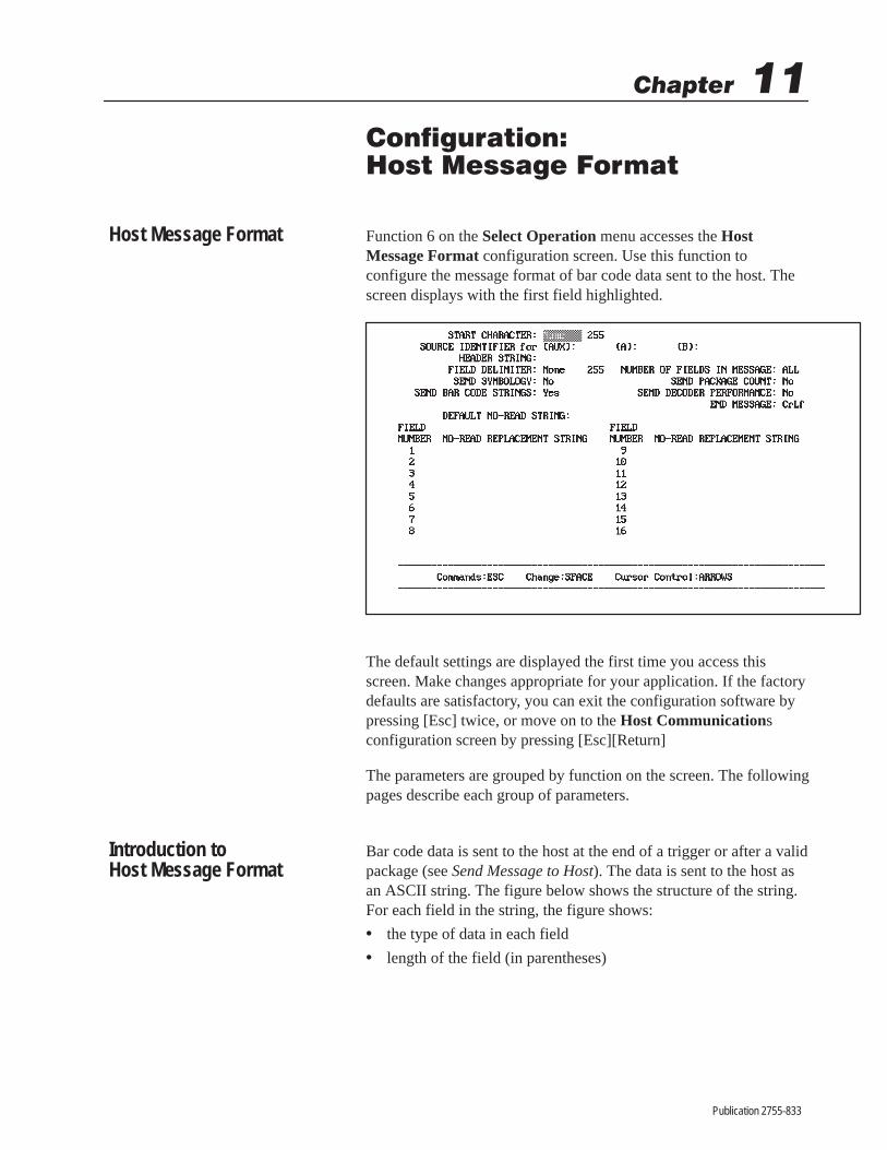
������ ��
Publication 2755-833
�� ������� �������������������
Function 6 on the Select Operation menu accesses the HostMessage Format configuration screen. Use this function toconfigure the message format of bar code data sent to the host. Thescreen displays with the first field highlighted.
The default settings are displayed the first time you access thisscreen. Make changes appropriate for your application. If the factorydefaults are satisfactory, you can exit the configuration software bypressing [Esc] twice, or move on to the Host Communicationsconfiguration screen by pressing [Esc][Return]
The parameters are grouped by function on the screen. The followingpages describe each group of parameters.
Bar code data is sent to the host at the end of a trigger or after a validpackage (see Send Message to Host). The data is sent to the host asan ASCII string. The figure below shows the structure of the string.For each field in the string, the figure shows:
• the type of data in each field
• length of the field (in parentheses)
Host Message Format
Introduction toHost Message Format

11–2 Configuration: Host Message Format
Publication 2755-833
Some of the fields are controlled by the bar code itself. However,most of the fields are controlled by the host message configurationparameters. In addition, many of these same functions can beperformed using the Host Replacement Rules described earlier in thismanual.
Bar Code Host Message Format
ASCII BAR CODE DATA
11. End Message(0 to 3)
10. Performance Indi-cators. (0 or 6)
9. Package Count (0 or6–DD, 0 or 3–DS)
7. Field Delimiter (0 or 1)
6. Bar Code Data or No-Read Message (0 to 64 characters, including start, stop, andcheck characters. Up to 64 characters will be sent for each field read. (Codabar StopCharacter follows Codabar Check Characters (if sent).)
5. Symbology (0 or 2)
4. Field Delimiter (0 or 1)
3. Header Message (0 to 32)
2. Source Identifier (0 to 4)
1. Start Character (0 or 1)
8. Field Delimiter (0 or 1)
12. TransmissionCheck (0 to 2)
In messages containing multiple bar code data strings, each stringwill be separated by a single field delimiter. A double delimiterfollows the final string.
Below are some sample host messages to help you configure yourdecoder. The examples show data transmitted by the decoder. Theconfiguration parameters for the message were set up as follows:

11–3Configuration: Host Message Format
Publication 2755-833
Note: A double delimiter (two quotation marks in this example)indicate the end of bar code data.
Example 1: If one Code 39 label is decoded, the decoder transmits:
End Message CharactersPackage Count
End of Package Double Delimiter
Bar Code Data
Code 39 Symbology Type Indicator
Header Message
Field Delimiter
#L7–AData From Scanner A ” 01001122334455 ” ” 000013CRLF
Start CharacterSource Identifier
Example 2: If two Code 39 labels are scanned on a single package,the decoder transmits:
Source IdentifierStart Character
#L7-AData From Scanner A ” 01998877665 ” 01001122334 ” ” 000014CRLF
Header MessageEnd Message Characters
Package CountEnd of Package Double Delimiter
Bar Code DataCode 39 Symbology Type Indicator
Field Delimiter
Bar Code DataCode 39 Symbology Type Indicator
Field Delimiter

11–4 Configuration: Host Message Format
Publication 2755-833
Example 3: If a No-Read occurs, the decoder transmits:
End Message CharactersPackage Count
End of Package Double Delimiter
No-Read Message
Header Message
Field Delimiter
#L7–AData From Scanner A ” NO-READ ” ” 000015CRLF
Start CharacterSource Identifier
Note: Message packages can consist of both bar code strings andno-read strings.
The parameters listed below include those used to control themessage format of bar code data that is sent to the host. Eachparameter is defined below. The options for each parameter aresummarized in a table, and explained more fully in the text. Whereappropriate, the default setting for each parameter is displayed inbold letters in the table.
Start Character
Field Type Options
Edit NumericASCII Numeric (1 – 255)255 = None
Defines the three digit decimal ASCII starting character for every barcode message sent to the host. The default is None or 255, whichindicates no start character.
Source Identifier for AUX, A, and B
Field Type Options
Edit Text
Any ASCII Character String (4 chars max)Blank
Defines a 1 to 4 character identifier to include in each message sentto the host. The string identifies the source device for the datacontained in the message. The default for each field is Blank, whichmeans a source identifier is not defined. Example source identifiersare SCNA, SCNB, and AUX.
Host Message Parameters

11–5Configuration: Host Message Format
Publication 2755-833
The source identifier may be unique for Scanner A, Scanner B andthe AUX terminal to identify the data source.
Header Message
Field Type Options
Edit Text
Any ASCII Character String (32 chars max)Blank
Defines a 1 to 32 character header message to include in eachmessage sent to the host. The default is Blank, which means a headermessage is not defined. An example header message is BAR CODEDATA.
Field Delimiter
Field Type Options
Edit NumericASCII Numeric (1 – 255)255 = None
Defines the three digit decimal ASCII character that will indicate thebeginning and end of bar code label data. If multiple symbols arebeing read, the delimiter also separates each field in the message. Adouble delimiter (two consecutive occurrences of a delimitercharacter) indicates the end of a package.
The default is None or 255, which means no delimiter is defined.When choosing a delimiter, be careful to select a character that willnot appear in the bar code data.
Number of Fields in Message
Field Type Options
Edit Numeric 1 through 160 = All
Determines the number of bar code symbols to include in eachmessage. The default All sets the value to equal the number ofsymbols per package. The values 1 through 16 will set this value to aspecific number of fields. (See Symbols Per Package, Chapter 7, andHost Replacement Rules: Host Message Field Number, Chapter 10,for more information.)

11–6 Configuration: Host Message Format
Publication 2755-833
Send Symbology
Field Type Options
Select YesNo
Controls whether the symbology type of the bar code is included inthe message sent to the host. The default is No, which means thesymbology type is not sent to the host.
If you select Yes, the symbology type is transmitted as a two digitcode:
00 Keyboard Data from AUX Terminal
01 Code 39
02 Interleaved 2-of-5
03 Codabar
04 UPC-A
05 UPC-E
06 EAN-8
07 EAN-13
08 Code 128
09 Pharma-Code
Send Package Count
Field Type Options
Select YesNo
Controls whether the package count is included in the message sentto the host. The default is No, the package count is not sent to thehost.
The six digit package count is maintained by the package counter.Counter data can also be sent to the host when requested by a hostcommand as described elsewhere in this manual.
Send Bar Code Strings
Field Type Options
Select YesNo
Controls whether bar code data is sent to the host. The default of Yessends bar code data to the host.

11–7Configuration: Host Message Format
Publication 2755-833
Send Decoder Performance
Field Type Options
Select YesNo
Controls whether the performance indicators for Scanners A and Bare included in the message sent to the host. The default is No, theperformance indicators are not sent to the host.
The performance indicator is a three digit value for DS units, and asix digit value for DD units. The first three digits apply to ScannerA, and the last three digits apply to Scanner B.
End Message
Field Type Options
Select
NoneCRLFCRLFETXCRETXLFETXCRLFETX
Defines an ASCII control code to terminate or end each message sentto the host. The default is CRLF, which terminates each messagewith a carriage return and line feed.
Default No-Read Message
Field Type Options
Edit Text
Any ASCII Character String (32 chars max)Blank
Defines a 1 to 32 character no-read message to include in eachmessage sent to the host when a no-read occurs and a specificno-read message has not been defined for that field (see below). Thedefault is Blank, which means a default no-read message string is notdefined. An example no-read message is NO-READ.

11–8 Configuration: Host Message Format
Publication 2755-833
No-Read Replacement Strings
Field Type Options
Edit Text
Any ASCII Character String (32 chars max)Blank
If the rules are active (See Chapter 10), defines a 1 to 32 characterstring to include in the message sent to the host. These strings aresent when a no-read or a specific host replacement rule is notsatisfied for a specific field (1 through 16). The default is Blank,which means a no-read replacement string is not defined for thatfield. If a no-read does occur, or a replacement rule fails, the defaultno-read message (if one is defined) will be sent.
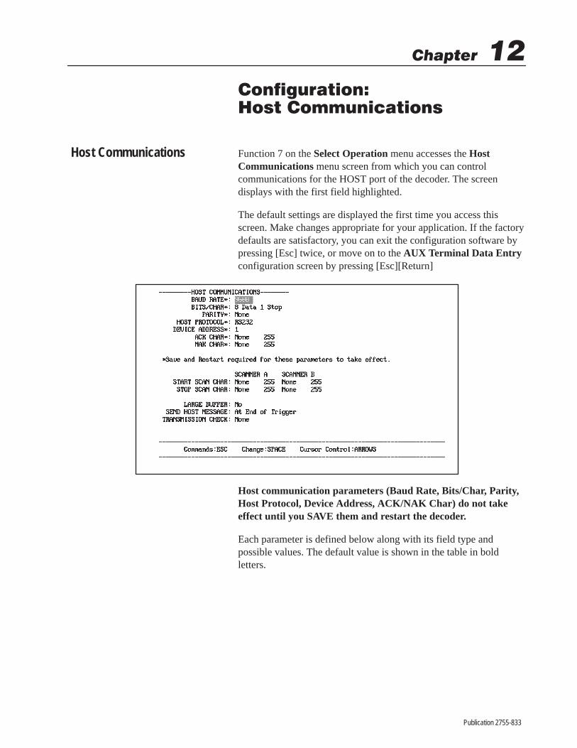
����� ��
Publication 2755-833
������ ��������������������
Function 7 on the Select Operation menu accesses the HostCommunications menu screen from which you can controlcommunications for the HOST port of the decoder. The screendisplays with the first field highlighted.
The default settings are displayed the first time you access thisscreen. Make changes appropriate for your application. If the factorydefaults are satisfactory, you can exit the configuration software bypressing [Esc] twice, or move on to the AUX Terminal Data Entryconfiguration screen by pressing [Esc][Return]
Host communication parameters (Baud Rate, Bits/Char, Parity,Host Protocol, Device Address, ACK/NAK Char) do not takeeffect until you SAVE them and restart the decoder.
Each parameter is defined below along with its field type andpossible values. The default value is shown in the table in boldletters.
Host Communications

12–2 Configuration: Host Communications
Publication 2755-833
Baud Rate
Field Type Options
Select
96004800240012003001920038400
Selects the baud rate (data transmission speed) for the HOST port.The default is 9600 the first time the decoder is started. From thenon, operation is determined at restart by the contents of storagememory.
Bits/Char
Field Type Options
Select
8 Data 1 Stop8 Data 2 Stop7 Data 1 Stop7 Data 2 Stop
Selects the number of data and stop bits transmitted with eachcharacter via the HOST port. The default is 8 Data Bits, 1 Stop Bitthe first time the decoder is started. From then on, operation isdetermined at restart by the contents of storage memory.➀
Parity
Field Type Options
SelectNoneEvenOdd
Selects the parity bit for each character transmitted or received at theHOST port. The default is None the first time the decoder is started.From then on, operation is determined at restart by the contents ofstorage memory.
➀ The contents of storage memory can be reviewed by performing a Recall. Parameters are saved to smemory with the Save command.

12–3Configuration: Host Communications
Publication 2755-833
Host Protocol
Field Type Options
Select
RS232RS232 XON/XOFFRS232 CTS/RTS – 1RS232 CTS/RTS – 2RS422 RS422 XON/XOFFDH485 PCCC – 1DH485 PCCC – 2DH485 ASCII – 1DH485 ASCII – 2
Selects a communication interface and protocol for the HOST port.The default is RS-232 (with no flow control) the first time thedecoder is started. From then on, operation is determined at restartby the contents of storage memory.
Other options include:
• RS232 XON/XOFF uses XON/XOFF flow control
• RS232 CTS/RTS-1 uses half duplex RTS, CTS and DTR modemcontrol lines to control the flow of data from the decoder to thehost.
• RS232 CTS/RTS-2 uses RTS, CTS and DTR modem control linesfor bidirectional (full duplex) flow control between the decoderand the 2760-RA/RB module (when the module has modemcontrol enabled).
• RS422 (no flow control) uses no flow control.
• RS422 XON/XOFF uses XON/XOFF flow control.
• DH485 PCCC-1 uses PCCC commands with write replies.
• DH485 PCCC-2 uses PCCC commands without write replies.
• DH485 ASCII-1 uses ASCII commands with responses.
• DH485 ASCII-2 uses ASCII commands without responses.
Device Address
Field Type Options
Edit Numeric 00 through 3101
Specifies the node address of the decoder if operating as a node onan RS-485 network. Each node on the network must have a uniquenode address from 00 to 31. The default device address for thedecoder is 01 the first time the decoder is started. From then on,operation is determined at restart by the contents of storage memory.
12–4 Configuration: Host Communications
Publication 2755-833
ACK Character
Field Type Options
Edit ASCII 0 through 255255 = None
Defines an Acknowledge (ACK) character for ACK/NAK protocol.The first time the decoder is started, the default is None, whichmeans an ACK character is not defined. From then on, the default isdetermined at restart by the contents of storage memory.①
The ACK character is sent by the host to acknowledge receipt of amessage. The decoder holds the last transmitted message until anACK is returned to the decoder. Any command the decoder receivesfrom the host is also interpreted as an ACK character.
You must define ACK and NAK characters to enable ACK/NAKprotocol with the host. ACK/NAK protocol only applies to barcode data sent to the host. It is typically used with thetransmission check to provide error detection. You can also useACK/NAK protocol to provide flow control.
NAK Character
Field Type Options
Edit ASCII 0 through 255255 = None
Defines a Negative Acknowledge (NAK) character for ACK/NAKprotocol. The first time the decoder is started, the default is None,which means a NAK character is not defined. From then on, thedefault is determined at restart by the contents of storage memory.①
The NAK character is sent by the host when a message is notreceived properly and prompts the decoder to retransmit the lastmessage up to three times.
① If any of the characters below are used as single character commands (ACK/NAK or Start/Characters), then the escape sequence (ESC=!) must be used with all two character commstart with that character.
A B C D H I M N O P R S T
If the single character commands do not use these uppercase characters, you do not have tostart command sequence. For example, if N is used as the NAK command, then it would bimpossible to send the NR command without preceding it with the ESC=! start command sIf n is used instead, then no start command sequence would be necessary to send an NR coTherefore, we recommend using only lowercase letters for single character command
Refer to Chapter 15 for additional information.

12–5Configuration: Host Communications
Publication 2755-833
You must define ACK and NAK characters to enable ACK/NAKprotocol with the host. ACK/NAK protocol only applies to barcode data sent to the host. It is typically used with thetransmission check to provide error detection. You can also useACK/NAK protocol to provide flow control.
Start Scan Character
Field Type Options
Edit ASCII 0 through 255255 = None
This parameter is used with the stop scan character and only applieswhen the Decode Mode is set to Host.
Defines the character that tells the scanner(s) to start scanning. Thereis a field for both Scanner A and, if present, Scanner B. The defaultis None, which means a start scan character is not defined.①
Stop Scan Character
Field Type Options
Edit ASCII 0 through 255255 = None
This parameter is used with the start scan character and only applieswhen the Decode Mode is set to Host.
Defines the character that tells the scanner(s) to stop scanning. Thereis a field for both Scanner A and, if present, Scanner B. The defaultis None, which means a stop scan character is not defined.①
① If any of the characters below are used as single character commands (ACK/NAK or Start/Characters), then the escape sequence (ESC=!) must be used with all two character commstart with that character.
A B C D H I M N O P R S T
If the single character commands do not use these uppercase characters, you do not have tostart command sequence. For example, if N is used as the NAK command, then it would bimpossible to send the NR command without preceding it with the ESC=! start command sIf n is used instead, then no start command sequence would be necessary to send an NR coTherefore, we recommend using only lowercase letters for single character command
Refer to Chapter 15 for additional information.

12–6 Configuration: Host Communications
Publication 2755-833
Large Buffer
Field Type Options
Select YesNo
Enables or disables use of the 8K byte buffer on the HOST port. Thedefault is No, which disables use of this buffer.
The 8K byte buffer allows the decoder to decode and buffermessages to the host. This feature is useful for applications where thehost is incapable of handling high burst rates of data from thedecoder. If No is selected, the decoder will only buffer one message.
!ATTENTION: Do not use the large buffer if the datasent to the host must be coordinated with the outputmodules, because the buffering may delay receipt ofthe data by the host.
Send Message to Host
Field Type Options
SelectAt End of TriggerImmediately After Valid Package
Specifies when the decoder sends data to the host or activates anoutput module. The default is At End of Trigger.
The end of trigger condition is determined by the decode mode. Theend of trigger conditions for the triggered decode modes are:
Timing Host Package Detect Internal Timer
End of Trigger(send message to
o t
Stop scan character Detect signal goesinactivend a to
hostat end of trigger)
No-read timer ex-pires
No-read timer ex-pires
No-read timer ex-pires
Immediately AfterValid Package
Symbols/packagecount met
Symbols/packagecount met
Symbols/packagecount met
The response mode for the continuous and continuous/unique decodemodes is always Immediately After Valid Package. The decodersends data and activates the outputs immediately after a validpackage (symbols/package count is met) or a no-read, whichevercomes first. Use this mode for maximum speed.

12–7Configuration: Host Communications
Publication 2755-833
Transmission Check
Field Type Options
Select
NoneLRCChecksum – LSBChecksum – MSB
Specifies the type of transmission check that is generated at the endof a message sent to the host. The default is None, which means notransmission check is generated.
The decoder can generate three types of transmission checks:
1. LRC (Longitudinal Redundancy Check). A byte developed byan exclusive OR of all bytes in a message.
2. Checksum–MSB. Sixteen bit sum of all the bytes in a messagewith the most significant byte transmitted first.
3. Checksum–LSB. Sixteen bit sum of all the bytes in a messagewith the least significant byte transmitted first.
Appendix C provides an example of a transmission check.
Do not use XON/XOFF flow control with transmission check. Thetransmission check bytes could be interpreted as an XOFF character.

����� ��
Publication 2755-833
����� �������������������� �����
The terminal connected to the AUX port can be used for eitherconfiguration or manual data entry and display operations. We referto this terminal as the AUX terminal. This chapter describes how toconfigure and use the AUX terminal for manual data entry anddisplay operations. Topics include:
• supported terminals for manual data entry
• configuration for AUX terminal data entry
• how to enable manual data entry mode
• how to display bar code data, decoder performance and countervalues
• how to display host messages
• how to perform manual data entry at the keyboard
Any terminal that supports the following features can be used formanual data entry or display operations at the AUX port:
• Carriage Return and Line Feed
• 9600 Baud Rate
• 8 Data Bits
• 1 Stop Bit
• Parity None
• XON/XOFF Flow Control
Specific terminal types for data entry and display include:
• Allen-Bradley Industrial Terminal (Catalog No. 1771-T1, -T2,-T3)
• Allen-Bradley laptop computers (Catalog No. 1784-T45, –47,–48)
• Allen-Bradley 2708-DH5 Series of Attended Workstations
• DEC VT100
• Lear Siegler ADM 3E
Appendix D provides details on how to connect and setup theterminals listed above. To set the above communication parametersfor other types of terminals, refer to your terminal’s User Manual.
Chapter Objectives
Supported Terminals

13–2 Configuration: AUX Terminal Data Entry
Publication 2755-833
Function 8 on the Select Operation screen accesses the AUXTerminal Data Entry screen. Use this screen to configure the AUXterminal for manual data entry operations. These parameters are usedby the terminal when the AUX port is set to manual data entry (notconfiguration) mode.
Note: Manual data entry and configuration modes are mutuallyexclusive.
Each manual data entry parameter is defined below along with thefield type and possible values. The default value is shown in thetables in bold letters.
Enable Keyboard Entry
Field Type Options
SelectNoYesNo-Read
Enables or disables use of the terminal keyboard when the AUX portis set to manual data entry mode. The default is No, which disableskeyboard data entry.
No Disables the keyboard locally. However, the host canremotely enable the keyboard for one message usingthe Display Text Message command as explainedlater in this chapter.
Yes Enables the keyboard for data entry. Selecting Yesenables you to manually enter data at the keyboard.When entry is enabled, pressing [ESC] will cancelthe current entry.
AUX TerminalConfiguration

13–3Configuration: AUX Terminal Data Entry
Publication 2755-833
Data entered at the keyboard is sent to the host withthe AUX Port Source Identifier (if defined) andformatted according to the Aux Data Formatparameter. The data is either formatted like the hostmessage or is unformatted.
No-Read Enables the keyboard for data entry when a no-readoccurs for a package. Selecting No-Read allows youto manually enter a single string at the keyboard.
If a no-read occurs, the Default Prompt Messagedisplays (if defined) prompting you to act. You canalso use the Display Text Message host command atany time to manually prompt for data.
Data is sent to the host with the AUX Port SourceIdentifier (if defined) and formatted according to theAux Data Format parameter.
Note: For safety considerations, data entered at the keyboard cannotbe used to control the discrete I/O.
Confirm Entry
Field Type Options
Select NoYes
Specifies whether you are required to confirm a keyboard entry bytyping the data a second time. The default is No, confirmation is notrequired.
Select Yes to require that data entered at the keyboard be entered asecond time. Data must be entered twice consecutively in exactly thesame way before it is sent to the host.
Entering the data twice helps ensure data integrity. Errors are morelikely to occur with data that is manually entered than scanned, but itis unlikely that one will make identical typing errors in succession.Simply press [ENTER] twice in succession to send no message (withthe end message character).
13–4 Configuration: AUX Terminal Data Entry
Publication 2755-833
AUX Data Format
Field Type Options
Select UnformattedHost Format
Controls the format of data sent to the host from the keyboard. Thedefault is Unformatted; the data, with the AUX Source ID prefix (ifdefined), is sent in the same form it was entered.
Select Host Format to send the data in the host message format setby the parameters on the Host Message Format configurationscreen. The host format packages the manually entered data as if itwere scanned. The source identifier for the AUX terminal (ifdefined) will distinguish manually entered data from scanned data. IfSend Symbology is enabled, “00” will be sent for data entered at theAUX terminal. (Also see Host Message Replacement Rules, Chapter10.)
Rubout Character
Field Type Options
Edit ASCII 0 through 255008 BS
Defines the terminal character that allows you to delete the previouscharacter during keyboard data entry. The default is backspace(decimal ASCII 008). To define a different rubout character, enter anumeric value between 0 and 255.
Echo To Terminal
Field Type Options
Select NoYes
Controls whether data entered at the keyboard is displayed (echoed)on the terminal display. The default is No, keyboard data is notechoed.
If the terminal itself is set to echo data, select No to prevent theterminal from displaying duplicate characters; otherwise, select Yes.

13–5Configuration: AUX Terminal Data Entry
Publication 2755-833
Size of Display
Field Type Options
Edit Numeric 10 through 8080
Defines the maximum number of characters that can display on oneline of the terminal display. The default is 80, which means up to 80characters can display on one line. The typical display size is 80. Tospecify another display size, enter a value between 10 and 80.
Default Prompt Message
Field Type Options
Edit TextASCII Text to 20 Characters MaxBlank
Defines a 1 to 20 character message that displays on the terminalprompting you to enter keyboard data or take some other action. Themessage always starts at position 1 on the display. The default isBlank, which means a prompt message is not defined.
This message is displayed when Enable Keyboard Entry is set toNo-Read and a no-read occurs. It is also displayed when EnableKeyboard Entry is set to No and the host remotely enables thekeyboard for one message using the Display Text Message command.If this command is sent with a zero length string (no message), theDefault Prompt Message is displayed.
The AUX terminal port is set for configuration operations at thefactory. To enable the AUX terminal for manual data entry (insteadof configuration), use one of the AUX Terminal Selectors.
The AUX Terminal Selectors allow you to switch betweenconfiguration and manual data entry operations using one of twomethods:
• Internal Selector (jumper on main logic board)
• External Selector (pin connections on AUX port connector)
Note: Manual data entry and configuration modes are mutuallyexclusive.
Switching to ManualData Entry Mode

13–6 Configuration: AUX Terminal Data Entry
Publication 2755-833
Internal Selector
The Internal Selector is a jumper on the main logic board, labelledAUX Terminal. The figure below shows the location of this jumperon the board.
Internal Selector (AUX Terminal Jumper)
Main Logic Board
Enclosure
LCD DISPLAYCONTRAST
ADJUST
AUX TERMINAL
DATA CONFIG.ENTRY
Internal Selector
∨∨
The jumper has two positions, which determine the mode ofoperation that is enabled for the AUX port terminal.
CONFIG (Jumper Right)
With the jumper positioned as shown on the upper left, you can usethe AUX terminal for configuration only. Configuration menus andscreens are enabled. This is the factory default setting.
DATA ENTRY (Jumper Left)
With the jumper positioned as shown on the lower left, you can usethe AUX terminal for manual data entry and display functions only.Configuration menus and screens are disabled.
External Selector
The other way to switch from configuration to manual data entrymode is to connect pins 15 and 16 (NEMA Type 1) or G and H(NEMA Type 4) in the AUX port connector. See Chapter 4 for adescription of the AUX port connector pins.
AUX TERMINAL
DATA CONFIG.ENTRY
Default∨∨
AUX TERMINAL
DATA CONFIG.ENTRY
∨∨

13–7Configuration: AUX Terminal Data Entry
Publication 2755-833
Note: If either the external selector or the the internal selector isset to data entry, the decoder will be in manual data entry mode,and will not display the Configuration screens.
After switching to manual data entry mode, you can:
• Display bar code data, decoder performance indicators, counterdata, and host messages on the AUX terminal.
• Enter data at the AUX terminal keyboard.
Both of these operations are controlled by parameters on the AUXand LCD Display Format and AUX Terminal Data Entryconfiguration screens. The parameters defining display parametersare discussed in Chapter 9.
The sections that follow show how these parameters directly affectthe display of data on the AUX terminal, and control the type of dataentry operations that are allowed at the AUX terminal.
This section shows how to configure the AUX terminal for displayoperations. You can configure the AUX terminal to display:
• Bar code data
• Decoder performance indicators
• Counter data
• Host messages
The parameters on the AUX and LCD Display Formatconfiguration screen determine what data is displayed, where thedata is displayed, and on which device. Detailed definitions of theseparameters appear in Chapter 9.
Data Entry andDisplay Operations
Displaying Data at theAUX Terminal

13–8 Configuration: AUX Terminal Data Entry
Publication 2755-833
Displaying Host Messages
The AUX terminal can display text messages that are sent from thehost using the Display Text Message command. Typically, thiscommand is used during manual data entry to prompt the user toenter bar code data or take some other action. The last section in thischapter describes manual data entry operations.
To accommodate the many variations in display terminals, messagessent from the host always display in position 1.
If the host sends the Display Text Message command to the decoderwith a text string length set to zero, the decoder will display theDefault Prompt Message instead (if defined). The text string fromthe host and the default prompt message are always preceded by acarriage return and line feed, and display at the beginning of the linein position 1.
The following parameter defines the Default Prompt Message:
Defines 1 to 20 character prompt message.Initially, the default prompt message is undefined.
The amount of data to be displayed is restricted by the size of theterminal display. For example, most terminals support an 80character display. Formatted data (other than host messages) thatexceeds the size of the display is truncated. Text messages from thehost that are longer than the size of the display will truncate.
Processing No-Reads
This section includes some examples to illustrate how the decoderhandles subsequent packages while waiting for you to respond to ano-read. All examples assume that manual data entry is enabled onlyfor no-reads and the Default Prompt Message is defined as ” EnterCarton Data:”.
Example 1: What happens if you respond to a no-read before thenext package arrives?
If you complete the data entry process for a no-read before the nextpackage arrives, the package count of the manually entered data(which is sent to the host if the data is host formatted) will be thesame as the no-read package.

13–9Configuration: AUX Terminal Data Entry
Publication 2755-833
AUX Terminal ScreenDecoder Operations
Enter Carton Data:
no-read
Package 1
Sends Default Prompt Message to AUX Terminal
12345
Host Recieves
no-read
Packag
12345
1
1Keyboard enabled for package 1 no-read.
Example 2: What happens if you have not completed enteringthe data at the keyboard and the next package arrives?
If the next package is a valid read, it will be sent to the discretes I/Oand the host. The package count will increment. This will continuewith each subsequent valid read. When the manual data entry iscomplete, it will be sent to the host with the package count of the lastpackage read.
AUX Terminal ScreenDecoder Operations
Enter Carton Data:
no-read
Package 1
Sends Default Prompt Message to AUX Terminal
1234
Host Recieves
no-read
Package C
1
Package 2
12345
Not completed before package 2 arrives.
Keyboard enabled for package 1 no-read.
Data entry started.76543 76543 2
Enter Carton Data:12
Data entry continues.Not complete before package 3 arrives
Package 3
24678 24678Data entry complete.
3
3
If the next package (or any of the packages processed before themanual data entry is completed) is a no-read, the decoder will sendonly a single message. The opportunity for entering data foradditional no-reads that occurred during manual data entry will belost. In other words, if you can enter data manually more quicklythan no-reads occur, then you will lose no data. If two no-reads occurbefore you have completed entering data for the first, then you willhave no opportunity to enter data for the second no-read in thesequence.

13–10 Configuration: AUX Terminal Data Entry
Publication 2755-833
AUX Terminal ScreenDecoder Operations
Enter Carton Data:
no-read
Package 1
Sends Default Prompt Message to AUX Terminal
12
Host Recieves
no-read
Package C
1
no-read
Package 2
no-read 2
12345 2
Completed after package 2 arrives.
Keyboard enabled for package 1 no-read.
Data entry started.
The opportunity to enter data for the Package 2 no-read is lost.
Important: To process a no-read and guarantee that the packagecount of the manually entered data corresponds to the scanned data,prevent future triggers from occurring. You can configure a discreteoutput for the no-read condition or a host message containing”no-read” to prevent subsequent packages from being processed.
ASCII Commands
The Display Text Message (TM) command allows you to send amessage to the AUX terminal and optionally enable the AUXterminal keyboard for one entry.
The following TM command sends the message ”START JOB!” butdoes not enable the keyboard.
TM010START JOB!
Message Text String = START JOB!
Length of Text String = 10
Keyboard Not Enabled = 0
Command Code = TM
When the host sends this command to the decoder, the text stringdisplays on the AUX terminal at the beginning of the line in position01.
START JOB!
Messages that are longer than the size of the AUX terminal displaytruncate.
Using ASCII andPCCC Commands

13–11Configuration: AUX Terminal Data Entry
Publication 2755-833
If the TM command is sent with a string length of zero (no messagedefined), the decoder displays the Default Prompt Message instead.
The following TM command sends the message ”ENTER DATA:” tothe AUX Terminal and enables the keyboard for one entry.
TM111ENTER DATA:
Message Text String = ENTER DATA:
Length of Text String = 11
1 = Enables Keyboard for Data Entry
Command Code = TM
When the host sends this command to the decoder, the following textstring displays on the AUX terminal prompting you to enter data.The message displays at the beginning of the line in position 01.
ENTER DATA:
If the TM command is sent without a message defined, the decoderdisplays the Default Prompt Message instead.
Messages that are longer than the size of the AUX terminal displaytruncate.
When receiving the host or default prompt message, the keyboard isenabled for one entry. Type the data and press [Enter].
ENTER DATA: 123456 [Enter]
After pressing [Enter], the keyboard is immediately disabled untilreceiving the next host command. To cancel the data entry operationwithout entering data, press [Esc].
Format of Manually Entered Data
After entering data, the decoder sends it to the host. The format inwhich the data is sent is controlled by the AUX Data Formatparameter, which is described earlier in this chapter.
PCCC Commands
You can also send a PCCC command to the decoder to display amessage at the AUX terminal and optionally enable the AUXterminal keyboard.

13–12 Configuration: AUX Terminal Data Entry
Publication 2755-833
The following PCCC command sends the message ”START JOB!”to the AUX terminal. The command address 900H sends a messagefor display, but does not enable the keyboard. Bytes 6 – 15 in theexample below define the characters of the message
.
0
5
STS= 00H
TNS
High Byte Low ByteMSB LSB
1
3 2
8
CMD= 08H
Display Message at AUX Terminal (900H)
Command Address = 900H 4
7 ”T” ”S”
10
9 ”R” ”A”
12
11 ” ” ”T”
14
13 ”O” ”J”
15 ”!” ”B”
6
Messages that are longer than the size of the AUX terminal displaywill truncate.
When the host sends this command to the decoder, the messagedisplays on the AUX terminal at the beginning of the line in position01.
START JOB!
If the PCCC (900H) command is sent with a string length of zero (nomessage defined), the decoder displays the Default Prompt Messageinstead.
The following PCCC command sends the message ”ENTERCARTON DATA:” to the AUX terminal and enables the keyboardfor data entry. The command address 901H distinguishes thiscommand function from the 900H command. Bytes 6 – 23 define thecharacters of the message.
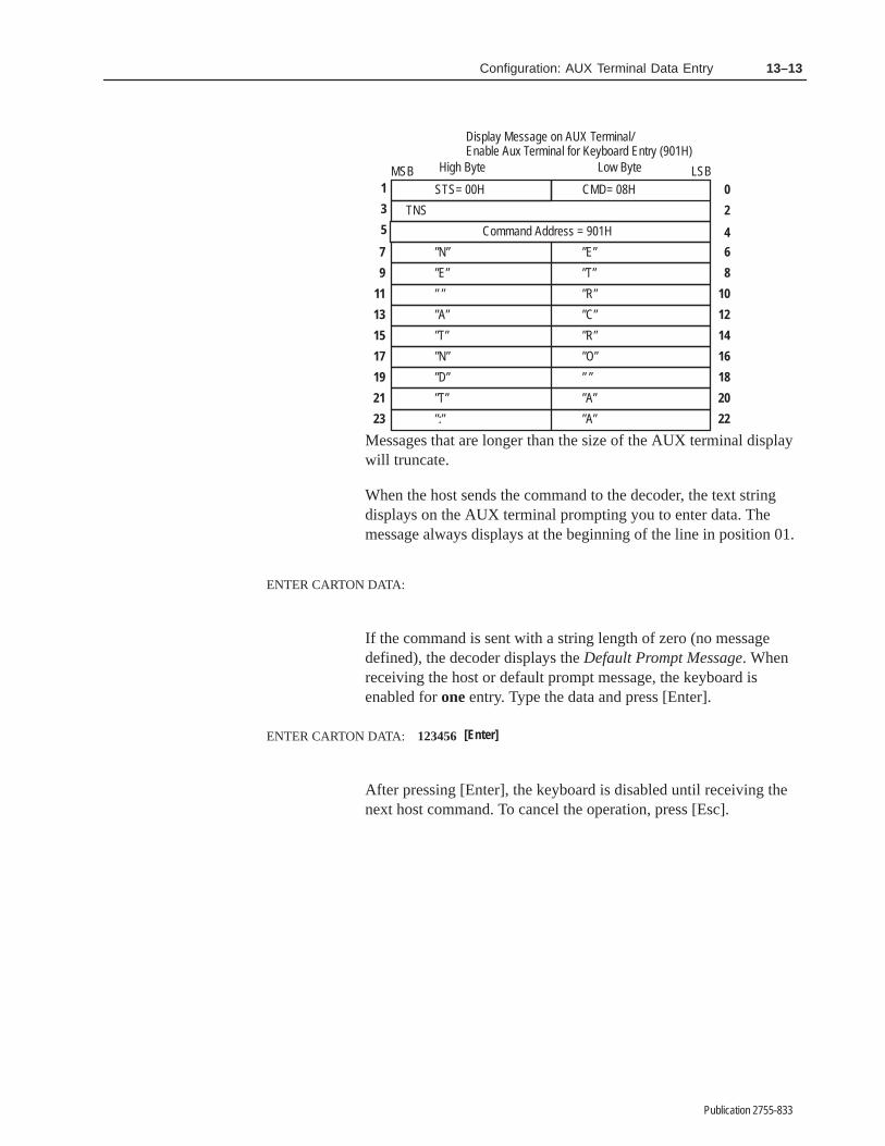
13–13Configuration: AUX Terminal Data Entry
Publication 2755-833
0
5
STS= 00H
TNS
High Byte Low ByteMSB LSB1
3 2
8
CMD= 08H
Display Message on AUX Terminal/Enable Aux Terminal for Keyboard Entry (901H)
Command Address = 901H 4
7 ”N” ”E”
10
9 ”E” ”T”
12
11 ” ” ”R”
14
13 ”A” ”C”
16
15 ”T” ”R”
18
17 ”N” ”O”
20
19 ”D” ” ”
22
21 ”T” ”A”
23 ”:” ”A”
6
Messages that are longer than the size of the AUX terminal displaywill truncate.
When the host sends the command to the decoder, the text stringdisplays on the AUX terminal prompting you to enter data. Themessage always displays at the beginning of the line in position 01.
ENTER CARTON DATA:
If the command is sent with a string length of zero (no messagedefined), the decoder displays the Default Prompt Message. Whenreceiving the host or default prompt message, the keyboard isenabled for one entry. Type the data and press [Enter].
ENTER CARTON DATA: 123456 [Enter]
After pressing [Enter], the keyboard is disabled until receiving thenext host command. To cancel the operation, press [Esc].

����� ��
Publication 2755-833
������ � ���������� ������
This chapter describes how to use the bar code decoder configurationsoftware to:
• Display bar code strings
• Display decoder performance indicators and counters
• Reset status and counters
• Restart the system
• Select a new language option
• Save the current configuration.
To use the built-in configuration menus and screens, you must firstconnect a terminal to the RS-232 AUX port of the decoder.
Appendix D provides details on how to connect and setup eachterminal. The AUX port communication parameters are:
• 8 Data Bits
• 1 Stop Bit
• 9600 Baud Rate
• Parity None
• XON/XOFF Flow Control
Refer to Chapter 5 for information on getting started with the AUXcommunication software.
Chapter Objectives
Connect and Set UpAUX Terminal

14–2 Display and System Configuration
Publication 2755-833
The Display Bar Code Strings function on the Select Operationmenu allows you to monitor bar code labels as they are decoded.
To select this function, press the “A” or “a” key. The screen willclear and display decoded bar code strings. You might see:
The data from each string displays on a separate line. If severalsymbols are decoded in one scan, the symbols are displayed on asingle line, separated by a space.
Display Bar Code Strings

14–3Display and System Configuration
Publication 2755-833
Each line displays a maximum of 80 characters. If the data consistsof more than 80 characters, it continues to the next line until theentire string is displayed.
If the decoder is unable to decode a bar code label, the no-readmessage (if defined during configuration) is displayed.
The display continuously scrolls upward, displaying new bar codedata at the bottom of the screen.
To exit this function and return to the Select Operation menu, press[ESC].
The Display Status and Primary Counters function on the SelectOperation menu allows you to monitor system status and countersmaintained by the decoder.
To select this function, press the “B” or “b” key. The followingscreen displays:
Display Status andPrimary Counters

14–4 Display and System Configuration
Publication 2755-833
The decoder performance indicators and counters are updated on thedisplay once each second. Following is a description of each displayitem.
Decoder Performance(Scanner A and B)
In continuous mode, the performance indicators display thepercent of decoded scans for each scanner.
In triggered mode, the performance indicators display thenumber of valid scans (up to 100) during a trigger activeperiod for Scanner A and Scanner B.
Note: The decoder performance will never exceed thecapture count if Send Message to Host is set to ImmediatelyAfter Valid Package.
Decoder performance indicators are useful during:
- initial setup (when the decoder is in continuous mode) to determine the optimum location of the scanner relativeto the bar code labels.
- decoder operation to identify a decrease in performance.For example, if the number of good reads drops significantly, the label quality may have degraded or the scan head window may require cleaning.
Note: If a buffer overflow occurs while collecting data forthe sample scans, the value 999 displays until the conditionis corrected. This occurs if host communications is suspended.
Symbols Not ReadCounter
Displays the number of symbols not read in the triggeredmode of operation.
A no-read occurs when the decoder does not decode thecorrect number of symbols on a package as defined by theSymbols per Package parameter.
The counter increments for each symbol not read in apackage.
Package Counter Displays the number of packages detected by the decoder.
The package counter increments each time a trigger isgenerated by the package detector, a host command, or theinternal timer. It also increments each time a package is readin the continuous or continuous/unique operation modes.
Primary Counters(1-8)
Displays the number of output conditions that occur for eachdiscrete output (1-8).
Each output counter increments when a TRUE conditionoccurs for that output.

14–5Display and System Configuration
Publication 2755-833
The counters are six digit values that increment up to 999999. Whenexceeding 999999, the display automatically advances to 000000.
To exit this function and return to the Select Operation menu, press[ESC].
Resetting the Counters
You can reset the decoder status and counters to zero from theDisplay Status and Counters screen. You can reset individualcounters by pressing a number 1 through 8, and answering [Y] to theconfirmation request that appears on the bottom of the screen.
You can reset reset the decoder status and all primary counters tozero by pressing the [Space] bar. Press [Y] to reset the status andcounters. Press [N] or [Esc] to cancel the operation. This operation isidentical to the Reset Status and Counters function on the SelectOperation menu.
Note: The counters also reset when you restart the system withfunction Restart System.
There is a second way to reset the decoder performance indicatorsand all counters to zero from the Select Operation menu, select theReset Status and Primary Counters function. Press the “C” or “c”key. Press [Y] to reset the decoder performance indicators andcounters to zero. Press [N] or [Esc] to cancel the operation. Thisoperation is identical to pressing [Space] on the Display Status andCounters screen.
The Restart System function allows you restart the decoder. Thisoperation reboots the decoder, enables autoload functions, andenables lotting, and activates certain host communicationsparameters (Refer to Chapter 12).
To restart the decoder, press the “E” or “e” key. Press [N] or [Esc] tocancel the operation and return to the Select Operation menu. Press[Y] to restart the decoder.
During a restart, all configuration parameters are reset to the valueslast saved to storage memory, and the Select Language screen isdisplayed.
Restart System

14–6 Display and System Configuration
Publication 2755-833
The Select Language function allows you to access the SelectLanguage screen. Press the “F” or “f” key from the SelectOperation menu.
Press the number key that corresponds to the language you want touse. All subsequent screens display in the selected language.
To save the current system settings in storage memory, type “G” or“g” or select Save Configuration on the Select Operation menu.Press [N] or [Esc] to cancel the save operation and return to theSelect Operation menu. Press [Y] to save the current configuration.All configuration parameters are saved to storage memory.
Select Language
Save Configuration

����� ��
Publication 2755-833
����� ��� �����
This chapter defines ASCII commands you can send from a host tothe decoder using the RS-232, RS-422, or DH485 communicationinterfaces.
The RS-232, RS-422, and DH485 interfaces allow you to send singleor two character ASCII commands from the host to the decoder. Allcommands and command responses are ASCII character strings.
The single character commands control scanning (Start/Stop Scancharacters), and the transmission (ACK/NAK characters) of data tothe host. They are not used to configure or monitor decoderoperations. The single character commands are configured on theHost Communications screen described elsewhere in this manual.
The two character commands perform the same functions as thesettings on the configuration screens, and can be used to configureand monitor decoder operations. The rest of this chapter defines thetwo character ASCII commands.
!ATTENTION: When controlling discrete outputslocally using AUX port configuration, suspend hostcommunications to prevent outputs fromunintentionally changing state.
The DH485 interface supports the two character ASCII commands.To use these commands, the decoder requires you to set the HostProtocol parameter on the Host Communications screen to one ofthe following:
• DH485 ASCII-1 Protocol with Responses
• DH485 ASCII-2 Protocol without Responses
Note: The DH485 ASCII-2 Protocol (without responses) reducesdata traffic on the link. Responses are unnecessary since the linklayer of the Allen-Bradley DH485 network insures that a commandis properly received.
The decoder supports the following DH485 communicationaddresses:
DH485 LSAP Function
0 Diagnostic Commands (Perform Application Layer)
1 or 128 ASCII Commands (Perform Application Layer)
129 Perform Link Reset-immediate Block
Chapter Objectives
Using RS-232/RS-422
Using DH485

15–2 ASCII Host Commands
Publication 2755-833
Table 15.A Two–character ASCII commands (grouped byfunction)
PageNumber
CommandCode Command Function
Symbologies
15–8 CT Configure Bar Code Symbology and Supplements
15–9 SL Configure Bar Code Specific Length
15–11 CC Configure Code 39, I 2-of-5, Codabar Check Characters
15–12 CG Configure I 2-of-5 Guard Bar
15–13 CQ Configure Quiet Zone
15–14 CF Configure Code 128 FNC1 Character
15–15 CV Configure Code Verification List
15–16 CP Configure Pharma–Code
Scanner Control
15–18 SC Configure Scanner A Control
15–20 PB Configure Scanner B Control
15–21 IF Configure Scanner A Package Detect Filter and Sense
15–22 BF Configure Scanner B Package Detect Filter and Sense
15–23 BL Configure Scanner B Laser Mode
Primary Match Code Table
15–24 SW Write Scanner Source to Match Code Table
15–25 AB Auto-load Begin
15–25 AE Auto-load End
15–26 AL Auto-load
15–28 OS Set Output Normally Open/Normally Closed
15–29 OC Set Output Condition and Duration
15–31 OH Hold Output Open/Closed
15–33 MR Read Primary Match Code Table Entry (1-8)
15–34 MW Write Primary Match Code Table Entry (1-8)
15–35 CM Clear Primary Counter (1-8)
15–36 CO Clear All Primary Output Counters
Extended Match Code Table
15–25 AB Auto-load Begin
15–25 AE Auto-load End
15–26 AL Auto-load
15–36 CA Clear Extended Match Counters
15–37 SE Set Extended Match Counter
15–38 RC Read Extended Match Counter
15–39 SM Set Extended Match Data
15–41 RP Read Extended Match Data
15–43 RA Read All Extended Counters
15–45 CS Disable Extended Match Code Set
15–46 RS Read Extended Match Set Status

15–3ASCII Host Commands
Publication 2755-833
PageNumber Command FunctionCommand
Code
AUX and LCD Display Format
15–47 DF Enable AUX Terminal and LCD to Display Formatted Data
15–48 DP Configure Data Display Positions for AUX Terminal and LCD
15–49 SD Enable LCD Scrolling
Host Message Replacement Rules
15–50 SR Set Search and Replace Rule for Host Message Fields
15–52 SF Set No-Read Replacement String
Host Communications & Host Message Format
15–53 HC Configure Host Communications
15–55 HB Configure Scanner B Start & Stop Characters
15–56 MF Configure Host Message Format
15–58 HF Set the Number of Fields in Host Message
15–59 IX Configure AUX Terminal Source Identifier
15–60 IM Configure Scanner A Source Identifier
15–61 IB Configure Scanner B Source Identifier
15–62 HM Configure Header Message
15–63 NM Configure Default No-Read String
AUX Terminal Data Entry
15–64 AX Configure AUX Terminal Data Entry Operations
15–66 TM Display Text Message at AUX Terminal and LCD
15–68 PM Configure Default Prompt Message for AUX Terminal and LCD
Status & Counters
15–69 PI Read Decoder Performance Indicators
15–70 PR Read Package Counter
15–71 NR Read the Symbols Not Read Counter
15–72 MC Read Output Counter
15–73 PC Clear Package Counter
15–73 NC Clear Symbols Not Read Counter
15–35 CM Clear Primary Counters (1–8)
15–36 CO Clear All Primary Output Counters
System Commands
15–74 RN Save Configuration to Storage Memory and Restart
15–74 SA Save Configuration to Storage Memory (No Restart)
15–75 DD Set Configuration to Factory Defaults
15–75 RD Set Configuration to Defaults, Save and Restart
15–76 RE Restart
15–76 ID Version of Software
Obsolete Commands (For Reference)
15–77 DM Configure Bar Code Data Mask
15–77 PD Configure Data Pad Character

15–4 ASCII Host Commands
Publication 2755-833
Table 15.B lists the two character ASCII commands inalphabetical order, by command code.
Table 15.B Two–character host commands (AlphabeticalOrder)
PageNumber
CommandCode Command Function
15–25 AB Auto-load Begin
15–25 AE Auto-load End
15–26 AL Auto-load
15–64 AX Configure AUX Terminal Data Entry Operations
15–22 BF Configure Scanner B Package Detect Filter and Sense
15–23 BL Configure Scanner B Laser Mode
15–36 CA Clear Extended Match Count
15–11 CC Configure Code 39, I 2-of-5, Codabar Check Characters
15–14 CF Configure Code 128 FNC1 Character
15–12 CG Configure I 2-of-5 Guard Bar
15–35 CM Clear Counter (1-8)
15–36 CO Clear All Primary Output Counts
15–16 CP Configure Pharma–Code
15–13 CQ Configure Quiet Zone
15–45 CS Disable Extended Match Code Set
15–8 CT Configure Bar Code Symbology and Supplements
15–15 CV Configure Code Verification List
15–75 DD Set Configuration to Factory Defaults
15–47 DF Enable AUX Terminal and LCD to Display Formatted Data
15–77 DM Configure Bar Code Data Mask
15–48 DP Configure Data Display Positions for AUX Terminal and LCD
15–55 HB Configure Scanner B Start & Stop Characters
15–53 HC Configure Host Communications
15–58 HF Set the Number of Fields in Host Message
15–62 HM Configure Header Message
15–61 IB Configure Scanner B Source Identifier
15–76 ID Version of Software
15–21 IF Configure Scanner A Package Detect Filter and Sense
15–60 IM Configure Scanner A Source Identifier
15–59 IX Configure AUX Terminal Source Identifier
15–72 MC Read Output Counter
15–56 MF Configure Host Message Format
15–33 MR Read Match Code Table Entry (1-8)
15–34 MW Write Match Code Table Entry (1-8)
15–73 NC Clear Symbols Not Read Counter
15–63 NM Configure Default No-Read String
15–71 NR Read the Symbols Not Read Counter
15–29 OC Set Output Condition and Duration
15–31 OH Hold Output Open/Closed
15–28 OS Set Output Normally Open/Normally Closed
15–20 PB Configure Scanner B Control
15–73 PC Clear Package Counter

15–5ASCII Host Commands
Publication 2755-833
PageNumber Command FunctionCommand
Code 15–77 PD Configure Pad Data Character (Obsolete Command)
15–69 PI Read Decoder Performance Indicators
15–68 PM Configure Default Prompt Message for AUX Terminal and LCD
15–70 PR Read Package Counter
15–43 RA Read All Extended Counts
15–38 RC Read Extended Match Count
15–75 RD Set Configuration to Defaults, Save and Restart
15–76 RE Restart
15–74 RN Save Configuration to Storage Memory and Restart
15–41 RP Read Extended Match Data
15–46 RS Read Extended Match Set Status
15–74 SA Save Configuration to Storage Memory (No Restart)
15–18 SC Configure Scanner A Control
15–49 SD Enable LCD Scrolling
15–37 SE Set Extended Match Count
15–52 SF Set Default Search Strings
15–9 SL Configure Bar Code Specific Length
15–39 SM Set Extended Match Data
15–50 SR Set Search and Replace Rule for Host Message Fields
15–24 SW Write Scanner Source to Match Code Table
15–66 TM Display Text Message at AUX Terminal and LCD
Command Format
The format or structure of the two character commands is:
1StartCommandSequence
2Command Code
3Parameters
4Terminator
1. Start Command Sequence. Contains the escape sequence<ESC>=!. The table below defines the ASCII and Hexadecimalequivalents of each character of the command sequence
ASCII and Hexadecimal Equivalents - Start Command Sequence
Character ASCII Hex
ESC 27 1B
= 61 3D
! 33 21
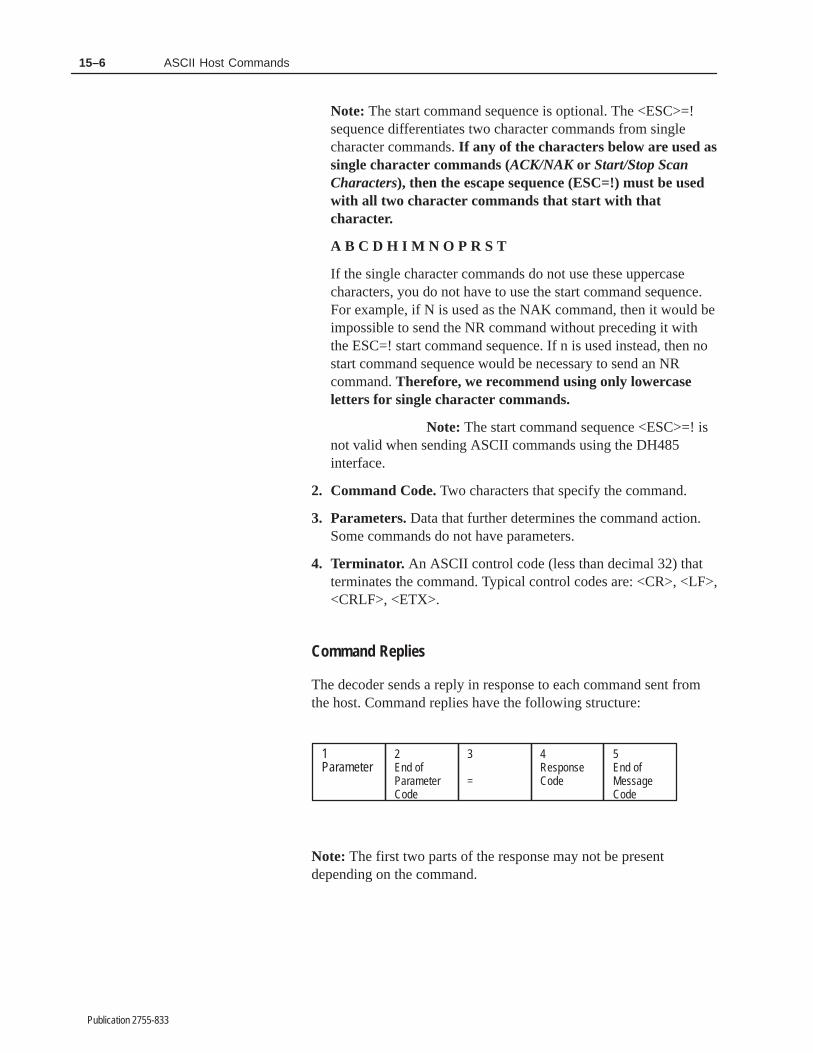
15–6 ASCII Host Commands
Publication 2755-833
Note: The start command sequence is optional. The <ESC>=!sequence differentiates two character commands from singlecharacter commands. If any of the characters below are used assingle character commands (ACK/NAK or Start/Stop ScanCharacters), then the escape sequence (ESC=!) must be usedwith all two character commands that start with thatcharacter.
A B C D H I M N O P R S T
If the single character commands do not use these uppercasecharacters, you do not have to use the start command sequence.For example, if N is used as the NAK command, then it would beimpossible to send the NR command without preceding it withthe ESC=! start command sequence. If n is used instead, then nostart command sequence would be necessary to send an NRcommand. Therefore, we recommend using only lowercaseletters for single character commands.
Note: The start command sequence <ESC>=! isnot valid when sending ASCII commands using the DH485interface.
2. Command Code. Two characters that specify the command.
3. Parameters. Data that further determines the command action.Some commands do not have parameters.
4. Terminator. An ASCII control code (less than decimal 32) thatterminates the command. Typical control codes are: <CR>, <LF>,<CRLF>, <ETX>.
Command Replies
The decoder sends a reply in response to each command sent fromthe host. Command replies have the following structure:
1Parameter
2End ofParameterCode
3
=
4ResponseCode
5End ofMessageCode
Note: The first two parts of the response may not be presentdepending on the command.

15–7ASCII Host Commands
Publication 2755-833
1. Parameters. Contains data requested by the commandparameters. Some commands do not return any parameters.
2. End of Parameter Code. Delimiter that indicates the end of theparameter list. This code is the same as the End of Message Code.
3. = Response delimiter.
4. Response Code. Indicates the status of the processed command.The table below lists the response codes and what they mean.
Response Codes and Descriptions
Response Description
00 Command complete (normal termination).
01 Valid and successful command. Applies only to TM command.
02 Display buffer is full. Applies only to TM command.
11 Valid command but format is invalid.
50 Unknown command.
97 Reset to new configuration received.
98 Reset to default configuration received.
5. End of Message Code. Indicates the end of the message. Typicalend of message control codes are CR, CRLF, LF, ETX, or None.
All examples in this chapter use <end> to represent the end ofmessage control code.
The End Message configuration parameter defines the end ofmessage control code. Refer to the Host Message Format screendescribed elsewhere in this manual for additional details.

15–8 ASCII Host Commands
Publication 2755-833
CT - Configure Bar Code Symbology and Supplements
Command Format: CTfccs
Function: Enables or disables the decoding of a specificbar code symbology and supplements.
Parameters: fccs
CommandParameter Parameter Function Valid Values
f Enable a bar codesymbology?
1=Yes0=No
cc Specifies a bar codesymbology.①
01=Code 3902=Interleaved 2-of-503=Codabar04=UPC-A05=UPC-E06=EAN-807=EAN-1308=Code 128
sSpecifies supple-ments for a bar codesymbology. ➁
0=None1=2 character supplement2=5 character supplement3=2 or 5 character supplement4= Auto (None, 2 or 5 character supplement)
① See the CP command for Pharma-Code configuration.
➁ Supplements are valid for UPC–A, UPC–E, EAN–8, EAN 13. For othersymbologies, select 0=None or omit the “s” parameter.
Response: = rr <end>
rr = response code<end> = end of message control code
Example:
Command: CT1041
Parameters: 1041
CommandParameter Parameter Functions Values
f Enable bar code symbology? 1= Yes
cc Select bar code symbology. 04= UPC-A
s Enable supplements forselected symbology.
1= 2 charactersupplement.
00 = command completeresponse code
CR = � � �� ������ �� �������� ��� ������ �����

15–9ASCII Host Commands
Publication 2755-833
SL - Configure Specific Length for Bar Code Symbology
Command Format: SLccssttuuvvwwxxyyzz
Function: Configures specific lengths for Code 39,Interleaved 2-of-5, Codabar, and Code 128symbologies.
Parameters: ccssttuuvvwwxxyyzz
CommandParameter
ParameterFunction Valid Values
cc Bar codesymbology
01= Code 3902= Interleaved 2-of-503= Codabar08= Code 128
ss 1st specific length 00 through 64 ①
tt 2nd specific length 00 through 64 ①
uu 3rd specific length 00 through 64 ①
vv 4th specific length 00 through 64 ①
ww 5th specific length 00 through 64 ①
xx 6th specific length 00 through 64 ①
yy 7th specific length 00 through 64 ①
zz 8th specific length 00 through 64 ①
① A value of 00 in the leftmost field indicates a variable length up to64. A nonzero value in the left of each field indicates a specificlength. The specific length for Interleaved 2-of-5 must be an evennumber. A two character Interleaved 2-of-5 symbol requires alength of 2.
Response: = rr <end>
rr = response code<end>= end of message control code
for Carriage Return.

15–10 ASCII Host Commands
Publication 2755-833
SL - Configure Specific Length for Bar Code Symbology(continued)
Example:
Command: SL021416000000000000
Parameters: 021416000000000000
CommandParameter
ParameterFunction Values
cc Bar code type 02= Interleaved 2-of-5
ss 1st specific length 14①
tt 2nd specific length 16①
uu 3rd specific length 00①
vv 4th specific length 00①
ww 5th specific length 00①
xx 6th specific length 00①
yy 7th specific length 00①
zz 8th specific length 00①
① Only Interleaved 2-of-5 symbols with 14 and 16 characters will bedecoded.
Response: = 00CRLF
00 = command completeresponse code
CRLF = end of message control codefor Carriage Return andLine Feed.

15–11ASCII Host Commands
Publication 2755-833
CC - Configure Code 39, I 2-of-5, Codabar Check Characters
Command Format: CCabcdef
Function: Enables or disables bar code check characters.
Parameters: abcdef
a through f are Yes (1) and No (0) responses tothe following parameters (in sequence shown):
CommandParameters Parameter Function Valid Values
a Code 39 check character? 1=Yes, 0=No
b Send Code 39 check character? 1=Yes, 0=No
c I 2-of-5 check character? 1=Yes, 0=No
d Send I 2-of-5 check character? 1=Yes, 0=No
e Codabar check character? 1=Yes, 0=No
f Send Codabar check character? 1=Yes, 0=No
Response: = rr <end>
rr = response code<end> = end of message control
code
Example:
Command: CC111100
Parameters: 111100
CommandParameters Parameter Function Values
a Code 39 check character? 1=Yes
b Send Code 39 check character? 1=Yes
c I 2-of-5 check character? 1=Yes
d Send I 2-of-5 check character? 1=Yes
e Codabar check character? 0=No
f Send Codabar check character? 0=No
Response: = 00CR
00 = command completeresponse code
CR = end of message control codefor Carriage Return.

15–12 ASCII Host Commands
Publication 2755-833
CG - Configure Interleaved 2-of-5 Guard Bar
Command Format: CGa
Function: Enables verification of guard bars on Interleaved2-of-5 symbols.
Parameters: a
CommandParameters Parameter Function Valid Values
a Enable verification of guard baron I 2/5 symbols
1=Yes, 0=No
Response: = rr <end>
rr = response code <end>= end of message control code
Example:
Command: CG1
Parameters: 1
CommandParameters Parameter Function Values
a Enable verification of guard baron I 2/5 symbols
1=Yes
Response: = 00CR
00 = command completeresponse code
CR= end of message control codefor Carriage Return.

15–13ASCII Host Commands
Publication 2755-833
CQ - Configure Quiet Zone
Command Format: CQaa
Function: Configures the General Quiet Zone Ratio.
Parameters: aa
CommandParameters Parameter Function Valid Values
aa The Quiet Zone Ratio 00 = Defaults04 – 10
Response: = rr <end>
rr = response code<end>= end of message control code
Example:
Command: CQ07
Parameters: 07
CommandParameters Parameter Function Values
aa Set Quiet Zone Ratio to 7 07
Response: = 00CR
00 = command completeresponse code
CR = end of message control codefor Carriage Return.
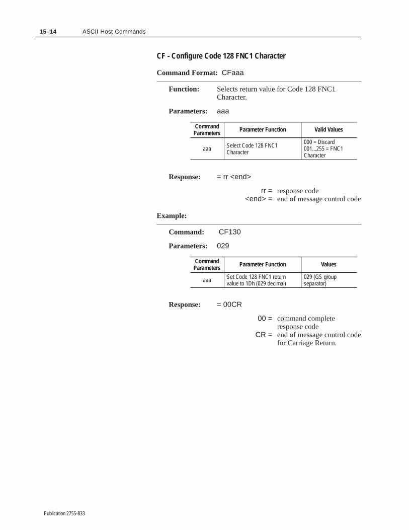
15–14 ASCII Host Commands
Publication 2755-833
CF - Configure Code 128 FNC1 Character
Command Format: CFaaa
Function: Selects return value for Code 128 FNC1Character.
Parameters: aaa
CommandParameters Parameter Function Valid Values
aaa Select Code 128 FNC1Character
000 = Discard001...255 = FNC1Character
Response: = rr <end>
rr = response code<end> = end of message control code
Example:
Command: CF130
Parameters: 029
CommandParameters Parameter Function Values
aaa Set Code 128 FNC1 returnvalue to 1Dh (029 decimal)
029 (GS groupseparator)
Response: = 00CR
00 = command completeresponse code
CR = end of message control codefor Carriage Return.
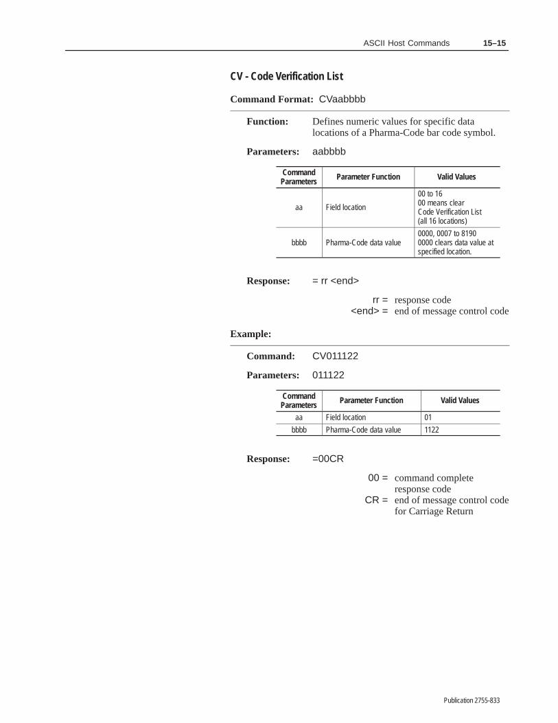
15–15ASCII Host Commands
Publication 2755-833
CV - Code Verification List
Command Format: CVaabbbb
Function: Defines numeric values for specific datalocations of a Pharma-Code bar code symbol.
Parameters: aabbbb
CommandParameters Parameter Function Valid Values
aa Field location
00 to 1600 means clear Code Verification List(all 16 locations)
bbbb Pharma-Code data value0000, 0007 to 81900000 clears data value atspecified location.
Response: = rr <end>
rr = response code<end> = end of message control code
Example:
Command: CV011122
Parameters: 011122
CommandParameters Parameter Function Valid Values
aa Field location 01
bbbb Pharma-Code data value 1122
Response: =00CR
00 = command completeresponse code
CR = end of message control codefor Carriage Return

15–16 ASCII Host Commands
Publication 2755-833
CP - Configure Pharma-Code Symbology
Command Format: CPabccddeefgg
Function: Enables the Pharma-Code symbology andconfigures parameters of the symbology.
Parameters: abccddeefgg
CommandParameters Parameter Function Valid Values
a Enable symbology 0= No1= Yes
b Decode direction
0= Forward1= Reverse2= Forward Scanner A Reverse Scanner B①
3= Reverse Scanner A Forward Scanner B①
cc Quiet zone ratio 04 to 10
dd Space tolerance 00=Ignore05 to 40
ee Bar tolerance 00=Ignore05 to 40
f Wide to narrow bar ratio 0=midrange2 to 4
gg Minimum number of bars 03 to 12
① Applies only to Dual-Head Decoder.
Response: = rr <end>
rr = response code<end>= end of message code

15–17ASCII Host Commands
Publication 2755-833
CP - Configure Pharma-Code Symbology (continued)
Example:
Command: CP10040000005
Parameters: 10040000005
CommandParameters Parameter Function Valid Values
a Enable symbology 1= Yes
b Decode direction 0= Forward
cc Quiet zone ratio 04
dd Space tolerance 00=Ignore
ee Bar tolerance 00=Ignore
f Wide to narrow bar ratio 0=midrange
gg Minimum number of bars 05
Response: =00CR
00 = command completeresponse code
CR = end of message control codefor Carriage Return

15–18 ASCII Host Commands
Publication 2755-833
SC - Configure Scanner A Control
Command Format: SCldcsprrrrttttm
Function: Specifies the operating parameters for ScannerA or Scanners A and B in coordinated mode.
Parameters: ldcsprrrrtttttm
CommandParameters Parameter Function Valid Values
l Laser-light0= On1= Triggered2= Off
d Trigger mode
0= Package Detect1= Host2= Internal Timer3= Continuous4= Continuous/unique
c Capture count. 0, 1 through 8(0= Verify)
s Bar code symbols per scan 0 through 60= ANY (1,2,3,4,5,6)
p Bar code symbols perpackage
1 -9, A-G(where A=10,...G=16)
rrrr No-read timer value(in milliseconds)
0000, 0010 - 9999 (in milliseconds)0000 disables timeout
tttt Inter–scan timer value(in milliseconds)
0000, 0010 - 9999 (in milliseconds)0000 disables timeout
m Match complete count 1 -9, A-G (where A=10,...G=16)
Important: See Chapter 6 for a description ofthe Scanner Control parameters.
Response: = rr <end>
rr = response code<end> = end of message control code

15–19ASCII Host Commands
Publication 2755-833
SC - Configure Scanner A Control (continued)
Example:
Command: SC01211005500001
Parameters: 01211005500001
CommandParameters Parameter Function Values
l Laser-light 0=Continuous scanning
d Decode trigger mode 1= Host
c Capture count 2
s Bar code symbols per scan 1
p Bar code symbols perpackage
1
rrrr No-read timer value(in milliseconds)
0055= 55 millisecondtimer value
tttt Inter–scan timer value(in milliseconds)
0000= Disablesinter-scan timer
m Match complete count 1
Response: = 00CR
00 = command completeresponse code
CR = end of message control codefor Carriage Return

15–20 ASCII Host Commands
Publication 2755-833
PB - Configure Scanner B Control
Command Format: PBabtttt
Function: Configures Scanner B to operate in coordinatedor independent mode. This command alsodefines the operating parameters for Scanner Bwhen the scanning mode is set to independent.
NOTE: This command is valid only for dualhead decoders.
Parameters: abtttt
CommandParameters Parameter Function Valid Values
a Scanning mode of scanner B
0= Coordinated 11= Independent Package Detect2= Independent Host Triggered3= Coordinated 2
b Reserved Ignored①
tttt Trigger timeout for scanner B(in milliseconds)
0000, 0010 - 9999 (in milliseconds)0000 disables timeout
① Decoder ignores character but it must be supplied to maintain compati-bility with previous decoders.
Important: See Chapter 7 for a description ofthe Scanner Control parameters.
Response: = rr <end>
rr = response code<end> = end of message control code
Example:
Command: PB110100
Parameters: 110100
CommandParameters Parameter Function Values
a Scanning mode of scanner B 1= IndependentPackage Detect
b Ignored 1 (Ignored)
tttt Trigger timeout for scanner B(in milliseconds)
0100= 100 milliseconds
Response: = 00CR
00 = command completeresponse code
CR = end of message control codefor Carriage Return

15–21ASCII Host Commands
Publication 2755-833
IF - Configure Scanner A Package Detect Filter and Sense
Command Format: IFf
Function: Enables or disables the 15 ms input filter anddetermines the sense of the package detect signalfor Scanner A.
Parameters: f = disable or enable filter/select sense.
CommandParameter
ParameterFunction Valid Values
f Enable or disablefilter/select sense
0=disable filter,LO when package is present
1=enable filter,LO when package is present
2=disable filter,HI when package is present
3=enable filter,HI when package is present
Response: = rr <end>
rr = response code<end> = end of message control code
Example:
Command: IF1
Parameters: 1
CommandParameter
ParameterFunction Value
f Enable or disablefilter/select sense
1=enable filter,LO when package is present
Response: = 00CR
00 = command completeresponse code
CR = end of message control codefor Carriage Return

15–22 ASCII Host Commands
Publication 2755-833
BF - Configure Scanner B Package Detect Filter and Sense
Command Format: BFf
Function: Enables or disables the 15 ms input filter anddetermines the sense of the package detect signalfor Scanner B.
NOTE: This command is valid only for dualhead decoders.
Parameters: f = disable or enable filter/select sense.
CommandParameter
ParameterFunction Valid Values
f Enable or disablefilter/select sense
0=disable filter,LO when package is present
1=enable filter,LO when package is present
2=disable filter,HI when package is present
3=enable filter,HI when package is present
Response: = rr <end>
rr = response code<end> = end of message control code
Example:
Command: BF1
Parameters: 1
CommandParameter
ParameterFunction Value
f Enable or disablefilter/select sense
1=enable filter,LO when package is present
Response: = 00CR
00 = command completeresponse code
CR = end of message control codefor Carriage Return

15–23ASCII Host Commands
Publication 2755-833
BL - Configure Scanner B Laser Mode
Command Format: BLa
Function: Configures the laser light for scanner B.
NOTE: This command is valid only for dualhead decoders.
Parameters: a
CommandParameters Parameter Function Valid Values
a Scanner B laser light0= On1= Triggered2= Off
Response: = rr <end>
rr = response code<end> = end of message control code
Example:
Command: BL1
Parameters: 1
CommandParameters Parameter Function Values
a Scanner B laser light 1=Triggered
Response: = 00CR
00 = command completeresponse code
CR = end of message control codefor Carriage Return.

15–24 ASCII Host Commands
Publication 2755-833
SW - Write Scanner Source to Match Code Table
Command Format: SWab
Function: Configures the source of an event.
Parameters: ab
CommandParameters Parameter Function Valid Values
a Match code table entry number 1 through 8
b Source of event
1=Scanner A2=Scanner B①
3=A|B①
4=Illegal5=A–B①
① Applies only to Dual-Head Decoder.
Response: = rr <end>
rr = response code<end> = end of message control code
Example:
Command: SW11
Parameters: 1
CommandParameters Parameter Function Values
a Match code table entry number 1
b Source of event 1=Scanner A
Response: = 00CR
00 = command completeresponse code
CR = end of message control codefor Carriage Return.

15–25ASCII Host Commands
Publication 2755-833
AB - Auto-load Begin
Command Format: AB
Function: Resets autoloads. Once received, the decoderloads match code table positions set to autoloadwith decoded bar code data until it receives anAE (Autoload End command. Equivalent tomanual autoload input.
Response: = rr <end>
rr = response code<end>= end of message control
code
Example:
Command: AB
Response: = 00CR
00 = command completeresponse code
CR = end of message control codefor Carriage Return.
AE - Autoload End
Command Format: AE
Function: Stops loading data into position set to autoload.This command follows an AB (Autoload Begin)command. Equivalent to releasing a manualautoload input.
Response: = rr <end>
rr = response code<end> = end of message control code
Example:
Command: AE
Response: = 00CR
00 = command completeresponse code
CR = end of message control codefor Carriage Return.
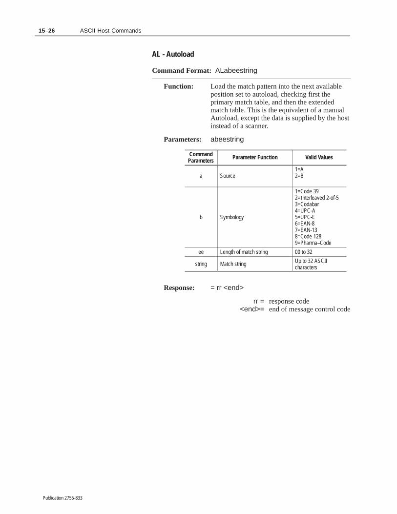
15–26 ASCII Host Commands
Publication 2755-833
AL - Autoload
Command Format: ALabeestring
Function: Load the match pattern into the next availableposition set to autoload, checking first theprimary match table, and then the extendedmatch table. This is the equivalent of a manualAutoload, except the data is supplied by the hostinstead of a scanner.
Parameters: abeestring
CommandParameters Parameter Function Valid Values
a Source1=A2=B
b Symbology
1=Code 392=Interleaved 2-of-53=Codabar4=UPC-A5=UPC-E6=EAN-87=EAN-138=Code 1289=Pharma–Code
ee Length of match string 00 to 32
string Match string Up to 32 ASCIIcharacters
Response: = rr <end>
rr = response code<end>= end of message control code

15–27ASCII Host Commands
Publication 2755-833
AL - Autoload (continued)
Example:
Command: AL
Parameters: 1110ABCDE12345
CommandParameters Parameter Function Valid Values
a Source 1=A
b Symbology 1=Code 39
ee Length of match string 10 Characters
String Match string ABCDE12345
Response: = 00CR
00 = command completeresponse code
CR = end of message control codefor Carriage Return.

15–28 ASCII Host Commands
Publication 2755-833
OS - Set Output Normally Open/Closed
Command Format: OSnf
Function: Sets the state of a discrete output to normallyopen or normally closed.
Parameters: nf
CommandParameters Parameter Function Valid Values
n Discrete output number 1 through 8
f Switch operation normallyopen or normally closed
0= Normally Open1= Normally Closed
Response: = rr <end>
rr = response code<end>= end of message control code
Example:
Command: OS20
Parameters: 20
CommandParameters Parameter Function Values
n Discrete output number 2
f Switch operation normallyopen or normally closed
0= Normally Open
Response: =00CR
00 = command completeresponse code
CR = end of message control codefor Carriage Return

15–29ASCII Host Commands
Publication 2755-833
OC - Set Output Condition and Output Duration
Command Format: OCnctttt
Function: Sets the condition that will activate an outputand the length of time (in milliseconds) theoutput is activated.
Parameters: nctttt
CommandParameters Parameter Function Valid Values
n Output number 1 through 8
c Condition activates output
0= None1= Read (Package)2= No-Read (Package)3= Match Complete4= Match Entry5= Read and No-Match6= No-Read orNo–Match7= Auto Load8= Auto Load (Input)①9= Host buffer fullA= Host buffer overflow
tttt Time (in milliseconds) thatoutput is activated.
0000, 0010 to 9999 (milliseconds)0000 disables condition
① The AutoLoad (Input) function applies only to output 8.
Response: = rr <end>
rr = response code <end> = end of message control code

15–30 ASCII Host Commands
Publication 2755-833
OC - Set Output Condition and Output Duration (continued)
Example:
Command: OC510110
Parameters: 510110
CommandParameters Parameter Function Values
n Output number 5
c Condition that activates output 1= Read (Package)
tttt Time (in milliseconds) thatoutput is activated.
0110= 110 milliseconds
Response: = 00CR
00 = command completeresponse code
CR = end of message control codefor Carriage Return

15–31ASCII Host Commands
Publication 2755-833
OH - Hold Output Open/Closed
Command Format: OHnfftttt
Function: Allows the host to control the discrete outputs(regardless of their ”normal” state) for a setduration.➀ When the duration expires, the outputreverts to its previous state.
Note: If a normally open output is held open (ora normally closed output is held closed), thestate of the output will not change.
!ATTENTION: An output held open or closed willreestablish itself after a power loss (all other conditionswill be deactivated if power is lost). A Restartcommand will deactivate a held output.
Parameters: nfftttt
CommandParameters Parameter Function Valid Values
n Discrete output number 1 through 8
ff Hold switch operation in openor closed state?
00= Hold Open➀
11= Hold Close
tttt
Time (in milliseconds) thatoutput remains in held state.When the time expires, theoutput returns to its previousstate.
0000, 0010 to 9999 (milliseconds)
0000 holds output instate until changed.
Response: = rr <end>
rr = response code<end> = end of message control code
➀ A duration of 0000 holds the specified output in the programmed state until it is changed withhost command or via the AUX terminal configuration screens. The condition field on the AUXwill display Open or Closed.

15–32 ASCII Host Commands
Publication 2755-833
OH - Hold Output Open/Closed (continued)
Example:
Command: OH2001000
Parameters: 2001000
CommandParameters Parameter Function Values
n Discrete output number 2
ff State of discrete output 00= Hold Open
tttt Time (in milliseconds) thatoutput remains held open.
1000 milliseconds
Response: = 00CR
00 = command completeresponse code
CR = end of message control codefor Carriage Return

15–33ASCII Host Commands
Publication 2755-833
MR - Read Primary Match Code Table Entry
Command Format: MRn
Function: Read match code configuration for table entry1 – 8.
Parameters: n = match code table entry number 1 through 8.
CommandParameters Parameter Function Valid Values
n Match code table entry number 1 through 8
f RESERVED 1①
cc Bar code symbology
01=Code 3902=Interleaved 2 of 503=Codabar04=UPC-A05=UPC-E06=EAN-807=EAN-1308=Code 12809=Pharma–Code16=Any
ll Length of match string 00 to 32
string Match string up to 32 characters
① This value is always returned as 1.
Response: nfccllstring<end> = rr <end>
<end> = end of message control coderr = response code
<end> = end of message control codeExample:
Command: MR3
Parameters: 3 = match code entry #3
CommandParameters Parameter Function Values
n Match code table entry number 3
f RESERVED 1①
cc Bar code symbology 01=Code 39
ll Length of match string 05
string Match string 12345
① This value is always returned as 1.
Response: 31010512345CR = 00CR
CR = end of message control code00 = command complete
response codeCR = end of message control code

15–34 ASCII Host Commands
Publication 2755-833
MW - Write Primary Match Code Table Entry
Command Format: MWnfccllstring
Function: Configure a match code for table entry 1 – 8.
Parameters: nfccllstring
CommandParameters Parameter Function Valid Values
n Match code table entry number 1 through 8
f RESERVED Ignored①
cc Bar code symbology
01=Code 3902=Interleaved 2 of 503=Codabar04=UPC-A05=UPC-E06=EAN-807=EAN-1308=Code 12809=Pharma–Code16=Any
ll Length of match code string 00 to 32②
string Match code characters up to 32 characters③
① Decoder ignores character but it must be supplied to maintain compati-bility with previous decoders.
② A zero length string disables a match code entry. A nonzero lengthstring enables the match code entry.
③ The string must be as long as the specified string length (ll).
Response: = rr <end>
rr= response code<end> = end of message control code

15–35ASCII Host Commands
Publication 2755-833
MW - Write Primary Match Code Table Entry (continued)
Example:
Command: MW4102041289
Parameters: 4102041289
CommandParameters Parameter Function Values
n Match code table entry number 4
f RESERVED 1
cc Bar code symbology 02=Interleaved 2 of 5
ll Length of match string 04
string Match string 1289
Response: = 00LF
00 = command completeresponse code
LF = end of message control codefor Line Feed
CM - Clear Primary Output Counters
Command Format: CMn
Function: Clears the selected output counter to 0.
Parameters: n = output counter number 1 through 8
Response: = rr <end>
rr = response code<end > = end of message control code
Example:
Command: CM3
Parameters: 3 = output counter #3.
Response: = 00CR
00= command completeresponse code
CR = end of message control codefor Carriage Return

15–36 ASCII Host Commands
Publication 2755-833
CO - Clear All Primary Output Counters
Command Format: CO
Function: Clears the Primary Counters to zero.
Parameters: None
Response: = rr <end>
rr = response code<end>= end of message control
codeExample:
Command: CO
Response: = 00CR
00 = command completeresponse code
CR = end of message control codefor Carriage Return
CA - Clear Extended Match Counters
Command Format: CA
Function: Clears the value of the extended counts to zero.
Parameters: None
Response: = rr <end>
rr = response code<end> = end of message control code
Example:
Command: CA
Response: = 00CR
00 = command completeresponse code
CR = end of message control codefor Carriage Return

15–37ASCII Host Commands
Publication 2755-833
SE - Set Extended Match Counters
Command Format: SEnnnmmmmmm
Function: Sets the value of extended count number nnn tommmmmm.
Parameters: nnnmmmmmm
CommandParameters Parameter Function Valid Values
nnn The number of the Extendedmatch count
001 to 128000 = All
mmmmmm The value of the count 000000 to 999999
Response: = rr <end>
rr = response code<end> = end of message control code
Example:
Command: SC012000036
Parameters: 012
CommandParameters Parameter Function Values
nnn The number of the Extendedmatch count.
012
mmmmmm The value of the count 000036
Response: = 00CR
00 = command completeresponse code
CR = end of message control codefor Carriage Return.

15–38 ASCII Host Commands
Publication 2755-833
RC - Read Extended Match Counters
Command Format: RCnnn
Function: Reads the value of Extended count number nnn.
Parameters: nnn
CommandParameters Parameter Function Valid Values
nnn The number of the Extendedmatch count
001 to 128
Response: = mmmmmm <end>
mmmmmm = count value<end> = end of message control code
Example:
Command: RC012
Parameters: 012
CommandParameters Parameter Function Values
nnn The number of the Extendedmatch count.
012
Response: = 000036CR
000036 = value of counter 12CR = end of message control code
for Carriage Return.

15–39ASCII Host Commands
Publication 2755-833
SM - Set Extended Match Data
Command Format: SMnnnasccmmmmmmddddddddllstring
Function: Sets the value of the Extended data number nnn.
Parameters: nnnasccmmmmmmddddddddllstring
CommandParameters Parameter Function Valid Values
nnn The number of the Extendedmatch count
000 to 128
a Mode
A=Auto-loadM=Match EntryD=DisabledL=Lot
s Source
1=Scanner A2=Scanner B3=A|B4=Illegal5=A–B
cc symbology
01=Code 3902=Interleaved 2-of-503=Codabar04=UPC-A05=UPC-E06=EAN-807=EAN-1308=Code 12809=Pharma–Code16=Any
mmmmmm The value of the count 000000 to 999999
dddddddd Loading (8) 0 to 9, or X
ll Length of match string 00 to 32
string Match string up to 32 characters
Response: = rr <end>
rr = response code<end>= end of message control code

15–40 ASCII Host Commands
Publication 2755-833
SM - Set Extended Match Data (continued)
Example:
Command: SM002M30100000010000000041289
Parameters: 002 M 3 01 000000 10000000 04 1289
CommandParameters Parameter Function Valid Values
nnn The number of the Extendedmatch count
002
a Mode M = Match Entry
s Source 3=A|B
cc Symbology 01=Code 39
mmmmmm The value of the count 000000
dddddddd Loading (8) 10000000
ll Length of match string 04
string Match string 1289
Response: = 00CR
00 = command completeresponse code
CR = end of message control codefor Carriage Return.

15–41ASCII Host Commands
Publication 2755-833
RP - Read All Extended Match Data
Command Format: RP
Function: Reads the value of all Extended data.
Parameters: None
ResponseParameters Parameter Function Valid Values
nnn The number of the Extendedmatch counts
001 to 128
a Mode
A=Auto-loadM=Match EntryD=DisabledL=Lot
ss Source
01=Scanner A02=Scanner B03=A|B04=A–B
cc Symbology
01=Code 3902=Interleaved 2-of-503=Codabar04=UPC-A05=UPC-E06=EAN-807=EAN-1308=Code 12809=Pharma–Code16=Any
mmmmmm The value of the count 000000 to 999999
ll Length of match string 00 to 32
string Match string up to 32 characters
Response: 001assccmmmmmmmmllstring<end>.....128assccmmmmmmmmllstring<end>=rr<end>
rr = response code<end>= end of message control code

15–42 ASCII Host Commands
Publication 2755-833
RP - Read All Extended Match Data (continued)
Example:
Command: RP
Response: 001 M 03 01 001289 04 1289 CR 002 ......128 M 03 01 001289 04 1289 CR=00CR
CommandParameters Parameter Function Values
nnn The number of the Extendedmatch counts
064
a Mode M = Match Entry
s Source 03=A|B
cc symbology 01=Code 39
mmmmmm The value of the count 001289
ll Length of match string 04
string Match string 1289
a Mode M = Match Entry
s Source 3=A|B
cc Symbology 01=Code 39
mmmmmm The value of the count 000222
ll Length of match string 04
string Match string 6247
CR = delimiter and/or end ofmessage control code forCarriage Return
00 = command completeresponse code
CR = end of message control codefor Carriage Return.

15–43ASCII Host Commands
Publication 2755-833
RA - Read All Extended Counters
Command Format: RA
Function: Reads all Extended counts.
Parameters: None
Response: nnnmmmmmm<end>......nnnmmmmmm<end>= rr <end>
ResponseParameters Parameter Function Valid Values
nnn The number of the Extendedmatch count
001
mmmmmm Value of count 000000 to 999999
nnn The number of the Extendedmatch count
002
mmmmmm Value of count 000000 to 999999
...
nnn The number of the Extendedmatch count
128
mmmmmm Value of count 000000 to 999999
rr= response code<end> = end of message control code

15–44 ASCII Host Commands
Publication 2755-833
RA - Read All Extended Counters (continued)
Example:
Command: RA
Parameters: None
Response: 001000012CR002000122...... 128000012CR=00CR
ResponseParameters Parameter Function Values
nnn The number of the Extendedmatch count
001
mmmmmm Value of count 000012
nnn The number of the Extendedmatch count
002
mmmmmm Value of count 000122
...
nnn The number of the Extendedmatch count
128
mmmmmm Value of count 000000
Response: = 00CR
00 = command completeresponse code
CR = end of message controlcode for Carriage Return.

15–45ASCII Host Commands
Publication 2755-833
CS - Disable Extended Match Code Set
Command Format: CSnnnnnnnn
Function: Disables a group of Extended Match Codes
Parameters: nnnnnnnn
CommandParameters Parameter Function Valid Values
nnnnnnnn
Allows the 128 Extended MatchCodes to be treated as eightsets of sixteen each. Each setcan be individually marked.
00000000 = AllDisabled through 11111111=All enabled
Response: = rr <end>
rr = response code<end> = end of message control code
Example:
Command: CS01100011
Parameters: 01100011
CommandParameters Parameter Function Values
nnnnnnnn Enables positions 17–32, 33–48,97–112, and 113–128 01100011
Response: = 00CR
00 = command completeresponse code
CR = end of message control codefor Carriage Return.

15–46 ASCII Host Commands
Publication 2755-833
RS - Read Extended Match Set Status
Command Format: RS
Function: Reads the status of the extended match sets.
Parameters: none
Response: nnnnnnnn = rr <end>
rr = response code<end> = end of message control code
Example:
Command: RS
Response: 10010001 = 00CR
10010001 = Sets 1, 4, and 8 enabled; allothers disabled.
00 = command completeresponse code
CR = end of message control codefor Carriage Return.

15–47ASCII Host Commands
Publication 2755-833
DF - Enable Data Display on AUX Terminal and LCD
Command Format: DFab
Function: Enables the AUX terminal and/or the LCDDisplay to receive and display bar code data.
Note: Before data will display at the AUXterminal, you must set the AUX port to manualdata entry mode (as described in Chapter 13).
Parameters: ab
CommandParameter
ParameterFunction Valid Values
aEnable device todisplay formattedbar code data.
0= None1= AUX terminal and LCD Display2= AUX terminal only3= LCD Only
b Specify format ofbar code data.
0= Unformatted1= Host format
Response: = rr <end>
rr = response code <end> = end of message control code
Example:
Command: DF11
Parameters: 11
CommandParameter
ParameterFunction Values
aEnable device todisplay formattedbar code data.
1= AUX terminal and LCD Display
b Specify format ofbar code data.
1= Host format
Response: = 00LF
00 = command completeresponse code
LF = end of message control codefor Line Feed

15–48 ASCII Host Commands
Publication 2755-833
DP - Configure Data Display Positions for AUX Terminal and LCD
Command Format: DPdpp
Function: Enables the display of specific data items on theLCD and/or AUX port terminal starting at aspecific character position.
Note: Before data will display at the AUXterminal, you must set the AUX port to manualdata entry mode (as described in Chapter 13).
Parameters: dpp
CommandParameter
ParameterFunction Valid Values
d Data item selector
A= Bar Code Data B= Decoder PerformanceC= Package CounterD= No-Read Counter1= Primary Counter 12= Primary Counter 23= Primary Counter 34= Primary Counter 45= Primary Counter 56= Primary Counter 67= Primary Counter 78= Primary Counter 8
pp Character position 00, 01 - 8000= Disable
Response: = rr <end>
rr= response code<end>= end of message control code
Example:
Command: DPA01
Parameters: A01
CommandParameter
ParameterFunction Values
d Data item selector A= Bar Code Data
pp Character position 01
Response: = 00LF
00 = command completeresponse code
LF = end of message control codefor Line Feed

15–49ASCII Host Commands
Publication 2755-833
SD - Enable LCD Scrolling
Command Format: SDf
Function: Enables or disables scrolling of the LCD display.
Parameters: f
CommandParameters Parameter Function Values
f Enable Scrolling LCD Display 0= No1= Yes
See Chapter 9 for details on how the LCDDisplay operates when scrolling is enabled ordisabled.
Response: = rr <end>
rr = response code<end> = end of message control code
Example:
Command: SD1
Parameters: 1
CommandParameters Parameter Function Values
f Enable scrolling LCD Display 1= Yes
Response: =00CR
00 = command completeresponse code
CR = end of message control codefor Carriage Return

15–50 ASCII Host Commands
Publication 2755-833
SR - Set Search and Replace Rule for Host Message Fields
Command Format: SRnnmmsccbbffapppllstringllstring
Function: Set parameters for the host message replacementrules.
Parameters: nnmmsccbbffapppllstringllstring
CommandParameters Parameter Function Valid Values
nn The number of the Search andReplace Rule
01 to 16
mm The host message field number 00=All or 01 to 16
s Source
1=Scanner A2=Scanner B3=A|B4=Aux
cc Symbology
01=Code 3902=Interleaved 2-of-503=Codabar04=UPC–A05=UPC–E06=EAN–807=EAN–1308=Code 12809=Pharma–Code16=Any
bb Symbol number 00=All or 01 to 16
ff Minimum field length 00 to 64
a Alignment 0=Right1=Left
ppp Fill character 000 to 255(000= No alignment)
ll Length of search pattern string 00=Empty or 01 to 24
string Search pattern string up to 24 characters
ll Length of replace pattern string 00=Empty or 01 to 24
String Replace pattern string up to 24 characters
Response: = rr <end>
rr = response code<end> = end of message control code

15–51ASCII Host Commands
Publication 2755-833
SR - Set Search and Replace Rule for Host Message Fields(continued)
Example:
Command: SR02013010009004807^S(.*)$02\1
Parameters: 02 01 3 01 00 09 0 048 07 ^S(.*)$ 02 \1
CommandParameters Parameter Function Values
nn The number of the Search andReplace Rule
02
mm The host message field number 01
s Source 3=A|B
cc Symbology 01=Code 39
bb Symbol number 00=All
ff Minimum field length 09
a Alignment 0=Right
ppp Fill character 048=0
ll Length of search pattern string 07
String Search pattern string ^S(.*)$
ll Length of replace pattern string 02
String Replace pattern string \1
Response: = 00CR
00 = command completeresponse code
CR = end of message control codefor Carriage Return.

15–52 ASCII Host Commands
Publication 2755-833
SF - Set No-Read Replacement Strings
Command Format: SFnnllstring
Function: Set the No-Read Replacement Strings.
Parameters: nnllstring
CommandParameters Parameter Function Valid Values
nn The number of the No-ReadReplacement String
01 to 16
ll Length of the No-ReadReplacement String
00=Empty or 01 to 24
String No-Read Replacement String up to 24 characters
Response: = rr <end>
rr = response code<end> = end of message control
code
Example:
Command: SF0207No–Read
Parameters: 02 07 No–Read
CommandParameters Parameter Function Values
nn The number of the No-ReadReplacement String
02
ll Length of the No-ReadReplacement String
07
String No-Read Replacement String No–Read
Response: = 00CR
00 = command completeresponse code
CR = end of message control codefor Carriage Return.

15–53ASCII Host Commands
Publication 2755-833
HC - Configure Host Communications
Command Format: HCaaannnssspppfr
Function: Configures host communication parameters.
Parameters: aaannnssspppfr
CommandParameter Parameter Function Valid Values
aaa ACK (Acknowledge) characterASCII decimal value000 to 254255 = None
nnn NAK character(Negative Acknowledgement)
ASCII decimal value000 to 254255 = None
sss Start scan character AASCII decimal value000 to 254255 = None
ppp Stop scan character AASCII decimal value000 to 254255 = None
f Large buffer enable 1=Yes, 0=No
r Send Message to Host0 = At end of Trigger1= Immediately afterValid Package
Response: = rr <end>
rr = response code <end> = end of message control code

15–54 ASCII Host Commands
Publication 2755-833
HC - Configure Host Communications (continued)
Example:
Command: HC03603703504311
Parameters: 03603703504311
CommandParameter Parameter Function Values
aaa ACK character 036 = $ character
nnn NAK character 039 = & character
sss Start character for Scanner A 035 = # character
ppp Stop character for Scanner A 043 = + character
f Large buffer enable 1=Yes
r Send Message to Host 1=Immediately afterValid Package
Response: = 00CR
00 = command completeresponse code
CR = end of message control codefor Carriage Return
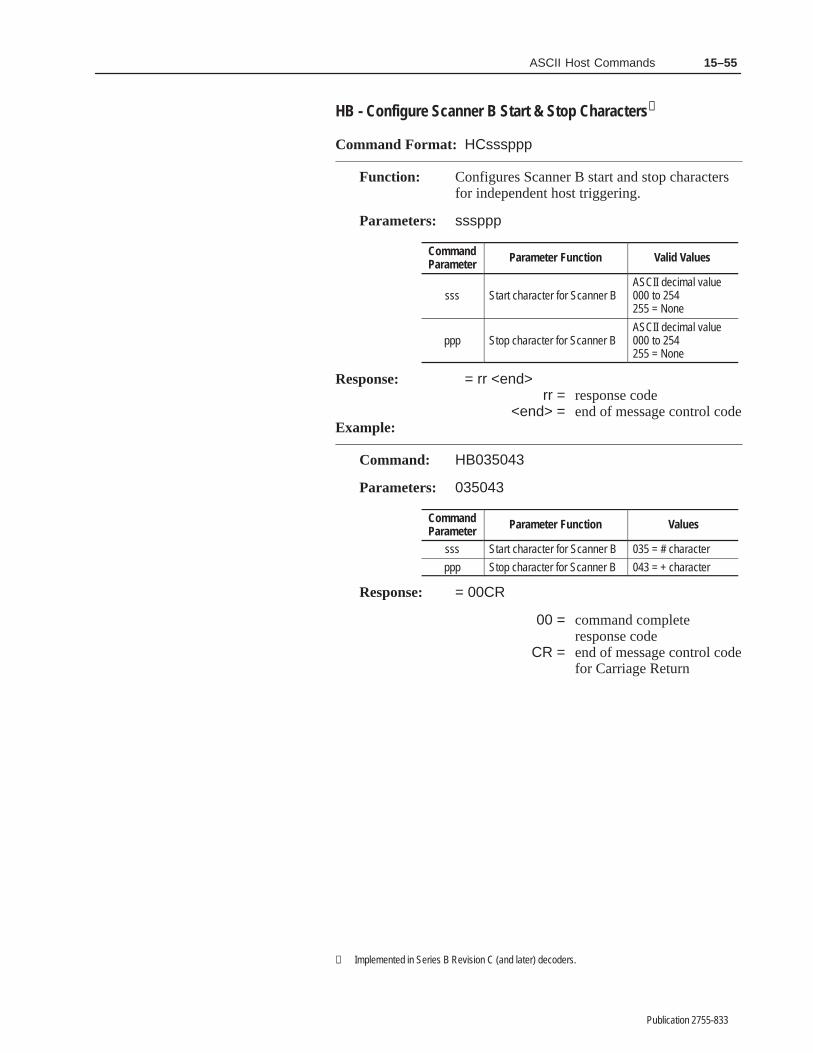
15–55ASCII Host Commands
Publication 2755-833
HB - Configure Scanner B Start & Stop Characters➀
Command Format: HCsssppp
Function: Configures Scanner B start and stop charactersfor independent host triggering.
Parameters: sssppp
CommandParameter Parameter Function Valid Values
sss Start character for Scanner BASCII decimal value000 to 254255 = None
ppp Stop character for Scanner BASCII decimal value000 to 254255 = None
Response: = rr <end> rr = response code
<end> = end of message control codeExample:
Command: HB035043
Parameters: 035043
CommandParameter Parameter Function Values
sss Start character for Scanner B 035 = # character
ppp Stop character for Scanner B 043 = + character
Response: = 00CR
00 = command completeresponse code
CR = end of message control codefor Carriage Return
① Implemented in Series B Revision C (and later) decoders.

15–56 ASCII Host Commands
Publication 2755-833
MF - Configure Host Message Format
Command Format: MFabcdefghhhiiijkl
Function: Configures the format of messages sent to thehost.
Parameters: abcdefghhhiiijkl
a through g are Yes (1) and No (0) responses tothe following parameters (in sequence shown):
CommandParameters Parameter Function Valid Values
a Send bar code data? 1=Yes, 0=No
b Send package count? 1=Yes, 0=No
c Send bar code symbology? 1=Yes, 0=No
d Send source identifier? Ignored①
e Send header message? Ignored①
f Send no-read message? Ignored①
g Expand UPC-E? 1=Yes, 0=No
hhh Label delimiter characterASCII Decimal Value000 to 254255 = None.
iii Start characterASCII Decimal Value000 to 254255 = None.
j End message control character
0 = CRLF1 = CR2 = LF3 = ETX4 = None5 = CR ETX6 = LF ETX7 = CR LF ETX
k Transmission check method
0=None1=LRC2=Checksum-LSB first3=Checksum-MSB first
l Send performance indicator? 1=Yes, 0=No
① These parameters retained for compatibility with existing decoders. Thepresence of each string type indicates that the string should be sent.
Response: = rr <end> rr = response code
<end>= end of message control code

15–57ASCII Host Commands
Publication 2755-833
MF - Configure Host Message Format (continued)
Example:
Command: MF1101110094042100
Parameters: 1101110094042100
CommandParameters Parameter Function Values
a Send bar code data? 1=Yes
b Send package count? 1=Yes
c Send bar code symbology? 0=No
d Send source identifier? Ignored①
e Send header message? Ignored①
f Send no-read message? Ignored①
g Expand UPC-E? 0=No
hhh Label delimiter character 094 = ^ character
iii Start character 042 = * character
j End message control character 1 = CR
k Transmission check method 0 = None
l Send performance indicators? 0 = No
Response: = 00CR
00 = command completeresponse code
CR= end of message controlcode for Carriage Return

15–58 ASCII Host Commands
Publication 2755-833
HF - Set the Number of Fields in Host Message
Command Format: HFnn
Function: Sets the number of fields in the host message.
Parameters: nn
CommandParameter Parameter Function Valid Values
nn Set the number of fields inhost message
00 to 16,00 = All
Response: = rr <end>
rr = response code <end> = end of message control code
Example:
Command: HF02
Parameters: 02
CommandParameter Parameter Function Valid Values
nn Set the number of fields inhost message
02
Response: = 00CR
00= command completeresponse code
CR= end of message controlcode for Carriage Return

15–59ASCII Host Commands
Publication 2755-833
IX - Configure AUX Terminal Source Identifier
Command Format: IXlstring
Function: Defines a source identifier for the AUX portterminal. Source identifiers are included inmessages sent to the host. They identify whetherthe data was scanned (by Scanner A or B) orentered at the AUX terminal.
Note: This command only applies when theAUX port is set for manual data entryoperations.
Parameters: lstring
CommandParameter Parameter Function Valid Values
l Length of source identifier 0 to 4①
String Characters in source identifier Up to 4 characters
① A zero length string will disable the source identifier.
Response: = rr <end>
rr = response code <end> = end of message control code
Example:
Command: IX3AUX
Parameters: AUX
CommandParameter Parameter Function Values
l Length of source identifier 3
String Characters in source identifier AUX
Response: = 00LF
00= command completeresponse code
LF= end of message control codefor Line Feed
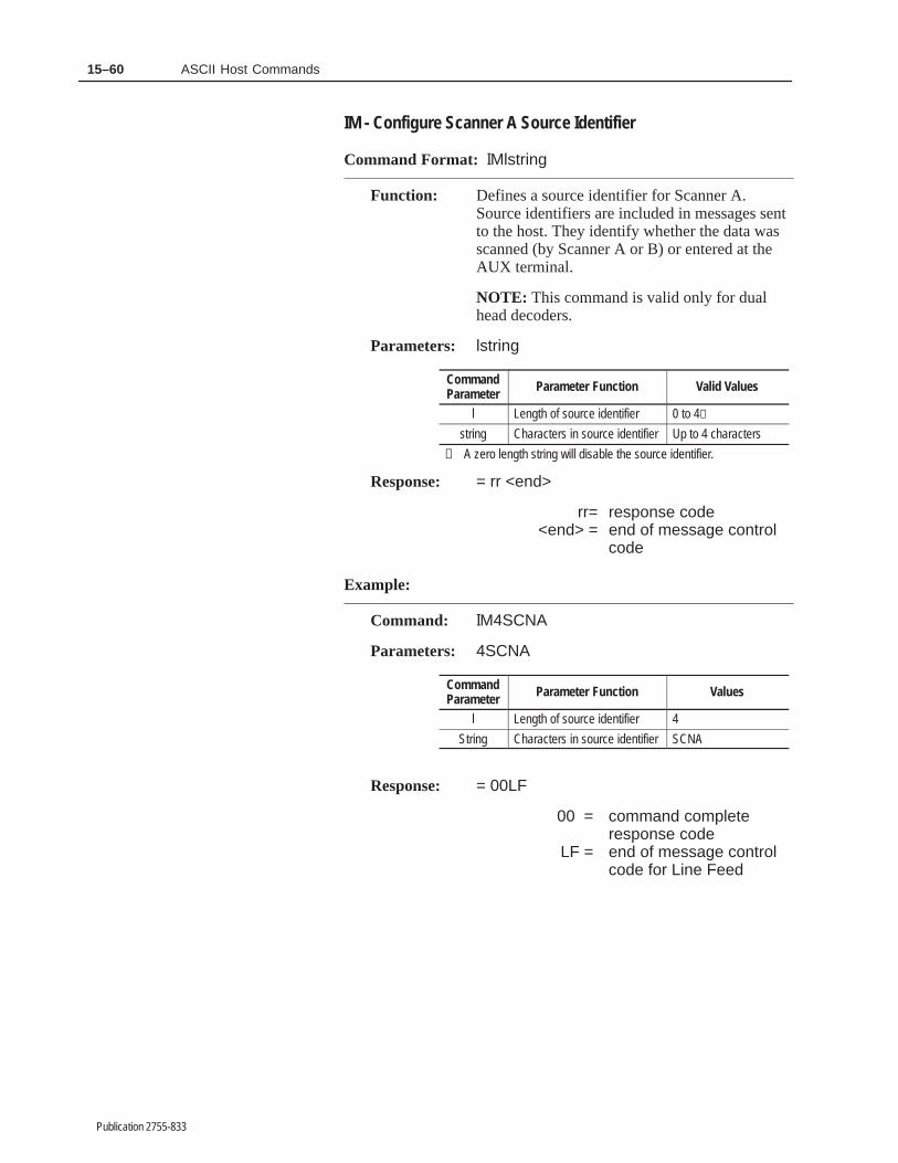
15–60 ASCII Host Commands
Publication 2755-833
IM - Configure Scanner A Source Identifier
Command Format: IMlstring
Function: Defines a source identifier for Scanner A.Source identifiers are included in messages sentto the host. They identify whether the data wasscanned (by Scanner A or B) or entered at theAUX terminal.
NOTE: This command is valid only for dualhead decoders.
Parameters: lstring
CommandParameter Parameter Function Valid Values
l Length of source identifier 0 to 4①
string Characters in source identifier Up to 4 characters
① A zero length string will disable the source identifier.
Response: = rr <end>
rr= response code <end> = end of message control
code
Example:
Command: IM4SCNA
Parameters: 4SCNA
CommandParameter Parameter Function Values
l Length of source identifier 4
String Characters in source identifier SCNA
Response: = 00LF
00 = command completeresponse code
LF = end of message controlcode for Line Feed

15–61ASCII Host Commands
Publication 2755-833
IB - Configure Scanner B Source Identifier
Command Format: IBlstring
Function: Defines a source identifier for Scanner B.Source identifiers are included in messages sentto the host. They identify whether the data wasscanned (by Scanner A or B) or entered at theAUX terminal.
NOTE: This command is valid only for dualhead decoders.
Parameters: lstring
CommandParameter Parameter Function Valid Values
l Length of source identifier 0 to 4①
String Characters in source identifier Up to 4 characters
① A zero length string will disable the source identifier.
Response: = rr <end>
rr = response code <end> = end of message control code
Example:
Command: IB4SCNB
Parameters: 4SCNB
CommandParameter Parameter Function Values
l Length of source identifier 4
String Characters in source identifier SCNB
Response: = 00LF
00 = command completeresponse code
LF= end of message control codefor Line Feed

15–62 ASCII Host Commands
Publication 2755-833
HM - Configure Header Message
Command Format: HMIIstring
Function: Defines a header message for bar code data.
Parameters: llstring
CommandParameter Parameter Function Valid Values
ll Length of header message 00 to 32①
String Header message characters Up to 32 characters
① A zero length string will disable the header message.
Response: = rr <end>
rr = response code<end> = end of message control code
Example:
Command: HM03A-B
Parameters: 03A-B
CommandParameter Parameter Function Values
ll Length of header message 03
String Header message characters A-B
Response: = 00LF
00 = command completeresponse code
LF = end of message control codefor Line Feed

15–63ASCII Host Commands
Publication 2755-833
NM - Configure Default No-Read String
Command Format: NMIIstring
Function: Defines a no-read message for bar codes thatcould not be scanned or decoded. No-readmessages are optionally included in messagessent to the host.
Parameters: llstring
CommandParameter Parameter Function Valid Values
ll Length of no-read message 00 to 32①
String No-read message characters Up to 32 characters
① A zero length string disables a no read string.. A nonzero length stringenables the no read string
Response: = rr <end>
rr = response code <end> = end of message control code
Example:
Command: NM07NO-READ
Parameters: 07NO-READ
CommandParameter Parameter Function Values
ll Length of no-read message 07
String No-read message characters NO-READ
Response: = 00CR
00 = command completeresponse code
CR = end of message control codefor Carriage Return

15–64 ASCII Host Commands
Publication 2755-833
AX - Configure AUX Terminal Data Entry Operations
Command Format: AXabceeefgg
Function: Configures AUX terminal data entry parameters.These parameters take effect when the AUX portis set to manual data entry mode (as described inChapter 13).
Parameters: abceeefgg
CommandParameter Parameter Function Valid Values
a Enable keyboard entry?0= No1= Yes2= No-Read
b Confirm entry? 0= No1= Yes
c Format AUX Keyboard Data? 0= Unformatted1= Host Format
eee Rubout character forkeyboard data entry?
ASCII Decimal Value000 to 255255 = None
f Echo keyboard data? 0= No1= Yes
gg Size of the display. 10 through 80
Response: = rr <end>
rr= response code<end>= end of message control code

15–65ASCII Host Commands
Publication 2755-833
AX - Configure AUX Terminal Data Entry Operations (continued)
Example:
Command: AX111008180
Parameters: 111008180
CommandParameter Parameter Function Values
a Enable keyboard entry? 1= Yes
b Confirm entry? 1= Yes
c Format Aux TerminalKeyboard Data?
1= Host Format
eee Rubout character forkeyboard data entry
ASCII Decimal Value008 = backspace
f Echo keyboard data? 1= Yes
gg Size of the display. 80
Response: = 00CR
0= response codeCR= end of message control code

15–66 ASCII Host Commands
Publication 2755-833
TM - Display Text Message at AUX Terminal and LCD
Command Format: TMfllstring
Function: Sends a message to the AUX port terminal(and/or LCD Display) and optionally enables thekeyboard for one message. If a text message isnot defined, the Default Prompt Message is sent.
Parameters: fllstring
CommandParameters Parameter Function Valid Values
f Enable keyboard entry for onemessage.
1= Yes0= No
ll Length of text message. 00 through 80
String Text message characters. Up to 80 characters
Response: = rr <end>
rr= response code (see Table17.D)
<end>= end of message control code
Note: If the previous message has not displayed,the response returns a code of 02 to indicate thecommand failed because the display buffer wasnot available.
If the AUX port is set to configuration mode,(CONFIG jumper is open), the response returnsa code of 01. The message will display on theLCD Display but not the AUX terminal.

15–67ASCII Host Commands
Publication 2755-833
TM - Display Text Message at AUX Terminal and LCD (continued)
Example:
Command: TM111MESSAGETEXT
Parameters: 111MESSAGETEXT
CommandParameters Parameter Function Values
f Enable keyboard entry for onemessage.
1= Yes
ll Length of text message. 11
String Text message characters. MESSAGETEXT
Response: =00CR
00 = command completeresponse code
CR= end of message control codefor Carriage Return

15–68 ASCII Host Commands
Publication 2755-833
PM - Default Prompt Message for AUX Terminal
Command Format: PMllstring
Function: Defines the default prompt message for theAUX port terminal.
Parameters: llstring
CommandParameters Parameter Function Valid Values
ll Length of the AUX terminalprompt message
00 through 20
String AUX terminal promptmessage string.
Up to 20 characters
Response: = rr <end>
rr = response code<end>= end of message control code
Example:
Command: PM11ENTER DATA:
Parameters: 11ENTER DATA:
CommandParameters Parameter Function Values
ll Length of the AUX terminalprompt message
11
String AUX terminal promptmessage string.
ENTER DATA:
Response: =00CR
00 = command completeresponse code
CR = end of message control codefor Carriage Return

15–69ASCII Host Commands
Publication 2755-833
PI - Read Decoder Performance Indicators
Command Format: PI
Function: Reads the decoder performance indicators forScanners A and B.
Parameters: None
ResponseParameters Parameter Function Valid Values
aaa Scanner A PerformanceIndicator
3 digit value000 through 100, 999①
bbb Scanner B PerformanceIndicator
3 digit value000 through 100,999①②
① 999 indicates the decoder is not decoding because of a buffer overflowcondition.
② Applicable only with dual head scanner.
Response: aaa<end> = rr <end> for single head scanners,oraaabbb<end> = rr <end> for dual headscanners.
<end>= end of message code rr= response code
<end>= end of message codeExample:
Command: PI
Response: 000099LF = 00LF
ResponseParameters Parameter Function Values
aaa Scanner A PerformanceIndicator
000
bbb Scanner B PerformanceIndicator
099
LF= end of message control code00= command complete
response code LF= end of message control code

15–70 ASCII Host Commands
Publication 2755-833
PR - Read Package Counter
Command Format: PR
Function: Returns the count maintained by the packagecounter.
Parameters: None
Response: pppppp<end>= rr <end>
pppppp= package count, up to999999
<end>= end of message control coderr = response code
<end>= end of message control codeExample:
Command: PR
Response: 000075LF = 00LF
000075= number of packages read bydecoder
LF= end of message code forLine Feed
00= command completeresponse code
L= end of message code forLine Feed

15–71ASCII Host Commands
Publication 2755-833
NR - Read Symbols Not Read Counter
Command Format: NR
Function: Returns the count in the no-read counter.
Parameters: None
Response: pppppp<end>= rr <end>
pppppp = no-read count, up to 999999 <end> = end of message control code
rr= response code <end>= end of message control code
Example:
Command: NR
Response: 000016CR = 00CR
000016= no-read count of 16CR= end of message control code
for Carriage Return 00 = command complete
response code CR= end of message control code
Carriage Return

15–72 ASCII Host Commands
Publication 2755-833
MC - Read Output Counter
Command Format: MCn
Function: Reads the selected output counter.
Parameters: n = counter 1 through 8
Response: mmmmmm<end>=rr<end>
mmmmmm= output counter count.Maximum value of 999999
<end>= end of message code rr= response code
<end>= end of message codeExample:
Command: MC3
Parameters: 3 = read output counter #3.
Response: 000121LF = 00LF
000121= Counter activated 121 timessince last restart or reset
LF= end of message code forLine Feed
00= command completeresponse code
LF= end of message code forLine Feed

15–73ASCII Host Commands
Publication 2755-833
PC - Clear Package Counter
Command Format: PC
Function: Clears the package counter to 0.
Parameters: None
Response: = rr <end>
rr= response code <end>= end of message control code
Example:
Command: PC
Response: = 00 <CR>
00= command completeresponse code
CR= end of message control code
NC - Clear Symbols Not Read Counter
Command Format: NC
Function: Clears the no-read counter to 0.
Parameters: None
Response: = rr <end>
rr= response code<end>= end of message control code
Example:
Command: NC
Response: = 00CR
0= command completeresponse code
CR= end of message control codefor Carriage Return

15–74 ASCII Host Commands
Publication 2755-833
RN - Save Configuration to Storage Memory and Restart
Command Format: RN
Function: Saves current configuration in to storagememory and restarts the decoder. Operation thenresumes using the new configuration parameters.
Parameters: None
Response: = 97 <end>
97= Indicates the command wasreceived and the decoder isresetting. The reset takesapproximately 5 seconds.
<end>= end of message code
SA - Save Configuration to Storage Memory (No Restart)
Command Format: SA
Function: Saves current configuration to storage memory.
Parameters: None
Response: = 00 <end>
00 = Indicates the command wasreceived
<end>= end of message code
Important: Host communication parameterchanges do not take effect until the decoder isrestarted.

15–75ASCII Host Commands
Publication 2755-833
DD - Set Configuration to Default Values
Command Format: DD
Function: Sets configuration in operating memory to thedefault values.
Important: Host port communicationparameters and the contents of storage memoryare not changed with the DD command.
Parameters: None
Response: = rr<end>
rr = response code<end>= end of message control code
Example: DD
Command: DD
Response: = 00CRLF
00 = command completeresponse code
CRLF = end of message control codefor Carriage Return andLine Feed.
RD - Set Configuration to Factory Defaults and Restart
Command Format: RD
Function: Resets decoder to factory defaults, saves theconfiguration in storage memory, and thenrestarts the decoder. Operation then resumesusing the new configuration parameters. Refer toAppendix B for factory default settings.
Important: Host port communicationparameters are not changed to default valueswith this command.
Parameters: None
Response: = 98 <end>
98 = Indicates the command wasreceived and the decoder isresetting. The reset takesapproximately 5 seconds.
<end>= end of message control code

15–76 ASCII Host Commands
Publication 2755-833
RE - Reset Decoder
Command Format: RE
Function: Resets decoder. Recalls the configuration fromstorage memory and restarts the decoder.
Parameters: None
Response: = 97 <end>
97 = Indicates the command wasreceived and the decoder isresetting. The reset takesapproximately 5 seconds.
<end>= end of message code
ID - Version of Software
Command Format: ID
Function: Read the version of decoder software presentlyrunning.
Parameters: None
Response: aa.aa <end>=00<end>
aa.aa = Software revision number00 = Complete and successful
response code<end>= end of message control code

15–77ASCII Host Commands
Publication 2755-833
DM – Configure Bar Code Data Mask
Command Format: DM
Function: Obsolete command. Formerly used to define adata mask to return and/or suppress selectedcharacters in each field sent to the host. HostMessage Replacement Rules replace thisfunction.
Response: =50 rr <end>
50= Unknown Commandresponse code
<end>= end of message control code
PD - Configure Pad Data Character
Command Format: PD
Function: Obsolete command. Formerly used to definethepad character for the bar code data maskcommand (DM), which is not used in this series.
Response: =50 rr <end>
50= Unknown Commandresponse code
<end>= end of message control code
����� ��
Publication 2755-833
���� �� ������
This chapter defines PCCC (Programmable ControllerCommunications Commands) commands you can send from a hostto the decoder using the DH485 interface. These commands allowyou to use binary data exchange to configure the decoder, read datafrom the decoder, and obtain diagnostic information.
The PCCC host commands use the Allen-Bradley DH485 linkprotocol. To use these commands, the Host Protocol configurationparameter on the Host Communications configuration screen mustbe set to one of these options:
• DH485 PCCC-1 Protocol with Write Replies
• DH485 PCCC-2 Protocol without Write Replies
The decoder supports the following DH485 communicationaddresses:
DH485 LSAP Function
0 Diagnostic Commands (Perform Application Layer)
1 or 128 PCCC Commands (Perform Application Layer)
129 Perform Link Reset-immediate Block
The PCCC commands perform the same functions as theconfiguration screens and fall into three categories:
1. Unprotected Read Command The unprotected read command isused to read bar code data, configuration data, counter values,performance indicators and the last message sent to host.
2. Unprotected Write Command The unprotected write commandis used to modify (or write over) configuration data, clearcounters, flush data, set defaults, and perform other functions.
3. Diagnostic Command The diagnostic command is used to readlink layer diagnostic counters and statuses, reset diagnosticcounters, and perform a diagnostic loop.
Chapter Objectives
Protocol Options
PCCC Commands

16–2 PCCC Host Commands
Publication 2755-833
!ATTENTION: When controlling discrete outputslocally using AUX port configuration, suspend hostcommunications to prevent outputs fromunintentionally changing state.
Command Format
The general structure and definitions of all commands is shownbelow. The structure shows the high and low byte of each data word(word= 2 bytes). Data is always transmitted with the low byte of eachdata word first and then the high byte. In the command explanationsbelow, MSB stands for Most Significant Bit, and LSB stands forLeast Significant Bit.
5
0STS CMD
High Address FNC Code or Low Address
Transaction Number Sequence (TNS)
Data
122 or 124 bytes maximum
High Byte Low ByteMSB LSB
1
3 2
4
6.
.
.
126
7.
.
.
127
• CMD
Byte 0 specifies the command to perform.
Bits 0, 1, 2 and 3 of the CMD byte contain the command code.The options are:
– 0001(01H) = Unprotected Read Command– 1000 (08H) = Unprotected Write Command– 0110 (06H) = Diagnostic Command
Bit 6 is cleared (0) for the command and set (1) for the reply.
Bit 4, 5, and 7 are always zero.
To send an unprotected write command, CMD byte 0 would looklike this:
LSB
0 0 0 0 1 0 0 0
7 6 5 4 3 2 1 0
1000 = Unprotected Write (08H)
Bit 6 cleared(0) for com-mand
Always 0
MSB

16–3PCCC Host Commands
Publication 2755-833
• STS
Byte 1 specifies the command status which is always 0.
• TNS
Bytes 2 and 3 contain a unique transaction number sequence that links each command to a reply. The TNS is user defined.
• FNC Code
When the CMD byte = 06H (diagnostic command), byte 4specifies a diagnostic function. For example, FNC = 01 meansread diagnostic counters.
• Low Address
When the CMD byte = 01H (unprotected read command) or 08H(unprotected write command) byte 4 contains the low byte of atwo byte address.
The low address (byte 4) and high address (byte 5) map to aspecific area in decoder memory for a read or write operation.
• High Address
When the CMD byte = 01H (unprotected read command) or 08H(unprotected write command) byte 5 contains the high byte of atwo byte address.
The low address (byte 4) and high address (byte 5) map to aspecific area in decoder memory for a read or write operation.
• Data
The data area is command dependent. The starting byte for thedata area is also command dependent.
Command Reply Format
The general format and definition of a command reply is:
0STS CMD Reply
TNS
Data 124 bytes maximum
High Byte Low ByteMSB LSB
1
3 2
4.
.
.
126
5.
.
.
127
Optional
• CMD Reply
Byte 0 contains the response to a command. Bit 6 is set for thereply and responses are:

16–4 PCCC Host Commands
Publication 2755-833
– 41H – Response to an unprotected read (01H) command– 46H – Response to a diagnostic link (06H) command– 48H – Response to an unprotected write (08H) command
If the CMD byte sent in any of the commands is invalid, the STSbyte will contain 10H.
• STS
Byte 1 contains the status of a processed command. The tablebelow lists the STS codes for all commands.
Status Response Codes
Hex Value Meaning
00H Command successful (no errors).
01H Command complete and successful.➀
02H Display buffer is full. ➀
10H Valid command but invalid format or address.
20H Invalid or unsupported command.
30H Hardware fault (reserved and unused).
40H Command successful but no data available(read command only)
80H Command successful but data truncated.(read command only)
➀ Applies only to CMD Address 900H or 901H. See page 16–12
• TNS
Bytes 2 and 3 contain the same transaction number sequence asthe command. The TNS value links the reply to the command.
• Data
The data area contains data requested by a read command. Thewrite commands do not return data.
The unprotected read command (01H) performs these decoderfunctions:
• Reads current bar code data
• Reads decoder configuration data
• Reads decoder performance indicator, counters, and diagnostics
• Reads last message to host
Each command returns data to the host that is read from a specificaddress of the decoder’s memory. The following sections define eachread command.
Appendix A contains a summary of the memory addresses for alldecoder functions or commands.
Unprotected ReadCommand

16–5PCCC Host Commands
Publication 2755-833
Read Current Bar Code Data
Bar code data is stored as a packet in the host buffer of the decoder ataddress 100H to 3BFH. Each packet contains data from one readoperation. The maximum number of bytes in one packet is 704 bytes.
To read the current bar code data, send this command structure:
0
2
4
6
5
1
3
7
STS= 00
Host Buffer Address= 100H
TNS
High Byte Low ByteMSB LSB
CMD= 01H
Size = n
Read Current Bar Code Data Command
00H
Each command can return up to 124 (7C Hex) bytes of data, which isdetermined by the size byte (byte 6). The amount of data in the hostbuffer is variable.
The size of the reply varies depending on how much data is in thehost buffer and the number of bytes specified in the size byte.
If the host buffer is empty, the reply is returned without data and astatus of 40H (no data in host buffer).
0STS= 40H
TNS
High Byte Low ByteMSB LSB
1
3 2
CMD Reply = 41H
Reply - No Data in Host Buffer
If the host buffer contains data ≤ the number of bytes specified inthe size byte, the reply returns all data and a status of 00H (noerrors).
0
5
STS= 00H
TNS
High Byte Low ByteMSB LSB
1
3 2
4
Reply - All Data Returned in Host Buffer
Data
CMD Reply = 41H
If the host buffer contains more data than the number of bytesspecified in the size byte, the reply is returned with truncated dataand a status of 80H (data truncated).
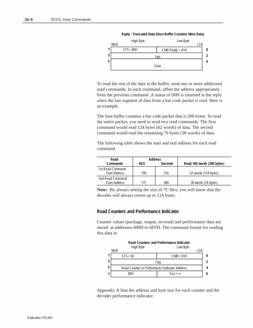
16–6 PCCC Host Commands
Publication 2755-833
0
5
STS= 80H
TNS
High Byte Low ByteMSB LSB
1
3 2
4
Reply - Truncated Data (Host Buffer Contains More Data)
Data
CMD Reply = 41H
To read the rest of the data in the buffer, send one or more additionalread commands. In each command, offset the address appropriatelyfrom the previous command. A status of 00H is returned in the replywhen the last segment of data from a bar code packet is read. Here isan example.
The host buffer contains a bar code packet that is 200 bytes. To readthe entire packet, you need to send two read commands. The firstcommand would read 124 bytes (62 words) of data. The secondcommand would read the remaining 76 bytes (38 words) of data.
The following table shows the start and end address for each readcommand.
Read Commands
Address HEX Decimal Read 100 words (200 bytes)
1st Read CommandStart Address 100 256 62 words (124 bytes)
2nd Read CommandStart Address 17C 380 38 words (76 bytes)
Note: By always setting the size of 7C Hex, you will know that thedecoder will always return up to 124 bytes.
Read Counters and Performance Indicator
Counter values (package, output, no-read) and performance data arestored at addresses 600H to 6FFH. The command format for readingthis data is:
0
2
4
6
5
1
3
7
STS= 00
Read Counter or Performance Indicator Address TNS
High Byte Low ByteMSB LSB
CMD= 01H
Size = n
Read Counters and Performance Indicator
00H
Appendix A lists the address and byte size for each counter and thedecoder performance indicator.
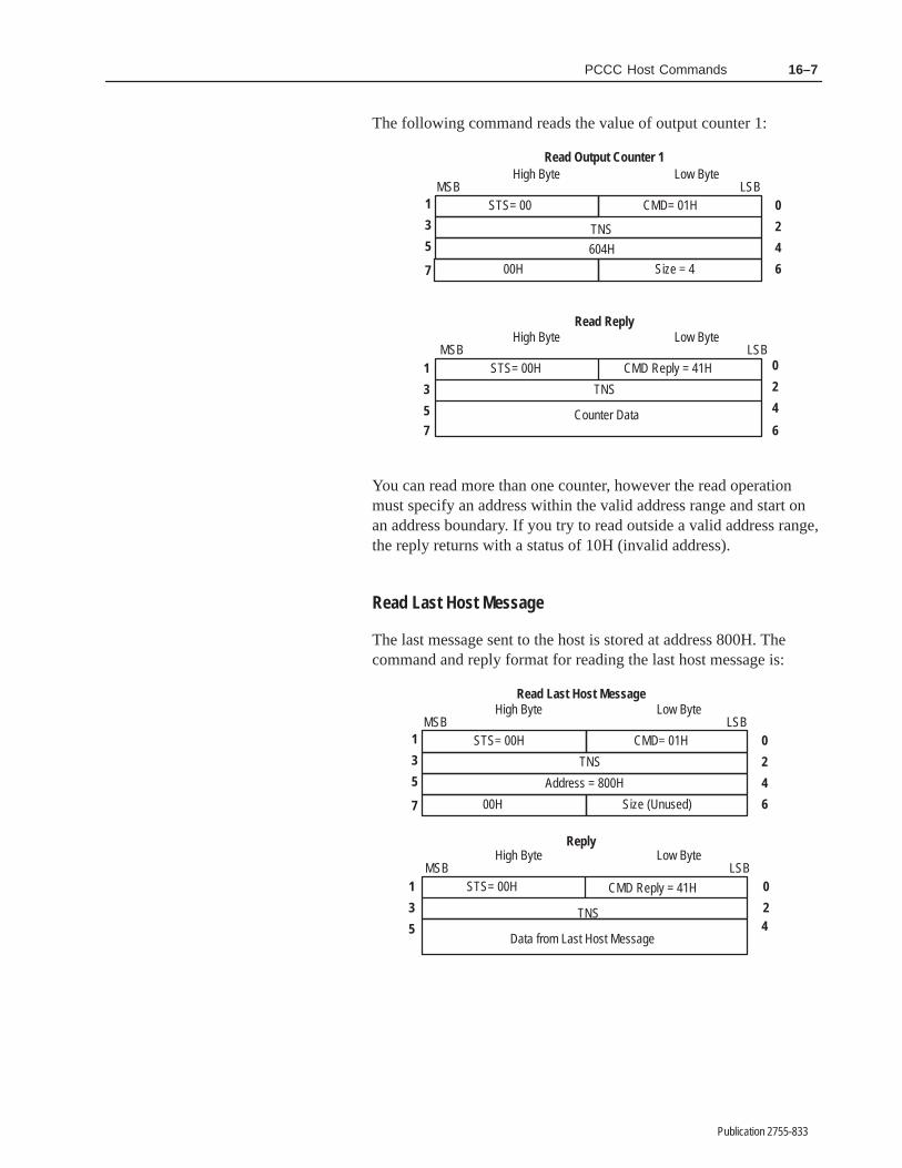
16–7PCCC Host Commands
Publication 2755-833
The following command reads the value of output counter 1:
7
5
1
3 2
4
6
0
0
2
45
1
3
STS= 00
TNS
High Byte Low ByteLSB
Size = 4
Read Output Counter 1
00H
STS= 00H
TNS
High Byte Low ByteMSB LSB
Read Reply
Counter Data
604H
7 6
CMD Reply = 41H
CMD= 01HMSB
You can read more than one counter, however the read operationmust specify an address within the valid address range and start onan address boundary. If you try to read outside a valid address range,the reply returns with a status of 10H (invalid address).
Read Last Host Message
The last message sent to the host is stored at address 800H. Thecommand and reply format for reading the last host message is:
0
2
4
6
5
1
3
0
24
5
1
3
7
STS= 00H
Address = 800H
TNS
High Byte Low ByteMSB LSB
CMD= 01H
Size (Unused)
Read Last Host Message
00H
STS= 00H
TNS
High Byte Low ByteMSB LSB
Reply
Data from Last Host Message
CMD Reply = 41H

16–8 PCCC Host Commands
Publication 2755-833
Read Decoder Configuration Data
Appendix A lists the address location for each configurationparameter along with the byte size of the data and the default value.To read or examine one or more parameters, send the read commandwith the appropriate starting address and byte size referenced inAppendix A.
5
1
3
7
0
2
4
6
STS= 00H
Configuration Data Address (300H to 5FFH) TNS
High Byte Low ByteMSB LSB
CMD= 01H
Size = n
Read Configuration Data
00H
The reply returns the configuration data at the specified address.
0
5
STS= 00H
TNS
High Byte Low ByteMSB LSB
1
3 2
4
Reply to Read Configuration Data
Configuration Data
CMD Reply = 41H
You can read more than one parameter, however the read operationmust specify an address within the valid address range and start on aparameter boundary. If you try to read outside a valid address range,the reply returns with a status of 10H (invalid address).
The unprotected write command (08H) performs these decoderfunctions:
• Modifies (or writes over) decoder configuration data
• Executes a decoder function
• Sends a repeat read command
• Sends a message to the AUX port terminal and LCD Display
• Holds a discrete output on or off
Each command modifies (or overwrites) data at a specific address indecoder memory or executes a specific decoder function. Thefollowing sections define each of the write commands.
Important: If the configuration date is a text string, you must sendthe length of the string as the first byte of the string.
Unprotected WriteCommand
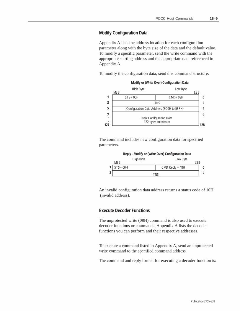
16–9PCCC Host Commands
Publication 2755-833
Modify Configuration Data
Appendix A lists the address location for each configurationparameter along with the byte size of the data and the default value.To modify a specific parameter, send the write command with theappropriate starting address and the appropriate data referenced inAppendix A.
To modify the configuration data, send this command structure:
5
1
3
7
127
.
.
. 128
0
2
4
6
STS= 00H
Configuration Data Address (3C0H to 5FFH)
TNS
High Byte Low ByteMSB LSB
CMD= 08H
Modify or (Write Over) Configuration Data
New Configuration Data122 bytes maximum
.
.
.
The command includes new configuration data for specifiedparameters.
0STS= 00H
TNS
High Byte Low ByteMSB LSB
1
3 2
Reply - Modify or (Write Over) Configuration Data
CMD Reply = 48H
An invalid configuration data address returns a status code of 10H (invalid address).
Execute Decoder Functions
The unprotected write (08H) command is also used to executedecoder functions or commands. Appendix A lists the decoderfunctions you can perform and their respective addresses.
To execute a command listed in Appendix A, send an unprotectedwrite command to the specified command address.
The command and reply format for executing a decoder function is:

16–10 PCCC Host Commands
Publication 2755-833
1
3
0
2STS= 00H
TNS
High Byte Low ByteMSB LSB
Reply
CMD Reply = 48H
5
1
3 2
4
0STS= 00H
Command Address = 600H through 639H,640H, 641H
TNS
High Byte Low ByteLSB
CMD= 08H
Execute Decoder Function
MSB
If you send a command with an invalid address, the reply returns astatus code of 10H (invalid address).
To set the current configuration to the factory defaults, send thiscommand:
2
4
0
5
1
3
STS= 00H
Command Address = 633H TNS
High Byte Low ByteMSB LSB
CMD= 08H
Set Decoder Configuration to Defaults
To save the current configuration and restart the decoder, send thiscommand:
5
1
3 2
4
0STS= 00H
Command Address = 632H
TNS
High Byte Low ByteMSB LSB
CMD= 08H
Save Configuration and Restart Decoder
To clear output counter 4 to all zeros, send this command:
5
1
3 2
4
0STS= 00H
Command Address = 610H
TNS
High Byte Low ByteMSB LSB
CMD= 08H
Clear Output Counter 4

16–11PCCC Host Commands
Publication 2755-833
Send Repeat Read Command
The Repeat Read command tells the decoder to wait for bar codedata. When data is available, the decoder sends it to a specificaddress in host memory using the unprotected write (08H) command.The host does not have to request data at each poll when a 2760-RBis used (RB polls automatically). The decoder automatically sendsbar code data as it is decoded.
The command structure for sending a repeat read command is:
5
1
3
9
7
0
2
4
8
6
STS= 00
Command Address= 640H
TNS
High Byte Low ByteMSB LSB
CMD= 08H
Size = n
Repeat Read Command
Repeat Count= n
Starting Target Host Address
• Command Address
Bytes 4 and 5 contain address 640H. This address tells thedecoder to perform a repeat read command.
• Target Host Address
Specifies the host address to which the decoder will send the readreply data.
• Size
Byte 8 specifies the maximum number of bytes sent to the host ineach read reply. The maximum size is 122 bytes.
• Repeat Count
Byte 9 specifies the maximum number of bar code packets thatcan be sent to the host. A value of 0 means the decoder can sendpackets until terminated by a “Cancel Repeat Read” command..
After the host sends the repeat read command, the decoder generatesan unprotected write command to send the bar code data to the host.
The decoder continues to send data to the host until the repeat countis reached or until a Cancel Repeat command is sent to the decoder.
The amount of data returned in the read reply is determined by thesize parameter and the amount of data in the host buffer.
If the repeat count is non zero, the repeat count automaticallydecrements by one and the repeat read command continuesprocessing. When the repeat count decrements to zero, the repeatread command terminates.
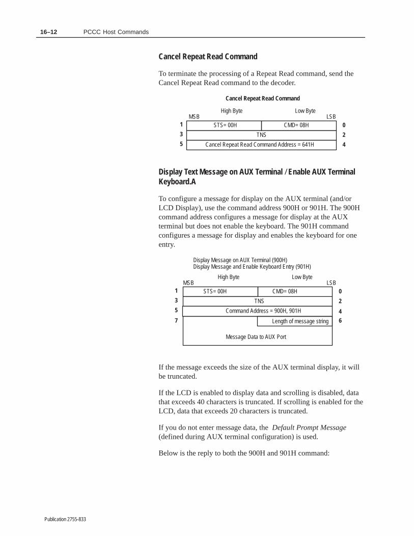
16–12 PCCC Host Commands
Publication 2755-833
Cancel Repeat Read Command
To terminate the processing of a Repeat Read command, send theCancel Repeat Read command to the decoder.
5
1
3 2
4
0STS= 00H
Cancel Repeat Read Command Address = 641H
TNS
High Byte Low ByteMSB LSB
CMD= 08H
Cancel Repeat Read Command
Display Text Message on AUX Terminal / Enable AUX TerminalKeyboard.A
To configure a message for display on the AUX terminal (and/orLCD Display), use the command address 900H or 901H. The 900Hcommand address configures a message for display at the AUXterminal but does not enable the keyboard. The 901H commandconfigures a message for display and enables the keyboard for oneentry.
0
5
STS= 00H
TNS
High Byte Low ByteMSB LSB
1
3 2
6
CMD= 08H
Display Message on AUX Terminal (900H)Display Message and Enable Keyboard Entry (901H)
Message Data to AUX Port
Command Address = 900H, 901H 4
7 Length of message string
If the message exceeds the size of the AUX terminal display, it willbe truncated.
If the LCD is enabled to display data and scrolling is disabled, datathat exceeds 40 characters is truncated. If scrolling is enabled for theLCD, data that exceeds 20 characters is truncated.
If you do not enter message data, the Default Prompt Message(defined during AUX terminal configuration) is used.
Below is the reply to both the 900H and 901H command:

16–13PCCC Host Commands
Publication 2755-833
0STS= 00H
High Byte Low ByteMSB LSB
1
3 2
Command Replies
CMD Reply = 48H
TNS
If the AUX port is not set to manual data entry mode (CONFIGjumper is open), the LCD will display the message but not the AUXterminal. The command returns a status of 01H.
If the decoder has not processed the previous text message, thecommand returns a status of 02H indicating the command failedbecause the display buffer was not available.
Hold Discrete Output Open or Closed
Allows the host to control the discrete outputs (regardless of their”normal” state) for a set duration. When the specified durationexpires, the output reverts to its previous state.
If a normally open (or closed) output is held open (or closed), thestate of the output will not change due to other conditions.
0
5
STS= 00H
TNS
High Byte Low ByteLSB
1
3 2
6
CMD= 08H
Holds Discrete Output Open or Closed
Command Address = (see Appendix A) 4
7 Pulse Duration (in milliseconds)
MSB
0STS= 00H
TNS
High Byte Low ByteMSB LSB
2
Command Reply
1
3
CMD Reply = 48H
Appendix A lists the command addresses for holding a discreteoutput (1-8) open or closed. Valid duration values (in milliseconds)are 0010 through 9999. Note that the duration must be expressed inhex format (0A through 270F hexadecimal).

16–14 PCCC Host Commands
Publication 2755-833
0
5
00H
TNS
High Byte Low ByteLSB
1
3 2
6
08H
Example (holds output closed for 10 milliseconds)
4
7
MSB
06H 60H
00H 0AH
Important: A duration of 0000 holds the specified output in theprogrammed state until it is changed with another host command orvia the AUX terminal configuration screens. The condition field onthe AUX terminal will display Open or Closed.
The diagnostic commands (06H) allow you to obtain diagnostic dataon an DH485 communications link. The decoder supports thesediagnostic commands:
• Diagnostic Loop (CMD= 06H, FNC= 00H)
• Read Diagnostic Counters (CMD= 06H, FNC= 01H)
• Read Diagnostic Status (CMD= 06H, FNC= 03H)
• Reset Diagnostic Counters (CMD= 06H, FNC= 07H)
The command code for all diagnostic functions is 06H. A functioncode (FNC) identifies each command and specifies which commandto perform.
Diagnostic Loop
The Diagnostic Loop Command (CMD= 08H, FNC= 00H) echoesdata back to the host. The reply returns the same data sent in theDiagnostic Loop Data area of the command. The data area cancontain up to 122 bytes.
Diagnostic LinkCommands

16–15PCCC Host Commands
Publication 2755-833
0
5
STS= 00H
High Byte Low ByteMSB LSB
1
3 2
4
CMD= 06H
Diagnostic Loop Command
0STS= 00H
High Byte Low ByteMSB LSB
2
4
Diagnostic Loop Reply
5
1
3
FNC=00H
CMD Reply = 46H
TNS
Diagnostic Loop Data122 bytes maximum
TNS
Diagnostic Loop Data(same data as in command)
Read Diagnostic Counters
The Read Diagnostic Counters command (CMD= 06H, FNC= 01H)returns diagnostic counter values. The command structure looks likethis:
0STS= 00H
High Byte Low ByteMSB LSB
1
3 2
4
CMD= 06H
Read Diagnostic Counters Command
0STS= 00H
High Byte Low ByteMSB LSB
2
8
Read Diagnostic Counters Reply
5
1
3
FNC=01H
4
7 6
9 Msg ACK-Timeout/RetriesMsg Retry Failures
Msg Replies: NAK-NoMemoryMsg Recvd: NAK-NoMemory
Msg Replies: NAK-SolicitMsg Replies: NAK-TooBig
11
15
10
14
The reply returns values for ten diagnostic counters. The reply format looks like this:
Bad Messages ReceivedMsg Replies: NAK-NoService13 12
CMD Reply = 46H
TNS
TNS
Total Message Packets Received (2 bytes)
Total Message Packets Transmitted (2 bytes)

16–16 PCCC Host Commands
Publication 2755-833
Each diagnostic counter increments when the event occurs. TheReset Diagnostic Counters command resets all counter values to zero(0).
Reset Diagnostic Counters
The Reset Diagnostic Counters (CMD= 06H, FNC= 07) sets alldiagnostic counter values to zero (0). The command and replyformats look like this:
0STS= 00H
High Byte Low ByteMSB LSB
1
3 2
4
CMD= 06H
Reset Diagnostic Counters Command
0STS= 00H
High Byte Low ByteMSB LSB
2
Reset Diagnostic Counters Reply
1
3
FNC=07H
CMD Reply = 46H
TNS
TNS
Read Diagnostic Status
The Read Diagnostic Status command (CMD= 06H, FNC= 03H)returns seven diagnostic parameters in the reply:
Diagnostic Return Parameters
Parameter Value Bytes Size
Mode/Status 00 1 byte
Extended Type EEH 1 byte
Interface Type 22H 1 byte
Processor Type 21H 1 byte
Series/Revision 22H (Series B, Revision C) 1 byte
Bulletin Number/Product Name ASCII characters 11 bytes
Product Information unused 8 bytes
The command and reply format for the Read Diagnostic StatusCommand is:

16–17PCCC Host Commands
Publication 2755-833
1
3
0
2
4
STS= 00H
TNS
High Byte Low ByteMSB LSB
CMD= 06H
Read Diagnostic Status Command
0STS= 00H
High Byte Low ByteMSB LSB
2
Read Diagnostic Status Reply
1
3
FNC=03H
4EE 00621 228
”2” 2210
”5” ”7”12
”–” ”5”14
”D” (or “S”) ”D”
” ” ”1”
” ” ” ”
00 00
00 00
00 00
00 00
5
79
11
13
15
17
19
21
23
25
27
16
18
20
22
24
26
CMD Reply = 46H
TNS
The Series/Revision byte indicates the product series and revisionlevels. The three most significant bits indicate the series and theother five bits indicate the revision. For example, a value of 0 = A,1 = B, 2 = C.
Series A, Revision A returns as
Series B, Revision C returns as
000 00000
001 00010
A A
B C

����� ��
Publication 2755-833
��� �� � �� � �������������
This chapter provides troubleshooting information to assist withproblem detection and resolution. It also shows how to replace theI/O module protection fuses.
!ATTENTION: Always use caution when replacingfuses or installing accessories within the decoder.
The optional lithium backup battery (Catalog Number 1747–BA)will last up to five years. If installed, replace the battery five yearsfrom the date imprinted on the side of the battery cell. No otherbattery–related maintenance or service is required.
The battery clip is used only to hold the battery in position. It is notused to create an electrical circuit. Instead, the battery is equippedwith a female connector which attaches to the three–pronged maleconnector below it on the main circuit board.
To remove the battery, squeeze the narrow edges of the connector,and gently pull it away from the board. The connector is equippedwith a locking mechanism which releases when squeezed. Gentlyremove the battery from the mounting clip.
!ATTENTION: Be sure to follow all safetyprecautions regarding the handling and disposal oflithium batteries. Be sure to read and understand allmaterials accompanying the battery before attemptingto install it.
To install a new battery, insert the battery in the retaining clip on themain circuit board. Orientation of the battery in the clip makes nodifference, as the clip serves only to secure the battery in position.Place the female connector attached to the battery on thethree–pronged plug on the main circuit board. The plug will fit inonly one direction. If you feel resistance, reverse the plug and tryagain.
You will hear a click when the connector locking mechanismengages.
Chapter Objectives
Replacing the Battery
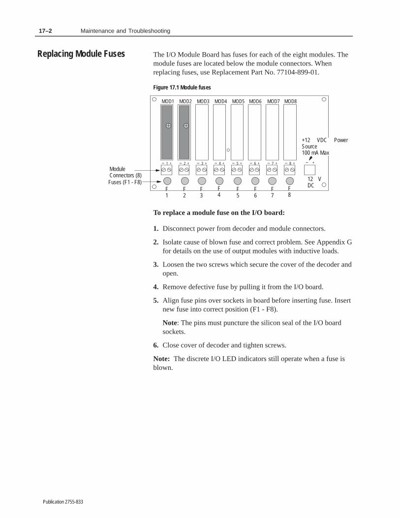
17–2 Maintenance and Troubleshooting
Publication 2755-833
The I/O Module Board has fuses for each of the eight modules. Themodule fuses are located below the module connectors. Whenreplacing fuses, use Replacement Part No. 77104-899-01.
Figure 17.1 Module fuses
Module Connectors (8)Fuses (F1 - F8)
MOD2 MOD3 MOD4 MOD6 MOD7 MOD8
– 1 +
MOD1
– +
12 VDC
– 2 + – 3 + – 4 +
MOD5
– 5 + – 6 + – 7 + – 8 +
F1
F2
F3
F4
F5
F6
F7
F8
+12 VDC PowerSource100 mA Max
To replace a module fuse on the I/O board:
1. Disconnect power from decoder and module connectors.
2. Isolate cause of blown fuse and correct problem. See Appendix Gfor details on the use of output modules with inductive loads.
3. Loosen the two screws which secure the cover of the decoder andopen.
4. Remove defective fuse by pulling it from the I/O board.
5. Align fuse pins over sockets in board before inserting fuse. Insertnew fuse into correct position (F1 - F8).
Note: The pins must puncture the silicon seal of the I/O boardsockets.
6. Close cover of decoder and tighten screws.
Note: The discrete I/O LED indicators still operate when a fuse isblown.
Replacing Module Fuses

17–3Maintenance and Troubleshooting
Publication 2755-833
This section lists problems that may occur with the decoder and/orconnected equipment. Each problem lists possible causes andsolutions.
Problem: Decoder ”Power On” indicator does not light.
Cause: Decoder power switch is in OFF position.
Solution: Turn decoder power switch to ON position.
Cause: No incoming power.
Solution: Verify power source.
Cause: Improper connection to power source.
Solution: Check connections.
Cause: Faulty decoder.
Solution: Return decoder to Allen-Bradley for repair.
Problem: Decoder ”Power On” indicator lights but ”CPUActive” indicator does not stay lit.
Cause: Internal decoder failure.
Solution: Return decoder to Allen-Bradley for repair.
Problem: Decoder ”Laser On” indicator lights but scanner”Laser On” indicator does not light.
Cause: Cable connections between decoder and scanner areloose or defective.
Solution: Check cable and connections.
Problem: Decoder ”Laser On” indicator does not light.
Cause: Wrong configuration.
Solution: Configure the Laser-On Mode parameter of thedecoder to ON.
Cause: Trigger not active. (Laser-on Mode parameter of decoderis set to Triggered).
Solution: Activate trigger and look at the Trigger Activeindicator on decoder. When the trigger is activated, the indicatorshould light.
Troubleshooting

17–4 Maintenance and Troubleshooting
Publication 2755-833
Problem: ”Laser On” indicators on both the decoder andscanner light but the scanner does not emit the laser light.
Cause: Mechanical shutter on scanner closed (2755-L4/L5scanners only).
Solution: Open shutter.
Cause: Scanner Laser On switch is in OFF position (2755-L7/L9scanners only).
Solution: Turn on switch.
Cause: Cable connections between decoder and scanner areloose or defective.
Solution: Check cable and connections.
Cause: Laser tube or diode burned out or defective.
Solution: Replace scanner.
Problem: Decoder ”Trigger Active” indicator will not light.
Cause: Wrong or improperly wired trigger source. (DecodeMode is set to Triggered).
Solution: Verify that an appropriate package detector is properlyconnected to the scanner. Most photoelectric package detectorshave a built-in LED. Verify operation of this package detect LED.Some photoelectric switches have sensitivity adjustments. Checkadjustment.
Cause: Cable connections between decoder and scanner areloose or defective.
Solution: Check cables and connections.
Problem: Decoder cannot read label.
Cause: Decoder not configured correctly.
Solution: Check decoder configuration to verify that parametersare set appropriately for your application.
Cause: Loose cables or connections.
Solution: Check cables and connections.
Problem: Decoder cannot read label.
Cause: Scanner is at incorrect angle or distance from the barcode.

17–5Maintenance and Troubleshooting
Publication 2755-833
Solution: Determine the optimum reading angle by using a staticbar code label position and checking the Decoder PerformanceIndicators with the Decode Mode set to Continuous. Fix thescanner at a position that produces a high decoder performancevalue. After properly positioning the scanner, return the decoderconfiguration to the correct triggered mode of operation.
Cause: Scanner lens is incorrect for the label size.
Solution: Select a scanner with a lens appropriate for the labelsize. Refer to scanner User Manual.
Cause: Label out of specification.
Solution: Use labels that are within industry standards.
Problem: Excessive ”No-Reads” during decoding.
Cause: Poor or marginal quality bar code labels.
Solution: Use labels that meet Automatic IdentificationManufacturer’s (AIM) specifications for the selected symbology.
Cause: Incorrect scanner selected for application.
Solution: Measure narrow bar width (or space, whichever isnarrowest) of bar code and note minimum and maximum readingdistance. Consult your scanner’s User Manual to verify that thesespecifications are within the proper guidelines for your scanner.
Cause: Scanner is at incorrect angle or distance from the barcode.
Solution: Determine the optimum reading angle by checking theDecoder Performance Indicators while the Decode Mode is set toContinuous and using a static bar code label position. Fix thescanner at a position that produces a high decoder performancevalue. After properly positioning the scanner, return the decoderconfiguration to the correct triggered mode of operation.
Cause: Package detect positioning.
Solution: Make sure the package detect signal is active beforethe bar code enters the laser beam. Check that package detect iscontinually blocked while in scanning area of laser. The ”TriggerActive” indicator should light when a bar code is scanned intriggered mode.
Cause: Scan speed not high enough or product line speed tohigh.

17–6 Maintenance and Troubleshooting
Publication 2755-833
Solution: Calculate ”scans per label” based on line speed and barcode orientation (picket fence or step ladder). Calculate at leastfive scans per label at full line speed. If calculation is less thanfive scans per label, select a higher speed scanner or reduceproduct line speed.
Problem: Output LED indicator does not operate.
Cause: Configuration parameters are not set correctly.
Solution: Review configuration parameters. The LED indicatorsare active for the duration set by the output duration parameter. Ifa duration is set to 0000, the LED will not change (although thecounters still increment). After making corrections, werecommend you, SAVE the changes and RESTART the decoder.
Cause: Outputs disabled.
Solution: Restart decoder.
Problem: Output LED indicator operates but output does not.
Cause: Improper connections.
Solution: Check connections to output modules. Verify thatpower is present. Check polarity of DC modules.
Cause: Output module fuse blown.
Solution: Determine reason for blown fuse, correct problem, andthen replace fuse.
Cause: Defective output module.
Solution: Replace defective module with new module.
Problem: Output module fuse 77104-899-01 blows.
Cause: Inductive device used with module has an inrush currentthat exceeds module specifications.
Solution: Replace the fuse and use a device rated within thespecification.
Problem: Output module (Catalog No. 2755-OB5S) blows.
Cause: Excessive back EMF of inductive load.
Solution: Install a rectifier diode in parallel with the module. SeeAppendix G.

17–7Maintenance and Troubleshooting
Publication 2755-833
Problem: Characters do not display or are difficult to read onthe LCD Display.
Cause: Inadequate contrast.
Solution: Improve readability of characters on LCD Display byadjusting LCD Display potentiometer on main logic board. SeeChapter 9 for details.
Problem: AUX Terminal is set to manual data entry mode, andterminal is displaying duplicate characters.
Cause: The terminal itself is set to echo data and the Echo toTerminal configuration parameter is also set to Yes.
Solution: Set the Echo to Terminal parameter to No.
Problem: AUX Terminal is set to manual data entry mode, andterminal is not displaying any characters.
Cause: Neither the terminal nor the decoder configuration is setto echo data.
Solution: Set the Echo to Terminal parameter to Yes.
Problem: No communication between decoder and AUXterminal.
Cause: Incorrect terminal selected from Select CRT Typescreen.
Solution: Select the correct terminal type. See Chapter 5.
Cause: Improperly connected cable.
Solution: Check connections. See Appendix D.
Cause: Improperly fabricated cable.
Solution: Verify connections. See Appendix D.
Cause: Incorrect terminal setup.
Solution: Verify that your terminal is set for 9600 baud, noparity, 1 stop bit. See Appendix D.
Problem: You cannot access the configuration screens on theAUX terminal.
Cause: The AUX port is set to manual data entry mode, notconfiguration mode.

17–8 Maintenance and Troubleshooting
Publication 2755-833
Solution: Place the AUX Terminal jumper on the logic board inthe CONFIG position and make sure the AUX port connectordoes not have a jumper between pins 15 and 16 (NEMA Type 1)or G and H (NEMA Type 4).
Problem: You are unable to perform manual data entryfunctions at the AUX terminal.
Cause: The AUX port is set to configuration mode, not manualdata entry mode.
Solution: Using one of the AUX Terminal Selectors, switch theAUX port to manual data entry mode. See Chapter 13.
Problem: No communication between decoder and host device.
Cause: Communication parameters (baud rate, parity, stop bits,host protocol) of decoder are not set correctly or the parameterswere not saved, and the decoder restarted.
Solution: Make appropriate changes to communicationparameters, SAVE the configuration, and RESTART the decoder.
Cause: Improperly connected cable.
Solution: Check connections.
Cause: Improperly fabricated cable.
Solution: Verify connections using Appendix E.
Cause: Flexible Interface Module (Catalog No. 2760-RB) is notconfigured properly.
Solution: Check module configuration.

����� ��
Publication 2755-833
������������
Electrical
Input Line Voltage 85 (Min) to 264 (Max) VAC100 to 240 VAC Nominal
Input Line Frequency 47 (Min) to 63 (Max) Hz; 50 to 60 HzNominalPower 80 VA Max (DD decoderss)
55 VA Max (DS decoders)
I/O Module Protection Fuse (Replacement Part No. 77104-899-01)
Output Module Voltage/CurrentCatalog No. 2755-0B5S 3-60 VDC, 0.5A MaxCatalog No. 2755-0A5S 12-140 VAC, 0.5A MaxCatalog No. 2755-0M5S 24-280 VAC, 0.5A Max
Input Module VoltageCatalog No. 2755-IB5S 3.3-32 VDCCatalog No. 2755-IA5S 90-140V RMS/DCCatalog No. 2755-IM5S 180-280V RMS/DC
MechanicalEnclosure
Catalog No. 2755-D_1_ NEMA Type 1Catalog No. 2755-D_4_ NEMA Type 4
LED IndicatorsPOWER ON GreenCPU ACTIVE GreenCOMMUNICATIONS YellowLASER ON A RedTRIGGER ACTIVE A YellowVALID READ A GreenLASER ON B RedTRIGGER ACTIVE B YellowVALID READ B GreenDISCRETE I/O 1 to 8 Red
Weight 10 lbs (4.5 kg) maximum, with all optionsinstalled
DimensionsInches 10.25 (H) x 12 (W) x 4.57 (D)Centimeters 26.0. (H) x 30.5 (W) x 11.6 (D)
EnvironmentAmbient Temperature
Operating 0 to 50° C (32 to 122° F)Storage -40 to 85° C (-40 to 185° F)
Relative Humidity 5 to 95%, noncondensing
Bar Code DecodersCatalog Numbers2755-DD1_ 2755-DD4_2755-DS1_ 2755-DS4_

18–2 Specifications
Publication 2755-833
Scanner PortsScanner Ports A and B
Connector (NEMA Type 1) 25-pin (female) subminiature DConnector (NEMA Type 4) 19-pin (male) circular Cannon KPT series
CommunicationsHOST Port
Electrical Standards RS232, RS422, RS485Protocols ASCII (RS232, RS422, DH485)
Allen-Bradley PCCC (RS485 only)Connector (NEMA Type 1) 25-pin (female) subminiature DConnector (NEMA Type 4) 19-pin (male) circular Cannon KPT series➀
Baud Rate 300, 1200, 2400, 4800, 9600, 19200, 38400Parity None, Odd, EvenData Bits 8 or 7Stop Bits 1 or 2Flow Control None, XON/XOFF, RTS/CTS
AUX PortElectrical Standard RS232Connector (NEMA Type 1) 25-pin (female) subminiature DConnector (NEMA Type 4) 19-pin (male) circular Cannon KPT series�➀Data Bits 8Stop Bit 1Baud Rate 9600Parity None
LCD Display (Optional)Number of lines 2Number of characters/line 20 characters/lineBacklighting Continuous LED backlighting
Decoded Symbologies Code 39 (Standard Character Set)Interleaved 2-of-5Code 128UPC-A with optional 2 or 5 digit supplementsUPC-E with optional 2 or 5 digit supplementsEAN-8 with optional 2 or 5 digit supplementsEAN-13 with opt. 2 or 5 digit supplementsCodabarPharma-Code
Certifications UL Listed
Listed to Canadian SafetyStandardsElectromagentic CompatibilityDirective (89/336/EEC)EN 50081-2 (Generic EmissionStandard – IndustrialEnvironment)EN 50082-2 (Generic ImmunityStandard – IndustrialEnvironment)
➀ Catalog Number 2755-NC17 Connector Kit is available for the NEMA Type 4 HOST and AUXport.

18–3Specifications
Publication 2755-833
Output Modules
Catalog Number 2755-OB5S 2755-OA5S 2755-OM5S
Nominal Line Voltage –– 120 VAC 240 VAC
Maximum Line Voltage 60 VDC 140 VAC 280 VAC
Minimum Line Voltage 3.0 VDC 12 VAC 24 VAC
Maximum Peak Off State Voltage 60 VDC 400 V peak 600 V peak
Maximum Peak Off State Leakage 1.0 mA 2.5 mA RMS 4.5 mA RMS
Static off-state dv/dt –– 200 V/usec 200 V/usec
Maximum On-State Current 0.5 A DC 0.5 A RMS 0.5 A RMS
Minimum On-State Current 10 mA DC 50mA RMS 50mA RMS
Maximum 1 Cycle Surge –– 4 A peak 4 A peak
Maximum 1 Second Surge 1.5 A DC –– ––
Peak On-State Voltage 1.5 V DC 1.6 V peak 1.6 V peak
Input Modules
Catalog Number 2755-IB5S 2755-IA5S��➀ 2755-IM5S�➀Maximum Input Voltage 32 VDC 140V RMS/VDC 280 V RMS/VDC
Minimum Input Voltage 3.3 VDC 90V RMS/VDC 180 V RMS/VDC
Input Resistance 1 k ohm – –
Maximum Input Current 32mA DC@ 32 VDC 10mA RMS@ 140 VRMS 8mA RMS@ 280VRMS
Drop Out Current 1.0 mA DC 2.5 mA RMS 1.5 mA RMS
Allowable Off-State Input Current 1.0 mA DC 3.0 mA RMS 2.0 mA RMS
Allowable Off-State Input Voltage 2.0 VDC 50 VRMS/VDC 120 VRMS/VDC
�➀ AC or DC input module

�������� �
Publication 2755-833
��� ��� � ������� ����������
ÁÁÁÁÁÁÁÁÁÁ
PCCC AddressÁÁÁÁÁÁÁÁÁÁÁÁÁÁÁÁÁÁÁÁÁÁÁÁÁÁ
Configuration Parameter ÁÁÁÁÁÁÁÁ
Number ofBytesÁÁÁÁÁÁÁÁÁÁÁÁÁÁÁÁÁÁÁÁÁÁ
Acceptable Values(Default in bold)ÁÁÁÁÁ
ÁÁÁÁÁ3C0ÁÁÁÁÁÁÁÁÁÁÁÁÁÁÁÁÁÁÁÁÁÁÁÁÁÁReserved
ÁÁÁÁÁÁÁÁ1
ÁÁÁÁÁÁÁÁÁÁÁÁÁÁÁÁÁÁÁÁÁÁÁÁÁÁÁ
ÁÁÁÁÁÁÁÁÁÁÁÁÁÁÁ
3C1ÁÁÁÁÁÁÁÁÁÁÁÁÁÁÁÁÁÁÁÁÁÁÁÁÁÁÁÁÁÁÁÁÁÁÁÁÁÁÁÁÁÁÁÁÁÁÁÁÁÁÁÁ
AUX Terminal Enable Keyboard Entry
ÁÁÁÁÁÁÁÁÁÁÁÁÁÁÁÁ
1ÁÁÁÁÁÁÁÁÁÁÁÁÁÁÁÁÁÁÁÁÁÁÁÁÁÁÁÁÁÁÁÁÁÁÁÁÁÁÁÁÁÁÁÁ
0 = No1 = Yes2 = No Read
ÁÁÁÁÁÁÁÁÁÁ
3C2 ÁÁÁÁÁÁÁÁÁÁÁÁÁÁÁÁÁÁÁÁÁÁÁÁÁÁ
AUX TerminalConfirm Entry
ÁÁÁÁÁÁÁÁ
1 ÁÁÁÁÁÁÁÁÁÁÁÁÁÁÁÁÁÁÁÁÁÁ
0 = No1 = Yes
ÁÁÁÁÁÁÁÁÁÁÁÁÁÁÁ
3C3 ÁÁÁÁÁÁÁÁÁÁÁÁÁÁÁÁÁÁÁÁÁÁÁÁÁÁÁÁÁÁÁÁÁÁÁÁÁÁÁ
AUX TerminalAux Data Format
ÁÁÁÁÁÁÁÁÁÁÁÁ
1 ÁÁÁÁÁÁÁÁÁÁÁÁÁÁÁÁÁÁÁÁÁÁÁÁÁÁÁÁÁÁÁÁÁ
0 = Unformatted1 = Host Format
ÁÁÁÁÁÁÁÁÁÁ
3C4 ÁÁÁÁÁÁÁÁÁÁÁÁÁÁÁÁÁÁÁÁÁÁÁÁÁÁ
AUX TerminalRubout Char for Keyboard Entry
ÁÁÁÁÁÁÁÁ
1 ÁÁÁÁÁÁÁÁÁÁÁÁÁÁÁÁÁÁÁÁÁÁ
ASCII 0 – 255, 255 = None8 = BSÁÁÁÁÁ
ÁÁÁÁÁÁÁÁÁÁ
3C5ÁÁÁÁÁÁÁÁÁÁÁÁÁÁÁÁÁÁÁÁÁÁÁÁÁÁÁÁÁÁÁÁÁÁÁÁÁÁÁ
Echo Keyboard DataÁÁÁÁÁÁÁÁÁÁÁÁ
1ÁÁÁÁÁÁÁÁÁÁÁÁÁÁÁÁÁÁÁÁÁÁÁÁÁÁÁÁÁÁÁÁÁ
0 = No1 = Yes
ÁÁÁÁÁÁÁÁÁÁ
3C6 ÁÁÁÁÁÁÁÁÁÁÁÁÁÁÁÁÁÁÁÁÁÁÁÁÁÁ
Size of Display ÁÁÁÁÁÁÁÁ
1 ÁÁÁÁÁÁÁÁÁÁÁÁÁÁÁÁÁÁÁÁÁÁ
10 – 80
ÁÁÁÁÁÁÁÁÁÁÁÁÁÁÁ
3C7 ÁÁÁÁÁÁÁÁÁÁÁÁÁÁÁÁÁÁÁÁÁÁÁÁÁÁÁÁÁÁÁÁÁÁÁÁÁÁÁ
AUX Terminal – Source IdentifierString LengthString
ÁÁÁÁÁÁÁÁÁÁÁÁ
14
ÁÁÁÁÁÁÁÁÁÁÁÁÁÁÁÁÁÁÁÁÁÁÁÁÁÁÁÁÁÁÁÁÁ
0–4, 0 = Empty4 characters
ÁÁÁÁÁÁÁÁÁÁÁÁÁÁÁ
3CC ÁÁÁÁÁÁÁÁÁÁÁÁÁÁÁÁÁÁÁÁÁÁÁÁÁÁÁÁÁÁÁÁÁÁÁÁÁÁÁ
AUX Terminal – Default Prompt MessageString LengthString
ÁÁÁÁÁÁÁÁÁÁÁÁ
120
ÁÁÁÁÁÁÁÁÁÁÁÁÁÁÁÁÁÁÁÁÁÁÁÁÁÁÁÁÁÁÁÁÁ
0–20, 0 = Empty20 charactersÁÁÁÁÁ
ÁÁÁÁÁÁÁÁÁÁ
3E1ÁÁÁÁÁÁÁÁÁÁÁÁÁÁÁÁÁÁÁÁÁÁÁÁÁÁÁÁÁÁÁÁÁÁÁÁÁÁÁ
Scroll LCDÁÁÁÁÁÁÁÁÁÁÁÁ
1ÁÁÁÁÁÁÁÁÁÁÁÁÁÁÁÁÁÁÁÁÁÁÁÁÁÁÁÁÁÁÁÁÁ
0 = No1 = Yes
ÁÁÁÁÁÁÁÁÁÁÁÁÁÁÁÁÁÁÁÁ
3E2 ÁÁÁÁÁÁÁÁÁÁÁÁÁÁÁÁÁÁÁÁÁÁÁÁÁÁÁÁÁÁÁÁÁÁÁÁÁÁÁÁÁÁÁÁÁÁÁÁÁÁÁÁ
Scanner B Trigger Source ÁÁÁÁÁÁÁÁÁÁÁÁÁÁÁÁ
1 ÁÁÁÁÁÁÁÁÁÁÁÁÁÁÁÁÁÁÁÁÁÁÁÁÁÁÁÁÁÁÁÁÁÁÁÁÁÁÁÁÁÁÁÁ
0 = Port A (Coordinated1)1 = Port B (Ind., Package Det)2 = Port B (Ind., Host Control)3 = Port B (Coordinated2)
ÁÁÁÁÁÁÁÁÁÁ
3E3 ÁÁÁÁÁÁÁÁÁÁÁÁÁÁÁÁÁÁÁÁÁÁÁÁÁÁ
Reserved ÁÁÁÁÁÁÁÁ
1 ÁÁÁÁÁÁÁÁÁÁÁÁÁÁÁÁÁÁÁÁÁÁ
Ignored
ÁÁÁÁÁÁÁÁÁÁ
3E4 ÁÁÁÁÁÁÁÁÁÁÁÁÁÁÁÁÁÁÁÁÁÁÁÁÁÁ
Scanner B Trigger Timeout ÁÁÁÁÁÁÁÁ
2 ÁÁÁÁÁÁÁÁÁÁÁÁÁÁÁÁÁÁÁÁÁÁ
0, 10 ... 9999
ÁÁÁÁÁÁÁÁÁÁÁÁÁÁÁ
3E6 ÁÁÁÁÁÁÁÁÁÁÁÁÁÁÁÁÁÁÁÁÁÁÁÁÁÁÁÁÁÁÁÁÁÁÁÁÁÁÁ
Scanner B – Source IdentifierString LengthString
ÁÁÁÁÁÁÁÁÁÁÁÁ
14
ÁÁÁÁÁÁÁÁÁÁÁÁÁÁÁÁÁÁÁÁÁÁÁÁÁÁÁÁÁÁÁÁÁ
0–4, 0 = Empty4 characters
ÁÁÁÁÁÁÁÁÁÁÁÁÁÁÁÁÁÁÁÁ
3EB ÁÁÁÁÁÁÁÁÁÁÁÁÁÁÁÁÁÁÁÁÁÁÁÁÁÁÁÁÁÁÁÁÁÁÁÁÁÁÁÁÁÁÁÁÁÁÁÁÁÁÁÁ
Enable UPC–A Supplement ÁÁÁÁÁÁÁÁÁÁÁÁÁÁÁÁ
1 ÁÁÁÁÁÁÁÁÁÁÁÁÁÁÁÁÁÁÁÁÁÁÁÁÁÁÁÁÁÁÁÁÁÁÁÁÁÁÁÁÁÁÁÁ
0 = No1 = 2 Char2 = 5 Char3 = 2 or 5 Char4 = AutoÁÁÁÁÁ
ÁÁÁÁÁÁÁÁÁÁÁÁÁÁÁÁÁÁÁÁ
3ECÁÁÁÁÁÁÁÁÁÁÁÁÁÁÁÁÁÁÁÁÁÁÁÁÁÁÁÁÁÁÁÁÁÁÁÁÁÁÁÁÁÁÁÁÁÁÁÁÁÁÁÁÁÁÁÁÁÁÁÁÁÁÁÁÁ
Enable UPC–E SupplementÁÁÁÁÁÁÁÁÁÁÁÁÁÁÁÁÁÁÁÁ
1ÁÁÁÁÁÁÁÁÁÁÁÁÁÁÁÁÁÁÁÁÁÁÁÁÁÁÁÁÁÁÁÁÁÁÁÁÁÁÁÁÁÁÁÁÁÁÁÁÁÁÁÁÁÁÁ
0 = No1 = 2 Char2 = 5 Char3 = 2 or 5 Char4 = Auto
ÁÁÁÁÁÁÁÁÁÁÁÁÁÁÁÁÁÁÁÁÁÁÁÁÁ
3ED ÁÁÁÁÁÁÁÁÁÁÁÁÁÁÁÁÁÁÁÁÁÁÁÁÁÁÁÁÁÁÁÁÁÁÁÁÁÁÁÁÁÁÁÁÁÁÁÁÁÁÁÁÁÁÁÁÁÁÁÁÁÁÁÁÁ
Enable EAN–8 Supplement ÁÁÁÁÁÁÁÁÁÁÁÁÁÁÁÁÁÁÁÁ
1 ÁÁÁÁÁÁÁÁÁÁÁÁÁÁÁÁÁÁÁÁÁÁÁÁÁÁÁÁÁÁÁÁÁÁÁÁÁÁÁÁÁÁÁÁÁÁÁÁÁÁÁÁÁÁÁ
0 = No1 = 2 Char2 = 5 Char3 = 2 or 5 Char4 = Auto

Decoder Configuration AddressesA–2
Publication 2755-833
ÁÁÁÁÁÁÁÁÁÁÁÁÁÁÁÁÁÁÁÁÁÁ
Acceptable Values(Default in bold)
ÁÁÁÁÁÁÁÁÁÁ
Number ofBytes
ÁÁÁÁÁÁÁÁÁÁÁÁÁÁÁÁÁÁÁÁÁÁÁÁ
Configuration ParameterÁÁÁÁÁÁÁÁÁÁ
PCCC AddressÁÁÁÁÁÁÁÁÁÁÁÁÁÁÁÁÁÁÁÁÁÁÁÁÁ
3EEÁÁÁÁÁÁÁÁÁÁÁÁÁÁÁÁÁÁÁÁÁÁÁÁÁÁÁÁÁÁÁÁÁÁÁÁÁÁÁÁÁÁÁÁÁÁÁÁÁÁÁÁÁÁÁÁÁÁÁÁ
Enable EAN–13 SupplementÁÁÁÁÁÁÁÁÁÁÁÁÁÁÁÁÁÁÁÁÁÁÁÁÁ
1ÁÁÁÁÁÁÁÁÁÁÁÁÁÁÁÁÁÁÁÁÁÁÁÁÁÁÁÁÁÁÁÁÁÁÁÁÁÁÁÁÁÁÁÁÁÁÁÁÁÁÁÁÁÁÁ
0 = No1 = 2 Char2 = 5 Char3 = 2 or 5 Char4 = Auto
ÁÁÁÁÁÁÁÁÁÁÁÁÁÁÁÁÁÁÁÁ
3EF ÁÁÁÁÁÁÁÁÁÁÁÁÁÁÁÁÁÁÁÁÁÁÁÁÁÁÁÁÁÁÁÁÁÁÁÁÁÁÁÁÁÁÁÁÁÁÁÁ
Display Formatted Data ÁÁÁÁÁÁÁÁÁÁÁÁÁÁÁÁÁÁÁÁ
1 ÁÁÁÁÁÁÁÁÁÁÁÁÁÁÁÁÁÁÁÁÁÁÁÁÁÁÁÁÁÁÁÁÁÁÁÁÁÁÁÁÁÁÁÁ
0 = None1 = AUX/LCD2 = AUX Only3 = LCD Only
ÁÁÁÁÁÁÁÁÁÁ
3F0 ÁÁÁÁÁÁÁÁÁÁÁÁÁÁÁÁÁÁÁÁÁÁÁÁ
AUX Terminal/LCD message display format ÁÁÁÁÁÁÁÁÁÁ
1 ÁÁÁÁÁÁÁÁÁÁÁÁÁÁÁÁÁÁÁÁÁÁ
0 = Unformatted1 = Host FormatÁÁÁÁÁ
ÁÁÁÁÁÁÁÁÁÁ
3F1ÁÁÁÁÁÁÁÁÁÁÁÁÁÁÁÁÁÁÁÁÁÁÁÁÁÁÁÁÁÁÁÁÁÁÁÁ
Starting Positionbar_code_strings
ÁÁÁÁÁÁÁÁÁÁÁÁÁÁÁ
1ÁÁÁÁÁÁÁÁÁÁÁÁÁÁÁÁÁÁÁÁÁÁÁÁÁÁÁÁÁÁÁÁÁ
00 – 8000 = Disable
ÁÁÁÁÁÁÁÁÁÁ
3F2 ÁÁÁÁÁÁÁÁÁÁÁÁÁÁÁÁÁÁÁÁÁÁÁÁ
Starting Positiondecoder performance
ÁÁÁÁÁÁÁÁÁÁ
1 ÁÁÁÁÁÁÁÁÁÁÁÁÁÁÁÁÁÁÁÁÁÁ
00 – 8000 = DisableÁÁÁÁÁ
ÁÁÁÁÁÁÁÁÁÁ
3F3ÁÁÁÁÁÁÁÁÁÁÁÁÁÁÁÁÁÁÁÁÁÁÁÁÁÁÁÁÁÁÁÁÁÁÁÁ
Starting Positionpackage counter
ÁÁÁÁÁÁÁÁÁÁÁÁÁÁÁ
1ÁÁÁÁÁÁÁÁÁÁÁÁÁÁÁÁÁÁÁÁÁÁÁÁÁÁÁÁÁÁÁÁÁ
00 – 8000 = Disable
ÁÁÁÁÁÁÁÁÁÁÁÁÁÁÁ
3F4 ÁÁÁÁÁÁÁÁÁÁÁÁÁÁÁÁÁÁÁÁÁÁÁÁÁÁÁÁÁÁÁÁÁÁÁÁ
Starting Positionsymbols not read counter
ÁÁÁÁÁÁÁÁÁÁÁÁÁÁÁ
1 ÁÁÁÁÁÁÁÁÁÁÁÁÁÁÁÁÁÁÁÁÁÁÁÁÁÁÁÁÁÁÁÁÁ
00 – 8000 = Disable
ÁÁÁÁÁÁÁÁÁÁ
3F5 ÁÁÁÁÁÁÁÁÁÁÁÁÁÁÁÁÁÁÁÁÁÁÁÁ
Starting Positionprimary counter 1
ÁÁÁÁÁÁÁÁÁÁ
1 ÁÁÁÁÁÁÁÁÁÁÁÁÁÁÁÁÁÁÁÁÁÁ
00 – 8000 = Disable
ÁÁÁÁÁÁÁÁÁÁÁÁÁÁÁ
3F6 ÁÁÁÁÁÁÁÁÁÁÁÁÁÁÁÁÁÁÁÁÁÁÁÁÁÁÁÁÁÁÁÁÁÁÁÁ
Starting Positionprimary counter 2
ÁÁÁÁÁÁÁÁÁÁÁÁÁÁÁ
1 ÁÁÁÁÁÁÁÁÁÁÁÁÁÁÁÁÁÁÁÁÁÁÁÁÁÁÁÁÁÁÁÁÁ
00 – 8000 = Disable
ÁÁÁÁÁÁÁÁÁÁ
3F7 ÁÁÁÁÁÁÁÁÁÁÁÁÁÁÁÁÁÁÁÁÁÁÁÁ
Starting Positionprimary counter 3
ÁÁÁÁÁÁÁÁÁÁ
1 ÁÁÁÁÁÁÁÁÁÁÁÁÁÁÁÁÁÁÁÁÁÁ
00 – 8000 = DisableÁÁÁÁÁ
ÁÁÁÁÁÁÁÁÁÁ
3F8ÁÁÁÁÁÁÁÁÁÁÁÁÁÁÁÁÁÁÁÁÁÁÁÁÁÁÁÁÁÁÁÁÁÁÁÁ
Starting Positionprimary counter 4
ÁÁÁÁÁÁÁÁÁÁÁÁÁÁÁ
1ÁÁÁÁÁÁÁÁÁÁÁÁÁÁÁÁÁÁÁÁÁÁÁÁÁÁÁÁÁÁÁÁÁ
00 – 8000 = Disable
ÁÁÁÁÁÁÁÁÁÁ
3F9 ÁÁÁÁÁÁÁÁÁÁÁÁÁÁÁÁÁÁÁÁÁÁÁÁ
Starting Positionprimary counter 5
ÁÁÁÁÁÁÁÁÁÁ
1 ÁÁÁÁÁÁÁÁÁÁÁÁÁÁÁÁÁÁÁÁÁÁ
00 – 8000 = DisableÁÁÁÁÁ
ÁÁÁÁÁÁÁÁÁÁ
3FAÁÁÁÁÁÁÁÁÁÁÁÁÁÁÁÁÁÁÁÁÁÁÁÁÁÁÁÁÁÁÁÁÁÁÁÁ
Starting Positionprimary counter 6
ÁÁÁÁÁÁÁÁÁÁÁÁÁÁÁ
1ÁÁÁÁÁÁÁÁÁÁÁÁÁÁÁÁÁÁÁÁÁÁÁÁÁÁÁÁÁÁÁÁÁ
00 – 8000 = Disable
ÁÁÁÁÁÁÁÁÁÁÁÁÁÁÁ
3FB ÁÁÁÁÁÁÁÁÁÁÁÁÁÁÁÁÁÁÁÁÁÁÁÁÁÁÁÁÁÁÁÁÁÁÁÁ
Starting Positionprimary counter 7
ÁÁÁÁÁÁÁÁÁÁÁÁÁÁÁ
1 ÁÁÁÁÁÁÁÁÁÁÁÁÁÁÁÁÁÁÁÁÁÁÁÁÁÁÁÁÁÁÁÁÁ
00 – 8000 = Disable
ÁÁÁÁÁÁÁÁÁÁ
3FC ÁÁÁÁÁÁÁÁÁÁÁÁÁÁÁÁÁÁÁÁÁÁÁÁ
Starting Positionprimary counter 8
ÁÁÁÁÁÁÁÁÁÁ
1 ÁÁÁÁÁÁÁÁÁÁÁÁÁÁÁÁÁÁÁÁÁÁ
00 – 8000 = Disable
ÁÁÁÁÁÁÁÁÁÁÁÁÁÁÁ
3FDÁÁÁÁÁÁÁÁÁÁÁÁÁÁÁÁÁÁÁÁÁÁÁÁÁÁÁÁÁÁÁÁÁÁÁÁ
Send Performance indicator in host_messageÁÁÁÁÁÁÁÁÁÁÁÁÁÁÁ
1ÁÁÁÁÁÁÁÁÁÁÁÁÁÁÁÁÁÁÁÁÁÁÁÁÁÁÁÁÁÁÁÁÁ
0 = No1 = Yes
ÁÁÁÁÁÁÁÁÁÁÁÁÁÁÁÁÁÁÁÁ
3FE ÁÁÁÁÁÁÁÁÁÁÁÁÁÁÁÁÁÁÁÁÁÁÁÁÁÁÁÁÁÁÁÁÁÁÁÁÁÁÁÁÁÁÁÁÁÁÁÁ
Enable Filter and Sense of Package_Detect_BInput
ÁÁÁÁÁÁÁÁÁÁÁÁÁÁÁÁÁÁÁÁ
1 ÁÁÁÁÁÁÁÁÁÁÁÁÁÁÁÁÁÁÁÁÁÁÁÁÁÁÁÁÁÁÁÁÁÁÁÁÁÁÁÁÁÁÁÁ
0 = No filter, LO=Package1 = Filter (15 ms), LO = Package2 = No filter, HI = Package3 = Filter, HI = Package
ÁÁÁÁÁÁÁÁÁÁ
3FF ÁÁÁÁÁÁÁÁÁÁÁÁÁÁÁÁÁÁÁÁÁÁÁÁ
Ignored ÁÁÁÁÁÁÁÁÁÁ
1 ÁÁÁÁÁÁÁÁÁÁÁÁÁÁÁÁÁÁÁÁÁÁÁÁÁÁÁ
ÁÁÁÁÁ
400 ÁÁÁÁÁÁÁÁÁÁÁÁÁÁÁÁÁÁÁÁÁÁÁÁ
Send bar_code_strings in host_message ÁÁÁÁÁÁÁÁÁÁ
1 ÁÁÁÁÁÁÁÁÁÁÁÁÁÁÁÁÁÁÁÁÁÁ
0 = No1 = Yes
ÁÁÁÁÁÁÁÁÁÁÁÁÁÁÁ
401 ÁÁÁÁÁÁÁÁÁÁÁÁÁÁÁÁÁÁÁÁÁÁÁÁÁÁÁÁÁÁÁÁÁÁÁÁ
Send package count in host_message ÁÁÁÁÁÁÁÁÁÁÁÁÁÁÁ
1 ÁÁÁÁÁÁÁÁÁÁÁÁÁÁÁÁÁÁÁÁÁÁÁÁÁÁÁÁÁÁÁÁÁ
0 = No1 = Yes
ÁÁÁÁÁÁÁÁÁÁ
402 ÁÁÁÁÁÁÁÁÁÁÁÁÁÁÁÁÁÁÁÁÁÁÁÁ
Send bar code symbology in host message ÁÁÁÁÁÁÁÁÁÁ
1 ÁÁÁÁÁÁÁÁÁÁÁÁÁÁÁÁÁÁÁÁÁÁ
0 = No1 = YesÁÁÁÁÁ
ÁÁÁÁÁ403ÁÁÁÁÁÁÁÁÁÁÁÁÁÁÁÁÁÁÁÁÁÁÁÁ
IgnoredÁÁÁÁÁÁÁÁÁÁ
1ÁÁÁÁÁÁÁÁÁÁÁÁÁÁÁÁÁÁÁÁÁÁÁÁÁÁÁ
ÁÁÁÁÁ404ÁÁÁÁÁÁÁÁÁÁÁÁÁÁÁÁÁÁÁÁÁÁÁÁ
IgnoredÁÁÁÁÁÁÁÁÁÁ
1ÁÁÁÁÁÁÁÁÁÁÁÁÁÁÁÁÁÁÁÁÁÁÁÁÁÁÁ
ÁÁÁÁÁ405 ÁÁÁÁÁÁÁÁÁÁÁÁÁÁÁÁÁÁÁÁÁÁÁÁ
Ignored ÁÁÁÁÁÁÁÁÁÁ
1 ÁÁÁÁÁÁÁÁÁÁÁÁÁÁÁÁÁÁÁÁÁÁÁÁÁÁÁ
ÁÁÁÁÁÁÁÁÁÁ
406 ÁÁÁÁÁÁÁÁÁÁÁÁÁÁÁÁÁÁÁÁÁÁÁÁÁÁÁÁÁÁÁÁÁÁÁÁ
Expand UPC–E ÁÁÁÁÁÁÁÁÁÁÁÁÁÁÁ
1 ÁÁÁÁÁÁÁÁÁÁÁÁÁÁÁÁÁÁÁÁÁÁÁÁÁÁÁÁÁÁÁÁÁ
0 = No1 = Yes

Decoder Configuration Addresses A–3
Publication 2755-833
ÁÁÁÁÁÁÁÁÁÁÁÁÁÁÁÁÁÁÁÁÁÁ
Acceptable Values(Default in bold)
ÁÁÁÁÁÁÁÁ
Number ofBytes
ÁÁÁÁÁÁÁÁÁÁÁÁÁÁÁÁÁÁÁÁÁÁÁÁÁÁ
Configuration ParameterÁÁÁÁÁÁÁÁÁÁ
PCCC AddressÁÁÁÁÁÁÁÁÁÁ
407ÁÁÁÁÁÁÁÁÁÁÁÁÁÁÁÁÁÁÁÁÁÁÁÁÁÁ
Field delimiterÁÁÁÁÁÁÁÁ
1ÁÁÁÁÁÁÁÁÁÁÁÁÁÁÁÁÁÁÁÁÁÁ
ASCII 1 – 255, 255 = NoneÁÁÁÁÁÁÁÁÁÁ
408 ÁÁÁÁÁÁÁÁÁÁÁÁÁÁÁÁÁÁÁÁÁÁÁÁÁÁ
Start Character ÁÁÁÁÁÁÁÁ
1 ÁÁÁÁÁÁÁÁÁÁÁÁÁÁÁÁÁÁÁÁÁÁ
ASCII 1 – 255, 255 = NoneÁÁÁÁÁÁÁÁÁÁÁÁÁÁÁÁÁÁÁÁÁÁÁÁÁÁÁÁÁÁÁÁÁÁÁ
409 ÁÁÁÁÁÁÁÁÁÁÁÁÁÁÁÁÁÁÁÁÁÁÁÁÁÁÁÁÁÁÁÁÁÁÁÁÁÁÁÁÁÁÁÁÁÁÁÁÁÁÁÁÁÁÁÁÁÁÁÁÁÁÁÁÁÁÁÁÁÁÁÁÁÁÁÁÁÁÁÁÁÁÁÁÁÁÁÁÁÁÁ
End Message ÁÁÁÁÁÁÁÁÁÁÁÁÁÁÁÁÁÁÁÁÁÁÁÁÁÁÁÁ
1 ÁÁÁÁÁÁÁÁÁÁÁÁÁÁÁÁÁÁÁÁÁÁÁÁÁÁÁÁÁÁÁÁÁÁÁÁÁÁÁÁÁÁÁÁÁÁÁÁÁÁÁÁÁÁÁÁÁÁÁÁÁÁÁÁÁÁÁÁÁÁÁÁÁÁÁÁÁ
0 = CrLf1 = Cr2 = Lf3 = Etx4 = None5 = CrEtx6 = LfEtx7 = CrLfEtx
ÁÁÁÁÁÁÁÁÁÁÁÁÁÁÁÁÁÁÁÁ
40A ÁÁÁÁÁÁÁÁÁÁÁÁÁÁÁÁÁÁÁÁÁÁÁÁÁÁÁÁÁÁÁÁÁÁÁÁÁÁÁÁÁÁÁÁÁÁÁÁÁÁÁÁ
Transmission Check ÁÁÁÁÁÁÁÁÁÁÁÁÁÁÁÁ
1 ÁÁÁÁÁÁÁÁÁÁÁÁÁÁÁÁÁÁÁÁÁÁÁÁÁÁÁÁÁÁÁÁÁÁÁÁÁÁÁÁÁÁÁÁ
0 = None1 = LRC2 = Checksum–LSB3 = Checksum–MSB
ÁÁÁÁÁÁÁÁÁÁ
40B ÁÁÁÁÁÁÁÁÁÁÁÁÁÁÁÁÁÁÁÁÁÁÁÁÁÁ
Code 39 Check Character ÁÁÁÁÁÁÁÁ
1 ÁÁÁÁÁÁÁÁÁÁÁÁÁÁÁÁÁÁÁÁÁÁ
0 = No1 = Yes
ÁÁÁÁÁÁÁÁÁÁÁÁÁÁÁ
40C ÁÁÁÁÁÁÁÁÁÁÁÁÁÁÁÁÁÁÁÁÁÁÁÁÁÁÁÁÁÁÁÁÁÁÁÁÁÁÁ
Include Code 39 Check Character ÁÁÁÁÁÁÁÁÁÁÁÁ
1 ÁÁÁÁÁÁÁÁÁÁÁÁÁÁÁÁÁÁÁÁÁÁÁÁÁÁÁÁÁÁÁÁÁ
0 = No1 = Yes
ÁÁÁÁÁÁÁÁÁÁ
40D ÁÁÁÁÁÁÁÁÁÁÁÁÁÁÁÁÁÁÁÁÁÁÁÁÁÁ
Interleaved 2–of 5 Check Character ÁÁÁÁÁÁÁÁ
1 ÁÁÁÁÁÁÁÁÁÁÁÁÁÁÁÁÁÁÁÁÁÁ
0 = No1 = YesÁÁÁÁÁ
ÁÁÁÁÁÁÁÁÁÁ
40EÁÁÁÁÁÁÁÁÁÁÁÁÁÁÁÁÁÁÁÁÁÁÁÁÁÁÁÁÁÁÁÁÁÁÁÁÁÁÁ
Include Interleaved 2–of 5 Check CharacterÁÁÁÁÁÁÁÁÁÁÁÁ
1ÁÁÁÁÁÁÁÁÁÁÁÁÁÁÁÁÁÁÁÁÁÁÁÁÁÁÁÁÁÁÁÁÁ
0 = No1 = Yes
ÁÁÁÁÁÁÁÁÁÁ
40F ÁÁÁÁÁÁÁÁÁÁÁÁÁÁÁÁÁÁÁÁÁÁÁÁÁÁ
Codabar Check Character ÁÁÁÁÁÁÁÁ
1 ÁÁÁÁÁÁÁÁÁÁÁÁÁÁÁÁÁÁÁÁÁÁ
0 = No1 = YesÁÁÁÁÁ
ÁÁÁÁÁÁÁÁÁÁ
410ÁÁÁÁÁÁÁÁÁÁÁÁÁÁÁÁÁÁÁÁÁÁÁÁÁÁÁÁÁÁÁÁÁÁÁÁÁÁÁ
Include Codabar Check CharacterÁÁÁÁÁÁÁÁÁÁÁÁ
1ÁÁÁÁÁÁÁÁÁÁÁÁÁÁÁÁÁÁÁÁÁÁÁÁÁÁÁÁÁÁÁÁÁ
0 = No1 = Yes
ÁÁÁÁÁÁÁÁÁÁÁÁÁÁÁÁÁÁÁÁÁÁÁÁÁÁÁÁÁÁ
411 ÁÁÁÁÁÁÁÁÁÁÁÁÁÁÁÁÁÁÁÁÁÁÁÁÁÁÁÁÁÁÁÁÁÁÁÁÁÁÁÁÁÁÁÁÁÁÁÁÁÁÁÁÁÁÁÁÁÁÁÁÁÁÁÁÁÁÁÁÁÁÁÁÁÁÁÁÁÁ
Host Port – Baud Rates ÁÁÁÁÁÁÁÁÁÁÁÁÁÁÁÁÁÁÁÁÁÁÁÁ
1 ÁÁÁÁÁÁÁÁÁÁÁÁÁÁÁÁÁÁÁÁÁÁÁÁÁÁÁÁÁÁÁÁÁÁÁÁÁÁÁÁÁÁÁÁÁÁÁÁÁÁÁÁÁÁÁÁÁÁÁÁÁÁÁÁÁÁ
0 = 96001 = 48002 = 24003 = 12004 = 3005 = 384006 = 19200
ÁÁÁÁÁÁÁÁÁÁÁÁÁÁÁÁÁÁÁÁ
412 ÁÁÁÁÁÁÁÁÁÁÁÁÁÁÁÁÁÁÁÁÁÁÁÁÁÁÁÁÁÁÁÁÁÁÁÁÁÁÁÁÁÁÁÁÁÁÁÁÁÁÁÁ
Host Port – Bits/Char ÁÁÁÁÁÁÁÁÁÁÁÁÁÁÁÁ
1 ÁÁÁÁÁÁÁÁÁÁÁÁÁÁÁÁÁÁÁÁÁÁÁÁÁÁÁÁÁÁÁÁÁÁÁÁÁÁÁÁÁÁÁÁ
0 = 8 Data, 1 Stop1 = 8 Data, 2 Stop2 = 7 Data, 1 Stop3 = 7 Data, 2 Stop
ÁÁÁÁÁÁÁÁÁÁÁÁÁÁÁ
413 ÁÁÁÁÁÁÁÁÁÁÁÁÁÁÁÁÁÁÁÁÁÁÁÁÁÁÁÁÁÁÁÁÁÁÁÁÁÁÁ
Host Port – Parity ÁÁÁÁÁÁÁÁÁÁÁÁ
1 ÁÁÁÁÁÁÁÁÁÁÁÁÁÁÁÁÁÁÁÁÁÁÁÁÁÁÁÁÁÁÁÁÁ
0 = None1 = Even2 = Odd
ÁÁÁÁÁÁÁÁÁÁÁÁÁÁÁ
414 ÁÁÁÁÁÁÁÁÁÁÁÁÁÁÁÁÁÁÁÁÁÁÁÁÁÁÁÁÁÁÁÁÁÁÁÁÁÁÁ
Host Port – ACK Char ÁÁÁÁÁÁÁÁÁÁÁÁ
1 ÁÁÁÁÁÁÁÁÁÁÁÁÁÁÁÁÁÁÁÁÁÁÁÁÁÁÁÁÁÁÁÁÁ
ASCII 0 – 255, 255 = None
ÁÁÁÁÁÁÁÁÁÁ
415 ÁÁÁÁÁÁÁÁÁÁÁÁÁÁÁÁÁÁÁÁÁÁÁÁÁÁ
Host Port – NAK Char ÁÁÁÁÁÁÁÁ
1 ÁÁÁÁÁÁÁÁÁÁÁÁÁÁÁÁÁÁÁÁÁÁ
ASCII 0 – 255, 255 = None
ÁÁÁÁÁÁÁÁÁÁ
416ÁÁÁÁÁÁÁÁÁÁÁÁÁÁÁÁÁÁÁÁÁÁÁÁÁÁ
Scanner A Start Scan CharÁÁÁÁÁÁÁÁ
1ÁÁÁÁÁÁÁÁÁÁÁÁÁÁÁÁÁÁÁÁÁÁ
ASCII 0 – 255, 255 = NoneÁÁÁÁÁÁÁÁÁÁ
417 ÁÁÁÁÁÁÁÁÁÁÁÁÁÁÁÁÁÁÁÁÁÁÁÁÁÁ
Scanner A Stop Scan Char ÁÁÁÁÁÁÁÁ
1 ÁÁÁÁÁÁÁÁÁÁÁÁÁÁÁÁÁÁÁÁÁÁ
ASCII 0 – 255, 255 = NoneÁÁÁÁÁÁÁÁÁÁÁÁÁÁÁ
418 ÁÁÁÁÁÁÁÁÁÁÁÁÁÁÁÁÁÁÁÁÁÁÁÁÁÁÁÁÁÁÁÁÁÁÁÁÁÁÁ
Enable Large Buffer ÁÁÁÁÁÁÁÁÁÁÁÁ
1 ÁÁÁÁÁÁÁÁÁÁÁÁÁÁÁÁÁÁÁÁÁÁÁÁÁÁÁÁÁÁÁÁÁ
0 = No1 = Yes
ÁÁÁÁÁÁÁÁÁÁ
419 ÁÁÁÁÁÁÁÁÁÁÁÁÁÁÁÁÁÁÁÁÁÁÁÁÁÁ
Send Message to Host ÁÁÁÁÁÁÁÁ
1 ÁÁÁÁÁÁÁÁÁÁÁÁÁÁÁÁÁÁÁÁÁÁ
0 = End of Trigger1 = After valid_package

Decoder Configuration AddressesA–4
Publication 2755-833
ÁÁÁÁÁÁÁÁÁÁÁÁÁÁÁÁÁÁÁÁÁÁ
Acceptable Values(Default in bold)
ÁÁÁÁÁÁÁÁÁÁ
Number ofBytes
ÁÁÁÁÁÁÁÁÁÁÁÁÁÁÁÁÁÁÁÁÁÁÁÁ
Configuration ParameterÁÁÁÁÁÁÁÁÁÁ
PCCC AddressÁÁÁÁÁÁÁÁÁÁÁÁÁÁÁÁÁÁÁÁÁÁÁÁÁÁÁÁÁÁÁÁÁÁÁÁÁÁÁÁ
41AÁÁÁÁÁÁÁÁÁÁÁÁÁÁÁÁÁÁÁÁÁÁÁÁÁÁÁÁÁÁÁÁÁÁÁÁÁÁÁÁÁÁÁÁÁÁÁÁÁÁÁÁÁÁÁÁÁÁÁÁÁÁÁÁÁÁÁÁÁÁÁÁÁÁÁÁÁÁÁÁÁÁÁÁÁÁÁÁÁÁÁÁÁÁÁÁ
Host Protocol(read–ONLY)
ÁÁÁÁÁÁÁÁÁÁÁÁÁÁÁÁÁÁÁÁÁÁÁÁÁÁÁÁÁÁÁÁÁÁÁÁÁÁÁÁ
1ÁÁÁÁÁÁÁÁÁÁÁÁÁÁÁÁÁÁÁÁÁÁÁÁÁÁÁÁÁÁÁÁÁÁÁÁÁÁÁÁÁÁÁÁÁÁÁÁÁÁÁÁÁÁÁÁÁÁÁÁÁÁÁÁÁÁÁÁÁÁÁÁÁÁÁÁÁÁÁÁÁÁÁÁÁÁÁÁ
0 = *RS2321 = RS232 XON/XOFF2 = RS232 CTS/RTS – 13 = RS232 CTS/RTS – 24 = RS4225 = RS422 XON/XOFF6 = RS485 PCCC – 17 = RS485 PCCC – 28 = RS485 ASCII – 19 = RS485 ASCII – 2
ÁÁÁÁÁÁÁÁÁÁÁÁÁÁÁ
41B ÁÁÁÁÁÁÁÁÁÁÁÁÁÁÁÁÁÁÁÁÁÁÁÁÁÁÁÁÁÁÁÁÁÁÁÁ
Device Address(read–ONLY)
ÁÁÁÁÁÁÁÁÁÁÁÁÁÁÁ
1 ÁÁÁÁÁÁÁÁÁÁÁÁÁÁÁÁÁÁÁÁÁÁÁÁÁÁÁÁÁÁÁÁÁ
00, 01, ... 31
ÁÁÁÁÁÁÁÁÁÁÁÁÁÁÁÁÁÁÁÁ
41C ÁÁÁÁÁÁÁÁÁÁÁÁÁÁÁÁÁÁÁÁÁÁÁÁÁÁÁÁÁÁÁÁÁÁÁÁÁÁÁÁÁÁÁÁÁÁÁÁ
Enable Filter and Sense of Package_Detect_AInput
ÁÁÁÁÁÁÁÁÁÁÁÁÁÁÁÁÁÁÁÁ
1 ÁÁÁÁÁÁÁÁÁÁÁÁÁÁÁÁÁÁÁÁÁÁÁÁÁÁÁÁÁÁÁÁÁÁÁÁÁÁÁÁÁÁÁÁ
0 = No Filter, LO=Package1 = Filter (15 msec), LO=Package2 = No Filter, HI=Package3 = Filter (15 msec), HI=Package
ÁÁÁÁÁÁÁÁÁÁ
41D ÁÁÁÁÁÁÁÁÁÁÁÁÁÁÁÁÁÁÁÁÁÁÁÁ
Enable Code 39 ÁÁÁÁÁÁÁÁÁÁ
1 ÁÁÁÁÁÁÁÁÁÁÁÁÁÁÁÁÁÁÁÁÁÁ
0 = No1 = Yes (No for Pharma–code units)
ÁÁÁÁÁÁÁÁÁÁ
41E thru 425ÁÁÁÁÁÁÁÁÁÁÁÁÁÁÁÁÁÁÁÁÁÁÁÁ
Code 39 Specific LengthsÁÁÁÁÁÁÁÁÁÁ
8ÁÁÁÁÁÁÁÁÁÁÁÁÁÁÁÁÁÁÁÁÁÁ
0 ... 64ÁÁÁÁÁÁÁÁÁÁÁÁÁÁÁ
426 ÁÁÁÁÁÁÁÁÁÁÁÁÁÁÁÁÁÁÁÁÁÁÁÁÁÁÁÁÁÁÁÁÁÁÁÁ
Enable Interleaved 2–of 5 ÁÁÁÁÁÁÁÁÁÁÁÁÁÁÁ
1 ÁÁÁÁÁÁÁÁÁÁÁÁÁÁÁÁÁÁÁÁÁÁÁÁÁÁÁÁÁÁÁÁÁ
0 = No1 = Yes
ÁÁÁÁÁÁÁÁÁÁ
427 thru 42eÁÁÁÁÁÁÁÁÁÁÁÁÁÁÁÁÁÁÁÁÁÁÁÁ
Interleaved 2–of 5 Specific Lengths(Must be even)
ÁÁÁÁÁÁÁÁÁÁ
8 ÁÁÁÁÁÁÁÁÁÁÁÁÁÁÁÁÁÁÁÁÁÁ
0 ... 64
ÁÁÁÁÁÁÁÁÁÁÁÁÁÁÁ
42FÁÁÁÁÁÁÁÁÁÁÁÁÁÁÁÁÁÁÁÁÁÁÁÁÁÁÁÁÁÁÁÁÁÁÁÁ
Enable Code 128ÁÁÁÁÁÁÁÁÁÁÁÁÁÁÁ
1ÁÁÁÁÁÁÁÁÁÁÁÁÁÁÁÁÁÁÁÁÁÁÁÁÁÁÁÁÁÁÁÁÁ
0 = No1 = Yes
ÁÁÁÁÁÁÁÁÁÁ
430 thru 437ÁÁÁÁÁÁÁÁÁÁÁÁÁÁÁÁÁÁÁÁÁÁÁÁ
Code 128 Specific Lengths ÁÁÁÁÁÁÁÁÁÁ
8 ÁÁÁÁÁÁÁÁÁÁÁÁÁÁÁÁÁÁÁÁÁÁ
0 ... 64
ÁÁÁÁÁÁÁÁÁÁ
438 ÁÁÁÁÁÁÁÁÁÁÁÁÁÁÁÁÁÁÁÁÁÁÁÁ
Enable Codabar ÁÁÁÁÁÁÁÁÁÁ
1 ÁÁÁÁÁÁÁÁÁÁÁÁÁÁÁÁÁÁÁÁÁÁ
0 = No1 = YesÁÁÁÁÁ
ÁÁÁÁÁ439 thru 440
ÁÁÁÁÁÁÁÁÁÁÁÁÁÁÁÁÁÁÁÁÁÁÁÁ
Codabar Specific LengthsÁÁÁÁÁÁÁÁÁÁ
8ÁÁÁÁÁÁÁÁÁÁÁÁÁÁÁÁÁÁÁÁÁÁ
0, 2... 64ÁÁÁÁÁÁÁÁÁÁÁÁÁÁÁ
441ÁÁÁÁÁÁÁÁÁÁÁÁÁÁÁÁÁÁÁÁÁÁÁÁÁÁÁÁÁÁÁÁÁÁÁÁ
Enable UPC–AÁÁÁÁÁÁÁÁÁÁÁÁÁÁÁ
1ÁÁÁÁÁÁÁÁÁÁÁÁÁÁÁÁÁÁÁÁÁÁÁÁÁÁÁÁÁÁÁÁÁ
0 = No1 = Yes
ÁÁÁÁÁÁÁÁÁÁ
442 ÁÁÁÁÁÁÁÁÁÁÁÁÁÁÁÁÁÁÁÁÁÁÁÁ
Enable UPC–E ÁÁÁÁÁÁÁÁÁÁ
1 ÁÁÁÁÁÁÁÁÁÁÁÁÁÁÁÁÁÁÁÁÁÁ
0 = No1 = YesÁÁÁÁÁ
ÁÁÁÁÁÁÁÁÁÁ
443ÁÁÁÁÁÁÁÁÁÁÁÁÁÁÁÁÁÁÁÁÁÁÁÁÁÁÁÁÁÁÁÁÁÁÁÁ
Enable EAN–8ÁÁÁÁÁÁÁÁÁÁÁÁÁÁÁ
1ÁÁÁÁÁÁÁÁÁÁÁÁÁÁÁÁÁÁÁÁÁÁÁÁÁÁÁÁÁÁÁÁÁ
0 = No1 = Yes
ÁÁÁÁÁÁÁÁÁÁÁÁÁÁÁ
444 ÁÁÁÁÁÁÁÁÁÁÁÁÁÁÁÁÁÁÁÁÁÁÁÁÁÁÁÁÁÁÁÁÁÁÁÁ
Enable EAN–13 ÁÁÁÁÁÁÁÁÁÁÁÁÁÁÁ
1 ÁÁÁÁÁÁÁÁÁÁÁÁÁÁÁÁÁÁÁÁÁÁÁÁÁÁÁÁÁÁÁÁÁ
0 = No1 = Yes
ÁÁÁÁÁÁÁÁÁÁÁÁÁÁÁ
445 ÁÁÁÁÁÁÁÁÁÁÁÁÁÁÁÁÁÁÁÁÁÁÁÁÁÁÁÁÁÁÁÁÁÁÁÁ
LASER Light (A) ÁÁÁÁÁÁÁÁÁÁÁÁÁÁÁ
1 ÁÁÁÁÁÁÁÁÁÁÁÁÁÁÁÁÁÁÁÁÁÁÁÁÁÁÁÁÁÁÁÁÁ
0 = On1 = Triggered2 = Off
ÁÁÁÁÁÁÁÁÁÁÁÁÁÁÁÁÁÁÁÁ
446 ÁÁÁÁÁÁÁÁÁÁÁÁÁÁÁÁÁÁÁÁÁÁÁÁÁÁÁÁÁÁÁÁÁÁÁÁÁÁÁÁÁÁÁÁÁÁÁÁ
Decode Mode ÁÁÁÁÁÁÁÁÁÁÁÁÁÁÁÁÁÁÁÁ
1 ÁÁÁÁÁÁÁÁÁÁÁÁÁÁÁÁÁÁÁÁÁÁÁÁÁÁÁÁÁÁÁÁÁÁÁÁÁÁÁÁÁÁÁÁ
0 = Package Detect1 = Host2 = Internal Timer3 = Continuous4 = Continuous/UniqueÁÁÁÁÁ
ÁÁÁÁÁ447ÁÁÁÁÁÁÁÁÁÁÁÁÁÁÁÁÁÁÁÁÁÁÁÁCapture Count
ÁÁÁÁÁÁÁÁÁÁ1
ÁÁÁÁÁÁÁÁÁÁÁÁÁÁÁÁÁÁÁÁÁÁ0, 1, 2, ... 8, 0 = VerifyÁÁÁÁÁ
ÁÁÁÁÁÁÁÁÁÁÁÁÁÁÁÁÁÁÁÁÁÁÁÁÁ
448ÁÁÁÁÁÁÁÁÁÁÁÁÁÁÁÁÁÁÁÁÁÁÁÁÁÁÁÁÁÁÁÁÁÁÁÁÁÁÁÁÁÁÁÁÁÁÁÁÁÁÁÁÁÁÁÁÁÁÁÁÁÁÁÁÁÁÁÁÁÁÁÁ
symbols/scanÁÁÁÁÁÁÁÁÁÁÁÁÁÁÁÁÁÁÁÁÁÁÁÁÁÁÁÁÁÁ
1ÁÁÁÁÁÁÁÁÁÁÁÁÁÁÁÁÁÁÁÁÁÁÁÁÁÁÁÁÁÁÁÁÁÁÁÁÁÁÁÁÁÁÁÁÁÁÁÁÁÁÁÁÁÁÁÁÁÁÁÁÁÁÁÁÁÁ
0 = Any1 = 12 = 23 = 34 = 45 = 56 = 6
ÁÁÁÁÁÁÁÁÁÁ
449ÁÁÁÁÁÁÁÁÁÁÁÁÁÁÁÁÁÁÁÁÁÁÁÁ
symbols/packageÁÁÁÁÁÁÁÁÁÁ
1ÁÁÁÁÁÁÁÁÁÁÁÁÁÁÁÁÁÁÁÁÁÁ
1 ... 16

Decoder Configuration Addresses A–5
Publication 2755-833
ÁÁÁÁÁÁÁÁÁÁÁÁÁÁÁÁÁÁÁÁÁÁ
Acceptable Values(Default in bold)
ÁÁÁÁÁÁÁÁ
Number ofBytes
ÁÁÁÁÁÁÁÁÁÁÁÁÁÁÁÁÁÁÁÁÁÁÁÁÁÁ
Configuration ParameterÁÁÁÁÁÁÁÁÁÁ
PCCC AddressÁÁÁÁÁÁÁÁÁÁ
44AÁÁÁÁÁÁÁÁÁÁÁÁÁÁÁÁÁÁÁÁÁÁÁÁÁÁ
Match Complete CountÁÁÁÁÁÁÁÁ
1ÁÁÁÁÁÁÁÁÁÁÁÁÁÁÁÁÁÁÁÁÁÁ
1 ... 16ÁÁÁÁÁÁÁÁÁÁÁÁÁÁÁ
44B ÁÁÁÁÁÁÁÁÁÁÁÁÁÁÁÁÁÁÁÁÁÁÁÁÁÁÁÁÁÁÁÁÁÁÁÁÁÁÁ
Scanner A – Source IdentifierString LengthString
ÁÁÁÁÁÁÁÁÁÁÁÁ
14
ÁÁÁÁÁÁÁÁÁÁÁÁÁÁÁÁÁÁÁÁÁÁÁÁÁÁÁÁÁÁÁÁÁ
0–4, 0 = Empty4 charactersÁÁÁÁÁ
ÁÁÁÁÁÁÁÁÁÁÁÁÁÁÁ
450ÁÁÁÁÁÁÁÁÁÁÁÁÁÁÁÁÁÁÁÁÁÁÁÁÁÁÁÁÁÁÁÁÁÁÁÁÁÁÁÁÁÁÁÁÁÁÁÁÁÁÁÁ
Header stringString LengthString
ÁÁÁÁÁÁÁÁÁÁÁÁÁÁÁÁ
132
ÁÁÁÁÁÁÁÁÁÁÁÁÁÁÁÁÁÁÁÁÁÁÁÁÁÁÁÁÁÁÁÁÁÁÁÁÁÁÁÁÁÁÁÁ
0–32, 0 = Empty32 characters
ÁÁÁÁÁÁÁÁÁÁÁÁÁÁÁ
471 ÁÁÁÁÁÁÁÁÁÁÁÁÁÁÁÁÁÁÁÁÁÁÁÁÁÁÁÁÁÁÁÁÁÁÁÁÁÁÁ
No–ReadString LengthString
ÁÁÁÁÁÁÁÁÁÁÁÁ
132
ÁÁÁÁÁÁÁÁÁÁÁÁÁÁÁÁÁÁÁÁÁÁÁÁÁÁÁÁÁÁÁÁÁ
0–32, 0 = Empty32 characters
ÁÁÁÁÁÁÁÁÁÁ
492 ÁÁÁÁÁÁÁÁÁÁÁÁÁÁÁÁÁÁÁÁÁÁÁÁÁÁ
No–Read Timer ÁÁÁÁÁÁÁÁ
2 ÁÁÁÁÁÁÁÁÁÁÁÁÁÁÁÁÁÁÁÁÁÁ
0, 10 ... 9999 0 = None
ÁÁÁÁÁÁÁÁÁÁ
494 ÁÁÁÁÁÁÁÁÁÁÁÁÁÁÁÁÁÁÁÁÁÁÁÁÁÁ
Inter–Scan Timer ÁÁÁÁÁÁÁÁ
2 ÁÁÁÁÁÁÁÁÁÁÁÁÁÁÁÁÁÁÁÁÁÁ
0, 10 ... 9999 0 = None
ÁÁÁÁÁÁÁÁÁÁÁÁÁÁÁÁÁÁÁÁÁÁÁÁÁÁÁÁÁÁÁÁÁÁÁÁÁÁÁÁ
496 ÁÁÁÁÁÁÁÁÁÁÁÁÁÁÁÁÁÁÁÁÁÁÁÁÁÁÁÁÁÁÁÁÁÁÁÁÁÁÁÁÁÁÁÁÁÁÁÁÁÁÁÁÁÁÁÁÁÁÁÁÁÁÁÁÁÁÁÁÁÁÁÁÁÁÁÁÁÁÁÁÁÁÁÁÁÁÁÁÁÁÁÁÁÁÁÁÁÁÁÁÁÁÁÁ
symbology in Match Code Table Entry 1 ÁÁÁÁÁÁÁÁÁÁÁÁÁÁÁÁÁÁÁÁÁÁÁÁÁÁÁÁÁÁÁÁ
1 ÁÁÁÁÁÁÁÁÁÁÁÁÁÁÁÁÁÁÁÁÁÁÁÁÁÁÁÁÁÁÁÁÁÁÁÁÁÁÁÁÁÁÁÁÁÁÁÁÁÁÁÁÁÁÁÁÁÁÁÁÁÁÁÁÁÁÁÁÁÁÁÁÁÁÁÁÁÁÁÁÁÁÁÁÁÁÁÁ
0 = Code 391 = Interleaved 2 of 52 = Codabar3 = UPC–A4 = UPC–E5 = EAN–86 = EAN–137 = Code 1288 = Pharma-Code15 = ANY
ÁÁÁÁÁÁÁÁÁÁ
497 ÁÁÁÁÁÁÁÁÁÁÁÁÁÁÁÁÁÁÁÁÁÁÁÁÁÁ
Enable Match Code Table Entry 1 ÁÁÁÁÁÁÁÁ
1 ÁÁÁÁÁÁÁÁÁÁÁÁÁÁÁÁÁÁÁÁÁÁ
Ignored
ÁÁÁÁÁÁÁÁÁÁÁÁÁÁÁ
498 ÁÁÁÁÁÁÁÁÁÁÁÁÁÁÁÁÁÁÁÁÁÁÁÁÁÁÁÁÁÁÁÁÁÁÁÁÁÁÁ
Match Code 1String LengthString
ÁÁÁÁÁÁÁÁÁÁÁÁ
132
ÁÁÁÁÁÁÁÁÁÁÁÁÁÁÁÁÁÁÁÁÁÁÁÁÁÁÁÁÁÁÁÁÁ
0–32, 0 = Empty32 characters
ÁÁÁÁÁÁÁÁÁÁÁÁÁÁÁÁÁÁÁÁÁÁÁÁÁÁÁÁÁÁÁÁÁÁÁÁÁÁÁÁÁÁÁÁÁÁÁÁÁÁ
4B9 ÁÁÁÁÁÁÁÁÁÁÁÁÁÁÁÁÁÁÁÁÁÁÁÁÁÁÁÁÁÁÁÁÁÁÁÁÁÁÁÁÁÁÁÁÁÁÁÁÁÁÁÁÁÁÁÁÁÁÁÁÁÁÁÁÁÁÁÁÁÁÁÁÁÁÁÁÁÁÁÁÁÁÁÁÁÁÁÁÁÁÁÁÁÁÁÁÁÁÁÁÁÁÁÁÁÁÁÁÁÁÁÁÁÁÁÁÁÁÁÁÁÁÁÁÁÁÁÁÁÁ
Output 1 Event ÁÁÁÁÁÁÁÁÁÁÁÁÁÁÁÁÁÁÁÁÁÁÁÁÁÁÁÁÁÁÁÁÁÁÁÁÁÁÁÁ
1 ÁÁÁÁÁÁÁÁÁÁÁÁÁÁÁÁÁÁÁÁÁÁÁÁÁÁÁÁÁÁÁÁÁÁÁÁÁÁÁÁÁÁÁÁÁÁÁÁÁÁÁÁÁÁÁÁÁÁÁÁÁÁÁÁÁÁÁÁÁÁÁÁÁÁÁÁÁÁÁÁÁÁÁÁÁÁÁÁÁÁÁÁÁÁÁÁÁÁÁÁÁÁÁÁÁÁÁÁÁÁ
0 = None1 = Read Package2 = No–Read Package3 = Match Complete4 = Match Entry5 = Read and no–match6 = No–Read or no–match7 = Auto Load8 = Invalid9 = Host Buffer FullA = Host Buffer OverflowB = OpenC = Closed
ÁÁÁÁÁÁÁÁÁÁ
4BA ÁÁÁÁÁÁÁÁÁÁÁÁÁÁÁÁÁÁÁÁÁÁÁÁÁÁ
Output 1 Duration ÁÁÁÁÁÁÁÁ
2 ÁÁÁÁÁÁÁÁÁÁÁÁÁÁÁÁÁÁÁÁÁÁ
0, 10 ... 9999 0 = None
ÁÁÁÁÁÁÁÁÁÁÁÁÁÁÁÁÁÁÁÁÁÁÁÁÁÁÁÁÁÁÁÁÁÁÁÁÁÁÁÁ
4BC ÁÁÁÁÁÁÁÁÁÁÁÁÁÁÁÁÁÁÁÁÁÁÁÁÁÁÁÁÁÁÁÁÁÁÁÁÁÁÁÁÁÁÁÁÁÁÁÁÁÁÁÁÁÁÁÁÁÁÁÁÁÁÁÁÁÁÁÁÁÁÁÁÁÁÁÁÁÁÁÁÁÁÁÁÁÁÁÁÁÁÁÁÁÁÁÁÁÁÁÁÁÁÁÁ
symbology in Match Code Table Entry 2 ÁÁÁÁÁÁÁÁÁÁÁÁÁÁÁÁÁÁÁÁÁÁÁÁÁÁÁÁÁÁÁÁ
1 ÁÁÁÁÁÁÁÁÁÁÁÁÁÁÁÁÁÁÁÁÁÁÁÁÁÁÁÁÁÁÁÁÁÁÁÁÁÁÁÁÁÁÁÁÁÁÁÁÁÁÁÁÁÁÁÁÁÁÁÁÁÁÁÁÁÁÁÁÁÁÁÁÁÁÁÁÁÁÁÁÁÁÁÁÁÁÁÁ
0 = Code 391 = Interleaved 2 of 52 = Codabar3 = UPC–A4 = UPC–E5 = EAN–86 = EAN–137 = Code 1288 = Pharma-Code15 = Any
ÁÁÁÁÁÁÁÁÁÁ
4BD ÁÁÁÁÁÁÁÁÁÁÁÁÁÁÁÁÁÁÁÁÁÁÁÁÁÁ
Enable Match Code Table Entry 2 ÁÁÁÁÁÁÁÁ
1 ÁÁÁÁÁÁÁÁÁÁÁÁÁÁÁÁÁÁÁÁÁÁ
Ignored
ÁÁÁÁÁÁÁÁÁÁÁÁÁÁÁ
4BE ÁÁÁÁÁÁÁÁÁÁÁÁÁÁÁÁÁÁÁÁÁÁÁÁÁÁÁÁÁÁÁÁÁÁÁÁÁÁÁ
Match Code 2String LengthString
ÁÁÁÁÁÁÁÁÁÁÁÁ
132
ÁÁÁÁÁÁÁÁÁÁÁÁÁÁÁÁÁÁÁÁÁÁÁÁÁÁÁÁÁÁÁÁÁ
0–32, 0 = Empty32 characters

Decoder Configuration AddressesA–6
Publication 2755-833
ÁÁÁÁÁÁÁÁÁÁÁÁÁÁÁÁÁÁÁÁÁÁ
Acceptable Values(Default in bold)
ÁÁÁÁÁÁÁÁÁÁ
Number ofBytes
ÁÁÁÁÁÁÁÁÁÁÁÁÁÁÁÁÁÁÁÁÁÁÁÁ
Configuration ParameterÁÁÁÁÁÁÁÁÁÁ
PCCC AddressÁÁÁÁÁÁÁÁÁÁÁÁÁÁÁÁÁÁÁÁÁÁÁÁÁÁÁÁÁÁÁÁÁÁÁÁÁÁÁÁÁÁÁÁÁÁÁÁÁÁ
4DFÁÁÁÁÁÁÁÁÁÁÁÁÁÁÁÁÁÁÁÁÁÁÁÁÁÁÁÁÁÁÁÁÁÁÁÁÁÁÁÁÁÁÁÁÁÁÁÁÁÁÁÁÁÁÁÁÁÁÁÁÁÁÁÁÁÁÁÁÁÁÁÁÁÁÁÁÁÁÁÁÁÁÁÁÁÁÁÁÁÁÁÁÁÁÁÁÁÁÁÁÁÁÁÁÁÁÁÁÁÁÁÁÁÁÁÁÁÁÁÁ
Output 2 EventÁÁÁÁÁÁÁÁÁÁÁÁÁÁÁÁÁÁÁÁÁÁÁÁÁÁÁÁÁÁÁÁÁÁÁÁÁÁÁÁÁÁÁÁÁÁÁÁÁÁ
1ÁÁÁÁÁÁÁÁÁÁÁÁÁÁÁÁÁÁÁÁÁÁÁÁÁÁÁÁÁÁÁÁÁÁÁÁÁÁÁÁÁÁÁÁÁÁÁÁÁÁÁÁÁÁÁÁÁÁÁÁÁÁÁÁÁÁÁÁÁÁÁÁÁÁÁÁÁÁÁÁÁÁÁÁÁÁÁÁÁÁÁÁÁÁÁÁÁÁÁÁÁÁÁÁÁÁÁÁÁÁ
0 = None1 = Read Package2 = No–Read Package3 = Match Complete4 = Match Entry5 = Read and no–match6 = No–Read or no–match7 = Auto Load8 = Invalid9 = Host Buffer FullA = Host Buffer OverflowB = OpenC = Closed
ÁÁÁÁÁÁÁÁÁÁ
4E0ÁÁÁÁÁÁÁÁÁÁÁÁÁÁÁÁÁÁÁÁÁÁÁÁ
Output 2 DurationÁÁÁÁÁÁÁÁÁÁ
2ÁÁÁÁÁÁÁÁÁÁÁÁÁÁÁÁÁÁÁÁÁÁ
0, 10 ... 9999 0 = NoneÁÁÁÁÁÁÁÁÁÁÁÁÁÁÁÁÁÁÁÁÁÁÁÁÁÁÁÁÁÁÁÁÁÁÁÁÁÁÁÁ
4E2 ÁÁÁÁÁÁÁÁÁÁÁÁÁÁÁÁÁÁÁÁÁÁÁÁÁÁÁÁÁÁÁÁÁÁÁÁÁÁÁÁÁÁÁÁÁÁÁÁÁÁÁÁÁÁÁÁÁÁÁÁÁÁÁÁÁÁÁÁÁÁÁÁÁÁÁÁÁÁÁÁÁÁÁÁÁÁÁÁÁÁÁÁÁÁÁÁ
symbology in Match Code Table Entry 3 ÁÁÁÁÁÁÁÁÁÁÁÁÁÁÁÁÁÁÁÁÁÁÁÁÁÁÁÁÁÁÁÁÁÁÁÁÁÁÁÁ
1 ÁÁÁÁÁÁÁÁÁÁÁÁÁÁÁÁÁÁÁÁÁÁÁÁÁÁÁÁÁÁÁÁÁÁÁÁÁÁÁÁÁÁÁÁÁÁÁÁÁÁÁÁÁÁÁÁÁÁÁÁÁÁÁÁÁÁÁÁÁÁÁÁÁÁÁÁÁÁÁÁÁÁÁÁÁÁÁÁ
0 = Code 391 = Interleaved 2 of 52 = Codabar3 = UPC–A4 = UPC–E5 = EAN–86 = EAN–137 = Code 1288 = Pharma-Code15 = Any
ÁÁÁÁÁÁÁÁÁÁ
4E3 ÁÁÁÁÁÁÁÁÁÁÁÁÁÁÁÁÁÁÁÁÁÁÁÁ
Enable Match Code Table Entry 3 ÁÁÁÁÁÁÁÁÁÁ
1 ÁÁÁÁÁÁÁÁÁÁÁÁÁÁÁÁÁÁÁÁÁÁ
IgnoredÁÁÁÁÁÁÁÁÁÁÁÁÁÁÁ
4E4 ÁÁÁÁÁÁÁÁÁÁÁÁÁÁÁÁÁÁÁÁÁÁÁÁÁÁÁÁÁÁÁÁÁÁÁÁ
Match Code 3String LengthString
ÁÁÁÁÁÁÁÁÁÁÁÁÁÁÁ
132
ÁÁÁÁÁÁÁÁÁÁÁÁÁÁÁÁÁÁÁÁÁÁÁÁÁÁÁÁÁÁÁÁÁ
0–32, 0 = Empty32 characters
ÁÁÁÁÁÁÁÁÁÁÁÁÁÁÁÁÁÁÁÁÁÁÁÁÁÁÁÁÁÁÁÁÁÁÁÁÁÁÁÁÁÁÁÁÁÁÁÁÁÁ
505ÁÁÁÁÁÁÁÁÁÁÁÁÁÁÁÁÁÁÁÁÁÁÁÁÁÁÁÁÁÁÁÁÁÁÁÁÁÁÁÁÁÁÁÁÁÁÁÁÁÁÁÁÁÁÁÁÁÁÁÁÁÁÁÁÁÁÁÁÁÁÁÁÁÁÁÁÁÁÁÁÁÁÁÁÁÁÁÁÁÁÁÁÁÁÁÁÁÁÁÁÁÁÁÁÁÁÁÁÁÁÁÁÁÁÁÁÁÁÁÁ
Output 3 EventÁÁÁÁÁÁÁÁÁÁÁÁÁÁÁÁÁÁÁÁÁÁÁÁÁÁÁÁÁÁÁÁÁÁÁÁÁÁÁÁÁÁÁÁÁÁÁÁÁÁ
1ÁÁÁÁÁÁÁÁÁÁÁÁÁÁÁÁÁÁÁÁÁÁÁÁÁÁÁÁÁÁÁÁÁÁÁÁÁÁÁÁÁÁÁÁÁÁÁÁÁÁÁÁÁÁÁÁÁÁÁÁÁÁÁÁÁÁÁÁÁÁÁÁÁÁÁÁÁÁÁÁÁÁÁÁÁÁÁÁÁÁÁÁÁÁÁÁÁÁÁÁÁÁÁÁÁÁÁÁÁÁ
0 = None1 = Read Package2 = No–Read Package3 = Match Complete4 = Match Entry5 = Read and no–match6 = No–Read or no–match7 = Auto Load8 = Invalid9 = Host Buffer FullA = Host Buffer OverflowB = OpenC = ClosedÁÁÁÁÁ
ÁÁÁÁÁ506ÁÁÁÁÁÁÁÁÁÁÁÁÁÁÁÁÁÁÁÁÁÁÁÁ
Output 3 DurationÁÁÁÁÁÁÁÁÁÁ
2ÁÁÁÁÁÁÁÁÁÁÁÁÁÁÁÁÁÁÁÁÁÁ
0, 10 ... 9999 0 = NoneÁÁÁÁÁÁÁÁÁÁÁÁÁÁÁÁÁÁÁÁÁÁÁÁÁÁÁÁÁÁÁÁÁÁÁÁÁÁÁÁ
508 ÁÁÁÁÁÁÁÁÁÁÁÁÁÁÁÁÁÁÁÁÁÁÁÁÁÁÁÁÁÁÁÁÁÁÁÁÁÁÁÁÁÁÁÁÁÁÁÁÁÁÁÁÁÁÁÁÁÁÁÁÁÁÁÁÁÁÁÁÁÁÁÁÁÁÁÁÁÁÁÁÁÁÁÁÁÁÁÁÁÁÁÁÁÁÁÁ
symbology in Match Code Table Entry 4 ÁÁÁÁÁÁÁÁÁÁÁÁÁÁÁÁÁÁÁÁÁÁÁÁÁÁÁÁÁÁÁÁÁÁÁÁÁÁÁÁ
1 ÁÁÁÁÁÁÁÁÁÁÁÁÁÁÁÁÁÁÁÁÁÁÁÁÁÁÁÁÁÁÁÁÁÁÁÁÁÁÁÁÁÁÁÁÁÁÁÁÁÁÁÁÁÁÁÁÁÁÁÁÁÁÁÁÁÁÁÁÁÁÁÁÁÁÁÁÁÁÁÁÁÁÁÁÁÁÁÁ
0 = Code 391 = Interleaved 2 of 52 = Codabar3 = UPC–A4 = UPC–E5 = EAN–86 = EAN–137 = Code 1288 = Pharma-Code15 = Any
ÁÁÁÁÁÁÁÁÁÁ
509 ÁÁÁÁÁÁÁÁÁÁÁÁÁÁÁÁÁÁÁÁÁÁÁÁ
Enable Match Code Table Entry 4 ÁÁÁÁÁÁÁÁÁÁ
1 ÁÁÁÁÁÁÁÁÁÁÁÁÁÁÁÁÁÁÁÁÁÁ
IgnoredÁÁÁÁÁÁÁÁÁÁÁÁÁÁÁ
50A ÁÁÁÁÁÁÁÁÁÁÁÁÁÁÁÁÁÁÁÁÁÁÁÁÁÁÁÁÁÁÁÁÁÁÁÁ
Match Code 4String LengthString
ÁÁÁÁÁÁÁÁÁÁÁÁÁÁÁ
132
ÁÁÁÁÁÁÁÁÁÁÁÁÁÁÁÁÁÁÁÁÁÁÁÁÁÁÁÁÁÁÁÁÁ
0–32, 0 = Empty32 characters
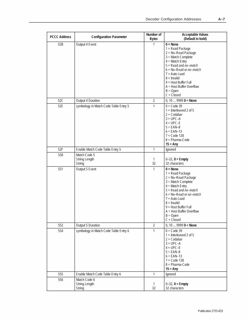
Decoder Configuration Addresses A–7
Publication 2755-833
ÁÁÁÁÁÁÁÁÁÁÁÁÁÁÁÁÁÁÁÁÁÁ
Acceptable Values(Default in bold)
ÁÁÁÁÁÁÁÁ
Number ofBytes
ÁÁÁÁÁÁÁÁÁÁÁÁÁÁÁÁÁÁÁÁÁÁÁÁÁÁ
Configuration ParameterÁÁÁÁÁÁÁÁÁÁ
PCCC AddressÁÁÁÁÁÁÁÁÁÁÁÁÁÁÁÁÁÁÁÁÁÁÁÁÁÁÁÁÁÁÁÁÁÁÁÁÁÁÁÁÁÁÁÁÁÁÁÁÁÁ
52BÁÁÁÁÁÁÁÁÁÁÁÁÁÁÁÁÁÁÁÁÁÁÁÁÁÁÁÁÁÁÁÁÁÁÁÁÁÁÁÁÁÁÁÁÁÁÁÁÁÁÁÁÁÁÁÁÁÁÁÁÁÁÁÁÁÁÁÁÁÁÁÁÁÁÁÁÁÁÁÁÁÁÁÁÁÁÁÁÁÁÁÁÁÁÁÁÁÁÁÁÁÁÁÁÁÁÁÁÁÁÁÁÁÁÁÁÁÁÁÁÁÁÁÁÁÁÁÁÁÁ
Output 4 EventÁÁÁÁÁÁÁÁÁÁÁÁÁÁÁÁÁÁÁÁÁÁÁÁÁÁÁÁÁÁÁÁÁÁÁÁÁÁÁÁ
1ÁÁÁÁÁÁÁÁÁÁÁÁÁÁÁÁÁÁÁÁÁÁÁÁÁÁÁÁÁÁÁÁÁÁÁÁÁÁÁÁÁÁÁÁÁÁÁÁÁÁÁÁÁÁÁÁÁÁÁÁÁÁÁÁÁÁÁÁÁÁÁÁÁÁÁÁÁÁÁÁÁÁÁÁÁÁÁÁÁÁÁÁÁÁÁÁÁÁÁÁÁÁÁÁÁÁÁÁÁÁ
0 = None1 = Read Package2 = No–Read Package3 = Match Complete4 = Match Entry5 = Read and no–match6 = No–Read or no–match7 = Auto Load8 = Invalid9 = Host Buffer FullA = Host Buffer OverflowB = OpenC = Closed
ÁÁÁÁÁÁÁÁÁÁ
52CÁÁÁÁÁÁÁÁÁÁÁÁÁÁÁÁÁÁÁÁÁÁÁÁÁÁ
Output 4 DurationÁÁÁÁÁÁÁÁ
2ÁÁÁÁÁÁÁÁÁÁÁÁÁÁÁÁÁÁÁÁÁÁ
0, 10 ... 9999 0 = NoneÁÁÁÁÁÁÁÁÁÁÁÁÁÁÁÁÁÁÁÁÁÁÁÁÁÁÁÁÁÁÁÁÁÁÁÁÁÁÁÁ
52E ÁÁÁÁÁÁÁÁÁÁÁÁÁÁÁÁÁÁÁÁÁÁÁÁÁÁÁÁÁÁÁÁÁÁÁÁÁÁÁÁÁÁÁÁÁÁÁÁÁÁÁÁÁÁÁÁÁÁÁÁÁÁÁÁÁÁÁÁÁÁÁÁÁÁÁÁÁÁÁÁÁÁÁÁÁÁÁÁÁÁÁÁÁÁÁÁÁÁÁÁÁÁÁÁ
symbology in Match Code Table Entry 5 ÁÁÁÁÁÁÁÁÁÁÁÁÁÁÁÁÁÁÁÁÁÁÁÁÁÁÁÁÁÁÁÁ
1 ÁÁÁÁÁÁÁÁÁÁÁÁÁÁÁÁÁÁÁÁÁÁÁÁÁÁÁÁÁÁÁÁÁÁÁÁÁÁÁÁÁÁÁÁÁÁÁÁÁÁÁÁÁÁÁÁÁÁÁÁÁÁÁÁÁÁÁÁÁÁÁÁÁÁÁÁÁÁÁÁÁÁÁÁÁÁÁÁ
0 = Code 391 = Interleaved 2 of 52 = Codabar3 = UPC–A4 = UPC–E5 = EAN–86 = EAN–137 = Code 1288 = Pharma-Code15 = Any
ÁÁÁÁÁÁÁÁÁÁ
52F ÁÁÁÁÁÁÁÁÁÁÁÁÁÁÁÁÁÁÁÁÁÁÁÁÁÁ
Enable Match Code Table Entry 5 ÁÁÁÁÁÁÁÁ
1 ÁÁÁÁÁÁÁÁÁÁÁÁÁÁÁÁÁÁÁÁÁÁ
IgnoredÁÁÁÁÁÁÁÁÁÁÁÁÁÁÁ
530 ÁÁÁÁÁÁÁÁÁÁÁÁÁÁÁÁÁÁÁÁÁÁÁÁÁÁÁÁÁÁÁÁÁÁÁÁÁÁÁ
Match Code 5String LengthString
ÁÁÁÁÁÁÁÁÁÁÁÁ
132
ÁÁÁÁÁÁÁÁÁÁÁÁÁÁÁÁÁÁÁÁÁÁÁÁÁÁÁÁÁÁÁÁÁ
0–32, 0 = Empty32 characters
ÁÁÁÁÁÁÁÁÁÁÁÁÁÁÁÁÁÁÁÁÁÁÁÁÁÁÁÁÁÁÁÁÁÁÁÁÁÁÁÁÁÁÁÁÁÁÁÁÁÁ
551ÁÁÁÁÁÁÁÁÁÁÁÁÁÁÁÁÁÁÁÁÁÁÁÁÁÁÁÁÁÁÁÁÁÁÁÁÁÁÁÁÁÁÁÁÁÁÁÁÁÁÁÁÁÁÁÁÁÁÁÁÁÁÁÁÁÁÁÁÁÁÁÁÁÁÁÁÁÁÁÁÁÁÁÁÁÁÁÁÁÁÁÁÁÁÁÁÁÁÁÁÁÁÁÁÁÁÁÁÁÁÁÁÁÁÁÁÁÁÁÁÁÁÁÁÁÁÁÁÁÁ
Output 5 EventÁÁÁÁÁÁÁÁÁÁÁÁÁÁÁÁÁÁÁÁÁÁÁÁÁÁÁÁÁÁÁÁÁÁÁÁÁÁÁÁ
1ÁÁÁÁÁÁÁÁÁÁÁÁÁÁÁÁÁÁÁÁÁÁÁÁÁÁÁÁÁÁÁÁÁÁÁÁÁÁÁÁÁÁÁÁÁÁÁÁÁÁÁÁÁÁÁÁÁÁÁÁÁÁÁÁÁÁÁÁÁÁÁÁÁÁÁÁÁÁÁÁÁÁÁÁÁÁÁÁÁÁÁÁÁÁÁÁÁÁÁÁÁÁÁÁÁÁÁÁÁÁ
0 = None1 = Read Package2 = No–Read Package3 = Match Complete4 = Match Entry5 = Read and no–match6 = No–Read or no–match7 = Auto Load8 = Invalid9 = Host Buffer FullA = Host Buffer OverflowB = OpenC = ClosedÁÁÁÁÁ
ÁÁÁÁÁ552ÁÁÁÁÁÁÁÁÁÁÁÁÁÁÁÁÁÁÁÁÁÁÁÁÁÁ
Output 5 DurationÁÁÁÁÁÁÁÁ
2ÁÁÁÁÁÁÁÁÁÁÁÁÁÁÁÁÁÁÁÁÁÁ
0, 10 ... 9999 0 = NoneÁÁÁÁÁÁÁÁÁÁÁÁÁÁÁÁÁÁÁÁÁÁÁÁÁÁÁÁÁÁÁÁÁÁÁÁÁÁÁÁ
554 ÁÁÁÁÁÁÁÁÁÁÁÁÁÁÁÁÁÁÁÁÁÁÁÁÁÁÁÁÁÁÁÁÁÁÁÁÁÁÁÁÁÁÁÁÁÁÁÁÁÁÁÁÁÁÁÁÁÁÁÁÁÁÁÁÁÁÁÁÁÁÁÁÁÁÁÁÁÁÁÁÁÁÁÁÁÁÁÁÁÁÁÁÁÁÁÁÁÁÁÁÁÁÁÁ
symbology in Match Code Table Entry 6 ÁÁÁÁÁÁÁÁÁÁÁÁÁÁÁÁÁÁÁÁÁÁÁÁÁÁÁÁÁÁÁÁ
1 ÁÁÁÁÁÁÁÁÁÁÁÁÁÁÁÁÁÁÁÁÁÁÁÁÁÁÁÁÁÁÁÁÁÁÁÁÁÁÁÁÁÁÁÁÁÁÁÁÁÁÁÁÁÁÁÁÁÁÁÁÁÁÁÁÁÁÁÁÁÁÁÁÁÁÁÁÁÁÁÁÁÁÁÁÁÁÁÁ
0 = Code 391 = Interleaved 2 of 52 = Codabar3 = UPC–A4 = UPC–E5 = EAN–86 = EAN–137 = Code 1288 = Pharma-Code15 = Any
ÁÁÁÁÁÁÁÁÁÁ
555 ÁÁÁÁÁÁÁÁÁÁÁÁÁÁÁÁÁÁÁÁÁÁÁÁÁÁ
Enable Match Code Table Entry 6 ÁÁÁÁÁÁÁÁ
1 ÁÁÁÁÁÁÁÁÁÁÁÁÁÁÁÁÁÁÁÁÁÁ
IgnoredÁÁÁÁÁÁÁÁÁÁÁÁÁÁÁ
556 ÁÁÁÁÁÁÁÁÁÁÁÁÁÁÁÁÁÁÁÁÁÁÁÁÁÁÁÁÁÁÁÁÁÁÁÁÁÁÁ
Match Code 6String LengthString
ÁÁÁÁÁÁÁÁÁÁÁÁ
132
ÁÁÁÁÁÁÁÁÁÁÁÁÁÁÁÁÁÁÁÁÁÁÁÁÁÁÁÁÁÁÁÁÁ
0–32, 0 = Empty32 characters
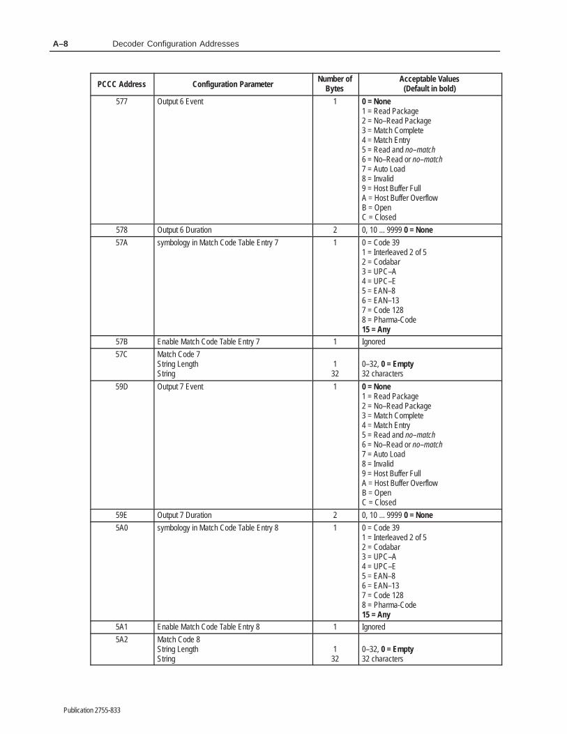
Decoder Configuration AddressesA–8
Publication 2755-833
ÁÁÁÁÁÁÁÁÁÁÁÁÁÁÁÁÁÁÁÁÁÁ
Acceptable Values(Default in bold)
ÁÁÁÁÁÁÁÁÁÁ
Number ofBytes
ÁÁÁÁÁÁÁÁÁÁÁÁÁÁÁÁÁÁÁÁÁÁÁÁ
Configuration ParameterÁÁÁÁÁÁÁÁÁÁ
PCCC AddressÁÁÁÁÁÁÁÁÁÁÁÁÁÁÁÁÁÁÁÁÁÁÁÁÁÁÁÁÁÁÁÁÁÁÁÁÁÁÁÁÁÁÁÁÁÁÁÁÁÁ
577ÁÁÁÁÁÁÁÁÁÁÁÁÁÁÁÁÁÁÁÁÁÁÁÁÁÁÁÁÁÁÁÁÁÁÁÁÁÁÁÁÁÁÁÁÁÁÁÁÁÁÁÁÁÁÁÁÁÁÁÁÁÁÁÁÁÁÁÁÁÁÁÁÁÁÁÁÁÁÁÁÁÁÁÁÁÁÁÁÁÁÁÁÁÁÁÁÁÁÁÁÁÁÁÁÁÁÁÁÁÁÁÁÁÁÁÁÁÁÁÁ
Output 6 EventÁÁÁÁÁÁÁÁÁÁÁÁÁÁÁÁÁÁÁÁÁÁÁÁÁÁÁÁÁÁÁÁÁÁÁÁÁÁÁÁÁÁÁÁÁÁÁÁÁÁ
1ÁÁÁÁÁÁÁÁÁÁÁÁÁÁÁÁÁÁÁÁÁÁÁÁÁÁÁÁÁÁÁÁÁÁÁÁÁÁÁÁÁÁÁÁÁÁÁÁÁÁÁÁÁÁÁÁÁÁÁÁÁÁÁÁÁÁÁÁÁÁÁÁÁÁÁÁÁÁÁÁÁÁÁÁÁÁÁÁÁÁÁÁÁÁÁÁÁÁÁÁÁÁÁÁÁÁÁÁÁÁ
0 = None1 = Read Package2 = No–Read Package3 = Match Complete4 = Match Entry5 = Read and no–match6 = No–Read or no–match7 = Auto Load8 = Invalid9 = Host Buffer FullA = Host Buffer OverflowB = OpenC = Closed
ÁÁÁÁÁÁÁÁÁÁ
578ÁÁÁÁÁÁÁÁÁÁÁÁÁÁÁÁÁÁÁÁÁÁÁÁ
Output 6 DurationÁÁÁÁÁÁÁÁÁÁ
2ÁÁÁÁÁÁÁÁÁÁÁÁÁÁÁÁÁÁÁÁÁÁ
0, 10 ... 9999 0 = NoneÁÁÁÁÁÁÁÁÁÁÁÁÁÁÁÁÁÁÁÁÁÁÁÁÁÁÁÁÁÁÁÁÁÁÁÁÁÁÁÁ
57A ÁÁÁÁÁÁÁÁÁÁÁÁÁÁÁÁÁÁÁÁÁÁÁÁÁÁÁÁÁÁÁÁÁÁÁÁÁÁÁÁÁÁÁÁÁÁÁÁÁÁÁÁÁÁÁÁÁÁÁÁÁÁÁÁÁÁÁÁÁÁÁÁÁÁÁÁÁÁÁÁÁÁÁÁÁÁÁÁÁÁÁÁÁÁÁÁ
symbology in Match Code Table Entry 7 ÁÁÁÁÁÁÁÁÁÁÁÁÁÁÁÁÁÁÁÁÁÁÁÁÁÁÁÁÁÁÁÁÁÁÁÁÁÁÁÁ
1 ÁÁÁÁÁÁÁÁÁÁÁÁÁÁÁÁÁÁÁÁÁÁÁÁÁÁÁÁÁÁÁÁÁÁÁÁÁÁÁÁÁÁÁÁÁÁÁÁÁÁÁÁÁÁÁÁÁÁÁÁÁÁÁÁÁÁÁÁÁÁÁÁÁÁÁÁÁÁÁÁÁÁÁÁÁÁÁÁ
0 = Code 391 = Interleaved 2 of 52 = Codabar3 = UPC–A4 = UPC–E5 = EAN–86 = EAN–137 = Code 1288 = Pharma-Code15 = Any
ÁÁÁÁÁÁÁÁÁÁ
57B ÁÁÁÁÁÁÁÁÁÁÁÁÁÁÁÁÁÁÁÁÁÁÁÁ
Enable Match Code Table Entry 7 ÁÁÁÁÁÁÁÁÁÁ
1 ÁÁÁÁÁÁÁÁÁÁÁÁÁÁÁÁÁÁÁÁÁÁ
IgnoredÁÁÁÁÁÁÁÁÁÁÁÁÁÁÁ
57C ÁÁÁÁÁÁÁÁÁÁÁÁÁÁÁÁÁÁÁÁÁÁÁÁÁÁÁÁÁÁÁÁÁÁÁÁ
Match Code 7String LengthString
ÁÁÁÁÁÁÁÁÁÁÁÁÁÁÁ
132
ÁÁÁÁÁÁÁÁÁÁÁÁÁÁÁÁÁÁÁÁÁÁÁÁÁÁÁÁÁÁÁÁÁ
0–32, 0 = Empty32 characters
ÁÁÁÁÁÁÁÁÁÁÁÁÁÁÁÁÁÁÁÁÁÁÁÁÁÁÁÁÁÁÁÁÁÁÁÁÁÁÁÁÁÁÁÁÁÁÁÁÁÁ
59DÁÁÁÁÁÁÁÁÁÁÁÁÁÁÁÁÁÁÁÁÁÁÁÁÁÁÁÁÁÁÁÁÁÁÁÁÁÁÁÁÁÁÁÁÁÁÁÁÁÁÁÁÁÁÁÁÁÁÁÁÁÁÁÁÁÁÁÁÁÁÁÁÁÁÁÁÁÁÁÁÁÁÁÁÁÁÁÁÁÁÁÁÁÁÁÁÁÁÁÁÁÁÁÁÁÁÁÁÁÁÁÁÁÁÁÁÁÁÁÁ
Output 7 EventÁÁÁÁÁÁÁÁÁÁÁÁÁÁÁÁÁÁÁÁÁÁÁÁÁÁÁÁÁÁÁÁÁÁÁÁÁÁÁÁÁÁÁÁÁÁÁÁÁÁ
1ÁÁÁÁÁÁÁÁÁÁÁÁÁÁÁÁÁÁÁÁÁÁÁÁÁÁÁÁÁÁÁÁÁÁÁÁÁÁÁÁÁÁÁÁÁÁÁÁÁÁÁÁÁÁÁÁÁÁÁÁÁÁÁÁÁÁÁÁÁÁÁÁÁÁÁÁÁÁÁÁÁÁÁÁÁÁÁÁÁÁÁÁÁÁÁÁÁÁÁÁÁÁÁÁÁÁÁÁÁÁ
0 = None1 = Read Package2 = No–Read Package3 = Match Complete4 = Match Entry5 = Read and no–match6 = No–Read or no–match7 = Auto Load8 = Invalid9 = Host Buffer FullA = Host Buffer OverflowB = OpenC = ClosedÁÁÁÁÁ
ÁÁÁÁÁ59EÁÁÁÁÁÁÁÁÁÁÁÁÁÁÁÁÁÁÁÁÁÁÁÁ
Output 7 DurationÁÁÁÁÁÁÁÁÁÁ
2ÁÁÁÁÁÁÁÁÁÁÁÁÁÁÁÁÁÁÁÁÁÁ
0, 10 ... 9999 0 = NoneÁÁÁÁÁÁÁÁÁÁÁÁÁÁÁÁÁÁÁÁÁÁÁÁÁÁÁÁÁÁÁÁÁÁÁÁÁÁÁÁ
5A0 ÁÁÁÁÁÁÁÁÁÁÁÁÁÁÁÁÁÁÁÁÁÁÁÁÁÁÁÁÁÁÁÁÁÁÁÁÁÁÁÁÁÁÁÁÁÁÁÁÁÁÁÁÁÁÁÁÁÁÁÁÁÁÁÁÁÁÁÁÁÁÁÁÁÁÁÁÁÁÁÁÁÁÁÁÁÁÁÁÁÁÁÁÁÁÁÁ
symbology in Match Code Table Entry 8 ÁÁÁÁÁÁÁÁÁÁÁÁÁÁÁÁÁÁÁÁÁÁÁÁÁÁÁÁÁÁÁÁÁÁÁÁÁÁÁÁ
1 ÁÁÁÁÁÁÁÁÁÁÁÁÁÁÁÁÁÁÁÁÁÁÁÁÁÁÁÁÁÁÁÁÁÁÁÁÁÁÁÁÁÁÁÁÁÁÁÁÁÁÁÁÁÁÁÁÁÁÁÁÁÁÁÁÁÁÁÁÁÁÁÁÁÁÁÁÁÁÁÁÁÁÁÁÁÁÁÁ
0 = Code 391 = Interleaved 2 of 52 = Codabar3 = UPC–A4 = UPC–E5 = EAN–86 = EAN–137 = Code 1288 = Pharma-Code15 = Any
ÁÁÁÁÁÁÁÁÁÁ
5A1 ÁÁÁÁÁÁÁÁÁÁÁÁÁÁÁÁÁÁÁÁÁÁÁÁ
Enable Match Code Table Entry 8 ÁÁÁÁÁÁÁÁÁÁ
1 ÁÁÁÁÁÁÁÁÁÁÁÁÁÁÁÁÁÁÁÁÁÁ
IgnoredÁÁÁÁÁÁÁÁÁÁÁÁÁÁÁ
5A2 ÁÁÁÁÁÁÁÁÁÁÁÁÁÁÁÁÁÁÁÁÁÁÁÁÁÁÁÁÁÁÁÁÁÁÁÁ
Match Code 8String LengthString
ÁÁÁÁÁÁÁÁÁÁÁÁÁÁÁ
132
ÁÁÁÁÁÁÁÁÁÁÁÁÁÁÁÁÁÁÁÁÁÁÁÁÁÁÁÁÁÁÁÁÁ
0–32, 0 = Empty32 characters
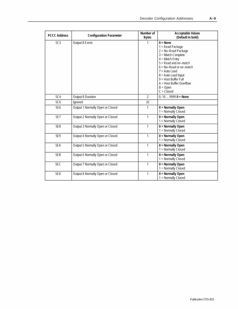
Decoder Configuration Addresses A–9
Publication 2755-833
ÁÁÁÁÁÁÁÁÁÁÁÁÁÁÁÁÁÁÁÁÁÁ
Acceptable Values(Default in bold)
ÁÁÁÁÁÁÁÁ
Number ofBytes
ÁÁÁÁÁÁÁÁÁÁÁÁÁÁÁÁÁÁÁÁÁÁÁÁÁÁ
Configuration ParameterÁÁÁÁÁÁÁÁÁÁ
PCCC AddressÁÁÁÁÁÁÁÁÁÁÁÁÁÁÁÁÁÁÁÁÁÁÁÁÁÁÁÁÁÁÁÁÁÁÁÁÁÁÁÁÁÁÁÁÁÁÁÁÁÁ
5C3ÁÁÁÁÁÁÁÁÁÁÁÁÁÁÁÁÁÁÁÁÁÁÁÁÁÁÁÁÁÁÁÁÁÁÁÁÁÁÁÁÁÁÁÁÁÁÁÁÁÁÁÁÁÁÁÁÁÁÁÁÁÁÁÁÁÁÁÁÁÁÁÁÁÁÁÁÁÁÁÁÁÁÁÁÁÁÁÁÁÁÁÁÁÁÁÁÁÁÁÁÁÁÁÁÁÁÁÁÁÁÁÁÁÁÁÁÁÁÁÁÁÁÁÁÁÁÁÁÁÁ
Output 8 EventÁÁÁÁÁÁÁÁÁÁÁÁÁÁÁÁÁÁÁÁÁÁÁÁÁÁÁÁÁÁÁÁÁÁÁÁÁÁÁÁ
1ÁÁÁÁÁÁÁÁÁÁÁÁÁÁÁÁÁÁÁÁÁÁÁÁÁÁÁÁÁÁÁÁÁÁÁÁÁÁÁÁÁÁÁÁÁÁÁÁÁÁÁÁÁÁÁÁÁÁÁÁÁÁÁÁÁÁÁÁÁÁÁÁÁÁÁÁÁÁÁÁÁÁÁÁÁÁÁÁÁÁÁÁÁÁÁÁÁÁÁÁÁÁÁÁÁÁÁÁÁÁ
0 = None1 = Read Package2 = No–Read Package3 = Match Complete4 = Match Entry5 = Read and no–match6 = No–Read or no–match7 = Auto Load8 = Auto Load Input9 = Host Buffer FullA = Host Buffer OverflowB = OpenC = Closed
ÁÁÁÁÁÁÁÁÁÁ
5C4ÁÁÁÁÁÁÁÁÁÁÁÁÁÁÁÁÁÁÁÁÁÁÁÁÁÁ
Output 8 DurationÁÁÁÁÁÁÁÁ
2ÁÁÁÁÁÁÁÁÁÁÁÁÁÁÁÁÁÁÁÁÁÁ
0, 10 ... 9999 0 = NoneÁÁÁÁÁÁÁÁÁÁ
5C6 ÁÁÁÁÁÁÁÁÁÁÁÁÁÁÁÁÁÁÁÁÁÁÁÁÁÁ
Ignored ÁÁÁÁÁÁÁÁ
32 ÁÁÁÁÁÁÁÁÁÁÁÁÁÁÁÁÁÁÁÁÁÁÁÁÁÁÁ
ÁÁÁÁÁÁÁÁÁÁ
5E6 ÁÁÁÁÁÁÁÁÁÁÁÁÁÁÁÁÁÁÁÁÁÁÁÁÁÁÁÁÁÁÁÁÁÁÁÁÁÁÁ
Output 1 Normally Open or Closed ÁÁÁÁÁÁÁÁÁÁÁÁ
1 ÁÁÁÁÁÁÁÁÁÁÁÁÁÁÁÁÁÁÁÁÁÁÁÁÁÁÁÁÁÁÁÁÁ
0 = Normally Open1 = Normally Closed
ÁÁÁÁÁÁÁÁÁÁ
5E7 ÁÁÁÁÁÁÁÁÁÁÁÁÁÁÁÁÁÁÁÁÁÁÁÁÁÁ
Output 2 Normally Open or Closed ÁÁÁÁÁÁÁÁ
1 ÁÁÁÁÁÁÁÁÁÁÁÁÁÁÁÁÁÁÁÁÁÁ
0 = Normally Open1 = Normally Closed
ÁÁÁÁÁÁÁÁÁÁÁÁÁÁÁ
5E8 ÁÁÁÁÁÁÁÁÁÁÁÁÁÁÁÁÁÁÁÁÁÁÁÁÁÁÁÁÁÁÁÁÁÁÁÁÁÁÁ
Output 3 Normally Open or Closed ÁÁÁÁÁÁÁÁÁÁÁÁ
1 ÁÁÁÁÁÁÁÁÁÁÁÁÁÁÁÁÁÁÁÁÁÁÁÁÁÁÁÁÁÁÁÁÁ
0 = Normally Open1 = Normally Closed
ÁÁÁÁÁÁÁÁÁÁ
5E9 ÁÁÁÁÁÁÁÁÁÁÁÁÁÁÁÁÁÁÁÁÁÁÁÁÁÁ
Output 4 Normally Open or Closed ÁÁÁÁÁÁÁÁ
1 ÁÁÁÁÁÁÁÁÁÁÁÁÁÁÁÁÁÁÁÁÁÁ
0 = Normally Open1 = Normally ClosedÁÁÁÁÁ
ÁÁÁÁÁÁÁÁÁÁ
5EAÁÁÁÁÁÁÁÁÁÁÁÁÁÁÁÁÁÁÁÁÁÁÁÁÁÁÁÁÁÁÁÁÁÁÁÁÁÁÁ
Output 5 Normally Open or ClosedÁÁÁÁÁÁÁÁÁÁÁÁ
1ÁÁÁÁÁÁÁÁÁÁÁÁÁÁÁÁÁÁÁÁÁÁÁÁÁÁÁÁÁÁÁÁÁ
0 = Normally Open1 = Normally Closed
ÁÁÁÁÁÁÁÁÁÁ
5EB ÁÁÁÁÁÁÁÁÁÁÁÁÁÁÁÁÁÁÁÁÁÁÁÁÁÁ
Output 6 Normally Open or Closed ÁÁÁÁÁÁÁÁ
1 ÁÁÁÁÁÁÁÁÁÁÁÁÁÁÁÁÁÁÁÁÁÁ
0 = Normally Open1 = Normally ClosedÁÁÁÁÁ
ÁÁÁÁÁÁÁÁÁÁ
5ECÁÁÁÁÁÁÁÁÁÁÁÁÁÁÁÁÁÁÁÁÁÁÁÁÁÁÁÁÁÁÁÁÁÁÁÁÁÁÁ
Output 7 Normally Open or ClosedÁÁÁÁÁÁÁÁÁÁÁÁ
1ÁÁÁÁÁÁÁÁÁÁÁÁÁÁÁÁÁÁÁÁÁÁÁÁÁÁÁÁÁÁÁÁÁ
0 = Normally Open1 = Normally Closed
ÁÁÁÁÁÁÁÁÁÁÁÁÁÁÁ
5ED ÁÁÁÁÁÁÁÁÁÁÁÁÁÁÁÁÁÁÁÁÁÁÁÁÁÁÁÁÁÁÁÁÁÁÁÁÁÁÁ
Output 8 Normally Open or Closed ÁÁÁÁÁÁÁÁÁÁÁÁ
1 ÁÁÁÁÁÁÁÁÁÁÁÁÁÁÁÁÁÁÁÁÁÁÁÁÁÁÁÁÁÁÁÁÁ
0 = Normally Open1 = Normally Closed

Decoder Configuration AddressesA–10
Publication 2755-833
Decoder Function or Command Addresses
Refer to Chapter 16 for additional information on the use of thesecommands and functions.
ÁÁÁÁÁÁÁÁ
AddressÁÁÁÁÁÁÁÁÁÁÁÁÁÁÁÁÁÁÁÁÁÁÁÁÁÁÁÁÁÁÁÁÁÁÁÁ
Command
ÁÁÁÁ0600H ÁÁÁÁÁÁÁÁÁÁÁÁÁÁÁÁÁÁClear package countsÁÁÁÁÁÁÁÁ0604H
ÁÁÁÁÁÁÁÁÁÁÁÁÁÁÁÁÁÁÁÁÁÁÁÁÁÁÁÁÁÁÁÁÁÁÁÁClear primary count 1ÁÁÁÁ
ÁÁÁÁ0608HÁÁÁÁÁÁÁÁÁÁÁÁÁÁÁÁÁÁÁÁÁÁÁÁÁÁÁÁÁÁÁÁÁÁÁÁClear primary count 2ÁÁÁÁ
ÁÁÁÁ060CHÁÁÁÁÁÁÁÁÁÁÁÁÁÁÁÁÁÁÁÁÁÁÁÁÁÁÁÁÁÁÁÁÁÁÁÁ
Clear primary count 3ÁÁÁÁÁÁÁÁ
0610H ÁÁÁÁÁÁÁÁÁÁÁÁÁÁÁÁÁÁÁÁÁÁÁÁÁÁÁÁÁÁÁÁÁÁÁÁ
Clear primary count 4ÁÁÁÁÁÁÁÁ
0614H ÁÁÁÁÁÁÁÁÁÁÁÁÁÁÁÁÁÁÁÁÁÁÁÁÁÁÁÁÁÁÁÁÁÁÁÁ
Clear primary count 5ÁÁÁÁÁÁÁÁ
0618H ÁÁÁÁÁÁÁÁÁÁÁÁÁÁÁÁÁÁÁÁÁÁÁÁÁÁÁÁÁÁÁÁÁÁÁÁ
Clear primary count 6
ÁÁÁÁÁÁÁÁ
061CHÁÁÁÁÁÁÁÁÁÁÁÁÁÁÁÁÁÁÁÁÁÁÁÁÁÁÁÁÁÁÁÁÁÁÁÁ
Clear primary count 7
ÁÁÁÁÁÁÁÁ
0620H ÁÁÁÁÁÁÁÁÁÁÁÁÁÁÁÁÁÁÁÁÁÁÁÁÁÁÁÁÁÁÁÁÁÁÁÁ
Clear primary count 8
ÁÁÁÁ0624H ÁÁÁÁÁÁÁÁÁÁÁÁÁÁÁÁÁÁClear symbols not read countÁÁÁÁÁÁÁÁ0630H
ÁÁÁÁÁÁÁÁÁÁÁÁÁÁÁÁÁÁÁÁÁÁÁÁÁÁÁÁÁÁÁÁÁÁÁÁClear all primary countsÁÁÁÁ
ÁÁÁÁ0631HÁÁÁÁÁÁÁÁÁÁÁÁÁÁÁÁÁÁÁÁÁÁÁÁÁÁÁÁÁÁÁÁÁÁÁÁClear all primary counts and symbols not read countÁÁÁÁ
ÁÁÁÁ0632HÁÁÁÁÁÁÁÁÁÁÁÁÁÁÁÁÁÁÁÁÁÁÁÁÁÁÁÁÁÁÁÁÁÁÁÁ
Save configuration to Storage Memory and restartÁÁÁÁÁÁÁÁ
0633H ÁÁÁÁÁÁÁÁÁÁÁÁÁÁÁÁÁÁÁÁÁÁÁÁÁÁÁÁÁÁÁÁÁÁÁÁ
Set configuration to default valuesÁÁÁÁÁÁÁÁ
0634H ÁÁÁÁÁÁÁÁÁÁÁÁÁÁÁÁÁÁÁÁÁÁÁÁÁÁÁÁÁÁÁÁÁÁÁÁ
Start scan AÁÁÁÁÁÁÁÁ
0635H ÁÁÁÁÁÁÁÁÁÁÁÁÁÁÁÁÁÁÁÁÁÁÁÁÁÁÁÁÁÁÁÁÁÁÁÁ
Stop scan A
ÁÁÁÁÁÁÁÁ
0636H ÁÁÁÁÁÁÁÁÁÁÁÁÁÁÁÁÁÁÁÁÁÁÁÁÁÁÁÁÁÁÁÁÁÁÁÁ
Flush current packet from host buffer
ÁÁÁÁÁÁÁÁ
0637H ÁÁÁÁÁÁÁÁÁÁÁÁÁÁÁÁÁÁÁÁÁÁÁÁÁÁÁÁÁÁÁÁÁÁÁÁ
Restart decoder
ÁÁÁÁÁÁÁÁ
0640H ÁÁÁÁÁÁÁÁÁÁÁÁÁÁÁÁÁÁÁÁÁÁÁÁÁÁÁÁÁÁÁÁÁÁÁÁ
Send repeat read
ÁÁÁÁ0641H ÁÁÁÁÁÁÁÁÁÁÁÁÁÁÁÁÁÁCancel repeat readÁÁÁÁÁÁÁÁ0642H
ÁÁÁÁÁÁÁÁÁÁÁÁÁÁÁÁÁÁÁÁÁÁÁÁÁÁÁÁÁÁÁÁÁÁÁÁClear all Extended countsÁÁÁÁ
ÁÁÁÁ0643HÁÁÁÁÁÁÁÁÁÁÁÁÁÁÁÁÁÁÁÁÁÁÁÁÁÁÁÁÁÁÁÁÁÁÁÁ
Auto–Load StartÁÁÁÁÁÁÁÁ
0644H ÁÁÁÁÁÁÁÁÁÁÁÁÁÁÁÁÁÁÁÁÁÁÁÁÁÁÁÁÁÁÁÁÁÁÁÁ
Auto–load EndÁÁÁÁÁÁÁÁ
0650H ÁÁÁÁÁÁÁÁÁÁÁÁÁÁÁÁÁÁÁÁÁÁÁÁÁÁÁÁÁÁÁÁÁÁÁÁ
Hold output 1 open➀
ÁÁÁÁÁÁÁÁ
0651H ÁÁÁÁÁÁÁÁÁÁÁÁÁÁÁÁÁÁÁÁÁÁÁÁÁÁÁÁÁÁÁÁÁÁÁÁ
Hold output 2 open➀
ÁÁÁÁÁÁÁÁ
0652H ÁÁÁÁÁÁÁÁÁÁÁÁÁÁÁÁÁÁÁÁÁÁÁÁÁÁÁÁÁÁÁÁÁÁÁÁ
Hold output 3 open➀
ÁÁÁÁÁÁÁÁ
0653H ÁÁÁÁÁÁÁÁÁÁÁÁÁÁÁÁÁÁÁÁÁÁÁÁÁÁÁÁÁÁÁÁÁÁÁÁ
Hold output 4 open➀
ÁÁÁÁÁÁÁÁ
0654H ÁÁÁÁÁÁÁÁÁÁÁÁÁÁÁÁÁÁÁÁÁÁÁÁÁÁÁÁÁÁÁÁÁÁÁÁ
Hold output 5 open➀
ÁÁÁÁÁÁÁÁ
0655H ÁÁÁÁÁÁÁÁÁÁÁÁÁÁÁÁÁÁÁÁÁÁÁÁÁÁÁÁÁÁÁÁÁÁÁÁ
Hold output 6 open➀
ÁÁÁÁÁÁÁÁ
0656H ÁÁÁÁÁÁÁÁÁÁÁÁÁÁÁÁÁÁÁÁÁÁÁÁÁÁÁÁÁÁÁÁÁÁÁÁ
Hold output 7 open➀
ÁÁÁÁÁÁÁÁ
0657H ÁÁÁÁÁÁÁÁÁÁÁÁÁÁÁÁÁÁÁÁÁÁÁÁÁÁÁÁÁÁÁÁÁÁÁÁ
Hold output 8 open➀
ÁÁÁÁÁÁÁÁ
0660HÁÁÁÁÁÁÁÁÁÁÁÁÁÁÁÁÁÁÁÁÁÁÁÁÁÁÁÁÁÁÁÁÁÁÁÁ
Hold output 1 closed➀
ÁÁÁÁÁÁÁÁ
0661HÁÁÁÁÁÁÁÁÁÁÁÁÁÁÁÁÁÁÁÁÁÁÁÁÁÁÁÁÁÁÁÁÁÁÁÁ
Hold output 2 closed➀
➀ The AUX port supports a terminal for either configuring the decoder or for manentry. For information on use of the AUX port for manual data entry, consult Cha

Decoder Configuration Addresses A–11
Publication 2755-833
ÁÁÁÁÁÁÁÁ
AddressÁÁÁÁÁÁÁÁÁÁÁÁÁÁÁÁÁÁÁÁÁÁÁÁÁÁÁÁÁÁÁÁÁÁÁÁ
Command
ÁÁÁÁÁÁÁÁ
0662HÁÁÁÁÁÁÁÁÁÁÁÁÁÁÁÁÁÁÁÁÁÁÁÁÁÁÁÁÁÁÁÁÁÁÁÁ
Hold output 3 closed➀
ÁÁÁÁÁÁÁÁ
0663HÁÁÁÁÁÁÁÁÁÁÁÁÁÁÁÁÁÁÁÁÁÁÁÁÁÁÁÁÁÁÁÁÁÁÁÁ
Hold output 4 closed➀
ÁÁÁÁÁÁÁÁ
0664HÁÁÁÁÁÁÁÁÁÁÁÁÁÁÁÁÁÁÁÁÁÁÁÁÁÁÁÁÁÁÁÁÁÁÁÁ
Hold output 5 closed➀
ÁÁÁÁÁÁÁÁ
0665HÁÁÁÁÁÁÁÁÁÁÁÁÁÁÁÁÁÁÁÁÁÁÁÁÁÁÁÁÁÁÁÁÁÁÁÁ
Hold output 6 closed➀
ÁÁÁÁÁÁÁÁ
0666HÁÁÁÁÁÁÁÁÁÁÁÁÁÁÁÁÁÁÁÁÁÁÁÁÁÁÁÁÁÁÁÁÁÁÁÁ
Hold output 7 closed➀
ÁÁÁÁÁÁÁÁ
0667HÁÁÁÁÁÁÁÁÁÁÁÁÁÁÁÁÁÁÁÁÁÁÁÁÁÁÁÁÁÁÁÁÁÁÁÁ
Hold output 8 closed➀
ÁÁÁÁÁÁÁÁ
0668HÁÁÁÁÁÁÁÁÁÁÁÁÁÁÁÁÁÁÁÁÁÁÁÁÁÁÁÁÁÁÁÁÁÁÁÁ
Start Scanner B Trigger
ÁÁÁÁ0669HÁÁÁÁÁÁÁÁÁÁÁÁÁÁÁÁÁÁStop Scanner B Trigger
Pharma–Code Configuration 0700H–0725H
The decoder shall use the existing ’set match table symbology type’command with a value of 9 to set the match table symbology type toPHARMA.
The table below shows the mapping between the PCCC HostCommands and the parameters described in the PHARMA–CODE
CONFIGURATION PARAMETERS section.
ÁÁÁÁÁÁÁÁÁÁÁÁ
PCCC Address ÁÁÁÁÁÁÁÁÁÁÁÁÁÁÁÁÁÁÁÁÁÁÁÁ
Configuration Parameter ÁÁÁÁÁÁÁÁ
Number ofBytesÁÁÁÁÁÁÁÁÁÁÁÁÁÁÁÁÁÁÁÁ
Acceptable Values(Default in bold)ÁÁÁÁÁÁ
ÁÁÁÁÁÁÁÁÁÁÁÁ
700HÁÁÁÁÁÁÁÁÁÁÁÁÁÁÁÁÁÁÁÁÁÁÁÁÁÁÁÁÁÁÁÁÁÁÁÁ
enable Pharma–CodeÁÁÁÁÁÁÁÁÁÁÁÁ
1ÁÁÁÁÁÁÁÁÁÁÁÁÁÁÁÁÁÁÁÁÁÁÁÁÁÁÁÁÁÁ
0 = No1 = Yes
ÁÁÁÁÁÁÁÁÁÁÁÁÁÁÁÁÁÁÁÁÁÁÁÁÁÁÁÁÁÁ
701H ÁÁÁÁÁÁÁÁÁÁÁÁÁÁÁÁÁÁÁÁÁÁÁÁÁÁÁÁÁÁÁÁÁÁÁÁÁÁÁÁÁÁÁÁÁÁÁÁÁÁÁÁÁÁÁÁÁÁÁÁ
decode direction ÁÁÁÁÁÁÁÁÁÁÁÁÁÁÁÁÁÁÁÁ
1 ÁÁÁÁÁÁÁÁÁÁÁÁÁÁÁÁÁÁÁÁÁÁÁÁÁÁÁÁÁÁÁÁÁÁÁÁÁÁÁÁÁÁÁÁÁÁÁÁÁÁ
0 = Forward1 = Reverse2 = Forward A Reverse B3 = Reverse A Forward B
ÁÁÁÁÁÁÁÁÁÁÁÁ
702H ÁÁÁÁÁÁÁÁÁÁÁÁÁÁÁÁÁÁÁÁÁÁÁÁquiet zone ratio ÁÁÁÁ
ÁÁÁÁ1 ÁÁÁÁÁÁÁÁÁÁÁÁÁÁÁÁÁÁÁÁ
4 – 10, 5 = Default, 0 = Use DefaultÁÁÁÁÁÁÁÁÁÁÁÁÁÁÁÁÁÁ
703H ÁÁÁÁÁÁÁÁÁÁÁÁÁÁÁÁÁÁÁÁÁÁÁÁÁÁÁÁÁÁÁÁÁÁÁÁ
space tolerance ÁÁÁÁÁÁÁÁÁÁÁÁ
1 ÁÁÁÁÁÁÁÁÁÁÁÁÁÁÁÁÁÁÁÁÁÁÁÁÁÁÁÁÁÁ
0 = Ignore5 to 40, 15
ÁÁÁÁÁÁÁÁÁÁÁÁ
704H ÁÁÁÁÁÁÁÁÁÁÁÁÁÁÁÁÁÁÁÁÁÁÁÁbar tolerance ÁÁÁÁ
ÁÁÁÁ1 ÁÁÁÁÁÁÁÁÁÁÁÁÁÁÁÁÁÁÁÁ
0 = Ignore5 to 40, 15
ÁÁÁÁÁÁÁÁÁÁÁÁ
705HÁÁÁÁÁÁÁÁÁÁÁÁÁÁÁÁÁÁÁÁÁÁÁÁminimum number of bars
ÁÁÁÁÁÁÁÁ
1ÁÁÁÁÁÁÁÁÁÁÁÁÁÁÁÁÁÁÁÁ
3 to 12, 5ÁÁÁÁÁÁÁÁÁÁÁÁÁÁÁÁÁÁ
706H ÁÁÁÁÁÁÁÁÁÁÁÁÁÁÁÁÁÁÁÁÁÁÁÁÁÁÁÁÁÁÁÁÁÁÁÁ
wide to narrow bar ratio ÁÁÁÁÁÁÁÁÁÁÁÁ
1 ÁÁÁÁÁÁÁÁÁÁÁÁÁÁÁÁÁÁÁÁÁÁÁÁÁÁÁÁÁÁ
0 = Midrange2 to 4
ÁÁÁÁÁÁÁÁÁÁÁÁ
707H ÁÁÁÁÁÁÁÁÁÁÁÁÁÁÁÁÁÁÁÁÁÁÁÁcode verification list entry 1 ÁÁÁÁ
ÁÁÁÁ2 ÁÁÁÁÁÁÁÁÁÁÁÁÁÁÁÁÁÁÁÁ
0 = none7 to 8190
ÁÁÁÁÁÁÁÁÁÁÁÁÁÁÁÁÁÁ
709H to 725HÁÁÁÁÁÁÁÁÁÁÁÁÁÁÁÁÁÁÁÁÁÁÁÁÁÁÁÁÁÁÁÁÁÁÁÁ
code verification list entry 2 through 16ÁÁÁÁÁÁÁÁÁÁÁÁ
2 bytes perentry
ÁÁÁÁÁÁÁÁÁÁÁÁÁÁÁÁÁÁÁÁÁÁÁÁÁÁÁÁÁÁ
0 = none7 to 8190
➀ The AUX port supports a terminal for either configuring the decoder or for manentry. For information on use of the AUX port for manual data entry, consult Cha

Decoder Configuration AddressesA–12
Publication 2755-833
Series B Configuration Parameters 0900H–0901H
ÁÁÁÁÁÁÁÁÁÁÁÁÁÁÁ
PCCC AddressÁÁÁÁÁÁÁÁÁÁÁÁÁÁÁÁÁÁÁÁÁÁÁÁÁÁÁÁÁÁÁÁÁÁÁÁ
Configuration ParameterÁÁÁÁÁÁÁÁÁÁÁÁÁÁÁ
Number ofBytes
ÁÁÁÁÁÁÁÁÁÁÁÁÁÁÁÁÁÁÁÁÁÁÁÁÁÁÁÁÁÁ
Acceptable Values(Default in bold)
ÁÁÁÁÁÁÁÁÁÁÁÁÁÁÁ
900H ÁÁÁÁÁÁÁÁÁÁÁÁÁÁÁÁÁÁÁÁÁÁÁÁÁÁÁÁÁÁÁÁÁÁÁÁ
write text message to AUX/LCDstring lengthstring
ÁÁÁÁÁÁÁÁÁÁÁÁÁÁÁ
1128
ÁÁÁÁÁÁÁÁÁÁÁÁÁÁÁÁÁÁÁÁÁÁÁÁÁÁÁÁÁÁ
0 – 128, 0 = Empty128 characters
ÁÁÁÁÁÁÁÁÁÁÁÁÁÁÁÁÁÁÁÁ
901H ÁÁÁÁÁÁÁÁÁÁÁÁÁÁÁÁÁÁÁÁÁÁÁÁÁÁÁÁÁÁÁÁÁÁÁÁÁÁÁÁÁÁÁÁÁÁÁÁ
write text message to AUX/LCD and enable keyboard entrystring lengthstring
ÁÁÁÁÁÁÁÁÁÁÁÁÁÁÁÁÁÁÁÁ
1128
ÁÁÁÁÁÁÁÁÁÁÁÁÁÁÁÁÁÁÁÁÁÁÁÁÁÁÁÁÁÁÁÁÁÁÁÁÁÁÁÁ
0 – 128, 0 = Empty128 characters
Series B Configuration Parameters 0E00H–0EFFH
ÁÁÁÁÁÁÁÁÁÁÁÁÁÁÁ
PCCC AddressÁÁÁÁÁÁÁÁÁÁÁÁÁÁÁÁÁÁÁÁÁÁÁÁÁÁÁÁÁÁÁÁÁÁÁÁ
Configuration ParameterÁÁÁÁÁÁÁÁÁÁÁÁÁÁÁ
Number ofBytes
ÁÁÁÁÁÁÁÁÁÁÁÁÁÁÁÁÁÁÁÁÁÁÁÁÁÁÁÁÁÁ
Acceptable Values(Default in bold)
ÁÁÁÁÁÁÁÁÁÁ
E10 ÁÁÁÁÁÁÁÁÁÁÁÁÁÁÁÁÁÁÁÁÁÁÁÁ
Verify Interleaved 2 of 5 guard bars ÁÁÁÁÁÁÁÁÁÁ
1 ÁÁÁÁÁÁÁÁÁÁÁÁÁÁÁÁÁÁÁÁ
0 = No1 = YesÁÁÁÁÁ
ÁÁÁÁÁÁÁÁÁÁÁÁÁÁÁ
E11ÁÁÁÁÁÁÁÁÁÁÁÁÁÁÁÁÁÁÁÁÁÁÁÁÁÁÁÁÁÁÁÁÁÁÁÁÁÁÁÁÁÁÁÁÁÁÁÁ
Scanner source of event 1ÁÁÁÁÁÁÁÁÁÁÁÁÁÁÁÁÁÁÁÁ
1ÁÁÁÁÁÁÁÁÁÁÁÁÁÁÁÁÁÁÁÁÁÁÁÁÁÁÁÁÁÁÁÁÁÁÁÁÁÁÁÁ
1 = Scanner A2 = Scanner B3 = A|B5 = A–BÁÁÁÁÁ
ÁÁÁÁÁÁÁÁÁÁÁÁÁÁÁ
E12ÁÁÁÁÁÁÁÁÁÁÁÁÁÁÁÁÁÁÁÁÁÁÁÁÁÁÁÁÁÁÁÁÁÁÁÁÁÁÁÁÁÁÁÁÁÁÁÁ
Scanner source of event 2ÁÁÁÁÁÁÁÁÁÁÁÁÁÁÁÁÁÁÁÁ
1ÁÁÁÁÁÁÁÁÁÁÁÁÁÁÁÁÁÁÁÁÁÁÁÁÁÁÁÁÁÁÁÁÁÁÁÁÁÁÁÁ
1 = Scanner A2 = Scanner B3 = A|B5 = A–BÁÁÁÁÁ
ÁÁÁÁÁÁÁÁÁÁÁÁÁÁÁ
E13ÁÁÁÁÁÁÁÁÁÁÁÁÁÁÁÁÁÁÁÁÁÁÁÁÁÁÁÁÁÁÁÁÁÁÁÁÁÁÁÁÁÁÁÁÁÁÁÁ
Scanner source of event 3ÁÁÁÁÁÁÁÁÁÁÁÁÁÁÁÁÁÁÁÁ
1ÁÁÁÁÁÁÁÁÁÁÁÁÁÁÁÁÁÁÁÁÁÁÁÁÁÁÁÁÁÁÁÁÁÁÁÁÁÁÁÁ
1 = Scanner A2 = Scanner B3 = A|B5 = A–B
ÁÁÁÁÁÁÁÁÁÁÁÁÁÁÁÁÁÁÁÁ
E14 ÁÁÁÁÁÁÁÁÁÁÁÁÁÁÁÁÁÁÁÁÁÁÁÁÁÁÁÁÁÁÁÁÁÁÁÁÁÁÁÁÁÁÁÁÁÁÁÁ
Scanner source of event 4 ÁÁÁÁÁÁÁÁÁÁÁÁÁÁÁÁÁÁÁÁ
1 ÁÁÁÁÁÁÁÁÁÁÁÁÁÁÁÁÁÁÁÁÁÁÁÁÁÁÁÁÁÁÁÁÁÁÁÁÁÁÁÁ
1 = Scanner A2 = Scanner B3 = A|B5 = A–B
ÁÁÁÁÁÁÁÁÁÁÁÁÁÁÁÁÁÁÁÁ
E15 ÁÁÁÁÁÁÁÁÁÁÁÁÁÁÁÁÁÁÁÁÁÁÁÁÁÁÁÁÁÁÁÁÁÁÁÁÁÁÁÁÁÁÁÁÁÁÁÁ
Scanner source of event 5 ÁÁÁÁÁÁÁÁÁÁÁÁÁÁÁÁÁÁÁÁ
1 ÁÁÁÁÁÁÁÁÁÁÁÁÁÁÁÁÁÁÁÁÁÁÁÁÁÁÁÁÁÁÁÁÁÁÁÁÁÁÁÁ
1 = Scanner A2 = Scanner B3 = A|B5 = A–B
ÁÁÁÁÁÁÁÁÁÁÁÁÁÁÁÁÁÁÁÁ
E16 ÁÁÁÁÁÁÁÁÁÁÁÁÁÁÁÁÁÁÁÁÁÁÁÁÁÁÁÁÁÁÁÁÁÁÁÁÁÁÁÁÁÁÁÁÁÁÁÁ
Scanner source of event 6 ÁÁÁÁÁÁÁÁÁÁÁÁÁÁÁÁÁÁÁÁ
1 ÁÁÁÁÁÁÁÁÁÁÁÁÁÁÁÁÁÁÁÁÁÁÁÁÁÁÁÁÁÁÁÁÁÁÁÁÁÁÁÁ
1 = Scanner A2 = Scanner B3 = A|B5 = A–B
ÁÁÁÁÁÁÁÁÁÁÁÁÁÁÁÁÁÁÁÁ
E17 ÁÁÁÁÁÁÁÁÁÁÁÁÁÁÁÁÁÁÁÁÁÁÁÁÁÁÁÁÁÁÁÁÁÁÁÁÁÁÁÁÁÁÁÁÁÁÁÁ
Scanner source of event 7 ÁÁÁÁÁÁÁÁÁÁÁÁÁÁÁÁÁÁÁÁ
1 ÁÁÁÁÁÁÁÁÁÁÁÁÁÁÁÁÁÁÁÁÁÁÁÁÁÁÁÁÁÁÁÁÁÁÁÁÁÁÁÁ
1 = Scanner A2 = Scanner B3 = A|B5 = A–B
ÁÁÁÁÁÁÁÁÁÁÁÁÁÁÁÁÁÁÁÁ
E18 ÁÁÁÁÁÁÁÁÁÁÁÁÁÁÁÁÁÁÁÁÁÁÁÁÁÁÁÁÁÁÁÁÁÁÁÁÁÁÁÁÁÁÁÁÁÁÁÁ
Scanner source of event 8 ÁÁÁÁÁÁÁÁÁÁÁÁÁÁÁÁÁÁÁÁ
1 ÁÁÁÁÁÁÁÁÁÁÁÁÁÁÁÁÁÁÁÁÁÁÁÁÁÁÁÁÁÁÁÁÁÁÁÁÁÁÁÁ
1 = Scanner A2 = Scanner B3 = A|B5 = A–B
ÁÁÁÁÁÁÁÁÁÁÁÁÁÁÁ
E19 ÁÁÁÁÁÁÁÁÁÁÁÁÁÁÁÁÁÁÁÁÁÁÁÁÁÁÁÁÁÁÁÁÁÁÁÁ
Laser B On mode ÁÁÁÁÁÁÁÁÁÁÁÁÁÁÁ
1 ÁÁÁÁÁÁÁÁÁÁÁÁÁÁÁÁÁÁÁÁÁÁÁÁÁÁÁÁÁÁ
0 = Continuous1 = Triggered2 = Off
ÁÁÁÁÁÁÁÁÁÁ
E1A ÁÁÁÁÁÁÁÁÁÁÁÁÁÁÁÁÁÁÁÁÁÁÁÁ
Set number of Fields in host_message ÁÁÁÁÁÁÁÁÁÁ
1 ÁÁÁÁÁÁÁÁÁÁÁÁÁÁÁÁÁÁÁÁ
0 – 16, 0 = ALL
ÁÁÁÁÁÁÁÁÁÁ
E1B ÁÁÁÁÁÁÁÁÁÁÁÁÁÁÁÁÁÁÁÁÁÁÁÁ
FNC1 Character ÁÁÁÁÁÁÁÁÁÁ
1 ÁÁÁÁÁÁÁÁÁÁÁÁÁÁÁÁÁÁÁÁ
00–FFh, 00 = Ignore
ÁÁÁÁÁÁÁÁÁÁ
E1C ÁÁÁÁÁÁÁÁÁÁÁÁÁÁÁÁÁÁÁÁÁÁÁÁ
Quiet Zone Ratio ÁÁÁÁÁÁÁÁÁÁ
1 ÁÁÁÁÁÁÁÁÁÁÁÁÁÁÁÁÁÁÁÁ
4–10, 5 = Default, 0 = Use Default

Decoder Configuration Addresses A–13
Publication 2755-833
ÁÁÁÁÁÁÁÁÁÁÁÁÁÁÁÁÁÁÁÁ
Acceptable Values(Default in bold)
ÁÁÁÁÁÁÁÁ
Number ofBytes
ÁÁÁÁÁÁÁÁÁÁÁÁÁÁÁÁÁÁÁÁÁÁÁÁ
Configuration ParameterÁÁÁÁÁÁÁÁÁÁÁÁ
PCCC AddressÁÁÁÁÁÁÁÁÁÁÁÁ
E1DÁÁÁÁÁÁÁÁÁÁÁÁÁÁÁÁÁÁÁÁÁÁÁÁScanner B Start Scan Character
ÁÁÁÁÁÁÁÁ
1ÁÁÁÁÁÁÁÁÁÁÁÁÁÁÁÁÁÁÁÁ
ASCII 0 – 255, 255 = NoneÁÁÁÁÁÁÁÁÁÁÁÁ
E1E ÁÁÁÁÁÁÁÁÁÁÁÁÁÁÁÁÁÁÁÁÁÁÁÁScanner B Stop Scan Character ÁÁÁÁ
ÁÁÁÁ1 ÁÁÁÁÁÁÁÁÁÁÁÁÁÁÁÁÁÁÁÁ
ASCII 0 – 255, 255 = NoneÁÁÁÁÁÁÁÁÁÁÁÁÁÁÁÁÁÁ
E1F ÁÁÁÁÁÁÁÁÁÁÁÁÁÁÁÁÁÁÁÁÁÁÁÁÁÁÁÁÁÁÁÁÁÁÁÁ
Extended Match Set 1 (1 – 16) ÁÁÁÁÁÁÁÁÁÁÁÁ
1 ÁÁÁÁÁÁÁÁÁÁÁÁÁÁÁÁÁÁÁÁÁÁÁÁÁÁÁÁÁÁ
0 = Disabled1 = Enabled
ÁÁÁÁÁÁÁÁÁÁÁÁ
E20 ÁÁÁÁÁÁÁÁÁÁÁÁÁÁÁÁÁÁÁÁÁÁÁÁ
Extended Match Set 2 (17 – 32) ÁÁÁÁÁÁÁÁ
1 ÁÁÁÁÁÁÁÁÁÁÁÁÁÁÁÁÁÁÁÁ
0 = Disabled1 = Enabled
ÁÁÁÁÁÁÁÁÁÁÁÁÁÁÁÁÁÁ
E21 ÁÁÁÁÁÁÁÁÁÁÁÁÁÁÁÁÁÁÁÁÁÁÁÁÁÁÁÁÁÁÁÁÁÁÁÁ
Extended Match Set 3 (33 – 48) ÁÁÁÁÁÁÁÁÁÁÁÁ
1 ÁÁÁÁÁÁÁÁÁÁÁÁÁÁÁÁÁÁÁÁÁÁÁÁÁÁÁÁÁÁ
0 = Disabled1 = Enabled
ÁÁÁÁÁÁÁÁÁÁÁÁ
E22 ÁÁÁÁÁÁÁÁÁÁÁÁÁÁÁÁÁÁÁÁÁÁÁÁExtended Match Set 4 (49 – 64) ÁÁÁÁ
ÁÁÁÁ1 ÁÁÁÁÁÁÁÁÁÁÁÁÁÁÁÁÁÁÁÁ
0 = Disabled1 = EnabledÁÁÁÁÁÁ
ÁÁÁÁÁÁÁÁÁÁÁÁ
E23ÁÁÁÁÁÁÁÁÁÁÁÁÁÁÁÁÁÁÁÁÁÁÁÁÁÁÁÁÁÁÁÁÁÁÁÁ
Extended Match Set 5 (65 – 80)ÁÁÁÁÁÁÁÁÁÁÁÁ
1ÁÁÁÁÁÁÁÁÁÁÁÁÁÁÁÁÁÁÁÁÁÁÁÁÁÁÁÁÁÁ
0 = Disabled1 = Enabled
ÁÁÁÁÁÁÁÁÁÁÁÁ
E24 ÁÁÁÁÁÁÁÁÁÁÁÁÁÁÁÁÁÁÁÁÁÁÁÁExtended Match Set 6 (81 – 96) ÁÁÁÁ
ÁÁÁÁ1 ÁÁÁÁÁÁÁÁÁÁÁÁÁÁÁÁÁÁÁÁ
0 = Disabled1 = EnabledÁÁÁÁÁÁ
ÁÁÁÁÁÁÁÁÁÁÁÁ
E25ÁÁÁÁÁÁÁÁÁÁÁÁÁÁÁÁÁÁÁÁÁÁÁÁÁÁÁÁÁÁÁÁÁÁÁÁ
Extended Match Set 7 (97 – 112)ÁÁÁÁÁÁÁÁÁÁÁÁ
1ÁÁÁÁÁÁÁÁÁÁÁÁÁÁÁÁÁÁÁÁÁÁÁÁÁÁÁÁÁÁ
0 = Disabled1 = Enabled
ÁÁÁÁÁÁÁÁÁÁÁÁÁÁÁÁÁÁ
E26 ÁÁÁÁÁÁÁÁÁÁÁÁÁÁÁÁÁÁÁÁÁÁÁÁÁÁÁÁÁÁÁÁÁÁÁÁ
Extended Match Set 8 (113 – 128) ÁÁÁÁÁÁÁÁÁÁÁÁ
1 ÁÁÁÁÁÁÁÁÁÁÁÁÁÁÁÁÁÁÁÁÁÁÁÁÁÁÁÁÁÁ
0 = Disabled1 = Enabled
Host Message Replacement Rules 1000H–143FH
ÁÁÁÁÁÁÁÁÁÁÁÁ
PCCC AddressÁÁÁÁÁÁÁÁÁÁÁÁÁÁÁÁÁÁÁÁÁÁÁÁÁÁ
Configuration ParameterÁÁÁÁÁÁÁÁ
Number ofBytesÁÁÁÁÁÁÁÁÁÁÁÁÁÁÁÁ
Acceptable Values(Default in bold)ÁÁÁÁÁÁ
ÁÁÁÁÁÁ1000H+i*40HÁÁÁÁÁÁÁÁÁÁÁÁÁÁÁÁÁÁÁÁÁÁÁÁÁÁhost_message Field
ÁÁÁÁÁÁÁÁ1
ÁÁÁÁÁÁÁÁÁÁÁÁÁÁÁÁ0 to 16, 0 = ALLÁÁÁÁÁÁ
ÁÁÁÁÁÁÁÁÁÁÁÁÁÁÁÁÁÁ
1001H+i*40HÁÁÁÁÁÁÁÁÁÁÁÁÁÁÁÁÁÁÁÁÁÁÁÁÁÁÁÁÁÁÁÁÁÁÁÁÁÁÁÁÁÁÁÁÁÁÁÁÁÁÁÁ
SourceÁÁÁÁÁÁÁÁÁÁÁÁÁÁÁÁ
1ÁÁÁÁÁÁÁÁÁÁÁÁÁÁÁÁÁÁÁÁÁÁÁÁÁÁÁÁÁÁÁÁ
1 = Scanner A2 = Scanner B3 = A|B4 = AUXÁÁÁÁÁÁ
ÁÁÁÁÁÁÁÁÁÁÁÁÁÁÁÁÁÁÁÁÁÁÁÁÁÁÁÁÁÁÁÁÁÁÁÁÁÁÁÁÁÁ
1002H+i*40HÁÁÁÁÁÁÁÁÁÁÁÁÁÁÁÁÁÁÁÁÁÁÁÁÁÁÁÁÁÁÁÁÁÁÁÁÁÁÁÁÁÁÁÁÁÁÁÁÁÁÁÁÁÁÁÁÁÁÁÁÁÁÁÁÁÁÁÁÁÁÁÁÁÁÁÁÁÁÁÁÁÁÁÁÁÁÁÁÁÁÁÁÁÁÁÁÁÁÁÁÁÁÁÁ
symbologyÁÁÁÁÁÁÁÁÁÁÁÁÁÁÁÁÁÁÁÁÁÁÁÁÁÁÁÁÁÁÁÁ
1ÁÁÁÁÁÁÁÁÁÁÁÁÁÁÁÁÁÁÁÁÁÁÁÁÁÁÁÁÁÁÁÁÁÁÁÁÁÁÁÁÁÁÁÁÁÁÁÁÁÁÁÁÁÁÁÁÁÁÁÁÁÁÁÁ
0 = Code 391 = Interleaved 2–of–52 = Codabar3 = UPC–A4 = UPC–E5 = EAN–86 = EAN–137 = Code 1288 = Pharma–Code0fh = ANYÁÁÁÁÁÁ
ÁÁÁÁÁÁ1003H+i*40H
ÁÁÁÁÁÁÁÁÁÁÁÁÁÁÁÁÁÁÁÁÁÁÁÁÁÁ
symbol_numberÁÁÁÁÁÁÁÁ
1ÁÁÁÁÁÁÁÁÁÁÁÁÁÁÁÁ
0 to 16, 0 = ALLÁÁÁÁÁÁÁÁÁÁÁÁ
1004H+i*40H ÁÁÁÁÁÁÁÁÁÁÁÁÁÁÁÁÁÁÁÁÁÁÁÁÁÁ
Minimum Field Length ÁÁÁÁÁÁÁÁ
1 ÁÁÁÁÁÁÁÁÁÁÁÁÁÁÁÁ
0 to 64ÁÁÁÁÁÁÁÁÁÁÁÁÁÁÁÁÁÁ
1005H+i*40H ÁÁÁÁÁÁÁÁÁÁÁÁÁÁÁÁÁÁÁÁÁÁÁÁÁÁÁÁÁÁÁÁÁÁÁÁÁÁÁ
Alignment ÁÁÁÁÁÁÁÁÁÁÁÁ
1 ÁÁÁÁÁÁÁÁÁÁÁÁÁÁÁÁÁÁÁÁÁÁÁÁ
0 = Right1 = Left
ÁÁÁÁÁÁ1006H+i*40H ÁÁÁÁÁÁÁÁÁÁÁÁÁFill Character ÁÁÁÁ1 ÁÁÁÁÁÁÁÁ0 to 255, 0 = NoneÁÁÁÁÁÁÁÁÁÁÁÁ1007H+i*40H
ÁÁÁÁÁÁÁÁÁÁÁÁÁÁÁÁÁÁÁÁÁÁÁÁÁÁReserved
ÁÁÁÁÁÁÁÁ1
ÁÁÁÁÁÁÁÁÁÁÁÁÁÁÁÁ1ÁÁÁÁÁÁ
ÁÁÁÁÁÁÁÁÁÁÁÁ
1008H+i*40HÁÁÁÁÁÁÁÁÁÁÁÁÁÁÁÁÁÁÁÁÁÁÁÁÁÁÁÁÁÁÁÁÁÁÁÁÁÁÁ
Search Pattern LengthSearch Pattern
ÁÁÁÁÁÁÁÁÁÁÁÁ
124
ÁÁÁÁÁÁÁÁÁÁÁÁÁÁÁÁÁÁÁÁÁÁÁÁ
0–24, 0 = Emptyup to 24 characters
ÁÁÁÁÁÁÁÁÁÁÁÁ
1021H+i*40H ÁÁÁÁÁÁÁÁÁÁÁÁÁÁÁÁÁÁÁÁÁÁÁÁÁÁ
Reserved ÁÁÁÁÁÁÁÁ
3 ÁÁÁÁÁÁÁÁÁÁÁÁÁÁÁÁ
1
ÁÁÁÁÁÁÁÁÁÁÁÁ
1024H+i*40H ÁÁÁÁÁÁÁÁÁÁÁÁÁÁÁÁÁÁÁÁÁÁÁÁÁÁ
Replace Pattern LengthReplace Pattern
ÁÁÁÁÁÁÁÁ
124ÁÁÁÁÁÁÁÁÁÁÁÁÁÁÁÁ
0–24, 0 = Emptyup to 24 charactersÁÁÁÁÁÁ
ÁÁÁÁÁÁ103DH+i*40HÁÁÁÁÁÁÁÁÁÁÁÁÁÁÁÁÁÁÁÁÁÁÁÁÁÁReserved
ÁÁÁÁÁÁÁÁ3
ÁÁÁÁÁÁÁÁÁÁÁÁÁÁÁÁ1

Decoder Configuration AddressesA–14
Publication 2755-833
Where i ranges from 1 to 16. The decoder shall return status 10H forreferences to 1000H–103FH.
Host Message No Read Replacement Strings 2000H–21B9H
ÁÁÁÁÁÁÁÁÁÁÁÁ
PCCC Address ÁÁÁÁÁÁÁÁÁÁÁÁÁÁÁÁÁÁÁÁÁÁÁÁÁÁ
Configuration Parameter ÁÁÁÁÁÁÁÁ
Number ofBytesÁÁÁÁÁÁÁÁÁÁÁÁÁÁÁÁ
Acceptable Values(Default in bold)
ÁÁÁÁÁÁÁÁÁÁÁÁÁÁÁÁÁÁ
2000H+i*1AHÁÁÁÁÁÁÁÁÁÁÁÁÁÁÁÁÁÁÁÁÁÁÁÁÁÁÁÁÁÁÁÁÁÁÁÁÁÁÁ
Search Fail String LengthSearch Fail String
ÁÁÁÁÁÁÁÁÁÁÁÁ
124
ÁÁÁÁÁÁÁÁÁÁÁÁÁÁÁÁÁÁÁÁÁÁÁÁ
0–24 0 = Emptyup to 24 characters
ÁÁÁÁÁÁÁÁÁÁÁÁ
2019H+i*1AH ÁÁÁÁÁÁÁÁÁÁÁÁÁÁÁÁÁÁÁÁÁÁÁÁÁÁ
Reserved ÁÁÁÁÁÁÁÁ
1 ÁÁÁÁÁÁÁÁÁÁÁÁÁÁÁÁ
1
Where i ranges from 1 to 16. The decoder shall return status 10H forreferences to 2000H–2019H.
Extended Count Values D800H–DA03H
ÁÁÁÁÁÁÁÁÁÁÁÁÁÁÁÁÁÁ
PCCC AddressÁÁÁÁÁÁÁÁÁÁÁÁÁÁÁÁÁÁÁÁÁÁÁÁÁÁÁÁÁÁÁÁÁÁÁÁ
Configuration ParameterÁÁÁÁÁÁÁÁÁÁÁÁÁÁÁÁÁÁ
Number of BytesÁÁÁÁÁÁÁÁÁÁÁÁÁÁÁÁÁÁÁÁÁÁÁÁ
Acceptable Values(Default in bold)
ÁÁÁÁÁÁÁÁÁÁÁÁ
D800H+i*4 ÁÁÁÁÁÁÁÁÁÁÁÁÁÁÁÁÁÁÁÁÁÁÁÁ
Extended Count Value n ÁÁÁÁÁÁÁÁÁÁÁÁ
4 ÁÁÁÁÁÁÁÁÁÁÁÁÁÁÁÁ
0 to 999999
Where i ranges from 1 to 128. The decoder shall return status code10H for references to addresses D800H–D803H.
Extended Match Data 8000H–A03FH
Writes to address 8000 will be interpreted as Autoload. The dataattached to the write must follow the byte order listed in thefollowing table. The data will be inserted in the next availableautoload position, searching first the primary and then the extendeddata table. That entry will be marked as “Match Entry”. If noentries are available in either table, a code 02 (memory not available)will be returned. Writes to any location other than 8000 will returnof code 10, and the write request will be ignored.
ÁÁÁÁÁÁÁÁÁÁÁÁÁÁÁÁÁÁÁÁÁ
PCCC AddressÁÁÁÁÁÁÁÁÁÁÁÁÁÁÁÁÁÁÁÁÁÁÁÁÁÁÁÁÁÁÁÁÁÁÁÁ
Configuration ParameterÁÁÁÁÁÁÁÁÁÁÁÁÁÁÁ
Number ofBytesÁÁÁÁÁÁÁÁÁÁÁÁÁÁÁÁÁÁÁÁÁÁÁÁ
Acceptable Values(Default in bold)
ÁÁÁÁÁÁÁÁÁÁÁÁÁÁ
8000H ÁÁÁÁÁÁÁÁÁÁÁÁÁÁÁÁÁÁÁÁÁÁÁÁ
Source ÁÁÁÁÁÁÁÁÁÁ
1 ÁÁÁÁÁÁÁÁÁÁÁÁÁÁÁÁ
1 = Scanner A2 = Scanner B
ÁÁÁÁÁÁÁÁÁÁÁÁÁÁÁÁÁÁÁÁÁÁÁÁÁÁÁÁÁÁÁÁÁÁÁÁÁÁÁÁÁÁÁÁÁÁÁÁÁ
ÁÁÁÁÁÁÁÁÁÁÁÁÁÁÁÁÁÁÁÁÁÁÁÁÁÁÁÁÁÁÁÁÁÁÁÁÁÁÁÁÁÁÁÁÁÁÁÁÁÁÁÁÁÁÁÁÁÁÁÁÁÁÁÁÁÁÁÁÁÁÁÁÁÁÁÁÁÁÁÁÁÁÁÁ
symbology ÁÁÁÁÁÁÁÁÁÁÁÁÁÁÁÁÁÁÁÁÁÁÁÁÁÁÁÁÁÁÁÁÁÁÁ
1 ÁÁÁÁÁÁÁÁÁÁÁÁÁÁÁÁÁÁÁÁÁÁÁÁÁÁÁÁÁÁÁÁÁÁÁÁÁÁÁÁÁÁÁÁÁÁÁÁÁÁÁÁÁÁÁÁ
0 = Code 391 = Interleaved 2–of–52 = Codabar3 = UPC–A4 = UPC–E5 = EAN–86 = EAN–137 = Code 1288 = Pharma–CodeÁÁÁÁÁÁÁ
ÁÁÁÁÁÁÁÁÁÁÁÁÁÁ
ÁÁÁÁÁÁÁÁÁÁÁÁÁÁÁÁÁÁÁÁÁÁÁÁÁÁÁÁÁÁÁÁÁÁÁÁ
Match pattern – LengthMatch pattern – String
ÁÁÁÁÁÁÁÁÁÁÁÁÁÁÁ
132
ÁÁÁÁÁÁÁÁÁÁÁÁÁÁÁÁÁÁÁÁÁÁÁÁ
0–32, 0 = Emptyup to 32 characters
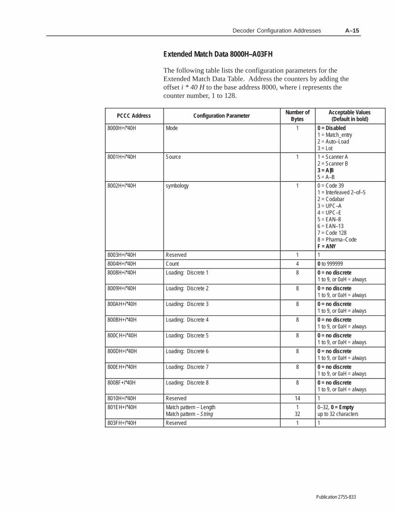
Decoder Configuration Addresses A–15
Publication 2755-833
Extended Match Data 8000H–A03FH
The following table lists the configuration parameters for theExtended Match Data Table. Address the counters by adding theoffset i * 40 H to the base address 8000, where i represents thecounter number, 1 to 128.
ÁÁÁÁÁÁÁÁÁÁÁÁÁÁÁÁÁÁÁÁÁ
PCCC AddressÁÁÁÁÁÁÁÁÁÁÁÁÁÁÁÁÁÁÁÁÁÁÁÁÁÁÁÁÁÁÁÁÁÁÁÁÁÁÁ
Configuration ParameterÁÁÁÁÁÁÁÁÁÁÁÁ
Number ofBytes
ÁÁÁÁÁÁÁÁÁÁÁÁÁÁÁÁÁÁÁÁÁÁÁÁ
Acceptable Values(Default in bold)
ÁÁÁÁÁÁÁÁÁÁÁÁÁÁÁÁÁÁÁÁÁÁÁÁÁÁÁÁ
8000H+i*40H ÁÁÁÁÁÁÁÁÁÁÁÁÁÁÁÁÁÁÁÁÁÁÁÁÁÁÁÁÁÁÁÁÁÁÁÁÁÁÁÁÁÁÁÁÁÁÁÁÁÁÁÁ
Mode ÁÁÁÁÁÁÁÁÁÁÁÁÁÁÁÁ
1 ÁÁÁÁÁÁÁÁÁÁÁÁÁÁÁÁÁÁÁÁÁÁÁÁÁÁÁÁÁÁÁÁ
0 = Disabled1 = Match_entry2 = Auto–Load3 = Lot
ÁÁÁÁÁÁÁÁÁÁÁÁÁÁÁÁÁÁÁÁÁÁÁÁÁÁÁÁ
8001H+i*40H ÁÁÁÁÁÁÁÁÁÁÁÁÁÁÁÁÁÁÁÁÁÁÁÁÁÁÁÁÁÁÁÁÁÁÁÁÁÁÁÁÁÁÁÁÁÁÁÁÁÁÁÁ
Source ÁÁÁÁÁÁÁÁÁÁÁÁÁÁÁÁ
1 ÁÁÁÁÁÁÁÁÁÁÁÁÁÁÁÁÁÁÁÁÁÁÁÁÁÁÁÁÁÁÁÁ
1 = Scanner A2 = Scanner B3 = A|B5 = A–B
ÁÁÁÁÁÁÁÁÁÁÁÁÁÁÁÁÁÁÁÁÁÁÁÁÁÁÁÁÁÁÁÁÁÁÁÁÁÁÁÁÁÁÁÁÁÁÁÁÁÁÁÁÁÁÁÁ
8002H+i*40H ÁÁÁÁÁÁÁÁÁÁÁÁÁÁÁÁÁÁÁÁÁÁÁÁÁÁÁÁÁÁÁÁÁÁÁÁÁÁÁÁÁÁÁÁÁÁÁÁÁÁÁÁÁÁÁÁÁÁÁÁÁÁÁÁÁÁÁÁÁÁÁÁÁÁÁÁÁÁÁÁÁÁÁÁÁÁÁÁÁÁÁÁÁÁÁÁÁÁÁÁÁÁÁÁ
symbology ÁÁÁÁÁÁÁÁÁÁÁÁÁÁÁÁÁÁÁÁÁÁÁÁÁÁÁÁÁÁÁÁ
1 ÁÁÁÁÁÁÁÁÁÁÁÁÁÁÁÁÁÁÁÁÁÁÁÁÁÁÁÁÁÁÁÁÁÁÁÁÁÁÁÁÁÁÁÁÁÁÁÁÁÁÁÁÁÁÁÁÁÁÁÁÁÁÁÁ
0 = Code 391 = Interleaved 2–of–52 = Codabar3 = UPC–A4 = UPC–E5 = EAN–86 = EAN–137 = Code 1288 = Pharma–CodeF = ANY
ÁÁÁÁÁÁÁÁÁÁÁÁÁÁ
8003H+i*40H ÁÁÁÁÁÁÁÁÁÁÁÁÁÁÁÁÁÁÁÁÁÁÁÁÁÁ
Reserved ÁÁÁÁÁÁÁÁ
1 ÁÁÁÁÁÁÁÁÁÁÁÁÁÁÁÁ
1
ÁÁÁÁÁÁÁ8004H+i*40H ÁÁÁÁÁÁÁÁÁÁÁÁÁCount ÁÁÁÁ4 ÁÁÁÁÁÁÁÁ0 to 999999ÁÁÁÁÁÁÁÁÁÁÁÁÁÁÁÁÁÁÁÁÁ
8008H+i*40HÁÁÁÁÁÁÁÁÁÁÁÁÁÁÁÁÁÁÁÁÁÁÁÁÁÁÁÁÁÁÁÁÁÁÁÁÁÁÁ
Loading: Discrete 1ÁÁÁÁÁÁÁÁÁÁÁÁ
8ÁÁÁÁÁÁÁÁÁÁÁÁÁÁÁÁÁÁÁÁÁÁÁÁ
0 = no discrete1 to 9, or 0aH = always
ÁÁÁÁÁÁÁÁÁÁÁÁÁÁÁÁÁÁÁÁÁ
8009H+i*40H ÁÁÁÁÁÁÁÁÁÁÁÁÁÁÁÁÁÁÁÁÁÁÁÁÁÁÁÁÁÁÁÁÁÁÁÁÁÁÁ
Loading: Discrete 2 ÁÁÁÁÁÁÁÁÁÁÁÁ
8 ÁÁÁÁÁÁÁÁÁÁÁÁÁÁÁÁÁÁÁÁÁÁÁÁ
0 = no discrete1 to 9, or 0aH = always
ÁÁÁÁÁÁÁÁÁÁÁÁÁÁ
800AH+i*40H ÁÁÁÁÁÁÁÁÁÁÁÁÁÁÁÁÁÁÁÁÁÁÁÁÁÁ
Loading: Discrete 3 ÁÁÁÁÁÁÁÁ
8 ÁÁÁÁÁÁÁÁÁÁÁÁÁÁÁÁ
0 = no discrete1 to 9, or 0aH = always
ÁÁÁÁÁÁÁÁÁÁÁÁÁÁÁÁÁÁÁÁÁ
800BH+i*40HÁÁÁÁÁÁÁÁÁÁÁÁÁÁÁÁÁÁÁÁÁÁÁÁÁÁÁÁÁÁÁÁÁÁÁÁÁÁÁ
Loading: Discrete 4ÁÁÁÁÁÁÁÁÁÁÁÁ
8ÁÁÁÁÁÁÁÁÁÁÁÁÁÁÁÁÁÁÁÁÁÁÁÁ
0 = no discrete1 to 9, or 0aH = always
ÁÁÁÁÁÁÁÁÁÁÁÁÁÁ
800CH+i*40H ÁÁÁÁÁÁÁÁÁÁÁÁÁÁÁÁÁÁÁÁÁÁÁÁÁÁ
Loading: Discrete 5 ÁÁÁÁÁÁÁÁ
8 ÁÁÁÁÁÁÁÁÁÁÁÁÁÁÁÁ
0 = no discrete1 to 9, or 0aH = alwaysÁÁÁÁÁÁÁ
ÁÁÁÁÁÁÁÁÁÁÁÁÁÁ
800DH+i*40HÁÁÁÁÁÁÁÁÁÁÁÁÁÁÁÁÁÁÁÁÁÁÁÁÁÁÁÁÁÁÁÁÁÁÁÁÁÁÁ
Loading: Discrete 6ÁÁÁÁÁÁÁÁÁÁÁÁ
8ÁÁÁÁÁÁÁÁÁÁÁÁÁÁÁÁÁÁÁÁÁÁÁÁ
0 = no discrete1 to 9, or 0aH = always
ÁÁÁÁÁÁÁÁÁÁÁÁÁÁÁÁÁÁÁÁÁ
800EH+i*40H ÁÁÁÁÁÁÁÁÁÁÁÁÁÁÁÁÁÁÁÁÁÁÁÁÁÁÁÁÁÁÁÁÁÁÁÁÁÁÁ
Loading: Discrete 7 ÁÁÁÁÁÁÁÁÁÁÁÁ
8 ÁÁÁÁÁÁÁÁÁÁÁÁÁÁÁÁÁÁÁÁÁÁÁÁ
0 = no discrete1 to 9, or 0aH = always
ÁÁÁÁÁÁÁÁÁÁÁÁÁÁ
8008F+i*40H ÁÁÁÁÁÁÁÁÁÁÁÁÁÁÁÁÁÁÁÁÁÁÁÁÁÁ
Loading: Discrete 8 ÁÁÁÁÁÁÁÁ
8 ÁÁÁÁÁÁÁÁÁÁÁÁÁÁÁÁ
0 = no discrete1 to 9, or 0aH = always
ÁÁÁÁÁÁÁÁÁÁÁÁÁÁ
8010H+i*40H ÁÁÁÁÁÁÁÁÁÁÁÁÁÁÁÁÁÁÁÁÁÁÁÁÁÁ
Reserved ÁÁÁÁÁÁÁÁ
14 ÁÁÁÁÁÁÁÁÁÁÁÁÁÁÁÁ
1ÁÁÁÁÁÁÁÁÁÁÁÁÁÁÁÁÁÁÁÁÁ
801EH+i*40H ÁÁÁÁÁÁÁÁÁÁÁÁÁÁÁÁÁÁÁÁÁÁÁÁÁÁÁÁÁÁÁÁÁÁÁÁÁÁÁ
Match pattern – LengthMatch pattern – String
ÁÁÁÁÁÁÁÁÁÁÁÁ
132ÁÁÁÁÁÁÁÁÁÁÁÁÁÁÁÁÁÁÁÁÁÁÁÁ
0–32, 0 = Emptyup to 32 characters
ÁÁÁÁÁÁÁ803FH+i*40H ÁÁÁÁÁÁÁÁÁÁÁÁÁReserved ÁÁÁÁ1 ÁÁÁÁÁÁÁÁ1

������� �
Publication 2755-833
���� �� ������� ������
Category of Parameters Parameter Default Setting
Enable Code 39 Yes (No on Pharma-Code Units)
Enable Interleaved 2-of-5 No Guard Bars: No
Enable Codabar No
Enable Code 128 No
ar Co e m ologCode 128 FNC1 Character None
Bar Code SymbologyEnable UPC-A No Supplements: None
Enable UPC-E No Supplements: None
Expand UPC-E No
Enable EAN-8 No Supplements: None
Enable EAN-13 No Supplements: None
Code 39 No Include: No
Check Characters I 2 of 5 No Include: NoChec Characters
Codabar No Include: No
Code 39 00, 00, 00, 00, 00, 00, 00, 00
ar Co e m olog engthsInterleaved 2-of-5 00, 00, 00, 00, 00, 00, 00, 00
Bar Code Symbology LengthsCode 128 00, 00, 00, 00, 00, 00, 00, 00
Codabar 00, 00, 00, 00, 00, 00, 00, 00
Enable Pharma–Code Yes (On Pharma-Code units only)
Quiet Zone Ratio Default
Space Tolerance 15
Pharma–CodeBar Tolerance 15
Pharma–CodeWide to Narrow Bar Ratio 2
Minimum Number of Bars 5
Scanner A Decode Direction Forward
Scanner B Decode Direction Forward
Code Verification List Blank
Laser Light Triggered
Decode Mode Package Detect
No-Read Timer None (0000 msec)
canner ControlInter-Scan Timer None (0000 msec)
Scanner A ControlCapture Count 2
Symbols/Scan 1
Symbols/Package 1
Match Complete 1
Laser Light Triggered
Scanner B Control Decode Mode Coordinated 1Scanner B ControlTrigger Timeout None (0000 msec)

B–2 Factory Default Settings
Publication 2755-833
Category of Parameters Default SettingParameter
Bar Code Symbology Any
Match Code Text String Blank
Match Code Table (1 - 8) Normal State O (Normally Open)Match Code Table (1 - 8)Source A for DS, A|B (A or B) for DD
Duration 0 msec
Scanner A Filter No
ac age etect InputScanner A Sense LO= Package
Package Detect InputScanner B Filter No
Scanner B Sense LO= Package
Counter Status Auto Refresh
Status of Counter Set Enabled
Mode Disabled
ten e Match Co e Ta leSource A for DS, A|B (A or B) for DD
Extended Match Code TableSymbology Any
Match Pattern String Blank
Count 0
Loading Blank (no outputs selected)
Display Data None
Message Format Unformatted
Scroll LCD Display No
Bar Code Strings Position 0
Decoder Performance Position 0
U an C ispla ormat Package Counter Position 0AUX and LCD Display FormatSymbols Not Read CounterPosition
0
Primary Counter 1 Position 0
Primary Counter 2 Position 0
Primary Counter 3 Position 0
Primary Counter 4 Position 0
Primary Counter 5 Position 0
Primary Counter 6 Position 0
Primary Counter 7 Position 0
Primary Counter 8 Position 0
Rule Number 1
Source A|B (A or B)
Symbology Any
Symbol Number All
ost Message eplacementFind String Containging Blank
Host Message Replacementules
Replace Entire String With BlankRules
Minimum Field Length 0
Alignment Right
Fill Character None
Host Message Field Number All
Bar Code String Examples Blank

B–3Factory Default Settings
Publication 2755-833
Category of Parameters Default SettingParameter
Start Character 255 (None)
Source Identifier (for AUX) Blank
Source Identifier (for A) Blank
Source Identifier (for B) Blank
Header String Blank
Field Delimiter None
ost Message ormat
Number of Fields in Message All
Host Message Format Send Symbology No
Send Package Count No
Send Bar Code Strings Yes
Send Decoder Performance No
End Message CrLf
Default No-Read String Blank
No-Read Replacements Strings(1–16)
Blank
Baud Rate* 9600
Bits/Character* 8 Data, 1 Stop
Parity* None
Host Protocol* RS232
Device Address* 1
Host Communications ACK Character* 255 (None)Host Communications
Pa a t a d it an a t iNAK Character* 255 (None)
Parameters marked with an asteriskui a a and ta t to ta
Start Character Scanner A 255 (Disabled)require a save and restart to take
effect Stop Character Scanner A 255 (Disabled)effectStart Character Scanner B 255 (Disabled)
Stop Character Scanner B 255 (Disabled)
Large Buffer No
Send Host Message At End of Trigger
Transmission Check None
Enable Keyboard Entry No
Confirm Entry No
AUX Data Format Unformatted
Aux Terminal Data Entry Rubout Character 008 BS (Backspace)
Echo Data to Terminal No
Size of Display 80
Default Prompt Message Blank
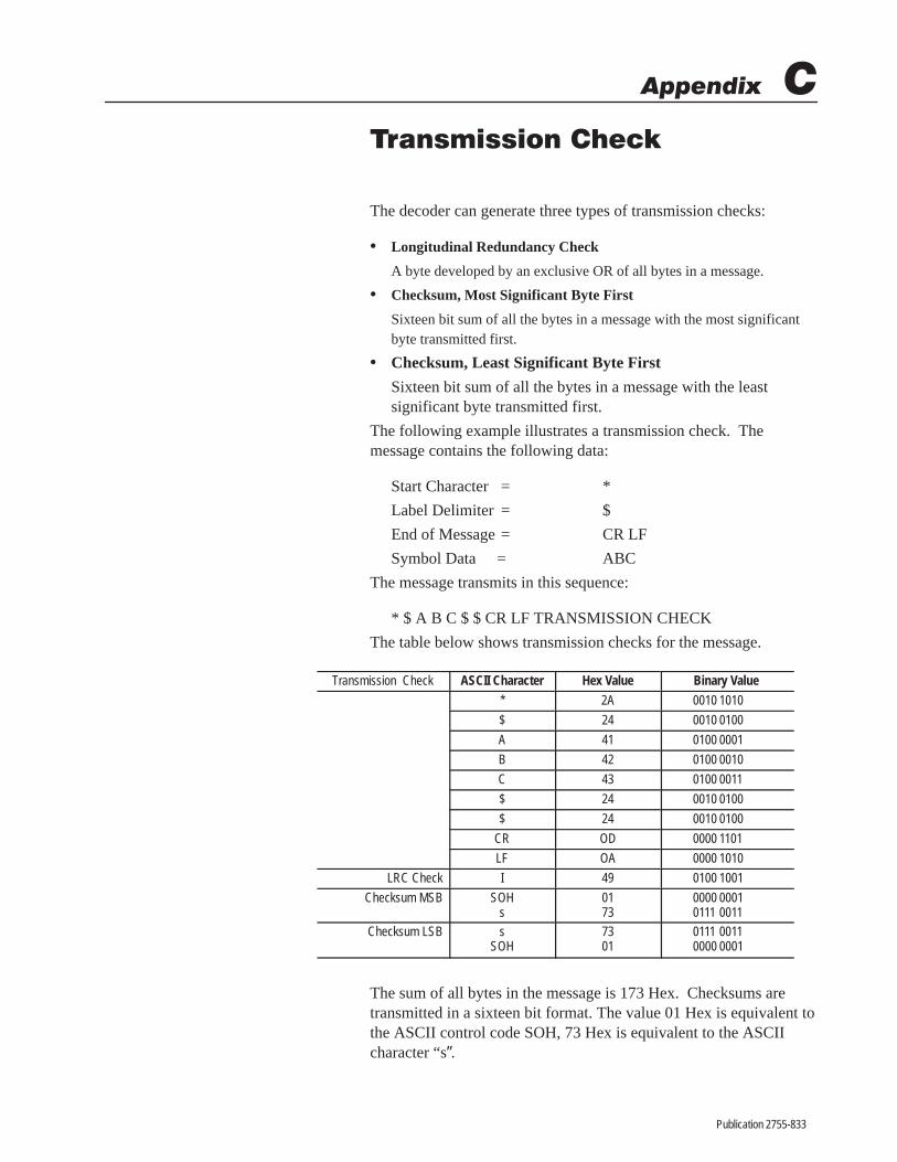
������� �
Publication 2755-833
� ��������� ����
The decoder can generate three types of transmission checks:
• Longitudinal Redundancy Check
A byte developed by an exclusive OR of all bytes in a message.
• Checksum, Most Significant Byte First
Sixteen bit sum of all the bytes in a message with the most significantbyte transmitted first.
• Checksum, Least Significant Byte First
Sixteen bit sum of all the bytes in a message with the leastsignificant byte transmitted first.
The following example illustrates a transmission check. Themessage contains the following data:
Start Character = *
Label Delimiter = $
End of Message = CR LF
Symbol Data = ABC
The message transmits in this sequence:
* $ A B C $ $ CR LF TRANSMISSION CHECK
The table below shows transmission checks for the message.
Transmission Check ASCII Character Hex Value Binary Value
* 2A 0010 1010
$ 24 0010 0100
A 41 0100 0001
B 42 0100 0010
C 43 0100 0011
$ 24 0010 0100
$ 24 0010 0100
CR OD 0000 1101
LF OA 0000 1010
LRC Check I 49 0100 1001
Checksum MSB SOHs
0173
0000 00010111 0011
Checksum LSB sSOH
7301
0111 00110000 0001
The sum of all bytes in the message is 173 Hex. Checksums aretransmitted in a sixteen bit format. The value 01 Hex is equivalent tothe ASCII control code SOH, 73 Hex is equivalent to the ASCIIcharacter “s”.

������� �
Publication 2755-833
������� �� �� ����
This appendix provides instructions on how to setup and connect thefollowing terminals to the AUX port of the NEMA Type 1 or Type 4decoder.
• Lear Siegler ADM 3E
• DEC VT100
• 1784-T45
• 1771-T1, -T2, -T3
Pin Abb. Function1 GND Chassis Ground
2 TD Transmit Data carries data from terminal to decoder. (input to decoder)
3 RD Receive Data carries data from decoder to terminal. (Output from de-coder)
7 SIG GND Signal Ground
15 AUX TerminalSelector +
AUX Terminal Selector. Determines whether the AUX terminal is usedfor configuration or manual data entry. To use the AUX terminal formanual data entry, tie pin 15 to 16. To use the AUX terminal for configu-ration, leave pins 15 and 16 open.
16 AUX TerminalSelector –
Connect to pin 15 to use the AUX terminal for manual data entry func-tions. When connected to 15, you cannot access the configurationmenus.
1725
IN8+IN8–
Auto Load Input. You can connect a normally opened (N.O.) contactbetween pins 17 and 25. Close the contacts to activate the AutoLoadFunction. See Chapter 6 and Appendix H.
Pin Abb. FunctionA GND Chassis Ground
B TD Transmit Data carries data from terminal to decoder (Input to decoder).
C RD Receive Data carries data from decoder to terminal (Output from decod-er).
D SIG GND Signal Ground
G AUX TerminalSelector +
AUX Terminal Selector. Determines whether the AUX terminal is usedfor configuration or manual data entry. To use the AUX terminal formanual data entry, tie pin G to H. To use the AUX terminal for configura-tion, leave pins G and H open.
H AUX TerminalSelector –
Connect to pin G to use the AUX terminal for manual data entry func-tions. When connected to G, you cannot access the configuration me-nus.
KL
IN8+IN8–
Auto Load Input. You can connect a normally opened (N.O.) contactbetween pins K and L. Close the contacts to activate the AutoLoadFunction. See Chapter 6 and Appendix H.
Appendix Objectives
Connecting Terminal toAUX Port on NEMA Type 1Decoder
AUX PORT (female) Connector
114
1325
Connecting Terminal toAUX Port of NEMA Type 4Decoder
C
D
B
E
P
A
S
N
M
FG
U
L
H
K
TJ V
R
AUX PORT (male) Connector

Setting Up TerminalsD–2
Publication 2755-833
Follow these steps if using a Lear Siegler ADM 3E terminal:
1. Construct a cable to connect the terminal to the decoder. Use aBelden 8303, Alpha 45123, or equivalent type of cable. Use thefollowing connector pinouts:
237
237
Note: Connect shield to shellof cable connectors at both ends.
Transmit DataReceive DataSignal Ground
C
B
D
NEMA NEMA Type 1Type 4
Decoder Terminal
25-pin maleMale 19-pin NEMA Type 4 or Female25-pin D Shell Connector
2. Plug terminal into power supply.
3. Power on terminal.
4. Press [Shift] [SETUP] to enter setup mode.
5. Use the arrow keys to set the following parameters on theterminal:
• Full Duplex (FDX)• 9600 Baud Rate• 8 Data Bits per Character• No Parity• XON/XOFF Flow Control or Handshake• Blinking Block Cursor
6. To save the selected parameters, press [Ctrl] [S].
7. Exit setup mode by pressing [Shift] [SETUP].
8. You are now ready to configure the decoder. See Chapter 5.
Lear SieglerADM 3E Terminal

Setting Up Terminals D–3
Publication 2755-833
Follow these steps if using a DEC VT100 terminal:
1. Construct a cable to connect the VT100 to the decoder. Use aBelden 8303, Alpha 45123, or equivalent type of cable. Use thefollowing connector pinouts:
237
327
Note: Connect shield to shellof cable connectors at both ends.
Transmit DataReceive DataSignal Ground
C
B
D
NEMA NEMA Type 1Type 4
TerminalDecoder
25-pin FemaleMale 19-pin NEMA Type 4 or Female25-pin D Shell Connector
2. Plug terminal into power supply.
3. Power on terminal.
4. Enter Set-Up B on terminal. The following figure shows onesetup.
SETUP BTO EXIT PRESS ”SET-UP”
1 0101 2 0011 3 0000 4 0010 T SPEED 9600 R SPEED 9600
1 . . 01Cursor BlockScreen DarkDon’t CareDon’t Care
2 . . 11XON/XOFF ONANSIDon’t CareDon’t Care
3 . 00 .Don’t CareNew Line OffWrap OffDon’t Care
4 . 01060 Hz8 BitsParity OffDon’t Care
5. You are now ready to configure the decoder. See Chapter 5.
DEC VT100 Terminal

Setting Up TerminalsD–4
Publication 2755-833
Follow these steps if using an Allen-Bradley 1784-T45 or -T47computer:
1. Construct a cable to connect the terminal to the decoder. Use aBelden 8303, Alpha 45123, or equivalent type of cable. Use thefollowing connector pinouts:
237
234
Note: Connect shield to shellof cable connectors at both ends.
Transmit DataReceive DataSignal Ground
567820
.DTR
CD
DSR
RTSCTS
C
B
D
NEMA NEMA Type 1Type 4
25-pin Female
Decoder Terminal
Male 19-pin NEMA Type 4 or Female25-pin D Shell Connector
2. Power on the terminal. The switch is located on the left side ofthe unit.
The terminal will beep once, and then test itself. When the test iscomplete, a message appears. The last line should indicate that alltests have passed.
3. Press [CTRL][ALT][CMD] key sequence to display the systemMain Menu (Press the [CMD] key while holding down both the[ALT] and [CTRL] keys.
4. Set the T45 terminal emulation to the following settings (Refer tothe terminal documentation for additional information):
• F1 DGC D200 Terminal• F2 Modem = External• F3 Flow Control = On• F4 Duplex = Full• F6 Print = Off
5. Set the COM1 parameters to:
• F1 Baud Rate = 9600• F2 Parity = None• F3 Data Bits = 8• F4 Stop Bits = 1• F5 Type = Standard PC Compatible Com
Note: If using an internal modem, disable it using the MODEcommand.
Allen-Bradley 1784-T45 orT47 ProgrammingTerminal

Setting Up Terminals D–5
Publication 2755-833
6. When the Select CRT Type menu appears, select Data GeneralDT100 emulation.
7. You are now ready to configure the decoder. See Chapter 5.
Follow these steps if using an Allen-Bradley 1770-T1, -T2, or -T3terminal:
1. Construct a cable to connect the decoder to Channel B of theterminal. Use a Belden 8303, Alpha 45123, or equivalent type ofcable. Use the following connector pinouts:
237
237
Note: Connect shield to shellof cable connectors at both ends.
1825
.
.
Transmit DataReceive DataSignal Ground
C
B
D
NEMA NEMA Type 1Type 4
25-pin Male
Decoder Terminal
Male 19-pin NEMA Type 4 or Female25-pin D Shell Connector
2. Plug terminal into power supply.
3. Install the alphanumeric keytop overlay on the terminal keyboard.
4. Power on terminal. Enter 12 to select alphanumeric.
5. Select Alphanumeric Mode and set the following parameters(Refer to your terminal documentation for additionalinformation):
Baud Rate 9600
Parity = No
Stop Bits = 1
Channel Config. = B IN/OUT
Duplex = Full
Channel C = On or Off
Cursor = On
Auto Line Feed after Return = Off
Control Code Display = Off
6. You are now ready to configure the decoder. See Chapter 5.
Note: Because there is no flow control with the 1770-T1, -T2, or-T3 terminals, the Series B Revision A decoder could transmit datatoo quickly. This caused the terminal to display garbled characters orlock up. To resolve that problem, the Revision B decoder sends datain smaller bursts to these terminals.
Allen-Bradley1770-T1, -T2, -T3 Terminals

Setting Up TerminalsD–6
Publication 2755-833
Follow these steps if using one of the Allen-Bradley 2708-DH5 Attended Workstations:
1. Construct a cable to connect the decoder to the COM1 port of the2708-DH5 terminal. Use a Belden 8303, Alpha 45123, orequivalent type of cable. Use the following connector pinouts:
237
325
C
B
D
NEMA NEMA Type 1Type 4
9-pin Female
Decoder Terminal
Male 19-pin NEMA Type 4 or Female25-pin D Shell Connector
2. Plug terminal into power supply.
3. Power on terminal.
4. Select Network Menu (option 1) and set the followingparameters:
Terminal Number = 0
Terminal Type = Normal
The rest of the network parameters are not applicable.
5. Select Comm Port Menu (option 2) and set the followingparameters:
Comm Mode XON/XOFF
Comm Baud Rate = 9600
Comm Data Bits = 8
Comm Parity = None
Comm Stop Bits = 1
Comm CRLF = Disabled
Comm Echo = Disabled
Comm Handshake = Disabled
The rest of the parameters are not applicable.
6. You are now ready to configure the decoder. See Chapter 5.
2708-DH5 AttendedWorkstations

������� �
Publication 2755-833
������ � � ���
The HOST port of the decoder allows communication with a hostdevice using three standard interfaces: RS-232, RS-422, RS-485.This appendix contains connection diagrams for each interface. Usethese diagrams when connecting a host device to the HOST port ofthe decoder.
The HOST port on the NEMA Type 4 decoder has a 19-pin (male)connector. The HOST port on the NEMA Type 1 decoder has a25-pin (female) D shell connector.
C
D
B
E
P
A
S
N
M
FG
U
L
H
K
TJ V
RC
D
B
E
P
A
S
N
M
FG
U
L
H
K
TJ V
R
NEMA Type 1HOST Port (Female) Connector
114
1325
NEMA Type 4HOST Port (Male) Connector
NEMA 1Pins
NEMA 4Pins
Abb. Function
1 A GND Chassis Ground
2 C TD RS-232 Transmit Data (from decoder to host).
3 B RD RS-232 Receive Data (from host).
4 F RTS RS-232 Request to Send
5 J CTS RS-232 Clear to Send
20 E DTR RS-232 Data Terminal Ready
6 H DSR RS-232 Data Set Ready
7 D SIG GND RS-232 Signal Common
9 L SHLD RS-485 Shield Ground
12 M 485 TERM RS-485 Line Termination. Jumpers to 13 or N. Terminates decoder at each end of network.
13 N 485 A/TERM RS-485 Line Termination. Jumpers to 12 or M. Terminates decoder at each end of network.
14 P TxB+ RS-422(B) or RS-485(B) Transmit Data (from decoder to host).
15 R TxA- RS-422(A) or RS-485(A) Transmit Data (from decoder to host).
16 S RxA ’– RS-422(A) Receive Data (from host).
17 T RxB ’+ RS-422(B) Receive Data (from host).
18 U 422/A TERM RS-422 Line Termination. Jumpers to 19 or V. Terminates decoder at each end of network.
19 V 422 TERM RS-422 Line Termination. Jumpers to 18 or U. Terminates decoder at each end of network.
The cable that connects the decoder to the host varies depending onthe communication standard and the type of connector on the serialcommunication port of the host.

Connecting to a HostE–2
Publication 2755-833
Appendix F lists the host protocol options for each communicationinterface.
Figure E.1 shows how to connect the NEMA Type 1 decoder to ahost using RS-232. Use a Belden 8303 cable, Alpha 45123 cable, orequivalent.
Figure E.1 Connecting NEMA Type 1 Decoder to Host usingRS-232
SIG GND➂
RTS
1
2
3
4
5
7
20
GND
TD➂
RD➂
CTS
DTR
RD
TD
CTS
RTS
DSR
Host Port 25-pin DB Connectoron Decoder➀
Host RS-232 Port
*
*
*
*
*
*
* Pin designations depend on host device.
Shield➁
➀ DTE = Data Terminal Equipment ➁ When nonmetallic connecter shell used. (If metal connector, connect shield to shell).➂ Pins 2, 3, and 7 are the minimum connections.
All unused pins should be left open.
6DSR DTR*SIG GND
Pins 4, 5, and 20 are optional flow control lines. Flow controloptions are:
• RS-232
No flow control.
• RS-232 XON/XOFF
The XOFF character from the host suspends transmission and theXON character resumes transmission. The receiving deviceremoves the XON/XOFF characters from the message.
• RS-232 RTS/CTS-1
Enables the RS-232 (RTS and CTS) control lines for flow control.
• RS-232 RTS/CTS-2
Enables the RS-232 (RTS and CTS) control lines for flow control.Use this mode of flow control to communicate with Catalog No.2760-RA or -RB module.
The RS-232 interface and flow control are selected on the HostCommunications configuration screen.
RS-232 Interface

Connecting to a Host E–3
Publication 2755-833
Pin # ModemControl Line
Function Descriptions
20 DTR RTS/CTS-1RTS/CTS-2
The decoder sends a DTR (Data Terminal Ready) signal to tell the host the decoder is online and capa-ble of receiving data from the host. The DTR line remains on while the decoder is on.
4 RTS RTS/CTS-1 The decoder sends the RTS (Request to Send) signal to tell the host it is ready to send data. When thehost receives an RTS signal from the decoder, the host must assert CTS to tell the decoder to beginsending data. When the decoder stops sending an RTS, the host must stop sending a CTS before thedecoder can assert RTS again.
4 RTS RTS/CTS-2 The decoder sends the RTS (Request to Send) signal to tell the host it can accept data. The host onlysends data when RTS is on.
5 CTS RTS/CTS-1RTS/CTS-2
The host sends the CTS (Clear to Send) signal to the decoder if it can accept data. The decoder onlysends data if CTS is on.
Figure E.2 shows how to connect the NEMA Type 4 decoder to ahost using RS-232. Use a Belden 8303 cable, Alpha 45123 cable, orequivalent.
Figure E.2 Connecting NEMA Type 4 Decoder to a HostComputer using RS-232
SIG GND➁
RTS
C
B
F
J
D
E
TD➁
RD➁
CTS
DTR
RD
TD
CTS
RTS
SIG GND
DSR
Host Port 2755-NC17 Connectoron Decoder
Host RS-232 Port
*
*
*
*
*
*
* Pin designations depend on host device.
Shield➀
➀ Ground to back shell following 2755-NC17 instructions.➁ Pins C, B, and D are the minimum connections.
All unused pins should be left open.
HDSR DTR*
Pins F, J, and E are optional flow control lines. Flow control optionsare:
• RS-232
No flow control.
• RS-232 XON/XOFF
The XOFF character from the host suspends transmission and theXON character resumes transmission. The receiving deviceremoves the XON/XOFF characters from the message.
• RS-232 RTS/CTS-1
Enables the RS-232 (RTS and CTS) control lines for flow control.

Connecting to a HostE–4
Publication 2755-833
• RS-232 RTS/CTS-2
Enables the RS-232 (RTS and CTS) control lines for flow control.Use this mode of flow control to communicate with Catalog No.2760-RA or -RB module.
The RS-232 interface and flow control are selected on the HostCommunications configuration screen.
Pin # ModemControl Line
Function Descriptions
E DTR RTS/CTS-1RTS/CTS-2
The decoder sends a DTR (Data Terminal Ready) signal to tell the host the decoder is online and capa-ble of receiving data from the host. The DTR line remains on while the decoder is on.
F RTS RTS/CTS-1 The decoder sends the RTS (Request to Send) signal to tell the host it is ready to send data. When thehost receives an RTS signal from the decoder, the host must assert CTS to tell the decoder to beginsending data. When the decoder stops sending an RTS, the host must stop sending a CTS before thedecoder can assert RTS again.
F RTS RTS/CTS-2 The decoder sends the RTS (Request to Send) signal to tell the host it can accept data. The host onlysends data when RTS is on.
J CTS RTS/CTS-1RTS/CTS-2
The host sends the CTS (Clear to Send) signal to the decoder if it can accept data. The decoder onlysends data if CTS is on.
Figure E.3 shows how to connect the NEMA Type 4 decoder to ahost using RS-422. Use Belden cable 9829 (shielded, twisted pair) orequivalent.
Figure E.3 Connecting NEMA Type 4 Decoder to Host usingRS-422
1
14
15
16
17
18
19
GND
TxB +
TxA –
RxA’–
RxB’ +
RxB’ +
RxA’ –
TxA –
TxB +
Host Port 25-pin DB Connectoron Decoder➀
Host RS-422 Port
*
*
*
*
* Pin designations depend on host device.
Shield➁
➀ DTE = Data Terminal Equipment➁ When nonmetallic connector shells used.
(If metal connector shell, connect shieldto shell.)
RS-422 Termination
7
* SIG GND
SIG GND
RS-422 Interface

Connecting to a Host E–5
Publication 2755-833
The RS-422 interface uses pins 7, 14, 15, 16, 17, 18, and 19 of theHOST port connector. The transmit data and receive data lines are:
Pin 14 TxB+ Transmits data from the decoder to the host.
Pin 15 TxA– Transmits data from the decoder to the host.
Pin 16 RxA’– Receives data from the host.
Pin 17 RxB’+ Receives data from the host.
RS-422 communication lines are unterminated. To enable networktermination (120 Ohm resistor in series with a 0.01 microfaradcapacitor), connect pins 18 and 19 together.
Important: We recommend you terminate the RS-422 lines ifexcessive noise occurs on long RS-422 communication links.
RS-422 does not use modem control lines. However, theconfiguration software does allow optional flow control usingXON/XOFF characters. The options are:
• RS422. No flow control.
• RS422 XON/XOFF. Enable XON/XOFF flow control.
The RS-422 communication interface and protocol is selected duringconfiguration. See the Host Communications configuration screen.
Figure E.4 shows how to connect the NEMA Type 4 decoder to ahost using RS-422. Use Belden cable 9829 (shielded, twisted pair) orequivalent.
Figure E.4 Connecting NEMA Type 4 Decoder to Host usingRS-422
P
R
S
T
U
V
TxB +
TxA –
RxA’–
RxB’ +
RxB’ +
RxA’ –
TxA –
TxB +
Host RS-422 Port
*
*
*
*
* Pin designations depend on host device.
Shield➀
➀ Ground to back shell following 2755-NC17 instructions.
RS-422 Termination
D
* SIG GND
SIG GND
Host Port 2755-NC17 Connectoron Decoder

Connecting to a HostE–6
Publication 2755-833
The RS-422 interface uses pins D, P, R, S, T, U, and V of the HOSTport connector. The transmit data and receive data lines are:
Pin P TxB+ Transmits data from the decoder to the host.
Pin R TxA– Transmits data from the decoder to the host.
Pin S RxA’– Receives data from the host.
Pin T RxB’+ Receives data from the host.
RS-422 communication lines are unterminated. To enable networktermination (120 Ohm resistor in series with a 0.01 microfaradcapacitor), connect pins U and V together.
Important: We recommend you terminate the RS-422 lines ifexcessive noise occurs on long RS-422 communication links.
RS-422 does not use modem control lines. However, theconfiguration software does allow optional flow control usingXON/XOFF characters. The options are:
• RS422. No flow control.
• RS422 XON/XOFF. Enable XON/XOFF flow control.
The RS-422 communication interface and protocol is selected duringconfiguration. See the Host Communications configuration screen.
The DH485 interface allows you to multi-drop up to 31 decoders toeach port of the Flexible Interface Module (Catalog No. 2760-RB).Each of the three ports of the module operates as a separatecommunications network.
Figure E.5 shows how to connect the NEMA Type 1 decoder to aDH485 network. Use Belden cable 9842 (or equivalent).
RS-485 UsingDH485 Protocol

Connecting to a Host E–7
Publication 2755-833
Figure E.5 Connecting NEMA Type 1 Decoder to DH485Network
.
9
7
14
15
12
13
Shield
TxB +
TxA –
RS-485 Termination➁
Shield
Host Port25-pin DB Connector on Decoder
Host RS-485 Port
*
*
*
*
* Pin designations depend on host device.
Shield➀
➀ Only one of the devices in the network must have the cable shield connected to chassis ground. Do this by connecting shield to pin 1 instead of pin 9.➁ Enable line termination for the device at each end of the network. To enable line termination, connect pins 12 and 13 together. For all other devices in the network, leave these pins open.
SIG GND SIG GND
TxB +
TxA –
The following parameters are fixed for DH485 communications:
• 8 Data bits
• Even parity
• 1 Stop Bit
The host protocol options are:
• DH485 PCCC-1. PCCC commands with write replies
• DH485 PCCC-2. PCCC commands without write replies
• DH485 ASCII-1. ASCII commands with responses
• DH485 ASCII-2. ASCII commands without responses.
The communication interface and host protocol is selected duringconfiguration. See the Host Communications configuration screen.
Figure E.6 shows how to connect the NEMA Type 4 decoder to aDH485 network. Use Belden cable 9842 (or equivalent).

Connecting to a HostE–8
Publication 2755-833
Figure E.6 Connecting NEMA Type 4 Decoder to DH485Network
L
D
P
R
M
N
Shield
TxB +
TxA –
RS-485 Termina-tion➁
Shield
Host Port 2755-NC17on Decoder
Host RS-485 Port
*
*
*
*
* Pin designations depend on host device.
Shield➀
➀ Only one of the devices in the network must have the cable shield connected to chassis ground. Do this by connecting shield to pin A instead of pin L.➁ Enable line termination for the device at each end of the network. To enable line termination, connect pins M and N together. For all other devices in the network, leave pins M and N open.
SIG GND SIG GND
TxB +
TxA –
The following parameters are fixed for DH485 communications:
• 8 Data bits
• Even parity
• 1 Stop Bit

Connecting to a Host E–9
Publication 2755-833
The host protocol options are:
• DH485 PCCC-1. PCCC commands with write replies
• DH485 PCCC-2. PCCC commands without write replies
• DH485 ASCII-1. ASCII commands with responses
• DH485 ASCII-2. ASCII commands without responses.
The communication interface and host protocol is selected duringconfiguration. See the Host Communications configuration screen.

������� �
Publication 2755-833
���� ��������
The following table lists the available options for hostcommunications.
PhysicalInterface
Flow Control CommunicationsLink Layer
Application Layer
ConfigurationSelections
RS-232 None - ASCII RS232
RS-232 None ACK/NAK ASCII RS232ACK Character DefinedNAK Character Defined
RS-232 XON/XOFF - ASCII RS232 XON/XOFF
RS-232 XON/XOFF ACK/NAK ASCII RS232 XON/XOFFACK Character DefinedNAK Character Defined
RS-232 RTS/CTS Modem Controls
- ASCII RS232 RTS/CTS-1
RS-232 RTS/CTS Modem Controls
ACK/NAK ASCII RS232 RTS/CTS-1ACK Character DefinedNAK Character Defined
RS-232 RTS/CTSBulletin 2760 Modem Controls
- ASCII RS232 RTS/CTS-2
RS-232 RTS/CTSBulletin 2760 Modem Controls
ACK/NAK ASCII RS232 RTS/CTS-2ACK Character DefinedNAK Character Defined
RS-422 None - ASCII RS422
RS-422 None ACK/NAK ASCII RS422ACK Character DefinedNAK Character Defined
RS-422 XON/XOFF - ASCII RS422 XON/XOFF
RS-422 XON/XOFF ACK/NAK ASCII RS422 XON/XOFFACK Character DefinedNAK Character Defined
RS-485 DH485 Local Area Network DH485 Local Area Network PCCC with Write Replies RS485 PCCC-1LSAP 128 or 1
RS-485 DH485 Local Area Network DH485 Local Area Network PCCC without Write Replies RS485 PCCC-2LSAP 128 or 1
RS-485 DH485 Local Area Network DH485 Local Area Network ASCII with Responses RS485 ASCII-1LSAP 128 or 1
RS-485 DH485 Local Area Network DH485 Local Area Network ASCII without Responses RS485 ASCII-1LSAP 128 or 1

������� �
Publication 2755-833
��� �� ����� � ������
Figures G.1 through G.3 show typical output module applications.Outputs are open when power is first applied to the decoder (duringinitial diagnostics) and again when the decoder is powered off.
DC Output Module Application
Figure G.1 illustrates a typical DC output module application. Whenusing high impedance loads, you may have to add an additionalresistor (R) in parallel with the load. Select a value for R thatmaintains a minimum current of 10mA through the output module inthe closed state. Typical R values range from 300 to 6,000 ohmsdepending on the source voltage.
Figure G.1 DC output module application
– 4 +
Fuse
Connector Block
Enclosure Conduit Hole
DC Output Module➀
MOD 1-8
➀ Output module functions as switch, not a power source.DC Source 3-60 VDC
R
Load
– +
Note: For highly inductive or capacitive loads, make sure that thecurrent does not exceed the maximum ratings of the fuse or module.You can use a diode to protect the module. See Figure G.3.

Output Module ApplicationsG–2
Publication 2755-833
AC Output Module Application
Figure G.2 illustrates a typical AC output module application. Whenusing high impedance loads, you may have to add an additionalresistor (R) in parallel with the load. Select a value for R thatmaintains a minimum current of 50 mA RMS through the outputmodule in the closed state.
Figure G.2 AC output module application
– 2 +
FuseConnector Block
Enclosure Conduit Hole
AC Output Module➀
MOD 1-8
AC Source
➀ Output module functions as switch, not a power source.
R
Load
Note: For highly inductive or capacitive loads, make sure that thecurrent does not exceed the maximum ratings of the fuse or module.You can use a diode to protect the module. See Figure G.3.
Using a Diode to Protect Output Module
Back EMF (Electromotive Force) is sometimes generated when aninductive load is switched off. Back EMF takes the path of leastresistance into the output module, which may cause the module toblow. To protect the module from back EMF, insert a diode inparallel with the inductive device to dissipate back EMF.

Output Module Applications G–3
Publication 2755-833
Figure G.3 Using diode to protect module
– 2 +
FuseConnector Block
Enclosure Conduit Hole
DC Output Module➀
MOD 1-8
DC Source➀ Output module functions as switch, not a power source.
Load
Diode
– +

������� �
Publication 2755-833
��������� � ����� ���������� ���������� �
There are three ways to activate the AutoLoad function described inChapter 5:
1. 12 VDC power supply terminal on I/O Module board connects toinput module (in position 8 of I/O Module Board) and a normallyopened (N.O.) contact, providing power to the input module. SeeFigure H.1.
2. External AC or DC power source connects to input module (inposition 8 of I/O Module Board) and a normally opened (N.O.)contact, providing power to the input module. See Figure H.2
3. A normally opened (N.O.) contact connects directly to pins inAUX Port Connector. This method does not require an I/OModule Board with installed input module or a power source.See Figure H.3.
AutoLoad Input Module Application (powered internally)
Figure H.1 illustrates the AutoLoad Input module application that ispowered internally. A DC input module is installed in position 8 ofthe I/O Module Board. A switch (N.O. contact) provides input to themodule to load bar code data into the match code table. The moduleand switch receive power from the 12 V DC terminal on the I/Oboard.
Figure H.1 AutoLoad input module application (poweredinternally)
– 8 + – +
12 V DCPowerSource
Mechanical orPhotoElectric Switch
Fuse
Connector Block
Enclosure Conduit Hole
DC Input Module
MOD8 Only

Electrical Interfaces for AutoLoad ApplicationsH–2
Publication 2755-833
AutoLoad Input Module Application (powered externally)
Figure H.2 illustrates the AutoLoad Input module application that ispowered externally. An AC/DC input module is installed in position8 of the I/O Module Board. A push button (normally opened contact)provides input to the module to load bar code data into the matchcode table. The module and switch receive power from an externalAC or DC source.
!ATTENTION: To guard against enclosure damage,align the conduit so as to prevent unnecessary stress onthe enclosure walls.
Figure H.2 AutoLoad input module application (poweredexternally
– 8 +
FuseConnector Block
Enclosure Conduit Hole
AC/DC InputModule
MOD8 Only
AC or DC Source
+
–
Auto LoadPush Button
– +
AutoLoad Activated by Aux Port Connector
Another way to activate the AutoLoad function is by connecting apush button (normally opened contact) directly to pins 17 and 25 (orK and L) of the AUX port connector. This method does not requirean I/O Module Board with installed input module or a powersource.

Electrical Interfaces for AutoLoad Applications H–3
Publication 2755-833
Figure H.3 shows the connection between a normally opened contactand pins on the NEMA Type 1 or NEMA Type 4 connector.
Figure H.3 AutoLoad function activated by AUX connector
C
D
B
E
P
A
S
N
M
FG
U
L
H
K
TJ V
R
1
13
NEMA Type 1Aux Port (female) Connector
NEMA Type 4
14
Aux Port (Male) Connector
Use the Catalog No. 2755-NC17 Connector Kit to fabricate cable.
17
25

������� �
Publication 2755-833
����� ������ ���

ASCII Character SetI–2
Publication 2755-833
The following parameters allow you to enter non-printable ASCIIcharacters into the edit field:
• •Source Identification Message
• •Header Message
• •No-Read Message
• •Match Table Entry
• •Default Prompt Message
The table below shows you how to enter non-printable ASCII controlcharacters (ASCII 0 through 31) into a text string. For example, toenter carriage return and line feed control characters, enter %M%J.The decoder interprets %M%J as the ASCII control characters CRand LF. The % character is equivalent to ASCII 37 (decimal).
You always enter non-printable control characters as a 2 charactersequence and the second character must be listed in the followingtable. To enter the % character, use %%.
ASCII ControlCharacter
Enter: ASCII ControlCharacter
Enter: ASCII ControlCharacter
Enter:
NUL %@ VT %K SYN %V
SOH %A FF %L ETB %W
STX %B CR %M CAN %X
ETX %C SO %N EM %Y
EOT %D SI %O SUB %Z
ENQ %E DLE %P ESC %[
ACK %F DC1 %Q FS %\
BEL %G DC2 %R GS %]
BS %H DC3 %S RS %^
HT %I DC4 %T US %_
LF %J NAK %U
Entering Non-PrintableASCII Characters

������� �
Publication 2755-833
���� �������
Use a photocopy of the table below to record your own customparameter settings as you develope new applications. This table is ablank version of the default settings table from Appendix B.
Category of Parameters Parameter Default Setting
Enable Code 39
Enable Interleaved 2-of-5
Enable Codabar
Enable Code 128
ar Co e m ologCode 128 FNC1 Character
Bar Code SymbologyEnable UPC-A
Enable UPC-E
Expand UPC-E
Enable EAN-8
Enable EAN-13
Code 39
Check Characters I 2 of 5Chec Characters
Codabar
Code 39
ar Co e m olog engthsInterleaved 2-of-5
Bar Code Symbology LengthsCode 128
Codabar
Enable Pharma–Code
Quiet Zone Ratio
Space Tolerance
Pharma–CodeBar Tolerance
Pharma–CodeWide to Narrow Bar Ratio
Minimum Number of Bars
Scanner A Decode Direction
Scanner B Decode Direction
Code Verification List
Laser Light
Decode Mode
No-Read Timer
canner ControlInter-Scan Timer
Scanner A ControlCapture Count
Symbols/Scan
Symbols/Package
Match Complete
Laser Light
Scanner B Control Decode ModeScanner B ControlTrigger Timeout

Custom SettingsJ–2
Publication 2755-833
Category of Parameters Default SettingParameter
Bar Code Symbology
Match Code Text String
Match Code Table (1 - 8) Normal StateMatch Code Table (1 - 8)Source
Duration
Scanner A Filter
ac age etect InputScanner A Sense
Package Detect InputScanner B Filter
Scanner B Sense
Counter Status
Status of Counter Set
Mode
ten e Match Co e Ta leSource
Extended Match Code TableSymbology
Match Pattern String
Count
Loading
Display Data
Message Format
Scroll LCD Display
Bar Code Strings Position
Decoder Performance Position
U an C ispla ormat Package Counter PositionAUX and LCD Display FormatSymbols Not Read CounterPositionPrimary Counter 1 Position
Primary Counter 2 Position
Primary Counter 3 Position
Primary Counter 4 Position
Primary Counter 5 Position
Primary Counter 6 Position
Primary Counter 7 Position
Primary Counter 8 Position
Rule Number
Source
Symbology
Symbol Number
ost Message eplacementFind String Containging
Host Message Replacementules
Replace Entire String WithRules
Minimum Field Length
Alignment
Fill Character
Host Message Field Number
Bar Code String Examples
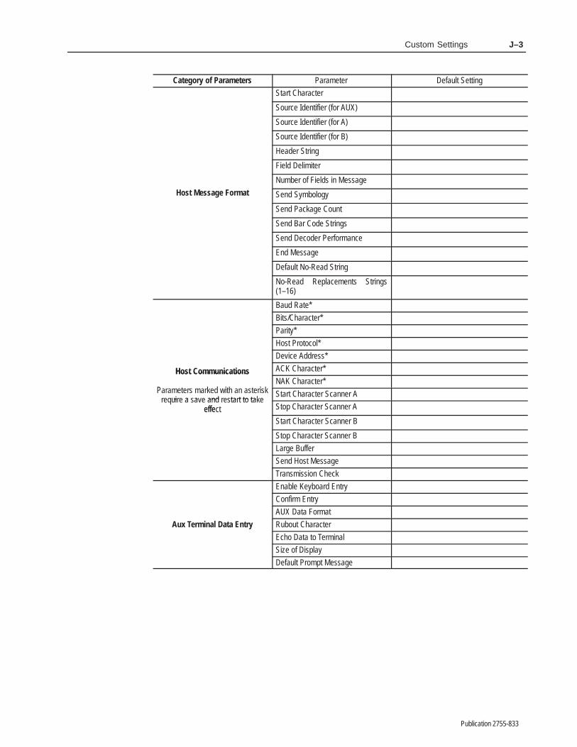
Custom Settings J–3
Publication 2755-833
Category of Parameters Default SettingParameter
Start Character
Source Identifier (for AUX)
Source Identifier (for A)
Source Identifier (for B)
Header String
Field Delimiter
ost Message ormat
Number of Fields in Message
Host Message Format Send Symbology
Send Package Count
Send Bar Code Strings
Send Decoder Performance
End Message
Default No-Read String
No-Read Replacements Strings(1–16)
Baud Rate*
Bits/Character*
Parity*
Host Protocol*
Device Address*
Host Communications ACK Character*Host Communications
Pa a t a d it an a t iNAK Character*
Parameters marked with an asteriskui a a and ta t to ta
Start Character Scanner Arequire a save and restart to take
effect Stop Character Scanner AeffectStart Character Scanner B
Stop Character Scanner B
Large Buffer
Send Host Message
Transmission Check
Enable Keyboard Entry
Confirm Entry
AUX Data Format
Aux Terminal Data Entry Rubout Character
Echo Data to Terminal
Size of Display
Default Prompt Message

������� �
Publication 2755-833
�������� ����� ������������ ����
If this product is installed within the European Union or EEAregions and has the CE mark, the following regulations apply.
EMC Directive
This apparatus is tested to meet Council Directive 89/336Electromagnetic Compatibility (EMC):
• EN 50081-2 EMC – Generic Emission Standard, Part 2 –Industrial Environment
• EN 50082-2 EMC – Generic Immunity Standard, Part 2 –Industrial Environment
The product described in this manual is intended for use in anindustrial environment.
According to these Standards, the factor which determines, for EMCpurposes, whether an apparatus is deemed to be “Industrial” or“Residential, commercial and light industrial”, is given in Clause 1of EN50081-2 as follows:
Apparatus covered by this standard is not intended for connectionto a public mains network but is intended to be connected to apower network supplied from a high- or medium-voltagetransformer dedicated for the supply of an installation feeding amanufacturing or similar plant.
The product described in this manual is intended for use solely in anindustrial environment as defined above. When installed in Europe,any other application is in contravention of European UnionDirectives, and a breach of these laws.
European Union DirectiveCompliance
Intended Use of Product

European Union Directive Compliance K–2
Publication 2755-833
Declaration of Conformity

��������
Publication 2755-833
��������
A
ACKSee acknowledgement.
acknowledgementAn ASCII control character used to acknowledge the reception andacceptance of a transmission block.
address1) A character string that uniquely identifies a memory location. 2) A character string that uniquely identifies the physical location ofan input or output circuit.
AIMAcronym for Automatic Identification Manufacturers.
alphanumericThe character set containing letters, numbers, punctuation marks,and symbols.
ASCIIAmerican standards code for information interchange. It is aseven-bit code with an optional parity bit used to representalphanumeric, punctuation marks, and control code characters.
AutoLoadThe ability to automatically fill the match code table with characterstrings and symbology types by scanning bar codes.
AUX PortSerial port that communicates with a standard ASCII terminal. TheAUX port can switch between two modes of operation; configurationor manual data entry.
AUX TerminalTerminal that connects to the AUX port and is used for configurationor manual data entry functions.
AUX Terminal SelectorMechanism that switches the AUX port between configuration andmanual data entry mode.
B
barThe dark element of a printed bar code symbol.

GlossaryG–2
Publication 2755-833
bar codeThe vertical bars and spaces found in a bar code symbol.
bar code densityThe number of characters which can be represented in a linear inch.
bar code labelA label that carries a bar code and is suitable to be affixed to anarticle.
bar code symbolA group of vertical bars that represent a character or group ofcharacters whose spacing is determined by a specific set of rules. Inmost cases, human readable characters are printed below the bars.Also referred to as a field.
bar lengthThe bar dimension perpendicular to the bar width.
bar widthThe thickness of a bar measured from the edge closest to thesymbol’s start character to the trailing edge of the same bar.
bitBinary digit. The smallest unit of information in the binarynumbering system. Represented by the digits 0 and 1. The smallestunit of memory.
bufferStorage register for the temporary storage of data that allows data tobe decoded at different rates.
buffer fullAn output condition that occurs when the buffer is full.
buffer overflowAn output condition that occurs when the buffer is full and thedecoder produces additionalbar code data.
byte8 bits operated on as a unit.
C
capture countThe number of identical and valid scans which must be decoded for avalid read to occur.
When capture count is set to V, a valid read occurs only if thedecoded data matches an entry in the match code table.

Glossary G–3
Publication 2755-833
characterA single groups of bars and spaces representing an individualnumber, letter or punctuation mark. A graphic shape representing aletter, number or symbol.
check digitA digit included within a symbol whose value is basedmathematically on other characters included in the symbol. It is usedto mathematically check the accuracy of the read.
code typeSee symbology.
coordinated modeA scanning mode in which the symbols per package setting can besatisfied by either or both scanners.
continuous codeA bar code or symbol that does not use an intercharacter gapbetween characters in the code. Code 128 is an example of acontinuous code.
controllerA unit, such as a programmable controller, which controls machineor process elements.
CRTA terminal containing a cathode ray tube.
D
decodeThe process of translating a bar code into data characters using aspecific set of rules for each symbology.
decoderA device used to decode, or make usable, a digital or analog signaltransmitted from a scanning device.
decode modeThe method by which the decoder starts and stops the decodingprocess. The two basic methods of decoding are triggered andcontinuous.
decoder logicThe circuitry which receives the signals from the scanner, interpretsthe signals into meaningful data and provides the interface to otherdevices.
discrete codeA bar code or symbol where the space between characters,intercharacter gap, are not part of the code; as with Code 39. Seecontinuous code.

GlossaryG–4
Publication 2755-833
E
EANAcronym for European Article Numbering System, the internationalstandard bar code for retail food packages.
element1) A single binary position in a character. 2) Dimensionally thenarrowest width in a character, bar or space.
encoded areaThe total linear dimension consisting of all the characters of a codepattern, including start/stop characters and data.
G
guard barsThe bars at the ends and center of a UPC and EAN symbol. Theyensure a complete scan of the bar code.
H
helium neon laserThe type of laser most commonly used in bar code scanners.Because the laser beam is bright red, bars must not be printed withred ink. The bars would be indistinguishable from the background.
hexAbbreviated form of the word hexadecimal. See hexadecimal.
hexadecimal numbering system.A base-16 numbering system that uses the symbols 0, 1, 2, 3, 4, 5, 6,7, 8, 9, A, B, C, D, E, F.
host(1) A central controlling computer in a network system. (2) Anydevice on a network system that provides a controlling function toanother device on the network. (3) Any intelligent device for whichanother device is providing a communication interface to a network.
host portSerial port supporting RS-232, RS-422, RS-485 communicationsinterfaces through which a device can control the operation of thedecoder and receive decoded information.
I
Independent ModeA scanner mode in which each scanner operates independently of theother.

Glossary G–5
Publication 2755-833
Interleaved 2-of-5A bar code in which characters are paired together using bars torepresent the first character and spaces to represent the second.
Inter-Scan TimerA timer that inhibits decoding for a set time interval after a validread.
L
LANLocal area network.
LSAPAn acronym for Link Service Access Point. Used by the DH-485protocol. Effectively a secondary address for an application service.
M
matchA condition in which decoded data matches data in the match codetable.
match codeA sequence that specifies a symbology (code type) and characterstring which can be compared against decoded (valid) bar codes.
match code tableA list of match codes that is compared to each valid read. Thedecoder offers primary and extended match code tables, each ofwhich offers different capabilities.
match completeAn output condition in which decoded data matches a set number ofentries in the match code table.
match entryAn output condition in which decoded data matches an entry in thematch code table.
misreadA condition which occurs when the data output of a reader does notagree with the encoded data presented.
modulo check digit or characterA calculated character within a data field used for error detection.The calculated character is determined by a modulus calculation onthe sum or the weighted sum of the data field contents.
msecAbbreviation for millisecond (1/1,000 of one second).

GlossaryG–6
Publication 2755-833
multi-drop linkA link that has more than 2 stations (contrasted with a point-to-pointlink.)
multiplexerThe incorporation of 2 or more signals into a single wave fromwhich the individual signal can be recovered.
N
NAKSee negative acknowledgement.
Negative AcknowledgmentAn ASCII control character transmitted by a receiver as a negativeresponse to the sender.
NEMA standardsConsensus standards for electrical equipment by the members of theNational Electrical Manufacturers Association (NEMA).
NEMA Type 1Enclosure intended for indoor use. Provides a degree of protectionagainst contact with the enclosed equipment in locations whereunusual service conditions donot exist. The enclosure is sheet steel, treated to resist corrosion.
NEMA Type 4Enclosure intended for indoor or outdoor use primarily to provide adegree of protection against windblown dust and rain, splashingwater, and hose directed water; and to be undamaged by theformation of ice on the enclosure.
No-MatchAn output condition in which decoded data does not match anentry in the match code table.
No-ReadAn output condition in which bar codes on a package are not readcorrectly or are incomplete (fields per package count not satisfied).
numericA character set that includes only the numbers as contrasted toalphanumeric which includes both letters and numerals.
O
orientationThe alignment of bars and spaces the the scanner. Often referred toas vertical (picket fence) or horizontal (ladder).
Glossary G–7
Publication 2755-833
output counterA counter that is associated with each output condition. The counterincrements by 1 each time the condition occurs.
overheadThe fixed number of characters required for start, stop and checkingin a given symbol. For example, a symbol requiring a start/stop andtwo check characters contains four characters of overhead. Toencode three characters of data, seven characters are required.
P
PCCCAcronym for Programmable Controller CommunicationsCommands. A set of commands used to communicate withAllen-Bradley programmable controllers.
percent good readsThe number of successful reads per 100 attempts to read a particularsymbol.
parity bitAn additional non-data bit attached to a binary word to provide acheck of the data integrity by making the sum of the number of onesin a word always even or odd.
picket fence codeA code pattern in which the direction of travel of the symbol isperpendicular to the bars and spaces of the code.
R
RS232, RS422, RS485Electrical standards for data communications.
readAn output condition in which an entire package is correctly decoded.In the continuous decode modes, read and valid read (see valid read)have the same meaning.
S
scanThe search for a symbol or marks which are to be opticallyrecognized.
scan areaThe area intended to contain a bar code symbol.

GlossaryG–8
Publication 2755-833
scannerA device that optically scans bar code symbols and converts theoptical information into digital or analog form and sends it to adecoder.
self-checkingA bar code or symbol using a checking algorithm which can beapplied to each character to guard against undetected errors. Non-self-checked codes may employ a check digit or other redundancy inaddition to the data message.
spaceThe lighter element of a bar code formed by the background betweenbars.
start/stop characterA bar code character that provides the scanner with informationabout how the code is bounded and its orientation. The startcharacter is normally at the left-hand end of a horizontal code andadjacent to the most significant character. The stop character isnormally at the right-hand end of a horizontal code and adjacent tothe least significant character.
step ladder orientationA bar code or symbol presented in such a manner that the directionof travel of the symbol is parallel to the cars and spaces of the code
stringA sequence of ASCII characters.
symbolA combination of characters, including start/stop characters andcheck characters, as required, which form a complete scannableentity.
symbol densityThe number of characters per linear inch.
symbol lengthThe length of the symbol measured from the beginning of the quietarea adjacent to the start character to the end of the quiet areaadjacent to a stop character.
symbologyThe conventions, or rules, which govern the formation of charactersand strings of characters in bar codes. The language of the bar codesymbol. See bar code symbol.
symbols per packageA value that indicates the number of bar code symbols that comprisea complete package. This value applies only to the triggered mode of operation.

Glossary G–9
Publication 2755-833
symbols per scanA value that indicates the number of bar code symbols expected in asingle sweep of the scanning beam.
U
UPCAcronym for Universal Product Code. The standard bar code typefor retail food packaging in the United States.
V
valid packageA scan (or group of scans) that is comprised of valid reads andsatisfies the fields per package parameter.
valid readA condition that occurs when sufficient valid scans have beendecoded to satisfy the capture count.
valid scanA condition that occurs when sufficient valid fields have beendecoded to satisfy fields/scan.
W
wordA unit of data which contains two bytes (16 bits).
Index I–1
Publication 2755-833
�������
���������� ��?���
������#� ���
���������� ���� ���� ��?���
���������� ���� ���� ��?���
���������� ���� ������?���
��������� ���
������!� ���
������!�� ���
������! � ���
������!�� ���
����� ���� ���� ������?���� ��?���
����� ���� ���� ������?���� ��?���
����� ���� ���� ������?���
�
�((*7736.*7(31192.(&8.327 (&'0* �����
#<4* �� ���(322*(836 /.8 ����� #<4* ��
����� 13)90*7� ���� ���� ���
���� ��4&(/&,* )*8*(8367� ���6*40&(*1*28 +97*7 +36 �� 13)90*7�
���7(&22*67 &2) (&'0*7� ��
��� �-&6&(8*6� ��
�"��� �-&6&(8*6 "*8� ��
�"��� �378 �311&2)7� ��&98303&)� ����&98303&) '*,.2� ����&98303&) *2)� �����$% 8*61.2&0 )&8& *286<
34*6&8.327� ��� �$% 8*61.2&0 7396(* .)*28.+.*6�
����(0*&6 &00 46.1&6< 398498 (3928*67�
����(0*&6 *;8*2)*) 1&8(- (3928*67�
����(0*&6 23�6*&) (3928*6� ����(0*&6 4&(/&,* (3928*6� ����
(0*&6 46.1&6< 398498 (3928*6�����
�3)&'&6 (-*(/ (-&6&(8*6� ���3)* �� ��� (-&6&(8*6� �� �3)* �� (-*(/ (-&6&(8*67� ��(3)* :*6.+.(&8.32 0.78� ���(311&2) +361&8� ���(311&2) 6*40.*7� ���(32+.,96* '&6 (3)* )&8& 1&7/
�3'730*8*�� ����)&8& 437.8.327 32 �$% 8*61.2&0�
�� �)*+&908 23>6*&) 786.2,� ����)*+&908 463148 1*77&,*� ������ �� (31192.(&8.32 &))6*77*7�
��).7&'0* *;8*2)*) 1&8(- (3)* 7*8�
�� �).740&< 1*77&,* &8 �$%
#*61.2&0����� ���������
*2&'0* )&8& ).740&< 32 �$%8*61.2&0 &2) ���� �� �
*2&'0* 7(6300.2, 32 ��� �.740&<��� �
-*&)*6 1*77&,*� ����-30) 398498 34*2�(037*)� ����
����-378 (31192.(&8.327� ����-378 1*77&,* +361&8� �����28*60*&:*) �>3+>� (-*(/ (-&6&(8*6�
��4&) )&8& (-&6&(8*6 �3'730*8*��
����!-&61&>�3)* 7<1'303,<� ���46383(30 348.327� ��59.*8 =32*� ��� !-&61&��3)*
"<1'303,<6*&) &00 *;8*2)*) (3928*67� �� �6*&) &00 *;8*2)*) 1&8(- )&8&�
�� 6*&) )*(3)*6 4*6+361&2(*
.2).(&8367� ����6*&) *;8*2)*) 1&8(- (3928*67�
����6*&) *;8*2)*) 1&8(- 7*8 78&897�
�� �6*&) 398498 (3928*6� ����6*&) 4&(/&,* (3928*6� ���6*&) 46.1&6< 1&8(- (3)* 8&'0*
*286<� ����6*&) 7<1'307 238 6*&) (3928*6�
���6*7*8 )*(3)*6� ����7&:* (32+.,96&8.32 83 7836&,*
1*136< �23 6*78&68�� ���

IndexI–2
Publication 2755-833
4#7' %10(+)63#5+10 51 4513#)'/'/13: #0& 3'45#35� ���
�%#00'3 � %10531.� ���%#00'3 � 2#%-#)' &'5'%5� ��%#00'3 � 4163%' +&'05+(+'3�
����%#00'3 � %10531.� ���%#00'3 � .#4'3 .+)*5� ��4%#00'3 � 2#%-#)' &'5'%5� ��%#00'3 � 4163%' +&'05+(+'3�
���%#00'3 � 45#35 � 4512 %*#3#%5'34�
� 4'5 %10(+)63#5+10 51 &'(#6.5 7#.6'4�
�� 4'5 '95'0&'& /#5%* %1605'34�
���4'5 '95'0&'& /#5%* #� ���4'5 01<3'#& 3'2.#%'/'05 453+0)�
� 4'5 06/$'3 1( (+'.&4 +0 *145
/'44#)'� � �4'5 165265 %10&+5+10 #0& &63#5+10�
��4'5 165265 013/#..: 12'0�%.14'&�
��4'5 4'#3%* #0& 3'2.#%' 36.' (13 *145
/'44#)' (+'.&4� � �4:/$1.1): #0& 4622.'/'054� ��4:/$1.1): .'0)5*4� ��64+0) ���� � �64+0) ���������� �7'34+10 1( 41(58#3'� ���83+5' 23+/#3: /#5%* %1&' 5#$.'
'053:� ���83+5' 4%#00'3 4163%' 51 /#5%* %1&'
5#$.'� ��
�6&+$.' �''2� ��
�651 �'(3'4*� ��
�651�1#&#%5+7#5' 64+0) �651�1#& ����! ��
���� ��� ��#%5+7#5' 64+0) �!" 2135 %100'%513
2+04� ���� ��#%5+7#5' 8+5* # 3'45#35� ���&'4%3+25+10 1(� ���8+5* �95'0&'& �#5%* �1&' #$.'
'053+'4� ���
�651�1#& ����! �� ���#%5+7#5+0) #651.1#& (60%5+10�
���� ���� ��.1#&+0) /6.5+2.' 2#%-#)'4� ���
���64+0) +0265 /1&6.'� ���� ��8*'0 51 64'� ��
�!" �+42.#:� ��
�!" �135%1//60+%#5+10 2#3#/'5'34� ��%10(+)63#5+10 /1&'� ��� ��
���%100'%5+0) �!" '3/+0#.� �� �
���%100'%513 2+01654 ����� :2'
�� �� %100'%513 2+01654 ����� :2'
��� ���# '053: /1&'� ��� ���48+5%*+0) $'58''0 %10(+)63#5+10
#0& # '053: /1&'� �����
�!" '3/+0#. �#5# �053:� �����
%10(+3/+0) '053+'4� ���&'(+0+0) &'(#6.5 231/25 /'44#)'�
�� '0#$.+0) # '053:� ��'0#$.+0) # '053: (13 01�3'#&4�
���'0#$.+0) # '053: (31/ *145�
��(13/#55+0) # 4'05 51 *145�
��231%'44+0) 01�3'#&4� ���4+;' 1( &+42.#:� ��
�!" '3/+0#. �+42.#: �60%5+104����
&+42.#: '9#/2.'4� ���&+42.#:+0) $#3 %1&' #� ���&+42.#:+0) &'%1&'3 2'3(13/#0%'
7#.6'4� ���&+42.#:+0) *145 /'44#)'4� ���&+42.#:+0) 165265 %1605'34� �� &+42.#:+0) 2#%-#)' %1605'3� ���&+42.#:+0) 4:/$1.4 015 3'#&
%1605'3� �� '0#$.+0) &'7+%' 51 &+42.#: #�
��(13/#5 1( $#3 %1&' # &+42.#:�
��
�!" '3/+0#. �'.'%513� �'95'30#. 4'.'%513 ��!" 2135 2+04��
���+05'30#. 4'.'%513 �.1)+% $1#3&
,6/2'3�� ���
�!" '3/+0#.4%1//60+%#5+10 2#3#/'5'34� ��
��%100'%5+0) #0& 4'55+0) 62� ��%100'%5+0) 51 ���� :2'
&'%1&'3� �� %100'%5+0) 51 ���� :2' �
&'%1&'3� ���

Index I–3
Publication 2755-833
(43897:(9.3, (&'1* ����� !>5*�� ��
(43897:(9.3, (&'1* ����� !>5*��� ���
8:55479*) 9>5*8� �� � ���� �� ��� ��
�
�&7 �4)* �&9& �.851&>43 �"% !*72.3&1� ��43 (43+.,:7&9.43 8(7**3� ��43 ��� �.851&>� ��
�&7 �4)* >2'41� ;8� 2*88&,* +.*1)&3) -489 2*88&,*� ��
�&7 !41*7&3(*� �-&72&?�4)*� ��
�&7 $.)9- �&9.4� �-&72&?�4)*����
�&99*7>� .389&11&9.43� ��
�&:) �&9*� �
�.98��-&7&(9*7� �
�:++*7 �:11 �:95:9 �43).9.43� ���
�:++*7 �;*7+14< �:95:9 �43).9.43����
�
�&'1* *1*(947� �
�&59:7* �4:39� ���&3) 34?7*&)8� ���
�-*(0 �-&7&(9*7&3) �=9*3)*) �&9(- �4)* !&'1*�
����4)&'&7� �� �4)* ��� ����39*71*&;*) 4+ � ���
�4)&'&7(-*(0 (-&7&(9*7� �� *3&'1.3,� �� 85*(.+.( 1*3,9-8� ��
�4)* �*3&'1.3,� ������ (-&7&(9*7� ���85*(.+.( 1*3,9-8� ���
�4)* ��(-*(0 (-&7&(9*7� ���*3&'1.3,� ��85*(.+.( 1*3,9-8� ��
�4)* #*7.+.(&9.43� <.9-�-&72&?�4)*� ��
�422&3) �.3*� ;&1.) 0*>8� ��
�422:3.(&9.438 �&7&2*9*78� �"%5479� ��
�43+.,:7&9.43).8(7*9* ���� ���489 �*88&,* �*51&(*2*39 �:1*8�
����� &3) �"% ).851&>� ��57.2&7> 2&9(- 9&'1*� ��8(&33*7� ��
�43+.,:7&9.43 �4)*� �*3&'1.3,� �� 8<.9(-.3, 94� ���;8� 2&3:&1 )&9& *397> 24)*� ��
�43+.,:7&9.43 �59.438)*(4)*7 8(7**38� ��-489 (422&3)8� ��
�43+.,:7&9.43 (7**3 �422&3)8�*+&:19� ��*=9 �&,*� ���*(&11� � &;*� �!-.8 �&,*� �
�43+.,:7&9.43 (7**38� ��(-&3,.3, )&9&� ��(422&3) 1.3*� ��(422&3)8� ��*).9 +.*1)� ��*).9.3, (43;*39.438� � � ���
��*).9.3, 0*>8� ��-*15 1.3*� ��-.,-1.,-9� ��24;.3, &74:3) 9-* 8(7**3� ��8*1*(9 +.*1)� ��9>5*8 4+ +.*1)8� ��
�439.3:4:8 �*(4)* �4)*)*8(7.59.43� ���<-*3 94 :8*� ���
�439.3:4:8�"3.6:* �*(4)* �4)*&++*(9 43 ;&1.) 7*&)8� ���� ���)*8(7.59.43� ���� ���
�4397&89� &)/:89.3, ���� ���
�447).3&9*) �*(4)* �4)*� ���
�447).3&9*) �*(4)* �4)*� ���
�447).3&9*) (&33.3, �4)*� �����
�4:39� .3 �=9*3)*) �&9(- �4)*!&'1*� ���
�4:39*7 �.851&>43 �"% !*72.3&1� ���43 (43+.,:7&9.43 8(7**3� ���

IndexI–4
Publication 2755-833
10 ��� �,52.$;� ���
�1706(4 6$675� �:6(0'(' �$6&+�1'( !$%.(� ��
�1706(45176276 �� � ��� ����2$&-$*(� ����4(5(66,0*� ����5;/%1.5 016 4($'� ����
�
�(%170&( �,.6(4� ����
�(&1'( �,4(&6,10� �+$4/$<�1'(� ���
�(&1'( �1'(5&106,07175� ��� ��&106,07175�70,37(� ��� ��&114',0$6(' �� ���&114',0$6(' � ���+156� ��� ��� ���,06(40$. 6,/(4� ��� ��2$&-$*( '(6(&6� ��� ��� ���5&$00(4 �� ���64,**(4('� ��
�(&1'(4+156(' 12(4$6,105� �56$0'�$.10( 12(4$6,10� �
�(&1'(4 �(4)14/$0&( �,52.$;10 �"# !(4/,0$.� ���10 &10),*74$6,10 5&4((0� ���
����10 ��� �,52.$;� ���
�(&1'(4 �(4)14/$0&( �0',&$614+19 %7))(4 18(4).19 $))(&65
,0',&$614� ����,0 &106,07175 /1'(� ����,0 64,**(4(' /1'(� ���� &$00(4 �� ���� &$00(4 �� ����9+(0 ,6 ,5 75()7.� ����
�()$7.6 �1��($' �(55$*(� ����
�()$7.6 �41/26 �(55$*(� ���&10),*74,0*� �� � ���� ���9+(0 '1(5 ,6 ',52.$;� �� � ���
�(8,&( �''4(55� ��
�,1'(� 75,0* 61 2416(&6 176276/1'7.(� ��
�,5&4(6( ���� &10),*74$6,10� ��������
�,5&4(6( �762765$0' �:6(0'(' �$6&+ �1'( !$%.(�
���
$0' .1$',0*� ���
�,52.$; �$4 �1'( 64,0*5 �70&6,10����
�,52.$; 6$675 $0' �4,/$4; �1706(45�70&6,10� ���
�
���<�(0$%.,0*� ���5722.(/(065� ���
���<�� (0$%.,0*� ��
������ 5722.(/(065� ��
�',6 �,(.'(06(4,0* � ��� 8$.7(� ���(06(4,0* 010�24,06$%.( &+$4$&6(45�
���� ��(06(4,0* 07/(4,& 8$.7(� ���(06(4,0* 6(:6 564,0*� ���
�.(&64,&$. �(&1//(0'$6,105� ���
�.(&641/$*0(6,& �06(4)(4(0&( ��������
�0&.154(5� 6;2( 4$6,0*5� ��
�8(06� 5174&( 1)� ���
�:6(0'(' �$6&+ �1'( !$%.($0' �761�1$'� ��$0' &+(&- &+$4$&6(45� �� $0' .1$',0*� ���$0' 37(56,10 /$4-� �� &1/2$4(' 61 �4,/$4; �$6&+ !$%.(�
���&1706� �� &1706(4 56$675� ��.16� ���/$6&+ (064;� ���/$6&+ 2$66(40 564,0*� �� /1'(� ��07/%(4 1) (064,(5 $..19('� ���176276 '74$6,10� ���274215( $0' 75( 1)� ���5($4&+ 2$66(40� �� 5174&(� ���56$675 1) &1706(4 5(6� ��5;/%1.1*;� ���75( 1) 2(4&(06 5,*0 ,0� ��9,.' &$4' &+$4$&6(45� ��
�
�$&614; �()$7.6 (66,0*5� ���� ���
�,.6(4� '(%170&(� ����

Index I–5
Publication 2755-833
��� �,%4%'6)4� ���
�75)524()4-1+ 4)3/%'0)16 *75)5� ��4)3/%'-1+ ��� 02(7/) *75)5� ��
�
�4271(-1+ !)'200)1(%6-215� ��
�7%4( �%45� �16)4/)%8)( 2* � ���
�
�)%()4 �)55%+)� �
�)/3 �-1))(-6 02()� ��5)/)'6 02()� ��
�256 �200%1( #4-++)4� 56%46�56235'%1 ',%4%'6)45� �
�256 �200%1(5� ���"��� '200%1(5� � ��� '200%1(5� ��
�256 �20071-'%6-21 %4%0)6)45��
��� ',%4%'6)4� ��&%7( 4%6)� �&-65�',%4%'6)4� �,256 34262'2/� ����� ',%4%'6)4� ��12() ()8-') %((4)55� ��3%4-6:� �5)1( 0)55%+) 62 ,256� ��56%46 5'%1 ',%4%'6)4� � 5623 5'%1 ',%4%'6)4� � 64%150-55-21 ',)'.� ��75-1+ /%4+) &7**)4� ��
�256 �)'2() �2()� ���
�256 �)8-')'20376)4� �� '211)'6-1+ 62 ���� #:3)
()'2()4� ���'211)'6-1+ 62 ���� #:3) �
()'2()4� ���'215647'6-1+ '%&/) ����� #:3)
�� ���'215647'6-1+ '%&/) ����� #:3)
��� ��� 42+4%00%&/) �2+-' �21642//)4
� ���� ���5733246)( 6:3)5� ���
�256 �)55%+))9%03/)5� ���; ���
85� 0)55%+) *-)/( %1( &%4 '2()5:0&2/� ��
�256 �)55%+) �240%6'216)165 2*� �)9%03/)5� �3%4%0)6)45� ��; ��
�256 �)55%+) %4%0)6)45�2(%&%4 ',)'. ',%4%'6)4� �� �2() �� ',)'. ',%4%'6)4� ���()*%7/6 12�4)%( 0)55%+)� ��)1( 0)55%+) 6)40-1%624� ��)93%1( $ ���� ���*-)/( ()/-0-6)45� � ,)%()4 0)55%+)� � � 2* ',)'. ',%4%'6)4� ���12�4)%( 4)3/%')0)16 564-1+5�
��170&)4 2* *-)/(5 -1 0)55%+)� � 5)1( &%4 '2() 564-1+5� ��5)1( ()'2()4 3)4*240%1')� ��5)1( 3%'.%+) '2716� ��5)1( 5:0&2/2+:� ��5274') -()16-*-)4� ��56%46 ',%4%'6)4� ��
�256 �)55%+) !)3/%')0)16 !7/)"'4))1� ��
�256 �)55%+) !)3/%')0)16 !7/)5()5'4-&)(� ��170&)4 %8%-/%&/)� ��342')55-1+ 24()4� ���75)5 *24� ��
�256 246'211)'6-1+ ,256 ()8-')� ����
���� ��'211)'624 3-12765 ����� #:3)
�� ���� ��'211)'624 3-12765 ����� #:3)
��� ���� ��*71'6-21� � -16)4*%')5� � !"�� '211)'6-215 ����� #:3)
�� ��!"�� '211)'6-215 ����� #:3)
��� ���!"�� '211)'6-215 ����� #:3)
�� ���!"�� '211)'6-215 ����� #:3)
��� �� !"��� '211)'6-215 ����� #:3)
�� ���!"��� '211)'6-215 ����� #:3)
��� ���
�256 4262'2/� ��

IndexI–6
Publication 2755-833
�045 �3*((&3� 45"35�4501 4$"/$)"3"$5&34� ��
�
��� �0%6-& �0"3%� ��$6450.&3 */45"--"#-& 015*0/4� ���03%&3*/( 015*0/4� ��
��� �0%6-&4"7"*-"#-& 5:1&4� ��$0//&$5*/( 50 &95&3/"- %&7*$&4�64*/( $0/%6*5� ���� ��64*/( ���� � �0//&$503 �*5�
���'*&-% 8*3*/( )0-&4� � '64&4� ����*/45"--*/( */ ��� �0"3%� ����41&$*'*$"5*0/4� ��8*3*/(� ���
�/%&1&/%&/5 �$"//*/( �0%&� ����
�/165 �0%6-&4� ��41&$*'*$"5*0/4� ��� ���64*/( '03 �650�0"% ���� ���
���� ��
�/45"--"5*0/� ! 5&3.*/"-� ����&-&$53*$"- 3&$0..&/%"5*0/4� ���(306/%*/(� ��)045 %&7*$&� ��� ��� .0%6-&4� ����� ���.06/5*/( %&$0%&3� ��108&3 $03%4� ���108&3 3&26*3&.&/54� ���3&1-"$*/( ��� �/%*$"503 �"#&-�
��
�/5&3;�$"/ �*.&3� &26"5*0/4 '03����
�/5&3��$"/ �*.&3� ���
�/5&3-&"7&% 0' �$)&$, $)"3"$5&3� ��&/"#-*/(� �(6"3% #"34� ��*/$-6%& $)&$, $)"3"$5&3� ��41&$*'*$ -&/(5)4� �
�/5&3/"- �*.&3� "4 " 53*((&3 4063$&���
�
�"/(6"(&4 �611035&%� �
�"3(& �6''&3%&4$3*15*0/ 0'� �� 8)&/ 50 64&� ��
�"4&3 �*()50''� ��0/� ��53*((&3&%� ��
��� �*41-":� ���"%+645*/( $0/53"45� ����$6450.&3 */45"--"#-& 015*0/� ���%*41-": &9".1-&4� ���%*41-":*/( #"3 $0%& %"5"� ���%*41-":*/( %&$0%&3 1&3'03."/$&
7"-6&4� ���%*41-":*/( %&'"6-5 130.15 .&44"(&�
���%*41-":*/( )045 .&44"(&4� ���%*41-":*/( 1"$,"(& $06/5&3� ���%*41-":*/( 13*."3: 065165
$06/5&34� ���%*41-":*/( 4:.#0-4 /05 3&"%
$06/5&3� ���&/"#-*/( %&7*$& 50 %*41-": %"5"�
���&/"#-*/( 4$30--*/(� ��'03."5 0' #"3 $0%& %"5"� ��'6/$5*0/� ��� ���4$30--*/(� ���
��� �/%*$"5034� �� ���� ����
�0"%*/("/% %*4$3&5& 0651654� ���*/ �95&/%&% �"5$) �0%& �"#-&�
���
�05� ���
�
�"/6"- $0/7&/5*0/4� ��
�"/6"- �"5" �/53: �0%&� 48*5$)*/(50� ��
�"/6"- �"5" �/53: �"3".&5&34���
� ! %"5" '03."5� ���$0/'*3. &/53:� ��%&'"6-5 130.15 .&44"(&� ���&$)0 50 5&3.*/"-� ���&/"#-*/(� ���&/"#-*/( %"5" &/53: '03 /0�3&"%4�
��&/"#-*/( %"5" &/53: '30. )045�
��&/"#-*/( ."/6"- %"5" &/53:� ��

Index I–7
Publication 2755-833
)14/$6 1) '$6$ 5(06 61 +156� ����47%176 &+$4$&6(4� ���5,<( 1) ',52.$;� ���
�$6&+ �1/2.(6(� ���
�$6&+ �064;� ,0 �:6(0'(' �$6&+�1'( "$%.(� ���
�$6&+ �$66(40 !64,0*� ,0 �:6(0'('�$6&+ �1'( "$%.(� ��
�$6&+��1/2.(6( �76276 �10',6,10�����
�$6&+��064; �76276 �10',6,10�����
�(/14;12(4$6,0*� � 5614$*(� � 6;2(5 1)� ��
�(55$*( �,(.'� 85� %$4 &1'( 5;/%1.$0' +156 /(55$*(� ���
�(55$*(5 )41/ 6+( �156� �������� ��� � ��� �� � ��
�(6$&+$4$&6(45,0641'7&6,10 61� ���6$%.( 57//$4,<,0*� ����> ����75( 1) 37(56,10 /$4-� ����
/,0,/7/ 07/%(4 1) %$45��+$4/$=�1'(� ��
�1706,0* �,/(05,105� ��
�
��� &+$4$&6(4� ���
���� ";2( �0&.1574(5� ��
�1= ($'5� $0' &$2674( &1706� ���
�1� ($' �1706(4� ������� ���� 5;/%1.5 016 4($' &1706(4
�1� ($' 14 �1��$6&+ �76276�10',6,10� ����
�1� ($' �76276 �10',6,10� ����
�1� ($' (2.$&(/(06 !64,0*5�����
�1� ($' ",/(4',5$%.,0*� ���+19 61 75( $5 64,**(4 5174&(� ���
�10=�4,06$%.( �!��� �+$4$&6(45� 75(,0 �:6(0'(' �$6&+ �1'( "$%.(5���
�10�24,06$%.( �+$4$&6(45� ��
�7/%(4 1) �$45� /,0,/7/� ��
�
�%51.(6( �1//$0'5&10),*74( %$4 &1'( '$6$ /$5-
����� �����&10),*74( 2$' '$6$ &+$4$&6(4 �����
�����
�2(4$6,0* �(/14;� �
�76276 �10',6,105$761.1$'� ����$761.1$' ����#"�� ���%7))(4 )7..� ����%7))(4 18(4).19� ����/$6&+�&1/2.(6(� ����/$6&+�(064;� ����01�4($' �2$&-$*(�� ����01�4($' 14 01�/$6&+� ����4($' �2$&-$*(�� ����4($' $0' 01�/$6&+� ����
�76276 �1706(45� 24,/$4;� ��������
�76276 �74$6,10$))(&6 10 ���� ���'(),0,6,10 1)� ���24(&,5,10 1) 6,/,0*� ���5(66,0*� ���
�76276 �1'7.(5� ���� 176276 /1'7.( $22.,&$6,10�
���� 176276 /1'7.( $22.,&$6,10�
���52(&,),&$6,105� ��� ���75,0* ',1'( 61 2416(&6 /1'7.(�
��
�76276 !6$6(� ����$))(&6 10 ���� ���$6 219(4�72� ����&10),*74,0*� ����',5$%.,0* '74,0* &10),*74$6,10�
���014/$..; 12(0 14 014/$..; &.15('�
����9+(0 $ )$7.6 1&&745� ����
�
�$&-$*( �1706(4� ����� ��������
�$&-$*( �(6(&6'(&1'( /1'(� ��!&$00(4 �� ��!&$00(4 �� ���
IndexI–8
Publication 2755-833
4+)/#-+/) #33+7#- #/& &'1#3563' 0(1#%,#)'� ��
�#%,#)' �'5'%5 �'%0&' �0&'� ���
�#%,#)' �'5'%5 �/165(+-5'3 #/& 4'/4' ��%#//'3 ��� ���(+-5'3 #/& 4'/4' ��%#//'3 ���
���� ���
�#%,#)' �'5'%5034� ���*050�8+5%*� ��
�#3+5:� ��
���� �0..#/&4� 64' 8+5* #/ � "5'3.+/#-� ����
���� �+#)/045+% �+/, �0..#/&4&+#)/045+% -001� � ���3'#& &+#)/045+% %06/5'34� � ���3'#& &+#)/045+% 45#564� � �� 3'4'5 &+#)/045+% %06/5'34� � �� 3'4'5 &+#)/045+% 45#564� � ��
���� �045 �0..#/&4� � ��%#/%'- 3'1'#5 3'#& %0..#/&�
� ��%0..#/& (03.#5� � ������ 13050%0- 015+0/4� � ��&+#)/045+% %0..#/&4� � ��&+#)/045+% -001� � ���&+41-#: .'44#)' 0/ � " �'3.+/#-�
� ��'9'%65' &'%0&'3 (6/%5+0/4� � ��*0-& 065165 01'/ 03 %-04'&� � ��.0&+(: %0/(+)63#5+0/ #� � ��3'#& %0/(+)63#5+0/ #� � ��3'#& %06/5'34 #/& 1'3(03.#/%'
+/&+%#503� � � 3'#& %633'/5 $#3 %0&' #� � ��3'#& &+#)/045+% %06/5'34� � ���3'#& &+#)/045+% 45#564� � �� 3'#& -#45 *045 .'44#)'� � ��3'1-: (03.#5� � �3'4'5 &+#)/045+% %06/5'34� � �� 4'/& 3'1'#5 3'#& %0..#/&�
� ���45#564 3'410/4' %0&'4� � ��6/1305'%5'& 3'#& %0..#/&� � ��6/1305'%5'& 83+5' %0..#/&�
� ��� � ��
���� /1305'%5'& �'#& �0..#/&3'#& %0/(+)63#5+0/ #� � ��3'#& %06/5'34 #/& 1'3(03.#/%'
+/&+%#503� � � 3'#& %633'/5 $#3 %0&' #� � ��3'#& -#45 *045 .'44#)'� � ��
���� /1305'%5'& !3+5' �0..#/&%#/%'- 3'1'#5 3'#& %0..#/&�
� ��&+41-#: .'44#)' 0/ � " �'3.+/#-�
� ��'9'%65' &'%0&'3 (6/%5+0/4� � ��*0-& 065165 01'/ 03 %-04'&� � ��.0&+(: %0/(+)63#5+0/ #� � ���
� ��4'/& 3'1'#5 3'#& %0..#/&�
� ���
�'3%'/5 4+)/� 64' +/ �95'/&'& �#5%*�0&' �#$-'4� ��
�*#3.#<�0&'$#3 50-'3#/%'� ��%0&' 7'3+(+%#5+0/ -+45� ���&'%0&' &+3'%5+0/� ���'/#$-+/)� ���.+/+.6. /6.$'3 0( $#34� ��26+'5 ;0/' 3#5+0� ���41#%' 50-'3#/%'� ��8+&' 50 /#3308 $#3 3#5+0� ���
�*050�8+5%* �#%,#)' �'5'%5034���
�08'3 �0//'%503 #/& �/��(( �8+5%*���� �:1' � &'%0&'3� ���
������� �:1' � &'%0&'3� ���
���
�08'3 �03&4015+0/4 ����� �:1' ��� ���
���015+0/4 ����� �:1' ��� ���
���3'1-#%'.'/5 /6.$'34 �����
�:1' ��� ��3'1-#%'.'/5 /6.$'34 �����
�:1' ��� ��
�08'3 �'26+3'.'/54� ���
�08'3 �611-:� 4063%' 70-5#)'� �
�3+.#3: �#5%* �#$-'� ���%0.1#3'& 50 �95'/&'& �#5%*
�0&' �#$-'� ���%0/(+)63#5+0/� ���+/%-6&+/) %*'%, &+)+54� ����.#5%* %0&' -'/)5*� ����.#5%* %0&' 453+/)� ����.#5%* %0&' 4:.$0-0):� ����/6.$'3 0( '/53+'4� ���1#3#.'5'34� ���4'55+/) 61 .#5%* %0&'4� ���

Index I–9
Publication 2755-833
8,.' &$3' &+$3$&5(3 ���� ���
�31&(44,0* �3'(3� +145 /(44$*(3(2.$&(/(05 36.(4� ���
�6%.,&$5,104� 3(.$5('� ��
�
�6(45,10 �$3-$4 /(5$&+$3$&5(3� ���$4 8,.' &$3'� ���8,5+ +145 /(44$*( 3(2.$&(/(05
36.(4� ���
�6,(5 #10( $5,1� �+$3/$:�1'(���
�
$5,1� 8,'( 51 0$3318��+$3/$:�1'(�� ���
($' $0' �1��$5&+ �65265�10',5,10� ���
(&$..,0* �10),*63$5,10 �$3$/(5(34�64,0* &10),*63$5,10 4&3((04� �
(2.$&,0* �$55(39� ��
(2.$&,0* ��� �1'6.( �64(4� ��
(4(5 �.. �16054� ��
(4(5 !5$564 $0' �3,/$39 �1605(34�60&5,10� ��
(42104( �1'(4� '(4&3,25,104 1)� ��
(42104( �1'($5 (0' 1) 53,**(3� ���(0' 1) 53,**(3� ���,//(',$5(.9 $)5(3 7$.,' 2$&-$*(�
���
(45$35 !945(/ �60&5,10� ��
(4513,0* �()$6.5 �10),*63$5,10$))(&5 10 +145 &1//60,&$5,10
2$3$/(5(34� �64,0* &10),*63$5,10 4&3((04� �
�
!$7( �10),*63$5,10� ���
!$7,0* �10),*63$5,10� 64,0*&10),*63$5,10 4&3((0� �
!&$0,0* �1'(4� &113',0$5('� ���
!&$00(3 � �10531.&$2563( &1605� ���'(&1'( /1'(4� ��,05(3�4&$0 5,/(3� �� /$5&+ &1/2.(5(� ���01�3($' 5,/(3� ���!9/%1.4�2$&-$*(� ���49/%1.4�4&$0� ���
!&$00(3 � �10531.� ���'(&1'( /1'(4� ���53,**(3 5,/(165� ��
!&$00(3 � !5$35 � !512 �+$3$&5(34� �
!&$00(3 �10531.� &10),*63$5,10� ��
!&$00(3 �1354!&$00(3 �135 �� �!&$00(3 �135 �� �
!&$00(34� �$7$,.$%.( 592(4� �
!&$00,0*&105,06164.9� ��5630,0* .$4(3 1))� ��8+(0 53,**(3('� ��
!&$00,0* �1'(&113',0$5('� �� ���,0'(2(0'(05� �� ���
!&31..,0*� (0$%.,0* ��� ',42.$9����
!($3&+ �$55(30� ���
!(.(&5 � " "92( !&3((0� ��
!(.(&5 �,(.'� ��
!(.(&5 �$0*6$*( !&3((0� �� ���
!(.(&5 �2(3$5,10 �(06� ��� ��&$65,10 /(44$*( 10 45$5( 1)
1652654� ��&10),*63( 49/%1.1*9� ��',42.$9 %$3 &1'( 453,0*4 )60&5,10�
��',42.$9 45$564 $0' 23,/$39 &1605(34
)60&5,10� ���+145 &1/60,&$5,104 2$3$/(5(34
4&3((0� �+145 /(44$*( )13/$5 4&3((0� �3(4(5 45$564 $0' 23,/$39 &1605(34
)60&5,10� �� 3(45$35 4945(/ )60&5,10� �� 4(.(&5 .$0*6$*( 4&3((0� ���
!(.(&5 �2(3$5,10 !&3((0� 4$7(&10),*63$5,10� ���
!(0' �(44$*( 51 �145$5 (0' 1) 53,**(3� ��
IndexI–10
Publication 2755-833
),,%$)!2%+6 !&2%0 4!+)$ 20)''%0���
�.30#%� )- �52%-$%$ �!2#( �.$%�!"+%� ��
�.30#% .& �4%-2� ���
�/!#% �.+%0!-#%� �(!0,!7�.$%���
�2!02 � �2./ �(!0!#2%01� �.0 �#!--%0�� �
�2!02 �#!- �(!0!#2%0� �
12!231 .& #.3-2%0 1%2� ���
�2./ �#!- �(!0!#2%0� �
�2.0!'% �%,.06� ���
�3//+%,%-21���7�� ��������� ��������� ��������� ���
�6,".+.')%1� ��� ���.$!"!0� �� �.$% � !-$ 1/%#)&)# +%-'2(1�
����.$% �� !-$ 1/%#)&)# +%-'2(1� �����7� !-$ 13//+%,%-21� �������� !-$ 13//+%,%-21� ���%-!"+)-' ���7�� ���%-!"+)-' ���7�� ���%-!"+)-' �(!0,!7�.$%� ���)- �52%-$%$ �!2#( �.$% �!"+%�
�� 1/%#)&)# +%-'2( #(%#*)-'� ������� !-$ 13//+%,%-21� �������� !-$ 13//+%,%-21� ���
�6,".+1 �.2 �%!$ �.3-2%0� ������ � ���
�6,".+1��!#*!'%� ���#..0$)-!2%$ ,.$%� ���)-$%/%-$%-2 ,.$%� ���
�6,".+1��#!-� ���
�
�%0,)-!+ �.--%#2).-1 !-$ �%23/���
�0!-1,)11).- �(%#*� ��#(%#*13, � ���� ��� ��#(%#*13, ����� ��� ��%5!,/+%� ����� ��.-')23$)-!+ �%$3-$!-#6
�(%#*�� ��
�0)''%0 �-$ �.-$)2).-1� ���
�0)''%0 �.30#%1(.12� ���(.12 #.,,!-$� ���)-2%0-!+ 2),%0� ���� ���/!#*!'% $%2%#2� ���/!#*!'% $%2%#2 1)'-!+� ���12!02�12./ 1#!- #(!0!#2%01� �
�0)''%0 �),%.32!-$ $%#.$% ,.$%� ����#!--%0 �� ��
�0.3"+%1(..2)-'� ���
�
�����%-!"+)-'� ���13//+%,%-21� ���
�����%-!"+)-'� ���13//+%,%-21� ���
�
!+)$ �#!-� $%&)-%$� ���
!+)$!2).-� .& �(!0,!7�.$% 16,".+1���

Publication 2755-833 – November 1996
Allen-Bradley, a Rockwell Automation Business, has been helping its customers improveproductivity and quality for more than 90 years. We design, manufacture and support a broadrange of automation products worldwide. They include logic processors, power and motioncontrol devices, operator interfaces, sensors and a variety of software. Rockwell is one of theworld’s leading technology companies.
Worldwide representation.
Argentina • Australia • Austria • Bahrain • Belgium • Brazil • Bulgaria • Canada • Chile • China, PRC • Colombia • Costa Rica • Croatia • Cyprus • Czech Republic •Denmark • Ecuador • Egypt • El Salvador • Finland • France • Germany • Greece • Guatemala • Honduras • Hong Kong • Hungary • Iceland • India • Indonesia • Ireland • Israel • Italy • Jamaica • Japan • Jordan • Korea • Kuwait • Lebanon • Malaysia • Mexico • Netherlands • New Zealand • Norway • Pakistan • Peru •Philippines • Poland • Portugal • Puerto Rico • Qatar • Romania • Russia–CIS • Saudi Arabia • Singapore • Slovakia • Slovenia • South Africa, Republic • Spain •Sweden • Switzerland • Taiwan • Thailand • Turkey • United Arab Emirates • United Kingdom • United States • Uruguay • Venezuela • Yugoslavia
Allen-Bradley Headquarters, 1201 South Second Street, Milwaukee, WI 53204 USA, Tel: (1) 414 382-2000 Fax: (1) 414 382-4444
Publication 2755-833 – November 1996Supersedes Publication 2755-833 Dated March 1996
40062-296-01(C)Copyright 1996 Allen-Bradley Company, Inc. Printed in USA