26-843 e1 pcd7d5xxx-handbuch
TRANSCRIPT

PCD7.D5064TX010
PCD7.D5100TX010
Hardware Manual
Document 26/843; Version E2 | 15.08.2006
The PCD7.D5xxx seriesControls Division

Manual: PCD7.D5xxx series | Document 26 / 843 | Version E 2 | 15.08.2006
Saia-Burgess Controls Ltd. Contents
0-1
00 Content
0.1 Document history ............................................................................................ 0-20.2 Trademarks ..................................................................................................... 0-2
1 Introduction
1.1 Certificates and Directives .............................................................................. 1-2
2 Product description
3 Commissioning
3.1 Power supply .................................................................................................. 3-13.2 Earthing concept ............................................................................................. 3-23.3 Installation ....................................................................................................... 3-23.4 Switch-on ........................................................................................................ 3-2
4 Basic settings and first steps
4.1 Taskbar ........................................................................................................... 4-14.2 Saia PCD Web Panel Manager ...................................................................... 4-2
4.2.1 “Screen Control“ (Normal mode) ................................................................... 4-34.2.2. “Touch Screen Calibration“ (Normal mode) .................................................. 4-44.2.3 “Network and Connections“ (Extended mode) .............................................. 4-54.2.4 “Reboot System“ (Extended mode) .............................................................. 4-6
4.3 FTP access to file system ............................................................................... 4-74.4 SysAdmin web interface ................................................................................. 4-84.5 Web Connect .................................................................................................. 4-94.6 Version control ................................................................................................ 4-104.7 Port list ............................................................................................................ 4-10
5 Technical data
5.1 Physical dimensions ....................................................................................... 5-15.2 Electrical data ................................................................................................. 5-55.3 Environmental conditions ................................................................................ 5-55.4 Interfaces ........................................................................................................ 5-6
6 Maintenance and support
6.1 Battery changing ............................................................................................. 6-16.2 Replacing background lighting ........................................................................ 6-16.3 Cleaning .......................................................................................................... 6-26.4 Usage instructions for touch screens .............................................................. 6-2
7 Appendix
7.1 Icons ............................................................................................................... 7-1 Address of Saia-Burgess ................................................................................ 7-2

Manual: PCD7.D5xxx series | Document 26 / 843 | Version E 2 | 15.08.2006
Saia-Burgess Controls Ltd. Contents
0-2
00.1 Document history
Document-no. Version Change Publication Remarks026/843 E1 30.04.2006 Initial version
E2 15.08.2006 New chapt. 4
0.2 Trademarks
Saia® is a registered trademark of Saia-Burgess Electronics AG.
Microsoft, Windows 2000, Windows XP, Windows CE and the Windows logo are ei-ther registered trademarks or trademarks of Microsoft Corporation in the USA and/or other countries.
Technical changes are subject to the state of technology.
Saia-Burgess Controls AG, 2005. © All rights reserved
Published in Switzerland

Manual: PCD7.D5xxx series | Document 26 / 843 | Version E 2 | 15.08.2006
Saia-Burgess Controls Ltd. Introduction
1-1
1
1 Introduction
Please read the manual before you use the controls for the first time, and keep it in a safe place for later use. Pay special attention to the safety instructions, electrical details and environmental requirements.
Target group
The information documented in this manual relates to the unit, its location, transport, storage, installation, use and maintenance.
This manual is aimed at the following target groups:
● Users
● Service/maintenance technicians
Conventions used[KEY] Keystrokes entered by the user are shown in square brackets, e.g. [CTRL] or [DEL]
Italics Names of buttons, menus or other screen elements to be selected, and product names, are given in italics.
Basic knowledge requiredA sound knowledge of personal computers is assumed. A general understanding of automation technology and the installed operating system and application is also required.
Approvals and standardsPlease refer to the section on “Certificates and Directives”
Safety instructionsWherever hazardous faults could occur in the automation system, i.e. a fault could cause major damage to materials or people, additional external precautions must be taken or devices installed (e.g. independent limit switches, mechanical locks etc.), to assure/force a safe operating state in the event of a fault.
The user is responsible for checking suitability for the intended purpose, or for use under the specified conditions. Saia-Burgess Controls AG offers no guarantee in this area.
Qualified staffThe unit described here may only be set up and operated in conjunction with this document. A device may only be commissioned and operated by qualified staff. Qualified staff in the meaning of the safety instructions in this documentation are people authorised to commission, ground and label devices, systems and electric circuits according to the standards of the security policy.

Manual: PCD7.D5xxx series | Document 26 / 843 | Version E 2 | 15.08.2006
Saia-Burgess Controls Ltd.
Certifi cates and Directives
Introduction
1-2
1
Proper useThe device may only be used for the scenarios specified in the catalogue and the technical description, and only in conjunction with third-party devices recommended or approved by Saia-Burgess Controls AG. Trouble-free and safe operation of the device depends on appropriate transport, storage, setup and assembly, as well as careful operation and maintenance.
1.1 Certificates and Directives
The following apply to the product described in this documentation:
EMC DirectiveDC power supply
Devices with DC power supply meet the requirements of EC Directive 89/336/EEC on electromagnetic compatibility and are suitable for use in the following area in accordance with their CE marking:
Area of use Requirement for Noise emission Resistance to interference Industry EN 61000-6-4: 2001 EN 61000-6-2: 2001
Declaration of ConformityThe EC Declarations of Conformity and associated documentation can be provided to the competent authorities in accordance with the above EC Directive. Your sales representative can supply copies on request.
Assembly guidelinesObserve the assembly guidelines and safety instructions given in this documentation when commissioning and operating the devices.

Manual: PCD7.D5xxx series | Document 26 / 843 | Version E 2 | 15.08.2006
Saia-Burgess Controls Ltd. Product description
2-1
2
2 Product description
The PCD7.D5xxx series is suitable for visualising process data of low to medium complexity. The process architecture used (Intel XScale) gives the units a lower power leakage and higher operating temperature range than earlier x86 systems, combined with lower equipment costs.
The devices have been developed for use with the Windows CE open operating system. The 2 USB ports can be used to connect external keyboards, mice, USB sticks or certain models of printer. The integrated Ethernet interface allows the units to be simply incorporated into existing computer networks or used as web panels.
In conjunction with the (optional) Saia® S-Web Editor visualisation software, the devices can be used to visualise SPS data from PCD Classic and PCD xx7 series controls.
The series comprises the PCD7.D5064TX010 and PCD7.D5100TX010 models.
User sideColour TFT display with resistive touch (PCD7.D5064TX010 and PCD7.D5100TX010)
Slot side

Manual: PCD7.D5xxx series | Document 26 / 843 | Version E 2 | 15.08.2006
Saia-Burgess Controls Ltd.
Power supply
Commissioning
3-1
3
3 Commissioning
3.1 Power supply
The PCD7.D5xxx devices must only be run on functional extra-low voltage with secure insulation in accordance with EN60950. The control transformer must comply with EN60742.
The supply voltage must be checked against the type plate.
When wiring the power supply and the connector, the details on the type plate must be observed.
Before commissioning the system, all cable connections should be checked.
The 0V power supply has a low-resistance connection to the casing (earth).
1 24V power supply 2 Earth screw
The power supply is connected via a two-pole plug connector (Phoenix MST BT 2.5/2-STF-5.08).
Supply layout
230 VAC
230 VAC
0 V
24 V DC
+ 24 V
��������������

Manual: PCD7.D5xxx series | Document 26 / 843 | Version E 2 | 15.08.2006
Saia-Burgess Controls Ltd.
Earthing concept / Installation / Switch-on
Commissioning
3-2
3
3.2 Earthing concept
To ensure that electrical faults are dealt with safely, the following points should be observed:
● Connect device and switching cabinet by the shortest route to a central earthing point.
● Ensure lowest impedance possible in connection between device and switching cabinet.
● All data cables connected to the device should use shielded lines.
● The shields should be earthed at both ends. There must be a low-resistance connection between the linked systems. High equalising currents across the shield resulting from potential differences must be avoided.
● Earth connection to use green/yellow cable with min. 4 mm² cross-section.3.3 Installation
The device should be installed in an RF shielded housing or a metal switching cabinet.
Adequate ventilation must be provided. To ensure that the heat generated in the device can be dissipated, a 100 mm space must be kept clear around the unit.
The unit must be disconnected from the power supply for installation and de-installation.
Only the assembly components supplied should be used to mount the unit in the housing. The type and number of assembly components is dependent on the device (see Technical Details).
The dimensions specified for the holes in the front plate must be adhered to, to maintain IP 65 (front) protection (see Technical Data).
Failure to observe the above instructions could cause damage to the device.3.4 Switch-on
Start-up: The PCD7.D5xxx units boot up and load the operating system independently.

Manual: PCD7.D5xxx series | Document 26 / 843 | Version E 2 | 15.08.2006
Saia-Burgess Controls AG
Taskbar
Basic settings and first steps
4-1
4
4 Basic settings and first steps
The PCD7.D5xxx is fitted with the Windows CE operating system. The Web Panels therefore offer a large number of functions and configuration options which largely match those already familiar from Pocket PCs. Please note that Windows CE is highly adaptable to individual fields of use. Depending on the individual manufacturer, particular applications or functions may or may not be available on a Windows CE device or a Pocket PC. However, the underlying philosophy will be the same.
The following sections give examples of the most common functions and configurations typically required when the device is used as a control panel.
All settings are initially held in RAM only. A permanent configuration requires a restart with the “Reboot System” function (see 4.2.4 “Reboot System“).
4.1 Taskbar
After system start-up, the Windows CE desktop appears on the display, with the taskbar.
The Start menu can be used to configure the taskbar.
● “Always on top” The taskbar cannot be hidden by active applications. The taskbar is always visible. ● “Auto hide” The taskbar is automatically reduced to a narrow grey bar at the bottom of the display, freeing up more space for applications. Clicking on the minimised taskbar restores it for use in the normal way. After a short time (a few seconds) without any activity, it is minimised again. ● “Show Clock” The time of day appears on the taskbar.
If the user of the control panel has no access at Windows level, applications can be launched in so-called Kiosk mode, i.e. the application (e.g. micro-browser, Internet Explorer) takes up the whole display. For this, the taskbar must be configured as follows:
● “Always on top” → inactive
i

Manual: PCD7.D5xxx series | Document 26 / 843 | Version E 2 | 15.08.2006
Saia-Burgess Controls AG
Saia PCD Web Panel Manager
Basic settings and first steps
4-2
4
4.2 Saia PCD Web Panel Manager
All basic settings can be entered via the Saia PCD Web Panel Manager. The Saia PCD Web Panel Manager is accessible either via the Start menu or via a shortcut on the desktop.
The Saia PCD Web Panel Manager has two modes:
● Normal mode Only non-critical settings that are also important to an end-user can be entered (e.g. set time, calibrate touchscreen) ● Extended mode Extensive operating system settings can be entered.
Extended mode can be enabled by selecting “Show extended system configuration”. Unauthorised access can be prevented by the use of a password. In the default setup, no password is activated. The password request can be simply acknowledged by clicking OK. If a password is to be used, it can be assigned by the user (“Change” button).
Once a password has been assigned, the password dialogue can only be disabled by re-entering the password. The same applies to changes of password. If you have forgotten the password, you have to re-import the operating system image (from the Compact Flash card). All previously entered settings will then be lost.
i
i

Manual: PCD7.D5xxx series | Document 26 / 843 | Version E 2 | 15.08.2006
Saia-Burgess Controls AG
Saia PCD Web Panel Manager
Basic settings and first steps
4-3
4
4.2.1 “Screen Control“ (Normal mode)
The Web Panel automatically switches off the display illumination. This helps to prolong the life of the lighting element. The “Screen Control” dialogue can be used to enable automatic switch-off. You can also specify the period of inactivity after which this will occur. When the illumination is switched off, the display is completely dark. The illumination will be switched on again when you touch the touchscreen, press a key or move the mouse (where a mouse is connected).
The intensity of the display can also be changed (“Brightness” button).
PCD7.D5xxx series control panels are fitted with high-quality TFT displays. The “Contrast” control is therefore not used.i

Manual: PCD7.D5xxx series | Document 26 / 843 | Version E 2 | 15.08.2006
Saia-Burgess Controls AG
Saia PCD Web Panel Manager
Basic settings and first steps
4-4
4
4.2.2. “Touch Screen Calibration“ (Normal mode)
Depending on the user and the position of the panel, it may be necessary to calibrate the touch screen. When you select “Touch Screen Calibration”, a white box with cross-hairs will appear on the display. Touch the centre of the cross-hair sight with a touch pen or similar blunt-ended stylus (please do not use any metal objects). When the cross-hair sight is touched, it moves to a new position, where you have to touch the centre of the cross again. When all positions have been configured, the cross-hairs disappear. Click on the now blank box on the display and check the precision of the setup (the cursor should move with you). This completes the calibration and the white box disappears.

Manual: PCD7.D5xxx series | Document 26 / 843 | Version E 2 | 15.08.2006
Saia-Burgess Controls AG
Saia PCD Web Panel Manager
Basic settings and first steps
4-5
4
4.2.3 “Network and Connections“ (Extended mode)
If the Panel is to be connected to a network, the LAN parameters can be changed by clicking on the “Network and Connections” icon. Select the type of connection required (“Ethernet”). The “Ethernet Settings” dialogue will open. Here, you can enter the IP Address, Subnet Mask, Default Gateway and DNS Server.

Manual: PCD7.D5xxx series | Document 26 / 843 | Version E 2 | 15.08.2006
Saia-Burgess Controls AG
Saia PCD Web Panel Manager
Basic settings and first steps
4-6
4
4.2.4 “Reboot System“ (Extended mode)
The “Reboot System” function can be used to restart the Panel. Before the restart, all Windows settings are backed up to the Compact Flash card. This ensures that the settings are retained even after the Panel has been switched off and on again.
All Windows operating system settings (e.g. LAN, touch screen settings) are initially held only in transient RAM storage. If the Panel is switched off without a prior “Reboot System”, the settings will be lost. i

Manual: PCD7.D5xxx series | Document 26 / 843 | Version E 2 | 15.08.2006
Saia-Burgess Controls AG
FTP access to fi le system
Basic settings and first steps
4-7
4
4.3 FTP access to file system
The Web Panels are fitted with an FTP server, which is active by default. The FTP server can be used to access the file system on the Panel, and hence the whole of the Compact Flash card (i.e. files can be transferred, copied, deleted, renamed etc.). An FTP client is required for access; in the simplest case, Microsoft Internet Explorer is sufficient.
The FTP server is password-protected. In the default setup, the following login is enabled:
User: admin Password: admin

Manual: PCD7.D5xxx series | Document 26 / 843 | Version E 2 | 15.08.2006
Saia-Burgess Controls AG
SysAdmin web interface
Basic settings and first steps
4-8
4
4.4 SysAdmin web interface
The Web Panels provide a convenient diagnostics and configuration facility, even over long distances: the SysAdmin web interface. A web server is active on the Panel, providing the SysAdmin web interface. Connection is via the usual standard browsers.
URL for SysAdmin web interface:
http: //<IP of panel>:5080/SysAdmin
The web server is password-protected. In the default setup, the following login is enabled:
User: admin Password: admin
The SysAdmin web interface provides the following functions:
● System Information ● Status of active Windows processes (e.g. applications) ● Starting and stopping Windows processes ● File Browser ● Registry Editor

Manual: PCD7.D5xxx series | Document 26 / 843 | Version E 2 | 15.08.2006
Saia-Burgess Controls AG
Web Connect
Basic settings and first steps
4-9
4
4.5 Web Connect
The Web Panel has the Web Connect communications server pre-installed. Web Connect enables access to PCD controllers via Ethernet, USB and serial ports.
Web Connect is automatically launched when the Panel is booted up. The Web Connect icon appears on the taskbar. By clicking on the Web Connect icon, you can configure the port used by Web Connect and the web page directory.
Web Connect can be configured via Internet Explorer. The URL http://localhost/setup takes you to the Web Connect setup menu. More detailed information on Web Connect can be found in the “Web Connect Manual”, document 26/800.

Manual: PCD7.D5xxx series | Document 26 / 843 | Version E 2 | 15.08.2006
Saia-Burgess Controls AG
Version control / Port list
Basic settings and first steps
4-10
4
4.6 Version control
On the Compact Flash card (“StorageCard”) is the “Version” directory. This contains files whose names include the installed versions of the individual software components, and the version of the operating system image. The file-name gives the version, and the file extension indicates the type of software component.
In case of queries (technical support), it may be helpful to give the installed software versions. The version details represent the default state of the panel. Please note that where more recent versions of components (e.g. micro-browser) are installed later, the details in the version directory may no longer match the installed software. It is therefore advisable when updating the software components to update the version in the version directory also.
4.7 Port list
The following ports are used by the Web Panel:
Port Protocol Function20, 21 TCP FTP server5080 TCP SysAdmin web interface987 TCP Remote desktop connection (CERDISP)80 TCP Web Connect

Manual: PCD7.D5xxx series | Document 26 / 843 | Version E 2 | 15.08.2006
Saia-Burgess Controls Ltd.
Physical dimensions
Technical data
5-1
5
5 Technical data
5.1 Physical dimensions
PCD7.D5064TX010 exterior/flush mounting dimensionsFront plate: Width 211.0 mm Height 156.0 mm
Aperture size: Width 197.0 mm Height 142.0 mm
Depth: 57 mm
Weight: approx. 1.4 kg
Front aperture for installation Aperture W x H 197.0mm x 142.0mm
Type of fixing: 6 aluminium or plastic brackets with grubscrews M5x30, DIN 914, pointed with hexagonal recess, zinc-plated.
���
���±1.0
156
142
±1.0

Manual: PCD7.D5xxx series | Document 26 / 843 | Version E 2 | 15.08.2006
Saia-Burgess Controls Ltd.
Physical dimensions
Technical data
5-2
5
PCD7.D5064TX010 dimensions:
���
�
��
���
���
��
������������������������������
�����������������������������
������������������������������������������ �������������
Manual: PCD7.D5xxx series | Document 26 / 843 | Version E 2 | 15.08.2006
Saia-Burgess Controls Ltd.
Physical dimensions
Technical data
5-3
5
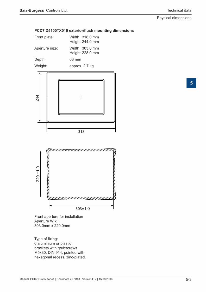
PCD7.D5100TX010 exterior/flush mounting dimensionsFront plate: Width 318.0 mm Height 244.0 mm
Aperture size: Width 303.0 mm Height 228.0 mm
Depth: 63 mm
Weight: approx. 2.7 kg
Front aperture for installation Aperture W x H 303.0mm x 229.0mm
Type of fixing: 6 aluminium or plastic brackets with grubscrews M5x30, DIN 914, pointed with hexagonal recess, zinc-plated.
���
���±1.0
244
229
±1.0

Manual: PCD7.D5xxx series | Document 26 / 843 | Version E 2 | 15.08.2006
Saia-Burgess Controls Ltd.
Physical dimensions
Technical data
5-4
5
PCD7.D5100TX010 dimensions:
���
�����
�
���
����
����
�������������������������������
�����������������������������
������������������������������������������ �������������

Manual: PCD7.D5xxx series | Document 26 / 843 | Version E 2 | 15.08.2006
Saia-Burgess Controls Ltd.
Electrical data/Environmental conditions
Technical data
5-5
5
5.2 Electrical data
Model PCD7.D5064TX010 PCD7.D5100TX010Power supplyOperating voltage 24 V ± 20%, reverse voltage protectedCurrent consumption approx. 1.0 AFuse 2.5 A slow-blowJumper time 1 ms at 19.2 V (Ub-20%)Display unitDisplay diagonal (inches) 6.4 10.4Active area (mm) 132.5x99.4 211.2x158.4Resolution (pixels) 640x480Max. colours 65536Viewing angle (H/V) 110°/90° 130°/110°Max. brightness (cd/m²) 400 430Contrast ratio 300 500Reaction time (25°C, tr/tf) 15/16 ms 10/30 msDisplay technology TFTService life (50% brightness) 30,000 hrs 50,000 hrsTouchscreen resistiveOperating temperature range 0 - 50°MemoryOperating system 64 MByte compact flash (external)Working memory 64 MByte SDRAM, 32 bitProcessor type Intel XScale PXA255, 400 MHzInterfacesSerial 1 RS232 for any useUSB 2x USB 1.1 (max. 0.5 A per port)LAN Ethernet 10/100 MBitReal-time clock Battery buffered, with date and calendar,
Precision 1 second
5.3 Environmental conditions
Ambient temperatureOperation 0 - 50° CStorage -20 - 60° CHumidity acc. to DIN EN60068-2-3Operation 10 - 75%, non-condensingStorage 10 - 95%, non-condensingVibration in operation acc. to DIN EN60068-2-6
0.075 mm (10 - 58 Hz), sine 1G (58 - 500 Hz), sine
Shock in operation acc. to DIN EN60068-2-27
15 g, 11 ms, half-sine
Protection type acc. to DIN EN60529
Front IP 65, back IP 20

Manual: PCD7.D5xxx series | Document 26 / 843 | Version E 2 | 15.08.2006
Saia-Burgess Controls Ltd.
Interfaces
Technical data
5-6
5
5.4 Interfaces
Compact flash slot: The PCD7.D5xxx units are fitted with a CFA standard (type 1) compact flash slot as standard.
Compact flash slot COM 1 Ethernet USB 1 USB 2
Only compact flash cards from SANDISK and SIMPLETECH should be used in conjunction with PCD7.D5xxx devices.
The compact flash card should only be changed with the device switched off.
Serial port (COM 1) The serial port is configured to the PC XT/AT standard. The interface is not electrically isolated.
Pin assignment of 9-pole D-Sub connector:
USB ports Both USB ports conform to the USB 1.1 standard and support a data transfer rate of 10 MBit/s.
A maximum current of 0.5 A may be taken from the two USB ports. External USB devices that need a higher supply current must provide it themselves.
●●●●●
●●●●
�� ����� ����� ����� ����� ��������
���� ����� ����� ���� �

Manual: PCD7.D5xxx series | Document 26 / 843 | Version E 2 | 15.08.2006
Saia-Burgess Controls Ltd.
Battery changing / Replacing background lighting
Maintenance and support
6-1
6
6 Maintenance and support
6.1 Battery changing
The devices are fitted with an integrated lithium battery for data buffering.
Battery type: Coin cells CR2032, 3V / 230mAh Manufacturer: e.g. Varta, type 6032 Buffer current: 2 µA typ. / 15 µA max. Battery voltage monitoring: yes (functionality dependent on software) Battery life (typ.): 5 years
Battery life is basically dependent on the prevailing environmental conditions (operating temperature, switch-on/switch-off time, humidity). The lifetime given here assumes that the device is switched on regularly (several times a week / at least 1500 hours a year).
The battery should only be changed by trained specialists. ESD protective measures should be observed.
Before changing the battery, the device should be disconnected from the power supply.
The PCD7.D5xxx units do not have to be taken out of the switching cabinet. It is sufficient to loosen the two screws on the back plate (hexagonal recess, size 2.0) and open the back plate downwards. Hold the back plate roughly horizontal with one hand.
Push the battery contacts back with a plastic object (e.g. touch stylus) until the battery pops out of the holder. Remove the battery. Insert new battery into the battery holder and clip in place. The positive pole of the battery must point upwards / be visible.
When the battery is changed, the real-time clock data will be lost.
Do not short-circuit the battery contacts. Risk of explosion. Battery should only be replaced with the same type from the same manufacturer.
Lithium batteries are hazardous waste. Used batteries should be disposed of in accordance with national guidelines.
6.2 Replacing background lighting
It is advisable to allow Saia-Burgess Controls AG to replace the tubes for the background lighting. The projected lifetime of the tubes can be found in the Technical Data.
The tubes for the background lighting contain traces of mercury and are hazardous waste. They must be disposed of in accordance with national guidelines.

Manual: PCD7.D5xxx series | Document 26 / 843 | Version E 2 | 15.08.2006
Saia-Burgess Controls Ltd.
Cleaning / Usage instructions for touch screens
Maintenance and support
6-2
6
6.3 Cleaning
Only mild cleaning agents should be used to clean the front of the unit (e.g. neutral soap solution or dilute washing-up liquid). Always use a clean, soft cloth for cleaning.
Do not use any cleaning agents that contain granules (e.g. scouring powder or cleansing milk). These may affect the readability of the display or damage the touch screen.Do not use acetone or benzene.
6.4 Usage instructions for touch screens
The touch screen should only be operated with the hand or a specially designed touch stylus. Using sharp metal objects (e.g. screwdrivers) may damage the touch screen.
Manual: PCD7.D5xxx series | Document 26 / 843 | Version E 2 | 15.08.2006
Saia-Burgess Controls Ltd.
Icons
Appendix
7-1
7
7 Appendix
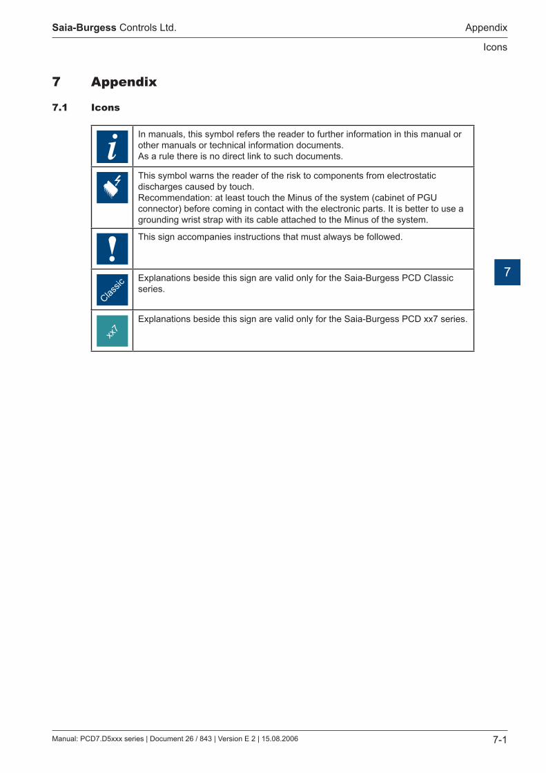
7.1 Icons
iIn manuals, this symbol refers the reader to further information in this manual or other manuals or technical information documents. As a rule there is no direct link to such documents.
This symbol warns the reader of the risk to components from electrostatic discharges caused by touch. Recommendation: at least touch the Minus of the system (cabinet of PGU connector) before coming in contact with the electronic parts. It is better to use a grounding wrist strap with its cable attached to the Minus of the system.
This sign accompanies instructions that must always be followed.
Classic
Explanations beside this sign are valid only for the Saia-Burgess PCD Classic series.
xx7
Explanations beside this sign are valid only for the Saia-Burgess PCD xx7 series.

Manual: PCD7.D5xxx series | Document 26 / 843 | Version E 2 | 15.08.2006
Saia-Burgess Controls Ltd.
Address
Appendix
7-2
7
Address of Saia-Burgess
Saia-Burgess Controls AG
Bahnhofstrasse 18 CH-3280 Murten / Switzerland
Tel: +41 26 / 672 71 11 Fax: +41 26 / 672 74 99 E-mail: [email protected] Home page: www.saia-burgess.com Support: www.sbc-support.ch