2.5’ x 5’ units - the neel company€¦ · construction manual 2.5’ x 5’ units | 8328-d...
TRANSCRIPT

CONSTRUCTION MANUAL2.5’ x 5’ UNITS
www.neelco.com | 8328-D Traford Lane, Springfield, VA 22152 | 703 913 7858

T-WALL® Construction Manual v7.05 © 2012 The Neel Company
The T-WALL® Retaining Wall System is Patented
CONSTRUCTION MaNUal
CoNTeNTSPart I EARTHWORk ......................................................................................................... 1 • The STrucTure dependS on iT!
Part II GENERAL OvERvIEW ........................................................................................ 2 • Work to be performed by the contractor ............................................... 2 • Basic construction procedures .................................................................. 2 • crew Size and production rates ................................................................ 2 • Materials & Services supplied by The neel company and/or the Licensed Producer ................................................................................... 2 • equipment, Materials and Tools Supplied by the contractor ......... 2 Part III CONSTRUCTION PROCEdURES ...........................................................3 - 10 • Site preparation ............................................................................................... 3 • Leveling pad construction ........................................................................... 4 • T-WALL® unit delivery ................................................................................... 5 • Lifting the units ............................................................................................... 5 • Layout on the Leveling pad ......................................................................... 6 • erection of the First course ......................................................................... 6 • constructing Subsequent courses and Backfilling ........................ 7-9 • Staged construction ....................................................................................10
Part Iv CONSTRUCTION dETAILS .................................10 - 12 & inSide BAck cover
• Terraced Walls & culverts ...........................................................................10 • Barriers & corners ........................................................................................11 • Fences, railings & integration with Structures ...................................12 • pipes, Basins & utility poles .............................................. inSide BAck cover
NOTE TO THE READERThis manual has been prepared as a guide to building T-WALL® Retaining Wall structures. Its contents should be thoroughly reviewed by the contractor and the superintendent responsible for construction prior to the delivery of the T-WALL® units to the job site. The Neel Company and/or its Licensed Producers will pro-vide job site technical assistance to help the contractor implement correct construction procedures. Com-pliance with this manual does not relieve the Contractor of the responsibility to adhere to contract plans and specifications. The T-WALL® Retaining Wall System should never be built without drawings stamped by a Professional Engineer.
Copies of the T-WALL® Construction Manual can be downloaded from www.neelco.com
T-Wall® Retaining Wall System

© 2012 The Neel Company T-WALL® Construction Manual v7.05
EARTHWORK – THE STRUCTURE DEPENDS ON IT! PART I
• FOundATIOn – The foundation should be inspected and approved by the owner’s engineer before the leveling pad is poured. if the founda- tion is soft, the wall will settle.
• SElEcT bAcKFIll gRAdATIOn And dEnSITY – This is critical to the structure’s stability. See the T-WALL® shop drawings for project backfill grada- tion and density. it is important that gradation tests be performed throughout construction to ensure that the backfill meets the specifications. The select backfill gradation affects the friction on the stems, drainage and settlement.
• cOmPAcTIOn – Proper compaction of the back- fill between and behind the stems is required to prevent settlement which will affect paving at the top of the wall. compaction tests are required throughout construction.
The following earthwork items are critical:Single Unit
double Unit
Specificationsare printed on the
T-WALL® shop drawings. Failure to meet the
specifications of any of the above items may
result in wall movement.
1
The concrete T-WALL® units are only half of the structure; the earth is the other half. This combination makes
the wall stand up.
T-WAll® unIT WEIgHTSStem Length
(ft)Single unit Weight (#)
double unit Weight (#)
6 1850 37008 2100 4200
10 2350 475012 2600 5250
14 2900 575016 3150 625018 3400 675020 3650 735022 3925 785024 4200 830026 4450 885028 4700 935030 4975 9850

T-WALL® Construction Manual v7.05 © 2012 The Neel Company
• WORK PERFORmEd bY THE cOnTRAcTOR: • Site preparation, including excavation • Forming and pouring the leveling pad • Wall construction including backfilling • Testing: backfill gradation and compaction • installation of fences, guardrails or other necessary items
• cREW SIZE: A typical wall erection crew includes: • one operator for excavator/crane for setting units & backfill placement • one working foreman to check alignment • Two men for setting units, placing joint materials, spreading and compacting backfill • one front-end loader and operator to deliver backfill and T-WALL® units • EQUIPMENT, MATERIALS AND TOOLS SUPPLIED bY THE cOnTRAcTOR: • T-WALL® unit lifting equipment: backhoe or small crane. • equipment for hauling, dumping and spreading backfill: dump trucks, front-end loaders and dozers. • compaction equipment: small walk-behind vibratory roller or plate compactor • Tools: • Lifting device & rigging • chalk line • Four-foot carpenter’s level • Surveyor’s level to check grade • Shims • crow bars & pinch bars • duct tape (for shear keys and filter cloth) • Broom to sweep leveling pad • power drill (10” x 3/4” carbide bit for drilling bolt holes in corner units) • 3/8” rod for gauging vertical joints
• PROducTIOn RATES: • construction rates for T-WALL® depend upon the site access and rate at which select backfill can be delivered, placed and compacted.
2
PART II gEnERAl OVERVIEW
• BASIC CONSTRUCTION SEQUENCE: • prepare the foundation • Form and pour leveling pad • Set first course of units • place and compact select backfill • place joint material and shear keys • Set subsequent courses of units
Setting the first course on the leveling pad
• MATERIALS AND SERVICES SUPPLIED BY THE nEEl cOmPAnY And/OR THE lIcEnSEd PREcAST mAnuFAcTuRER: • engineering and design of the structure • on-site technical assistance • delivery of the following wall materials to the site: • precast concrete T-WALL® units • Filter fabric for vertical T-WALL® joints • Shear keys • Shear key wrap material • horizontal joint material • connection hardware (when required by the design)

© 2012 The Neel Company T-WALL® Construction Manual v7.05
• excavate the site to the elevation shown on the contract plans for the entire footprint of the T-WALL® structure (including the area covered by the select backfill between the stems). under special cond- tions, the excavation may be done in increments to minimize the amount of open cut.
• proof roll and inspect the foundation in accordance with the project specifications.
• All unsuitable materials below subgrade must be removed and replaced with select, compacted backfill at the direction of the owner's engineer.
• Foundation is to be inspected and approved by the owner/ owner’s engineer for required bearing capac- ity as shown on the approved T-WALL® drawings.
• Where possible the width of excavation should allow sufficient room to set the longest stem with some space behind the stem to access the space between the stems.
• excavate for the leveling pad.
• Any under-drains, drainage piping or drainage blankets should be installed at this time.
cOnSTRucTIOn PROcEduRES PART III
SITE PREPaRaTION:
3
Preparing the site
Typical Vertical T-WALL® Section
Compaction of the soil prior to placing units drain inlet between stems

T-WALL® Construction Manual v7.05 © 2012 The Neel Company 4
PART III cOnSTRucTIOn PROcEduRES (continued):
STEPPEd lEVElIng PAd:
• Steps in the Leveling Pad - Construct the lower leveling pad. Leave a 6 to 8" gap before con- structing the higher pad. This gap will assure that the higher pad does not interfere with the placement of the units on the lower pad.
Stepped leveling pad
lEVElING PaD CONSTRUCTION:
• The leveling pad is typically 12 inches wide and a minimum of 6 inches deep unless otherwise shown on the wall drawings.
• For a vertical wall, the typical step (change in elevation ) is 2'-6 1/2" for standard units or 5'-1" for double height units (top of pad to top of pad).
• For a battered wall - ask for/or download a T-WAll® battered Wall Supplement.
• Pour the leveling pad. The concrete surface finish must be smooth and flat.
• check the leveling pad for line, grade and tolerance with an instrument level. • if the leveling pad is out of tolerance, make correc- tions at this time. An out of tolerance pad will slow down the installation rate.
• check for alignment. The front edge of the pad should be 3" out side the front face line of the wall.
• The leveling pad is for construction alignment only. The concrete may be low strength, 2,500 psi and there is no rebar in the leveling pad.
• The leveling pad shall be cured for 24 hours prior to installation of T-WALL® units.
• Form the leveling pad similar to forming a side- walk. The edge forms are the screed rail. They must be checked with a level to assure proper elevation and tolerance. Top of leveling pad elevation shall be + 1/4 inch in any 10 foot length.
• contractor must take corrective action or plan to shim the first course to the highest point. Shim- ming will greatly increase the installation time of the first course.

© 2012 The Neel Company T-WALL® Construction Manual v7.055
• under normal circumstances, a two hour unload- ing time is allowed for each delivery. During this period of time, the units may be unloaded and stacked on the ground. if the time allows, the units may be placed directly into the wall structure.
• care must be exercised during handling to protect the units and joint materials from damage. Do not stack units more than two high.
• dunnage and plastic edge guards are the property of the precast Manufacturer and must be collected and returned as soon as possible.
• if the units are precast with lifting inserts the contrac- tor will provide his own lifting devices. The lifting devices are to be compatible with the lifting inserts specified in the approved shop drawings.
• if the units are precast without lifting inserts the contractor may be loaned, upon agreement, a lifting device: • The lifting device must be kept in good working order for safe lifting. • if the device has excessive wear or broken parts, dO nOT uSE. Contact the Licensed precast Manufacturer and/or The neel Company for a replacement device.
• it is the contractor’s responsiblity to see that the lifter(s) is returned to the Precast Manufacturer.
• if the device is lost, damaged or stolen the contrac- tor will be responsible for the cost of the device.
Unloading units from truck
Lifting a long unit at the balance points
(continued) cOnSTRucTIOn PROcEduRES PART III
• prior to the start of construction, the contractor and The Neel Company or the Precast Manufacturer shall develop a schedule for material deliveries. This time- table will allow the producer to match unit produc- tion with the construction schedule.
T-Wall® UNIT DElIVERY:
UNlOaDING THE UNITS:
Lifting a double unit which was precast with lifting inserts
LIfTING THE UNITS:
LIfTERS: for units without lifting inserts stem lengths 6’ – 14’ use 1 lifterstem lengths 16’ & up use 2 lifters

T-WALL® Construction Manual v7.05 © 2012 The Neel Company 6
First course of units on leveling pad
• Always begin erection at a fixed point such as a corner, step, or tie-in to an existing structure. if there is no fixed point, simply start on the lowest leveling pad. use gauges to hold the 3/8" vertical space between units. A smooth 3/8" steel rod 18" long with a handle works best. continually check the horizontal dimensions to ensure that the verti- cal joints can be held within tolerance.
• Joint material is not required between the level- ing pad and the precast units.
• Set the first units on the leveling pad, using the chalk line as a guide for aligning the front face.
• Adjust the elevation of the back of the stem to plumb the front face of the unit. it is critical to the wall alignment that the bottom course of units be plumb.
• After aligning the front face, check the top of the front face for level and height with relation to the other units in this course. if the top of the unit is irregular, place the level on the line where the top of the front face is chamfered. Shim as necessary. rechecking alignment, level and plumb to make sure that you have not disturbed one unit while adjusting the other.
• periodically, before backfilling, step back and sight down the tops of the units. This visual check will allow you to fine tune the alignment.
• every effort should be made to ensure that the first course of units is properly aligned and level.
• construct the wall in horizontal courses.
• To establish wall alignment, snap a chalk line on the surface of the leveling pad to coincide with the survey line of the front face of the wall. This will be the front face of the wall and will center the unit on the leveling pad. Mark critical linear dimension points such as chords or angle points. (contractor may nail 2x4’s along the line to act as a guide for alignment.)
• Grade and compact the subgrade material level with the top of the pad the full length of the stems so that the front face of the units will be plumb. After a unit is set, it is much easier to shim the stem up than to excavate down; therefore it is better to be low than high in this operation.
laYOUT ON THE lEVElING PaD:
ERECTION OF THE FIRST COURSE:
PaRT III CONSTRUCTION PROCEDURES (continued)
Board nailed on leveling pad to act as guide
checking alignment

© 2012 The Neel Company T-WALL® Construction Manual v7.05
Filter fabric covering vertical joints on back face of top units
7
Filter fabric placement
• prior to initial backfilling, the 12" wide filter fabric should be cut into lengths equal to the height of the wall at each vertical joint. • center these strips across the 3/8" vertical joints between the units at the rear face. This procedure prevents the migration of the backfill material through the joints.
• Throw the excess filter fabric over the top of the units during backfilling and pull it back on the backfill during setting opera- tions.
• horizontal joint material is placed in the hori- zontal joints between the units at the face.
• This material acts as a cushion to prevent concrete-to-concrete contact and as a gasket to prevent backfill material leakage.
• position the horizontal joint material so that it is flush with the rear face of the unit.
• Shear keys, wrapped twice with the provided shear key wrap, should be placed in the space between teeth where the top and bottom stems come together.
• The number of keys required per unit is shown in the actual section(s) on the T-WALL® drawings for the project. Location of the keys is not critical. place one in the front and one in the last block- out and then equally space the remainder in between.
• The purpose of the shear keys is to: – provide an alignment guide – prevent movement of the unit during backfilling and compaction – provide additional pullout resistance at the top of the wall.
(continued) cOnSTRucTIOn PROcEduRES PART IIICONSTRUCTING SUBSEQUENT COURSES aND BaCKFIllING:
Horizontal joint material and shear keys in shear key wrap

T-WALL® Construction Manual v7.05 © 2012 The Neel Company 8
• it may be necessary to plumb the units using shims between the stems at the back of the units. Shims may be small pieces of standard asphalt shingles, plastic or wood.
• if you encounter a unit that is out of square it is best to use the face as a guide to alignment. keep in mind that this is purely an aesthetic concern, not a structural problem. however, difficulties with plumbing and alignment should be reported to The neel company.
• vertical tolerance (plumbness) and horizontal alignment tolerance as the wall is constructed shall not exceed + 3/4 inch when measured with a 10 foot straight edge.
• The overall vertical tolerance of the wall (plumbness from top to bottom) shall not exceed + 3/4 inch per 10 feet of wall height (for vertical walls).
Walls have a tendency to groW or shrink in length depending on the amount of care taken to properly layout and align the first course!
PART III cOnSTRucTIOn PROcEduRES (continued)
CONSTRUCTING SUBSEQUENT COURSES aND BaCKFIllING:
PLUMbING ANd ALIGNMENT
Placing top units into position
Select backfill (material used between the T-WALL® unit stems)• Must meet project specifications for gradation, unit weight and Ø value unless otherwise specified.• Granular material with 100% passing 3” screen, and maximum 25% passing no. 200 seive• Minimum angle of internal friction (Ø) of 32°• Typical unit weight ranges from 105 to 125 pcf• Material can be sand, gravel, crushed rock, re- cycled concrete and aggregate blends• other materials may be considered based on availability, special design requirements (e.g. lightweight fills) or other factors.
unclassified backfill (material used behind the T-WALL® units)• Must meet project specifications for grada- tion, unit weight and Ø value unless otherwise specified.• Minimum angle of internal friction (Ø) of 30°• Typical density range from 105 to 125 pcf
compaction requirements (for both select and unclassified backfill)• Should be performed with heavy vibratory equipment sized to ensure proper compaction is achieve throughout each backfill zone (both select and unclassified)• Minimum 95% Standard proctor density as determined by ASTM-698 (AAShTo T-99)• For materials where on-site compaction testing is not practical, compaction shall be carried out until there is no movement of the backfill materials.
bACkfILL
© 2012 The Neel Company T-WALL® Construction Manual v7.059
• Backfill each course to within 6” of the top of the stem before setting the next course of units.• do not stack units more than one unit high without backfilling. Doing so may cause units above to shift creating safety hazards, and require resetting of units.• Improper backfilling can result in post con- struction settlement of the backfill, poor wall performance, or wall instability.• unclassified backfill behind the wall should be placed and compacted at the same rate as the wall section, with maximum of 1 course differ- ential between fill levels.• Backfilling and compaction at the face of the wall should take place as soon as possible, and should be done once the wall has reached a maximum of 10 feet in height.
PART III cOnSTRucTIOn PROcEduRES (continued)
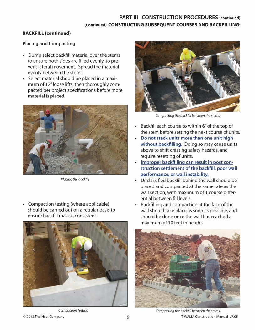
Compacting the backfill between the stems
(Continued) CONSTRUCTING SUBSEQUENT COURSES aND BaCKFIllING:
Compaction Testing
bACkfILL (continued)
Placing the backfill
Compacting the backfill between the stems
Placing and compacting
• dump select backfill material over the stems to ensure both sides are filled evenly, to pre- vent lateral movement. Spread the material evenly between the stems.• Select material should be placed in a maxi- mum of 12” loose lifts, then thoroughly com- pacted per project specifications before more material is placed.
• compaction testing (where applicable) should be carried out on a regular basis to ensure backfill mass is consistent.

T-WALL® Construction Manual v7.05 © 2012 The Neel Company 10
STaGED CONSTRUCTION:• T-WALL® should be constructed horizontally, one course at a time.
however, there are some situations where staged construction may be necessary.
• Be aware that if the vertical height difference between adjacent columns is greater than one unit, the vertical joints will open due to the unbalanced earth pressure.
(continued) cOnSTRucTIOn PROcEduRES PART III
In order to avoid problems with the wall alignment, you must contact The Neel Company for specific instructions whenplanning for staged construction.
TERRaCED WallS
PART V cOnSTRucTIOn dETAIlS see contract drawings for project specific details
T-WALL® ON TOP Of CULvERT

© 2012 The Neel Company T-WALL® Construction Manual v7.0511
BaRRIERS
Flush mounted barrier
Barrier designed with a lip that extends over the top of the wall
(see contract drawings for project specific details) cOnSTRucTIOn dETAIlS – PART V
CORNERS
units have half stems allowing the courses to alternate direction.
Corner with bolted connection
Alternating direction of stem
Field installed connection as shown on the approved drawings.

T-WALL® Construction Manual v7.05 © 2012 The Neel Company 12
PART V cOnSTRucTIOn dETAIlS see contract drawings for project specific details
RAILING dETAIL
GUARd RAIL
CHAIN LINk fENCE
T-WALL® INTEGRATION WITH OTHER STRUCTURES

© 2012 The Neel Company T-WALL® Construction Manual v7.05
LARGE PIPE PENETRATIONS
PIPE PARALLEL TO WALL fACE
note filler panel - which can be used to accommodate pipes, inlets, or other obstructions.
see contract drawings for project specific details – cOnSTRucTIOn dETAIlS PART V
CATCH bASIN UTILITY POLE bASES
T-WALL® Construction Manual v7.05 © 2012 The Neel Company
T-WALL® Retaining Wall System
Construction Manual
The Neel Company8328 Traford Lane Ste. DSpringfield, VA 22152
703-913-7858 ph.703-913-7859 fax
w w w.neelco.com