25% decathlon assembly manual - bill hempel · 25% decathlon assembly manual thank you for...
TRANSCRIPT

25% Decathlon
Assembly Manual
Thank you for purchasing a Bill Hempel Team Edge aircraft.
We strive to build high quality and great flying aircraft. We have

2
used our years of experience in the hobby to design and build
aircraft that are competitive at the highest levels of aerobatic
competitions and that will last for many flying seasons.
We suggest that you read through the manual before starting the
assembly. If you have any questions or concerns please don’t
hesitate to e-mail us at [email protected]
Thank you
Bill Hempel
Billhempel.com assumes no liability for any damage resulting
from the user assembled product. By the act of using the assembled
product, the user accepts all resulting liability. The purchaser or
designated person flying this aircraft accepts all liability associated
with the use of this product. This product is sold as is and the
purchaser accepts any and all responsibility for structural or
mechanical failures. Because of the stresses that are associated
with aerobatic flight there is no warranty provided and
bill.hempel.com cannot be held liable.
WARNING:
Radio Control Model aircraft are not toys. If improperly used, it can
cause serious injury or death. Fly only in open areas, and at AMA
(Academy of Model Aeronautics) approved flying sites. The AMA
Safety Code must be followed. Follow all instructions included with
your plane, radio, and engine. The purchaser accepts all liabilities.
3
SPECIFICATIONS:
Wingspan: 100”
Length: 70”
Wing area: 1615 sq. inches
Weight: 14.5-15.5 pounds
Engine: 30cc-50cc
Servos: 6 minimum
Miscellaneous Needed:
Various Hand tools
Drill and drill bits
Rotary tool & sanding drum
Heat Gun
Hobby Knife
Medium Thread locker
Silicone Adhesive or Canopy Glue
30 Minute Epoxy
JB Weld
3/8” Heat Shrink Tubing
Cardstock
Sharpie
Ink Pen

4
Additional Items Needed:
30cc to 50cc single cylinder engine
Muffler
Propeller (Engine manufacturer recommended)
3.5” Spinner
Appropriate sized spinner bolt
12-24 ounce Fuel Tank & Gas Fuel Line
Radio 6 channel minimum recommended
1 - 2.4 GHz receivers
2- Elevator servos 220 ounce of torque (minimum)
2- Aileron servos 220 ounce of torque (minimum)
1- Rudder servo 220 ounce of torque (minimum)
4 - 1” Aluminum Servo Arms (Ailerons & Elevators)
1 - 3”-4” Double Arm (Rudder)
1- Throttle servo
1- Receiver battery packs (2300 mAH minimum)
1- Ignition battery 1200 to 2300 mAH
2-Voltage Regulators (if needed)
2- Switches: 1 for receiver, and 1 for ignition
Servo extensions required:
Ailerons: 2 x 12”
Elevators: 2 x 36”
Rudder: Not required
Throttle: Not required

5
Unpacking:
Carefully remove the aircraft from the boxes and inspect for any
damage. If you have any damage it must be reported to the freight
company immediately. Billhempel.com is not responsible for any
shipping damage. You must contact the carrier. We will work with
the purchaser and the freight company to resolve any issues.
However a claim must be filed before we can begin the process.
Re-shrink the Covering:
Before doing any assembly or installation it is very important to re-
shrink or retighten the already applied covering. Due to the
shipping process, heat and humidity changes from different
climates, the covering may become lose and wrinkle in the sun. If
you take the time to re-tighten the covering, you will be rewarded
with a long lasting beautifully covered model. Using your
covering iron with a soft sock, gently apply pressure and rub in the
covering. If any bubbles occur, your iron may be too hot. Reduce
heat and work slowly. You should be able to just see the wood
grain under the covering when proper adhesion has occurred.
IMPORTANT:
Go over any and all seams and color overlaps with your iron to
assure good adhesion of the covering to the wood. This is
especially important at the leading edges of the wings and stabs
and all overlapping material.

6
Once all seems have been ironed down, then use a heat gun
with extreme caution. Be careful; don’t apply too much heat to
one area for long periods of time. This may cause the trim
colors to over shrink and pull away leaving unsightly gaps on
the color lines. The trim stripes are especially vulnerable to
over shrinking. Tightening and re-shrinking the covering is
now complete.
Getting Started:
Using a hobby knife or soldering iron, carefully remove the
covering from the areas shown below.

7

8

9

10

11

12
Landing Gear Installation:
In the landing gear hardware bag you will find four socket head
cap screws, flat washers, and lock nuts for mounting the landing
gear. The landing gear is installed with the gear swept slightly
forward.

13
Install the axles

14

15
The landing gear cover is held in place with a small amount of
silicon adhesive. Apply the adhesive in a few spots on the front
and rear edge of the cover.

16
Tail Wheel Installation:
Place a flat washer on each screw and then apply thread locker to
the screws. Mount the carbon fiber tail wheel bracket on the
fuselage.
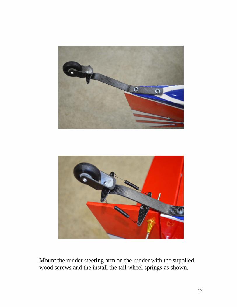
17
Mount the rudder steering arm on the rudder with the supplied
wood screws and the install the tail wheel springs as shown.

18
Horizontal Stab Installation:
The horizontal stabilizer is glued in place with 30 minute epoxy.
Take measurements on both sides of the stab to make sure that it is
centered in the fuselage. Install both wings on the fuselage and
then measure from the trailing edge of the wings to the trailing
edge of the stab to insure that the elevator hinge line is square to
the wings. A square is used to make sure that the horizontal
stabilizer is square to the vertical stabilizer.

19
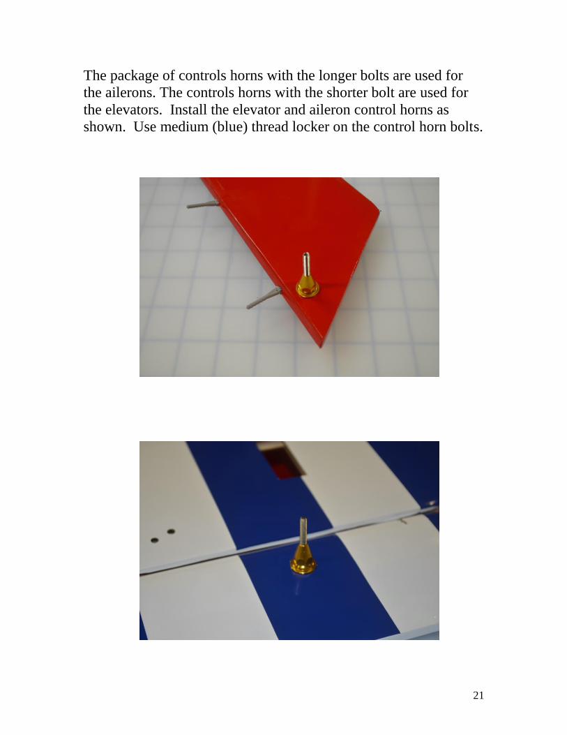
Control Horn Installation:

20
Install the rudder control horn as shown. Use medium (blue)
thread locker on the control horn bolt. Make sure that the control
horn bolt is centered in the rudder.
21
The package of controls horns with the longer bolts are used for
the ailerons. The controls horns with the shorter bolt are used for
the elevators. Install the elevator and aileron control horns as
shown. Use medium (blue) thread locker on the control horn bolts.

22
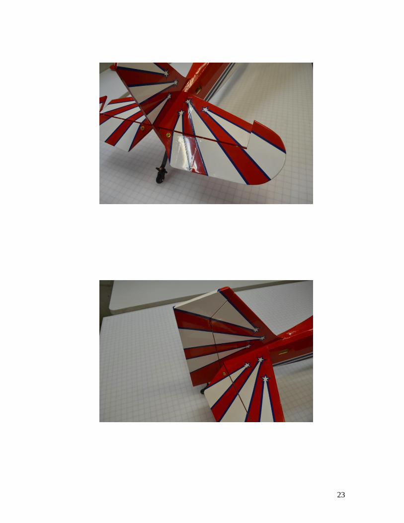
Elevator and Rudder Installation:
The holes for the hinges have been pre-drilled at the factory. Use
30 minute epoxy or gorilla glue to install the hinges in the
elevators and rudder. Once the adhesive has fully cured glue the
control surface in place on the airframe.
23

24
Tail Wire Installation:
The parts for the tail wires are located in the package labeled Stab.
Bend each bracket to a 45 degree angle and then bolt the brackets
in place on the horizontal and vertical stabilizers as shown. The
bolt goes through the bracket and then through the hole in the stab,
then the second bracket is held in place with a locknut.

25
Assemble the tail wires as shown below. Use a crimping tool to
secure the wires.

26

27
Install the 4 tail wires as shown. The wires should be snug but still
have a slight amount of play in them.

28
Aileron Servo Installation:

29
Attach a 12” servo extension to each aileron servo. Use a 2” piece
of 3/8” heat shrink tubing or plastic safety clips to secure the
connection.
Install the servos and secure them with the servo screws that are
supplied with the servos, or use 9/16” socket head servo screws.
30
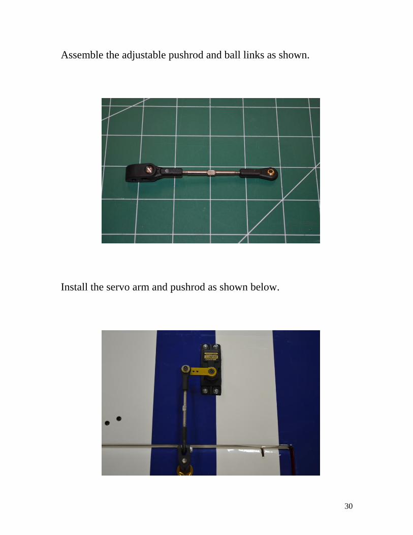
Assemble the adjustable pushrod and ball links as shown.
Install the servo arm and pushrod as shown below.
31
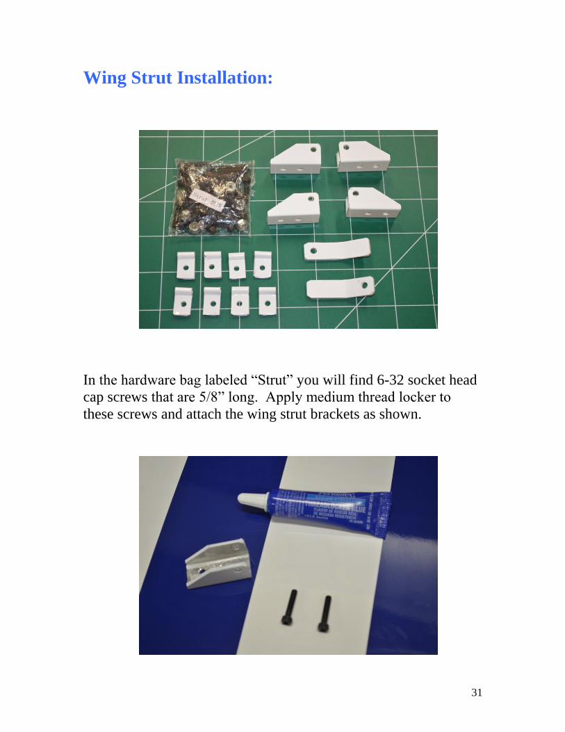
Wing Strut Installation:
In the hardware bag labeled “Strut” you will find 6-32 socket head
cap screws that are 5/8” long. Apply medium thread locker to
these screws and attach the wing strut brackets as shown.
32

33
Install the strut support brace in place on the wing.

34
Bolt the wing struts together with a 5/8” long 6-32 cap screw and
locknut. The wing struts are airfoil shaped, make sure that the
leading edge of the airfoiled struts are facing forward. The struts
are hollow, be careful to not crush the struts when tightening the
bolts.
The 1” long 6-32 cap screws and locknuts are used to attach the
struts to the wing (see below.)

35
Use 5/8” long 6-32 cap screws and lock nuts to attach the braces to
the wing struts.

36
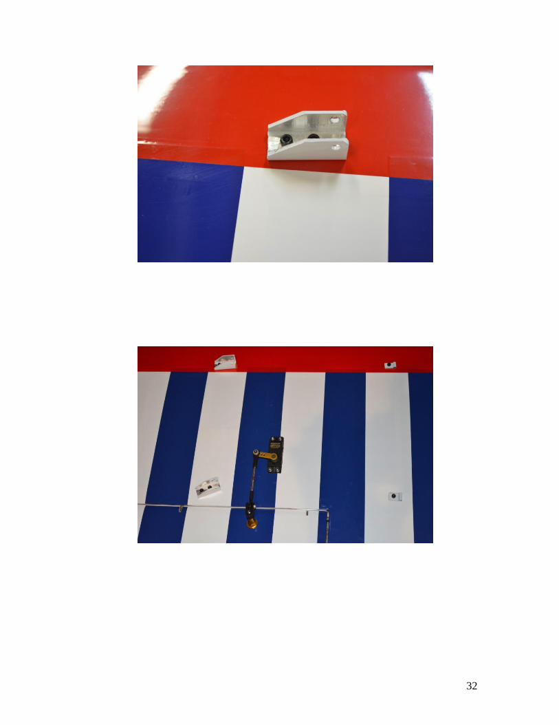
Install the strut attachment bracket in the fuselage as shown below,
use medium thread locker on the 5/8” 6-32 bolt.

37
38
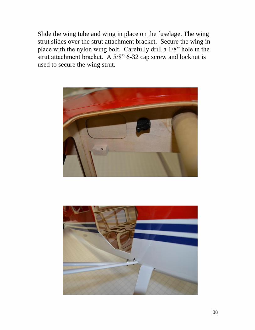
Slide the wing tube and wing in place on the fuselage. The wing
strut slides over the strut attachment bracket. Secure the wing in
place with the nylon wing bolt. Carefully drill a 1/8” hole in the
strut attachment bracket. A 5/8” 6-32 cap screw and locknut is
used to secure the wing strut.
39
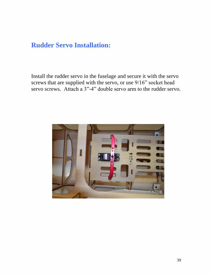
Rudder Servo Installation:
Install the rudder servo in the fuselage and secure it with the servo
screws that are supplied with the servo, or use 9/16” socket head
servo screws. Attach a 3”-4” double servo arm to the rudder servo.

40
Rudder Pull-Pull Cable Installation:
Run the pull-pull cables through the fuselage, the cables exit at the
rear of the fuselage. The cables cross inside the fuselage. The
cables are assembled just like the tail brace wires.

41

42
Elevator Servo Installation:
Connect a 36” servo extension to each elevator servo. Slide a 2”
piece of 3/8” heat shrink tubing over the servo connectors and
shrink it with a heat gun. You can also use a plastic servo safety
clip. Install the servos and secure them with the servo screws that
are supplied with the servos, or use 9/16” socket head servo
screws. Center the servo and install a 1” servo arm on each
elevator servo. Make sure to use medium thread locker on the
servo screw.

43
Elevator Pushrod Installation:
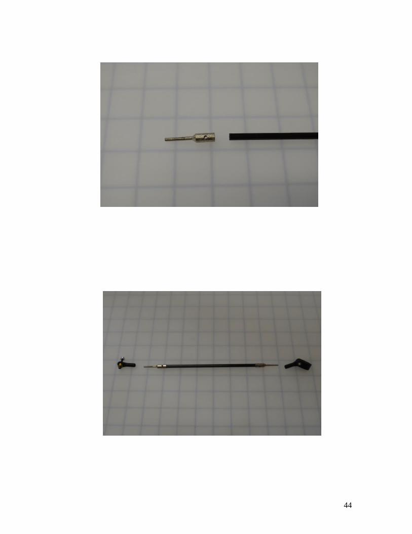
Carefully cut the Carbon Fiber rod into two 6 3/16” pieces.
Make sure to use personnel protective equipment when cutting
carbon fiber. Assemble the pushrods as shown below. JB Weld is
used to glue the carbon fiber rod into the threaded end pieces. Mix
the JB Weld per the instructions. Apply the JB Weld liberally on
the carbon fiber rod and inside the threaded end piece. When the
Carbon fiber rod is slid into the threaded end piece, JB Weld will
ooze out of the two holes in the threaded end piece. Clean up the
excess JB Weld with a paper towel. Use masking tape to secure
the end pieces while the JB Weld cures.
44

45
Once the JB Weld has fully cured assemble the pushrod as shown.
Install the pushrod as shown.
46
Engine Installation:

47
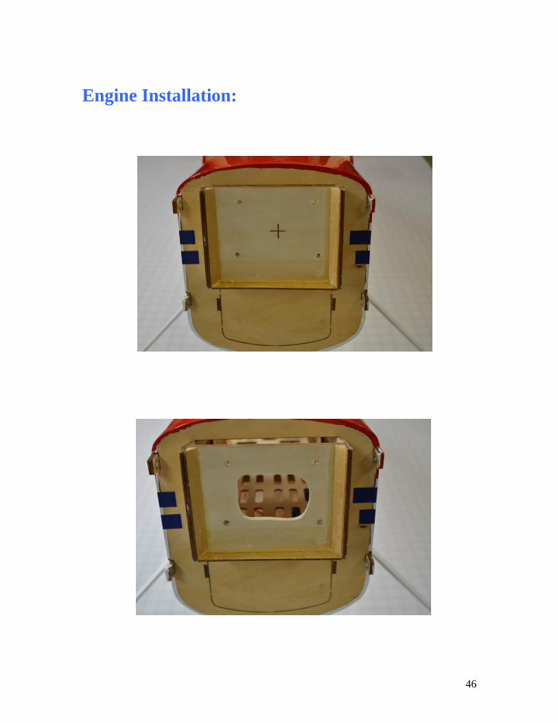
Tape or clamp the engine manufacturers mounting template in
place on the firewall. Drill four appropriate sized holes for
mounting your engine. Open a hole in the firewall for the throttle
linkage and fuel line to pass through.

48
The spacing from the firewall to the front of the cowling is 6 1/4”.
Select standoffs that provide the necessary spacing for your engine.
The standoffs that are included with a DLE-35RA fit perfectly. If
needed for other engine installations; ¼” washers can be used
between the firewall and the standoffs for adjusting the spacing
between the cowling and spinner.
The throttle servo is mounted inside the fuselage as shown below.

49
Throttle Pushrod installed.

50
Drill a hole in the bottom of the engine box for the spark plug wire
to pass through. Use either a rubber grommet on the hole, or
install plastic tubing on the spark plug wire to protect it from
chaffing.
The ignition unit and ignition battery are mounted inside the
fuselage. Place foam rubber under them, use hook and loop
material to secure them in place.

51

52
Fuel Tank Installation:
There is room inside the fuselage for up to a 24 ounce fuel tank.
Pictured is a 16 ounce Dubro tank which works well with the DLE-
35RA. Follow the fuel tank manufactures instructions for
assembling the fuel tank. The fuel tank is mounted on the
equipment tray. Place foam rubber under the fuel tank and use
hook and loop material to secure it in place. The fuel tanks vent
line exits through the bottom of the airframe.

53
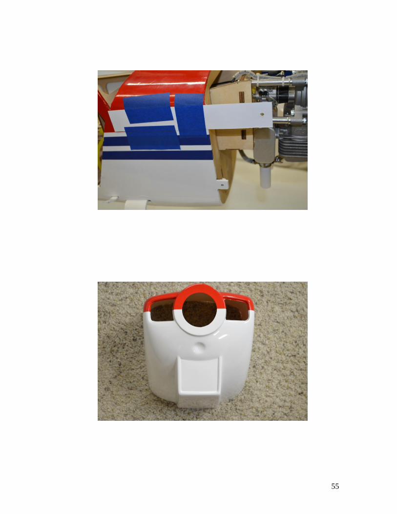
Cowling Installation:
The cowl is secured to the fuselage by the four tabs that are built
into the fuselage. Use card stock to make a template for the four
mounting locations in the cowl. Once the template is made;
remove the muffler from the engine, install the cowling, and then
use the template and a sharpie to mark the locations on the cowling
for the mounting holes. Remove the cowl and use a 1/8” drill bit
to drill the four holes in the cowl. A similar template can be made
for marking the opening for making needle valve adjustments, and
the muffler exit. A rotary tool with a cutoff wheel or a sanding
drum is used to make the openings for the muffler exits. Re-install
the muffler using blue thread locker on the muffler bolts. Also
apply blue thread locker to cowl mounting screws.

54
55

56

57
Spinner & Prop Installation:
A 3 1/4” or 3 1/2” Spinner is needed for the Decathlon. Pictured is
a 3 1/2” Tru-turn spinner. Use a propeller drill guide designed for
your engine to drill both the spinner’s back plate and the propeller.
Install the propeller and spinner according to the manufactures
instructions. Apply blue thread locker to the spinner bolt and prop
bolts.

58
Switches, Receiver, and Battery Installation:
There is plenty of room inside the fuselage for mounting the
switches and fuel dot. They are accessible through the pilot’s
door. They can also be installed on the outside of the fuselage if
desired. Place foam rubber under the battery and receiver to
protect them from shock and vibration. Hook and loop material is
used to secure the battery and receiver.
59
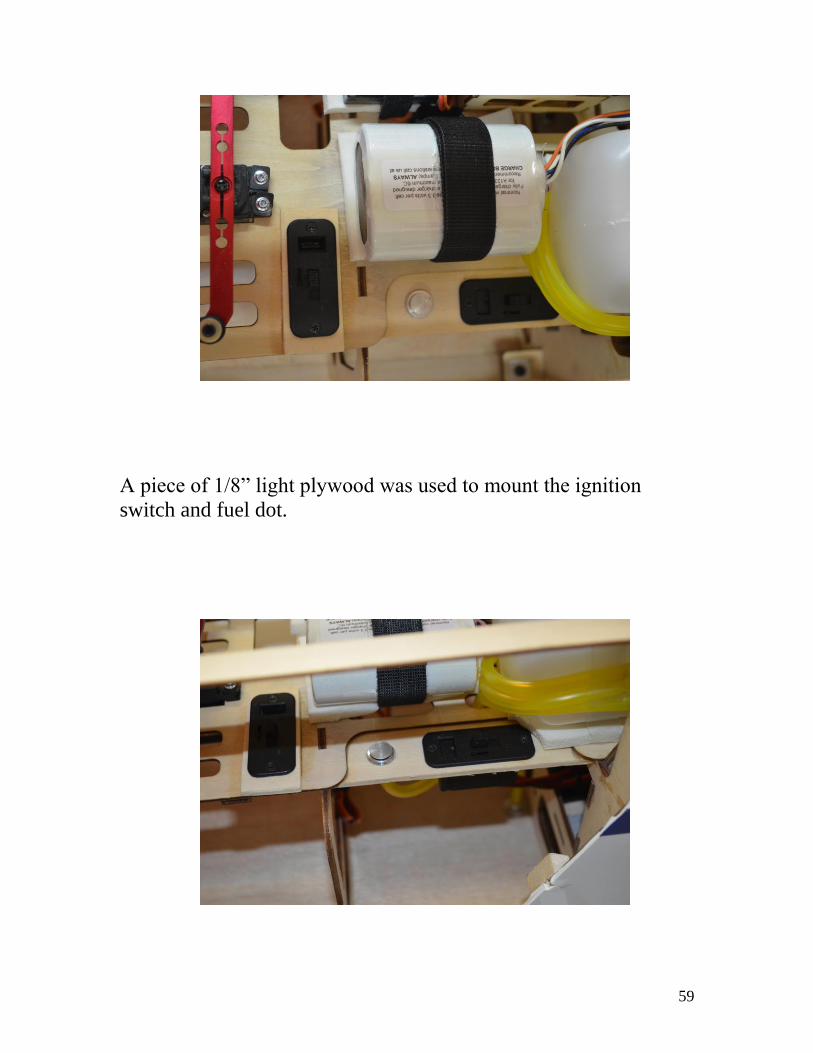
A piece of 1/8” light plywood was used to mount the ignition
switch and fuel dot.

60
Windows, Windshield, and Door Installation:
The windows are installed in each door. The windows can be
glued in place with canopy glue, clear silicon adhesive, or welders
contact cement. Remove the plastic protective covering off of the
side that is being glued into the opening. Once it’s glued in place,
then the protective plastic covering is removed from the outside of
the window. Be careful to keep the glue off of the windows. Glue
the rest of the windows in place on the fuselage.

61
62
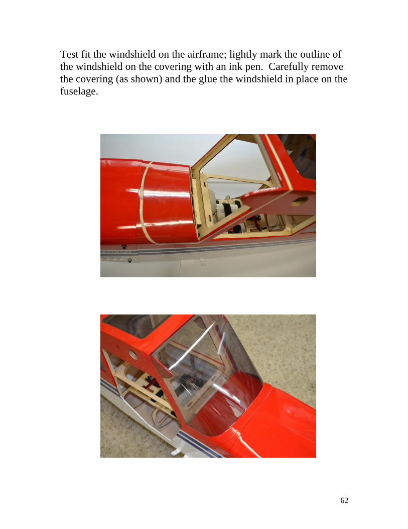
Test fit the windshield on the airframe; lightly mark the outline of
the windshield on the covering with an ink pen. Carefully remove
the covering (as shown) and the glue the windshield in place on the
fuselage.

63
Secure the hinges in the doors with 5-minute epoxy make sure that
you don’t get any epoxy in the joint portion of the hinge. The
doors are then glued in place on the fuselage. Make sure that the
doors are aligned correctly so that they open and close without
binding. Continue to check the alignment as the adhesive cures.

64
Install Wheels and Wheel Pants:
The last step in the assemble process is the installation of the
wheels and wheel pants. We save this step for last so that the
airplane doesn’t roll off of the workbench during the build.
65
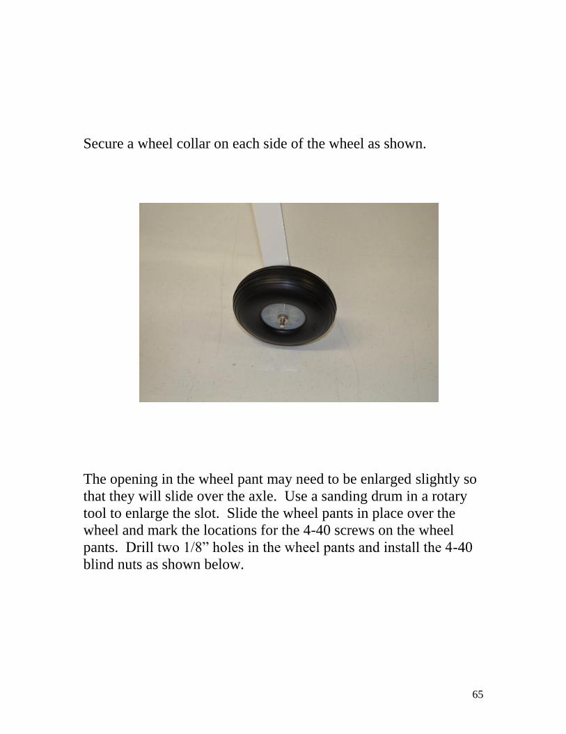
Secure a wheel collar on each side of the wheel as shown.
The opening in the wheel pant may need to be enlarged slightly so
that they will slide over the axle. Use a sanding drum in a rotary
tool to enlarge the slot. Slide the wheel pants in place over the
wheel and mark the locations for the 4-40 screws on the wheel
pants. Drill two 1/8” holes in the wheel pants and install the 4-40
blind nuts as shown below.
66
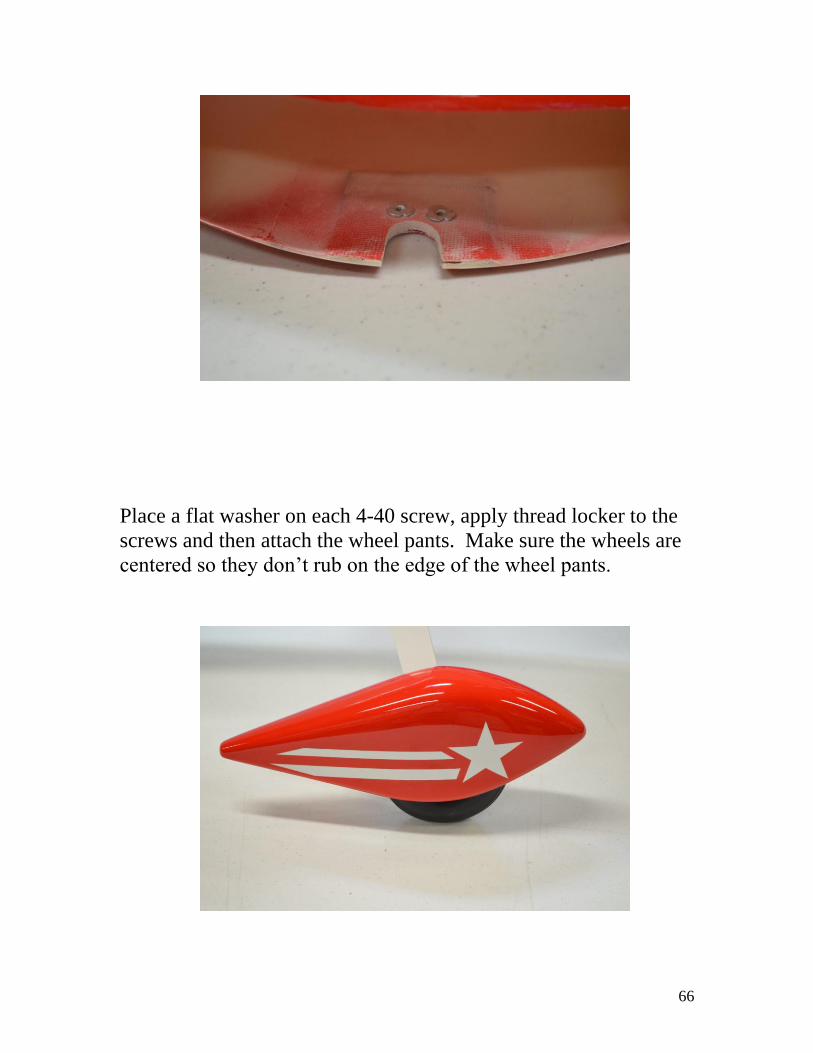
Place a flat washer on each 4-40 screw, apply thread locker to the
screws and then attach the wheel pants. Make sure the wheels are
centered so they don’t rub on the edge of the wheel pants.

67
Balancing:
Assemble the airplane ready to fly (minus fuel.) For the initial
flights balance the aircraft at 4” back from the leading edge of the
wing. Mark the locations at the wing tip and have a friend help
you lift the aircraft by the wing tips at this location. The aircraft
should balance level or slightly nose down. After initial flights the
C.G. can be adjusted to accommodate your flying style.
Control Surface Throws:
Place the airplane on a flat table. Make sure all control surfaces are
centered at neutral. Check to see that all control surfaces are
moving in the correct direction. Measure the control surface
throws using a degree meter or a straight edge (measured at the
trailing edge.) We used 35% expo on all control surfaces both on
low and high rates. Remember that Futaba radios use a negative
number on expo, and JR/Specktrum radios use a positive number.
Adjust the amount of expo and control surface throws to your
personal preference. These are the settings that we use.

68
ELEVATOR:
Low Rate: 15 degrees each direction (1.25” each direction)
High Rate: 33 degrees each direction (2.25” each direction)
AILERON:
Low Rate: 15 degrees each direction (1” each direction)
High Rate: 30 degrees each direction (1 3/4” each direction)
RUDDER:
Low: 20 degrees each direction (1” each direction)
High: 30 degrees each direction (1.5” each direction)
Pre-flight:
The engine should be properly adjusted and running smoothly and
should have a good throttle transition. If the engine isn’t running
properly don’t try flying the plane.
Perform a range check with the engine running. Make sure the
range check meets or exceeds the radio manufactures
recommendations.

69
Set the Fail Safe on the radio and the throttle cut per the radio
manufactures instructions.
Make sure the control surfaces are moving in the proper direction.
Check the batteries to make sure they are fully charged, and re-
check the batteries after each flight.
Make sure that you have used thread locker on all nuts and bolts.
We recommend using low rates for the initial test flights.
Have Fun, Enjoy your aircraft, and fly safe.