24930 03 ch03 105. - consulting...
TRANSCRIPT

SECTION
II
Create theBuilding Model©
Cen
gage
Lea
rnin
g. A
ll rig
hts r
eser
ved.
No
dist
ribut
ion
allo
wed
with
out e
xpre
ss a
utho
rizat
ion.

Most common words in Section II
The first step toward reaping the benefits of Building Information Modeling is toconstruct a virtual building model in the software. The tools provided for this pur-pose in Revit are many and varied. In this section we will explore the many buildingmodeling tools available such as Walls, Doors, Windows, Columns, Beams, Stairs,Railings, Roofs, Floors, and Curtain Walls. In Chapter 10, we will take a detailedlook at Revit Family Components and the Family Editor.
Section II is organized as follows:
Chapter 3 Creating a Building Layout
Chapter 4 Setting up Project Levels and Views
Chapter 5 Column Grids and Structural Layout
Chapter 6 Groups and Links
Chapter 7 Vertical Circulation
Chapter 8 Floors and Roofs
Chapter 9 Developing the Exterior Skin
Chapter 10 Working with Families
© C
enga
ge L
earn
ing.
All
right
s res
erve
d. N
o di
strib
utio
n al
low
ed w
ithou
t exp
ress
aut
horiz
atio
n.
CHAPTER
3
Creating aBuilding Layout
INTRODUCTION
Revit Architecture can be used successfully in all types of architectural projects andwithin all project phases. Most of our attention in this book is given to the design devel-opment and construction documentation phases. The tutorial exercises in this book willexplore two building types concurrently, starting at different points in the project cycle.This will give a sense of the multiple ways you can approach the design process whilekeeping some variety in the lessons. Don’t become limited to the techniques coveredhere. The aim of the tutorials is to get you thinking in the right direction. Explorationand playtime are highly encouraged.
Architectural projects start in many different ways. You may be commissioned to design anew building from its early conception all the way through construction and beyond, oryou may be asked to join a project already in progress as a member of a larger team. Like-wise, design data comes in many forms. If the project is new construction, you may haveonly the site plan and some other contextual data. If the project is a renovation, or if youjoin a project already in progress, you may use or be given existing design data in formatsthat vary from traditional hand-drawn sketches to digitally created images and modelssaved in all manner of software formats.
The first two chapters were intended to get you comfortable with the theoretical under-pinnings of Revit Architecture. Now that you have the correct mind-set and a level ofcomfort with the user interface, get ready to roll up your sleeves—it is time to begin cre-ating our first model.
It should be noted that the major focus of this book is on the design development andconstruction documentation project phases of an architectural project. Therefore, in thisbook we start our models directly in the Revit project environment beginning with Walllayout. However, Revit also includes a complete conceptual modeling environment whereyou can design your building form as a series of masses and forms. Massing studies canthen become the basis for a building design as your project moves from conceptual de-sign to design development. The conceptual design environment offers an excellent wayto perform conceptual design studies during the early schematic design phases of theproject. If you would like to learn more, you can find an introduction to the conceptualenvironment in Chapter 15.
107
© C
enga
ge L
earn
ing.
All
right
s res
erve
d. N
o di
strib
utio
n al
low
ed w
ithou
t exp
ress
aut
horiz
atio
n.

OBJECTIVES
Throughout the course of the following hands-on tutorials, we will lay out the existingconditions for our residential project. In this chapter, we will explore the various techni-ques for adding and modifying Walls, Doors, and Windows. In addition, we will addplumbing fixtures and other elements to make the layout more complete. After complet-ing this chapter, you will know how to:
• Add and modify Walls
• Explore Wall properties
• Add and modify Doors and Windows
• Assign Phase parameters to model components
• Add plumbing fixtures
• Add an In-Place Family
WORKING WITH WALLSMost building objects are found on the Home tab of the ribbon. Beneath the ribbonis a small space called the Options Bar utilized by certain commands and functions.We will begin by working withWalls. You can addWalls point by point or enable the“Chain” option to create them in series (each segment beginning where the previousone ended). Walls will “join” automatically with intersecting Walls at corners and in-tersections. Walls have many parameters such as length, height, and type; can havecustom shapes and profiles; and can receive (i.e., host) Doors and Windows by auto-matically creating openings for them.
Basic Wall OptionsSinceWalls are the basic building blocks of any building, we will start with them.Wewill create a new temporary project and sketch some Walls to get comfortable withthe various options. Later we will create one of the actual projects that will be usedthroughout the rest of the book.
Create a New Project
We will begin our work in a new project created from the Revit Architecture defaulttemplate file.
1. Launch Revit Architecture from the icon on your desktop or from the Autodesk>Revit Architecture group in All Programs on the Windows Start menu.
TIP In Windows 7 or Vista, you can click the Start button, and then begin typing Revit in theSearch field. After a couple letters, Revit Architecture should appear near the top of thelist. Click it to launch to program.
The Recent Files screen should appear. Let’s be sure that we are starting from theout-of-the-box default template.
2. From the Application menu, choose New . Project.
• In the New Project dialog, in the “Template File” area, be sure that the lowerradio button is selected (the one that lists a path and a template file).
• Verify that the default.rte [DefaultMetric.rte] template file is listed in the textfield.
108 S e c t i o n I I • Cr ea t e t h e Bu i l d i n g Mod e l
© C
enga
ge L
earn
ing.
All
right
s res
erve
d. N
o di
strib
utio
n al
low
ed w
ithou
t exp
ress
aut
horiz
atio
n.

The default template file name and location for the Imperial template file is:C:\ProgramData\Autodesk\RAC 2011\Imperial Templates\default.rteThe default template file name and location for the Metric template file is:[C:\ProgramData\Autodesk\RAC 2011\Metric Templates\DefaultMetric.rte]
NOTEThe path indicated is for Windows 7 and Vista; in Windows XP, the folder is: C:\Documentsand Settings\All Users\Application Data\Autodesk\RAC 2011\Imperial Templates\ [C:\Docu-ments and Settings\All Users\Application Data\Autodesk\RAC 2011\Metric Templates\].
If the template shown on your screen does not match the location and name listedabove, click the Browse button to locate it before continuing.
NOTEIf you are in a country for which your version of Revit Architecture does not include thesetemplate files, they have both been provided with the dataset files from the student compan-ion for The Aubin Academy Master Series: Revit Architecture 2011. Please browse to the \Master-RAC 2011\Templates folder in the location where you installed the dataset files to locate them.
• In the “Create New” area, verify that the Project radio button is selected andthen click OK (see Figure 3.1).
Depending on your system’s settings, the same result can normally be achieved bysimply clicking the NEW link beneath the Projects heading on the recent files screen.This “New” link automatically creates a new project using the default template file.To configure the default template file, click the Options button on the Applicationmenu. Click the File Locations tab and then edit the location in the Default templatefile field. For more information on the Options dialog, refer to the “Settings” headingin Chapter 2.
Getting Started with Walls
As discussed in the previous chapter, the ribbon (which is the primary interface fornearly all Revit commands) can be shown in four formats: The full ribbon, minimizedto buttons, minimized to panel titles and minimized to tabs. While you may prefer touse one of the minimized options, instructions and images throughout this text willassume you are using the full ribbon. (Please refer to the “Ribbon View State” headingin Chapter 2 for more details.) Nearly every building component in Revit Architec-ture is created following the same basic procedure. Locate the tool for the object youwish to create on the ribbon. Use the Options bar, Properties palette and contextual
FIGURE 3.1 Create a new project based upon the default template file
Chap t e r 3 • Cr e a t i n g a Bu i l d i n g Lay ou t 109
© C
enga
ge L
earn
ing.
All
right
s res
erve
d. N
o di
strib
utio
n al
low
ed w
ithou
t exp
ress
aut
horiz
atio
n.

ribbon tabs to configure the settings of the object as you create it. Use your mouse tocreate the object in the current view.
3. On the Home tab of the ribbon, on the Build panel, click the Wall tool (seeFigure 3.2).
• At the top of the Properties palette, from the Type Selector, choose Generic - 8 00
[Generic – 200mm].
If the Properties palette is not open on screen, you can open it in a variety ofways. You can right-click and choose Properties or click the Properties tool onthe ribbon or type the shortcut PP.
The following list explains the major fields and controls that you can manipulatewhile adding a Wall. You can find these items on the Properties palette, on theOptions Bar or both (see Figure 3.3).
FIGURE 3.2 The Wall tool on the Home tab of the ribbon. A new “Modify | Place Wall” tab will ap-pear on the ribbon, several settings will appear on the Options Bar, the Properties palette will changeto reflect the Wall you are drawing, the pointer will change to a crosshair cursor and the Status Barprompt will read: “Click to enter wall start point.”
FIGURE 3.3 Options available while placing Walls
110 S e c t i o n I I • Cr ea t e t h e Bu i l d i n g Mod e l
© C
enga
ge L
earn
ing.
All
right
s res
erve
d. N
o di
strib
utio
n al
low
ed w
ithou
t exp
ress
aut
horiz
atio
n.

a. Type Selector—Use this drop-down to choose from a list of Wall types in thecurrent file. The specific list is populated by the template we used to createthe project. Always choose a type from this list before configuring otheroptions.
MANAGERNOTE
Walls are a System Family. System Families have built-in parameters predefined within thesoftware that are not editable by the end user. (They typically represent building compo-nents that are constructed on-site like walls, floors or roofs as opposed to those createdin a factory or shop and delivered to the site and installed like doors and light fixtures.)System Family instances cannot be edited outside of the Project Editor. Furthermore, theSystem Family itself cannot be renamed, deleted, or edited. System Families have types likecomponent Families. All user edits are limited to the System Family’s types. The list ofchoices you see on the Type Selector is determined by the template used to create the proj-ect file. In order to have customized System Family types available automatically to newprojects, you must add and edit them in your project template files. You can create yourown project templates by choosing the “Project Template” radio button when creating anew project. You can also transfer Wall types, other System Family types and general sys-tem settings from existing projects to your current project by opening both projects andthen choosing the Transfer Project Standards command on the Project Settings panel of theManage ribbon tab. For more information, search for “Transfer Project Standards” in the on-line help.
b. Height—There are two options for Height; a drop-down list of parametric heightoptions and a text field (available when “Unconnected” height is chosen). Whenyou choose “Unconnected” you are able to simply type in a fixed height for theWall. The heights of Walls can also be connected to the project’s levels instead.(Our project created from the default template has a Level 1 and Level 2.)
c. Location Line—The point within the width of the Wall that is used as a refer-ence. Choices include: Wall Centerline, Interior and Exterior Finish Faces andseveral “Core” options. The Core of the Wall will be discussed in detail in laterchapters.
d. Chain—This option creates Walls in a sequence automatically joined end to end.If you deselect the Chain option, you will need to indicate the start and endpoints of each Wall segment you draw. With Chain enabled, the end of your firstWall will automatically become the start point of the next Wall and so on. Thisoption is selected by default.
e. Offset—Use this field to input a dimension value. The Walls you create will beplaced parallel (offset) to the points you click at a distance equal to this value.
f. Radius—This option can be used to create rounded corner joins as walls are cre-ated. Place a checkmark in the box before the Radius field becomes available.
g. Draw tools—Walls can be drawn on-screen in a variety of shapes or createdfrom existing model components. Choose to draw Walls line by line, as a rectan-gle, circle, arc, etc. The Pick Lines option will allow you to pick existing lineworkon screen and create Walls from those lines. The Pick Faces option is similar ex-cept that it creates Walls from the faces of 3D geometry.
Now that we have an overview of the available options, let’s see some of them inpractice.
Verify that you selected Generic - 8 00 [Generic – 200mm] from the Type Selectorabove and that the “Line” icon is selected in the Draw panel.
4. Click anywhere on screen to place the first point of the Wall.
Chap t e r 3 • Cr e a t i n g a Bu i l d i n g Lay ou t 111
© C
enga
ge L
earn
ing.
All
right
s res
erve
d. N
o di
strib
utio
n al
low
ed w
ithou
t exp
ress
aut
horiz
atio
n.
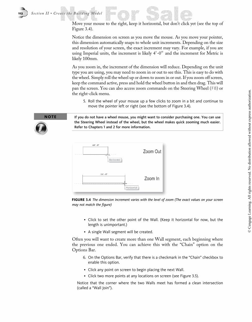
Move your mouse to the right, keep it horizontal, but don’t click yet (see the top ofFigure 3.4).
Notice the dimension on screen as you move the mouse. As you move your pointer,this dimension automatically snaps to whole unit increments. Depending on the sizeand resolution of your screen, the exact increment may vary. For example, if you areusing Imperial units, the increment is likely 4 0-0 00 and the increment for Metric islikely 100mm.
As you zoom in, the increment of the dimension will reduce. Depending on the unittype you are using, you may need to zoom in or out to see this. This is easy to do withthe wheel. Simply roll the wheel up or down to zoom in or out. If you zoom off screen,keep the command active, press and hold the wheel button in and then drag. This willpan the screen. You can also access zoom commands on the Steering Wheel (F8) orthe right-click menu.
5. Roll the wheel of your mouse up a few clicks to zoom in a bit and continue tomove the pointer left or right (see the bottom of Figure 3.4).
NOTE If you do not have a wheel mouse, you might want to consider purchasing one. You can usethe Steering Wheel instead of the wheel, but the wheel makes quick zooming much easier.Refer to Chapters 1 and 2 for more information.
• Click to set the other point of the Wall. (Keep it horizontal for now, but thelength is unimportant.)
• A single Wall segment will be created.
Often you will want to create more than one Wall segment, each beginning wherethe previous one ended. You can achieve this with the “Chain” option on theOptions Bar.
6. On the Options Bar, verify that there is a checkmark in the “Chain” checkbox toenable this option.
• Click any point on screen to begin placing the next Wall.
• Click two more points at any locations on screen (see Figure 3.5).
Notice that the corner where the two Walls meet has formed a clean intersection(called a “Wall Join”).
FIGURE 3.4 The dimension increment varies with the level of zoom (The exact values on your screenmay not match the figure)
112 S e c t i o n I I • Cr ea t e t h e Bu i l d i n g Mod e l
© C
enga
ge L
earn
ing.
All
right
s res
erve
d. N
o di
strib
utio
n al
low
ed w
ithou
t exp
ress
aut
horiz
atio
n.

7. Click the Start-End-Radius Arc icon on the Draw panel.
The Start-End-Radius Arc tool first places each of the endpoints and then adds theintermediate point last to define the degree of curvature. Other Arc options are alsoavailable.
• Move the pointer in any direction and click to place the end point of the Arc.
• Following the cue at the Status Bar, click to place the intermediate point of the Arc.
Continue to experiment by adding additional Wall segments as desired.
8. To finish adding Walls, click theModify tool on the Selection panel of the ribbon(or press the ESC key twice).
Think of these few Walls as a simple “warm up” exercise. Drawing them helped usexplore some of the basic Wall options. However, these Walls have been placed a bittoo randomly to be useful. Let’s delete them now and create some new ones.
Using a Crossing selection box
Before we can delete the existing Walls, we need to select them. There are many waysto select objects in Revit. Rather than learn them all at once, let’s take them one at atime as our current need dictates. A convenient way to select multiple objects at onetime is with the Window and Crossing selection methods. In either technique, youcreate a box by selecting two opposite corners with your mouse. To create a Windowselection, click and drag from left to right. Tomake a Crossing selection, click and dragthe opposite direction—from right to left. AWindow selection selects only those itemscompletely surrounded by the box, while a Crossing selects anything touched by orwithin the box. This was discussed in brief in Chapter 2. Let’s review it now.
9. Click a point below and to the right of the Walls you have on screen.
• Hold down the mouse button and drag up and to the left far enough to touch allobjects with the dashed (Crossing) selection box (see Figure 3.6).
FIGURE 3.5 Use the Chain option to create continuous Wall segments
FIGURE 3.6 Make a Crossing selection by dragging from right to left
Chap t e r 3 • Cr e a t i n g a Bu i l d i n g Lay ou t 113
© C
enga
ge L
earn
ing.
All
right
s res
erve
d. N
o di
strib
utio
n al
low
ed w
ithou
t exp
ress
aut
horiz
atio
n.

• When all of the Walls highlight, release the mouse button.
All of the Walls will turn blue to indicate that they are now selected. Once you have aselection of objects, you can manipulate their properties, move, rotate, or mirror them(notice that these and other tools appear on a Modify Walls tab of the ribbon) or youcan delete them.
10. Press the DELETE key on your keyboard to delete the Walls.
Adding Walls with the Rectangle Option
Several of the Wall shape icons that are available create Walls that form closed geo-metric shapes like rectangles, circles, and polygons. Often using these is the quickestway to lay out these more regular shapes. Let’s try the rectangle option now.
11. On the Home tab of the ribbon, click the Wall tool.
• Verify that Generic - 8 00 [Generic – 200mm] is chosen for the Element Type.
• Accept the defaults for Height and Location Line and then click the Rectangleshape icon on the Draw panel (see Figure 3.7).
Our project contains four elevation markers. Let’s zoom the screen to fit theseto the screen so they are visible.
12. On the keyboard, type ZF.
NOTE If you prefer, you can also choose Zoom To Fit from the Zoom tool on the Navigation Bar.However, where available, the keyboard shortcuts like the one suggested in the previousstep are usually quicker once you learn them. Shortcuts for zoom commands are listed inTable 1.4 in Chapter 1.
The mouse pointer will show a small rectangle next to it indicating that we are inrectangle drawing mode.
13. Click a point within the upper left region of the space surrounded by the eleva-tion markers.
• Move the mouse down and to the right and watch the values of the dimensions.
14. Click a point in the lower right region of the space surrounded by the elevationmarkers.
Notice that the temporary dimensions continue to display on the Walls justdrawn. Furthermore, these dimensions appear in blue. The blue color indicatesthat their values may be edited dynamically; or put another way, blue means“interactive.”
15. Click on the blue value of the horizontal dimension.
The value will become an editable text field.
FIGURE 3.7 Using the rectangle draw option for Walls
114 S e c t i o n I I • Cr ea t e t h e Bu i l d i n g Mod e l
© C
enga
ge L
earn
ing.
All
right
s res
erve
d. N
o di
strib
utio
n al
low
ed w
ithou
t exp
ress
aut
horiz
atio
n.

• Type a new value into this field and then press ENTER. (The exact value is unim-portant—see Figure 3.8).
NOTEThe value on your screen will vary from that shown in the figure.
16. The Wall command is still active. Using the same technique, draw another rect-angle overlapping the first.
Notice that the temporary dimensions now reference points on the first rectangle topoints on the new one. You can edit these values in the same way that we edited theones above. You can also move the witness lines of the dimensions to gain more con-trol over their exact locations. We will explore this technique below. If you wish, trysome of the other sketch shapes like circle or polygon. In the case of the polygon,additional controls will appear on the Options Bar to control the quantity of sides.
17. When you are finished exploring Walls, choose Close from the Applicationmenu to close the current project. When prompted to save, choose No.
Create an Existing Conditions LayoutNow that we have practiced adding a few Walls and seen some of the options avail-able while doing so, let’s begin creating an actual model. In this book we will followtwo projects from the early schematic phase through to the construction documentphase. We will start with the first floor existing conditions for our residential project.The residential project is an 800 SF [75 m2] residential addition. This project willrequire a little bit of demolition and new construction and will require plans, sections,elevations, details, and schedules. In this project we will explore the Phasing toolsin Revit—Demolition, Existing and New Construction will be articulated later inthe tutorial. This will give us the required separation between construction phasesof the project. The completed files for the residential project are available in theChapter03\Complete folder with the dataset files installed from the student compan-ion. You can open the completed version at any time to compare it to your progress.
Create a New Residential Project
We will use the same template file that we used above to begin our residential model.
1. Create a new project file using the default.rte [DefaultMetric.rte] template file aswe did in the “Create a New Project” heading above.
FIGURE 3.8 Use the temporary dimensions to edit the locations of the Walls
Chap t e r 3 • Cr e a t i n g a Bu i l d i n g Lay ou t 115
© C
enga
ge L
earn
ing.
All
right
s res
erve
d. N
o di
strib
utio
n al
low
ed w
ithou
t exp
ress
aut
horiz
atio
n.

Be sure that the Level 1 floor plan view is open onscreen. You can see this indi-cated in bold (under Views (all) > Floor Plans) on the Project Browser and in thetitle bar of the Revit Architecture window.
2. On the Home tab of the ribbon, click the Wall tool (shown in Figure 3.2 above).
• From the Type Selector, choose Generic - 12 00 [Generic – 300mm].
• For Height choose Unconnected and set the value to 18 00-0 0000 [5500].
TIP If you are using Imperial units, simply type 18 and then press ENTER. No unit symbol orzero inches is necessary. Also note that to enter a value like 18 0-2 1/2 00 you can type it inseveral ways. For example, you can type 18 0 2 1/2 00 or 18 0 2.5 00 or 18 2 1/2 or 18 2.5 or18.20833. Refer to the “Unit Conventions” topic in Chapter 2 for more information.
• For the Location Line, choose Finish Face: Exterior and then click the Rectanglesketch icon (see Figure 3.9).
3. Click two opposite corners on screen within the space bounded by the elevationmarkers (the exact size is not important for initial placement).
Notice that even though we have chosen a Location Line of Finish Face: Exterior, thetemporary dimensions still have witness lines at the centerlines of the Walls. This issimply a default behavior independent of theWall’s individual location line setting. Ifyou want to input a value for the dimension based upon the face of theWalls, you cansimply move the witness lines.
4. Click the small blue square handle on one of the horizontal dimension’s witnesslines. Zoom into the small blue square to see this better.
Notice that the witness line moves to one of the Wall faces. If you click it again,it will move again, this time to the opposite face. One more click returns it tothe centerline (see Figure 3.10).
FIGURE 3.9 Set the Options for the exterior Walls of the residential project
116 S e c t i o n I I • Cr ea t e t h e Bu i l d i n g Mod e l
© C
enga
ge L
earn
ing.
All
right
s res
erve
d. N
o di
strib
utio
n al
low
ed w
ithou
t exp
ress
aut
horiz
atio
n.

• Click the witness line handle (of the horizontal dimension) until both sides ref-erence the outside edges.
• Click the blue numeric value of the horizontal dimension, type: 33 00-0 0000 [10000]and then press ENTER.
5. Repeat this process on the vertical dimension making the outside face to facedimension equal to: 24 00-0 0000 [7300] (see Figure 3.11).
TIPIf your witness lines are in the wrong locations when you edit the temporary dimension,simply repeat the process to move the witness lines and then repeat the dimension editprocess.
CAUTIONBe careful not to click the small “permanent” dimension icon when editing the dimensionvalues. Clicking this icon will make the temporary dimension a “permanent dimension” (itwill remain in the current view even after the associated Wall is deselected). If this hap-pens, simply select the dimension and delete it.
FIGURE 3.10 Move the witness lines of the temporary dimension
FIGURE 3.11 Edit the size of the rectangle to match the desired outside dimensions
Chap t e r 3 • Cr e a t i n g a Bu i l d i n g Lay ou t 117
© C
enga
ge L
earn
ing.
All
right
s res
erve
d. N
o di
strib
utio
n al
low
ed w
ithou
t exp
ress
aut
horiz
atio
n.

6. On the Select panel, click the Modify tool, or press ESC twice to complete theoperation.
You should now have four walls in a rectangular configuration measuring 33 0-0 00 �24 0-0 00 [10000 � 7300] outside dimensions.
NOTE If you need to modify the dimensions after deselecting them, you can reselect any Wall andthe temporary dimensions will reappear. However, you will need to select one Wall at a timeto make edits. Select one Wall, edit witness lines if required, and then type in your desireddistance in the temporary dimension. Repeat in the other direction. Also, keep in mind thatthe element you select is the one that will move when editing the dimensions. On the QuickAccess Toolbar, click the Save icon.
• From the Application Button, select Save As…Project. In the Save As dialog, nav-igate to a location on your local system where you wish to save the project—your Documents folder, for example. (My Documents in Windows XP.)
• For the File name, type: 03 Residential and then click the Save button.
Offset Walls
Let’s begin adding the interior partitions. There are several techniques that we couldemploy to do this. In this sequence, we will use theOffset tool. TheOffset tool movesor copies the selected objects parallel to the originals by an amount that you input.This tool is located on the Modify tab of the ribbon.
7. On the Modify tab of the ribbon, click the Offset tool.
TIP The shortcut for offset is OF.
The Options Bar for Offset has two modes: Graphical and Numerical. When youchoose Graphical, the numeric input field is disabled and you use a temporary dimen-sion on screen to indicate the distance of the offset. When you choose the Numericaloption, you input the offset distance first, and then use the pointer on screen to indi-cate the side of the offset. In both cases, you can enable the “Copy” checkbox, whichwill create a copy of the object as it offsets. If you disable this option, the object youoffset will be moved parallel to itself by the amount you indicate.
• On the Options Bar, verify that Numerical is chosen (if it is not, choose it now).Zoom in closer if necessary. (Use your wheel mouse.)
• In the Offset field on the Options Bar, type 12 00-5 1/2 0000 [3794] and verify that“Copy” is selected.
The mouse pointer will change to an Offset cursor and the Status Bar will promptfor a selection.
• In the drawing window, move the Offset cursor over the upper edge of the bot-tom horizontal Wall.
A dashed line will appear indicating the location of the Offset. If you move yourmouse up and down this line will shift up and down as well (see Figure 3.12).
118 S e c t i o n I I • Cr ea t e t h e Bu i l d i n g Mod e l
© C
enga
ge L
earn
ing.
All
right
s res
erve
d. N
o di
strib
utio
n al
low
ed w
ithou
t exp
ress
aut
horiz
atio
n.

As in most places in Revit, if you press the TAB key, the pre-highlighted selection willcycle to the next available option. In this case, all fourWalls will pre-highlight and theoffset result would be a concentric ring inside or outside the building. Go ahead andtry it if you like. Press the TAB key once, and then move the pointer to indicate out-side or inside. The green dashed line will indicate a rectangle now instead of a singleedge. If you actually click to create theWalls, be sure to undo (Quick Access Toolbar)after this experimentation.
• When the dashed line appears above the Wall (inside the house) click themouse.
A new Wall will appear inside the house.
• Click the Modify tool, or press the ESC key twice to complete the operation.
Copying Walls
We can also copy Walls. You select the Wall to copy first and then click the Copytool.
8. Select the vertical Wall on the left.
A Modify Walls tab will appear on the ribbon.
• On the Modify panel, click the Copy tool.
TIPThe keyboard shortcut for Copy is CO.
New to Revit 2011, many editing tools in Revit allow you to first click the tool andthen select the element(s) that you wish to copy. In this case, you would click theCopy tool on the Modify tab first. Then following the prompt on the Status Bar,you select the Wall (or Walls) you wish to copy and press ENTER to complete theselection process. The rest of the command sequence would be the same.
With the Copy tool you input the distance of the offset on the screen. At the StatusBar, a prompt reads “Click to enter move start point.”
• Click a point anywhere on screen. (The exact start point is not important, but forconvenience, you can click directly on the Wall). Begin moving the Wall to theright, type 12 00-8 1/2 0000 [3818] and then press ENTER (see Figure 3.13).
FIGURE 3.12 Offsetting a new wall
Chap t e r 3 • Cr e a t i n g a Bu i l d i n g Lay ou t 119
© C
enga
ge L
earn
ing.
All
right
s res
erve
d. N
o di
strib
utio
n al
low
ed w
ithou
t exp
ress
aut
horiz
atio
n.
9. On the Select panel, click the Modify tool or press the ESC key twice.
10. Save your project.
Changing a Wall’s Parameters
One of the features that makes Revit such a powerful tool is the ability to easilychange an object’s parameters at any time, as design needs change. Let’s take a lookat modifying some of the walls as we continue with the layout of the first floor existingconditions for the residential project.
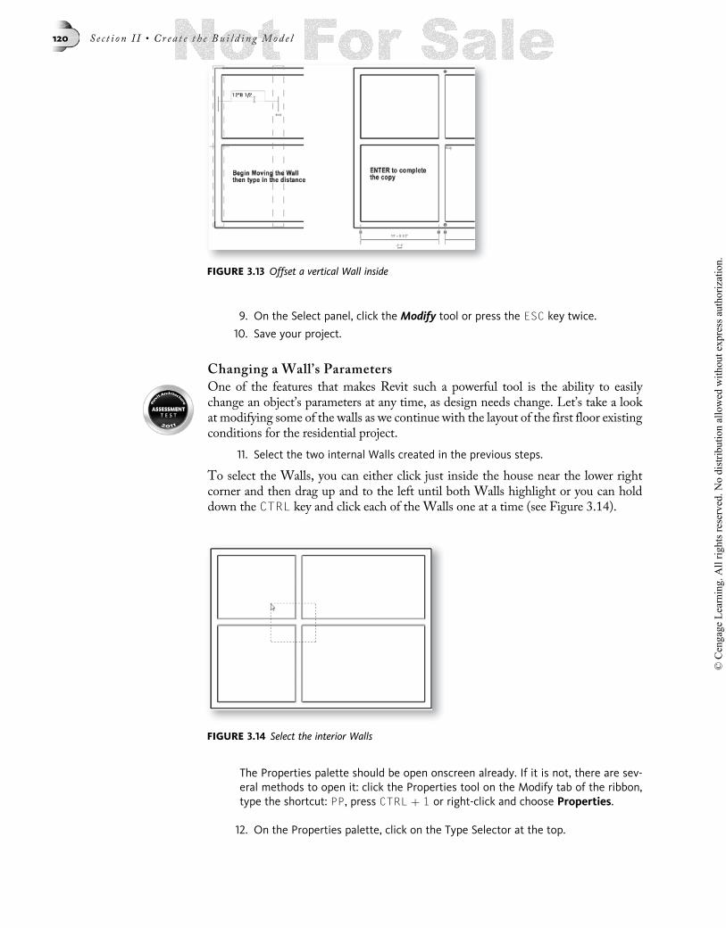
11. Select the two internal Walls created in the previous steps.
To select the Walls, you can either click just inside the house near the lower rightcorner and then drag up and to the left until both Walls highlight or you can holddown the CTRL key and click each of the Walls one at a time (see Figure 3.14).
The Properties palette should be open onscreen already. If it is not, there are sev-eral methods to open it: click the Properties tool on the Modify tab of the ribbon,type the shortcut: PP, press CTRL þ 1 or right-click and choose Properties.
12. On the Properties palette, click on the Type Selector at the top.
FIGURE 3.14 Select the interior Walls
FIGURE 3.13 Offset a vertical Wall inside
120 S e c t i o n I I • Cr ea t e t h e Bu i l d i n g Mod e l
© C
enga
ge L
earn
ing.
All
right
s res
erve
d. N
o di
strib
utio
n al
low
ed w
ithou
t exp
ress
aut
horiz
atio
n.

• Choose Generic – 5 0000 [Interior - 135mm Partition (2-hr)] from the Type list.
• Beneath the Constraints grouping, choose Wall Centerline for the LocationLine (see Figure 3.15).
TIPTo make this change, click in the Location Line field, and then click the small down arrowthat appears to choose the Wall Centerline option from the popup menu.
To apply such a change, you either click the Apply button on the Properties palette,or simply shift focus away from the palette by moving your mouse away from the pal-ette. This will apply the change automatically.
13. Shift focus away from the Properties palette or click Apply to accept thechanges.
• Notice the change to the Walls.
Let’s verify that everything is in the correct place. As noted above, we are laying outthe existing conditions of our residential project. Therefore, the locations of theWallsthat we just placed are based on field dimensions. The room in the lower left corner ofthe plan is supposed to be 11 0-6[3500] � 11 0-9[3658]. We can verify these dimen-sions and easily make adjustments as necessary.
Adjust Wall Locations
In the “Create a New Residential Project” heading above, we learned to use the tem-porary dimensions and the handles on the witness lines to edit the location of Walls.We can use the same technique to verify our dimensions now.
14. Click on the interior horizontal Wall.
The temporary dimensions will appear indicating its current location relative to theotherWalls. However, depending on the settings of your system, the dimensions maybe from the centerlines. The desired size of the room that we are verifying are to theinside faces of the Walls (as you might expect from field dimensions). Therefore, wecould use the witness line technique covered above or we can change the default be-havior of the dimensions from now on. We do this with the Temporary Dimensionscommand.
FIGURE 3.15 Change the parameters of the interior Walls on the Properties palette
Chap t e r 3 • Cr e a t i n g a Bu i l d i n g Lay ou t 121
© C
enga
ge L
earn
ing.
All
right
s res
erve
d. N
o di
strib
utio
n al
low
ed w
ithou
t exp
ress
aut
horiz
atio
n.

NOTE Revit will now remember the modified location of witness lines during your work session. Totry it out, select a Wall and edit the witness line of a temporary dimension as indicatedabove in the “Create a New Residential Project” topic. Deselect the Wall. Reselect thesame Wall and notice that the witness lines remember the modified location. When youclose the project and reopen, they will reset to their defaults.
15. On the Manage tab of the ribbon, on the Settings panel, click the Additional Set-tings drop-down button and choose Temporary Dimensions.
• In the Walls area, click Faces and then click OK (see Figure 3.16).
16. Click the horizontal interior Wall again.
The dimension from the inside face of the bottom horizontal exterior Wall to theinside face of the selected Wall should be 11 0-5 1/2 00 [3658].
17. Click on the vertical interior Wall.
This time, the dimension from the inside face of the left exterior Wall to the insideface of the selected Wall should read 11 0-8 1/2 00 [3650]. However, this value is notcorrect; the distance should be 11 0-6 00 [3500]. Despite best efforts to transfer fieldmeasurements to our building model, an error crept into our calculations. Fortu-nately, errors like this are very easy to correct in Revit.
• Click the blue text of the left-hand dimension and type the correct value 11 00-6 0000
[3500] (see Figure 3.17).
FIGURE 3.16 Change the Temporary Dimensions to measure from Wall faces
FIGURE 3.17 Edit the Temporary Dimension to move the Wall to the correct location
122 S e c t i o n I I • Cr ea t e t h e Bu i l d i n g Mod e l
© C
enga
ge L
earn
ing.
All
right
s res
erve
d. N
o di
strib
utio
n al
low
ed w
ithou
t exp
ress
aut
horiz
atio
n.

18. Save the project.
TIPIf you find the text size of the Temporary Dimensions difficult to read, open the Applicationmenu and choose Options. On the Graphics tab, in the “Temporary Dimension Text Appear-ance” area, choose a larger size value and then click OK.
Sketching Walls
The offset and copy techniques covered above are effective ways to add new Wallsbased upon Walls already existing in the model. In many cases, however, it is easierto sketch the new Walls and then use the temporary dimensions to position themcorrectly. Let’s try that technique next.
19. On the Home tab of the ribbon, click the Wall tool.
• From the Type Selector (on the Properties palette), choose Generic – 5 0000
[Interior - 135mm Partition (2-hr)].
• For the Sketch Shape, choose Line.
• For Location Line, choose Wall Centerline.
20. Move the mouse over the exterior vertical Wall on the left.
Notice the temporary dimension that appears.
• When the value of the dimension above the interior horizontal Wall is about4 00-0 0000 [1200] click to set the first point.
• Move the pointer horizontally to the right and click to set the second point justpast the middle of the plan (see Figure 3.18).
NOTEThe exact locations of both clicks are not critical since we will use temporary dimensions toedit them next. Use the figure to achieve approximate placement.
• Click the Modify tool or press ESC twice to complete the command and thenclick to select the Wall just created.
Several temporary dimensions will remain on screen after the placement ofthe Wall.
21. Click the blue text of the vertical temporary dimension between the new Wallthat you just created and the other horizontal interior Wall (the 4 00-0 0000 [1200]space from above).
• Type 3 00-10 0000 [1170] and then press ENTER (see the left side of Figure 3.19).
FIGURE 3.18 Sketch a Wall segment above the horizontal interior Wall
Chap t e r 3 • Cr e a t i n g a Bu i l d i n g Lay ou t 123
© C
enga
ge L
earn
ing.
All
right
s res
erve
d. N
o di
strib
utio
n al
low
ed w
ithou
t exp
ress
aut
horiz
atio
n.

NOTE This is a face to face dimension. Once you edited the Temporary Dimension setting above, itshould remain persistent.
22. Using the same process, create a vertical Wall approximately 3 00-0 0000 [900] to theleft of the existing interior vertical Wall.
• Start at the lower exterior Wall and draw up until it intersects with the upperhorizontal interior Wall (the one drawn in the last step).
• Using the temporary dimensions, edit the face to face distance between thetwo Walls to be 2 00-6 0000 [750] (see the right side of Figure 3.19).
• Click the Modify tool or press the ESC key twice to complete the edit.
23. Select the vertical interior Wall that you just completed (the one on the left).
At each end of the Wall is a small round blue handle.
• Click and drag the handle at the bottom upward.
• Using the temporary guidelines that appear, drag up and snap to the horizontalWall (see Figure 3.20).
FIGURE 3.19 Sketch Walls and use temporary dimensions to fine-tune their placement
FIGURE 3.20 Drag the Wall End Handle up to the intersection with the horizontal Wall
124 S e c t i o n I I • Cr ea t e t h e Bu i l d i n g Mod e l
© C
enga
ge L
earn
ing.
All
right
s res
erve
d. N
o di
strib
utio
n al
low
ed w
ithou
t exp
ress
aut
horiz
atio
n.

Trim Walls
While the control handles are quick and easy, another common way to edit a planlayout is using the Trim and Extend tools.
24. On the Modify tab of the ribbon, click the Trim tool.
TIPThe keyboard shortcut for Trim is TR.
The Trim tool will create a clean corner from the two segments by either lengtheningor shortening the selected segments. Click the vertical Wall that was just edited withthe handle.
NOTEPay attention to the prompt at the Status Bar, in this case instructing you to select the firstWall that you want to Trim or Extend. Please note that you are further prompted to selectthe portion that you wish to keep.
25. Next click the horizontal Wall to the right of the intersection (see Figure 3.21).
26. Click the Modify tool or press the ESC key twice.
Adding Walls Using the Pick Lines Mode
Let’s continue adding to our wall layout by using a technique that combines featuresof both the previous techniques. We will add Walls using theWall tool and its “PickLines” mode. We will use this in conjunction with the Offset option on the OptionsBar to place the Wall close to where we need it.
27. On the Home tab of the ribbon, click the Wall tool.
• On the Type Selector, verify that the Type is set to: Generic – 5 0000 [Interior -135mm Partition (2-hr)].
• On the Draw panel, click the Pick Lines icon to activate this mode.
• Verify that the Location Line is Wall Centerline.
• On the Options Bar, in the Offset field, type 6 00-0 0000 [1800].
FIGURE 3.21 Using Trim to create the closet corner
Chap t e r 3 • Cr e a t i n g a Bu i l d i n g Lay ou t 125
© C
enga
ge L
earn
ing.
All
right
s res
erve
d. N
o di
strib
utio
n al
low
ed w
ithou
t exp
ress
aut
horiz
atio
n.

28. Move the mouse next to the right side of the interior vertical Wall in the middleof the plan.
The right face of the Wall will pre-highlight.
Click the wall to place the new wall.
• Be sure that the temporary guideline indicates a new Wall to the right and thenclick.
• Click the Modify tool or press the ESC key twice.
29. Select the new Wall and edit the dimension between this Wall and the one fromwhich it was offset to 6 0-6 00 [1983] (see Figure 3.22).
In this case we used two steps: first offsetting to an approximate amount and thenusing the temporary dimensions to fine-tune the result. If you want to calculate theexact offset to use instead of editing the temporary dimension, you can do so. TheOffset value will be measured from the line you pick to the Location Line of thenew Wall—in this case Wall Centerline. Therefore, half of the Wall’s width wouldhave to be added to the dimension. Despite the relative ease of this calculation, it istypically easier to place the Wall close and then edit the dimension to the exact valueas we have done here. The choice is yours.
Trim/Extend Single Element Mode
Let’s modify a few more Wall segments using the Trim/Extend Single Element tool.
30. On the Modify tab of the ribbon, click the Trim/Extend Single Element tool.
C
FIGURE 3.22 Adding a Wall using the Pick Lines mode
126 S e c t i o n I I • Cr ea t e t h e Bu i l d i n g Mod e l
© C
enga
ge L
earn
ing.
All
right
s res
erve
d. N
o di
strib
utio
n al
low
ed w
ithou
t exp
ress
aut
horiz
atio
n.

In this mode you first select the element to use as a boundary and then the click theWall or line you wish to extend or trim to this boundary.
TIPRemember to read the prompts on the Status Bar.
• Click the vertical interior Wall on the right as the boundary (the one we justcreated).
• Click the short horizontal Wall at the top of the closet to extend (see Figure 3.23).
31. Use the same technique to trim away the vertical Wall at the top of the closet(Remember to click the piece you want to keep—read the Status Bar.)
• Click the Modify tool or press the esc key twice.
Using the Split and Move Tools
The layout is coming along. Next let’s focus on the stair hallway in the middle ofthe plan.
32. On the Modify tab, click the Split Element tool.
TIPThe keyboard shortcut for Split is SL.
• Place the cursor (now shaped like a knife) over the long horizontal Wall in themiddle of the plan where it intersects the left vertical Wall in the middle.
The horizontal Wall should highlight. If it does not, press the TAB key a fewtimes until it does.
• When the horizontal Wall is highlighted and small vertical line appears at thecursor, click the mouse (see the left side and middle of Figure 3.24).
FIGURE 3.23 Use the Trim/Extend Single Element to create “T” Intersections
Chap t e r 3 • Cr e a t i n g a Bu i l d i n g Lay ou t 127
© C
enga
ge L
earn
ing.
All
right
s res
erve
d. N
o di
strib
utio
n al
low
ed w
ithou
t exp
ress
aut
horiz
atio
n.
• Click the Modify tool or press the ESC key twice.
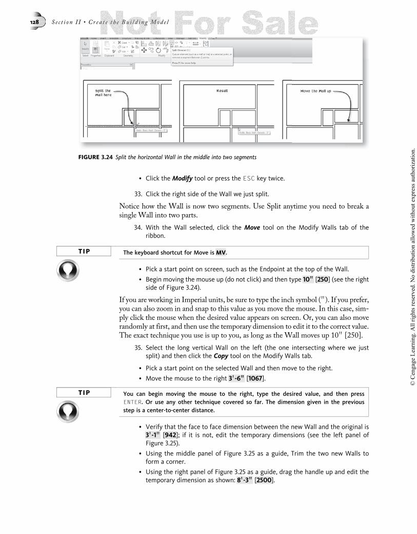
33. Click the right side of the Wall we just split.
Notice how the Wall is now two segments. Use Split anytime you need to break asingle Wall into two parts.
34. With the Wall selected, click the Move tool on the Modify Walls tab of theribbon.
TIP The keyboard shortcut for Move is MV.
• Pick a start point on screen, such as the Endpoint at the top of the Wall.
• Begin moving the mouse up (do not click) and then type 10 0000 [250] (see the rightside of Figure 3.24).
If you are working in Imperial units, be sure to type the inch symbol ( 00). If you prefer,you can also zoom in and snap to this value as you move the mouse. In this case, sim-ply click the mouse when the desired value appears on screen. Or, you can also moverandomly at first, and then use the temporary dimension to edit it to the correct value.The exact technique you use is up to you, as long as the Wall moves up 10 00 [250].
35. Select the long vertical Wall on the left (the one intersecting where we justsplit) and then click the Copy tool on the Modify Walls tab.
• Pick a start point on the selected Wall and then move to the right.
• Move the mouse to the right 3 00-6 0000 [1067].
TIP You can begin moving the mouse to the right, type the desired value, and then pressENTER. Or use any other technique covered so far. The dimension given in the previousstep is a center-to-center distance.
• Verify that the face to face dimension between the new Wall and the original is3 00-1 0000 [942]; if it is not, edit the temporary dimensions (see the left panel ofFigure 3.25).
• Using the middle panel of Figure 3.25 as a guide, Trim the two new Walls toform a corner.
• Using the right panel of Figure 3.25 as a guide, drag the handle up and edit thetemporary dimension as shown: 8 00-3 0000 [2500].
FIGURE 3.24 Split the horizontal Wall in the middle into two segments
128 S e c t i o n I I • Cr ea t e t h e Bu i l d i n g Mod e l
© C
enga
ge L
earn
ing.
All
right
s res
erve
d. N
o di
strib
utio
n al
low
ed w
ithou
t exp
ress
aut
horiz
atio
n.

36. Save your Project.
Sketch the Remaining Walls
At the top middle of the plan is a small half-bath. Let’s sketch these Walls to com-plete the Wall layout of our first floor existing conditions.
37. On the Home tab of the ribbon, click the Wall tool.
The defaults should remain from the previous Walls. Verify that the Wall Type isGeneric – 5 0000 [Interior - 135mm Partition (2-hr)], the Draw shape is Line andthe Location Line is: Wall Centerline.
• Working at the top middle of the plan, sketch two Wall segments to create asmall half-bath.
• Edit the temporary dimensions to make the inside clear dimensions of the half-bath 4 00-4 0000 [1300] � 3 00-6 0000 [1050] (see Figure 3.26).
HINTRemember: Select the Wall that you want to move before editing a temporary dimension.The highlighted wall will move relative to the non-selected Wall.
FIGURE 3.25 Copy, Trim and Edit Walls for the hallway stairs
FIGURE 3.26 Sketch the small half-bath and edit the dimensions to the desired values
Chap t e r 3 • Cr e a t i n g a Bu i l d i n g Lay ou t 129
© C
enga
ge L
earn
ing.
All
right
s res
erve
d. N
o di
strib
utio
n al
low
ed w
ithou
t exp
ress
aut
horiz
atio
n.

38. Extend the vertical Wall in the middle of the stair hallway up to the half-bath.
• Use the Split tool with the “Delete Inner Segment” option on the Options Bar toremove the small piece of Wall shown in the middle panel of Figure 3.27.
• Use the Trim tool to complete the layout as shown in the right panel of Figure 3.27.
Figure 3.28 shows the completed Wall layout for the residential project’s first floorexisting conditions. There is still plenty of work to do, but use the illustration to checkyour work before you continue.
39. Save the Project.
WORKING WITH PHASINGWe have completed the layout of existing walls on the first floor of the house. Assign-ing the Walls to a particular construction phase will help us distinguish them as ex-isting construction as the project progresses. Revit includes robust Phasing toolsallowing us to quickly and easily designate theseWalls as existing construction. Everyelement in the model has two phasing parameters: “Phase Created” and “Phase
FIGURE 3.27 Complete the Wall Layout using Trim/Extend and Split
FIGURE 3.28 Your completed Wall Layout should look like this
130 S e c t i o n I I • Cr ea t e t h e Bu i l d i n g Mod e l
© C
enga
ge L
earn
ing.
All
right
s res
erve
d. N
o di
strib
utio
n al
low
ed w
ithou
t exp
ress
aut
horiz
atio
n.

Demolished.” In this way you can track the “life span” of any element in the model. Inthe case of the Walls that we have drawn here, all of them are existing constructionand none will be demolished yet. We will be demolishing some of the Windows andDoors later on in the chapter.
Assign Walls to a Construction Phase
1. Using a window selection (click and drag to surround all Walls), select all of theWalls in the model (but not the elevation markers).
The Properties palette should still be open. If it is not, press CTRL þ 1 to openit now.
• On the Properties palette, scroll down and locate the Phasing grouping.
• For “Phase Created,” choose Existing.
• For the “Phase Demolished,” verify that None is chosen and then click the Applybutton (see Figure 3.29).
2. Deselect all of the Walls to see the change.
• You can deselect the Walls by simply clicking in the white space next to theWalls. You can also click the Modify tool or press the ESC key twice.
The Walls will display in a lighter lineweight and will also be colored gray. This in-dicates that they are existing construction. Assigning a phase to an element automat-ically assigns a graphic override to it. You can control the settings of these overrides aswell as edit and add phases in the Phasing dialog. To open this dialog, click theMan-age tab and on the Phasing panel, click the Phases button. Feel free to explore thisdialog now if you wish. A good example of a typical task that you could perform inthis dialog would be to set up phases of construction in a large project. For example,you could create a “Foundations and Caissons” phase, “Phase 1” and “Phase 2 NewConstruction” phases. For our residential project, the out-of-the-box phases of “Ex-isting” and “New Construction” are sufficient. Therefore, if you make any changes inthe Phases dialog, please do not apply them at this time, or undo them after you arefinished exploring.
3. Save the project.
FIGURE 3.29 Assign the Existing Phase to the selected Walls
Chap t e r 3 • Cr e a t i n g a Bu i l d i n g Lay ou t 131
© C
enga
ge L
earn
ing.
All
right
s res
erve
d. N
o di
strib
utio
n al
low
ed w
ithou
t exp
ress
aut
horiz
atio
n.

Exploring the View Properties
At this time, it is appropriate to explore Phasing a bit deeper to get a full understand-ing of the tools available. Many of the changes we are about to make are not requiredby our residential project, therefore we will save a copy of the project in which to ex-periment and then reopen the original when we finish exploring.
Make sure you have saved the project.
1. From the Application menu, choose Save As . Project.
• Name the project 03 Residential – Temp.rvt and then click Save. On the Hometab, click the Wall tool.
• Accept all the default settings and draw a single Wall segment anywhere in themodel, but joining or crossing one or more of the existing Walls.
• Click the Modify tool or press the ESC key twice.
Notice that the new Wall came in as New Construction. Notice also that it did joinwith the existing Wall. Elements you create automatically use the current phase as-signed to the view. In this case, while we changed the phase of the Walls to Existing,the Level 1 floor plan view is still assigned to New Construction. Therefore all newlydrawn elements will default to New Construction as well.
2. Select any Existing (phase) Wall.
• On the Properties palette locate the Phase Demolished list, choose New Con-struction and then click Apply.
• Deselect the Wall.
Notice that the Wall is now displayed using a dashed line style.
3. Select a different Existing (phase) Wall.
• From the Phase Demolished list, choose Existing and then click Apply.
Notice that this time, the Wall has disappeared. This is because each view (Level 1floor plan in this case) has their own phasing parameters that control display: “Phase”and “Phase Filter.” To understand why theWall disappeared, let’s change the currentphase of the Level 1 floor plan view to Existing and see how the display of elementschanges.
4. Make sure that there are no elements selected and look carefully at the Proper-ties palette.
Notice that the palette still has many active parameters. Look carefully at the top ofthe palette; the Type Selector is grayed out, but just beneath it the drop-down listreads: Floor Plan: Level 1. This tells us that instead of seeing the properties of a se-lected element, the palette is now displaying the properties of the view itself: “Level1”. Regardless, to Revit both items have properties we can manipulate. (For more in-formation on this concept, you can review the “Properties Palette and the Type Selec-tor” topic and Figure 2.18 in Chapter 2). As you can see, like our Walls above, viewsalso have two phasing parameters in a “Phasing” grouping at the bottom of thepalette.
• Beneath the Phasing grouping, for “Phase,” choose Existing.
• Click Apply to see the change (see Figure 3.30).
132 S e c t i o n I I • Cr ea t e t h e Bu i l d i n g Mod e l
© C
enga
ge L
earn
ing.
All
right
s res
erve
d. N
o di
strib
utio
n al
low
ed w
ithou
t exp
ress
aut
horiz
atio
n.

This change makes the “Existing” phase the current phase for the Level 1 view.Therefore, the view will now show only items that existed in that phase. This meansthat no elements assigned to the New Construction phase will show (because they donot yet exist during the Existing phase time period). The Wall that we specified asdemolished in New Construction will now appear solid again because during the Ex-isting phase, it was not yet demolished. Furthermore, all of the previously light grayWalls now appear bold and black. That is because relative to the current phase (Ex-isting), they are (were) new. Phasing essentially gives us a timeline with which to viewour projects.When you set a view to a different phase, the relative “definition” of “Ex-isting,” “New” and “Demolished” shift accordingly. Finally, the Wall that we set to“demolished” in the Existing Phase now appears again, but it is dashed and crosshatched. This style indicates “temporary” construction, which occurs when an ele-ment is both created and demolished within the same phase. Examples of temporaryelements are temporary dust walls, construction barrier, or possibly furniture that isrelocated to a temporary space.
While we can create as many phases as we need for a particular project, Revit gives usfour conditions (Phase Status) that can be used to describe (and graphically convey)an element at any point in time. These are built into the software. You can edit theirdisplay characteristics but you cannot add or delete them. The four states are “Exist-ing,” “New,” “Demolished” and “Temporary.”
5. Draw another Wall.
• Select the new Wall and study its phasing Properties.
Notice that the newly drawn Wall was automatically assigned to the Existing phase.Any elements that we draw will automatically be added to the current phase of theview. We will make use of this technique below when we add Doors and Windows.
In addition to the current Phase setting, we can also assign a “Phase Filter” in theView Properties dialog. A Phase Filter does not change the active phase; rather itchanges which elements display and how they appear in the current view based ontheir phase “lifespan” designations. By default, all views are set to “Show All.” SeveralPhase Filters are included in the default templates from which our project was created.To see some of these, be sure to deselect all elements or select Floor Plan: Level 1from the selection list at the top of the Properties palette. Scroll down and you willsee the Phase Filter drop-down for the current view. For example, if you chooseNone, all elements will display (from all phases) and their graphics will display the
FIGURE 3.30 Change the current phase of a view and study the results on the elements shown
Chap t e r 3 • Cr e a t i n g a Bu i l d i n g Lay ou t 133
© C
enga
ge L
earn
ing.
All
right
s res
erve
d. N
o di
strib
utio
n al
low
ed w
ithou
t exp
ress
aut
horiz
atio
n.

same regardless of phase setting. This is probably not the most useful of Phase Filters.There are several other possibilities available; some might be easier to grasp withmore than phases in the project than the two default ones. Keep in mind as youexplore further, that the Phase Filter and Phase setting work together. For example,if you choose Show Complete for the Phase Filter and leave the Phase of the view setto Existing, you will see different results than if you set the Phase back to New Con-struction. Give it a try. Show Complete displays how the project will look at the com-pletion of the current phase. This means that all elements will appear bold and nodemolition will be displayed. Another example is “Show Previous Phase.” This willmake everything disappear if the current phase is Existing since there is currently nophase before Existing in the current project, however, everything but any newlydrawn Walls would display if you change the Phase to New Construction. LikePhases, Phase Filters can be edited in the Phasing dialog.
When you are finished experimenting with Phasing, return to the previously savedresidential project file.
6. From the Application menu, choose Close.
• It is not necessary to save 03 Residential-Temp.
7. From the Application menu, choose 03 Residential from the Recent Documentslist to re-open it.
It may be possible to click the undo icon several times to restore the drawing to thestate before we began demolishing and adding extraneous Walls. It is likely easier tosimply reopen the saved version. Regardless, theWall layout should look like it did inFigure 3.29 with all Walls assigned to the Existing phase before continuing.
If you prefer, a version of the project file in the correct state is provided for your con-venience in the Chapter03 folder. The file is named: 03 Residential-Walls.rvt [03Residential-Walls-Metric.rvt].
WORKING WITH DOORS AND WINDOWSContinuing with our layout of the residential existing conditions, let’s add someDoors and Windows. Doors and Windows automatically interact with Walls wheninserted to create the opening and attach themselves to theWall in an intelligent way.Doors and Windows cannot be placed free-standing in a Revit model. They must beinserted in an appropriate host Wall.
Add a Door
Doors are “Wall-hosted” elements. This means that Doors must be placed withinWalls. Like Walls, Doors have both type and instance parameters. A Door Familywith several types has been included in the out-of-the-box template file from whichour residential project was based.
1. Be sure that the Level 1 view of the Residential project is open and then zoomout to see the entire plan layout.
You can do this with the mouse wheel or the commands on the Navigation Bar.
2. On the Home tab, click the Door tool (see Figure 3.31).
TIP The keyboard shortcut for Door is DR.
134 S e c t i o n I I • Cr ea t e t h e Bu i l d i n g Mod e l
© C
enga
ge L
earn
ing.
All
right
s res
erve
d. N
o di
strib
utio
n al
low
ed w
ithou
t exp
ress
aut
horiz
atio
n.

Much like the Wall tool, when you click the Door tool, a context tab is appended tothe Modify tab, some options appear on the Options Bar and the Properties palettealso shows relevant settings. The Status Bar prompt will read: “Click on a Wall toplace Door.” This project has one Door Family currently loaded named Single Flush[M_Single-Flush]. This Family has several types.
• From the Type Selector (on the Properties palette), choose 36 00 3 80 00 [0915 32032mm].
The following list explains the major fields and controls shown on the ribbon,Options Bar and Properties palette when you are adding a Door (see Figure 3.32).
• Load Family—Use this button to access the external libraries and load DoorFamilies and their types not already available in the current project. “Libraries”are folders containing Family files on your hard drive or network server.
FIGURE 3.31 The Door tool on the Home tab
FIGURE 3.32 Choose your options for adding Doors on the ribbon, the Options Bar and the Proper-ties palette
Chap t e r 3 • Cr e a t i n g a Bu i l d i n g Lay ou t 135
© C
enga
ge L
earn
ing.
All
right
s res
erve
d. N
o di
strib
utio
n al
low
ed w
ithou
t exp
ress
aut
horiz
atio
n.
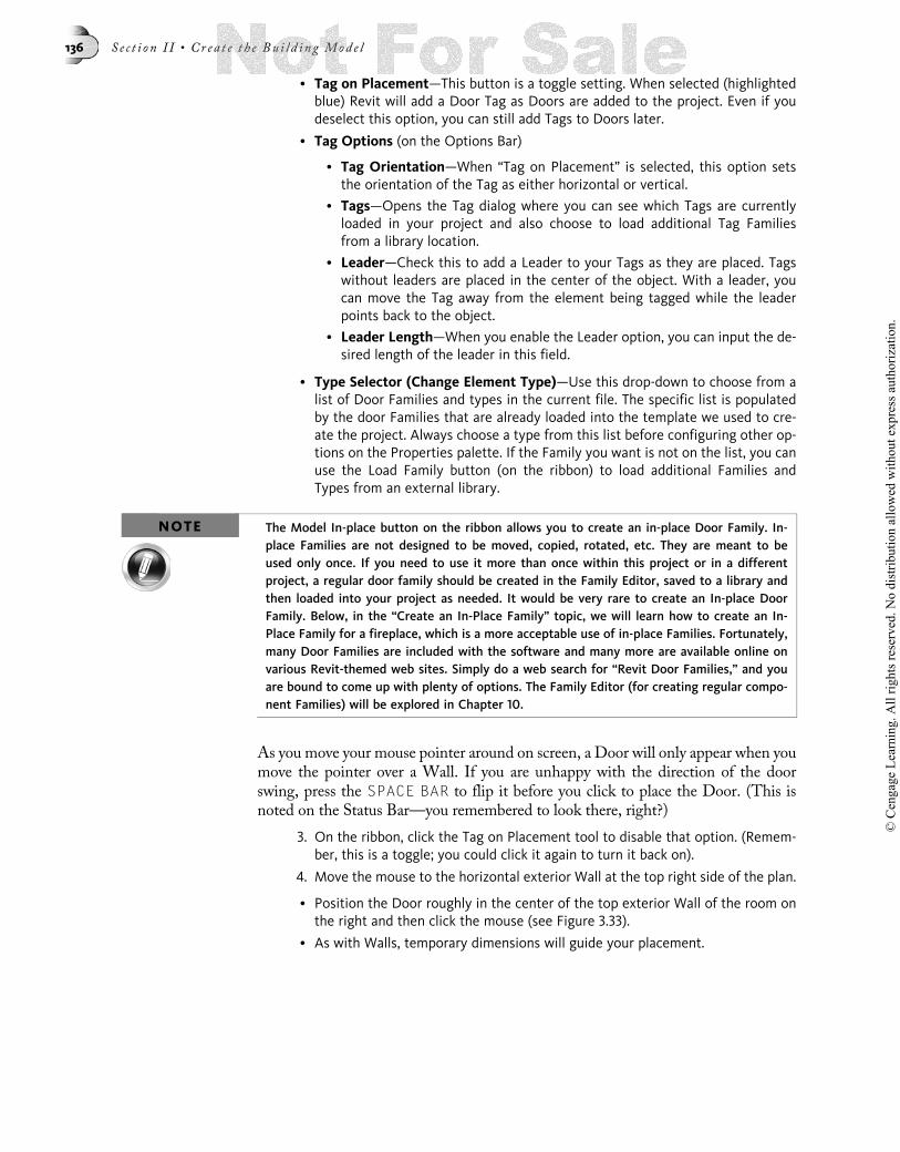
• Tag on Placement—This button is a toggle setting. When selected (highlightedblue) Revit will add a Door Tag as Doors are added to the project. Even if youdeselect this option, you can still add Tags to Doors later.
• Tag Options (on the Options Bar)
• Tag Orientation—When “Tag on Placement” is selected, this option setsthe orientation of the Tag as either horizontal or vertical.
• Tags—Opens the Tag dialog where you can see which Tags are currentlyloaded in your project and also choose to load additional Tag Familiesfrom a library location.
• Leader—Check this to add a Leader to your Tags as they are placed. Tagswithout leaders are placed in the center of the object. With a leader, youcan move the Tag away from the element being tagged while the leaderpoints back to the object.
• Leader Length—When you enable the Leader option, you can input the de-sired length of the leader in this field.
• Type Selector (Change Element Type)—Use this drop-down to choose from alist of Door Families and types in the current file. The specific list is populatedby the door Families that are already loaded into the template we used to cre-ate the project. Always choose a type from this list before configuring other op-tions on the Properties palette. If the Family you want is not on the list, you canuse the Load Family button (on the ribbon) to load additional Families andTypes from an external library.
NOTE The Model In-place button on the ribbon allows you to create an in-place Door Family. In-place Families are not designed to be moved, copied, rotated, etc. They are meant to beused only once. If you need to use it more than once within this project or in a differentproject, a regular door family should be created in the Family Editor, saved to a library andthen loaded into your project as needed. It would be very rare to create an In-place DoorFamily. Below, in the “Create an In-Place Family” topic, we will learn how to create an In-Place Family for a fireplace, which is a more acceptable use of in-place Families. Fortunately,many Door Families are included with the software and many more are available online onvarious Revit-themed web sites. Simply do a web search for “Revit Door Families,” and youare bound to come up with plenty of options. The Family Editor (for creating regular compo-nent Families) will be explored in Chapter 10.
As you move your mouse pointer around on screen, a Door will only appear when youmove the pointer over a Wall. If you are unhappy with the direction of the doorswing, press the SPACE BAR to flip it before you click to place the Door. (This isnoted on the Status Bar—you remembered to look there, right?)
3. On the ribbon, click the Tag on Placement tool to disable that option. (Remem-ber, this is a toggle; you could click it again to turn it back on).
4. Move the mouse to the horizontal exterior Wall at the top right side of the plan.
• Position the Door roughly in the center of the top exterior Wall of the room onthe right and then click the mouse (see Figure 3.33).
• As with Walls, temporary dimensions will guide your placement.
136 S e c t i o n I I • Cr ea t e t h e Bu i l d i n g Mod e l
© C
enga
ge L
earn
ing.
All
right
s res
erve
d. N
o di
strib
utio
n al
low
ed w
ithou
t exp
ress
aut
horiz
atio
n.

Notice that the Door appears in the drawing and cuts a hole in the Wall. However,notice that the hole in the Wall is filled with dashed lines. This is Phasing at workagain. At the start of this segment, we returned to the saved copy of the file, whichhad the Level 1 floor plan view’s phase set to “New Construction.” Therefore, RevitArchitecture is showing this Door as being a new Door placed into an existing Wall.This requires the opening for the Door to be shown as demolition while the Doorappears as new construction.
5. Click the Modify tool or press the ESC key twice.
Change the Phase Filter
Let’s try repeating the Phase Filter exercise above to see the different ways that thiscondition will display in each phase.
6. Make sure that there are no elements selected; on the Properties palette, makesure that Floor Plan: Level 1 is listed at the top.
• Beneath the Phasing grouping, for “Phase Filter,” choose Show Previous 1Demo.
• Click Apply to see the change (see the top of Figure 3.34).
With this phase filter active, you only see the previous phase (Existing in this casesince it is the phase that occurs before New Construction) and any demolition. Inthis case, the only demolition is the opening for the Door.
7. Edit the view Properties again.
• Beneath the Phasing grouping, for “Phase Filter,” choose Show Complete.
• Click Apply to see the change (see the bottom of Figure 3.34).
This filter shows what the view would look like when the final phase is complete. Soin this case, all the Walls appear bold and there is no demolition shown.
FIGURE 3.33 Click to place the first Door
Chap t e r 3 • Cr e a t i n g a Bu i l d i n g Lay ou t 137
© C
enga
ge L
earn
ing.
All
right
s res
erve
d. N
o di
strib
utio
n al
low
ed w
ithou
t exp
ress
aut
horiz
atio
n.

8. On the Properties palette, choose Show All for the Phase Filter.
The power and potential of the Phasing parameters was seen when we explored theseoptions with just Walls. Now that we have added a Door, we can truly see the fullpotential of these tools. If this Door truly were a new Door being added to these ex-isting Walls, all of these graphical behaviors would be managed for us automaticallyby Revit simply by assigning the Door to the New Construction Phase parameter aswe have done here. It turns out that this Door is actually an existing Door. Therefore,we need to change its Phase parameter to make it (and the Wall) display properly.
9. Select the Door in the model.
Notice that the Properties palette now displays the properties of the Door.
• Beneath the Phasing grouping, for “Phase Created,” choose Existing.
• Click Apply to accept the change to this instance of the door and then deselectthe Door by clicking in the white background of the Canvas area.
The Door now displays the same as the Wall in which it is inserted and the dasheddemolition lines no longer display. This is because the Door andWall now belong tothe same Phase, therefore there is no demolition required. Since we are going to addseveral more existing Doors, let’s change the view’s active Phase to Existing (as wedid above) to save us the trouble of having to edit phase property of the Doors (andWindows that we will add below) later on.
10. On the Properties palette, be sure that the properties of the floor plan view aredisplayed and then choose Existing for the Phase.
The Walls will turn bolder to reflect this change.
FIGURE 3.34 Change the Phase Filter to view the model at different points in time relative to thecurrent Phase
138 S e c t i o n I I • Cr ea t e t h e Bu i l d i n g Mod e l
© C
enga
ge L
earn
ing.
All
right
s res
erve
d. N
o di
strib
utio
n al
low
ed w
ithou
t exp
ress
aut
horiz
atio
n.
NOTEA typical set of construction documents requires existing conditions, demolition and newconstruction drawings. In Revit Architecture this is easily achieved by duplicating the views(plans, sections and/or elevations, even schedules) and editing the views’ Phase and PhaseFilter parameters to display the correct data. Refer to the “Create an Existing ConditionsView” heading in Chapter 6 for an example of this.
Place a Door with Temporary Dimensions
Let’s add several more existing Doors to our model. For the next several Doors, it willbe easier to place them if the temporary dimensions are set to the openings ratherthan the centers. (This is similar to the change we made for Walls above).
11. On the Manage tab of the ribbon, on the Settings panel, click the Additional Set-tings drop-down button.
• Choose Temporary Dimensions.
• In the Temporary Dimension Properties dialog, in the Doors and Windows area,choose Openings and then click OK (the dialog is pictured above in Figure 3.16).
12. On the Home tab, click the Door tool.
• From the Type Selector, choose 30 00 3 80 00 [0762 3 2032mm].
• Verify that “Tag on Placement” is not selected.
• Move the cursor to the upper left corner of the plan and position it so that theDoor is being added to the topmost horizontal exterior Wall.
• When the temporary dimension reads 2’-0[600] from the upper left corner, clickthe mouse.
As before, the temporary dimensions will remain on screen until you cancel thecommand or place another Door.
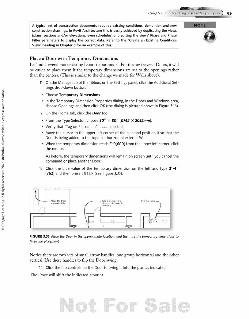
13. Click the blue value of the temporary dimension on the left and type 2 00-4 0000
[762] and then press ENTER (see Figure 3.35).
Notice there are two sets of small arrow handles, one group horizontal and the othervertical. Use these handles to flip the Door swing.
14. Click the flip controls on the Door to swing it into the plan as indicated.
The Door will shift the indicated amount.
FIGURE 3.35 Place the Door in the approximate location, and then use the temporary dimensions tofine-tune placement
Chap t e r 3 • Cr e a t i n g a Bu i l d i n g Lay ou t 139
© C
enga
ge L
earn
ing.
All
right
s res
erve
d. N
o di
strib
utio
n al
low
ed w
ithou
t exp
ress
aut
horiz
atio
n.

Load a Door Family
The next Door that we are going to add is a bi-fold door for the small closet in themiddle of the plan. There is no bi-fold Family available in the current project. There-fore, we will use the Load function to access the Revit Architecture library and load abi-fold Door Family and its Types.
• You should still be in the Door command. If you have canceled it, click the Doortool again.
As noted, if you open the Type Selector, there is only the Single Flush Family and itstypes loaded.
15. On the Modify | Place Door tab, on the Mode panel, click the Load Familybutton.
• In the Load Family dialog, click the Imperial Library [Metric Library] icon on theleft side.
• On the right side, double-click the Doors folder, choose Bifold-2 Panel.rfa[M_Bifold-2 Panel.rfa] and then click Open.
There will be a pause while Revit loads the Family and its types. If during this pro-cess a Save Reminder appears, click Cancel for now.
16. Open the Type Selector.
Notice that there are now two Families shown on the list, each with its own typesindented beneath (see Figure 3.36).
• Verify that “Tag on Placement” is not selected.
17. Move the pointer over the left vertical Wall of the closet in the middle of theplan.
• Using the temporary dimensions, get the Door centered on the vertical Wall.
Do NOT click the mouse to place the door yet.
• Slowly move the mouse left to the right.
FIGURE 3.36 Each Family is listed with an icon preview and its types indented beneath. ChooseBifold-2 Panel : 30 00 3 80 00 [M_Bifold-2 Panel : 0762 3 2032mm].
140 S e c t i o n I I • Cr ea t e t h e Bu i l d i n g Mod e l
© C
enga
ge L
earn
ing.
All
right
s res
erve
d. N
o di
strib
utio
n al
low
ed w
ithou
t exp
ress
aut
horiz
atio
n.

Notice that you can control whether the Door swings into or out of the closet with themouse, but not which side of the opening (up or down in this case) that it swings.Take note of the Status Bar and in some cases a tip that appears on screen. There itnotes that you can use the SPACE BAR to flip the swing.
• Press the SPACE BAR to flip the swing.
• Press it again to flip back (see Figure 3.37).
• When the Door opens to the lower portion of the Wall, click the mouse.
Don’t worry if you added the Door with the wrong swing.We can easily edit this afterthe Door is placed.
18. Click the Modify tool or press the ESC key twice.
19. Save your project.
Flip a Door with Flip Arrows
As we saw above, if you want to flip a Door after it is placed, you can use its handles.
20. Click on the hinged Door at the top right (the first Door placed in the previoussteps above).
21. Click either one of the Flip handles.
• It will pre-highlight and a tip will appear to indicate its function (see Figure 3.38).
FIGURE 3.37 Move the mouse to control Door placement, and press the SPACE BAR to flip the Door
FIGURE 3.38 Flip the instance hand of a Door
Chap t e r 3 • Cr e a t i n g a Bu i l d i n g Lay ou t 141
© C
enga
ge L
earn
ing.
All
right
s res
erve
d. N
o di
strib
utio
n al
low
ed w
ithou
t exp
ress
aut
horiz
atio
n.
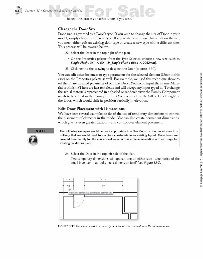
Repeat this process on other Doors if you wish.
Change the Door Size
Door size is governed by a Door’s type. If you wish to change the size of Door in yourmodel, simply choose a different type. If you wish to use a size that is not on the list,you must either edit an existing door type or create a new type with a different size.This process will be covered below.
22. Select the Door in the top right of the plan.
• On the Properties palette, from the Type Selector, choose a new size, such asSingle-Flush : 34 00 3 80 00 [M_Single-Flush : 0864 3 2032mm].
23. Click next to the drawing to deselect the Door (or press ESC).
You can edit other instances or type parameters for the selected element (Door in thiscase) on the Properties palette as well. For example, we used this technique above toset the Phase Created parameter of our first Door. You could input the Frame Mate-rial or Finish. (These are just text fields and will accept any input typed in. To changethe actual materials represented in a shaded or rendered view the Family Componentneeds to be edited in the Family Editor.) You could adjust the Sill or Head height ofthe Door, which would shift its position vertically in elevation.
Edit Door Placement with Dimensions
We have seen several examples so far of the use of temporary dimensions to controlthe placement of elements in the model. We can also create permanent dimensions,which give us even greater flexibility and control over element placement.
NOTE The following examples would be more appropriate in a New Construction model since it isunlikely that we would need to maintain constraints in an existing layout. These tools arecovered here merely for the educational value, not as a recommendation of their usage forexisting conditions plans.
24. Select the Door in the top left side of the plan.
Two temporary dimensions will appear; one on either side—take notice of thesmall blue icon that looks like a dimension itself (see Figure 3.39).
FIGURE 3.39 You can convert a temporary dimension to permanent with the dimension icon
142 S e c t i o n I I • Cr ea t e t h e Bu i l d i n g Mod e l
© C
enga
ge L
earn
ing.
All
right
s res
erve
d. N
o di
strib
utio
n al
low
ed w
ithou
t exp
ress
aut
horiz
atio
n.

25. On the left side dimension, click this icon to make the dimension permanent.
When you do this, a permanent dimension will appear. It will be colored black. Vari-ous colors are used in Revit to indicate various states of selection and/or if the elementis editable. Here is a summary of those colors and what they signify:
• Black—The element is not selected, nor active for editing.
• Purple—The element is pre-highlighted (caused by the mouse passing over it,or the TAB key being used to cycle to the element).
• Light Blue—The element is selected.
• Dark Blue—The element’s value is interactive (for example, temporary dimen-sions, handles and view tags like sections and elevations).
• Orange—Alert color. Indicates an element with an error or warning.
• Magenta—Used for sketch lines in sketch-based elements such as Floors, Roofsand Railings.
NOTESelection color can be customized. On the Application menu, click the Options button. Onthe Graphics tab of the Options dialog, change the colors to suit your preference. Elementcolors can be customized in the Object Styles dialog (Manage tab, Settings panel, ObjectStyles Button).
When you make the temporary dimension permanent, the new dimension appears inblack. However the text stays dark blue as long as the element it is attached to (theDoor in this case) is selected. The new permanent dimension is a new element in thecurrent view (Level 1). To access the options of the new permanent dimension, wemust select it instead of the Door.
26. Click on the new permanent dimension.
The Door will deselect (turning black) and the permanent dimension will select (turn-ing light blue) instead.
• Click the small padlock icon (see the left side of Figure 3.40).
The padlock icon will “close” to indicate that the dimension is now constrained.
27. Click on the Door to select it.
The permanent dimension will deselect (turning black) and the Door will select (turn-ing light blue) instead.
Notice the padlock icon that displays beneath the dimension (see the right side ofFigure 3.40). If you click the blue dimension value and attempt to edit it, an errormessage will display. The only way that you could edit the value would be to first
FIGURE 3.40 Apply a constraint to the Door position using the padlock on the permanent dimension
Chap t e r 3 • Cr e a t i n g a Bu i l d i n g Lay ou t 143
© C
enga
ge L
earn
ing.
All
right
s res
erve
d. N
o di
strib
utio
n al
low
ed w
ithou
t exp
ress
aut
horiz
atio
n.

remove the constraint. You can do this by clicking the closed padlock icon. Let’s testour new constraint with a quick experiment. We will undo it when we are finished.
28. Select the left vertical exterior Wall.
• Move the pointer over the selected Wall (the pointer changes to a small movecursor), click and drag the Wall to the left.
The exact amount is not important.
Notice that theWall moved, and the Door also moved and maintained its dimension.
• Undo the change. (Click the Undo icon on the QAT or press CTRL þ Z).
29. Try the same experiment with the right vertical exterior Wall. Move it to theright.
Notice that the Door on that side did not move. It has no constraints applied to it.
• Undo the change.
NOTE Dimensions are annotation elements. Therefore, they are view-specific—meaning that theyappear only in the view in which they are added. Walls and Doors on the other hand aremodel elements and appear in all views in which they would normally be seen. However, al-though the display of dimensions is view specific, their constraints are not. If the dimensionis locked, the constraint is enforced throughout the model.
Applying an Equality Constraint
Let’s apply another kind of constraint to a different Door. The Door that we have onthe right should be centered in the room.We can add a permanent dimension with anequality constraint to maintain this relationship automatically for us.
30. On the Annotate tab, on the Dimension panel, click the Aligned dimension tool.
We are going to place the dimension ourselves this time because we want more con-trol over the specific witness lines. When you place a dimension, pre-highlight theelements that you wish to dimension. If the wrong element pre-highlights, use theTAB key to cycle to the one you want.
31. Move the mouse over the right exterior vertical Wall.
The Wall centerline will pre-highlight.
• Press TAB and repeat until the inner face of the Wall pre-highlights and thenclick.
• Click the center of the Door next.
The center of the Door should pre-highlight, when it does, click the mouse. Oth-erwise, use the TAB to cycle to the center first.
• Set the final point at the inside face of the vertical Wall on the other side of theroom—remember to use the TAB key if necessary (see Figure 3.41).
144 S e c t i o n I I • Cr ea t e t h e Bu i l d i n g Mod e l
© C
enga
ge L
earn
ing.
All
right
s res
erve
d. N
o di
strib
utio
n al
low
ed w
ithou
t exp
ress
aut
horiz
atio
n.
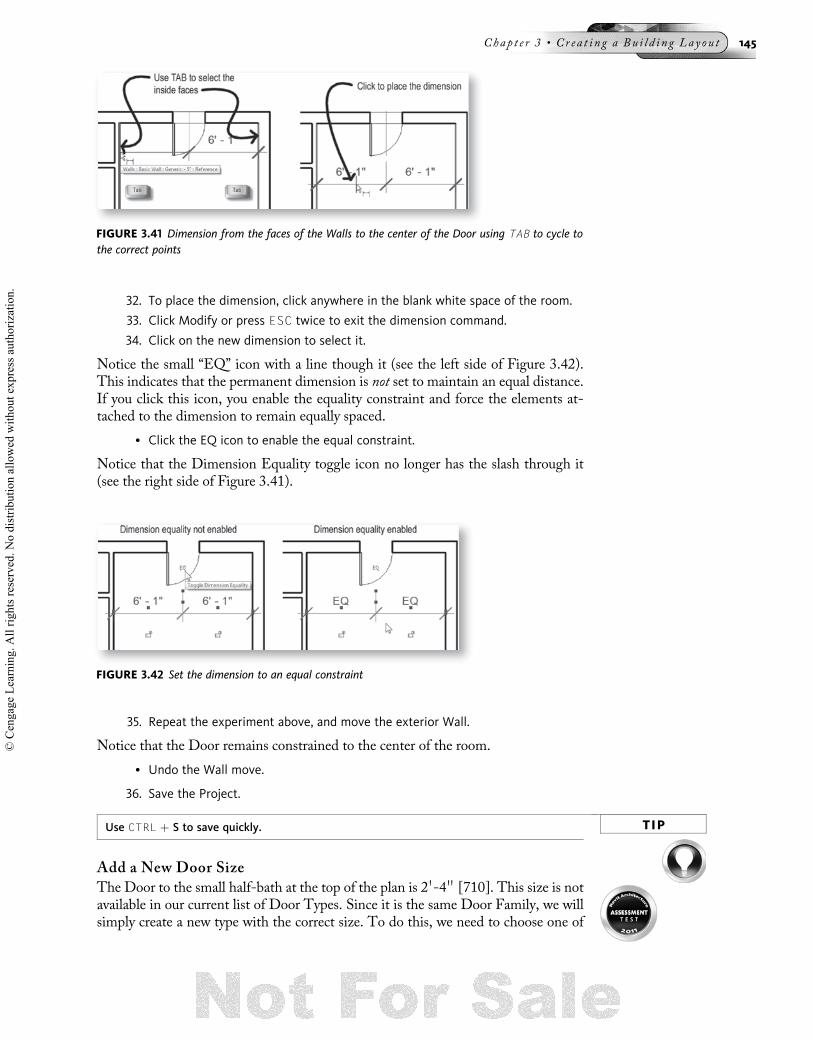
32. To place the dimension, click anywhere in the blank white space of the room.
33. Click Modify or press ESC twice to exit the dimension command.
34. Click on the new dimension to select it.
Notice the small “EQ” icon with a line though it (see the left side of Figure 3.42).This indicates that the permanent dimension is not set to maintain an equal distance.If you click this icon, you enable the equality constraint and force the elements at-tached to the dimension to remain equally spaced.
• Click the EQ icon to enable the equal constraint.
Notice that the Dimension Equality toggle icon no longer has the slash through it(see the right side of Figure 3.41).
35. Repeat the experiment above, and move the exterior Wall.
Notice that the Door remains constrained to the center of the room.
• Undo the Wall move.
36. Save the Project.
TIPUse CTRL þ S to save quickly.
Add a New Door Size
The Door to the small half-bath at the top of the plan is 2 0-4 00 [710]. This size is notavailable in our current list of Door Types. Since it is the same Door Family, we willsimply create a new type with the correct size. To do this, we need to choose one of
FIGURE 3.42 Set the dimension to an equal constraint
FIGURE 3.41 Dimension from the faces of the Walls to the center of the Door using TAB to cycle tothe correct points
Chap t e r 3 • Cr e a t i n g a Bu i l d i n g Lay ou t 145
© C
enga
ge L
earn
ing.
All
right
s res
erve
d. N
o di
strib
utio
n al
low
ed w
ithou
t exp
ress
aut
horiz
atio
n.

the types of this Family, duplicate it, and then edit the size parameters of the dupli-cate Type.
37. On Home tab, click the Door tool.
• From the Type Selector, choose Single Flush: 30 00 3 80 00 [M_Single-Flush : 07623 2032mm].
Don’t place one yet.
• Directly beneath the Type Selector, click the Edit Type button.
The Type Properties dialog will appear. At the top you can see that the Door Familyis Single Flush [M_Single-Flush] and the Type is 30 00 3 80 00 [0762 3 2032mm].The Family list includes all of the Door Families loaded in the current project. Thiscurrently includes only the Single Flush and Bi-fold Families. Next to the Family listis the Load button. You can use this button to load additional Families from externallibraries as we did above. The Type list includes all of the Types available for the se-lected Family. If you scan that list, you will not find the size we need which is 28 00 �80 00 [0710 � 2032mm]. Next to the Type list is the Duplicate button. You use thisbutton to create a copy of the currently selected type. This is how you make a newsize. Duplicate an existing one and edit it. Let’s do that now.
38. Next to the Type list, click the Duplicate button.
TIP A shortcut to this is to press ALT þ D.
A new Name dialog will appear suggesting the name: Single Flush: 30 00 3 80 00 (2)[M_Single-Flush : 0762 3 2032mm (2)].
It is a good idea to change this name. Let’s follow the convention established with theout-of-the-box Families and name this type after its size.
• Change the name to 28 00 3 80 00 [0710 3 2032mm] and then click OK (seeFigure 3.43).
Now that we have created and named a new type, let’s edit it to the size we need.
39. Beneath the Dimensions grouping, for “Width,” type 2 00-4 0000 [762] and thenclick OK.
We are now ready to add a Door using our new Door type.
40. On the ribbon, verify that “Tag on Placement” is not selected.
• Add a Door to the small half-bath at the top of the plan.
• Use the SPACE BAR to swing the door in to the right (see Figure 3.44).
FIGURE 3.43 Create a new Type by Duplicating an existing one
146 S e c t i o n I I • Cr ea t e t h e Bu i l d i n g Mod e l
© C
enga
ge L
earn
ing.
All
right
s res
erve
d. N
o di
strib
utio
n al
low
ed w
ithou
t exp
ress
aut
horiz
atio
n.

Add the Remaining Doors
41. Using Figure 3.45 as a guide and the techniques covered above, place theremaining doors in the plan.
HINTYou can select a Door, right-click, and choose Create Similar as a way of quickly addingDoors of the same type (with similar parameters).
42. Save the project.
Add Windows
Working withWindows is nearly identical to working with Doors. Many of the para-meters are the same, and placement and manipulation ofWindows works the same aswith Doors.
43. On the Home tab, click the Window tool.
All of the options for placing Windows match those of Doors. For detailed descrip-tions of each of these options, see Figure 3.32 above and the accompanyingdescriptions.
FIGURE 3.45 Add the remaining Doors as shown
FIGURE 3.44 Add a Door in the new Type to the half-bath
Chap t e r 3 • Cr e a t i n g a Bu i l d i n g Lay ou t 147
© C
enga
ge L
earn
ing.
All
right
s res
erve
d. N
o di
strib
utio
n al
low
ed w
ithou
t exp
ress
aut
horiz
atio
n.

The only Window Family loaded in the current project is the Fixed Family. Thishouse has double hung windows. Let’s see what we have in the library.
44. On the Place Window tab, on the Mode panel, click the Load Family button.
• In the Load Family dialog, click the Imperial Library [Metric Library] icon on theleft side.
• On the right side, double-click the Windows folder, choose Double Hung.rfa[M_Double Hung.rfa] and then click Open.
The size that we need is not included on the list. So as we did above for the Door, wewill create a new Double Hung window type.
• From the Type Selector, choose Double Hung : 36 00 3 48 00 [M_Double Hung :0915 3 1220mm].
45. On the Properties palette, right beneath the Type Selector, click the Edit Typebutton.
• Next to the Type list, click the Duplicate button (or press ALT þ D).
• Change the name to 36 00 3 56 00 [0915 3 1422mm] and then click OK.
• Beneath the Dimensions grouping, for “Height,” type 4 00-8 0000 [1422] and thenclick OK.
• On the ribbon, click the Tag on Placement button to deselect it.
46. Using Figure 3.46 as a guide and the techniques covered above, place theWindows indicated.
• Use the new type that you just created for all of these Windows.
Note that the Window in the lower left corner is placed at the midpoint of the Wall.The temporary dimensions should automatically snap to a centered configuration asyou move the mouse nearby. This can also be done easily by making a permanentdimension as above and then clicking the EQ constraint.
47. Using the process covered here, create two new Window types:
• 36 00 3 32 00 [0915 3 0800mm] (width x height)
• 24 00 3 32 00 [0600 3 0800mm] (width x height)
48. Place the remaining two windows as shown in Figure 3.47.
FIGURE 3.46 Add several Windows to the plan
148 S e c t i o n I I • Cr ea t e t h e Bu i l d i n g Mod e l
© C
enga
ge L
earn
ing.
All
right
s res
erve
d. N
o di
strib
utio
n al
low
ed w
ithou
t exp
ress
aut
horiz
atio
n.

49. Save the project.
Add Cased Openings
There are several passages between the hallway and the neighboring rooms that aresimply cased openings. You place these the same way as Doors—in fact they arestored in the Doors folder, but they are categorized as Generic Models so that theywill not appear in Door Schedules. The element includes the casing and a hole inthe Wall, but no Door panel.
50. On the Home tab, click the Component tool.
Components are used to represent many things including furniture, fixtures, parkingspaces, and nearly anything else you can imagine. In this case, the Cased Openingcomponents that we need are not currently loaded in the model.
• On the Modify | Place Component tab, on the Mode panel, click the Load Familybutton.
• In the Load Family dialog, click the Imperial Library [Metric Library] icon on theleft side.
• On the right side, double-click the Doors folder, choose Opening-Cased.rfa[M_Opening-Cased.rfa] and then click Open.
NOTERemember, the Cased Opening Families are stored in the Doors folder and are essentiallyDoor elements, but they have been categorized as Components (Generic Models) insteadbecause typically you would not want cased openings to appear on Door Schedules.
• From the Type Selector, choose Cased Opening : 30 00 3 80 00 [M_Opening-Cased : 0762 3 2032mm].
51. Using Figure 3.48 as a guide, place four Openings in the locations indicated.
TIPUse the temporary dimensions to place them 6 0000 [150] from the intersection with the otherWalls. The horizontal opening at the top should be centered.
FIGURE 3.47 Create two new custom types and then place the remaining two Windows
Chap t e r 3 • Cr e a t i n g a Bu i l d i n g Lay ou t 149
© C
enga
ge L
earn
ing.
All
right
s res
erve
d. N
o di
strib
utio
n al
low
ed w
ithou
t exp
ress
aut
horiz
atio
n.

After placement, you can click on a Cased Opening and move it or edit it just like theDoors and Windows.
Load a Custom Family
There is one additional Window in the existing house that we need to add. In thefront of the house in the living room (right side at the bottom) is a picture windowcomprised of a fixed Window flanked by two double-hung units. We could add thisas three Windows simply enough. However, it is better to use a single Family thatcontains the three Windows. To save time, this configuration of three Windows hasbeen pre-assembled and saved as a Family file and included with the Chapter 3 data-set files from the student companion. In this sequence, we will load this Family intoour current project and add it to the front of the existing house.
52. On the Home tab, click the Window tool.
• On the Modify | Place Window tab, on the Mode panel, click the Load Familybutton.
53. In the Load Family dialog, browse to the location where you installed the data-set files from the student companion and open the MasterRAC 2011\Chapter03folder.
• Choose Existing Living Room Front Window.rfa [Existing Living Room FrontWindow-Metric.rfa] and then click Open.
• Add the Window to the bottom horizontal Wall in the room at the right (seeFigure 3.49).
FIGURE 3.48 Add Openings to the hallway
150 S e c t i o n I I • Cr ea t e t h e Bu i l d i n g Mod e l
© C
enga
ge L
earn
ing.
All
right
s res
erve
d. N
o di
strib
utio
n al
low
ed w
ithou
t exp
ress
aut
horiz
atio
n.

This Family is a very simple one that contains three Window elements. This can bethought of as a “nested” Family because the Family file contains instances of otherFamilies. We will explore Families in more detail in Chapter 10.
• Click Modify or press ESC twice.
54. Save the project.
Modifying Door Size and Type
Modifying Doors and Windows is easy. We have already covered most of the basictechniques above. It turns out that the Door in the top right of the plan (the first onewe added) is supposed to be a double door. Furthermore, it is actually a French doorleading out to an existing patio. Let’s make this edit to our model.
55. On the Insert tab, on the Load from Library panel, click the Load Family button.
• In the Load Family dialog, click the Imperial Library [Metric Library] icon on theleft side.
• On the right side, double-click the Doors folder, choose Double-Glass 2.rfa[M_Double-Glass 2.rfa] and then click Open.
56. Select the Single Hinged door at the top right corner of the plan (the first onewe added).
• On the Properties palette, from the Type Selector, choose 68 00 3 80 00 [1730 32032mm].
NOTEYou can use this technique for Windows and other elements as well.
The new Door Type has replaced the previous one and remains nicely centered sincewe added that constraint to this Door earlier. In plan view, it is not obvious whateffect choosing a glass Door Family had. To see the glass, we will have to view themodel in 3D.
VIEWING THE MODEL IN 3DWe have spent the entire chapter working in a single plan view. However, as we sawin previous chapters, you can add or edit elements in any view you wish and then viewthem or edit them in elevation, section, and/or three-dimensional views. Revit
FIGURE 3.49 Create an Instance of the imported Family at the front of the house
Chap t e r 3 • Cr e a t i n g a Bu i l d i n g Lay ou t 151
© C
enga
ge L
earn
ing.
All
right
s res
erve
d. N
o di
strib
utio
n al
low
ed w
ithou
t exp
ress
aut
horiz
atio
n.

Architecture maintains all of the parameters of our building model including thoserequired to view it in 3D, even if we don’t explicitly ask it to!
Open the Default Three-Dimensional View
Let’s have a look at how the model is shaping up in the third dimension.
1. On the View tab, click the Default 3D View icon. (Choose Default 3D, notCamera or Walkthrough).
TIP You can also find this icon on the QAT.
A new view will appear on screen named: {3D}. This name is assigned automaticallyto the default 3D view in Revit. The default 3D view is an axonometric of the com-plete building model looking from the south-east. This view appears in the ProjectBrowser beneath the 3D Views category. From the default view, we can see thegangedWindow that we added above in the front of the house. Even though the gra-phics in the Floor Plan view indicated that the middle Window was different fromthe two flanking Windows, from the 3D vantage point it is now very clear that themiddle Window is fixed while the two flanking ones are double-hung.
You can dynamically pan and/or zoom any view as we have already seen. In a 3Dview, you can also “orbit” the view. When you do this, you can change the angle andheight from which we are viewing the model and virtually spin it in all threedimensions.
2. Within the view window on the Navigation Bar, click the Steering Wheel icon(see Figure 3.50).
TIP The keyboard shortcut for Steering Wheels is the F8 key.
FIGURE 3.50 Display the Default 3D view and manipulate it dynamically with the Steering Wheel
152 S e c t i o n I I • Cr ea t e t h e Bu i l d i n g Mod e l
© C
enga
ge L
earn
ing.
All
right
s res
erve
d. N
o di
strib
utio
n al
low
ed w
ithou
t exp
ress
aut
horiz
atio
n.

Note the Steering Wheel appears on screen and follows the movement of the cursor.The Steering Wheel has several controls. Among them are: Pan, Zoom, and Orbit.We explored several of these back in Chapter 1. By now you should already be com-fortable with panning and zooming. Orbit is only available in a 3D view. In otherwords, you can open the Steering Wheel from any view such as the Floor Plan viewLevel 1 that we have worked in throughout the chapter. When you do, only Zoomand Pan will appear. Let’s give Orbit a try in our 3D view.
• Move your mouse pointer over the Orbit portion of the Steering Wheel; clickand hold down the mouse button and then drag to orbit.
The pointer will change to an orbit icon to indicate that this mode is active. APivot point icon will also appear on screen.
• In the middle of the Steering Wheel, move your mouse pointer over the Centerportion; click and drag over the model to relocate the pivot point.
In the Orbit mode, drag side to side to rotate the model and drag up or down totilt the vantage point up or down. The Look mode functions similarly. Give it a try.
3. Orbit the model around so that you can see the back of the house.
• Pan and Zoom to fine-tune the view to your liking.
4. On the View Control Bar (bottom left corner of each view window) click theModel Graphic Style icon and choose Shading with Edges from the pop-upmenu that appears (see Figure 3.51).
TIPThe dynamic viewing functions can also be performed with a wheel mouse and the CTRLand SHIFT keys. Drag with the mouse wheel held down to pan, Hold down the CTRL keyand drag with the wheel, or simply roll the wheel to zoom. Hold down the SHIFT key anddrag with the wheel to orbit. Your specific mouse and mouse driver will determine the exactbehavior. Mouse drivers by many manufacturers allow customization of specific buttonfunctions. Sorry, 3D Connexion devices are not yet supported.
TIPThe keyboard shortcut for Shading with Edges is SD. The keyboard shortcut for Hidden Lineis HL.
Revit 2011 adds two new shading modes. We now have Consistent Colors and Real-istic. Consistent Colors shows the edges like Shaded with Edges but uses a consistenttone for each color rather than tinting them as the geometry changes angle to the
FIGURE 3.51 Change the view to Shading with Edges
Chap t e r 3 • Cr e a t i n g a Bu i l d i n g Lay ou t 153
© C
enga
ge L
earn
ing.
All
right
s res
erve
d. N
o di
strib
utio
n al
low
ed w
ithou
t exp
ress
aut
horiz
atio
n.

vantage point. Realistic takes advantage of the rendering features of Materials in Re-vit and displays any photorealistic textures in the viewport onscreen. In our case, theWalls we are using do not have any textures applied, so this mode would not enhanceour viewing much at this time. However, as the project progresses, we will revisit theshading modes and try our Realistic once we have some Materials assigned to ourmodel.
The default three-dimensional view: {3D} is always available. You could certainly usethis view exclusively and simply orbit, scroll, and zoom the view as needed each timeyou displayed it. However, once you get a 3D view displaying just the way you like,you are encouraged to save the view. The new view will be added to the ProjectBrowser beneath the 3D views category along with any other 3D views your projecthas. To do this, right-click on {3D} beneath 3D views in the Project Browser andchoose Rename. Give a descriptive name. If you then click the Default 3D viewicon again, a new default {3D} view will be created. If you click the 3D view iconand the default {3D} view already exists, it will open this existing view instead of cre-ating a new one.
5. Save your modified 3D view.
• Right-click the name {3D} beneath 3D Views on the Project Browser and chooseRename.
• Give the new view a unique name such as “Rear Existing French Door.”
Edit in Any View
From our explorations in 3D, you may have noticed that many of the interior Wallsare the wrong height. We can correct this easily.
6. Close your “Rear Existing French Door” view and then click the Default 3D viewicon to create a new {3D} view.
• On the View tab, on the Windows panel, click the Window Tile icon.
TIP The keyboard shortcut for Tile is WT.
• Orbit the view down slightly so that you can clearly see the heights of the inte-rior partitions.Remember, in addition to the techniques already covered, you can orbit 3Dviews by dragging the ViewCube. On the Navigation Bar, choose Zoom .Zoom All to Fit.
TIP The keyboard shortcut for Zoom All to Fit is ZA.
7. Activate the View: Floor Plan: Level 1 by clicking anywhere in the view or theview’s title bar and then use the Modify tool to create a selection window, clickwithin the exterior walls and drag from right to left to select all interior Walls.
Be sure to select only the interior Walls and not any of the exterior ones. Do notworry about selecting Doors and Openings. We will remove them from the selectionnext.
All of the selected elements will highlight in light blue in both views (see Figure 3.52).
154 S e c t i o n I I • Cr ea t e t h e Bu i l d i n g Mod e l
© C
enga
ge L
earn
ing.
All
right
s res
erve
d. N
o di
strib
utio
n al
low
ed w
ithou
t exp
ress
aut
horiz
atio
n.

8. In the far right corner of the Status Bar, click the Filter Selection icon.
NOTEThe quantity of selected elements will appear next to the Filter icon. In the figure, the selec-tion currently contains 21 elements.
• In the Filter dialog, remove the checkmarks from all boxes except “Walls” andthen click OK (see Figure 3.53).
9. On the Properties palette, beneath the Constraints grouping, for “Top Con-straint,” click in the empty cell to the right, click the drop-down arrow, chooseUp to level: Level 2 and then click OK (see Figure 3.54).
FIGURE 3.52 Select all interior Walls
FIGURE 3.53 Now only the Walls will be highlighted.
Chap t e r 3 • Cr e a t i n g a Bu i l d i n g Lay ou t 155
© C
enga
ge L
earn
ing.
All
right
s res
erve
d. N
o di
strib
utio
n al
low
ed w
ithou
t exp
ress
aut
horiz
atio
n.

Note that even though we made the change from a 2D floor plan view, the edit ap-peared in the 3D view immediately. In Revit, every view is always up to date. There isno need to coordinate or refresh anything. Regardless of the view you are working in,all edits apply directly to the model. You simply choose the most convenient and log-ical view in which to work and Revit takes care of the rest.
In this exercise, we have constrained the top of the interior Walls to the height of thesecond floor. It turns out that the default template from which we started our projectincluded two levels. However the height of those levels does not match the existingconditions of our residential project. We will adjust the height of the levels, and in sodoing, all of these interior partitions will automatically adjust with the level height.This is the primary reason to apply such a constraint.
10. On the Project Browser, double-click the East elevation view to open it.
Your windows should still be tiled on screen.
• Position the view so that you can clearly see Level heads on the right side andthe 3D view in the background.
11. Click on Level 2 to select it.
• Click again directly on the blue dimension text beneath the Level 2 label.
The text will highlight—ready to receive input.
• Change the value to 9 00-0 0000 [1800] and then press ENTER (see Figure 3.55).
Notice the immediate change to all of the interior Walls in the 3D view.
FIGURE 3.54 Set the Top Constraint of the interior Walls to Level 2
156 S e c t i o n I I • Cr ea t e t h e Bu i l d i n g Mod e l
© C
enga
ge L
earn
ing.
All
right
s res
erve
d. N
o di
strib
utio
n al
low
ed w
ithou
t exp
ress
aut
horiz
atio
n.

12. Maximize the Floor Plan: Level 1 view.
• Zoom the window to fit. On the View tab, in the Windows panel, click the CloseHidden button.
When you have many open windows, they can all be closed except the current oneusing this command. This helps keep your interface organized and preserves memoryand computer resources.
13. Save your project.
ADDING PLUMBING FIXTURESThe small half-bath in the top of our plan could use some fixtures. The library ofcomponents provided with Revit includes a variety of items such as furniture, toilets,trees, parking lot layouts, equipment, electrical fixture symbols, targets, tags, andmuch more. All of these items are Families and many have special behaviors andparameters appropriate to the object that they represent. In this exercise, we will sim-ply load the Families we need and insert them in the model much like we did for theganged Window and cased openings above.
Add Components to the Model
You add Components like plumbing fixtures and furniture in nearly the same way asDoors, Windows and Openings. Each Family may vary slightly depending on theparameters built into it. However, the basic process is the same: click the Component
tool on the Home tab, choose an item from the Type Selector or click the Load Fam-ily button to access the library. Place the item in your model.
1. On the Home tab, click the Component tool.
If you open and scroll through the Type Selector, you will note that no plumbingfixture Families currently appear on the list.
As we did above for Doors andWindows, we will simply load the items we need fromthe library.
2. On the Modify | Place Component tab, on the Mode panel, click the Load Familybutton.
• In the Open dialog, click the Imperial Library [Metric Library] icon on the left side.
• On the right side, double-click the Plumbing Fixtures folder.
FIGURE 3.55 Adjust the height of Level 2 and see the immediate effect on the interior Walls
Chap t e r 3 • Cr e a t i n g a Bu i l d i n g Lay ou t 157
© C
enga
ge L
earn
ing.
All
right
s res
erve
d. N
o di
strib
utio
n al
low
ed w
ithou
t exp
ress
aut
horiz
atio
n.

You will note that two Family files exist for domestic toilets, one for 2D and the otherfor 3D. The reason for this is that in many cases, you will not need to see plumbingfixtures in 3D. By using a 2D symbol in those cases, you can reduce demand on com-puter resources in the project file. In reality, in a model the size of the one that we arebuilding here, there would be no noticeable difference in performance from using ei-ther Family. However, let’s begin developing good BIM habits right away. Since wehave no need for a 3D toilet in this particular project, let’s load the 2D Family for thisexercise. Like all Families, you can swap out the 2D Component later with a 3D oneshould project needs change.
MANAGERNOTE
It should be noted that the “3D” plumbing fixtures actually contain a 2D symbol that appearsonly in floor plan views and a 3D symbol that appears only in the 3D views. Revit automati-cally switches between the appropriate representations as needed. When you create a Build-ing Information Model, it is important to recognize techniques such as this and to realizethat “Model” does not always mean “3D.” Nor does “Model” imply that every facet andscrew of an item should be painstakingly represented in graphical form. Always rememberto strike a balance between what is conveyed graphically and what is conveyed by othermeans such as with attached data parameters—this is the “I” in BIM. In many cases, an “In-formation” model is much more practical and useful to a project team than a “3D” model.There are many types of models. Statisticians and economists refer to their spreadsheets as“models.” Meteorologists refer to their predictions and weather simulations as “models.” AsArchitects, we tend to only think “3D” when the word model is mentioned. Learning to em-brace BIM means understanding that a model is not always 3D, and that the “I” is just as im-portant as, and sometimes more important than, the “M.” A really good BIM will includeboth a graphical and data model tightly integrated with one another. Model in this contexttherefore can more accurately be described as a “representation” or a “simulation” of ourbuilding project.
• Choose Toilet-Domestic-2D.rfa [M_Toilet-Domestic-2D.rfa] and then click Open.If you get a warning: “No tag Loaded,” simply click No to continue. Like Doorsand Windows above, the Component tool can Tag on Placement as well.
3. Zoom in on the half-bath at the top of the plan.
• Move the pointer around the four Walls of the half-bath.
Notice how the Toilet automatically orients itself to theWalls (see Figure 3.56). Thisis because the 2D toilet is a wall-hosted Family. The Doors and Windows we addedalready were also wall-hosted Families, but they also cut holes in theWalls. Naturallythe toilet does not need to cut theWall, but requiring the attachment is a nice feature.If you move your mouse away from the Wall, the cursor changes to indicate thatplacement is not allowed. It is also possible to create Families that are hosted andnot hosted. Refer to Chapter 10 for more information.
158 S e c t i o n I I • Cr ea t e t h e Bu i l d i n g Mod e l
© C
enga
ge L
earn
ing.
All
right
s res
erve
d. N
o di
strib
utio
n al
low
ed w
ithou
t exp
ress
aut
horiz
atio
n.

• Click a point on the left vertical Wall to place the toilet in the model.
This toilet room is clearly not up to code! Just place the toilet very close to theintersection with the exterior Wall. We still need room for a small sink.
4. On the Place Component tab, click the Load Family button again.
Return to the same location and Open the Sink-Single-2D.rfa [M_Sink-Single-2D.rfa] Family this time.
Move the pointer around again and notice that this Component is also hosted. How-ever, it will be too big for the space that we have available. Sometimes what we find inthe field does not meet current building codes. The sink in this existing half-bath isvery small.
5. On the Properties palette, click the Edit Type button.
• Next to the Type list, click the Duplicate button (or press ALT þ D).
• Change the name to 18 00 � 15 00 [450 � 375mm] and then click OK.
• Beneath the Dimensions grouping, for “Depth,” type 1 00-3 0000 [375].
TIPRemember, if you are using Imperial units, you can simply type 1 3 with a space between thenumbers, and Revit Architecture will interpret this as 1’-3 00.
• Beneath the Dimensions grouping, for “Width,” type 1’-6 0000 [450] and then clickOK.
6. Place the sink next to the toilet. Use the temporary dimensions to fine-tune theplacement of both the sink and the toilet.
It will be a tight fit. You will need to set the values of the temporary dimensions toabout 1 00 [25] between the Walls and the Components to get everything to fit (seeFigure 3.57).
TIPYou can also select the element and “nudge” it with the arrow keys on your keyboard tomove it. The element will move approximately 2mm on screen. The more you are zoomedinto the view the smaller the distance each press of the arrow key will move the object.
FIGURE 3.56 The Toilet Family is wall-hosted, so it automatically attaches to the Walls
Chap t e r 3 • Cr e a t i n g a Bu i l d i n g Lay ou t 159
© C
enga
ge L
earn
ing.
All
right
s res
erve
d. N
o di
strib
utio
n al
low
ed w
ithou
t exp
ress
aut
horiz
atio
n.

7. Click the Modify tool or press the ESC key twice.
8. Save the project.
CREATE AN IN-PLACE FAMILYThe first floor existing conditions plan is nearly finished. We still need to add thefireplace in the living room and stairs in the middle of the plan. While it would bepossible to create a fireplace Family in the Family Editor and save it in our libraryfor use in any project, this would only make sense if we used the same fireplace designoften. If you design a lot of homes that use the same fireplace, this is exactly what youshould do. Refer to techniques in Chapter 10 to learn how to create a loadable com-ponent Family.
In this case, we will create the exact fireplace we need for this project directly in-place.This is called an “In-Place Family.”
NOTE In-Place Families are not designed to be moved, copied, rotated, etc. They are meant to beused only once. If you need to use it more than once within this project or in a differentproject, a regular loadable component Family should be created in the Family Editor, savedto a library and then loaded into your project as needed. The Family Editor will be exploredin detail in Chapter 10.
Create an In-Place Family and Choose a Category
To get started, we will create a new In-Place Family and assign it to a pre-definedcategory. Revit has a long list of predefined categories. Categories are at the top ofthe hierarchy discussed in the “Families & Types” topic in Chapter 1.
1. Zoom in on the middle of the right vertical exterior Wall.
This is where our fireplace will go.
2. On the Home tab, click the pop-up on the Component tool.
• On the Modify | Place Component tab, on the Mode panel, click the Model In-Place tool.
• In the “Family Category and Parameters” dialog, choose Generic Models andthen click OK (see Figure 3.58).
FIGURE 3.57 Use the Temporary Dimensions to fine-tune placement of the Components
160 S e c t i o n I I • Cr ea t e t h e Bu i l d i n g Mod e l
© C
enga
ge L
earn
ing.
All
right
s res
erve
d. N
o di
strib
utio
n al
low
ed w
ithou
t exp
ress
aut
horiz
atio
n.

The Family Category list is a fixed list built into the software. When you create aFamily, you must assign it one of these categories. The Family you create will gainthe characteristics of the category to which it is assigned. In general, when choosinga category, try to select the one that most closely matches the actual object that you arecreating. The Construction Specifications Institute (CSI) spec section for fireplaces isDivision 10—Specialties (10300 Fireplaces and Stoves), which would tempt us tochoose “Specialty Equipment.”However, your choice of category does impart certainbehaviors to your Family. Specialty Equipment is intended more for free-standingequipment items and does not have a “cut” representation. Items like 10340 Manu-factured Exterior Specialties, 10500 Lockers or 10670 Storage Shelving are all exam-ples of things that would work well in the Specialty Equipment category. Items inRevit that are “cutable” interact with the cut plane of floor plan and section viewsand show bold when cut and lighter when viewed in projection. Since we will wantour fireplace to interact with the Wall and appear bolder when cut in plan, we need acategory that supports the cut plane.
To get the cutting behavior, we will use the “Generic Models” category instead. Thisis sort of a “catch all” category. You typically choose Generic Models when the itemyou are modeling does not fit neatly into any of the other categories. Generic Modelsdoes not impart any specialized parameters that might be available from other moredescriptive categories, but aside from the need for interaction with the cut plane, ourexisting fireplace has no other specialized needs.
• In the Name dialog, type: Existing Fireplace and then click OK.
You are now in “In-Place Family Editing”mode. The model will gray out but remainvisible for reference. The ribbon tabs will change showing a collection of In-PlaceFamily editing tools in place of their usual tools. Take a look at the Home tab forexample. If you expand the Project Browser, you will find the new Family listed underGeneric Model (see Figure 3.59).
FIGURE 3.58 Create an In-Place Family and choose its category
Chap t e r 3 • Cr e a t i n g a Bu i l d i n g Lay ou t 161
© C
enga
ge L
earn
ing.
All
right
s res
erve
d. N
o di
strib
utio
n al
low
ed w
ithou
t exp
ress
aut
horiz
atio
n.
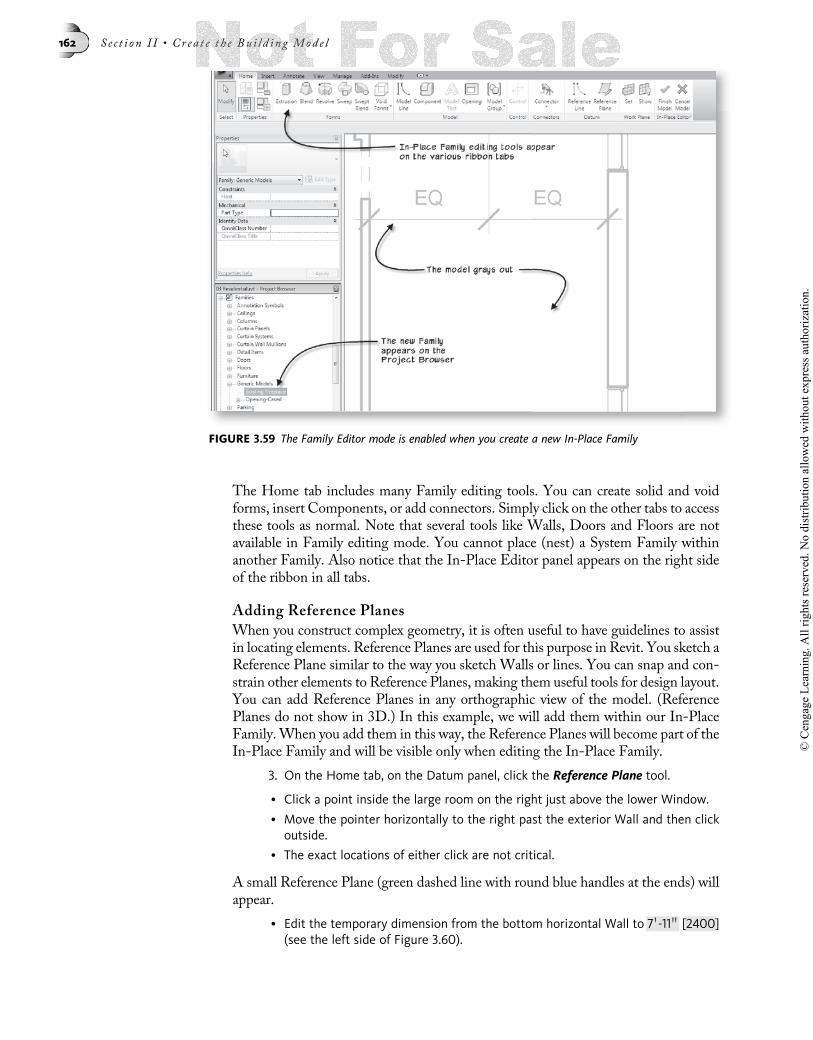
The Home tab includes many Family editing tools. You can create solid and voidforms, insert Components, or add connectors. Simply click on the other tabs to accessthese tools as normal. Note that several tools like Walls, Doors and Floors are notavailable in Family editing mode. You cannot place (nest) a System Family withinanother Family. Also notice that the In-Place Editor panel appears on the right sideof the ribbon in all tabs.
Adding Reference Planes
When you construct complex geometry, it is often useful to have guidelines to assistin locating elements. Reference Planes are used for this purpose in Revit. You sketch aReference Plane similar to the way you sketch Walls or lines. You can snap and con-strain other elements to Reference Planes, making them useful tools for design layout.You can add Reference Planes in any orthographic view of the model. (ReferencePlanes do not show in 3D.) In this example, we will add them within our In-PlaceFamily.When you add them in this way, the Reference Planes will become part of theIn-Place Family and will be visible only when editing the In-Place Family.
3. On the Home tab, on the Datum panel, click the Reference Plane tool.
• Click a point inside the large room on the right just above the lower Window.
• Move the pointer horizontally to the right past the exterior Wall and then clickoutside.
• The exact locations of either click are not critical.
A small Reference Plane (green dashed line with round blue handles at the ends) willappear.
• Edit the temporary dimension from the bottom horizontal Wall to 7 0-11 00 [2400](see the left side of Figure 3.60).
FIGURE 3.59 The Family Editor mode is enabled when you create a new In-Place Family
162 S e c t i o n I I • Cr ea t e t h e Bu i l d i n g Mod e l
© C
enga
ge L
earn
ing.
All
right
s res
erve
d. N
o di
strib
utio
n al
low
ed w
ithou
t exp
ress
aut
horiz
atio
n.
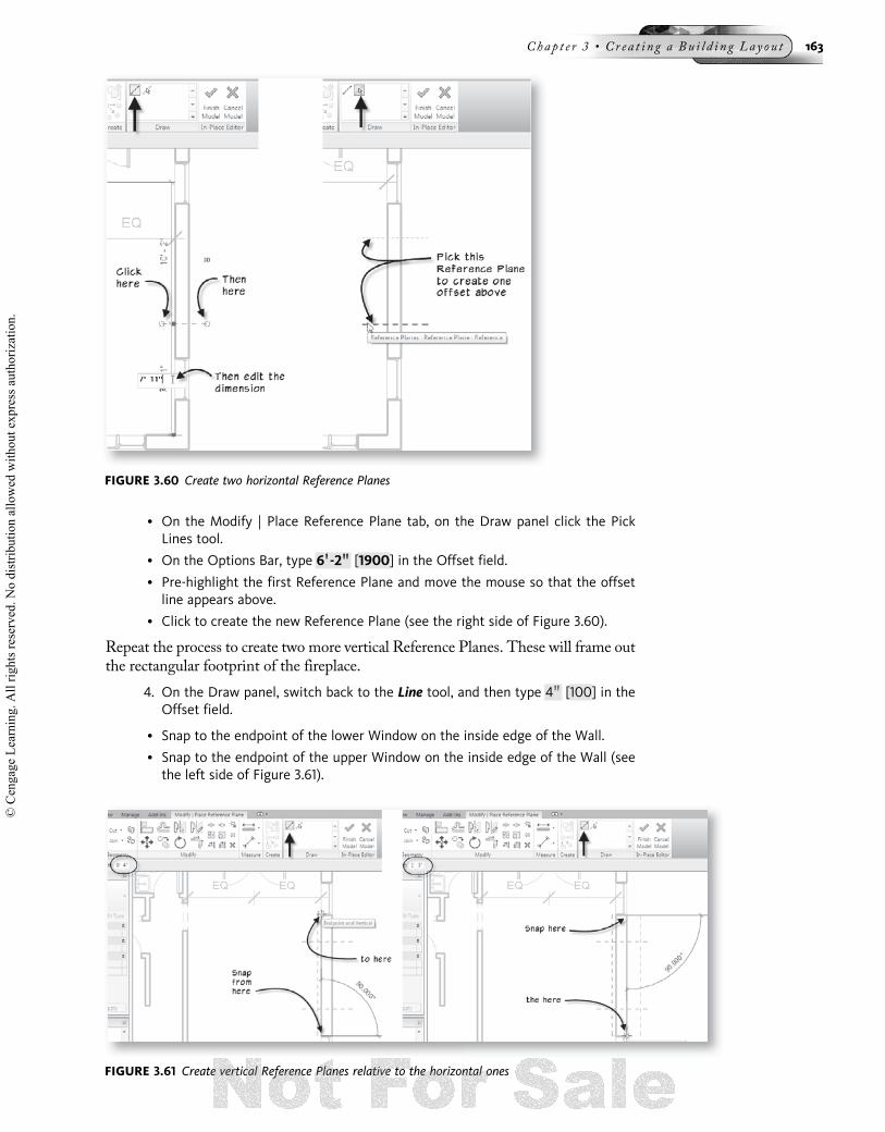
• On the Modify | Place Reference Plane tab, on the Draw panel click the PickLines tool.
• On the Options Bar, type 6 00-2 0000 [1900] in the Offset field.
• Pre-highlight the first Reference Plane and move the mouse so that the offsetline appears above.
• Click to create the new Reference Plane (see the right side of Figure 3.60).
Repeat the process to create two more vertical Reference Planes. These will frame outthe rectangular footprint of the fireplace.
4. On the Draw panel, switch back to the Line tool, and then type 4 00 [100] in theOffset field.
• Snap to the endpoint of the lower Window on the inside edge of the Wall.
• Snap to the endpoint of the upper Window on the inside edge of the Wall (seethe left side of Figure 3.61).
FIGURE 3.60 Create two horizontal Reference Planes
FIGURE 3.61 Create vertical Reference Planes relative to the horizontal ones
Chap t e r 3 • Cr e a t i n g a Bu i l d i n g Lay ou t 163
© C
enga
ge L
earn
ing.
All
right
s res
erve
d. N
o di
strib
utio
n al
low
ed w
ithou
t exp
ress
aut
horiz
atio
n.
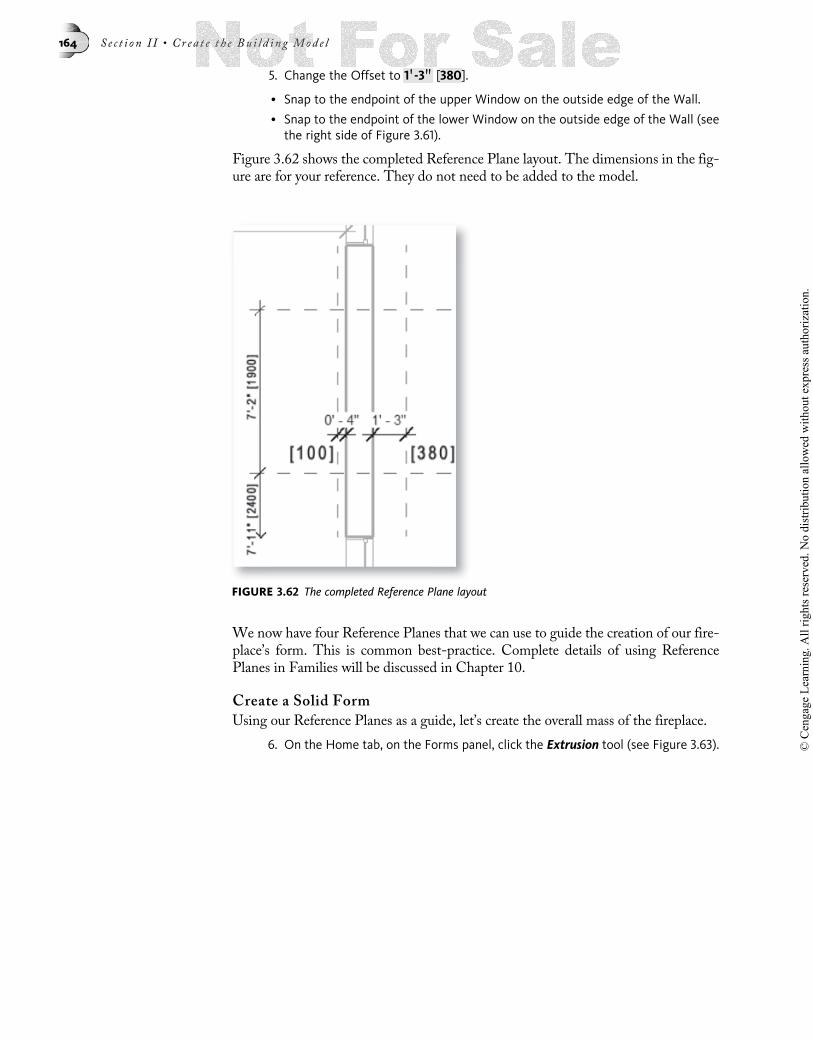
5. Change the Offset to 1 00-3 0000 [380].
• Snap to the endpoint of the upper Window on the outside edge of the Wall.
• Snap to the endpoint of the lower Window on the outside edge of the Wall (seethe right side of Figure 3.61).
Figure 3.62 shows the completed Reference Plane layout. The dimensions in the fig-ure are for your reference. They do not need to be added to the model.
We now have four Reference Planes that we can use to guide the creation of our fire-place’s form. This is common best-practice. Complete details of using ReferencePlanes in Families will be discussed in Chapter 10.
Create a Solid Form
Using our Reference Planes as a guide, let’s create the overall mass of the fireplace.
6. On the Home tab, on the Forms panel, click the Extrusion tool (see Figure 3.63).
FIGURE 3.62 The completed Reference Plane layout
164 S e c t i o n I I • Cr ea t e t h e Bu i l d i n g Mod e l
© C
enga
ge L
earn
ing.
All
right
s res
erve
d. N
o di
strib
utio
n al
low
ed w
ithou
t exp
ress
aut
horiz
atio
n.

7. On the Options Bar, in the “Depth” field, type 9 00-0 0000 [2750].
• On the Draw panel, for the sketch shape, click the Rectangle icon.
8. Snap to the intersection of two of the Reference Planes and then snap to anopposite intersection to define the rectangular shape (see Figure 3.64).
An open padlock icon will appear on each side of the shape. If we wanted to constrainthe sides to the Reference Planes, we could click these locks. There is no need forexplicit (deliberate) constraints here so we will not do that for this exercise.
9. On the Modify | Create Extrusion tab, on the Mode panel, click the Finish but-ton (large green checkmark).
This gives us our basic fireplace mass. We now need to carve out the firebox.
Create a Void Form
Using the same basic process, we can create a Void form that will carve away from thesolid form in our Family giving us the firebox opening.
FIGURE 3.63 Create an Extrusion.
FIGURE 3.64 Sketch the overall shape of the extrusion
Chap t e r 3 • Cr e a t i n g a Bu i l d i n g Lay ou t 165
© C
enga
ge L
earn
ing.
All
right
s res
erve
d. N
o di
strib
utio
n al
low
ed w
ithou
t exp
ress
aut
horiz
atio
n.

10. On the Home tab, click the Void Forms drop-down button and then chooseVoid Extrusion.
The Modify | Create Void Extrusion tab will appear with the same Sketch tools asbefore.
11. On the Options Bar, in the “Depth” field, type 4 00-0 0000 [1200].
• On the Draw panel, click the Pick Lines icon.
• Click the left vertical edge of the Solid Extrusion.
A magenta sketch line will appear directly on top of this edge.
12. On the Options Bar, change the Offset value to 1 00-1 0000 [325].
• Click the right edge of the Solid Extrusion to create a magenta sketch linewithin the fireplace structure.
• Change the Offset value to 1 00-5 0000 [430] and click the top edge to create a sketchline below it.
• Click the bottom edge of the Solid Extrusion to create a sketch line above it (seeFigure 3.65).
The side of the offset will pre-highlight before you click so that you can be sure tooffset the sketch line to the correct side. Notice that the lines automatically trimwhen you offset more lines. If yours do not trim exactly the way they are illustratedin the figure, you can simply use the Trim tool on the Modify tab to clean up thesketch.
Now we will use the Trim tool (the same one we used for Walls at the start of thechapter) to cleanup the sketch (form a rectangle).
13. On the Modify tab, click the Trim tool (or Type TR).
• Trim any segments as required to make a rectangular shape.
HINT Remember: Select the portion of the sketch line that you wish to keep.
FIGURE 3.65 Offset sketch lines to form the firebox shape
166 S e c t i o n I I • Cr ea t e t h e Bu i l d i n g Mod e l
© C
enga
ge L
earn
ing.
All
right
s res
erve
d. N
o di
strib
utio
n al
low
ed w
ithou
t exp
ress
aut
horiz
atio
n.

• Click the Modify tool or press the ESC key to finish trimming (see the left sideof Figure 3.66).
14. Click the lower horizontal sketch line and drag the handle on the right up till thetemporary dimension reads 20° (see the middle of Figure 3.66).
• Repeat by stretching the top line down 20°.
• Use Trim once more to cleanup the remaining corners (see the right side ofFigure 3.66).
15. On the Mode panel, click the Finish Edit Mode button.
While the void is still selected, it will appear solid. However, when you deselect it, itwill cut away from the previously drawn solid to form the fireplace shape.
16. On the In-Place Editor panel, click the Finish Model button.
Join the Fireplace with the Wall
The Fireplace Family is finished but it is modeled inside of theWall making both theWall and the Fireplace hard to read. Let’s fix this.
17. On the Modify tab, click the Split tool (or type SL).
• On the Options Bar, place a checkmark in the “Delete Inner Segment” checkbox.
• Split the exterior vertical Wall on both sides of the fireplace (see Figure 3.67).
FIGURE 3.66 Edit the sketch lines to finalize the shape
FIGURE 3.67 Split the exterior Wall
Chap t e r 3 • Cr e a t i n g a Bu i l d i n g Lay ou t 167
© C
enga
ge L
earn
ing.
All
right
s res
erve
d. N
o di
strib
utio
n al
low
ed w
ithou
t exp
ress
aut
horiz
atio
n.

• Click the Modify tool or press the ESC key twice.
This is close to what we want but let’s make one more edit.
18. On the Modify tab, on the Geometry panel, click the Join tool (see the top ofFigure 3.67).
• Click one of the exterior Walls.
• Then click the Fireplace to join them (see Figure 3.68).
TIP Remember to watch the Status Bar for detailed prompts.
• Repeat for the other Wall.
19. Click the Modify tool or press the ESC key twice to cancel the Join command.
20. On the QAT, click the Default 3D view icon.
• Use the techniques covered above and orbit the model around so that you cansee the Fireplace.
We modeled the fireplace a bit too short. However, for now we will leave this alone.In later chapters we will address the height of the fireplace as well as how it changeson the second floor. The fireplace could also use a mantel and a hearth. However,because there will be no new work done in the living room of this project and there-fore no sections or elevations are needed of the fireplace, that extra level of detail isunnecessary for this tutorial. What we have created works well for floor plans. If youwish to try it anyway for the practice, feel free. Select the fireplace, and then onthe Modify | Generic Models tab, click the Edit In-Place button. This will returnyou to the In-Place Family editor where you can add these accoutrements usingadditional solids.
Reset the Current Phase
Congratulations! Our work on residential project first floor existing conditions layoutis complete for now (see Figure 3.69). We still need to add the Stairs to this model.However, Stairs will be covered in a dedicated chapter. Therefore, we will save ourlayout without the Stairs for now.
FIGURE 3.68 Use Join Geometry to join the Walls to the Fireplace
168 S e c t i o n I I • Cr ea t e t h e Bu i l d i n g Mod e l
© C
enga
ge L
earn
ing.
All
right
s res
erve
d. N
o di
strib
utio
n al
low
ed w
ithou
t exp
ress
aut
horiz
atio
n.

21. Deselect all objects and then on the Properties palette, beneath the Phasinggrouping, for “Phase,” choose New Construction.
• Verify that “Phase Filter” is set to Show All.
• Click Apply to see the change.
NOTELater in Chapter 6, we will actually duplicate this view and create a permanent Existing Con-ditions view. For now, we have simply returned the view to its Phase settings at the start ofthe chapter.
22. Save the project.
SUMMARY
• The basic process for adding elements in Revit Architecture is to choose a toolon the ribbon, choose a Type from the Type Selector, set additional options onthe Properties palette and Options Bar and then click to add the item in the viewwindow.
• Walls can be added one segment at a time or chained to draw them end to end.
• Sketch Walls quickly and then use temporary dimensions to fine-tune size andplacement precisely.
• Assign elements to construction Phases to show Existing, Demolition and NewConstruction.
• Doors, Windows and Openings automatically “cut” a hole in, and remain at-tached to, the receiving Wall.
• Add Walls, Doors and Windows quickly, and modify their properties to add detaillater.
• Use Trim, Extend, Split, Offset, Move and Copy to quickly layout a series ofWalls.
FIGURE 3.69 The final first floor existing conditions layout
Chap t e r 3 • Cr e a t i n g a Bu i l d i n g Lay ou t 169
© C
enga
ge L
earn
ing.
All
right
s res
erve
d. N
o di
strib
utio
n al
low
ed w
ithou
t exp
ress
aut
horiz
atio
n.

• Door, Window and Component Types can be included with the project templateor loaded as needed from library files.
• It is not always necessary to model all elements in 3D. 2D Components can saveoverhead and computer resources when the 3D is not required.
• View the model interactively in 3D, plan, section, etc. to study and investigatepossibilities in the design.
• Use In-Place Families for unique conditions that must be modeled in context andwill not be reused in other projects.
• Edit in any view and see the change immediately in all views.
• Use In-Place Families to model custom or project-specific components directly inthe model where they are required.
170 S e c t i o n I I • Cr ea t e t h e Bu i l d i n g Mod e l
© C
enga
ge L
earn
ing.
All
right
s res
erve
d. N
o di
strib
utio
n al
low
ed w
ithou
t exp
ress
aut
horiz
atio
n.